t · pdf filenastran finite element analysis 10 introduction thread geometry loading...
TRANSCRIPT

f\\J-'f \mn ^/^ •mrr T"''-" <» i 'y -i." '^g i i ji-.Jij.Li.w)mii, .iijippp,. j .,-:.■'
IA-SO-UJU?
/\b (\ otn x.\t AD ]
TECHNICAL REPORT ARLCB-TR-80010
TECHNICAL ], LIBRARY \
STRESS CONCENTRATIONS IN SCREW THREADS
G. P. O'Hara
April 1980
US ARMY ARMAMENT RESEARCH AND DEVELOPMENT COMMAND LARGE CALIBER WEAPON SYSTEMS LABORATORY
BEN^T WEAPONS LABORATORY
WATERVLIET, N. Y. 12189
AMCMS No. 4111.16.2991.6
PRON No. 1A-9-39362-Y
APPROVED FOR PUBLIC RELEASE; DISTRIBUTION UNLIMITED
_ ^
DISCLAIMER
The findings in this report are not to be construed as an official
Department of the Army position unless so designated by other author-
ized documents.
The use of trade name(s) and/or manufacturer(s) does not consti-
tute an official indorsement or approval.
DISPOSITION
Destroy this report when it is no longer needed. Do not return it
to the originator.

SECURITY CLASSIFICATION OF THIS PAGE (Whut Dmtm Enfrad)
REPORT DOCUMENTATION PAGE I. REPORT NUMBER
ARLCB-TR-80010
2. JOVT ACCESSION NO
READ INSTRUCTIONS BEFORE COMPLETING FORM
3. RECIPIENT'S CATALOG NUMBER
4. TITLE (and Subtltt;)
STRESS CONCENTRATIONS IN SCREW THREADS
5. TYPE OF REPORT » PERIOD COVERED
6. PERFORMING ORG. REPORT NUMBER
7. AUTHORf*;
G. P. O'Hara
8. CONTRACT OR GRANT NUMBERf*)
9. PERFORMING ORGANIZATION NAME AND ADDRESS
US Army Research and Development Command Benet Weapons Laboratory,DRDAR-LCB-TL Watervlietn N.Y. 12189
10. PROGRAM ELEMENT, PROJECT, TASK AREA ft WORK UNIT NUMBERS
AMCMS No. 4111.16.2991.6 PRON No. 1A-9-39362-Y
11. CONTROLLING OFFICE NAME AND ADDRESS
US Army Armament Research and Development Command Large Caliber Weapon Systems Laboratory Dover, New Jersey 07801
12. REPORT DATE
March 1980 13. NUMBER OF PAGES
U. MONITORING AGENCY NAME ft ADDRESSf//di//er»n( from Controlling Oltlce) 15. SECURITY CLASS, fo/(W» roporO
UNCLASSIFIED 15a. DECLASSIFI CATION/DOWN GRADING
SCHEDULE
16. DISTRIBUTION STATEMENT (ot thla Report)
Approved for public release; distribution unlimited.
17. DISTRIBUTION STATEMENT (of the abatract antarad In Block 30, If different from Report)
18. SUPPLEMENTARY NOTES
Presented at the 8th NASTRAN Users1 Colloquium, Goddard Space Flight Center, Oct 79. To be published in the proceedings of the 8th NASTRAN Users' Colloquium.
19. KEY WORDS (Continue on reverse aide if necessary and Identify by block number)
Failure Stress-Concentration Fatigue Lugs Screw-thread
20. ABSTRACT (Continue on reverse aide If neceaaary and Identify by block number)
The concept of stress concentration in screw threads is defined as a ratio of maximum fillet stress normalized to shear transfer rate. The data is pre- sented as a plot of fillet stress vs. radial stress for a particular thread form. 'The Heywood equation is used to generate the basic plots and NASTRAM is used to extend the analysis to the case both where flanks of an individual thread tooth are in contact and the case where a finite axial stress is super- imposed.
DD , ^ 1473 EDITION OF 1 NOV 65 IS OBSOLETE UNCLASSIFIED
SECURITY CLASSIFICATION OF THIS PAGE fHTien Da(a Bn/ered)

SECURITY CLASSIFICATION OF THIS PAGEfWien Oata Entered)
SECURITY CLASSIFICATION OF THIS PAGEflWien Dmta Entered)

TABLE OF CONTENTS Page
1
4
6
7
NASTRAN FINITE ELEMENT ANALYSIS 10
INTRODUCTION
THREAD GEOMETRY
LOADING PARAMETERS
HEYWOOD ANALYSIS
DISCUSSION
CONCLUSION
REFERENCES
APPENDIX A
TABLES
13
16
17
18
I. THREAD GEOMETRY DEFINITION 6
AI. THREAD GEOMETRY PARAMETERS 19
LIST OF ILLUSTRATIONS
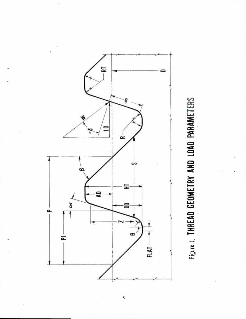
1. Thread geometry and load parameters. 5
2. Heywood's equation. 3
3. Thread characteristic from Heywood analysis for: 9 1. British Standard Buttress 2. Watervliet Buttress 3. Controlled root "V"
4. NASTRAN grid. 11
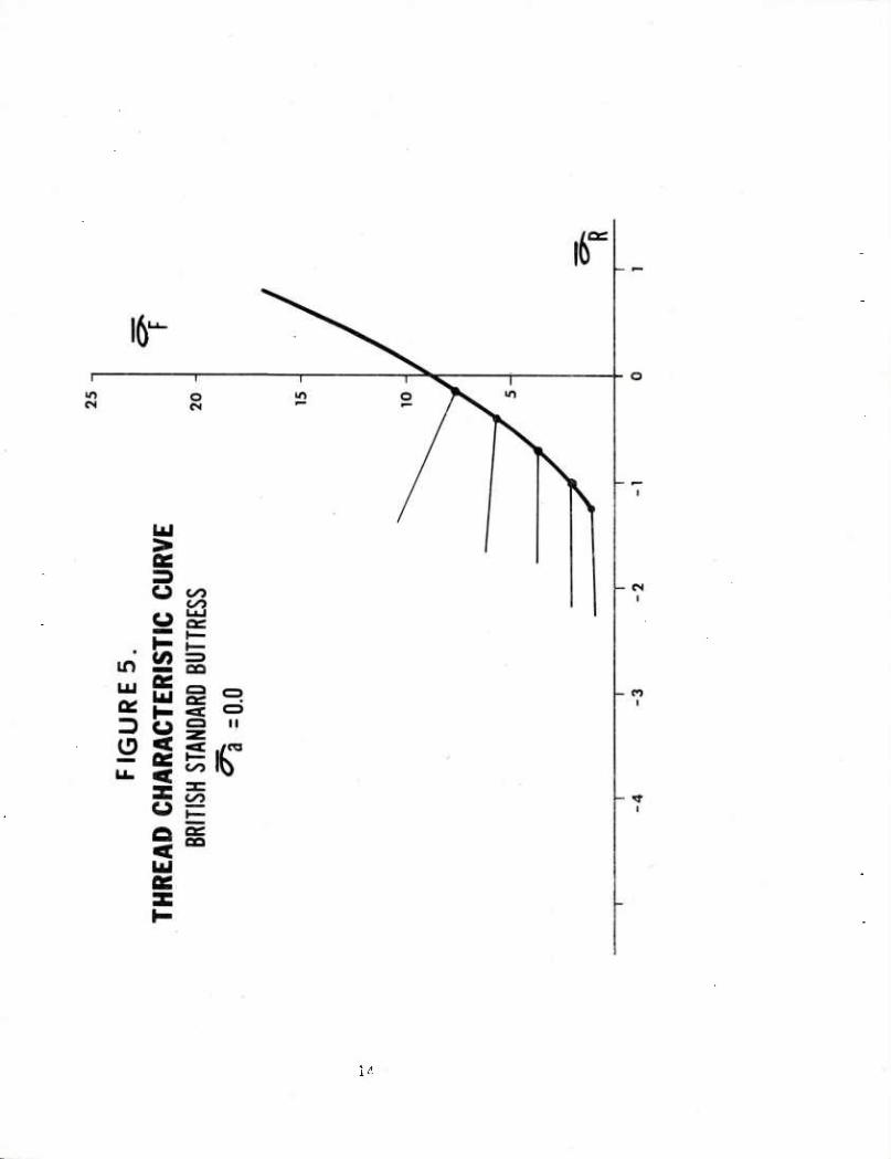
5. Thread characteristic curve - British Standard Buttress. 14
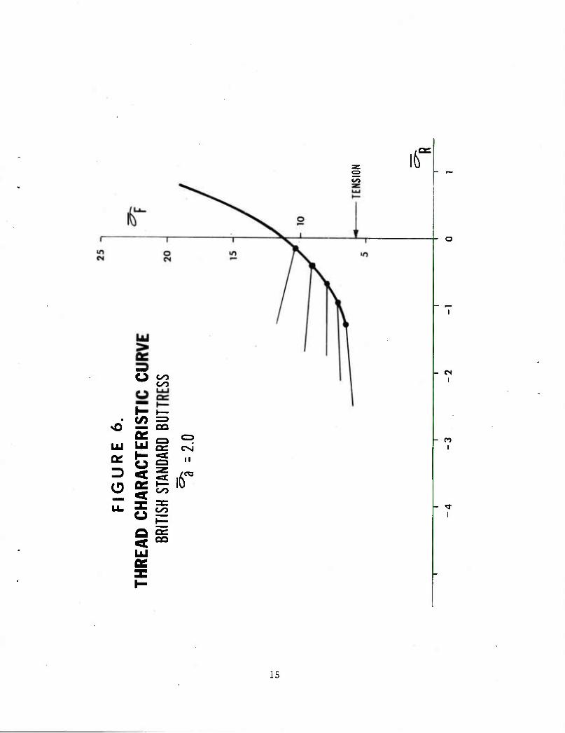
6. Thread characteristic curve - British Standard Buttress. 15
Al. Axial stress concentration thread characteristic curves. 20
A2. Watervliet Buttress for axial stress of 0.0. 21

Page
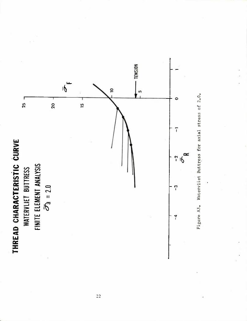
A3. Watervliet Buttress for axial stress of 2.0. 22
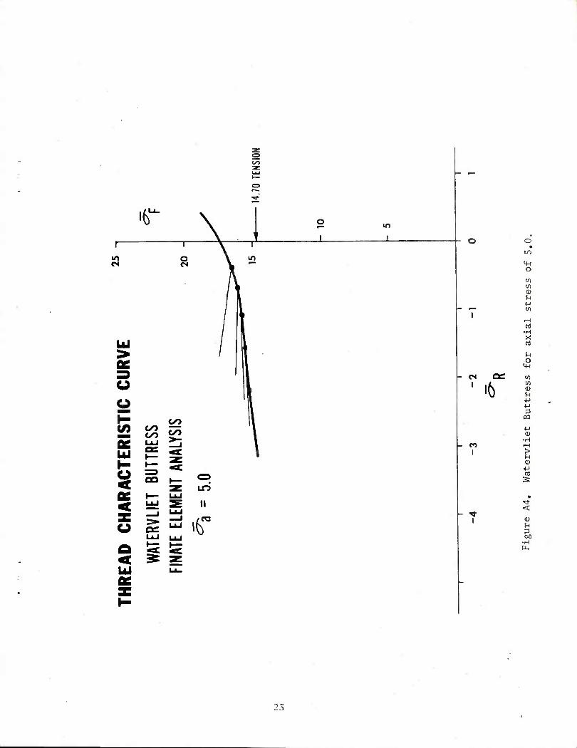
A4. Watervliet Buttress for axial stress of 5.0. 23
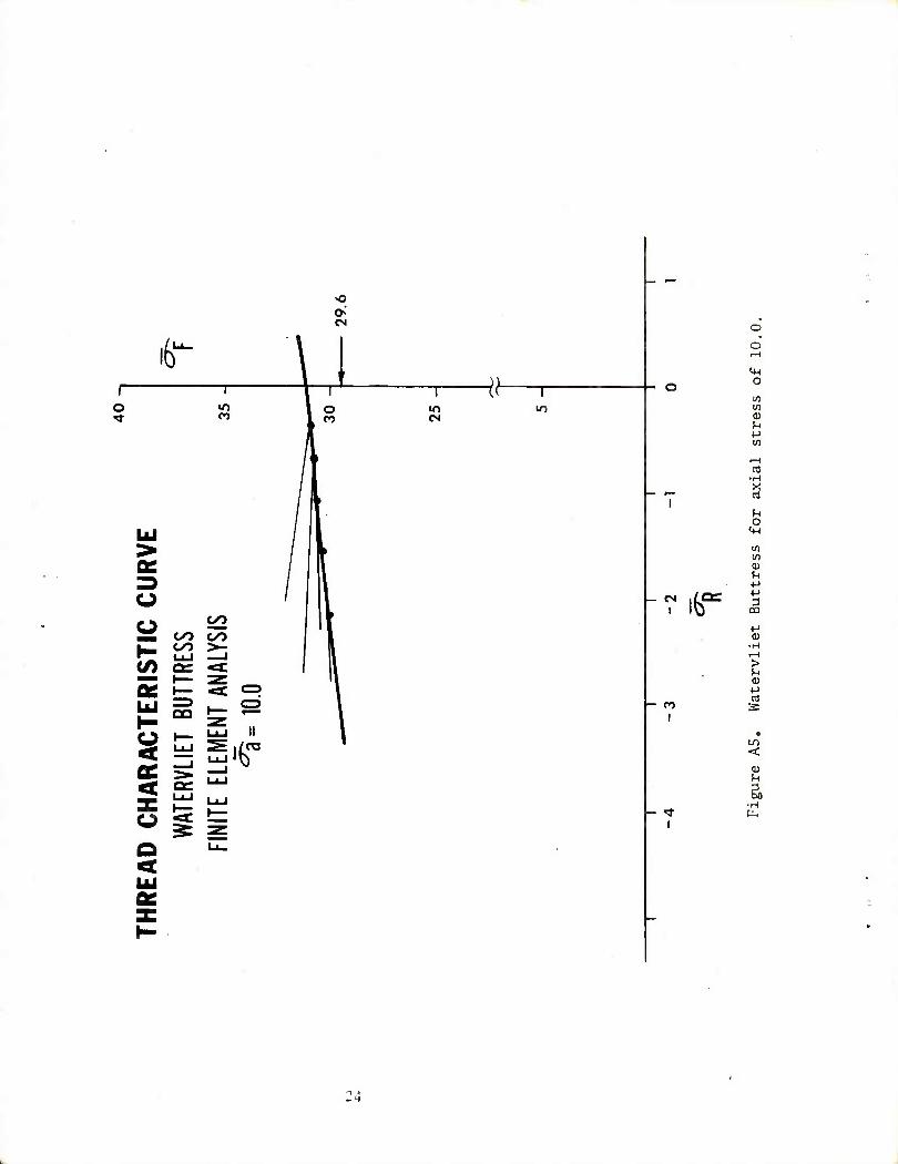
A5. Watervliet Buttress for axial stress of 10.0. 24
A6. British Standard Buttress for axial stress of 0.0. 25
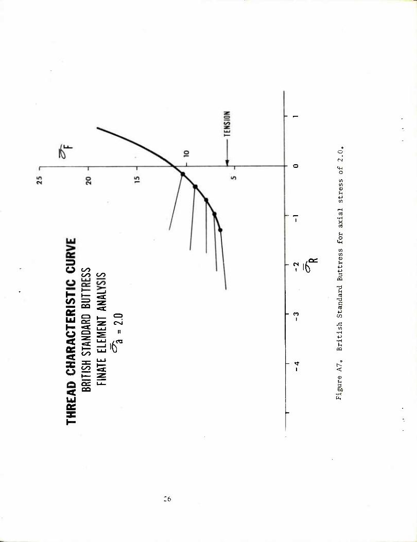
A7. British Standard Buttress for axial stress of 2.0. 26
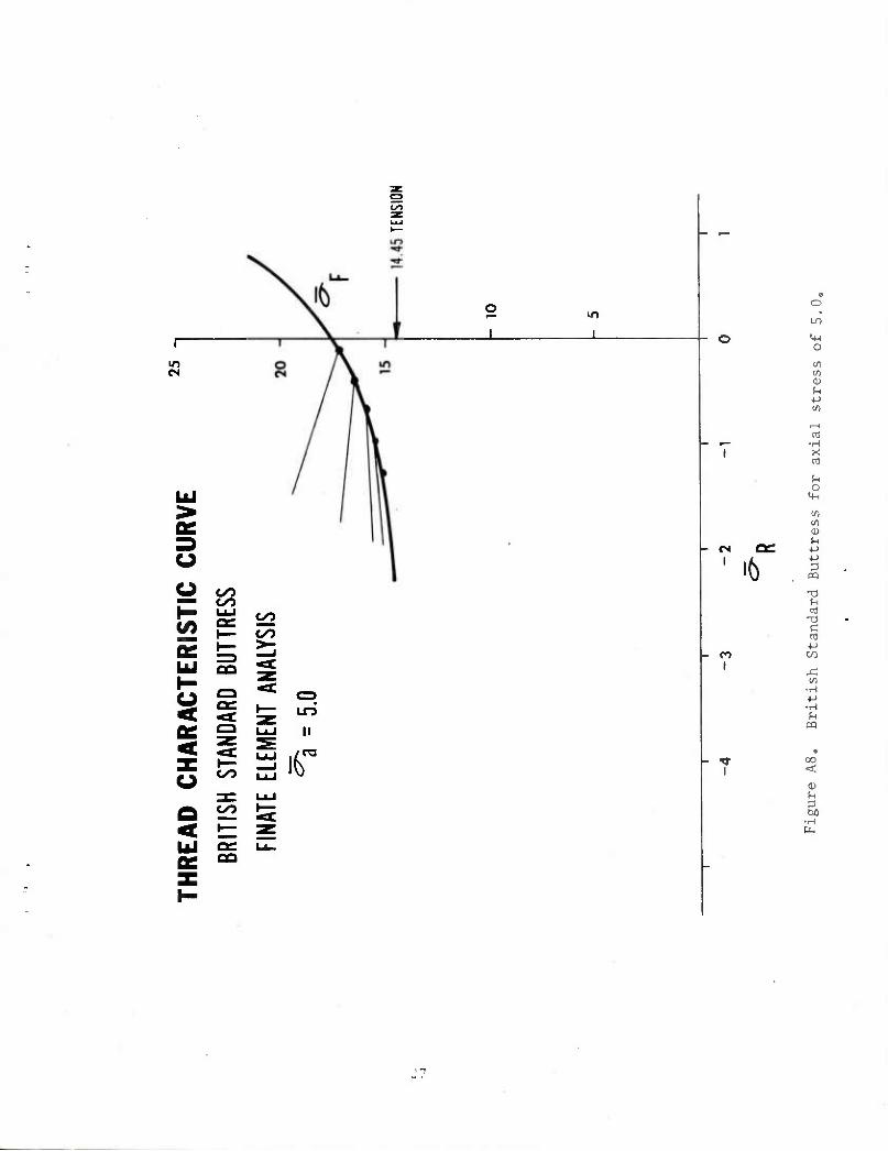
A8. British Standard Buttress for axial stress of 5.0. 27
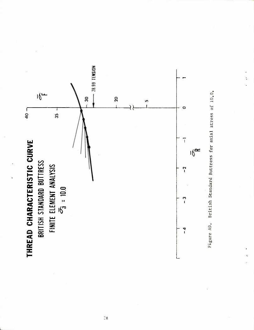
A9. British Standard Buttress for axial stress of 10.0. 28
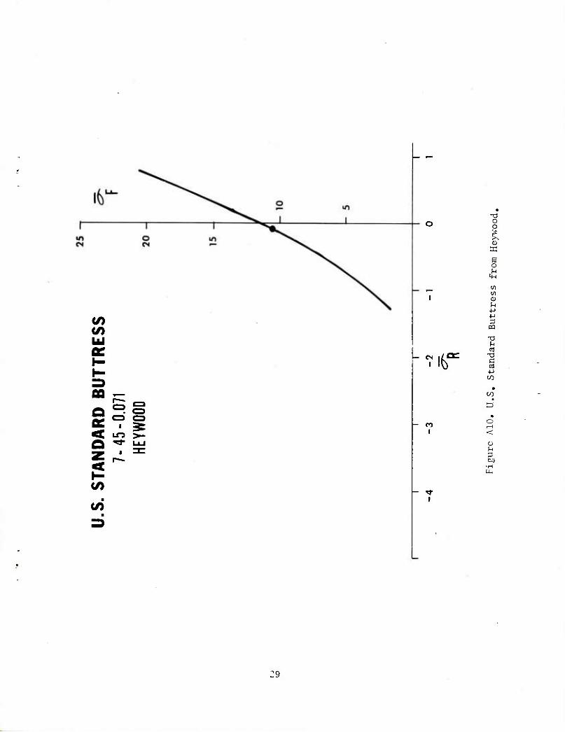
A10. U.S. Standard Buttress from Heywood. 29
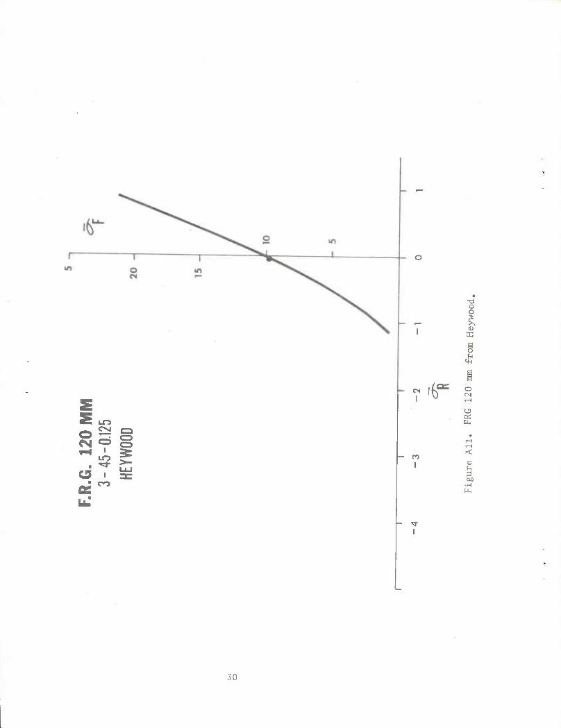
All. FRG 120 mm from Heywood. 30
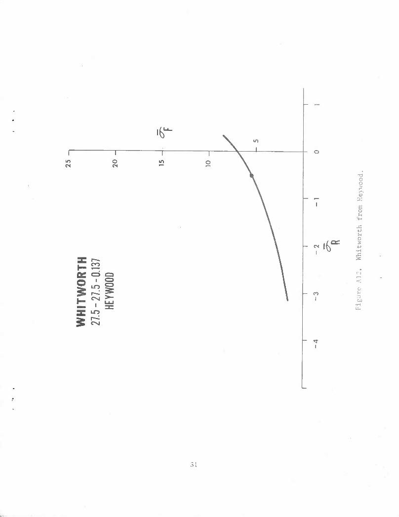
A12. Whitworth from Heywood. 31
A13. ISO Standard "V" cut and rolled from Heywood. 32
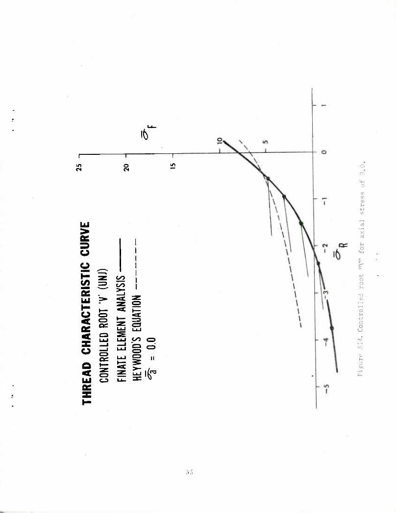
A14. Controlled root "V" for axial stress of 0.0, 33
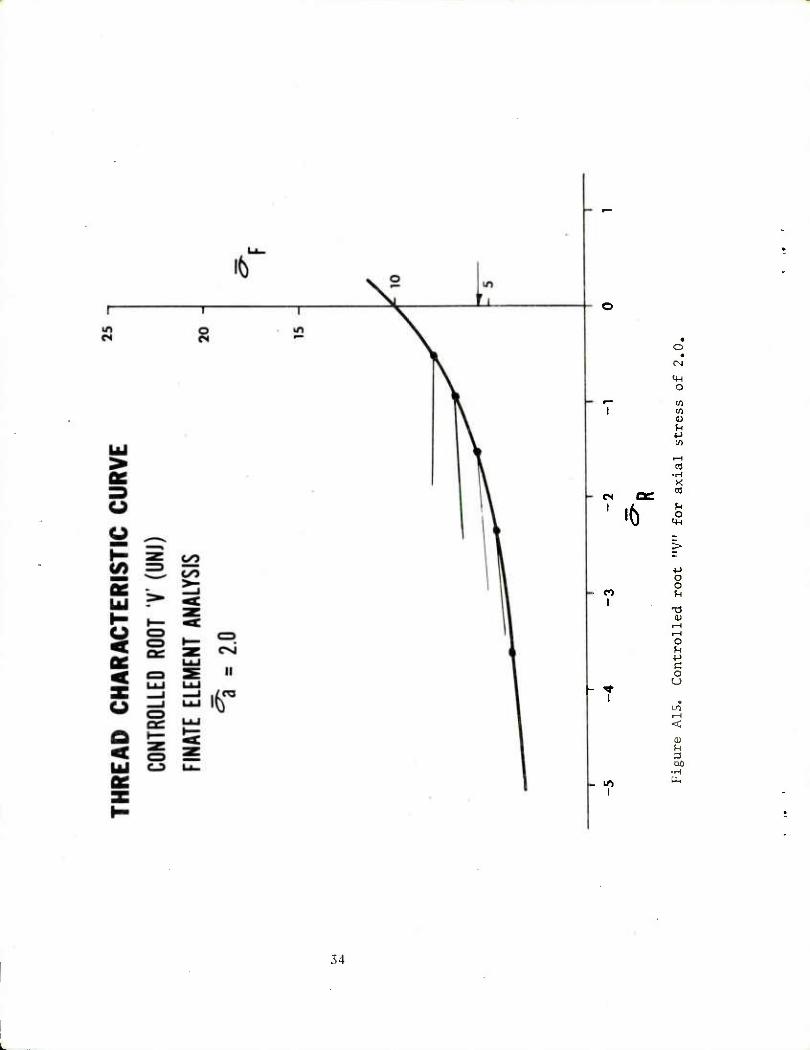
A15. Controlled root "V" for axial stress of 2.0. 34
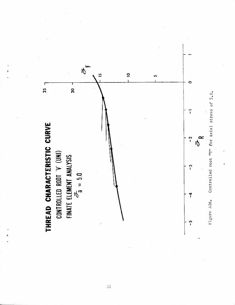
A16. Controlled root "V" for axial stress of 5.0. 35
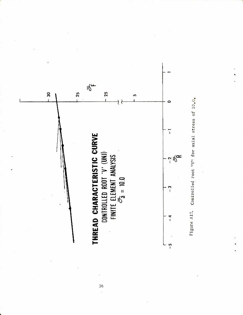
A17. Controlled root "V" for axial stress of 10.0. 36
A18. 175 mm - 8 Inch block from Heywood. 37
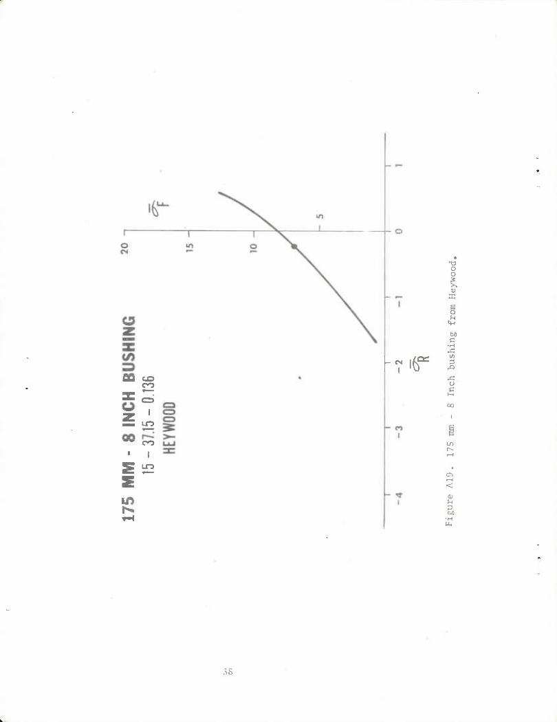
A19. 175 mm - 8 Inch bushing from Heywood. 38
A20. 175 mm - 8 Inch tube from Heywood. 39
11

INTRODUCTION
The concept that stress or flow lines concentrate around various
structural discontinuities is very old and has been the subject of
many books and technical papers. It is convenient to express this
concept in terms of a stress concentration factor (K) using the simple
equation:
a = K a max non
Where K is a ratio between the maximum stress and some nominal stress,
1 the single book. Stress Concentration Factors, by R. E. Peterson is
a compilation of the work included in some 378 references. The bulk
of this work is contained on graphs which are plots of K vs. some
geometry factor and most use a family of curves to show the effect of
some other geometry factor. These plots provide both useful numeric
information and a quick visual picture of the structural response.
The concept of stress concentration in screw threads is rather
elusive and in fact there is little work done on stresses in threads.
2 R. Bo Heywood published an empirical equation for the maximum fillet
3 stress which was used in the work of Weigle, Lasselle and Purtell
as a guide in trying to improve fatigue life of cannon breech rings.
Peterson, R. E., Stress Concentration Factors, John Wiley S Sons, New York, 1974.
2 Heywood, Ro B., "Tensile Fillet Stresses in Loaded Projections," Proceedings of the Institute of Mechanical Engineers, Vol. 160, p. 124, 1960.,
Weigle, Lasselle, and Purtell, "Experimental Behavior of Thread-Type Projections," Experimental Mechanics, May 1963.

Later this author demonstrated that the Heywood equation would give
accurate numeric data when the boundary conditions were closely con-
4 trolled.
However, most work with screw threads seems to be done for specific
cases such as the fine work of M. Hetinyi who investigated bolt shank
and nut design in Witworth threaded bolts. This type of analysis using
three dimensional photoelasticity was also used by W. F. Franz and 7
J. D. Chalupnik. A further attempt at optimizing a thread form was o
done by R, L0 Marino and W. F. Riley.
In all of these works the calculated stress concentration factor
is different for each thread in the system. It would seem that if the
stress concentration factor is properly defined something should be a
constant for all threads of a specific shape. In his original paper,
Heywood demonstrated part of the problem. The stress in the fillet
is the result of two factorso First, is the stress due to the load on
the individual thread tooth and second, is the stress due to the general
^•Hara, G„ P., "Finite Element Analysis of Threaded Connections," Proceedings of the Fourth Army Symposium on Solid Mechanics, September 1974.
Hetinyi, M., "The Distribution of Stress in Threaded Connections," Proceedings of SESA, Vol. 1, No. 1, 1943.
"Franz, W. F„, "Three-Dimensional Photoelastic Stress Analysis of a Threaded Pipe Joint," Proceedings of SESA, Vol. 9, No. 2, pp. 185- 194, 1952.
7 Chalupnik, J. D., "Stress Concentration in Bolt Thread Roots," Exper- imental Mechanics, 1967.
g Marino, R, L., and Riley, W. F., "Optimizing Thread-Root Contours Using Photoelastic Methods," Experimental Mechanics, January 1964, p. 1.
stress field or the axial stress (aa) near the thread fillet. In this
paper 1 will add effect due to friction and normalize all stresses to
the average shear transfer rate (TR).
When the friction force and the force due to the "wedge" effect of
the loaded flank of the thread are combined, a radial (normal) force
is produced which can be averaged into the radial stress (a ). The
fillet stress (Op) can be expressed as the sum of two functions.
aF/Tr = ^F = Gi(a'3,R,e,ar) + G2(a,a,R,e,aa)
In the above equation the first function (G1) is the relation
between fillet stress and the load on the individual thread tooth.
The second function (G2) is the factor due to the general stress field.
Alpha (a), beta (3), and R are the thread geometry factors. The angle
(0) is in both functions because they do not maximize at the same
position in the fillet. In this paper the shear transfer rate is
defined as the net load supported by the thread divided by the area
at the pitch line. The direction of the net load is parallel to the
pitch line and in the analysis this component of the force will be
unity. The radial stress (ar) and axial stress (a.) are normalized to
the shear transfer rate.
The above discussion relates to a normal screw thread problem
where only one flank of a particular thread contacts one flank of a
mating thread. In some structures the relative displacement in the
radial direction across the threaded connection is such that the radial
gap in the threads is closed and both flanks of each thread carry load.
Under these conditions the radial component of the loads add together
to produce high negative or compressive radial stress across the joint.
The axial loads oppose each other and the pressure on the primary flank
must become very high to overcome the secondary flank load. This is
not a common condition; however, it may become very important in the
cannon breech-to-tube connection.
THREAD GEOMETRY
The thread geometry parameters are shown in Figure 1 and in this
report all linear dimensions will be normalized to pitch (P). The
primary geometry parameters are the primary flank angle (a), the sec-
ondary flank angle (3) and the root radius R. These, in conjunction
with the pitch space (PI), define the basic thread geometry. Other
factors are required to insure a practical thread which will fit
together. The addendum (AD) and dedundum (DD) dimensions sum to the
total height (HT). The tip radius (RT) eliminates a sharp corner and
helps to support the bearing surface. The root flat (FLAT) is often
used to make up for the root radius tolerance. The bearing height (Z)
is used to calculate the average bearing stress and the shear length
(S) is used to calculate the maximum shear-out failure load.
This complicated system is simplified by the fact that we must
deal with a small set of standard thread forms. In this report detailed
analysis has been done on the British Standard Buttress thread and
Heywood analysis has also been done on the controlled root bolt thread
or "J" thread and the Watervliet Arsenal Buttress used on cannon
breeches. The nominal dimensions for these threads are shown in
Table I.
GO
tsx.

TABLE I. THREAD GEOMETRY DEFINITION
British Buttress
Watervliet Buttress
30 "V" (Rolled)
a 7° 20° 30°
3 45° 45° 30°
R 0.1205 0.1333 0.1804
PI 0.500 0.5276 0.500
HT 0.5059 0,4787 0.6077
RT 0.00 0.0480 0.1083
FLAT 0.0 0.0 0„0
LOADING PARAMETERS
The Heywood load parameters are also shown in Figure 1. They are
a point force (W) applied at some position (b) in the loaded flank with
a friction angle (y)• This scheme can be repeated many times on the
loaded flank to produce some load distribution curve. The following
loading assumptions are made:
1. The total load vector parallel to the datum line is unity.
2. The load distribution is uniform.
3. Friction does not vary along the flank.
The first assumption given allows the normalization of stresses
to shear transfer rate and the other two establish a simple loading
case.
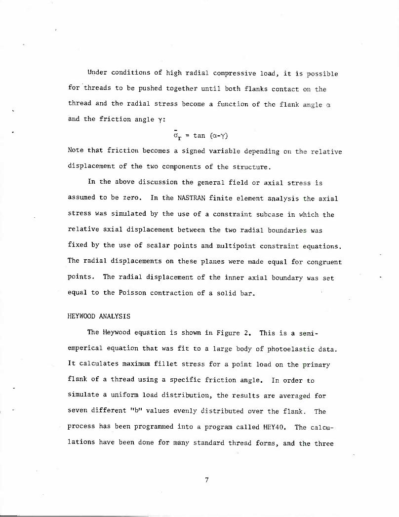
Under conditions of high radial compressive load, it is possible
for threads to be pushed together until both flanks contact on the
thread and the radial stress become a function of the flank angle a
and the friction angle y:
ar = tan (a-y)
Note that friction becomes a signed variable depending on the relative
displacement of the two components of the structure.
In the above discussion the general field or axial stress is
assumed to be zero. In the NASTRAN finite element analysis the axial
stress was simulated by the use of a constraint subcase in which the
relative axial displacement between the two radial boundaries was
fixed by the use of scalar points and multipoint constraint equations.
The radial displacements on these planes were made equal for congruent
points. The radial displacement of the inner axial boundary was set
equal to the Poisson contraction of a solid bar.
HEYWOOD ANALYSIS
The Heywood equation is shown in Figure 2. This is a semi-
emperical equation that was fit to a large body of photoelastic data.
It calculates maximum fillet stress for a point load on the primary
flank of a thread using a specific friction angle. In order to
simulate a uniform load distribution, the results are averaged for
seven different "b" values evenly distributed over the flank. The
process has been programmed into a program called HEY40. The calcu-
lations have been done for many standard thread forms, and the three
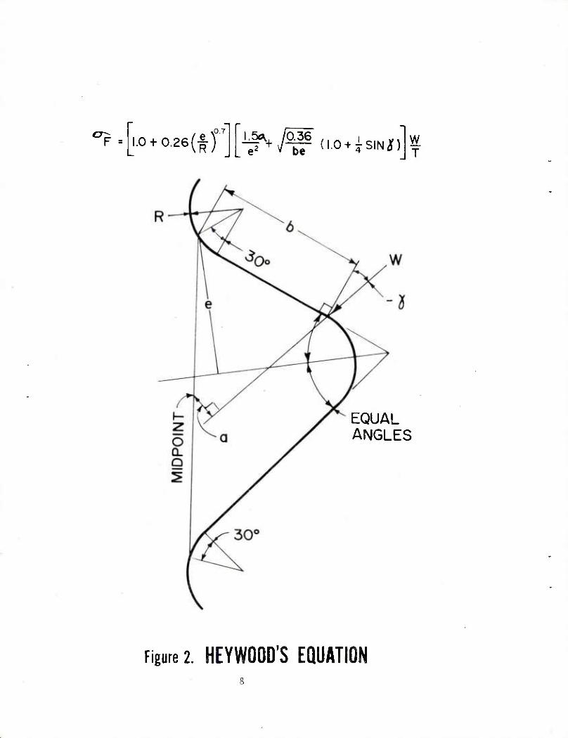
"F _I.O + 0.26(t)07][i^^(,.o + Xs,Ni)" w T
EQUAL ANGLES
Figure 2. HEYWOOD'S EQUATION
II II II 0© @
CO

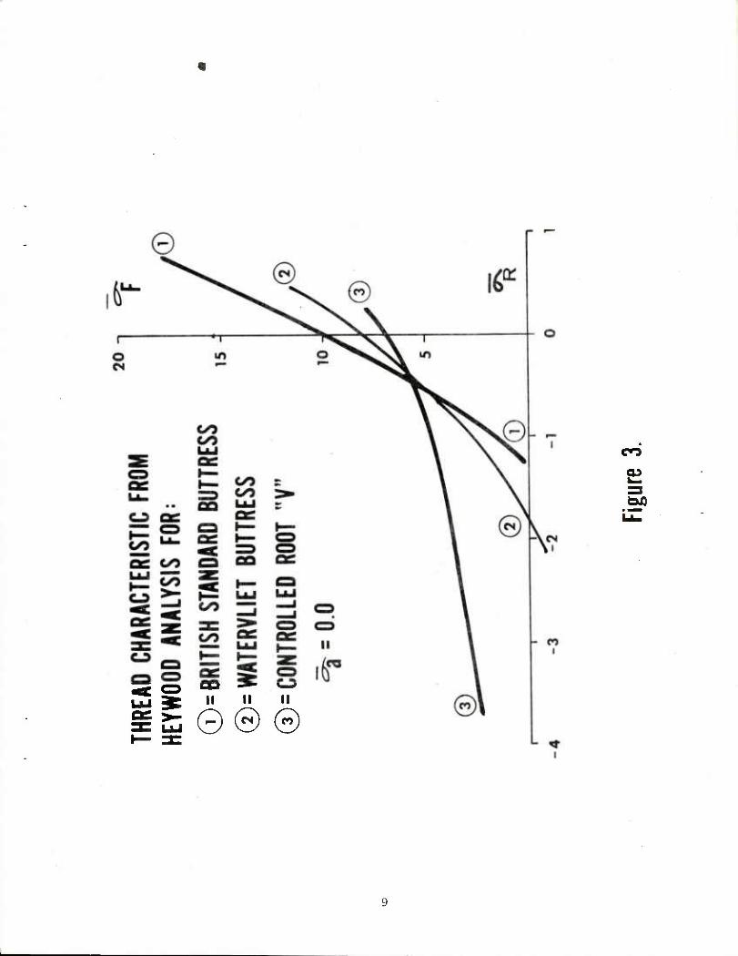
reported in Figure 3 have been defined in Table I. This plot of fillet
stresses plotted against radial stress will be referred to as the
"thread characteristic curve". This curve covers a friction angle
range of -45° to 45° or a coefficient of friction range of -1.0 to 1,0.
In Heywood's photoelastic experiments he was careful to transfer
the load supported by the threads profiled in a shear mode to make the
axial stress as small as possible. This process limited his equation
to the case where axial stress is equal to zero.
NASTRAN FINITE ELEMENT ANALYSIS
The finite element work was done for three reasons: (1) to
verify the Heywood analysis; (2) to examine the two-flank problem;
and (3) to include a finite axial stress. The grid for the British
Standard Buttress is shown in Figure 4. It contains 216 triangular
ring elements (CTRIARG) and 133 grid points. The run required five
basic loading subcases plus fourteen subcase combinations for each
value of axial stress. These fourteen subcases cover both 1-flank
and 2-flank contact over a range coefficient of friction of -1.0 to
loO in increments of 0.25.
9 The grid was generated using IGFES and following that, force
sets were calculated to apply uniform pressure and uniform shear loads
on both flanks of the thread and a displacement was calculated for a
nominal 1.0 psi axial load on the grid. Two different constraint
9 Lorensen, W. E., "Interactive Graphic Support for NASTRAN," Sixth NASTRAN User's Colloquium, NASA Conference Publication 2018, October 1977.
10

-1^- 4.412 ^
Figure 4. NASTRAN GRID
i:

conditions were required to complete the boundary conditions for a
single thread taken from a long series of threads. For loads on the
thread the inner boundary points were fixed in both radial and axial
directions and similar points on the two radial boundaries were con-
strained to equal displacements. In this way the net load was taken
out as shear load on the inner axial boundary and the multipoint con-
straint equations replaced adjoining material. For the axial load
condition the inner axial boundary was constrained to the Poisson
displacement in the radial direction and left free in the axial dir-
ection. The two radial boundaries were given fixed relative axial
displacements and the radial displacement was made equal for similar
grid points. This condition was set to simulate a far removed axial
loading.
Because the basic loads were all for a 1.0 psi uniform applied
pressure or shear and the results were desired for a 1.0 psi shear
transfer rate (calculated at the datum line), it became necessary to
calculate the correct Subcase Sequence Coefficients for fourteen sub-
cases for each of four axial stress values (or 56 sets). Therefore a
small program was generated to supply all necessary SUBCOM, SUBSEQ and
LABEL cards for that portion of the case control deck.
Uniform increments of 0.25 in coefficient were used from -1.0 to
1.0. If the friction was zero or less, a similar subcase combination
was generated along with one where both flanks were loaded and the
second radial stress was 1.0 greater than the initial.
12
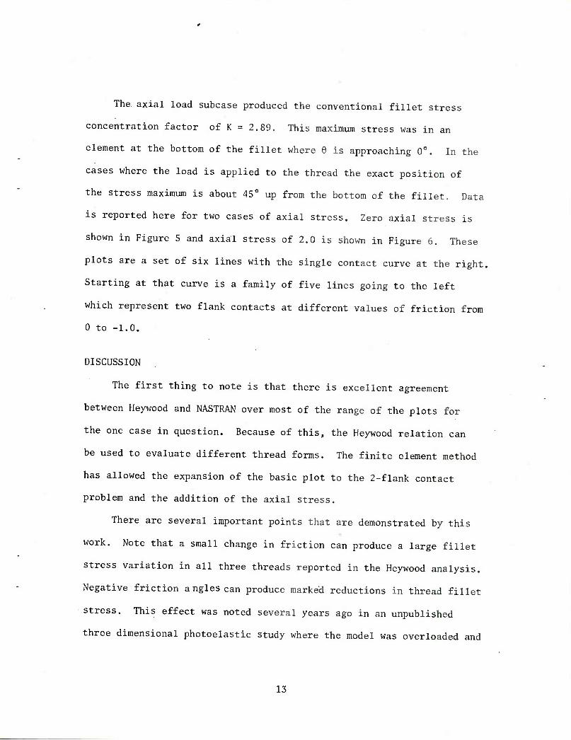
The axial load subcase produced the conventional fillet stress
concentration factor of K = 2.89. This maximum stress was in an
element at the bottom of the fillet where 6 is approaching 0°. In the
cases where the load is applied to the thread the exact position of
the stress maximum is about 45° up from the bottom of the fillet. Data
is reported here for two cases of axial stress. Zero axial stress is
shown in Figure 5 and axial stress of 2.0 is shown in Figure 6. These
plots are a set of six lines with the single contact curve at the right,
Starting at that curve is a family of five lines going to the left
which represent two flank contacts at different values of friction from
0 to -1.0.
DISCUSSION
The first thing to note is that there is excellent agreement
between Heywood and NASTRAN over most of the range of the plots for
the one case in question. Because of this, the Heywood relation can
be used to evaluate different thread forms. The finite element method
has allowed the expansion of the basic plot to the 2-flank contact
problem and the addition of the axial stress.
There are several important points that are demonstrated by this
work. Note that a small change in friction can produce a large fillet
stress variation in all three threads reported in the Heywood analysis.
Negative friction angles can produce marked reductions in thread fillet
stress. This effect was noted several years ago in an unpublished
three dimensional photoelastic study where the model was overloaded and
13
Kf
OS _ UJ Ul or a: tT ^
I
CD oo
CVJ
r I
S^ QQ
15
the threads were forced to a high negative radial stress. In this case
the fillet stresses were very low and the experiment was repeated.
This author suspects that friction variation may be responsible for
much of the scatter in bolt-fatigue data.
This work was initiated because of the necessity of analyzing a
structure with a long threaded connection using many small threads. In
this case the modeling of each thread would require an excessively
large data deck. Therefore, the threads were handled as a conventional
contact problem where friction could take on any value and limits were
applied to the radial stress. In the solution the contact surface was
placed on the datum line of the threads and one or two teeth were
replaced by one element space. Shear transfer rates could then be
estimated from the shear stress data near the contact surface along with
radial and axial stress. The fillet stresses were estimated for use in
fracture mechanics analysis,
CONCLUSION
A stress concentration approach to the thread fillet stress prob-
lem has been defined using the shear transfer rate as the fundamental
quantity. This stress concentration is plotted for a fixed geometry in
a stress vs. stress plot where the stress concentration is a function
of the applied radial stress. This process can be repeated for several
values of the applied axial load. The effects of axial stress and
applied thread loads seem to be of equal importance and accurate results
require the analysis of both factors.
16
REFERENCES
1. Peterson, R. E., Stress Concentration Factors, John Wiley £ Sons,
New York, 1974.
2. Heywood, R. B., "Tensile Fillet Stresses in Loaded Projections,"
Proceedings of the Institute of Mechanical Engineers, Vol. 160,
p. 124, 1960.
3. Weigle, Lasselle and Purtell, "Experimental Behavior of Thread-
Type Projections," Experimental Mechanics, May 1963.
4. O'Hara, G. P., "Finite Element Analysis of Threaded Connections,"
Proceedings of the Fourth Army Symposium on Solid Mechanics,
September 1974.
5. Hetinyi, M., "The Distribution of Stress in Threaded Connections,"
Proceedings of SESA, Vol. 1, No. 1, 1943.
6. Franz, W. F., "Three-Dimensional Photoelastic Stress Analysis of a
Threaded Pipe Joint," Proceedings of SESA, Vol. 9, No. 2, pp. 185-
194, 1952.
7. Chalupnik, J. D., "Stress Concentration in Bolt Thread Roots,"
Experimental Mechanics, 1967.
8. Marino, R. L., and Riley, W. F., "Optimizing Thread-Root Contours
Using Photoelastic Methods," Experimental Mechanics, January 1964,
p. 1.
9. Lorensen, W. E., "Interactive Graphic Support for NASTRAN," Sixth
NASTRAN User's Colloquim, NASA Conference Publication 2018,
October 1977.
17

APPENDIX A
This appendix was written to provide an expanded data base for the
application of the thread characteristic plot concept. The curves quoted
are from one of two sources, finite element analyses using the NASTRAN code
or the solution of Heywood's equation using a small program called HEY40.
The basic curves calculated from Heywood use an average of seven distributed
loads at each data point„ The NASTRAN run use a constant pressure or shear
type of loading. These plots also add the two face contact condition and
provide a separate plot for axial stresses of 0„0, 2o0, 5.0, and 10.0 times
the shear transfer rate,,
Table I shows the geometry parameters for all the thread forms in ques-
tion. The definition of these can be taken from Figure 1 of the main body
of the report.
Figure Al in the Appendix is a plot of the conventional tensile stress
concentration factor vs. nondimensional root radius (R) <, This is the result
of NASTRAN analysis of the threads in the Appendix and other thread like
projections. It appears that this tensile stress concentration provides the
minimum stress value to which stress due to Heywood type loads are added to
provide the maximum stress in the fillet.
18

TABLE Alo THREAD GEOMETRY PARAMETERS
Thread c*. P RT
Watervliet Buttress 20 45 .133 .048 .395 .731
British Standard Buttress
7 45 .121 o0 .400 .724
U.S. Standard Buttress
7 45 .071 .0 .600 .837
FRG 120 mm" r 3 45 .105 .040 .362 .679
Whitworth 27.5 27. 5 ol37 .137 .493 .756
ISO Standard 'V (cut)
30 30 .144 .0 .542 .751
ISO Standard "V (rolled)
30 30 .144 .108 .488 .751
Controlled Symbol UNJ
Root 30 30 .180 .108 .478 .740
175 mm - 8 Block
Inch 35 35 .120 .182 .355 .803
175 mm - 8 Bushing
Inch 15 37. 15 .136 .0 .451 .725
175 mm - 8 Tube
Inch** 14.5 14.5
14. 14.
5 5
.027
.013 .040 .040
.240
.250 .580 .585
*This form has a root flat of .072. **A specific case of a Stub Acme Modified Form 2.
19

d
CN
LO
"T"
10 0) >
u
+J u ed u cd X u
CO
X
o -H 4J ed Ki +J C OJ CJ n o o
w; in 0) U ♦J '/,
(/)
O J fig o o (^
(^
o o
oo
Of
oo
^ LU oo C3 Q= CS QC 3C =>
X
0 z <
y u
LO
CO
O 3
< U UJ a. co
»
n
o <
x
ed •H
<
a;
a M
20

It)
o CM
m
u
O o
ffi ^ g
LU
i■ i CD M
II
TO l
o CO
in
X CD
fn O
tn to Q) FH
■M
■M OJ
•H r—I
>
*J 03
<
M •r-i
21
oo
«
o
Ul
O to rr CO
(^
- CN
''(>
evi ll
I
* S€
o I
o
m ID U
X
U o
W
1) M
BQ
•1> •H
> 0)
3=
to < 0)
a •H a.
22
«L U-i
_J_
o
o
oo v> <* z* GO
- CO
in
II
CT3
lG
I id
i
14-1 O
tn m
h +-i in
cd
o
U) W 0) U
^3 C3
> U
< O 'H
•H
23
r ih
o CM
1/1
o
to in o
OS
o o ¥> 21 oo oo L. oo >- </> or <a: flg t ^ LU —3 .
O •— ^ 2 = a* o « =
- CM
Itf
CO I
II
03 •H X rt
in o u
■p ■p
03
O
LO
i
24

5 o o U_i
[Z ■
OO (^
OQ oo OS Ixl
< OO
±3
U-l
LLJ D'S E
QUAT
ION
^a
= 0.0
o t— u ul CD
OO
- CN i
i
- t l
o in
If)
■H
cd
m to 01 u *J
ca
u cd
+-> CO
4= to
•H
•H U
ca
E •H
13
- (N 16
(^ OQ
n
C^5 id
OJ II
03
o
o
IS) CD
cd •H X nj
(H O
tn in <u u
■p ■t-> 3
CQ
-d h
c cd
in •H ■P •H
oa
Q| QC l-i_
1 < <D
a M
•H
:6
— GO
S « ^ !LI »^ C/5
UJ m
o
_l_ _l_
LO
x ^ a ifT g OO LJJ 'V)
oo
CM
I «
I
I
o w 1/1 o h 10
cd
o <4-l
m w o fn 4J +J "i
-a rt
-o c rt
+J ui
Xi in
•H ■p •H
OQ
CO <
U
■H
CXI
^
ir o
o ^3 ^2 -S. or oo
(/)
UJ
o
o in
-!)-
l6C
I
CQ
OO SiS 11
03
CO
I
o — — i— 5 Q S u- i
o
p
03 ■H X 03
u o
tw yi
CD U •M -M
ca
03
u CO
in •H ♦J •H
bo tL.
CO CO
a: ■ in
- CM
Itf
00 I
• -a o o
0
e o
w 7) <u u *J +J 3
ca
-a
a3 ■a c
4-) to
o I—(
< a>
C'J •H
29
7 '(f
* -d o o
§
o
LO CSJ
OJ LO
C5 I
CO •H
l
ir
CN O CM
U")
CN
I ^
■a o o
::. (U
B o
O
+-» •H X is
cr>
o 5 I—^
I I z:
•H
CM
I
31

- CN tf
- CO
CO I
o CO
i- rr
o o
E o
-a
o
+-> 3 u
-a u si
13 C a
o en
M
(30 •H
32
Id
ID CM
O in
u a: o o ^ IT z oo ^ = Co
UJ UJ t/2
i ■ » CZi ||
1 ^^
o
"-. 0)
4-' 1/1
o o ^^
O
c o u
.■>.}
CM
I «
CO
I
- n
i
O
if) (D M
+-> in
X
O
u o o
O
C o u
m
4)
s ■H
34
It) o
_l_ _l_
o CM
<o = 55 CO
l±! ^i(i'
II
03
CM
I Id
I
I
u-i l
o
0)
n •H K cd
!H O
>
o o
-a o
o
C o u
■H
JO
1(>L
o CO CN cs m
i^ o
o o -^(f
<4H O
in
o ■M
id ■H
o
(^
UJ
o CD
U-l II
< CD UU
tt UU
U-i i(r < ^ uu iXI rv \— o 1— z
o CD u_
— CO
I
4J o o u
13 0}
o
p o u
o H
li,
>— m
36

r o CM O
_L_
o o
CNJ
00 ^
_ CO
in
T3 O o
M o o
u
oo
I
00
< 0)
■H
-7i(f CD CO
i
CO
• I
XI o o
6 O
bo C
•H
tfl 3
XI
o c
oo
I
IT)
<
CO •H
38
k

I
-a o o 2
a: E o
u C
oo
o <
U 3 CO
l()C
I
1
39
TECHNICAL REPORT INTERNAL DISTRIBUTION LIST
CCMMANDER
CHIEF, DEVELOPMENT ENGINEERING BRANCH , ATTN: DRDAR-LCB-DA
-DM -DP -DR -DS -DC
CHIEF, ENGINEERING SUPPORT BRANCH ATTN: DRDAR-LCB-SE
-SA
CHIEF, RESEARCH BRANCH ATTN: DRDAR-LCB-RA
-RC -RM -RE
CHIEF, LWC MORTAR SYS. OFC. ATTN: DRDAR-LCB-M
CHIEF, IMP. SIMM MORTAR OFC. ATTN: DRDAR-LCB-^I
TECHNICAL LIBRARY ATTN: DRDAR-LCB-TL
TECHNICAL PUBLICATIONS & EDITING UNIT ATTN: DRDAR-LCB-TL
DIRECTOR, OPERATIONS DIRECTORATE
DIRECTOR, PROCUREMENT DIRECTORATE
DIRECTOR, PRODUCE ASSURANCE DIRECTORATE
NO. OF COPIES
1 1 1 1 1 1 1
1 1 1
2 1 1 1 1
1 1
1 1
1
1
1
NOTE: PLEASE NOTIFY ASSOC. DIRECTOR, BENET WEAPONS LABORATORY, ATTN; DRDAR-LCB-TL, OF ANY REQUIRED CHANGES.
TECHNICAL REPORT EXTERNAL DISTRIBUTION LIST
NO. OF COPIES
>
ASST SEC OF THE ARMY RESEARCH & DEVELOPMENT ATTN: DEP FOR SCI & TECH THE PENTAGON WASHINGTON, D.C. 20315
CCMMNDER US ARMY MAT DEV & READ. ATTN: DRCDE 5001 EISENHOWER AVE
ALEXANDRIA, VA 22333
CCMMANDER
US ARMY ARRADCCM ATTN: DRDAR-LC
-ICA
CCMD
PLASTICS TECH EVAL CEN)
1 1
1 1 1 1 2
-LCE -LCM -LCS
-LCW -TSS(STINFO)
DOTOR, NJ 07301
CCMMANDER US ARMY ARRCCM ATTN: DRSAR-LEP-L ROCK ISLAND ARSENAL ROCK ISLAND, IL 61299
DIRECTOR US Amy Ballistic Research Laboratory ATTN: DRDAR-TSB-S (STINFO) 1 ABERDEEN PROVING GROUND, MD 21005
CCMMANDER US ARMY ELECTRONICS CCMD ATTN: TECH LIB 1 FT MONMOUTH, NJ 07703
CCMMANDER US ARMY MOBILITY EQUIP R&D CCMD ATTN: TECH LIB 1 FT BELVOIR. VA 22060
COMMANDER
US ARMY TANK-AUTMV R&D CCMD ATTN: TECH LIB - DRDTA-UL
MAT LAB - DRDTA-RK WARREN MICHIGAN A«90
CCMMANDER US MILITARY ACADEMY ATTN: CHMN, MECH FNGR DEPT WEST POINT, NY 10996
CCMMANDER REDSTONE ARSENAL ATTN: DRSMI-RB
-RRS -RSM
ALABAMA 35809
CCMMANDER ROCK ISLAND ARSENAL ATTN: SARRI-ENM (MAT SCI DIV) ROCK ISLAND, IL 61202
CCMMANDER HQ, US ARMY AVN SCH ATTN: OFC OF THE LIBRARIAN FT RUCKER, ALABAMA 36362
CCMMANDER US ARMY FGN SCIENCE & TECH CEN ATTN: DRXST-SD 220 7TH STREET, N.E. CHARLOTTESVILLE, VA 22901
CCMMANDER US ARMY MATERIAIS & MECHANICS
RESEARCH CENTER ATTN: TECH LIB - DRXMR-PL WATERTOWN, MASS 02172
NO. OF COPIES
1 1
2 1 1
NOTE: PLEASE NOTIFY CCMMANDER, ARRADCCM, ATTN: BENET WEAPONS LABORATORY, DRDAR-LCB-TL, WATERVLIET ARSENAL, WATERVLIET, N.Y. 12189, OF ANY REQUIRED CHANGES.
TECHNICAL REPORT EXTERNAL DISTRIBUTION LIST (CONT)
NO. OF
CCMMNDER US ARMY RESEARCH OFFICE- P.O. BOX 12211 RESEARCH TRIANGLE PARK, NC 27739
CCWMANDER US ARMY HARRY DIAMOND LAB ATTN: TECH LIB 2800 POWDER MILL ROAD ADELPHIA, MD 20783
DIRECTOR US ARMY INDUSTRIAL BASE ENG ACT ATTN: DRXPE-MT ROCK ISLAND, IL 61201
CHIEF, MATERIALS BRANCH US ARMY R&S GROUP, EUR BOX 65, FPO N.Y. 09510
CCMMANDER NAVAL SURFACE WEAPONS CEN ATTN: CHIEF, MAT SCIENCE DIV DAHIGREN, VA 22^48
DIRECTOR US NAVAL RESEARCH LAB ATTN: DIR, MECH DIV
CODE 26-27 (DOC LIB) WASHINGTON, D. C. 20375
NASA SCIENTIFIC & TECH INFO FAC P0 0. BOX 8757, ATTN: ACQ BR BALTIMORE/WASHINGTCN INTL AIRPORT MARYLAND 212<40
1 1
CCWMANDER DEFENSE TECHNICAL INFO CENTER ATTN: DTLA-TCA CAMERON STATION ALEXANDRIA, VA 223U
METALS & CERAMICS INFO CEN BATTELLE COLUMBUS LAB 505 KING AVE COLUMBUS, OHIO 43201
MECHANICAL PROPERTIES DATA CTR BATTELLE COLUMBUS LAB 505 KING AVE COLUMBUS, OHIO 43201
MATERIEL SYSTEMS ANALYSIS ACTV ATTN: DRXSY-MP ABERDEEN PROVING GROUND MARYUND 21005
NO. OF COPIES
12
NOTE: PLEASE NOTIFY COvMANDER, ARRADCCM, ATTN: BENET WEAPONS LABORATORY, DRDAR-LCB-TL, WATERVLIET ARSENAL, WATERVLIET, N.Y. 12189, OF ANY REQUIRED CHANGES.
i