t e s t r e p o r t no.: 16-1-0019501t07a - fcc id search€¦t e s t r e p o r t no.:...
TRANSCRIPT

Page 1 of 37 The test results relate only to the individual items which have been tested. This report shall not be reproduced in parts without the written approval of the testing laboratory © Copyright: All rights reserved by CETECOM
T E S T R E P O R T No.: 16-1-0019501T07a
GSM/W-CDMA Module SARA-U201
FCC-ID: XPY1CGM5NNN
IC: 8595A-1CGM5NNN PMN: SARA-U201 HVIN: SARA-U201
According to: FCC Regulations
Part 22, Part 24, Part 15C
IC-Regulations RSS-132 Issue 3, RSS-133 Issue 6,
RSS-Gen Issue 4
u-Blox AG
Laboratory Accreditation and Listings
MRA US-EU 0003
Industry Canada
Reg. No.: 3462D-1 Reg. No.: 3462D-2 Reg. No.: 3462D-3
Voluntary Controls for Electromagnetic Emissions
Reg. No.: R-2666 C-2914, T-1967, G-301
accredited according to DIN EN ISO/IEC 17025
CETECOM GmbH Laboratory Radio Communications & Electromagnetic Compatibility
Im Teelbruch 116 • 45219 Essen • Germany Registered in Essen, Germany, Reg. No.: HRB Essen 8984
Tel.: + 49 (0) 20 54 / 95 19-954 • Fax: + 49 (0) 20 54 / 95 19-964 E-mail: [email protected] • Internet: www.cetecom.com
for

Test Report 16-1-0019501T07a, Page 2 of 37
CETECOM_TR16_1_0019501T07a
Table of contents
1. SUMMARY OF TEST RESULTS...................................................................................................................... 3
1.1. TX mode, Test overview of FCC and Canada IC (RSS) Standards ................................................................. 3
1.2. RX mode, tests overview according FCC Part 15B and Canadian RSS Standards ......................................... 4
1.3. Attestation:....................................................................................................................................................... 4
2. ADMINISTRATIVE DATA ............................................................................................................................... 5
2.1. Identification of the testing laboratory ............................................................................................................. 5
2.2. Test location .................................................................................................................................................... 5
2.3. Organizational items ........................................................................................................................................ 5
2.4. Applicant’s details ........................................................................................................................................... 5
2.5. Manufacturer’s details ..................................................................................................................................... 5
3. EQUIPMENT UNDER TEST (EUT) ................................................................................................................. 6
3.1. TECHNICAL DATA OF MAIN EUT DECLARED BY APPLICANT ......................................................... 6
3.2. EUT: Type, S/N etc. and short descriptions used in this test report ................................................................ 7
3.3. Auxiliary Equipment (AE): Type, S/N etc. and short descriptions .................................................................. 7
3.4. EUT set-ups ..................................................................................................................................................... 7
3.5. EUT operating modes ...................................................................................................................................... 8
3.6. Parameter Settings on mobile phone and base station CMU200 ..................................................................... 9
3.7. Configuration of cables used for testing .......................................................................................................... 9
4. DESCRIPTION OF TEST SYSTEM SET-UP’S .............................................................................................. 10
4.1. Test system set-up for conducted measurements at antenna port .................................................................... 10
4.2. Test system set-up for radiated spurious emission measurements ................................................................... 12
5. MEASUREMENTS ............................................................................................................................................. 13
5.1. RF-Parameter - RF Peak power output conducted and PAPR-value ............................................................... 13
5.2. RF-Parameter - Occupied bandwidth and emission bandwidth ....................................................................... 15
5.3. RF-Parameter - Conducted out of Band RF emissions and Band Edge ........................................................... 16
5.4. RF-Parameter - Frequency stability on temperature and voltage variations .................................................... 20
5.5. RF-Parameter - Radiated out of Band RF emissions and Band Edge .............................................................. 27
5.6. General Limit - Radiated field strength emissions below 30 MHz .................................................................. 30
5.7. Measurement uncertainties .............................................................................................................................. 32
6. ABBREVIATIONS USED IN THIS REPORT ................................................................................................. 33
7. ACCREDITATION DETAILS OF CETECOM’S LABORATORIES AND TEST SITES ......................... 33
8. INSTRUMENTS AND ANCILLARY ................................................................................................................ 34
8.1. Used equiment “CTC” ..................................................................................................................................... 34
9. VERSIONS OF TEST REPORTS (CHANGE HISTORY) ............................................................................. 37
Table of annex Total pages
Annex 1: Measurement diagrams 53
Annex 2: External photographs of EUT 8
Annex 3: Internal photographs of EUT TO BE PROVIDED BY APPLICANT
Annex 4: Test set-up photographs 9
The listed attachments are an integral part of this report.
Test Report 16-1-0019501T07a, Page 3 of 37
CETECOM_TR16_1_0019501T07a
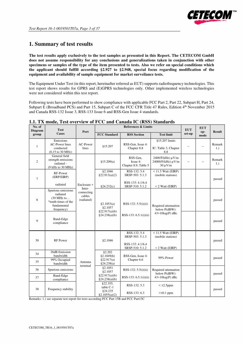
1. Summary of test results
The test results apply exclusively to the test samples as presented in this Report. The CETECOM GmbH
does not assume responsibility for any conclusions and generalizations taken in conjunction with other
specimens or samples of the type of the item presented to tests. Also we refer on special conditions which
the applicant should fulfill according §2.927 to §2.948, special focus regarding modification of the
equipment and availability of sample equipment for market surveilance tests.
The Equipment Under Test (in this report, hereinafter referred as EUT) supports radiofrequency technologies. This
test report shows results for GPRS and (E)GPRS technologies only. Other implemented wireless technologies
were not considered within this test report.
Following tests have been performed to show compliance with applicable FCC Part 2, Part 22, Subpart H, Part 24,
Subpart E (Broadband PCS) and Part 15, Subpart C of the FCC CFR Title 47 Rules, Edition 4th November 2015
and Canada RSS-132 Issue 3, RSS-133 Issue 6 and RSS-Gen Issue 4 standards.
1.1. TX mode, Test overview of FCC and Canada IC (RSS) StandardsNo. of
Diagram
group
Test
Cases Port
References & Limits
EUT
set-up
EUT
op-
mode
Result FCC Standard RSS Section Test limit
1
Emissions
AC-Power lines
conducted
(0,15 to 30 MHz)
AC-Power
lines §15.207
RSS-Gen, Issue 4:
Chapter 8.8
§15.207 limits
IC: Table 3, Chapter
8.8
-- -- Remark
1.)
2
General field
strength emissions
radiated -
(9 kHz to 30 MHz)
Enclosure +
Inter-
connecting
cables
(radiated)
§15.209(a)
RSS-Gen,
Issue 4:
Chapter 8.9, Table 5
2400/F(kHz) µV/m
24000/F(kHz) µV/m
30 µV/m
-- -- Remark
1.)
7
RF-Power
(ERP/EIRP)
radiated
§2.1046
§22.913(a)(2)
§24.232(c)
RSS-132: 5.4
SRSP-503: 5.1.3
RSS-133: 4.1/6.4
SRSP-510: 5.1.2
< 11.5 Watt (EIRP)
(mobile stations)
< 2 Watt (EIRP)
passed
8
Spurious emissions
radiated
(30 MHz to…
*tenth-times of the
fundamental
frequency)
§2.1053(a)
§2.1057
§22.917(a)(b)
§24.238(a)(b)
RSS-132: 5.5(i)(ii)
RSS-133: 6.5.1(i)(ii)
Required attenuation
below P(dBW):
43+10log(P) dBc
passed
9 Band-Edge
compliance passed
30 RF Power
Antenna
terminal
§2.1046
RSS-132: 5.4
SRSP-503: 5.1.3
RSS-133: 4.1/6.4
SRSP-510: 5.1.2
< 11.5 Watt (EIRP)
(mobile stations)
< 2 Watt (EIRP)
passed
34 26dB Emission
bandwidth §2.202
§2.1049(h)
§22.917(a)
§24.238(a)
RSS-Gen, Issue 4:
Chapter 6.6 99% Power passed
35 99% Occupied
bandwidth
36 Spurious emissions §2.1051
§2.1057
§22.917(a)(b)
§24.238(a)(b)
RSS-132: 5.5(i)(ii)
RSS-133: 6.5.1(i)(ii)
Required attenuation
below P(dBW):
43+10log(P) dBc
passed
37 Band-Edge
compliance
38 Frequency stability
§22.355,
table C-1
§24.235
§2.1055(a)(2)
RSS-132: 5.3
RSS-133: 6.3
< ±2.5ppm
<±0.1 ppm
passed
Remarks: 1.) see separate test report for tests according FCC Part 15B and FCC Part15C

Test Report 16-1-0019501T07a, Page 5 of 37
CETECOM_TR16_1_0019501T07a
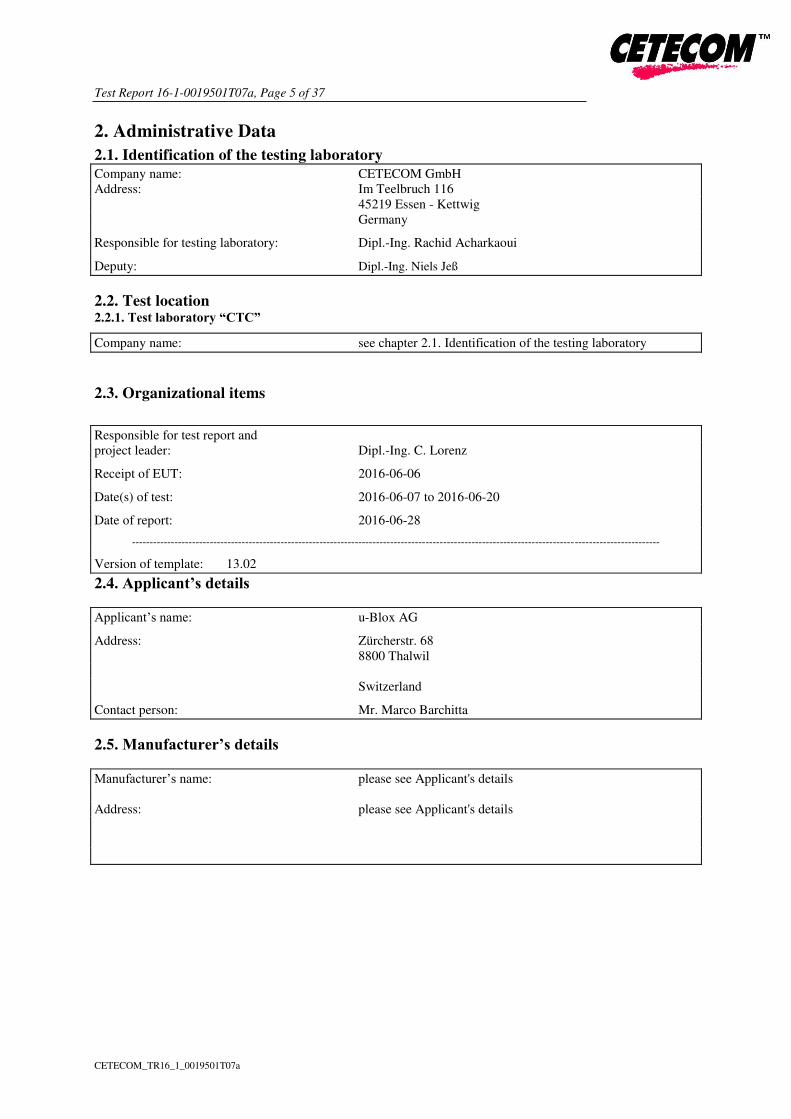
2. Administrative Data
2.1. Identification of the testing laboratory
Company name: CETECOM GmbH
Address: Im Teelbruch 116
45219 Essen - Kettwig
Germany
Responsible for testing laboratory: Dipl.-Ing. Rachid Acharkaoui
Deputy: Dipl.-Ing. Niels Jeß
2.2. Test location 2.2.1. Test laboratory “CTC”
Company name: see chapter 2.1. Identification of the testing laboratory
2.3. Organizational items
Responsible for test report and
project leader: Dipl.-Ing. C. Lorenz
Receipt of EUT: 2016-06-06
Date(s) of test: 2016-06-07 to 2016-06-20
Date of report: 2016-06-28
-----------------------------------------------------------------------------------------------------------------------------------------------------
Version of template: 13.02
2.4. Applicant’s details
Applicant’s name: u-Blox AG
Address: Zürcherstr. 68
8800 Thalwil
Switzerland
Contact person: Mr. Marco Barchitta
2.5. Manufacturer’s details
Manufacturer’s name: please see Applicant's details
Address: please see Applicant's details

Test Report 16-1-0019501T07a, Page 6 of 37
CETECOM_TR16_1_0019501T07a
3. Equipment under test (EUT)
3.1. TECHNICAL DATA OF MAIN EUT DECLARED BY APPLICANT
GSM Frequency range
(US/Canada -bands)
GSM 850: 824 – 849 MHz (Uplink), 869-894 MHz (Downlink)
GSM1900: 1850-1910 MHz (Uplink), 1930-1990 MHz (Downlink)
Type of modulation GSM,GPRS: GMSK
EGPRS-Mode: 8-PSK
Number of channels
(USA/Canada -bands)
GSM 850: 128 – 251, 125 channels
GSM1900: 512 – 810, 300 channels
Test Channel frequencies GSM/E-GPRS 850 MHz Band: Channel 128/192/251
GSM/E-GPRS 1900 MHz Band: Channel 512/661/810
Emission designator(s) 245KGXW (GSM850)
250KGXW (EDGE850)
245KG7W (GSM1900)
253KG7W (EDGE 1900)
Antenna Type External, separate RF-connector
Antenna Gain Tx (main)
Value from Data sheet GSA.8827.A.101111 Phoenix for 1m cable
length
850MHz Band: -0.44dBd (1.71 dBi)
1900MHz Band: 2.32dBi
Antenna Gain Dx (diversity) Not applicable
Measured Output Power [dBm]:
Conducted GSM 850
Conducted EDGE850
32.6
30.0
Calculated Output Power [dBm]::
Radiated GSM 850
Radiated EDGE 850
Calculated with antenna details for 1m cable length:
32.6 – 0.44dBd = 32.16 dBm ERP
30.0 - 0.44dBd = 29.56 dBm ERP
Measured Output Power [dBm]::
Conducted GSM 1900
Conducted EDGE 1900
29.8
26.2
Measured Output Power [dBm]::
Radiated GSM 1900
Radiated EDGE1900
29.8 dBm + 2.32dBi = 32.12 dBm EIRP
26.2 dBm + 2.32dBi = 25.52 dBm EIRP
Installed options
Power supply for board over AC/DC adapter (AE2): 120V/60 Hz
DC power only: 3.8 Volt nominal / Range 3.3 to 4.4Volt
Special EMI components --
Does EUT contain devices
susceptible to magnetic fields, e.g.
Hall elements, electrodynamics
microphones, etc.?
yes
no
EUT sample type Production Pre-Production Engineering
FCC label attached yes no

Test Report 16-1-0019501T07a, Page 7 of 37
CETECOM_TR16_1_0019501T07a
3.2. EUT: Type, S/N etc. and short descriptions used in this test report
Short
descrip-
tion*) EUT Type
S/N
serial number
HW
hardware status
SW
software status
EUT A
GSM/W-CDMA
Module
SARA-U201
IMEI:
357520070020
959
261A01 23.56
EUT B
GSM/W-CDMA
Module
SARA-U201
IMEI:
357520070020
918
261A01 23.56
EUT C - - - - -
*) EUT short description is used to simplify the identification of the EUT in this test report.
3.3. Auxiliary Equipment (AE): Type, S/N etc. and short descriptions
AE
short
descrip-
tion *)
Auxiliary Equipment Type S/N
serial number
HW
hardware status
SW
software status
AE 1 AC/DC power adapter UUX-324-1215 F04-0026561 - -
AE 2 Evaluation Test Board EVB-WL3 BS090514 - -
AE 3 Headset HDC-5 - - -
AE 4 Cellular antenna
Taoglas
GSA.8827.A.101111
phoenix
GSATT150500
1611 - -
AE 5 USB cable Mini-USB to USB A -- 1.5m --
AE 6 Dell Latitude
Notebook D2120 Ctc062011 --
Win 7 + Putty
program
*) AE short description is used to simplify the identification of the auxiliary equipment in this test report.
3.4. EUT set-ups
EUT set-up
no.*) Combination of EUT and AE Remarks
set. 1 EUT A + AE 1 + AE 2+ AE 3+ AE 4 + AE
5 + AE 6 AE 6 used temporary for AT commands
set. 2 EUT B + AE 1 + AE 2+ AE 3+ AE 4 + AE
5 + AE 6
Conducted RF-tests performed except power
conducted measurements,
AE 6 used temporary for AT commands
*) EUT set-up no. is used to simplify the identification of the EUT set-up in this test report.
Test Report 16-1-0019501T07a, Page 8 of 37
CETECOM_TR16_1_0019501T07a
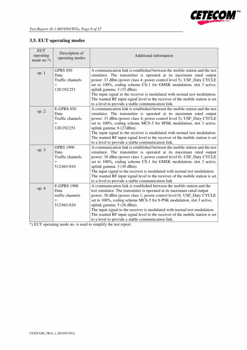
3.5. EUT operating modes
EUT
operating
mode no.*)
Description of
operating modes Additional information
op. 1 GPRS 850
Data
Traffic channels
=
128/192/251
A communication link is established between the mobile station and the test
simulator. The transmitter is operated at its maximum rated output
power: 33 dBm (power class 4; power control level 5). USF_Duty CYCLE
set to 100%, coding scheme CS-1 for GMSK modulation, slot 3 active,
uplink gamma: 3 (33 dBm).
The input signal to the receiver is modulated with normal test modulation.
The wanted RF input signal level to the receiver of the mobile station is set
to a level to provide a stable communication link.
op. 2 E-GPRS 850
Data
Traffic channels
=
128/192/251
A communication link is established between the mobile station and the test
simulator. The transmitter is operated at its maximum rated output
power: 33 dBm (power class 4; power control level 5). USF_Duty CYCLE
set to 100%, coding scheme MCS-5 for 8PSK modulation, slot 3 active,
uplink gamma: 6 (27dBm).
The input signal to the receiver is modulated with normal test modulation.
The wanted RF input signal level to the receiver of the mobile station is set
to a level to provide a stable communication link.
op. 3 GPRS 1900
Data
Traffic channels
=
512/661/810
A communication link is established between the mobile station and the test
simulator. The transmitter is operated at its maximum rated output
power: 30 dBm (power class 1; power control level 0). USF_Duty CYCLE
set to 100%, coding scheme CS-1 for GMSK modulation, slot 3 active,
uplink gamma: 3 (30 dBm).
The input signal to the receiver is modulated with normal test modulation.
The wanted RF input signal level to the receiver of the mobile station is set
to a level to provide a stable communication link
op. 4 E-GPRS 1900
Data
traffic channels
=
512/661/810
A communication link is established between the mobile station and the
test simulator. The transmitter is operated at its maximum rated output
power: 30 dBm (power class 1; power control level 0). USF_Duty CYCLE
set to 100%, coding scheme MCS-5 for 8-PSK modulation, slot 3 active,
uplink gamma: 5 (26 dBm).
The input signal to the receiver is modulated with normal test modulation.
The wanted RF input signal level to the receiver of the mobile station is set
to a level to provide a stable communication link.
*) EUT operating mode no. is used to simplify the test report.
Test Report 16-1-0019501T07a, Page 9 of 37
CETECOM_TR16_1_0019501T07a
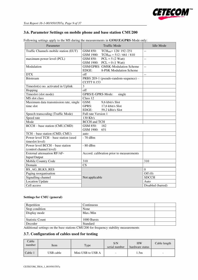
3.6. Parameter Settings on mobile phone and base station CMU200
Following settings apply to the MS during the measurements in GSM/(E)GPRS-Mode only:
Parameter Traffic Mode Idle Mode
Traffic Channels mobile station (EUT) GSM 850: TCHMS= 128/ 192 /251
GSM 1900: TCHMS = 512 / 661 / 810
--
maximum power level (PCL) GSM 850: PCL = 5 (2 Watt)
GSM 1900: PCL = 0 (1 Watt)
--
Modulation GSM/GPRS: GMSK-Modulation Scheme
EDGE: 8-PSK Modulation Scheme
--
DTX off --
Bitstream PRBS 2E9-1 (pseudo-random-sequence) –
CCITT 0.153
Timeslot(s) no. activated in Uplink 3
Hopping off
Timeslot (slot mode) GPRS/E-GPRS-Mode: single
MS slot class Class 12
Maximum data transmission rate, single
time slot
GSM: 9,6 kbit/s Slot
GPRS: 17,6 kbit/s Slot
EDGE: 59,2 kBit/s Slot
Speech transcoding (Traffic Mode) Full rate Version 1
Speed rate 130 Kb/s
Mode BCCH and TCH
BCCH – base station (CMU,CMD) GSM 850: 182
GSM 1900: 651
TCH – base station (CMD, CMU) auto
Power level TCH – base station (used
timeslot level)
- 70 dBm
Power level BCCH – base station
(control channel level)
- 80 dBm
External attenuation RF/AF-
Input/Output
Accord. calibration prior to measurements
Mobile Country Code 310 310
Domain CS
BS_AG_BLKS_RES
Not applicable
0
Paging reorganisation Off (0)
Signalling channel SDCCH
Location Update Auto
Cell access Disabled (barred)
Settings for CMU (general)
Repetition Continuous
Stop condition None
Display mode Max./Min
Statistic Count 1000 Bursts
Decoder Standard
Additional settings on the base stations CMU200 for frequency stability measurements
3.7. Configuration of cables used for testing
Cable
number Item Type S/N
serial number
HW
hardware status
Cable length
Cable 1 USB cable Mini-USB to USB A - 1.5m -

Test Report 16-1-0019501T07a, Page 10 of 37
CETECOM_TR16_1_0019501T07a
4. Description of test system set-up’s
4.1. Test system set-up for conducted measurements at antenna port
Cellular Conducted RF-Setup 1 (Cel-1 Set-up)
Tests Specification: Conducted spurious emissions, Emission Bandwidth
General Description: The EUT‘s RF-signal is coupled out by a suitable antenna coupling connector (1). The
signal is first attenuated (2) before it is 0° divided by a power divider (3). One of the RF-
signal path is connected to the test unit communication tester (4), other RF-path is
connected to the spectrum – analyzer (5) for specific RF-measurements. The specific
attenuation losses for both signal paths/branches are determined prior to the
measurement within a set-up calibration. These are then taken into account by correcting
the measurement readings on the spectrum-analyzer.
Schematic:
Used Equipment: Passive Elements Test Equipment Remark:
10 dB
Attenuator
(#530)
CMU200
Communication Test-
Unit for GSM/W-
CDMA
See List of equipment under each test
case and chapter 8 for calibration info
Low loss RF-
cables
DC-Power Supply
6 dB resistive
power
divider/coupler
(#529)
Spectrum-Analyser
Testing method: ANSI C63.10:2013, KDB 971168 D01 v02r02
Measurement uncertainty: See chapter Measurement Uncertainties (Cel-1)

Test Report 16-1-0019501T07a, Page 11 of 37
CETECOM_TR16_1_0019501T07a
Cellular Conducted RF-Setup 2 (Cel-2 Set-up)
Tests Specification: Conducted Carrier power, Frequency Error
Schematic: Following modified test set-up apply for tests performed inside the climatic chamber
(frequency stability) or conducted RF-carrier power-measurement. The EUT RF-Signal
is directly connected over suitable RF-connector over low-loss cable and an attenuator
(2) to the cellular radio communication test-unit. (5)
Testing method: ANSI C63.10:2013, KDB 971168 D01 v02r02
Used Equipment Passive Elements Test Equipment Remark:
20 dB
Attenuator
(#613)
CMU200
Communication Test-
Unit for GSM/W-CDMA
See List of equipment under each
test case and chapter 8 for
calibration info
Low loss RF-
cables
DC-Power Supply
Measurement uncertainty See chapter Measurement Uncertainties (Cel-2)

Test Report 16-1-0019501T07a, Page 12 of 37
CETECOM_TR16_1_0019501T07a
4.2. Test system set-up for radiated spurious emission measurements
Specification: ANSI C63.4-2014 chapter 8.3, ANSI C63.10-2013 chapter 6.6.3.3 & 6.6.4
General Description: Evaluating the emissions have to be done first by an exploratory emissions
measurement and a final measurement for most critical frequencies. The tests are
performed in a CISPR 16-1-4:2010 compliant fully anechoic room (FAR)
recognized by the regulatory commission. The measurement distance was set to 3
meter for frequencies up to 18 GHz and 2 meter above 18 GHz. A logarithmic
periodic antenna is used for the frequency range 30 MHz to 1 GHz. Horn antennas
are used for frequency range 1 GHz to 40 GHz. The EUT is aligned within 3 dB
beam width of the measurement antenna with three orthogonal axis measurements
on the EUT.
Schematic:
Testing method: Exploratory, preliminary measurements
The EUT and its associated accessories are placed
on a non-conductive position manipulator (tipping
device) of 1.50 m height which is placed on the
turntable. By rotating the turntable (range 0° to
360°, step 45°) and the EUT itself on 3-
orthogonal axis (the emission spectrum and it’s characteristics was recorded with an EMI-
receiver, broadband antenna and software.
The measurements are performed in horizontal
and vertical polarization of the measurement
antennas. The results are documented in a
diagram. Critical frequencies (low margin to
limit) are saved within a table for further
investigations. If various operating modes are
supported, further investigations are made to find
the worst-case of them. Also the interconnection
cables and equipment position were varied in
order to maximize the emissions.
Final measurement on critical frequencies
Based on the exploratory measurements, the most
critical frequencies are re-measured by main-
taining the EUT’s worst-case operation mode,
cable position, etc.
First a frequency zoom around the critical
frequency is done to locate the frequency more
precisely. After this step, for all identified critical
frequencies, the maximum peak was determined.
Following parameters were varied: the turntable
angle continuously in the range 0 to 360 degree,
the EUT itself over 3-orthogonal axis and the
height for EUT with large dimensions.
On the determined worst-case position, a final
measurement with necessary bandwidth and
detector according standard has been carried out.
The readings on the spectrum analyzer are
corrected with conversion value between field
strength and E(I)RP, so the readings shown are
equivalent to ERP/EIRP values. Critical
measurements near the limit are re-measured with
a substitution method accord. ANSI/TIA/EIA 603
C/D Formula: EC = ER + AF + CL + DF - GA (1) EC = Electrical field – corrected value
ER = Receiver reading
EcE(I)RP = Ec - 95.2 dB M = Margin
LT = Limit
M = LT - EcE(I)RP AF = Antenna factor
CL = Cable loss
DF = Distance correction factor (if used)
GA = Gain of pre-amplifier (if used)
EcE(I)RP = Electrical field corrected for E(I)RP
All units are dB-units, positive margin means value is below limit.

Test Report 16-1-0019501T07a, Page 13 of 37
CETECOM_TR16_1_0019501T07a
5. Measurements
5.1. RF-Parameter - RF Peak power output conducted and PAPR-value
5.1.1. Test location and equipments test location CETECOM Essen (Chapter. 2.2.1) Please see Chapter. 2.2.2
test site 347 Radio.lab. 1 Radio.lab. 2
spectr. analys. 584 FSU 489 ESU 40 264 FSEK 620 ESU 26
signaling 392 MT8820A 436 CMU 547 CMU
otherwise 110 USB LWL
DC power 456 EA 3013A 463 HP3245A 459 EA 2032-50 268 EA- 3050 494 AG6632A 498 NGPE 40
otherwise 331 HC 4055 248 6 dB Att. 529 Power div. - cable OTA20
line voltage 230 V 50 Hz via public mains 060 120 V/ 60 Hz via PAS 5000
5.1.2. Requirements and limits
FCC §2.1046(a)
IC RSS-132 : 5.4 + SRSP 503 :5.1.3 for GSM 850
RSS-133 4.1/6.4 + SRSP-510 :5.1.2 for GSM 1900
ANSI C63.26-2015, Chapter 5.2
Limit
Maximum conducted output power of the transmitter should be determined while measured on RF output terminal.
Limit GSM850: 7 Watt (38.4 dBm)
Limit GSM1900: 2 Watt (33.0 dBm)
PAPR≤13 dB
5.1.3. Test condition and test set-up Climatic conditions Temperature: (22±3°C) Rel. humidity: (40±20)%
Test system set-up Please see chapter “Test system set-up for conducted measurements on antenna port”
Measurement method
The measurements were performed with the integrated power measurement function of the „radio communication tester CMU200 from Rohde&Schwarz company. In this way spectrum-analyzers
instrument limitations can be avoided or minimized. Instead, CMU manufacturers declared
measurement error can be considered for this measurement.
The attenuation (insertion loss) at the RF Inputs/Outputs of CMU were set according the path loss
of the test set-up, determined in a step before starting the measurements. A suitable artificial antenna
or RF-connector is provided by the applicant in order to perform the conducted measurements. Any
data provided with the artificial antenna or connector, have been taken in account in order to correct
the measurement data. (typical 0.3dB for attenuation of antenna connector)
Peak and Average Values have been recorded for each channel on test set-up Cel-1. The Peak-to -
Average-Power Ratio is determined by devices integrated CCDF capability with corresponding
settings. (see annex 1 plots) The guideline in ANSIC63.26-2016 is taken into account.
Mobile phone settings
A call was established with settings according chapter “Parameter settings on mobile phone and base
station CMU200”
UE Power should be set to maximum, continuous transmission. DTX or other power saving
techniques have been disabled
The measurements were made at the low, middle and high carrier frequencies of each of the supported
operating band. Choosing three TX-carrier frequencies of the mobile phone, should be sufficient to
demonstrate compliance.

Test Report 16-1-0019501T07a, Page 14 of 37
CETECOM_TR16_1_0019501T07a
5.1.4. Measurement results
Op. Mode 1, Set-up 1
Op. Mode
Carrier Channel
Peak
Output
Power
[dBm]
Average
Output
Power
[dBm]
PAPR-
Ratio on
0.1%
probability
[dB]
Peak
power
Limit
PAPR-
Limit
Result
Range No. [dBm] [dB]
GSM 850
Low 128 32.7 32.5 0.34
38.4 13 Passed Middle 192 32.8 32.6 0.34
High 251 32.7 32.6 0.32
Remark: --
Op. Mode 2, Set-up 1
Op. Mode
Carrier Channel Peak
Output
Power
[dBm]
Average
Output
Power
[dBm]
PAPR-
Ratio on
0.1%
probability
[dB]
Peak
power
Limit
PAPR-
Limit
Result
Range No. [dBm] [dB]
E-GPRS 850
Low 128 29.9 27.2 3.37
38.4 13 Passed Middle 192 30.0 27.3 3.30
High 251 30.0 27.3 3.49
Remark: --
Op. Mode 3, Set-up 1
Op. Mode
Carrier Channel Peak
Output
Power
[dBm]
Average
Output
Power
[dBm]
PAPR-
Ratio on
0.1%
probability
[dB]
Peak
power
Limit
PAPR-
Limit
Result
Range No. [dBm] [dB]
GSM 1900
Low 512 29.9 29.8 0.26
38.4 13 Passed Middle 661 29.9 29.7 0.26
High 810 29.9 29.8 0.27
Remark: --
Op. Mode 4, Set-up 1
Op. Mode
Carrier Channel
Peak
Output
Power
[dBm]
Average
Output Power
[dBm]
PAPR-
Ratio on
0.1%
probability
[dB]
Peak
power
Limit
PAPR-
Limit
Result
Range No. [dBm] [dB]
E-GPRS
1900
Low 512 29.0 26.1 3.55
33.0 13 Passed Middle 661 29.0 26.1 3.38
High 810 29.0 26.2 3.18
Remark: --

Test Report 16-1-0019501T07a, Page 15 of 37
CETECOM_TR16_1_0019501T07a
5.2. RF-Parameter - Occupied bandwidth and emission bandwidth
5.2.1. Test location and equipments (for reference numbers please see chapter 'List of test equipment')
test site 347 Radio.lab. 1 Radio.lab. 2
spectr. analys. 584 FSU 489 ESU40 264 FSEK 620 ESU26
signaling 392 MT8820A 436 CMU 547 CMU
DC Power 463 HP3245A 087 EA3013 354 NGPE 40 086 LNG50-10
otherwise 529 6dB divider 530 10dB Att. 431 Near field
line voltage 230 V 50 Hz via public mains 060 120 V/ 60 Hz via PAS 5000
5.2.2. Requirements and Limits
FCC §2.202(a), §2.1049(h), §22.917(b), §24.238(b) „the occupied bandwidth is the frequency
bandwidth, such that, below it lower and
above it upper frequency limits, the mean
powers radiated are each equal to 0.5 percent
of the total mean power radiated”
IC RSS-Gen, Issue 4: §6.6
ANSI C63.26-2015, Chapter 5.4
5.2.3. Test condition and test set-up Climatic conditions Temperature: (22±3°C) Rel. humidity: (40±20)%
Test system set-up Please see chapter “Test system set-up for conducted measurements at antenna port”
Spectrum
Analyzer
Settings
Parameter Occupied bandwidth: Emission bandwidth
Scan Mode
Span
RBW
VBW
Sweep time
Sweep mode
Detector
Spectrum analyser mode
1 MHz
3 kHz
30 kHz
Coupled
Repetitive, max-hold
Peak
Spectrum analyser mode
1 MHz
3 kHz
30 kHz
Coupled
Repetitive, max-hold
Peak
Measurement method
The used spectrum analyzer FSE or ESU from Rohde & Schwarz
contains an integrated function to calculate the occupied bandwidth
automatically. From left and right display margin, the upper and
lower frequency points where the accumulated power becomes 0.5%
of the total power, are calculated. Subtracting the previous
determined two frequency points, yields the occupied bandwidth.
Bandwidth defined between 2
markers with are 26dBc compared to
highest In-Band Peak Emission.
EUT settings
Provisions with the requirements is based on the fact, that GSM modulation scheme is GMSK Modulation
for GSM equipment with a maximum data transmission rate of 17,6 kBit/s per Slot. Provisions with the
requirements is based on the fact, that EDGE modulation scheme is 8-PSK Modulation for EDGE
equipment with a maximum data transmission rate of 69,2 kBit/s per Slot. A call was established with
settings according chapter “Parameter settings on wireless device and base station CMU200”
5.2.4. Measurement results
Operating mode/band
Set-up
Carrier Channel Occupied 99%
bandwidth
[kHz]
26 dBc Emission
bandwidth
[kHz] Range No.
Set-up 2, Op-Mode 1
GSM 850
Low 128 241.987179487 314.102564103
Middle 192 243.589743590 318.910256410
High 251 245.192307692 315.705128205
Set-up 2, Op-Mode 2
E-GPRS 850
Low 128 250.0 323.717948718
Middle 192 250.0 322.115384615
High 251 248.397435897 323.717948718
Set-up 2, Op-Mode 3
GSM 1900
Low 512 243.58974359 312.5
Middle 661 243.58974359 312.5
High 810 245.192307692 317.307692307
Set-up 2, Op-Mode 4
E-GPRS 1900
Low 512 250.0 325.32051282
Middle 661 253.205128205 315.705128205
High 810 243.8397435897 317.307692307
Remarks: see annex1/diagrams

Test Report 16-1-0019501T07a, Page 16 of 37
CETECOM_TR16_1_0019501T07a
5.3. RF-Parameter - Conducted out of Band RF emissions and Band Edge
5.3.1. Test location and equipments (for reference numbers please see chapter 'List of test equipment') test location CETECOM Essen (Chapter. 2.2.1) Please see Chapter. 2.2.2 Please see Chapter. 2.2.3
test site 347 Radio.lab. 1 Radio.lab. 2
spectr. analys. 584 FSU 120 FSEM 264 FSEK 489 ESU 620 ESU26
signaling 017 CMD 65 323 CMD 55 340 CMD 55
signaling 392 MT8820A 436 CMU 547 CMU
power supply 463 HP3245A 457 EA 3013A 459 EA 2032-50 268 EA- 3050 494 AG6632A 498 NGPE 40
otherwise 529 6dB divider 530 10dB Att. 431 Near field
line voltage 230 V 50 Hz via public mains 060 120 V/ 60 Hz via PAS 5000
5.3.2. Requirements and limits
FCC
Part 2.1051, Part2.1057(a)(1)
Part 22 Subpart H, §22.917(a)(b)(c)(d)
Part 24 Subpart E, §24.238(a)(b)(c)(d)
IC RSS-132, Issue 3: 5.5(i)(ii)
RSS-133, Issue 6: 6.5.1(i)(ii)
ANSI C63.26-2015, Chapter 5.7
Limit
§22.917(a) & §24.238(a):
“The power of any emission outside of the authorized operating frequency ranges must be attenuated below the transmitting power (P) by a factor of at least 43 + 10 log(P) dB”
Resulting Limit of-13dBm for all Power Control Levels of the cellular equipment
5.3.3. Test condition and test set-up Climatic conditions Temperature: (22±3°C) Rel. humidity: (40±20)%
Test system set-up Please see chapter “Test system set-up for conducted measurements on antenna port”
Measurement method
Ҥ 2.1057 Frequency spectrum to be investigated. (a) In all of the measurements set forth in
§ 2.1051 and 2.1053, the spectrum shall be investigated from the lowest radio frequency signal
generated in the equipment, without going below 9 kHz”
The spectrum was scanned from 9 kHz (depend on the equipment, s. §2.1057) to the 10th harmonic
of the highest frequency generated within the equipment. A PEAK detector was used except
measurements near the block-edge where also a AVERAGE detector can be applied.
A suitable artificial antenna or RF-connector is provided by the applicant in order to perform the
conducted measurements. Any data provided with the artificial antenna or connector, have been
taken in account in order to correct the measurement data. (typical 0.3dB for attenuation of
antenna connector) Spectrum-Analyzer settings See below tables
EUT settings
A call was established with settings according chapter “Parameter settings on mobile phone and base station CMU200”
UE Power should be set to maximum, continuous transmission. DTX or other power saving
techniques have been disabled.
The measurements were made at the low, middle and high carrier frequencies of each of the
supported operating band. Choosing three TX-carrier frequencies of the wireless device, should be
sufficient to demonstrate compliance.
5.3.4. Spectrum-Analyzer settings for GSM/GPRS/E-GPRS 850
Sweep No.
Start
freq.
MHz
Stop
freq.
MHz
R-BW
MHz
V-BW
MHz
Sweep
time
sec.
Att.
[dB] Detector
Sweep 1 (subrange 1) 0.009 1 0.001 0.01 10 25 PK or RMS
Sweep 1 (subrange 2) 1 30 0.1 1 5 25 PK or RMS
Sweep 2 (subrange 1) 30 820 1 10 10 35 PK or RMS
Sweep 2 (subrange 2) 820 1000 1 10 2 45 PK or RMS
Sweep 2 (subrange 3) 1000 9000 1 10 100 35 PK or RMS
Sweep 3a (Band-Edge) 823 824 0.003 0.01 70 35 PK or RMS
Sweep 4a (Band-Edge) 849 850 0.003 0.01 70 35 PK or RMS

Test Report 16-1-0019501T07a, Page 17 of 37
CETECOM_TR16_1_0019501T07a
5.3.5. Spectrum-Analyzer Settings GSM/GPRS/E-GPRS 1900
Start
freq.
MHz
Stop
freq.
MHz
R-BW
MHz
V-BW
MHz
Sweep
time
sec.
Att. Detector
Sweep 1 (subrange 1) 0.009 1 0.001 0.01 10 25 PK or RMS
Sweep 1 (subrange 2) 1 30 0.1 1 5 25 PK or RMS
Sweep 2 (subrange 1) 30 1000 1 10 100 35 PK or RMS
Sweep 2 (subrange 2) 1000 2500 1 10 15 35 PK or RMS
Sweep 2 (subrange 3) 2500 19500 1 10 150 35 PK or RMS
Sweep 3a (Band-Edge) 1849 1850 0.003 0.01 70 35 PK or RMS
Sweep 4a (Band-Edge) 1910 1911 0.003 0.01 70 35 PK or RMS
5.3.6. Results
The results are presented below in summary form only. For more information please see each diagram
enclosed in annex 1 diagrams.
5.3.7. GPRS 850: Set-up 2
Diagram no.
Carrier
Channel Frequency
range
OP-
mode
no.
Remark Used detector
Result
Range No. PK AV QP
36.07_CH128_GPRS_Sweep1 Low
128
9 kHz –
30 MHz
1
-- passed
36.08_CH128_GPRS_Sweep2 Low 30MHz –
9 GHz
Carrier visible on diagram,
not relevant for result passed
37.03_BE_CH128_GPRS Low 823-824
MHz Band Edge Compliance passed
36.09_CH192_GPRS_Sweep1 Middle
192
9 kHz –
30 MHz -- passed
36.10_CH192_GPRS_Sweep2 Middle 30MHz –
9 GHz
Carrier visible on diagram,
not relevant for result passed
36.11_CH251_GPRS_Sweep1 High
251
9 kHz –
30 MHz -- passed
36.12_CH251_GPRS_Sweep2 High 30MHz –
9 GHz
Carrier visible on diagram,
not relevant for result passed
37.04_BE_CH251_GPRS High 849 – 850
MHz Band-Edge compliance passed
Remark:--

Test Report 16-1-0019501T07a, Page 18 of 37
CETECOM_TR16_1_0019501T07a
5.3.8. E-GPRS 850: Set-up 2
Diagram no.
Carrier
Channel Frequenc
y range
OP-
mode
no.
Remark Used detector
Result
Range No. PK AV QP
36.13_Ch128_EGPRS_Sweep1 Low
128
9 kHz –
30 MHz
2
-- passed
36.14_Ch128_EGPRS_Sweep2 Low 30MHz –
9 GHz
Carrier visible on diagram,
not relevant for result passed
37.05_BE_Ch128_EGPRS Low 823 - 824
MHz Band Edge Compliance passed
36.15_Ch192_EGPRS_Sweep1 Middle
192
9 kHz –
30 MHz -- passed
36.16_Ch192_EGPRS_Sweep2 Middle 30MHz –
9 GHz
Carrier visible on diagram,
not relevant for result passed
36.17_Ch251_EGPRS_Sweep1 High
251
9 kHz –
30 MHz -- passed
36.18_Ch251_EGPRS_Sweep2 High 30MHz –
9 GHz
Carrier visible on diagram,
not relevant for result passed
37.06_BE_Ch251_EGPRS High 849 – 850
MHz Band-Edge compliance passed
Remark:--
5.3.9. GPRS 1900: Set-up 2
Diagram no.
Carrier
Channel Frequency
range
OP-
mode
no.
Remark Used detector
Result
Range No. PK AV QP
36.20_RSE_Ch512_GPRS_Sweep1 Low
512
9 kHz –
30 MHz
3
-- passed
36.21_RSE_Ch512_GPRS_Sweep2 Low 30MHz –
20 GHz
Carrier visible on diagram,
not relevant for result passed
37.10_BE_Ch512_GPRS_PK Low 1849 –
1850 MHz Band Edge Compliance passed
36.22_RSE_Ch661_GPRS_Sweep1 Middle 661
9 kHz –
30 MHz -- passed
36.23_RSE_Ch661_GPRS_Sweep2 Middle 30MHz –
20 GHz
Carrier visible on diagram,
not relevant for result passed
36.24_RSE_Ch810_GPRS_Sweep1 High
810
9 kHz –
30 MHz -- passed
36.25_RSE_Ch810_GPRS_Sweep2 High 30MHz –
20 GHz
Carrier visible on diagram,
not relevant for result passed
37.11_BE_Ch810_GPRS_PK High 1910 –
1911 MHz Band-Edge compliance passed
Remark: --

Test Report 16-1-0019501T07a, Page 19 of 37
CETECOM_TR16_1_0019501T07a
5.3.10. E-GPRS 1900: Set-up 2
Diagram no.
Carrier
Channel Frequency
range
OP-
mode
no.
Remark Used detector
Result
Range No. PK AV QP
36.26_RSE_Ch512_EGPRS_Sweep
1 Low
512
9 kHz –
30 MHz
4
-- passed
36.27_RSE_Ch512_EGPRS_Sweep
2 Low
30MHz –
20 GHz
Carrier visible on diagram,
not relevant for result passed
37.12_BE_Ch512_EGPRS_PK Low 1849 –
1850 MHz Band Edge Compliance passed
36.28_RSE_Ch661_EGPRS_Sweep
1 Middle
661
9 kHz –
30 MHz -- passed
36.29_RSE_Ch661_EGPRS_Sweep
2 Middle
30MHz –
20 GHz
Carrier visible on diagram,
not relevant for result passed
36.30_RSE_Ch810_EGPRS_Sweep
1 High
810
9 kHz –
30 MHz -- passed
36.31_RSE_Ch810_EGPRS_Sweep
2 High
30MHz –
20 GHz
Carrier visible on diagram,
not relevant for result passed
37.13_BE_Ch810_EGPRS_PK High 1910 –
1911 MHz Band-Edge compliance passed
Remark: --

Test Report 16-1-0019501T07a, Page 20 of 37
CETECOM_TR16_1_0019501T07a
5.4. RF-Parameter - Frequency stability on temperature and voltage variations
5.4.1. Test location and equipments (for reference numbers please see chapter 'List of test equipment') test location CETECOM Essen (Chapter. 2.2.1) Please see Chapter. 2.2.2 Please see Chapter. 2.2.3
test site 347 Radio.lab.1 Radio.lab.2
spectr. analys. 584 FSU 489 ESU 40 264 FSEK 620 ESU 26
signaling 392 MT8820A 436 CMU 547 CMU
DC power 456 EA 3013A 457 EA 3013A 459 EA 2032-50 268 EA- 3050 494 AG6632A 498 NGPE 40
otherwise 529 6dB divider 530 10dB Att. 431 Near field
Climatic test
chamber 331 HC 4055 627 OPUS 1
line voltage 230 V 50 Hz via public mains 060 120 V/ 60 Hz via PAS 5000
5.4.2. Requirements and limits
FCC
§2.1055(a)(1) (d)
§22.355
§24.235
IC
RSS-Gen, Issue 3
RSS-132: 5.3
RSS-133: 6.3
ANSI C63.26-2015, Chapter 5.6
Limit “The frequency stability shall be sufficient to ensure that the fundamental emission stays within the authorized frequency block”
5.4.3. Test condition and test set-up
Test system set-up
Please see chapter “Test system set-up for conducted measurements on antenna port”
In order to maintain the voltage constant over the time period of the tests, a dummy battery was
connected to a laboratory power supply. The power supply voltage was controlled on the input of
the power supply terminals of the EUT under operating conditions.
Measurement method
The GSM RF Channel spacing is 200 kHz according GSM-Spec, with a guard band of 200 kHz of
each band of the sub-bands. The purpose of the EUT is to function under all extreme conditions within
authorized sub-bands in regard to temperature and voltage variations. The frequency deviation was
recorded with base station’s build in capability. (CMU)
As the standard requires that the fundamental emissions stays within the authorized band, a limit of
0.1ppm is considered low enough to ensure this.
EUT settings
A call was established with settings according chapter “Parameter settings on mobile phone and base station CMU200”
The measurements were made at the low, middle and high carrier frequencies of each of the supported
operating band. Choosing three TX-carrier frequencies of the wireless device , should be sufficient
to demonstrate compliance.
5.4.4. Measurement results
5.4.4.1. Frequency shift of carrier against a voltage range at constant nominal temperature of 20° Celsius
1.) determine the carrier frequency for the lowest and highest channel at room temperature and nominal
voltage [20°C]
2.) The voltage was reduced in 0.1 Volt steps to the lower end point, where the mobile phone stops working.
(this shall be specified by the manufacturer) Record the carrier frequency shift within 2 minutes after
powering on the mobile phone, to prevent for self heating effects.
3.) The voltage was increased in 0.1 Volt steps to the upper declared voltage of the battery. Record the
carrier frequency shift within 2 minutes after powering on the mobile phone, to prevent for self heating
effects.

Test Report 16-1-0019501T07a, Page 21 of 37
CETECOM_TR16_1_0019501T07a
5.4.4.2. GPRS 850 Mode: Op. Mode 1, set-up 2
5.4.4.3. E-GPRS 850 Mode: Op. Mode 2, set-up 2
[Hz] [ppm]
3,3 13 0,016
3,4 14 0,017
3,5 16 0,019
3,6 16 0,019
3,7 15 0,018
3,8 14 0,017
3,9 13 0,016
4,0 14 0,017
4,1 13 0,016
4,2 13 0,016
4,3 12 0,014
4,4 13 0,016
Voltage
[V]
Maximum frequency error
passed8,37E+08
Verdict
Limit=+/-0.1ppm
Nominal
Frequency
[MHz]
Channel 192: GMSK
Verdict
[Hz] [ppm] Limit= +/-0.1ppm
3,3 -22 -0,026
3,4 -20 -0,024
3,5 -26 -0,031
3,6 -23 -0,027
3,7 -23 -0,027
3,8 -23 -0,027
3,9 -24 -0,029
4,0 -20 -0,024
4,1 -20 -0,024
4,2 -23 -0,027
4,3 -23 -0,027
4,4 -24 -0,029
Voltage
[V]
Channel 192: 8-PSKNominal
Frequency
[MHz]
8,37E+08
Maximum frequency error
passed

Test Report 16-1-0019501T07a, Page 22 of 37
CETECOM_TR16_1_0019501T07a
5.4.4.4. GPRS 1900 Mode: Op. Mode 3, set-up 2
5.4.4.5. E-GPRS 1900 Mode: Op. Mode 4, set-up 2
Verdict
[Hz] [ppm] Limit= +/-0.1ppm
3,3 19 0,010
3,4 19 0,010
3,5 -21 -0,011
3,6 -25 -0,013
3,7 -21 -0,011
3,8 -24 -0,013
3,9 -20 -0,011
4,0 -21 -0,011
4,1 -21 -0,011
4,2 -18 -0,010
4,3 -22 -0,012
4,4 -20 -0,011
1,88E+09 passed
Voltage
[V]
Nominal
Frequency
[MHz]
Maximum frequency error
Channel 661: GMSK
Verdict
[Hz] [ppm] Limit= +/-0.1ppm
3,3 -38 -0,020
3,4 -33 -0,018
3,5 -33 -0,018
3,6 -40 -0,021
3,7 -37 -0,020
3,8 -37 -0,020
3,9 -40 -0,021
4,0 -33 -0,018
4,1 -39 -0,021
4,2 -35 -0,019
4,3 -34 -0,018
4,4 -38 -0,020
Voltage
[V]
Nominal
Frequency
[MHz]
Maximum frequency error
1,88E+09 passed
Channel 661: 8-PSK

Test Report 16-1-0019501T07a, Page 23 of 37
CETECOM_TR16_1_0019501T07a
5.4.4.6. Frequency shift of carrier against temperature at constant power supply voltage
1.) determine the carrier frequency for the lowest, middle and highest channel at room temperature and nominal
voltage [20°C]
2.) expose the mobile station to –30°C, wait sufficient time to have constant temperature.
3.) Perform the carrier frequencies measurements in 10°C increments from –30°C to +60°C. For about half hour
at the specified temperature the mobile was powered-off. After powering-on, the measurements were made
within 2 minute for the channel lower channel, in order to prevent self-warming of the mobile.
5.4.4.6.1. GPRS 850 Mode: Op. Mode 1, set-up 2
Channel
128
Channel
192
Channel
251
Channel
128
Channel
192
Channel
251
-30 16 19 16 0,019 0,023 0,019
-20 18 21 16 0,022 0,025 0,019
-10 13 16 14 0,016 0,019 0,016
0 13 11 11 0,016 0,013 0,013
10 15 15 16 0,018 0,018 0,019
20 12 14 13 0,015 0,017 0,015
30 14 24 25 0,017 0,029 0,029
40 14 16 20 0,017 0,019 0,024
50 13 13 14 0,016 0,016 0,016
Temperature
Verdict
Limit=±0.1ppm
Passed
Maximum frequency error
[Hz] [ppm]

Test Report 16-1-0019501T07a, Page 24 of 37
CETECOM_TR16_1_0019501T07a
5.4.4.6.2. E-GPRS 850 Mode: Op. Mode 2, set-up 2
Channel
128
Channel
192
Channel
251
Channel
128
Channel
192
Channel
251
-30 -18 -21 -24 -0,022 -0,025 -0,028
-20 -18 -20 -22 -0,022 -0,024 -0,026
-10 -14 -19 -18 -0,017 -0,023 -0,021
0 -23 -20 -18 -0,028 -0,024 -0,021
10 -23 -26 -21 -0,028 -0,031 -0,025
20 -22 -23 -23 -0,027 -0,027 -0,027
30 -21 -24 -22 -0,025 -0,029 -0,026
40 -21 -19 -17 -0,025 -0,023 -0,020
50 -22 -18 -16 -0,027 -0,022 -0,019
Temperature
Passed
Maximum frequency errorVerdict
Limit=±0.1ppm[Hz] [ppm]

Test Report 16-1-0019501T07a, Page 25 of 37
CETECOM_TR16_1_0019501T07a
5.4.4.6.3. GPRS 1900 Mode: Op. Mode 3, set-up 2
Channel
512
Channel
661
Channel
810
Channel
512
Channel
661
Channel
810
-30 30 26 24 0,016 0,014 0,013
-20 28 20 20 0,015 0,011 0,010
-10 22 19 17 0,012 0,010 0,009
0 21 -22 -19 0,011 -0,012 -0,010
10 -21 -23 -21 -0,011 -0,012 -0,011
20 21 -24 -23 0,011 -0,013 -0,012
30 22 -20 -21 0,012 -0,011 -0,011
40 -21 19 20 -0,011 0,010 0,010
50 23 22 -19 0,012 0,012 -0,010
Temperature
Passed
Maximum frequency errorVerdict
Limit=±0.1ppm[Hz] [ppm]

Test Report 16-1-0019501T07a, Page 26 of 37
CETECOM_TR16_1_0019501T07a
5.4.4.6.4. E-GPRS 1900 Mode: Op. Mode 4, set-up 2
Channel
512
Channel
661
Channel
810
Channel
512
Channel
661
Channel
810
-30 -31 -37 -38 -0,017 -0,020 -0,020
-20 -30 -37 -37 -0,016 -0,020 -0,019
-10 -31 -33 -28 -0,017 -0,018 -0,015
0 -36 -33 -37 -0,019 -0,018 -0,019
10 -35 -38 -36 -0,019 -0,020 -0,019
20 -33 -37 -35 -0,018 -0,020 -0,018
30 -35 -40 -34 -0,019 -0,021 -0,018
40 -34 -32 -39 -0,018 -0,017 -0,020
50 -30 -30 -36 -0,016 -0,016 -0,019
Temperature
Passed
Maximum frequency errorVerdict
Limit=±0.1ppm[Hz] [ppm]

Test Report 16-1-0019501T07a, Page 27 of 37
CETECOM_TR16_1_0019501T07a
5.5. RF-Parameter - Radiated out of Band RF emissions and Band Edge 5.5.1. Test location and equipments (for reference numbers please see chapter 'List of test equipment') test location CETECOM Essen (Chapter. 2.2.1) Please see Chapter. 2.2.2 Please see Chapter. 2.2.3
test site 441 EMI SAR 487 SAR NSA 443 FAR 347 Radio.lab.1 Radio.lab.2
receiver 377 ESCS30 001 ESS 489 ESU 40 620 ESU 26
spectr. analys. 584 FSU 120 FSEM 264 FSEK
antenna 439 HL 562 549 HL 025 302 BBHA9170 289 CBL 6141 030 HFH-Z2 477 GPS
signaling 017 CMD 65 323 CMD 55 340 CMD 55
signaling 392 MT8820A 546 CMU 547 CMU
power supply 463 HP3245A 457 EA 3013A 459 EA 2032-50 268 EA- 3050 494 AG6632A 498 NGPE 40
otherwise 529 6dB divider 530 6dB Att. 110 USB LWL 482 Filter Matrix 431 Near field
line voltage 230 V 50 Hz via public mains 060 120 V/ 60 Hz via PAS 5000
5.5.2. Requirements and limits (Variante RF-Parameter)
FCC
Part 2.1053(a), Part2.1057(a)(1)
Part 22 Subpart H, §22.917(a)(b)
Part 24 Subpart E, §24.238(a)(b)
IC RSS-132, Issue 3: 5.5(i)(ii)
RSS-133, Issue 6: 6.5.1(i)(ii)
Limit
§22.917(a) & §24.238(a):
“The power of any emission outside of the authorized operating frequency ranges must be attenuated below the transmitting power (P) by a factor of at least 43 + 10 log(P) dB”
Limit: -13dBm for all Power Control Levels of the cellular equipment
5.5.3. Test condition and test set-up link to test system (if used): air link cable connection
EUT-grounding none with power supply additional connection
Equipment set up table top floor standing
Climatic conditions Temperature: (22±3°C) Rel. humidity: (40±20)%
Test system set-up Please see chapter “Test system set-up for radiated spurious emission measurements up to 20
GHz”
Measurement method
Ҥ 2.1057 Frequency spectrum to be investigated. (a) In all of the measurements set forth in
§ 2.1051 and 2.1053, the spectrum shall be investigated from the lowest radio frequency signal
generated in the equipment, without going below 9 kHz”
The spectrum was scanned from 9 kHz (depend on the equipment, s. §2.1057) to the 10th harmonic
of the highest frequency generated within the equipment. A PEAK detector was used except
measurements near the block-edge where a AVERAGE detector applied.
According chapter “Test system set-up for electric field measurement in the range 30-1000MHz and
1 to 40GHz” and additionally: the readings on the spectrum analyzer are corrected with annually
performed chamber path calibration values so the readings shown are equivalent to ERP/EIRP
values. Critical measurements near the limit are re-measured with a substitution method accord.
ANSI/TIA/EIA 603 and ANSI C63.26-2015
EUT settings
A call was established with settings according chapter “Parameter settings on mobile phone and base station CMU200”
The UE and used accessories (if any used) were set to work according their intended
use/specification stated as by the applicant
The measurements were made at the low, middle and high carrier frequencies of each of the
supported operating band. Choosing three TX-carrier frequencies of the wireless device, should be
sufficient to demonstrate compliance.

Test Report 16-1-0019501T07a, Page 28 of 37
CETECOM_TR16_1_0019501T07a
Spectrum-Analyzer settings for GSM/GPRS/E-GPRS 850 Mode
Sweep no.
Start
freq.
MHz
Stop
freq.
MHz
R-BW
MHz
V-BW
MHz
Sweep
time
sec.
Att.
[dB] Detector
Sweep 1 (subrange 1) 30 1000 1 1 10 10 MaxH-PK
Sweep 2 (subrange 2) 1000 2800 1 1 15 10 MaxH-PK
Sweep 3 (subrange 3) 2800 9000 1 1 60 10 MaxH-PK
Sweep 4a (Band-Edge) 823 824 0.003 0.01 30 10 MaxH-PK
Sweep 4b (Band-Edge) 849 850 0.003 0.01 30 10 MaxH-PK
Spectrum-analyzer settings for GSM/GPRS/E-GPRS 1900 Mode
Sweep no.
Start
freq.
MHz
Stop
freq.
MHz
R-BW
MHz
V-BW
MHz
Sweep
time
sec.
Att. Detector
Sweep 1 (subrange 1) 30 1000 1 1 10 10 MaxH-PK
Sweep 2 (subrange 2) 1000 2800 1 1 15 10 MaxH-PK
Sweep 3 (subrange 3) 2800 20000 1 1 160 10 MaxH-PK
Sweep 4a (Band-Edge) 1849 1850 0.003 0.01 30 10 MaxH-PK
Sweep 4b (Band-Edge) 1910 1911 0.003 0.01 30 10 MaxH-AV
5.5.4. Measurement results
The results are presented below in summary form only. For more information please see each diagram enclosed
in annex 4.
5.5.4.1. GPRS 850: Set-up 1
Diagram
no.
Carrier Channel Frequency
range
OP-
mode
no.
Remark Used detector
Result
Range No. PK AV QP
8.04_RSE_R_Ch128_GPRS Low
128
30 MHz –
9 GHz
1
Carrier on diagram, not
relevant for results passed
9.03_RSE_R_Ch128_GPRS Low 823 – 824
MHz Band Edge Compliance passed
8.05_RSE_R_Ch192_GPRS Middle 192 30 MHz –
9 GHz
Carrier on diagram, not
relevant for results passed
8.06_RSE_R_Ch251_GPRS High 251
30 MHz –
9 GHz
Carrier on diagram, not
relevant for results passed
9.04_RSE_R_Ch251_GPRS High 849 –
850 MHz Band-Edge compliance passed
Remark:--

Test Report 16-1-0019501T07a, Page 29 of 37
CETECOM_TR16_1_0019501T07a
5.5.4.2. GPRS 1900: Set-up 1
Diagram
no.
Carrier
Channel Frequency
range
OP-
mode
no.
Remark Used detector
Result
Range No. PK AV QP
8.13_RSE_R_Ch512_GPRS Low
512
30 MHz – 18
GHz
3
Carrier on diagram, not
relevant for results passed
9.09_BE_R_Ch512_GPRS Low 1849 – 1850
MHz Band Edge Compliance passed
8.14_RSE_R_Ch661_GPRS Middle 661 30 MHz – 18
GHz
Carrier on diagram, not
relevant for results passed
8.15_RSE_R_Ch810_PRS High 810
30 MHz – 18
GHz
Carrier on diagram, not
relevant for results passed
9.10_BE_R_Ch810_GPRS High 1910 – 1911
MHz Band-Edge compliance passed
Remark:--
5.5.4.3. E-GPRS 1900: Set-up 1
Diagram
no.
Carrier
Channel Frequency
range
OP-
mode
no.
Remark Used detector
Result
Range No. PK AV QP
-- --
512
30 MHz –18
GHz
4
-- --
9.11_BE_R_Ch512_EGPRS Low 1849 – 1850
MHz Band Edge Compliance passed
-- -- 661 30 MHz – 18
GHz -- --
-- -- 810
30 MHz – 18
GHz -- --
9.12_BE_R_Ch810_EGPRS High 1910 – 1911
MHz Band-Edge compliance passed
Remark: due critical results in GRPS1900 Mode also tests in E-GPRS 1900MHz mode

Test Report 16-1-0019501T07a, Page 30 of 37
CETECOM_TR16_1_0019501T07a
5.6. General Limit - Radiated field strength emissions below 30 MHz
5.6.1. Test location and equipment test location CETECOM Essen (Chapter. 2.2.1) Please see Chapter. 2.2.2 Please see Chapter. 2.2.3
test site 441 EMI SAR 487 SAR NSA 347 Radio.lab.
receiver 377 ESCS30 001 ESS
spectr. analys. 584 FSU 120 FSEM 264 FSEK
antenna 574 BTA-L 133 EMCO3115 302 BBHA9170 289 CBL 6141 030 HFH-Z2 477 GPS
signaling 392 MT8820A 371 CBT32 547 CMU 594 CMW
otherwise 400 FTC40x15E 401 FTC40x15E 110 USB LWL 482 Filter Matrix 378 RadiSense
DC power 456 EA 3013A 457 EA 3013A 459 EA 2032-50 268 EA- 3050 494 AG6632A 498 NGPE 40
line voltage 230 V 50 Hz via public mains 060 120 V 60 Hz via PAS 5000
5.6.2. Requirements FCC Part 15, Subpart C, §15.205 & §15.209
IC RSS-Gen: Issue 4: §8.9 Table 5
ANSI C63.10-2013
Frequency
[MHz]
Field strength limit Distance
[m] Remarks [μV/m] [dBμV/m]
0.009 – 0.490 2400/f (kHz) 67.6 – 20Log(f) (kHz) 300 Correction factor used due to measurement distance of 3 m
0.490 – 1.705 24000/f (kHz) 87.6 – 20Log(f) (kHz) 30 Correction factor used due to measurement distance of 3 m
1.705 – 30 30 29.5 30 Correction factor used due to measurement distance of 3 m
5.6.3. Test condition and test set-up Signal link to test system (if used): air link cable connection none
EUT-grounding none with power supply additional connection
Equipment set up table top floor standing
Climatic conditions Temperature: (22±3°C) Rel. humidity: (40±20)%
EMI-Receiver or
Analyzer Settings
Scan data
9 – 150 kHz RBW/VBW = 200 Hz Scan step = 80 Hz
150 kHz – 30 MHz RBW/VBW = 9 kHz Scan step = 4 kHz
other:
Scan-Mode
Detector
Mode:
Sweep-Time
6 dB EMI-Receiver Mode 3dB Spectrum analyser Mode
Peak (pre-measurement) and Quasi-PK/Average (final if applicable)
Repetitive-Scan, max-hold
Coupled – calibrated display if continuous signal otherwise adapted to EUT’s individual transmission duty-cycle
General measurement procedures Please see chapter “Test system set-up radiated magnetic field measurements below 30 MHz”
5.6.4. Measurement Results
The results are presented below in summary form only. For more information please consult the diagrams
included in annex 1.
Table of measurement results:
Diagram
No.
Carrier
Channel Frequency
range
Set-
up
no.
OP-
mode
no.
Remark Used detector
Result
Range No. PK AV QP
2.01 Low 128 9 kHz-30 MHz 1 1 -- passed
2.23 Low 512 9 kHz-30 MHz 1 3 -- passed
2.02 Middle 192 9 kHz-30 MHz 1 1 -- passed
2.24 Middle 661 9 kHz-30 MHz 1 3 -- passed
2.03 High 251 9 kHz-30 MHz 1 1 -- passed
2.25 High 810 9 kHz-30 MHz 1 3 -- passed

Test Report 16-1-0019501T07a, Page 31 of 37
CETECOM_TR16_1_0019501T07a
5.6.5. Correction factors due to reduced meas. distance (f< 30 MHz)
The used correction factors when the measurement distance is reduced compared to regulatory measurement
distance, are calculated according Extrapolation formulas valid for EUT’s with maximum dimension of 0.625xLambda. Formula 2+3+4 as presented in ANSI C63.10, Chapter 6.4.4 are used for the calculations of
proper extrapolation factors.

Test Report 16-1-0019501T07a, Page 32 of 37
CETECOM_TR16_1_0019501T07a
5.7. Measurement uncertainties
The reported uncertainties are calculated based on the standard uncertainty multiplied with the appropriate
coverage factor k, such that a confidence level of approximately 95% is achieved.
For uncertainty determination, each component used in the concrete measurement set-up was taken in account and
it’s contribution to the overall uncertainty according it’s statistical distribution calculated.
Following table shows expectable uncertainties for each measurement type performed.
RF-Measurement Reference Frequency range Calculated uncertainty based on a
confidence level of 95% Remarks
Conducted emissions
(U CISPR) CISPR 16-2-1
9 kHz - 150 kHz
150 kHz - 30 MHz
4.0 dB
3.6 dB -
Radiated emissions
Enclosure CISPR 16-2-3
30 MHz - 1 GHz
1 GHz - 18 GHz
4.2 dB
5.1 dB E-Field
Disturbance power CISPR 16-2-2 30 MHz - 300 MHz - -
Power Output radiated - 30 MHz - 4 GHz 3.17 dB
Substitution
method
Power Output conducted -
Set-up No. Cel-
C1
Cel-
C2 BT1 W1 W2 --
9 kHz - 12.75 GHz N/A 0.60 0.7 0.25 N/A -- -
12.75 - 26.5GHz N/A 0.82 -- N/A N/A --
Conducted emissions
on RF-port
- 9 kHz - 2.8 GHz 0.70 N/A 0.70 N/A 0.69 -- N/A - not
applicable 2.8 GHz - 12.75GHz 1.48 N/A 1.51 N/A 1.43 --
12.75 GHz - 18GHz 1.81 N/A 1.83 N/A 1.77 --
18 GHz - 26.5GHz 1.83 N/A 1.85 N/A 1.79 --
Occupied bandwidth - 9 kHz - 4 GHz
0.1272 ppm (Delta Marker) Frequency
error
1.0 dB Power
Emission bandwidth
-
9 kHz - 4 GHz
0.1272 ppm (Delta Marker) Frequency
error
- See above: 0.70 dB Power
Frequency stability - 9 kHz - 20 GHz 0.0636 ppm -
Radiated emissions
Enclosure -
150 kHz - 30 MHz
30 MHz - 1 GHz
1 GHz - 20 GHz
5.0 dB
4.2 dB
3.17 dB
Magnetic
field
E-field
Substitution
Table: measurement uncertainties, valid for conducted/radiated measurements
Test Report 16-1-0019501T07a, Page 33 of 37
CETECOM_TR16_1_0019501T07a
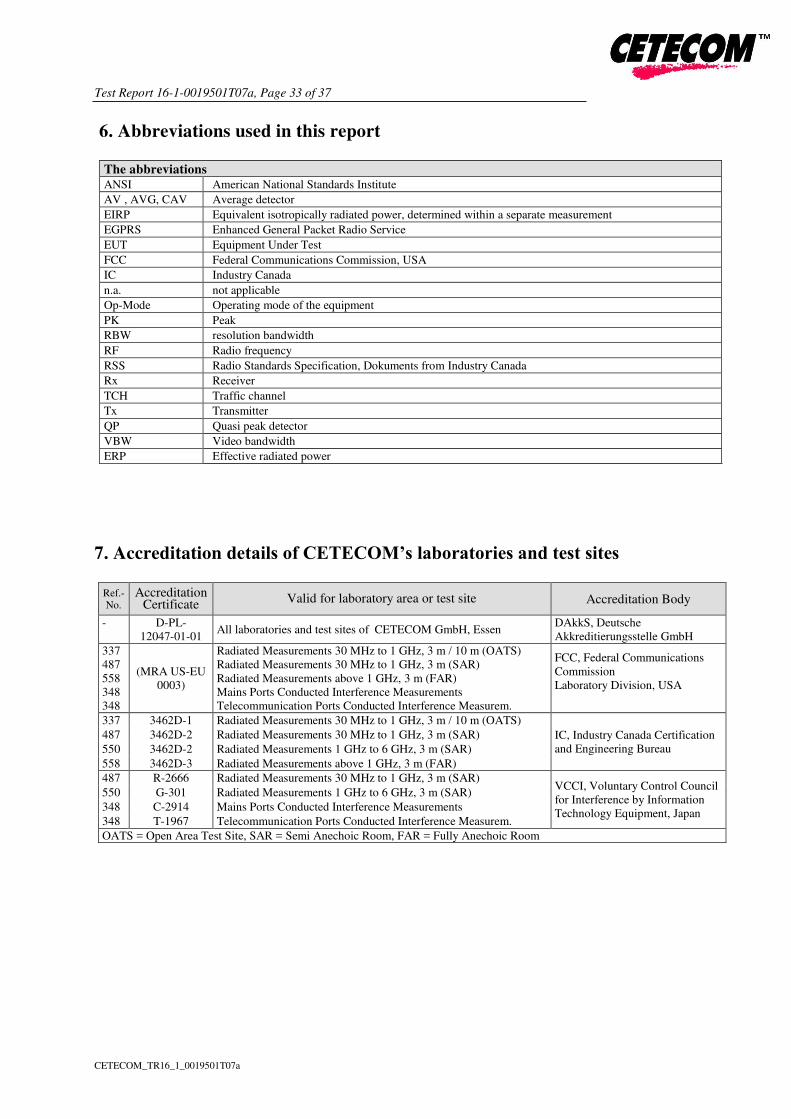
6. Abbreviations used in this report
The abbreviations ANSI American National Standards Institute
AV , AVG, CAV Average detector
EIRP Equivalent isotropically radiated power, determined within a separate measurement
EGPRS Enhanced General Packet Radio Service
EUT Equipment Under Test
FCC Federal Communications Commission, USA
IC Industry Canada
n.a. not applicable
Op-Mode Operating mode of the equipment
PK Peak
RBW resolution bandwidth
RF Radio frequency
RSS Radio Standards Specification, Dokuments from Industry Canada
Rx Receiver
TCH Traffic channel
Tx Transmitter
QP Quasi peak detector
VBW Video bandwidth
ERP Effective radiated power
7. Accreditation details of CETECOM’s laboratories and test sites
Ref.-No.
Accreditation Certificate
Valid for laboratory area or test site Accreditation Body
- D-PL-
12047-01-01 All laboratories and test sites of CETECOM GmbH, Essen
DAkkS, Deutsche
Akkreditierungsstelle GmbH
337
487
558
348
348
(MRA US-EU
0003)
Radiated Measurements 30 MHz to 1 GHz, 3 m / 10 m (OATS)
Radiated Measurements 30 MHz to 1 GHz, 3 m (SAR)
Radiated Measurements above 1 GHz, 3 m (FAR)
Mains Ports Conducted Interference Measurements
Telecommunication Ports Conducted Interference Measurem.
FCC, Federal Communications
Commission
Laboratory Division, USA
337 3462D-1 Radiated Measurements 30 MHz to 1 GHz, 3 m / 10 m (OATS)
IC, Industry Canada Certification
and Engineering Bureau
487 3462D-2 Radiated Measurements 30 MHz to 1 GHz, 3 m (SAR)
550 3462D-2 Radiated Measurements 1 GHz to 6 GHz, 3 m (SAR)
558 3462D-3 Radiated Measurements above 1 GHz, 3 m (FAR)
487 R-2666 Radiated Measurements 30 MHz to 1 GHz, 3 m (SAR) VCCI, Voluntary Control Council
for Interference by Information
Technology Equipment, Japan
550 G-301 Radiated Measurements 1 GHz to 6 GHz, 3 m (SAR)
348 C-2914 Mains Ports Conducted Interference Measurements
348 T-1967 Telecommunication Ports Conducted Interference Measurem.
OATS = Open Area Test Site, SAR = Semi Anechoic Room, FAR = Fully Anechoic Room

Test Report 16-1-0019501T07a, Page 34 of 37
CETECOM_TR16_1_0019501T07a
8. Instruments and Ancillary
8.1. Used equiment “CTC”
The “Ref.-No” in the left column of the following tables allows the clear identification of the laboratory equipment.
8.1.1. Test software and firmware of equipment
Ref
.-N
o.
Equipment Type Serial-No. Version of Firmware or Software during the test
001 EMI Test Receiver ESS 825132/017 Firm.= 1.21 , OTP=2.0, GRA=2.0 012 Signal Generator (EMS-cond.) SMY 01 839069/027 Firm.= V 2.02 013 Power Meter (EMS cond.) NRVD 839111/003 Firm.= V 1.51 017 Digital Radiocommunication Tester CMD 60 M 844365/014 Firmware = V 3.52 .22.01.99, DECT = D2.87 13.01.99 053 Audio Analyzer UPA3 860612/022 Firm. V 4.3 119 RT Harmonics Analyzer dig. Flickermeter B10 G60547 Firm.= V 3.1DHG 140 Signal Generator SMHU 831314/006 Firm.= 3.21 261 Thermal Power Sensor NRV-Z55 825083/0008 EPROM-Datum 02.12.04, SE EE 1 B 262 Power Meter NRV-S 825770/0010 Firm.= 2.6 263 Signal Generator SMP 04 826190/0007 Firm.=3.21
295 Racal Digital Radio Test Set 6103 1572 UNIT Firmware= 4.04, SW-Main=4.04, SW-BBP=1.04,
SW-DSP=1.02, Hardboot=1.02, Softboot=2.02
298 Univ. Radio Communication Tester CMU 200 832221/091 R&S Test Firmware =3.53 /3.54 (current Testsoftw. f.
all band used 323 Digital Radiocommunication Tester CMD 55 825878/0034 Firm.= 3.52 .22.01.99 335 CTC-EMS-Conducted System EMS Conducted - EMC 32 V 8.52 340 Digital Radiocommunication Tester CMD 55 849709/037 Firm.= 3.52 .22.01.99 355 Power Meter URV 5 891310/027 Firm.= 1.31 365 10V Insertion Unit 50 Ohm URV5-Z2 100880 Eprom Data = 31.03.08 366 Ultra Compact Simulator UCS 500 M4 V0531100594 Firm. UCS 500=001925/3.06a02, rc=ISMIEC 4.10 371 Bluetooth Tester CBT32 100153 CBT V5,30+ SW-Option K55, K57 377 EMI Test Receiver ESCS 30 100160 Firm.= 2.30, OTP= 02.01, GRA= 02.36 378 Broadband RF Field Monitor RadiSense III 03D00013SNO-08 Firm.= V.03D13 389 Digital Multimeter Keithley 2000 0583926 Firm. = A13 (Mainboard) A02 (Display)
392 Radio Communication Tester MT8820A 6K00000788
Firm.= 4.50 #005, IPL=4.01#001,OS=4.02#001,
GSM=4.41#013, W-CDMA= 4.54#004, scenario=
4.52#002
436 Univ. Radio Communication Tester CMU 200 103083 R&S Test Firmware Base=5.14, Mess-Software=
GSM:5.14 WCDMA:5.14 (current Testsoftw. F. all band 441 CTC-SAR-EMI Cable Loss System EMI field (SAR) - EMC 32 Version 8.52 442 CTC-SAR-EMS System EMS field (SAR) - EMC 32 Version 8.40
443 CTC-FAR-EMI-RSE System CTC-FAR-EMI-
RSE - Spuri 7.2.5 or EMC 32 Ver. 9.15.00
444 CTC-FAR-EMS field System-EMS-Field (FAR) - EMC 32 Version 9.15.00
460 Univ. Radio Communication Tester CMU 200 108901 R&S Test Firmware Base=5.14, GSM=5.14
WCDMA=5.14 (current Testsoftw.,f. all band to be used, 489 EMI Test Receiver ESU40 1000-30 Firmware=4.43 SP3, Bios=V5.1-16-3, Spec. =01.00 491 ESD Simulator dito ESD dito dito307022 V 2.30 524 Voltage Drop Simulator VDS 200 0196-16 Software Nr: 000037 Version V4.20a01 526 Burst Generator EFT 200 A 0496-06 Software Nr. 000034 Version V2.32 527 Micro Pulse Generator MPG 200 B 0496-05 Software-Nr. 000030 Version V2.43 528 Load Dump Simulator LD 200B 0496-06 Software-Nr. 000031 Version V2.35a01
546 Univ. Radio Communication Tester CMU 200 106436 R&S Test Firmware Base=5.14, GSM=5.14
WCDMA=5.14 (current Testsoftw.,f. all band to be used
547 Univ. Radio Communication Tester CMU 200 835390/014 R&S Test Firmware Base=V5.1403 (current Testsoftw.,
f. all band used, GSM = 5.14 WCDMA: = 5.14 584 Spectrum Analyzer FSU 8 100248 2.82_SP3
597 Univ. Radio Communication Tester CMU 200 100347 R&S Test Firmware Base=5.01, GSM=5.02 WCDMA=
not installed, Mainboard= µP1=V.850 598 Spectrum Analyzer FSEM 30 (Reserve) 831259/013 Firmware Bios 3.40 , Analyzer 3.40 Sp 2 620 EMI Test Receiver ESU 26 100362 4.43_SP3 642 Wideband Radio Communication Tester CMW 500 126089 Setup V03.26, Test programm component V03.02.20 670 Univ. Radio Communication Tester CMU 200 106833 µP1 =V8.50, Firmware = V.20 689 Vector Signal Generator SMU200 100970 02.20.360.142
692 Bluetooth Tester CBT 32 100236 CBT V 5.40, FW: V.2.41 (FPGA Digital, V. 3.09 FPGA
RF)
Test Report 16-1-0019501T07a, Page 35 of 37
CETECOM_TR16_1_0019501T07a
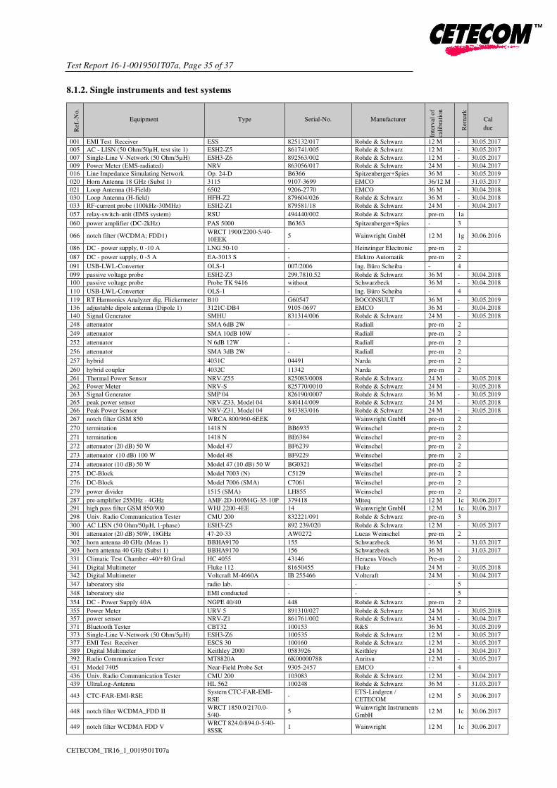
8.1.2. Single instruments and test systems
Ref
.-N
o.
Equipment Type Serial-No. Manufacturer
Inte
rval
of
cali
bra
tion
Rem
ark
Cal
due
001 EMI Test Receiver ESS 825132/017 Rohde & Schwarz 12 M - 30.05.2017 005 AC - LISN (50 Ohm/50µH, test site 1) ESH2-Z5 861741/005 Rohde & Schwarz 12 M - 30.05.2017 007 Single-Line V-Network (50 Ohm/5µH) ESH3-Z6 892563/002 Rohde & Schwarz 12 M - 30.05.2017 009 Power Meter (EMS-radiated) NRV 863056/017 Rohde & Schwarz 24 M - 30.04.2017 016 Line Impedance Simulating Network Op. 24-D B6366 Spitzenberger+Spies 36 M - 30.05.2019 020 Horn Antenna 18 GHz (Subst 1) 3115 9107-3699 EMCO 36/12 M - 31.03.2017 021 Loop Antenna (H-Field) 6502 9206-2770 EMCO 36 M - 30.04.2018 030 Loop Antenna (H-field) HFH-Z2 879604/026 Rohde & Schwarz 36 M - 30.04.2018 033 RF-current probe (100kHz-30MHz) ESH2-Z1 879581/18 Rohde & Schwarz 24 M - 30.04.2017
057 relay-switch-unit (EMS system) RSU 494440/002 Rohde & Schwarz pre-m 1a 060 power amplifier (DC-2kHz) PAS 5000 B6363 Spitzenberger+Spies - 3
066 notch filter (WCDMA; FDD1) WRCT 1900/2200-5/40-
10EEK 5 Wainwright GmbH 12 M 1g 30.06.2016
086 DC - power supply, 0 -10 A LNG 50-10 - Heinzinger Electronic pre-m 2 087 DC - power supply, 0 -5 A EA-3013 S - Elektro Automatik pre-m 2 091 USB-LWL-Converter OLS-1 007/2006 Ing. Büro Scheiba - 4 099 passive voltage probe ESH2-Z3 299.7810.52 Rohde & Schwarz 36 M - 30.04.2018 100 passive voltage probe Probe TK 9416 without Schwarzbeck 36 M - 30.04.2018
110 USB-LWL-Converter OLS-1 - Ing. Büro Scheiba - 4 119 RT Harmonics Analyzer dig. Flickermeter B10 G60547 BOCONSULT 36 M - 30.05.2019 136 adjustable dipole antenna (Dipole 1) 3121C-DB4 9105-0697 EMCO 36 M - 30.04.2018 140 Signal Generator SMHU 831314/006 Rohde & Schwarz 24 M - 30.05.2018
248 attenuator SMA 6dB 2W - Radiall pre-m 2 249 attenuator SMA 10dB 10W - Radiall pre-m 2 252 attenuator N 6dB 12W - Radiall pre-m 2 256 attenuator SMA 3dB 2W - Radiall pre-m 2 257 hybrid 4031C 04491 Narda pre-m 2 260 hybrid coupler 4032C 11342 Narda pre-m 2 261 Thermal Power Sensor NRV-Z55 825083/0008 Rohde & Schwarz 24 M - 30.05.2018 262 Power Meter NRV-S 825770/0010 Rohde & Schwarz 24 M - 30.05.2018 263 Signal Generator SMP 04 826190/0007 Rohde & Schwarz 36 M - 30.05.2019 265 peak power sensor NRV-Z33, Model 04 840414/009 Rohde & Schwarz 24 M - 30.05.2018 266 Peak Power Sensor NRV-Z31, Model 04 843383/016 Rohde & Schwarz 24 M - 30.05.2018
267 notch filter GSM 850 WRCA 800/960-6EEK 9 Wainwright GmbH pre-m 2 270 termination 1418 N BB6935 Weinschel pre-m 2 271 termination 1418 N BE6384 Weinschel pre-m 2 272 attenuator (20 dB) 50 W Model 47 BF6239 Weinschel pre-m 2 273 attenuator (10 dB) 100 W Model 48 BF9229 Weinschel pre-m 2 274 attenuator (10 dB) 50 W Model 47 (10 dB) 50 W BG0321 Weinschel pre-m 2 275 DC-Block Model 7003 (N) C5129 Weinschel pre-m 2 276 DC-Block Model 7006 (SMA) C7061 Weinschel pre-m 2 279 power divider 1515 (SMA) LH855 Weinschel pre-m 2 287 pre-amplifier 25MHz - 4GHz AMF-2D-100M4G-35-10P 379418 Miteq 12 M 1c 30.06.2017 291 high pass filter GSM 850/900 WHJ 2200-4EE 14 Wainwright GmbH 12 M 1c 30.06.2017
298 Univ. Radio Communication Tester CMU 200 832221/091 Rohde & Schwarz pre-m 3 300 AC LISN (50 Ohm/50µH, 1-phase) ESH3-Z5 892 239/020 Rohde & Schwarz 12 M - 30.05.2017
301 attenuator (20 dB) 50W, 18GHz 47-20-33 AW0272 Lucas Weinschel pre-m 2 302 horn antenna 40 GHz (Meas 1) BBHA9170 155 Schwarzbeck 36 M - 31.03.2017 303 horn antenna 40 GHz (Subst 1) BBHA9170 156 Schwarzbeck 36 M - 31.03.2017
331 Climatic Test Chamber -40/+80 Grad HC 4055 43146 Heraeus Vötsch Pre-m 2 341 Digital Multimeter Fluke 112 81650455 Fluke 24 M - 30.05.2018 342 Digital Multimeter Voltcraft M-4660A IB 255466 Voltcraft 24 M - 30.04.2017
347 laboratory site radio lab. - - - 5 348 laboratory site EMI conducted - - - 5 354 DC - Power Supply 40A NGPE 40/40 448 Rohde & Schwarz pre-m 2 355 Power Meter URV 5 891310/027 Rohde & Schwarz 24 M - 30.05.2018 357 power sensor NRV-Z1 861761/002 Rohde & Schwarz 24 M - 30.04.2017 371 Bluetooth Tester CBT32 100153 R&S 36 M - 30.05.2019 373 Single-Line V-Network (50 Ohm/5µH) ESH3-Z6 100535 Rohde & Schwarz 12 M - 30.05.2017 377 EMI Test Receiver ESCS 30 100160 Rohde & Schwarz 12 M - 30.05.2017 389 Digital Multimeter Keithley 2000 0583926 Keithley 24 M - 30.04.2017 392 Radio Communication Tester MT8820A 6K00000788 Anritsu 12 M - 30.05.2017
431 Model 7405 Near-Field Probe Set 9305-2457 EMCO - 4 436 Univ. Radio Communication Tester CMU 200 103083 Rohde & Schwarz 12 M - 30.04.2017 439 UltraLog-Antenna HL 562 100248 Rohde & Schwarz 36 M - 31.03.2017
443 CTC-FAR-EMI-RSE System CTC-FAR-EMI-
RSE -
ETS-Lindgren /
CETECOM 12 M 5 30.06.2017
448 notch filter WCDMA_FDD II WRCT 1850.0/2170.0-
5/40- 5
Wainwright Instruments
GmbH 12 M 1c 30.06.2017
449 notch filter WCDMA FDD V WRCT 824.0/894.0-5/40-
8SSK 1 Wainwright 12 M 1c 30.06.2017

Test Report 16-1-0019501T07a, Page 36 of 37
CETECOM_TR16_1_0019501T07a
Ref
.-N
o.
Equipment Type Serial-No. Manufacturer
Inte
rval
of
cali
bra
tion
Rem
ark
Cal
due
454 Oscilloscope HM 205-3 9210 P 29661 Hameg - 4 456 DC-Power supply 0-5 A EA 3013 S 207810 Elektro Automatik pre-m 2 459 DC -Power supply 0-5 A , 0-32 V EA-PS 2032-50 910722 Elektro Automatik pre-m 2 460 Univ. Radio Communication Tester CMU 200 108901 Rohde & Schwarz 12 M - 30.04.2017
463 Universal source HP3245A 2831A03472 Agilent - 4 466 Digital Multimeter Fluke 112 89210157 Fluke USA 24 M - 30.05.2018 467 Digital Multimeter Fluke 112 89680306 Fluke USA 36 M - 30.04.2018 468 Digital Multimeter Fluke 112 90090455 Fluke USA 36 M - 30.04.2018
477 ReRadiating GPS-System AS-47 - Automotive Cons. Fink - 3 480 power meter (Fula) NRVS 838392/031 Rohde & Schwarz 24 M - 30.04.2017
482 filter matrix Filter matrix SAR 1 - CETECOM (Brl) - 1d
484 pre-amplifier 2,5 - 18 GHz AMF-5D-02501800-25-
10P 1244554 Miteq 12 M - 30.06.2017
487 System CTC NSA-Verification SAR-EMI System EMI field (SAR)
NSA -
ETS Lindgren /
CETECOM 24 M - 31.07.2017
489 EMI Test Receiver ESU40 1000-30 Rohde & Schwarz 12 M - 30.05.2017
502 band reject filter WRCG 1709/1786-
1699/1796- SN 9 Wainwright pre-m 2
503 band reject filter WRCG 824/849-814/859- SN 5 Wainwright pre-m 2
512 notch filter GSM 850 WRCA 800/960-02/40-
6EEK SN 24 Wainwrght 12 M 1c 30.06.2017
517 relais switch matrix HF Relais Box Keithley SE 04 Keithley pre-m 2 523 Digital Multimeter L4411A MY46000154 Agilent 24 M - 30.04.2017
529 6 dB Broadband resistive power divider Model 1515 LH 855 Weinschel pre-m 2 530 10 dB Broadband resistive power divider R 416110000 LOT 9828 - pre-m 2 546 Univ. Radio Communication Tester CMU 200 106436 R&S 12 M - 30.05.2017 547 Univ. Radio Communication Tester CMU 200 835390/014 Rohde & Schwarz 12 M - 30.04.2017 549 Log.Per-Antenna HL025 1000060 Rohde & Schwarz 36/12 M - 31.07.2018
550 System CTC S-VSWR Verification SAR-
EMI System EMI Field SAR S-
VSWR -
ETS
Lindgren/CETECOM 24 M - 31.07.2017
552 high pass filter 2,8-18GHz WHKX 2.8/18G-10SS 4 Wainwright 12 M 1c 30.06.2017 557 System CTC-OTA-2 R&S TS8991 - Rohde & Schwarz 12 M 5 30.09.2016
558 System CTC FAR S-VSWR System CTC FAR S-
VSWR - CTC 24 M - 19.04.2017
574 Biconilog Hybrid Antenna BTA-L 980026L Frankonia 36/12 M - 31.03.2019
584 Spectrum Analyzer FSU 8 100248 Rohde & Schwarz pre-m - 594 Wideband Radio Communication Tester CMW 500 101757 Rohde & Schwarz 12 M - 30.04.2017
597 Univ. Radio Communication Tester CMU 200 100347 Rohde & Schwarz pre-m - 598 Spectrum Analyzer FSEM 30 (Reserve) 831259/013 Rohde & Schwarz 24 M - 30.04.2017 600 power meter NRVD (Reserve) 834501/018 Rohde & Schwarz 24 M - 30.04.2017 601 medium-sensitivity diode sensor NRV-Z5 (Reserve) 8435323/003 Rohde & Schwarz 24 M - 30.04.2017
602 peak power sensor NRV-Z32 (Reserve) 835080 Rohde & Schwarz 24 M - 611 DC power supply E3632A KR 75305854 Agilent pre-m 2 612 DC power supply E3632A MY 40001321 Agilent pre-m 2 613 Attenuator R416120000 20dB 10W Lot. 9828 Radiall pre-m 2 616 Digitalmultimeter Fluke 177 88900339 Fluke 24 M - 30.05.2018
617 Power Splitter/Combiner ZFSC-2-2-S+ S F987001108 Mini Circuits - 2 618 Power Splitter/Combiner 50PD-634 600994 JFW Industries USA - 2 619 Power Splitter/Combiner 50PD-634 600995 JFW Industries, USA - 3 620 EMI Test Receiver ESU 26 100362 Rohde-Schwarz 12 M - 30.05.2017
621 Step Attenuator 0-139 dB RSP 100017 Rohde & Schwarz pre-m 2 625 Generic Test Load USB Generic Test Load USB - CETECOM - 2
627 data logger OPUS 1 201.0999.9302.6.4.1.4
3 G. Lufft GmbH 24 M - 30.04.2017
634 Spectrum Analyzer FSM (HF-Unit) 826188/010 Rohde & Schwarz pre-m 2
637 High Speed HDMI with Ethernet 1m HDMI cable with Ethernet
1m - KogiLink - 2
638 HDMI Kabel with Ethernet 1,5 m flach HDMI cable with Ethernet - Reichelt - 2 640 HDMI cable 2m rund HDMI cable 2m rund - Reichelt - 2 641 HDMI cable with Ethernet Certified HDMI cable with - PureLink - 2 644 Amplifierer ZX60-2534M+ SN865701299 Mini-Circuits - - 670 Univ. Radio Communication Tester CMU 200 106833 Rohde & Schwarz 24 M - 30.05.2018
671 DC-power supply 0-5 A EA-3013S - Elektro Automatik pre-m 2 678 Power Meter NRP 101638 Rohde&Schwarz pre-m - 683 Spectrum Analyzer FSU 26 200571 Rohde & Schwarz 12 M - 30.05.2017
686 Field Analyzer EHP-200A 160WX30702 Narda Safety Test
Solutions 24 M - 30.04.2017
687 Signal Generator SMF 100A 102073 Rohde&Schwarz 12 M - 30.05.2017
688 Pre Amp JS-18004000-40-8P 1750117 Miteq pre-m - 690 Spectrum Analyzer FSU 100302/026 Rohde&Schwarz 12 M - 30.05.2017 692 Bluetooth Tester CBT 32 100236 Rohde & Schwarz 36 M - 31.03.2017
697 Power Splitter ZN4PD-642W-S+ 165001445 Mini-Circuits - 2

Test Report 16-1-0019501T07a, Page 37 of 37
CETECOM_TR16_1_0019501T07a
8.1.3. Legend
Note / remarks Calibrated during system calibration:
1a System CTC-SAR-EMS (Ref.-No. 442)
1b System-CTC-EMS-Conducted (Ref.-No. 335)
1c System CTC-FAR-EMI-RSE (Ref.-No . 443)
1d System CTC-SAR-EMI (Ref.-No . 441)
1e System CTC-OATS (EMI radiated) (Ref.-No. 337)
1 f System CTC-CTIA-OTA (Ref.-No . 420)
1 g System CTC-FAR-EMS (Ref.-No . 444)
2 Calibration or equipment check immediately before measurement
3 Regulatory maintained equipment for functional check or support purpose
calibration of this equipment has no effect on measuring result 4 Ancillary equipment without calibration e.g. mechanical equipment or monitoring equipment
5 Test System
Interval of calibration 12 M 12 month
24 M 24 month
36 M 36 month
24/12 M Calibration every 24 months, between this every 12 months internal validation
36/12 M Calibration every 36 months, between this every 12 months internal validation
Pre-m Check before starting the measurement
- Without calibration
9. Versions of test reports (change history)
Version Applied changes Date of release
-- Initial release 2016-06-28
-- -- --