t e c h n i c a l r e f e r e n c e m a n u a l anki vector
TRANSCRIPT

T E C H N I C A L R E F E R E N C E M A N U A L
Anki Vector
A LOVE LETTER TO THE
LITTLE DUDE
A U T H O R R A N D A L L M A A S
O V E R V I E W This book explores how the Anki Vector was realized in hardware and software.
drawing by Steph Dere
Copyright © 2019-2021 Randall Maas. All rights reserved.

A N K I V E C T O R · 2 0 2 1 . 0 2 . 1 4 ii
RANDALL MAAS has spent decades in Washington and Minnesota. He consults in embedded
systems development, especially medical devices. Before that he did a lot of other things…
like everyone else in the software industry. He is also interested in geophysical models,
formal semantics, model theory and compilers.
You can contact him at [email protected].
LinkedIn: http://www.linkedin.com/pub/randall-maas/9/838/8b1

A N K I V E C T O R · 2 0 2 1 . 0 2 . 1 4 iii
Table of Contents
ANKI VECTOR ..................................................................................................................... I
A LOVE LETTER TO THE LITTLE DUDE ................................................................................... I
PREFACE ............................................................................................................................1 1. ORGANIZATION OF THIS DOCUMENT ..............................................................................1 1.1. ORDER OF DEVELOPMENT ...........................................................................................3 1.2. VERSION(S) .............................................................................................................4 1.3. CUSTOMIZATION AND PATCHING ..................................................................................4 1.4. CODE NAMES OR VECTOR VS VICTOR .............................................................................4
CHAPTER 1 .........................................................................................................................6
OVERVIEW OF VECTOR .......................................................................................................6 2. OVERVIEW ..............................................................................................................6 2.1. COMPELLING CHARACTER ...........................................................................................6 2.2. FEATURES ...............................................................................................................7 3. PRIVACY AND SECURITY ..............................................................................................9 4. COZMO ..................................................................................................................9 5. ALEXA INTEGRATION ................................................................................................ 10
PART I .............................................................................................................................. 11
ELECTRONICS DESIGN ....................................................................................................... 11
CHAPTER 2 ....................................................................................................................... 13
ELECTRONICS DESIGN DESCRIPTION ................................................................................. 13 6. DESIGN OVERVIEW .................................................................................................. 13 6.1. POWER SOURCE AND DISTRIBUTION TREE ..................................................................... 16 6.2. MANUFACTURING TEST SUPPORT ............................................................................... 17 7. REFERENCES & RESOURCES ....................................................................................... 17
CHAPTER 3 ....................................................................................................................... 18
HEAD-BOARD ELECTRONICS DESIGN DESCRIPTION ............................................................ 18 8. THE HEAD-BOARD (THE MAIN PROCESSOR BOARD) ......................................................... 18 8.1. THE APQ8009 PROCESSOR ...................................................................................... 19 8.2. SPEAKER ............................................................................................................... 19 8.3. CAMERA ............................................................................................................... 20 8.4. THE LCD ............................................................................................................... 20 8.5. POWER MANAGEMENT ............................................................................................. 20 8.6. TRIM, CALIBRATION SERIAL NUMBERS AND KEYS ............................................................ 20 8.7. MANUFACTURING TEST CONNECTOR/INTERFACE ............................................................ 21 9. REFERENCES & RESOURCES ....................................................................................... 21
CHAPTER 4 ....................................................................................................................... 22
BACKPACK & BODY-BOARD ELECTRONICS DESIGN DESCRIPTION ....................................... 22 10. THE BACKPACK BOARD ............................................................................................. 22

A N K I V E C T O R · 2 0 2 1 . 0 2 . 1 4 iv
10.1. BACKPACK CONNECTION ........................................................................................... 23 10.2. ELECTRO-STATIC DISCHARGE (ESD) PROTECTION ........................................................... 23 10.3. OPERATION ........................................................................................................... 23 11. THE BODY-BOARD .................................................................................................. 25 11.1. POWER MANAGEMENT ............................................................................................. 26 11.2. ELECTRO-STATIC DISCHARGE (ESD) PROTECTION ........................................................... 29 11.3. STM32F030 MICROCONTROLLER ............................................................................... 29 11.4. SENSING ............................................................................................................... 31 11.5. OUTPUTS .............................................................................................................. 33 11.6. COMMUNICATION ................................................................................................... 34 11.7. COMMUNICATION WITH THE HEAD-BOARD ................................................................... 34 12. REFERENCES & RESOURCES ....................................................................................... 35
CHAPTER 5 ....................................................................................................................... 37
ACCESSORY ELECTRONICS DESIGN DESCRIPTION ............................................................... 37 13. CHARGING STATION ................................................................................................. 37 14. HABITAT (VECTOR SPACE) ......................................................................................... 38 15. CUBE ................................................................................................................... 38 15.1. OVER THE AIR APPLICATION FIRMWARE DOWNLOAD ...................................................... 39 15.2. REFERENCES & RESOURCES ....................................................................................... 39
PART II ............................................................................................................................. 41
BASIC OPERATION ........................................................................................................... 41
CHAPTER 6 ....................................................................................................................... 43
ARCHITECTURE ................................................................................................................ 43 16. OVERVIEW OF VECTOR’S COMMUNICATION INFRASTRUCTURE ............................................ 43 16.1. APPLICATION SERVICES ARCHITECTURE ......................................................................... 44 16.2. EMOTION MODEL, BEHAVIOUR ENGINE, ACTIONS AND ANIMATION ENGINE ......................... 46 17. STORAGE SYSTEM ................................................................................................... 47 17.1. ELECTRONIC MEDICAL RECORD (EMR)......................................................................... 47 17.2. OEM PARTITION FOR OWNER CERTIFICATES AND LOGS .................................................... 49 18. SECURITY AND PRIVACY ............................................................................................ 49 18.1. ENCRYPTED COMMUNICATION ................................................................................... 50 18.2. ENCRYPTED FILESYSTEM ............................................................................................ 50 18.3. THE OPERATING SYSTEM .......................................................................................... 50 18.4. AUTHENTICATION ................................................................................................... 51 19. CONFIGURATION AND ASSET FILES............................................................................... 51 19.1. CONFIGURATION FILES .............................................................................................. 51 20. SOFTWARE-HARDWARE LAYERS ................................................................................. 52 20.1. THE BODY BOARD INPUT/OUTPUT .............................................................................. 52 20.2. THE LCD DISPLAY .................................................................................................... 52 20.3. THE CAMERA.......................................................................................................... 53 21. REFERENCES & RESOURCES ....................................................................................... 53
CHAPTER 7 ....................................................................................................................... 55
STARTUP ......................................................................................................................... 55

A N K I V E C T O R · 2 0 2 1 . 0 2 . 1 4 v
22. STARTUP ............................................................................................................... 55 22.1. QUALCOMM’S PRIMARY AND SECONDARY BOOT-LOADER ................................................. 55 22.2. ANDROID BOOT-LOADER (ABOOT) ............................................................................ 56 22.3. RECOVERY BOOT .................................................................................................... 57 22.4. REGULAR SYSTEM BOOT ............................................................................................ 57 22.5. ABNORMAL SYSTEM BOOT......................................................................................... 60 22.6. REGULAR REBOOTS ................................................................................................. 60 23. REFERENCES & RESOURCES ....................................................................................... 60
CHAPTER 8 ....................................................................................................................... 61
POWER MANAGEMENT .................................................................................................... 61 24. POWER MANAGEMENT ............................................................................................. 61 24.1. BATTERY MANAGEMENT ........................................................................................... 61 24.2. RESPONSES, SHEDDING LOAD / POWER SAVING EFFORTS .................................................. 62 24.3. SLEEP STATES ......................................................................................................... 64 24.4. ACTIVITY LEVEL MANAGEMENT .................................................................................. 65 24.5. SHUTDOWN ........................................................................................................... 65 24.6. THE CUBE POWER MANAGEMENT .............................................................................. 66 25. CHARGING ............................................................................................................ 66
CHAPTER 9 ....................................................................................................................... 67
BASIC INPUTS AND OUTPUTS ........................................................................................... 67 26. BUTTON, TOUCH AND CLIFF SENSOR INPUT ................................................................... 67 26.1. TOUCH SENSING INFORMATION .................................................................................. 68 26.2. TIME OF FLIGHT PROXIMITY SENSOR ............................................................................ 68 27. BACKPACK LIGHTS CONTROL ...................................................................................... 68
CHAPTER 10 ..................................................................................................................... 70
INERTIAL MOTION SENSING ............................................................................................. 70 28. MOTION SENSING ................................................................................................... 70 28.1. ACCELEROMETER AND GYROSCOPE .............................................................................. 70 28.2. TILTED HEAD ......................................................................................................... 71 28.3. SENSING MOTION ................................................................................................... 71 28.4. SENSING INTERACTIONS ............................................................................................ 71 29. REFERENCES AND RESOURCES .................................................................................... 72
PART III ............................................................................................................................ 73
COMMUNICATION ........................................................................................................... 73
CHAPTER 11 ..................................................................................................................... 75
COMMUNICATION ........................................................................................................... 75 30. OVERVIEW OF VECTOR’S COMMUNICATION INFRASTRUCTURE ............................................ 75 31. INTERNAL COMMUNICATION WITH PERIPHERALS ............................................................. 76 31.1. COMMUNICATION WITH THE BODY-BOARD ................................................................... 76 31.2. SERIAL BOOT CONSOLE ............................................................................................. 76 31.3. USB .................................................................................................................... 76 32. BLUETOOTH LE ....................................................................................................... 76

A N K I V E C T O R · 2 0 2 1 . 0 2 . 1 4 vi
33. WIFI .................................................................................................................... 78 33.1. FIREWALL .............................................................................................................. 79 33.2. WIFI CONFIGURATION .............................................................................................. 79 33.3. ACCESS POINT MODE .............................................................................................. 80 34. NETWORK COMMUNICATION ..................................................................................... 80 34.1. COMMUNICATING WITH MOBILE APP AND SDK ............................................................. 80 34.2. WEB-VIZ, A VISUAL CHARACTERIZATION TOOL............................................................... 82 35. CLOUD SERVERS ...................................................................................................... 83 35.1. ROBOT CERTIFICATE ................................................................................................ 84 36. REFERENCES & RESOURCES ....................................................................................... 84
CHAPTER 12 ..................................................................................................................... 85
BODY-BOARD COMMUNICATION PROTOCOL.................................................................... 85 37. COMMUNICATION PROTOCOL OVERVIEW ...................................................................... 85 37.1. BASIC STRUCTURES.................................................................................................. 86 37.2. THE MESSAGE FRAMES ............................................................................................ 86 37.3. ACKNOWLEDGEMENT AND NEGATIVE ACKNOWLEDGEMENT OF MESSAGES ........................... 87 37.4. UPDATING THE FIRMWARE APPLICATION ....................................................................... 87 37.5. COMMAND-LINE INTERFACE ...................................................................................... 88 38. MESSAGE FORMATS ................................................................................................. 89 38.1. ENUMERATIONS ..................................................................................................... 90 38.2. STRUCTURES .......................................................................................................... 91 38.3. DATA FRAME FROM BODY BOARD ............................................................................... 91 38.4. DATA FRAME FROM HEAD BOARD TO BODY BOARD ........................................................ 93
CHAPTER 13 ..................................................................................................................... 94
VECTOR BLUETOOTH LE COMMUNICATION PROTOCOL ..................................................... 94 39. COMMUNICATION PROTOCOL OVERVIEW ...................................................................... 94 39.1. SETTING UP THE COMMUNICATION CHANNEL ................................................................. 96 39.2. FRAGMENTATION AND REASSEMBLY ............................................................................ 97 39.3. ENCRYPTION SUPPORT ............................................................................................. 98 39.4. THE RTS LAYER ...................................................................................................... 99 39.5. FETCHING A LOG ................................................................................................... 100 39.6. A BLE SHELL CONNECTION ...................................................................................... 101 40. MESSAGE FORMATS ............................................................................................... 102 40.1. APPLICATION CONNECTION ID .................................................................................. 103 40.2. BLE SHELL CONNECT.............................................................................................. 104 40.3. BLE SHELL DISCONNECT ......................................................................................... 104 40.4. BLE SHELL TO CLIENT ............................................................................................. 104 40.5. BLE SHELL TO SERVER ............................................................................................ 105 40.6. CANCEL PAIRING ................................................................................................... 106 40.7. CHALLENGE ......................................................................................................... 107 40.8. CHALLENGE SUCCESS .............................................................................................. 108 40.9. CLOUD SESSION .................................................................................................... 109 40.10. CONNECT ............................................................................................................ 110 40.11. DISCONNECT ........................................................................................................ 111 40.12. FILE DOWNLOAD .................................................................................................. 112 40.13. LOG ................................................................................................................... 113

A N K I V E C T O R · 2 0 2 1 . 0 2 . 1 4 vii
40.14. NONCE ............................................................................................................... 114 40.15. OTA UPDATE....................................................................................................... 115 40.16. RESPONSE ........................................................................................................... 116 40.17. SDK PROXY ......................................................................................................... 117 40.18. SSH ................................................................................................................... 118 40.19. STATUS .............................................................................................................. 119 40.20. VERSIONS LIST ..................................................................................................... 120 40.21. WIFI ACCESS POINT ............................................................................................... 121 40.22. WIFI CONNECT ..................................................................................................... 122 40.23. WIFI FORGET ....................................................................................................... 123 40.24. WIFI IP ADDRESS .................................................................................................. 124 40.25. WIFI SCAN .......................................................................................................... 125
CHAPTER 14 ................................................................................................................... 126
CUBE BLUETOOTH LE COMMUNICATION PROTOCOL ....................................................... 126 41. CUBE COMMUNICATION PROTOCOL OVERVIEW ............................................................ 126 41.1. SENDING THE FIRMWARE APPLICATION ....................................................................... 126 41.2. RETRIEVING AND STREAMING ACCELEROMETER DATA .................................................... 127 42. CHARACTERISTIC MESSAGE FORMATS ........................................................................ 128 42.1. STRUCTURES ........................................................................................................ 128 42.2. LED CONTROL ...................................................................................................... 128 42.3. APPLICATION VERSION ........................................................................................... 129 42.4. BATTERY AND ACCELEROMETER CHARACTERISTIC .......................................................... 129 42.5. OTA DOWNLOAD .................................................................................................. 129 42.6. REFERENCES & RESOURCES ..................................................................................... 129
CHAPTER 15 ................................................................................................................... 130
THE HTTPS BASED API .................................................................................................... 130 43. OVERVIEW OF THE SDK HTTPS API .......................................................................... 130 43.1. SDK MESSAGE GROUPINGS..................................................................................... 130 44. COMMON ELEMENTS ............................................................................................. 132 44.1. ENUMERATIONS ................................................................................................... 132 44.2. STRUCTURES ........................................................................................................ 134 45. ACCESSORIES AND CUSTOM OBJECTS ......................................................................... 136 45.1. ENUMERATIONS ................................................................................................... 136 45.2. EVENTS .............................................................................................................. 140 45.3. CREATE FIXED CUSTOM OBJECT ................................................................................ 143 45.4. DEFINE CUSTOM OBJECT ........................................................................................ 144 45.5. DELETE CUSTOM OBJECTS ....................................................................................... 147 46. ACTIONS AND BEHAVIOUR ...................................................................................... 148 46.1. ENUMERATIONS ................................................................................................... 148 46.2. EVENTS .............................................................................................................. 149 46.3. STRUCTURES ........................................................................................................ 150 46.4. BEHAVIOR CONTROL AND ASSUME BEHAVIOR CONTROL ................................................ 153 46.5. CANCEL ACTION BY ID TAG ..................................................................................... 155 46.6. CANCEL BEHAVIOR ................................................................................................ 155 46.7. LOOK AROUND IN PLACE ........................................................................................ 156 47. ALEXA ................................................................................................................ 157

A N K I V E C T O R · 2 0 2 1 . 0 2 . 1 4 viii
47.1. ENUMERATIONS ................................................................................................... 157 47.2. EVENTS .............................................................................................................. 157 47.3. ALEXA AUTHORIZATION STATE ................................................................................. 158 47.4. ALEXA OPT IN ...................................................................................................... 158 48. ANIMATION ......................................................................................................... 159 48.1. STRUCTURES ........................................................................................................ 159 48.2. LIST ANIMATIONS ................................................................................................. 159 48.3. LIST ANIMATION TRIGGERS ..................................................................................... 160 48.4. PLAY ANIMATION ................................................................................................. 160 48.5. PLAY ANIMATION TRIGGER ..................................................................................... 161 49. ATTENTION TRANSFER............................................................................................ 162 49.1. EVENTS .............................................................................................................. 162 49.2. GET LATEST ATTENTION TRANSFER ............................................................................ 163 50. AUDIO ............................................................................................................... 164 50.1. ENUMERATIONS ................................................................................................... 164 50.2. EVENTS .............................................................................................................. 165 50.3. APP INTENT ......................................................................................................... 167 50.4. AUDIO FEED (FROM THE MICROPHONES) .................................................................... 168 50.5. AUDIO PROCESSING MODE ..................................................................................... 169 50.6. EXTERNAL AUDIO STREAM PLAYBACK ........................................................................ 170 50.7. MASTER VOLUME ................................................................................................. 172 50.8. SAY TEXT ............................................................................................................ 173 51. BATTERY ............................................................................................................. 174 51.1. ENUMERATIONS ................................................................................................... 174 51.2. BATTERY STATE .................................................................................................... 174 52. CONNECTION ....................................................................................................... 175 52.1. EVENTS .............................................................................................................. 175 52.2. EVENT STREAM .................................................................................................... 177 52.3. PROTOCOL VERSION .............................................................................................. 178 52.4. SDK INITIALIZATION .............................................................................................. 179 52.5. USER AUTHENTICATION .......................................................................................... 180 52.6. VERSION STATE .................................................................................................... 181 53. CUBE ................................................................................................................. 182 53.1. ENUMERATIONS ................................................................................................... 182 53.2. EVENTS .............................................................................................................. 183 53.3. CONNECT CUBE .................................................................................................... 184 53.4. CUBES AVAILABLE ................................................................................................. 184 53.5. DISCONNECT CUBE ................................................................................................ 185 53.6. DOCK WITH CUBE ................................................................................................. 186 53.7. FLASH CUBE LIGHTS ............................................................................................... 187 53.8. FORGET PREFERRED CUBE ....................................................................................... 187 53.9. PICKUP OBJECT .................................................................................................... 188 53.10. PLACE OBJECT ON GROUND HERE ............................................................................. 189 53.11. POP A WHEELIE.................................................................................................... 190 53.12. ROLL BLOCK ........................................................................................................ 191 53.13. ROLL OBJECT ....................................................................................................... 192 53.14. SET CUBE LIGHTS .................................................................................................. 193 53.15. SET PREFERRED CUBE ............................................................................................. 194
A N K I V E C T O R · 2 0 2 1 . 0 2 . 1 4 ix
54. DIAGNOSTICS ....................................................................................................... 195 54.1. CHECK CLOUD CONNECTION .................................................................................... 195 54.2. UPLOAD DEBUG LOGS ............................................................................................ 196 55. DISPLAY .............................................................................................................. 197 55.1. EVENTS .............................................................................................................. 197 55.2. DISPLAY IMAGE RGB ............................................................................................. 197 55.3. ENABLE MIRROR MODE ......................................................................................... 198 55.4. SET EYE COLOR ..................................................................................................... 198 56. FACES ................................................................................................................ 199 56.1. ENUMERATIONS ................................................................................................... 199 56.2. EVENTS .............................................................................................................. 200 56.3. CANCEL FACE ENROLLMENT ..................................................................................... 202 56.4. ENABLE FACE DETECTION ........................................................................................ 203 56.5. ENROLL FACE ....................................................................................................... 204 56.6. ERASE ALL ENROLLED FACES .................................................................................... 204 56.7. ERASE ENROLLED FACE BY ID ................................................................................... 205 56.8. FIND FACES ......................................................................................................... 205 56.9. REQUEST ENROLLED NAMES .................................................................................... 206 56.10. SET FACE TO ENROLL .............................................................................................. 207 56.11. UPDATE ENROLLED FACE BY ID ................................................................................. 208 57. FEATURES & ENTITLEMENTS .................................................................................... 209 57.1. ENUMERATIONS ................................................................................................... 209 57.2. GET FEATURE FLAG ............................................................................................... 210 57.3. GET FEATURE FLAG LIST .......................................................................................... 211 57.4. UPDATE USER ENTITLEMENTS .................................................................................. 212 58. IMAGE PROCESSING ............................................................................................... 213 58.1. ENUMERATIONS ................................................................................................... 213 58.2. EVENTS .............................................................................................................. 213 58.3. CAMERA FEED ...................................................................................................... 215 58.4. CAPTURE SINGLE IMAGE ......................................................................................... 216 58.5. ENABLE IMAGE STREAMING ..................................................................................... 217 58.6. ENABLE MARKER DETECTION ................................................................................... 218 58.7. ENABLE MOTION DETECTION ................................................................................... 219 58.8. GET CAMERA CONFIG ............................................................................................ 220 58.9. IS IMAGE STREAMING ENABLED ................................................................................ 220 58.10. SET CAMERA SETTINGS ........................................................................................... 221 59. INTERACTIONS WITH OBJECTS .................................................................................. 222 59.1. STRUCTURES ........................................................................................................ 222 59.2. DRIVE OFF CHARGER .............................................................................................. 223 59.3. DRIVE ON CHARGER ............................................................................................... 223 59.4. GO TO OBJECT ..................................................................................................... 224 59.5. TURN TOWARDS FACE ............................................................................................ 225 60. JDOCS ................................................................................................................ 226 60.1. ENUMERATIONS ................................................................................................... 226 60.2. STRUCTURES ........................................................................................................ 226 60.3. EVENTS .............................................................................................................. 227 60.4. PULL JDOCS ......................................................................................................... 227 61. MAPPING ........................................................................................................... 228

A N K I V E C T O R · 2 0 2 1 . 0 2 . 1 4 x
61.1. THE NAVIGATION MAP FEED..................................................................................... 228 62. MOTION CONTROL ................................................................................................ 230 62.1. DRIVE STRAIGHT ................................................................................................... 230 62.2. DRIVE WHEELS ..................................................................................................... 231 62.3. GO TO POSE ........................................................................................................ 232 62.4. MOVE HEAD ........................................................................................................ 233 62.5. MOVE LIFT .......................................................................................................... 233 62.6. SET HEAD ANGLE .................................................................................................. 234 62.7. SET LIFT HEIGHT ................................................................................................... 235 62.8. STOP ALL MOTORS ................................................................................................ 236 62.9. TURN IN PLACE..................................................................................................... 237 63. MOTION SENSING AND ROBOT STATE ........................................................................ 238 63.1. ENUMERATIONS ................................................................................................... 238 63.2. STRUCTURES ........................................................................................................ 238 63.3. EVENTS .............................................................................................................. 240 64. ON BOARDING ..................................................................................................... 242 64.1. ENUMERATIONS ................................................................................................... 242 64.2. EVENTS .............................................................................................................. 243 64.3. ONBOARDING COMPLETE REQUEST ........................................................................... 244 64.4. ONBOARDING INPUT ............................................................................................. 244 64.5. ONBOARDING STATE ............................................................................................. 247 64.6. ONBOARDING WAKE UP REQUEST ............................................................................ 247 64.7. ONBOARDING WAKE UP STARTED REQUEST ................................................................ 247 65. PHOTOS .............................................................................................................. 248 65.1. STRUCTURES ........................................................................................................ 248 65.2. EVENTS .............................................................................................................. 248 65.3. DELETE PHOTO ..................................................................................................... 249 65.4. PHOTO ............................................................................................................... 249 65.5. PHOTOS INFO....................................................................................................... 250 65.6. THUMBNAIL......................................................................................................... 251 66. SETTINGS AND PREFERENCES.................................................................................... 252 66.1. STRUCTURES ........................................................................................................ 252 66.2. UPDATE SETTINGS ................................................................................................. 252 66.3. UPDATE ACCOUNT SETTINGS ................................................................................... 253 67. SOFTWARE UPDATES ............................................................................................. 254 67.1. ENUMERATIONS ................................................................................................... 254 67.2. START UPDATE ENGINE .......................................................................................... 254 67.3. CHECK UPDATE STATUS .......................................................................................... 254 67.4. UPDATE AND RESTART ........................................................................................... 255 68. HISTORICAL ODDITIES ............................................................................................. 255
CHAPTER 16 ................................................................................................................... 256
THE WEB VISUALIZATION PROTOCOL ............................................................................. 256 69. COMMUNICATION OVERVIEW .................................................................................. 256 69.1. CONSOLE VARIABLES ............................................................................................. 257 70. WEBSOCKET OVERVIEW ......................................................................................... 257 70.1. SETTING UP THE COMMUNICATION CHANNEL ............................................................... 259 70.2. RECEIVED EVENTS ................................................................................................. 260

A N K I V E C T O R · 2 0 2 1 . 0 2 . 1 4 xi
70.3. POSTED EVENTS.................................................................................................... 275
CHAPTER 17 ................................................................................................................... 278
THE CLOUD SERVICES ..................................................................................................... 278 71. CONFIGURATION ................................................................................................... 278 72. JDOCS SERVER ..................................................................................................... 279 72.1. JDOCS INTERACTION .............................................................................................. 279 72.2. DELETE DOCUMENT ............................................................................................... 280 72.3. ECHO TEST........................................................................................................... 280 72.4. READ DOCUMENTS ................................................................................................ 281 72.5. READ DOCUMENT ITEM .......................................................................................... 281 72.6. WRITE DOCUMENT ................................................................................................ 282 72.7. OTHER AREAS ...................................................................................................... 282 73. NATURAL LANGUAGE PROCESSING ............................................................................ 283 73.2. PARAMETERS FOR THE CLOUD INTENTS ...................................................................... 283 74. LOGS AND TRACE DATA ........................................................................................... 285 74.1. LOG UPLOADER .................................................................................................... 285 74.2. CRASH UPLOADER ................................................................................................. 286 74.3. DAS MANAGER.................................................................................................... 287 75. REFERENCES AND RESOURCES .................................................................................. 287
PART IV ......................................................................................................................... 289
ADVANCED FUNCTIONS ................................................................................................. 289
CHAPTER 18 ................................................................................................................... 291
AUDIO INPUT ................................................................................................................. 291 76. AUDIO INPUT ....................................................................................................... 291 76.1. THE MICROPHONES AND CONVERSION TO AUDIO SAMPLES ............................................. 292 76.2. SPATIAL AUDIO PROCESSING .................................................................................... 294 76.3. NOISE REDUCTION ................................................................................................. 295 76.4. DETECTING ACTIVITY .............................................................................................. 295 76.5. BEAT DETECTION .................................................................................................. 296 76.6. RECORDING TO A FILE ............................................................................................. 298 76.7. VOICE ACTIVITY DETECTOR AND WAKE WORD .............................................................. 298 76.8. CONNECTIONS WITH VIC-GATEWAY AND SDK ACCESS ................................................... 300 77. CLOUD SPEECH RECOGNITION .................................................................................. 301 77.1. INTENT PARAMETERS ............................................................................................. 302 77.2. INTENT MAPPING CONFIGURATION FILE ...................................................................... 304 78. REFERENCES AND RESOURCES .................................................................................. 305
CHAPTER 19 ................................................................................................................... 307
IMAGE PROCESSING ....................................................................................................... 307 79. CAMERA OPERATION ............................................................................................. 307 79.1. CAMERA OPERATION ............................................................................................. 308 79.2. CAMERA CALIBRATION ........................................................................................... 308 79.3. CORRECTION ........................................................................................................ 309 79.4. VISION MODES .................................................................................................... 310
A N K I V E C T O R · 2 0 2 1 . 0 2 . 1 4 xii
79.5. ILLUMINATION LEVEL SENSING .................................................................................. 311 79.6. VISUAL MOTION DETECTION ................................................................................... 311 80. THE CAMERA POSE: WHAT DIRECTION IS CAMERA POINTING IN? ...................................... 312 81. MARKERS ........................................................................................................... 313 81.1. THE INITIAL PREPARATION STEPS ............................................................................... 314 81.2. DETECT AND ANALYZE SQUARES ............................................................................... 314 81.3. DECODING THE SQUARES ........................................................................................ 315 81.4. REVAMPING SIZE AND ORIENTATION .......................................................................... 315 81.5. INFERRING KNOWLEDGE ABOUT OBJECTS .................................................................... 315 82. FACE AND FACIAL FEATURES RECOGNITION .................................................................. 316 82.1. FACE DETECTION ................................................................................................... 316 82.2. FACE IDENTIFICATION AND TRAINING ......................................................................... 317 82.3. COMMUNICATION INTERFACE .................................................................................. 317 83. TENSORFLOW LITE, DETECTING HANDS, PETS… AND THINGS?........................................... 318 83.1. DETAILS ON TENSORFLOW LITE ................................................................................ 318 83.2. OTHER IDEAS THAT WEREN’T FULLY REALIZED AND FUTURE POTENTIAL ............................... 320 84. PHOTOS/PICTURES ................................................................................................ 321 84.1. COMMUNICATION INTERFACE .................................................................................. 321 85. CONFIGURATION FILES ............................................................................................ 322 85.1. VISION CONFIG .................................................................................................... 322 85.2. SCHEDULE MEDIATOR CONFIGURATION FILES ............................................................... 328 85.3. PHOTOGRAPHY CONFIGURATION FILES ....................................................................... 328 86. RESOURCES & RESOURCES ...................................................................................... 329
CHAPTER 20 ................................................................................................................... 331
MAPPING & NAVIGATION .............................................................................................. 331 87. MAPPING OVERVIEW ............................................................................................. 331 88. MAP REPRESENTATION .......................................................................................... 331 88.1. QUAD-TREE MAP REPRESENTATION BASICS ................................................................. 332 88.2. THE MAP’S STARTING POINT .................................................................................... 332 88.3. HOW THE MAP IS SENT FROM VECTOR TO SDK APPLICATIONS .......................................... 333 89. MEASURING THE DISTANCE TO OBJECTS ...................................................................... 333 89.1. FILTERING ........................................................................................................... 333 89.2. INTERNAL DATA STRUCTURES ................................................................................... 335 90. BUILDING THE MAP ............................................................................................... 337 90.1. MAPPING CLIFFS AND EDGES .................................................................................... 337 90.2. TRACKING OBJECTS ................................................................................................ 338 90.3. BUILDING A MAP WITH SLAM.................................................................................. 338 91. NAVIGATION AND PLANNING ................................................................................... 339 92. RESOURCES & RESOURCES ...................................................................................... 339
CHAPTER 21 ................................................................................................................... 340
ACCESSORIES ................................................................................................................. 340 93. ACCESSORIES IN GENERAL ....................................................................................... 340 93.1. DOCKING ............................................................................................................ 340 94. HOME & CHARGING STATION .................................................................................. 340 94.1. DOCKING ............................................................................................................ 340 95. COMPANION CUBE ................................................................................................ 341

A N K I V E C T O R · 2 0 2 1 . 0 2 . 1 4 xiii
95.1. COMMUNICATION ................................................................................................. 341 95.2. ACCELEROMETER .................................................................................................. 342 95.3. DOCKING ............................................................................................................ 342 96. CUSTOM ITEMS .................................................................................................... 342 96.1. A FIXED, UNMARKED OBJECT (CUBE-SHAPED) ............................................................... 343 96.2. CUSTOM WALL DEFINITION ..................................................................................... 343 96.3. CUSTOM CUBE DEFINITION ..................................................................................... 344 96.4. CUSTOM BOX DEFINITION ....................................................................................... 345 96.5. COMMUNICATION ................................................................................................. 345
PART V .......................................................................................................................... 347
ANIMATION ................................................................................................................... 347
CHAPTER 22 ................................................................................................................... 349
ANIMATION ................................................................................................................... 349 97. ANIMATION TRIGGERS AND ANIMATION GROUPS ......................................................... 349 97.1. FILES .................................................................................................................. 350 97.2. NAMING CONVENTIONS .......................................................................................... 351 97.3. TRIGGER MAP CONFIGURATION FILES ........................................................................ 351 97.4. ANIMATION GROUP FILES ....................................................................................... 352 98. ANIMATIONS ....................................................................................................... 352 98.1. ANIMATION TRACKS .............................................................................................. 352 98.2. ANIMATION FILES .................................................................................................. 353 98.3. ANIMATION NAMES MANIFEST ................................................................................. 353 99. SDK COMMANDS TO PLAY ANIMATIONS ..................................................................... 353
CHAPTER 23 ................................................................................................................... 355
LIGHTS ANIMATION ....................................................................................................... 355 100. LIGHTS ANIMATION OVERVIEW ................................................................................ 355 101. CUBE SPINNER GAME ............................................................................................ 355 102. BACKPACK LIGHTS ANIMATION ................................................................................. 357 102.1. TRIGGER MAP CONFIGURATION FILES ........................................................................ 357 102.2. THE BACKPACK LIGHTS PATTERN .............................................................................. 357 103. CUBE LIGHTS ANIMATION ....................................................................................... 358 103.1. TRIGGER MAP CONFIGURATION FILES ........................................................................ 358 103.2. CUBE ANIMATIONS ............................................................................................... 358
CHAPTER 24 ................................................................................................................... 360
VIDEO DISPLAY & FACE .................................................................................................. 360 104. OVERVIEW OF THE DISPLAY ...................................................................................... 360 104.1. ORIGIN ............................................................................................................... 360 104.2. RENDERING SYSTEM .............................................................................................. 361 105. IMAGE LAYOUT, COMPOSITION, AND SPRITE SEQUENCES ................................................. 362 105.1. BOOT ANIMATION ................................................................................................ 362 105.2. MAPPING ANIMATION TRIGGER NAMES TO LAYOUTS ..................................................... 362 105.3. LAYOUT FILE ........................................................................................................ 363 105.4. IMAGE MAP FILE ................................................................................................... 364

A N K I V E C T O R · 2 0 2 1 . 0 2 . 1 4 xiv
105.5. INDEPENDENT SPRITES ........................................................................................... 364 105.6. SPRITE SEQUENCES ................................................................................................ 365 105.7. DISPLAYING TEXT ON THE SCREEN ............................................................................. 365 106. PROCEDURAL FACE ................................................................................................ 366 106.1. THE RENDERING OF INDIVIDUAL EYES ......................................................................... 367 106.2. THE PROCESS OF DRAWING THE PROCEDURAL FACE ....................................................... 368 107. COMMANDS ........................................................................................................ 368 108. REFERENCES AND RESOURCES .................................................................................. 369
CHAPTER 25 ................................................................................................................... 370
AUDIO PRODUCTION ..................................................................................................... 370 109. SPEAKER ............................................................................................................. 370 110. SOUND EFFECTS FROM AUDIO FILES AND PROCEDURES.................................................... 371 110.1. SOUND PLUGINS ................................................................................................... 372 110.2. AUDIO PIPELINE ................................................................................................... 373 110.3. HOW VECTOR USES WWISE ..................................................................................... 374 110.4. EQUALIZER .......................................................................................................... 376 110.5. THE CONFIGURATION ............................................................................................. 377 110.6. THE SOUND FILES .................................................................................................. 377 110.7. MAPPING AUDIO EVENT AND SOUND NAMES TO ID NUMBERS ......................................... 379 111. TEXT TO SPEECH .................................................................................................... 380 111.1. THAT DISTINCT ROBOTIC VOICE QUALITY .................................................................... 380 111.2. THE CONFIGURATION AND LOCALIZATION FILES ............................................................ 382 111.3. CUSTOMIZATION ................................................................................................... 384 112. COMMANDS ........................................................................................................ 384 113. REFERENCES AND RESOURCES .................................................................................. 384
CHAPTER 26 ................................................................................................................... 386
MOTION CONTROL ........................................................................................................ 386 114. MOTION CONTROL ................................................................................................ 386 114.1. PATHS ................................................................................................................ 386 114.2. FEEDBACK ........................................................................................................... 387 114.3. MOTOR CONTROL ................................................................................................. 387 114.4. BURN OUT PROTECTION .......................................................................................... 388 114.5. NO PINCHING FINGERS! .......................................................................................... 388 114.6. GETTING THE LIFT AND HEAD POSITIONS JUST RIGHT ...................................................... 388 114.7. DIFFERENTIAL DRIVE KINEMATICS.............................................................................. 389 115. MOTION CONTROL COMMANDS ............................................................................... 390
CHAPTER 27 ................................................................................................................... 391
ANIMATION FILE FORMAT .............................................................................................. 391 116. ANIMATION BINARY FILE FORMAT ............................................................................. 391 116.1. OVERVIEW OF THE FILE FORMAT ............................................................................... 391 116.2. RELATIONSHIP WITH COZMO ................................................................................... 391 117. STRUCTURES ........................................................................................................ 392 117.1. ANIMCLIPS .......................................................................................................... 392 117.2. ANIMCLIP ........................................................................................................... 392 117.3. AUDIOEVENTGROUP ............................................................................................. 392

A N K I V E C T O R · 2 0 2 1 . 0 2 . 1 4 xv
117.4. AUDIOPARAMETER ............................................................................................... 393 117.5. AUDIOSTATE ....................................................................................................... 393 117.6. AUDIOSWITCH ..................................................................................................... 393 117.7. BACKPACKLIGHTS .................................................................................................. 394 117.8. BODYMOTION ..................................................................................................... 394 117.9. EVENT ................................................................................................................ 395 117.10. FACEANIMATION .................................................................................................. 395 117.11. HEADANGLE ........................................................................................................ 396 117.12. LIFTHEIGHT ......................................................................................................... 396 117.13. KEYFRAMES ......................................................................................................... 397 117.14. PROCEDURALFACE ................................................................................................ 398 117.15. RECORDHEADING ................................................................................................. 399 117.16. ROBOTAUDIO ...................................................................................................... 399 117.17. SPRITEBOX .......................................................................................................... 400 117.18. TURNTORECORDEDHEADING ................................................................................... 401
PART VI ......................................................................................................................... 403
HIGH LEVEL AI ................................................................................................................ 403
CHAPTER 28 ................................................................................................................... 405
BEHAVIOR ..................................................................................................................... 405 118. OVERVIEW .......................................................................................................... 405 119. ACTIONS AND BEHAVIORS ....................................................................................... 405 119.1. ACTIONS AND THE ACTION QUEUES ........................................................................... 405 119.2. BEHAVIORS ......................................................................................................... 405 119.3. PATH PLANNING AND OTHER SMART THINGS TO SUPPORT US .......................................... 407 119.4. DECIDING ON THE BEHAVIOR TO USE ......................................................................... 407 119.5. INITIATING THE BEHAVIOR ....................................................................................... 407 119.6. MANAGING THE ACTIVE AND PAUSED BEHAVIORS ........................................................ 408 119.7. BEHAVIOR CONTROLLERS ........................................................................................ 409 119.8. AUDIO EVENTS ..................................................................................................... 409
CHAPTER 29 ................................................................................................................... 410
EMOTION MODEL .......................................................................................................... 410 120. OVERVIEW .......................................................................................................... 410 121. EMOTIONS, AND STIMULATION ................................................................................ 410 121.1. STIMULATION ...................................................................................................... 410 121.2. THE EMOTION MODEL ............................................................................................ 411 121.3. SIMPLE MOODS .................................................................................................... 411 121.4. INTERACTION WITH THE BEHAVIOR ENGINE .................................................................. 412 121.5. MOOD MANAGER CONFIGURATION .......................................................................... 412 121.6. MOOD CONFIGURATION ......................................................................................... 413 122. REFERENCES & RESOURCES ..................................................................................... 414
CHAPTER 30 ................................................................................................................... 415
BEHAVIOR TREE ............................................................................................................. 415 123. OVERVIEW .......................................................................................................... 415

A N K I V E C T O R · 2 0 2 1 . 0 2 . 1 4 xvi
124. BEHAVIOR TREE .................................................................................................... 415 124.1. TIMERS ............................................................................................................... 416 124.2. CONFIGURATION ................................................................................................... 417 124.3. BEHAVIOR NODE ................................................................................................... 417 124.4. CONDITION NODES ................................................................................................ 418 125. A LOOK AT SOME INTERESTING BEHAVIORS .................................................................. 422 125.1. SHOVING STUFF OFF OF THE TABLE............................................................................. 422 125.2. POUNCING .......................................................................................................... 422 125.3. REACTING TO SOUND ............................................................................................. 423 125.4. DANCING ............................................................................................................ 424 126. USER CONDITIONS ................................................................................................ 427 127. REFERENCES & RESOURCES ..................................................................................... 428
PART VII ........................................................................................................................ 429
MAINTENANCE .............................................................................................................. 429
CHAPTER 31 ................................................................................................................... 431
SETTINGS, PREFERENCES, FEATURES, AND STATISTICS .................................................... 431 128. THE ARCHITECTURE ................................................................................................ 431 128.1. STORAGE LOCATION .............................................................................................. 431 129. WIFI CONFIGURATION ............................................................................................ 432 130. THE OWNER ACCOUNT INFORMATION ....................................................................... 432 131. PREFERENCES & ROBOT SETTINGS ............................................................................. 433 131.1. ENUMERATIONS ................................................................................................... 433 131.2. ROBOTSETTINGSCONFIG ......................................................................................... 435 132. OWNER ENTITLEMENTS .......................................................................................... 436 133. VESTIGAL COZMO SETTINGS .................................................................................... 436 134. FEATURE FLAGS .................................................................................................... 437 134.1. CONFIGURATION FILE ............................................................................................. 437 134.2. COMMUNICATION INTERFACE TO THE FEATURES ........................................................... 437 135. ROBOT LIFETIME STATISTICS & EVENTS ...................................................................... 438 136. REFERENCES & RESOURCES ..................................................................................... 439
CHAPTER 32 ................................................................................................................... 440
THE SOFTWARE UPDATE PROCESS .................................................................................. 440 137. THE ARCHITECTURE ............................................................................................... 440 137.1. BODY-BOARD ...................................................................................................... 440 137.2. THE COMPANION CUBE FIRMWARE ........................................................................... 441 138. THE UPDATE FILE ................................................................................................... 441 138.1. MANIFEST.INI ....................................................................................................... 441 138.2. HOW TO DECRYPT THE OTA UPDATE ARCHIVE FILES ....................................................... 443 139. THE UPDATE PROCESS ............................................................................................ 443 139.1. STATUS DIRECTORY ................................................................................................ 444 139.2. PROCESS ............................................................................................................. 444 139.3. UPDATER CONFIGURATION ...................................................................................... 446 139.4. MAINTENANCE REBOOT .......................................................................................... 447 140. RESOURCES & RESOURCES ...................................................................................... 448

A N K I V E C T O R · 2 0 2 1 . 0 2 . 1 4 xvii
CHAPTER 33 ................................................................................................................... 449
DIAGNOSTICS ................................................................................................................ 449 141. OVERVIEW .......................................................................................................... 449 141.1. THE SOFTWARE INVOLVED ....................................................................................... 449 142. SPECIAL SCREENS AND MODES ................................................................................. 451 142.1. CUSTOMER CARE INFORMATION SCREEN ..................................................................... 451 142.2. VECTORS’ DEBUG SCREEN (TO GET INFO FOR USE WITH THE SDK) ...................................... 451 142.3. DISPLAYING FAULT CODES FOR ABNORMAL SYSTEM SERVICE EXIT / HANG ........................... 451 142.4. RECOVERY MODE ................................................................................................. 451 142.5. “FACTORY RESET” ................................................................................................. 452 143. BACKPACK LIGHTS ................................................................................................. 452 144. DIAGNOSTIC COMMANDS ........................................................................................ 452 145. LOGS ................................................................................................................. 452 145.1. GATHERING LOGS, ON DEMAND ................................................................................ 453 145.2. VIC-LOGMGR-UPLOAD ............................................................................................ 453 145.3. GATHERING LOGS, REGULARLY ................................................................................. 454 145.4. OPTING INTO (AND OUT OF) UPLOADING LOGS AND DAS EVENTS ..................................... 454 145.5. KERNEL ACTIVITY TRACING (LTTNG) .......................................................................... 455 145.6. FAULT CODE HANDLER ........................................................................................... 455 145.7. CRASH LOGS ........................................................................................................ 457 146. CONSOLE FILTER ................................................................................................... 458 147. USAGE STUDIES AND PROFILING DATA ........................................................................ 460 147.1. EVENT TRACING .................................................................................................... 460 147.2. DAS .................................................................................................................. 461 147.3. PROFIILING AND LIBOSSTATE.................................................................................... 462 147.4. EXPERIMENTS ...................................................................................................... 464 148. REFERENCES & RESOURCES ..................................................................................... 465
REFERENCES & RESOURCES ............................................................................................ 467 149. CREDITS .............................................................................................................. 467 150. REFERENCE DOCUMENTATION AND RESOURCES ............................................................ 467 150.1. ANKI .................................................................................................................. 467 150.2. OTHER ............................................................................................................... 468 150.3. QUALCOMM ........................................................................................................ 468
APPENDICES .................................................................................................................. 469
APPENDIX A ................................................................................................................... 471
ABBREVIATIONS, ACRONYMS, GLOSSARY ....................................................................... 471
APPENDIX B ................................................................................................................... 477
TOOL CHAIN .................................................................................................................. 477 151. REFERENCES & RESOURCES ..................................................................................... 479
APPENDIX C ................................................................................................................... 480
ALEXA MODULES ........................................................................................................... 480
APPENDIX D ................................................................................................................... 482

A N K I V E C T O R · 2 0 2 1 . 0 2 . 1 4 xviii
FAULT AND STATUS CODES ............................................................................................ 482 152. REFERENCES AND RESOURCES .................................................................................. 488
APPENDIX E ................................................................................................................... 489
BODY BOARD CONNECTORS, PIN MAP............................................................................ 489 153. BODY-BOARD CONNECTORS .................................................................................... 489 154. MICROCONTROLLER PIN MAPS AND RESOURCES .......................................................... 491
APPENDIX F ................................................................................................................... 495
FILE SYSTEM .................................................................................................................. 495
APPENDIX G ................................................................................................................... 499
BLUETOOTH LE SERVICES & CHARACTERISTICS ................................................................ 499 155. CUBE SERVICES ..................................................................................................... 499 155.1. CUBE’S SERVICES .................................................................................................. 500 156. VECTOR SERVICES ................................................................................................. 500 156.1. VECTOR’S SERIAL SERVICE ....................................................................................... 500
APPENDIX H ................................................................................................................... 501
SERVERS & DATA SCHEMA ............................................................................................. 501
APPENDIX I .................................................................................................................... 503
FEATURES ...................................................................................................................... 503
APPENDIX J .................................................................................................................... 507
PHRASES AND THEIR INTENT .......................................................................................... 507
APPENDIX K ................................................................................................................... 512
EMOTION EVENTS .......................................................................................................... 512
APPENDIX L ................................................................................................................... 514
DAS TRACKED EVENTS AND STATISTICS .......................................................................... 514 157. DAS TRACKED EVENTS AND STATISTICS ...................................................................... 514 157.1. BASIC INFORMATION ............................................................................................. 514 157.2. POWER MANAGEMENT EVENTS AND STATISTICS .......................................................... 515 157.3. SENSOR STATISTICS AND EVENTS .............................................................................. 517 157.4. MOTOR STATISTICS AND EVENTS .............................................................................. 518 157.5. COMMUNICATION RELATED EVENTS POSTED TO DAS ..................................................... 518 157.6. SETTINGS AND PREFERENCES EVENTS ......................................................................... 520 157.7. UPDATE-RELATED EVENTS POSTED TO DAS ................................................................. 521 157.8. VISION & NAVIGATION RELATED EVENTS POSTED TO DAS ............................................. 521 157.9. BEHAVIOUR, FEATURE, MOOD, AND ENGINE RELATED EVENTS POSTED TO DAS .................. 523
APPENDIX M .................................................................................................................. 524
PLEO .............................................................................................................................. 524 157.10. SALES ................................................................................................................. 525 157.11. RESOURCES ......................................................................................................... 525

A N K I V E C T O R · 2 0 2 1 . 0 2 . 1 4 1
Preface
The Anki Vector is a charming little robot – cute, playful, with a slightly mischievous character. It
is everything I ever wanted to create in a bot. Sadly, Anki went defunct shortly after its release.
Almost a year later Anki’s software and designs were purchased by Digital Dream Labs, who are
presently developing plans for future support and development.
This book is my attempt to understand the Anki Vector and its construction; it is not authoratative
and is based on speculation. Speculation informed by Anki’s SDKs, blog posts, patents and FCC
filings; by articles about Anki, presentations by Anki employees; by PCB photos, and hardware
teardowns from others; by a team of people (Project Victor) analyzing the released software; and
by experience with the parts, and the functional areas. When you do find errors (and typos), please
contact me (my email is on the second page.)
1. ORGANIZATION OF THIS DOCUMENT PREFACE. This introduction describes the organization of the chapters and appendices.
CHAPTER 1: OVERVIEW OF VECTOR’S ARCHITECTURE. Introduces the overall design of the
Anki Vector robot.
PART I: ELECTRICAL DESIGN. This part provides an overview of the design of the electronics in
Vector and his accessories:
CHAPTER 2: VECTOR’S ELECTRONICS DESIGN. An overview of the Vector’s electronics design.
CHAPTER 3: HEAD-BOARD ELECTRONICS DESIGN. A detailed look at the electronics design of
Vector’s main processing board.
CHAPTER 4: BACKPACK & BODY-BOARD ELECTRONICS DESIGN. A detailed look at the
electronics design of Vector’s backpack and motor driver boards.
CHAPTER 5: ACCESSORY ELECTRONICS DESIGN. A look at the electronics design of Vector’s
accessories.
PART II: BASIC OPERATION. This part provides an overview of Vector’s software design.
CHAPTER 6: ARCHITECTURE. A detailed look at Vector’s overall software architecture.
CHAPTER 7: STARTUP. A detailed look at Vector’s startup, and shutdown processes
CHAPTER 8: POWER MANAGEMENT. A detailed look at Vector’s architecture for battery
monitoring, changing and other power management.
CHAPTER 9: BUTTON & TOUCH INPUT AND OUTPUT LEDS. A look at the push button, touch
sensing, surface proximity sensors, time of flight proximity sensing, and backpack LEDs.
CHAPTER 10: INERTIAL MOTION SENSING
PART III: COMMUNICATION. This part provides details of Vector’s communication protocols. These
chapters describe structure communication, the information that is exchange, its encoding, and the
sequences needed to accomplish tasks. Other chapters will delve into the functional design that the
communication provides interface to.

A N K I V E C T O R · 2 0 2 1 . 0 2 . 1 4 2
CHAPTER 11: COMMUNICATION. A look at Vector’s communication stack.
CHAPTER 12: COMMUNICATION WITH THE BODY-BOARD. The protocol that the body-board
responds to.
CHAPTER 13: VECTOR’S BLUETOOTH LE COMMUNICATION PROTOCOL. The Bluetooth LE
protocol that Vector responds to.
CHAPTER 14: CUBE’S BLUETOOTH LE COMMUNICATION PROTOCOL. The Bluetooth LE
protocol that the cube responds to.
CHAPTER 15: SDK PROTOCOL. The HTTPS protocol that Vector responds to.
CHAPTER 16: WEB-VISUALIZATION PROTOCOL. The web-sockets protocol(s) that Vector
provides for debugging in development builds.
CHAPTER 17: CLOUD. A look at how Vector syncs with remote services.
PART IV: ADVANCED FUNCTIONS. This part describes items that are Vector’s primary function.
CHAPTER 18: AUDIO INPUT. A look at Vector’s ability to hear spoken commands, and ambient
sounds.
CHAPTER 19: IMAGE PROCESSING. Vector vision system is sophisticated, with the ability to
recognize marker, faces, and objects; to take photographs, and acts as a key part of the
navigation system.
CHAPTER 20: MAPPING & NAVIGATION. A look at Vector’s mapping and navigation systems.
CHAPTER 21: ACCESSORIES. A look at Vector’s home (charging station), companion cube and
custom objects.
PART V: ANIMATION. Vector uses animations – “sequence[s] of highly coordinated movements,
faces, lights, and sounds” – “to demonstrate an emotion or reaction.” This part describes how the
animation system works.
CHAPTER 22: ANIMATION. An overview how Vector’s scripted animations represents the
“movements, faces, lights and sounds;” and how they are coordinated.
CHAPTER 23: LIGHT ANIMATION. An overview of the backpack and cube light animation.
CHAPTER 24: DISPLAY & PROCEDURAL FACE. Vector displays a face to convey his mood and
helps forms an emotional connection with his human.
CHAPTER 25: AUDIO PRODUCTION. A look at Vector’s sound effects and how he speaks
CHAPTER 26: MOTION CONTROL. At look at how Vector’s moves.
CHAPTER 27: ANIMATION FILE FORMAT. The format of Vector’s binary animation file
PART VI: HIGH-LEVEL AI.
CHAPTER 28: BEHAVIOR. A look at Vectors behaviors, and emotions.
CHAPTER 29: EMOTION/MOOD MODEL. At Vector’s emotions, where they come from and how
they impact the sounds and choices he makes.
CHAPTER 30: BEHAVIOR TREES. A look at how the behaviors are selected and their settings.

A N K I V E C T O R · 2 0 2 1 . 0 2 . 1 4 3
PART VII: MAINTENANCE. This part describes items that are not Vector’s primary function; they
are practical items to support Vector’s operation.
CHAPTER 31: SETTINGS, PREFERENCES, FEATURES AND STATISTICS. A look at how Vector
syncs with remote servers
CHAPTER 32: SOFTWARE UPDATES. How Vector’s software updates are applied.
CHAPTER 33: DIAGNOSTICS. The diagnostic support built into Vector, including logging and
usage statistics.
REFERENCES AND RESOURCES. This provides further reading and referenced documents.
APPENDICES: The appendices provide extra material supplemental to the main narrative. These
include tables of information, numbers and keys.
APPENDIX A: ABBREVIATIONS, ACRONYMS, & GLOSSARY. This appendix provides a gloss of
terms, abbreviations, and acronyms.
APPENDIX B: TOOL CHAIN. This appendix lists the tools known or suspected to have been
used by Anki to create, and customize the Vector, and for the servers. Tools that can be used
to analyze Vector
APPENDIX C: ALEXA MODULES. This appendix describes the modules used by the Alexa client
APPENDIX D: FAULT AND STATUS CODES. This appendix provides describes the system fault
codes, and update status codes.
APPENDIX E: BODY-BOARD CONNECTOR AND PIN MAP. This appendix lists the electrical
connections on the body-board.
APPENDIX F: FILE SYSTEM. This appendix lists the key files that are baked into the system.
APPENDIX G: BLUETOOTH LE SERVICES & CHARACTERISTICS. This appendix provides
information on the Bluetooth LE interface GUIDs to the companion Cube, and to Anki
Vector.
APPENDIX H: SERVERS. This appendix provides the servers that the Anki Vector and App
contacts.
APPENDIX I: FEATURES. This appendix enumerates the Vector OS “features” that can be
enabled and disabled; and the AI behavior’s called “features.”
APPENDIX J: PHRASES. This appendix reproduces the phrases that Vector keys off of.
APPENDIX K: EMOTION EVENTS. This appendix provides a list of the emotion events that
Vector internally responds to.
APPENDIX L: DAS EVENTS. This appendix describes the identified DAS events
APPENDIX M: PLEO. This appendix gives a brief overview of the Pleo animatronic dinosaur,
an antecedent with many similarities.
Note: I use many diagrams from Cozmo literature. They’re close enough
1.1. ORDER OF DEVELOPMENT
A word on the order of development; the chapters are grouped in sections of related levels of
functionality and (usually) abstraction.

A N K I V E C T O R · 2 0 2 1 . 0 2 . 1 4 4
Most chapters will description a vertical slice or stack of the software. The higher levels will
discuss features and interactions with other subsystems that have not been discussed in detail yet.
For instance, the section on the basic operation of Vectors hardware includes layers that link to the
behavior and communication well ahead of those portions. Just assume that you’ll have to flip
forward and backward from time to time.
The communication interface has its own section with the relevant interactions, commands,
structures and so on.
1.2. VERSION(S) The software analyzed here is mostly version 1.5 and 1.6 of Vector’s production software, as well
as some of the development version of 1.7. There are incremental differences with each version; I
have not always described the places that only apply to a specific version.
Version 1.6 was the last release to customers as Anki ceased operation. This release
includes more software elements that are unused, but are nonetheless telling.
Version 1.7 was completed and released by Digital Dreams Labs.
1.3. CUSTOMIZATION AND PATCHING
What can be customized – or patched – in Vector?
The software in the main processor may be customizable; that will be discussed in many
areas of the rest of the document
The body-board firmware is field updatable, and will take expertise to construct updates.
The cube firmware can be updated, but that appears to be the hardest to change, and not
likely to be useful.
1.4. CODE NAMES OR VECTOR VS VICTOR Vector’s working name during development – aka code name – was Victor. Early products used
ad hoc code names. After the development of Cozmo, Anki used NATO phonetic alphabet code
words for their products:
Product Code Word Description
Bingo A larger, two-wheeled self-balancing robot that was more dog-
like in inspiration. It would have a larger battery, depth-
sensing camera (instead of time of flight sensing), could
traverse floors, etc. The software was based on Vector’s.
The large version (called Big Bingo) was requested by the
investors for use in security related applications. The smaller,
home unit is referred to as Mini Bingo, and initial prototypes
were ~15 cm tall.
Note: Bravo is the correct NATO alphabet codeword, so that
rule of thumb isn’t 100%
Cozmo Cozmo Cozmo a predecessor to Vector. Named after the pet
Pomeranian dog (Cosmo) of Patrick DeNeale, an early
employee.
Fast and
Furious Foxtrot Part of the Anki Drive car racing products.
Overdrive Overdrive Part of the Anki Drive car racing products.
Drive Rush Hour Part of the Anki Drive car racing products.
Table 1: Anki code
names

A N K I V E C T O R · 2 0 2 1 . 0 2 . 1 4 5
Vector Victor The name Vector was selected both for its similarity to Victor,
its uniqueness (e.g., not already trademarked), and working
well as a trigger word across many accents and locales.
Whiskey This was intended to be a lower cost Cozmo, with less
memory, less expensive plastics, only a single cube.
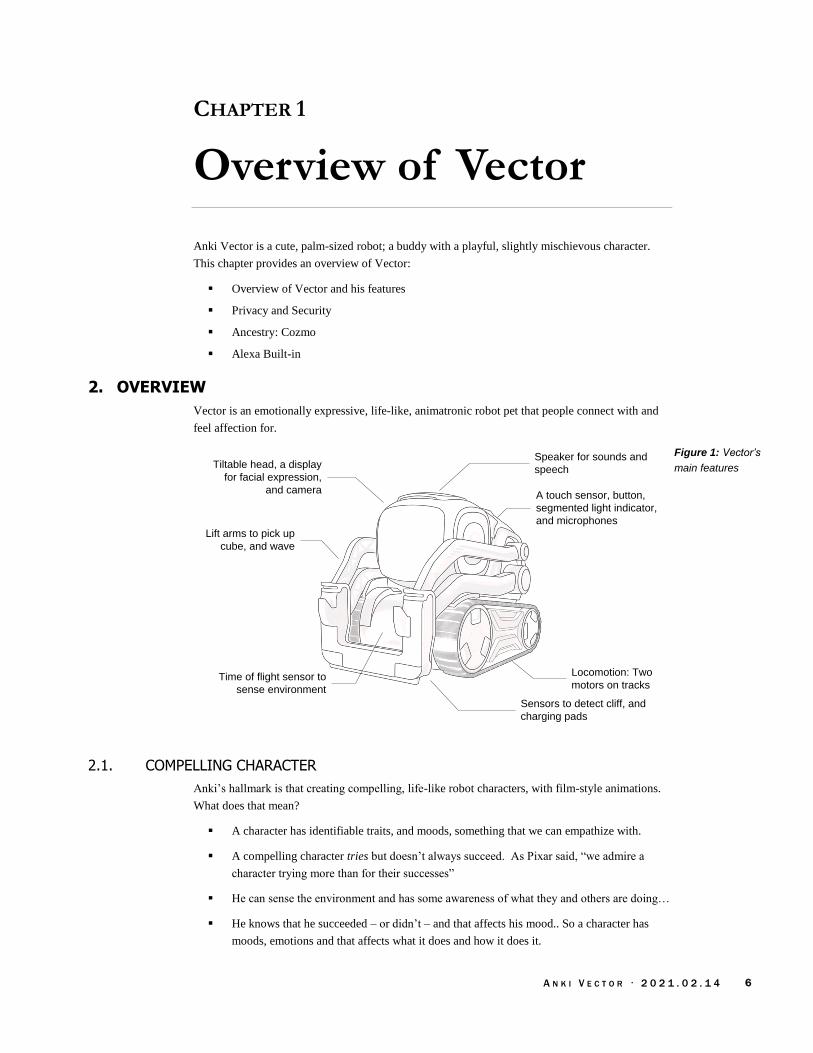
A N K I V E C T O R · 2 0 2 1 . 0 2 . 1 4 6
CHAPTER 1
Overview of Vector
Anki Vector is a cute, palm-sized robot; a buddy with a playful, slightly mischievous character.
This chapter provides an overview of Vector:
Overview of Vector and his features
Privacy and Security
Ancestry: Cozmo
Alexa Built-in
2. OVERVIEW
Vector is an emotionally expressive, life-like, animatronic robot pet that people connect with and
feel affection for.
A touch sensor, button,
segmented light indicator,
and microphones
Tiltable head, a display
for facial expression,
and camera
Sensors to detect cliff, and
charging pads
Time of flight sensor to
sense environment
Locomotion: Two
motors on tracks
Lift arms to pick up
cube, and wave
Speaker for sounds and
speech
2.1. COMPELLING CHARACTER
Anki’s hallmark is that creating compelling, life-like robot characters, with film-style animations.
What does that mean?
A character has identifiable traits, and moods, something that we can empathize with.
A compelling character tries but doesn’t always succeed. As Pixar said, “we admire a
character trying more than for their successes”
He can sense the environment and has some awareness of what they and others are doing…
He knows that he succeeded – or didn’t – and that affects his mood.. So a character has
moods, emotions and that affects what it does and how it does it.
Figure 1: Vector’s
main features

A N K I V E C T O R · 2 0 2 1 . 0 2 . 1 4 7
A living thing is never entirely at rest or silent; even when sleeping it moves a little and
makes little sounds
Movements vary and are never quite the same. When they look repetitive, they break the
illusion. This is true for choices, reactions and other behaviors too.
There are little motions, sounds and body’s affect that anticipate what a character is
thinking and going to do
Vector has a wide variety of behaviors, little motions (animations), and even some emotions that
give him a personality. He can express emotions thru expressive eyes (on an LCD display), raising
and lower his head, sounds, wiggling his body (by using his treads), or lifting his arms… or
shaking them. He can sense surrounding environment, interact and respond to it. He can
recognize his name1, follow the gaze of a person looking at him, and seek petting.2
2.2. FEATURES
Although cute, small, and affordable,3 Vector’s design is structured like many other robots.
He has a set of operator inputs:
A touch sensor is used detect petting
Internal microphone(s) to listen, hear commands and sense the ambient activity level
A button that is used to turn Vector on, to cause him to listen – or to be quiet (and not
listen), to reset him (wiping out his robot-specific information).
He can detect his arms and head being raised or lowered.
He has a set of indicators/annunciators:
Segmented lights on Vector’s backpack are used to indicate when he is on, needs the
charger, has heard the wake word, is talking to the Cloud, can’t detect WiFi, is booting, is
resetting (wiping out his personality and robot-specific information).
An LCD display, primarily to show eyes of a face. Robot eyes were Anki’s strongest piece
of imagery. Vector smiles and shows a range of expressions with his eyes.
Speaker for cute sounds and speech synthesis
He has other means to express affect as well:
His head can be tilted up and down to represent sadness, happiness, etc.
His arms flail to represent frustration
He can use his treads to shake or wiggle, usually to express happiness or embarrassment
He has environmental sensors:
A camera is used to map the area, detect and identify objects and faces.
Fist-bump and being lifted can be detected using an internal inertial measurement unit
(IMU)
A forward facing “time of flight” proximity sensor aids in mapping and object avoidance
1 Vector can’t be individually named. 2 Admittedly this is a bit hit and miss. 3 Although priced as an expensive toy, this feature set in a robot is usually an order of magnitude more expensive, with less quality.

A N K I V E C T O R · 2 0 2 1 . 0 2 . 1 4 8
Ground sensing proximity sensors that are used to detect cliffs at the edge of his area and
to following lines when he is reversing onto his charger.
His internal sensing includes:
Battery voltage, charging; charging temperature
IMU for orientation and position (6-axis) tracking
Encoders provide feedback on motor rotation
His other articulation & actuators are:
Vector drives using two independent treads to do skid-steering
Using his arms Vector can lift or flip a cube; he can pop a wheelie, or lift himself over a
small obstacle.
Vector can raise and lower his head
Communication (other than user facing):
Communication with the external world is thru WiFi and Bluetooth LE.
Internally RS-232 (CMOS levels) and USB
Motion control
At the lowest level can control each of the motors speed, degree of rotation, etc. This
allows Vector to make quick actions.
Combined with the internal sensing, he can drive in a straight line and turn very tightly.
Driving is done using a skid-steering, kinematic model
To do all this, the motion control takes in feedback from the motor encoder, IMU-
gyroscope. May also use the image processing for SLAM-based orientation and
movement.
Guidance, path planning
Vector plans a route to his goals – if he knows where his goal is – along a path free of
obstacles; he adapts, moving around in changing conditions.
A*, Rapidly-Expanding Random Tree (RRT), D*-lite
Paths are represented as arcs, line segments, and turn points
Mapping and Navigation:
Maps are built using simultaneous location and mapping (SLAM) algorithms, using the
camera and IMU gyroscope movement tracking, time of flight sensor to measure distances,
and particle system algorithms to fill in the gaps.
The maps are represented uses quad-tree (position, pose)
Behaviour system:
Variety of behaviors animations
Goals, linking up to the guidance system to accomplish them
A simple emotion model to drive selection of behaviours

A N K I V E C T O R · 2 0 2 1 . 0 2 . 1 4 9
Emotion model. Dimensions to emotional state:
Happy (also referred to as his default state)
Confident
Social
Stimulated
Vision. This is one of Anki’s hallmarks: they used vision where others used beacons. For instance,
iRobot has a set of IR beacons to keep the robots of out areas, and to guide it to the dock. Mint has
an IR beacon that the mint robots use to navigate and drive in straight lines. Although Vector’s
companion cube is powered, this is not used for localization. It has markers that are visually
recognized by Vector.
Illumination sensing
Motion sensing
Links to Navigation system for mapping, (SLAM etc)
Recognizing marker symbols in his environment
Detecting faces and gaze detection allows him to maintain eye contact
3. PRIVACY AND SECURITY
Vector’s design includes a well thought out system to protect privacy. This approach protects the
following from strangers gaining access to:
Photos taken by Vector
The image stream from the camera
The audio stream from the microphone — if it had been finished being implemented
Information about the owner
Control of the robot’s movement, speech & sound, display, etc.
Vector’s software is protected from being altered in a way that would impair its ability to secure
the above.
4. COZMO
We shouldn't discuss Vector without mentioning the prior generation. Vector’s body is based
heavily on Cozmo; the mechanical refinements and differences are relatively small. Vector’s
software architecture also borrows from Cozmo and extends it greatly. Many of Vector’s
behaviours, senses, and functions were first implemented in Cozmo (and/or in the smartphone
application). One notable difference is that Cozmo did not include a microphone.
Cozmo includes a wide variety of games, behaviours, and ~940 animation scripts. Cozmo’s engine
is reported to be “about 1.8 million lines of code, the AI, computer vision, path planning,
everything.”4 This number should be discounted somewhat, as it likely includes many large 3rd
party modules… Nonetheless, it represents the scale of work to migrate Cozmo’s code base for
reuse in Vector.
4 https://www.reddit.com/r/IAmA/comments/7c2b5k/were_the_founders_of_anki_a_robotics_and_ai/
A N K I V E C T O R · 2 0 2 1 . 0 2 . 1 4 10
Not all of Cozmo’s functionality was ported to Vector at one time. Instead, key features and
behaviours were incrementally brought to Vector in its regular software updates. It is likely the
intent was to follow-up with much more in future updates, piling on features until September and
then switch to a focus on bug fixes and stability for the upcoming Christmas sales. This was,
perhaps, a faster schedule than they were able to deliver.
5. ALEXA INTEGRATION
Vector includes Amazon Alexa functionality, but it is not intimately integrated. Vector only acts
like an Echo Dot, as pass thru for Alexa service. By using the key word “Alexa,” Vector will
suppress his activity, face and speech, and the Alexa functionality takes over. Vector has no
awareness of Alexa’s to-do list, reminders, messages, alarms, notifications, question-and-answers,
and vice-versa; nor can he react to them.
The most likely reason for including Alexa is the times: everything had to include Alexa to be hip,
or there would be great outcry. Including Alexa may have also been intended to provide
functionality and features that Anki couldn’t, to gain experience with the features that Amazon
provides, and (possibly) with the intent to more tightly integrate those features into Anki products
while differentiating themselves in other areas.
Alexa clearly took a lot of effort to integrate, and a lot of resources:
“[Alexa Voice Service] solutions for Alexa Built-in products required expensive
application processor-based devices with >50MB memory running on Linux or Android”5
Alexa’s software resources consume as much space as Vector’s main software. And the software
is not power efficient. Even casual use of Alexa noticeably reduces battery life, and (anecdotally)
increases the processor temperature.
See Appendix C for a list for a list of the Alexa modules.
5 https://aws.amazon.com/blogs/iot/introducing-alexa-voice-service-integration-for-aws-iot-core/
Alexa’s SDK and services have continued to evolve. New Alexa SDKs allow simpler processors and smaller code by acting as little more than a remote microphone.

A N K I V E C T O R · 2 0 2 1 . 0 2 . 1 4 11
PART I
Electronics Design
This part provides an overview of the design of the electronics in Vector and his accessories
VECTOR’S ELECTRONICS DESIGN. An overview of the Vector’s electronics design.
HEAD-BOARD ELECTRONICS DESIGN. A detailed look at the electronics design of Vector’s
main processing board.
BACKPACK & BODY-BOARD ELECTRONICS DESIGN. A detailed look at the electronics design of
Vector’s backpack and motor driver boards.
ACCESSORY ELECTRICAL DESIGN. A look at the electrical design of Vectors accessories.
Note: In previous versions called the circuit board in the bottom half the “base-board”. It is now
referred to as “body-board” to match Anki’s naming

A N K I V E C T O R · 2 0 2 1 . 0 2 . 1 4 12
[This page is intentionally left blank for purposes of double-sided printing]
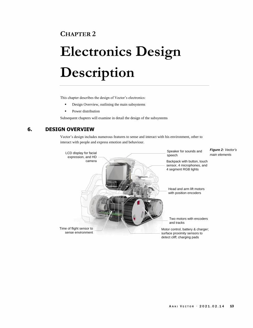
A N K I V E C T O R · 2 0 2 1 . 0 2 . 1 4 13
CHAPTER 2
Electronics Design
Description
This chapter describes the design of Vector’s electronics:
Design Overview, outlining the main subsystems
Power distribution
Subsequent chapters will examine in detail the design of the subsystems
6. DESIGN OVERVIEW
Vector’s design includes numerous features to sense and interact with his environment, other to
interact with people and express emotion and behaviour.
Backpack with button, touch
sensor, 4 microphones, and
4 segment RGB lights
LCD display for facial
expression, and HD
camera
Head and arm lift motors
with position encoders
Speaker for sounds and
speech
Two motors with encoders
and tracks
Motor control, battery & charger;
surface proximity sensors to
detect cliff; charging pads
Time of flight sensor to
sense environment
Figure 2: Vector’s
main elements

A N K I V E C T O R · 2 0 2 1 . 0 2 . 1 4 14
Vector’s functional elements are:
Element Description
backpack The top of Vector, where he has a button, segmented lights, and a touch sensor.
battery An internal battery pack is used as Vector’s source of energy.
button A momentary push button is used to turn Vector on, to cause him to listen – or to be quiet (and
not listen) – to reset him (wiping out his personality and robot-specific information).
camera Vector uses an HD camera to visualize his environment, and recognize his human companions.
charging pad Two pads on the bottom are used to replenish the energy in the battery pack from the dock.
The pads also serve as the communication interface during some manufacturing test steps.
LCD display An IPS LCD, with an active area is 23.2mm x 12.1mm. It has a resolution of 184 x 96 pixels,
with RGB565 color.
microphones There are 4 internal far-field microphone(s) to listen to commands and ambient activity level.
Employs beam forming to localize sounds.
motors & encoders There are four motors each with single-step optical encoders to measure their position and
approximate speed. One motor controls the tilt of the head assembly. Another controls the lift
of his arms. Two are used to drive him in a skid-steering fashion.
segmented RGB lights
There are 4 LEDs used to indicate when he is on, needs the charger, has heard the wake word,
is talking to the Cloud, can’t detect WiFi, is booting, is resetting (wiping out his robot-specific
information).
speaker A speaker is used to play sounds, and for speech synthesis
surface proximity sensors
4 infrared proximity sensors are used to detect the surface beneath Vector – and to detect drop
offs (“cliffs”) at the edge of his driving area, and to follow lines.
time of flight sensor A time of flight sensor is used to aid in mapping (by measuring distances) and object
avoidance.
touch sensor A touch allows Vector to detect petting and other attention.
Table 2: Vector’s main
elements
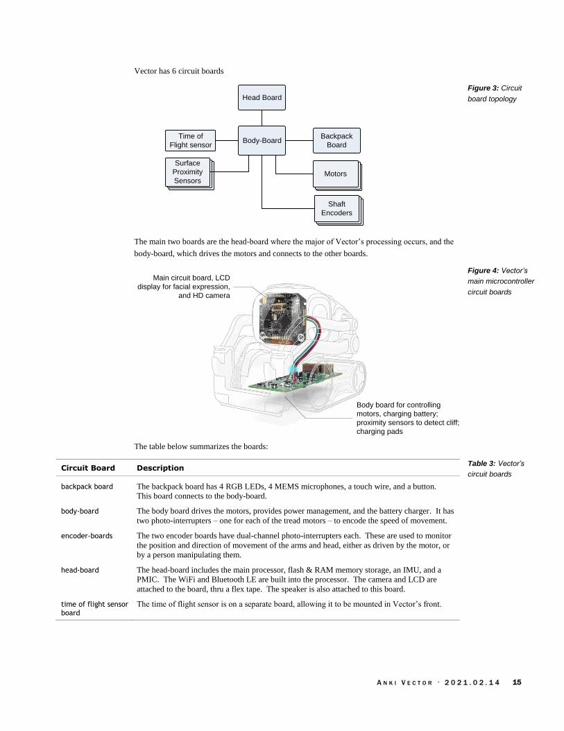
A N K I V E C T O R · 2 0 2 1 . 0 2 . 1 4 15
Vector has 6 circuit boards
Body-BoardBackpack
Board
Head Board
4 Motors4 MotorsMotors
4 Motors4 MotorsShaft
Encoders
4 Motors4 Motors
Surface
Proximity
Sensors
Time of
Flight sensor
The main two boards are the head-board where the major of Vector’s processing occurs, and the
body-board, which drives the motors and connects to the other boards.
Body board for controlling
motors, charging battery;
proximity sensors to detect cliff;
charging pads
Main circuit board, LCD
display for facial expression,
and HD camera
The table below summarizes the boards:
Circuit Board Description
backpack board The backpack board has 4 RGB LEDs, 4 MEMS microphones, a touch wire, and a button.
This board connects to the body-board.
body-board The body board drives the motors, provides power management, and the battery charger. It has
two photo-interrupters – one for each of the tread motors – to encode the speed of movement.
encoder-boards The two encoder boards have dual-channel photo-interrupters each. These are used to monitor
the position and direction of movement of the arms and head, either as driven by the motor, or
by a person manipulating them.
head-board The head-board includes the main processor, flash & RAM memory storage, an IMU, and a
PMIC. The WiFi and Bluetooth LE are built into the processor. The camera and LCD are
attached to the board, thru a flex tape. The speaker is also attached to this board.
time of flight sensor board
The time of flight sensor is on a separate board, allowing it to be mounted in Vector’s front.
Figure 3: Circuit
board topology
Figure 4: Vector’s
main microcontroller
circuit boards
Table 3: Vector’s
circuit boards
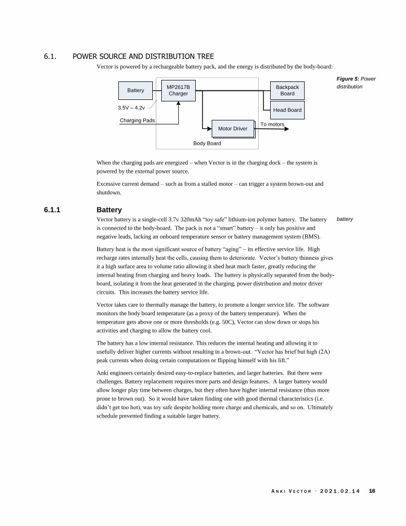
A N K I V E C T O R · 2 0 2 1 . 0 2 . 1 4 16
6.1. POWER SOURCE AND DISTRIBUTION TREE
Vector is powered by a rechargeable battery pack, and the energy is distributed by the body-board:
BatteryMP2617B
Charger
Backpack
Board
Head Board
Charging Pads
3.5V – 4.2v
Body Board
Motor DriverTo motors
When the charging pads are energized – when Vector is in the charging dock – the system is
powered by the external power source.
Excessive current demand – such as from a stalled motor – can trigger a system brown-out and
shutdown.
6.1.1 Battery
Vector battery is a single-cell 3.7v 320mAh “toy safe” lithium-ion polymer battery. The battery
is connected to the body-board. The pack is not a “smart” battery – it only has positive and
negative leads, lacking an onboard temperature sensor or battery management system (BMS).
Battery heat is the most significant source of battery “aging” – its effective service life. High
recharge rates internally heat the cells, causing them to deteriorate. Vector’s battery thinness gives
it a high surface area to volume ratio allowing it shed heat much faster, greatly reducing the
internal heating from charging and heavy loads. The battery is physically separated from the body-
board, isolating it from the heat generated in the charging, power distribution and motor driver
circuits. This increases the battery service life.
Vector takes care to thermally manage the battery, to promote a longer service life. The software
monitors the body board temperature (as a proxy of the battery temperature). When the
temperature gets above one or more thresholds (e.g. 50C), Vector can slow down or stops his
activities and charging to allow the battery cool.
The battery has a low internal resistance. This reduces the internal heating and allowing it to
usefully deliver higher currents without resulting in a brown-out. “Vector has brief but high (2A)
peak currents when doing certain computations or flipping himself with his lift.”
Anki engineers certainly desired easy-to-replace batteries, and larger batteries. But there were
challenges. Battery replacement requires more parts and design features. A larger battery would
allow longer play time between charges, but they often have higher internal resistance (thus more
prone to brown out). So it would have taken finding one with good thermal characteristics (i.e.
didn’t get too hot), was toy safe despite holding more charge and chemicals, and so on. Ultimately
schedule prevented finding a suitable larger battery.
Figure 5: Power
distribution
battery
A N K I V E C T O R · 2 0 2 1 . 0 2 . 1 4 17
6.1.2 Battery management
The MP2617B is a central element to managing the battery. It acts as a battery charger, a power
switch and power converter for the whole system.
When Vector is going into an off state – such as running too low on power, going into a
ship state before first use, or has been turned off by a human companion – the MP2617B
charger and power converted can be signaled to turn off.
When Vector is turned off the boards are not energized. The exception is that the high side
of the push button is connected to the battery. When closed, the signals the MP2617B to
connect the battery to the rest of the system, powering it up.
The MP2617B is also responsible for charging the battery. There are two pads that mate
the dock to supply energy to charge the battery.
In many rechargeable lithium ion battery systems there is a coulomb counter to track the state of
charge. Vector does not have one. The need for recharge is triggered solely on the battery voltage.
6.2. MANUFACTURING TEST SUPPORT
Vector has an interface for test and manufacturing. The charging pads allow limited
communication with the software. This supports DVT testing, manufacturing tests, as well as
entering the serial number and other per unit information. This access is removed after
manufacturing test.
7. REFERENCES & RESOURCES
Anki, Lithium single-cell battery data sheet
https://support.anki.com/hc/article_attachments/360018003653/Material%20Safety%20Data
%20Sheet_April%202018.pdf

A N K I V E C T O R · 2 0 2 1 . 0 2 . 1 4 18
CHAPTER 3
Head-board
Electronics Design
Description
This chapter describes the electronic design of Vector’s head-board:
Detailed design of the head-board
8. THE HEAD-BOARD (THE MAIN PROCESSOR BOARD)
The head-board handles the display, playing sounds, communication, and all of Vector’s real
processing. It is powered by a quad-core Arm-A7 Qualcomm APQ8009 microprocessor. The
processor also connects to Bluetooth LE and WiFi transceivers, an HD camera, LCD display,
speakers and an IMU.
APQ8009 Microprocessor
UART
PM8916
PMIC
Vpwr
Body-Board
Communication
SP
I0
Camera
IMU
LCD
Flash/RAM
Bluetooth WiFi
UARTConsole UART
USBUSB
SPI1
Speaker
LCD
backlight
MIP
I
I2C
6
SD
HC
1
Figure 6: Head-board
block diagram

A N K I V E C T O R · 2 0 2 1 . 0 2 . 1 4 19
The head-board’s functional elements are:
Element Description
Bluetooth LE transceiver
A Bluetooth LE transceiver is built into the package
camera Vector uses a 720P camera to visualize his environment and recognize his human companions.
flash/RAM (eMMC) Flash and RAM are provided by single external package, a Kingston 04EMCP04-NL3DM627
mixed memory chip with 4 GB flash and 512MB RAM.
inertial measurement unit (IMU)
The headboard includes a 6-axis IMU – gyroscope and accelerometer – used for navigation and
motion control.
LCD backlight There are two LEDs used to illuminate the LCD display.
LCD display An IPS LCD, with an active area is 23.2mm x 12.1mm. It has a resolution of 184 x 96 pixels,
with RGB565 color.
microprocessor The head-board is based on a Qualcomm APQ8009 (Snapdragon 212). The processor is a
quad-core Arm A7 (32-bit) CPU.
power management IC (PMIC)
The PM8916 power management IC provides voltage regulation for the processor, flash/RAM
and other parts; it also provides audio out to the speaker and controls the LCD backlight.
speaker A speaker is used to play sounds, and for speech synthesis
WiFi transceiver An 802.11AC WiFi transceiver is built into the processor package
8.1. THE APQ8009 PROCESSOR
The head-board is based on the Qualcomm “Snapdragon 212” APQ8009 SOC. It is a quad-core
processor; each core is a 32-bit ARM Cortex A7. It also includes a DSP (“Hexagon 536”), and
GPU (Adreno 304); these are not used by the software. It also includes WiFi and Bluetooth LE
transceivers. The processor has interfaces to external memory, for the camera (using MIPI), the
display, and the audio playback.
The APQ8009 processor is a sibling to the MSM8909 processor employed in cell phones, where
APQ is short for “Application Processor Qualcomm” and MSM is short for “Mobile Station
Modem.” The difference is that the later includes some form of modem, such as HPSA, CDMA,
or LTE. Both designators are used in software code-bases employed by Vector. The most likely
reason is the naming of registers, drivers, and other useful software didn't carefully limit the use of
MSMxxxx references to just the processors with modems.
The flash & RAM are connected to the processor on SDHC1. The device tree file shows that
during development Vector’s also supported an SD card slot on SDHC2.
The processor dynamically adjusts its clock frequency, within an allowed region. The processor
can be configured to limit its speed.
8.2. SPEAKER
The speaker is driven at 16bits, single channel, with a sample rate of 8000-16025 samples/sec.
Table 4: The head-
boards functional
elements

A N K I V E C T O R · 2 0 2 1 . 0 2 . 1 4 20
8.3. CAMERA
Vector has a 720p camera with a 120° field of view. The camera is calibrated at manufacturing
time. The camera vertical sync (frame sync) is connected to the interrupt input on the IMU to
synchronize the samples.
GPIO Description
26 Camera interface clock
48 Camera reset
83 Camera power enable (from PM8916 PMIC)
94 Camera standby
8.4. THE LCD
Vector’s LCD is a backlit IPS display assembly made by Truly. The processor is connected to
the LCD via SPI. Two LEDs are used to illuminate the LCD. The backlight is PWM controlled
by the PM8916 PMIC.
The prior generation, Cozmo, used an OLED display for his face and eyes. This display had the
strengths of high contrast and self-illumination. However, OLEDs are susceptible to burn-in and
uneven dimming or discoloration of overused pixels. Anki addressed this with two
accommodations. First it gave the eyes regular motion, looking around and blinking. Second, the
LCD’s illuminated rows were regularly alternated to give a retro-technology interlaced row effect,
like old CRTs.
Vector’s IPS display gives a smoother imagery – Cozmo’s OLED was simply black and white.
The LCD is also much less susceptible to burn-in, at the expense of higher power. Vector’s LCD
can also develop dead lines (or pixels) that grow in number until the display is non-functional.
Some units have a defective LCD, where the glass is not properly sealed. This allows moisture in,
causing progressive damage to the LCD. It is also speculated that these lines come from shocks to
the head, causing breaks in the LCD connections.
8.5. POWER MANAGEMENT
The PM8916 PMIC is responsible for providing power and managing most of the power. The
headboard is capable of being the highest power consumer in Vector. By limiting the clock rate of
the processor, the power use can be capped.
The headboard can be put into a lower power state by reducing the clock rate of processor and
using its sleep features; dimming or turning off the LCD, and reducing the camera frame rate (or
turning it off). The APQ8009 processor has many sophisticated power controls, but these were not
fully realized in Vector’s software.
8.6. TRIM, CALIBRATION SERIAL NUMBERS AND KEYS
Each Vector has a set of per unit calibrations:
The camera is calibrated
The IMU is calibrated
Table 5: The camera
controls
LCD display
US Patent 20372659

A N K I V E C T O R · 2 0 2 1 . 0 2 . 1 4 21
The motor position is calibrated, this is performed with each startup
There are per unit keys, MAC addresses and serial numbers
Each processor has its own unique key called the silicon-based hardware key (SHK),
burned into its fuse mask. This key is used to with the Trust Zone, and secure boot; but it
is not accessible outside of these. There are several modules (trustlets) that must run in the
TrustZone, most provide security on keys that the main system uses. Each of these
trustlets are signed with a certificate chain that is rooted in the unique hardware key. (That
is, they cannot be copied and used on another processor.)
The WiFi and Bluetooth have assigned, unique MAC addresses.
Each Vector has an assigned serial number
8.7. MANUFACTURING TEST CONNECTOR/INTERFACE
It is a common practice to include at least one interface on a product for use during manufacture.
This is used to load software and firmware, unique ids – WiFi MACs, serial number – to perform
any calibration steps and to perform run-up checks that the device functions / is assembled
correctly. It is intended to be a fast interface that doesn’t cause yield fallout. Typically (but there
are exception) this is not radio based, as they can interfere or have fiddly issues.
The USB interface is used to load firmware. The microprocessors include a built-in boot-loader
(ABOOT), which includes support for loading firmware into the devices flash.
For the other functions, there are three possibilities
There is a UART, that provides a boot console, but does not accept input
There is a USB connector that probably is used to load firmware.
The WiFi, once MAC addresses have been loaded into the unit
9. REFERENCES & RESOURCES
Kingston Technology, Embedded Multi-Chip Package 04EMCP04-NL3DM627-Z02U, rev 1.2,
2016
https://cdn.discordapp.com/attachments/573889163070537750/595223765206433792/04EM
CP04-NL3DM627-Z02U_-_v1.2.pdf
Qualcomm, APQ8009 Processor
https://www.qualcomm.com/products/apq8009
Qualcomm, PM8916/PM8916-2 Power Management ICs Device Specification, Rev C, 2018 Mar
13
https://developer.qualcomm.com/qfile/29367/lm80-p0436-
35_c_pm8916pm8916_power_management_ics.pdf
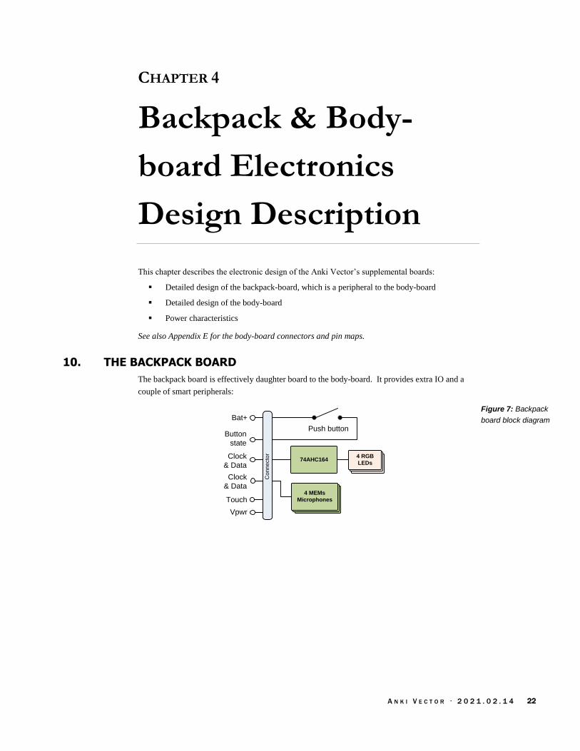
A N K I V E C T O R · 2 0 2 1 . 0 2 . 1 4 22
CHAPTER 4
Backpack & Body-
board Electronics
Design Description
This chapter describes the electronic design of the Anki Vector’s supplemental boards:
Detailed design of the backpack-board, which is a peripheral to the body-board
Detailed design of the body-board
Power characteristics
See also Appendix E for the body-board connectors and pin maps.
10. THE BACKPACK BOARD
The backpack board is effectively daughter board to the body-board. It provides extra IO and a
couple of smart peripherals:
Bat+
Push buttonButton
state
74AHC164
Touch
Clock
& Data
Vpwr
4 RGB
LEDs
4 RGB
LEDs
4 RGB
LEDs
4 MEMs
Microphones
4 MEMs
Microphones
4 MEMs
Microphones
Clock
& Data
Co
nn
ecto
r
Figure 7: Backpack
board block diagram

A N K I V E C T O R · 2 0 2 1 . 0 2 . 1 4 23
The table below summarizes the functional elements of the backpack board:
Elements Description
74AHC164 A SPI-like GPIO expander. This is used to drive the RGB LEDs.
microphones There are 4 far-field MEMS PDM microphones. The microphones are accessed via SPI, in an
output only mode. These are designated MK1, MK2, MK3, MK4
push button A momentary push button is connected to the battery terminal, allowing a press to wake
Vector, as well as signal the processor(s).
RGB LEDs There are 4 RGB LEDs to make up a segmented display. Each segment can be illuminated
individually (in a time multiplexed manner) or may share a colour configuration with its
counterparts.
touch sensor A touch-sensing wire (and passive components)
10.1. BACKPACK CONNECTION
The backpack connection includes:
Power and ground connections. This includes connection to the battery rail.
The touch wire as an analog signal to the body-board
A quasi digital signal out from the momentary push button
A SPI-like clock, two master-in-slave-out (MISO) signals for the microphones
A SPI-like clock and master-out-slave-in (MOSI) for the 74AHC164 LED controller
10.2. ELECTRO-STATIC DISCHARGE (ESD) PROTECTION
The touch sensing uses an insulated wire separated from the external touch plate. There is no
direct path of conduction from the external plate for ESD. The separation reduces transient voltage
to levels that the electronics can suppress.
10.3. OPERATION
The touch sensor conditioning and sensing is handled by the body-board. The touch sense wire is
merely an extension from the body-board through the backpack board.
The push-button is wired to the battery. When pressed, the other side of the push button signals
both body-board microcontroller, and (if Vector is off) the charger chip to connect power. The
theory of operation will be discussed further in the body-board section below.
The 74AHC164 serial-shift-register is used as a GPIO expander. It takes a clock signal and serial
digital input, which are used to control up to 8 outputs. The inputs determine the state of 8 digital
outputs used to control the RGB LEDs.
Each of the 4 MEMS microphones take a clock signal, and provide a serial digital output. The
body-board reads all four microphones by simultaneously. (This will be discussed in the body-
board section).
Table 6: Backpack
board functional
elements
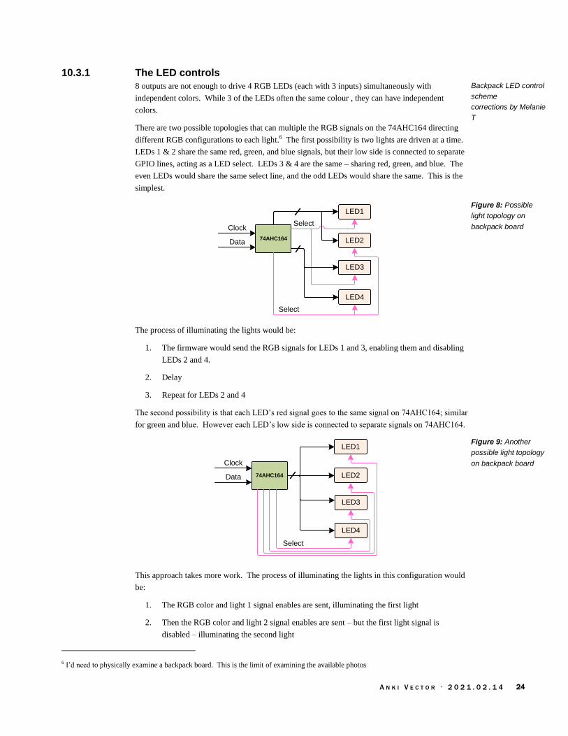
A N K I V E C T O R · 2 0 2 1 . 0 2 . 1 4 24
10.3.1 The LED controls
8 outputs are not enough to drive 4 RGB LEDs (each with 3 inputs) simultaneously with
independent colors. While 3 of the LEDs often the same colour , they can have independent
colors.
There are two possible topologies that can multiple the RGB signals on the 74AHC164 directing
different RGB configurations to each light.6 The first possibility is two lights are driven at a time.
LEDs 1 & 2 share the same red, green, and blue signals, but their low side is connected to separate
GPIO lines, acting as a LED select. LEDs 3 & 4 are the same – sharing red, green, and blue. The
even LEDs would share the same select line, and the odd LEDs would share the same. This is the
simplest.
LED1
LED274AHC164
LED3
LED4
Select
Select
Clock
Data
The process of illuminating the lights would be:
1. The firmware would send the RGB signals for LEDs 1 and 3, enabling them and disabling
LEDs 2 and 4.
2. Delay
3. Repeat for LEDs 2 and 4
The second possibility is that each LED’s red signal goes to the same signal on 74AHC164; similar
for green and blue. However each LED’s low side is connected to separate signals on 74AHC164.
LED1
LED274AHC164
LED3
LED4
Select
Clock
Data
This approach takes more work. The process of illuminating the lights in this configuration would
be:
1. The RGB color and light 1 signal enables are sent, illuminating the first light
2. Then the RGB color and light 2 signal enables are sent – but the first light signal is
disabled – illuminating the second light
6 I’d need to physically examine a backpack board. This is the limit of examining the available photos
Backpack LED control
scheme
corrections by Melanie
T
Figure 8: Possible
light topology on
backpack board
Figure 9: Another
possible light topology
on backpack board

A N K I V E C T O R · 2 0 2 1 . 0 2 . 1 4 25
3. This is repeated for each of the other lights.
With either approach, if the switching between the LED’s is done quickly enough – in a short time
interval – the off period isn’t visible. LED’s don’t immediate turn off, rather their brightness
decays over a short period. And the human eye doesn’t perceive short flickers. Although the
lights are “pulse width modulated” – they are turned off a portion of the time, dimming them –
current limiting resistors may have been set to achieve the desired maximum brightness for the
fastest multiplexing time.
The body-board controller can dim the brightness of the LEDs further by choosing larger numbers
of time slots to not illuminate a light.
11. THE BODY-BOARD
The body board is a battery charger, smart IO expander, and motor controller. It connects the
battery to the rest of the system and is responsible for charging it. It is based on an STM32F030
which acts as second processor in the system.
Push button
74AHC164 4 RGB
LEDs
4 RGB
LEDs
4 RGB
LEDs
4 MEMs
Microphones
4 MEMs
Microphones
4 MEMs
Microphones
Battery
STM32F030
Microcontroller
(system controller)
I2C
AD
C
UART
GP
IO
GP
IO
Backpack Board
SPI
Battery
Switch
4 Motor
Drivers
4 Motor
Drivers
4 Motor
Drivers 4 Motors4 Motors4 Motors
MP2617B
Charger
4 Motors4 Motors
4 Optical
shaft
Encoders
Vpwr
Regulator
Charging
Terminal
Reverse
Polarity
Protection
ADC
Touch
ES
D P
rote
ctio
n
4 Motors4 Motors
4 Surface
Proximity
Sensors
Time of Flight
Sensor
Head-Board
CommunicationPWM/
GPIO
I2C
/
SP
I Counter
GPIO
Figure 10: Body-
board block diagram

A N K I V E C T O R · 2 0 2 1 . 0 2 . 1 4 26
The functional elements of the body-board are:
Element Description
battery An internal, rechargeable battery pack (3.7v 320 mAh)
battery switch Used to disconnect the battery to support off-mode (such as when stored) and to reconnect the
battery with a button press.
charging pad Two pads on the bottom are used to replenish the energy in the battery pack from the dock.
The right, positive charging pad acts a communication interface as well.
motor driver There are four motor drivers, based on an H-bridge design. This allows a motor to be driven
forward and backward.
motors There are four motors: one motor controls the tilt of the head assembly; another controls the
lift of his arms; and two are used to drive him in a skid-steering fashion.
MP2617B charger The Monolithic Power Systems MP2617B serves as the battery charger. It provides a state of
charge to the microcontroller. It also directs power from the charging pads to the rest of the
system while the robot is on the charging dock.
optical shaft encoder The 4 shaft encoders are implemented with photo-interrupters, in conjunction with a slotted
disc on a motor’s shaft, is used to measure the amount a shaft has turned, and its speed. The
two tread motors use a Sharp GP1S092HCPIF photo-interrupter. The lift and head motors use
a dual-channel photo-interrupter to allow discerning the direction of rotation.
regulator A 3.3v regulator is used to supply power to the microcontroller and logical components.
reverse polarity protection
Protects the circuitry from energy being applied to the charging pads in reverse polarity, such
as putting Vector onto the charging pads in reverse.
STM32F030 microcontroller
The “brains” of the body-board, used to drive the motors, and RGB LEDs; to sample the
microphones, time of flight sensor, proximity sensor, temperature, and the touch sense;, and
monitoring the battery charge state. It communicates with the head-board.
surface proximity sensors
4 infrared proximity sensors are used to detect the surface beneath Vector – and to detect drop
offs (“cliffs”) at the edge of his driving area and to follow lines.
VL53L0x time of flight sensor
A ST Microelectronics VL53L0x time of flight sensor is used to measure distance to objects in
front of Vector. This sensor is connected by I2C.
11.1. POWER MANAGEMENT
The battery charging is based on a MP2617B IC, which also provides some protection functions.
There is no Coulomb counter; the state of charge is based solely on the battery voltage.
11.1.1 Protections
The charging pads have reverse polarity protection.
The MP2617B has an over-current cut off. If the current exceeds ~5A (4-6A), the battery will be
disconnected from the system bus. Such a high-current indicates a short. There is no fuse.
The MP2617B has a low voltage cut off. If the battery voltage drops below ~2.4 (2.2-2.7V) the
battery will be disconnected from the system bus (TBD) until the battery voltage rises above ~2.6V
(2.4-2.8V).
The MP2617B may have a temperature sense. If the temperature exceeds a threshold, charging is
paused until the battery cools. The temperature sense is not on the battery. It would be on the
circuit board.
Table 7: The body-
board functional
elements
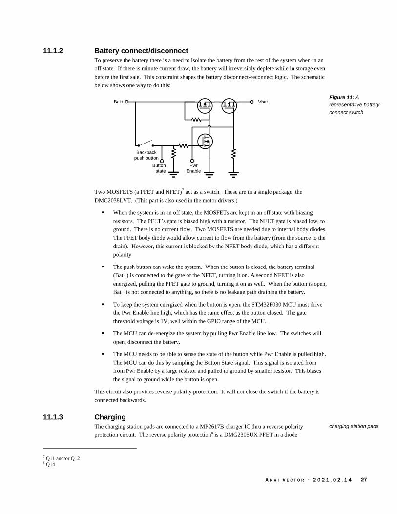
A N K I V E C T O R · 2 0 2 1 . 0 2 . 1 4 27
11.1.2 Battery connect/disconnect
To preserve the battery there is a need to isolate the battery from the rest of the system when in an
off state. If there is minute current draw, the battery will irreversibly deplete while in storage even
before the first sale. This constraint shapes the battery disconnect-reconnect logic. The schematic
below shows one way to do this:
VbatBat+
Backpack
push button
Button
state
Pwr
Enable
Two MOSFETS (a PFET and NFET)7 act as a switch. These are in a single package, the
DMC2038LVT. (This part is also used in the motor drivers.)
When the system is in an off state, the MOSFETs are kept in an off state with biasing
resistors. The PFET’s gate is biased high with a resistor. The NFET gate is biased low, to
ground. There is no current flow. Two MOSFETS are needed due to internal body diodes.
The PFET body diode would allow current to flow from the battery (from the source to the
drain). However, this current is blocked by the NFET body diode, which has a different
polarity
The push button can wake the system. When the button is closed, the battery terminal
(Bat+) is connected to the gate of the NFET, turning it on. A second NFET is also
energized, pulling the PFET gate to ground, turning it on as well. When the button is open,
Bat+ is not connected to anything, so there is no leakage path draining the battery.
To keep the system energized when the button is open, the STM32F030 MCU must drive
the Pwr Enable line high, which has the same effect as the button closed. The gate
threshold voltage is 1V, well within the GPIO range of the MCU.
The MCU can de-energize the system by pulling Pwr Enable line low. The switches will
open, disconnect the battery.
The MCU needs to be able to sense the state of the button while Pwr Enable is pulled high.
The MCU can do this by sampling the Button State signal. This signal is isolated from
from Pwr Enable by a large resistor and pulled to ground by smaller resistor. This biases
the signal to ground while the button is open.
This circuit also provides reverse polarity protection. It will not close the switch if the battery is
connected backwards.
11.1.3 Charging
The charging station pads are connected to a MP2617B charger IC thru a reverse polarity
protection circuit. The reverse polarity protection8 is a DMG2305UX PFET in a diode
7 Q11 and/or Q12 8 Q14
Figure 11: A
representative battery
connect switch
charging station pads
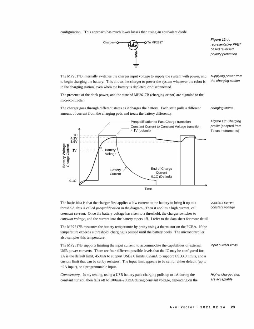
A N K I V E C T O R · 2 0 2 1 . 0 2 . 1 4 28
configuration. This approach has much lower losses than using an equivalent diode.
To MP2617Charger+
The MP2617B internally switches the charger input voltage to supply the system with power, and
to begin charging the battery. This allows the charger to power the system whenever the robot is
in the charging station, even when the battery is depleted, or disconnected.
The presence of the dock power, and the state of MP2617B (charging or not) are signaled to the
microcontroller.
The charger goes through different states as it charges the battery. Each state pulls a different
amount of current from the charging pads and treats the battery differently.
Time
Ba
tte
ry V
olt
ag
e
Ch
arg
e C
urr
en
t
1C4.1V
3V
0.1C
3.9V
Constant Current to Constant Voltage transition
4.1V (default)
End of Charge
Current
0.1C (Default)
Prequalification to Fast Charge transition
Battery
Voltage
Battery
Current
The basic idea is that the charger first applies a low current to the battery to bring it up to a
threshold; this is called prequalification in the diagram. Then it applies a high current, call
constant current. Once the battery voltage has risen to a threshold, the charger switches to
constant voltage, and the current into the battery tapers off. I refer to the data sheet for more detail.
The MP2617B measures the battery temperature by proxy using a thermistor on the PCBA. If the
temperature exceeds a threshold, charging is paused until the battery cools. The microcontroller
also samples this temperature.
The MP2617B supports limiting the input current, to accommodate the capabilities of external
USB power converts. There are four different possible levels that the IC may be configured for:
2A is the default limit, 450mA to support USB2.0 limits, 825mA to support USB3.0 limits, and a
custom limit that can be set by resistors. The input limit appears to be set for either default (up to
~2A input), or a programmable input.
Commentary. In my testing, using a USB battery pack charging pulls up to 1A during the
constant current, then falls off to 100mA-200mA during constant voltage, depending on the
Figure 12: A
representative PFET
based reversed
polarity protection
supplying power from
the charging station
charging states
Figure 13: Charging
profile (adapted from
Texas Instruments)
constant current
constant voltage
input current limits
Higher charge rates
are acceptable

A N K I V E C T O R · 2 0 2 1 . 0 2 . 1 4 29
head-board’s processing load. Stepped down to the ~4V battery the applied current at peak is
approximately 1A.9
With larger batteries this would be too high. Battery cells are normally charged at no more than a
“1C” rate – e.g. the battery maximum charge rate “should” be 320mA at max. Vector’s battery can
be charged at a rate higher than 1C. Heat is what damages batteries. This battery’s low internal
resistance doesn’t produce as much heat; and its large surface to volume ratio lets it shed heat.
11.1.4 Brown-out
The motor stall current is enough to cause Vector to brown-out and shut down unexpectedly.
This indicates two possible mechanisms:
If the system browns out the STM32F030, the MCU will no longer hold the power switch
closed, and the system power will be disconnected.
If the current exceeds a threshold, the MP2617B will disconnect power to the system. This
threshold is very high – ~5A – and is unlikely to ever be encountered in operation.
Commentary: It may be interesting to modify either the MCU’s Vdd to have a larger retaining
capacitor, or to add a current limiting mechanism for the motors, such as an inline resistor.
11.1.5 Reducing power
The sensors – the encoders, cliff sensors, and time of flight sensor – have power controls. This
allows them to be turned off to reduce power consumption. The time of flight sensor’s sampling
and communication interval can be controlled to greatly reduce power consumption, while still
providing measurements. The other sensors can be duty cycled to maintain a lower power use, but
still detect activity (albeit not measure it accurately).
11.2. ELECTRO-STATIC DISCHARGE (ESD) PROTECTION
The body-board employs a Vishay GMF05, TVS diode (U4) for electro-static discharge (ESD)
protection, likely on the pushbutton and touch input.
11.3. STM32F030 MICROCONTROLLER
The body-board is controlled by a STM32F030C8T6 microcontroller (MCU), in a LQFP48
package. This processor essentially acts as a smart IO expander and motor controller. The
microcontroller is also referred to as the system controller
The MCU’s digital inputs include:
4 photo-interrupters used as shaft encoders, one for each motor (left, right, head, lift)
Charger state
The MCU’s digital outputs include:
12 motors driver signals
Charger enable
Power controls for the sensors
9 Other reports suggest up to 2As into the battery, possible with the use of high-power USB adapters intended to support tablet recharge. As a preventative measure, I have a current limiter between my USB power adapter and Vector’s charging dock. 1Ω on the USB
power. I tried 1Ω -14Ω; these should have limited the current to 1A and 500mA respectively. Instead, Vector would only pull 40mA -
370mA; in many cases, not enough to charge. Most likely the resistor acted as a part of resistive divider and undermined the chargers feedback loops.
motor stall & brown
out effects

A N K I V E C T O R · 2 0 2 1 . 0 2 . 1 4 30
The MCU’s analog inputs include:
Touch sensor; the momentary push button works by pulling this signal high
Battery voltage
Charging pad voltage
Temperature sensor (measured internally)
The communication signals include:
2 SPI-like signals to LED outputs. Uses a clock and data line to send the state to the LEDs.
6 SPI from microphones – an SPI MCLK to clock out, a timer divider (in and out), and 2
MISO to receive state of the data from the microphones.
4 I2C pins for communication with the time of flight sensor and IR proximity sensors used
to detect cliffs and lines,
2 UART, for communication with the head board
Note: The microcontroller does not have an external crystal and uses an internal RC oscillator
instead.
11.3.1 Manufacturing test connections
The body-board includes SWD pads intended for programming at manufacturing time. After
programming, the firmware cannot be updated via the SWD pads (more on this below). The
firmware can only be updated via a boot-loader.
The body-board also provides RS232-style bidirectional communication that can be used issue
commands, query results, and store calibration and serial number information. See Chapter 12
Body-Board Communication Protocol for more information. The positive (right hand) charging
contact is used for this communication.10
11.3.2 Firmware updates
The firmware is referred to as “syscon” (as in “system controller”). The microcontroller includes a
boot loader, allowing the firmware to be updated by the head-board. The firmware can be updated
in OTA software releases.
STM32 Readout-protection is set to the highest level in the microcontroller. This is intended to
prevent a SWD-based reading or modification of the firmware (including the boot-loader). STM32
processors include a different boot-loader from ST as well; this alternative boot-loader will crash if
any access to program memory is attempted with the readout protection flags set. It is possible to
disable the read-out protection – but mass erasing the chip in the process – with physical access
and SWD tools.11 To extract the boot-loader will more skilled and invasive techniques.12
Future changes to the body-board firmware will require expertise. The STM32F030 firmware can
be analyzed using the syscon.dfu file (or be extracted with a ST-Link) and disassembled. Shy of
recreating the firmware source code, patches replacing a key instruction here and there with a jump
to the patch, created in assembly (most likely) code to fix or add feature, then jump back.
10 According to the forums, this is also present on Cozmo and Drive. 11 https://stackoverflow.com/questions/32509747/stm32-read-out-protection-via-openocd 12 https://rtfm.newae.com/Capture/ChipWhisperer-Nano/ https://www.cl.cam.ac.uk/~sps32/mcu_lock.html

A N K I V E C T O R · 2 0 2 1 . 0 2 . 1 4 31
Emulation (such as QEMU-STM32) , ST-link ($25) and a development environment will be
required to debug and modify the firmware initially. The development environment ranges from
free to several thousand dollars, the later being the more productive tools.
11.4. SENSING
11.4.1 Temperature sensing
The body-board measures temperature using the microcontrollers internal temperature sense. This
value is higher than the ambient, and can bounce around with activity. The firmware filters the
value to reduce the noise.
11.4.2 Time of Flight sensor
The MCU interfaces with a ST Microelectronics VL53L0x time of flight sensor, which can
measure the distance to objects in front of vector. It “has a usable range 30mm to 1200mm away
(max useful range closer to 300mm for Vector) with a field of view of 25 degrees.”
These sensors work by timing how long it takes for a coded pulse to return. The time value is then
converted to a distance. Items too close return the pulse faster than the sensor can measure. The
measured distance is available to the microcontroller over I2C.
11.4.3 Proximity sensing
Vector has 4 IR proximity sensors that are used to used to detect drops offs (“cliffs”) and to follow
lines. The exact model hasn’t been identified, but the Everlight EAAPMST3923A2 is a typical
proximity sensor. The sensor is an LED and IR detector pair. The sensor reports, via I2C, the
brightness sensed by the detector. A sensor often pulses its emitter, to reject to sunlight; and uses
a configurable threshold to reduce sensitivity to ambient light.
The IR proximity sensors all share the same I2C address. To address this, the body board does
something clever. The STM32F030 allows switching the pins that the I2C clock and data lines go
to. The cliff sensors are connected so that no two shares both the same data and clock line – that is
the clock and data lines combinations are unique to the device being talked with. The firmware
rotates thru which pins to use with I2C to talk to each of the four different cliff sensors. The pins on
the micro are reconfigured to use each of these.
11.4.4 Touch sensing
The touch sensing works by alternating pulsing and sampling (with the ADC) the touch wire.
The samples will vary “by various environmental factors such as whether the robot is on its
charger, being held, humidity, etc.”
11.4.5 Motor encoders
The position encoders are built using photo-interrupters. The tread motors have slotted photo-
interrupters with a single emitter and detector. The detectors are connected to pins capable of
raising interrupts.
The lift and head motors have dual channel photo-interrupters – two detectors. This allows
discerning the direction of rotation, by the sequence that the detectors trigger in.
Anki SDK
Anki SDK
Figure 14: Single
channel slotted photo-
interrupter
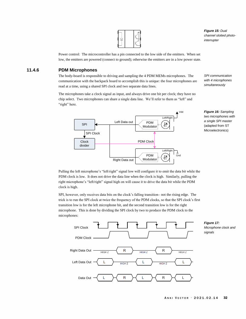
A N K I V E C T O R · 2 0 2 1 . 0 2 . 1 4 32
Power control: The microcontroller has a pin connected to the low side of the emitters. When set
low, the emitters are powered (connect to ground); otherwise the emitters are in a low power state.
11.4.6 PDM Microphones
The body-board is responsible to driving and sampling the 4 PDM MEMs microphones. The
communication with the backpack board to accomplish this is unique: the four microphones are
read at a time, using a shared SPI clock and two separate data lines.
The microphones take a clock signal as input, and always drive one bit per clock; they have no
chip select. Two microphones can share a single data line. We’ll refer to them as “left” and
“right” here.
Vdd
PDM
Modulator
Left/Right
Left Data out
Right Data out
PDM
Modulator
Left/Right
Gnd
PDM Clock
SPI
Clock
divider
SPI Clock
Pulling the left microphone’s “left/right” signal low will configure it to emit the data bit while the
PDM clock is low. It does not drive the data line when the clock is high. Similarly, pulling the
right microphone’s “left/right” signal high on will cause it to drive the data bit while the PDM
clock is high.
SPI, however, only receives data bits on the clock’s falling transition– not the rising edge. The
trick is to run the SPI clock at twice the frequency of the PDM clocks, so that the SPI clock’s first
transition low is for the left microphone bit, and the second transition low is for the right
microphone. This is done by dividing the SPI clock by two to produce the PDM clock to the
microphones:
PDM Clock
Right Data Out
Left Data Out
Data Out
SPI Clock
Figure 15: Dual
channel slotted photo-
interrupter
SPI communication
with 4 microphones
simultaneously
Figure 16: Sampling
two microphones with
a single SPI master
(adapted from ST
Microelectronics)
Figure 17:
Microphone clock and
signals

A N K I V E C T O R · 2 0 2 1 . 0 2 . 1 4 33
The received data bits (in each byte) will alternate between the left and right microphones, and will
need to be separated and converted by firmware. The SPI peripheral along with a DMA can be
configured to clock in large batches of bytes into a buffer for further processing.
Dividing the clock by two can be performed by a timer built into the STM32. The SPI clock signal
is connected to the input of an STM32 timer (TIMxCHIN). The timer is configured to use an external
input clock source, and generate an output after a divide by two. The output of the timer
(TIMxCHOUT) can then be used as the clock for the PDM microphones.
The clock rates have a limited range on the body board. PDM MEMS microphones clock rates
must be in the range 1 MHz to 3.25MHz. (The products are pretty consistent about this range.)
The SPI clock rate is 2x that PDM’s clock, so the SPI clock rate must be in the range of 2MHz to
6.5MHz. The ST processor’s clock is 48MHz, and its SPI clock must be this frequency divided by
a power of two. This means there are only two possibilities: A 32:1 divider gives an SPI clock
frequency of 6 MHz, and A 16:1 divider gives a clock rate of 3 MHz.
This approach can be extended to sample all four microphones, by coordinating with a second SPI
peripheral:
Vdd
PDM
Modulator
Left/Right
Left Data out
Right Data out
PDM
Modulator
Left/Right
Gnd
PDM Clock
SPI1
Clock
divider
SPI Clock
Vdd
PDM
Modulator
Left/Right
Left Data out
Right Data out
PDM
Modulator
Left/Right
Gnd
PDM Clock
SPI2
11.5. OUTPUTS
11.5.1 Light control
An earlier section (see section 10.3.1 The LED controls) described how the 74AHC164 receives its
GPIO settings from a serial interface, and uses these to illuminate the LED segments within 4 RGB
LEDs.
DataSTM32F030
Clock
74AHC164 4 RGB
LEDs
4 RGB
LEDs
4 RGB
LEDs
Figure 18: Sampling
four microphones with
two SPI masters
(adapted from ST
Microelectronics)
Figure 19: SPI-like
interface to the
74AHC164 and RGB
LEDs

A N K I V E C T O R · 2 0 2 1 . 0 2 . 1 4 34
The 74AHC164 does not share a clock or data line with the PDM’s microphones. The data and
clock are bit-banged – the firmware manually raises and lowers the clock and data lines to send the
data.
Note: care must be taken so that an extra clock edge isn’t received by the 74AHC164. (For
instance, during body board initialization.) There is no synchronization to indicate the first bit of
the 8 bits sent to the 74AHC164.
11.5.2 Motor Driver and control
Each motor driver is an H-bridge, allowing a brushed-DC motor to turn in either direction.
Each side of the H-bridge based on the DMC2038LVT, which has a P-FET and N-FET in each
package. Two of these are needed for each motor.
The MCU (probably) independently controls the high side and low side to prevent shoot thru. This
is done by delaying a period of time between turning off a FET and turning on a FET. The
microcontroller drives the PFET by using its GPIO output in open-collector/open-drain
configuration: it turns the FET on by pulling gate low, and lets a resistor pull the gate high (to
battery supply) to turn the FET off.
The motors can be controlled with a control loop that takes feedback from the optical encoder to
represent speed and position. The firmware must take care to prevent burn out if they have been
stalled at full power for 15 seconds or more.
11.6. COMMUNICATION
The communication protocols are described in Chapter 12.
11.7. COMMUNICATION WITH THE HEAD-BOARD
The body-board communicates with the head-board via RS-232 3.3V (3 Mbits/sec13). As the MCU
does not have a crystal, there may be communication issues from clock drift at extreme
temperatures; since Vector is intended for use at room temperature, the effect may be negligible.
The body-board does something clever to communicate at such a high rate, while supporting the
other functions. The issue is that the microcontroller does not have enough DMA resources for the
UART and the SPI channels. The DMA has fixed channels to support the SPI receive, but this is
13 Value from analyzing the firmware, RAMPOST and vic-switchboard programs. Melanie T measured it on an oscilloscope and estimated it to be 2Mbps.
Figure 20: Motor
driver H-bridge

A N K I V E C T O R · 2 0 2 1 . 0 2 . 1 4 35
the same as the channel available for the UART TX. But there are two remaining DMA channels
available for the UART RX function.
To send data to the head board, the firmware retasks one of these DMA channels. The DMA
peripheral doesn’t care which address it sends to or receives from; nor does it enforce direction.
What it means to be a “UART RX” channel is that it looks at the high bits of the address of the
peripheral it is connected to – the UART in this case – and uses that to transfer each byte when a
“received byte” event is received from the UART. The firmware configures the DMA channel to
transfer a byte to the UART TX channel… and the DMA will transfer a byte only when the UART
receives a byte. To ensure that a byte is received, a weak resistor is connected from the TX to the
RX line so that the UART is receiving each byte it sends, triggering the next byte to be sent.
The firmware can be updated over the serial communication by the head-board.
11.7.1 Communication with manufacturing test station
The body-board communicates with the test station using a RS-232 1.8V (115.2 Kbits/sec14) half-
duplex protocol. The communication pin is also used for measuring the charger input voltage.
The firmware can be updated over the serial communication by the head-board.
Note: this communication is only implemented in DVT firmware; it is not implemented in
production firmware.
12. REFERENCES & RESOURCES
Amitabha, Benchmarking the battery voltage drain in Anki Vector and Cozmo, 2018 Dec 31
https://medium.com/programming-robots/benchmarking-the-battery-voltage-drain-in-anki-
vector-and-cozmo-239f23871bf8
Diodes, Inc, 74AGC164 8-Bit Parallel-Out Serial Shift Registers, Rev 2, 2015 Aug
https://www.diodes.com/assets/Datasheets/74AHC164.pdf
Diodes Inc, DMG2305UX P-Channel Enhancement Mode MOSFET
https://www.diodes.com/assets/Datasheets/DMG2305UX.pdf
Diodes, Inc, DMC2038LVT Complementary Pair Enhancement Mode MOSFET
https://www.diodes.com/assets/Datasheets/products_inactive_data/DMC2038LVT.pdf
Entinger, Alexander; Anki Vector base-board connector
https://github.com/aentinger/anki-vector-baseboard
Everlight EAAPMST3923A2
Monolithic Power, MP2617A, MP2617B 3A Switching Charger with NVDC Power Path
Management for Single Cell Li+ Battery, Rev 1.22 2017 Jun 29
https://www.monolithicpower.com/pub/media/document/MP2617A_MP2617B_r1.22.pdf
Panda, a data sheet for a similar single-cell lithium battery
https://panda-bg.com/datasheet/2408-363215-Battery-Cell-37V-320-mAh-Li-Po-303040.pdf
Sharp GP1S092HCPIF Compact Transmissive Photointerrupter, 2005 Oct 3
https://datasheet.lcsc.com/szlcsc/Sharp-Microelectronics-GP1S092HCPIF_C69422.pdf
ST Microelectronics, STM32F030x8, Rev 4, 2019-Jan
https://www.st.com/resource/en/datasheet/stm32f030c8.pdf
ST Microelectronics. AN5027 Application Note: Interfacing PDM digital microphones using
STM32 MCUs and MPUs, Rev 2, 2019 July
https://www.st.com/resource/en/application_note/dm00380469-interfacing-pdm-digital-
microphones-using-stm32-mcus-and-mpus-stmicroelectronics.pdf
14 Value from analyzing the firmware.

A N K I V E C T O R · 2 0 2 1 . 0 2 . 1 4 36
ST Microelectronics. Touch sensing
https://www.st.com/content/ccc/resource/technical/document/application_note/group0/ed/0d/4
d/87/04/1d/45/e5/DM00445657/files/DM00445657.pdf/jcr:content/translations/en.DM004456
57.pdf
https://www.st.com/en/embedded-software/32f0-touch-lib.html
https://hsel.co.uk/2016/05/22/stm32f0-software-capacitive-touch/
https://github.com/pyrohaz/STM32F0-SoftTouch
ST Microelectronics. Tutorial for MEMS microphones, Rev2, 2017 Feb
https://www.st.com/resource/en/application_note/dm00103199-tutorial-for-mems-
microphones-stmicroelectronics.pdf
ST Microelectronics. VL53L0X World’s smallest Time-of-Flight ranging and gesture detection
sensor, Rev 2, 2018 Apr
https://www.st.com/en/imaging-and-photonics-solutions/vl53l0x.html
https://www.st.com/resource/en/datasheet/vl53l0x.pdf

A N K I V E C T O R · 2 0 2 1 . 0 2 . 1 4 37
CHAPTER 5
Accessory Electronics
Design Description
This chapter describes the electronic design of the Anki Vector accessories:
The charging station
The habitat (Vector space)
The companion cube
13. CHARGING STATION
The charging station is intended to provide energy to Vector, allowing him to recharge.
Home symbol that Vector
can identify
USB power
cord
Visual path for Vector to
follow
Terminals to charge
Vector
The charging station has a USB cable that plugs into an outlet adapter or battery. The adapter or
battery supplies power to the charging station. The base of the station has two terminals to supply
+5V (from the power adapter) to Vector, allowing him to recharge. The terminals are offset in
such a way to prevent Vector from accidentally being subject to the wrong polarity. Vector has to
be backed into charging station in mate with the connectors. Vector face-first, even with his arms
lifted, will not contact the terminals.
The charging station has an optical marker used by Vector to identify the charging station and its
pose (see chapter 21).
USB
Connector
Charging
Terminals
Figure 21: Charging
station main features
Figure 22: Charging
station block diagram
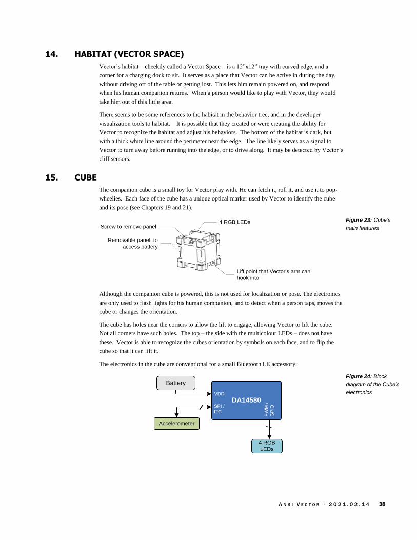
A N K I V E C T O R · 2 0 2 1 . 0 2 . 1 4 38
14. HABITAT (VECTOR SPACE)
Vector’s habitat – cheekily called a Vector Space – is a 12”x12” tray with curved edge, and a
corner for a charging dock to sit. It serves as a place that Vector can be active in during the day,
without driving off of the table or getting lost. This lets him remain powered on, and respond
when his human companion returns. When a person would like to play with Vector, they would
take him out of this little area.
There seems to be some references to the habitat in the behavior tree, and in the developer
visualization tools to habitat. It is possible that they created or were creating the ability for
Vector to recognize the habitat and adjust his behaviors. The bottom of the habitat is dark, but
with a thick white line around the perimeter near the edge. The line likely serves as a signal to
Vector to turn away before running into the edge, or to drive along. It may be detected by Vector’s
cliff sensors.
15. CUBE
The companion cube is a small toy for Vector play with. He can fetch it, roll it, and use it to pop-
wheelies. Each face of the cube has a unique optical marker used by Vector to identify the cube
and its pose (see Chapters 19 and 21).
4 RGB LEDsScrew to remove panel
Lift point that Vector’s arm can
hook into
Removable panel, to
access battery
Although the companion cube is powered, this is not used for localization or pose. The electronics
are only used to flash lights for his human companion, and to detect when a person taps, moves the
cube or changes the orientation.
The cube has holes near the corners to allow the lift to engage, allowing Vector to lift the cube.
Not all corners have such holes. The top – the side with the multicolour LEDs – does not have
these. Vector is able to recognize the cubes orientation by symbols on each face, and to flip the
cube so that it can lift it.
The electronics in the cube are conventional for a small Bluetooth LE accessory:
Battery
4 RGB
LEDs
Accelerometer
DA14580SPI /
I2C
VDD
PW
M /
GP
IO
Figure 23: Cube’s
main features
Figure 24: Block
diagram of the Cube’s
electronics

A N K I V E C T O R · 2 0 2 1 . 0 2 . 1 4 39
The Cube’s electronic design includes the following elements:
Element Description
accelerometer The accelerometer is used to detect movement and taps of the cube.
battery The cube is powered by a 1.5 volt N / E90 / LR1 battery cell.15
crystal The crystal provides the accurate frequency reference used by the Bluetooth LE radio.
Dialog DA14580 This is the Bluetooth LE module (transmitter/receiver, as well as microcontroller and protocol
implementation).
RGB LEDs There are 4 RGB LEDs. They can flash and blink. Unlike the backpack LEDs, two LEDs can
have independent colors.
The communication protocol is described in Chapter 14, and the GUIDs for the services and
characteristics are given in Appendix G.
15.1. OVER THE AIR APPLICATION FIRMWARE DOWNLOAD
The DA14580 has a minimal ROM boot loader that initializes hardware, moves a secondary boot
loader from “One Time Programmable” ROM (OTP) into SRAM, before passing control to it. The
firmware is executed from SRAM to reduce power consumption. The secondary boot-loader is
passed the application firmware from Vector over Bluetooth LE. This application is loaded into
SRAM and passed control.
15.2. REFERENCES & RESOURCES
Dialog, SmartBond™ DA14580 and DA14583
https://www.dialog-semiconductor.com/products/connectivity/bluetooth-low-
energy/smartbond-da14580-and-da14583
Dialog, DA14580 Low Power Bluetooth Smart SoC, v3.1, 2015 Jan 29
Dialog, UM-B-012 User manual DA14580/581/583 Creation of a secondary bootloader,
CFR0012-00 Rev 2, 2016 Aug 24
https://www.dialog-semiconductor.com/sites/default/files/um-b-
012_da14580_581_583_creation_of_a_secondary_boot_loader_v3.2.pdf
Dialog, Application note: DA1458x using SUOTA, AN-B-10, Rev 1, 2016-Dec-2
https://www.dialog-semiconductor.com/sites/default/files/an-b-
010_da14580_using_suota_0.pdf
15 The size is similar to the A23 battery, which will damage the cube’s electronics.
Table 8: The Cube’s
electronic design
elements

A N K I V E C T O R · 2 0 2 1 . 0 2 . 1 4 40
[This page is intentionally left blank for purposes of double-sided printing]

A N K I V E C T O R · 2 0 2 1 . 0 2 . 1 4 41
PART II
Basic Operation
This part provides an overview of Vector’s software design.
THE SOFTWARE ARCHITECTURE. A detailed look at Vector’s overall software architecture and
main modules.
STARTUP. A detailed look at Vector’s startup and shutdown processes
POWER MANAGEMENT. A detailed look at Vector’s architecture for battery monitoring,
changing and other power management.
BASIC INPUT AND OUTPUT. A look at push button, touch sensing, surface proximity sensors,
time of flight proximity sensing, and backpack LEDs.
INERTIAL MOTION SENSING

A N K I V E C T O R · 2 0 2 1 . 0 2 . 1 4 42
[This page is intentionally left blank for purposes of double-sided printing]
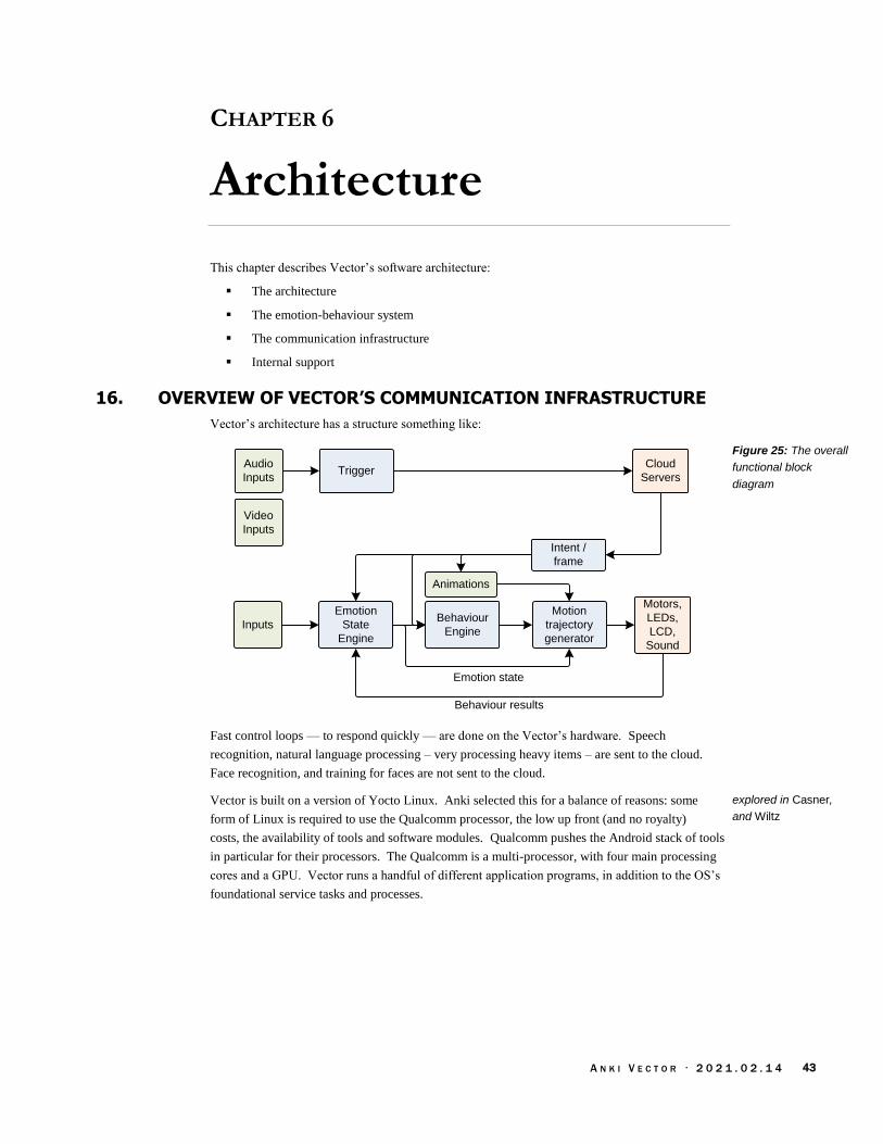
A N K I V E C T O R · 2 0 2 1 . 0 2 . 1 4 43
CHAPTER 6
Architecture
This chapter describes Vector’s software architecture:
The architecture
The emotion-behaviour system
The communication infrastructure
Internal support
16. OVERVIEW OF VECTOR’S COMMUNICATION INFRASTRUCTURE
Vector’s architecture has a structure something like:
Inputs
Emotion
State
Engine
Behaviour
Engine
Behaviour results
Motors,
LEDs,
LCD,
Sound
Motion
trajectory
generator
Emotion state
Animations
Audio
InputsTrigger
Cloud
Servers
Intent /
frame
Video
Inputs
Fast control loops — to respond quickly — are done on the Vector’s hardware. Speech
recognition, natural language processing – very processing heavy items – are sent to the cloud.
Face recognition, and training for faces are not sent to the cloud.
Vector is built on a version of Yocto Linux. Anki selected this for a balance of reasons: some
form of Linux is required to use the Qualcomm processor, the low up front (and no royalty)
costs, the availability of tools and software modules. Qualcomm pushes the Android stack of tools
in particular for their processors. The Qualcomm is a multi-processor, with four main processing
cores and a GPU. Vector runs a handful of different application programs, in addition to the OS’s
foundational service tasks and processes.
Figure 25: The overall
functional block
diagram
explored in Casner,
and Wiltz
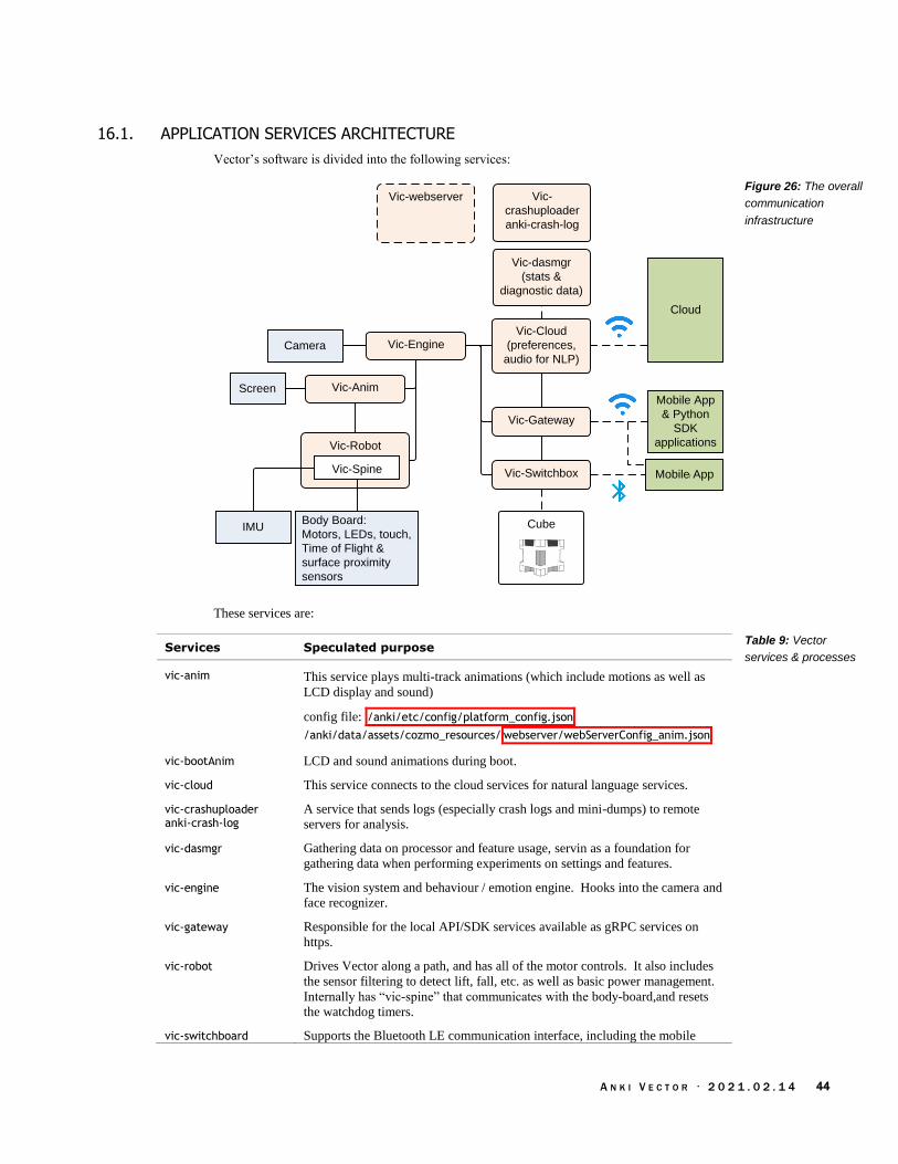
A N K I V E C T O R · 2 0 2 1 . 0 2 . 1 4 44
16.1. APPLICATION SERVICES ARCHITECTURE
Vector’s software is divided into the following services:
Vic-Robot
Body Board:
Motors, LEDs, touch,
Time of Flight &
surface proximity
sensors
Vic-dasmgr
(stats &
diagnostic data)
Mobile App
Cloud
ScreenMobile App
& Python
SDK
applications
Cube
Camera
Vic-Spine
Vic-Cloud
(preferences,
audio for NLP)
Vic-Anim
IMU
Vic-Engine
Vic-Gateway
Vic-Switchbox
Vic-
crashuploader
anki-crash-log
Vic-webserver
These services are:
Services Speculated purpose
vic-anim This service plays multi-track animations (which include motions as well as
LCD display and sound)
config file: /anki/etc/config/platform_config.json
/anki/data/assets/cozmo_resources/ webserver/webServerConfig_anim.json
vic-bootAnim LCD and sound animations during boot.
vic-cloud This service connects to the cloud services for natural language services.
vic-crashuploader anki-crash-log
A service that sends logs (especially crash logs and mini-dumps) to remote
servers for analysis.
vic-dasmgr Gathering data on processor and feature usage, servin as a foundation for
gathering data when performing experiments on settings and features.
vic-engine The vision system and behaviour / emotion engine. Hooks into the camera and
face recognizer.
vic-gateway Responsible for the local API/SDK services available as gRPC services on
https.
vic-robot Drives Vector along a path, and has all of the motor controls. It also includes
the sensor filtering to detect lift, fall, etc. as well as basic power management.
Internally has “vic-spine” that communicates with the body-board,and resets
the watchdog timers.
vic-switchboard Supports the Bluetooth LE communication interface, including the mobile
Figure 26: The overall
communication
infrastructure
Table 9: Vector
services & processes

A N K I V E C T O R · 2 0 2 1 . 0 2 . 1 4 45
application protocol (see Chapter 13). Routes messages between the other
services? Manages the access keys
vic–webserver A developer-only tool that aids in visualizing the internal state of the software.
Within the each vic- server processes, there are one or more event-driven communication threads.
A thread likely has the following basic structure:
Thread
Process event /
message
Block
Input
Messages
Message /
event
Dequeue
Message
Call
ThreadOutput
Messages
The communication threads have an input message queue. On Vector these include
A socket, between processes
A serial interface with the body board
A web-socket
Other, inter-thread message queue
The communication thread blocks on one or more message queue events. It wakes when there is
an incoming event/message, or there has been an error or timeout while waiting. When it wakes, it
dequeues the message, takes action and goes back to waiting. It may post messages (or other
signals) to other threads, possibly indirectly as a result of framework/library/system calls.
Within a server process, convenient C++ data structures are used. The vic- servers also use CLAD,
and JSON data structures, and include many helper procedures to convert between the two. It
appears that a process interprets and generates a JSON data structure. To communicate with
another process, it converts the JSON to a CLAD (since it is a contiguous span of bytes), sends that
to the other process; the other process reverses the process, converting it JSON and using that
interpret the message.
Figure 27: Basic
communication thread
structure

A N K I V E C T O R · 2 0 2 1 . 0 2 . 1 4 46
16.2. EMOTION MODEL, BEHAVIOUR ENGINE, ACTIONS AND ANIMATION ENGINE
Vector’s high-level AI is organized around an emotion model, and a behaviour engine that drives
goals, responses and other actions.
Emotion
State
Engine
· Lift motors, Head angle,
· Driving
· Procedural Face
· Visual Animations
· Backpack LEDs
· Sound
Emotion state
Behaviour
Engine
Animation trigger
Select
animation
based on
mood
Animation
Animation
Engine
There are many similar terms used within Vector’s AI model, but there are subtle distinctions
between them:
· An AI Feature is the high level behaviors as a person would experience. There are about
70 of these. Note the name shouldn’t be confused with a feature flag or feature toggle;
that is a different concept, for software elements that are not ready yet, but included in the
code base.
· A behavior is “a complex task [that] may include combinations of animation, path
planning or other functionality. Examples include” driving to the charger, set the lift
height, etc. An AI Feature takes at least one behavior to carry out; it often takes many.
The current emotional state can influence which behavior is selected, and affect how it is
carried out. Intents (response to voice interaction) can initiate behaviors. Behaviors can
initiate actions.
· An action is like a mini-behavior, with some differences. Multiple actions can run at a
time – so long as they don’t use the same resources– but only one behavior can run at a
time. Actions can wait in a queue.
· An animation is a scripted motion, sound, light pattern, and/or facial animation (or picture
on the display) that Vector carries out. Behaviors and actions can initiate animations. The
animation engine selects the specific animation, from a pool of alternatives, based on
context and current emotional state. An animation can’t use the sensors, so it can’t adapt
to the environmental conditions. For instance, to drive up to a hand (or a cube) requires the
time of flight sensor; so an action is required.
Anki Vector SDK
Figure 28: The
behaviour-animation
flow
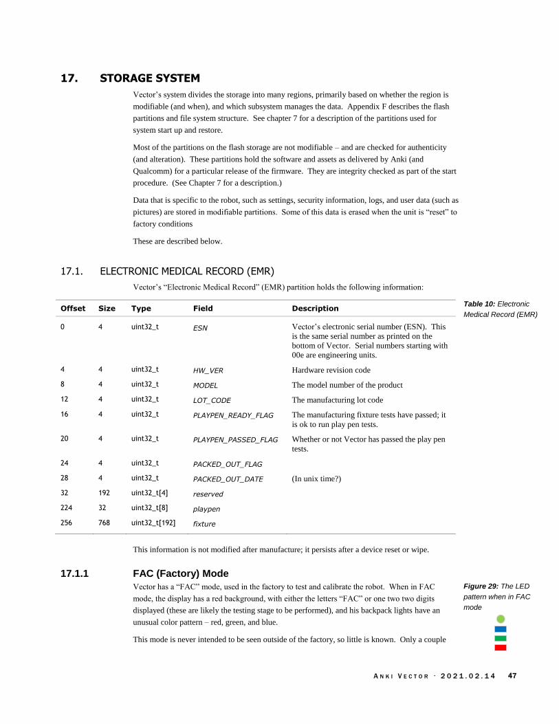
A N K I V E C T O R · 2 0 2 1 . 0 2 . 1 4 47
17. STORAGE SYSTEM
Vector’s system divides the storage into many regions, primarily based on whether the region is
modifiable (and when), and which subsystem manages the data. Appendix F describes the flash
partitions and file system structure. See chapter 7 for a description of the partitions used for
system start up and restore.
Most of the partitions on the flash storage are not modifiable – and are checked for authenticity
(and alteration). These partitions hold the software and assets as delivered by Anki (and
Qualcomm) for a particular release of the firmware. They are integrity checked as part of the start
procedure. (See Chapter 7 for a description.)
Data that is specific to the robot, such as settings, security information, logs, and user data (such as
pictures) are stored in modifiable partitions. Some of this data is erased when the unit is “reset” to
factory conditions
These are described below.
17.1. ELECTRONIC MEDICAL RECORD (EMR)
Vector’s “Electronic Medical Record” (EMR) partition holds the following information:
Offset Size Type Field Description
0 4 uint32_t ESN Vector’s electronic serial number (ESN). This
is the same serial number as printed on the
bottom of Vector. Serial numbers starting with
00e are engineering units.
4 4 uint32_t HW_VER Hardware revision code
8 4 uint32_t MODEL The model number of the product
12 4 uint32_t LOT_CODE The manufacturing lot code
16 4 uint32_t PLAYPEN_READY_FLAG The manufacturing fixture tests have passed; it
is ok to run play pen tests.
20 4 uint32_t PLAYPEN_PASSED_FLAG Whether or not Vector has passed the play pen
tests.
24 4 uint32_t PACKED_OUT_FLAG
28 4 uint32_t PACKED_OUT_DATE (In unix time?)
32 192 uint32_t[4] reserved
224 32 uint32_t[8] playpen
256 768 uint32_t[192] fixture
This information is not modified after manufacture; it persists after a device reset or wipe.
17.1.1 FAC (Factory) Mode
Vector has a “FAC” mode, used in the factory to test and calibrate the robot. When in FAC
mode, the display has a red background, with either the letters “FAC” or one two two digits
displayed (these are likely the testing stage to be performed), and his backpack lights have an
unusual color pattern – red, green, and blue.
This mode is never intended to be seen outside of the factory, so little is known. Only a couple
Table 10: Electronic
Medical Record (EMR)
Figure 29: The LED
pattern when in FAC
mode

A N K I V E C T O R · 2 0 2 1 . 0 2 . 1 4 48
of units have been found in this mode; one after it had been intentionally damaged, and its
calibration & EMR data were corrupted or inaccessible.16 In all likelihood, the software checks its
EMR to see if it has been released; if not, it enters the FAC mode at whatever the “next” stage is
according to the EMR. At that point Vector expects to be placed into manufacturing test fixtures,
such as the playpen.
17.1.2 Manufacturing Lot Codes
A manufacturing lot code is an identifier that used to track the components, and robot
subassemblies that were used in robots, as well as the date they were made. “If there's a problem
in a particular batch of components (or maybe the people working at the factory that day), we can
identify which robots were affected.”
“A lot code is 4 numbers. A typical lot code is 2 18 36 201.
“2 is the factory. All Vectors were made at factory 2.”
18 is the last two digits of the year, 2018.
“36 means week 36 of 2018 - that's first week of September.
“201 means ‘Standard Edition Vector, US-only version’”
The robots were made “in big batches in July/August, and they didn't start coming back [to
customer service] until January/February,” when Anki would “put the fixes into the next big batch
the upcoming year.”
17.1.3 Playpen Data
The playpen is a testing area with ramps, barriers, camera targets at a variety of angles, cube and a
charging station. Vector is put into one during manufacture to check his sensors, camera
calibration, motor function, microphone and a check over his overall functions. The playpen tests
involve many checks to ensure that his head is assembled and attached correctly, as wells that his
lower body is assembled correctly. These use almost of all of his functions: that he can correctly
navigate, detect cliffs, see and count dots, see markers (getting their type and size correct), dock,
and charge.
The images that Vector sees during these tests are kept with unit. This way, if the unit is returned
later with a vision-related problem, the images from the manufacturing are there to see if, as part of
the manufacturing record for analysis of returned products, “we can go back to those images and
see if it's a new problem or was always there.”
There is also a sound booth that checked that his speaker was working properly and did not exceed
limits.
16 https://forums.anki.com/t/any-one-know-what-error-code-50-is/40891

A N K I V E C T O R · 2 0 2 1 . 0 2 . 1 4 49
17.2. OEM PARTITION FOR OWNER CERTIFICATES AND LOGS
The OEM partition is a read/writeable ext2 file-system. It is used to hold information from the
robots testing at the factory, and its cloud access certificates:
Folder Description
The top level holds the log files.
cloud Holds the SDK TLS certificate and signing keys. With newer
firmware, the folder may also hold some other calibration
information.
nvStorage Holds some binary “.nvdata” files
18. SECURITY AND PRIVACY
Vector’s design includes a well thought-out system to protect against disclosing (i.e. providing to
strangers) sensitive information, and allowing the operator to review and delete it at any time:
Photographs taken by Vector are not sent to (nor stored in) a remote server. They are
stored in encrypted file system, and only provided to authenticated applications on the
local network. Each photograph can be individually deleted (via the mobile application).
The image stream from Vector’s camera is not sent to a remote server. It is only provided
to authenticated applications on the local network.
The data used to recognize faces17 and the names that Vector knows are not sent to (nor
stored in) a remote server. The information is stored in an encrypted file system. The list
of known faces (and their names) is only provided to authenticated applications on the
local network. Any facial recognition data not associated with a name is deleted when
Vector goes to sleep. Facial data associated with an individual name can be deleted (along
with the name) via the mobile application.
“[After] you say the wake words, “Hey Vector”, Vector streams your voice command to
the cloud, where it is processed. Voice command audio is deleted after processing. Text
translations of commands are saved for product improvement not associated with a user.”
The audio stream from the microphone — if it had been finished being implemented –
would have been provided to authenticated applications on the local network.
Information about the owner can be erased using the Clear User Data menu option.
Control of the robots movement, speech & sound, display, etc. is limited to authenticated
applications on the local network.
Vector’s software is protected from being altered in a way that would impair its ability to secure
the above. At the high level, this is done by requiring signed software files, and a signed file
system that is checked for alteration. The protections extend all the way to low-level electronics,
where the JTAG access fuses are blown, so that extracting or modifying RAM, flash or other data
can not be done. (Anki did this as a matter of standard operating procedure on all electronic
products.)
17 The Anki privacy and security documents logically imply that the face image is not sent to Anki servers to construct a recognition pattern. There are no communication structures to send images to the cloud.
Table 11: OEM
partition file hierarchy
Anki Security &
Privacy Policy

A N K I V E C T O R · 2 0 2 1 . 0 2 . 1 4 50
Vector also indicates when it is doing something sensitive:
When the microphone is actively listening, it is always indicated on the backpack lights
(blue).
The microphone is enabled by default, but only listening for the wake word, unless
Vector’s microphone has been disabled.
When the camera is taking a picture (to be saved), Vector makes a sound.
When the camera is on?
Unless the backpack lights are all orange, the WiFi is enabled. (All orange indicates it is
disabled.)
18.1. ENCRYPTED COMMUNICATION
The personally identifying information and other data about the owner — photos, account
information, WiFi passwords, and so one — is only sent on encrypted channels.
18.2. ENCRYPTED FILESYSTEM
The file system with the user’s data — photos, account information, WiFi passwords, and so one
— is encrypted. The encryption key is unique to each robot and not shared elsewhere.
18.3. THE OPERATING SYSTEM
There is a chain of firmware signed by Qualcomm and Anki. This is intended to protect Vector’s
software from being altered in a way that would impair its ability to secure the information above.
Android boot loaders typically include a few powerful (but unchecked) bits that disable the
signature checking, and other security features. These bits typically are set either thru commands
to the firmware during boot up, by applications, or possibly by hack/exploit. Sometimes this
requires disassembling the device and shorting some pins on the circuit board.
Vector doesn't support those bits, nor those commands. Signature checking of the boot loader,
kernel and RAM disk can't be turned off.
18.3.1 The possibility for future modifications to Vector’s software
Anki created special Vectors for internal development. The software for these units has a special
version of the kernel and RAM disk that does not check system room file system, and makes it
writable. This file system has Vector’s application software, supports SSH. This software was
tightly controlled, and “only .,. available inside the Anki corporate network.” For purposes of
customizing and updating Vector, this version is essential. (Note: the kernel and RAM disk can’t
be modified.)
Note: the OTA software has a “dev” (or development) set of OTA packages. Those packages are
not the same; they are essential software release candidates being pushed out for test purposes.
Jane Fraser, 2019

A N K I V E C T O R · 2 0 2 1 . 0 2 . 1 4 51
18.4. AUTHENTICATION
The web services built into Vector require a token. This is used to prove that you have
authenticated (with the more capable — and not physically accessible — servers). This
authentication is to protect:
Photos already on Vector
The image stream from the camera
The audio stream from the microphone — if it had finished being implemented
The sensitive owner information
Controlling the robot
(That is to say, to prevent disclosure)
19. CONFIGURATION AND ASSET FILES
Vector’s software is configured by JSON files. Some of the JSON files were probably created by
a person (for the trivial ones). Others were created by scripting / development tools; a few of these
were edited by developers. These JSON files are clearly intended to be edited by people:
The files are cleanly spaced, not in the most compact minimized size
The JSON parser supports comments, which is not valid JSON. Many files have
comments in them. Many have sections of the configuration that are commented out.
19.1. CONFIGURATION FILES
The top-level configuration file provides the paths to the network other configuration files. It is
found at:
/anki/etc/config/platform_config.json
This path is hardcoded into the vic-dasmgr, and provided in the editable startup files for vic-anim
and vic-engine. The configuration file contains a JSON structure with the following fields:
Field Value Description & Notes
DataPlatformCachePath “/data/data/com.anki.victor/cache” This folder is used to hold logs and
diagnostic information until it can be
sent to the cloud servers.
DataPlatformPersistentPath “/data/data/com.anki.victor/persistent” This folder holds the settings for the
Vector application software.
DataPlatformResourcesPath “/anki/data/assets/cozmo_resources” The path to most configuration files and
assets
When describing the configuration and asset files, a full path will be provided. When the path is
constructed from different parts, the part that is specified in another configuration or binary file
will be outlined. The path to a settings file might look like:
/anki/assets/cozmo_resources/ config/engine/settings_config.json
The path leading up to the settings file (not outlined in red) is specified in an earlier configuration
file, usually the platform configuration file described above.
Table 12: The
platform config JSON
structure

A N K I V E C T O R · 2 0 2 1 . 0 2 . 1 4 52
20. SOFTWARE-HARDWARE LAYERS
Body-board input/output software architecture
The LCD display
Camera
20.1. THE BODY BOARD INPUT/OUTPUT
The body-board input-output software has a structure like so:
SPI
RGB LEDs
UART
Analog In
Touch
Battery
Debounce
Button MotorMotorMotors
Body
board
Charger
Motor
Controllers
Motor
Controllers
Motor
Controllers
MotorMotorEncoders
Thermistor
Battery
Disconnect
Digital
InputDigital
OutputI2C
Time of
Flight
MotorMotorMicrophones
Vic-anim
Vic-robot
20.2. THE LCD DISPLAY
Four different applications may access the display, albeit not at the same time:
LCD displayFrame buffer
/dev/fb0 SPI
vic-
bootAnimvic-anim
displayFault
Code
vic-
faultDisplayCode
Note: displayFaultCode is present on Vector, but it is not called by any program.
The LCD is connected to the MPU via an SPI interface (/dev/spidev1.0). The frame buffer
(/dev/fb0) is essentially a buffer with metadata about its width, height, pixel format, and
orientation. Application modifies the frame buffer by write() or memmap() and modifies the bytes.
Then the frame buffer has the bytes transfer (via SPI) tot the display.
vic-anim employs a clever screen compositing system to create Vector’s face (his eyes), animate
text jumping and exploding, and small videos, such as rain or fireworks.
The vic-faultDisplayCode and Customer Care Information Screen of vic-anim have a visual
aesthetic is unlike the rest of Vector. These modes employ a barebones system for the display.
Figure 30: The body
board-related
architecture
Figure 31: The LCD
architecture

A N K I V E C T O R · 2 0 2 1 . 0 2 . 1 4 53
The text appears to rendered into the buffer using OpenCV’s putText() procedure, and transferring
it to the display without any further compositing.
Not sure if the transfer is in a driver, in the kernel, or in user space... or which process would have
it in user space.
20.3. THE CAMERA
The camera subsystem has the following architecture:
dev/socket/vic-engine-cam_client0
mm-anki-camera
Python SDK
applicationsVic-Gateway
Vic-enginelibcozmo_engine
libcameraService
CameraMIPI
IMU
Vertical sync
The camera’s vertical synchronization signal is connect to the interrupt line on IMU, triggering
accelerometer and gyroscope sampling in sync with the camera frame. The vision is used as a
navigation aid, along with the IMU data. The two sources of information are fused together in
the navigation system (see chapter 19) to form a more accurate position and relative movement
measure. The image must be closely matched in time with the IMU samples. However the
transfer of the image from the camera to the processor, then thru several services to vic-engine
introduces variable or unpredictable delays. The camera’s vertical sync – an indication of when
the image is started being sampled – is used to trigger the IMU to take a sample at the same time.
The camera is also used as an ambient light sensor when Vector is in low power mode (e.g.
napping, or sleeping). In low power mode, the camera is suspended and not acquiring images.
Although in a low power state, it is still powered. The software reads the camera’s auto
exposure/gain settings and uses these as an ambient light sensor. (This allows it to detect when
there is activity and Vector should wake.)
21. REFERENCES & RESOURCES
Anki, Elemental Platform
https://anki.com/en-us/company/elemental-platform.html
Describes, as a marketing brochure, much of Anki’s product network architecture.
Anki, Vector Security & Privacy FAQs, 2018
https://support.anki.com/hc/en-us/articles/360007560234-Vector-Security-Privacy-FAQs
Casner, Daniel, Consumer Robots from Smartphone SoCs, Embedded Systems Conference Boston,
2019 May 15
https://schedule.esc-boston.com//session/consumer-robots-from-smartphone-socs/865645
Stein, Andrew; Kevin Yoon, Richard Alison Chaussee, Bradford Neuman, Kevin M.Karol, US
Patent US2019/01563A1, Custom Motion Trajectories for Robot Animation, Anki, filed 2018
Jul 13, published 2019 Apr 18,
Qualcomm, Snapdragon™ 410E (APQ8016E) r1034.2.1 Linux Embedded Software Release Notes,
LM80-P0337-5, Rev. C, 2018 Apr 10
lm80-p0337-
5_c_snapdragon_410e_apq8016e_r1034.2.1_linux_embedded_software_revc.pdf
Figure 32: The
camera architecture
Daniel Casner, 2019
Embedded Vision
Summit

A N K I V E C T O R · 2 0 2 1 . 0 2 . 1 4 54
Tariq, Talha Securing Autonomous Robots at Scale, 2018 Oct 3
https://www.infosecuritynorthamerica.com/RXUK/RXUK_InfosecurityNorthAmerica/16.05-
16.30_Anki.pdf
Wiltz, Chris, Lessons After the Failure of Anki Robotics, Design News, 2019 May 21
https://www.designnews.com/electronics-test/lessons-after-failure-anki-
robotics/140103493460822

A N K I V E C T O R · 2 0 2 1 . 0 2 . 1 4 55
CHAPTER 7
Startup
This chapter describes Vector’s start up and shutdown processes:
The startup process
The shutdown steps
22. STARTUP
Vector’s startup is based on the Android boot loader and Linux startup.18 These are otherwise not
relevant to Vector, and their documentation is referred to. The boot process gets quite far before
knowing why it booted up or being able to response in complex fashion.
1. The backpack button is pressed, or Vector is placed into the charger. This powers the body
board, and the head-board.
a. The body-board boot loader checks the application for validity, using a private key.
The application is run only if it passes the integrity checks.
2. The body-board displays an animation of the backpack LEDs while turning on.
a. If turned on from a button press and the button is released before the LED segments
are fully lit, the power will go off.
b. If the button is held down – for about 5 seconds – the head-board will have reach a
point in its boot process to direct the body-board to keep the battery switch closed.
c. If held for 15 seconds, the body-board will hold is TX line – the head-boards RX line
– low during the boot process. This tells the system to boot into recovery mode.
3. While the head-board boots, the body-board performs several self tests. These include
checking that the microcontroller can communicate with the 4 cliff (surface proximity)
sensors, and the time of flight sensor.
22.1. QUALCOMM’S PRIMARY AND SECONDARY BOOT-LOADER
Meanwhile, on the head-board:
1. “Qualcomm’s Primary Boot Loader is verified and loaded into [RAM] memory19 from
BootROM, a non-writable storage on the SoC. [The primary boot-loader] is then
executed and brings up a nominal amount of hardware,”
2. The primary boot-loader checks to see if a test point is shorted on the board, the unit will
go into emergency download (EDL) mode. It is known that when F_USB pad on the
head-board is pulled to Vcc, USB is enabled; this may be the relevant pin.
18 An ideal embedded system has a fast (seemingly instant) turn on. Vector’s startup isn’t fast. The steps to check the integrity of the
large flash storage – including checking the security signatures – and the complex processes that Linux provides each contribute to the
noticeable slow turn on time. Checking the signatures is inherently slow, by design. 19 The boot loader is placed into RAM for execution to defeat emulators.
Nolen Johnson
Roee Hay

A N K I V E C T O R · 2 0 2 1 . 0 2 . 1 4 56
3. If the primary-boot loader is not in EDL mode it “then verifies the signature of the next
boot-loader in the chain [the secondary boot-loader], loads it, [and] then executes it.”
The secondary boot-loader is stored in the flash partition SBL.
4. If the secondary boot-loader does not pass checks, the primary boot loader will go into
emergency down load mode.
5. “The next boot-loader(s) in the chain are SBL*/XBL (Qualcomm’s Secondary/eXtensible
Boot Loader). These early boot-loaders bring up core hardware like CPU cores, the MMU,
etc. They are also responsible for bringing up core processes .. [for] TrustZone. The last
purpose of SBL*/XBL is to verify the signature of, load, and execute aboot/ABL [Android
boot loader].”
The TrustZone firmware is signed and verified against the processor’s unique key.
The Android boot-loader (aboot) is stored on the “ABOOT” partition.
The secondary boot-loader also supports the Sahara protocol; it is not known how to
activate it.
Note: The keys for the boot-loaders and TrustZone are generated by Qualcomm, with the root
public key programmed into the hardware fuses before delivery to Anki or other customers.
(This is called the silicon-based hardware key, or SHK.) The signed key pair for the secondary
boot-loader, the TrustZone and for aboot are not necessarily the same signed key pair. They are
unique for each of Qualcomm’s customer. Being fuses, the SHK cannot be modified, even with
physical access. The SHK is only accessible to TrustZone firmware and its trustlets; keystores that
are encrypted and decrypted by the SHK must be to the TrustZone for processing.
22.2. ANDROID BOOT-LOADER (ABOOT)
1. “Aboot brings up most remaining core hardware then in turn normally verifies the signature
of the boot image, reports the verity status to Android Verified boot through dm-verity…
On many devices, Aboot/ABL can be configured to skip cryptographic signature checks and
allow booting any kernel/boot image.”
a. On other Android devices, aboot reads the DEVINFO partition for a structure. It
checks the header of the structure for a magic string (“ANDROID-BOOT!”) and
then uses the values within the structure to indicate whether or not the device is
unlocked, whether verity-mode is enabled or disabled, as well as a few other settings.
By writing a version of this structure to the partition, the device can be placed into
unlock mode.
Vector does not support this method of unlocking.
b. “The build system calculates the SHA256 hash of the raw boot.img and signs the
hash with the user’s private key… It then concatenates this signed hash value at the
end of raw boot.img to generate signed boot.img.”
c. “During bootup, [Aboot20] strips out the raw boot.img and signed hash attached at the
end of the image. [Aboot] calculates the SHA256 hash of the complete raw boot.img
and compares it with the hash provided in the boot.img. If both hashes match, kernel
image is verified successfully.”
2. ABoot can either program the flash with software via boot loader mode, or load a kernel.
The kernel can be flagged to use a recovery RAM disk or mount a regular system.
20 The Qualcomm document speaks directly about Little Kernel; ABoot is based on Little Kernel.
Nolen Johnson
silicon-based
hardware key,
processor fuses
Roee Hay
Qualcomm LM80
P0436

A N K I V E C T O R · 2 0 2 1 . 0 2 . 1 4 57
3. If recovery mode, it will load the kernel and file systems from the RECOVERY partitions.
a. Recovery is entered if the active regular partition cannot be loaded, e.g. doesn’t
exist or fails signature check, or
b. The RX signal from the body-board may be held low when aboot starts,
indicating that the operator has held the button and wishes to initiate recovery
mode.21 If this is the case, “anki.unbrick=1” is prepended to the command line
passed to the kernel.
4. ABoot loads the kernel and RAM file system from the active “BOOT” partition and passes it
command line to perform a check of the boot and RAM file system the signatures.22 The
command line is stored in the header of the boot partition; it is checked as part of the
signature check of the boot partition and RAM file system. If the ABoot is compiled for a
developer robot, it will add an “anki.dev” to the command line.
Many of these elements will be revisited in Chapter 32 where updating aboot, boot, and system
partitions are discussed.
22.3. RECOVERY BOOT
The recovery system is, in part, based on an older version of Vector software.
USER DATA FILE SYSTEM. The recovery system does not use the user data file system. Here’s why:
1. The recovery system is risk averse. It is not updated (due to the risk), and has older
software. This software likely has bugs that could be a path for exploitation. By not using
the user data, the user data is protected against these exploits.
2. The user data may be corrupted, erased or gone. This may be the reason that the system in
recovery mode.
3. The files and formats of the user data, and the TrustZone key blobs may have changed with
newer formats and files. The recovery system might not be able to read them. Or it may
not be able to write something that the regular system can write.
FACTORY FILE SYSTEM. The recovery system normally mounts the factory file system (OEM
partition) in read only mode. It can be put into a “factory mode” (FAC) that remounts this file
system as a modifiable.
22.4. REGULAR SYSTEM BOOT
The boot partition holds the linux kernel, and a small RAM disk to initialize the system. It is
passed parameters on the command line from aboot and from the boot.img. The purpose of the
extra (Anki-specific) command line parameters are:
Field Description
anki.unbrick This is used to trigger a boot into recovery mode.
anki.dev This is set to confirm (to the linux system) that this robot is a development
robot and can run development software systems.
dm= The dm-verity command line used to verify the system file system
21 The body-board may body-board a resets/restarts the head-board so that the bootloader runs again. 22 The check specifies the blocks on the storage to perform a SHA256 check over and provides expected signature result.
Table 13: linux
command line
parameters

A N K I V E C T O R · 2 0 2 1 . 0 2 . 1 4 58
After the kernel has finished loading, it launches init. In Vector, it is a shell script with Anki-
specific system checks:
Launch OS on
main partition
Command
line has
“anki.dev”?
Yes
No
No
Tell RAMPOST
to cut powerSet up dm-verity
Command
line has
“dm=”?
Perform
RAMPOST
check of system
controller
aboot
Exit, halting
head board
Yes
These Anki-specific system steps are:
1. The RAM file system contains primarily of two programs: init and /bin/rampost. init is a
shell script and the first program launched by the kernel. This script turns on the LCD, its
backlight and initiate communication with the body-board. (These occur ~6.7 seconds
after power-on is initiated).
a. rampost initializes the LCD, clearing the display. It also shows a start up screen on
the display of developer units.
b. rampost will perform a firmware upgrade of the body-board if its version is out of
date. It loads the firmware from syscon.dfu (Note: the firmware in the body-board is
referred to as syscon.)
c. rampost checks the battery voltage, temperature and error flags. It posts any issues to
/dev/rampost_error. See Appendix D Table 605: RAMPOST DFU status codes for
DFU related error codes.
d. All messages from rampost are prefixed with “@rampost.”
2. Next, init performs a signature check of the system partition to ensure integrity. This is
triggered by the command line which includes dm-verity options prefixed with “dm=”. If
the system does not pass checks, init fails and exits.
a. Note: none of the file systems in fstab marked for verity checking, so this is the only
place where it is performed.
Figure 33: The linux
boot-partition init-script
flow
A N K I V E C T O R · 2 0 2 1 . 0 2 . 1 4 59
3. The main system file-system is mounted and launches the main system initialization.
The regular boot uses systemd to allow of the startup steps to be performed in parallel. The rough
start up sequence is:
1. Starts the Qualcomm Secure Execution Environment Communicator (dev-qseecom.device)
and ION memory allocator (dev-ion.device)
2. The encrypted user file system is checked and mounted (via the mount-data service). This
file system is where the all of the logs, people’s faces, and other information specific to the
individual Vector are stored. The keys to this file system are stored in a blob within
“switchboard” but are encoded and decoded by a TrustZone key manager (which uses the
processor’s secret key). This file system can only be read by the MPU that created it.
a. If “anki.unbrick” is on the command line, the user data partition is not touched;
instead a temporary file system is created and used instead.23 This flag is not
meaningful in the regular system since the boot-loader will only launch the recovery
partition software with “anki.unbrick”
b. If the data partition is empty (i.e., erased to clear the user data), the user data
partitions is formatted;
3. The MPU’s clock rate is limited to 533Mhz, and the RAM is limited to 400MHz to prevent
overheating.
4. The camera power is enabled
5. If Vector doesn’t have a robot name, Vic-christen is called to give it one.
6. After that several mid-layer communication stacks are started:
a. usb-service any time after that
b. the WiFi connection manager (connman)
c. The time client (chronyd), to retrieve network time. (Vector does not have a clock
that keeps time when turned off)
d. init-debuggerd
7. multi-user, sound, init_post_boot
8. The “Victor Boot Animator” is started (~8 seconds after power on) and shows the sparks
turning into the “V” splash screen on the display.
9. Victor Boot completes ~20.5 after power on, and the post boot services launches
10. The vic-crashuploader service is started to gather crash logs and dump files, some of which
may have been created during a previous boot attempt. These will be uploaded when
internet access is restored.
11. The vic-robot and main robot services are started.
12. Once the startup has sufficiently brought up enough the next set of animations the sound of
boot
23 I’m not sure how this would be useful as is with the regular system software. It seems like Vector could boot up, appear like
everything is wiped, and needs to be re-set up… then some time later, Vector would reboot, and appear to be his previous self – including any misconfiguration that motivated the unbrick the first time.

A N K I V E C T O R · 2 0 2 1 . 0 2 . 1 4 60
13. VicOS is running ~32 seconds after power on. The boot is complete, and Vector is ready
to play
22.5. ABNORMAL SYSTEM BOOT
If there is a problem during startup – such as one of the services is unable to successfully start, a
fault code associated with that service is stored in /run/fault_code and the fault code displayed.
See chapter 33 for a description of the display of fault codes and diagnostics. See Appendix D for
fault codes.
22.6. REGULAR REBOOTS
Vector reboots nightly (if left on) and checks for software updates. See chapter 32 for information.
23. REFERENCES & RESOURCES
Android, Verified Boot
https://source.android.com/security/verifiedboot/
Bhat, Akshay; Secure boot on Snapdragon 410¸TimeSys, 2018 Aug 23
https://www.timesys.com/security/secure-boot-snapdragon-410/
Discusses how one can get the source to the secondary boot-loader (SBL), the tools to sign it
and aboot using sectools
https://gitlab.com/cryptsetup/cryptsetup/wikis/DMVerity
Hay, Roee. fastboot oem vuln: Android Bootloader Vulnerabilities in Vendor Customizations,
Aleph Research, HCL Technologies, 2017
https://www.usenix.org/system/files/conference/woot17/woot17-paper-hay.pdf
Hay, Roee; Noam Hadad. Exploiting Qualcomm EDL Programmers, 2018 Jan 22
Part 1: Gaining Access & PBL Internals
https://alephsecurity.com/2018/01/22/qualcomm-edl-1/
Part 2: Storage-based Attacks & Rooting
https://alephsecurity.com/2018/01/22/qualcomm-edl-2/
Part 3: Memory-based Attacks & PBL Extraction
https://alephsecurity.com/2018/01/22/qualcomm-edl-3/
Part 4: Runtime Debugger
https://alephsecurity.com/2018/01/22/qualcomm-edl-4/
Part 5: Breaking Nokia 6's Secure Boot
https://alephsecurity.com/2018/01/22/qualcomm-edl-5/
Johnson, Nolen; Qualcomm’s Chain of Trust, Lineage OS, 2018 Sept 17
https://lineageos.org/engineering/Qualcomm-Firmware/
A good overview of Qualcomm’s boot loader, boot process, and differences between versions
of Qualcomm’s process. Quotes are slightly edited for grammar.
Nakamoto, Ryan; Secure Boot and Image Authentication, Qualcomm , 2016 Oct
https://www.qualcomm.com/media/documents/files/secure-boot-and-image-authentication-
technical-overview-v1-0.pdf
Qualcomm, DragonBoard™ 410c based on Qualcomm® Snapdragon™ 410E processor Little
Kernel Boot Loader Overview, LM80-P0436-1, Rev D, 2016 Jul
lm80-p0436-1_little_kernel_boot_loader_overview.pdf
https://github.com/ alephsecurity
A set repositories researching tools to discover commands in Sahara and EDL protocols
https://github.com/openpst
A set of repositories researching and implementing an interface to the Sahara protocol.
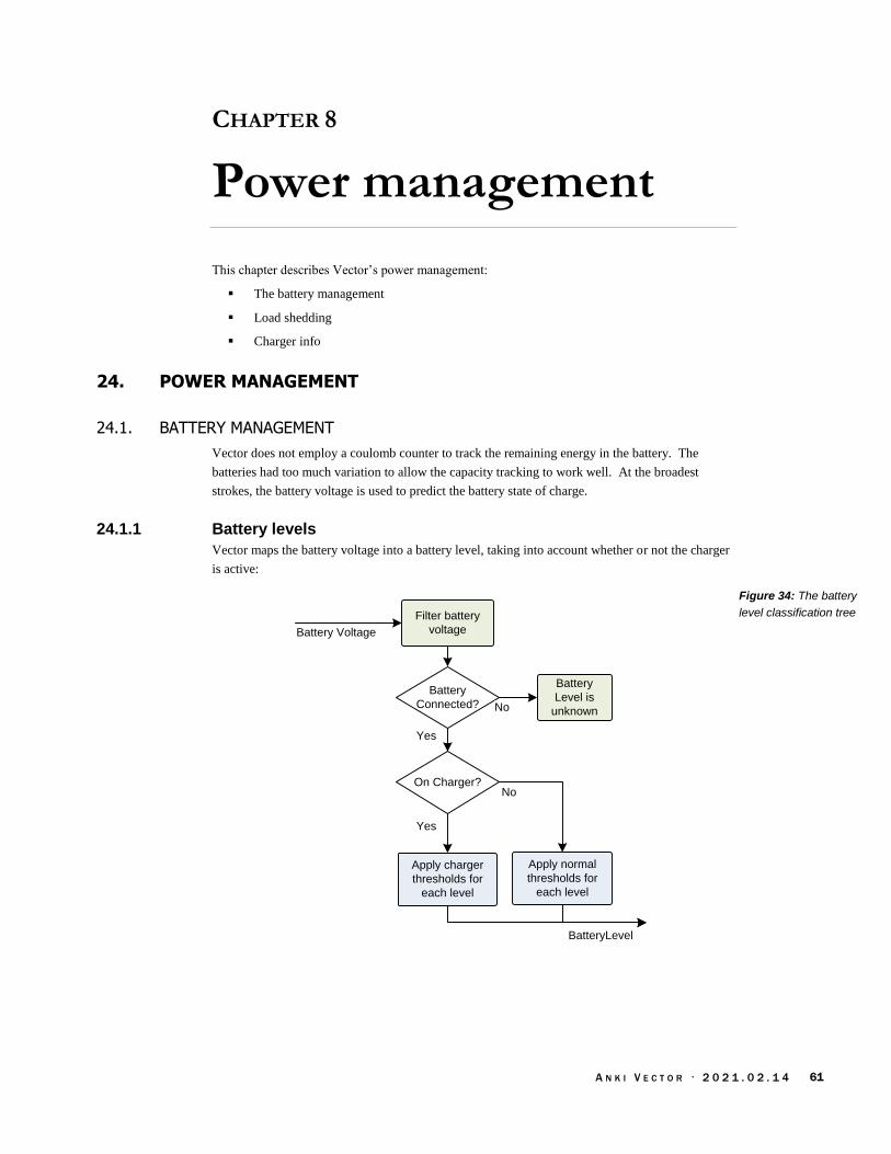
A N K I V E C T O R · 2 0 2 1 . 0 2 . 1 4 61
CHAPTER 8
Power management
This chapter describes Vector’s power management:
The battery management
Load shedding
Charger info
24. POWER MANAGEMENT
24.1. BATTERY MANAGEMENT
Vector does not employ a coulomb counter to track the remaining energy in the battery. The
batteries had too much variation to allow the capacity tracking to work well. At the broadest
strokes, the battery voltage is used to predict the battery state of charge.
24.1.1 Battery levels
Vector maps the battery voltage into a battery level, taking into account whether or not the charger
is active:
Battery
Level is
unknown
BatteryLevel
Battery Voltage
Yes
Apply charger
thresholds for
each level
On Charger?
Apply normal
thresholds for
each level
No
Battery
Connected?
Yes
No
Filter battery
voltage
Figure 34: The battery
level classification tree

A N K I V E C T O R · 2 0 2 1 . 0 2 . 1 4 62
Note: The battery voltage is filtered – the voltage will bounce around with activity by the motors,
driving the speaker and processors.
The BatteryLevel enumeration is used to categorize the condition of the Vector battery:
Name Value Description
BATTERY_LEVEL_FULL 3 Vector’s battery is at least 4.1V
BATTERY_LEVEL_LOW 1 Vector’s battery is 3.6V or less; or if Vector is on the
charger, the battery voltage is 4V or less.
BATTERY_LEVEL_NOMINAL 2 Vector’s battery level is between low and full.
BATTERY_LEVEL_UNKNOWN 0 If the battery is not connected, Vector can’t measure its
battery.
The battery levels are organized conventionally:
BATTERY_LEVEL_FULL
Any voltage at or above this threshold is
considered as a full battery
At and below this voltage, Vector begins seeking home
to charge
~3.6v BATTERY_LEVEL_LOW
Any voltage at or below this threshold triggers an
immediate battery disconnect, turning the system off
At and below this voltage, Vector performs a clean
shutdown, disabling motors, WiFi, the LCD display,
camera, etc.
4.2v
BATTERY_LEVEL_NOMINAL
When the voltage is in the range, Vector doesn’t
automatically seek the home (charger) or shutdown.
4.1v
The current battery level and voltage can be requested with the Battery State command (see
Chapter 15, section 51.2 Battery State). The response will provide the current battery voltage, and
interpreted level.
24.1.2 A software “fuel gauge”
It is typical for larger battery packs to include a coulomb counter, often called a fuel gauge. They
include it for a serious reason: it prevents fire and explosions that can result from overcharging a
large multi-cell pack. The fancy “fuel gauge” and estimated useful life is a bonus.
For Vector, a fuel gauge would given him smarts about knowing he will need to plan to return
home, or is getting low. His hardware doesn’t have a coulomb counter, for a variety of reasons.
Any effort, beyond simple battery voltage, to estimate the remaining play time would have to be
based on software and tracking the battery performance.
24.2. RESPONSES, SHEDDING LOAD / POWER SAVING EFFORTS
Vector’s main (power-related) activity modes are:
active, interacting with others
calm, where primarily sitting still, waiting for assistance or stimulation
24 The levels are from robot.py
Table 14:
BatteryLevel codes24
as they apply to
Vector
Figure 35: The battery
thresholds

A N K I V E C T O R · 2 0 2 1 . 0 2 . 1 4 63
sleeping
Depending on the state of the battery – and charging – Vector may engage in behaviours that
override others.
BatteryLevel
Level too low?
No
Yes
Level low
enough to seek
charger?
Queue high
priority task to
seek charger
Disconnect
battery
NoDone
Yes
Stuck?Yes
Low power mode,
cry for help
No
If his power is low, Vector will launch a behavior to seek the charger out, and recharge. If he is
stuck, his behaviors will have him cry out.
If Vector is unable to dock (or even locate a dock) he sheds load as he goes into a lower state:
He no longer responds to his trigger word or communicates with WiFi servers
He turns off camera and LCD; presumable the time of flight sensor as well.
He reduces processing on the processor
Eventually the power will be turned off completely.
24.2.1 Temperature limits and related processing
The software tracks the temperature of the battery and head. As the temperature rises, more
aggressive actions are taken to protect the battery and let the chips cool down.
Around 90C, Vector displays the overheating icon.
If the body board is overheated, a flag in the HTTPS API RobotStatus bit mask is set (see
Chapter 15, section 44.1.2 RobotStatus Note: this is speculated, not proven.
At some point past 90C, Vector starts a clean shut down (see earlier). The software in the
head is idle, and turns off as many peripherals (e.g. WiFi, display, etc.) with “the goal to
save enough power in the head to let the chip cool off, so we could continue driving
home.”
If the APQ8009 processor is hot, it will throttle its clocks. If the MP2617B charging chip
is reaching the thermal limits related to charging, it will throttle the charging.
Figure 36: The
response to battery
level

A N K I V E C T O R · 2 0 2 1 . 0 2 . 1 4 64
If either the body or head board exceeds a maximum temperature, the system is completely
shut down, and power is cut.
The battery overheated icon is displayed by vic-faultCodeDisplay, which has a hard coded path to
the icon:
/anki/data/assets/cozmo_resources/config/devOnlySprites/independentSprites/battery_o
verheated.png
Version 1.6 uses very conservative thresholds (to protect the battery) with the intention of follow
up releases fine tuning the thresholds.
24.2.2 Calm Power mode
Vector has a high-level power mode called “calm power mode.” This mode “is generally when
Vector is sleeping or charging.” Vector [probably] turns off the sensors, lowers the CPU and
camera clock rate – or may even suspend the camera. (See Chapter 19, section 79.5 Illumination
level sensing for a description).
Whether Vector is in calm power mode (or not) is reported in the RobotStatus message in the status
field. (See chapter 15 for details.) Vector is in a calm power model if the
ROBOT_STATUS_CALM_POWER_MODE bit is set (in the status value).
24.2.3 When not moving
When Vector isn’t driving (or using his head and lift), he puts his motors and related sensors into a
low power state:
The encoders are mostly turned off; they “pulsed at 1% duty cycle and watched for
changes” to detect someone moving Vector around;
The time of flight sensor is turned to a lower sampling period
24.3. SLEEP STATES
Vector has variety of sleep states, based on his power level, what he can potentially do, and where
he is at. These include:
Comatose
Deep sleep
Emergency sleep
Asleep, but held in palm
Asleep, on palm
Asleep on charger
Light sleep
24.3.1 Sleep Debt
Vector “has a “sleep debt” system to make him get sleepier if he's been on longer as a way of
keeping the battery and electronics from overheating (it heats up with a lot of use, but after a few
seconds of sleeping can throttle down).”
Internally Vector tracks this as an amount of time he needs to sleep (sleep_debt_hours, a floating
point number). This increments with activity (and charging), and decrements (at a different rate)
when sleeping.
Brad Neuman
reddit post
A N K I V E C T O R · 2 0 2 1 . 0 2 . 1 4 65
24.4. ACTIVITY LEVEL MANAGEMENT
Version 1.5 slowed down a lot of Vectors activities (by lowering his max clock rate), to reduce
heat (prolonging the battery service life) and allow him to play longer between charge cycles.
Some of his behaviors were modified so that he doesn’t initiate exploring and playing as much,
choosing instead to stay on the charger longer until there was more signs that people were around
to play.
Version 1.6 may have gone further.
Behaviors are responsible for requesting that Vector enter a power saving or other sleep state.
24.5. SHUTDOWN
Turning Vector off manually
Vector turning off spontaneously due to brown-out or significant loss of power
Vector turning off (under low power) by direction of the head-board
Vector turning off if key software crashes
Vector cannot be turned off via Bluetooth LE, or the local HTTPS SDK access. There are no
exposed commands that do this. Using a verbal command, like “turn off” does not direct Vector to
shut off (disconnect the battery). Instead it goes into a quiet mode. Although it may be possible
for a Cloud command to turn Vector off, this seems unlikely.
However, there is likely a command to automate the manufacture and preparation for ship process.
24.5.1 Turning Vector Off (intentionally)
When the system decides it needs to shutdown, it internally posts one of the following codes as the
reason for shutdown:
Name Value Description& Notes
SHUTDOWN_BATTERY_CRITICAL_TEMP 3 Vector shut down automatically because the battery
temperature was too high.
SHUTDOWN_BATTERY_CRITICAL_VOLT 2 Vector shut down automatically because the battery
voltage was too low.
SHUTDOWN_BUTTON 1 Vector was shut down by a long button press.
SHUTDOWN_GYRO_NOT_CALIBRATING 4 Vector shut down automatically because of an IMU
problem.
SHUTDOWN_UNKNOWN 0 Vector shut down unexpectedly; the reason is not
known. Likely a brown-out or battery voltage dipped
low faster than Vector could respond to.
The shutdown code is logged, and broadcast but not otherwise stored.
24.5.2 Unintentionally
The body-board is responsible for keeping the battery connected. However brownouts, self-
protects when the voltage get to too low, and bugs can cause the battery to be disconnected. The
body board will turn off power if it doesn’t hear from the head-board in a regular fashion. This
could be because of software crash.
Table 15: Vector
shutdown codes

A N K I V E C T O R · 2 0 2 1 . 0 2 . 1 4 66
24.5.3 Going into an off state
When Vector wants to intentionally turn off, it cleans up its state to gracefully shutdown the linux
system and tells the body-board to disconnect the battery.
24.6. THE CUBE POWER MANAGEMENT
Vector manages the Cube’s power usage by managing the link. Vector disconnects from the cube
(saving the most power) when sleeping, or the cube is not used by the behavior tree. When
connected to the cube, higher and lower update rates are selected, based on the active behavior and
the kind of interaction. Since higher update rates consume more power, Vector only employs them
if there is an indication that someone is moving or tapping the cube. Lower update rates are used
to detect the possibility of interaction, such as motion. See chapter 14 for more information.
25. CHARGING
Vector tracks whether is charging is in process, and how long. The software has some initial
estimates how long before charging is complete. This is similar to the software “fuel gauge.” It
takes some model of the batteries capacity, and typical charging times given that.
The state of the charger is reported in the RobotStatus message in the status field. (See chapter 15
for details.) Vector is on the charger if the ROBOT_STATUS_IS_ON_CHARGER bit is set (in the status
value), and charging if the ROBOT_STATUS_IS_CHARGING bit is set.
Version 1.5 slowed down the charging, to reduce heat, prolonging the battery life.
Additional information about the state of the charger can be requested with the Battery State
command (see Chapter 15, section 51.2 Battery State). The response will provide flags indicating
whether or not Vector is on the charger, and if it is charging. The response also provides a
suggested amount of time to charge the batteries.

A N K I V E C T O R · 2 0 2 1 . 0 2 . 1 4 67
CHAPTER 9
Basic Inputs and
Outputs
This chapter describes Vectors most basic input and output: his button, touch and LEDs:
Touch and button input
Backpack Lights control
Note: the audio sampling will be covered in a later chapter (Chapter 18)
26. BUTTON, TOUCH AND CLIFF SENSOR INPUT
Vector’s backpack button is used to wake (and silence) Vector, or to place him into recovery mode.
Touch is used to pet Vector and provide him stimulation. Four surface proximity IR sensors are
used to detect cliffs and line edges. The responsibility for the button, touch, and proximity sensor
input functions are divided across multiple processes and boards in Vector:
Surface
Proximity
Sensors
Surface
Proximity
Sensors
UART
Body-Board
Python SDK
applicationsVic-Gateway
Touch
Vic-Robot
Vic-Spine
ADC
ButtonGPIO
Surface
Proximity
Sensors
Time of
Flight I2C
The states of the inputs (button, touch, surface proximity and time of flight sensors) are reported in
the RobotStatus message. (See chapter 15 for details.) The button state can be found in the status
field. The button is pressed if the ROBOT_STATUS_IS_BUTTON_PRESSED bit is set (in the status
value).
The surface proximity sensors (aka “cliff sensors”) are used to determine if there is a cliff, or
potentially in the air. The individual sensor values are not accessible. The cliff detection state
can be found in the status field. A cliff is presently detected if the
ROBOT_STATUS_CLIFF_DETECTED bit is set (in the status value).
Figure 37: The touch
and button input
architecture
cliff sensors
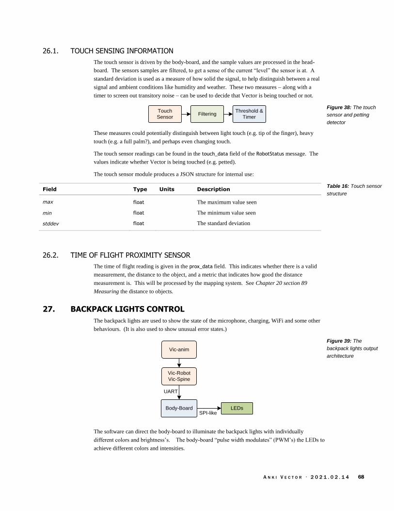
A N K I V E C T O R · 2 0 2 1 . 0 2 . 1 4 68
26.1. TOUCH SENSING INFORMATION
The touch sensor is driven by the body-board, and the sample values are processed in the head-
board. The sensors samples are filtered, to get a sense of the current “level” the sensor is at. A
standard deviation is used as a measure of how solid the signal, to help distinguish between a real
signal and ambient conditions like humidity and weather. These two measures – along with a
timer to screen out transitory noise – can be used to decide that Vector is being touched or not.
Threshold &
Timer
Touch
SensorFiltering
These measures could potentially distinguish between light touch (e.g. tip of the finger), heavy
touch (e.g. a full palm?), and perhaps even changing touch.
The touch sensor readings can be found in the touch_data field of the RobotStatus message. The
values indicate whether Vector is being touched (e.g. petted).
The touch sensor module produces a JSON structure for internal use:
Field Type Units Description
max float The maximum value seen
min float The minimum value seen
stddev float The standard deviation
26.2. TIME OF FLIGHT PROXIMITY SENSOR
The time of flight reading is given in the prox_data field. This indicates whether there is a valid
measurement, the distance to the object, and a metric that indicates how good the distance
measurement is. This will be processed by the mapping system. See Chapter 20 section 89
Measuring the distance to objects.
27. BACKPACK LIGHTS CONTROL
The backpack lights are used to show the state of the microphone, charging, WiFi and some other
behaviours. (It is also used to show unusual error states.)
UART
Body-Board
Vic-anim
LEDs
Vic-Robot
Vic-Spine
SPI-like
The software can direct the body-board to illuminate the backpack lights with individually
different colors and brightness’s. The body-board “pulse width modulates” (PWM’s) the LEDs to
achieve different colors and intensities.
Figure 38: The touch
sensor and petting
detector
Table 16: Touch sensor
structure
Figure 39: The
backpack lights output
architecture

A N K I V E C T O R · 2 0 2 1 . 0 2 . 1 4 69
The body-board doesn’t directly interface with the LED’s (they’re connected to a logic chip on a
separate board), so it cannot delegate the work to an internal PWM peripheral. The body-board
must implement its PWM in firmware, and send the GPIO states to the backpack every time there
is a change. (See Chapter 4, section 10.3.1 The LED controls)
PWM1
PWM4
PWM3
PWM2
74AHC164Octet
The basic logic to drive the LEDs is:
1. Select LEDs for the time slice
2. Get the LED bit settings from the PWM(s)
3. Organize these into a format for the 74AHC164
4. Send the bits to the 74AHC164
5. Delay until the next time slice, and repeat
Figure 40: The
firmware driving of the
LEDs

A N K I V E C T O R · 2 0 2 1 . 0 2 . 1 4 70
CHAPTER 10
Inertial Motion
Sensing
This chapter describes Vector’s motion sensing:
Sensing motion and cliffs
Detecting external events
Measuring motion as feedback to motion control, and allow moving along paths in a
smooth and controlled fashion
28. MOTION SENSING
Vector employs an IMU – an accelerometer and gyroscope in the same module – to detect motion,
such as falling or being bumped, as well as measuring the results of motor-driven motions.
IMU IMU Filter
Pick Up / In-
Air Detector
Cliff
Sensors
Poke
Detector
Being Held
Detector
Fall
Detector
Fist-Bump
Detector
28.1. ACCELEROMETER AND GYROSCOPE
Neither the accelerometer nor gyroscope by itself is sufficient to accurately measure change in
position and orientation. Accelerometers measure force along 3 (XYZ) axes, including gravity.
The accelerometer provides the orientation – if there is no other motion. The drawback is that
accelerometers cannot correctly measure spins, and other rotations from other movements.
Gyroscopes can measure rotations around the axes, but cannot measure linear motion along the
axis. Gyroscopes also have a slight bias in the signal that they measure, giving the false signal that
there is always some motion occurring.
By blending the accelerometer and gyroscope signals together, they can compensate and cancel
each other’s weaknesses out.
Figure 41: Sensing
motion events

A N K I V E C T O R · 2 0 2 1 . 0 2 . 1 4 71
AcelerometerLow pass
filter
Angular
Velocity
GyroscopeHigh pass
filter
Displacement
Numerical
integration
Numerical
integration
High pass
filter
Angle
28.2. TILTED HEAD
The IMU can also measure how tilted Vector’s head is. The IMU is located in Vector’s head. This
presents a small extra step of processing for the software to accommodate the impact of the head.
By combining the position & orientation of the IMU within the head, the current estimated angle of
the head, the known joint that the head swivels on, and working backwards the IMU measures can
be translated to body-centered measures.
28.3. SENSING MOTION
The IMU’s primary function is detect motion – to help estimate the change in position, and
changes in orientation of Vector’s body, and how fast it is moving.
The IMU can be used to detect the angle of Vector’s body. This is important, as the charging
behaviour uses the tilt of the charging station ramp to know that it is in the right place.
28.4. SENSING INTERACTIONS
The IMU (with some help from the cliff sensors) is also used to sense interactions and other
environmental events – such as being picked up or held by a person, being poked or given a fist
bump, or falling.
Acelerometer
Gyroscope
ClassifierFilter bankLow pass
filterFilter bank
Filter bankLow pass
filterFilter bank
By using combinations of high, low pass, and band filters, and looking for signature patterns,
Vector identify the kinds of physical interactions that are occurring.
The taps and pokes may tilt Vector, but will also provide a “frequency” response to the signals that
can be used to trigger on. The movement will change his position quickly and slight in small
distance, but Vector will resume his prior position very quickly.
Fist-bumps are like pokes, except that the lift has already been raised, and most of the frequency
response and motion will be predictable from receiving the bump on the lift.
Figure 42:
Complementary
filtering of the
accelerometer and
gyroscope
Figure 43: Classify
movement by filtering
the accelerometer and
gyroscope signals

A N K I V E C T O R · 2 0 2 1 . 0 2 . 1 4 72
Fall detection is similar. In free-fall, the force measured by the accelerometer gets very small. If
Vector is tumbling, there is a lot of angular velocity that is taking Vector off of his driving surface.
Being picked up is distinct because of the direction of acceleration and previous orientation of
Vector’s body.
Being held is sensed, in part by first being picked up, and by motions that indicate it is not on a
solid surface.
A similar set of interaction sensing is present with the cube. It can sense that it is being tapped (or
double tapped), picked up, and held. See Chapter 21.
Patent filings (e.g. WO 2019/173321 indicates that Anki had ideas of how this could be extended
to detect riding in a car, and even estimating how fast it is moving.
29. REFERENCES AND RESOURCES
AdaFruit, https://github.com/adafruit/Adafruit_9DOF/blob/master/Adafruit_9DOF.cpp
An example of how accelerometer and gyroscope measurements are fused.
Anderson, Ross Robot Transportation Mode Classification, Anki, WIPO WO 2019/173321 A1,
2019 Sept 12

A N K I V E C T O R · 2 0 2 1 . 0 2 . 1 4 73
PART III
Communication
This part provides details of Vector’s communication protocols. These chapters describe structure
communication, the information that is exchange, its encoding, and the sequences needed to
accomplish tasks. Other chapters will delve into the functional design that the communication
provides interface to.
COMMUNICATION. A look at Vector’s communication stack.
COMMUNICATION WITH THE BODY-BOARD. The protocol that the body-board responds to.
VECTOR’S BLUETOOTH LE COMMUNICATION PROTOCOL. The Bluetooth LE protocol that
Vector responds to.
CUBE’S BLUETOOTH LE COMMUNICATION PROTOCOL. The Bluetooth LE protocol that the
companion cube responds to.
SDK PROTOCOL. The HTTPS protocol that Vector responds to.
WEB-VISUALIZATION PROTOCOL. The web-sockets protocol(s) that Vector provides for
debugging in development builds.
CLOUD. A look at how Vector interacts with remote services
drawing by Jesse Easley

A N K I V E C T O R · 2 0 2 1 . 0 2 . 1 4 74
[This page is intentionally left blank for purposes of double-sided printing]
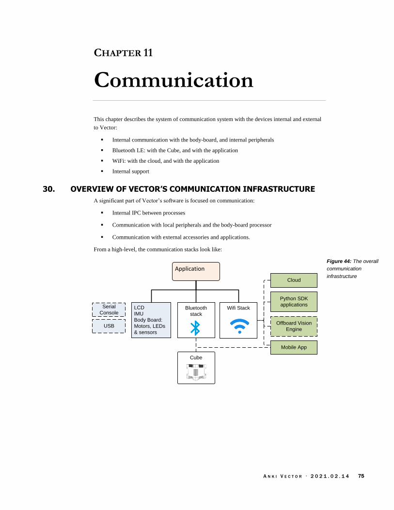
A N K I V E C T O R · 2 0 2 1 . 0 2 . 1 4 75
CHAPTER 11
Communication
This chapter describes the system of communication system with the devices internal and external
to Vector:
Internal communication with the body-board, and internal peripherals
Bluetooth LE: with the Cube, and with the application
WiFi: with the cloud, and with the application
Internal support
30. OVERVIEW OF VECTOR’S COMMUNICATION INFRASTRUCTURE
A significant part of Vector’s software is focused on communication:
Internal IPC between processes
Communication with local peripherals and the body-board processor
Communication with external accessories and applications.
From a high-level, the communication stacks look like:
LCD
IMU
Body Board:
Motors, LEDs
& sensors
Application
Mobile App
Cloud
Serial
ConsoleWifi Stack
Python SDK
applicationsBluetooth
stack
Cube
USBOffboard Vision
Engine
Figure 44: The overall
communication
infrastructure
A N K I V E C T O R · 2 0 2 1 . 0 2 . 1 4 76
31. INTERNAL COMMUNICATION WITH PERIPHERALS
The communication stack within the software is one part Linux, one part Qualcomm, and a big
heaping dose of Anki’s stuff.
31.1. COMMUNICATION WITH THE BODY-BOARD
The head board communicates with the body board using a serial interface. The device file is
/dev/ttyHS0.
31.2. SERIAL BOOT CONSOLE
The head-board employs a serial port to display kernel boot up and log messages. The
parameters are 115200 bits/sec, 8 data bits no parity, 1 stop bit; the device file is /dev/ttyHSL0.
This serial port is not bi-directional, and can not be used to login.
31.3. USB
There are pins for USB on the head board. Asserting “F_USB” pad to VCC enables the port.
During power-on, and initial boot it is a Qualcomm QDL port. The USB supports a Qualcomm
debugging driver (QDL), but the readout is locked. It appears to be intended to inject software
during manufacture.
The /etc/initscriptsusb file enables the USB and the usual functionfs adb. It lives in
/sbin/usr/composition/9091 (I think, if I understand the part number matching correctly). This
launches ADB (DIAG + MODEM + QMI_RMNET + ADB)
Vectors log shows the USB being disabled 24 seconds after linux starts. It is enabled only on
development units.
32. BLUETOOTH LE
Bluetooth LE is used for two purposes:
1. Bluetooth LE is used to initially configure Vector, to reconfigure him when the WiFi
changes; and to pair him to with the companion cube accessory. Potentially allows some
diagnostic and customization.
2. Bluetooth LE is used to communicate with the companion Cube: to detect its movement,
taps, and to set the state of its LEDs.
Melanie T
Melanie T

A N K I V E C T O R · 2 0 2 1 . 0 2 . 1 4 77
Vector’s Bluetooth LE stack looks like:
Bluez
/data/misc/bluetooth/abtd.socket
ankibluethd
Cube library
libcubeBleClient
Qualcomm
Bluetooth LE
libanki-ble
Vic-
Switchboard
/data/misc/bluetooth/btprop
The elements of the Bluetooth LE stack include:
Element Description & Notes
ankibluetoothd A server daemon. The application layer communicates with it
over a socket; /data/misc/bluetooth/abtd.socket
BlueZ Linux’s official Bluetooth stack, including Bluetooth LE support.
The Anki Bluetooth daemon interacts with it over a socket: /data/misc/bluetooth/btprop
bccmd A Bluetooth core command
btmon A command-line Bluetooth tool
libanki-ble.so Communicates with Anki Bluetooth daemon probably serves both
the external mobile application interface and communication with
the companion cube.
libcubeBleClient.so25 A library to communicate with the companion cube, play
animations on its LEDs, detect being held, taps and the cube’s
orientation.
viccubetool Probably used to update the firmware in the Cube.
25 The library includes a great deal of built in knowledge of the state of application (“game engine”), animations, and other elements
Figure 45: The
Bluetooth LE stack
Table 17: Elements of
the Bluetooth LE stack
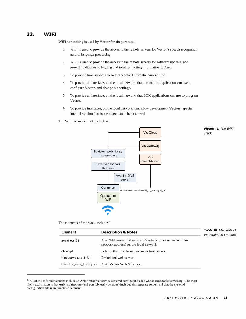
A N K I V E C T O R · 2 0 2 1 . 0 2 . 1 4 78
33. WIFI
WiFi networking is used by Vector for six purposes:
1. WiFi is used to provide the access to the remote servers for Vector’s speech recognition,
natural language processing
2. WiFi is used to provide the access to the remote servers for software updates, and
providing diagnostic logging and troubleshooting information to Anki
3. To provide time services to so that Vector knows the current time
4. To provide an interface, on the local network, that the mobile application can use to
configure Vector, and change his settings.
5. To provide an interface, on the local network, that SDK applications can use to program
Vector.
6. To provide interfaces, on the local network, that allow development Vectors (special
internal versions) to be debugged and characterized
The WiFi network stack looks like:
Connman
Avahi mDNS
server
libvictor_web_libray
libcubeBleClient
Qualcomm
WiF
/net/connman/service/wifi_..._managed_psk
Vic-
Switchboard
Vic-Gateway
Civet Webserver
libcivetweb
Vic-Cloud
The elements of the stack include:26
Element Description & Notes
avahi 0.6.31 A mDNS server that registers Vector’s robot name (with his
network address) on the local network;
chronyd Fetches the time from a network time server.
libcivetweb.so.1.9.1 Embedded web server
libvictor_web_library.so Anki Vector Web Services.
26 All of the software versions include an Anki webserver service systemd configuration file whose executable is missing. The most
likely explanation is that early architecture (and possibly early versions) included this separate server, and that the systemd configuration file is an unnoticed remnant.
Figure 46: The WiFi
stack
Table 18: Elements of
the Bluetooth LE stack

A N K I V E C T O R · 2 0 2 1 . 0 2 . 1 4 79
33.1. FIREWALL
The network configuration includes a firewall set up with the usual configuration files:
/etc/iptables/iptables.rulesiptables /etc/iptables/ip6tables.rulesiptables
Is set to block incoming traffic (but not internal traffic), except for:
1. Responses to outgoing traffic
2. DHCP
3. TCP port 443 for vic-gateway
4. UDP port 5353 for mDNS (Avahi)
5. And the ping ICMP
In developer builds the firewall also allows:
1. SSH access
2. Android Debugger (ADB) over TCP access
3. “Web-viz” access, which has web-server / websockets / webdav ports
4. Webots support
5. WWise profiler support
The firewall does not block outgoing traffic
33.2. WIFI CONFIGURATION
The WiFi is configured by the Vic-switchboard over Bluetooth LE. The WiFi settings cannot be
changed by the remote servers or thru the WiFi-based API; nor is information about the WiFi
settings is not stored remotely.
The WiFi is managed by connman thru the Vic-Switchbox:
To provide a list of WiFi SSIDs to the mobile app
To allow the mobile app to select an SSID and provide a password to
Tell it forget an SSID
To place the WiFi into Access Point mode
The connman settings – files for accessing known WiFi access points – are stored on the encrypted
file-system /data, in the folder:
/data/lib/connman
The path is hard-coded into connman itself. This folder is created (if it doesn’t exist) by mount-
data when it sets /data up for the robot (such as when it is new or has had its user data erased via
the “Clear User Data” menu). The contents of /var/lib/connman are copied here with each system
start.

A N K I V E C T O R · 2 0 2 1 . 0 2 . 1 4 80
33.3. ACCESS POINT MODE
Vector can acted as a wifi access point, instead of connecting to a router. This was primarily
intended to ease development of Vector. With the OpenSource Kit this is more useful. Vector can
be put into access point mode by issuing a command over the Bluetooth LE channel.
34. NETWORK COMMUNICATION
34.1. COMMUNICATING WITH MOBILE APP AND SDK
Vector’s robot name is something that looks like “Vector-E5S6”. This name is used consistently;
it will be Vector’s:
advertised Bluetooth LE peripheral name (although spaces are used instead of dashes)
mDNS network name (dashes are used instead of spaces),
the name used to sign certificates, and
it will be the name of his WiFi Access Point, when placed into Access Point mode
34.1.1 Certificate based authentication
A certificate is generated by Vector for use with the HTTPS API and vic-gateway. The certificate
allows the mobile application and SDK-based application to validate that they are talking to the
robot that they think they are. This is optional: the applications don’t need to use it, if they do not
wish to. So what are certificates?
“Certificates can be thought of as policy documents. Any X.509 certificate consists of
“a public key,
“an indication who the certificate was issued for,
“what actions the authority allows the certificate holder to perform,
“the date the certificate is first valid on,
“the date the certificate expires on,
“metadata about how to check if the certificate has been revoked (optional, but highly
recommended),
“the authority who issued the certificate, and
“a signature across all this metadata, from the authority.”
The certificate is created by the vic-gateway-cert.service (which in turn calls the /sbin/vic-
gateway-cert script) at start-up, after the “factory reset.” When the user data is cleared, the old
certificates and robot name are cleared as well. Vector is assigned a new robot name when the
system restarts (after clearing), and then creates a new certificate.
The certificate is stored on the robot at:
/data/vic-gateway/gateway.cert
The path is hard-coded into both vic-cloud and vic-gateway. Vector posts the certificate to the
cloud servers using vic-cloud. The mobile application and SDK-based applications receive the
certificate from these servers.
Phil Vachon

A N K I V E C T O R · 2 0 2 1 . 0 2 . 1 4 81
Mobile App
SDK application
vic-cloud Anki Cloud
vic-gateway-cert
servicegateway.cert
The following is a synopsis of the files and scripts involved with the API certificate:
File Description
/anki/etc/vic-gateway-cert.env Holds the fault code if the vic-gate-cert.service fails.
/data/etc/robot.pem The private key is generated after a factory reset by mount-data.
/data/vic-gateway/gateway.cert The certificate used by the mobile application and SDK apps to validate the
authenticity of the robot.
/etc/systemd/system/vic-gateway-cert.service
The startup service responsible for creating the certificate (if there isn’t one
already)
/etc/vic-gateway-cert.conf.in The template (default field values) used in creating the certificate.
/sbin/vic-gateway-cert The script that creates the certificate
vic-cloud Posts the certificate to the cloud
vic-gateway Uses the robot.pem as the private key for TLS communication with the mobile
application and SDK.
This certificate is intended to be added to the trusted SSL certificates store before a HTTPS
communication session. The certificate issued by Vector is good for 100 years. The following is
information typically embedded in a Vector certificate:
Element Value
Common Name Vector’s robot name
Subject Alternative Names Vector’s robot name
Organization Anki
Locality SF
State California
Country US
Valid From the date the certificate was created
Valid To 100 years after the date the certificate was created
Issuer Vector’s robot name, Anki
Serial Number
Figure 47: The
certificate flow from
the robot to the mobile
application
Table 19: The files,
scripts and programs
involved with the API
certificate
Table 20: Elements of
a Vector certificate

A N K I V E C T O R · 2 0 2 1 . 0 2 . 1 4 82
34.1.2 Token
A session token is provided by Anki servers27 to the mobile application and HTTPS-based SDK
application. This token is required to by the robot to validate that they application is talking to has
authenticated itself as an owner.
App Vector
Name & password
Session Token
Session Token
Client Token
Server
When the application(s) receive the session token from the server, they must pass it to Vector via
the Bluetooth LE RTS protocol or the HTTPS SDK protocol. The process to is generated it is
initiated in one of two ways. One method is by the Bluetooth LE command (section 40.9 Cloud
session); the other is by send a User Authentication command (see Chapter 15 section 52.5 User
Authentication). Vector will return a client token. (The session token is single use only.) The
application(s) should save this client token for future uses (it can be used indefinitely).
Vector stores information about the session and client tokens in a file at:
/data/vic-gateway/token-hashes.json
This file has a single structure with the following fields:
Field Type Description
client_tokens ClientToken[] The array of client tokens.
The ClientToken structure has the following fields:
Field Type Description
app_id string This is the name given by an application using the API. Common ones
include “companion-app” for the mobile application, and “SDK” for the
python SDK based authentication. Optional.
client_name string The name of computer requesting the client token. Optional.
hash base64 string
is_primary bool Unknown This is always false.
issued_at string The date-time that the hash / client token was created
34.2. WEB-VIZ, A VISUAL CHARACTERIZATION TOOL
Development builds of Vectors software include an optional web-sockets API and web-
visualization (webviz) tool. This feature is not present in the production releases, nor many of the
development releases. With this tool has some of the vic-server processes provide an HTTP web-
server, and web socket over it:
27 https://groups.google.com/forum/#!msg/anki-vector-rooting/YlYQsX08OD4/fvkAOZ91CgAJ https://groups.google.com/forum/#!msg/anki-vector-rooting/XAaBE6e94ek/OdES50PaBQAJ
Figure 48: Sequence for
acquiring a client token
Table 21: The token
hashes structure
Table 22: The
ClientToken structure

A N K I V E C T O R · 2 0 2 1 . 0 2 . 1 4 83
Port Description
8887 The webserver built into vic-webserver
8888 The webserver built into vic-engine
8889 The webserver built into vic-anim
8890 Not used
The web-sockets provide access to internal variables and other software state. In some cases
provide points of control. The web-server, esp thru the webdav support, allows files to be
downloaded and uploaded into Vector. This includes the ability to add animation files that can be
tested.
Note: the tool is rumoured to be consume a lot of resources, causing unusual faults to occur on
Vector. It has a small overlap with the functions can be taken via the SDK interface.
35. CLOUD SERVERS
The cloud servers are used for natural language processing, storing settings, tracking diagnostic
information, and software updates.
Chipper
Handoff
Lex
Automatic Speech
Recognition &
Language
understanding
Houndify
Automatic Speech
Recognition &
Knowledge Q&A
IBM Weather
Weather related
Q&A
JDocs server
For natural language processing, the audio stream (after the “Hey Vector”) is sent to a group of
remote servers for processing. The functions are divided up across several different servers which
can provide specialized services:
Server Description
Chipper Chipper is a server that that hands off the audio processing.
Houndify The “knowledge graph” Q&A server is handled by Sound Hound
(Houndify). Note: the speech is sent to Houndify only if Lex is unable to
handle the query.
IBM Weather IBM handles the Weather related questions.
Lex Lex handles most of Vectors speech recognition, natural language
understanding, return an intent. (This is discussed a bit more in Chapter
18) The “I have a question” queries are handed off to Houndify. This
server is hosted by AWS.
Table 23: Web-viz
HTTP & web-socket
server ports
Figure 49: The cloud
servers
Table 24: Natural
language processing
servers
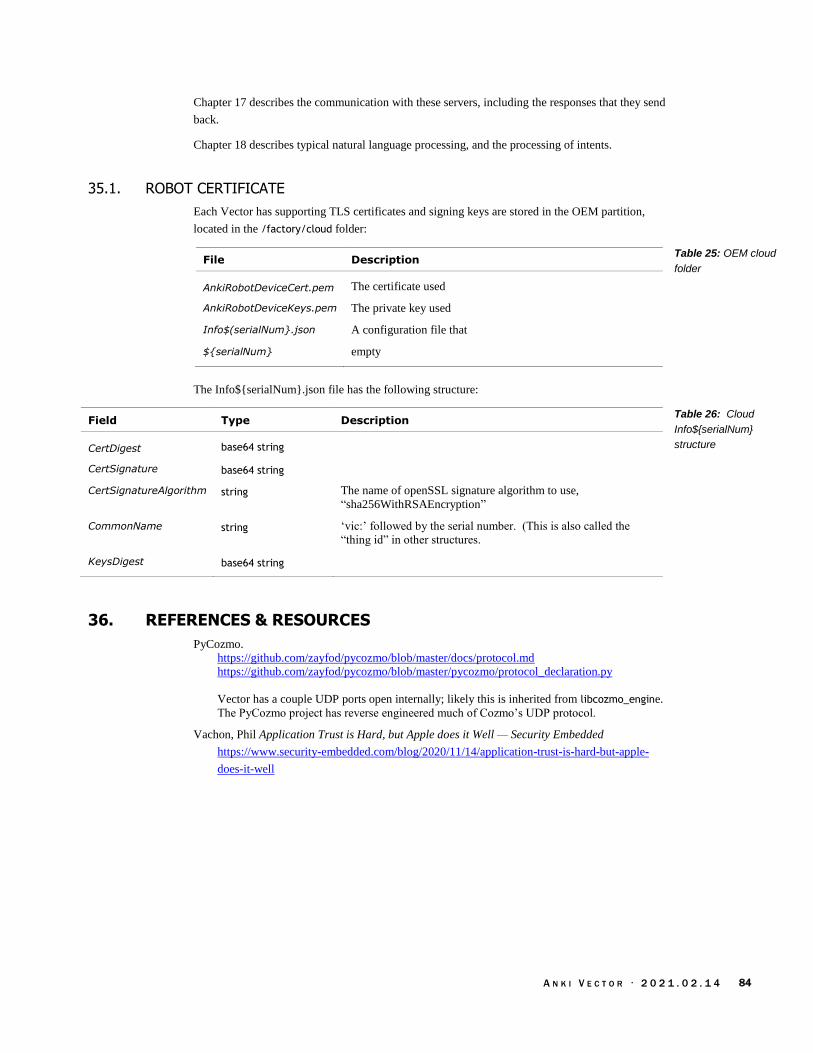
A N K I V E C T O R · 2 0 2 1 . 0 2 . 1 4 84
Chapter 17 describes the communication with these servers, including the responses that they send
back.
Chapter 18 describes typical natural language processing, and the processing of intents.
35.1. ROBOT CERTIFICATE
Each Vector has supporting TLS certificates and signing keys are stored in the OEM partition,
located in the /factory/cloud folder:
File Description
AnkiRobotDeviceCert.pem The certificate used
AnkiRobotDeviceKeys.pem The private key used
Info$(serialNum}.json A configuration file that
${serialNum} empty
The Info${serialNum}.json file has the following structure:
Field Type Description
CertDigest base64 string
CertSignature base64 string
CertSignatureAlgorithm string The name of openSSL signature algorithm to use,
“sha256WithRSAEncryption”
CommonName string ‘vic:’ followed by the serial number. (This is also called the
“thing id” in other structures.
KeysDigest base64 string
36. REFERENCES & RESOURCES
PyCozmo.
https://github.com/zayfod/pycozmo/blob/master/docs/protocol.md
https://github.com/zayfod/pycozmo/blob/master/pycozmo/protocol_declaration.py
Vector has a couple UDP ports open internally; likely this is inherited from libcozmo_engine.
The PyCozmo project has reverse engineered much of Cozmo’s UDP protocol.
Vachon, Phil Application Trust is Hard, but Apple does it Well — Security Embedded
https://www.security-embedded.com/blog/2020/11/14/application-trust-is-hard-but-apple-
does-it-well
Table 25: OEM cloud
folder
Table 26: Cloud
Info${serialNum}
structure

A N K I V E C T O R · 2 0 2 1 . 0 2 . 1 4 85
CHAPTER 12
Body-board
Communication
Protocol
This chapter describes Vector’s body-board communication protocol.
The kinds of activities that can be performed
The interaction sequences
The communication protocol stack.
37. COMMUNICATION PROTOCOL OVERVIEW
Communication with the body-board, once established, is structured as a request-response protocol
and a streaming data update. The data of the messages was packaged using an proprietary tool
called “C-Like Abstract Data structures” (CLAD) that made it easy for Anki to define message
structures – fields and values in a defined format – and generate code to encode and decode them.
The messages from the head board to the body-board have the content:
Checking that the application firmware is running and its version
Boot-loader updates to the firmware: Entering the boot-loader, erasing flash, writing a new
application, and verifying it
The 4 LED RGB states
Controls for the motors: possible direction and enable; direction and duty cycle; or a target
position and speed.
Power control information: disable power to the system, turn off distance, cliff sensors, etc.
In turn, the body board messages to the head-board can contain (depending on the type of packet):
The touch sensor ADC value, and state of the backpack button
The microphone samples for all 4 microphones. (Most likely as 16 bits per sample)
The battery voltage,
The charging terminal voltage
State of the charger – on docked, charging, battery critically low
The temperature of the charger/battery
The state of 4 motor encoders, possibly as encoder counters, possibly as IO state
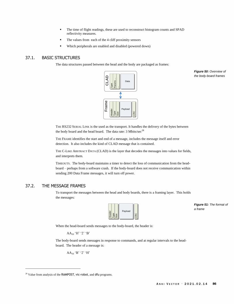
A N K I V E C T O R · 2 0 2 1 . 0 2 . 1 4 86
The time of flight readings, these are used to reconstruct histogram counts and SPAD
reflectivity measures.
The values from each of the 4 cliff proximity sensors
Which peripherals are enabled and disabled (powered down)
37.1. BASIC STRUCTURES
The data structures passed between the head and the body are packaged as frames:
Fra
me
He
ad
er
Typ
e
Payload
Siz
e
CR
C
CL
AD
Typ
e
Pa
ram
s ...
Data
...
THE RS232 SERIAL LINK is the used as the transport. It handles the delivery of the bytes between
the body board and the head board. The data rate: 3 Mbits/sec28
THE FRAME identifies the start and end of a message, includes the message itself and error
detection. It also includes the kind of CLAD message that is contained.
THE C-LIKE ABSTRACT DATA (CLAD) is the layer that decodes the messages into values for fields,
and interprets them.
TIMEOUTS. The body-board maintains a timer to detect the loss of communication from the head-
board – perhaps from a software crash. If the body-board does not receive communication within
sending 200 Data Frame messages, it will turn off power.
37.2. THE MESSAGE FRAMES
To transport the messages between the head and body boards, there is a framing layer. This holds
the messages:
He
ad
er
Typ
e
Payload
Siz
e
CR
C
When the head-board sends messages to the body-board, the header is:
AA16 ‘H’ ‘2’ ‘B’
The body-board sends messages in response to commands, and at regular intervals to the head-
board. The header of a message is:
AA16 ‘B’ ‘2’ ‘H’
28 Value from analysis of the RAMPOST, vic-robot, and dfu programs.
Figure 50: Overview of
the body-board frames
Figure 51: The format of
a frame

A N K I V E C T O R · 2 0 2 1 . 0 2 . 1 4 87
The rest of the frame:
The payload type is 16 bits. The packet type implies both the size of the payload, and the
contents. If the packet type is not recognized, or the implied size does not match the
passed payload size, the packet is considered in error.
The payload size is a 16 bit number. The maximum payload size is 1280 bytes.
The CRC is 32 bits. It is computed on the payload only.
The tag and CLAD payload are passed to the application for interpretation.
37.3. ACKNOWLEDGEMENT AND NEGATIVE ACKNOWLEDGEMENT OF MESSAGES
Sends a message to the body-board. If the message doesn’t pass CRC checks, or the command is
not recognize, the body-board sends a NAK.
Head-Board Body-Board
Command
NAK
Otherwise it may attempt to carry out the command, and it may send back an ACK or other
response on success… or a NAK on error.
37.4. UPDATING THE FIRMWARE APPLICATION
The head-board can update the firmware in the body-board, by putting it into DFU (device
firmware upgrade) mode and downloading the replacement firmware image. If the head-board
application decides to download a (new) application to the body-board – for instance, if the version
is out of date – it does so with a sequence like:
Head-Board Body-Board
Version request
Version response
DFU mode
ACK
...
File download
File download
737416
1. Checking the version. Compares this with the version of the latest file.
2. It sends the 787816 command to erase the current application
3. It sends a serial sequence of the application data using the 667516 command.
4. Then the 737416 command is sent to validate the command (including checking its
authenticity using a digital signature), and start the application.
5. The boot-loader sends the results of the check in a 6B6116 response. The head-board
application check results, then if successful,
Figure 52: Body-board
NAK a CRC-error or bad
command
Figure 53: Sequence for
updating the body-board

A N K I V E C T O R · 2 0 2 1 . 0 2 . 1 4 88
6. It waits for message frames from the body-board application.
37.4.1 The format of the firmware update file
The first 16 bytes of the firmware update files holds the version. This is used only for comparing
versions. It is not sent. The remainder of the file holds the application firmware. The following
summarizes where the application firmware is placed into the STM32F030 program memory:
STM32F030 Program Memory
0x0800 0000: Bootloader
0x0800 2000: Application Control Block
0x0800 2020: Unknown
0x0800 2118: Application Entry
0x0800 211C: Application Version
0x0800 212C-: Application
0x0800 57xx: Application Vector Table
0x0800 5800-: Application
0x0800 FFFF :
Version
16 bytes
Application
firmware
Note: I don’t know what points to the vector table.
37.5. COMMAND-LINE INTERFACE
The body-board has a bidirectional serial interface for test purposes. This is located on the charger
positive pad. The single connection is half-duplex – it is used to both send and receive. The data
rate is 115.2 Kbits/sec.
Note: this communication is only implemented in DVT firmware; it is not implemented in
production firmware. It is not known how to put the DVT firmware into this mode.
When the body board powers on it sends a few header bytes and a string:
FF16 9216 1F16 CF16 FF16 FF16 FF16 FF16 “\\nbooted\n”
Thereafter body-board can receive characters from this interface and forward them with the 636416
message to the head-board for processing by vic-robot.
1. vic-robot receives these characters, and buffers them. When it sees a new line or carriage
return, it examines the line. If the line starts with a ‘>’ and is followed by a valid 3-letter
command, it will carry out the command. This may include reporting sensed values,
writing the factor calibration values or EMR.
2. If vic-robot wishes to send text, via the body-boards outgoing serial port, it uses the 636416
command to send the text characters to the body-board, which then sends them out the
charger port.
The text commands from this port are that vic-robot recognizes are:
esn
bsv
mot
Figure 54: The
STM32F030 program
memory map

A N K I V E C T O R · 2 0 2 1 . 0 2 . 1 4 89
get
fcc
rlg
eng
smr
gmr
pwr
led
38. MESSAGE FORMATS
This section describes the format and interpretation of the CLAD messages that go between the
body-board and head-board. It describes the fields and how they are encoded, etc.
All multi-byte values are in little endian order
The letters to describe the frame type are in the order sent (effectively the opposite of the 16-
bit values)
The following kinds of messages can be sent from the head-board to the body-board:
Frame type Payload Size Description
636416 ‘dc’
32 Appears to allow sending text back to the body board and
out its backs end. [Data character? charger data?] Note:
this message is not supported in production application
firmware (i.e. 1.6).
646616
‘fd’ 64 Data frame. This has all the bits for the LEDs, motor
drivers, power controls, etc.
647316 ‘sd’
0 Shutdown: disconnect the battery, to shutoff the system.
667516
‘uf’ 1028 Update firmware frame. Sends a 1024B as part of the
DFU payload. The first 16b is the offset in the program
memory to update; the next 16b are the number of 32-bit
words in the payload to write. (The packet is a fixed size,
so may be padded out)
6D6416
‘dm’ 0 Go to DFU mode? Goto app mode? Change the mode:
enter the boot-loader? start regular reports?
727616
‘vr’ 0 Requests the application version. If there is an
application, it responds with a 727616. If there isn’t
application, the boot-loader responds with a 6B6116 with a
0 payload (a NAK).
736C16
‘ls’ 16 LED control
737416
‘ts’ 0 Validate the flash, to check that the newly downloaded
program and that it passed signature checks. The boot-
loader sends back a 6B6116 to ACK to indicate that the
firmware passed checks, or NACK that it does not. If
successful, the application is started. [Test?]
787816
‘xx’ 0 Erases the current program memory (the currently
installed image). The boot-loader sends back a 6B6116 to
acknowledge that the erase when it has completed.
Table 27: Summary of
the commands from the
head-board to the body-
board

A N K I V E C T O R · 2 0 2 1 . 0 2 . 1 4 90
The following kinds of messages can be sent from the body-board to the head-board:
Fame type Payload Size Description
636416
‘dc’
32 Appears to include characters. Note: this message is not
supported in production application firmware (i.e. 1.6).
646616
‘fd’ 768 Data frame. Battery state – level, temperature, flags
The size of the message suggests that it holds 128 samples
from one to three microphones (4 microphones ×
2bytes/sample × 80 samples/microphone == 768 bytes)
for the voice activity detection audio processing.
666216
‘bf’ Boot-loader frames
6b6116
‘ak’ 4 The value is non-zero if an ack
727616
‘vr’ 40 The first 28 payload bytes are TBD. This is followed by a
16-byte version (often printable characters). The first 16
bytes of the DFU file are also the version.
737616
‘vs’ 16 Note: this message is not supported in production
application firmware (i.e. 1.6).
38.1. ENUMERATIONS
These are the indices that the communication uses to refer to sensors, motors, etc.
38.1.1 Cliff Sensors
The cliff sensors indices are:
Index Meaning
0 The front-left cliff sensor.
1 The front-right cliff sensor.
2 The back-left cliff sensor.
3 The back-right cliff sensor.
38.1.2 Motors
The motor indices are:
Index Meaning
0 The left wheel motor.
1 The right wheel motor
2 The lift motor.
3 The head motor.
Table 28: Summary of
the messages from the
body-board to the head-
board
Table 29: Cliff sensor
enumeration
Table 30: Motor
enumeration
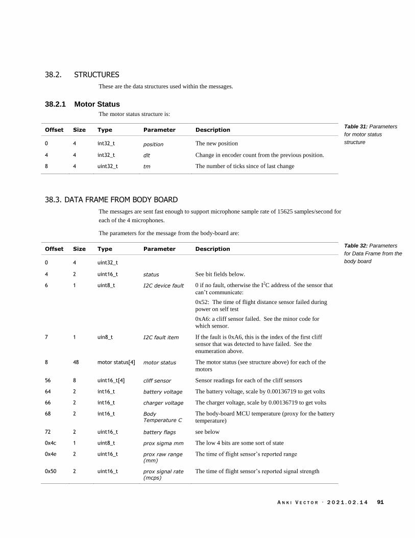
A N K I V E C T O R · 2 0 2 1 . 0 2 . 1 4 91
38.2. STRUCTURES
These are the data structures used within the messages.
38.2.1 Motor Status
The motor status structure is:
Offset Size Type Parameter Description
0 4 int32_t position The new position
4 4 int32_t dlt Change in encoder count from the previous position.
8 4 uint32_t tm The number of ticks since of last change
38.3. DATA FRAME FROM BODY BOARD
The messages are sent fast enough to support microphone sample rate of 15625 samples/second for
each of the 4 microphones.
The parameters for the message from the body-board are:
Offset Size Type Parameter Description
0 4 uint32_t
4 2 uint16_t status See bit fields below.
6 1 uint8_t I2C device fault 0 if no fault, otherwise the I2C address of the sensor that
can’t communicate:
0x52: The time of flight distance sensor failed during
power on self test
0xA6: a cliff sensor failed. See the minor code for
which sensor.
7 1 uin8_t I2C fault item If the fault is 0xA6, this is the index of the first cliff
sensor that was detected to have failed. See the
enumeration above.
8 48 motor status[4] motor status The motor status (see structure above) for each of the
motors
56 8 uint16_t[4] cliff sensor Sensor readings for each of the cliff sensors
64 2 int16_t battery voltage The battery voltage, scale by 0.00136719 to get volts
66 2 int16_t charger voltage The charger voltage, scale by 0.00136719 to get volts
68 2 int16_t Body
Temperature C
The body-board MCU temperature (proxy for the battery
temperature)
72 2 uint16_t battery flags see below
0x4c 1 uint8_t prox sigma mm The low 4 bits are some sort of state
0x4e 2 uint16_t prox raw range
(mm)
The time of flight sensor’s reported range
0x50 2 uint16_t prox signal rate
(mcps)
The time of flight sensor’s reported signal strength
Table 31: Parameters
for motor status
structure
Table 32: Parameters
for Data Frame from the
body board

A N K I V E C T O R · 2 0 2 1 . 0 2 . 1 4 92
0x52 2 uint16_t prox ambient The time of flight sensor’s reported ambient noise
0x54 2 uint16_t prox SPAD count The time of flight sensor’s reported SPAD count
0x56 2 uint16_t prox sample
count
The time of flight sensor’s reported sample count
0x58 4 uint32_t prox calibration
result
92 4 uint16_t[2] Index 1 is the button, 0 is the touch sense ADC?
96 4 uint16_t[2] Something to do with the microphones, appears to be
indices to the buffers being used.
100 2 uint16_t Something related to the button inputs
102-128 UNKNOWN
128 640 uint16_t[320] mic samples The microphone samples. The size of the message
suggests that it holds 80 samples from each microphones
(4 microphones × 2bytes/sample × 80
samples/microphone == 640 bytes) for the voice activity
detection audio processing.
That status byte bit indices are:
Bit Index Meaning
0 This bit is set if the cliff sensor and time of flight sensor are on; it is
clear if they are off.
1 This bit is set if the motor encoders have been turned off. This is done
to save power when the motors are idle. If the bit is not set, the
encoders are enabled.
2 The head encoder has changed value (the head moved).
3 The lift encoder has changed value (the lift moved)
Battery condition bit indices are:
Bit Index Meaning
0 The charger is connected to a power source – that is, the charger IC
has detected a voltage supplied to the charging pins.
1 The battery is charging
2 The battery is disconnected.
3 The battery is overheated
4 unknown/reserved
5 The battery voltage is low, below a critical threshold (probably as
defined by the charger).
6 Emergency shutdown imminent.
Some of these bits may have had different meaning in the past, and became unused with body-
board firmware revisions.
Table 33: Status
condition indices
Table 34: Battery
condition indices

A N K I V E C T O R · 2 0 2 1 . 0 2 . 1 4 93
38.4. DATA FRAME FROM HEAD BOARD TO BODY BOARD
The parameters for the message from the body-board are:
Offset Size Type Parameter Description
0 4 uint32_t Sequence number(?)
4 4 uint32_t Two bit are checked.. Charger control (?)
8 8 iint16_t[4] Motor settings
24 12 uint8_t[12] LED RGB values
36 28 ignored
Table 35: Parameters
for Data Frame from the
head-board

A N K I V E C T O R · 2 0 2 1 . 0 2 . 1 4 94
CHAPTER 13
Vector Bluetooth LE
Communication
Protocol
This chapter describes Vector’s Bluetooth LE communication protocol.
The kinds of activities that can be done thru communication channels
The interaction sequences
The communication protocol stack, including encryption, fragmentation and reassembly.
Note: communication with the Cube is simple reading and writing a characteristic, and covered in
Appendix G.
39. COMMUNICATION PROTOCOL OVERVIEW
Vector advertises services on Bluetooth LE, with the Bluetooth LE peripheral name the same as his
robot name (i.e. something that looks like “Vector-E5S6”.)
Communication with Vector, once established, is structure as a request-response protocol. The
request and responses are referred to as “C-Like Abstract Data structures” (CLAD) which are
fields and values in a defined format, and interpretation. Several of these messages are used to
maintain the link, setting up an encryption over the channel.
The application layer messages may be arbitrarily large. To support Bluetooth LE 4.1 (the version
in Vector, and many mobile devices) the CLAD message must be broken up into small chunks to
be sent, and then reassembled on receipt.
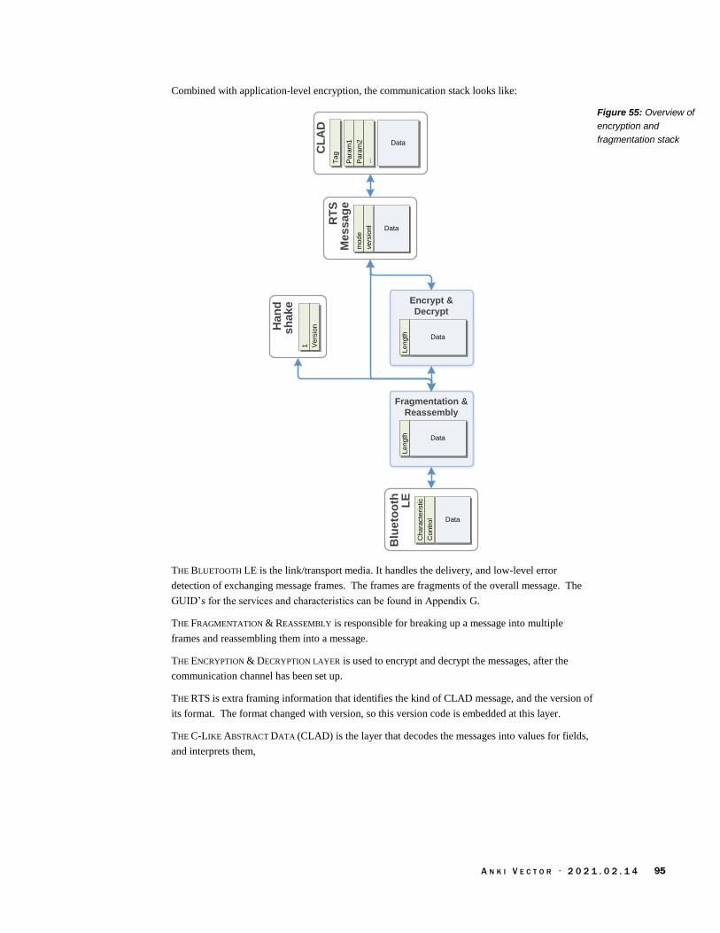
A N K I V E C T O R · 2 0 2 1 . 0 2 . 1 4 95
Combined with application-level encryption, the communication stack looks like:
Fragmentation &
ReassemblyL
en
gth Data
Encrypt &
Decrypt
Le
ng
th Data
Blu
eto
oth
L
EC
ha
racte
ristic
Co
ntr
ol Data
CL
AD
Pa
ram
1
Pa
ram
2 Data
...
Ta
g
Ha
nd
s
ha
ke
1 Ve
rsio
n
RT
S
Me
ss
ag
em
od
e
ve
rsio
nl
Data
THE BLUETOOTH LE is the link/transport media. It handles the delivery, and low-level error
detection of exchanging message frames. The frames are fragments of the overall message. The
GUID’s for the services and characteristics can be found in Appendix G.
THE FRAGMENTATION & REASSEMBLY is responsible for breaking up a message into multiple
frames and reassembling them into a message.
THE ENCRYPTION & DECRYPTION LAYER is used to encrypt and decrypt the messages, after the
communication channel has been set up.
THE RTS is extra framing information that identifies the kind of CLAD message, and the version of
its format. The format changed with version, so this version code is embedded at this layer.
THE C-LIKE ABSTRACT DATA (CLAD) is the layer that decodes the messages into values for fields,
and interprets them,
Figure 55: Overview of
encryption and
fragmentation stack

A N K I V E C T O R · 2 0 2 1 . 0 2 . 1 4 96
39.1. SETTING UP THE COMMUNICATION CHANNEL
It sometimes helps to start with the overall process. This section will walk thru the process,
referring to later sections where detailed information resides.
If you connect for the “first time” – or wish to re-pair with him – put him on the charger and press
the backpack button twice quickly. He’ll display a screen indicating he is getting ready to pair.
If you have already paired the application with Vector, the encryption keys can be reused.
The process to set up a Bluetooth LE communication with Vector is complex. The sequence has
many steps:
Application Vector
Connection Response
Handhake
Handshake
Connection Request
Nonce
Nonce Response
Challenge
Challenge response
Challenge success
1. The application opens Bluetooth LE connection (retrieving the service and characteristics
handles) and subscribes to the “read” characteristic (see Appendix G for the UUID).
2. Vector sends handshake message; which the application receives. The handshake message
structure is given below. The handshake message includes the version of the protocol
supported.
Offset Size Type Parameter Description
0 1 uint8_t type ?
1 4 uint32_t version The version of the protocol/messages to employ
3. The application sends the handshake back
4. Then the Vector will send a connection request, consisting of the public key to use for the
session. The application’s response depends on whether this is a first-time pairing, or a
reuse.
a. First time pairing requires that Vector have already been placed into pairing
mode prior to connecting to Vector. The application keys should be created (see
section 39.3.1 First time pairing above).
b. Reconnection can reuse the public and secret keys, and the encryption and
decryption keys from a prior pairing
5. The application should then send the publicKey in the response
Figure 56: Sequence for
initiating communication
with Vector
Table 36: Parameters
for Handshake message
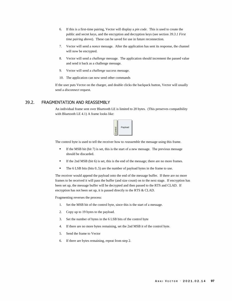
A N K I V E C T O R · 2 0 2 1 . 0 2 . 1 4 97
6. If this is a first-time pairing, Vector will display a pin code. This is used to create the
public and secret keys, and the encryption and decryption keys (see section 39.3.1 First
time pairing above). These can be saved for use in future reconnection.
7. Vector will send a nonce message. After the application has sent its response, the channel
will now be encrypted.
8. Vector will send a challenge message. The application should increment the passed value
and send it back as a challenge message.
9. Vector will send a challenge success message.
10. The application can now send other commands
If the user puts Vector on the charger, and double clicks the backpack button, Vector will usually
send a disconnect request.
39.2. FRAGMENTATION AND REASSEMBLY
An individual frame sent over Bluetooth LE is limited to 20 bytes. (This preserves compatibility
with Bluetooth LE 4.1) A frame looks like: C
on
tro
l Payload
The control byte is used to tell the receiver how to reassemble the message using this frame.
If the MSB bit (bit 7) is set, this is the start of a new message. The previous message
should be discarded.
If the 2nd MSB (bit 6) is set, this is the end of the message; there are no more frames.
The 6 LSB bits (bits 0..5) are the number of payload bytes in the frame to use.
The receiver would append the payload onto the end of the message buffer. If there are no more
frames to be received it will pass the buffer (and size count) on to the next stage. If encryption has
been set up, the message buffer will be decrypted and then passed to the RTS and CLAD. If
encryption has not been set up, it is passed directly to the RTS & CLAD.
Fragmenting reverses the process:
1. Set the MSB bit of the control byte, since this is the start of a message.
2. Copy up to 19 bytes to the payload.
3. Set the number of bytes in the 6 LSB bits of the control byte
4. If there are no more bytes remaining, set the 2nd MSB it of the control byte.
5. Send the frame to Vector
6. If there are bytes remaining, repeat from step 2.
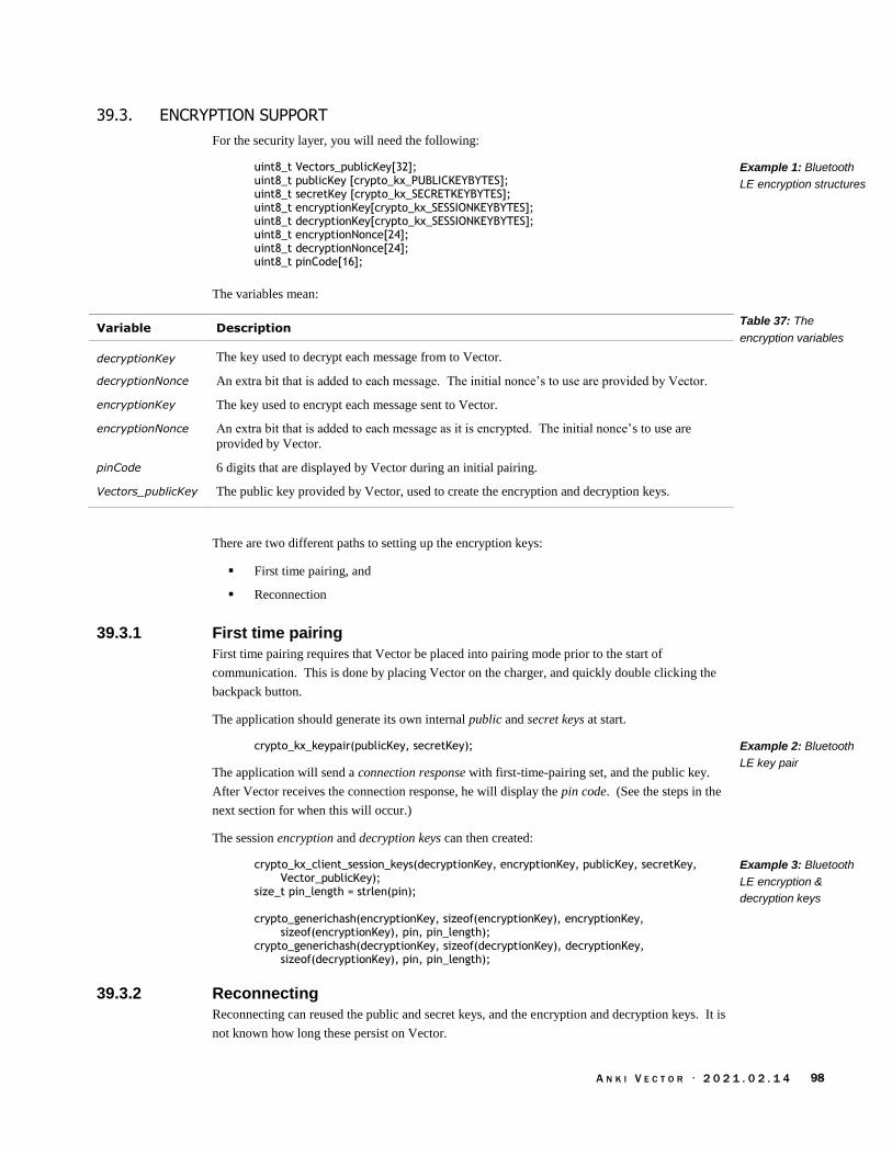
A N K I V E C T O R · 2 0 2 1 . 0 2 . 1 4 98
39.3. ENCRYPTION SUPPORT
For the security layer, you will need the following:
uint8_t Vectors_publicKey[32]; uint8_t publicKey [crypto_kx_PUBLICKEYBYTES]; uint8_t secretKey [crypto_kx_SECRETKEYBYTES]; uint8_t encryptionKey[crypto_kx_SESSIONKEYBYTES]; uint8_t decryptionKey[crypto_kx_SESSIONKEYBYTES]; uint8_t encryptionNonce[24]; uint8_t decryptionNonce[24]; uint8_t pinCode[16];
The variables mean:
Variable Description
decryptionKey The key used to decrypt each message from to Vector.
decryptionNonce An extra bit that is added to each message. The initial nonce’s to use are provided by Vector.
encryptionKey The key used to encrypt each message sent to Vector.
encryptionNonce An extra bit that is added to each message as it is encrypted. The initial nonce’s to use are
provided by Vector.
pinCode 6 digits that are displayed by Vector during an initial pairing.
Vectors_publicKey The public key provided by Vector, used to create the encryption and decryption keys.
There are two different paths to setting up the encryption keys:
First time pairing, and
Reconnection
39.3.1 First time pairing
First time pairing requires that Vector be placed into pairing mode prior to the start of
communication. This is done by placing Vector on the charger, and quickly double clicking the
backpack button.
The application should generate its own internal public and secret keys at start.
crypto_kx_keypair(publicKey, secretKey);
The application will send a connection response with first-time-pairing set, and the public key.
After Vector receives the connection response, he will display the pin code. (See the steps in the
next section for when this will occur.)
The session encryption and decryption keys can then created:
crypto_kx_client_session_keys(decryptionKey, encryptionKey, publicKey, secretKey, Vector_publicKey);
size_t pin_length = strlen(pin); crypto_generichash(encryptionKey, sizeof(encryptionKey), encryptionKey,
sizeof(encryptionKey), pin, pin_length); crypto_generichash(decryptionKey, sizeof(decryptionKey), decryptionKey,
sizeof(decryptionKey), pin, pin_length);
39.3.2 Reconnecting
Reconnecting can reused the public and secret keys, and the encryption and decryption keys. It is
not known how long these persist on Vector.
Example 1: Bluetooth
LE encryption structures
Table 37: The
encryption variables
Example 2: Bluetooth
LE key pair
Example 3: Bluetooth
LE encryption &
decryption keys

A N K I V E C T O R · 2 0 2 1 . 0 2 . 1 4 99
39.3.3 Encrypting and decryption messages
Vector will send a nonce message with the encryption and decryption nonces to employ in
encrypting and decrypting message.
Each received enciphered message can be decrypted from cipher text (cipher, and cipherLen) to the
message buffer (message and messageLen) for further processing:
crypto_aead_xchacha20poly1305_ietf_decrypt(message, &messageLen, NULL, cipher, cipherLen, NULL, 0L, decryptionNonce, decryptionKey);
sodium_increment(decryptionNonce, sizeof decryptionNonce);
Note: the decryptionNonce is incremented each time a message is decrypted.
Each message to be sent can be encrypted from message buffer (message and messageLen) into
cipher text (cipher, and cipherLen) that can be fragmented and sent:
crypto_aead_xchacha20poly1305_ietf_encrypt(cipher, &cipherLen, message, messageLen, NULL, 0L, NULL, encryptionNonce, encryptionKey);
sodium_increment(encryptionNonce, sizeof encryptionNonce);
Note: the encryptionNonce is incremented each time a message is encrypted.
39.4. THE RTS LAYER
There is an extra, pragmatic layer before the messages can be interpreted by the application. The
message has two to three bytes at the header:
Typ
e
Ve
rsio
n Params
Ta
g
The type byte is either 1 or 4. If it is 1 the version number is 1.
If type byte is 4, the version is held in the next byte. (If the type is 1, there is no version
byte).
The next byte is the tag – the value used to interpret the message.
The tag, parameter body, and version are passed to the CLAD layer for interpretation. This is
described in the next section.
Example 4: Decrypting
a Bluetooth LE message
Example 5: Encrypting
a Bluetooth LE message
Figure 57: The format of
an RTS frame

A N K I V E C T O R · 2 0 2 1 . 0 2 . 1 4 100
39.5. FETCHING A LOG
The process to set up a Bluetooth LE communication with Vector is moderately complex. The
sequence has many steps:
Application Vector
Log request
Log response
File download
File download
File download
...
The log request is sent to Vector. In principal this includes a list of the kinds of logs (called filter
names) to be included. In practice, the “filter name” makes no difference.
Vector response, and if there will be a file sent, includes an affirmative and a 32-bit file identifier
used for the file transfer.
Vector zips the log files up (as a tar.bz2 compressed archive) and sends the chunks to the
application. Each chunk has this file identifier. (Conceptually there could be several files in
transfer at a time.)
The file transfer is complete when the packet number matches the packet total.
Figure 58: Sequence for
initiating communication
with Vector

A N K I V E C T O R · 2 0 2 1 . 0 2 . 1 4 101
39.6. A BLE SHELL CONNECTION
The process to set up a Bluetooth LE communication with Vector’s shell is moderately complex.
The sequence has many steps:
Application Vector
BLE Shell connect request
BLE Shell connect response
...
BLE Shell disconnect request
BLE Shell disconnect response
BLE Shell to Server request
BLE Shell to Server response
BLE Shell to Client response
BLE Shell to Client request
The BLE Shell Connect request is sent to Vector. Vector response will include a status code
indicating success or not. If successful a bi-directional stream can be sent.
The client has the option to close the shell connection at any time by sending a BLE Shell
Disconnect request.
Note: The BLE Shell connection requires Version 6 of the BLE protocol to be honored by Vector.
No version of the Vector software has been identified that supports this version.
Figure 59: Sequence for
communication with a
command shell on
Vector

A N K I V E C T O R · 2 0 2 1 . 0 2 . 1 4 102
40. MESSAGE FORMATS
This section describes the format and interpretation of the CLAD messages that go between the
App and Vector. It describes the fields and how they are encoded, etc. Fields that do not have a
fixed location, have no value for their offset. Some fields are only present in later versions of the
protocol. They are marked with the version that they are present in.
Except where otherwise stated:
Requests are from the mobile application to Vector, and responses are Vector to the
application
All are values in little endian order
Request Response Min Version
Application connection id
1F16 2016 4
BLE shell connect 2616 2716 6
BLE shell disconnect 2C16 2D16 6
BLE shell to client 2A16 2B16 6
BLE shell to server 2816 2916 6
Cancel pairing 1016 0
Challenge 0416 0416 0
Challenge success 0516 0
Connect 0116 0216 0
Cloud session 1D16 1E16 3
Disconnect 1116 0
File download 1a16 2
Log 1816 1916 2
Nonce 0316 1216
OTA cancel 1716 2
OTA update 0E16 0F16 0
SDK proxy 2216 2316 5
Response 2116 4
SSH 1516 1616 0
Status 0A16 0B16 0
Versions list 2416 2516 6
WiFi access point 1316 1416 0
WiFi connect 0616 0716 0
WiFi forget 1B16 1C16 3
WiFi IP 0816 0916 0
WiFi scan 0C16 0D16 0
Table 38: Summary of
the commands

A N K I V E C T O R · 2 0 2 1 . 0 2 . 1 4 103
40.1. APPLICATION CONNECTION ID
Assigns a DAS/Analytics id to use with the appication for this Bluetooth LE session.
40.1.1 Request
The parameters of the request body are:
Offset Size Type Parameter Description
0 2 uint16_t id length The length of the id; may be 0
2 varies uint8_t[id length]
id The DAS/Analytics id to associate with the Application
for this Bluetooth LE session.
40.1.2 Response
There is no response.
Table 39: Parameters
for Application
Connection Id request

A N K I V E C T O R · 2 0 2 1 . 0 2 . 1 4 104
40.2. BLE SHELL CONNECT
40.2.1 Request
The request body has no parameters.
40.2.2 Response
The parameters of the response body are:
Offset Size Type Parameter Description
0 1 uint8_t status The error code (or indication of success) for the
command.
40.3. BLE SHELL DISCONNECT
40.3.1 Request
The request body has no parameters.
40.3.2 Response
The parameters of the response body are:
Offset Size Type Parameter Description
0 1 uint8_t status The error code (or indication of success) for the
command.
40.4. BLE SHELL TO CLIENT
40.4.1 Request
The parameters of the request body are:
Offset Size Type Parameter Description
0 2 uint16_t text length The length of the text; may be 0
2 varies uint8_t[text length]
text The text to send to the client from the shell.
40.4.2 Response
The parameters of the response body are:
Offset Size Type Parameter Description
0 1 uint8_t status The error code (or indication of success) for the
command.
Table 40: Parameters
for BLE Shell Connect
response
Table 41: Parameters
for BLE Shell
Disconnect response
Table 42: Parameters
for BLE Shell to Client
request
Table 43: Parameters
for BLE Shell to Client
response

A N K I V E C T O R · 2 0 2 1 . 0 2 . 1 4 105
40.5. BLE SHELL TO SERVER
40.5.1 Request
The parameters of the request body are:
Offset Size Type Parameter Description
0 2 uint16_t text length The length of the text; may be 0
2 varies uint8_t[text length]
text The text to send to the shell (server) from the client.
40.5.2 Response
The parameters of the response body are:
Offset Size Type Parameter Description
0 1 uint8_t status The error code (or indication of success) for the
command.
Table 44: Parameters
for BLE Shell to Server
request
Table 45: Parameters
for BLE Shell to Server
response

A N K I V E C T O R · 2 0 2 1 . 0 2 . 1 4 106
40.6. CANCEL PAIRING
Speculation: this is sent by the application to cancel the pairing process
40.6.1 Request
The command has no parameters.
40.6.2 Response
There is no response.

A N K I V E C T O R · 2 0 2 1 . 0 2 . 1 4 107
40.7. CHALLENGE
This challenge is sent by Vector to the application if he liked the response to a nonce message.
40.7.1 Request
The parameters of the request body are:
Offset Size Type Parameter Description
0 4 uint8_t value The challenge value
The application, when it receives this message, should increment the value and send the response
(a challenge message).
40.7.2 Response
The parameters of the response body are:
Offset Size Type Parameter Description
0 4 uint8_t value The challenge value; this is 1 + the value that was
received.
If Vector accepts the response, he will send a challenge success.
Table 46: Parameters
for challenge request
Table 47: Parameters
for challenge response

A N K I V E C T O R · 2 0 2 1 . 0 2 . 1 4 108
40.8. CHALLENGE SUCCESS
The challenge success is sent by Vector if the challenge response was accepted.
40.8.1 Request
The command has no parameters.
40.8.2 Response
There is no response.

A N K I V E C T O R · 2 0 2 1 . 0 2 . 1 4 109
40.9. CLOUD SESSION
This command is used to request a cloud session.
40.9.1 Command
The parameters of the request body are:
Offset Size Type Parameter Description
0 2 uint16_t session token length
The number of bytes in the session token; may be 0
2 varies uint8_t session token The session token, as received from the cloud server.29
1 uint8_t client name
length
The number of bytes in the client name string; may be 0
version >= 5
varies uint8_t[] client name The client name string. Informational only. The mobile
app uses the name of the mobile device.
version >= 5
1 uint8_t application id
length
The number of bytes in the application id string; may be
0; version >= 5
varies uint8_t[] application id The application id. Informational only. The mobile
uses “companion-app”. version >= 5
40.9.2 Response result
The parameters for the connection response message are:
Offset Size Type Parameter Description
0 1 uint8_t success 0 if failed, otherwise successful
1 1 uint8_t status See Table 50: Cloud status enumeration
2 1 uint16_t client token
GUID length
The number of bytes in the client token GUID; may be 0
varies uint8_t[] client token GUID
The client token GUID. The client token GUID should
be saved for future use.
The cloud status types are:
Index Meaning
0 unknown error
1 connection error
2 wrong account
3 invalid session token
4 authorized as primary
5 authorized as secondary
6 reauthorization
29 https://groups.google.com/forum/#!msg/anki-vector-rooting/YlYQsX08OD4/fvkAOZ91CgAJ https://groups.google.com/forum/#!msg/anki-vector-rooting/XAaBE6e94ek/OdES50PaBQAJ
Table 48: Parameters
for Cloud Session
request
Table 49: Parameters
for Cloud Session
Response
Table 50: Cloud
status enumeration

A N K I V E C T O R · 2 0 2 1 . 0 2 . 1 4 110
40.10. CONNECT
The connect request comes from Vector at the start of a connection. The response is from the
application.
40.10.1 Request
The parameters of the request body are:
Offset Size Type Parameter Description
0 32 uint8_t[32] publicKey The public key for the connection
The application, when it receives this message, should use the public key for the session, and
send a response back.
40.10.2 Response
The parameters for the connection response message are:
Offset Size Type Parameter Description
0 1 uint8_t connectionType See Table 53: Connection types enumeration
1 32 uint8_t[32] publicKey The public key to use for the connection
The connection types are:
Index Meaning
0 first time pairing (requests pin code to be displayed)
1 reconnection
The application sends the response, with its publicKey (see section 39.3 Encryption support). A
“first time pairing” connection type will cause Vector to display a pin code on the screen
If a first time pairing response is sent:
If Vector is not in pairing mode – was not put on his charger and the backpack button
pressed twice, quickly – Vector will respond. Attempting to enter pairing mode now will
cause Vector to send a disconnect request.
If Vector is in pairing mode, Vector will display a pin code on the screen, and send a nonce
message, triggering the next steps of the conversation.
If a reconnection is sent, the application would employ the public and secret keys, and the
encryption and decryption keys from a prior pairing.
Table 51: Parameters
for Connection request
Table 52: Parameters
for Connection
Response
Table 53: Connection
types enumeration

A N K I V E C T O R · 2 0 2 1 . 0 2 . 1 4 111
40.11. DISCONNECT
This may be sent by Vector if there is an error, and it is ending communication. For instance, if
Vector enters pairing mode, it will send a disconnect.
The application may send this to request Vector to close the connection.
40.11.1 Request
The command has no parameters.
40.11.2 Response
There is no response.

A N K I V E C T O R · 2 0 2 1 . 0 2 . 1 4 112
40.12. FILE DOWNLOAD
This command is used to pass chunks of a file from Vector to the application. Files are broken up
into chunks and sent.
40.12.1 Request
There is no direct request.
40.12.2 Response
The parameters of the response body are:
Offset Size Type Parameter Description
0 1 uint8_t status
1 4 uint32_t file id
5 4 uint32_t packet number The chunk within the download
9 4 uint32_t packet total The total number of packets to be sent for this file
download
13 2 uint16_t length The number of bytes to follow (can be 0)
varies uint8_t[length] bytes The bytes of this file chunk
Table 54: Parameters
for File Download
response
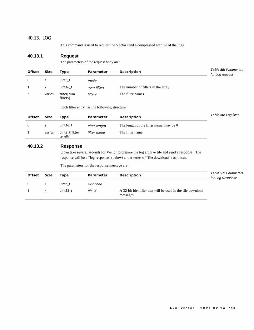
A N K I V E C T O R · 2 0 2 1 . 0 2 . 1 4 113
40.13. LOG
This command is used to request the Vector send a compressed archive of the logs.
40.13.1 Request
The parameters of the request body are:
Offset Size Type Parameter Description
0 1 uint8_t mode
1 2 uint16_t num filters The number of filters in the array
3 varies filter[num filters]
filters The filter names
Each filter entry has the following structure:
Offset Size Type Parameter Description
0 2 uint16_t filter length The length of the filter name; may be 0
2 varies uint8_t[filter length]
filter name The filter name
40.13.2 Response
It can take several seconds for Vector to prepare the log archive file and send a response. The
response will be a “log response” (below) and a series of “file download” responses.
The parameters for the response message are:
Offset Size Type Parameter Description
0 1 uint8_t exit code
1 4 uint32_t file id A 32-bit identifier that will be used in the file download
messages.
Table 55: Parameters
for Log request
Table 56: Log filter
Table 57: Parameters
for Log Response

A N K I V E C T O R · 2 0 2 1 . 0 2 . 1 4 114
40.14. NONCE
A nonce is sent by Vector after he has accepted the application’s key. The application is to send a
response.
40.14.1 Request
The parameters for the nonce request message are:
Offset Size Type Parameter Description
0 24 uint8_t[24] toVectorNonce The nonce to use for sending stuff to Vector
24 24 uint8_t[24] toAppNonce The nonce for receiving stuff from Vector
40.14.2 Response
After receiving a nonce, if the application is in first-time pairing the application should send a
response, with a value of 3.
Offset Size Type Parameter Description
0 1 uint8_t connection tag This is always 3
After the response has been sent, the channel will now be encrypted. If vector likes the response,
he will send a challenge message.
Table 58: Parameters
for Nonce request
Table 59: Parameters
for Nonce response

A N K I V E C T O R · 2 0 2 1 . 0 2 . 1 4 115
40.15. OTA UPDATE
This command is used to request the Vector download software from a given server URL.
40.15.1 Request
The parameters of the request body are:
Offset Size Type Parameter Description
0 1 uint8_t length The length of the URL; may be 0
1 varies uint8_t[length] URL The URL string
40.15.2 Response
The response will be one or more “OTA response” indicating the status of the update, or errors.
Status codes >= 200 indicate that the update process has completed. The update has completed the
download when the current number of bytes match the expected number of bytes.
The parameters for the response message are:
Offset Size Type Parameter Description
0 1 uint8_t status See Table 62: OTA status enumeration
1 8 uint64_t current The number of bytes downloaded
9 8 uint64_t expected The number of bytes expected to be downloaded
The OTA status codes are:
Status Meaning
0 idle
1 unknown
2 in progress
3 complete
4 rebooting
5 error
200… Status codes from the update-engine. See Appendix D, Table 606: OTA
update-engine status codes.
Note: the status codes 200 and above are from the update-engine, and are given in Appendix D.
Table 60: Parameters
for OTA request
Table 61: Parameters
for OTA Response
Table 62: OTA status
enumeration

A N K I V E C T O R · 2 0 2 1 . 0 2 . 1 4 116
40.16. RESPONSE
This message will be sent on the event of an error. Primarily if the session is not cloud authorized
and the command requires it.
Offset Size Type Parameter Description
0 1 uint16_t code 0 if not cloud authorized, otherwise authorized
1 1 uint8_t length The number of bytes in the string that follows.
varies uint8_t [length] text A text error message.
Table 63: Parameters
for Response
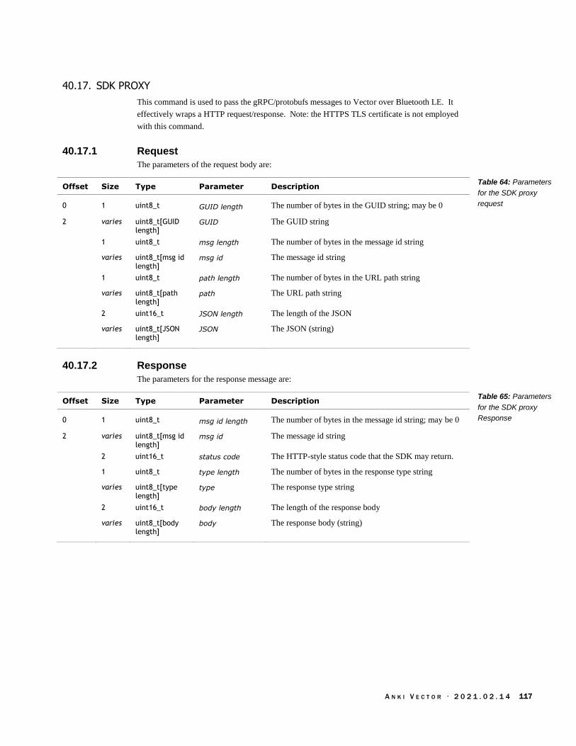
A N K I V E C T O R · 2 0 2 1 . 0 2 . 1 4 117
40.17. SDK PROXY
This command is used to pass the gRPC/protobufs messages to Vector over Bluetooth LE. It
effectively wraps a HTTP request/response. Note: the HTTPS TLS certificate is not employed
with this command.
40.17.1 Request
The parameters of the request body are:
Offset Size Type Parameter Description
0 1 uint8_t GUID length The number of bytes in the GUID string; may be 0
2 varies uint8_t[GUID length]
GUID The GUID string
1 uint8_t msg length The number of bytes in the message id string
varies uint8_t[msg id length]
msg id The message id string
1 uint8_t path length The number of bytes in the URL path string
varies uint8_t[path length]
path The URL path string
2 uint16_t JSON length The length of the JSON
varies uint8_t[JSON length]
JSON The JSON (string)
40.17.2 Response
The parameters for the response message are:
Offset Size Type Parameter Description
0 1 uint8_t msg id length The number of bytes in the message id string; may be 0
2 varies uint8_t[msg id length]
msg id The message id string
2 uint16_t status code The HTTP-style status code that the SDK may return.
1 uint8_t type length The number of bytes in the response type string
varies uint8_t[type length]
type The response type string
2 uint16_t body length The length of the response body
varies uint8_t[body length]
body The response body (string)
Table 64: Parameters
for the SDK proxy
request
Table 65: Parameters
for the SDK proxy
Response
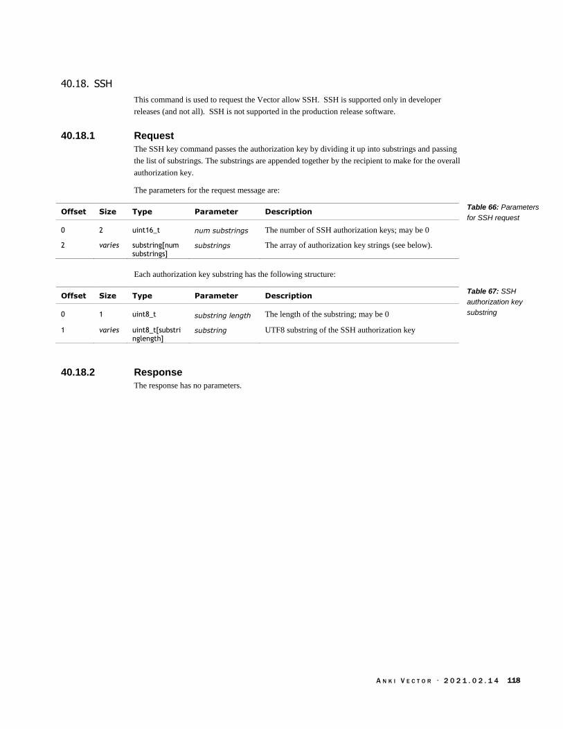
A N K I V E C T O R · 2 0 2 1 . 0 2 . 1 4 118
40.18. SSH
This command is used to request the Vector allow SSH. SSH is supported only in developer
releases (and not all). SSH is not supported in the production release software.
40.18.1 Request
The SSH key command passes the authorization key by dividing it up into substrings and passing
the list of substrings. The substrings are appended together by the recipient to make for the overall
authorization key.
The parameters for the request message are:
Offset Size Type Parameter Description
0 2 uint16_t num substrings The number of SSH authorization keys; may be 0
2 varies substring[num substrings]
substrings The array of authorization key strings (see below).
Each authorization key substring has the following structure:
Offset Size Type Parameter Description
0 1 uint8_t substring length The length of the substring; may be 0
1 varies uint8_t[substringlength]
substring UTF8 substring of the SSH authorization key
40.18.2 Response
The response has no parameters.
Table 66: Parameters
for SSH request
Table 67: SSH
authorization key
substring
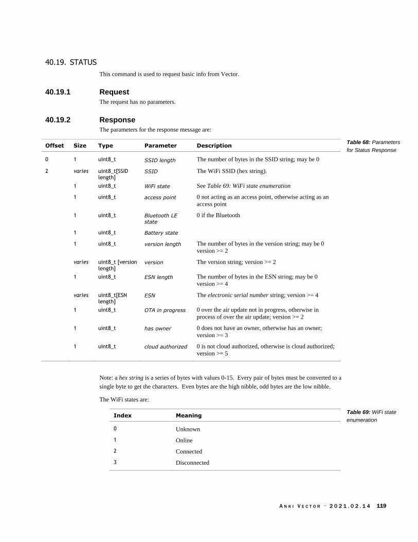
A N K I V E C T O R · 2 0 2 1 . 0 2 . 1 4 119
40.19. STATUS
This command is used to request basic info from Vector.
40.19.1 Request
The request has no parameters.
40.19.2 Response
The parameters for the response message are:
Offset Size Type Parameter Description
0 1 uint8_t SSID length The number of bytes in the SSID string; may be 0
2 varies uint8_t[SSID length]
SSID The WiFi SSID (hex string).
1 uint8_t WiFi state See Table 69: WiFi state enumeration
1 uint8_t access point 0 not acting as an access point, otherwise acting as an
access point
1 uint8_t Bluetooth LE
state
0 if the Bluetooth
1 uint8_t Battery state
1 uint8_t version length The number of bytes in the version string; may be 0
version >= 2
varies uint8_t [version length]
version The version string; version >= 2
1 uint8_t ESN length The number of bytes in the ESN string; may be 0
version >= 4
varies uint8_t[ESN length]
ESN The electronic serial number string; version >= 4
1 uint8_t OTA in progress 0 over the air update not in progress, otherwise in
process of over the air update; version >= 2
1 uint8_t has owner 0 does not have an owner, otherwise has an owner;
version >= 3
1 uint8_t cloud authorized 0 is not cloud authorized, otherwise is cloud authorized;
version >= 5
Note: a hex string is a series of bytes with values 0-15. Every pair of bytes must be converted to a
single byte to get the characters. Even bytes are the high nibble, odd bytes are the low nibble.
The WiFi states are:
Index Meaning
0 Unknown
1 Online
2 Connected
3 Disconnected
Table 68: Parameters
for Status Response
Table 69: WiFi state
enumeration

A N K I V E C T O R · 2 0 2 1 . 0 2 . 1 4 120
40.20. VERSIONS LIST
40.20.1 Request
The request body has no parameters.
40.20.2 Response
The parameters of the response body are:
Offset Size Type Parameter Description
0 2 uint16_t length The length of the array; may be 0
2 varies uint16_t[length]
versions An array of version numbers.
Table 70: Parameters
for Version List
response

A N K I V E C T O R · 2 0 2 1 . 0 2 . 1 4 121
40.21. WIFI ACCESS POINT
This command is used to request that the Vector act as a WiFi access point. This command
requires that a “cloud session” have been successfully started first (see section 40.9 Cloud session).
If successful, Vector will provide a WiFi Access Point with an SSID that matches his robot name.
40.21.1 Request
The parameters of the request body are:
Offset Size Type Parameter Description
0 1 uint8_t enable 0 to disable the WiFi access point, 1 to enable it
40.21.2 Response
If the Bluetooth LE session is not cloud authorized a “response” message will be sent with this
error. Otherwise the WiFi Access Point response message will be sent.
The parameters for the response message are:
Offset Size Type Parameter Description
0 1 uint8_t enabled 0 if the WiFi access point is disabled, otherwise enabled
1 1 uint8_t SSID length The number of bytes in the SSID string; may be 0
2 varies uint8_t[SSID length]
SSID The WiFi SSID (hex string)
1 uint8_t password length The number of bytes in the password string; may be 0
varies uint8_t [password length]
password The WiFi password
Table 71: Parameters
for WiFi Access Point
request
Table 72: Parameters
for WiFi Access Point
Response
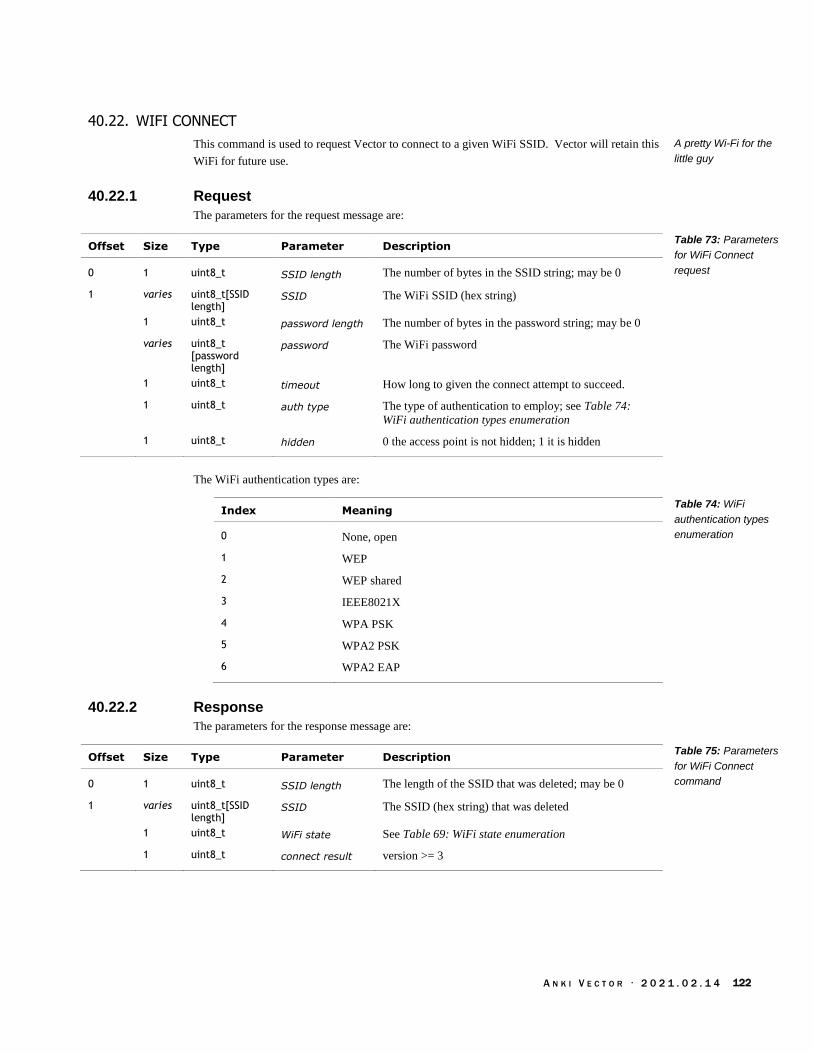
A N K I V E C T O R · 2 0 2 1 . 0 2 . 1 4 122
40.22. WIFI CONNECT
This command is used to request Vector to connect to a given WiFi SSID. Vector will retain this
WiFi for future use.
40.22.1 Request
The parameters for the request message are:
Offset Size Type Parameter Description
0 1 uint8_t SSID length The number of bytes in the SSID string; may be 0
1 varies uint8_t[SSID length]
SSID The WiFi SSID (hex string)
1 uint8_t password length The number of bytes in the password string; may be 0
varies uint8_t [password length]
password The WiFi password
1 uint8_t timeout How long to given the connect attempt to succeed.
1 uint8_t auth type The type of authentication to employ; see Table 74:
WiFi authentication types enumeration
1 uint8_t hidden 0 the access point is not hidden; 1 it is hidden
The WiFi authentication types are:
Index Meaning
0 None, open
1 WEP
2 WEP shared
3 IEEE8021X
4 WPA PSK
5 WPA2 PSK
6 WPA2 EAP
40.22.2 Response
The parameters for the response message are:
Offset Size Type Parameter Description
0 1 uint8_t SSID length The length of the SSID that was deleted; may be 0
1 varies uint8_t[SSID length]
SSID The SSID (hex string) that was deleted
1 uint8_t WiFi state See Table 69: WiFi state enumeration
1 uint8_t connect result version >= 3
A pretty Wi-Fi for the
little guy
Table 73: Parameters
for WiFi Connect
request
Table 74: WiFi
authentication types
enumeration
Table 75: Parameters
for WiFi Connect
command
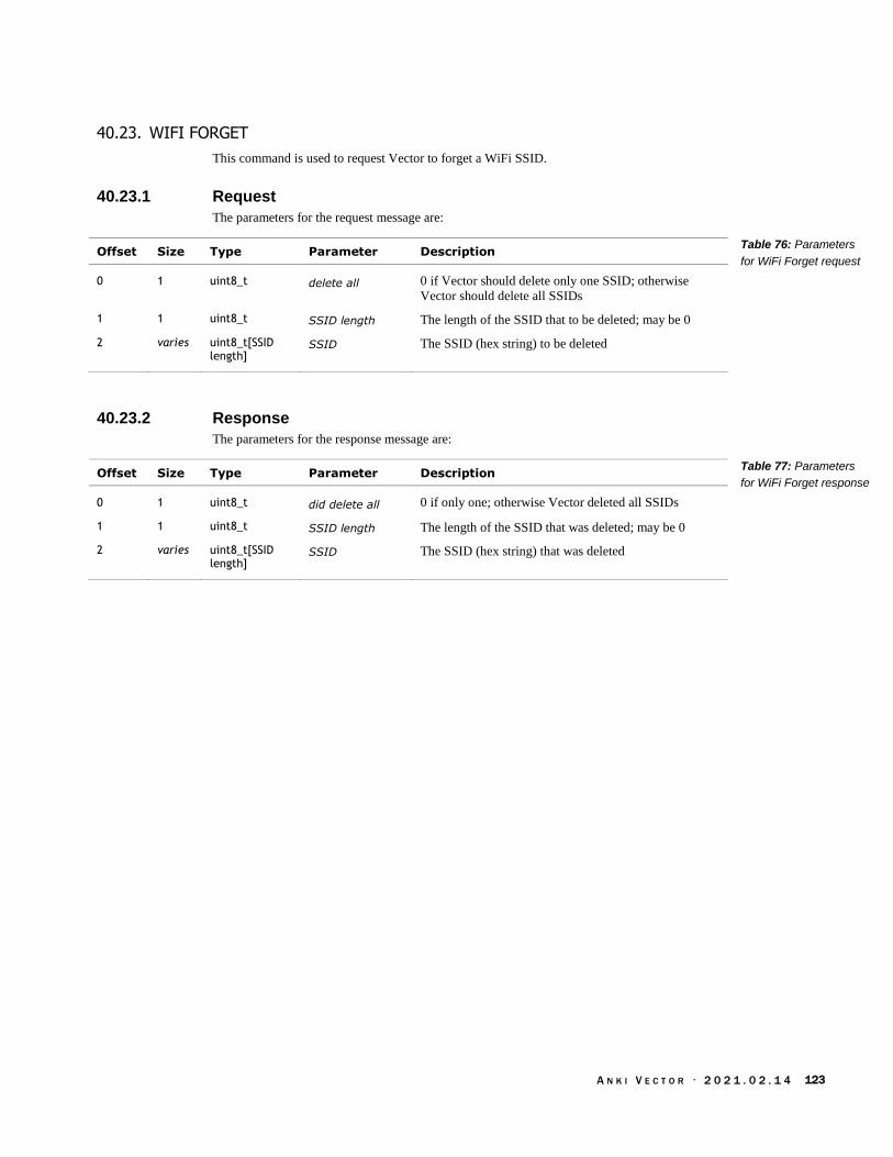
A N K I V E C T O R · 2 0 2 1 . 0 2 . 1 4 123
40.23. WIFI FORGET
This command is used to request Vector to forget a WiFi SSID.
40.23.1 Request
The parameters for the request message are:
Offset Size Type Parameter Description
0 1 uint8_t delete all 0 if Vector should delete only one SSID; otherwise
Vector should delete all SSIDs
1 1 uint8_t SSID length The length of the SSID that to be deleted; may be 0
2 varies uint8_t[SSID length]
SSID The SSID (hex string) to be deleted
40.23.2 Response
The parameters for the response message are:
Offset Size Type Parameter Description
0 1 uint8_t did delete all 0 if only one; otherwise Vector deleted all SSIDs
1 1 uint8_t SSID length The length of the SSID that was deleted; may be 0
2 varies uint8_t[SSID length]
SSID The SSID (hex string) that was deleted
Table 76: Parameters
for WiFi Forget request
Table 77: Parameters
for WiFi Forget response

A N K I V E C T O R · 2 0 2 1 . 0 2 . 1 4 124
40.24. WIFI IP ADDRESS
This command is used to request Vector’s WiFi IP address.
40.24.1 Request
The request has no parameters
40.24.2 Response
The parameters for the response message are:
Offset Size Type Parameter Description
0 1 uint8_t has IPv4 0 if Vector doesn’t have an IPv4 address; other it does
1 1 uint8_t has IPv6 0 if Vector doesn’t have an IPv6 address; other it does
2 4 uint8_t[4] IPv4 address Vector’s IPv4 address
6 32 uint8_t[16] IPv6 address Vector’s IPv6 address
Table 78: Parameters
for WiFi IP Address
response

A N K I V E C T O R · 2 0 2 1 . 0 2 . 1 4 125
40.25. WIFI SCAN
This command is used to request Vector to scan for WiFi access points.
40.25.1 Request
The command has no parameters.
40.25.2 Response
The response lists the Wi-Fi access points Vector can find. The parameters for the response
message are:
Offset Size Type Parameter Description
0 1 uint8_t status code
1 1 uint8_t num entries The number of access points in the array below
2 varies AP[num entries]
access points The array of access points
Each access point has the following structure:
Offset Size Type Parameter Description
0 1 uint8_t auth type The type of authentication to employ; see Table 74:
WiFi authentication types enumeration
1 1 uint8_t signal strength The number of bars, 0..4
2 1 uint8_t SSID length The length of the SSID string
3 varies uint8_t[SSID length]
SSID The SSID (hex string)
1 uint8_t hidden 0 not hidden, 1 hidden; version >= 2
1 uint8_t provisioned 0 not provisioned, 1 provisioned; version>= 3
finding hot signals in
Vectors area
Table 79: Parameters
for WiFi scan response
Table 80: Parameters
access point structure

A N K I V E C T O R · 2 0 2 1 . 0 2 . 1 4 126
CHAPTER 14
Cube Bluetooth LE
Communication
Protocol
This chapter describes communication protocol to talk with the Cube.
The kinds of activities that can be performed
The interaction sequences
The characteristics.
41. CUBE COMMUNICATION PROTOCOL OVERVIEW
Vector can be “paired” with a cube – or he’ll automatically pair with the first cube he finds during
setup – and will treat this as his preferred cube. If he is unable can’t connect with his preferred
cube, he falls back to connecting the first cube found in the area while playing.
Vector manages the link with the cube, and data is sent and received using Bluetooth LE
characteristics. Vector may send values, fetch values from the Cube, or ask to be sent values when
they change.
When Bluetooth LE is in an unconnected state, it sends out advertisements at a regular interval, but
not too speedy. When Vector connects with the cube, it doesn’t open a stream of continuous bits.
Instead, it negotiates a new interval that is appropriate for speed of interaction, distance, and
battery life.
41.1. SENDING THE FIRMWARE APPLICATION
The Cube has a boot-loader built in, but the application firmware is held in SRAM. It has to be
downloaded to the cube by Vector. The Vector application is determines if the application is
already present by reading the application firmware version. The application download is done
with a sequence like:
Vector Cube
Version request
Version response
...
OTA download
OTA download
Paul m Brett
Figure 60: Sequence for
sending the Cube
firmware
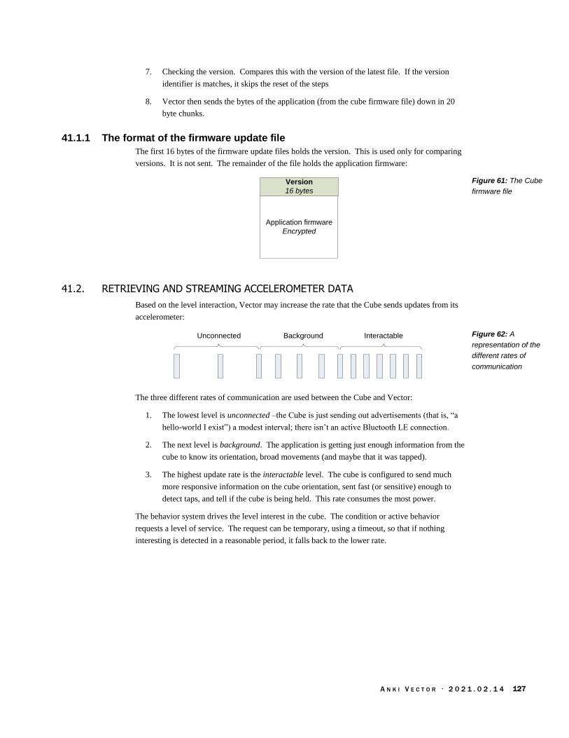
A N K I V E C T O R · 2 0 2 1 . 0 2 . 1 4 127
7. Checking the version. Compares this with the version of the latest file. If the version
identifier is matches, it skips the reset of the steps
8. Vector then sends the bytes of the application (from the cube firmware file) down in 20
byte chunks.
41.1.1 The format of the firmware update file
The first 16 bytes of the firmware update files holds the version. This is used only for comparing
versions. It is not sent. The remainder of the file holds the application firmware:
Version
16 bytes
Application firmware
Encrypted
41.2. RETRIEVING AND STREAMING ACCELEROMETER DATA
Based on the level interaction, Vector may increase the rate that the Cube sends updates from its
accelerometer:
Unconnected InteractableBackground
The three different rates of communication are used between the Cube and Vector:
1. The lowest level is unconnected –the Cube is just sending out advertisements (that is, “a
hello-world I exist”) a modest interval; there isn’t an active Bluetooth LE connection.
2. The next level is background. The application is getting just enough information from the
cube to know its orientation, broad movements (and maybe that it was tapped).
3. The highest update rate is the interactable level. The cube is configured to send much
more responsive information on the cube orientation, sent fast (or sensitive) enough to
detect taps, and tell if the cube is being held. This rate consumes the most power.
The behavior system drives the level interest in the cube. The condition or active behavior
requests a level of service. The request can be temporary, using a timeout, so that if nothing
interesting is detected in a reasonable period, it falls back to the lower rate.
Figure 61: The Cube
firmware file
Figure 62: A
representation of the
different rates of
communication

A N K I V E C T O R · 2 0 2 1 . 0 2 . 1 4 128
42. CHARACTERISTIC MESSAGE FORMATS
This section describes the format and interpretation of the characteristics that go between the
Vector and the Cube. It describes the fields and how they are encoded, etc.
All multi-byte values are in little endian order
See Appendix G for the GUIDs for the characteristics
42.1. STRUCTURES
These are the data structures used within the messages.
42.1.1 Accelerometer data
The structure for the accelerometer data is:
Offset Size Type Parameter Description
0 2 int16_t X The measurement (in milli-gs) along the X-axis.
2 2 int16_t Y The measurement (in milli-gs) along the Y-axis.
4 2 int16_t Z The measurement (in milli-gs) along the Z-axis.
42.1.2 LED data
The structure for the LED data is:
Offset Size Type Parameter Description
0 1 uint8_t index Sequential index, starting at 0. This is the step in the
light sequence pattern to play.
1 1 uint8_t red The red-channel color value
2 1 uint8_t green The green-channel color value
3 1 uint8_t blue The blue-channel color value
4 1 uint8_t alpha The alpha-channel color value. Usually 0
5 1 uint8_t duration The amount of time, in milliseconds(?), to show the
color before proceeding to the next step.
This structure is related to the ones given Chapter 23 section 103 Cube lights Animation for cube
light animation. Probably separate for each of the LEDs.
42.2. LED CONTROL
The parameters of the LED control characteristic are:
Offset Size Type Parameter Description
0 1 uint8_t trigger 1 set light information
1 18 LED data[3] LED data The LED settings for each step
Paul m Brett
Table 81: Parameters
for accelerometer
structure
Table 82: Parameters
for LED control structure
Table 83: Parameters
for accelerometer
characteristic

A N K I V E C T O R · 2 0 2 1 . 0 2 . 1 4 129
The parameters of the LED control characteristic are:
Offset Size Type Parameter Description
0 1 uint8_t trigger 0 Trigger s or starts it
1 1 uint8_t[4] sequence Id The sequence index to start with for that LED.
42.3. APPLICATION VERSION
This is used to retrieve the version string for the application. It is used to determine if the
application is present in the Cube, or needs to be sent to the Cube. The parameters of the
application version are:
Offset Size Type Parameter Description
0 varies char[] version Empty if there is no application. Otherwise, the version
of the application. The version is also the date and time
of the firmware build.
42.4. BATTERY AND ACCELEROMETER CHARACTERISTIC
The parameters of the battery and accelerometer characteristic are:
Offset Size Type Parameter Description
0 2 uint16_t battery battery ADC value
2 18 Accel_t[3] accelerometer Accelerometer samples
42.5. OTA DOWNLOAD
This characteristic is used to send the firmware. These are sent as a series of 20 byte chunks. The
application firmware is encrypted and will be decrypted by the boot-loader.
42.6. REFERENCES & RESOURCES
Brett, Paul, Communicating with vectors cube
https://forums.anki.com/t/communicating-with-vectors-cube/43042
Paul digs into emulating the Vector’s cube and identifies elements of the protocol. This
chapter was adapted from this information.
Table 84: Parameters
for accelerometer
characteristic
Table 85: Parameters
for version characteristic
Table 86: Parameters
for accelerometer
characteristic

A N K I V E C T O R · 2 0 2 1 . 0 2 . 1 4 130
CHAPTER 15
The HTTPS based
API
This chapter describes the communication with Vector via the local HTTPS.
Note: the information in this chapter comes from the protobuf specification files in the python
SDK, from the SDK itself, and some analysis of the mobile application. All quotes (unless
otherwise indicated) are from the SDK.
43. OVERVIEW OF THE SDK HTTPS API
The descriptions below30 give the JSON keys, and their value format. It is implemented as
gRPC/protobufs interaction over HTTP. (Anki has frequently said that the SDK included code (as
python) with the protobuf spec so that others could use their own preferred implementation
language.) Each command is requested by POST-ing the request structure to the given relative
URL (relative to Vector’s address or local network name) and interpreting the returned body as the
response structure.
The HTTPS header should include
Bearer BASE64KEY
Content-Type: application/json
(The JSON request is posted in the body)
43.1. SDK MESSAGE GROUPINGS
The major groups of messages here are:
Accessories and custom objects
Actions and behaviors – setting the current priority and cancelling actions
Alexa configuration – configuring Vector to use Alexa’s services
Audio – playing sounds on Vector, and submitting text to speech
Battery – the current state of charge
Connection – authenticating with the remote servers to allow access to Vector, connection
management, event stream, and end-point version info
Cube – commands to manage and interact with the cube
Diagnostics – checking the connection with the cloud, and uploading log information
Display – display images on Vector’s LCD
30 The protocol was specified in Google Protobuf.

A N K I V E C T O R · 2 0 2 1 . 0 2 . 1 4 131
Faces (of people, not Vector’s face) – changing the name of a face, deleting a face
Features and entitlements – the features that are enabled (or disabled)
Image processing – Getting a video stream, and enabling (or disabling) video processing
steps, retrieving & changing the camera exposure settings.
Interactions with objects (outside of the cube)
JDocs, the JSON document storage interface
Map and Navigation
Motion Control
Motion Sensing – how Vector senses that he is moving
Onboarding
Photos – commands to access (and delete) photographs and their thumbnails
Settings and Preferences
Software Updates, used to update Vector’s software – operating system, applications,
assets, etc.

A N K I V E C T O R · 2 0 2 1 . 0 2 . 1 4 132
44. COMMON ELEMENTS
The enumerations and structures in this section are common to many commands.
44.1. ENUMERATIONS
44.1.1 ResultCode
The ResultCode enumeration has the following named values:
Name Value Description
ERROR_UPDATE_IN_PROGRESS 1 The settings could not be applied; there is already
another update to the settings in process.
SETTINGS_ACCEPTED 0 The settings were successfully saved.
44.1.2 RobotStatus
The RobotStatus is a bit mask used to indicate what Vector is doing, and the status of his controls.
It is used in the RobotState message. The enumeration has the following named bits (any number
may be set). Note that some bits have two names; the second name is one employed by Anki’s
python SDK.
Name Value Description
ROBOT_STATUS_NONE 0000016
ROBOT_STATUS_IS_MOVING
ROBOT_STATUS_ARE_MOTORS_MOVING 0000116 This bit is set “if Vector is currently moving any of
his motors (head, arm or wheels/treads).”
ROBOT_STATUS_IS_CARRYING_BLOCK 0000216 This bit is set “if Vector is currently carrying a
block.”
ROBOT_STATUS_IS_PICKING_OR_PLACING ROBOT_STATUS_IS_DOCKING_TO_MARKER
0000416 This bit is set “if Vector has seen a marker and is
actively heading toward it (for example his charger
or cube).”
ROBOT_STATUS_IS_PICKED_UP 0000816 This bit is set “if Vector is currently picked up (in
the air),” being held or is on his side. Vector “uses
the IMU data to determine if the robot is not on a
stable surface with his treads down.” If Vector is
not on stable surface (with his treads down), this bit
is set.
ROBOT_STATUS_IS_BUTTON_PRESSED 0001016 This bit is set “if Vector's button is pressed.”
ROBOT_STATUS_IS_FALLING 0002016 This bit is set “if Vector is currently falling.”
ROBOT_STATUS_IS_ANIMATING 0004016 This bit is set “if Vector is currently playing an
animation.”
ROBOT_STATUS_IS_PATHING 0008016 This bit is set “if Vector is currently traversing a
path.”
ROBOT_STATUS_LIFT_IN_POS 0010016 This bit is set “if Vector's arm is in the desired
position.” It is clear “if still trying to move it
there.”
ROBOT_STATUS_HEAD_IN_POS 0020016 This bit is set “if Vector's head is in the desired
position.” It is clear “if still trying to move there.”
ROBOT_STATUS_CALM_POWER_MODE 0040016 This bit is set “if Vector is in calm power mode.
Table 87: ResultCode
Enumeration
Table 88: RobotStatus
Enumeration

A N K I V E C T O R · 2 0 2 1 . 0 2 . 1 4 133
Calm power mode is generally when Vector is
sleeping or charging.”
ROBOT_STATUS_IS_BATTERY_DISCONNECT
ED 0080016 Not officially defined. This bit is set if the battery
is disconnected.
ROBOT_STATUS_IS_ON_CHARGER 0100016 This bit is set “if Vector is currently on the
charger.” (As determined by the charging
electronics.) Note: Vector may be on the charger
without charging.
ROBOT_STATUS_IS_CHARGING 0200016 This bit is set “if Vector is currently charging.”
ROBOT_STATUS_CLIFF_DETECTED 0400016 This bit is set “if Vector detected a cliff using any
of his four cliff sensors.”
ROBOT_STATUS_ARE_WHEELS_MOVING 0800016 This bit is set “if Vector's wheels/treads are
currently moving.”
ROBOT_STATUS_IS_BEING_HELD 1000016 This bit is set “if Vector is being held.”
Note: ROBOT_STATUS_IS_PICKED_UP will also be
set when this bit is set.
Vector “uses the IMU to look for tiny motions that
suggest the robot is actively being held in
someone's hand.” This is used to distinguish from
other cases, such as falling, on its side, etc.
ROBOT_STATUS_IS_MOTION_DETECTED
ROBOT_STATUS_IS_ROBOT_MOVING 2000016 This bit is set “if Vector is in motion. This includes
any of his motors (head, arm, wheels/tracks) and if
he is being lifted, carried, or falling.”
ROBOT_STATUS_IS_BATTERY_OVERHEATED 4000016 Not official defined. This bit is set if Vector’s
battery temperature is considered too hot.
reserved 8000016 reserved
ROBOT_STATUS_ENCODERS_DISABLED 10000016 Not officially defined. This bit is set if Vector has
turned off the motor encoders. This is done to save
power when the motors are idle.
ROBOT_STATUS_ENCODER_HEAD_INVALID 20000016 Not officially defined. This bit is set if Vector the
encoder for the head is not valid.
ROBOT_STATUS_ENCODER_LIFT_INVALID 40000016 Not officially defined. This bit is set if Vector the
encoder for the head is not valid.
ROBOT_STATUS_IS_BATTERY_LOW 100000016 Not officially defined. This bit is set if Vector
battery voltage is critically low; if not on a charger,
Vector will power down.
ROBOT_STATUS_IS_SHUTDOWN_IMMINENT 200000016 Not officially defined. This bit is set if the body
board will turn off power very soon. This may be
due to excessive temperature or battery under
voltage.
Note: the RobotStatus is maintained by vic-robot

A N K I V E C T O R · 2 0 2 1 . 0 2 . 1 4 134
44.2. STRUCTURES
44.2.1 CladPoint
The CladPoint is used to represent a 2D rectilinear point on an image or in the 2D map. It has the
following fields:
Field Type Units Description
x float pixels The x-coordinate of the point
y float pixels The y-coordinate of the point
44.2.2 CladRect
The CladRect is used to represent a 2D rectilinear rectangle on an image. It has the following
fields:
Field Type Units Description
height float pixels The height of the rectangle
width float pixels The width of the rectangle
x_top_left float pixels The x-coordinate of the top-left corner of the
rectangle within the image.
y_top_left float pixels The y-coordinate of the top-left corner of the
rectangle within the image.
44.2.3 PoseStruct
The PoseStruct is used to represent a 3D rectilinear point and orientation on the map. It has the
following fields:
Field Type Units Description
origin_id uint32 Which version of the map this pose is in (0 for
none or unknown). See Chapter 19 for a
description of the mapping origin id.
q0 float Part of the rotation quaternion
q1 float Part of the rotation quaternion
q2 float Part of the rotation quaternion
q3 float Part of the rotation quaternion
x float mm The x coordinate
y float mm The y coordinate
z float mm The z coordinate
44.2.4 ResponseStatus
The ResponseStatus is “a shared response message sent back as part of most requests. This will
indicate the generic state of the request.” It has the following fields:
Table 89: CladPoint
JSON structure
Table 90:
CladRectangle JSON
structure
Table 91: PoseStruct
JSON structure

A N K I V E C T O R · 2 0 2 1 . 0 2 . 1 4 135
Field Type Units Description
code StatusCode “The generic status code to give high-level insight
into the progress of a given message.”
Table 92:
ResponseStatus JSON
structure

A N K I V E C T O R · 2 0 2 1 . 0 2 . 1 4 136
The StatusCode is used to indicate state of the request.
Name Value Description
UNKNOWN 0
RESPONSE_RECEIVED 1 “The message has completed as expected.”
REQUEST_PROCESSING 2 “The message has been sent to the robot.”
OK 3 “The message has been handled successfully at the
interface level.”
FORBIDDEN 100 “The user was not authorized.”
NOT_FOUND 101 “The requested attribute was not found.”
ERROR_UPDATE_IN_PROGRESS 102 “Currently updating values from another call.”
45. ACCESSORIES AND CUSTOM OBJECTS
This section describes the objects that Vector can see and track in his map. Specialized accessories
– the charger and cube – are broken out into their own sections.
See also section 53 Cube and section 59 Interactions with Objects
You too can create custom objects for Vector to… at least see and perceive. Maybe even love.
There are four kinds of custom objects that you can define:
A fixed, unmarked cube-shaped object. The object is in a fixed position and orientation,
and it can’t be observed (since it is unmarked). So there won’t be any events related to this
object. “This could be used to make Vector aware of objects and know to plot a path
around them.”
A flat wall with only a front side,
A cube, with the same marker on each side.
A box with different markers on each side.
A note about object id’s: The object id may change: “a cube disconnecting and reconnecting it's
removed and then re-added to robot's internal world model which results in a new ID.”
The client should employ a timer for each potential visual object. If there isn’t an “object
observed” event received in the time period, it should be assumed “that Vector can no longer see
an object.”
45.1. ENUMERATIONS
The CustomObjectMarker enumerates the marker symbols
The CustomType refers to the one of the 20 possible custom objects that can be defined
The ObjectFamily is an older, now deprecated method, of enumerating the kind of object
(as in, charger, light cube, wall, box, or custom cube).
The ObjectType enumeration is the preferred method of enumerating the kinds of objects
Table 93: StatusCode
Enumeration

A N K I V E C T O R · 2 0 2 1 . 0 2 . 1 4 137
45.1.1 CustomObjectMarker
The CustomObjectMarker is used represent the marker symbol used. The symbols are predefined,
with the images that Vector recognizes included in the SDK. The enumeration has the following
named values:
Name Value Description
CUSTOM_MARKER_UNKNOWN 0
CUSTOM_MARKER_CIRCLES_2 1
CUSTOM_MARKER_CIRCLES_3 2
CUSTOM_MARKER_CIRCLES_4 3
CUSTOM_MARKER_CIRCLES_5 4
CUSTOM_MARKER_DIAMONDS_2 5
CUSTOM_MARKER_DIAMONDS_3 6
CUSTOM_MARKER_DIAMONDS_4 7
CUSTOM_MARKER_DIAMONDS_5 8
CUSTOM_MARKER_HEXAGONS_2 9
CUSTOM_MARKER_HEXAGONS_3 10
CUSTOM_MARKER_HEXAGONS_4 11
CUSTOM_MARKER_HEXAGONS_5 12
CUSTOM_MARKER_TRIANGLES_2 13
CUSTOM_MARKER_TRIANGLES_3 14
CUSTOM_MARKER_TRIANGLES_4 15
CUSTOM_MARKER_TRIANGLES_5 16
CUSTOM_MARKER_COUNT 16
Table 94:
CustomObjectMarker
Enumeration

A N K I V E C T O R · 2 0 2 1 . 0 2 . 1 4 138
45.1.2 CustomType
The CustomType is used to represent the identifier of object that a symbol is attached to. The
enumeration has the following named values:
Name Value Description
INVALID_CUSTOM_TYPE 0
CUSTOM_TYPE_00 1
CUSTOM_TYPE_01 2
CUSTOM_TYPE_02 3
CUSTOM_TYPE_03 4
CUSTOM_TYPE_04 5
CUSTOM_TYPE_05 6
CUSTOM_TYPE_06 7
CUSTOM_TYPE_07 8
CUSTOM_TYPE_08 9
CUSTOM_TYPE_09 10
CUSTOM_TYPE_10 11
CUSTOM_TYPE_11 12
CUSTOM_TYPE_12 13
CUSTOM_TYPE_13 14
CUSTOM_TYPE_14 15
CUSTOM_TYPE_15 16
CUSTOM_TYPE_16 17
CUSTOM_TYPE_17 18
CUSTOM_TYPE_18 19
CUSTOM_TYPE_19 20
CUSTOM_TYPE_COUNT 20
Table 95: CustomType
Enumeration

A N K I V E C T O R · 2 0 2 1 . 0 2 . 1 4 139
45.1.3 ObjectFamily
The ObjectFamily is a deprecated method used to represent the type of object that a symbol is
attached to. ObjectType should be used instead, where possible. The enumeration has the
following named values:
Name Value Description
INVALID_FAMILY 0 This value represents a kind of object that is not
properly set.
UNKNOWN_FAMILY 1 This value is used when there is an object, but its
kind is not known.
BLOCK 2 This is the identifier used for blocks/cubs other
than the companion-cube
LIGHT_CUBE 3 This is the identifier used for the companion-cube
CHARGER 4 This is the identifier used for the home charging
station.
CUTSTOM_OBJECT 7 This is the identifier used for as custom object
definition.
OBJECT_FAMILY_COUNT 7
45.1.4 ObjectType
The ObjectType is used represent the type of object that a symbol is attached to. The enumeration
has the following named values:
Name Value Description
INVALID_OBJECT 0 This value represents an object id used when there
isn’t an object associated.
UNKNOWN_OBJECT 1 This value is used when there is an object, but it is
not recognized.
BLOCK_LIGHTCUBE1 2 This is the identifier used for the companion-cube
CHARGER_BASIC 6 This is the identifier used for the home charging
station.
FIRST_CUSTOM_OBJECT_TYPE 15 The custom objects all have types greater than or
equal to this.
Table 96: ObjectType
Enumeration
Table 97: ObjectType
Enumeration

A N K I V E C T O R · 2 0 2 1 . 0 2 . 1 4 140
45.2. EVENTS
These are the events that are sent to inform the application of an objects state (and availability).
45.2.1 ObjectEvent
The ObjectEvent event is sent (see Event message) when the state of an object has changed. The
structure has one (and only one) of the following fields:
Field Type Description
cube_connection_lost CubeConnectionLost This event is sent when cube no longer is connected
via Bluetooth LE.
robot_observed_object RobotObservedObject This even is sent the object is visually seen by
Vector.
object_available ObjectAvailable This event is sent when cube a Bluetooth LE
connection to the cube is established.
object_connection_state ObjectConnectionState The information about the Bluetooth LE identity of
the cube, and whether is connected (or not).
object_moved ObjectMoved The object has changed position.
object_stopped_moving ObjectStoppedMoving The object had change position previously, but has
now come to rest.
object_tapped ObjectTapped The cube was tapped.
object_up_axis_changed ObjectUpAxisChanged The object was rotated and has a new upward face.
45.2.2 ObjectAvailable
The ObjectAvailable event is sent (see section 45.2.1 ObjectEvent) when Vector has received
Bluetooth LE advertisements from the object (cube).
See also section 53.2.2 CubeConnectionLost
This event structure has the following fields:
Field Type Units Description
factory_id string The identifier for the cube. This is built into the
cube.
45.2.3 ObjectConnectionState
The ObjectConnectedState event is to “indicate that a cube has connected or disconnected to the
robot. This message will be sent for any connects or disconnects regardless of whether it
originated from us or underlying robot behavior.”
See also section 53.2.2 CubeConnectionLost
Table 98: ObjectEvent
JSON structure
Table 99:
ObjectAvailable JSON
structure
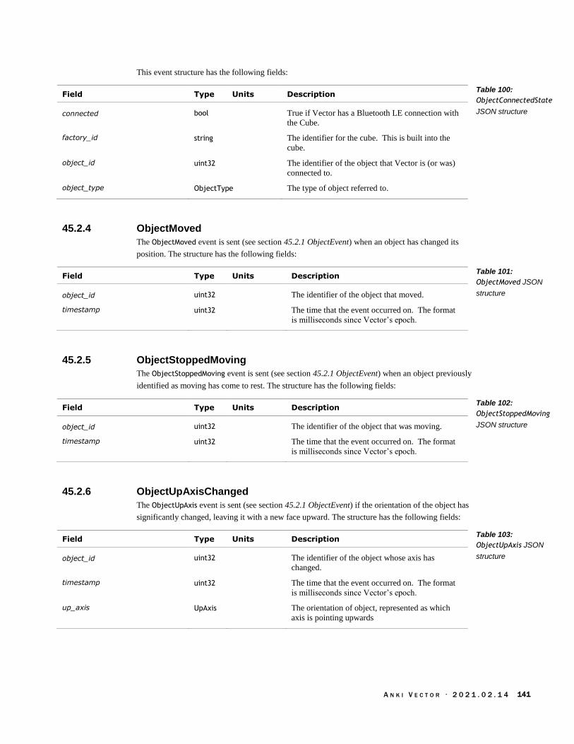
A N K I V E C T O R · 2 0 2 1 . 0 2 . 1 4 141
This event structure has the following fields:
Field Type Units Description
connected bool True if Vector has a Bluetooth LE connection with
the Cube.
factory_id string The identifier for the cube. This is built into the
cube.
object_id uint32 The identifier of the object that Vector is (or was)
connected to.
object_type ObjectType The type of object referred to.
45.2.4 ObjectMoved
The ObjectMoved event is sent (see section 45.2.1 ObjectEvent) when an object has changed its
position. The structure has the following fields:
Field Type Units Description
object_id uint32 The identifier of the object that moved.
timestamp uint32 The time that the event occurred on. The format
is milliseconds since Vector’s epoch.
45.2.5 ObjectStoppedMoving
The ObjectStoppedMoving event is sent (see section 45.2.1 ObjectEvent) when an object previously
identified as moving has come to rest. The structure has the following fields:
Field Type Units Description
object_id uint32 The identifier of the object that was moving.
timestamp uint32 The time that the event occurred on. The format
is milliseconds since Vector’s epoch.
45.2.6 ObjectUpAxisChanged
The ObjectUpAxis event is sent (see section 45.2.1 ObjectEvent) if the orientation of the object has
significantly changed, leaving it with a new face upward. The structure has the following fields:
Field Type Units Description
object_id uint32 The identifier of the object whose axis has
changed.
timestamp uint32 The time that the event occurred on. The format
is milliseconds since Vector’s epoch.
up_axis UpAxis The orientation of object, represented as which
axis is pointing upwards
Table 100:
ObjectConnectedState
JSON structure
Table 101:
ObjectMoved JSON
structure
Table 102:
ObjectStoppedMoving
JSON structure
Table 103:
ObjectUpAxis JSON
structure

A N K I V E C T O R · 2 0 2 1 . 0 2 . 1 4 142
The UpAxis is used represent the orientation of an object. The enumeration has the following
named values:
Name Value Description
INVALID_AXIS 0 The orientation of the object is not known.
X_NEGATIVE 1 The positive direction along the body’s x-axis is
upward.
X_POSITIVE 2 The negative direction along the body’s x-axis is
upward.
Y_NEGATIVE 3 The positive direction along the body’s y-axis is
upward.
Y_POSITIVE 4 The negative direction along the body’s y-axis is
upward.
Z_NEGATIVE 5 The positive direction along the body’s z-axis is
upward.
Z_POSITIVE 6 The negative direction along the body’s z-axis is
upward.
NUM_AXES 7
45.2.7 RobotObservedObject
The RobotObservedObject event is sent when “an object with [the] specified ID/Type was seen at a
particular location in the image and the world.” This event structure has the following fields:
Field Type Units Description
img_rect CladRect The position of the object within the vision image.
is_active uint32
object_family ObjectFamily Deprecated. “Use ObjectType instead to reason
about groupings of objects.”
object_id int32 The identifier of the object that has been seen.
Note that this is signed (int32 instead of uint32) for
internal compatibility reasons.
object_type ObjectType The type of object referred to.
pose PoseStruct The observed pose of this object. Optional.
timestamp uint32 The time that the object was most recently
observed. The format is milliseconds since
Vector’s epoch.
top_face_orientation_rad float radians “Angular distance from the current reported up
axis. “ “absolute orientation of top face, iff
isActive==true”
Table 104: UpAxis
Enumeration
Table 105:
RobotObservedObject
JSON structure

A N K I V E C T O R · 2 0 2 1 . 0 2 . 1 4 143
45.3. CREATE FIXED CUSTOM OBJECT
This command “creates a permanent custom [cube-shaped] object instance in the robot's world”
except this object has “no markers associated with it.” The object “will remain in the specified
pose as an obstacle forever (or until deleted).” The object can’t be observed, and won’t create any
events related to being observed. The fixed, custom object can “be used to make Vector aware of
objects and know to plot a path around them.”
Post: “/v1/create_fixed_custom_object”
45.3.1 Request
The CreateFixedCustomObjectRequest structure has the following fields:
Field Type Units Description
pose PoseStruct The position and orientation of this object.
x_size_mm float mm The size of the object that the marker symbol is on,
along the x-axis.
y_size_mm float mm The size of the object that the marker symbol is on,
along the y-axis.
z_size_mm float mm The size of the object that the marker symbol is on,
along the z-axis.
45.3.2 Response
The CreateFixedCustomObjectResponse structure has the following fields:
Field Type Description
object_id uint32 The object identifier assigned to this object.
status ResponseStatus A generic status of whether the request was able
to be carried out, or an error code indicating why
it was unable to be carried out.
Table 106:
CreateFixedCustomObje
ctRequest JSON
structure
Table 107:
CreateFixedCustomObje
ctResponse JSON
structure
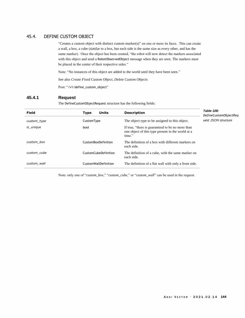
A N K I V E C T O R · 2 0 2 1 . 0 2 . 1 4 144
45.4. DEFINE CUSTOM OBJECT
“Creates a custom object with distinct custom marker(s)” on one or more its faces. This can create
a wall, a box, a cube (similar to a box, but each side is the same size as every other, and has the
same marker). Once the object has been created, “the robot will now detect the markers associated
with this object and send a RobotObservedObject message when they are seen. The markers must
be placed in the center of their respective sides.”
Note: “No instances of this object are added to the world until they have been seen.”
See also Create Fixed Custom Object, Delete Custom Objects
Post: “/v1/define_custom_object”
45.4.1 Request
The DefineCustomObjectRequest structure has the following fields:
Field Type Units Description
custom_type CustomType The object type to be assigned to this object.
is_unique bool If true, “there is guaranteed to be no more than
one object of this type present in the world at a
time.”
custom_box CustomBoxDefinition The definition of a box with different markers on
each side.
custom_cube CustomCubeDefinition The definition of a cube, with the same marker on
each side.
custom_wall CustomWallDefinition The definition of a flat wall with only a front side.
Note: only one of “custom_box,” “custom_cube,” or “custom_wall” can be used in the request.
Table 108:
DefineCustomObjectReq
uest JSON structure

A N K I V E C T O R · 2 0 2 1 . 0 2 . 1 4 145
The CustomBoxDefinition “defines a custom object of the given size with the given markers
centered on each side.” The structure has the following fields:
Field Type Units Description
marker_back CustomObjectMarker The marker symbol used on the back surface of the
box. This marker must be unique (not used by any
of the other side’s on this box or in any other
shape).
marker_bottom CustomObjectMarker The marker symbol used on the bottom surface of
the box. This marker must be unique (not used by
any of the other side’s on this box or in any other
shape).
marker_front CustomObjectMarker The marker symbol used on the front surface of the
box. This marker must be unique (not used by any
of the other side’s on this box or in any other
shape).
marker_left CustomObjectMarker The marker symbol used on the left-hand side of
the box. This marker must be unique (not used by
any of the other side’s on this box or in any other
shape).
marker_right CustomObjectMarker The marker symbol used on the right-hand side of
the box This marker must be unique (not used by
any of the other side’s on this box or in any other
shape).
marker_top CustomObjectMarker The marker symbol used on the top surface of the
box. This marker must be unique (not used by any
of the other side’s on this box or in any other
shape).
marker_height_mm float mm The height of the marker symbol.
marker_width_mm float mm The width of the marker symbol.
x_size_mm float mm The size of the object, along the x-axis, that the
marker symbol is on.
y_size_mm float mm The size of the object, along the y-axis, that the
marker symbol is on.
z_size_mm float mm The width of the object, along the z-axis, that the
marker symbol is on.
The CustomCubeDefinition “defines a custom cube of the given size.” The structure has the
following fields:
Field Type Units Description
marker CustomObjectMarker The marker symbol used on all of the cube
surfaces; “the same marker [must] be centered on
all faces.”
marker_height_mm float mm The height of the marker symbol
marker_width_mm float mm The width of the marker symbol
size_mm float mm The height, width, and depth of the object that the
marker symbol is on.
Table 109:
CustomBoxDefinition
JSON structure
Table 110:
CustomCubeDefinition
JSON structure

A N K I V E C T O R · 2 0 2 1 . 0 2 . 1 4 146
The CustomWallDefinition “defines a custom wall of the given height and width... The wall's
thickness is assumed to be 1cm (and thus there are no markers on its left, right, top, or bottom).”
The structure has the following fields:
Field Type Units Description
marker CustomObjectMarker The marker symbol used on the wall surfaces; “the
same marker centered on both sides (front and
back)”
marker_height_mm float mm The height of the marker symbol
marker_width_mm float mm The width of the marker symbol
height_mm float mm The height of the object that the marker symbol is
on.
width_mm float mm The width of the object that the marker symbol is
on.
45.4.2 Response
The DefineCustomObjectResponse type has the following fields:
Field Type Description
status ResponseStatus A generic status of whether the request was able
to be carried out, or an error code indicating why
it was unable to be carried out.
success bool True if the thumbnail was successfully retrieved;
otherwise there was an error.
Table 111:
CustomWallDefinition
JSON structure
Table 112:
DefineCustomObjectRe
sponse JSON structure

A N K I V E C T O R · 2 0 2 1 . 0 2 . 1 4 147
45.5. DELETE CUSTOM OBJECTS
This command “causes the robot to forget about custom objects it currently knows about.” All
custom objects that match the given pattern are removed.
Post: “/v1/delete_custom_objects”
45.5.1 Request
The DeleteCustomObjectsRequest type has the following fields:
Field Type Description
mode CustomObjectDeletionMode The kind of custom objects to remove.
The CustomObjectDeletionMode is used to specify which kinds of custom objects should be deleted
from the internal database. The enumeration has the following named values:
Name Value Description
DELETION_MASK_UNKNOWN 0
DELETION_MASK_FIXED_CUSTO
M_OBJECTS 1 Delete the custom objects that are “fixed” – the
ones that don't have any marker symbols.
DELETION_MASK_CUSTOM_MARKER_OBJECTS
2 Delete the objects with marker symbols.
DELETION_MASK_ARCHETYPES 3 Deletes everything but the fixed objects and their
marker symbols.
45.5.2 Response
The DeleteCustomObjectsResponse type has the following fields:
Field Type Description
status ResponseStatus A generic status of whether the request was able
to be carried out, or an error code indicating why
it was unable to be carried out.
Table 113:
DeleteCustomObjectsRe
quest JSON structure
Table 114:
CustomObjectDeletionM
ode Enumeration
Table 115:
DeleteCustomObjectsRe
sponse JSON structure
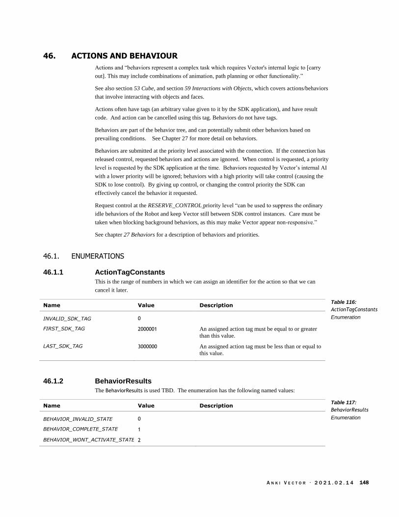
A N K I V E C T O R · 2 0 2 1 . 0 2 . 1 4 148
46. ACTIONS AND BEHAVIOUR
Actions and “behaviors represent a complex task which requires Vector's internal logic to [carry
out]. This may include combinations of animation, path planning or other functionality.”
See also section 53 Cube, and section 59 Interactions with Objects, which covers actions/behaviors
that involve interacting with objects and faces.
Actions often have tags (an arbitrary value given to it by the SDK application), and have result
code. And action can be cancelled using this tag. Behaviors do not have tags.
Behaviors are part of the behavior tree, and can potentially submit other behaviors based on
prevailing conditions. See Chapter 27 for more detail on behaviors.
Behaviors are submitted at the priority level associated with the connection. If the connection has
released control, requested behaviors and actions are ignored. When control is requested, a priority
level is requested by the SDK application at the time. Behaviors requested by Vector’s internal AI
with a lower priority will be ignored; behaviors with a high priority will take control (causing the
SDK to lose control). By giving up control, or changing the control priority the SDK can
effectively cancel the behavior it requested.
Request control at the RESERVE_CONTROL priority level “can be used to suppress the ordinary
idle behaviors of the Robot and keep Vector still between SDK control instances. Care must be
taken when blocking background behaviors, as this may make Vector appear non-responsive.”
See chapter 27 Behaviors for a description of behaviors and priorities.
46.1. ENUMERATIONS
46.1.1 ActionTagConstants
This is the range of numbers in which we can assign an identifier for the action so that we can
cancel it later.
Name Value Description
INVALID_SDK_TAG 0
FIRST_SDK_TAG 2000001 An assigned action tag must be equal to or greater
than this value.
LAST_SDK_TAG 3000000 An assigned action tag must be less than or equal to
this value.
46.1.2 BehaviorResults
The BehaviorResults is used TBD. The enumeration has the following named values:
Name Value Description
BEHAVIOR_INVALID_STATE 0
BEHAVIOR_COMPLETE_STATE 1
BEHAVIOR_WONT_ACTIVATE_STATE 2
Table 116:
ActionTagConstants
Enumeration
Table 117:
BehaviorResults
Enumeration

A N K I V E C T O R · 2 0 2 1 . 0 2 . 1 4 149
46.2. EVENTS
46.2.1 FeatureStatus
The FeatureStatus status event is sent as Vector’s behavior focus changes. The structure has the
following fields:
Field Type Description
feature_name string The current active behaviour (feature). See
Appendix I, table Table 637: The AI behaviour
features for a list and description.
source string Where the direction to do this behavior came from:
“Voice”, “App”, “AI”, “Unknown”. Voice is for
responses to voice commands and intents; “App” is
for application submitted intents; AI is behaviors
initiated by the high-level AI.
Note: for Vector-OS feature flags, see section 57 Features & Entitlements.
46.2.2 StimulationInfo
The StimulationInfo event is used report events that impact Vector’s emotion state and overall
stimulation level. The structure has the following fields:
Field Type Units Description
accel float mm/sec2 The acceleration at the time of the stimulation.
emotion_events string[] The list of event names related to the emotion.
The names of emotion events and their description
can be found in Appendix K Table 641: The
emotion event names. Optional.
max_value float The minimum stimulation value. Typically 1
min_value float The maximum stimulation value. Typically 0
value float The stimulation value after applying the events.
value_before_event float The stimulation value before the event(s).
“matches value if there were no emotion events”
velocity float mm/sec The speed at the time of the stimulation.
Table 118:
FeatureStatus JSON
structure
Table 119:
StimulationInfo JSON
structure

A N K I V E C T O R · 2 0 2 1 . 0 2 . 1 4 150
46.3. STRUCTURES
46.3.1 ActionResults
“The possible results of running an action.” The structure has the following fields:
Field Type Description
code ActionResultCode The results
The ActionResultCode is used to provide “the possible results of running an action.”
Name Value Description
ACTION_RESULT_SUCCESS 0 “Action completed successfully.”
ACTION_RESULT_RUNNING 16777216 “Action is still running.”
ACTION_RESULT_CANCELLED_WHILE_RUNNING
33554432 “Action was cancelled by SDK request”
NOT_STARTED 33554433 “Initial state of an Action to indicate it has not yet
started.”
ABORT 50331648 “Action aborted itself (e.g. had invalid attributes, or
a runtime failure).”
ANIM_ABORTED 50331649 “Animation Action aborted itself (e.g. there was an
error playing the animation).”
BAD_MARKER 50331650 “There was an error related to vision markers.”
BAD_MESSAGE_TAG 50331651 “There was a problem related to a subscribed or
unsupported message tag”
BAD_OBJECT 50331652 “There was a problem with the Object ID provided
(e.g. there is no Object with that ID).”
BAD_POSE 50331653 “There was a problem with the Pose provided.”
BAD_TAG 50331654 “The SDK-provided tag was bad.”
CHARGER_UNPLUGGED_ABORT 50331655 “Vector is on the charger but cannot sense the
contacts. Charger may be unplugged.”
CLIFF_ALIGN_FAILED_TIMEOUT 50331656
CLIFF_ALIGN_FAILED_NO_TURNING 50331657
CLIFF_ALIGN_FAILED_OVER_TURNING 50331658
CLIFF_ALIGN_FAILED_NO_WHITE 50331659
CLIFF_ALIGN_FAILED_STOPPED 50331660
FAILED_SETTING_CALIBRATION 50331661 “Shouldn't occur outside of factory.”
FOLLOWING_PATH_BUT_NOT_TRAVERSING 50331662 “There was an error following the planned path.”
INTERRUPTED 50331663 “The action was interrupted by another Action or
Behavior.”
INVALID_OFF_TREADS_STATE 50331664 “The robot ended up in an "off treads state" not
valid for this action (e.g. the robot was placed on its
back while executing a turn).”
MISMATCHED_UP_AXIS 50331665 “The Up Axis of a carried object doesn't match the
desired placement pose.”
Table 120:
ActionResults JSON
structure
Table 121:
ActionResultCode
Enumeration
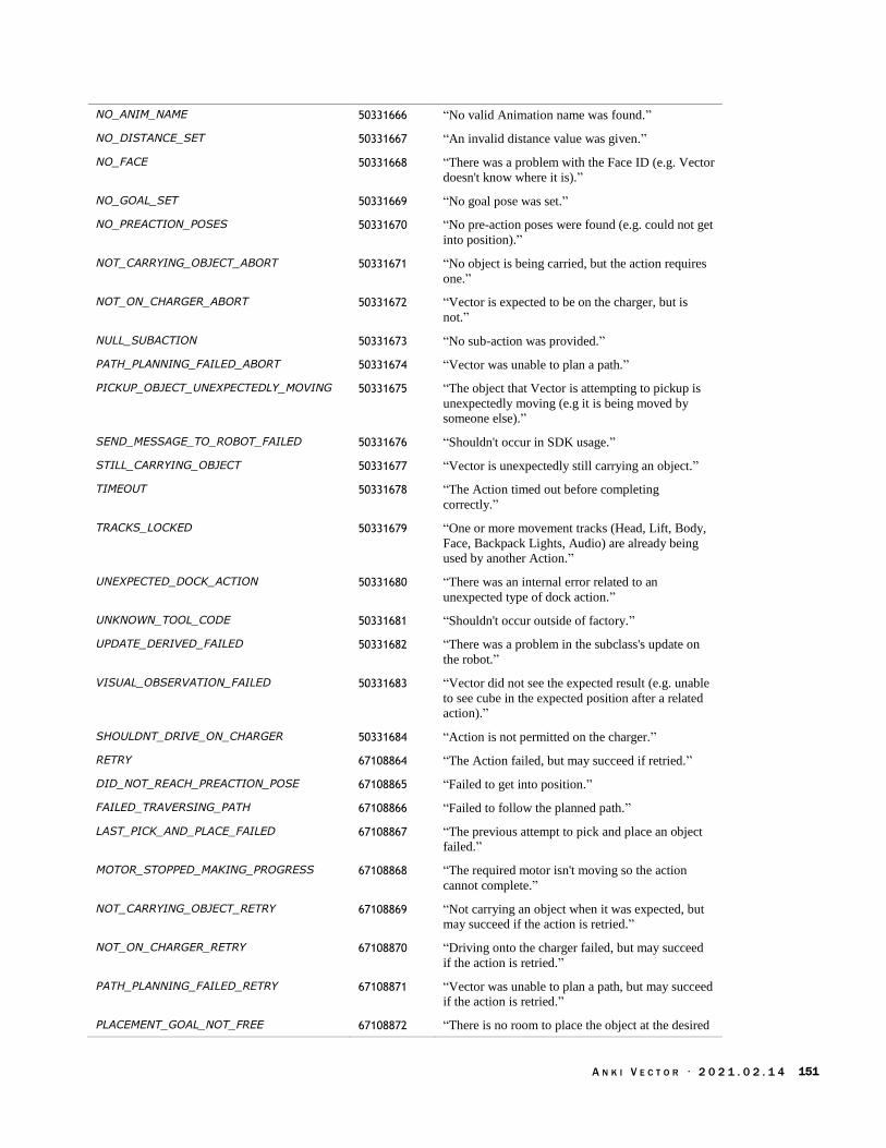
A N K I V E C T O R · 2 0 2 1 . 0 2 . 1 4 151
NO_ANIM_NAME 50331666 “No valid Animation name was found.”
NO_DISTANCE_SET 50331667 “An invalid distance value was given.”
NO_FACE 50331668 “There was a problem with the Face ID (e.g. Vector
doesn't know where it is).”
NO_GOAL_SET 50331669 “No goal pose was set.”
NO_PREACTION_POSES 50331670 “No pre-action poses were found (e.g. could not get
into position).”
NOT_CARRYING_OBJECT_ABORT 50331671 “No object is being carried, but the action requires
one.”
NOT_ON_CHARGER_ABORT 50331672 “Vector is expected to be on the charger, but is
not.”
NULL_SUBACTION 50331673 “No sub-action was provided.”
PATH_PLANNING_FAILED_ABORT 50331674 “Vector was unable to plan a path.”
PICKUP_OBJECT_UNEXPECTEDLY_MOVING 50331675 “The object that Vector is attempting to pickup is
unexpectedly moving (e.g it is being moved by
someone else).”
SEND_MESSAGE_TO_ROBOT_FAILED 50331676 “Shouldn't occur in SDK usage.”
STILL_CARRYING_OBJECT 50331677 “Vector is unexpectedly still carrying an object.”
TIMEOUT 50331678 “The Action timed out before completing
correctly.”
TRACKS_LOCKED 50331679 “One or more movement tracks (Head, Lift, Body,
Face, Backpack Lights, Audio) are already being
used by another Action.”
UNEXPECTED_DOCK_ACTION 50331680 “There was an internal error related to an
unexpected type of dock action.”
UNKNOWN_TOOL_CODE 50331681 “Shouldn't occur outside of factory.”
UPDATE_DERIVED_FAILED 50331682 “There was a problem in the subclass's update on
the robot.”
VISUAL_OBSERVATION_FAILED 50331683 “Vector did not see the expected result (e.g. unable
to see cube in the expected position after a related
action).”
SHOULDNT_DRIVE_ON_CHARGER 50331684 “Action is not permitted on the charger.”
RETRY 67108864 “The Action failed, but may succeed if retried.”
DID_NOT_REACH_PREACTION_POSE 67108865 “Failed to get into position.”
FAILED_TRAVERSING_PATH 67108866 “Failed to follow the planned path.”
LAST_PICK_AND_PLACE_FAILED 67108867 “The previous attempt to pick and place an object
failed.”
MOTOR_STOPPED_MAKING_PROGRESS 67108868 “The required motor isn't moving so the action
cannot complete.”
NOT_CARRYING_OBJECT_RETRY 67108869 “Not carrying an object when it was expected, but
may succeed if the action is retried.”
NOT_ON_CHARGER_RETRY 67108870 “Driving onto the charger failed, but may succeed
if the action is retried.”
PATH_PLANNING_FAILED_RETRY 67108871 “Vector was unable to plan a path, but may succeed
if the action is retried.”
PLACEMENT_GOAL_NOT_FREE 67108872 “There is no room to place the object at the desired

A N K I V E C T O R · 2 0 2 1 . 0 2 . 1 4 152
destination.”
PICKUP_OBJECT_UNEXPECTEDLY_NOT_MOVING
67108873 “The object that Vector thought he was lifting
didn't start moving, so he must have missed.”
STILL_ON_CHARGER 67108874 “Vector failed to drive off the charger.”
UNEXPECTED_PITCH_ANGLE 67108875 “Vector's pitch is at an unexpected angle for the
Action.”

A N K I V E C T O R · 2 0 2 1 . 0 2 . 1 4 153
46.4. BEHAVIOR CONTROL AND ASSUME BEHAVIOR CONTROL
These commands are used to setup the ability to submit actions and behaviors into Vector’s AI
system. This control is needed “to be able to directly control Vector's motors, override his screen,
play an animation, etc.”
The request specifies a priority level. After control is granted, Vector’s AI will suppress internal
behaviors with a lower priority. When a behavior is commanded by the SDK, it will be associated
with the priority level selected here. Note: the priority level is represented by a number where
lower values represent higher priorities, and higher values represent lower priorities. See Chapter
28 for a detailed description of behavior priorities.
There are two entry points: AssumeBehaviorControl and BehaviorControl. Both employ the same
request and response message structures. The response is a stream that includes information when
the control was acquired, and lost.
Post: “/v1/assume_behavior_control”
46.4.1 Request
The BehaviorControlRequest is used to request control of Vector’s behavior stream, and to release
it. This structure includes one (and only one) of the following fields:
Field Type Description
control_release {} This is used to when the application is releasing
control back to Vector; the value is an empty
dictionary.
control_request ControlRequest This is used when the application is requesting
control of Vector; see below for a description.
The ControlRequest is used to request control of the behavior system at a given priority. This
structure has the following fields:
Field Type Description
priority Priority This is the priority level that should be employed
for requested behaviors; internal behaviors with a
priority lower than this will be suppressed.
The Priority enumeration has the following named priority level values:
Name Value Description
UNKNOWN 0 “Unknown priority. Used for versions that doesn’t
understand old priority levels.”
OVERRIDE_BEHAVIORS 10 “Highest priority level. Suppresses most automatic
physical reactions, use with caution.”
DEFAULT 20 “Normal priority level. Directly under mandatory
physical reactions.”
RESERVE_CONTROL 30 This priority level is “used to disable idle
behaviors.” It is intended to “enable long-running
SDK control between script executions. Not.. for
regular behavior control.”
Table 122:
BehaviorControlRequest
JSON structure
Table 123:
ControlRequest JSON
structure
Table 124: Priority level
Enumeration

A N K I V E C T O R · 2 0 2 1 . 0 2 . 1 4 154
46.4.2 Response
The response is a stream of BehaviorControlResponse structures that includes information when the
control was acquired, and lost. This structure includes one (and only one) of the following fields:
Field Type Units Description
control_granted_response {} The application is now in control of the behavior
stream and is “free to run any actions and
behaviors they like. Until a ControlLostResponse
is received, they are directly in control of Vector's
behavior system.”
control_lost_event {} “This informs the user that they lost control of the
behavior system... to a higher priority behavior.”
“This control can be regained through another”
BehaviorControlRequest.
keep_alive KeepAlivePing “Used by Vector to verify the connection is still
alive.”
reserved_control_lost_event {} The “behavior system lock has been lost to
another connection.” “This control can be
regained through another”
BehaviorControlRequest. This is sent when the
SDK is at RESERVE_CONTROL priority level.
Table 125:
BehaviorControlRespons
e JSON structure
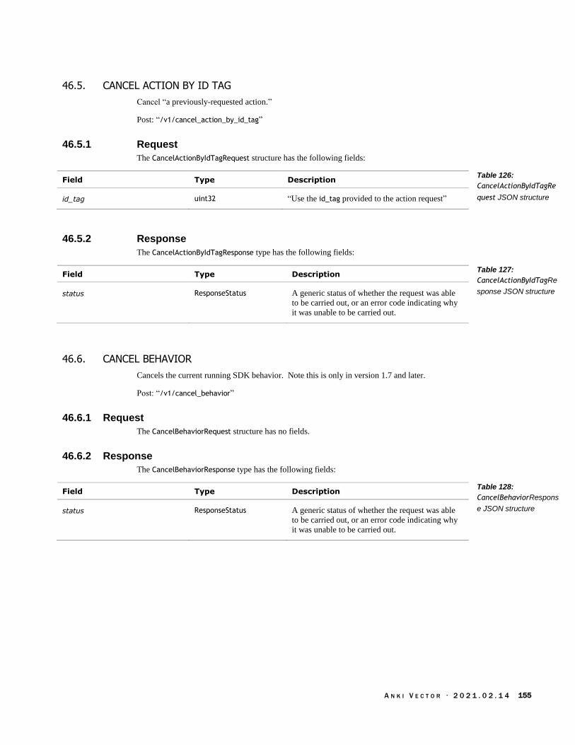
A N K I V E C T O R · 2 0 2 1 . 0 2 . 1 4 155
46.5. CANCEL ACTION BY ID TAG
Cancel “a previously-requested action.”
Post: “/v1/cancel_action_by_id_tag”
46.5.1 Request
The CancelActionByIdTagRequest structure has the following fields:
Field Type Description
id_tag uint32 “Use the id_tag provided to the action request”
46.5.2 Response
The CancelActionByIdTagResponse type has the following fields:
Field Type Description
status ResponseStatus A generic status of whether the request was able
to be carried out, or an error code indicating why
it was unable to be carried out.
46.6. CANCEL BEHAVIOR
Cancels the current running SDK behavior. Note this is only in version 1.7 and later.
Post: “/v1/cancel_behavior”
46.6.1 Request
The CancelBehaviorRequest structure has no fields.
46.6.2 Response
The CancelBehaviorResponse type has the following fields:
Field Type Description
status ResponseStatus A generic status of whether the request was able
to be carried out, or an error code indicating why
it was unable to be carried out.
Table 126:
CancelActionByIdTagRe
quest JSON structure
Table 127:
CancelActionByIdTagRe
sponse JSON structure
Table 128:
CancelBehaviorRespons
e JSON structure
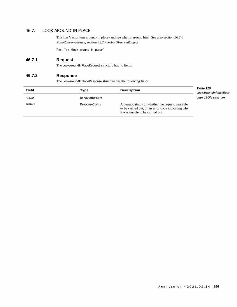
A N K I V E C T O R · 2 0 2 1 . 0 2 . 1 4 156
46.7. LOOK AROUND IN PLACE
This has Vector turn around (in place) and see what is around him. See also section 56.2.6
RobotObservedFace, section 45.2.7 RobotObservedObject
Post: “/v1/look_around_in_place”
46.7.1 Request
The LookAroundInPlaceRequest structure has no fields.
46.7.2 Response
The LookAroundInPlaceResponse structure has the following fields:
Field Type Description
result BehaviorResults
status ResponseStatus A generic status of whether the request was able
to be carried out, or an error code indicating why
it was unable to be carried out.
Table 129:
LookAroundInPlaceResp
onse JSON structure

A N K I V E C T O R · 2 0 2 1 . 0 2 . 1 4 157
47. ALEXA
47.1. ENUMERATIONS
47.1.1 AlexaAuthState
The AlexaAuthState is used represent how far in the Alexa Voice Services authorization process
Vector is. The enumeration has the following named values:
Name Value Description
ALEXA_AUTH_INVALID 0 “Invalid/error/versioning issue”
ALEXA_AUTH_UNINITIALIZED 1 “Not opted in, or opt-in attempted but failed”
ALEXA_AUTH_REQUESTING_AUTH 2 “Opted in, and attempting to authorize”
ALEXA_AUTH_WAITING_FOR_CODE 3 “Opted in, and waiting on the user to enter a code”
ALEXA_AUTH_AUTHORIZED 4 “Opted in, and authorized / in use”
47.2. EVENTS
47.2.1 AlexaAuthEvent
The AlexaAuthEvent is used to post updates to SDK application (via the Event message) when the
authorization with Alexa Voice Services change. The structure has the following fields:
Field Type Description
auth_state AlexaAuthState
extra string
Table 130:
AlexaAuthState
Enumeration
Table 131:
AlexaAuthEvent JSON
structure

A N K I V E C T O R · 2 0 2 1 . 0 2 . 1 4 158
47.3. ALEXA AUTHORIZATION STATE
This is used to find out whether Vector has been authenticated and authorized to use Alexa Voice
Services.
Post: “/v1/alexa_auth_state”
47.3.1 Request
The AlexaAuthStateRequest structure has no fields.
47.3.2 Response
The AlexaAuthStateResponse structure has the following fields:
Field Type Description
auth_state AlexaAuthState
extra string
status ResponseStatus A generic status of whether the request was able to
be carried out, or an error code indicating why it
was unable to be carried out.
47.4. ALEXA OPT IN
This is used to enable Alexa Voice Services on Vector.
Post: “/v1/alexa_opt_in”
47.4.1 Request
The AlexaOptInRequest structure has the following fields:
Field Type Description
opt_in bool True, if Vector should employ Alexa Voice
services; otherwise Vector should not.
47.4.2 Response
The AlexaOptInResponse structure has the following fields:
Field Type Description
status ResponseStatus A generic status of whether the request was able to
be carried out, or an error code indicating why it
was unable to be carried out.
Table 132:
AlexaAuthStateRespons
e JSON structure
Table 133:
AlexaOptInRequest
JSON structure
Table 134:
AlexaOptInResponse
JSON structure
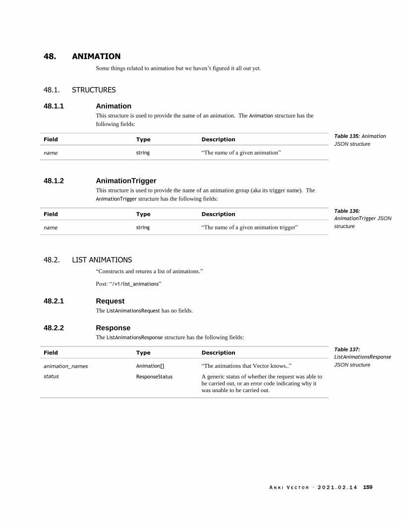
A N K I V E C T O R · 2 0 2 1 . 0 2 . 1 4 159
48. ANIMATION
Some things related to animation but we haven’t figured it all out yet.
48.1. STRUCTURES
48.1.1 Animation
This structure is used to provide the name of an animation. The Animation structure has the
following fields:
Field Type Description
name string “The name of a given animation”
48.1.2 AnimationTrigger
This structure is used to provide the name of an animation group (aka its trigger name). The
AnimationTrigger structure has the following fields:
Field Type Description
name string “The name of a given animation trigger”
48.2. LIST ANIMATIONS
“Constructs and returns a list of animations.”
Post: “/v1/list_animations”
48.2.1 Request
The ListAnimationsRequest has no fields.
48.2.2 Response
The ListAnimationsResponse structure has the following fields:
Field Type Description
animation_names Animation[] “The animations that Vector knows..”
status ResponseStatus A generic status of whether the request was able to
be carried out, or an error code indicating why it
was unable to be carried out.
Table 135: Animation
JSON structure
Table 136:
AnimationTrigger JSON
structure
Table 137:
ListAnimationsResponse
JSON structure

A N K I V E C T O R · 2 0 2 1 . 0 2 . 1 4 160
48.3. LIST ANIMATION TRIGGERS
“Constructs and returns a list of animation triggers.”
Post: “/v1/list_animation_triggers”
48.3.1 Request
The ListAnimationTriggerssRequest has no fields.
48.3.2 Response
The ListAnimationTriggersResponse structure has the following fields:
Field Type Description
animation_tigger_names AnimationTrigger[] “The animations triggers that Vector knows.”
status ResponseStatus A generic status of whether the request was able to
be carried out, or an error code indicating why it
was unable to be carried out.
48.4. PLAY ANIMATION
“Requests that Vector play an animation.”
48.4.1 Request
The PlayAnimationRequest structure has the following fields:
Field Type Units Description
animation Animation “The animation to play.”
ignore_body_track bool “Ignore any movement of Vector's body when
playing the animation.”
ignore_head_track bool “Ignore any movement of Vector's head when
playing the animation.”
ignore_lift_track bool “Ignore any movement of Vector's lift when
playing the animation.”
loops uint32 “The number of times to play the animation in a
row.”
48.4.2 Response
The PlayAnimationResponse structure has the following fields:
Field Type Description
animation Animation “The animation that the robot executed.”
result BehaviorResults “Information on whether the animation played
successfully.”
status ResponseStatus A generic status of whether the request was able to
be carried out, or an error code indicating why it
was unable to be carried out.
Table 138:
ListAnimationTriggersR
esponse JSON structure
Table 139:
PlayAnimationRequest
JSON structure
Table 140:
PlayAnimationResponse
JSON structure

A N K I V E C T O R · 2 0 2 1 . 0 2 . 1 4 161
48.5. PLAY ANIMATION TRIGGER
“Requests that Vector play an animation trigger.”
48.5.1 Request
The PlayAnimationTriggerRequest structure has the following fields:
Field Type Units Description
animation_trigger AnimationTrigger “The animation trigger to play.”
ignore_body_track bool “Ignore any movement of Vector's body when
playing the animation.”
ignore_head_track bool “Ignore any movement of Vector's head when
playing the animation.”
ignore_lift_track bool “Ignore any movement of Vector's lift when
playing the animation.”
loops uint32 “The number of times to play the animation in a
row.”
use_lift_safe bool “Automatically ignore the lift track if Vector is
currently carrying an object.”
48.5.2 Response
See the response for Play Animation.
Table 141:
PlayAnimationTriggerRe
quest JSON structure

A N K I V E C T O R · 2 0 2 1 . 0 2 . 1 4 162
49. ATTENTION TRANSFER
Note: this attention event is unlikely to be sent and the response to getting the latest attention
transfer is likely to invalid or empty, as the “AttentionTransfer” feature is disabled in all software
releases.
49.1. EVENTS
49.1.1 AttentionTransfer
This event is sent when TBD. The AttentionTransfer structure has the following fields:
Field Type Description
reason AttentionTransferReason The reason that the attention was changed.
seconds_ago float How long ago the attention was changed.
The AttentionTransferReason is used to represent why the attention was transferred. The
enumeration has the following named values:
Name Value Description
Invalid 0
NoCloudConnection 1
NoWifi 2
UnmatchedIntent 3
Table 142:
AttentionTransfer
JSON structure
Table 143:
AttentionTransferReaso
n Enumeration
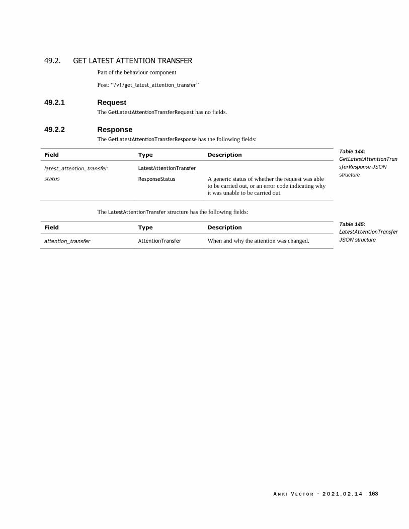
A N K I V E C T O R · 2 0 2 1 . 0 2 . 1 4 163
49.2. GET LATEST ATTENTION TRANSFER
Part of the behaviour component
Post: “/v1/get_latest_attention_transfer”
49.2.1 Request
The GetLatestAttentionTransferRequest has no fields.
49.2.2 Response
The GetLatestAttentionTransferResponse has the following fields:
Field Type Description
latest_attention_transfer LatestAttentionTransfer
status ResponseStatus A generic status of whether the request was able
to be carried out, or an error code indicating why
it was unable to be carried out.
The LatestAttentionTransfer structure has the following fields:
Field Type Description
attention_transfer AttentionTransfer When and why the attention was changed.
Table 144:
GetLatestAttentionTran
sferResponse JSON
structure
Table 145:
LatestAttentionTransfer
JSON structure

A N K I V E C T O R · 2 0 2 1 . 0 2 . 1 4 164
50. AUDIO
This section describes events and commands related to Vectors audio input and output.
50.1. ENUMERATIONS
50.1.1 AudioProcessingMode
The AudioProcessingMode is used to represent the different ways that Vector can process the
microphone audio. The enumeration has the following named values:
Name Value Description
AUDIO_UNKNOWN 0 “error value”
AUDIO_OFF 1 The audio settings from the HTTPS API will not be
used.
AUDIO_FAST_MODE 2 The spatial audio processing is disabled; the sound
is used from a single microphone. This has the
lowest processing overhead.
AUDIO_DIRECTIONAL_MODE 3 Use “beamforming support for focusing on specific
direction – [this] sounds cleanest”
AUDIO_VOICE_DETECT_MODE 4 Use “multi-microphone non-beamforming. [This
is] best for voice detection programs.”
50.1.2 MasterVolumeLevel
The MasterVolumeLevel is used to control the volume of audio played by Vector, including text to
speech. It is used in the MasterVolumeLevelRequest. The enumeration has the following named
values:
Name Value Description
VOLUME_LOW 0
VOLUME_MEDIUM_LOW 1
VOLUME_MEDIUM 2
VOLUME_MEDIUM_HIGH 3
VOLUME_HIGH 4
50.1.3 UtteranceState
The UtteranceState is used to represent the state of audio playback by Vector, including text to
speech. It is used in the SayTextResponse. The enumeration has the following named values:
Name Value Description
INVALID 0
GENERATING 1 Vector is generating the audio and other animation
for the text to speech.
Table 146:
AudioProcessingMode
Enumeration
Table 147:
MasterVolumeLevel
Enumeration
Table 148:
UtteranceState
Enumeration

A N K I V E C T O R · 2 0 2 1 . 0 2 . 1 4 165
READY 2 Vector has completed generating the audio and
animation.
PLAYING 3 Vector is playing the speech and related animation.
FINISH 4 Vector has finished playing the audio and
animation.
50.2. EVENTS
The following events are sent in the Event message. When a person speaks the wake word, the
WakeWordBegin event will be sent, followed by the WakeWordEnd event and possibly a
UserIntent event.
50.2.1 AudioSendModeChanged
Note: this event is not available; it was defined in the API protocol, but never implemented and
removed. It is reproduced here for information purposes; it may be in future releases.
This event is “sent when the robot changes the mode it's processing and sending audio” in.
See Chapter 17, section 76.2 Spatial audio processing for more information
The event structure has the following fields:
Field Type Description
mode AudioProcessingMode The requested audio processing mode.
50.2.2 UserIntent
The UserIntent event is sent by Vector when an intent is received (from the cloud), after a person
has said the wake word and spoken. The UserIntent structure has the following fields:
Field Type Description
intent_id31 uint32 The identifier for the intent. See Appendix J Table
640: Mapping of different intent names for an
enumeration.
json_data string The parameters as a JSON formatted string. This
may be empty if there is not additional information.
50.2.3 WakeWord
This event is sent when the wake word is heard, and then when the cloud response is received. The
WakeWord structure has the following fields, only one is present at any time:
Field Type Description
wake_word_begin WakeWordBegin This is sent when the wake word is heard. The
structure has no contents.
31 The use of an enumeration rather than a string is unusual here, and seems limiting.
Table 149:
AudioSendModeChanged
JSON structure
Table 150: UserIntent
JSON structure
Table 151: WakeWord
JSON structure

A N K I V E C T O R · 2 0 2 1 . 0 2 . 1 4 166
wake_word_end WakeWordEnd This is sent when the response (and potential
intent) is received from the cloud. This is sent
before the UserIntent event (if any).
The WakeWordEnd structure has the following fields:
Field Type Description
intent_heard bool True if a sentence was recognized with an
associated intent; false otherwise.
intent_json string The intent and parameters as a JSON formatted
string. This is empty if an intent was not heard
(intent_heard will be false), or if the client does not
have control. In the later case, a UserIntent event
with the intent JSON data will be sent.
Table 152:
WakeWordEnd JSON
structure
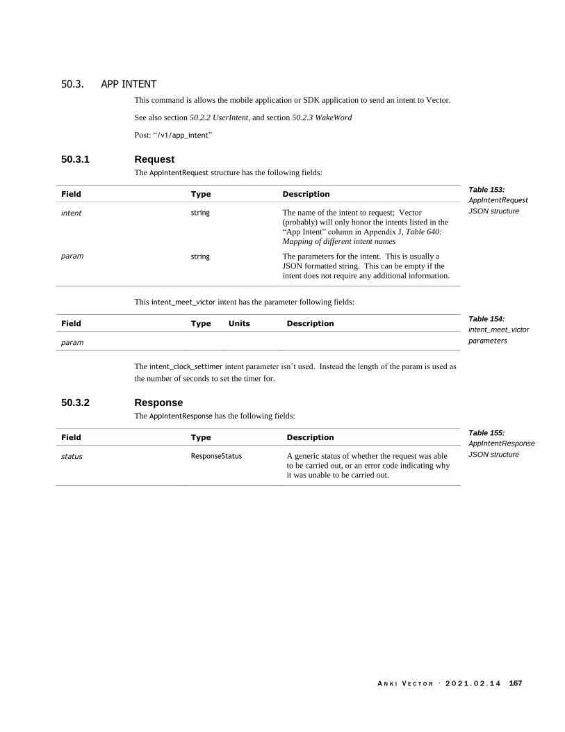
A N K I V E C T O R · 2 0 2 1 . 0 2 . 1 4 167
50.3. APP INTENT
This command is allows the mobile application or SDK application to send an intent to Vector.
See also section 50.2.2 UserIntent, and section 50.2.3 WakeWord
Post: “/v1/app_intent”
50.3.1 Request
The AppIntentRequest structure has the following fields:
Field Type Description
intent string The name of the intent to request; Vector
(probably) will only honor the intents listed in the
“App Intent” column in Appendix J, Table 640:
Mapping of different intent names
param string The parameters for the intent. This is usually a
JSON formatted string. This can be empty if the
intent does not require any additional information.
This intent_meet_victor intent has the parameter following fields:
Field Type Units Description
param
The intent_clock_settimer intent parameter isn’t used. Instead the length of the param is used as
the number of seconds to set the timer for.
50.3.2 Response
The AppIntentResponse has the following fields:
Field Type Description
status ResponseStatus A generic status of whether the request was able
to be carried out, or an error code indicating why
it was unable to be carried out.
Table 153:
AppIntentRequest
JSON structure
Table 154:
intent_meet_victor
parameters
Table 155:
AppIntentResponse
JSON structure

A N K I V E C T O R · 2 0 2 1 . 0 2 . 1 4 168
50.4. AUDIO FEED (FROM THE MICROPHONES)
Note: this command is not available; it was defined in the API protocol, but never implemented
and removed. It is reproduced here for information purposes; it may be in future releases.
This command is used to request an audio feed from Vector.
See Chapter 18, section 76.2 Spatial audio processing for more information
Post: “/v1/audio_feed”
50.4.1 Request
This AudioFeedRequest has no fields.
50.4.2 Response
The response is a stream of the following AudioFeedResponse structure. This structure has the
following fields:
Field Type Description
direction_strengths bytes “Histogram data of which directions this audio
chunk came from.”
group_id uint32 “The index of this audio feed response”
noise_floor_power uint32 The background noise level, as a “power value,
convert to db with log10(value)”
robot_time_stamp uint32 The “robot time at the transmission of this audio
sample group”
signal_power bytes The stream of sound that Vector hears, as a “mono
audio amplitude samples”. This is 1600 “16-bit
little-endian PCM audio” samples, at 11025
samples/sec.
source_confidence uint32 The “accuracy of the calculated source_direction”
source_direction uint32 0-11: The index of the direction that the voice or
key sound is coming.
12: There is no identifiable sound or the direction
cannot be determined.
Table 156:
AudioFeedResponse
JSON structure
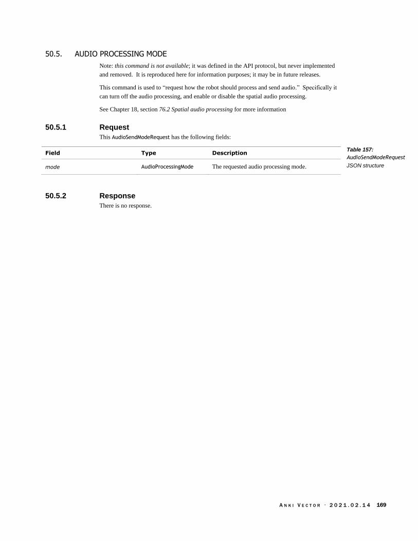
A N K I V E C T O R · 2 0 2 1 . 0 2 . 1 4 169
50.5. AUDIO PROCESSING MODE
Note: this command is not available; it was defined in the API protocol, but never implemented
and removed. It is reproduced here for information purposes; it may be in future releases.
This command is used to “request how the robot should process and send audio.” Specifically it
can turn off the audio processing, and enable or disable the spatial audio processing.
See Chapter 18, section 76.2 Spatial audio processing for more information
50.5.1 Request
This AudioSendModeRequest has the following fields:
Field Type Description
mode AudioProcessingMode The requested audio processing mode.
50.5.2 Response
There is no response.
Table 157:
AudioSendModeRequest
JSON structure

A N K I V E C T O R · 2 0 2 1 . 0 2 . 1 4 170
50.6. EXTERNAL AUDIO STREAM PLAYBACK
This command is used to stream sound files to Vector to play on his speaker. The audio is sent as
single channel (mono) 16-bit little-endian PCM (i.e. without compression or other format) at a
sample rate between 8000 samples/sec to 16205 samples/sec.
The audio is sent by:
1. Setting up the audio playback, by sending the “audio_stream_prepare” substructure with the
audio rate and value
2. Sending the audio data in chunks (up to 1024 bytes, or 512 samples) using the
“audio_stream_chunk” structure
3. repeating #2 until all of the sound data has been sent
4. Sending the “audio_stream_complete” or “audio_stream_cancel” to end the playback.
50.6.1 Request
The ExternalAudioStreamRequest is used to stream a chunk of audio to Vector. This structure has
one (and only one) of the following fields:
Field Type Description
audio_stream_cancel {} “Cancel a playing external robot audio stream”
audio_stream_chunk ExternalAudioStreamChunk
“Send chunk of audio data to stream on robot.”
audio_stream_complete {} “Send notification of last chunk of audio sent to
robot”
audio_stream_prepare ExternalAudioStreamPrepare
This is used to set up the audio channel, with the
sample rate and playback volume.
The ExternalAudioStreamPrepare structure has following fields:
Field Type Description
audio_frame_rate uint32 The sample rate for the audio. This must be in the
range of 8000 to 16025 samples/sec.
audio_volume uint32 The volume to play the audio at. 0-100
The ExternalAudioStreamChunk structure has following fields:
Field Type Description
audio_chunk_samples byte[] The audio samples, encoded as 16-bit values in
little-endian order. This must be 1024 or few
bytes
audio_chunk_size_bytes32 uint32 The number of bytes sent; the max is 1024 (i.e. a
max of 512 samples).
32 I am curious. Why does this field exist? The array intrinsically knows it size…
Table 158:
ExternalAudioStreamRe
quest JSON structure
Table 159:
ExternalAudioStreamPr
epare JSON structure
Table 160:
ExternalAudioStreamCh
unk JSON structure
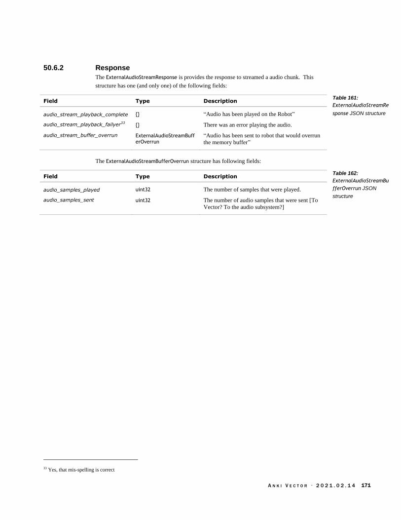
A N K I V E C T O R · 2 0 2 1 . 0 2 . 1 4 171
50.6.2 Response
The ExternalAudioStreamResponse is provides the response to streamed a audio chunk. This
structure has one (and only one) of the following fields:
Field Type Description
audio_stream_playback_complete {} “Audio has been played on the Robot”
audio_stream_playback_failyer33 {} There was an error playing the audio.
audio_stream_buffer_overrun ExternalAudioStreamBufferOverrun
“Audio has been sent to robot that would overrun
the memory buffer”
The ExternalAudioStreamBufferOverrun structure has following fields:
Field Type Description
audio_samples_played uint32 The number of samples that were played.
audio_samples_sent uint32 The number of audio samples that were sent [To
Vector? To the audio subsystem?]
33 Yes, that mis-spelling is correct
Table 161:
ExternalAudioStreamRe
sponse JSON structure
Table 162:
ExternalAudioStreamBu
fferOverrun JSON
structure

A N K I V E C T O R · 2 0 2 1 . 0 2 . 1 4 172
50.7. MASTER VOLUME
This command is used to set the volume of Vector’s audio playback and sound effects.
50.7.1 Request
The MasterVolumeResponse has the following fields:
Field Type Description
volume_level MasterVolumeLevel This is used to set the volume of Vector’s audio
playback.
50.7.2 Response
The MasterVolumeResponse has the following fields:
Field Type Description
status ResponseStatus A generic status of whether the request was able to
be carried out, or an error code indicating why it
was unable to be carried out.
Table 163:
MasterVolumeRequest
JSON structure
Table 164:
MasterVolumeResponse
JSON structure

A N K I V E C T O R · 2 0 2 1 . 0 2 . 1 4 173
50.8. SAY TEXT
This command is used to request the state of Vector speak the given text.
Post: “/v1/say_text”
50.8.1 Request
The SayTextRequest structure has the following fields:
Field Type Units Description
duration_scalar float ratio This controls the speed at which Vector speaks.
1.0 is normal rate, less than 1 increases the speed
(e.g. 0.8 causes Vector to speak in just 80% of the
usual time), and a value larger than one slows the
speed (e.g. 1.2 causes Vector to take 120% of the
usual time to speak). Allowed range is 0.5..20.0.
Default: 1.0
pitch_scalar float Negative values lower the pitch, higher values raise
the pitch. Allowed range is -1.0..1.0 Default: 0.0.
Note: this field is optional, and available only in
1.7 or later versions.
text string The text (the words) that Vector should say.
use_vector_voice bool True if the text should be spoken in “Vector's robot
voice; otherwise, he uses a generic human male
voice.”
50.8.2 Response
The SayTextResponse structure has the following fields:
Field Type Description
state UtteranceState Where in the speaking process Vector is currently.
status ResponseStatus A generic status of whether the request was able to
be carried out, or an error code indicating why it
was unable to be carried out.
TBD: are multiple responses sent as the task progresses?
Table 165:
SayTextRequest JSON
structure
Table 166:
SayTextResponse JSON
structure

A N K I V E C T O R · 2 0 2 1 . 0 2 . 1 4 174
51. BATTERY
See section 44.1.2 RobotStatus for a flag indicating that Vector is charging.
See section 59 Interactions with Objects for actions to drive onto and off of the charger.
51.1. ENUMERATIONS
The BatteryLevel enumeration is located in Chapter 8, Power Management, Table 14: BatteryLevel
codes as they apply to Vector
51.2. BATTERY STATE
This command is used to request the state of Vector’s battery and the cube battery. The state
includes its voltage, and whether Vector is charging.
Post: “/v1/battery_state”
51.2.1 Request
No parameters
51.2.2 Response
The BatteryStateResponse structure has the following fields:
Field Type Units Description
battery_level BatteryLevel The interpretation of the battery level.
battery_volts float volts The battery voltage.
cube_battery CubeBatteryLevel The status of the companion Cube’s battery.
is_on_charger_platform bool True if Vector is on his “home,” aka charger.
is_charging bool True if Vector is charging, false otherwise.
status ResponseStatus A generic status of whether the request was able to
be carried out, or an error code indicating why it
was unable to be carried out.
suggested_charger_sec float seconds Suggested amount of time to charge.
Table 167:
BatteryStateResponse
JSON structure

A N K I V E C T O R · 2 0 2 1 . 0 2 . 1 4 175
52. CONNECTION
This section describes the events and commands used to establish and maintain a connection with
Vector. This includes the ability to get the versions of the connection protocol, ant the software
used.
52.1. EVENTS
52.1.1 ConnectionResponse
The ConnectionResponse structure has the following fields:
Field Type Description
is_primary bool
status ResponseStatus A generic status of whether the request was able to
be carried out, or an error code indicating why it
was unable to be carried out.
52.1.2 Event
The Event structure is to deliver messages that some event has occurred. It is received in periodic
response to the part of the Event Stream command. All the events are carried in this one has one
(and only) of the following fields:
Field Type Description
alexa_auth_event AlexaAuthEvent
attention_transfer AttentionTransfer Not implemented?
camera_settings_update CameraSettingsUpdate This event is sent when the camera exposure
settings change.
check_update_status_response CheckUpdateStatusResponse
This event is sent when the update status has
changed.
connection_response ConnectionResponse
cube_battery CubeBattery This event is sent when the cube’s battery level
has changed.
jdocs_changed JdocsChanged This event is sent when Vector’s preference
settings have changed.
keep_alive KeepAlivePing “Used by Vector to verify the connection is still
alive.”
mirror_mode_disabled MirrorModeDisabled This event is sent when the display system has
disabled mirror mode.
object_event ObjectEvent This event is sent when an object is seen, tapped,
lost, moved, a connection was established or lost.
onboarding Onboarding
photo_taken PhotoTaken This event is sent when a photograph has been
taken.
robot_state RobotState This event is regularly sent to give the status of
the robot.
Table 168:
ConnectionResponse
JSON structure
Table 169: Event JSON
structure

A N K I V E C T O R · 2 0 2 1 . 0 2 . 1 4 176
robot_changed_observed_face_id RobotChangedObservedFaceID
This event is sent when Vector recognizes a face.
robot_erased_enrolled_face RobotErasedEnrolledFace This event is sent when a named face is removed
from the database.
robot_observed_face RobotObservedFace This event is sent when a face is seen.
robot_observed_motion RobotObservedMotion This event is sent when some visual motion is
seen.
robot_renamed_enrolled_face RobotRenamedEnrolledFace
This event is sent when the name of a face is
changed.
stimulation_info StimulationInfo This event is sent when stimulation from internal
or external events is received.
time_stamped_status TimeStampedStatus
unexpected_movement Unexpected Movement This event is sent when Vector’s body moves in a
way that was not expected.
user_intent UserIntent This event is sent when a user intent has been
received and is being acted upon.
vision_modes_auto_disabled VisionModesAutoDisabled This event is sent when the vision system has
disabled further updates.
wake_word WakeWord This event is sent when the wake word has been
heard.
52.1.3 KeepAlivePing
This is “a null message used by streams to verify that the client is still connected.” This message
has no fields.
52.1.4 TimeStampedStatus
The TimeStampedStatus structure has the following fields:
Field Type Description
status Status
timestamp_utc uint32 The time that the status occurred on. The format is
unix time: seconds since 1970, in UTC.
The Status structure has one (and only one) of the following fields:
Field Type Description
face_enrollment_completed FaceEnrollmentComplete
feature_status FeatureStatus This event is sent when the high-level AI changes
Vector’s behavior.
meet_victor_face_scan_complete Meet Victor Face Scan Complete
meet_victor_face_scan_started Meet Victor Face Scan Started
Table 170:
TimeStampedStatus
JSON structure
Table 171: Status JSON
structure

A N K I V E C T O R · 2 0 2 1 . 0 2 . 1 4 177
52.2. EVENT STREAM
This command is used to request a stream of events from Vector.
Post: “"/v1/event_stream”
Get: “"/v1/event_stream”
52.2.1 Request
The EventRequest has the following fields:
Field Type Description
black_list FilterList The list of events to not include. ?
connection_id string
white_list FilterList The list of events to include.
The FilterList structure has the following fields:
Field Type Description
list string[] A list of events
52.2.2 Response
The response is a stream of EventResponse structures. These have the following fields:
Field Type Description
event Event The event that occurred. This structure is described
above in the subsection Eents
status ResponseStatus A generic status of whether the request was able to
be carried out, or an error code indicating why it
was unable to be carried out.
Table 172:
EventRequest JSON
structure
Table 173: FilterList
JSON structure
Table 174:
EventResponse JSON
structure

A N K I V E C T O R · 2 0 2 1 . 0 2 . 1 4 178
52.3. PROTOCOL VERSION
“Checks the supported protocol version by passing in the client version and minimum host version
and receiving a response to see whether the versions are supported.”
Post: “/v1/protocol_version”
“The valid versions of the protocol. Protocol versions are updated when messages change
significantly: new ones are added and removed, fields deprecated, etc. The goal is to support as
many old versions as possible, only bumping the minimum when there is no way to handle a prior
version.”
52.3.1 Request
The ProtocolVersionRequest has the following fields:
Field Type Description
client_version int64 The version of the protocol that the client is using.
min_host_version int64 The minimum version level of the protocol that
robot should support.
52.3.2 Response
The ProtocolVersionResponse has the following fields:
Field Type Description
host_version int64 The version of the protocol that the robot supports.
result Result Whether or not the protocol version supported by
the robot is compatible with the client. See below.
The Result is used to indicate whether the client version is supported. The enumeration has the
following named values:
Name Value Description
SUPPORTED 1 The protocol supports the client version and the
minimum host (robot) version of the protocol.
UNSUPPORTED 0 The protocol is unable to support the client; either
the client version is not supported, or the host is
unable to support a compatible version of the
protocol.
Table 175:
ProtocolVersionRequest
JSON structure
Table 176:
ProtocolVersionRespon
se JSON structure
Table 177: Result
Enumeration

A N K I V E C T O R · 2 0 2 1 . 0 2 . 1 4 179
52.4. SDK INITIALIZATION
“SDK-only message to pass version info for device OS, Python version, etc.”
Post: “/v1/sdk_initialization”
52.4.1 Request
The SDKInitializationRequest has the following fields:
Field Type Description
cpu_version string The CPU model that the client (SDK) is using;
informational only.
os_version string The version of operating system that the client
(SDK) is using; informational only.
python_implementation string
python_version string The version of python that the client (SDK) is
using. Informational only.
sdk_module_version string The version of the SDK software that the client is
using.
52.4.2 Response
The SDKInitializationResponse type has the following fields:
Field Type Description
status ResponseStatus A generic status of whether the request was able to
be carried out, or an error code indicating why it
was unable to be carried out.
Table 178:
SDKInitializationReques
t JSON structure
Table 179:
SDKInitializationRespon
se JSON structure

A N K I V E C T O R · 2 0 2 1 . 0 2 . 1 4 180
52.5. USER AUTHENTICATION
This command is used to authenticate
Post: “/v1/user_authentication”
52.5.1 Request
The UserAuthenticationRequest has the following fields:
Field Type Description
client_name bytes
user_session_id bytes
52.5.2 Response
The UserAuthenticationResponse has the following fields:
Field Type Description
client_token_guid bytes The token bytes to be included in subsequent
HTTPS postings. This token should be saved for
future use.
code Code The result of the authentication request
status ResponseStatus A generic status of whether the request was able to
be carried out, or an error code indicating why it
was unable to be carried out.
The Code enumeration is:
Name Value Description
UNAUTHORIZED 0
AUTHORIZED 1
Table 180:
UserAuthenticationRequ
est JSON structure
Table 181:
UserAuthenticationResp
onse JSON structure
Table 182: Code
Enumeration

A N K I V E C T O R · 2 0 2 1 . 0 2 . 1 4 181
52.6. VERSION STATE
Retrieves Vector’s version information.
Post: “/v1/version_state”
52.6.1 Request
The VersionStateRequest has no fields.
52.6.2 Response
The VersionStateResponse type has the following fields:
Field Type Description
engine_build_id string The robot’s software build identifier.
status ResponseStatus A generic status of whether the request was able to
be carried out, or an error code indicating why it
was unable to be carried out.
os_version string The identifier of the robot’s software version.
Table 183:
VersionStateResponse
JSON structure

A N K I V E C T O R · 2 0 2 1 . 0 2 . 1 4 182
53. CUBE
This section describes the structures and commands to interact with the cube.
Comment: Many of the commands are specific to interacting with a cube, but appear to have been
intended to be generalized to work with a wider range of objects.
See also section 45.4 Define Custom Object for a description how to create custom box and cube
objects.
The cube’s unique identifier is called “factory_id” in these messages.
53.1. ENUMERATIONS
53.1.1 AlignmentType
The AlignmentType is used to indicate how Vector should align with the object. The enumeration
has the following named values:
Name Value Description
ALIGNMENT_TYPE_UNKNOWN 0
ALIGNMENT_TYPE_LIFT_FINGER 1 “Align the tips of the lift fingers with the target
object”
ALIGNMENT_TYPE_LIFT_PLATE 2 “Align the flat part of the lift with the object (useful
for getting the fingers in the cube's grooves)”
ALIGNMENT_TYPE_BODY 3 “Align the front of Vector's body (useful for when
the lift is up)”
ALIGNMENT_TYPE_CUSTOM 4 “For use with distanceFromMarker parameter”
53.1.2 CubeBatteryLevel
The CubeBatteryLevel enumeration is used to categorize the condition of the Cube battery:
Name Value Description
BATTERY_LEVEL_LOW 0 The Cube battery is 1.1V or less.
BATTERY_LEVEL_NORMAL 1 The Cube battery is at normal operating levels, i.e.
>1.1v
34 The levels are from robot.py
Table 184:
AlignmentType
Enumeration
Table 185:
CubeBatteryLevel
codes34
as they apply
to Vector

A N K I V E C T O R · 2 0 2 1 . 0 2 . 1 4 183
53.2. EVENTS
53.2.1 CubeBattery
The CubeBattery structure has the following fields:
Field Type Units Description
battery_volts float volts The battery voltage.
factory_id string The text string reported by the cube via Bluetooth
LE.
level CubeBatteryLevel The interpretation of the battery level.
time_since_last_reading_sec float seconds The number of seconds that have elapsed since the
last Bluetooth LE message from the cube with a
battery level measure.
53.2.2 CubeConnectionLost
“Indicates that the connection subscribed through ConnectCube has been lost.”
See also ObjectConnectionState
The ConnectCubeRequest has no fields.
53.2.3 ObjectTapped
The ObjectTapped event is sent (see ObjectEvent) when an object has received a finger-tap. This
event is only sent by the cube. Note: this event can have false triggers; it may sent when Vector is
picking up, carrying, or putting down the Cube.
The structure has the following fields:
Field Type Units Description
object_id uint32 The identifier of the object tapped.
timestamp uint32 The time that the event occurred on. The format
is milliseconds since Vector’s epoch.
Table 186: CubeBattery
JSON structure
Table 187:
ObjectTapped JSON
structure

A N K I V E C T O R · 2 0 2 1 . 0 2 . 1 4 184
53.3. CONNECT CUBE
“Attempt to connect to a cube. If a cube is currently connected, this will do nothing.”
Post: “/v1/connect_cube”
53.3.1 Request
The ConnectCubeRequest has no fields.
53.3.2 Response
The ConnectCubeResponse type has the following fields:
Field Type Description
factory_id string The identifier for the cube. This is built into the
cube.
object_id uint32 The identifier of the cube that we connected with.
This is Vector’s internal identifier, and only the
preferred cube is assigned one.
status ResponseStatus A generic status of whether the request was able to
be carried out, or an error code indicating why it
was unable to be carried out.
success bool True if Vector was able to successfully connect, via
Bluetooth LE, with the cube.
53.4. CUBES AVAILABLE
Have Vector scan for cubes via Bluetooth LE and report the ones heard.
Post: “/v1/cubes_available”
53.4.1 Request
The CubesAvailableRequest has no fields.
53.4.2 Response
The CubesAvailableResponse is sent to indicate whether the action successfully completed or not.
This structure has the following fields:
Field Type Description
factory_ids string[] A list of the cubes that were seen via Bluetooth LE.
The cubes internal identifier (it’s factor id) is sent.
status ResponseStatus A generic status of whether the request was able to
be carried out, or an error code indicating why it
was unable to be carried out.
Table 188:
ConnectCubeResponse
JSON structure
Table 189:
CubesAvailableRespons
e JSON structure
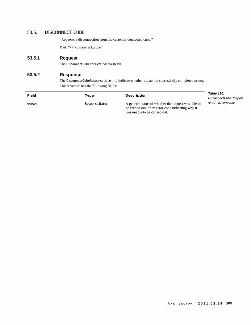
A N K I V E C T O R · 2 0 2 1 . 0 2 . 1 4 185
53.5. DISCONNECT CUBE
“Requests a disconnection from the currently connected cube.”
Post: “/v1/disconnect_cube”
53.5.1 Request
The DisconnectCubeRequest has no fields.
53.5.2 Response
The DisconnectCubeResponse is sent to indicate whether the action successfully completed or not.
This structure has the following fields:
Field Type Description
status ResponseStatus A generic status of whether the request was able to
be carried out, or an error code indicating why it
was unable to be carried out.
Table 190:
DisconnectCubeRespon
se JSON structure

A N K I V E C T O R · 2 0 2 1 . 0 2 . 1 4 186
53.6. DOCK WITH CUBE
“Tells Vector to dock with a light cube with [an optional] given approach angle and distance.”
“While docking with the cube, Vector will use path planning.”
This action requires the use of the wheels (tracks). “Actions that use the wheels cannot be
performed at the same time; otherwise you may see a TRACKS_LOCKED error.”
Post: “/v1/dock_with_cube”
53.6.1 Request
The DockWithCubeRequest structure has the following fields:
Field Type Units Description
alignment_type AlignmentType “Which part of the robot to align with the object.”
approach_angle_rad float radians “The angle to approach the cube from. For
example, 180 degrees will cause Vector to drive
past the cube and approach it from behind.”
distance_from_marker_mm float mm “The distance from the object to stop. This is the
distance between the origins.” 0mm to dock.
id_tag int32 This is an action tag that can be assigned to this
request and used later to cancel the action.
Optional.
motion_prof PathMotionProfile Modifies how Vector should approach the cube.
Optional.
num_retries int32 Maximum of times to attempt to reach the object.
A retry is attempted if Vector is unable to reach the
target object.
object_id int32 The identifier of the object to dock with.
use_approach_angle bool If true, Vector will approach the cube from the
given approach angle; otherwise Vector will
approach from the most convenient angle.
use_pre_dock_pose bool If true, “try to immediately [dock with the] object
or first position the robot next to the object.”
Recommended to set this to the same as
use_approach_angle.
53.6.2 Response
The DockWithCubeResponse is sent to indicate whether the action successfully completed or not.
This structure has the following fields:
Field Type Description
result ActionResult An error code indicating the success of the action,
the detailed reason why it failed, or that the action
is still being carried out.
status ResponseStatus A generic status of whether the request was able to
be carried out, or an error code indicating why it
was unable to be carried out.
Table 191:
DockWithCubeRequest
JSON structure
Table 192:
DockWithCubeResponse
JSON structure
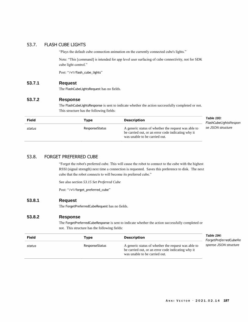
A N K I V E C T O R · 2 0 2 1 . 0 2 . 1 4 187
53.7. FLASH CUBE LIGHTS
“Plays the default cube connection animation on the currently connected cube's lights.”
Note: “This [command] is intended for app level user surfacing of cube connectivity, not for SDK
cube light control.”
Post: “/v1/flash_cube_lights”
53.7.1 Request
The FlashCubeLightsRequest has no fields.
53.7.2 Response
The FlashCubeLightsResponse is sent to indicate whether the action successfully completed or not.
This structure has the following fields:
Field Type Description
status ResponseStatus A generic status of whether the request was able to
be carried out, or an error code indicating why it
was unable to be carried out.
53.8. FORGET PREFERRED CUBE
“Forget the robot's preferred cube. This will cause the robot to connect to the cube with the highest
RSSI (signal strength) next time a connection is requested. Saves this preference to disk. The next
cube that the robot connects to will become its preferred cube.”
See also section 53.15 Set Preferred Cube
Post: “/v1/forget_preferred_cube”
53.8.1 Request
The ForgetPreferredCubeRequest has no fields.
53.8.2 Response
The ForgetPreferredCubeResponse is sent to indicate whether the action successfully completed or
not. This structure has the following fields:
Field Type Description
status ResponseStatus A generic status of whether the request was able to
be carried out, or an error code indicating why it
was unable to be carried out.
Table 193:
FlashCubeLightsRespon
se JSON structure
Table 194:
ForgetPreferredCubeRe
sponse JSON structure

A N K I V E C T O R · 2 0 2 1 . 0 2 . 1 4 188
53.9. PICKUP OBJECT
“Instruct the robot to pick up the supplied object.” “While picking up the cube, Vector will use
path planning.”
“Note that actions that use the wheels cannot be performed at the same time, otherwise you may
see a TRACKS_LOCKED error.”
53.9.1 Request
The PickupObjectRequest structure has the following fields:
Field Type Units Description
approach_angle_rad float radians “The angle to approach the cube from. For
example, 180 degrees will cause Vector to drive
past the cube and approach it from behind.”
id_tag int32 This is an action tag that can be assigned to this
request and used later to cancel the action.
Optional.
motion_prof PathMotionProfile Optional.
num_retries int32 Maximum of times to attempt to reach the object.
A retry is attempted if Vector is unable to reach the
target object.
object_id int32 The identifier of the object to pick up. `Negative
value means currently selected object’
use_approach_angle bool If true, Vector will approach the cube from the
given approach angle; otherwise Vector will
approach from the most convenient angle.
use_pre_dock_pose bool “Whether or not to try to immediately pick up an
object or first position the robot next to the object.”
53.9.2 Response
The PickupObjectResponse is sent to indicate whether the action successfully completed or not.
This structure has the following fields:
Field Type Description
result ActionResult An error code indicating the success of the action,
the detailed reason why it failed, or that the action
is still being carried out.
status ResponseStatus A generic status of whether the request was able to
be carried out, or an error code indicating why it
was unable to be carried out.
Table 195:
PickupObjectRequest
JSON structure
Table 196:
PickupObjectResponse
JSON structure
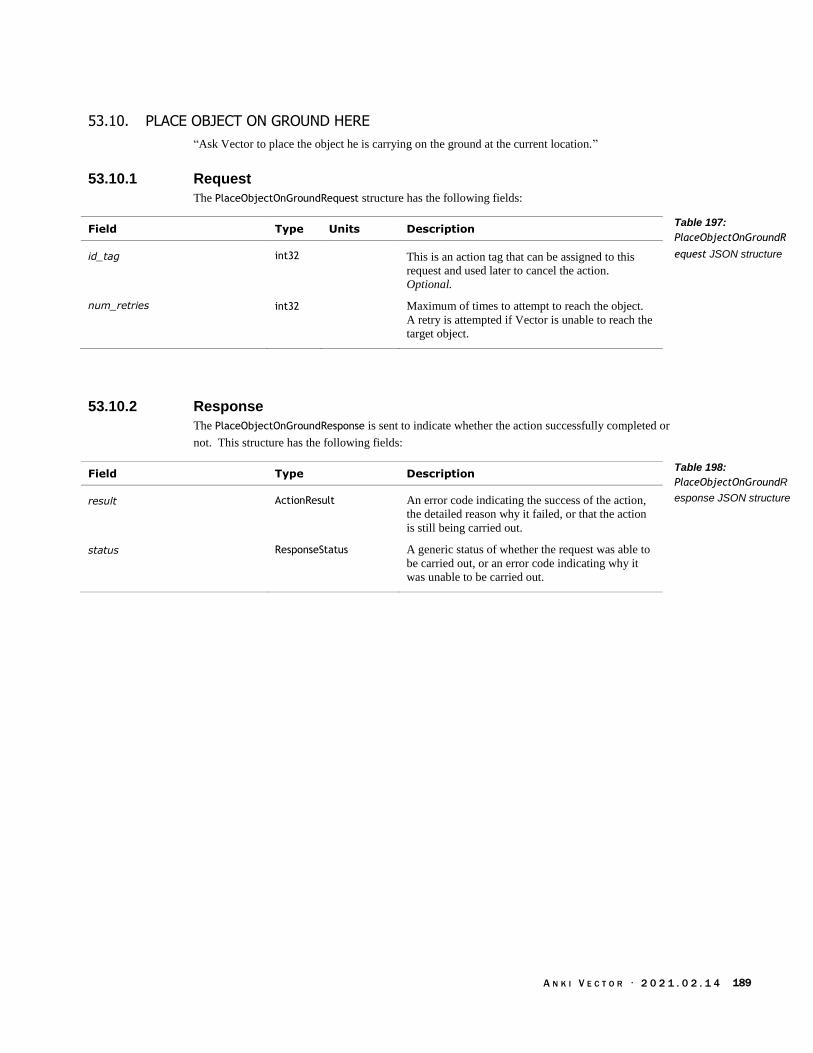
A N K I V E C T O R · 2 0 2 1 . 0 2 . 1 4 189
53.10. PLACE OBJECT ON GROUND HERE
“Ask Vector to place the object he is carrying on the ground at the current location.”
53.10.1 Request
The PlaceObjectOnGroundRequest structure has the following fields:
Field Type Units Description
id_tag int32 This is an action tag that can be assigned to this
request and used later to cancel the action.
Optional.
num_retries int32 Maximum of times to attempt to reach the object.
A retry is attempted if Vector is unable to reach the
target object.
53.10.2 Response
The PlaceObjectOnGroundResponse is sent to indicate whether the action successfully completed or
not. This structure has the following fields:
Field Type Description
result ActionResult An error code indicating the success of the action,
the detailed reason why it failed, or that the action
is still being carried out.
status ResponseStatus A generic status of whether the request was able to
be carried out, or an error code indicating why it
was unable to be carried out.
Table 197:
PlaceObjectOnGroundR
equest JSON structure
Table 198:
PlaceObjectOnGroundR
esponse JSON structure
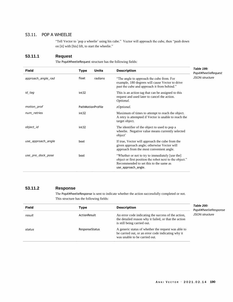
A N K I V E C T O R · 2 0 2 1 . 0 2 . 1 4 190
53.11. POP A WHEELIE
“Tell Vector to `pop a wheelie’ using his cube.” Vector will approach the cube, then “push down
on [it] with [his] lift, to start the wheelie.”
53.11.1 Request
The PopAWheelieRequest structure has the following fields:
Field Type Units Description
approach_angle_rad float radians “The angle to approach the cube from. For
example, 180 degrees will cause Vector to drive
past the cube and approach it from behind.”
id_tag int32 This is an action tag that can be assigned to this
request and used later to cancel the action.
Optional.
motion_prof PathMotionProfile zOptional.
num_retries int32 Maximum of times to attempt to reach the object.
A retry is attempted if Vector is unable to reach the
target object.
object_id int32 The identifier of the object to used to pop a
wheelie. Negative value means currently selected
object’
use_approach_angle bool If true, Vector will approach the cube from the
given approach angle; otherwise Vector will
approach from the most convenient angle.
use_pre_dock_pose bool “Whether or not to try to immediately [use the]
object or first position the robot next to the object.”
Recommended to set this to the same as
use_approach_angle.
53.11.2 Response
The PopAWheelieResponse is sent to indicate whether the action successfully completed or not.
This structure has the following fields:
Field Type Description
result ActionResult An error code indicating the success of the action,
the detailed reason why it failed, or that the action
is still being carried out.
status ResponseStatus A generic status of whether the request was able to
be carried out, or an error code indicating why it
was unable to be carried out.
Table 199:
PopAWheelieRequest
JSON structure
Table 200:
PopAWheelieResponse
JSON structure
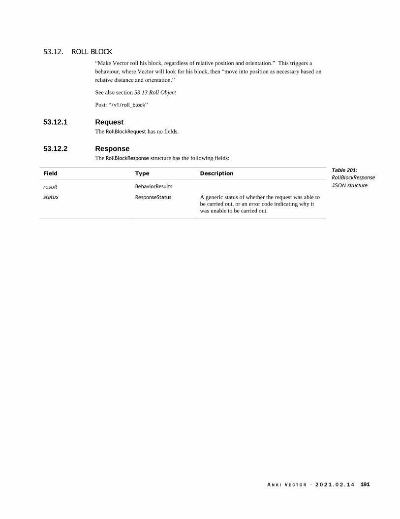
A N K I V E C T O R · 2 0 2 1 . 0 2 . 1 4 191
53.12. ROLL BLOCK
“Make Vector roll his block, regardless of relative position and orientation.” This triggers a
behaviour, where Vector will look for his block, then “move into position as necessary based on
relative distance and orientation.”
See also section 53.13 Roll Object
Post: “/v1/roll_block”
53.12.1 Request
The RollBlockRequest has no fields.
53.12.2 Response
The RollBlockResponse structure has the following fields:
Field Type Description
result BehaviorResults
status ResponseStatus A generic status of whether the request was able to
be carried out, or an error code indicating why it
was unable to be carried out.
Table 201:
RollBlockResponse
JSON structure
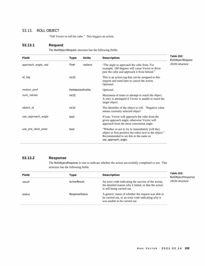
A N K I V E C T O R · 2 0 2 1 . 0 2 . 1 4 192
53.13. ROLL OBJECT
“Tell Vector to roll his cube.” This triggers an action.
53.13.1 Request
The RollObjectRequest structure has the following fields:
Field Type Units Description
approach_angle_rad float radians “The angle to approach the cube from. For
example, 180 degrees will cause Vector to drive
past the cube and approach it from behind.”
id_tag int32 This is an action tag that can be assigned to this
request and used later to cancel the action.
Optional.
motion_prof PathMotionProfile Optional.
num_retries int32 Maximum of times to attempt to reach the object.
A retry is attempted if Vector is unable to reach the
target object.
object_id int32 The identifier of the object to roll. `Negative value
means currently selected object’
use_approach_angle bool If true, Vector will approach the cube from the
given approach angle; otherwise Vector will
approach from the most convenient angle.
use_pre_dock_pose bool “Whether or not to try to immediately [roll the]
object or first position the robot next to the object.”
Recommended to set this to the same as
use_approach_angle.
53.13.2 Response
The RollObjectResponse is sent to indicate whether the action successfully completed or not. This
structure has the following fields:
Field Type Description
result ActionResult An error code indicating the success of the action,
the detailed reason why it failed, or that the action
is still being carried out.
status ResponseStatus A generic status of whether the request was able to
be carried out, or an error code indicating why it
was unable to be carried out.
Table 202:
RollObjectRequest
JSON structure
Table 203:
RollObjectResponse
JSON structure
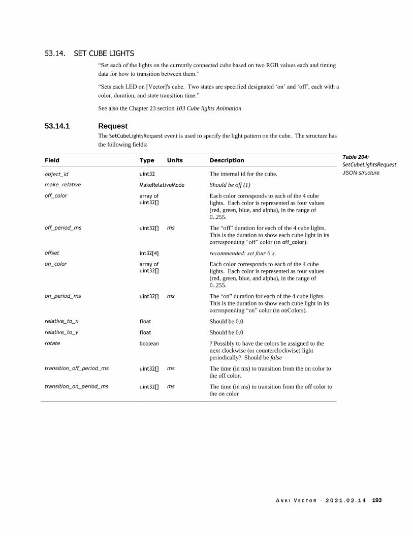
A N K I V E C T O R · 2 0 2 1 . 0 2 . 1 4 193
53.14. SET CUBE LIGHTS
“Set each of the lights on the currently connected cube based on two RGB values each and timing
data for how to transition between them.”
“Sets each LED on [Vector]'s cube. Two states are specified designated ‘on’ and ‘off’, each with a
color, duration, and state transition time.”
See also the Chapter 23 section 103 Cube lights Animation
53.14.1 Request
The SetCubeLightsRequest event is used to specify the light pattern on the cube. The structure has
the following fields:
Field Type Units Description
object_id uint32 The internal id for the cube.
make_relative MakeRelativeMode Should be off (1)
off_color array of uint32[]
Each color corresponds to each of the 4 cube
lights. Each color is represented as four values
(red, green, blue, and alpha), in the range of
0..255.
off_period_ms uint32[] ms The “off” duration for each of the 4 cube lights.
This is the duration to show each cube light in its
corresponding “off” color (in off_color).
offset int32[4] recommended: set four 0’s.
on_color array of uint32[]
Each color corresponds to each of the 4 cube
lights. Each color is represented as four values
(red, green, blue, and alpha), in the range of
0..255.
on_period_ms uint32[] ms The “on” duration for each of the 4 cube lights.
This is the duration to show each cube light in its
corresponding “on” color (in onColors).
relative_to_x float Should be 0.0
relative_to_y float Should be 0.0
rotate boolean ? Possibly to have the colors be assigned to the
next clockwise (or counterclockwise) light
periodically? Should be false
transition_off_period_ms uint32[] ms The time (in ms) to transition from the on color to
the off color.
transition_on_period_ms uint32[] ms The time (in ms) to transition from the off color to
the on color
Table 204:
SetCubeLightsRequest
JSON structure

A N K I V E C T O R · 2 0 2 1 . 0 2 . 1 4 194
The MakeRelativeMode is used to indicate how Vector should align with the object. The
enumeration has the following named values:
Name Value Description
UNKNOWN 0
OFF 1
BY_CORNER 2
BY_SIDE 3
53.14.2 Response
The SetCubeLightsResponse is sent to indicate whether the action successfully completed or not.
This structure has the following fields:
Field Type Description
status ResponseStatus A generic status of whether the request was able to
be carried out, or an error code indicating why it
was unable to be carried out.
53.15. SET PREFERRED CUBE
“Set the robot's preferred cube and save it to disk. The robot will always attempt to connect to this
cube if it is available. This is only used in simulation for now.”
Post: “/v1/set_preferred_cube”
53.15.1 Request
The SetPreferredCubeRequest structure has the following fields:
Field Type Units Description
factory_id string The identifier of the cube to use. This is built into
the cube.
53.15.2 Response
The SetPreferredCubeResponse is sent to indicate whether the action successfully completed or not.
This structure has the following fields:
Field Type Description
status ResponseStatus A generic status of whether the request was able to
be carried out, or an error code indicating why it
was unable to be carried out.
Table 205:
MakeRelativeMode
Enumeration
Table 206:
SetCubeLightsResponse
JSON structure
Table 207:
SetPreferredCubeReque
st JSON structure
Table 208:
SetPreferredCubeRespo
nse JSON structure
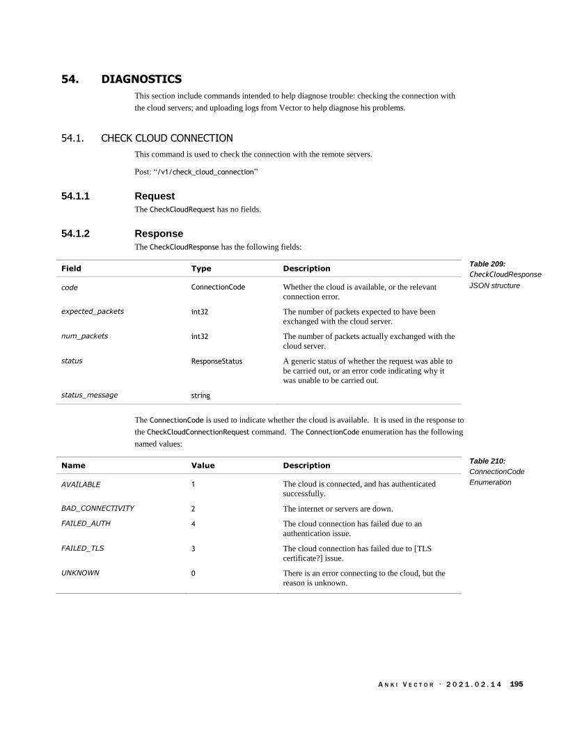
A N K I V E C T O R · 2 0 2 1 . 0 2 . 1 4 195
54. DIAGNOSTICS
This section include commands intended to help diagnose trouble: checking the connection with
the cloud servers; and uploading logs from Vector to help diagnose his problems.
54.1. CHECK CLOUD CONNECTION
This command is used to check the connection with the remote servers.
Post: “/v1/check_cloud_connection”
54.1.1 Request
The CheckCloudRequest has no fields.
54.1.2 Response
The CheckCloudResponse has the following fields:
Field Type Description
code ConnectionCode Whether the cloud is available, or the relevant
connection error.
expected_packets int32 The number of packets expected to have been
exchanged with the cloud server.
num_packets int32 The number of packets actually exchanged with the
cloud server.
status ResponseStatus A generic status of whether the request was able to
be carried out, or an error code indicating why it
was unable to be carried out.
status_message string
The ConnectionCode is used to indicate whether the cloud is available. It is used in the response to
the CheckCloudConnectionRequest command. The ConnectionCode enumeration has the following
named values:
Name Value Description
AVAILABLE 1 The cloud is connected, and has authenticated
successfully.
BAD_CONNECTIVITY 2 The internet or servers are down.
FAILED_AUTH 4 The cloud connection has failed due to an
authentication issue.
FAILED_TLS 3 The cloud connection has failed due to [TLS
certificate?] issue.
UNKNOWN 0 There is an error connecting to the cloud, but the
reason is unknown.
Table 209:
CheckCloudResponse
JSON structure
Table 210:
ConnectionCode
Enumeration
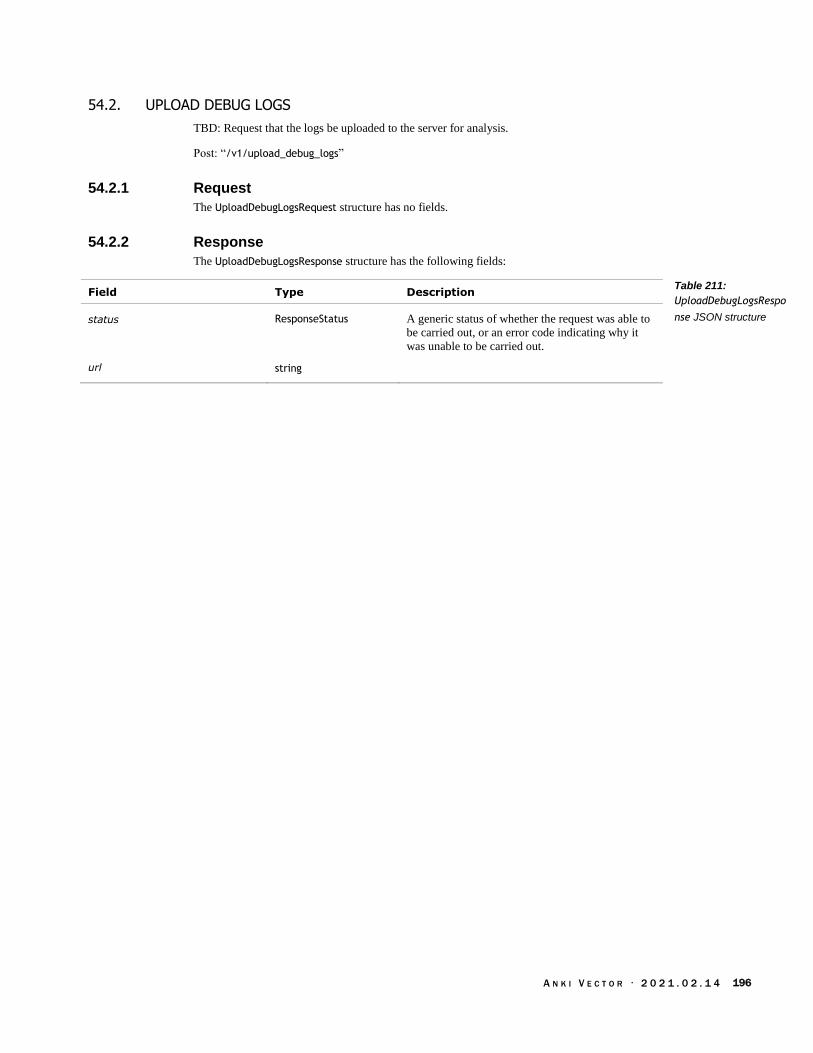
A N K I V E C T O R · 2 0 2 1 . 0 2 . 1 4 196
54.2. UPLOAD DEBUG LOGS
TBD: Request that the logs be uploaded to the server for analysis.
Post: “/v1/upload_debug_logs”
54.2.1 Request
The UploadDebugLogsRequest structure has no fields.
54.2.2 Response
The UploadDebugLogsResponse structure has the following fields:
Field Type Description
status ResponseStatus A generic status of whether the request was able to
be carried out, or an error code indicating why it
was unable to be carried out.
url string
Table 211:
UploadDebugLogsRespo
nse JSON structure

A N K I V E C T O R · 2 0 2 1 . 0 2 . 1 4 197
55. DISPLAY
This section describes commands that are used to display imagery on Vector’s LCD.
55.1. EVENTS
55.1.1 MirrorModeDisabled
The MirrorModeDisabled event is sent (see Event) “if MirrorMode (camera feed displayed on face) is
currently enabled but is automatically being disabled.”
The MirrorModeDisabled structure has no fields.
55.2. DISPLAY IMAGE RGB
“Sets screen (Vector's face) to” display the passed image.
Post: “/v1/display_face_image_rgb”
55.2.1 Request
The DisplayFaceImageRGBRequest structure has the following fields:
Field Type Units Description
duration_ms uint32 ms “How long to display the image on the face.”
face_data bytes The raw data for the image to display. The LCD is
184x96, with RGB565 pixels (16 bits/pixel).
interrupt_running bool “If this image should overwrite any current images
on the face.”
55.2.2 Response
The DisplayFaceImageRGBResponse structure has the following fields:
Field Type Description
status ResponseStatus A generic status of whether the request was able to
be carried out, or an error code indicating why it
was unable to be carried out.
Table 212:
DisplayFaceImageRGBRe
quest JSON structure
Table 213:
DisplayFaceImageRGBRe
sponse JSON structure

A N K I V E C T O R · 2 0 2 1 . 0 2 . 1 4 198
55.3. ENABLE MIRROR MODE
“When enabled, camera feed will appear on the robot's face, along with any detections” (if
enabled).
Post: “/v1/enable_mirror_mode”
55.3.1 Request
The EnableMirrorModeRequest message has the following fields:
Field Type Description
enable bool If true, enables displaying the camera feed (and
detections) on the LCD.
55.3.2 Response
The EnableMirrorModeResponse structure has the following fields:
Field Type Description
status ResponseStatus A generic status of whether the request was able to
be carried out, or an error code indicating why it
was unable to be carried out.
55.4. SET EYE COLOR
This is used to set Vector’s current eye color. See also section 66 Settings and Preferences
Post: “/v1/set_eye_color”
55.4.1 Request
The SetEyeColorRequest has the following fields:
Field Type Description
hue float The hue to set Vector’s eyes to.
saturation float The saturation of the color to set Vector’s eyes to.
55.4.2 Response
The SetEyeColorResponse structure has the following fields:
Field Type Description
status ResponseStatus A generic status of whether the request was able to
be carried out, or an error code indicating why it
was unable to be carried out.
Table 214:
EnableMirrorModeRequ
est JSON structure
Table 215:
EnableMirrorModeRespo
nse JSON structure
Table 216:
SetEyeColorRequest
JSON structure
Table 217:
SetEyeColorResponse
JSON structure

A N K I V E C T O R · 2 0 2 1 . 0 2 . 1 4 199
56. FACES
This section describes the commands and queries related to Vector’s detection of faces, and
managing what he knows about them. For a description of the facial detection and recognition
process, see Chapter 19 section 82 Face and Facial features recognition.
Note: an int32 identifier is used to distinguish between faces that are seen. Each face will have a
separate identifier. A positive identifier is used for a face that is known (recognized). This value
will be the same when the face disappears and reappears later; the value likely persists across
reboots. A negative identifier is used for face that is not recognized; as unknown faces appear and
disappear they may be assigned different subsequent negative numbers. If a face becomes
recognized, a RobotChangedObservedFaceID event will be sent, along with a change in identifier
used.
see also section 64 On boarding
56.1. ENUMERATIONS
56.1.1 FaceEnrollmentResult
The FaceEnrollmentResult is used to represent the success of associating a face with a name, or an
reason code if there was an error. The enumeration has the following named values:
Name Value Description
SUCCESS 0 A face was seen, its facial signature and associated
name were successfully saved.
SAW_WRONG_FACE 1
SAW_MULTIPLE_FACES 2 Too many faces were seen, and Vector did not
know which one to associate with the name.
TIMED_OUT 3
SAVED_FAILED 4 There was an error saving the facial signature and
associated name to non-volatile storage.
INCOMPLETE 5
CANCELLED 6 See Cancel Face Enrollment.
NAME_IN_USE 7
NAMED_STORAGE_FULL 8 There was no more room in the non-volatile storage
to hold another facial signature and associated
name.
UNKOWN_FAILURE 9
56.1.2 FacialExpression
The FacialExpression is used to estimate the emotion expressed by each face that vector sees. The
enumeration has the following named values:
Name Value Description
EXPRESSION_UNKNOWN 0 The facial expression could not be estimated. Note:
this could be because the facial expression
Table 218:
FacialExpression
Enumeration
Table 219:
FacialExpression
Enumeration
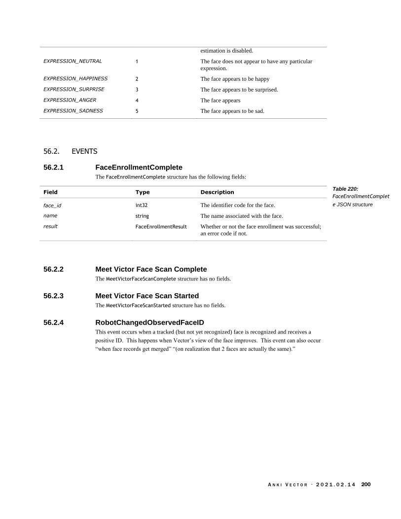
A N K I V E C T O R · 2 0 2 1 . 0 2 . 1 4 200
estimation is disabled.
EXPRESSION_NEUTRAL 1 The face does not appear to have any particular
expression.
EXPRESSION_HAPPINESS 2 The face appears to be happy
EXPRESSION_SURPRISE 3 The face appears to be surprised.
EXPRESSION_ANGER 4 The face appears
EXPRESSION_SADNESS 5 The face appears to be sad.
56.2. EVENTS
56.2.1 FaceEnrollmentComplete
The FaceEnrollmentComplete structure has the following fields:
Field Type Description
face_id int32 The identifier code for the face.
name string The name associated with the face.
result FaceEnrollmentResult Whether or not the face enrollment was successful;
an error code if not.
56.2.2 Meet Victor Face Scan Complete
The MeetVictorFaceScanComplete structure has no fields.
56.2.3 Meet Victor Face Scan Started
The MeetVictorFaceScanStarted structure has no fields.
56.2.4 RobotChangedObservedFaceID
This event occurs when a tracked (but not yet recognized) face is recognized and receives a
positive ID. This happens when Vector’s view of the face improves. This event can also occur
“when face records get merged” “(on realization that 2 faces are actually the same).”
Table 220:
FaceEnrollmentComplet
e JSON structure

A N K I V E C T O R · 2 0 2 1 . 0 2 . 1 4 201
The RobotChangeObservedFaceID structure has the following fields:
Field Type Description
new_id int32 The new identifier code for the face that has been
recognized.
old_id int32 The identifier code that was used for the face until
now. Probably negative
56.2.5 RobotErasedEnrolledFace
The RobotErasedEnrolledFace event is sent to confirm that an enrolled face has been removed from
the robot. This structure has the following fields:
Field Type Description
face_id int32 The identifier code for the face; negative if the face
is not recognized, positive if it has been recognized.
name string The name associated with the face. Empty if a
name is not known.
56.2.6 RobotObservedFace
The RobotObservedFace event is sent when faces are observed within the field of view. This event
is only sent if face detection is enabled. This structure has the following fields:
Field Type Description
face_id int32 The identifier code for the face; negative if the face
is not recognized, positive if it has been recognized.
expression FacialExpression The estimated facial expression seen on the face.
expression_values uint32[] An array that represents the histogram of
confidence scores in each individual expression. If
the expression is not known (e.g. expression
estimation is disabled), the array will be all zeros.
Otherwise, will sum to 100.
img_rect CladRect The area within the camera view holding the face.
name string The name associated with the face (if recognized).
Empty if a name is not known.
pose PoseStruct The position and orientation of the face.
left_eye CladPoint[] A polygon outlining the left eye, with respect to the
image rectangle.
mouth CladPoint[] A polygon outlining the mouth; the coordinates are
in the camera image.
nose CladPoint[] A polygon outlining the nose; the coordinates are in
the camera image.
right_eye CladPoint[] A polygon outlining the right eye; the coordinates
are in the camera image.
timestamp uint32 The time that the most recent facial information
was obtained. The format is milliseconds since
Vector’s epoch.
Table 221:
RobotChangedObserve
dFaceID JSON structure
Table 222:
RobotErasedEnrolledFa
ce JSON structure
Table 223:
RobotObservedFace
JSON structure

A N K I V E C T O R · 2 0 2 1 . 0 2 . 1 4 202
56.2.7 RobotRenamedEnrolledFace
The RobotRenamedEnrolledFace event is sent to confirm that an enrolled face has been given a new
name. This structure has the following fields:
Field Type Description
face_id int32 The identifier code for the face; negative if the face
is not recognized, positive if it has been recognized
name string The name now associated with the face. Empty if a
name is not known.
56.3. CANCEL FACE ENROLLMENT
Cancels the request to look for a face and associate the face with a name.
post: “/v1/cancel_face_enrollment”
56.3.1 Request
The CancelFaceEnrollmentRequest structure has no fields.
56.3.2 Response
The CancelFaceEnrollmentResponse has the following fields:
Field Type Description
status ResponseStatus A generic status of whether the request was able to
be carried out, or an error code indicating why it
was unable to be carried out.
Table 224:
RobotRenamedEnrolled
Face JSON structure
Table 225:
CancelFaceEnrollmentR
esponse JSON structure

A N K I V E C T O R · 2 0 2 1 . 0 2 . 1 4 203
56.4. ENABLE FACE DETECTION
This command enables (or disables) face detection, facial expression detection, blink and gaze
detection. Disabling one or more of these features reduces the number of events sent by Vector,
and reduces his processing overhead.
post: “/v1/enable_face_detection”
56.4.1 Request
The EnableFaceDetectionRequest structure has the following fields:
Field Type Description
enable bool If true, face detection (and recognition) is enabled;
otherwise face detection processes are disabled.
enable_blink_detection bool If true, Vector will attempt “to detect how much
detected faces are blinking.” Note: the blink
amount is not reported.
enable_expression_estimation bool If true, Vector will attempt to estimate facial
expressions.
enable_gaze_detection bool If true, Vector will attempt “to detect where
detected faces are looking.” Note: the gaze
direction is not reported.
enable_smile_detection bool If true, Vector will attempt “to detect smiles in
detected faces.” Note: the smile is not reported.
56.4.2 Response
The EnableFaceDetectionResponse has the following fields:
Field Type Description
status ResponseStatus A generic status of whether the request was able to
be carried out, or an error code indicating why it
was unable to be carried out.
Table 226:
EnableFaceDetectionRe
quest JSON structure
Table 227:
EnableFaceDetectionRes
ponse JSON structure

A N K I V E C T O R · 2 0 2 1 . 0 2 . 1 4 204
56.5. ENROLL FACE
This command is used to add a face to the database.
post: “/v1/enroll_face”
56.5.1 Request
The EnrollFaceRequest structure has no fields.
56.5.2 Response
The EnrollFacesResponse structure has the following fields:
Field Type Description
result BehaviorResults
status ResponseStatus A generic status of whether the request was able to
be carried out, or an error code indicating why it
was unable to be carried out.
56.6. ERASE ALL ENROLLED FACES
This command is used to erase all of the known faces (and their identity).
post: “/v1/erase_all_enrolled_faces”
56.6.1 Request
The EraseAllEnrolledFacesRequest structure has no fields.
56.6.2 Response
The EraseAllEnrolledFacesResponse has the following fields:
Field Type Description
status ResponseStatus A generic status of whether the request was able to
be carried out, or an error code indicating why it
was unable to be carried out.
Table 228:
EnrollFacesResponse
JSON structure
Table 229:
EraseAllEnrolledFacesRe
sponse JSON structure

A N K I V E C T O R · 2 0 2 1 . 0 2 . 1 4 205
56.7. ERASE ENROLLED FACE BY ID
This command is used to erase the indentify feature (and identity) of a known face.
post: “/v1/erase_enrolled_face_by_id”
56.7.1 Request
The EraseEnrolledFaceByIDRequest structure has the following fields:
Field Type Description
face_id int32 The identifier code for the face to erase.
56.7.2 Response
The EraseEnrolledFaceByIDResponse has the following fields:
Field Type Description
status ResponseStatus A generic status of whether the request was able to
be carried out, or an error code indicating why it
was unable to be carried out.
56.8. FIND FACES
This causes Vector to look around for faces. He does this by turning in place and moving his head
up and down. This is carried out by the TBD behaviour.
post: “/v1/find_faces”
56.8.1 Request
The FindFacesRequest structure has no fields.
56.8.2 Response
The FindFacesResponse structure has the following fields:
Field Type Description
result BehaviorResults
status ResponseStatus A generic status of whether the request was able to
be carried out, or an error code indicating why it
was unable to be carried out.
Table 230:
EraseEnrolledFaceByIDR
equest JSON structure
Table 231:
EraseEnrolledFaceByIDR
esponse JSON structure
Table 232:
FindFacesResponse
JSON structure

A N K I V E C T O R · 2 0 2 1 . 0 2 . 1 4 206
56.9. REQUEST ENROLLED NAMES
This command is used to list the faces known to Vector, their names, and some other useful
information.
post: “/v1/request_enrolled_names”
56.9.1 Request
The RequestEnrolledNamesRequest structure has no fields.
56.9.2 Response
The RequestEnrolledNamesRequest structure has the following fields:
Field Type Description
faces LoadedKnownFace[] An array of the faces that are associated with
names.
status ResponseStatus A generic status of whether the request was able to
be carried out, or an error code indicating why it
was unable to be carried out.
The LoadedKnownFace structure has the following fields:
Field Type Units Description
face_id int32 The identifier code for the face.
last_seen_seconds_since_epoch int64 seconds The timestamp of the time the face was last seen.
The format is unix time: seconds since 1970, in
UTC?
name name The name associated with the face.
seconds_since_first_enrolled int64 seconds The number of seconds since the face was first
associated with a name and entered into the known
faces database.
seconds_since_last_seen int64 seconds The number of seconds since the face was last seen
seconds_since_last_updated int64 seconds The number of seconds since (?) the name
associated with the face was last changed.(?)
Table 233:
RequestEnrolledNames
Response JSON
structure
Table 234:
LoadedKnownFace
JSON structure
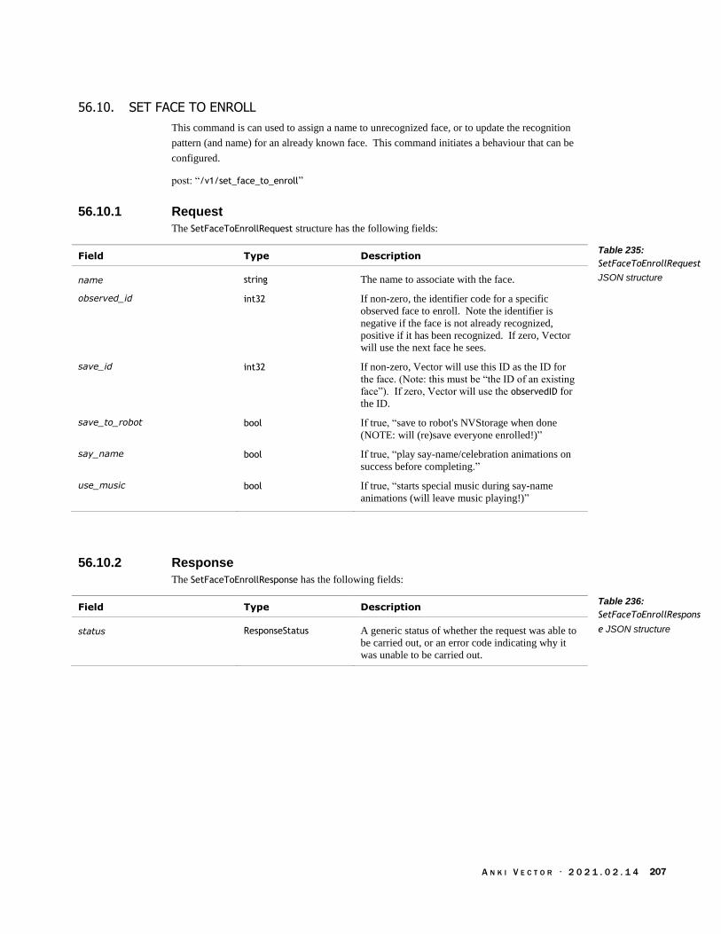
A N K I V E C T O R · 2 0 2 1 . 0 2 . 1 4 207
56.10. SET FACE TO ENROLL
This command is can used to assign a name to unrecognized face, or to update the recognition
pattern (and name) for an already known face. This command initiates a behaviour that can be
configured.
post: “/v1/set_face_to_enroll”
56.10.1 Request
The SetFaceToEnrollRequest structure has the following fields:
Field Type Description
name string The name to associate with the face.
observed_id int32 If non-zero, the identifier code for a specific
observed face to enroll. Note the identifier is
negative if the face is not already recognized,
positive if it has been recognized. If zero, Vector
will use the next face he sees.
save_id int32 If non-zero, Vector will use this ID as the ID for
the face. (Note: this must be “the ID of an existing
face”). If zero, Vector will use the observedID for
the ID.
save_to_robot bool If true, “save to robot's NVStorage when done
(NOTE: will (re)save everyone enrolled!)”
say_name bool If true, “play say-name/celebration animations on
success before completing.”
use_music bool If true, “starts special music during say-name
animations (will leave music playing!)”
56.10.2 Response
The SetFaceToEnrollResponse has the following fields:
Field Type Description
status ResponseStatus A generic status of whether the request was able to
be carried out, or an error code indicating why it
was unable to be carried out.
Table 235:
SetFaceToEnrollRequest
JSON structure
Table 236:
SetFaceToEnrollRespons
e JSON structure
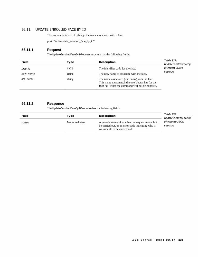
A N K I V E C T O R · 2 0 2 1 . 0 2 . 1 4 208
56.11. UPDATE ENROLLED FACE BY ID
This command is used to change the name associated with a face.
post: “/v1/update_enrolled_face_by_id”
56.11.1 Request
The UpdateEnrolledFaceByIDRequest structure has the following fields:
Field Type Description
face_id int32 The identifier code for the face.
new_name string The new name to associate with the face.
old_name string The name associated (until now) with the face.
This name must match the one Vector has for the
face_id. If not the command will not be honored.
56.11.2 Response
The UpdateEnrolledFaceByIDResponse has the following fields:
Field Type Description
status ResponseStatus A generic status of whether the request was able to
be carried out, or an error code indicating why it
was unable to be carried out.
Table 237:
UpdateEnrolledFaceByI
DRequest JSON
structure
Table 238:
UpdateEnrolledFaceByI
DResponse JSON
structure

A N K I V E C T O R · 2 0 2 1 . 0 2 . 1 4 209
57. FEATURES & ENTITLEMENTS
Vector has granular features that can be enabled and disabled thru the use of feature flags. This
section describes the queries related to list Vector’s features flags, and their state. For a description
of feature flags, see Chapter 31 Settings, Preferences, Features, and Statistics. For a list of the
features, and a description of each, see Appendix I, Table 636: The features.
Note: the API does not include the ability to enable a feature.
Note: For AI behaviour “features” see section 46.2.1 FeatureStatus.
57.1. ENUMERATIONS
57.1.1 UserEntitlement
The UserEntitlement enumeration has the following named values:
Name Value Description
KICKSTARTER_EYES 0 Note: This was an entitlement that was explored,
but not used.
Table 239:
UserEntitlement
Enumeration

A N K I V E C T O R · 2 0 2 1 . 0 2 . 1 4 210
57.2. GET FEATURE FLAG
Request the current setting of a feature flag.
post: “/v1/feature_flag”
57.2.1 Request
The FeatureFlagRequest message has the following fields:
Field Type Description
feature_name string The name of the feature; this feature name should
be one of those listed in response to Get Feature
Flag List (section 57.3). See Appendix I, Table
636: The features
57.2.2 Response
The FeatureFlagResponse type has the following fields:
Field Type Description
feature_enabled bool True if the feature is enabled, false if not
status ResponseStatus A generic status of whether the request was able to
be carried out, or an error code indicating why it
was unable to be carried out.
valid_feature bool True if the given feature name is a valid name of a
feature; false if not.
Table 240:
FeatureFlagRequest
JSON structure
Table 241:
FeatureFlagResponse
JSON structure

A N K I V E C T O R · 2 0 2 1 . 0 2 . 1 4 211
57.3. GET FEATURE FLAG LIST
Request the list of the current feature flags. Note: to see which flags are enabled, use the Get
Feature Flag command (section 57.2).
post: “/v1/feature_flag_list”
57.3.1 Request
The following is streamed… to the robot?
Field Type Description
request_list string
57.3.2 Response
The FeatureFlagListResponse type has the following fields:
Field Type Description
list string[] An array of the feature flags; see Appendix I, Table
636: The features for a description
status ResponseStatus A generic status of whether the request was able to
be carried out, or an error code indicating why it
was unable to be carried out.
Table 242:
FeatureFlagListRequest
JSON structure
Table 243:
FeatureFlagListRespons
e JSON structure
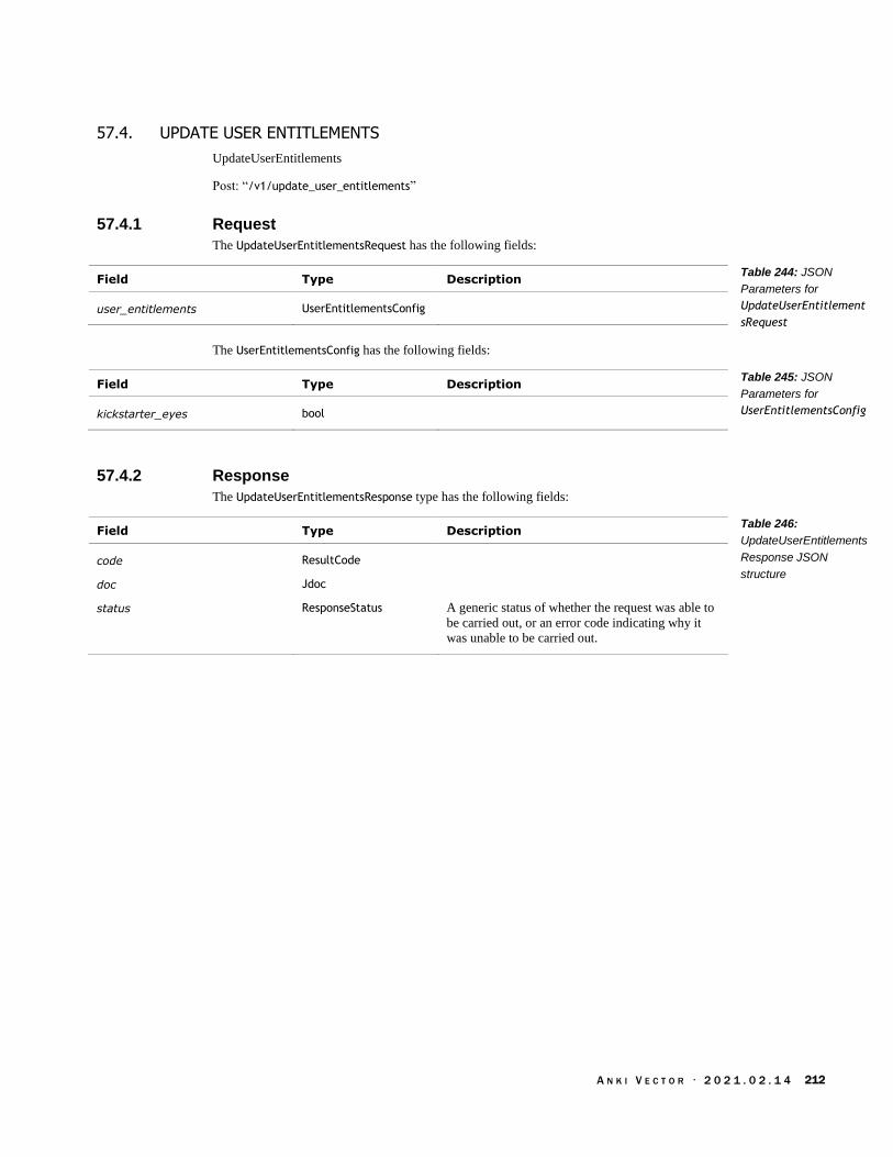
A N K I V E C T O R · 2 0 2 1 . 0 2 . 1 4 212
57.4. UPDATE USER ENTITLEMENTS
UpdateUserEntitlements
Post: “/v1/update_user_entitlements”
57.4.1 Request
The UpdateUserEntitlementsRequest has the following fields:
Field Type Description
user_entitlements UserEntitlementsConfig
The UserEntitlementsConfig has the following fields:
Field Type Description
kickstarter_eyes bool
57.4.2 Response
The UpdateUserEntitlementsResponse type has the following fields:
Field Type Description
code ResultCode
doc Jdoc
status ResponseStatus A generic status of whether the request was able to
be carried out, or an error code indicating why it
was unable to be carried out.
Table 244: JSON
Parameters for
UpdateUserEntitlement
sRequest
Table 245: JSON
Parameters for
UserEntitlementsConfig
Table 246:
UpdateUserEntitlements
Response JSON
structure

A N K I V E C T O R · 2 0 2 1 . 0 2 . 1 4 213
58. IMAGE PROCESSING
This section describes camera setting, and properties, and retrieve pictures/video stream. See also
section 56 Faces, for detecting and recognizing faces, and enabling the features
58.1. ENUMERATIONS
58.1.1 ImageEncoding
The ImageEncoding is used to describe the format of the image data contained in the chunk. The
enumeration has the following named values:
Name Value Description
NONE_IMAGE_ENCODING 0 Image is not encoded. TBD: does this mean no
image?
RAW_GRAY 1 “No compression”
RAW_RGB 2 “no compression, just [RGBRGBRG...]”
YUYV 3
YUV420SP 4
BAYER 5
JPEG_GRAY 6
JPEG_COLOR 7
JPEG_COLOR_HALF_WIDTH 8
JPEG_MINIMIZED_GRAY 9 “Minimized grayscale JPEG - no header, no footer,
no byte stuffing”
JPEG_MINIMIZED_COLOR 10 “Minimized grayscale JPEG – no header, no footer,
no byte stuffing, with added color data.”
58.2. EVENTS
58.2.1 CameraSettingsUpdate
This CameraSettingsUpdate event is sent when the camera exposure settings change. This structure
has the following fields:
Field Type Units Description
auto_exposure_enabled bool
exposure_ms uint32 ms
gain float
Table 247:
ImageEncoding
Enumeration
Table 248:
CameraSettingsUpdate
parameters

A N K I V E C T O R · 2 0 2 1 . 0 2 . 1 4 214
58.2.2 RobotObservedMotion
This RobotObservedMotion event structure has the following fields:
Field Type Units Description
bottom_img_area float area fraction
“Area of the supporting region for the point, as a
fraction of the bottom region”
bottom_img_x int32 pixel “Pixel coordinate of the point in the image, relative
to top-left corner.”
bottom_img_y int32 pixel “Pixel coordinate of the point in the image, relative
to top-left corner.”
ground_area float area
fraction “Area of the supporting region for the point, as a
fraction of the ground ROI. If unable to map to the
ground, area=0.”
ground_x int32 mm “Coordinates of the point on the ground, relative to
robot, in mm.”
ground_y int32 mm “Coordinates of the point on the ground, relative to
robot, in mm.”
img_area float area fraction
“Area of the supporting region for the point, as a
fraction of the image”
img_x int32 pixel “Pixel coordinate of the point in the image, relative
to top-left corner.”
img_y int32 pixel “Pixel coordinate of the point in the image, relative
to top-left corner.”
left_img_area float area
fraction “Area of the supporting region for the point, as a
fraction of the left region.”
left_img_x int32 pixel “Pixel coordinate of the point in the image, relative
to top-left corner.”
left_img_y int32 pixel “Pixel coordinate of the point in the image, relative
to top-left corner.”
right_img_area float area
fraction “Area of the supporting region for the point, as a
fraction of the right region.”
right_img_x int32 pixel “Pixel coordinate of the point in the image, relative
to top-left corner.”
right_img_y int32 pixel “Pixel coordinate of the point in the image, relative
to top-left corner.”
timestamp uint ms “Timestamp of the corresponding image”
top_img_area float area
fraction “Area of the supporting region for the point, as a
fraction of the top region”
top_img_x int32 pixel “Pixel coordinate of the point in the image, relative
to top-left corner.”
top_img_y int32 pixel “Pixel coordinate of the point in the image, relative
to top-left corner.”
Table 249:
RobotObservedMotion
parameters
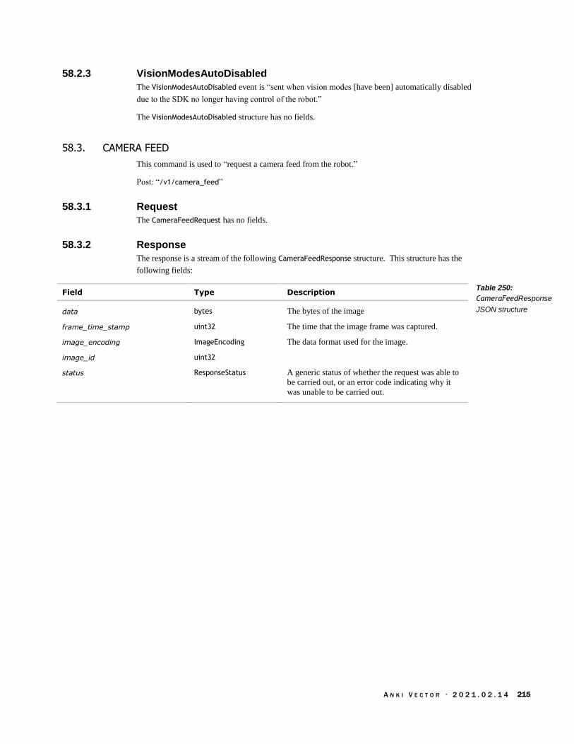
A N K I V E C T O R · 2 0 2 1 . 0 2 . 1 4 215
58.2.3 VisionModesAutoDisabled
The VisionModesAutoDisabled event is “sent when vision modes [have been] automatically disabled
due to the SDK no longer having control of the robot.”
The VisionModesAutoDisabled structure has no fields.
58.3. CAMERA FEED
This command is used to “request a camera feed from the robot.”
Post: “/v1/camera_feed”
58.3.1 Request
The CameraFeedRequest has no fields.
58.3.2 Response
The response is a stream of the following CameraFeedResponse structure. This structure has the
following fields:
Field Type Description
data bytes The bytes of the image
frame_time_stamp uint32 The time that the image frame was captured.
image_encoding ImageEncoding The data format used for the image.
image_id uint32
status ResponseStatus A generic status of whether the request was able to
be carried out, or an error code indicating why it
was unable to be carried out.
Table 250:
CameraFeedResponse
JSON structure

A N K I V E C T O R · 2 0 2 1 . 0 2 . 1 4 216
58.4. CAPTURE SINGLE IMAGE
“Request a single image to be captured and sent from the robot” to the application
Post: “/v1/capture_single_image”
58.4.1 Request
The CaptureSingleImageRequest has the following fields:
Field Type Description
enable_high_resolution bool True if the image should be capture in high
resolution; false to capture in 640x360 resolution.
Default: false. Optional.
Note: this field is only honoured in version 1.7 and
later of the software.
58.4.2 Response
The CaptureSingleImageResponse structure has the following fields:
Field Type Description
data bytes The bytes of the image
frame_time_stamp uint32 The time that the image frame was captured.
image_encoding ImageEncoding The data format used for the image.
image_id uint32
status ResponseStatus A generic status of whether the request was able to
be carried out, or an error code indicating why it
was unable to be carried out.
Table 251:
CaptureSingleImageReq
uest JSON structure
Table 252:
CaptureSingleImageRes
ponse JSON structure

A N K I V E C T O R · 2 0 2 1 . 0 2 . 1 4 217
58.5. ENABLE IMAGE STREAMING
“Toggle image streaming at the given resolution”
Post: “/v1/enable_image_streaming”
58.5.1 Request
The EnableImageStreamingRequest type has the following fields:
Field Type Description
enable bool True if Vector should send a stream of images from
the camera.
enable_high_resolution bool True if the image should be captured in high
resolution; false to capture in 640x360 resolution.
Default: false. Optional.
Note: this field is only honoured in version 1.7 and
later of the software.
58.5.2 Response
The EnableImageStreamingResponse has the following fields:
Field Type Description
status ResponseStatus A generic status of whether the request was able to
be carried out, or an error code indicating why it
was unable to be carried out.
Table 253:
EnableImageStreamingR
equest JSON structure
Table 254:
EnableImageStreamingR
esponse JSON structure

A N K I V E C T O R · 2 0 2 1 . 0 2 . 1 4 218
58.6. ENABLE MARKER DETECTION
This enables and disables the processing of custom marker symbols and generating events when a
marker symbol is seen. If enabled, when an marker symbol is see, the RobotObservedObject event
will be sent.
Note: The custom marker detection may remain internally enabled, even if disabled by the SDK,
“if another subscriber (including one internal to the robot) requests this vision mode be active.”
Post: “/v1/enable_marker_detection”
58.6.1 Request
The EnableMarkerDetectionRequest has the following fields:
Field Type Description
enable bool If true, enable search for maker symbols, and
generating events when they are detected,
58.6.2 Response
The EnableMarkerDetectionResponse has the following fields:
Field Type Description
status ResponseStatus A generic status of whether the request was able to
be carried out, or an error code indicating why it
was unable to be carried out.
Table 255: JSON
Parameters for
EnableMarkerDetection
Request
Table 256:
EnableMarkerDetection
Response JSON
structure

A N K I V E C T O R · 2 0 2 1 . 0 2 . 1 4 219
58.7. ENABLE MOTION DETECTION
Enables detecting visual motion, and sending RobotObservedMotion events in response.
Post: “/v1/enable_motion_detection”
58.7.1 Request
The EnableMotionDetectionRequest structure has the following fields:
Field Type Description
enable bool True if RobotObservedMotion events should be sent.
58.7.2 Response
The EnableMotionDetectiontResponse has the following fields:
Field Type Description
status ResponseStatus A generic status of whether the request was able to
be carried out, or an error code indicating why it
was unable to be carried out.
Table 257:
EnableMotionDetection
Request JSON structure
Table 258:
EnableMotionDetection
Response JSON
structure

A N K I V E C T O R · 2 0 2 1 . 0 2 . 1 4 220
58.8. GET CAMERA CONFIG
Requests the camera calibration and exposure settings. See Chapter 19 for more information on
these.
Post: “/v1/get_camera_config”
58.8.1 Request
The CameraConfigRequest has no fields.
58.8.2 Response
The CameraConfigResponse structure has the following fields:
Field Type Units Description
center_x float “The position of the optical center of projection
within the image. It will be close to the center of
the image, but adjusted based on the calibration of
the lens at the factory.”
center_y float
focal_length_x float The “focal length combined with pixel skew (as the
pixels aren't perfectly square), so there are subtly
different values for x and y.” focal_length_y float
fov_x float degree The full field of view along the x-axis.
fov_y float degree The full field of view along the y-axis.
max_camera_exposure_time_ms uint32 ms The maximum duration allowed for a frame
exposure.
min_camera_exposure_time_ms uint32 ms The minimum allowed duration for a frame
exposure.
max_camera_gain float The maximum allowed camera gain setting.
min_camera_gain float The minimum allowed camera gain setting.
58.9. IS IMAGE STREAMING ENABLED
This command is used to inquire “whether or not image streaming is enabled on the robot”
Post: “/v1/is_image_streaming_enabled”
58.9.1 Request
The IsImageStreamingRequest has no fields.
58.9.2 Response
The IsImageStreamingResponse “indicates whether or not image streaming is enabled on the robot.”
The structure has the following fields:
Field Type Description
enable bool True if image streaming is enabled, false otherwise
Table 259:
CameraConfigResponse
JSON structure
Table 260:
IsImageStreamingRespo
nse JSON structure

A N K I V E C T O R · 2 0 2 1 . 0 2 . 1 4 221
58.10. SET CAMERA SETTINGS
This command is used to change the camera exposure settings.
Post: “/v1/set_camera_config”
58.10.1 Request
The SetCameraSettingsRequest has the following fields:
Field Type Units Description
auto_exposure_enabled bool True if the camera suhould use auto-exposure
mode.
exposure_ms uint32 ms The requested duration of exposure, when in
manual settings.
gain float
58.10.2 Response
The SetCameraSettingsResponse structure has the following fields:
Field Type Description
status ResponseStatus A generic status of whether the request was able to
be carried out, or an error code indicating why it
was unable to be carried out.
status_string string
Table 261:
SetCameraSettings
parameters
Table 262:
SetCameraSettingsResp
onse JSON structure

A N K I V E C T O R · 2 0 2 1 . 0 2 . 1 4 222
59. INTERACTIONS WITH OBJECTS
These commands are used to interact with faces and objects. These initiate behaviours.
Some behaviours can be assigned a tag that can be used to cancel it later.
Some behaviours accept a parameter to modify their motion profile.
Behaviour results value
Actions
Actions can be assigned a tag that can be used to cancel it later.
Action results value
See also section 46 Actions and Behaviour, and section 53 Cube
59.1. STRUCTURES
59.1.1 PathMotionProfile
This structure contains “all the information relevant to how a path should be modified or
traversed.”
Field Type Units Description
accel_mmps2 float mm/sec2 How fast Vector should accelerate to achieve the
target speed.
decel_mmps2 float mm/sec2 How fast Vector should decelerate to the target
speed.
is_custom bool
dock_accel_mmps2 float mm/sec2 How fast Vector should accelerate when
performing the docking procedure.
dock_decel_mmps2 float mm/sec2 How fast Vector should decelerate when
performing the docking procedure.
dock_speed_mmps float mm/sec The speed that Vector should perform the docking
procedure at.
point_turn_accel_mmps2 float mm/sec2 How fast Vector should accelerate when turning (in
place).
point_turn_decel_mmps2 float mm/sec2 How fast Vector should decelerate when turning (in
place).
point_turn_speed_mmps float mm/sec The speed that Vector should perform a turn (in
place).
reverse_speed_mmps float mm/sec How fast Vector should moved when backing up
speed_mmps float mm/sec The speed that Vector should move along the path
Table 263:
PathMotionProfile
JSON structure
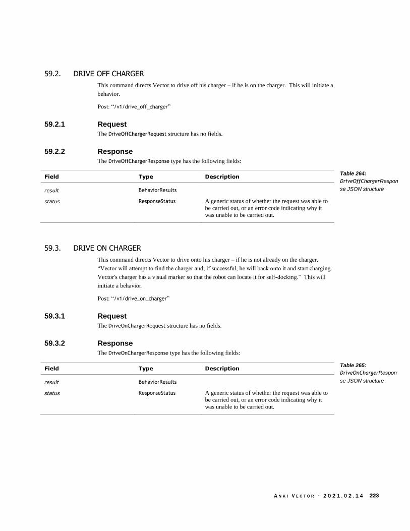
A N K I V E C T O R · 2 0 2 1 . 0 2 . 1 4 223
59.2. DRIVE OFF CHARGER
This command directs Vector to drive off his charger – if he is on the charger. This will initiate a
behavior.
Post: “/v1/drive_off_charger”
59.2.1 Request
The DriveOffChargerRequest structure has no fields.
59.2.2 Response
The DriveOffChargerResponse type has the following fields:
Field Type Description
result BehaviorResults
status ResponseStatus A generic status of whether the request was able to
be carried out, or an error code indicating why it
was unable to be carried out.
59.3. DRIVE ON CHARGER
This command directs Vector to drive onto his charger – if he is not already on the charger.
“Vector will attempt to find the charger and, if successful, he will back onto it and start charging.
Vector's charger has a visual marker so that the robot can locate it for self-docking.” This will
initiate a behavior.
Post: “/v1/drive_on_charger”
59.3.1 Request
The DriveOnChargerRequest structure has no fields.
59.3.2 Response
The DriveOnChargerResponse type has the following fields:
Field Type Description
result BehaviorResults
status ResponseStatus A generic status of whether the request was able to
be carried out, or an error code indicating why it
was unable to be carried out.
Table 264:
DriveOffChargerRespon
se JSON structure
Table 265:
DriveOnChargerRespon
se JSON structure

A N K I V E C T O R · 2 0 2 1 . 0 2 . 1 4 224
59.4. GO TO OBJECT
“Tell Vector to drive to the specified object” (i.e. his cube). Note: custom objects “are not
supported.” This initiates an action.
59.4.1 Request
The GoToObjectRequest structure has the following fields:
Field Type Units Description
id_tag int32 This is an action tag that can be assigned to this
request and used later to cancel the action.
Optional.
motion_prof PathMotionProfile Optional.
num_retries int32 The maximum number of times to attempt to reach
the object. A retry is attempted if Vector is unable
to reach the target object.
object_id int32 The identifier of the object to drive to. Note:
custom objects “are not supported”
distance_from_object_origin_mm float mm “The distance from the object to stop. This is the
distance between the origins. For instance, the
distance from the robot's origin (between Vector's
two front wheels) to the cube's origin (at the center
of the cube) is ~40mm.”
use_pre_dock_pose bool Set this to false
59.4.2 Response
The GoToObjectResponse is sent to indicate whether the action successfully completed or not. This
structure has the following fields:
Field Type Description
result ActionResult An error code indicating the success of the action,
the detailed reason why it failed, or that the action
is still being carried out.
status ResponseStatus A generic status of whether the request was able to
be carried out, or an error code indicating why it
was unable to be carried out.
Table 266:
GoToObjectRequest
JSON structure
Table 267:
GoToObjectResponse
JSON structure

A N K I V E C T O R · 2 0 2 1 . 0 2 . 1 4 225
59.5. TURN TOWARDS FACE
“Tell Vector to turn towards” the specified face. This initiates an action.
59.5.1 Request
The TurnTowardsFaceRequest structure has the following fields:
Field Type Description
face_id int32 The identifier of the face to look for
id_tag int32 This is an action tag that can be assigned to this
request and used later to cancel the action.
Optional.
max_turn_angle_rad float Recommend value of 180°
num_retries int32 Maximum of times to attempt to reach the object.
A retry is attempted if Vector is unable to reach the
target object.
59.5.2 Response
The TurnTowardsFaceResponse is sent to indicate whether the action successfully completed or not.
This structure has the following fields:
Field Type Description
result ActionResult An error code indicating the success of the action,
the detailed reason why it failed, or that the action
is still being carried out.
status ResponseStatus A generic status of whether the request was able to
be carried out, or an error code indicating why it
was unable to be carried out.
Table 268:
TurnTowardsFaceReque
st JSON structure
Table 269:
TurnTowardsFaceRespo
nse JSON structure

A N K I V E C T O R · 2 0 2 1 . 0 2 . 1 4 226
60. JDOCS
This section discusses the commands for “Jdocs” (short for “JSON Documents”), which are JSON
objects that are passed to Vic-Engine and then onto Vic-Cloud. See the next chapter for interactions
with a remote Jdocs server, using a sibling protocol.
60.1. ENUMERATIONS
60.1.1 JdocType
The JdocType enumeration has the following named values:
Name Value Description
ACCOUNT_SETTINGS 2 Refers to the owner’s account settings
ROBOT_LIFETIME_STATS 1 Refers to the robot’s settings (owner preferences)
ROBOT_SETTINGS 0 Refers to the robot’s lifetime stats.
USER_ENTITLEMENTS 3 Refers to the owner’s entitlements.
Items of these types are described in more detail in Chapter 31.
60.2. STRUCTURES
60.2.1 Jdoc
The Jdoc type has the following fields:
Field Type Description
client_meta string Probably an empty string.
doc_version uint64 A number used to uniquely identify changes to the
setting structure, and be able to tell which ones is
the more recent settings. Most often this is the
number of times that the settings have been
changed.
fmt_version uint64 The version number of the jdoc structure schema;
this is always 1.
json_doc string The jdoc structure serialized as a string.
60.2.2 NamedJdoc
The NamedJdoc type has the following fields:
Field Type Description
doc Jdoc The JSON structure and meta-data about the
document
jdoc_type JdocType The type of document provided in “doc”
Table 270: JdocType
Enumeration
Table 271: Jdoc JSON
structure
Table 272: JSON
NamedJdoc structure

A N K I V E C T O R · 2 0 2 1 . 0 2 . 1 4 227
60.3. EVENTS
60.3.1 JdocsChanged
The JdocsChanged message is sent when a Jdoc objct has been changed. This message has the
following fields:
Field Type Description
jdoc_types JdocType[] The list of Jdoc’s to retrieve.
60.4. PULL JDOCS
This command is used to retrieve a Jdocs object.
Post: “/v1/pull_jdocs”
60.4.1 Request
The PullJdocsRequest has the following fields:
Field Type Description
jdoc_types JdocType[] Each of the retrieved Jdoc objects.
60.4.2 Response
The PullJdocResponse has the following fields:
Field Type Description
named_jdocs NamedJdoc[]
status ResponseStatus A generic status of whether the request was able to
be carried out, or an error code indicating why it
was unable to be carried out.
Table 273: JSON
JdocsChanged request
structure
Table 274: JSON
PullJdocsRequest
structure
Table 275: JSON
PullJdocsResponse
structure
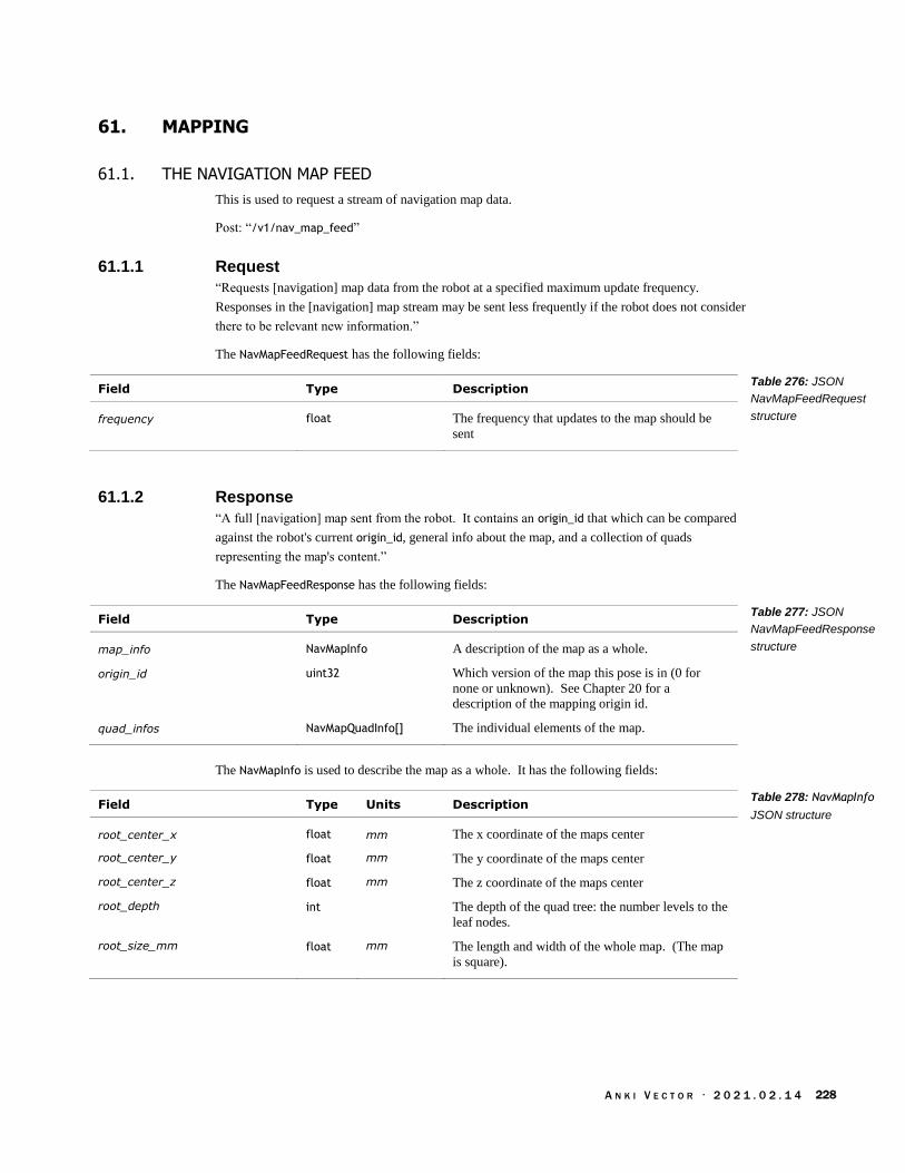
A N K I V E C T O R · 2 0 2 1 . 0 2 . 1 4 228
61. MAPPING
61.1. THE NAVIGATION MAP FEED
This is used to request a stream of navigation map data.
Post: “/v1/nav_map_feed”
61.1.1 Request
“Requests [navigation] map data from the robot at a specified maximum update frequency.
Responses in the [navigation] map stream may be sent less frequently if the robot does not consider
there to be relevant new information.”
The NavMapFeedRequest has the following fields:
Field Type Description
frequency float The frequency that updates to the map should be
sent
61.1.2 Response
“A full [navigation] map sent from the robot. It contains an origin_id that which can be compared
against the robot's current origin_id, general info about the map, and a collection of quads
representing the map's content.”
The NavMapFeedResponse has the following fields:
Field Type Description
map_info NavMapInfo A description of the map as a whole.
origin_id uint32 Which version of the map this pose is in (0 for
none or unknown). See Chapter 20 for a
description of the mapping origin id.
quad_infos NavMapQuadInfo[] The individual elements of the map.
The NavMapInfo is used to describe the map as a whole. It has the following fields:
Field Type Units Description
root_center_x float mm The x coordinate of the maps center
root_center_y float mm The y coordinate of the maps center
root_center_z float mm The z coordinate of the maps center
root_depth int The depth of the quad tree: the number levels to the
leaf nodes.
root_size_mm float mm The length and width of the whole map. (The map
is square).
Table 276: JSON
NavMapFeedRequest
structure
Table 277: JSON
NavMapFeedResponse
structure
Table 278: NavMapInfo
JSON structure

A N K I V E C T O R · 2 0 2 1 . 0 2 . 1 4 229
The NavMapQuadInfo is “an individual sample of Vector's [navigation] map. This quad's size will
vary and depends on the resolution the map requires to effectively identify boundaries in the
environment.” It has the following fields:
Field Type Description
color_rgba uint32 Suggested color for the area of the map, used when
visualizing the map.
content NavNodeContentType A tag of what Vector has identified as located in
this area.
depth uint32 The depth within the tree.
“Every tile in the [navigation] map will be tagged with a content key referring to the different
environmental elements that Vector can identify.” The NavNodeContentType is used to represent
the kind of environmental element.
Name Value Description
NAV_NODE_UNKNOWN 0 It is not known what is in the area
NAV_NODE_CLEAR_OF_OBSTACLE 1 Vector has confirmed that an obstacle is not present
in this area.
NAV_NODE_CLEAR_OF_CLIFF 2 Vector has confirmed that an obstacle is not present
in this area.
NAV_NODE_OBSTACLE_CUBE 3 The cube is in this area
NAV_NODE_OBSTACLE_PROXIMITY 4 The time of flight sensor (the proximity sensor)
indicates that there is an obstacle in this area.
NAV_NODE_OBSTACLE_PROXIMITY_EXPLORED 5
NAV_NODE_OBSTACLE_UNRECOGNIZED 6
NAV_NODE_CLIFF 7 There is a cliff here
NAV_NODE_INTERESTING_EDGE 8
NAV_NODE_NON_INTERESTING_EDGE 9
Table 279:
NavMapQuadInfo
structure
Table 280:
NavNodeContentType
Enumeration
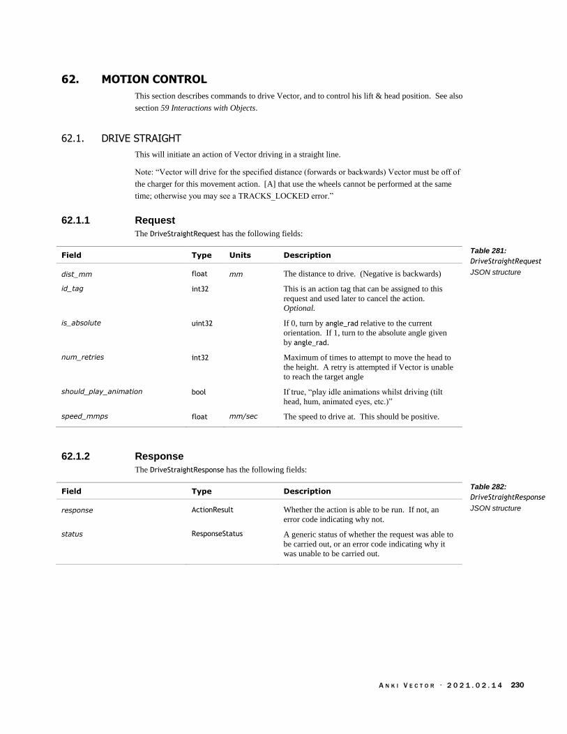
A N K I V E C T O R · 2 0 2 1 . 0 2 . 1 4 230
62. MOTION CONTROL
This section describes commands to drive Vector, and to control his lift & head position. See also
section 59 Interactions with Objects.
62.1. DRIVE STRAIGHT
This will initiate an action of Vector driving in a straight line.
Note: “Vector will drive for the specified distance (forwards or backwards) Vector must be off of
the charger for this movement action. [A] that use the wheels cannot be performed at the same
time; otherwise you may see a TRACKS_LOCKED error.”
62.1.1 Request
The DriveStraightRequest has the following fields:
Field Type Units Description
dist_mm float mm The distance to drive. (Negative is backwards)
id_tag int32 This is an action tag that can be assigned to this
request and used later to cancel the action.
Optional.
is_absolute uint32 If 0, turn by angle_rad relative to the current
orientation. If 1, turn to the absolute angle given
by angle_rad.
num_retries int32 Maximum of times to attempt to move the head to
the height. A retry is attempted if Vector is unable
to reach the target angle
should_play_animation bool If true, “play idle animations whilst driving (tilt
head, hum, animated eyes, etc.)”
speed_mmps float mm/sec The speed to drive at. This should be positive.
62.1.2 Response
The DriveStraightResponse has the following fields:
Field Type Description
response ActionResult Whether the action is able to be run. If not, an
error code indicating why not.
status ResponseStatus A generic status of whether the request was able to
be carried out, or an error code indicating why it
was unable to be carried out.
Table 281:
DriveStraightRequest
JSON structure
Table 282:
DriveStraightResponse
JSON structure

A N K I V E C T O R · 2 0 2 1 . 0 2 . 1 4 231
62.2. DRIVE WHEELS
Sets the speed and acceleration for Vector's wheel motors.
62.2.1 Request
The DriveWheelsRequest has the following fields:
Field Type Units Description
left_wheel_mmps float mm/sec The initial speed to set the left wheel to.
left_wheel_mmps2 float mm/sec2 How fast to increase the speed of the left wheel.
right_wheel_mmps float mm/sec The initial speed to set the right wheel to.
right_wheel_mmps2 float mm/sec2 How fast to increase the speed of the right wheel.
To unlock the wheels, set all values to 0.
62.2.2 Response
The DriveWheelsResponse has the following fields:
Field Type Description
status ResponseStatus A generic status of whether the request was able to
be carried out, or an error code indicating why it
was unable to be carried out.
Table 283:
DriveWheelsRequest
JSON structure
Table 284:
DriveWheelsResponse
JSON structure

A N K I V E C T O R · 2 0 2 1 . 0 2 . 1 4 232
62.3. GO TO POSE
“Tells Vector to drive to the specified pose and orientation.” This will initiate an action. “In
navigating to the requested pose, Vector will use path planning. “Since the robot understands
position by monitoring its tread movement, it does not understand movement in the z axis. This
means that the only applicable elements of pose in this situation are position.x position.y and
rotation.angle_z.
“Note that actions that use the wheels cannot be performed at the same time, otherwise you may
see a TRACKS_LOCKED error.”
Post: “/v1/go_to_pose”
62.3.1 Request
The GoToPoseRequest structure has the following fields:
Field Type Units Description
id_tag int32 This is an action tag that can be assigned to this
request and used later to cancel the action.
Optional.
motion_prof PathMotionProfile
num_retries int32 Maximum of times to attempt to reach the pose. A
retry is attempted if Vector is unable to reach the
target pose.
rad float radians The angle to change orientation to.
x_mm float mm The x-coordinate of the position to move to.
y_mm float mm The y-coordinate of the position to move to.
62.3.2 Response
The GoToPoseResponse is sent to indicate whether the action successfully completed or not. This
structure has the following fields:
Field Type Description
result ActionResult An error code indicating the success of the action,
the detailed reason why it failed, or that the action
is still being carried out.
status ResponseStatus A generic status of whether the request was able to
be carried out, or an error code indicating why it
was unable to be carried out.
Table 285:
GoToPoseRequest JSON
structure
Table 286:
GoToPoseResponse
JSON structure
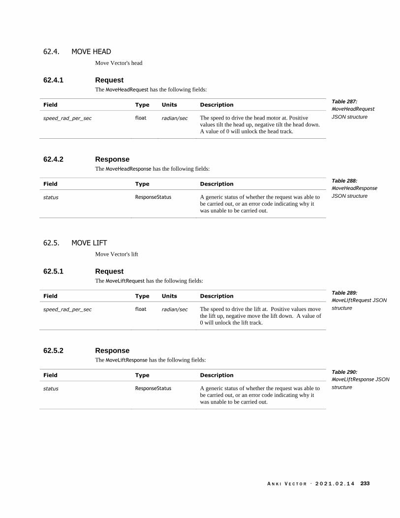
A N K I V E C T O R · 2 0 2 1 . 0 2 . 1 4 233
62.4. MOVE HEAD
Move Vector's head
62.4.1 Request
The MoveHeadRequest has the following fields:
Field Type Units Description
speed_rad_per_sec float radian/sec The speed to drive the head motor at. Positive
values tilt the head up, negative tilt the head down.
A value of 0 will unlock the head track.
62.4.2 Response
The MoveHeadResponse has the following fields:
Field Type Description
status ResponseStatus A generic status of whether the request was able to
be carried out, or an error code indicating why it
was unable to be carried out.
62.5. MOVE LIFT
Move Vector's lift
62.5.1 Request
The MoveLiftRequest has the following fields:
Field Type Units Description
speed_rad_per_sec float radian/sec The speed to drive the lift at. Positive values move
the lift up, negative move the lift down. A value of
0 will unlock the lift track.
62.5.2 Response
The MoveLiftResponse has the following fields:
Field Type Description
status ResponseStatus A generic status of whether the request was able to
be carried out, or an error code indicating why it
was unable to be carried out.
Table 287:
MoveHeadRequest
JSON structure
Table 288:
MoveHeadResponse
JSON structure
Table 289:
MoveLiftRequest JSON
structure
Table 290:
MoveLiftResponse JSON
structure

A N K I V E C T O R · 2 0 2 1 . 0 2 . 1 4 234
62.6. SET HEAD ANGLE
This will initiate an action to move Vector’s head to a given angle.
62.6.1 Request
The SetHeadAngleRequest has the following fields:
Field Type Units Description
accel_rad_per_sec2 float radian/sec2 How fast to increase the speed the head is moving
at. Recommended value: 10 radians/sec2
angle_rad float radians The target angle to move Vector’s head to. This
should be in the range -22.0° to 45.0°.
duration_sec float sec “Time for Vector's head to move in seconds. A
value of zero will make Vector try to do it as
quickly as possible.”
id_tag int32 This is an action tag that can be assigned to this
request and used later to cancel the action.
Optional.
max_speed_rad_per_sec float radian/sec The maximum speed to move the head. (This
clamps the speed from further acceleration.)
Recommended value: 10 radians/sec
num_retries int32 count Maximum of times to attempt to move the head to
the height. A retry is attempted if Vector is unable
to reach the target angle
62.6.2 Response
The SetHeadAngleResponse has the following fields:
Field Type Description
response ActionResult Whether the action is able to be run. If not, an
error code indicating why not.
status ResponseStatus A generic status of whether the request was able to
be carried out, or an error code indicating why it
was unable to be carried out.
Table 291:
SetHeadAngleRequest
JSON structure
Table 292:
SetHeadAngleResponse
JSON structure
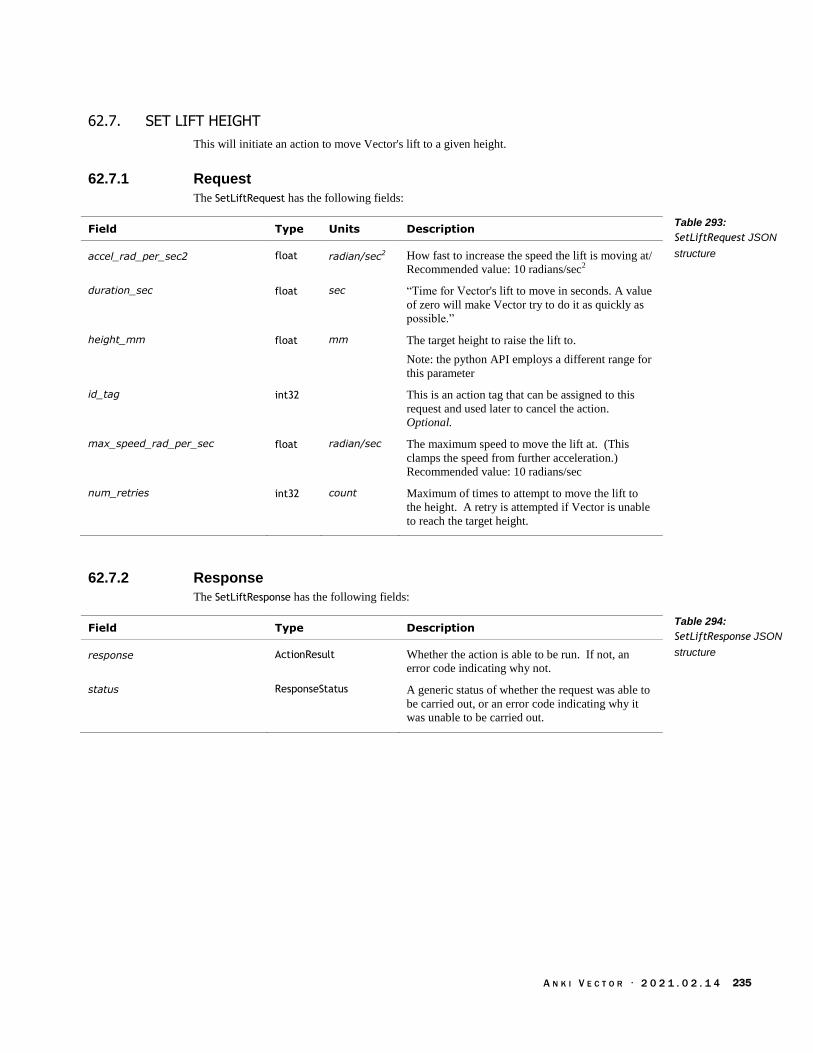
A N K I V E C T O R · 2 0 2 1 . 0 2 . 1 4 235
62.7. SET LIFT HEIGHT
This will initiate an action to move Vector's lift to a given height.
62.7.1 Request
The SetLiftRequest has the following fields:
Field Type Units Description
accel_rad_per_sec2 float radian/sec2 How fast to increase the speed the lift is moving at/
Recommended value: 10 radians/sec2
duration_sec float sec “Time for Vector's lift to move in seconds. A value
of zero will make Vector try to do it as quickly as
possible.”
height_mm float mm The target height to raise the lift to.
Note: the python API employs a different range for
this parameter
id_tag int32 This is an action tag that can be assigned to this
request and used later to cancel the action.
Optional.
max_speed_rad_per_sec float radian/sec The maximum speed to move the lift at. (This
clamps the speed from further acceleration.)
Recommended value: 10 radians/sec
num_retries int32 count Maximum of times to attempt to move the lift to
the height. A retry is attempted if Vector is unable
to reach the target height.
62.7.2 Response
The SetLiftResponse has the following fields:
Field Type Description
response ActionResult Whether the action is able to be run. If not, an
error code indicating why not.
status ResponseStatus A generic status of whether the request was able to
be carried out, or an error code indicating why it
was unable to be carried out.
Table 293:
SetLiftRequest JSON
structure
Table 294:
SetLiftResponse JSON
structure
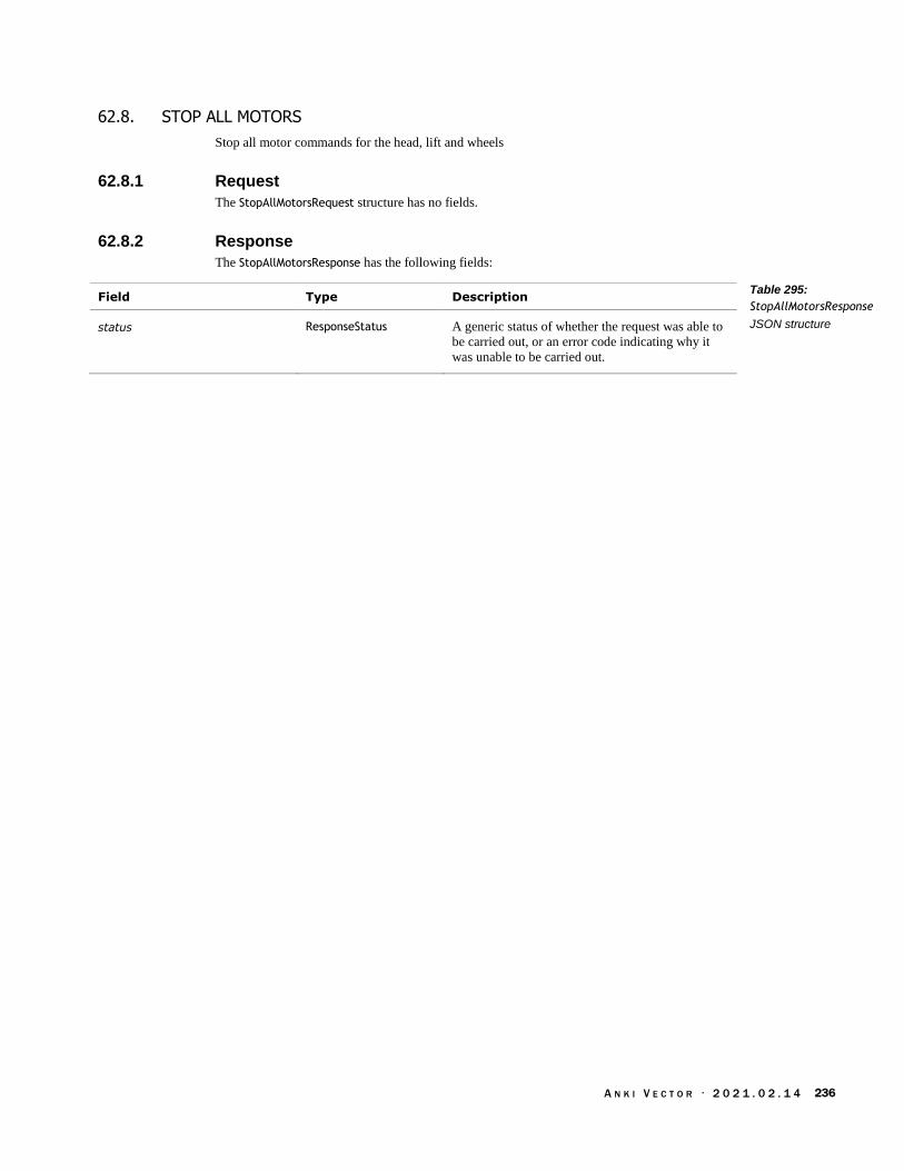
A N K I V E C T O R · 2 0 2 1 . 0 2 . 1 4 236
62.8. STOP ALL MOTORS
Stop all motor commands for the head, lift and wheels
62.8.1 Request
The StopAllMotorsRequest structure has no fields.
62.8.2 Response
The StopAllMotorsResponse has the following fields:
Field Type Description
status ResponseStatus A generic status of whether the request was able to
be carried out, or an error code indicating why it
was unable to be carried out.
Table 295:
StopAllMotorsResponse
JSON structure

A N K I V E C T O R · 2 0 2 1 . 0 2 . 1 4 237
62.9. TURN IN PLACE
This command initiates an action to turn Vector around its current position.
Note: “Vector must be off of the charger for this movement action. Note that actions that use the
wheels cannot be performed at the same time, otherwise you may see a TRACKS_LOCKED
error.”
62.9.1 Request
The TurnInPlaceRequest has the following fields:
Field Type Units Description
accel_rad_per_sec2 float radian/sec2 How fast to increase the speed the body is moving
at
angle_rad float radians If is_absolute is 0, turn relative to the current
heading by this number of radians; positive means
turn left, negative is turn right. Otherwise, turn to
the absolute orientation given by this angle.
id_tag int32 This is an action tag that can be assigned to this
request and used later to cancel the action.
Optional.
is_absolute uint32 If 0, turn by angle_rad relative to the current
orientation. If 1, turn to the absolute angle given
by angle_rad.
num_retries int32 count Maximum of times to attempt to turn to the target
angle. A retry is attempted if Vector is unable to
reach the target angle.
speed_rad_per_sec float radian/sec The speed to move around the arc.
tol_rad float count “The angular tolerance to consider the action
complete (this is clamped to a minimum of 2
degrees internally).”
62.9.2 Response
The TurnInPlaceResponse has the following fields:
Field Type Description
response ActionResult Whether the action is able to be run. If not, an
error code indicating why not.
status ResponseStatus A generic status of whether the request was able to
be carried out, or an error code indicating why it
was unable to be carried out.
Table 296:
TurnInPlaceRequest
JSON structure
Table 297:
TurnInPlaceResponse
JSON structure

A N K I V E C T O R · 2 0 2 1 . 0 2 . 1 4 238
63. MOTION SENSING AND ROBOT STATE
This section describes the structures and events that describe the sensed motions.
The values are given with respect to a “coordinate space is relative to Vector, where Vector's origin
is the point on the ground between Vector's two front wheels. The X axis is Vector's forward
direction, the Y axis is to Vector's left, and the Z axis is up.”
63.1. ENUMERATIONS
63.1.1 UnexpectedMovementSide
The UnexpectedMovementSide enumeration has the following named values:
Name Value Description
UNKOWN 0
FRONT 1
BACK 2
LEFT 3
RIGHT 4
63.1.2 UnexpectedMovementType
The UnexpectedMovementType enumeration has the following named values:
Name Value Description
TURNED_BUT_STOPPED 0
TURNED_IN_SAME_DIRECTION 1
TURNED_IN_OPPOSITE_DIRECTION
2
ROTATING_WITHOUT_MOTORS 3
63.2. STRUCTURES
63.2.1 AccelData
This structure is used to report the accelerometer readings, as part of the RobotState structure. The
accelerometer is located in Vector’s head, so its XYZ axes are not the same as Vector’s body axes.
When motionless, the accelerometer can be used to calculate the angle of Vectors head. The
AccelData has the following fields:
Field Type Units Description
x float mm/s2 The acceleration along the accelerometers X axis.
y float mm/s2 The acceleration along the accelerometers Y axis.
z float mm/s2 The acceleration along the accelerometers Z axis.
Table 298:
UnexpectedMovementSi
de Enumeration
Table 299:
UnexpectedMovementT
ype Enumeration
Table 300: AccelData
JSON structure

A N K I V E C T O R · 2 0 2 1 . 0 2 . 1 4 239
When at rest, there will be a constant 9810 mm/s2 downward acceleration from gravity. This most
likely will be distributed over multiple axes.
63.2.2 GyroData
This structure is used to report the gyroscope readings, as part of the RobotState structure. The
gryoscope is located in Vector’s head, so its XYZ axes are not the same as Vector’s body axes.
The GryroData has the following fields:
Field Type Units Description
x float radian/s The angular velocity around the X axis.
y float radian/s The angular velocity around the Y axis.
z float radian/s The angular velocity around the Z axis.
63.2.3 ProxData
This structure is used to report the “time of flight” proximity sensor readings, as part of the
RobotState structure.
“The proximity sensor is located near the bottom of Vector between the two front wheels, facing
forward. The reported distance describes how far in front of this sensor the robot feels an
obstacle is. The sensor estimates based on time-of-flight information within a field of view which
the engine resolves to a certain quality value.”
The distance measurement may not be valid. The sensor may be blocked Vector’s lift or the item
he is carying. Or the sensor may not have picked up anything significant. These are indicated by
“four additional flags are supplied by the engine to indicate whether this proximity data is
considered valid for the robot's internal pathfinding.” It is recommended that an application track
the most recent proximity data from the robot, and the most recent proximity data which did not
have the lift blocking.
The ProxData has the following fields:
Field Type Units Description
distance_mm uint32 mm The distance to the object (if any)
found_object bool True if “the sensor detected an object in the valid
operating range.”
is_lift_in_fov bool True if “Vector's lift (or an object in the lift) is
blocking the time-of-flight sensor. While the lift
will send clear proximity signals, it's not useful for
object detection.”
signal_quality float An estimate of the “reliability of the measurement.”
“The proximity sensor detects obstacles within a
given field of view; this value represents the
likelihood of the reported distance being a solid
surface.”
unobstructed bool True if “the sensor has confirmed it has not
detected anything up to its max range.” (The
opposite of found_object)
Table 301: GyroData
JSON structure
proximity sensor
Table 302: ProxData
JSON structure

A N K I V E C T O R · 2 0 2 1 . 0 2 . 1 4 240
63.2.4 TouchData
This structure is used to report the touch sensor readings, as part of the RobotState structure. The
TouchData has the following fields:
Field Type Units Description
is_being_touched bool True if Vector is currently being touched.
raw_touch_value uint32 “Raw input from the touch sensor.”
63.3. EVENTS
63.3.1 RobotState
The RobotState structure is periodically posted in an Event message. The structure has the
following fields:
Field Type Units Description
accel AccelData The accelerometer readings
carrying_object_id int32 -1 if no object is being carried. Otherwise the
identifier of the cube (or other object) being
carried.
carrying_object_on_top_id int32 Not supported
gyro GyroData The gyroscope readings
head_angle_rad float radian The angle of Vector’s head (how much it is tilted
up or down).
head_tracking_object_id int32 The identifier “of the object the head is tracking
to.” If no object is being tracked, this will be -1.
last_image_time_stamp uint32 “The robot's timestamp for the last image seen.”
The format is milliseconds since Vector’s epoch.
left_wheel_speed_mmps float mm/s The speed of Vector’s left wheel.
lift_height_mm float mm “Height of Vector's lift from the ground.”
localized_to_object_id int32 The identifier “of the object that the robot is
localized to.” If no object, this will be -1.
pose PoseStruct “The current pose (position and orientation) of
Vector.”
pose_angle_rad float radian “Vector's pose angle (heading in X-Y plane).”
pose_pitch_rad float radian “Vector's pose pitch (angle up/down).”
right_wheel_speed_mmps float mm/s The speed of Vector’s right wheel.
prox_data ProxData The time-of-flight proximity sensor readings.
status uint32 A bit map of active states of Vector; the bits are
described in the RobotStatus enumeration.
“This status provides a simple mechanism to, for
example, detect if any of Vector's motors are
moving, determine if Vector is being held, or if he
is on the charger.”
touch_data TouchData The touch sensor readings.
Table 303: TouchData
JSON structure
Table 304: RobotState
JSON structure

A N K I V E C T O R · 2 0 2 1 . 0 2 . 1 4 241
63.3.2 Unexpected Movement
The UnexpectedMovement structure is posted in an Event message when a movement is sensed, but
the robot had not intended it. The structure has the following fields:
Field Type Description
movement_side UnexpectedMovementSide
movement_type UnexpectedMovementType
timestamp uint32 The time that the movement was sensed. The
format is unix time: seconds since 1970, in UTC.
Table 305:
UnexpectedMovement
JSON structure

A N K I V E C T O R · 2 0 2 1 . 0 2 . 1 4 242
64. ON BOARDING
The section describes the command and events used to introduce Vector to his new human, and his
human to Vector’s features.
64.1. ENUMERATIONS
64.1.1 OnboardingPhase
The OnboardingPhase enumeration has the following named values:
Name Value Description
InvalidPhase 0
Default 1
LookAtPhone 2
WakeUp 3
LookAtUser 4
TeachWakeWord 5
TeachComeHere 6
TeachMeetVictor 7
64.1.2 OnboardingPhaseState
The OnboardingPhaseState enumeration has the following named values:
Name Value Description
PhaseInvalid 0
PhasePending 1
PhaseInProgress 2
PhaseComplete 3
Table 306:
OnboardingPhase
Enumeration
Table 307:
OnboardingPhaseState
Enumeration

A N K I V E C T O R · 2 0 2 1 . 0 2 . 1 4 243
64.2. EVENTS
The following are events related to onboarding.
64.2.1 Onboarding
The Onboarding event is sent as different stages of the onboarding process have been completed.
This structure has the following fields:
Field Type Description
onboarding_1p0_charging_info Onboarding1p0ChargingInfo
onbaording_state OnboardingState
onboarding_wakeup_finished {} This structure contains no fields.
64.2.2 Onboarding1p0ChargingInfo
This structure is used to report whether Vector needs to charge, and an estimated (or
recommended) duration. It is part of the Onboarding event structure. This structure has the
following fields:
Field Type Units Description
needs_to_charge bool If true, Vector needs to charge before onboarding
can continue.
on_charger bool If true, Vector is on his charger, and there is power
supplied to the charger.
suggested_charger_time float The estimated amount of time to charger Vector
before completing the onboarding process.
64.2.3 OnboardingState
The OnboardingState type has the following fields:
Field Type Description
stage OnboardingStages Where in the onboarding process we are
The OnboardingStages enumeration has the following named values:
Name Value Description
NotStarted 0 The onboarding process has not started yet.
TimedOut 1 The onboarding process has halted because an
operation timed out.
Complete 3 The onboarding has completed.
DevDoNothing 4
Table 308: Onboarding
JSON structure
Table 309:
Onboarding1p0ChargingI
nfoJSON structure
Table 310:
OnboardingState JSON
structure
Table 311:
OnboardingStages
Enumeration

A N K I V E C T O R · 2 0 2 1 . 0 2 . 1 4 244
64.3. ONBOARDING COMPLETE REQUEST
64.3.1 Request
The OnboardingCompleteRequest structure has no fields.
64.3.2 Response
The OnboardingCompleteResponse type has the following fields:
Field Type Description
completed bool True if the onboarding process has completed.
64.4. ONBOARDING INPUT
Post: “/v1/send_onboarding_input”
64.4.1 Request
The OnboardingInputRequest has one (and only one) of the following fields:
Field Type Description
onboarding_charge_info_request {} This is a request for charging information; it
contains no fields.
onboarding_complete_request {} This is a request to complete the onboarding; it
contains no fields.
onboarding_mark_complete_and_
exit
{} This contains no fields.
onboarding_restart {} This is a request to restart the onboarding process;
it contains no fields.
onboarding_skip_onboarding {} This is a request to skip the onboarding; it contains
no fields.
onboarding_phase_progress_requ
est
{} This contains no fields.
onboarding_set_phase_request OnboardingSetPhaseRequest
See below.
onboarding_wake_up_request {} This is a request to wake up Vector; it contains no
fields.
onboarding_wake_up_started_request
{} This contains no fields.
The OnboardingSetPhaseRequest type has the following fields:
Field Type Description
phase OnboardingPhase The desired phase to be in
Table 312:
OnboardingCompleteRe
sponse JSON structure
Table 313:
OnboardingInputReques
t JSON structure
Table 314:
OnboardingSetPhaseReq
uest JSON structure

A N K I V E C T O R · 2 0 2 1 . 0 2 . 1 4 245
64.4.2 Response
The OnboardingInputResponse has a status field one (and only one) of the remaining following
fields (which will correspond to the one sent in the request):
Field Type Description
onboarding_charge_info_response
OnboardingChargingInfoResponse
See below
onboarding_complete_response OnboardingCompleteResponse
See below
onboarding_phase_progress_resp
onse
{} See below
onboarding_set_phase_response OnboardingSetPhaseResponse
See below.
onboarding_wake_up_response OnboardingWakeupResponse
See below
onboarding_wake_up_started_res
ponse
OnboardingWakeupStartedResponse
status ResponseStatus A generic status of whether the request was able to
be carried out, or an error code indicating why it
was unable to be carried out.
ONBOARDINGCHARGINGINFORESPONSE
This structure is used to report whether Vector needs to charge, and an estimated (or suggested)
duration. It is part of the OnboardingInputResponse event structure. This structure has the
following fields:
Field Type Units Description
needs_to_charge bool If true, Vector needs to charge before onboarding
can continue.
on_charger bool If true, Vector is on his charger, and there is power
supplied to the charger.
required_charge_time float The estimated amount of time to charger Vector
before completing the onboarding process.
status ResponseStatus A generic status of whether the request was able to
be carried out, or an error code indicating why it
was unable to be carried out.
Note: this structure is similar to the Onboarding1p0ChargingInfo structure. That structures is older,
but retained as software had already been developed against it.
ONBOARDINGCOMPLETERESPONSE
The OnboardingCompleteResponse type has the following fields:
Field Type Description
completed bool True if the onboarding has completed
Table 315:
OnboardingInputRespon
se JSON structure
Table 316:
OnboardingInputRespon
se structure
Table 317:
OnboardingCompleteRe
sponse JSON structure
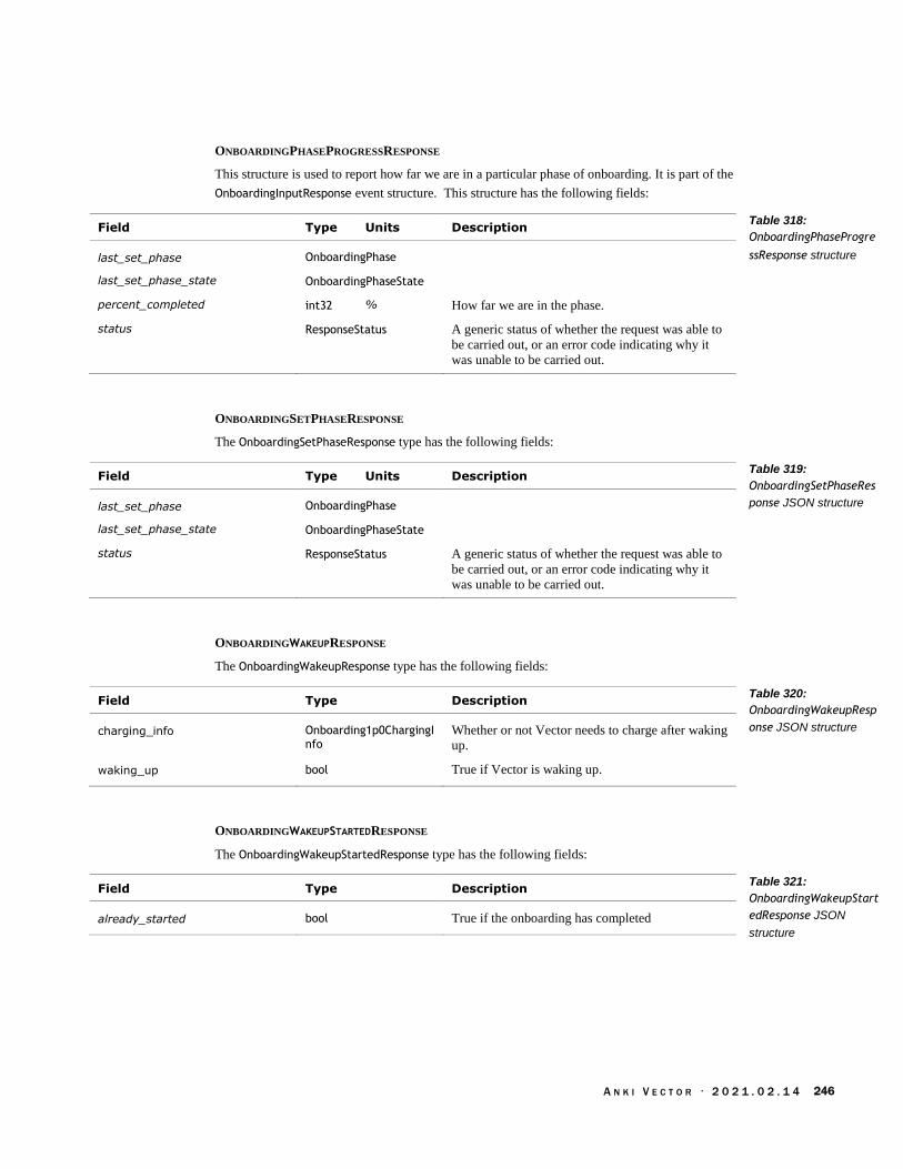
A N K I V E C T O R · 2 0 2 1 . 0 2 . 1 4 246
ONBOARDINGPHASEPROGRESSRESPONSE
This structure is used to report how far we are in a particular phase of onboarding. It is part of the
OnboardingInputResponse event structure. This structure has the following fields:
Field Type Units Description
last_set_phase OnboardingPhase
last_set_phase_state OnboardingPhaseState
percent_completed int32 % How far we are in the phase.
status ResponseStatus A generic status of whether the request was able to
be carried out, or an error code indicating why it
was unable to be carried out.
ONBOARDINGSETPHASERESPONSE
The OnboardingSetPhaseResponse type has the following fields:
Field Type Units Description
last_set_phase OnboardingPhase
last_set_phase_state OnboardingPhaseState
status ResponseStatus A generic status of whether the request was able to
be carried out, or an error code indicating why it
was unable to be carried out.
ONBOARDINGWAKEUPRESPONSE
The OnboardingWakeupResponse type has the following fields:
Field Type Description
charging_info Onboarding1p0ChargingInfo
Whether or not Vector needs to charge after waking
up.
waking_up bool True if Vector is waking up.
ONBOARDINGWAKEUPSTARTEDRESPONSE
The OnboardingWakeupStartedResponse type has the following fields:
Field Type Description
already_started bool True if the onboarding has completed
Table 318:
OnboardingPhaseProgre
ssResponse structure
Table 319:
OnboardingSetPhaseRes
ponse JSON structure
Table 320:
OnboardingWakeupResp
onse JSON structure
Table 321:
OnboardingWakeupStart
edResponse JSON
structure
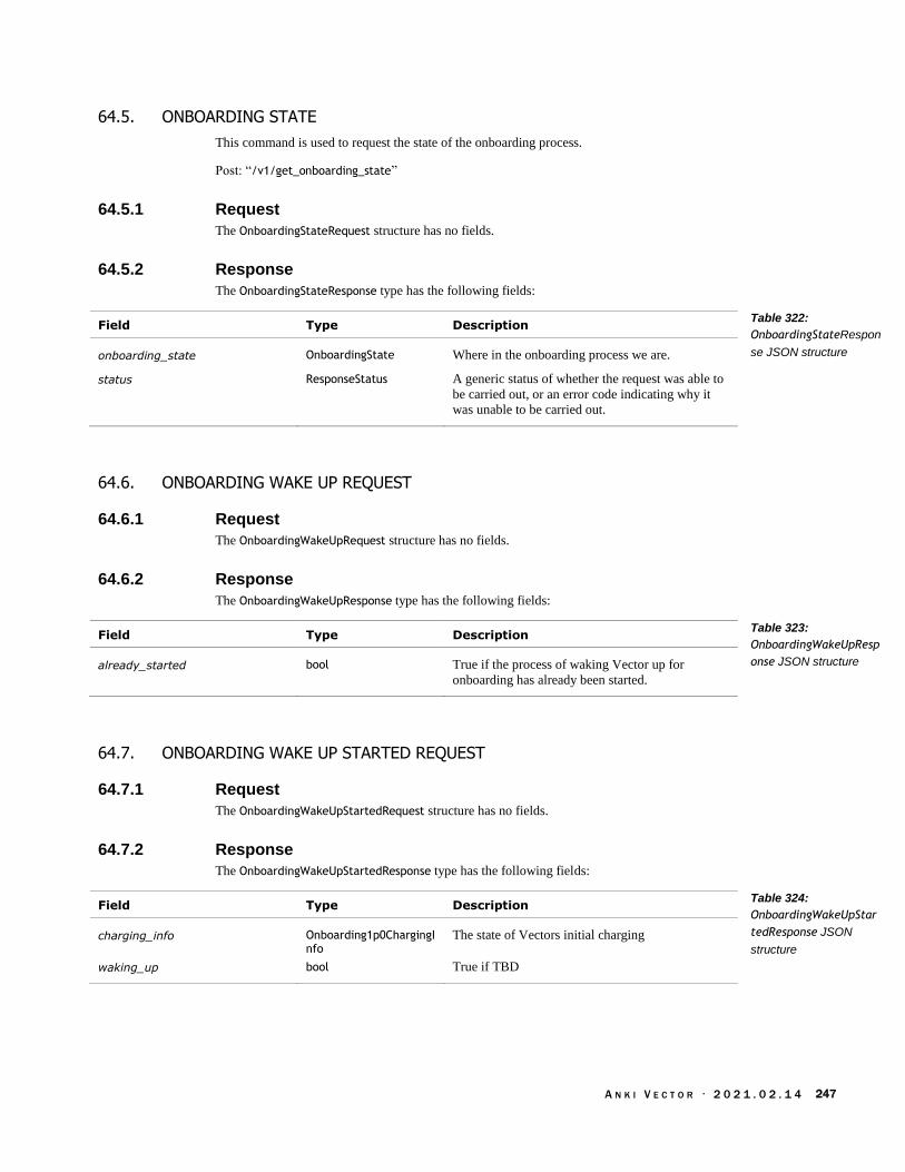
A N K I V E C T O R · 2 0 2 1 . 0 2 . 1 4 247
64.5. ONBOARDING STATE
This command is used to request the state of the onboarding process.
Post: “/v1/get_onboarding_state”
64.5.1 Request
The OnboardingStateRequest structure has no fields.
64.5.2 Response
The OnboardingStateResponse type has the following fields:
Field Type Description
onboarding_state OnboardingState Where in the onboarding process we are.
status ResponseStatus A generic status of whether the request was able to
be carried out, or an error code indicating why it
was unable to be carried out.
64.6. ONBOARDING WAKE UP REQUEST
64.6.1 Request
The OnboardingWakeUpRequest structure has no fields.
64.6.2 Response
The OnboardingWakeUpResponse type has the following fields:
Field Type Description
already_started bool True if the process of waking Vector up for
onboarding has already been started.
64.7. ONBOARDING WAKE UP STARTED REQUEST
64.7.1 Request
The OnboardingWakeUpStartedRequest structure has no fields.
64.7.2 Response
The OnboardingWakeUpStartedResponse type has the following fields:
Field Type Description
charging_info Onboarding1p0ChargingInfo
The state of Vectors initial charging
waking_up bool True if TBD
Table 322:
OnboardingStateRespon
se JSON structure
Table 323:
OnboardingWakeUpResp
onse JSON structure
Table 324:
OnboardingWakeUpStar
tedResponse JSON
structure

A N K I V E C T O R · 2 0 2 1 . 0 2 . 1 4 248
65. PHOTOS
This section describes the commands and queries related to accessing and managing photographs
(and their thumbnail images) on Vector. For a description of the photos, see Chapter 18 Image
Processing.
65.1. STRUCTURES
65.1.1 Photo Path
The PhotoPathMessage type has the following fields:
Field Type Description
full_path string
success bool True if the photograph exists; otherwise, the
photograph does not exist.
65.1.2 Thumbnail Path
The ThumbnailPathMessage type has the following fields:
Field Type Description
full_path string
success bool True if the thumbnail image exists; otherwise, the
thumbnail does not exist.
65.2. EVENTS
65.2.1 PhotoTaken
The PhotoTaken event is sent after Vector has taken a photograph and stored it. This structure has
the following fields:
Field Type Description
photo_id uint32 The identifier of the photograph taken.
Table 325:
PhotoPathMessage
JSON structure
Table 326:
ThumbnailPathMessage
JSON structure
Table 327: PhotoTaken
JSON structure

A N K I V E C T O R · 2 0 2 1 . 0 2 . 1 4 249
65.3. DELETE PHOTO
This command is used to delete a photograph and its thumbnail
Post: “/v1/delete_photo”
65.3.1 Request
The DeletePhotoRequest has the following fields:
Field Type Description
photo_id uint32 The identifier of the photograph to delete.
65.3.2 Response
The DeletePhotoResponse type has the following fields:
Field Type Description
status ResponseStatus A generic status of whether the request was able to
be carried out, or an error code indicating why it
was unable to be carried out.
success bool True if the photograph was successfully removed;
otherwise there was an error.
65.4. PHOTO
This command is used to retrieve the photograph’s image.
Post: “/v1/photo”
65.4.1 Request
The PhotoRequest structure has the following fields:
Field Type Description
photo_id uint32 The identifier of the photograph to request.
65.4.2 Response
The PhotoResponse type has the following fields:
Field Type Description
image bytes The data that make up the photograph’s image
status ResponseStatus A generic status of whether the request was able to
be carried out, or an error code indicating why it
was unable to be carried out.
success bool True if the photograph was successfully retrieved;
otherwise there was an error.
Table 328:
DeletePhotoRequest
JSON structure
Table 329:
DeletePhotoResponse
JSON structure
Table 330:
PhotoRequest JSON
structure
Table 331:
PhotoResponse JSON
structure

A N K I V E C T O R · 2 0 2 1 . 0 2 . 1 4 250
65.5. PHOTOS INFO
This command is used to get the list of photographs available on Vector.
Post: “/v1/photos_info”
65.5.1 Request
The PhotosInfoRequest structure has no fields.
65.5.2 Response
The PhotosInfoResponse type has the following fields:
Field Type Description
status ResponseStatus A generic status of whether the request was able to
be carried out, or an error code indicating why it
was unable to be carried out.
photo_infos PhotoInfo[] An array of information about the photographs
available on Vector.
The PhotoInfo type has the following fields:
Field Type Description
photo_copied_to_app bool True if the photograph has been downloaded to the
application.
photo_id uint32 The identifier of this photograph. This can be used
to retrieve the thumbnail, photograph or to delete it.
thumb_copied_to_app bool True if the thumbnail image has been downloaded
to the application.
timestamp_utc uint32 The time that the photograph was taken. The
format is unix time: seconds since 1970, in UTC.
Table 332:
PhotosInfoResponse
JSON structure
Table 333: PhotoInfo
JSON structure
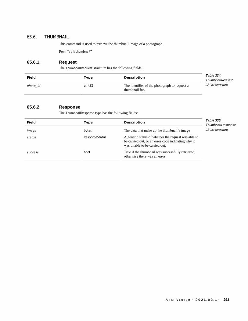
A N K I V E C T O R · 2 0 2 1 . 0 2 . 1 4 251
65.6. THUMBNAIL
This command is used to retrieve the thumbnail image of a photograph.
Post: “/v1/thumbnail”
65.6.1 Request
The ThumbnailRequest structure has the following fields:
Field Type Description
photo_id uint32 The identifier of the photograph to request a
thumbnail for.
65.6.2 Response
The ThumbnailResponse type has the following fields:
Field Type Description
image bytes The data that make up the thumbnail’s image
status ResponseStatus A generic status of whether the request was able to
be carried out, or an error code indicating why it
was unable to be carried out.
success bool True if the thumbnail was successfully retrieved;
otherwise there was an error.
Table 334:
ThumbnailRequest
JSON structure
Table 335:
ThumbnailResponse
JSON structure
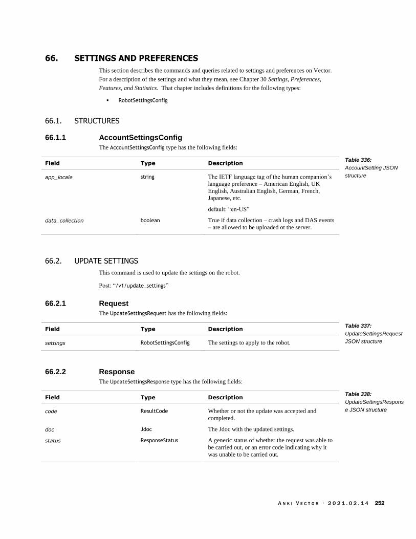
A N K I V E C T O R · 2 0 2 1 . 0 2 . 1 4 252
66. SETTINGS AND PREFERENCES
This section describes the commands and queries related to settings and preferences on Vector.
For a description of the settings and what they mean, see Chapter 30 Settings, Preferences,
Features, and Statistics. That chapter includes definitions for the following types:
RobotSettingsConfig
66.1. STRUCTURES
66.1.1 AccountSettingsConfig
The AccountSettingsConfig type has the following fields:
Field Type Description
app_locale string The IETF language tag of the human companion’s
language preference – American English, UK
English, Australian English, German, French,
Japanese, etc.
default: “en-US”
data_collection boolean True if data collection – crash logs and DAS events
– are allowed to be uploaded ot the server.
66.2. UPDATE SETTINGS
This command is used to update the settings on the robot.
Post: “/v1/update_settings”
66.2.1 Request
The UpdateSettingsRequest has the following fields:
Field Type Description
settings RobotSettingsConfig The settings to apply to the robot.
66.2.2 Response
The UpdateSettingsResponse type has the following fields:
Field Type Description
code ResultCode Whether or not the update was accepted and
completed.
doc Jdoc The Jdoc with the updated settings.
status ResponseStatus A generic status of whether the request was able to
be carried out, or an error code indicating why it
was unable to be carried out.
Table 336:
AccountSetting JSON
structure
Table 337:
UpdateSettingsRequest
JSON structure
Table 338:
UpdateSettingsRespons
e JSON structure

A N K I V E C T O R · 2 0 2 1 . 0 2 . 1 4 253
66.3. UPDATE ACCOUNT SETTINGS
This command is used to update the account wide settings, such as opning into or out of data
collection.
Post: “/v1/update_account_settings”
66.3.1 Request
The UpdateAccountsSettingsRequest has the following fields:
Field Type Description
account_settings AccountSettingsConfig The new account settings.
66.3.2 Response
The UpdateAccountsSettingsResponse type has the following fields:
Field Type Description
code ResultCode Whether or not the update was accepted and
completed.
doc Jdoc The Jdoc with the updated settings.
status ResponseStatus A generic status of whether the request was able to
be carried out, or an error code indicating why it
was unable to be carried out.
Table 339: JSON
Parameters for
UpdateAccountSettings
Request
Table 340:
UpdateAccountSettings
Response JSON
structure

A N K I V E C T O R · 2 0 2 1 . 0 2 . 1 4 254
67. SOFTWARE UPDATES
These commands are siblings to the OTA Update and related commands in Chapter 13 Bluetooth
LE protocol. However, they differ: in some cases, less information, in others they present the same
information in different ways.
67.1. ENUMERATIONS
67.1.1 UpdateStatus
The UpdateStatus enumeration has the following named values:
Name Value Description
IN_PROGRESS_DOWNLOAD 2 The software update is currently being downloaded.
NO_UPDATE 0 There are no software updates available.
READY_TO_INSTALL 1 The software update has been downloaded and is
ready to install.
67.2. START UPDATE ENGINE
“StartUpdateEngine cycles the update-engine service (to start a new check for an update) and sets
up a stream of UpdateStatusResponse events.”
Post: “/v1/start_update_engine”
This command uses the same request and response structures as CheckUpdateStatus
67.3. CHECK UPDATE STATUS
“CheckUpdateStatus tells if the robot is ready to reboot and update.”
Post: “/v1/check_update_status”
67.3.1 Request
The CheckUpdateStatusRequest structure has no fields.
67.3.2 Response
This is streamed set of update status. The CheckUpdateStatusResponse type has the following
fields:
Field Type Description
expected int64 The number of bytes expected to be downloaded
progress int64 The number of bytes downloaded
status ResponseStatus A generic status of whether the request was able to
be carried out, or an error code indicating why it
was unable to be carried out.
update_status UpdateStatus Whether the update engine is active, and where in
the update process it is.
update_version string The version of software being updated to.
Table 341:
UpdateStatus
Enumeration
Table 342:
CheckUpdateStatusRes
ponse JSON structure

A N K I V E C T O R · 2 0 2 1 . 0 2 . 1 4 255
67.4. UPDATE AND RESTART
Post: “/v1/update_and_restart”
67.4.1 Request
The UpdateAndRestartRequest structure has no fields.
67.4.2 Response
The UpdateAndRestartResponse has the following fields:
Field Type Description
status ResponseStatus A generic status of whether the request was able to
be carried out, or an error code indicating why it
was unable to be carried out.
68. HISTORICAL ODDITIES
The Github repository is interesting for the SDK commands that were removed. The last version
of the repository for many of these commands is:
https://github.com/anki/vector-python-sdk/tree/c14082af5a947c23016111c1f73a445d8356dbf8
Some commands removed from this repository (possibly later) because they were not implemented
on Vector include:
Network statistics
Ability to set and fetch the camera settings
Motion observed events
An audio stream from Vector’s microphone to the SDK application
Table 343:
UpdateAndRestartResp
onse JSON structure
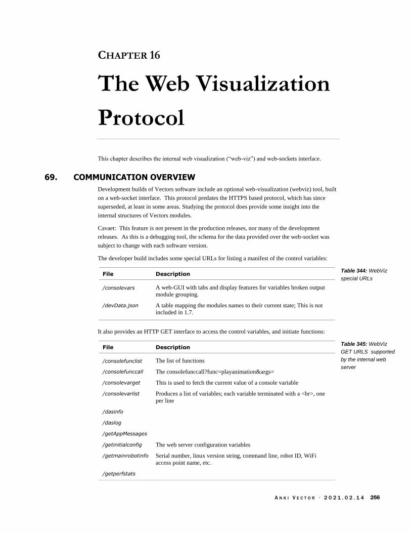
A N K I V E C T O R · 2 0 2 1 . 0 2 . 1 4 256
CHAPTER 16
The Web Visualization
Protocol
This chapter describes the internal web visualization (“web-viz”) and web-sockets interface.
69. COMMUNICATION OVERVIEW
Development builds of Vectors software include an optional web-visualization (webviz) tool, built
on a web-socket interface. This protocol predates the HTTPS based protocol, which has since
superseded, at least in some areas. Studying the protocol does provide some insight into the
internal structures of Vectors modules.
Cavaet: This feature is not present in the production releases, nor many of the development
releases. As this is a debugging tool, the schema for the data provided over the web-socket was
subject to change with each software version.
The developer build includes some special URLs for listing a manifest of the control variables:
File Description
/consolevars A web-GUI with tabs and display features for variables broken output
module grouping.
/devData.json A table mapping the modules names to their current state; This is not
included in 1.7.
It also provides an HTTP GET interface to access the control variables, and initiate functions:
File Description
/consolefunclist The list of functions
/consolefunccall The consolefunccall?func=playanimation&args=
/consolevarget This is used to fetch the current value of a console variable
/consolevarlist Produces a list of variables; each variable terminated with a <br>, one
per line
/dasinfo
/daslog
/getAppMessages
/getinitialconfig The web server configuration variables
/getmainrobotinfo Serial number, linux version string, command line, robot ID, WiFi
access point name, etc.
/getperfstats
Table 344: WebViz
special URLs
Table 345: WebViz
GET URLS supported
by the internal web
server

A N K I V E C T O R · 2 0 2 1 . 0 2 . 1 4 257
/getprocessstatus
/processstatus
/sendAppMessage
/systemctl
69.1. CONSOLE VARIABLES
The control variables are the module settings, and internal measurements. All variable names are
lexical numbers, digits, and underscore – no spaces, no periods, etc. The list of console variables
can be found in a few different ways:
/consolevars is not convenient, and would required a lot of scrapping
/consolevarlist
/consolefunccall?func=List_Variables will provide the list of variables, their associated
module, and their current value
note: the module name can have spaces; it can also be dotted, as in Major and Minor name.
69.1.1 Getting A Console Variable’s Current Value
The value associated with a console variable can be fetched with an HTTP GET:
/consolevarget?key=name_of_variable
69.1.2 Setting A Console Variable to a Value
A console variable can be set with an HTTP GET:
/consolevarset?key=name_of_variable&value=new_value
70. WEBSOCKET OVERVIEW
From the application level the protocol is organized into as stream of module-specific JSON
messages that share a common web-socket, plus some management of that stream:
Subscribe, and unsubscribe to module-specific events
Receiving module-specific messages from the robot
Sending module-specific message to the robot

A N K I V E C T O R · 2 0 2 1 . 0 2 . 1 4 258
WebSocket
Fra
me · Type
· Module
· Data
Module specific
JSON
Module specific
JSON
Module specific
JSON
Before we go further we’ll need to know the module identifiers. The modules differ by ports that
vend their events:
Module Name Port(s) Description
Alexa 8889 Alexa related events
AnimationEngine 8888 Animation trigger events
Animations 8889 Events related to the start and completion of
animations.
AudioEvents 8889 The starting and stopping audio
BeatDetector 8888 Events related to listening for music and its beat
Behaviors 8888 Events related to the current behavior tree
BehaviorConds 8888 Events related to the current behavior tree, and
conditions
CloudIntents 8888 Events related to connecting to the cloud voice
server
Cpu 8888
CpuProfile 8888 8889
Cubes 8888 Provides events related to the cube communication
link and interaction.
Features 8888 Provides which feature toggles are enabled and
disabled.
Habitat 8888 Events related to detecting the habitat (sold as
“Vector Space”)
HeldInPalm 8888 Events related to being held in palm; appears to be
unimplemented.
IMU 8888
Intents 8888 Events related to processing intents
MicData 8889
Mood 8888 Events related to Vector’s current emotional state (or
mood).
NavMap 8888
ObservedObjects 8888 Event related to observed faces, cubes, and other
Figure 63: Overview of
the websocket wrapper
Table 346: Module
names and their ports

A N K I V E C T O R · 2 0 2 1 . 0 2 . 1 4 259
marked objects.
Power 8888 Changes in who is requesting Vector to enter a
power save state.
Sleeping 8888 Events related to Vector’s sleep behavior
SoundReactions 8888
SpeechRecognizerSys 8889
Touch 8888 Events related to the touch sensor
VisionScheduleMediator 8888 Events related to the management of the image
processing system.
70.1. SETTING UP THE COMMUNICATION CHANNEL
The URL to connect to is:
ws://address:port/socket
Where the address is the address of the Vector of interest, and the port is the shared port for the
modules of interest, given in the earlier table.
To subscribe to events from a module post the following JSON structure to the web socket:
Field Type Description
module string The lower case name of the module to subscribe to events
from. See Table 346: Module names and their ports for the
module names
type string “subscribe”
To unsubscribe from events from a module post the following JSON structure to the web socket:
Field Type Description
module string The lower case name of the module to unsubscribe to events
from. See Table 346: Module names and their ports for the
module names
type string “unsubscribe”
Events related to the module will come with the following structure:
Field Type Description
data JSON The event structure for the given module.
module string The name of the module to unsubscribe to events from. See
Table 346: Module names and their ports for the module
names. The module name is not guaranteed to be in lower
case; any matching should be performed in a case-less
fashion.
Table 347: Subscribing
to a module’s events
Table 348:
Unsubscribing from a
module’s events
Table 349: Module
event parameters
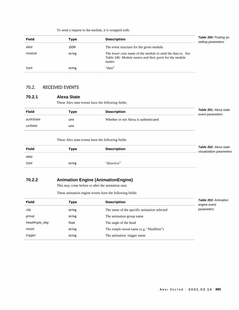
A N K I V E C T O R · 2 0 2 1 . 0 2 . 1 4 260
To send a request to the module, it is wrapped with:
Field Type Description
data JSON The event structure for the given module.
module string The lower case name of the module to send the data to. See
Table 346: Module names and their ports for the module
names
type string “data”
70.2. RECEIVED EVENTS
70.2.1 Alexa State
These Alex state events have the following fields:
Field Type Description
authState uint Whether or not Alexa is authenticated
uxState uint
These Alex state events have the following fields:
Field Type Description
data
type string “directive”
70.2.2 Animation Engine (AnimationEngine)
This may come before or after the animation start.
These animation engine events have the following fields:
Field Type Description
clip string The name of the specific animation selected
group string The animation group name
headAngle_deg float The angle of the head
mood string The simple mood name (e.g. “MedStim”)
trigger string The animation trigger name
Table 350: Posting an
setting parameters
Table 351: Alexa state
event parameters
Table 352: Alexa state
visualization parameters
Table 353: Animation
engine event
parameters

A N K I V E C T O R · 2 0 2 1 . 0 2 . 1 4 261
70.2.3 Animations
This animation state event includes a type field that describes how to interpret the rest of the
structure. The events have the following fields:
Field Type Description
animation string The name of the animation
type string “start” if the animation is starting.
“stop” if the animation has completed.
70.2.4 Audio events
See Chapter 25 for details of the audio events. The event includes a type field that describes how
to interpret the rest of the structure.
When an audio event is sent, the event structure has the following fields:
Field Type Description
eventName string The name of the event (or its identifier) that was sent to the
audio engine.
gameObjectId string The identifier that the audio engine will use for the object;
this identifier is expected to link to items within Vector’s
“game world” – his mental model.
hasCallback boolean
time float The time that this occurred at (seconds since power on)
type string “PostAudioEvent”
When all audio events are stopped, the event structure has the following fields:
Field Type Description
eventName string The name of the event (or its identifier) that was sent to the
audio engine.
gameObjectId string The identifier that the audio engine will use for the object;
this identifier is expected to link to items within Vector’s
“game world” – his mental model.
time uint The time that this occurred at (seconds since power on)
type string “StopAllAudioEvents”
When an audio group is set to a new state, an event structure with the following fields is sent:
Field Type Description
stateGroupId string The state group to modify
stateId The new state that the group is being put into
time uint The time that this occurred at (seconds since power on)
type string “SetState”
Table 354: Animation
state event parameters
Table 355: Audio post
event parameters
Table 356: Audio stop
all event parameters
Table 357: Audio state
group event parameters

A N K I V E C T O R · 2 0 2 1 . 0 2 . 1 4 262
When an audio switch group is set to a new state, the event structure has the following fields:
Field Type Description
gameObjectId string The new state that the switch is being changed into.
switchGroupId string The switch being modified.
switchStateId The new state that the switch is being put into
time float The time that this occurred at (seconds since power on)
type string “SetSwitchState”
70.2.5 Beat Detector (BeatDetector)
See Chapter 18 section 76.5 Beat Detection for the event structures.
70.2.6 Behaviors
Todo There are two forms of events send by the behaviors module.
Can also be an array of strings. Which lists every behavior name.
When a behavior event is sent, the event structure has the following fields:
Field Type Description
activeFeature string The name of the active AI feature (given as associated
ActiveFeature in the behavior node, appendix I) followed by
space and “(AI)”. Optional
debugState string example: driving. Optional
stack string[] An array of behavior identifiers. The last item is the current
active behavior. Optional
time float The time that this occurred at (seconds since power on).
Optional
tree TreeNode[] The behavior’s and their parents. Optional
The behavior TreeNode structure has the following fields:
Field Type Description
behaviorID string The identifier for a given behavior node
parent string The identifier of the parent node for this behavior. Some are
prefixed by an @ symbol
70.2.7 Behavior Conditions (BehaviorConds)
Note: “when the stack changes, we'll receive new conditions before receiving the stack.”
When a behavior condition event is sent, the event structure has the following fields:
Field Type Description
factors Factor[] The current set of factors being examined. Optional
inactive string The name of condition that is now inactive. Optional
Table 358: Audio switch
group event parameters
Table 359: Behavior
event parameters
Table 360: TreeNode
parameters
Table 361: Behavior
condition events
parameters

A N K I V E C T O R · 2 0 2 1 . 0 2 . 1 4 263
owner string The name of the owning behavior. Optional. Note: if factors
is present, this is not.
stack string[] An array of behavior identifiers. The last item is the current
active behavior. Optional
time float The time that this occurred at (seconds since power on)
tree TreeNode[] The behaviors and their parents. Optional
The Factor structure has the following fields:
Field Type Description
areConditionsMet boolean True of the conditions for the behavior were met: they have
all been true
conditionLabel string The name of the condition
ownerDebugLabel string The name of the owning behavior.
70.2.8 Cloud Intent
The cloud intent event is a structure or an array of structures with the following fields:
Field Type Description
file string Path, internal to the system, to the capture
debug file. Remove the leading
“/data/data/com.anki.victor” to get the URL resource path.
Only present if type is “debugFile”. Optional
time int The time in UTC seconds
type string “debugFile” or …
The cloud intent event is a structure or an array of structures with the following fields:
Field Type Description
error string “Token” if there hasn’t been a token passed to vector {Also
write up why this is important.}
time int The time in UTC seconds
type string “error”
70.2.9 CPU
When a CPU event is sent, the event structure has the following fields:
Field Type Description
deltaTime_ms int The time step in milliseconds
usage string[] An array of processor usage stats from procstat35, one for
each processor
35 http://www.linuxhowtos.org/System/procstat.htm
Table 362: Factor
parameters
Table 363: Cloud event
parameters
Table 364: Cloud event
parameters
Table 365: CPU
parameters

A N K I V E C T O R · 2 0 2 1 . 0 2 . 1 4 264
70.2.10 CPU Profile
When a CPU profile event is sent, the event structure has the following fields:
Field Type Description
sample Sample[] An array of CPU usage samples for the thread
threadName string The name of the thread that was measured for this CPU
profile
time float Time stamp
The Sample structure has the following fields:
Field Type Description
max float The maximum CPU usage during the time interval
mean float The average CPU usage during the time interval
min float The minimum CPU usage during the time interval
name string The name of the thread that this belongs to
70.2.11 Cubes
Note: The Cube events are sent regardless of whether Vector is communication with his cube.
When a Cube event is sent, the event structure has the following fields:
Field Type Description
cccInfo CCCInfo Optional
citInfo CitInfo Optional
commInfo CommInfo Information about the connected cube, and the state of the
connection. Optional
Table 366: CPU profile
parameters
Table 367: Sample
parameters
Table 368: Cube event
parameters

A N K I V E C T O R · 2 0 2 1 . 0 2 . 1 4 265
The CCCInfo structure has the following fields:
Field Type Description
connectionState string The state of the connection. “Unconnected” or
“UnConnected”36, “Connecting”., “ConnectedBackground”,
or “Interactable” or.. “ConnectedInteractable”
“ConnectedSwitchingToBackground”
stateCountdown StateCountDown[] The time left before the temporary connection expires
subscriberData SubscriberData[] Information about which modules have requested which
level of connection with the cube.
The CitInfo structure has the following fields:
Field Type Description
heldProbability The probability that the cube is being held.
movedFarRecently boolean “Recently Moved Far, assuming is held”
movedRecently boolean True if the cube has recently moved; false otherwise.
NoTarget boolean True if the cube is not visible; false otherwise. Optional
targetInfo TargetInfo This is included if the cube is observed. Optional
timeSinceHeld float The number of seconds since the cube was last held
timeSinceMoved float The number of seconds since the cube was last moved
timeSinceObserved float The number of seconds since the cube was last observed
timeSinceTapped float The number of seconds since the cube was last tapped
trackingState string Tracking State (“Idle” “TrackingConnected)
userHoldingCube boolean True if someone holding the cube; false otherwise.
visibleRecently boolean True if the cube is visually seen; false otherwise.
visTrackingRate string VSM Tracking Rate Request: “High” or “Low”
The CommInfo structure has the following fields:
Field Type Description
connectedCube string The identifier for the cube that Vector is connected with.
“(none)” if not connected with a cube.
connectionState string The state of the connection: “UnconnectedIdle”,
“PendingConnect”, “Connected”, “ScanningForCubes”,
“PendingDisconnect”
cubeData CubeData[] The cubes that Vector has received Bluetooth LE
advertisements from.
preferredCube string The identifier for the cube that Vector would prefer to
connect with, if available.
36 What does this mean if there are both?
Table 369: CCCInfo
parameters
Table 370: CitInfo
parameters
Table 371: CommInfo
parameters

A N K I V E C T O R · 2 0 2 1 . 0 2 . 1 4 266
Note: this implies that Vector will try first to connect with his preferred cube, and, if necessary, fall
back to the next first cube he can find.
The CubeData structure has the following fields:
Field Type Description
address string The MAC address of the cube
lastRssi int The last received “received signal strength indicator” (RSSI)
measurement from the cube.
The StateCountDown structure has the following fields:
Field Type Description
DisconnectingIn The duration before the connection will exit
SwitchingToBackgroundIn string
The SubscriberData structure has the following fields:
Field Type Description
ExpiresIn The duration before the connection will exit. This field is
only present if the subscriber has included a timeout.
Optional
SubscriberName string The name of the behavior (the ID) that requested this
connection.
SubscriptionType string “Background” or “Interactable”
The TargetInfo structure has the following fields:
Field Type Units Description
angle float degrees Relative angle to the cube face
distance float mm The distance to the cube (or cube center?)
distMeasuredByProx boolean True if the distance to the cube as measured by the time of
flight sensor.
70.2.12 Features
The features event is an array of structures with the following fields:
Field Type Units Description
default string “none”, “enabled”,
“disabled”
Whether or not the feature is enabled or disabled by default.
name string The name of the AI feature
override string “none”, “enabled”, “disabled”
Whether or not the feature is enabled or disabled
Table 372: CubeData
parameters
Table 373:
StateCountDown
parameters
Table 374:
SubscriberData
parameters
Table 375: TargetInfo
parameters
Table 376: Feature
event parameters

A N K I V E C T O R · 2 0 2 1 . 0 2 . 1 4 267
70.2.13 Habitat
The habitat event is sent to convey information about being in, and driving around in the habitat
tray. See Chapter 5 for a brief description of the habitat. The event is a structure with the
following fields:
Field Type Units Description
habitatState string HabitatState Whether or not Vector has detected his habitat (tray). See
habit state enumeration for possible values.
reason string “CliffDetected”
stopOnWhiteEnabled string “yes”, “no”
whiteThresholds string Example: “[400,400] 0 readings so far"”
The HabitatState enumeration has the following possible values:
State Description
InHabitat Vector is in the habitat area.
NotInHabitat Vector is not in the habitat.
Unknown Vector does not (yet) know if he is in the habitat.
70.2.14 Held In Palm
Not implemented?
70.2.15 IMU State
When an IMU state event is sent, the event structure has the following fields:
Field Type Description
fall_impact_count uint Fall impact count
70.2.16 Intents
The intents events can come in two different forms. In one kind, as an array of the following
structure:
Field Type Description
intentType string “user” or “cloud”
list string[] A list of the intent names available for this type of intent.
type string “all-intents”
In the other as a structure for a single intent in response to a user interaction:
Field Type Description
intentType string “user”
type string “current-intents”
Table 377: Habitat
event parameters
Table 378: Habitat
state enumeration
Table 379: IMU state
event parameters
Table 380: Intents
structure parameters
Table 381: Intents
structure parameters

A N K I V E C T O R · 2 0 2 1 . 0 2 . 1 4 268
value string The intent from the cloud
70.2.17 Microphone data (MicData)
See also section 76.5 Beat Detection.
The microphone data event is a structure with the following fields:
Field Type Units Description
activeState boolean True if a voice has been detected.
beatDetector BeatDetector Information about the beat(s) heard
delayTime float ms
direction uint The direction to the origin of the strongest sound.
directions uint[] The confidence in each of the directions
latestNoiseFloor float A measure of the ambient noise level.
latestPowerValue float A measure of the most recent sound loudness
maxConfidence int The maximum confidence value in the directions array
selectedDirection uint The direction that is picked for the origin of the sound of
interest.
time float seconds The time that this occurred at (seconds since power on)
triggerDetected boolean True if the trigger word has been detected
The BeatDetector structure has the following fields:
Field Type Units Description
confidence float How confident the analysis is in the tempo measurement.
tempo_bpm float beats / minute
The measured number of beats per minute.
70.2.18 Mood
These structures are similar to, but differ from, those in Chapter 29.
When mood event is sent, the event structure has the following fields:
Field Type Units Description
emotionEvent string The name of the event (see appendix K Table 641: The emotion
event names). Optional
info Info[] This is sent when the event is first subscribed to. Optional.
moods Mood[] An array emotion event structures (see below).
simpleMood string One of the simple mood names. Optional
time float seconds The time that this occurred at (seconds since power on)
Table 382: Microphone
data event parameters
Table 383: BeatDetecto
parameters
Table 384: Mood event
parameters
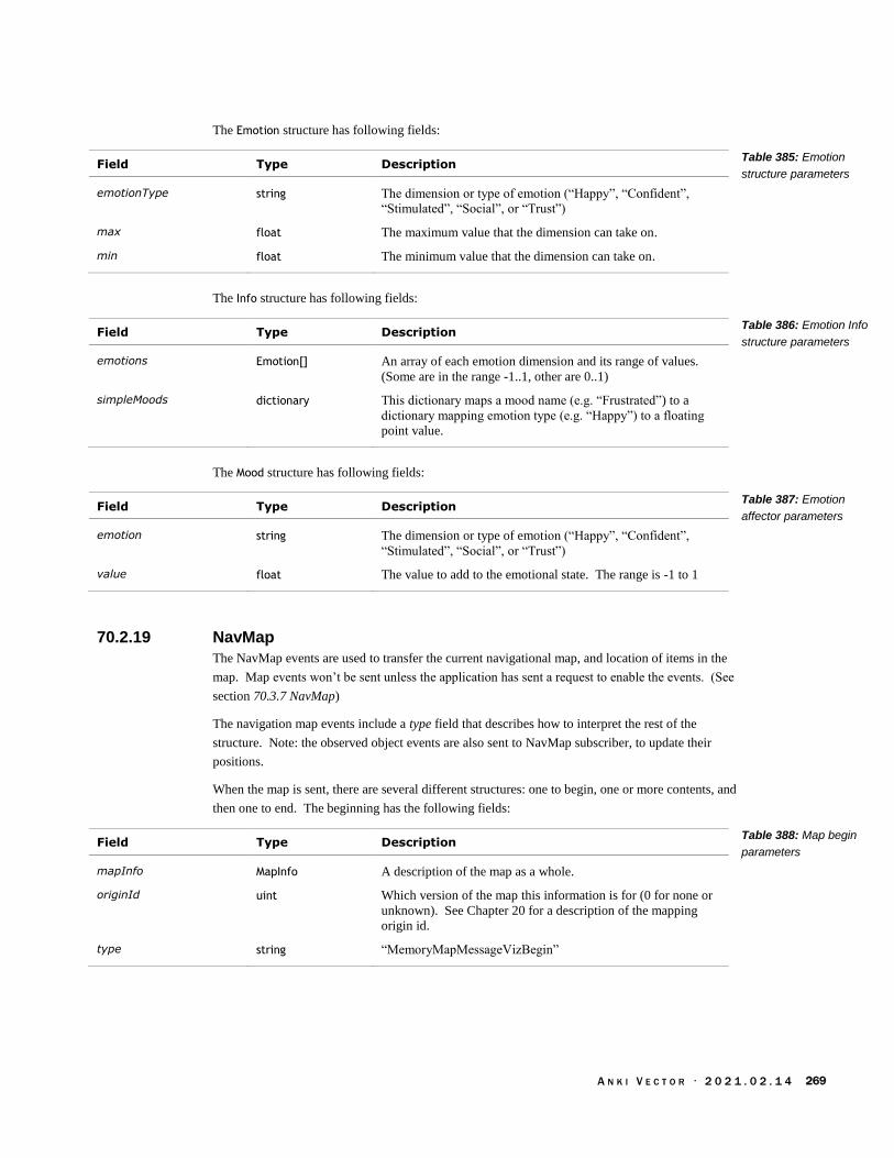
A N K I V E C T O R · 2 0 2 1 . 0 2 . 1 4 269
The Emotion structure has following fields:
Field Type Description
emotionType string The dimension or type of emotion (“Happy”, “Confident”,
“Stimulated”, “Social”, or “Trust”)
max float The maximum value that the dimension can take on.
min float The minimum value that the dimension can take on.
The Info structure has following fields:
Field Type Description
emotions Emotion[] An array of each emotion dimension and its range of values.
(Some are in the range -1..1, other are 0..1)
simpleMoods dictionary This dictionary maps a mood name (e.g. “Frustrated”) to a
dictionary mapping emotion type (e.g. “Happy”) to a floating
point value.
The Mood structure has following fields:
Field Type Description
emotion string The dimension or type of emotion (“Happy”, “Confident”,
“Stimulated”, “Social”, or “Trust”)
value float The value to add to the emotional state. The range is -1 to 1
70.2.19 NavMap
The NavMap events are used to transfer the current navigational map, and location of items in the
map. Map events won’t be sent unless the application has sent a request to enable the events. (See
section 70.3.7 NavMap)
The navigation map events include a type field that describes how to interpret the rest of the
structure. Note: the observed object events are also sent to NavMap subscriber, to update their
positions.
When the map is sent, there are several different structures: one to begin, one or more contents, and
then one to end. The beginning has the following fields:
Field Type Description
mapInfo MapInfo A description of the map as a whole.
originId uint Which version of the map this information is for (0 for none or
unknown). See Chapter 20 for a description of the mapping
origin id.
type string “MemoryMapMessageVizBegin”
Table 385: Emotion
structure parameters
Table 386: Emotion Info
structure parameters
Table 387: Emotion
affector parameters
Table 388: Map begin
parameters

A N K I V E C T O R · 2 0 2 1 . 0 2 . 1 4 270
The MapInfo is used to describe the map as a whole. It has the following fields:
Field Type Units Description
identifier string Unique name of the map version
rootCenterX float mm The X coordinate of the maps center
rootCenterY float mm The y coordinate of the maps center
rootCenterZ float mm The z coordinate of the maps center
rootDepth int The depth of the quad tree: the number levels to the leaf nodes.
rootSize_mm float mm The length and width of the whole map. (The map is square).
This is followed by a stream of the following structure:
Field Type Description
originId uint The generation/version of the map this information is for (0 for
none or unknown). See Chapter 20 for a description of the
mapping origin id.
seqNum uint Each part of the map transfer has a different sequence number.
quadInfos QuadInfo[] The individual elements of the map.
type string “MemoryMapMessageViz”
The QuadInfo is “an individual sample of Vector's [navigation] map. This quad's size will vary and
depends on the resolution the map requires to effectively identify boundaries in the environment.”
It has the following fields:
Field Type Description
colorRGBA uint32 Suggested color for the area of the map, used when visualizing
the map.
content string A tag of what Vector has identified as located in this area.
“Unknown”, “ClearOfObstacle” , “ClearOfCliff”,
“ObstacleCube”, “ObstacleCharger”, “ObstacleProx”,
“ObstacleProxExplored”, “ObstacleUnrecognized”, “Cliff”,
“InterestingEdge”, “NotInterestingEdge”
depth uint32 The depth within the tree.
The end of the map transfer the following fields:
Field Type Description
originId uint The generation/version of the map this information is for (0 for
none or unknown). See Chapter 20 for a description of the
mapping origin id.
robot Pose The robot’s position and orientation within the map.
type string “MemoryMapMessageVizEnd”
Table 389: MapInfo
structure
Table 390: Map
message parameters
Table 391: QuadInfo
structure
Table 392: Map end
parameters

A N K I V E C T O R · 2 0 2 1 . 0 2 . 1 4 271
The Pose structure has the following fields:
Field Type Units Description
qW float Part of the rotation quaternion
qX float Part of the rotation quaternion
qY float Part of the rotation quaternion
qZ float Part of the rotation quaternion
x float The x coordinate
y float The y coordinate
z float The z coordinate
The cube location is updated with an event with the following fields:
Field Type Description
cubes Cube[] A list of the cube’s location and orientatios
type string “MemoryMapCubes”
The Cube structure has the following fields:
Field Type Units Description
angle float degrees Relative angle to the cube face
x float mm The x coordinate
y float mm The y coordinate
z float mm The z coordinate
A face location is updated with an event with the following fields:
Field Type Description
faceID int The identifier for the face that was observed
pose Pose The face position and orientation
type string “MemoryMapFace”
70.2.20 Observed Objects
The observed object event includes a type field that describes how to interpret the rest of the
structure.
The deleted face event is sent when Vector no longer sees a given face. The structure has the
following fields:
Field Type Description
faceID int The identifier for the face that was removed.
type string “RobotDeletedFace”
Table 393: Pose
parameters
Table 394: Map cube
location parameters
Table 395: Cube
parameters
Table 396: Map face
location parameters
Table 397: Deleted face
event parameters

A N K I V E C T O R · 2 0 2 1 . 0 2 . 1 4 272
The deleted object event is sent when Vector no longer sees a given object. The structure has the
following fields:
Field Type Description
objectID int The identifier for the object that was removed.
type string “RobotDeletedLocatedObject”
This observed face event is sent while Vector sees and tracks a face in his view. The structure has
the following fields:
Field Type Description
faceID int The identifier for the face that was observed
name string Optional
originID uint Which version of the map this pose is in (0 for none or
unknown). See Chapter 20 for a description of the mapping
origin id.
timestamp uint The event time stamp (milliseconds since power on)
type string “RobotObservedFace”
This observed object event is sent while Vector sees and tracks a face in his view. The structure
has the following fields:
Field Type Description
isActive int 1, 0
objectID int The identifier for the face that was observed
objectType string “UnknownObject”, “Block_LIGHTCUBE1”,
“Block_LIGHTCUBE2”, “Block_LIGHTCUBE3”,
“Block_LIGHTCUBE_GHOST”, “Charger_Basic”,
“CustomType00”, “CustomType01”, “CustomType02”,
“CustomType03”, “CustomType04”, “CustomType05”,
“CustomType06”,”CustomType07”, “CustomType08”,
“CustomType09”, “CustomType10”, “CustomType11”,
“CustomType12”, “CustomType13”, “CustomType14”,
“CustomType15”, “CustomType16”, “CustomType17”,
“CustomType18”,”CustomType19”, “CustomFixedObstacle”
timestamp uint The event time stamp (milliseconds since power on)
type string “RobotObservedObject”
Note the code has object observed events sent on two websockets!
70.2.21 Power
The power event is a structure with the following fields (or an array of these structures):
Field Type Description
powerSaveEnabled boolean True if in power saving mode, false otherwise
powerSaveRequesters JSON string A string. The square bracketed and internally has a comma
delimited list of the names of the modules requesting that the
system go into low power state. The names are not quoted. An
Table 398: Deleted
located object event
parameters
Table 399: Observed
face event parameters
Table 400: Observed
object event parameters
Table 401: Power event
parameters

A N K I V E C T O R · 2 0 2 1 . 0 2 . 1 4 273
empty list is [].
70.2.22 Sleeping
The sleeping event is structure with the following fields:
Field Type Units Description
last_sleep_reason string Example: “Emergency”, “Sleepy” Optional
last_wake_reason string Possibly: Jolted, NotInAir, PickedUp, Poked, Sound,
LightsOn
“NotSleepy”, “Poked” Optional
reaction_state string Example: “NotReacting”, “TriggerWord” Optional
sleep_cycle string “Awake”, “CheckingForPerson”, “Comatose”, “DeepSleep”,
“EmergencySleep” , “GoingToCharger”,
“HeldInPalmSleep”, “LightSleep”, “Nothing”,
“PreSleepAnimation”, “SleepOnCharger”, “SleepOnPalm”
Optional
sleep_debt_hours float hours This goes up the longer he is active, and down as he sleeps.
Optional
See Chapter 8 for a brief description of the sleep debt.
70.2.23 SoundReactions
See also section 70.2.23 SoundReactions
The sound reaction event is a structure with the following fields:
Field Type Units Description
activeState boolean True if a voice has been detected. False otherwise.
confidence int The confidence in the direction.
direction uint The index of the direction to the origin of the strongest
sound.
isTriggered boolean True if sound activity (above the noise level) has been heard
latestNoiseFloor float A measure of the ambient noise level.
latestPowerValue float A measure of the most recent sound loudness
powerScore float A measure of how loud it is at this instance.
powerScoreAvg float A measure of loud it has been over the past few seconds.
powerScoreThreshold float This is greater than or equal to the powerScoreMinThreshold.
Note: this value can be less than the latestNoiseFloor.
powerScoreMinThreshold float
selectedDirection uint The direction that is picked for the origin of the sound of
interest.
time float seconds The time that this occurred at (seconds since power on)
triggerDirection uint The index of the direction register when the sound
activitywas most recently heard.
triggerConfidence int The confidence in the trigger direction.
Table 402: Sleeping
event parameters
Table 403:
SoundReactions event
parameters

A N K I V E C T O R · 2 0 2 1 . 0 2 . 1 4 274
triggerScore float A score given to how likely the trigger was correctly
detected.
70.2.24 Speech Recognizer
The speech recognizer event is structure with the following fields (or an array of these structures):
Field Type Units Description
endSampleIndex uint index
endTime_ms uint ms
result string The text said, e.g. “hey vector”
notch boolean
playback boolean
score uint A score given to how likely the trigger was correctly
detected.
startSampleIndex uint index
startTime_ms uint ms
70.2.25 Touch Sensor
The touch sensor event message has the following fields:
Field Type Description
calibrated string “yes” or “no”
count uint
enabled string “true” “false”
esn string The robot’s electronic serial number.
osVersion string The version of the software running on Vector.
70.2.26 Vision Schedule Mediator
The vision schedule event message has the following fields:
Field Type Units Description
fullSchedule Schedule[] When the modes run and such
numActiveModes uint count The number of vision modes that are currently enabled.
patternWidth uint
The Schedule structure has the following fields:
Field Type Units Description
offset uint frames
updatePeriod uint frames The number of frames between updates.
Table 404: Speech
recognizer event
parameters
Table 405: Touch
sensor event
parameters
Table 406: Vision
schedule mediator event
parameters
Table 407: Schedule
parameters
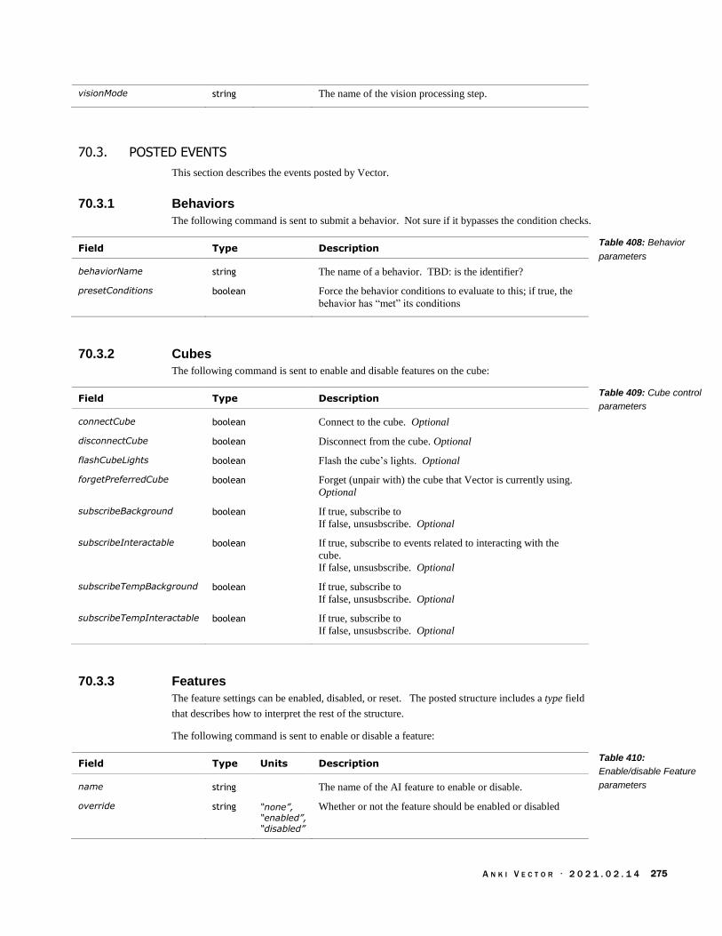
A N K I V E C T O R · 2 0 2 1 . 0 2 . 1 4 275
visionMode string The name of the vision processing step.
70.3. POSTED EVENTS
This section describes the events posted by Vector.
70.3.1 Behaviors
The following command is sent to submit a behavior. Not sure if it bypasses the condition checks.
Field Type Description
behaviorName string The name of a behavior. TBD: is the identifier?
presetConditions boolean Force the behavior conditions to evaluate to this; if true, the
behavior has “met” its conditions
70.3.2 Cubes
The following command is sent to enable and disable features on the cube:
Field Type Description
connectCube boolean Connect to the cube. Optional
disconnectCube boolean Disconnect from the cube. Optional
flashCubeLights boolean Flash the cube’s lights. Optional
forgetPreferredCube boolean Forget (unpair with) the cube that Vector is currently using.
Optional
subscribeBackground boolean If true, subscribe to
If false, unsusbscribe. Optional
subscribeInteractable boolean If true, subscribe to events related to interacting with the
cube.
If false, unsusbscribe. Optional
subscribeTempBackground boolean If true, subscribe to
If false, unsusbscribe. Optional
subscribeTempInteractable boolean If true, subscribe to
If false, unsusbscribe. Optional
70.3.3 Features
The feature settings can be enabled, disabled, or reset. The posted structure includes a type field
that describes how to interpret the rest of the structure.
The following command is sent to enable or disable a feature:
Field Type Units Description
name string The name of the AI feature to enable or disable.
override string “none”, “enabled”,
“disabled”
Whether or not the feature should be enabled or disabled
Table 408: Behavior
parameters
Table 409: Cube control
parameters
Table 410:
Enable/disable Feature
parameters

A N K I V E C T O R · 2 0 2 1 . 0 2 . 1 4 276
type string “override”
The following command is sent to reset all of the features to their default state:
Field Type Description
type string “reset”
70.3.4 Habitat
The following command is sent to force Vector to think that he is in or out of his habitat:
Field Type Description
forceHabitatState string The state to set the habit state to. See Table 378: Habitat
state enumeration for possible values.
70.3.5 Intent
The following command is sent to submit an intent to AI engine:
Field Type Description
intentType string The name of the intent.
request string
70.3.6 Mood
The following command is sent to enable and disable features on the cube:
Field Type Description
Confident float How confident Vector is. -1…1. Optional
Happy float How happy Vector is. -1…1. Optional
Social float How social Vector is feeling. -1…1. Optional
Stimulated float How stimulated Vector is feeling. 0…1. Optional
Trust float How trusting Vector is feeling. 0…1. Optional
70.3.7 NavMap
The following command is sent to request an updated map:
Field Type Description
update boolean True to request an updated map be sent
Table 411: Reset all
features parameters
Table 412: Habitat
setting parameters
Table 413: Intent sensor
event parameters
Table 414: Mood
parameters
Table 415: NavMap
parameters

A N K I V E C T O R · 2 0 2 1 . 0 2 . 1 4 277
70.3.8 Power
The following command is sent to force Vector into (or out of) a power saving state:
Field Type Description
enablePowerSave boolean True if Vector should enter a power save state, false
otherwise
70.3.9 Touch Sensor
The following command is sent to enable and disable the touch sensor:
Field Type Description
enabled string “true” to enable the touch sensor.
“false” to disable the touch sensor.
Optional
resetCount string “true” to reset the touch count. Optional.
Table 416: Power save
parameters
Table 417: Touch
sensor control
parameters

A N K I V E C T O R · 2 0 2 1 . 0 2 . 1 4 278
CHAPTER 17
The Cloud Services
This chapter describes the remote servers that provide functionality for Vector.
JSON document storage server
The crash uploader
The diagnostic logger
The token/certificate system
The natural language processing
71. CONFIGURATION
The server URLs are specified in
/anki/data/assets/cozmo_resources/config/server_config.json
The path to this JSON file is hardcoded in vic-cloud
Element Description & Notes
appkey A base64 token used to communicate with servers.
“oDoa0quieSeir6goowai7f”
check The server to use for connection checks
chipper The natural language processing server
jdocs The remote JSON storage server
logfiles The server to upload log files to
tms The token server where Vector gets authentication items like
certificates and tokens
The URL to upload crash logs to is given in
/anki/etc/vic-crashuploader.env
The URL to automatically download OTA files from is given in
/anki/etc/update-engine.env
The DAS server to contact is given in
/anki/data/assets/cozmo_resources/ config/DASConfig.json
(This path is hardcoded in vic-DASMgr)
Table 418: The cloud
services configuration
file
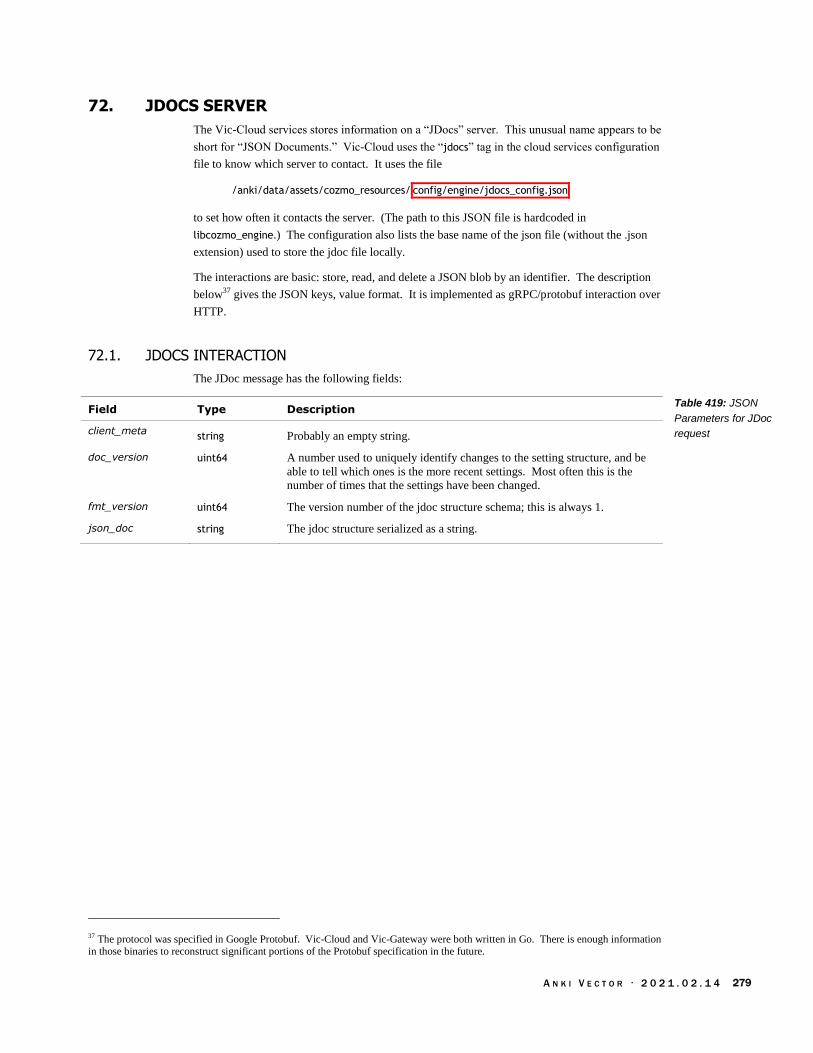
A N K I V E C T O R · 2 0 2 1 . 0 2 . 1 4 279
72. JDOCS SERVER
The Vic-Cloud services stores information on a “JDocs” server. This unusual name appears to be
short for “JSON Documents.” Vic-Cloud uses the “jdocs” tag in the cloud services configuration
file to know which server to contact. It uses the file
/anki/data/assets/cozmo_resources/ config/engine/jdocs_config.json
to set how often it contacts the server. (The path to this JSON file is hardcoded in
libcozmo_engine.) The configuration also lists the base name of the json file (without the .json
extension) used to store the jdoc file locally.
The interactions are basic: store, read, and delete a JSON blob by an identifier. The description
below37 gives the JSON keys, value format. It is implemented as gRPC/protobuf interaction over
HTTP.
72.1. JDOCS INTERACTION
The JDoc message has the following fields:
Field Type Description
client_meta string Probably an empty string.
doc_version uint64 A number used to uniquely identify changes to the setting structure, and be
able to tell which ones is the more recent settings. Most often this is the
number of times that the settings have been changed.
fmt_version uint64 The version number of the jdoc structure schema; this is always 1.
json_doc string The jdoc structure serialized as a string.
37 The protocol was specified in Google Protobuf. Vic-Cloud and Vic-Gateway were both written in Go. There is enough information in those binaries to reconstruct significant portions of the Protobuf specification in the future.
Table 419: JSON
Parameters for JDoc
request

A N K I V E C T O R · 2 0 2 1 . 0 2 . 1 4 280
72.2. DELETE DOCUMENT
72.2.1 Request
The DeleteDocReq request message has the following fields:
Field Type Description
account string The account to read from
doc_name string The name of the document to delete.
thing string The thing id is a ‘vic:’ followed by the serial number
72.2.2 Response
The DeleteDocResp response message has the following fields:
Field Type Description
latest_version uint64 The current version of the document in the repository.
status string
72.3. ECHO TEST
72.3.1 Request
EchoReq
data
72.3.2 Response
EchoResp
data
Table 420: JSON
Parameters for JDoc
request
Table 421: JSON
Parameters for JDoc
request

A N K I V E C T O R · 2 0 2 1 . 0 2 . 1 4 281
72.4. READ DOCUMENTS
72.4.1 Request
The ReadDocsReq request message has the following fields
Field Type Description
account string The account to read from
items [] Array of names document names(?)
thing string The thing id is a ‘vic:’ followed by the serial number
72.4.2 Response
ReadDocsResp
items
The ReadDocsResp response message has the following fields:
Field Type Description
items ReadDocsReq_item[]
The documents (?)
72.5. READ DOCUMENT ITEM
72.5.1 Request
The ReadDocsReq_Item request message has the following fields
Field Type Description
doc_name string The name of the document to request
my_doc_version UInt64 The version to retrieve(?)
72.5.2 Response
The ReadDocsResp_Item response message has the following fields:
Field Type Description
doc JDoc The document structure.
status string
Table 422: JSON
Parameters for JDoc
read request
Table 423: JSON
Parameters for JDoc
read response
Table 424: JSON
Parameters for JDoc
read item request
Table 425: JSON
Parameters for JDoc
read item response

A N K I V E C T O R · 2 0 2 1 . 0 2 . 1 4 282
72.6. WRITE DOCUMENT
72.6.1 Request
The WriteDocReq request message has the following fields
Field Type Description
account string The account to write to
doc JDoc The document structure.
doc_name string The name of the document to write.
thing string The thing id is a ‘vic:’ followed by the serial number
72.6.2 Response
The WriteDocResp response message has the following fields:
Field Type Description
latest_doc_version uint64 The current version of the document in the repository.
status string
72.7. OTHER AREAS
The vic-cloud service and the remove server perform periodic performance tests to check latency of
the DNS servers and cloud data servers.
Table 426: JSON
Parameters for JDoc
write request
Table 427: JSON
Parameters for JDoc
write response
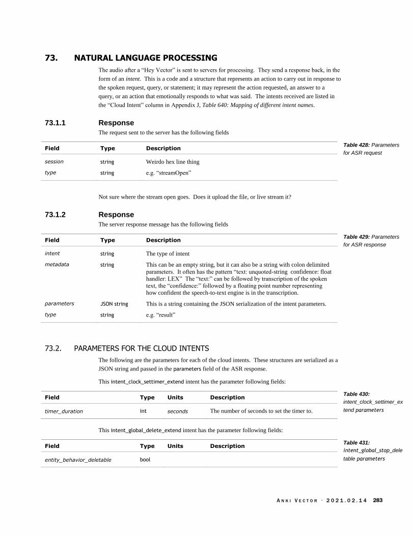
A N K I V E C T O R · 2 0 2 1 . 0 2 . 1 4 283
73. NATURAL LANGUAGE PROCESSING
The audio after a “Hey Vector” is sent to servers for processing. They send a response back, in the
form of an intent. This is a code and a structure that represents an action to carry out in response to
the spoken request, query, or statement; it may represent the action requested, an answer to a
query, or an action that emotionally responds to what was said. The intents received are listed in
the “Cloud Intent” column in Appendix J, Table 640: Mapping of different intent names.
73.1.1 Response
The request sent to the server has the following fields
Field Type Description
session string Weirdo hex line thing
type string e.g. “streamOpen”
Not sure where the stream open goes. Does it upload the file, or live stream it?
73.1.2 Response
The server response message has the following fields
Field Type Description
intent string The type of intent
metadata string This can be an empty string, but it can also be a string with colon delimited
parameters. It often has the pattern “text: unquoted-string confidence: float
handler: LEX” The “text:” can be followed by transcription of the spoken
text, the “confidence:” followed by a floating point number representing
how confident the speech-to-text engine is in the transcription.
parameters JSON string This is a string containing the JSON serialization of the intent parameters.
type string e.g. “result”
73.2. PARAMETERS FOR THE CLOUD INTENTS
The following are the parameters for each of the cloud intents. These structures are serialized as a
JSON string and passed in the parameters field of the ASR response.
This intent_clock_settimer_extend intent has the parameter following fields:
Field Type Units Description
timer_duration int seconds The number of seconds to set the timer to.
This intent_global_delete_extend intent has the parameter following fields:
Field Type Units Description
entity_behavior_deletable bool
Table 428: Parameters
for ASR request
Table 429: Parameters
for ASR response
Table 430:
intent_clock_settimer_ex
tend parameters
Table 431:
intent_global_stop_dele
table parameters

A N K I V E C T O R · 2 0 2 1 . 0 2 . 1 4 284
This intent_global_stop_extend intent has the parameter following fields:
Field Type Units Description
entity_behavior_stoppable bool
This intent_imperative_eyecolor_extend intent has the parameter following fields:
Field Type Units Description
eye_color string The name of the color to set the eye color to
This intent_imperative_volumelevel_extend intent has the parameter following fields:
Field Type Units Description
volume_level string
This intent_knowledge_response_extend intent has the parameter following fields:
Field Type Description
answer string The text to be spoken
answer_type string “NoResultCommand”
query_tyext string The text of the question asked
This intent_message_playmessage_extend intent has the parameter following fields:
Field Type Units Description
given_name string The name of the person to send the message to
This intent_names_username_extend intent has the parameter following fields:
Field Type Units Description
username string The name of the user
This intent_photo_take_extend intent has the parameter following fields:
Field Type Units Description
entity_photo_selfie string Empty string if taking a photo, “photo_selfie” if
taking a selfie.
Table 432:
intent_global_stop_ext
end parameters
Table 433:
intent_imperative_eyeco
lor_extend parameters
Table 434:
intent_imperative_volum
elevel_extend
parameters
Table 435:
intent_knowledge_respo
nse_extend parameters
Table 436:
intent_message_playme
ssage_extend
parameters
Table 437:
intent_names_username
_extend parameters
Table 438:
intent_photo_take_exten
d parameters

A N K I V E C T O R · 2 0 2 1 . 0 2 . 1 4 285
This intent_weather_extend intent has the parameter following fields:
Field Type Units Description
condition string The current weather conditions. One of “Clear”,
“Cloudy”, “Cold”, “Rain”, “Snow”, “Stars”,
“Sunny”, “Thunderstorms”, or “Windy”
is_forecast string “false” or “true”
“false” if it is the current weather conditions; “true”
if forecasted weather conditions.
local_datetime string The local time (where the weather conditions
apply) in UTC ISO 8601 format.
speakable_location_string string The location name that Vector could employ in his
verbal description of the temperature.
temperature string degrees The current or forecasted temperature, in the given
units.
temperature_unit string F or C, for the units
74. LOGS AND TRACE DATA
There are 4 log uploading systems
Two log uploaders
A crash minidump log uploader
DAS event logs upload
74.1. LOG UPLOADER
Vector has two different log uploaders:
74.1.1 vic-log-upload
vic-log-upload sends logs to an Amazon S3 server, with the bucket information in the server-
config.json file. See chapter 33, section 145.3 Gathering logs, regularly for more details on this
file.
74.1.2 vic-logmgr-upload
This section describes how logs are uploaded by vic-logmgr-upload. That program is not called.
See chapter 33, section 145.2 Vic-logmgr-upload for more details.
The logs are uploading by performing a HTTP PUT to the server. The URL is the “logfiles” URL
in the server configuration file, with a file name of the form:
victor- electronic serial number - timestamp - pid .log.gz
Where the time stamp has the following format:
year-month-day-hour-minute-seconds
Table 439:
intent_weather_extend
parameters

A N K I V E C T O R · 2 0 2 1 . 0 2 . 1 4 286
The HTTP headers are:
HTTP header Description
Anki-App-Key The appKey from the server configuration file.
Usr-RobotESN Vector’s serial number
Usr-RobotOSRevision The OS revision string from /etc/os-version-rev
Usr-RobotOSVersion The OS version string from /etc/os-version
Usr-RobotRevision The Anki revision string from /anki/etc/revision
Usr-RobotTimestamp The time of Vector’s internal clock.
Usr-RobotVersion The Anki version string from /anki/etc/version
Usr-Username
74.2. CRASH UPLOADER
Minidumps produced after a crash are uploaded to a backtrace.io server using a HTTP POST by
the vic-crashuploader program. The HTTP headers are:
Form fields Description
attachment_messages.log The “.log” file associated with the minidump. This is optional;
only included if /run/das_allow_upload exists
hostname ${hostname}
robot.esn Vector’s serial number
robot.os_version The OS version string from /etc/os-version
robot.anki_version The Anki version string from /anki/etc/version
upload_file The minidump “.dmp” file
The URL (including the key) is set in the vic-crashuploader configuration file. See chapter 33
section 145.7 Crash Logs for more details on vic-crashuploader and how minidumps are acquired.
Table 440: Log upload
HTTP header fields
Table 441: Crash
upload form fields

A N K I V E C T O R · 2 0 2 1 . 0 2 . 1 4 287
74.3. DAS MANAGER
DAS Manager uploads event traces to an Amazon “Simple Queue Service” (SQS) server, with the
blobstore specified in the “logfiles” field of the server_config.json configuration file. Amazon’s
API uses the following key/value pairs in a URL encoded form:
Keys Value
Action SendMessage
MessageAttribute.1.Name DAS-Transport-Version
MessageAttribute.1.Value.DataType Number
MessageAttribute.1.Value.StringValue 2
MessageAttribute.2.Name Content-Encoding
MessageAttribute.2.Value.DataType String
MessageAttribute.2.Value.StringValue gzip, base64
MessageAttribute.3.Name Content-Type
MessageAttribute.3.Value.DataType String
MessageAttribute.3.Value.StringValue application/vnd.anki.json; format=normal;
product=vic
MessageBody
Version 2012-11-0538
Note: there may be a body of compressed JSON data. These values are hardcoded in vic-dasmgr
and libcozmo_engine. The URL is set in the vic-dasmgr configuration file.
Each entry of the upload JSON data includes a profile id; it can be tied to the user account, but
Unless you create an account and log in, Analytics Data is stored under a unique ID and
not connected to you.
See Chapter 33, section 147.2 DAS for more information on the DAS events and configuration file.
75. REFERENCES AND RESOURCES
Davis, Jason; File Attachments in Backtrace, Backtrace.io
https://help.backtrace.io/en/articles/1852523-file-attachments-in-backtrace
38 This date is very far in the past, before Vector or Cozmo were developed. This was the time frame of the Overdrive product development.
Table 442: DAS
Manager SQS key-value
pairs

A N K I V E C T O R · 2 0 2 1 . 0 2 . 1 4 288
[This page is intentionally left blank for purposes of double-sided printing]

A N K I V E C T O R · 2 0 2 1 . 0 2 . 1 4 289
PART IV
Advanced Functions
This part describes items that are Vector’s primary function.
AUDIO INPUT. A look at Vector’s ability to hear spoken commands, and ambient sounds.
IMAGE PROCESSING. Vector vision system is sophisticated, with the ability to recognize
marker, faces, and objects; to take photographs, and acts as a key part of the navigation
system.
MAPPING, NAVIGATION. A look at Vector’s mapping and navigation systems
ACCESSORIES. A look at Vector’s home (charging station), companion cube and custom
objects.
drawing by Steph Dere

A N K I V E C T O R · 2 0 2 1 . 0 2 . 1 4 290
[This page is intentionally left blank for purposes of double-sided printing]

A N K I V E C T O R · 2 0 2 1 . 0 2 . 1 4 291
CHAPTER 18
Audio Input
This chapter describes the sound input system:
The audio input
The audio filtering, and triggering of the speech recognition
76. AUDIO INPUT
The audio input is used to both give Vector verbal interaction, and to give him environmental
stimulation:
Automatic Speech
Recognition &
Language
understanding
Spatial Audio
Processing
Noise
Reduction
Voice Activity
Detector
4 MEMs
Microphones
4 MEMs
Microphones
4 MEMs
Microphones
Feature
extraction
Beats per minute
Behavior &
Animation
Engines
Wake Word
SDK
applications
Opus
CODEC
Spatial audio processing localizes the sound of someone talking from the background
music.
The feature extraction detects the ambient activity, and the tempo of the music. If the
tempo is right, Vector will dance to it. This also provides basic stimulation to Vector.
Noise reduction makes for the best sound.
Voice activity detector usually triggered off of the signal before the beam-forming.
A wake word is used to engage the automatic speech recognition system. Note: the wake
word is also referred to as the trigger word.
A CODEC is used to compress the audio before sending it to the remote server; Alexa
Voice Services use the Opus audio CODEC.
The speech recognition system is on a remote server. The audio sent to the automatic
speech recognition system is compressed to reduce data usage.
Figure 64: The audio
input functional block
diagram

A N K I V E C T O R · 2 0 2 1 . 0 2 . 1 4 292
The responsibility for these functions is divided across multiple processes and boards in Vector:
Chipper & Lex
Automatic Speech
Recognition & Language
understanding
UART
Body-Board
SDK applicationsVic-Gateway
4 MEMs
Microphones
4 MEMs
Microphones
4 MEMs
Microphones
Vic-Anim
Vic-Robot
Vic-Spine
SPI
Alexa
Vic-Engine
Alexa Voice Services
Vic-Cloud
Note: providing the audio input to the SDK (via Vic-gateway) was never completed. It will be
discussed based on what was laid out in the protobuf specification files.
The audio processing blocks, except where otherwise discussed, are part of Vic-Anim. These
blocks were implemented by Signal Essence, LLC. They probably consulted on the MEMs
microphones and their configuration. Although the Qualcomm family includes software support
for these tasks, as part of the Hexagon DSP SDK; it is believed that Signal Essence did not take
advantage of it.
76.1. THE MICROPHONES AND CONVERSION TO AUDIO SAMPLES
The microphone array is 4 far-field MEMs PDM microphones that sample the incoming sound
and transfer the samples to body-board. (See Chapter 4 section 11.4.6 PDM Microphones for a
description of the low-level bit-moving.)
DMA Buffer
UART Tx
Buffer
DMA Buffer
4 MEMs
Microphones
2 MEMs
Microphones
4 MEMs
Microphones
2 MEMs
Microphones
Head BoardSeparate into
left & right
Separate into
left & right
RightFilter
LeftFilter
RightFilter
LeftFilter
PCM
The body-board samples each microphone at 1.5 M samples/sec – but at only 1 bit/sample! It
passes the stream of samples thru a filter, produces audio at 15,625 samples/sec, with 16
bits/sample (effectively it may have anything in the range 10 to 16 bits, and padding out the rest).
The filter also acts as a low pass filter, removing high frequency sampling artifacts. The most
important part is that it preserves “phase information” so that the beam forming and direction
finding steps work well. (More on this in a later section).
The audio samples are transferred to the Vic-spine module (part of Vic-robot) in regular
communication with the head-board. The message from the body-board to the head board for
sending 4 channels of audio samples includes 80 samples per channel (320 samples total).
Figure 65: The audio
input architecture
microphone array
architecture
Figure 66: Sampling
the microphones and
converting to PCM
format

A N K I V E C T O R · 2 0 2 1 . 0 2 . 1 4 293
The samples are extracted from the received message and forward to the Vic-Anim process. The
software treats the audio as if it its sample rate was 16,000 samples/sec. (“As a result, the pitch is
altered by 2.4%.”) The signal processing is done in chunks of 160 samples.
76.1.1 The likely operation
Each SPI is configured to run at 3Mb/s (the slowest it can drive the microphones), using a DMA
to transfer data into a buffer (~1536 bytes in size). The DMA’s are configured to use circular
mode, where they never stop; instead they automatically wrap around to the start of the buffer
after filling it. Because both SPI’s are tied together, only one DMA is configured to generate
interrupts.
The input system triggers the SPIs to start gathering the data into their respective buffers. After
that:
1. When the DMA has filled half of the buffer, it generates an interrupt. The filtering on all
four channels is initiated for this half of the buffer, puts the result into the outgoing
message buffer.
2. When the DMA has filled the second half of the buffer, it generates and end of transfer
interrupt. The filtering on all four channels is initiated for this second half of the buffer,
again putting the result into the outgoing message buffer. (In the mean time, the DMA has
automatically looped back to the start of buffer and kept the SPI transferring the bits.)
3. If the outgoing buffer is full (i.e., after the DMA buffers have been filled twice), the UART
transmit is initiated.
It is possible that the firmware uses two buffers, one that is filled by the filtering, and another that
is sending data on the UART, and swapping every time it’s filled. It is more likely that only that
the body-board fills the same output buffer as data is being sent from it to the head-board, to save
on memory usage. Although the SPI is 2-3x faster than the UART, the filter stage takes 6 bits for
every for every data bit that is sent to the head board. The UART can effectively send data at least
2x faster than the SPIs receive.
Each microphone is driven at 1.5 M samples/sec (half the SPI clock frequency). The ratio
between this input sample rate and the output sample rate (15,625) – called the decimation
– is 96:1.
Since it takes 96 input samples (bits) to get one output 16-bit sample39, the bit-rate
reduction is 6:1.
Altogether the audio sampling, filtering/decimation, and sending to the head-board uses at least
4KB of the MCU’s 8KB of RAM.
39 The filtering may give the audio samples an effective range ~11 or 12 bits. The Customer Care Information Screen (CCIS) shows the microphones to be about 1024 when quiet.
transferring 4Mb/s
from 4 microphones
and filtering it into
PCM audio

A N K I V E C T O R · 2 0 2 1 . 0 2 . 1 4 294
76.2. SPATIAL AUDIO PROCESSING
The spatial audio processing uses multiple microphones to pick-out the desired sound signal and
cancel out the unwanted. Note: The spatial audio processing is bypassed until voice activity has
been detected. The direction finding can isolate the audio from 12 different directions, each 30°
wide:
30°
Has a signal
strength in that
direction, and audio
stream
Note: forward is 0°.
The direction finding and isolation is typically a two-stage process:
Source
localizationBeam forming
Noise
reduction
Feature
extraction
Audio
Samples
THE SOURCE LOCALIZATION estimates direction of arrival of the person talking.
BEAM-FORMING combines the multiple microphone inputs to cancels audio coming from other
directions.
The output of this stage includes:
A histogram of the directions that the sound(s) in this chunk of audio came from. There
are 12 bins, each representing a 30° direction.
A measure of the background noise
The direction that is picked for the origin of the sound of interest
A confidence value for that direction
The sound stream isolated for the picked direction, in the form of 160 16-bit PCM audio
samples.
See also:
Chapter 15, section 50.5 Audio Processing Mode for a potential method to enable and
disable the spatial sound processing;
Chapter 15, section 50.4 Audio Feed (from the Microphones) for potential access to the
audio stream via the HTTPS API.
Figure 67: The audio
can be isolated into
one of 12 different
directions
Figure 68: Typical
spatial audio
processing flow

A N K I V E C T O R · 2 0 2 1 . 0 2 . 1 4 295
76.3. NOISE REDUCTION
Noise reduction identifies and eliminates noise and echo in the audio input:
Voice
Activity
Detector
Vic-Cloud
Spatial
Audio
processing
Echo
cancellation
Noise
suppression
Auto Gain
control
ACOUSTIC ECHO CANCELLATION cancels slightly delayed repetitions of a signal.
NOISE SUPPRESSION is used to eliminate noise.
The combination of spatial processing and noise reduction gives the cleanest sound (as compared
with no noise reduction and/or no spatial processing).
Vector is also likely to ignore the microphones while sounds are playing.
76.4. DETECTING ACTIVITY
Vector includes a module to detect sound activity (as distinguished from noise). The sound
reaction behavior uses this to stimulate Vector from his sleep, get his attention, and encourage him
to be more active. One way this could be done is through a set of filters to measure power levels:
Low Pass
filterFilter
Noise floor
Sound Level
Power
Threshold
Percentile
Filter
latest Sound
detected
The TBD {loudness estimator} might use an algorithm similar to the following steps:
1. First, the sound filter is to make the sound better reflect how our ears hear it, and/or
remove elements that would cause false triggers. Two popular approaches are “equal
loudness” by David Robinson and “a-weighting.” Both take into account how people
perceive sounds loudness by giving less weight to some frequencies regions (the very low
and high), and more weight to others (the very middle).
2. Every few tens or hundreds of milliseconds the “power” level of the sound is computed.
This is the logarithm of the root mean square (RMS) of the filtered values –squaring each
value, averaging that, taking the square root and then computing its logarithm. Often this
calculation is rearrange to be a bit faster, by skipping the square root and adjusting the
logarithm scaling factor.
3. The computed power can then be compared against an estimate of the noise floor (the
generic ambient sound level), to see if there is some activity, even the beat of a music.
4. The power levels are also tracked for a second (or a few seconds). The values could be
averaged. Or the values could be sorted, from smallest to largest. The first value ~95% of
Figure 69: Typical
audio noise reduction
flow
Figure 70: Sound and
noise level estimator,
and activity detector

A N K I V E C T O R · 2 0 2 1 . 0 2 . 1 4 296
the way into the sorted before could be used as the current overall sound level. (This
avoids taking the loudest transient sound.).
The noise floor could be taken from the lowest value in the sorted array (step 4) – or the value that
is, say, 5% into the array can be treated as the noise floor. Or it could be estimated by taking a low
pass filter on the lowest values. The key is that so even though the sound level is increasing, the
noise level is it is slow move up. A low pass filter has the advantage of not taking a large amount
of memory – using a large the percentile filter window (and using the lowest value in it) would
take much more memory to prevent confusing several minutes of music with silence.
76.5. BEAT DETECTION
The details of how Vector’s beat detection is implemented are not known, but beat detection is a
common signal processing task. This section describes a typical implementation.
The beat detection is made of two related sub-functions. The first is a fast detector that can be used
for quick dance responses in time to the music. The second finds the tempo – the beats per minute
– of the music, which is also good indication that there is music playing (and not other activity).
Note: See chapter 25, section 111.1.1 Pitch tracker for how to find the pitch.
76.5.1 A quick beat-detector
A simple responsive beat detector works by filtering the sound thru a band pass filter (say with a
range of 100 Hz to 350 Hz) and then look for the magnitude to above a threshold:
Noise
ReductionDetect beat
Band Pass
Filter
Once a beat is detected, it holds off sending another event until the signal has dropped below a
threshold for at least half a second or more. Another timer may be used to tell when the music has
stopped: the timer is reset whenever a new beat is detected, and expires if a beat has not been
detected for a few seconds.
Although simple to implement, loud noises can trick it, and it is not very good at measuring the
tempo (the speed of the music in beats per second).
76.5.2 Tempo
A more accurate approach is to use a spectrogram to measure the tempo. The beats are very low
frequency signals in the spectrograph. Music might be in the range of 50-110bpm (0.7Hz to 2Hz).
The approach is to search the spectrogram in this frequency range for signals above a minimum
threshold (to screen out generic sounds), and pick the strongest.
Low Pass
FilterFFT
Sound
samplesPick tempo
Scoreboard
Down
sample
Figure 71: Typical
beat detection
Figure 72: Typical
tempo measurement

A N K I V E C T O R · 2 0 2 1 . 0 2 . 1 4 297
This will use an FFT to compute the spectrogram. It will need a wide window – a few seconds
wide – to detect the beats, since they are at such a low frequency. This is down-sampled to s lower
sampling rate – this reduces the memory required, and the amount of computation required to fit
the task at hand. The basic algorithm is:
1. Take the sound input, and perform a low pass filter in it; this eliminates aliasing noises that
can come down-sampling
2. Next is to down sample the audio to only a few samples per second, and hold the results in
a window a few seconds wide.
3. Periodically – every few seconds – an FFT is performed to create a new spectrograph.
Note: the window can be “rolling” (instead of being thrown out and repopulated each time)
to allow faster updates to the measured beats.
4. The FFT results are examined to find frequencies with a power above a threshold. These
are the potential beats (in Hz)
5. The beats are then tracked in a scoreboard. The scoreboard tracks which beats are
consistent and which are transitory. The beat-rates that haven’t been heard in a while are
discounted or cleared out with time.
6. A tempo, perhaps the highest persistent beats/minute, is then reported as the most likely
rate.
The drawback of this approach is that is “slow” and can’t be used to dance in time to the music
with. The time window to find slower beats (the ones about every second) is very long, it can take
a few seconds before it will have anything about the music beats.
76.5.3 Beat Detector Outputs
The beat detection modules produce several JSON structures for developer websocket and internal
use. The main structure has the following fields:
Field Type Units Description
beatInfo BeatInfo[] Information on the beat (or different possible
tempos present in the music)
detectorInfo DetectorInfo Information from the detector on the beats
The DetectorInfo structure has the following fields:
Field Type Units Description
beatDetected boolean True if a beat has just been detected.
latestConf float How confident the analysis is in the tempo
measurement.
latestTempo_bpm float beats /
minute
The measured number of beats per minute.
possibleBeatDetected string “yes” or “no”
Whether or not a potential music beat was
detected.
Table 443: Beat
detection event
parameters
Table 444: DetectorInfo
parameters

A N K I V E C T O R · 2 0 2 1 . 0 2 . 1 4 298
The BeatInfo structure has the following fields:
Field Type Units Description
aboveThresh boolean Are the beats per minute above a threshold??
conf float How confident the analysis is in the tempo
measurement.
tempo_bpm float beats /
minute
The measured number of beats per minute.
timeSinceBeat float seconds The number of seconds since the last beat; this can
useful for deciding that the music has stopped.
76.6. RECORDING TO A FILE
The microphone module can store sound – either raw or processed – to a wave file. This may be
for diagnostic purposes, left over as part of testing different microphone settings.
76.7. VOICE ACTIVITY DETECTOR AND WAKE WORD
The voice activity detector is given cleaned up sound from multiple microphones without beam-
forming. When it detects voice activity, then the spatial audio processing is fully enabled.40
Detecting that speaking is going on is more refined and specific than simply detecting that there is
some interesting sound.
The voice activity detector and the wake word are used so that downstream processing – the wake
word detection, and the automatic speech recognition system – are not engaged all the time. They
are both expensive (in terms of power and CPU load), and the speech recognition is prone to
misunderstanding.
When the voice activity detector triggers – indicating that a person may be talking – the spatial
audio processing is engaged (to improve the audio quality) and the audio signals are passed to the
Wake Word Detector.
The detector for the “Hey, Vector” is provided by Sensory, Inc. Pryon, Inc provided the detector
for “Alexa.” 41 The recognition is locale dependent, detecting different wake words for German,
etc. It may be possible to create other recognition files for other wake words.
When the “Hey, Vector” wake word is heard,
1. A connection (via Vic-Cloud) is made to the remote speech processing server for automatic
speech recognition.
2. If there was an intent found (and control is not reserved), the intent is mapped to a local
behaviour to be carried out. This is described in a later section.
76.7.1 Wake work configuration file
The configuration file for the wake word is located at:
/anki/data/assets/cozmo_resources/ config/micData/micTriggerConfig.json
40 Vector’s wake word detection, and speech recognition is pretty hit and miss. Signal Essence’s demonstration videos show much
better performance. The differences are they used more microphones and the spatial audio filtering in their demos. . Version 1.7
improved echo cancellation and wake word detection. 41 This appears to be standard for Alexa device SDKs.
Table 445: BeatInfo
parameters

A N K I V E C T O R · 2 0 2 1 . 0 2 . 1 4 299
This file has dictionary structure with the following fields:42
Field Type Description & Notes
alexa_pryon WakeWordLocale[]
The wake word speech recognition models for Alexa in each of
the supported locales, using models for Pryon’s toolkit (the default
for Alexa Voice Services).
alexa_thf WakeWordLocale []
The wake word speech recognition models for Alexa in each of
the supported locales, using models for Sensory’s Truly
HandsFree toolkit.
hey_vector_thf WakeWordLocale []
The wake word speech recognition models for “Hey Vector” in
each of the supported locales, using models for Sensory’s Truly
HandsFree toolkit
A WakeWordLocale is used to map a language locale to the wake word recognition models to use.
This structure has the following fields:
Field Type Description & Notes
defaultModelType string e.g. “size_500kb” or “size_1mb”
locale string The IETF language tag of the human companion’s language
preference – American English, UK English, Australian English,
German, French, Japanese, etc.
default: “en-US”
modelList WakeWordModel[] The wake word speech recognition models, in a variety of sizes
Each WakeWordModel provides a set of word recognition models that can be used. The structure
has the following fields:
Field Type Description & Notes
dataDirectory string The path (relative to the TBD) holding the recognition models.
defaultSearchFileIndex uint The index of the model (in searchFileList) to use by default.
modelType string e.g. “size_500kb” or “size_1mb”
netFileName string Name of a file.
searchFileList WakeWordFile[] The wake word speech recognition models, in a variety of sizes
Each WakeWordFile structure has the following fields:
Field Type Description & Notes
searchFileIndex uint The index of the model (in searchFileList) to use by default.
searchFileList string The name of the file…? (relative to the data directory). “NA” if a
file name is not applicable.
42 The names of the structures here were created for clarity; they are not actually used in the files.
Table 446: The
micTriggerConfig
JSON structure
Table 447: The
WakeWordLocale
JSON structure
Table 448: The
WakeWordLocale
JSON structure
Table 449: The
WakeWordLocale
JSON structure

A N K I V E C T O R · 2 0 2 1 . 0 2 . 1 4 300
76.8. CONNECTIONS WITH VIC-GATEWAY AND SDK ACCESS
An application has access to the wake-word events and the received user intent events as they
occur. When the “Hey, Vector” wake word is heard,
1. A WakeWordBegin (see Chapter 14 section 50.2.3 WakeWord) event message is posted to
Vic-Engine and Vic-Gateway. Vic-Gateway may forward the message on to a connected
application.
2. A StimulationInfo (see Chapter 14, section 46.2.2 StimulationInfo) event message, an
emotion event “ReactToTriggerWord,” is posted to Vic-Gateway for possible forwarding to
a connected application.
3. A WakeWordEnd (see Chapter 14 section 50.2.3 WakeWord) event message is sent (to Vic-
Gateway for possible forwarding to a connected application) when the Vic-cloud has
received a response back. If control has not been reserved, and intent was received, the
intent JSON data structure is included.
4. If there was no intent found, a StimulationInfo (see Chapter 14, section 46.2.2
StimulationInfo) event message is post (to Vic-Gateway), with an emotion event such as
NoValidVoiceIntent
5. If there was an intent found (and control is reserved), a UserIntent (see Chapter 14, section
50.2.2 UserIntent) event is posted to Vic-Gateway for possible forwarding to a connected
application. In this case, the intent will not be carried out.
An external application can send an intent to Vector using the AppIntent command (see Chapter
15, section 50.3 App Intent).
76.8.1 Audio Stream
It is clear that Anki made provisions to connect the audio stream to Vic-Gateway but were unable
to complete the features before they ceased operation. The SDK would have been able to:
Enable and disable listening to the microphone(s)
Select whether the audio would have the spatial audio filter and noise reduction processing
done on it.
Include the direction of sound information from the spatial audio processing (see section
76.2 Spatial audio processing)
1600 audio samples; Note: this is 10x the chunk size of the internal processing size

A N K I V E C T O R · 2 0 2 1 . 0 2 . 1 4 301
77. CLOUD SPEECH RECOGNITION
The audio stream (after the “Hey Vector”) sent to a group of remote servers for processing. The
servers perform automatic speech recognition (ASR), language understanding steps, and craft a
response.
Vic-Cloud
Speech recognition
(ASR)
· Words· Tone· Intent
Language
understanding
· Words· Tone· Intent· Referred to Entities
Dialog Manager
· Forms response
What the user said is mapped to a user intent. This is a code and structure that represents an action
to carry out in response to the spoken request, query, or statement; it may represent the action
requested, an answer to a query, or an action that emotionally responds to what was said. The
intent includes some supporting information – the colour to set the eyes to, for instance. Many of
the phrase patterns and the intent they map to can be found in Appendix J. The intent may be
further handled by Anki servers; the intent is eventually sent back to Vector.
The intent system does some replacement on the intent names and parameters43 from the cloud and
SDK application to names used internally within Vector’s engine.
Chipper, Lex, etc
Automatic Speech
Recognition & Language
understanding
Intent name and
parameter
substitution
SDK applicationsVic-Gateway
Vic-Cloud
Intent name and
parameter
substitution
Behavior /
Coordinator
It uses separate tables for the intents passed by the cloud and those passed from an SDK
application. With the cloud based intent,
1. Looks up to see if there is a rule matching the name of the passed intent. If there is no
match, the intent (may be) is passed to the next stage. If the internal intent name associated
with the rule will be used, and
2. Each of the passed intent parameter names is checked to see if the name should be changed
to an internal name. If so it is changed to the internal name; otherwise the parameter’s
passed name is (probably) used.
43 The complexity suggests that the development of the server, mobile application and Vector were not fully coordinated and needed this to bridge a gap.
Figure 73: Typical
speech recognition
processes
Figure 74: The
filtering of intents

A N K I V E C T O R · 2 0 2 1 . 0 2 . 1 4 302
The intents passed by the SDK application also go thru a filtering phase:
1. Looks up to see if there is a rule matching the name of the passed intent. If there is no
match, the intent is discarded. If the internal intent name associated with the rule will be
used, and
2. Each of the passed intent parameter names is checked to see if the name should be changed
to an internal name. If so it is changed to the internal name; otherwise the parameter is
discarded.
The intent is also checked to see if it is enabled. Each intent can be associated with a feature flag;
if it is, the flag is looked up to see if the corresponding feature is enabled. (see also Chapter 30
section 134 Feature Flags).
An intent may initiate a behavior, or a coordinator. A coordinator is receptive to further intents in
addition to physical stimulation.
77.1. INTENT PARAMETERS
The global_delete intent has the parameter following fields:
Field Type Units Description
what_to_stop string
The global_stop intent has the parameter following fields:
Field Type Units Description
what_to_stop string
This imperative_eyecolor_specific intent has the parameter following fields:
Field Type Units Description
eye_color string The name of the color to set the eye color to
This imperative_volumelevel intent has the parameter following fields:
Field Type Units Description
volume_level string
This knowledge_response intent has the parameter following fields:
Field Type Units Description
answer string The text to be spoken(?)
query_text string The text of the question asked(?)
Table 450:
global_delete
parameters
Table 451: global_stop
parameters
Table 452:
imperative_eyecolor_sp
ecific parameters
Table 453:
imperative_volumelevel
parameters
Table 454:
knowledge_response
parameters

A N K I V E C T O R · 2 0 2 1 . 0 2 . 1 4 303
This meet_victor intent has the parameter following fields:
Field Type Units Description
username
This message_playback intent has the parameter following fields:
Field Type Units Description
given_name string The name of the person to send the message to
The set_timer intent has the parameter following fields:
Field Type Units Description
time_s int seconds The number of seconds to set the timer to
The take_a_photo intent has the parameter following fields:
Field Type Units Description
empty_or_selfie string Empty string if taking a photo, “photo_selfie” if
taking a selfie.
This test_name intent has the parameter following fields:
Field Type Units Description
name string
This test_timeWithUnits intent has the parameter following fields:
Field Type Units Description
time uint
units string
Table 455: meet_victor
parameters
Table 456:
message_playback
parameters
Table 457: set_timer
parameters
Table 458:
take_a_photo
parameters
Table 459: test_name
parameters
Table 460:
test_timeWithUnits
parameters

A N K I V E C T O R · 2 0 2 1 . 0 2 . 1 4 304
This weather_response intent has the parameter following fields:
Field Type Units Description
condition string The current weather conditions. One of “Clear”,
“Cloudy”, “Cold”, “Rain”, “Snow”, “Stars”,
“Sunny”, “Thunderstorms”, or “Windy”
isForecast string “false” or “true”
“false” if it is the current weather conditions; “true”
if forecasted weather conditions.
localDateTime string The local time (where the weather conditions
apply) in UTC ISO 8601 format.
speakableLocationString string The location name that Vector could employ in his
verbal description of the temperature.
temperature string degrees The current or forecasted temperature, in the given
units.
temperatureUnit string F or C, for the units
77.2. INTENT MAPPING CONFIGURATION FILE
The configuration file holding the mapping of the clouds external intent names and parameters to
those used internally within Vector’s engine is located at:
/anki/data/assets/cozmo_resources/ config/engine/behaviorComponent/user_intent_map
.json
The path is hard coded into libcozmo_engine.so. The file has the following structure:
Field Type Description
simple_voice_responses array of SimpleVoiceResponse
A table that maps the intent received from the cloud intent to
animation and emotion responses.
user_intent_map array of UserIntentMap
A table that maps the intent received from the cloud or
application to the intent name used internally. This includes
renaming the parameters.
unmatched_intent string The intent to employ if cloud’s intent cannot be found in the
table above. Default: “unmatched_intent”
Each of the simple voice response mapping entries has the following structure:
Field Type Description
cloud_intent string The intent name returned by the cloud. See the “Cloud Intent”
column in Appendix J Table 640: Mapping of different intent
names for a list of intent names.
response X The animation and emotion changes that should occur in
response to the intent.
Table 461:
weather_response
parameters
Table 462: The
user_intent_map JSON
structure
Table 463: The simple
voice response JSON
structure

A N K I V E C T O R · 2 0 2 1 . 0 2 . 1 4 305
The response structure has the following fields:
Field Type Description
active_feature string The AI behavior feature that should be activated. See Appendex
H Table 637: The AI behaviour features for a list of AI features.
anim_group string The trigger name of the animation to play.
disable_wakeword_turn bool Default: false. Optional.
emotion_event string The name of the emotion event, describing how this intent affects
Vector's current mood. See Chapter 29 for a description.
Each of the user intent mapping entries has the following fields:
Field Type Description
app_intent string The intent name sent by the SDK application. See the “App
Intent” column in Appendix J Table 640: Mapping of different
intent names for a list of intent names. Optional.
app_substitutions dictionary A dictionary whose keys are the keys provided by the
application’s intent structure, and maps to the keys used internally.
Optional.
cloud_intent string The intent name returned by the cloud. See the “Cloud Intent”
column in Appendix J Table 640: Mapping of different intent
names for a list of intent names.
cloud_numerics array of strings Names of keys that used as parameter values by the behaviour..??
Optional.
cloud_substitutions dictionary A dictionary whose keys are the keys provided by the cloud’s
intent structure, and maps to the keys used internally. Optional.
feature_gate string The name of the feature that must be enabled before this intent can
be processed. Optional.
test_parsing bool Default: true. Optional.
user_intent string The name of the intent used internally within Vector’s engine.
78. REFERENCES AND RESOURCES
https://github.com/ARM-software/ML-KWS-for-MCU
A reference keyword listener for ARM microcontrollers.
https://github.com/MTG/essentia/tree/master/test/src/descriptortests/equalloudness
A reference implementation of an equal-loudness measure
Hydrogen Audio, ReplayGain 1.0 specification, 2018 Nov 19
http://wiki.hydrogenaud.io/index.php?title=ReplayGain_1.0_specification
A detailed description of how the sound loudness can be measured and used to adjust the
volume of music playback.
Note: the filter implementation for audio effects can be very complex; for sound detection it is
very simple.
ST Microelectronics, Reference manual, STM32F030x4/x6/x8/xC and STM32F070x6/xB advanced
ARM®-based 32-bit MCUs, 2017 Apr, Rev 4
https://www.st.com/resource/en/reference_manual/dm00091010-stm32f030x4-x6-x8-xc-and-
stm32f070x6-xb-advanced-arm-based-32-bit-mcus-stmicroelectronics.pdf
Table 464: The
response JSON
structure
Table 465: The intent
mapping JSON structure

A N K I V E C T O R · 2 0 2 1 . 0 2 . 1 4 306
Wikipedia, A-weighting
https://en.wikipedia.org/wiki/A-weighting
Wikipedia, Robinson–Dadson curves
https://en.wikipedia.org/wiki/Robinson%E2%80%93Dadson_curves

A N K I V E C T O R · 2 0 2 1 . 0 2 . 1 4 307
CHAPTER 19
Image Processing
Vector has a clever vision processing system:
Camera operation including calibration
Visual stimulation
Recognizing symbols and specially marked objects
Detecting faces, recognizing people, and estimating emotion
Hand, pet and other object detection
Taking photos
Sending video stream to the SDK
Vision is primarily used for navigation purposes: Recognizing the floor (or ground),
odometry and “simultaneous localization and mapping”
79. CAMERA OPERATION
Vector has a 1280x720 camera with a wide field of view to see around it without moving its head,
similar to how an animal can see a wide area around it by moving its eyes. The camera is
connected to the processor through a MIPI interface. The data from the camera passes to device
drivers, then to a separate daemon service and eventually passes to Vic-engine for the processing:
dev/socket/vic-engine-cam_client0
Python SDK
applicationsVic-Gateway
Vic-engine
CameraMIPI
Recognition
Calibration /
correction
Object &
Face
Detection
Illumination
level
Mapping Photos
Motion
detection
Frame rate
Reducer
Convert to
Gray-Scale &
Shrink the
image
mm-anki-camera
Offboard
Vision EngineVic-Cloud
Figure 75: The
camera architecture

A N K I V E C T O R · 2 0 2 1 . 0 2 . 1 4 308
Vector visually recognizes the following elements in its environment:
Special visual markers; Vector treats all marked objects as moveable… and all other
objects in its driving are as fixed & unmovable.
Faces
Hands
Pets (feature not completed)
Other objects, like fruit, etc. (feature not completed)
LASER pointers (feature not completed)
79.1. CAMERA OPERATION
To reduce computing load the camera frame rate is reduced and the image size is scaled down.
This pattern is common throughout the image processing:
More pixels require much more memory at each stage of image the image processing.
It takes much, much longer (and more power) to process larger frames. There is the added
time to process each of the added pixels. Second, the neural-net models (used for human,
pet and object recognition) are much larger as well, taking much longer to process with the
many stages involved in these models.
That extra processing is among the most power expensive items in Vector, and rapidly
depleting his battery, shortening the time between charges,
The extra processing also generates heat in the head board, and
Image processing tasks don’t need more pixels. There is rarely any improvement in visual
detection from using more pixels or higher frame rates
The software in reduces the frame rate by skipping frames (no fancy interpolation needed). Then
the image is converted to gray scale and scaled down to quarter size (640x360). (This was also the
case with Cozmo.)
79.2. CAMERA CALIBRATION
The camera is calibrated at manufacturing time. This is necessary so that the Vector can accurately
dock with a cube, getting the small lift fingers into the cube’s holes. The calibration primarily
compensates for the image being slightly offset, and unit to unit variation of focal length.
Vector’s camera has ~120° diagonal field of view.44 For comparison the iPhone’s camera has a 73˚
field of view, and the human eye is approximately 95˚. The cropped sensor image has a 90°
horizontal field of view and a 50° vertical field of view.
44 The press release for Vector reported a 120° field of view, but should be discounted as this number does not match the frame field of view numbers given in the SDK documentation.

A N K I V E C T O R · 2 0 2 1 . 0 2 . 1 4 309
Full Frame image
Cropped sensor image
Diagonal field of viewVertical
Field of view
Horizontal Field of view
Vector’s calibration uses focal length instead of field of view. The two values are related:
hfocalLengt
sizesensorwfieldOfVie
2arctan2
The following structure is reported in the robot logs for the camera calibration:
Field Type Description
cx cy
float “The position of the optical center of projection within the image.
It will be close to the center of the image, but adjusted based on
the calibration of the lens at the factory.”
distortionCoeffs float[]
fx fy
float The “focal length combined with pixel skew (as the pixels aren't
perfectly square), so there are subtly different values for x and
y.”
ncols int The width of the image in pixels. The value given is 640.
nrows int The height of the image in pixels. The value given is 360
skew float
Quotes are from Anki Cozmo SDK.
“A full 3x3 calibration matrix for doing 3D reasoning based on the camera images would look
like:”
100
0
0
yy
xx
centerhfocalLengt
centerhfocalLengt
79.3. CORRECTION
With each image frame to be processed, the software applies some processing to improve the
image contrast. This helps with the low-light that is common in rooms and at night. (The software
also monitors the illumination levels and tweaks the exposure settings so that image is as good as
possible before it gets to the software stage.)
Figure 76: The
camera field of view
Equation 1:
Relationship between
field of view and focal
length
Table 466: The camera
calibration JSON
structure
Equation 2: Camera
calibration matrix

A N K I V E C T O R · 2 0 2 1 . 0 2 . 1 4 310
One technique to improve the contrast is contrast-limited adaptive histogram equalization
(CLAHE). This looks at a histogram of the pixel gray-scale values in a wide window around each
pixel, and then maps the used gray-scale to a different set of gray values. This spreads the grays
out a bit further. Being adaptive, it helps with different lighting levels across the scene – some
areas being well lit, others in shadow – as well as vignetting (the darkening toward the edges and
corners) that may occur with the camera and lens.
79.4. VISION MODES
The vision process happen at different rates, many execute together in a shared group.
The vision processing system has many detectors, and functions. Some have their software run at
different rates. While most are independent of each other, they are often grouped together.
Vision Mode Executes with Description and notes
AutoExp This mode is used to control the auto-exposure
control level.
AutoExp_Cycling AutoExp This mode is used to detect
AutoExp_MinGain AutoExp
BrightColors This mode is used to detect colors that may be
interesting to explore.
Faces Used for face detection, and to trigger facial
identification.
Faces_Blink Faces This mode is used to detect and count eye
blinks.
Faces_Crop Faces This mode is used to detect faces that are
obscured or partly out of view.
Faces_Expression Faces This mode is used to estimate the facial
expression.
Faces_Gaze Faces Detects the gaze and looks deep into their eyes
with wonder and the hope of biscuits.
Faces_Smile Faces This mode is used to detect smiles.
Illumination This mode is used to estimate the level of
illumination in the scene.
Lasers This mode is used to detect laser pointer
activity.
Markers Detects Vector’s special square marker
symbols.
Markers_Off Markers
Markers_ChargerOnly Markers This part of the process of detecting Vector’s
special square marker symbols.
Markers_Composite Markers This part of the process of detecting Vector’s
special square marker symbols.
Markers_FastRotation Markers This part of the process of detecting Vector’s
special square marker symbols.
Markers_FullFrame Markers This part of the process of detecting Vector’s
special square marker symbols.
Markers_FullHeight Markers This part of the process of detecting Vector’s
Table 467: The Vision
processes

A N K I V E C T O R · 2 0 2 1 . 0 2 . 1 4 311
special square marker symbols.
Markers_FullWidth Markers This part of the process of detecting Vector’s
special square marker symbols.
MirrorMode Displays the camera image on the LCD
Motion The mode is used to detect visual motion
OverheadEdges
OverheadMap disabled
People This mode is used to detect people, rather than
faces
Pets This mode is used to detect pets, such as cats
and dogs.
Hands Used to detect hands (for purposes of
pouncing on them).
SaveImages This mode is used to save the camera image as
a photograph.
Stats This is probably used to compute statistics
about the images or image processing
Viz This module creates a marked up image
showing where Vector see’s the charger,
cubes, faces, and other interesting things.
WhiteBalance This mode is used to estimate the
79.5. ILLUMINATION LEVEL SENSING
Vector estimations the amount of illumination in the room. Dark rooms would encourage him to
go to sleep, while bright or changing illumination would encourage him to be active. The
illumination is pretty easy to compute: sum up the brightness of each pixel in the image, or the
number of pixels above a threshold of brightness.
The camera is also used as an ambient light sensor when Vector is in low power mode (e.g.
napping, or sleeping). In low power mode, the camera is suspended and not acquiring images.
Although in a low power state, it is still powered. The software reads the camera’s auto
exposure/gain settings and uses these as an ambient light sensor. (This allows it to detect when
there is activity and Vector should wake.)
79.6. VISUAL MOTION DETECTION
Note: this is not the same as chapter 10, which sensed Vector’s motion.
Vector can detect visual movement in its field of view. This motion detector looks in two regions
of the camera view (the low left and the top right) for movement, and it looks at its projected view
of the ground for movement.

A N K I V E C T O R · 2 0 2 1 . 0 2 . 1 4 312
Ve
rtic
al
Siz
e
Horizontal
Size
Left Region
Horizontal
Size
Right
Region
The detector likely does pixel subtraction in these regions between frames, computing a score for
the number of pixels that changed and how wide of an area it was (the centroid). Then it adds this
with the past value (using the inverse of DecreaseFactor as a weight). If score is above a threshold
(MaxValue?) it concludes that there is motion in that region.
See Section 85.1.7 MotionDetector for a description of the motion detectors configuration.
The motion detector is used by the pouncing behaviors – see Chapter 30, section 125.2 Pouncing
The RobotObservedMotion event (see Chapter 15 section 58.2.2 RobotObservedMotion) is intended
to indicate when visual motion is detected. {Note: this event is not supported in current software}
80. THE CAMERA POSE: WHAT DIRECTION IS CAMERA POINTING IN?
The camera is located in Vector’s head. The pose of Vector’s camera – its position and
orientation, including its tilt up or down, can be estimated from Vector’s pose, the angle of his
head, the known position of the camera within the head and the position of the joint around which
the head swivels. Note: the values are for Cozmo, but are assumed to be representative of Vector:
# Neck joint relative to robot origin NECK_JOINT_POSITION = [-13, 0, 49] # camera relative to neck joint HEAD_CAM_POSITION = [17.52, 0, -8] DEFAULT_HEAD_CAM_POS = list(HEAD_CAM_POSITION) DEFAULT_HEAD_CAM_ROTATION = [ 0, -0.0698, 0.9976, -1, 0, 0, 0, -0.9976, -0.0698 ] # Compute pose from robot body to camera # Start with a pose defined by the DEFAULT_HEAD_CAM_ROTATION (rotation matrix) # and the initial position DEFAULT_HEAD_CAM_POS default_head_pose = Matrix3d(DEFAULT_HEAD_CAM_ROTATION, DEFAULT_HEAD_CAM_POS) # Rotate that by the head angle rotation_vector = RotationVectorAroundYAxis(-robot.head_angle.radians); current_head_pose = default_head_pose.rotate_by(rotation_vector) # Get the neck pose (transform the initial offset by the robot's pose) neck_pose = TransformPose(NECK_JOINT_POSITION, robot.pose) # Precompose with robot-to-neck-pose camera_pose = current_head_pose.pre_compose_with(neck_pose);
45 https://forums.anki.com/t/camera-matrix-for-3d-positionning/13254/5
Figure 77: The
movement detection
regions
Example 6: Computing
the camera pose
source: Anki45

A N K I V E C T O R · 2 0 2 1 . 0 2 . 1 4 313
81. MARKERS
Anki considered QR codes to mark accessories and special items… but they were universally
rejected in the feedback received during development. So Anki created their own visual labeling
system, starting with Cozmo. Vector has a newer set of visual labels that is not compatible with
Cozmos. (There isn’t a clear reason for the incompatibility.) The algorithm used is among the
most documented of Anki’s internally developed modules for Vector.
Identify
marker
squares
Image 4 MEMs
Microphones
4 MEMs
Microphones
Decode
symbols
Symbol
· Identifier· Object· Orientation, scale· Position
A key characteristic of the markers is a big, bold square line around it:
The square is used to estimate the distance and relative orientation (pose) of the marker and the
object is on. Vector, internally, knows the physical size of marker. The size of the square in the
view — and being told how big the shape really is —lets Vector know enough to compute the
likely physical distance to the marked item. And since the “true” mark has parallel lines, Vector
can infer the pose (relative angles) of the surface the mark is on.
The process of finding and decoding the marker symbols is very straightforward, since there is
quite a lot known about the structure of the marker image ahead of time. This allows the use of
computation friendly algorithms.
Image Grey scaleErosion &
Dilation
Histogram
& threshold
Form vector
lines
Detect
quadrangles
Analyze each
square’s
symbol
Keep only
items in
squares
The steps in processing are:
1. Acquire a gray scale image,
2. Apply classic erosion-dilation and Sobel transforms to build a vector representation (no
pun intended) of the image; this is most familiar as “vector drawing” vs bitmap images
3. Detect the squares – the parallel and perpendicular lines – in the vector drawing. This will
be the potential area that a symbol is in.
4. Analyze square to determine is size, and affine transform – how it is tilted up-and-down,
and tilted away from the camera.
Figure 78: The
processing of the
image for symbols and
objects
Figure 79: A typical
rectangle around the
visual markers
Figure 80: Preparing
image for scanning for
symbols

A N K I V E C T O R · 2 0 2 1 . 0 2 . 1 4 314
5. Screen the squares, tossing out that those that are horribly distorted,
6. Analyze the pixels in the square to identify the code
81.1. THE INITIAL PREPARATION STEPS
The image is initially prepared for analysis by:
1. The image is converted to grey scale, since color is of no value.
2. Performs (erosion, dilation) that strip out noise, fill in minor pixel gaps. There are no small
features, so fine detail is not important.
3. The image is then converted to high-contrast black and white (there is no signal in grey
scale). This is done by performing a histogram of the grey scale colors, finding a median
value. This value is used as a threshold value: greys darker than this are consider black (a
1 bit), and all others are white (0 bit).
81.2. DETECT AND ANALYZE SQUARES
The detection of squares then:
1. Typically a pair of Sobel filters is applied to identify edges of the black areas, and the
gradients (the x-y derivative) of the edges.
2. The adjacent (or nearby) pixels with similar gradients are connected together into a list.
Straight line segments will have very consistent gradients along them. In other words, the
bitmap is converted into a vector drawing. In jargon, this is called the morphology.
3. The lists of lines are organized into a containment tree. A bounding box (min and max
positions of the points in the list) can be used to find which shapes are around others. The
outer most shape is the boundary.
4. “Corners of the boundaries are identified… by filtering the (x,y) coordinates of the
boundaries and looking for peaks in curvature. This yields a set of quadrilaterals (by
removing those shapes that do not have four corners).”
5. A perspective transformation is computed for the square (based on the corners), using
homography (“which is a mathematical specification of the perspective transformation”).
This tells how tilted the square is.
6. The list of squares is filtered, to keeping those that are big enough to analyze, and not
distorted with a high skew or other asymmetries.
Stein, 2017

A N K I V E C T O R · 2 0 2 1 . 0 2 . 1 4 315
81.3. DECODING THE SQUARES
The next step is to decode the symbol. Vector has a set of probe locations within the marker
square that it probes for black or white reading. These are usually centered in the cells of a grid.
Symbol
image area
Sample
regions for
each bit
Form binary
word
Compare
against known
symbols
patterns
Keep best fit
The steps in decoding the symbol are:
1. The software uses the perspective transform to map the first point location to one in the
image;
2. The pixels at that point in the image are sampled and used to assign a 0 or 1 bit for the
sample point.
3. The bit is stored, in a small binary word
4. The above steps are repeated for the rest of the probe locations
This process allows Vector to decode images warped by the camera, its lens, and the relative tilt of
the area.
Next, the bit patterns are compared against a table of known symbol patterns. The table includes
multiple possible bit patterns for any single symbol, to accommodate the marker being rotated.
There is always a good chance of a mistake in decoding a bit. To find the right symbol, Vector:
1. XOR’s the decoded bit pattern with each in its symbol table,
2. Counts the number of bits in the result that are set. (A perfect match will have no bits set,
a pattern that is off by one bit will have a single bit set in the result, and so on.)
3. Vector keeps the symbol with the fewest bits set in the XOR result.
81.4. REVAMPING SIZE AND ORIENTATION
The different rotations of the symbol would change the order that it sees the bits. Each bit pattern
in the table might also include a note on how much the symbol is rotated (i.e. 0, +90°, -90°, or
180°). When matching a bit pattern, Vector can know the major rotation of the symbol.
Combined with the angle of the symbol square, the full rotation of the symbol can be computed.
81.5. INFERRING KNOWLEDGE ABOUT OBJECTS
Vector associates an object with symbol. Some objects can have many symbols associated with
them. Cubes have different symbols used for sides of cubes. This allows Vector to know what
object it is looking at, and what side of the object. And, with some inference, the orientation of the
object.
Vector knows (or is told) the physical size of the symbol, and the object holding the symbol.
Combining this with the visual size of the object, time of flight distance measurement (if any), and
Vector’s known position, this allows Vector infer the objects place in the map.
Figure 81: Decoding
the symbol
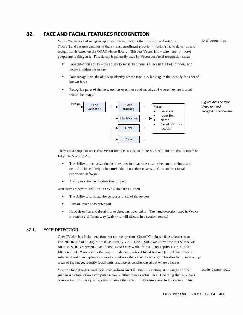
A N K I V E C T O R · 2 0 2 1 . 0 2 . 1 4 316
82. FACE AND FACIAL FEATURES RECOGNITION
Vector “is capable of recognizing human faces, tracking their position and rotation
(“pose”) and assigning names to them via an enrollment process.” Vector’s facial detection and
recognition is based on the OKAO vision library. This lets Vector know when one (or more)
people are looking at it. This library is primarily used by Vector for facial recognition tasks:
Face detection ability – the ability to sense that there is a face in the field of view, and
locate it within the image.
Face recognition, the ability to identify whose face it is, looking up the identify for a set of
known faces
Recognize parts of the face, such as eyes, nose and mouth, and where they are located
within the image.
Face
Detection
Blink
Gaze
Image Face
tracking
Identification
Face
· Location· Identifier· Name· Facial features
location
There are a couple of areas that Vector includes access to in the SDK API, but did not incorporate
fully into Vector’s AI:
The ability to recognize the facial expression: happiness, surprise, anger, sadness and
neutral. This is likely to be unreliable; that is the consensus of research on facial
expression software.
Ability to estimate the direction of gaze
And there are several features in OKAO that are not used
The ability to estimate the gender and age of the person
Human upper body detection
Hand detection and the ability to detect an open palm. The hand detection used in Vector
is done in a different way (which we will discuss in a section below.)
82.1. FACE DETECTION
OpenCV also has facial detection, but not recognition. OpenCV’s classic face detector is an
implementation of an algorithm developed by Viola-Jones. Since we know how that works, we
can discuss it as representative of how OKAO may work. Viola-Jones applies a series of fast
filters (called a “cascade” in the jargon) to detect low-level facial features (called Haar feature
selection) and then applies a series of classifiers (also called a cascade). This divides up interesting
areas of the image, identify facial parts, and makes conclusions about where a face is.
Vector’s face detector (and facial recognition) can’t tell that it is looking at an image of face –
such as a picture, or on a computer screen – rather than an actual face. One thing that Anki was
considering for future products was to move the time of flight sensor next to the camera. This
Anki Cozmo SDK
Figure 82: The face
detection and
recognition processes
Daniel Casner, 2019

A N K I V E C T O R · 2 0 2 1 . 0 2 . 1 4 317
would allow Vector to estimate the size of the face (and its depth variability) but measuring the
distance.
Side note: Anki was exploring ideas (akin to the idea of object permanence) to keep track of a
known person or object in the field of view even when it was too small to be recognized (or
detected).
82.2. FACE IDENTIFICATION AND TRAINING
When it sees a face, it forms a description of the facial features using twelve points:
Each eye has three points,
The nose has two,
The mouth has four points
If you introduce yourself to Vector by voice, you are permitting the robot to associate the name
you provide with Facial Features Data for you. Facial Features Data is stored with the name you
provide, and the robot uses this data to enhance and personalize your experience and do things like
greet you by that name. This data is stored locally on the robot and in the robot’s app. It is not
uploaded to Anki nor shared, and you can delete it anytime.
82.3. COMMUNICATION INTERFACE
There are several commands to manage the faces that Vector recognizes, and to keep informed of
the faces that Vector sees. See Chapter 15 section 56 Faces for more details.
The Enable Face Detection (see Chapter 15 section 56.4 Enable Face Detection) command
enables and disables face detection and analysis stages.
The RobotChangedObservedFaceID and RobotObservedFace (see Chapter 15 section
56.2.4 RobotChangedObservedFaceID and 56.2.6 RobotObservedFace) events are used to
indicate when a face is detected, and tracking it: the identity of the face (if known), where
it is in the field of view, the facial expression, where key parts of the face are (in the view),
etc
The Set Face to Enroll (see Chapter 15 section 56.10 Set Face to Enroll) command is used
to ability assign a name to face, and the Update Enrolled Face By ID (see Chapter 15
section 56.10 Set Face to Enroll) command is used to change the name of a known face
The Request Enrolled Names (see Chapter 15 section 56.9 Request Enrolled Names)
command is used to retrieve a list the known faces
The ability to remove a facial identity (see Chapter 15 section 56.7 Erase Enrolled Face By
Id), or all facial entities (see Chapter 15 section 56.6 Erase All Enrolled Faces)
The Find Faces (see Chapter 15 section 56.8 Find Faces) command initiates the search for
faces
drawing by Jesse
Easley

A N K I V E C T O R · 2 0 2 1 . 0 2 . 1 4 318
83. TENSORFLOW LITE, DETECTING HANDS, PETS… AND THINGS?
Vector includes support to detect hands, and has preliminary support for detecting pets and a wide
variety of objects. These are done using TensorFlow Lite46 (aka TFLite), an inference only neural-
net discriminator.
Detection
objectsImage
Object
· Identifier· Type (hand, pet, etc)· Orientation, scale· Position· Region of image
Object
· Identifier· Type (hand, pet, etc)· Orientation, scale· Position· Region of image
Object
· Identifier· Type (hand, pet, etc)· Orientation, scale· Position· Region of image
Vector’s hand detection is done with a custom TensorFlow Lite DNN model.47 Vector also has a
custom person detector; this may be used to quickly identify whether there is a face in view before
engaging the potentially more expensive OKAO framework.
83.1. DETAILS ON TENSORFLOW LITE
From a distance, the TensorFlow Lite framework acts much the same as a classification trees,
taking inputs, examining properties and producing a result, such as “this is a hand.” Internally
the framework is a designed as a modular virtual machine for signal-processing-like computation.
A “model” is the program for this virtual machine, with information describing its memory
structures, inputs, outputs and the instructions. The analog of a software procedure in the model
are called a graph. The instructions are called operations. Full TensorFlow supports 800+
different operations out of the box, and custom ones can be added. TensoreFlow Lite supports
122+ different operations, and custom ones can be added as well. TensorFlow Lite supports one
graph in a model.
The host application has to do preprocessing such as feature extraction, prepare the input for the
system. For instance, the image must be converted to grey scale and scaled down to 128 pixels by
128 pixels. (More pixels require much more memory and processing steps often with no
improvement in detection; some higher quality models do use slightly larger image sizes.)
Then each of the operations in the model is carried out. An operation might perform a simple
calculation light summing values, keeping the smallest or largest, etc or an operation might be a
complex calculation such as a convolution. Once all of the operations have completed, the results
are not a “this is a hand” or other conventional software result. Instead, the results are big list of
values on how confident it is for each possible item. An application typically chooses the top item
or two as the output – if their confidence is high enough.
46 Since Tensorflow Lite was both introduced at the end of 2017, there has been a steady trickle of improvements to TensorFlow Lite.
There is a lower power version that targets microcontrollers. 47 There are four different hand detector models – only one is used – which suggests that the hand detector was actively being tweaked and improved.
Figure 83: The
processing of the
image for symbols and
objects
Warden & Situnayake,
2019

A N K I V E C T O R · 2 0 2 1 . 0 2 . 1 4 319
TensorFlow Lite includes build time support to replace the key operation implementations with
fast, processor-specific ones:
Delegate(s)
ARM
Neural
Network
framework
Qualcomm
GPU
framework
FlatBuffersTensorflow
Lite
In addition, applications using TensorFlow Lite can provide their own, faster or more efficient
implementations of operations.
Each TensorFlow Lite model is probably run in its own thread. The benchmarks posted by
TensorFlow48 using smartphones to run model tens to hundreds of milliseconds. Putting each
model on its own thread and waiting for posted results allows the rest of the processing to execute
in a consistent fashion.
83.1.1 SalientPoint data structure
The SalientPoint JSON data structure is produced from the neural networks analysis of the image.
These points are used by the behavior system as something interesting to react to as well. The
structure has the following fields:
Field Type Units Description
area_fraction float Area of the region that was identified as a salient
point.
color_rgba uint RGBA How to color this region, for web visualization
description string
salientType string An enumerated type describing the kind of salient
point found.
score float A metric relating how interesting the point/region is
shape array of points?
An array of points outlining the interesting area?
timestamp uint ms The timestamp that this point was identified on
x_img float pixel Pixel coordinate of the upper left hand corner of the
region.
y_img float pixel Pixel coordinate of the upper left hand corner of the
region.
48 https://www.tensorflow.org/lite/performance/benchmarks
Figure 84:
TensorFlow lite with
hardware specific
accelerators
Table 468: SalientPoint
parameters
A N K I V E C T O R · 2 0 2 1 . 0 2 . 1 4 320
83.2. OTHER IDEAS THAT WEREN’T FULLY REALIZED AND FUTURE POTENTIAL
Vector also includes the stock MobileNet V1 (0.5, 128) model to classify images, although it does
not appear to have been used yet. This model was likely intended to give Vector the ability to
identify a wide variety of things, and pets.49
MobileNet V1 includes higher quality models than the one employed that may be explored. Since
this model was released, a version 2 and version 3 of MobileNet have been developed and released.
Version 2 is reported to be faster, higher quality, and/or require fewer processor resources.
(Version 3 is slower and takes more processor resources, but is much more accurate.)
The configuration file shows experimentation with MobileNet V2 (using 192x192 input images),
but it was disabled.
49 Or a special model for recognizing pets may have been under development
drawing by Jesse
Easley
A N K I V E C T O R · 2 0 2 1 . 0 2 . 1 4 321
84. PHOTOS/PICTURES
Vector has the ability to take pictures. The photographs were taken with less than the full camera
resolution. (It isn’t known if Anki intended to eventually take photographs at a higher resolution.)
These pictures are stored on Vector, not in the cloud. The mobile application and SDK
applications can view, delete or share pictures taken by Vector.
The camera/image processing pipeline in Vector is entirely focused on his AI features with as low
as practical battery impact. The images available for taking a picture are not filtered, or cleaned
up, so the pictures that Vector takes are noisy and smaller.
Commentary: The quality of photos seen on a mobile phone is achieved using a camera processing
pipeline to enhance the images, removing noise and applying special filters to reconstruct textures.
It is conceivable that the camera processing framework(s) from Qualcomm and Android could be
added to an open-source Vector. That would come at the cost of battery performance, heat, and
potentially overwhelm the memory resources (there are still bugs in Vector where the memory use
becomes too high, and the system thrashes, slowing noticeably down and eventually crashes.)
It is more practical, in a future open-source Vector, to export the raw camera images (in its RAW
format and at different illumination levels) and process the images on a PC or mobile device. The
availability of sophisticated image processing frameworks are much wider for those devices. See
Chapter 15, section 58 Image Processing for the camera access API.
84.1. COMMUNICATION INTERFACE
There are several commands to manage the photographs that Vector has taken. See Chapter 15
section 65 Photos for more details.
The PhotoTaken event (see Chapter 15 section 65.2.1 PhotoTaken) is used to receive a
notification when Vector has taken a photograph.
The Photos Info (see Chapter 15 section 65.5 Photos Info) command is used to retrieve a
list of the photographs that Vector currently has
The Photo (see Chapter 15 section 65.4 Photo) command is used to retrieve a photo
The Delete Photo command (see Chapter 15 section 65.3 Delete Photo) removes a photo
from the system
The Thumbnail (see Chapter 15 section 65.6 Thumbnail) command retrieves a small
version of the image, suitable for displaying as a thumbnail
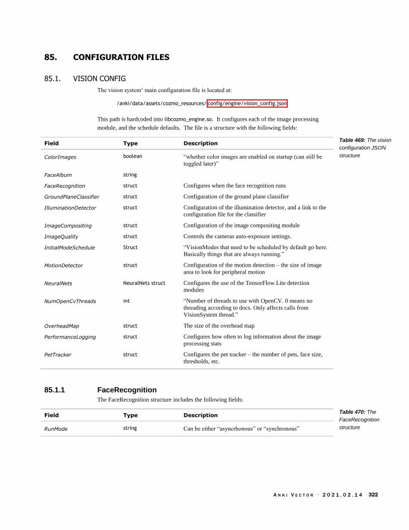
A N K I V E C T O R · 2 0 2 1 . 0 2 . 1 4 322
85. CONFIGURATION FILES
85.1. VISION CONFIG
The vision system’ main configuration file is located at:
/anki/data/assets/cozmo_resources/ config/engine/vision_config.json
This path is hardcoded into libcozmo_engine.so. It configures each of the image processing
module, and the schedule defaults. The file is a structure with the following fields:
Field Type Description
ColorImages boolean “whether color images are enabled on startup (can still be
toggled later)”
FaceAlbum string
FaceRecognition struct Configures when the face recognition runs
GroundPlaneClassifier struct Configuration of the ground plane classifier
IlluminationDetector struct Configuration of the illumination detector, and a link to the
configuration file for the classifier
ImageCompositing struct Configuration of the image compositing module
ImageQuality struct Controls the cameras auto-exposure settings.
InitialModeSchedule Struct “VisionModes that need to be scheduled by default go here.
Basically things that are always running.”
MotionDetector struct Configuration of the motion detection – the size of image
area to look for peripheral motion
NeuralNets NeuralNets struct Configures the use of the TensorFlow Lite detection
modules
NumOpenCvThreads int “Number of threads to use with OpenCV. 0 means no
threading according to docs. Only affects calls from
VisionSystem thread.”
OverheadMap struct The size of the overhead map
PerformanceLogging struct Configures how often to log information about the image
processing stats
PetTracker struct Configures the pet tracker – the number of pets, face size,
thresholds, etc.
85.1.1 FaceRecognition
The FaceRecognition structure includes the following fields:
Field Type Description
RunMode string Can be either “asyncrhonous” or “synchronous”
Table 469: The vision
configuration JSON
structure
Table 470: The
FaceRecognition
structure

A N K I V E C T O R · 2 0 2 1 . 0 2 . 1 4 323
85.1.2 GroundPlaneClassifier
The GroundPlaneClassifier (also called “desk classifier”) is used to visually identify where the
driving surface is. The structure includes the following fields:
Field Type Description
FileOrDirName string Path to the ground plane classifier file.
MaxDepth uint
MinSampleCount uint
OnTheFlyTrain booleab
PositiveWeight float
TruncatePrunedTree boolean
Use1SERule boolean
Note: The Ground Plane classifier is a bit unusual. It is one of only two YAML files. The YAML
file is an openCV based classifier tree, instead of TensorFlow Lite. This suggests it may have been
older (i.e. from Cozmo), and/or it may have been more efficient to implement in openCV.
85.1.3 IlluminationDetector
The IlluminationDetector structure includes the following fields:
Field Type Description
AllowMovement boolean If true, “continue to run even if robot is moving”
ClassifierConfigPath string Path to the illumination classifier configuration file
DarkenedMaxProbability float The “max probability to result in 'Darkened' class”
FeaturePercentileSubsample uint “Stride for building histogram to compute percentiles”
IlluminatedMinProbability float The “min probability to result in 'Illuminated' class”
85.1.4 InitialModeSchedules
The InitialModeSchedules provides the default frequency that each vision processing step is run.
(And step not listed here, the default is that it is not scheduled to run). The structure includes the
following fields:
Field Type Description
AutoExp uint Run the auto exposure step every n frames.
Markers uint Run the markers step every n frames.
WhiteBlance uint Run the white balance step every n frames
Table 471: The
GroundPlaneClassifier
structure
Table 472: The
IlluminationDetector
structure
Table 473: The
InitialModeSchedules
structure

A N K I V E C T O R · 2 0 2 1 . 0 2 . 1 4 324
85.1.5 ImageCompositing
The ImageCompositing The structure includes the following fields:
Field Type Description
imageReadyPeriod uint
numImageReadyCyclesBefo
reReset
uint
percentileForMaxIntensity uint
85.1.6 ImageQuality
The ImageQuality structure includes the following fields:
Field Type Description
CyclingTargetValues float[] “When ‘cycling’ exposure is enabled, the target values to
use.” Each value must be in the range 0 to 255
HighPercentile float Range 0.0 to 1.0
InitialExposureTime_ms uint “Sent each time we request camera calibration”
LowPercentile float Range 0.0 to 1.0
MaxChangeFraction float “Relative amount we can change current exposure/wb each
update, zero disables.” Range: 0.0 to inf
MeterFromDetections boolean “Base auto-exposure on detected markers, faces, etc, if any”
RepeatedErrorMessageInter
val_ms
uint The “time between error messages once triggered”
SubSample uint
TargetPercentile float Range 0.0 to 1.0
TargetValue uint “Try to make targetPercentile have this value.” Range 0 to
254
TimeBeforeErrorMessage_m
s
uint “How long [the] Vision System must detect `bad’ quality
before notifying game”
TooBrightValue uint “‘Too Bright’ if LowPercentile is above this”
TooDarkValue uint “‘Too Dark’ if HighPercentile is below this”
85.1.7 MotionDetector
The MotionDetector structure includes the following fields:
Field Type Description
CentroidStability float “How quickly should peripheral motion detection track the
source of motion.”
DecreaseFactor float “The higher this number, the more quickly motion detection
forgets about motion.”
HorizontalSize float “Fraction of the width of the image to be used for peripheral
motion detection (right and left).”
Table 474: The
ImageCompositing
structure
Table 475: The
ImageQuality structure
Table 476: The
MotionDetector structure

A N K I V E C T O R · 2 0 2 1 . 0 2 . 1 4 325
IncreaseFactor float “The higher this number, the more sensitive is motion
detection to motion.”
MaxValue float “The higher this value, the sooner peripheral motion
detection will be triggered.”
VerticalSize float “Fraction of the height of the image to be used for
peripheral motion detection (top)”
85.1.8 NeuralNets
The NeuralNets structure includes the following fields:
Field Type Description
Models Model[] An array of TensorFlow Lite model configuration structures
(see below).
ProfilingEventLogFrequency
_ms
uint How often to log information about the model execution
timing.
ProfilingPrintFrequency_ms uint How often to print (to TBD) information about the model
execution timing.
Table 477: The
NeuralNets structure

A N K I V E C T O R · 2 0 2 1 . 0 2 . 1 4 326
The Models is an array of structures. Each structure has the following fields:
Field Type Description
architecture string
benchmarkRuns uint If non-zero, gather duration and resource usage information
for each run.
graphFile string The name of the TensorFlow Lite file (.tflite) to load to
implement this model
inputHeight uint The height, in pixels, of the input image. Typically 128
inputLayerName string The name of the input layer in the TensorFlow Lite file.
inputWidth uint The width, in pixels, of the input image. Typically 128
inputScale float When the input data type is “float”, the data is first scaled
by this number, then the shift value is added:
float_input = data / inputScale + inputShift
inputShift int
labelsFile string The name of the text file (.txt) that gives text strings for the
classification output of the model.
memoryMapGraph uint ?If non-zero, memory-map the TensorFlow Lite file in,
rather than loading it with file reads.
minScore float If the highest “score” for a label is below this value, none of
the items was recognized in the image.
modelType string “TFLite” for TensorFlow Lite files.
networkName string The name of the vision processing step.
numGridCols uint Optional.
numGridRows uint Optional.
outputLayerNames string The name of the output layer in the TensorFlow Lite file.
outputType string “classification” vs “binary_localization”
pollPeriod_ms uint
timeoutDuration_sec float ?The time to allow the model to run in a background thread
without any results before it is considered timed out, and
must be restarted?
useFloatInput uint If non-zero, use float data type within the model
useGrayscale uint
verbose uint If non-zero, provide verbose output during the interpretation
of the model.
TENSORFLOW MODEL FILES
The TensorFlow Lite models are stored in:
/anki/data/assets/cozmo_resources/config/engine/ dnn_models
The last part of the path is hardcoded into libcozmo_engine.so.
Table 478: The
TensorFlow Lite model
configuration structure
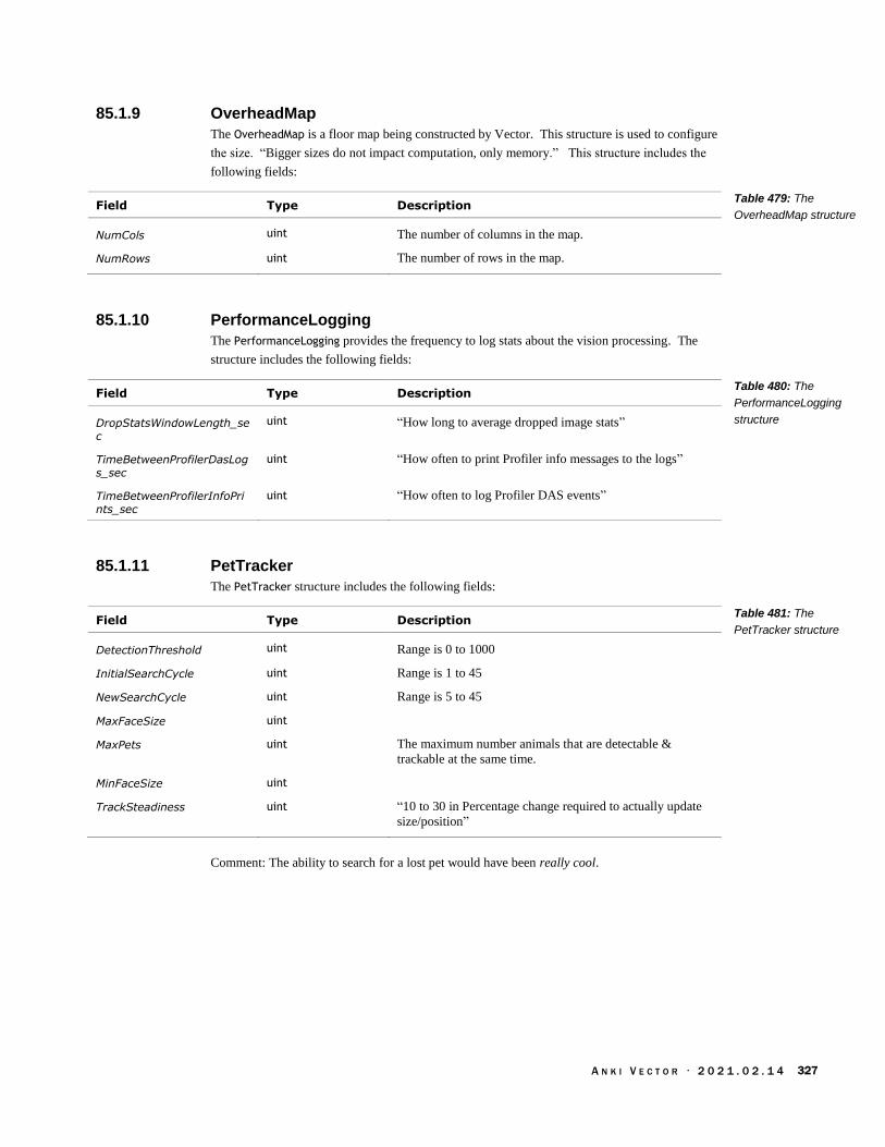
A N K I V E C T O R · 2 0 2 1 . 0 2 . 1 4 327
85.1.9 OverheadMap
The OverheadMap is a floor map being constructed by Vector. This structure is used to configure
the size. “Bigger sizes do not impact computation, only memory.” This structure includes the
following fields:
Field Type Description
NumCols uint The number of columns in the map.
NumRows uint The number of rows in the map.
85.1.10 PerformanceLogging
The PerformanceLogging provides the frequency to log stats about the vision processing. The
structure includes the following fields:
Field Type Description
DropStatsWindowLength_sec
uint “How long to average dropped image stats”
TimeBetweenProfilerDasLogs_sec
uint “How often to print Profiler info messages to the logs”
TimeBetweenProfilerInfoPrints_sec
uint “How often to log Profiler DAS events”
85.1.11 PetTracker
The PetTracker structure includes the following fields:
Field Type Description
DetectionThreshold uint Range is 0 to 1000
InitialSearchCycle uint Range is 1 to 45
NewSearchCycle uint Range is 5 to 45
MaxFaceSize uint
MaxPets uint The maximum number animals that are detectable &
trackable at the same time.
MinFaceSize uint
TrackSteadiness uint “10 to 30 in Percentage change required to actually update
size/position”
Comment: The ability to search for a lost pet would have been really cool.
Table 479: The
OverheadMap structure
Table 480: The
PerformanceLogging
structure
Table 481: The
PetTracker structure

A N K I V E C T O R · 2 0 2 1 . 0 2 . 1 4 328
85.2. SCHEDULE MEDIATOR CONFIGURATION FILES
The scheduling for the different vision system modules – how often each processing step is run – is
configuration in file located at:
/anki/data/assets/cozmo_resources/ config/engine/visionScheduleMediator_config.json
This path is also hardcoded into libcozmo_engine.so.
This is an array of structures. Each structure gives the frequency to run a given image processing
step, for each of the vision processing subsystems modes. 1 means “runs every frame,” 4 every
fourth frame, and so on. The structure has the following fields:
Field Type Description
high uint When in high “mode” run the image processing step every n
frames. This value must be a power of two.
low uint When in low “mode” run the image processing step every n
frames. This value must be a power of two.
med uint When in medium “mode” run the image processing step
every n frames. This value must be a power of two.
mode string The name of the image processing step
relativeCost uint A “heuristic weighting to drive separation of heavy-weight
tasks between frames where 1 should indicate our lowest
cost process e.g. “Markers” is ~16x as resource intensive as
“CheckingQuality”
standard uint When in medium “mode” run the image processing step
every n frames. This value must be a power of two.
85.3. PHOTOGRAPHY CONFIGURATION FILES
The photography subsystem configuration in file located at:
/anki/data/assets/cozmo_resources/ config/engine/photography_config.json
This path is also hardcoded into libcozmo_engine.so.
This is structure has the following fields:
Field Type Description
MaxSlots uint
MedianFilterSize uint “If > 0, enables a median filter before saving. Must be odd.
3 or 5 are reasonable values.”
SharpeningAmount float 0.0 disables sharpening
RemoveDistortion boolean
SaveQuality uint
ThumbnailScale float
Table 482: The vision
schedule configuration
JSON structure
Table 483: The
photography
configuration JSON file

A N K I V E C T O R · 2 0 2 1 . 0 2 . 1 4 329
86. RESOURCES & RESOURCES
ARM, Neural-network Machine learning software repo
https://github.com/ARM-software/armnn
Barrett, L. F., Adolphs, R., Marsella, S., Martinez, A. M., & Pollak, S. D. Emotional expressions
reconsidered: Challenges to inferring emotion from human facial movements. Psychological
Science in the Public Interest, 20, 1–68. (2019). doi:10.1177/1529100619832930
https://journals.sagepub.com/stoken/default+domain/10.1177%2F1529100619832930-
FREE/pdf
This paper describes the limitations and high error rate of facial expression software.
FloydHub, Teaching My Robot With TensorFlow, 2018 Jan 24,
https://blog.floydhub.com/teaching-my-robot-with-tensorflow/
Google, MobileNets: Open-Source Models for Efficient On-Device Vision, 2017, Jun 14,
https://ai.googleblog.com/2017/06/mobilenets-open-source-models-for.html
Hollemans, Matthijs. Google’s MobileNets on the iPhone, 2017 Jun 14
https://machinethink.net/blog/googles-mobile-net-architecture-on-iphone/
MobileNet version 2, 2018 Apr 22
https://machinethink.net/blog/mobilenet-v2/
These two blog posts give an excellent overview of the mechanics of the MobileNet
architecture.
Omron, Human Vision Component (HVC-P2) B5T-007001 Evaluation Software Manual, 2016
http://www.farnell.com/datasheets/2553338.pdf
Omron, OKAO Vision Software Library
https://www.components.omron.com/sensors/image-sensing/solution/software-library
Qualcomm, How can Snapdragon 845’s new AI boost your smartphone’s IQ?, 2018 Feb 1
https://www.qualcomm.com/news/onq/2018/02/01/how-can-snapdragon-845s-new-ai-boost-
your-smartphones-iq
Qualcomm, Snapdragon Neural Processing Engine SDK Reference Guide,
https://developer.qualcomm.com/docs/snpe/overview.html
Qualcomm Neural Processing software development kit (SDK) for advanced on-device AI,
the Qualcomm Computer Vision Suite
Situnayake, Daniel; Pete Warden, TinyML, O’Reilly Media, Inc. 2019 Dec,
https://www.oreilly.com/library/view/tinyml/9781492052036/
Stein, Andrew; Decoding Machine-Readable Optical codes with Aesthetic Component, Anki,
Patent US 9,607,199 B2, 2017 Mar. 28
TensorFlow, Mobile Net v1
https://github.com/tensorflow/models/blob/master/research/slim/nets/mobilenet_v1.md
“small, low-latency, low-power models” that can recognize a variety of objects (including
animals) in images, while running on a microcontroller
TensorFlow, TensorFlow Lite GPU delegate
https://www.tensorflow.org/lite/performance/gpu
TensorFlow, TensorFlow Lite inference
https://www.tensorflow.org/lite/guide/inference
This Week in Machine Learning (TWIMLAI), episode 102, Computer Vision for Cozmo, the
Cutest Toy Robot Everrrrr! with Andrew Stein
https://twimlai.com/twiml-talk-102-computer-vision-cozmo-cutest-toy-robot-everrrrr-andrew-
stein/

A N K I V E C T O R · 2 0 2 1 . 0 2 . 1 4 330
Viola, Paul; Michael Jones, Rapid Object Detection using a Boosted Cascade of Simple Features,
Accepted Conference on Computer Vision and Patter Recognition, 2001
http://wearables.cc.gatech.edu/paper_of_week/viola01rapid.pdf
Wikipedia, Adaptive histogram equalization
https://en.wikipedia.org/wiki/Adaptive_histogram_equalization
Wikipedia, Viola-Jones object detection framework
https://en.wikipedia.org/wiki/Viola%E2%80%93Jones_object_detection_framework
Viola, Paul; Michael Jones, Robust Real-time Object Detection, International Journal of Computer
Vision (2001)
http://citeseerx.ist.psu.edu/viewdoc/summary?doi=10.1.1.110.4868
Example code for running a TensorFlow Lite model on a PC
https://github.com/ctuning/ck-tensorflow/blob/master/program/object-detection-
tflite/detect.cpp

A N K I V E C T O R · 2 0 2 1 . 0 2 . 1 4 331
CHAPTER 20
Mapping & Navigation
Vector builds an internal map to track where he can drive, where objects and faces are.
Mapping Overview
Navigation and Path Planning
87. MAPPING OVERVIEW
Vector tracks objects in two domains:
Objects track in
camera image
coordinates
2D surface map
A 2D map that is used to track where objects (especially objects whose marker symbols he
recognizes), cliffs, and other things are on the surfaces that he can drive on. Vector uses
this map to navigate. This map has an arbitrary origin and orientation.
Vector also tracks where faces, pets and some kinds of recognized objects are in his
camera image area; these objects are tracked in the image pixels. (Never mind that the
camera pose can change!)
Vector’s 2-D surface map system works with the localization and navigation subsystem. It uses
several sensors to know
Cliff sensors to detect edge, and lines
Time of flight sensor to measure distances
Vision to detect the edges, and the location of a hand
Vision to identify accessories by recognizing markers
88. MAP REPRESENTATION
Vector keeps tracks of the surface that he can drive on with a navigable 2D map. The map’s
orientation and position of its origin are arbitrary – Vector just picks a spot and goes with it. The
surface map is represented in a compressed format called a quad-tree.
Figure 85: Mapping
contexts

A N K I V E C T O R · 2 0 2 1 . 0 2 . 1 4 332
Vector tracks accessory objects, immovable obstacles, and cliffs in terms of this map. The map’s
units are in mm.
88.1. QUAD-TREE MAP REPRESENTATION BASICS
A quad-tree is a structured way of “compressing” the information in the map, to reduce the
amount of memory required. A quad-tree that recursively breaks down a grid into areas that are
interesting, and those that are note.
Leaf node (quad),
level 2
Root node
Leaf node (quad),
level 1
Inner node
The tree has two kinds of nodes: inner nodes and leaf nodes:
The inner nodes do not hold any information about the region (except its size). Instead
they point to 4 child nodes at the next lower layer. The top most node is called the root
node.
The leaf nodes of the tree are square cells (called quads) that hold information about what
is there (or that the area is unexplored).
Each node represents a square area. The size of the square depends on how many levels it is from
the root node. The root node covers the whole map. The nodes in the next layer down are half the
width and height of the root node. (In general, a node is half the width and height of a node the
next layer up.) Nodes (including quads) at the same level – the same distance from the root node –
are the same size. Each node’s coordinates can be figured in a similar way by knowing the
coordinates of the root node.
When Vector reaches the edge of his map area and needs to expand it, he has to add a new node at
the top (this becomes the new root node) and adds nodes down until it can contain the info at the
edge of the map.
88.2. THE MAP’S STARTING POINT
Vector doesn’t have a “north pole” or other global reference point to center his map on. When he
powers on, or “whenever Vector is delocalized (i.e. whenever Vector no longer knows where he
is – e.g. when he's picked up), Vector creates a new pose starting at (0,0,0) with no rotation. As
Vector drives around, his pose (and the pose of other objects he observes – e.g. faces, his [cube],
charger, etc.) is relative to this initial position and orientation.”
Client applications (the ones that talk via the HTTPS API) may also wish to know that the map was
thrown out and a new one created – and thus know they should toss out their map and location of
objects. Vector associates a unique identifier with each generation of the map called origin_id.
Whenever a new map is created the “origin_id [is] incremented to show that [the] poses [of the
quad-tree
Figure 86: Structure
of a quad-tree
Anki SDK
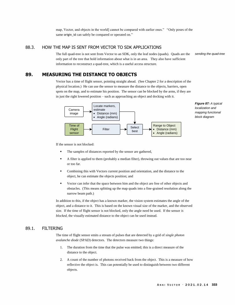
A N K I V E C T O R · 2 0 2 1 . 0 2 . 1 4 333
map, Vector, and objects in the world] cannot be compared with earlier ones.” “Only poses of the
same origin_id can safely be compared or operated on.”
88.3. HOW THE MAP IS SENT FROM VECTOR TO SDK APPLICATIONS
The full quad-tree is not sent from Vector to an SDK, only the leaf nodes (quads). Quads are the
only part of the tree that hold information about what is in an area. They also have sufficient
information to reconstruct a quad-tree, which is a useful access structure.
89. MEASURING THE DISTANCE TO OBJECTS
Vector has a time of flight sensor, pointing straight ahead. (See Chapter 2 for a description of the
physical location.) He can use the sensor to measure the distance to the objects, barriers, open
spots on the map, and to estimate his position. The sensor can be blocked by the arms, if they are
in just the right lowered position – such as approaching an object and docking with it.
Range to Object
· Distance (mm)
· Angle (radians)
Filter
Locate markers,
estimate
· Distance (mm)
· Angle (radians)
Time of
Flight
sensor
Camera
image
Select
best
If the sensor is not blocked:
The samples of distances reported by the sensor are gathered,
A filter is applied to them (probably a median filter), throwing out values that are too near
or too far.
Combining this with Vectors current position and orientation, and the distance to the
object, he can estimate the objects position; and
Vector can infer that the space between him and the object are free of other objects and
obstacles. (This means splitting up the map quads into a fine-grained resolution along the
narrow beam path.)
In addition to this, if the object has a known marker, the vision system estimates the angle of the
object, and a distance to it. This is based on the known visual size of the marker, and the observed
size. If the time of flight sensor is not blocked, only the angle need be used. If the sensor is
blocked, the visually estimated distance to the object can be used instead.
89.1. FILTERING
The time of flight sensor emits a stream of pulses that are detected by a grid of single photon
avalanche diode (SPAD) detectors. The detectors measure two things:
1. The duration from the time that the pulse was emitted; this is a direct measure of the
distance to the object.
2. A count of the number of photons received back from the object. This is a measure of how
reflective the object is. This can potentially be used to distinguish between two different
objects.
sending the quad-tree
Figure 87: A typical
localization and
mapping functional
block diagram
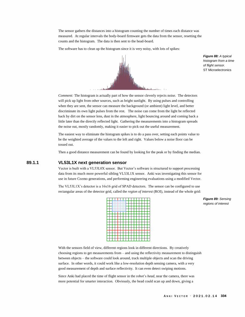
A N K I V E C T O R · 2 0 2 1 . 0 2 . 1 4 334
The sensor gathers the distances into a histogram counting the number of times each distance was
measured. At regular intervals the body-board firmware gets the data from the sensor, resetting the
counts and the histogram. The data is then sent to the head-board.
The software has to clean up the histogram since it is very noisy, with lots of spikes:
Comment: The histogram is actually part of how the sensor cleverly rejects noise. The detectors
will pick up light from other sources, such as bright sunlight. By using pulses and controlling
when they are sent, the sensor can measure the background (or ambient) light level, and better
discriminate its own light pulses from the rest. The noise can come from the light be reflected
back by dirt on the sensor lens, dust in the atmosphere, light bouncing around and coming back a
little later than the directly reflected light. Gathering the measurements into a histogram spreads
the noise out, mostly randomly, making it easier to pick out the useful measurement.
The easiest way to eliminate the histogram spikes is to do a pass over, setting each points value to
be the weighted average of the values to the left and right. Values below a noise floor can be
tossed out.
Then a good distance measurement can be found by looking for the peak or by finding the median.
89.1.1 VL53L1X next generation sensor
Vector is built with a VL53L0X sensor. But Vector’s software is structured to support processing
data from its much more powerful sibling VL53L1X sensor. Anki was investigating this sensor for
use in future Cozmo generations, and performing engineering evaluations using a modified Vector.
The VL53L1X’s detector is a 16x16 grid of SPAD detectors. The sensor can be configured to use
rectangular areas of the detector grid, called the region of interest (ROI), instead of the whole grid:
With the sensors field of view, different regions look in different directions. By creatively
choosing regions to get measurements from – and using the reflectivity measurement to distinguish
between objects – the software could look around, track multiple objects and scan the driving
surface. In other words, it could work like a low-resolution depth sensing camera, with a very
good measurement of depth and surface reflectivity. It can even detect swiping motions.
Since Anki had placed the time of flight sensor in the robot’s head, near the camera, there was
more potential for smarter interaction. Obviously, the head could scan up and down, giving a
Figure 88: A typical
histogram from a time
of flight sensor.
ST Microelectronics
Figure 89: Sensing
regions of interest
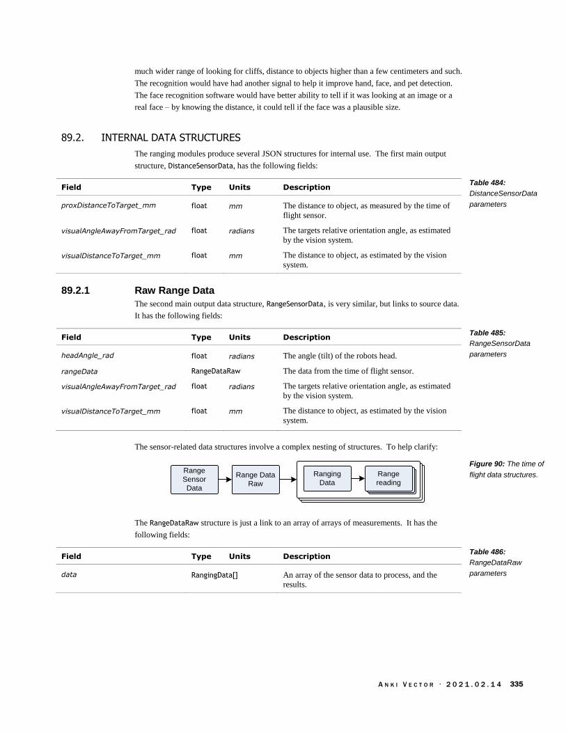
A N K I V E C T O R · 2 0 2 1 . 0 2 . 1 4 335
much wider range of looking for cliffs, distance to objects higher than a few centimeters and such.
The recognition would have had another signal to help it improve hand, face, and pet detection.
The face recognition software would have better ability to tell if it was looking at an image or a
real face – by knowing the distance, it could tell if the face was a plausible size.
89.2. INTERNAL DATA STRUCTURES
The ranging modules produce several JSON structures for internal use. The first main output
structure, DistanceSensorData, has the following fields:
Field Type Units Description
proxDistanceToTarget_mm float mm The distance to object, as measured by the time of
flight sensor.
visualAngleAwayFromTarget_rad float radians The targets relative orientation angle, as estimated
by the vision system.
visualDistanceToTarget_mm float mm The distance to object, as estimated by the vision
system.
89.2.1 Raw Range Data
The second main output data structure, RangeSensorData, is very similar, but links to source data.
It has the following fields:
Field Type Units Description
headAngle_rad float radians The angle (tilt) of the robots head.
rangeData RangeDataRaw The data from the time of flight sensor.
visualAngleAwayFromTarget_rad float radians The targets relative orientation angle, as estimated
by the vision system.
visualDistanceToTarget_mm float mm The distance to object, as estimated by the vision
system.
The sensor-related data structures involve a complex nesting of structures. To help clarify:
Range Data
Raw
Range
Sensor
Data
Ranging
DataRange
reading
Range
reading
Range
reading
The RangeDataRaw structure is just a link to an array of arrays of measurements. It has the
following fields:
Field Type Units Description
data RangingData[] An array of the sensor data to process, and the
results.
Table 484:
DistanceSensorData
parameters
Table 485:
RangeSensorData
parameters
Figure 90: The time of
flight data structures.
Table 486:
RangeDataRaw
parameters

A N K I V E C T O R · 2 0 2 1 . 0 2 . 1 4 336
The RangingData structure has the following fields:
Field Type Units Description
numObjects uint count A count of the number of objects seen in the
regions.
processedRange_mm int mm The range to the object after processing & filtering
of the data
readings RangeReading[] The range readings reported from the time of flight
sensor
roi uint The region of interest that was measured.
roiStatus uint A code indicating whether there is a valid
measurement for this region.
spadCount float “the time difference (shift) between the reference
and return [detector] arrays.” This translates to
distance to the target.
The RangeReading structure is basically identical to the structure in ST’s software to interface with
the time of flight sensor. It has the following fields:
Field Type Units Description
ambientRate_mcps float mcps The ambient number of counts; this is the noise
floor
rawRange_mm int mm
sigma_mm float mm The distance to the target
signalRate_mcps float mcps The “return signal rate measurement… represents
the amplitude of the signal reflected from the target
and detected by the device.”
status uint A code with 0 indicating a valid measurement,
otherwise indicating an error during measurement
or processing.
Note: mcps is mega counts per second.
89.2.2 Display-Ready Range Data
The RangeDataDisplay structure is just a link to an array of arrays of measurements. It has the
following fields:
Field Type Units Description
data RangingDataDisplay[] The ranging data, for potential display.
Table 487: RangingData
parameters
Table 488:
RangeReading
parameters
Table 489:
RangeDataDisplay
parameters
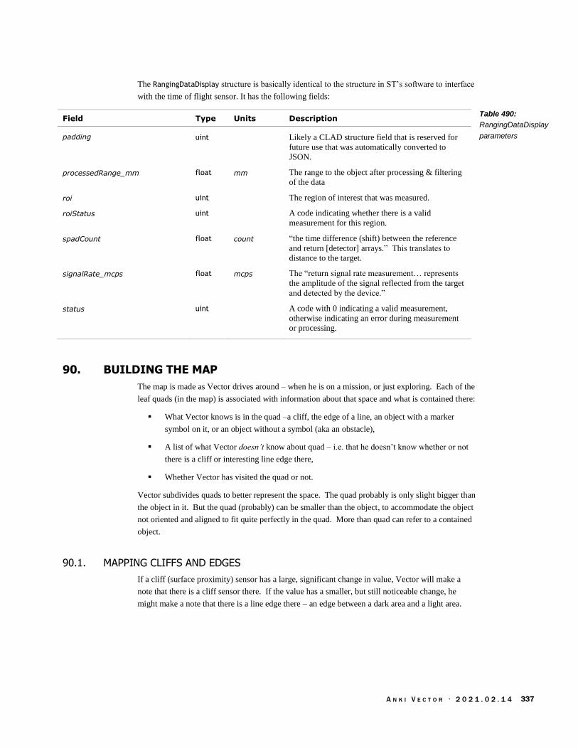
A N K I V E C T O R · 2 0 2 1 . 0 2 . 1 4 337
The RangingDataDisplay structure is basically identical to the structure in ST’s software to interface
with the time of flight sensor. It has the following fields:
Field Type Units Description
padding uint Likely a CLAD structure field that is reserved for
future use that was automatically converted to
JSON.
processedRange_mm float mm The range to the object after processing & filtering
of the data
roi uint The region of interest that was measured.
roiStatus uint A code indicating whether there is a valid
measurement for this region.
spadCount float count “the time difference (shift) between the reference
and return [detector] arrays.” This translates to
distance to the target.
signalRate_mcps float mcps The “return signal rate measurement… represents
the amplitude of the signal reflected from the target
and detected by the device.”
status uint A code with 0 indicating a valid measurement,
otherwise indicating an error during measurement
or processing.
90. BUILDING THE MAP
The map is made as Vector drives around – when he is on a mission, or just exploring. Each of the
leaf quads (in the map) is associated with information about that space and what is contained there:
What Vector knows is in the quad –a cliff, the edge of a line, an object with a marker
symbol on it, or an object without a symbol (aka an obstacle),
A list of what Vector doesn’t know about quad – i.e. that he doesn’t know whether or not
there is a cliff or interesting line edge there,
Whether Vector has visited the quad or not.
Vector subdivides quads to better represent the space. The quad probably is only slight bigger than
the object in it. But the quad (probably) can be smaller than the object, to accommodate the object
not oriented and aligned to fit quite perfectly in the quad. More than quad can refer to a contained
object.
90.1. MAPPING CLIFFS AND EDGES
If a cliff (surface proximity) sensor has a large, significant change in value, Vector will make a
note that there is a cliff sensor there. If the value has a smaller, but still noticeable change, he
might make a note that there is a line edge there – an edge between a dark area and a light area.
Table 490:
RangingDataDisplay
parameters

A N K I V E C T O R · 2 0 2 1 . 0 2 . 1 4 338
90.2. TRACKING OBJECTS
Vector tracks objects (especially objects with markers) using the map, and other cross-referencing
structures. Vector associates the following information with each object it tracks:
The object’s kind (dock, cube, etc)
A pose. The image skew of the marker symbol gives some partial attitude (relative
orientation) information about the object and Vector can compute an estimated orientation
(relative to the coordinate system) of the object from this and Vector’s own pose. Vector
can estimate the objects position from his own position, orientation, and the distance
measured by the time of flight sensor.
A size of the object. Vector is told the size of objects with the given symbol.
A link to a control structure for the kind of object. For instance, accessory cubes can be
blinked and sensed.
If he sees a symbol, he uses the objects known size, the image scale, its pose (if known) and any
time-of-flight information to (a) refine his estimated location on the map, (b) update the location
and orientation of that object.
90.3. BUILDING A MAP WITH SLAM
Vector employs a mapping technique known as simultaneous location and mapping (SLAM) to
integrate these (and other) steps. SLAM is a method to identify Vector’s current position and
orientation (relative to the map), and to construct that map.
Build Map
Enhanced
Kalman Filter
Filter
Apply current
position,
orientation
Odometry
Feature
extraction
Position & angle
Time of
Flight
sensor
Camera
image
IMU
Identify markers
· Distance (mm)
· Angle (radians)
Select
best
SLAM consists of multiple parts. It integrates the sensor for distance and movement. It also uses
image processing to figure it out where it is at. It identifies landmarks, and information about
them. In a sophisticated integration process, it can estimate Vector’s orientation and if an object
has moved. The estimate of Vectors orientation is based on turn information from the IMU, and
refined by what it can see.
Figure 91: A typical
localization and
mapping functional
block diagram

A N K I V E C T O R · 2 0 2 1 . 0 2 . 1 4 339
91. NAVIGATION AND PLANNING
Path planning is devising a path around obstacles without collision, to accomplish some goal, such
as docking with the “home” (charger) or accessory cube. Intuitively, all you need to with a
rectilinear grid is to figuring out the x-y points to go from point A to B. Vector (and Cozmo) is
longer than they are wide – especially when carrying a cube. If this isn’t taken into account by the
planner, Vector could get stuck going down some path he can’t fit in or turn around in. Cozmo had
an XY-theta planner to construct paths that he could traverse.
Vector’s path planning approach is unknown.
92. RESOURCES & RESOURCES
Riisgaard, Søren; Morten Rufus Blas; SLAM for Dummies: A Tutorial Approach to Simultaneous
Localization and Mapping
http://www-inst.eecs.berkeley.edu/~ee290t/fa18/readings/Slam-for-dummies-mit-tutorial.pdf
ST Microelectronics, UM2039 World smallest Time-of-Flight ranging and gesture detection sensor
Application Programming Interface, Rev, 2016 Jun
https://www.st.com/resource/en/user_manual/dm00279088-world-smallest-timeofflight-
ranging-and-gesture-detection-sensor-application-programming-interface-
stmicroelectronics.pdf
ST Microelectronics, UM2600 Counting people with the VL53L1X long-distance ranging Time-of-
Flight sensor, Rev 1, 2019 Jun
https://www.st.com/resource/en/user_manual/dm00626942-counting-people-with-the-
vl53l1x-longdistance-ranging-timeofflight-sensor-stmicroelectronics.pdf
Wikipedia, Occupancy grid mapping,
https://en.wikipedia.org/wiki/Occupancy_grid_mapping
Vector’s map is based on occupancy grids, except it does not use probabilities.
A N K I V E C T O R · 2 0 2 1 . 0 2 . 1 4 340
CHAPTER 21
Accessories
Vector’s accessories include his charging station, companion cube, and custom items that can be
defined thru the SDK.
Accessories in general: symbols, docking
Home & Charging Station
Companion cube, which is “smart,” sensing movement, orientation, taps being held and is
able to provide feedback via lights
Custom items
93. ACCESSORIES IN GENERAL
Accessories have at least one maker symbol that Vector can recognize. Vector tracks the location
and orientation based on this.
93.1. DOCKING
Docking is a behaviour/action that is used for both approaching the cube, charging station (home),
and other marked items.
It has specialized steps depending on whether it is a cube, the home, etc.
94. HOME & CHARGING STATION
Vector has a rich set of behaviours associated with its Home / Charger. In retrospect, this makes
sense, as it is Vectors home, his nest, his comfy chair.
94.1. DOCKING
Vector’s step in docking with the charging station are:
1. Approach and line up with the charger
2. Turn around (rotate 180°)
3. Reverse and back up the ramp. Vector uses a line follower, with his cliff sensors, to drive
straight backwards. (Since he is going backwards, he can’t use vision.) He uses the tilt of
the ramp to confirm that he is on the charger
4. He also checks that he is in the right spot by looking for power to his charging pads, as
reported by body-board charging circuit. If he is unable to find the spot, he grumbles about
it, drives off and retries.
Vector has a cute low light mode that turns on most of the pixels on his display to see a bit more,
and locate his home.

A N K I V E C T O R · 2 0 2 1 . 0 2 . 1 4 341
95. COMPANION CUBE
Vector has a companion cube that he can pickup, illuminate the lights on, and detect taps. The
cubes design is described in chapter 5.
Vector can roll his cube, shove it around, use it to “pop a wheelie,” and pick it up. To do these, he
must line up squarely with cube. Vision was found to be needed in the Cozmo to align precisely
enough to get the lift hooks into the cube.
95.1. COMMUNICATION
Vector connects with the cube via Bluetooth LE. This communication link provides the ability for
Vector to:
Discover cubes
Pair with a cube (note that Vector can pair with only one cube, and if he is not already
paired, he will automatically pair with the first cube he receives Bluetooth LE advertising
for.)
Check the firmware version
Update the cube firmware
Check the cube’s battery level
Detect the cube orientation
Detect taps on the cube
Turn the cubes lights on and off.
The HTTPS API provides the following Cube-related commands:
List the available cubes, see Chapter 15, section 53.4 Cubes Available
Forget (or unpair) from his preferred cube, see Chapter 15, section 53.8 Forget Preferred
Cube
Pair to the first cube detected, see Chapter 15, section 53.15 Set Preferred Cube
Connect to his cube , see Chapter 15, section 53.3 Connect Cube
Disconnect from the cube, see Chapter 15, section 53.5 Disconnect Cube
Dock with his cube, see Chapter 15, section 53.6 Dock With Cube
Flash cube lights, see Chapter 15, section 53.7 Flash Cube Lights and 53.14 Set Cube
Lights. The later allows using a complex pattern
Pick up an object (his cube), see Chapter 15, section 53.9 Pickup Object
Place his object (his cube) on the ground, see Chapter 15, section 53.10 Place Object on
Ground Here
Pop a wheelie, see Chapter 15, section 53.11 Pop A Wheelie
Roll his cube, see Chapter 15, section 53.12 Roll Block and 53.13 Roll Object
The state of the cube is reported to the HTTPS API.
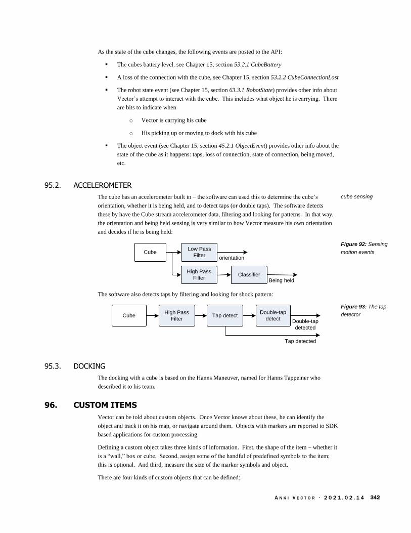
A N K I V E C T O R · 2 0 2 1 . 0 2 . 1 4 342
As the state of the cube changes, the following events are posted to the API:
The cubes battery level, see Chapter 15, section 53.2.1 CubeBattery
A loss of the connection with the cube, see Chapter 15, section 53.2.2 CubeConnectionLost
The robot state event (see Chapter 15, section 63.3.1 RobotState) provides other info about
Vector’s attempt to interact with the cube. This includes what object he is carrying. There
are bits to indicate when
o Vector is carrying his cube
o His picking up or moving to dock with his cube
The object event (see Chapter 15, section 45.2.1 ObjectEvent) provides other info about the
state of the cube as it happens: taps, loss of connection, state of connection, being moved,
etc.
95.2. ACCELEROMETER
The cube has an accelerometer built in – the software can used this to determine the cube’s
orientation, whether it is being held, and to detect taps (or double taps). The software detects
these by have the Cube stream accelerometer data, filtering and looking for patterns. In that way,
the orientation and being held sensing is very similar to how Vector measure his own orientation
and decides if he is being held:
CubeLow Pass
Filter
Classifier
orientation
High Pass
Filter Being held
The software also detects taps by filtering and looking for shock pattern:
CubeHigh Pass
FilterTap detect
Double-tap
detectDouble-tap
detected
Tap detected
95.3. DOCKING
The docking with a cube is based on the Hanns Maneuver, named for Hanns Tappeiner who
described it to his team.
96. CUSTOM ITEMS
Vector can be told about custom objects. Once Vector knows about these, he can identify the
object and track it on his map, or navigate around them. Objects with markers are reported to SDK
based applications for custom processing.
Defining a custom object takes three kinds of information. First, the shape of the item – whether it
is a “wall,” box or cube. Second, assign some of the handful of predefined symbols to the item;
this is optional. And third, measure the size of the marker symbols and object.
There are four kinds of custom objects that can be defined:
cube sensing
Figure 92: Sensing
motion events
Figure 93: The tap
detector

A N K I V E C T O R · 2 0 2 1 . 0 2 . 1 4 343
A fixed, unmarked cube-shaped object.
A flat wall with only a front side,
A cube, with the same marker on each side.
A box with different markers on each side.
96.1. A FIXED, UNMARKED OBJECT (CUBE-SHAPED)
The object is in a fixed position and orientation. This cube can’t be observed since it is unmarked.
So there won’t be any events related to this object. “This could be used to make Vector aware of
objects and know to plot a path around them.”
96.2. CUSTOM WALL DEFINITION
The second type of custom object is a wall. It has a single marker on the front face.
ma
rke
r h
eig
ht
(mm
)
he
igh
t (m
m)
10 m
m
marker width (mm)
width (mm)
Center
The marker must be horizontally and vertically centered. The width of the marker doesn’t have to
be the same as the height… but probably should be.
The body origin is the 5mm behind the center of the face. When Vector is tracking the position
and orientation of this object, the position it gives for the point in the wall 5mm behind the face, at
half the height and width – the center of the wall.
Figure 94: The
custom wall
parameters

A N K I V E C T O R · 2 0 2 1 . 0 2 . 1 4 344
96.3. CUSTOM CUBE DEFINITION
The third type of custom object is a cube. A cube’s width, height and depth are all the same size.
A cube has the same marker on all 6 faces (not shown below):
siz
e (
mm
)
size
(mm
)
size (mm)
marker width (mm)
ma
rke
r h
eig
ht
(mm
)
The marker must be horizontally and vertically centered on each face. The width of the marker
doesn’t have to be the same as the height… but probably should be.
The body origin is the very center of the cube. When Vector is tracking the position and
orientation of this object, the position it gives is for the very center of the cube, not for a visible
face.
Figure 95: The
custom cube
parameters
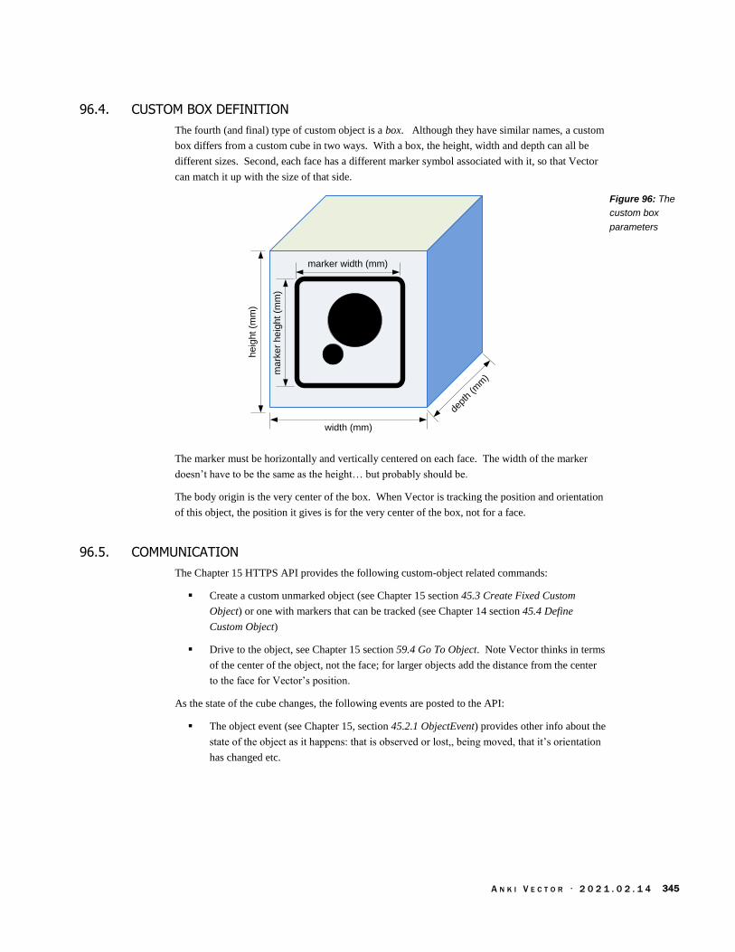
A N K I V E C T O R · 2 0 2 1 . 0 2 . 1 4 345
96.4. CUSTOM BOX DEFINITION
The fourth (and final) type of custom object is a box. Although they have similar names, a custom
box differs from a custom cube in two ways. With a box, the height, width and depth can all be
different sizes. Second, each face has a different marker symbol associated with it, so that Vector
can match it up with the size of that side.
he
igh
t (m
m)
dept
h (m
m)
width (mm)
marker width (mm)
ma
rke
r h
eig
ht
(mm
)
The marker must be horizontally and vertically centered on each face. The width of the marker
doesn’t have to be the same as the height… but probably should be.
The body origin is the very center of the box. When Vector is tracking the position and orientation
of this object, the position it gives is for the very center of the box, not for a face.
96.5. COMMUNICATION
The Chapter 15 HTTPS API provides the following custom-object related commands:
Create a custom unmarked object (see Chapter 15 section 45.3 Create Fixed Custom
Object) or one with markers that can be tracked (see Chapter 14 section 45.4 Define
Custom Object)
Drive to the object, see Chapter 15 section 59.4 Go To Object. Note Vector thinks in terms
of the center of the object, not the face; for larger objects add the distance from the center
to the face for Vector’s position.
As the state of the cube changes, the following events are posted to the API:
The object event (see Chapter 15, section 45.2.1 ObjectEvent) provides other info about the
state of the object as it happens: that is observed or lost,, being moved, that it’s orientation
has changed etc.
Figure 96: The
custom box
parameters

A N K I V E C T O R · 2 0 2 1 . 0 2 . 1 4 346
[This page is intentionally left blank for purposes of double-sided printing]

A N K I V E C T O R · 2 0 2 1 . 0 2 . 1 4 347
PART V
Animation
Vector uses animations – “sequence[s] of highly coordinated movements, faces, lights, and
sounds” – “to demonstrate an emotion or reaction.” This part describes how the animation system
works.
ANIMATION. An overview how Vector’s scripted animations represents the “movements,
faces, lights and sounds;” and how they are coordinated
LIGHT ANIMATION. An overview of the backpack and cube light animation.
DISPLAY & PROCEDURAL FACE. Vector displays a face to convey his mood and helps form an
emotional connection with his human.
AUDIO PRODUCTION. A look at Vector’s sound effects and how he speaks
MOTION CONTROL. A look at how Vector’s moves.
ANIMATION FILE FORMAT. The format of Vector’s binary animation file.
drawing by Steph Dere

A N K I V E C T O R · 2 0 2 1 . 0 2 . 1 4 348
[This page is intentionally left blank for purposes of double-sided printing]
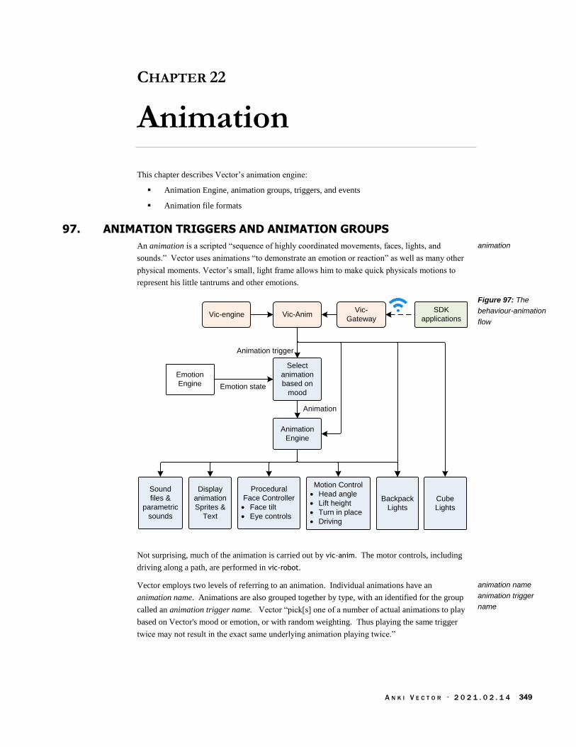
A N K I V E C T O R · 2 0 2 1 . 0 2 . 1 4 349
CHAPTER 22
Animation
This chapter describes Vector’s animation engine:
Animation Engine, animation groups, triggers, and events
Animation file formats
97. ANIMATION TRIGGERS AND ANIMATION GROUPS
An animation is a scripted “sequence of highly coordinated movements, faces, lights, and
sounds.” Vector uses animations “to demonstrate an emotion or reaction” as well as many other
physical moments. Vector’s small, light frame allows him to make quick physicals motions to
represent his little tantrums and other emotions.
Emotion
Engine
Backpack
Lights
Emotion state
Animation trigger
Select
animation
based on
mood
Animation
Animation
Engine
Sound
files &
parametric
sounds
Cube
Lights
Display
animation
Sprites &
Text
Procedural
Face Controller
· Face tilt
· Eye controls
Motion Control
· Head angle
· Lift height
· Turn in place
· Driving
SDK
applications
Vic-
GatewayVic-AnimVic-engine
Not surprising, much of the animation is carried out by vic-anim. The motor controls, including
driving along a path, are performed in vic-robot.
Vector employs two levels of referring to an animation. Individual animations have an
animation name. Animations are also grouped together by type, with an identified for the group
called an animation trigger name. Vector “pick[s] one of a number of actual animations to play
based on Vector's mood or emotion, or with random weighting. Thus playing the same trigger
twice may not result in the exact same underlying animation playing twice.”
animation
Figure 97: The
behaviour-animation
flow
animation name
animation trigger
name

A N K I V E C T O R · 2 0 2 1 . 0 2 . 1 4 350
97.1. FILES
The animation system employs many files, working in concert to effect the animation. The top
level files map trigger names to the next level, which may be groups of animations, display
compositing tables, or (in the case the lights) the patterns to illuminate the lights with. In the case
of animation groups, these further map to sprite sequences to display (which then maps to image
files), and sounds play. The compositing image maps also map to these sprite sequences.
Image MapSprite
Sequence
Animation
JSON & Bin
Backpack
Animation
Trigger Map
Animation
Groups
Image
Layout
Cube Light
Sequence
Cube
Animation
Trigger Map
Backpack
Light
Sequence
Animation
Trigger Map
Composite
Image
Layout Map
Composite
Image Map
Map
WEM
Audio
Files
WEM
Audio
Files
WEM
Audio
Files
Sound
Bank Files
Sound
Bank Files
WEM
Audio
Files
WEM
Audio
Files
PNG
Image
Files
There are seven types of animation files and other animation sources:
JSON files that describe how the backpack lights should behave (see Chapter 23)
JSON files that describe how the cube lights should behave (see Chapter 23)
Binary animation files holding one or more of related animations that coordinate
sophisticated sounds, eye animations, linking together sprite sequences, and coordinate
head & lift movements with driving (see Chapter 27 for details of this file)
JSON animation files are very similar to binary animation files. They hold one or more of
related animations that coordinate sophisticated sounds, eye animations, linking together
sprite sequences, and coordinate head & lift movements with driving (see Chapter TBD for
details of this file)
Sprite sequences (see Chapter 24), which are folders of PNG image files to display in
sequence
Composited screens (see Chapter 24) showing icons and text information driven by the
behaviors and cloud server intents.
Sound files (see Chapter 25) holding pre-recorded sound effects
Procedural animations are generated by vic-anim. These perform text to speech, driving
around obstacles, animating Vector’s eyes, and other tasks that are not practical to script in
a file.
And there are four kinds of files gluing these together:
JSON files that map the trigger names to the animation groups, and to the backpack and
cube light animations. (These will be described below.)
Figure 98: The
behaviour-animation
flow

A N K I V E C T O R · 2 0 2 1 . 0 2 . 1 4 351
The animation group files with rules on how to select one or more individual animations,
including with the weighted randomization and emotion filters. (These will be described
below.)
The animation binary file may direct a sprite sequence and/or audio file to play. These will
be described in Chapter 27
JSON files to layout the display; these may call out animation sequences and places to
composite icons and text. These will be described in Chapter 24
97.2. NAMING CONVENTIONS
Helpfully, many of the animation files in the resource folders follow a naming convention. The
prefix in the name indicates its intended use:
Prefix Used by
ag_ Animation groups
anim_ Animation files (both binary and JSON)
face_ A sprite sequence
The files mapping a name to other files, or other information, end with “Map”.
The names of the animation clips start with the base name of the animation file that contains them.
(It may even be the same name). This makes it easier to find the animation file given the clip
name.
97.3. TRIGGER MAP CONFIGURATION FILES
The list of animation triggers provided to the SDK is built into libcozmo_engine.so. The internal
configuration files support a much wider range of animation triggers; it is not known if passing
one these will work, or will be filtered out.
The animation trigger name is mapped to an animation file (and group of animations). The table
that defines this mapping is found in the following file:
/anki/data/assets/cozmo_resources/ assets/cladToFileMaps/AnimationTriggerMap.json
(This path is hardcoded into libcozmo_engine.so.)
The format of the files is the same. The file is an array of structures. Each structure has the
following fields:
Field Type Description
AnimName string The name of the animation group. This is the name of a
JSON file, without the “.json” suffix.
CladEvent string This is the animation trigger name to match when looking
up the animation.
The cube’s and backpack light animation file name is usually the same as the trigger, except that
the first letter is lower case.
Table 491: Animation
file prefixes
mapping trigger
names to animation
groups
Table 492: JSON
structure mapping
trigger name to
animation group

A N K I V E C T O R · 2 0 2 1 . 0 2 . 1 4 352
97.4. ANIMATION GROUP FILES
In the “AnimationTriggerMap.json” file (describe above), the “AnimName” field value maps (when
the suffix “,json” is appended) to animation groups are located in the following folder tree:
/anki/data/assets/cozmo_resources/ assets/animationGroups
This path is hardcoded into libcozmo_engine. Inside are folders (grouping the animation groups),
each of which holds the JSON files. By convention, the animation group file names are all lower
case. Some names may look similar to the trigger name (but not always).
Each animation group JSON file is a structure with the following fields:
Field Type Description
animations AnimationGroupItem[] An array of animations to select from to play.
The AnimationGroupItem structure describes the specific animation clip to use. It may also
specify some head movement, with some variability; this is optional. The structure has the
following fields:
Field Type Units Description
CooldownTime_Sec float seconds The minimum duration, after this animation has completed,
before it can be used again. Typically 0.0
HeadAngleMin_Deg float degree The head is to move to random angle greater (or equal) to
this. This should be in the range -22.0° to 45.0°. Only
used if UseHeadAngle is true.
HeadAngleMax_Deg float degree The head is to move to random angle les than (or equal) to
this. This should be in the range -22.0° to 45.0°. Only used
if UseHeadAngle is true.
Mood string emotion name
The name of a “simple mood” that should be applied or
“Default”. See Chapter 29 for more information on simple
moods.
Name string The name of the animation clip to play. This clip is defined
within one of the animation binary files. The binary file
(without the “.bin” suffix) or the JSON file (without the
“.json” suffix) for the animation.
UseHeadAngle bool If true, this enables the head to be moved to some random
within the specified range. Optional, default is false
Weight float How much “weight’ to give to this entry. Typically 1.0
The possible animations are screened for being applicable to the current emotional state (with
Mood). The result set is randomly selected from: The weights (of the select items) are summed up
and normalized, giving the probability that that entry would be selected.
98. ANIMATIONS
98.1. ANIMATION TRACKS
Each animation may use one more tracks. The tracks can control:
The display graphics – compositing a movie , text, and eyes layers
animation groups
Table 493: Animation
group file JSON
structure
Table 494:
AnimationGroupItem
structure
animation tracks

A N K I V E C T O R · 2 0 2 1 . 0 2 . 1 4 353
Animating the backpack and cube lights
Audio effects
Moving the head
Moving the lift
Moving the treads, or navigating
When an animation is played, it locks the tracks that it is using, for the duration of the animation.
If one of the tracks that it needs to use is already locked, the animation can’t be played (and
generates an internal error).
When an animation is submitted to be played, a several of tracks (the lift, head and body) can be
flagged to be ignored if they already used elsewhere by animation system.
98.2. ANIMATION FILES
There are two kinds of files: binary and JSON files. The animation binary files are held in the
following folder:
/anki/data/assets/cozmo_resources/ assets/animations
This path is hardcoded into vic-anim. Each of these files may contain several animations (called
clips). By convention, the name of the animation starts with the name of the file. See Chapter 27
for a detailed description of these files.
98.3. ANIMATION NAMES MANIFEST
A list of animation names and their duration is located in manifest file at:
/anki/data/assets/cozmo_resources/ assets/sprites/anim_manifest.json
This path is hardcoded into libcozmo_engine. The file is an array of structures. Each structure
has the following fields:
Field Type Units Description
length_ms int ms The duration of the animation (when played)
name string The name of the animation clip within one of the animation
binary or JSON files.
99. SDK COMMANDS TO PLAY ANIMATIONS
The HTTPS SDK includes commands to list and play animations.
A list of animations triggers can be retrieved with the List Animation Triggers command
(see Chapter 15 section 48.3 List Animation Triggers).
A list of animations can be retrieved with the List Animation command (see Chapter 15
section 48.2 List Animations).
An animation can be play by selecting the animation trigger (see Chapter 15 section 48.5
Play Animation Trigger command). Vector will select the specific animation from the
group. Or,
animation duration
manifest
Table 495: JSON
structure mapping
animation name to
duration

A N K I V E C T O R · 2 0 2 1 . 0 2 . 1 4 354
An animation can be play by the giving the specific animation name (see Chapter 15
section48.4 Play Animation).
As the individual animations are low-level they are the most likely to change, be renamed or
removed altogether in software updates. Anki strongly recommends using the trigger names
instead. “Specific animations may be renamed or removed in future updates of the app.”

A N K I V E C T O R · 2 0 2 1 . 0 2 . 1 4 355
CHAPTER 23
Lights Animation
This chapter describes the light animations:
The Cube Spinner game, which is one user of this type of lights animation
Backpack Lights animation
Cube Lights Animation
100. LIGHTS ANIMATION OVERVIEW
The backpack lights are used to show the state of the microphone, charging, WiFi and some other
behaviours. The companion cube lights are show setting up the cube, entertainment while Vector
is interacting with it, and for games. There are three interrelated sources of light animation.
Animation binary file to animate the backpack lights. This drives most of the light
animation.
JSON files for the Cube and backpack light animation. There are four kinds of JSON files:
files for the Cube’s light sequence, files for the backpack light sequence, two files to map
animation trigger names to each of those light sequences.
The Cube Spinner game, which is a notable client of the JSON-driven light animations..
The light animations may be triggered by the cube spinner game configuration, or by behaviors
(within libcozmo_engine), such as those related to exploring, interaction, pouncing etc.
The companion cube and backpack light animations are very similar, so they have been grouped
here for discussion.
101. CUBE SPINNER GAME
The cube spinner game was “like a little roulette wheel on the cube. The lights would spin
around and you and Vector competed to make them stop at the right combination.” Although
developed early, it was not enabled in any of the Anki software releases. It is thought that
version 1.7 would have enabled it.
The Cube Spinner game’s configuration file is located with the behavior folders:
/anki/data/assets/cozmo_resources/ config/engine/behaviorComponent/cubeSpinnerLight
Maps.json
This is path hardcoded into libcozmo_engine.
cube spinner game

A N K I V E C T O R · 2 0 2 1 . 0 2 . 1 4 356
This configuration file is unlike the behavior files in that it doesn’t have a behavior class or ID. It
is used to map game events to animation triggers for backpack and cube lights. The events names
are defined in libcozmo_engine.so. The configuration file structure has the following fields:
Field Type Description
lightMap LightMap[] This is an array of alternatives mappings from
events to the animation triggers.
playerErrorCubeLights string The animation trigger name for the
playerErrorCubeLights event.
startGameCubeLights string The animation trigger name for the
startGameCubeLights event.
Each of the LightMap structures has the following fields:
Field Type Description
backpackLights BackpackLightMap This structure maps event to animation trigger
names appropriate for the backpack light
animation.
cubeLights CubeLightMap This structure maps event to animation trigger
names appropriate for the cube light animation.
debugColorName string A name like “blue”. This likely is used to provide
the active mapping to a tool during development.
BackpackLightMap is a structures used to map an event to an animation trigger name. The
animation trigger name is mapped to backpack light animation, see chapter 22. This structure has
the following fields:
Field Type Description
celebration string The animation trigger name for the celebration
event.
holdTarget string The animation trigger name for the holdTarget
event.
selectTarget string The animation trigger name for the selectTarget
event.
CubeLightMap is a structures used to map an event to an animation trigger name. The animation
trigger name is mapped to cube light animation, see chapter 22. This structure has the following
fields:
Field Type Description
celebration string The animation trigger name for the celebration
event.
cycle string The animation trigger name for the cycle event.
locked string The animation trigger name for the locked event.
lockedPulse string The animation trigger name for the lockedPulse
event.
lockIn string The animation trigger name for the lockIn event.
Table 496: Cube
spinner light map JSON
structure
Table 497: LlightMap
JSON structure
Table 498:
BackpackLightMap
JSON structure
Table 499:
CubeLightMap JSON
structure

A N K I V E C T O R · 2 0 2 1 . 0 2 . 1 4 357
102. BACKPACK LIGHTS ANIMATION
The sequence to illuminate the backpack lights is found by
1. The Cube Spinner name produces an animation trigger name
2. The animation trigger name is mapped to an animation file
3. The animation file provides the sequence to illuminate the backpack lights.
102.1. TRIGGER MAP CONFIGURATION FILES
The table mapping the animation trigger name to the backpack lights animation file is found in
the following file:
/anki/data/assets/cozmo_resources/ assets/cladToFileMaps/BackpackAnimationTriggerM
ap.json
This path is hard coded into vic-anim. This file maps the trigger name to the name of the animation
file. The file’s schema is the same as in Chapter 22, section 97.3 Trigger Map Configuration files
102.2. THE BACKPACK LIGHTS PATTERN
Vic-anim controls the backpack lights based on specifications in JSON files in
/anki/data/assets/cozmo_resources/ config/engine/lights/backpackLights/
The path is hard coded into vic-anim. All of the JSON files have the same structure with the
following fields:
Field Type Units Description
offColors array of 3 colors
RGBA Each color corresponds to each of the 3 lower back pack
lights. Each color is represented as an array of 4 floats (red,
green, blue, and alpha), in the range 0..1. Alpha is always 1.
offPeriod_ms int[3] ms The “off” duration for each of the 3 back pack lights. This is
the duration to show each light in its corresponding “off” color
(in offColors).
offset int [3] ms This holds how many milliseconds each light’s clock is
advanced from the clock driving the animation. This is used to
stagger each lights progression through the animation
sequence.
onColors array of 3 colors
RGBA Each color corresponds to each of the 3 lower back pack
lights. Each color is represented as an array of 4 floats (red,
green, blue, and alpha), in the range 0..1. Alpha is always 1
(the value is ignored).
onPeriod_ms int[3] ms The “on” duration for each of the 3 lights. This is the duration
to show each light in its corresponding “on” color (in
onColors).
transitionOffPeriod_ms int [3] ms The time to transition from the on color to the off color.
transitionOnPeriod_ms int [3] ms The time to transition from the off color to the on color.
mapping trigger
names to light
sequences
Table 500: The
Backpack LEDs JSON
structure

A N K I V E C T O R · 2 0 2 1 . 0 2 . 1 4 358
Note: These sequences do not have the parametric variation based on emotion or random
weighting.
103. CUBE LIGHTS ANIMATION
The sequence to illuminate the backpack lights is found by
1. The Cube Spinner name produces an animation trigger name
2. The animation trigger name is mapped to an animation file
3. The animation file provides the sequence to illuminate the cube lights.
103.1. TRIGGER MAP CONFIGURATION FILES
The table mapping the animation trigger name to the cube lights animation file is found in the
following file:
/anki/data/assets/cozmo_resources/ assets/cladToFileMaps/CubeAnimationTriggerMap.jso
n
This path is hardcoded into libcozmo_engine.so. This file maps the trigger name to the name of
the animation file.
The file’s schema is the same as in Chapter 22, section 97.3 Trigger Map Configuration files,
103.2. CUBE ANIMATIONS
The cube light animation files are located in:
/anki/data/assets/cozmo_resources/ config/engine/lights/cubeLights
and within folders (and sub-folders) therein. This path is hard-coded into libcozmo-engine.
All of the cube light animation JSON files have the same structure. They are an array of structures.
(There is usually one item, but there may be more.) Each structure may contain the following
fields:
Field Type Units Description
canBeOverridden Default is true. Optional.
duration_ms float ms If zero, do this until told to stop, otherwise perform the animation
for this period and proceed to next structure or stop.
pattern see below A structure describing the light patterns. Described below.
patternDebugName string A text name that is associated with this structure. Optional.
Table 501: The Cube
LEDs JSON structure

A N K I V E C T O R · 2 0 2 1 . 0 2 . 1 4 359
The pattern structure contains the following fields:
Field Type Units Description
offColors array of 4 colors
RGBA Each color corresponds to each of the 4 cube lights. Each
color is represented as an array of 4 integers (red, green, blue,
and alpha), in the range 0..255. Alpha is always 255.
offPeriod_ms int[4] ms The “off” duration for each of the 4 cube lights. This is the
duration to show each cube light in its corresponding “off”
color (in offColors).
offset int[4] This holds how many milliseconds each light’s clock is
advanced from the clock driving the animation. This is used to
stagger each lights progression through the animation
sequence.
onColors array of 4 colors
RGBA Each color corresponds to each of the 4 cube lights. Each
color is represented as an array of 4 integers (red, green, blue,
and alpha), in the range 0..255. Alpha is always 255.
onPeriod_ms int[4] ms The “on” duration for each of the 4 cube lights. This is the
duration to show each cube light in its corresponding “on”
color (in onColors).
rotate boolean ? Possibly to have the colors be assigned to the next clockwise
(or counterclockwise) light periodically?
transitionOffPeriod_ms int[4] ms The time to transition from the on color to the off color.
transitionOnPeriod_ms int[4] ms The time to transition from the off color to the on color.
This structure is very similar to that used by the backpack lights. The obvious differences are:
There are 4 lights (instead) of three,
The RGBA value range is 0..255; and
There is a boolean “rotate” field.
Table 502: The Cube
LEDs pattern structure

A N K I V E C T O R · 2 0 2 1 . 0 2 . 1 4 360
CHAPTER 24
Video Display & Face
Vector’s LCD is used to display his face, which conveys his mood and forms an emotional
connection with his human, and to display the results of behaviour interactions:
The image compositor
The sprite manager
Animated compositions
Procedural face
104. OVERVIEW OF THE DISPLAY
Vector displays imagery – often moving imagery – on his display. The items drawn on the screen
include:
Full screen sprites — each frame is a PNG image that covers the whole display. A
sequence of frames (PNGs) is drawn regularly to create the animated effect.
Composited images and text
Procedural face to draw the face in a complex way (more on this later)
The first two are used as part of behaviors and intents. A visual “movie” is shown when the
behavior starts and another is to provide the response. The compositor map allows mixing in
iconography, digits and text to show information in the response.
Vector’s eyes are drawn in one of two ways:
Using the full-screen sprites above, with the eyes pre-drawn in the PNG’s
Using procedural face which synthesizes the eyes
Note: the sprite and procedural face can be drawn at the same time, with sprites drawn over the
eyes. This is done to create weather effects over Vector’s face.
104.1. ORIGIN
The display system – especially the procedural face module – was pioneered in Cozmo. To
prevent burn in and discoloration of the OLED display, Cozmo was given two features. First,
Cozmo was given regular eye motion, looking around and blinking. Second, the illuminated rows
were regularly alternated to give a retro-technology interlaced row effect, like old CRTs.
Vector’s eyes are more refined, but kept the regular eye motion. The interlacing was made
optional, and disabled by default.
US Patent 20372659

A N K I V E C T O R · 2 0 2 1 . 0 2 . 1 4 361
104.2. RENDERING SYSTEM
The display is layered, placing sprites on top, followed by the compositional layout and, finally,
the procedural face.
PNGPNGSprite (PNG)
LayerComposition
layer
Procedural face
The rending and compositing these different layers look like:
Sprite
Animation
Color
Preferences
Procedural
Face
Composition
Image buffer
Image
Python SDK
applicationsVic-Gateway
Vision
processingCamera
MIPI
As a functional flow, the top level is:
Load PNGComposite
onto buffer
Render
Procedural
Face
LCD displaySend
changes SPI
104.2.1 Frame buffer
Prior to version 1.0, Vector used the kernel-based frame buffer (/dev/fb0). The frame buffer
driver was responsible for buffering the screen image, then transferring it via SPI to the LCD. The
frame buffer device driver also tracks the width and height of the screen, and the pixel format, and
making the pixel memory available as buffer that processes could memory-map to composite to.
Vector switched to using TBD in the application software to composite the frame, and to transfer
the changes to the LCD. It skipped the kernel drivers, except the SPI driver. The effective frame
rate was sped up by sending only the changes.
The applications vic-anim, vic-boot-anim, and vic-rescue still reference the frame-buffer /dev/fb0.
This is most likely compatibility or fall-back support, and would have been removed in a future
release.
Figure 99: The
display layers
Figure 100: The
display animations
composition
Figure 101: The
display animations
functional flow

A N K I V E C T O R · 2 0 2 1 . 0 2 . 1 4 362
105. IMAGE LAYOUT, COMPOSITION, AND SPRITE SEQUENCES
The animation system maps some trigger names to:
A screen layout defining rectangular areas on the display (called sprite boxes) where
images and sprite sequences will be drawn.
Sprite sequence to display in the layout areas. Not all screen layouts have an associated
sprite sequence.
These forms are only used by a couple of behaviors, to support the weather, timers, and the
blackjack game. Version 1.7 began the process of migrating to a slightly different structure that
used the binary animation file.
105.1. BOOT ANIMATION
Vector, while his system starts up, plays an animation on the screen. The boot animation file is a
series of uncompressed frames that are played in a loop. Each frame is 184x96 pixels; each pixel
is in the RGB565 format. This boot animation is held in the following file:
/anki/data/assets/cozmo_resources/config/engine/animations/boot_anim.raw
The full path is hardcoded into vic-bootAnim.
105.2. MAPPING ANIMATION TRIGGER NAMES TO LAYOUTS
There are two related files used to map animation trigger names to the layout and possible sprite
sequence to display.
105.2.1 Maps to layout
The table mapping the layout trigger name to the layout file is found in the following file:
/anki/data/assets/cozmo_resources/ assets/cladToFileMaps/CompositeImageLayoutMap.js
on
This path is hardcoded into libcozmo_engine.so. The format of the file is an array of structures.
Each structure has the following fields:
Field Type Description
CladEvent string This is the layout trigger name to match when looking up
the animation. (This name is also defined in
libcozmo_engine)
LayoutName string The name of the JSON file (without the “.json” suffix) for
the animation.
105.2.2 Maps to Image maps
The following table is used to translate an map trigger name to an image map. This translation
table is:
/anki/data/assets/cozmo_resources/ assets/cladToFileMaps/CompositeImageMapMap.json
Table 503: JSON
structure mapping
trigger name to
composite image layout
map

A N K I V E C T O R · 2 0 2 1 . 0 2 . 1 4 363
This path is hardcoded into libcozmo_engine.so. The format of the file is an array of structures.
Each structure has the following fields:
Field Type Description
CladEvent string This is the map trigger name to match when looking up the
animation. (This name is also defined in libcozmo_engine)
MapName string The name of the JSON file (without the “.json” suffix) for
the animation.
105.3. LAYOUT FILE
A screen layout defines rectangular areas on the display where images and sprite sequences will be
drawn. The layouts are held in folders within:
/anki/data/assets/cozmo_resources/ assets/compositeImageResources/imageLayouts
This path is hardcoded into libcozmo_engine.
Each layout is formatted as the array of zero or more structures, although most have a single
structure. Each structure has the following fields:
Field Type Description
images SpriteBox[] An array of sprite boxes for showing icons and other
images.
layerName string The name of the layer. (This name is also defined in vic-
anim and libcozmo_engine) The animation engine may use
this to select the procedure(s) in charge managing the layer
and sprite boxes.
A sprite box defines a rectangular region on the display to draw an imagefrom a file. Each
SpriteBox structure has the following fields:
Field Type Units Description
height int pixels The height of the sprite box. This should be less than or
equal to 96.
spriteBoxName string The name of the sprite box. (This name is also defined in
vic-anim and libcozmo_engine.) The animation engine may
use this to select the procedure(s) in charge managing the
layer and sprite boxes. If an image map is available for this
animation, the sprite sequence it describes will be displayed
in this rectangle.
spriteRenderMethod string “CustomHue” if the PNG images should be converted from
gray scale to the colour using the current eye colour setting.
“RGBA” if the image should be drawn as is.
width int pixels The width of the sprite box. This should be less than or
equal to 184.
x int pixel The x coordinate of the upper left hand corner of the sprite
box. The x coordinate can be outside of the display area;
only the portion of the image within the display area
(0..183) will be shown. This allows an image to slide in.
Table 504: JSON
structure mapping an
animation trigger name
to an image map
Table 505: Display
layout JSON structure
Table 506: Sprite box
JSON structure placing
an image on the display

A N K I V E C T O R · 2 0 2 1 . 0 2 . 1 4 364
y int pixel The y coordinate of the upper left hand corner of the sprite
box. The y coordinate can be outside of the display area;
only the portion of the image within the display area (0..95)
will be shown. This allows an image to slide in.
See also Chapter 27 section 117.16 RobotAudio for an alternate method to define a sprite box.
105.4. IMAGE MAP FILE
An image map describes which sprite sequence to display (it just has a lot of extra steps). The
image map files are held in folders within:
/anki/data/assets/cozmo_resources/ assets/compositeImageResources/imageMaps
This path is hardcoded into libcozmo_engine.
Each image map file is formatted as the array of zero or more structures, although most have a
single structure. Each structure has the following fields:
Field Type Description
images SpriteMapBox[] An array of sprite boxes for showing sprite sequences.
layerName string The name of the layer. This name is also defined in vic-
anim and libcozmo_engine. The animation engine may use
this to select the procedure(s) in charge managing the layer
and sprite boxes.
Each SpriteMapBox structure has the following fields:
Field Type Units Description
spriteBoxName string The name of the sprite box. (This name is also defined in
vic-anim and libcozmo_engine.)
spriteName string The name of a sprite sequence. Note: the case of this string
may differ from the case used in the sprite sequence folder
name.
105.5. INDEPENDENT SPRITES
Independent sprites are PNG files. These image files are held in the following folders:
/anki/data/assets/cozmo_resources/ assets/sprites/independentSprites
/anki/data/assets/cozmo_resources/ config/sprites/independentSprites
/anki/data/assets/cozmo_resources/ config/facePNGs
/anki/data/assets/cozmo_resources/ config/devOnlySprites/independentSprites
These paths are hardcoded into libcozmo_engine, vic-anim. and vic-faultCodeDisplay. Not all of the
images in those paths are used.
The independent sprite PNG files can be any size so long as it fits within the width and height of
the display (184x96). The images may be colored, or in gray scale with an alpha channel. If the
sprite is grey-scale, it will be colourized with the current eye colour setting, using the gray scale for
the pixel brightness level.
Table 507: Image map
JSON structure
Table 508: Sprite map
box JSON structure
independent sprites
A N K I V E C T O R · 2 0 2 1 . 0 2 . 1 4 365
105.6. SPRITE SEQUENCES
Sprite sequences are PNG files that are displayed sequentially– each PNG makes up each frame
of the animation. These image files are held in folder with the same name as the sprite sequence
name. The sprite sequence folders are held in:
/anki/data/assets/cozmo_resources/ assets/sprites/spriteSequences
/anki/data/assets/cozmo_resources/ config/sprites/spriteSequences
and
/anki/data/assets/cozmo_resources/ config/devOnlySprites/spriteSequences
These paths are hardcoded into libcozmo_engine. Note: the folder name may have a different case
than the sprite sequence name used by the SpriteMapBox or the animation; the name should be
matched in a case insensitive manner.
The sprite sequence PNG files are sized to fill the display. The images must match the width and
height of the sprite box they are displayed in, or the display (184x96) if they are employed by a
binary animation file. The images may be colored, or in gray scale with an alpha channel. If the
sprite is grey-scale, it will be colourized with the current eye colour setting, using the gray scale for
the pixel brightness level.
These sprites are displayed as a sequence. The frame number is appended to the file name – range
from 2 to 5 digits – starting with 0. The frame rate is computed from the number of images in the
sequence (the number of frames) divided by the duration of the animation (given in the animation
manifest) that it is associated with.
The images are composited on top of the eye layer. The eyes may haven be turned off, or they may
be present.
105.7. DISPLAYING TEXT ON THE SCREEN
When Vector is operating, almost all of the text displayed is composited from image files (sprites).
There are two additional procedures that Vector can use to put text on the display:
drawTextOnScreen() (part of libcozmo_engine)
OpenCV’s putText() (part of OpenCV)
These are procedures are only used in exceptional circumstances. (The typeface is inelegant, if
they were something Vector used more frequently; undoubtedly they’d have improved typeface
designs.) They are used to display the fault codes (via Vic-faultCodeDisplay), when the system is
unable to operate the software; and to display information on the customer care information screen
(CCIS) in vic-anim.
sprite sequences

A N K I V E C T O R · 2 0 2 1 . 0 2 . 1 4 366
106. PROCEDURAL FACE
Vector’s dynamic, moving eyes are brilliant, forming the gateway for an emotion connection.
They allow Vector to give eye contact, facial expressions, and his current sentiment. These eyes
are drawn by the procedural face manager.
The parameters of the face controls are divided into the overall view of the face and the individual
characteristics of each eye:
Face center
scale
Y
angle
scale X
Hotspot
Center
The high level face animation parameters include:
The color to draw the eyes in. Vector’s eye color is a preference setting, but can be
temporarily overridden by the SDK.
The position of the center of the face
The angle of the face; tilt (or rotation) of the face gives the impression of tilting the head
The scaling of the height and width of the face
The illusion of gaze – the intuition that Vector is looking at something – is achieved by
giving each eye a soft spherical rounding effect. The center of the shading, the equivalent
of a pupil, may be moved around the eye area. This gives a sense of where Vector is
looking – and by moving the center, Vector can appear to be looking around. Coordinated
with the face detector, Vector can make (and maintain) direct eye contact.
The outer shape of the eyes, which gives a sense of the emotions – smiling, frustration,
sleep etc.
There is a scan line opacity factor. This controls how much alternating lines are
illuminated and darkened. A value of 1.0 has odd and even lines with the same coloring.
Where the eyes are looking is controlled within the procedural face manager, rather than in the
animation files. It controls the blink rate, the focus of the eyes and how much the eyes dart around.
The manager contributes looking at a face and making eye contact.
procedural face
Figure 102: Face
control points
face parameters
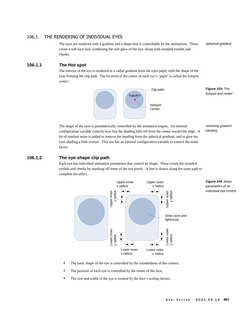
A N K I V E C T O R · 2 0 2 1 . 0 2 . 1 4 367
106.1. THE RENDERING OF INDIVIDUAL EYES
The eyes are rendered with a gradient and a shape that is controllable by the animations. These
create a soft-face feel, combining the soft glow of the eye, along with rounded eyelids and
cheeks.
106.1.1 The Hot spot
The interior of the eye is rendered as a radial gradient from the eyes pupil, with the shape of the
eyes forming the clip path. The location of the center of each eye’s ‘pupil’ is called the hotspot
center:
Clip path
Hotspot
Center
Falloff
The shape of the eyes is parametrically controlled by the animation engine. An internal
configuration variable controls how fast the shading falls off from the center toward the edge. A
bit of random noise is added to remove the banding from the spherical gradient, and to give the
eyes shading a little texture. This too has an internal configuration variable to control the noise
factor.
106.1.2 The eye-shape clip path
Each eye has individual animation parameters that control its shape. These create the rounded
eyelids and cheeks by masking off some of the eye pixels. A line is drawn along the outer path to
complete the effect.
Upper inner
x radius
Upper outer
x radius
Lower inner
x radiusLower outer
x radius
Up
pe
r o
ute
r
y r
ad
ius
Lo
we
r o
ute
r
y r
ad
ius
Up
pe
r in
ne
r
y r
ad
ius
Lo
we
r in
ne
r
y r
ad
ius
Glow (size and
lightness)
The basic shape of the eye is controlled by the roundedness of the corners.
The position of each eye is controlled by the center of the face;
The size and width of the eye is created by the face’s scaling factors
spherical gradient
Figure 103: The
hotspot and center
removing gradient
banding
Figure 104: Basic
parameters of an
individual eye control
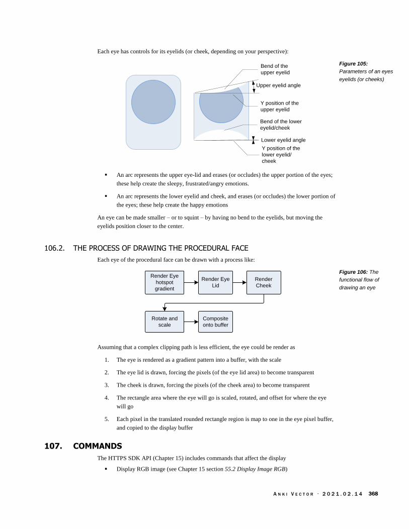
A N K I V E C T O R · 2 0 2 1 . 0 2 . 1 4 368
Each eye has controls for its eyelids (or cheek, depending on your perspective):
Bend of the
upper eyelid
Y position of the
upper eyelid
Upper eyelid angle
Bend of the lower
eyelid/cheek
Lower eyelid angle
Y position of the
lower eyelid/
cheek
An arc represents the upper eye-lid and erases (or occludes) the upper portion of the eyes;
these help create the sleepy, frustrated/angry emotions.
An arc represents the lower eyelid and cheek, and erases (or occludes) the lower portion of
the eyes; these help create the happy emotions
An eye can be made smaller – or to squint – by having no bend to the eyelids, but moving the
eyelids position closer to the center.
106.2. THE PROCESS OF DRAWING THE PROCEDURAL FACE
Each eye of the procedural face can be drawn with a process like:
Rotate and
scale
Composite
onto buffer
Render Eye
Lid
Render
Cheek
Render Eye
hotspot
gradient
Assuming that a complex clipping path is less efficient, the eye could be render as
1. The eye is rendered as a gradient pattern into a buffer, with the scale
2. The eye lid is drawn, forcing the pixels (of the eye lid area) to become transparent
3. The cheek is drawn, forcing the pixels (of the cheek area) to become transparent
4. The rectangle area where the eye will go is scaled, rotated, and offset for where the eye
will go
5. Each pixel in the translated rounded rectangle region is map to one in the eye pixel buffer,
and copied to the display buffer
107. COMMANDS
The HTTPS SDK API (Chapter 15) includes commands that affect the display
Display RGB image (see Chapter 15 section 55.2 Display Image RGB)
Figure 105:
Parameters of an eyes
eyelids (or cheeks)
Figure 106: The
functional flow of
drawing an eye

A N K I V E C T O R · 2 0 2 1 . 0 2 . 1 4 369
Mirror display (see Chapter 15 section 55.3 Enable Mirror Mode)
108. REFERENCES AND RESOURCES
Monson, Nathaniel;Andrew Stein, Daniel Casner, Reducing Burn-in of Displayed Images, Anki,
US Patent 20372659 A1; 2017 Dec 28
Osipa, Jason, Stop Staring: Facial Modeling and Animation Done Right, 3rd Edition, 2010.
This “is a wonderful book on rigging eyes for 3D animation... that focuses on setting up eye
and face controllers.” (Mooly Segal)
https://github.com/juj/fbcp-ili9341
This is an interesting project to study for those who wish to look more into how differential
updates can be implemented.

A N K I V E C T O R · 2 0 2 1 . 0 2 . 1 4 370
CHAPTER 25
Audio Production
This chapter describes how Vector produces sounds and the audio output system:
An overview of the audio output
Text to speech
Audio Effects
109. SPEAKER
Vector uses sound to convey emotion and activities, to speak, and to play sounds streamed from
SDK applications and Alexa’s remote servers. There are five sources of sound:
Sound effects from playing pre-recorded audio files
Sound effects from parametrically generating audio
Sound from an audio stream sent by the SDK application to Vector
Text to speech
A sound stream from Alexa Voice Services
To support this, Vector includes a sophisticated audio architecture:
Alexa
SpeakerALSA
Text To Speech
Acapela Engine
MPG123
SDK
applications
Vic-
GatewayVic-Anim
libaudio_engine
AudioKinetic Wwise
Vic-Engine
Compression is not used to send audio from SDK applications to Vector. The vic-engine passes
the received samples to audio engine to mix in its playback.
Figure 107: The audio
output architecture

A N K I V E C T O R · 2 0 2 1 . 0 2 . 1 4 371
Some key elements of the audio production are:
Element Description
ALSA This is Linux’s sound player, which provides the device drivers to allow software access to the
speaker.
Alexa Voice Services These are a set of remote servers that provide an audio stream of Alexa’s voice responses,
music, and other sounds.
libaudio_engine This is Vector’s sound framework. It is built on AudioKinetic’s Wwise framework. It handles
audio file loading and playback, sound effects, and others.
MPG123 The MPG123 is used to decode the sound stream sent from Alexa Voice Services servers.
Text to Speech The text to speech facility is used to convert text (written sentences) to spoken words. This is
built on Acapela’s speech engine.
110. SOUND EFFECTS FROM AUDIO FILES AND PROCEDURES
Vector uses AudioKinetic’s Wwise (WaveWorks Interactive Sound Engine) toolkit for sound
playback. Wwise is one of the most popular high-end game sound frameworks. It has
sophisticated composition tools, extensive documentation, and a redistributable player for many
platforms. Such a powerful tool seems overkill on device with only one output channel and a
tiny speaker. In context, it makes sense.
Wwise was used in Cozmo’s mobile application. The application which was designed as a kind of
video game, and employs a lot video game design approaches. So it makes senses that an audio
tool targeting video games would be used there. In turn, Vector is draws on Cozmo’s frameworks–
both the mobile application and what ran on the hardware – and creation tools it isn’t surprising
that the same framework would be employed by Vector.
The key features of Wwise (at least for Vector) are:
Triggering sound effects, muting sounds, and changing parameters of sound playback (by
sending the framework audio events)
Playing pre-recorded sounds, including looping
Playing procedural sounds
Playing music (in the case of Cozmo)
Sound effects, including fading
Change the sample rates from different sources to the one played
Mixing different sound sources together
Managing a library of files that specify how to respond to audio events, how to create
music and sound effects, and can hold pre-recorded sounds.
Table 509: The audio
systems functional
elements
AudioKinetic Wwise

A N K I V E C T O R · 2 0 2 1 . 0 2 . 1 4 372
110.1. SOUND PLUGINS
The Wwise framework provides hooks that allow it to be integrated into the rest of the software
system, and given extra functionality. This is accomplished by plug-in modules:
Audio
Engine
ALSA
Krotos
Vocoder
HijackStreaming
Wave
Portal
Wave
Portal
The most import plug-ins are the ones receiving the audio output (aka “sink” plug-ins). This is
how the audio sounds are taken from the audio engine and sent to Vectors speaker.
The ALSA plug-in gathers the audio output and passes it to the “Advanced Linux Sound
System” (ALSA) sound handler, which in turn passes it thru to Qualcomm’s audio driver.
The Hijack plug-in is probably unused on Vector, but is used on desktop computers to
allow recording of Vector’s sounds…? (It may also have been intended to be used as part
of the message-recording, with the microphone audio piped thru the audio engine to be
filtered/cleaned, and then saved.)
There are two plug-ins allowing audio from external sources to be processed by the audio engine
and delivered to Vector’s speaker:
Wave Portal
Streaming Wave portal. This receives the audio sounds from vic-engine for playback
Finally, there are the sound effects plug-ins:
The Krotos “Dehumaniser” vocoder is used to give Vector his unique vocal qualities.
plug-ins
Figure 108: Plug-ins
in the Wwise audio
pipeline

A N K I V E C T O R · 2 0 2 1 . 0 2 . 1 4 373
110.2. AUDIO PIPELINE
In a sense, Wwise can be thought of having multiple, configurable pipelines to produce sound.
Each “game object” –perhaps a character, tool or machine, etc. – have its own pipelines for each
kind of sound/sound-effect it would make:
Audio Switch
Audio State
Sound files,
effects
Sound files,
effects
Sounds,
effects
Select
Audio Event
Parameter SettingKey Value
Parameters
Key Value
States
Action(s)
Audio Switch
Categorization
The audio pipeline is driven by audio events it receives from the main application. These events
are like the animation triggers. The metaphor is that when something occurs in the application
(usually a video game), it represents this as an event distributed to a variety of subsystems to
respond to, including the audio engine. Typically an event will cause the audio engine to play a
sound, but the event system is much more powerful than that. Events trigger an action, which is
the heart of the pipeline, and it is the action that plays the sound. The actions, in turn, can be
configured to change sound parameters, stop playback, and so on:
“[Audio] events apply actions to the different sound objects or object groups in your
project hierarchy. The actions you select specify whether the Wwise objects will play,
stop, pause, .. mute, set volume, enable effect bypass, and so on.”
The Wwise framework employs event ID numbers to refer to events. Events can also be referred
to using lexical names – as strings. A later section will describe how to translate a string to an
event ID.
Audio parameters are settable values used by the actions that control how they sound. Vector
mainly uses these to adjust the sounds based on his current mood and activity. Like the action,
these parameters are on a per object (within the audio engine) basis.
An audio state is used to set the context for sound system overall, so that the right sounds and
effects are used in responding to events, and actions general across all of the game objects.
An audio switch is similar, but it sets up the context so that the right sound (or sound effect, etc)
is used for a particular object or event. AudioKinetic gives an example of foot-step events
triggering a footstep sound but the audio switch is set to the kind of surface that is being walked
on – selecting walking on grass, gravel, pavement, etc. . A switch can be automatically set by a
parameter, if it is set up to use different value thresholds to categorize it into one of the switch
states.
Figure 109: Overview
of the Wwise audio
pipline
audio event
audio action
WWise documentation
audio parameter
audio state
audio switch

A N K I V E C T O R · 2 0 2 1 . 0 2 . 1 4 374
110.3. HOW VECTOR USES WWISE
Vector’s design uses Wwise features to give a more life-like quality to his sounds. The sounds are
triggered in two different ways:
The binary animation file can trigger sending audio events (by ID), setting parameters,
states and switches. See Chapter 27, section 117 for more information.
The behaviors may emit audio events to convey Vector’s emotional state – sadness,
approval, etc. See Chapter 28, section 119.8 Audio events for more information.
To provide variation, when an audio event is received by the audio engine, it does not play just a
single, fixed sound file. Instead it triggers a sequence of sounds to play, each step randomly
selecting from a set of small sound files. The steps are configured to skip recently played sounds
(usually the last 6).
Audio Event
Sequence
Random
File 1
File 2
...
Random
File 1
File 2
...
Random
File 1
File 2
...
But that is not the full story: Some events have many possible sequences that could be played.
The audio engine selects the sequence based primarily on Vector’s current level of stimulation.
Audio Switch
Audio Event
StimulationKey Value
Parameters
CategorizationSettings
SequenceSequenceSequence
Random
File 1
File 2
...
Random
File 1
File 2
...
Random
File 1
File 2
...
The more stimulated Vector is, the more animated his sounds will be. If he is calm and not
particularly stimulated, he’ll be quieter.
“This stimulation variable is a distillation of all possible environmental affects Vector
experiences. For example, ‘hey Vector’ or touch automatically triggers a 1.0, getting
stuck drop the [stimulation] to about 0.5, etc. .. We adapted the audio system to gradually
lower in probability and volume as the stimulation level lowered. The goal being that
active Vector users get a more lively sounding robot, and Vectors left on but not being
interacted with wouldn't be so chirpy.”
Figure 110: Sound
sequences with some
random variation
Figure 111: Choosing
different sound
sequences based on
stimulation
Ben Gabaldon

A N K I V E C T O R · 2 0 2 1 . 0 2 . 1 4 375
110.3.1 Other Potential Factors
The team at Anki explored selecting the sound sequence based on the current emotional state,
mood, activity, and other factors. This gives sounds that convey whether Vector is struggling to
do the task, is excited, is frightened, etc.
Audio Switch
Audio Event
EmotionsKey Value
Parameters
Mood Categorization
Body activity
Ambient conditions
SequenceSequenceSequence
Random
File 1
File 2
...
Random
File 1
File 2
...
Random
File 1
File 2
...
Settings
Vector’s emotion engine passes the current emotion state and mood to the audio engine. By setting
the audio parameters based on the current mood, Vector could give “feedback cues about the
robot's emotion state.” (See Chapter 29, section 121 Emotions, and Stimulation.) Different
emotions and moods – angry, frightened, trusting – each give can select different sound sequences.
Parameter Description
Robot_Vic_Confident This captures the emotion dimension “confidence”
Robot_Vic_Happy This captures the emotion dimension “happy”
Robot_Vic_Held_Trust This captures the emotion dimension “trust”
Robot_Vic_Purr_Level
Robot_Vic_Social This captures the emotion dimension “social”
Robot_Vic_Stimulation This captures the emotion dimension “trust”
Wolfrod et al
Figure 112: Choosing
different sound
sequences based on
mood, activity and
conditions
Table 510: Audio
parameters linked to
emotion state and
mood
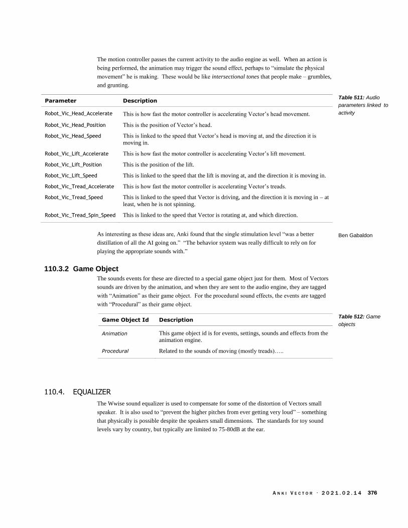
A N K I V E C T O R · 2 0 2 1 . 0 2 . 1 4 376
The motion controller passes the current activity to the audio engine as well. When an action is
being performed, the animation may trigger the sound effect, perhaps to “simulate the physical
movement” he is making. These would be like intersectional tones that people make – grumbles,
and grunting.
Parameter Description
Robot_Vic_Head_Accelerate This is how fast the motor controller is accelerating Vector’s head movement.
Robot_Vic_Head_Position This is the position of Vector’s head.
Robot_Vic_Head_Speed This is linked to the speed that Vector’s head is moving at, and the direction it is
moving in.
Robot_Vic_Lift_Accelerate This is how fast the motor controller is accelerating Vector’s lift movement.
Robot_Vic_Lift_Position This is the position of the lift.
Robot_Vic_Lift_Speed This is linked to the speed that the lift is moving at, and the direction it is moving in.
Robot_Vic_Tread_Accelerate This is how fast the motor controller is accelerating Vector’s treads.
Robot_Vic_Tread_Speed This is linked to the speed that Vector is driving, and the direction it is moving in – at
least, when he is not spinning.
Robot_Vic_Tread_Spin_Speed This is linked to the speed that Vector is rotating at, and which direction.
As interesting as these ideas are, Anki found that the single stimulation level “was a better
distillation of all the AI going on.” “The behavior system was really difficult to rely on for
playing the appropriate sounds with.”
110.3.2 Game Object
The sounds events for these are directed to a special game object just for them. Most of Vectors
sounds are driven by the animation, and when they are sent to the audio engine, they are tagged
with “Animation” as their game object. For the procedural sound effects, the events are tagged
with “Procedural” as their game object.
Game Object Id Description
Animation This game object id is for events, settings, sounds and effects from the
animation engine.
Procedural Related to the sounds of moving (mostly treads)…..
110.4. EQUALIZER
The Wwise sound equalizer is used to compensate for some of the distortion of Vectors small
speaker. It is also used to “prevent the higher pitches from ever getting very loud” – something
that physically is possible despite the speakers small dimensions. The standards for toy sound
levels vary by country, but typically are limited to 75-80dB at the ear.
Table 511: Audio
parameters linked to
activity
Ben Gabaldon
Table 512: Game
objects

A N K I V E C T O R · 2 0 2 1 . 0 2 . 1 4 377
110.5. THE CONFIGURATION
The audio configuration and sound files are located in:
/anki/data/assets/cozmo_resources/ sound
There are three kinds of files located there: configuration files, sound bank files (which may
include sounds), and sound files.
110.5.1 The configuration files
These configuration file is
/anki/data/assets/cozmo_resources/sound/ SoundbankBundleInfo.json
This file name is hard coded into libaudio_engine. The file is n array of structures, each with the
following fields:
Field Type Description & Notes
bundle_name string A name?
language string “SFX” or “English(US)” (It isn’t clear how to interpret these.
path string The path of the sound bank file, relative to the location of the
configuration file.
soundbank_name string The name of the sound bank file, without the “.bnk” extension.
110.6. THE SOUND FILES
The concepts above are held within a network of sound bank and WEM files, starting with the
JSON configuration file which specifies the bank files to load:
Soundbank
BundleInfo.jsonInit
Victor_UI
Victor_VO
Victor_Global_Data
Victor_SFXVictor_Alexa Victor_Dev
WEM FileWEM File WEM FileWEM File WEM FileWEM File
110.6.1 Sound Bank Files (BNK)
A sound bank is a binary file, composed of series tagged sections. Some sections are
The sound bank file has setups for how the sounds flow from files (and other inputs), thru
mixers, and other filters to the output. It calls this the audio bus hierarchy.
Sound effects,
Music compositions to play, (these probably are used heavily in Cozmo, but appear unused
in Vector)
State transition management, how altering the settings of effects during play.
Table 513: The sound
bank bundle info
JSON structure
Figure 113: The
relationship between
sound banks and
WEM files
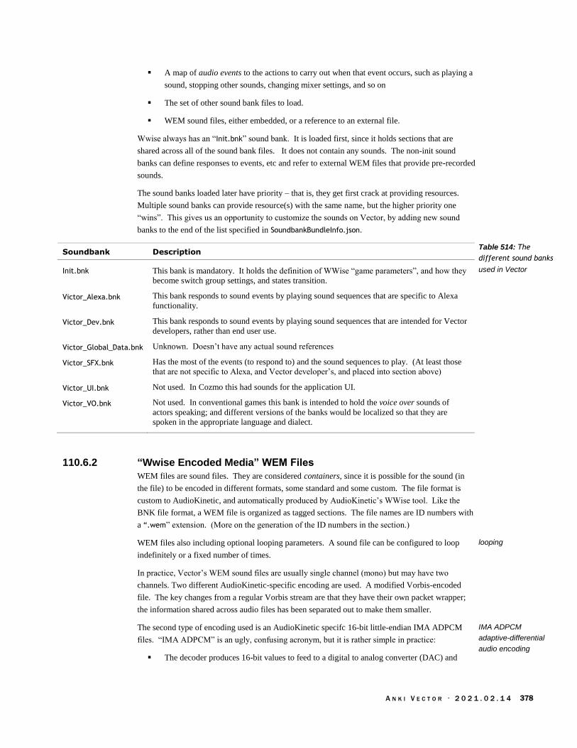
A N K I V E C T O R · 2 0 2 1 . 0 2 . 1 4 378
A map of audio events to the actions to carry out when that event occurs, such as playing a
sound, stopping other sounds, changing mixer settings, and so on
The set of other sound bank files to load.
WEM sound files, either embedded, or a reference to an external file.
Wwise always has an “Init.bnk” sound bank. It is loaded first, since it holds sections that are
shared across all of the sound bank files. It does not contain any sounds. The non-init sound
banks can define responses to events, etc and refer to external WEM files that provide pre-recorded
sounds.
The sound banks loaded later have priority – that is, they get first crack at providing resources.
Multiple sound banks can provide resource(s) with the same name, but the higher priority one
“wins”. This gives us an opportunity to customize the sounds on Vector, by adding new sound
banks to the end of the list specified in SoundbankBundleInfo.json.
Soundbank Description
Init.bnk This bank is mandatory. It holds the definition of WWise “game parameters”, and how they
become switch group settings, and states transition.
Victor_Alexa.bnk This bank responds to sound events by playing sound sequences that are specific to Alexa
functionality.
Victor_Dev.bnk This bank responds to sound events by playing sound sequences that are intended for Vector
developers, rather than end user use.
Victor_Global_Data.bnk Unknown. Doesn’t have any actual sound references
Victor_SFX.bnk Has the most of the events (to respond to) and the sound sequences to play. (At least those
that are not specific to Alexa, and Vector developer’s, and placed into section above)
Victor_UI.bnk Not used. In Cozmo this had sounds for the application UI.
Victor_VO.bnk Not used. In conventional games this bank is intended to hold the voice over sounds of
actors speaking; and different versions of the banks would be localized so that they are
spoken in the appropriate language and dialect.
110.6.2 “Wwise Encoded Media” WEM Files
WEM files are sound files. They are considered containers, since it is possible for the sound (in
the file) to be encoded in different formats, some standard and some custom. The file format is
custom to AudioKinetic, and automatically produced by AudioKinetic’s WWise tool. Like the
BNK file format, a WEM file is organized as tagged sections. The file names are ID numbers with
a “.wem” extension. (More on the generation of the ID numbers in the section.)
WEM files also including optional looping parameters. A sound file can be configured to loop
indefinitely or a fixed number of times.
In practice, Vector’s WEM sound files are usually single channel (mono) but may have two
channels. Two different AudioKinetic-specific encoding are used. A modified Vorbis-encoded
file. The key changes from a regular Vorbis stream are that they have their own packet wrapper;
the information shared across audio files has been separated out to make them smaller.
The second type of encoding used is an AudioKinetic specifc 16-bit little-endian IMA ADPCM
files. “IMA ADPCM” is an ugly, confusing acronym, but it is rather simple in practice:
The decoder produces 16-bit values to feed to a digital to analog converter (DAC) and
Table 514: The
different sound banks
used in Vector
looping
IMA ADPCM
adaptive-differential
audio encoding

A N K I V E C T O R · 2 0 2 1 . 0 2 . 1 4 379
the amplifier and speaker; that is the pulse code modulation (PCM) portion.
The sound file only has 4 bit values for each sample. Each 4 bit value is used as the index
into a pair of look up tables for how much to add to or subtract from the previous 16-bit
value for the new output; this is the adaptive differential (AD) portion.
The tables and their interpretation are standardized by a committee, which is the IMA
portion.
This approach is easy for the processor, and takes little working memory. It does make for larger
files than, say, MP3 or other more sophisticated compression. That is acceptable since the sound
segments are all short, and Vector has a large storage area to hold the files.
This approach has one drawback. It uses only 4 bits in each sample to represent the change in the
analog waveform. Often this isn’t enough; it takes several samples to add or subtract enough for
the output to catch up to the desired values (from the source material). At “low” sample rates, this
can create audible distortion. The fix is to use a higher sample rate for encoding. First, there is
less change between two points closer together in time. Second, the higher rate lets the decoder
catch up faster; this effectively makes the distortion at high, inaudible frequencies. The play back
can be done with this higher sample rate, or it can be down-sampled again after decoding.
Vector (probably) down-samples many of the sound files (after decoding) during playback. The
audio files have sample rates much higher than is supported through the SDK audio channels:
many at 30,000 samples/sec, some as high as 44,100 sample/sec.
110.6.3 Wave files
The audio engine includes a facility to load wave files for sound (so long as they are RIFF with
PCM data). It likely it was added in preparation for the “messaging” feature. A message from a
friend could be recorded, and distributed to a particular Vector. vic-engine could trigger the
playback of the audio by vic-anim.
110.7. MAPPING AUDIO EVENT AND SOUND NAMES TO ID NUMBERS
The ID number used to identify the events and audio files is not random or entirely arbitrary. It
is formed from the text names used by sound engineers and software developers. The number is
automatically made from the text names of the events and sound by the AudioKinetic software50
using a Fowler-Noll-Vo hash function. (The number is used instead of strings to reduce runtime
memory and processing overhead during game play.)
The algorithm to compute the 32-bit hash number:
1. “Start with an initial hash value of FNV offset basis.” (Use 16777619 for this offset)
2. “For each [character] in the input,
a. “multiply [the] hash by the FNV prime,” (use 2166136261 for the prime.)
b. convert the next character to lower case
c. XOR the hash with the lower case character
50 https://www.audiokinetic.com/library/edge/?source=SDK&id=_ak_f_n_v_hash_8h_source.html
IDs from names
Fowler-Noll-Vo hash

A N K I V E C T O R · 2 0 2 1 . 0 2 . 1 4 380
111. TEXT TO SPEECH
Vector includes a text to speech (TTS) facility. The engine is based on Cozmo’s text-to-speech
subsystem, with the text-to-speech engine from Acapela. The text to speech engine is part of vic-
anim, with some components in libcozmo_engine. Vector treats the process of speaking as a type
of animation, one with just an audio track. The audio for the speech is generated, and then handled
by the animation manager.51
The text-to-speech voices are stored in
/anki/data/assets/cozmo_resources/tts
The voice files include:
co-French-Bruno-22khz
co-German-Klaus-22khz
co-Japanese-Sakura-22khz
co-USEnglish-Bendnn-22khz
111.1. THAT DISTINCT ROBOTIC VOICE QUALITY
The text to speech engine produces human-sounding speech… so how does it get to be Vector’s
robotic voice? The audio is pumped through a vocoder (the Krotos Dehumaniser) in the sound
engine to give it a distinct sound.
Rest of
audio
engine
Pitch
Tracker
Multi-band
Equalizer
30ms
segmentation
Text To
Speech
The exact implementation isn’t known, but there are common techniques. A typical vocoder works
by estimating the pitch of the text-to-speech voice every 30ms, and then adjusting the gains
settings on a multi-band equalizer.
111.1.1 Pitch tracker
Krotos’ pitch detection – or pitch tracker – can be configured to use one five different algorithms:
1. Autocorrelation
2. Cepstrum
3. McLeod pitch detection method (MPM)
4. Frequency spectrum-based
5. YIN
51 https://forums.anki.com/t/multiple-actions-possibility-for-sdk/104
text to speech
Duhmaniser vocoder
Figure 114: High-level
vocoder functional
flow
pitch tracking
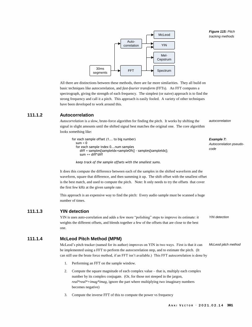
A N K I V E C T O R · 2 0 2 1 . 0 2 . 1 4 381
30ms
segmentsFFT Spectrum
Mel-
Cepstrum
Auto-
correlation YIN
McLeod
All there are distinctions between these methods, there are far more similarities. They all build on
basic techniques like autocorrelation, and fast-fourier transform (FFTs). An FFT computes a
spectrograph, giving the strength of each frequency. The simplest (or naive) approach is to find the
strong frequency and call it a pitch. This approach is easily fooled. A variety of other techniques
have been developed to work around this.
111.1.2 Autocorrelation
Autocorrelation is a slow, brute-force algorithm for finding the pitch. It works by shifting the
signal in slight amounts until the shifted signal best matches the original one. The core algorithm
looks something like:
for each sample offset (1... to big number) sum = 0 for each sample index 0...num samples diff = samples[sampleIdx+sampleOfs] - samples[sampleIdx]; sum += diff*diff keep track of the sample offsets with the smallest sums.
It does this compute the difference between each of the samples in the shifted waveform and the
waveform, square that difference, and then summing it up. The shift offset with the smallest offset
is the best match, and used to compute the pitch. Note: It only needs to try the offsets that cover
the first few kHz at the given sample rate.
This approach is an expensive way to find the pitch: Every audio sample must be scanned a huge
number of times.
111.1.3 YIN detection
YIN is uses auto-correlation and adds a few more “polishing” steps to improve its estimate: it
weights the different offsets, and blends together a few of the offsets that are close to the best
one.
111.1.4 McLeod Pitch Method (MPM)
McLeod’s pitch tracker (named for its author) improves on YIN in two ways. First is that it can
be implemented using a FFT to perform the autocorrelation step, and to estimate the pitch. (It
can still use the brute force method, if an FFT isn’t available.) This FFT autocorrelation is done by
1. Performing an FFT on the sample window.
2. Compute the square magnitude of each complex value – that is, multiply each complex
number by its complex conjugate. (Or, for those not steeped in the jargon,
real*real*+imag*imag, ignore the part where multiplying two imaginary numbers
becomes negative)
3. Compute the inverse FFT of this to compute the power vs frequency
Figure 115: Pitch
tracking methods
autocorrelation
Example 7:
Autocorrelation pseudo-
code
YIN detection
McLeod pitch method

A N K I V E C T O R · 2 0 2 1 . 0 2 . 1 4 382
4. Identify the frequency with the highest power associated with it
McLeod’s method, adds a few more polishing steps as well to clean this up and mix together a few
of the best results to get a better one.
111.1.5 Mel Cepstrum
The Mel Cepstrum method is similar to the FFT-base auto correlation, but tweaked to take into
account the psychology of pitch:
1. Performing an FFT on the sample window.
2. Compute the square magnitude of each complex value
3. Change from frequency (Hz) to “mel scale”,’ which is a perceptual scale for pitch
4. Compute the logs of all of those numbers on this scale
5. Compute a discrete cosine transform of this to compute the amplitude vs frequency
6. Identify the frequency with the highest amplitude associated with it
111.2. THE CONFIGURATION AND LOCALIZATION FILES
The configuration file for the text to speech engine is located at:
/anki/data/assets/cozmo_resources/ config/engine/tts_config.json
(This path is hardcoded into vic-anim.) This file is organized as dictionary whose key is the
operating system. The “vicos” key is the one relevant for Vector.52 This dereferences to a
dictionary whose key is the language base: “de”, “en”, “fr”, or “ja”. The language dereferences to
a structure with the following fields:
Field Type Description & Notes
pitch float This is a pitch setting field. This is not supported by all voices /
platforms. (The comment says that this is Acapela TTS SDK.)
“Pitch… adjustment is actually performed by audio layer.”
Optional.
shaping optional
speed float
speedTraits speedTraits[] Array of speed traits structures (see below). Optional
voice string a path to the ini file within the [assets/cozmo_resources/tts]
folder
Each speedTraits structure has the following fields:
Field Type Description & Notes
rangeMax uint
rangeMin uint
textLengthMax uint
textLengthMin uint
52 The other OS key is “osx” which suggests that Vector’s software was development on an OS X platform.
Mel Cepstrum
Table 515: The JSON
structure
Table 516: The
speedTraits JSON
structure

A N K I V E C T O R · 2 0 2 1 . 0 2 . 1 4 383
111.2.1 Localization
Vector internally has support for German, French, and Japanese, but the application-level language
settings only really support US, UK, and Australian dialects of English. The files for non-English
localization were not completed.
The localization files for feature stores its text strings (to be spoken) in
/anki/data/assets/cozmo_resources/ LocalizedStrings
This path is not present in versions before v1.6. The folder holds sub-folders based on the
language:
de-DE en-US fr-FR
Note: there is no ja-JA, but it may be possible to create.
Inside of each are three files intended to provide the strings, for a behaviour, in the locale:
BehaviorStrings.json
BlackJackStrings.json
FaceEnrollmentStrings.json
Each JSON file is a dictionary with the following fields:
Field Type Description & Notes
smartling53 structure see below to the structure below. Note all smarting structures
examined are the same.
The dictionary also includes keys, such as “BehaviorDisplayWeather.Rain” that map to a locale
specific string. These have the following fields:
Field Type Description & Notes
translation string The text in the given locale. The string may have placeholders,
such as {0}, where text is substituted in.
Each smartling structure has the following fields:
Field Type Description & Notes
placeholder_format_custom array of strings An array of patterns that represent possible placeholder patterns.
source_key_paths array of strings “/{*}” Strings are path of a JSON key?
translate_paths array of strings “*/translation” Strings are path of a JSON key?
translate_mode string “custom”
variants_enabled boolean
This is handled by libcozmo_engine, including the key strings.
53 it really has this key.
Table 517: The JSON
structure
Table 518: The JSON
structure
Table 519: The JSON
structure

A N K I V E C T O R · 2 0 2 1 . 0 2 . 1 4 384
WEATHER FILES
The weather behaviour stores its text strings (to be spoken) in
/anki/data/assets/cozmo_resources/ config/engine/behaviorComponent/weather/conditi
on_to_tts.json
This path is hardcoded into libcozmo_engine. The JSON file is an array of structures. Each
structure has the following fields:54
Field Type Description & Notes
Condition string e.g. “Cloudy”, “Cold”
Say string The key used in the BehaviorStrings.json file to look up the
localized test. (In previous versions, this was the text to say, in
English.)
111.3. CUSTOMIZATION
Vector’s voice files are from Acapela. Acapela sells language packs for book readers, but the
format appears different and likely very difficult to modify or create.
Cozmo’s employs a different English voice (in the Cozmo APK). This likely could be extracted
and used on Vector. (In turn, Vectors voice could probably be used with Cozmo.)
Customization of the Localization TTS would give Vector a bit more personality.
112. COMMANDS
The HTTPS SDK API (Chapter 15) includes commands that affect the sounds
Audio stream commands (see Chapter 15 section 50.6 External Audio Stream Playback)
Text to speech (see Chapter 15 section 50.8 Say Text) An external application can direct
Vector to speak using the Say Text command. The response(s) provide status of where
Vector is in the speaking process.
Vector’s volume can be set as a setting using the UpdateSettings command (see Chapter 15
section 66.2 Update Settings) and the RobotSettingsConfig structure (see chapter 31), or
using the Master Volume command (see Chapter 15 section 50.7 Master Volume). Note:
the volume levels using settings doesn’t fully match those in the master volume command.
Note: can also trigger animations which play sounds effects as well.
113. REFERENCES AND RESOURCES
AudioKinetic , Wwise Fundamentals (2015)
https://www.audiokinetic.com/download/documents/Wwise_Fundamentals.pdf
AudioKinetic, Wwise User’s Guide
https://www.audiokinetic.com/files/?get=2015.1.9_5624/Wwise_UserGuide_en.pdf
AudioKinetic, The Wwise Project Adventure
https://www.audiokinetic.com/download/documents/WwiseProjectAdventure_en.pdf
54 That this file (and many others) is a simple 1:1 transform lends the suspicion that the localization process is needlessly complex.
Table 520: The JSON
structure

A N K I V E C T O R · 2 0 2 1 . 0 2 . 1 4 385
AudioKinetic, Get Started Using Wwise
https://www.audiokinetic.com/download/documents/Wwise_GetStartedGuide.pdf
AudioKinetic, Wwise 101
https://www.audiokinetic.com/download/lessons/wwise101_en.pdf
AudioKinetic, Wwise Fundamentals, Understanding Events
https://www.audiokinetic.com/library/edge/?source=WwiseFundamentalApproach&id=under
standing_events_understanding_events
Cheveigne, Alain de. (2002). “YIN, a fundamental frequency estimator for speech and music,”
Journal of the Acoustical Society of America. Vol 111(4), pp 1917-30.
http://audition.ens.fr/adc/pdf/2002_JASA_YIN.pdf
Coull, Ashley, Sound for Robots: An Interview with Sr. Sound Designer Ben Gabaldon, 2016 Nov
15, Designing Sound
http://designingsound.org/2016/11/15/sound-for-robots-an-interview-with-sr-sound-designer-
ben-gabaldon/
Krotos, Dehumaniser Live
https://www.krotosaudio.com/dehumaniser-live/
https://www.krotosaudio.com/products/dehumaniser2/
https://s3-us-west-2.amazonaws.com/dehumaniser/Manuals/Dehumaniser+2+Manual.pdf
Krotos, Dehumaniser Live, Integration With Wwise, 2017
https://s3-us-west-
2.amazonaws.com/dehumaniser/Manuals/Dehumaniser+Live+for+Wwise+Manual.pdf
Louis, Patrick. Making Sense of the Audio Stack On Unix,2021 Feb 7
https://venam.nixers.net/blog/unix/2021/02/07/audio-stack.html
McLeod, Philip and Wyvill, G., “A Smarter Way to Find Pitch” (2003), Proc. International
Computer Music Conference, Barcelona, Spain, September 5-9, 2005, pp 138-141.
http://miracle.otago.ac.nz/tartini/papers.html
Sweet, Michael, Creating Music for Robots: Interview with the Composing Team for Cozmo,
Design Music Now, 2016 Dec 12
https://www.designingmusicnow.com/2016/12/12/creating-music-robots-interview-
composing-team-cozmo/
Wikipedia, Cepstrum
https://en.m.wikipedia.org/wiki/Cepstrum
Wikipedia, Fowler-Noll-Vo hash function
https://en.wikipedia.org/wiki/Fowler%E2%80%93Noll%E2%80%93Vo_hash_function
Wikipedia, Mel-Frequency Cepstrum
https://en.m.wikipedia.org/wiki/Mel-frequency_cepstrum
Wikipedia, Mel scale
https://en.wikipedia.org/wiki/Mel_scale
Wikipedia, Pitch detection algorithms
https://en.wikipedia.org/wiki/Pitch_detection_algorithm
Wolford, Jason; Ben Gabaldon, Jordan Rivas, Brian Min Condition-Based Robots Audio
Techniques, Anki , USPTO Pub.No: US2019/0308327A1, 2018 Apr 6
Xentax, Wwise SoundBank (*.bnk), 2012 Dec 6
http://wiki.xentax.com/index.php/Wwise_SoundBank_(*.bnk)
This site provides a wealth of information on the format of the Sound Bank files.
Unfortunately not all sections of the file have been documented, and there are sections in
Vector’s Sound Bank files that were not known when this page was written
Some example code for YIN and McLeod pitch tracking
https://github.com/ashokfernandez/Yin-Pitch-Tracking
https://github.com/adamski/pitch_detector/blob/master/source/PitchMPM.h
https://github.com/sevagh/pitch-detection/blob/master/src/mpm.cpp

A N K I V E C T O R · 2 0 2 1 . 0 2 . 1 4 386
CHAPTER 26
Motion Control
This chapter describes the motion control subsystem:
The control of the motors
Performing head and lift movements
Moving along paths in a smooth and controlled fashion
Note: the motion control is implemented in vic-robot (except where stated otherwise, of course)
114. MOTION CONTROL
The motion control is designed to take a path of movements from the path planner or the animation
systems. The path consists of arc, line, and turn (in place) movement commands. These can be
coordinated with the head and lift, by the animation system.
Note: the animation system is described in chapter 22
Head
Path
· Turn in place
· Lines
· Arcs
Lift
LiftControllerHead
Controller
Wheel
Controller
Steering
Controller
Path
Follower
Mobile App
& Python
SDK
applications
Vic-GatewayVic-Anim
Action
Controller
The individual motors have controllers to calibrate, move, prevent motor burnout, and perform any
special movements.
114.1. PATHS
The path planner thinks of the world and robot coordinates within it in terms of x,y and θ (theta)
coordinates. The θ being the direction angle that Vector is facing at the time. It builds a list of
Figure 116: Motion
controller

A N K I V E C T O R · 2 0 2 1 . 0 2 . 1 4 387
straight line segments, arcs, and point turns. Each of the motors is independently driven and
controlled, with the steering controller coordinating the driving actions.
The PathFollower carries out the driving plan. It receives a list of driving segments. Each segment
has an associated speed, acceleration, and deceleration to drive at. The three kinds of segments
are:
Drive in a straight line
Drive arcs
Turn in place
When it receives the list, it checks that certain rules are followed.
The list is not too long
That each segment type is known
That the path is continuous: the end-point of one segment must be the same as the starting
point of the next segment.
114.2. FEEDBACK
The motion controller may take position and orientation feedback from
The linear speed can be estimated from the motors shaft rotation speed (and some
estimated tread slip), merged with IMU information
The speed that the robot is rotating can be measured by the IMU and the vision system.
The navigation and localization subsystem, which employs a sophisticated Kalman filter
on all of the above position.
114.3. MOTOR CONTROL
Vector’s small, light frame and powerful (for their size) motors allow him to make quick actions
representing his emotions and little tantrums, as well as drive about smoothly. A typical speed and
position controller for the brushed DC motors is a set of PID control loops. (Although the “d” –
derivative – term is often small or unneeded.)
Position
Motor driver
Speed
PID
Controller
Encoder
Motor
Speed filter
Position
PID
ControllerPosition & Speed
or Speed
Limiter
Body-Board controllerHead-Board controller
The motor control loops are implemented in the head-board. They are implemented using floating
point (rather than the fixed point55 that the body-board’s M0 microcontroller would require), and
55 Although both approaches work, fixed point (using integers and scaling factors rather than floating point) takes a bit more effort to
tune, as small but important parts of the feedback signals are dropped… this can introduce effects like jerkiness, stutter or motor noise from.
Figure 117: A typical
motor control loops, as
they might appear in
Vector
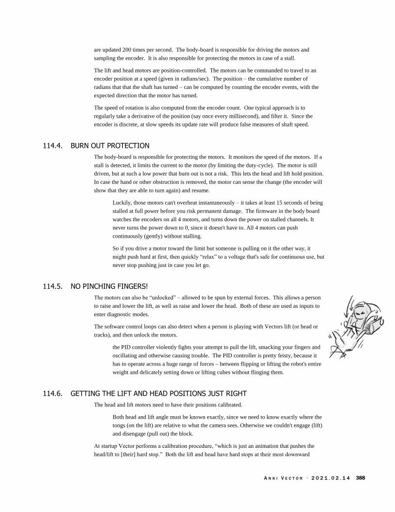
A N K I V E C T O R · 2 0 2 1 . 0 2 . 1 4 388
are updated 200 times per second. The body-board is responsible for driving the motors and
sampling the encoder. It is also responsible for protecting the motors in case of a stall.
The lift and head motors are position-controlled. The motors can be commanded to travel to an
encoder position at a speed (given in radians/sec). The position – the cumulative number of
radians that that the shaft has turned – can be computed by counting the encoder events, with the
expected direction that the motor has turned.
The speed of rotation is also computed from the encoder count. One typical approach is to
regularly take a derivative of the position (say once every millisecond), and filter it. Since the
encoder is discrete, at slow speeds its update rate will produce false measures of shaft speed.
114.4. BURN OUT PROTECTION
The body-board is responsible for protecting the motors. It monitors the speed of the motors. If a
stall is detected, it limits the current to the motor (by limiting the duty-cycle). The motor is still
driven, but at such a low power that burn out is not a risk. This lets the head and lift hold position.
In case the hand or other obstruction is removed, the motor can sense the change (the encoder will
show that they are able to turn again) and resume.
Luckily, those motors can't overheat instantaneously – it takes at least 15 seconds of being
stalled at full power before you risk permanent damage. The firmware in the body board
watches the encoders on all 4 motors, and turns down the power on stalled channels. It
never turns the power down to 0, since it doesn't have to. All 4 motors can push
continuously (gently) without stalling.
So if you drive a motor toward the limit but someone is pulling on it the other way, it
might push hard at first, then quickly “relax” to a voltage that's safe for continuous use, but
never stop pushing just in case you let go.
114.5. NO PINCHING FINGERS!
The motors can also be “unlocked” – allowed to be spun by external forces. This allows a person
to raise and lower the lift, as well as raise and lower the head. Both of these are used as inputs to
enter diagnostic modes.
The software control loops can also detect when a person is playing with Vectors lift (or head or
tracks), and then unlock the motors.
the PID controller violently fights your attempt to pull the lift, smacking your fingers and
oscillating and otherwise causing trouble. The PID controller is pretty feisty, because it
has to operate across a huge range of forces – between flipping or lifting the robot's entire
weight and delicately setting down or lifting cubes without flinging them.
114.6. GETTING THE LIFT AND HEAD POSITIONS JUST RIGHT
The head and lift motors need to have their positions calibrated.
Both head and lift angle must be known exactly, since we need to know exactly where the
tongs (on the lift) are relative to what the camera sees. Otherwise we couldn't engage (lift)
and disengage (pull out) the block.
At startup Vector performs a calibration procedure, “which is just an animation that pushes the
head/lift to [their] hard stop.” Both the lift and head have hard stops at their most downward

A N K I V E C T O R · 2 0 2 1 . 0 2 . 1 4 389
position, which serves a well-defined starting point. When these motors reach the end of travel,
the measured speed will fall below a threshold, and the software knows to zero estimated position.
Vector’s software has two backups in case the position is wrong. This can happen if the calibration
was wrong – something, perhaps a block or impatient human companion – prevented the head or
lift from moving further. Or if someone moved his lifts or head (since the position encoder is single
step, Vector won’t be able to tell which direction they were moved).
1. The body-board firmware has motor burnout prevent features. This quickly drops the
power applied to the motor if there is a stall.
2. If a motor is stalled unexpectedly or the motor isn’t stopped (by the hard stop) within 5%
of where it should, Vector schedules another calibration procedure. (This is handled by the
ReactToUncalibratedHeadAndLift behavior.)
114.7. DIFFERENTIAL DRIVE KINEMATICS
Under ideal circumstances, these motions are straight-forward to accomplish:
To turn in place, the treads turn at the same rate, but in opposite directions. The speed of
the turn is proportional to the speed of treads
To drive straight, both treads turn at the same speed. The speed of motion is proportional
to the speed of the treads.
To drive in an arc is done by driving the treads at two different speeds.
To drive in an arc, the left and right treads are driven speeds:
widthradiusv
widthradiusv
right
left
21
21
Where
width is Vector’s body width
ω is the angular velocity, i.e. speed to drive around the arc
radius is the distance from the center of the arc to the center of Vector’s body:
radius
114.7.1 Slip
In practice, Vector’s actual movement won’t quite match what he attempted to do. Mainly this will
come from how the treads slip a bit (especially while trying to push an object), and some variation
in how driving the motors maps to actual motion.
Equation 3: Tread
speeds based on arc
radius
Figure 118: Radius of
arc measurement

A N K I V E C T O R · 2 0 2 1 . 0 2 . 1 4 390
115. MOTION CONTROL COMMANDS
The HTTPS SDK API (Chapter 15) includes commands to control the motors, and to initiate
driving actions. The lower level commands, below the action processor are:
Drive Wheels
Move Head
Move Lift
Stop All Motors
The higher level commands, part of the action system are:
Drive Straight
Stop All Motors
Turn In Place
Set Head Angle
Set Lift Height
Go to Pose
Turn Towards face
Go To Object

A N K I V E C T O R · 2 0 2 1 . 0 2 . 1 4 391
CHAPTER 27
Animation File Format
The binary animation files are the most significant of Vector’s animation files. The file format
provides for coordinating the display, motion, and sound responses.
Animation file format overview
Structures in the file
116. ANIMATION BINARY FILE FORMAT
The schema and format of the animation binary file is given as a flatbuffer specification. This
specification is located at:
/anki/data/assets/cozmo_resources/config/ cozmo_anim.fbs
Note: this file is not read by any program in Vector. A compatible parser is compiled in.
116.1. OVERVIEW OF THE FILE FORMAT
The animation file contains one or more named animation “clips.” Each clip has one or more
tracks that represent the scripted motions (and lights & sounds) that Vector should perform. There
are tracks for moving Vector’s head, lift, driving, modifying his facial expressions, displaying
images on the LCD, audio effects, and controlling the backpack lights.
Backpack
Lights
Motion Control
· Head angle
· Lift height
· Turn in place
· Driving
Events
Key frames
Sprite
sequences
Sound
files &
parametric
sounds
Procedural
Face Controller
· Face tilt
· Eye controls
Named
Animation
clips
Named
Animation
clips
Named
Animation
clips
Name
Each of the tracks within the clip is composed of key frames (with settings for each of the relevant
tracks) that are triggered at different points in time.
116.2. RELATIONSHIP WITH COZMO
Vector’s file format for animations is derived from the file format used with Cozmo. This presents
the possibility of adapting Cozmo’s animation files to Vector, and vice-versa. The code generated
Figure 119: The
animation file structure

A N K I V E C T O R · 2 0 2 1 . 0 2 . 1 4 392
by Google’s flatbuffer tools ignores extra fields, and assigns default values to missing ones. This
makes it possible to use a Cozmo animation file with Vector – accepting that some areas, such as
the sounds, won’t link up fully. The key differences between Cozmo and Vector’s formats are that
Vector includes audio tracks, plus some minor extra fields, and fewer backlight LEDs.
The PyCozmo project has the (experimental) ability extract Cozmo’s animations, and may be
useful for this transcoding and adjustment to Vector’s aesthetic.
117. STRUCTURES
The animation file starts with an AnimClips structure. Unless specified otherwise, each structure is
the same as in Cozmo.
By default, all fields are optional unless specified otherwise.
117.1. ANIMCLIPS
The AnimClips structure is the “root” type for the file. It provides one or more animation “clips” in
the file. Each clip has one or more tracks. The structure following fields:
Field Type Description
clips AnimClip[] An array of animation clips
117.2. ANIMCLIP
The AnimClip is a named animation that can be played. This structure has the following fields:
Field Type Description
Name string The name of the animation clip; this is also called the
animation trigger name.
keyframes Keyframes The key frames for each of the tracks for this animation clip
117.3. AUDIOEVENTGROUP
The AudioEventGroup structure is used to randomly select an audio event (and volume), and send it
to the audio subsystem. See Chapter 25, section 110.2 Audio Pipeline for a description of audio
events. This structure has the following fields:
Field Type Units Description
eventIds uint[] The audio event IDs, weighted by a probability.
volumes float[] The volume to play the selected audio at.
probabilities float[] (0..1] The probability weight that a given event will be selected.
This structure is new to Vector.
Table 521: AnimClips
structure
Table 522: AnimClip
structure
Table 523:
AudioEventGroup
structure
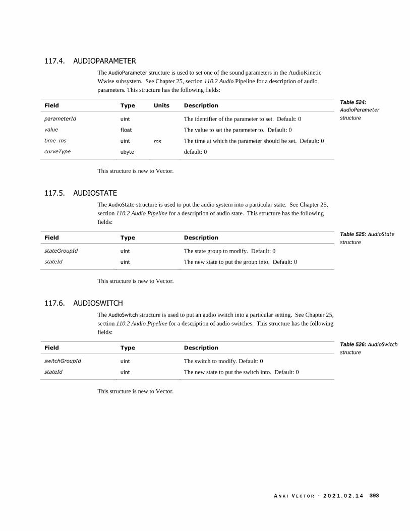
A N K I V E C T O R · 2 0 2 1 . 0 2 . 1 4 393
117.4. AUDIOPARAMETER
The AudioParameter structure is used to set one of the sound parameters in the AudioKinetic
Wwise subsystem. See Chapter 25, section 110.2 Audio Pipeline for a description of audio
parameters. This structure has the following fields:
Field Type Units Description
parameterId uint The identifier of the parameter to set. Default: 0
value float The value to set the parameter to. Default: 0
time_ms uint ms The time at which the parameter should be set. Default: 0
curveType ubyte default: 0
This structure is new to Vector.
117.5. AUDIOSTATE
The AudioState structure is used to put the audio system into a particular state. See Chapter 25,
section 110.2 Audio Pipeline for a description of audio state. This structure has the following
fields:
Field Type Description
stateGroupId uint The state group to modify. Default: 0
stateId uint The new state to put the group into. Default: 0
This structure is new to Vector.
117.6. AUDIOSWITCH
The AudioSwitch structure is used to put an audio switch into a particular setting. See Chapter 25,
section 110.2 Audio Pipeline for a description of audio switches. This structure has the following
fields:
Field Type Description
switchGroupId uint The switch to modify. Default: 0
stateId uint The new state to put the switch into. Default: 0
This structure is new to Vector.
Table 524:
AudioParameter
structure
Table 525: AudioState
structure
Table 526: AudioSwitch
structure
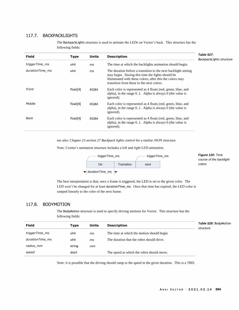
A N K I V E C T O R · 2 0 2 1 . 0 2 . 1 4 394
117.7. BACKPACKLIGHTS
The BackpackLights structure is used to animate the LEDs on Vector’s back. This structure has the
following fields:
Field Type Units Description
triggerTime_ms uint ms The time at which the backlights animation should begin.
durationTime_ms uint ms The duration before a transition to the next backlight setting
may begin. During this time the lights should be
illuminated with these colors; after this the colors may
transition from these to the next colors.
Front float[4] RGBA Each color is represented as 4 floats (red, green, blue, and
alpha), in the range 0..1. Alpha is always 0 (the value is
ignored).
Middle float[4] RGBA Each color is represented as 4 floats (red, green, blue, and
alpha), in the range 0..1. Alpha is always 0 (the value is
ignored).
Back float[4] RGBA Each color is represented as 4 floats (red, green, blue, and
alpha), in the range 0..1. Alpha is always 0 (the value is
ignored).
see also: Chapter 23 section 27 Backpack lights control for a similar JSON structure.
Note: Cozmo’s animation structure includes a left and right LED animation.
On nextTransition
durationTime_ms
triggerTime_ms triggerTime_ms
The best interpretation is that, once a frame is triggered, the LED is set to the given color. The
LED won’t be changed for at least durationTime_ms. Once that time has expired, the LED color is
ramped linearly to the color of the next frame.
117.8. BODYMOTION
The BodyMotion structure is used to specify driving motions for Vector. This structure has the
following fields:
Field Type Units Description
triggerTime_ms uint ms The time at which the motion should begin
durationTime_ms uint ms The duration that the robot should drive.
radius_mm string mm
speed short The speed at which the robot should move.
Note: it is possible that the driving should ramp to the speed in the given duration. This is a TBD.
Table 527:
BackpackLights structure
Figure 120: Time
course of the backlight
colors
Table 528: BodyMotion
structure

A N K I V E C T O R · 2 0 2 1 . 0 2 . 1 4 395
117.9. EVENT
The Event structure is used to pause the animation at the given time code until the event is received
or cancelled. When the event is received, the animation resumes the given time code. This
structure has the following fields:
Field Type Units Description
triggerTime_ms uint ms When the event occurs it triggers animation to begin at this
time.(?) Or, at this time, emit the event?
event_id string The name of the event.
The event names include
CHANGE_EYE_COLOR
CUBE_LIGHT_TOGGLE
DANCE_BEAT_SYNC
DEAL_CARDS_BEGIN
FLIP_DOWN_BEGIN
LISTENING_BEGIN
STRAIGHT
SWIPE_CARDS_BEGIN
TAPPED_BLOCK
TOGGLE_NUMBERS_DISPLAY
TURN_IN_PLACE
Note: unless otherwise specified the animations are not allowed to have event key frames – the
behavior wouldn’t expect to send the events to them.
117.10. FACEANIMATION
The FaceAnimation structure is used to specify the JSON file to animation Vector’s display. This
structure has the following fields:
Field Type Units Description
triggerTime_ms uint ms The time at which the motion is triggered.
animName string The time at the face animation should begin. See Chapter
24 section 105.6 Sprite Sequences. Required
scanlineOpacity float This is new for Vector. Default: 1.0
The scanlineOpacity is new to support Vector’s display. With Cozmo “the screen is displayed
interlaced, with only every other line displayed This alternates every time the image is changed
(no longer than 30 seconds) to prevent screen burn-in. Therefore to ensure the image looks correct
on either scan-line offset we use half the vertical resolution”
Table 529: Event
structure
Table 530:
FaceAnimation structure
Cozmo SDK (Anki)

A N K I V E C T O R · 2 0 2 1 . 0 2 . 1 4 396
117.11. HEADANGLE
The HeadAngle structure is used to specify how to move Vector’s head. The head should reach the
target angle in the duration given, ramping up the movement speed smoothly (with some
variability) until it reaches that that point. This structure has the following fields:
Field Type Units Description
triggerTime_ms uint ms The time at which the head motion should begin.
durationTime_ms uint ms How long the head motion should last.
angle_deg ubyte deg The angle to move the head to. This should be in the range -
22.0° to 45.0°.
angleVariability_deg ubyte deg The amount of randomness allowed for the target head
angle. Default: 0
117.12. LIFTHEIGHT
The LiftHeight structure is used to specify how to move Vector’s lift. The lift should reach the
target height in the duration given, ramping up the movement speed smoothly (with some
variability) until it reaches that. This structure has the following fields:
Field Type Units Description
triggerTime_ms uint ms The time at which the lift should begin motion.
durationTime_ms uint ms How long the lift motion should last.
height_mm ubyte mm The height to lift the arms to.
heightVariability_mm ubyte mm The amount of randomness allowed for the target height.
default: 0
Table 531: HeadAngle
structure
Table 532: LiftHeight
structure
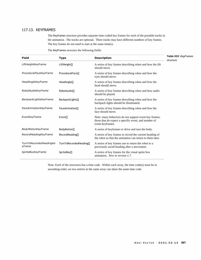
A N K I V E C T O R · 2 0 2 1 . 0 2 . 1 4 397
117.13. KEYFRAMES
The Keyframes structure provides separate time-coded key frames for each of the possible tracks in
the animation. The tracks are optional. There tracks may have different numbers of key frames.
The key frames do not need to start at the same time(s).
The KeyFrames structure the following fields:
Field Type Description
LiftHeightKeyFrame LiftHeight[] A series of key frames describing when and how the lift
should move.
ProceduralFaceKeyFrame ProceduralFace[] A series of key frames describing when and how the
eyes should move.
HeadAngleKeyFrame HeadAngle[] A series of key frames describing when and how the
head should move.
RobotAudioKeyFrame RobotAudio[] A series of key frames describing when and how audio
should be played.
BackpackLightsKeyFrame BackpackLights[] A series of key frames describing when and how the
backpack lights should be illuminated.
FaceAnimationKeyFrame FaceAnimation[] A series of key frames describing when and how the
face should move.
EventKeyFrame Event[] Note: many behaviors do not support event key frames;
those that do expect a specific event, and number of
event keyframes.
BodyMotionKeyFrame BodyMotion[] A series of keyframes to drive and turn the body.
RecordHeadingKeyFrame RecordHeading[] A series of key frames to record the current heading of
the robot so that the animation can return to them later.
TurnToRecordedHeadingKe
yFrame TurnToRecordedHeading[] A series of key frames use to return the robot to a
previously saved heading after a movement.
SpriteBoxKeyFrame SpriteBox[] A series of key frames for the visual sprite box
animation. New in version 1.7.
Note: Each of the structures has a time code. Within each array, the time code(s) must be in
ascending order; no two entries in the same array can share the same time code.
Table 533: KeyFrames
structure

A N K I V E C T O R · 2 0 2 1 . 0 2 . 1 4 398
117.14. PROCEDURALFACE
The ProceduralFace structure is used squash, stretch and shake Vectors face in cartoonish ways. It
does not affect where his eyes are focused. See Chapter 24 section 106 Procedural face for a
description of Vectors face, and how these parameters influence it. The structure has the following
fields:
Field Type Units Description
triggerTime_ms uint ms The time at which the motion is triggered.
faceAngle float default: 0
faceCenterX float default: 0
faceCenterY float default: 0
faceScaleX float default: 1.0
faceScaleY float default: 1.0
leftEye float[] If present, these describe modifications to the eye – lid,
cheeks, and shape of the eye. They have the structure given
below.
rightEye float[] If present, these describe modifications to the eye – lid,
cheeks, and shape of the eye. They have the structure given
below.
scanlineOpacity float This is new for Vector. default: 1.0
The arrays of floats for each eye in animations for Cozmo have been deciphered, and are
presumed to be the same for Vector. They are presumed to be the same for Vector:
Field Default Description
lower_inner_radius_x 0.5
lower_inner_radius_y 0.5
lower_outer_radius_x 0.5
lower_outer_radius_y 0.5
upper_inner_radius_x 0.5
upper_inner_radius_y 0.5
upper_outer_radius_x 0.5
upper_outer_radius_y 0.5
upper_lid_y 0.0 The vertical position of the upper eye lid (which occludes
the eye).
upper_lid_angle 0.0 The angle of the upper eye lid.
upper_lid_bend 0.0 The bend to the upper eye lid.
lower_lid_y 0.0 The vertical position of the lower eye lid / cheek (which
occludes the eye).
lower_lid_angle 0.0 The angle of the lower eye lid / cheek.
lower_lid_bend 0.0 The bend to the lower eye lid / cheek.
Table 534:
ProceduralFace
structure
PyCozmo
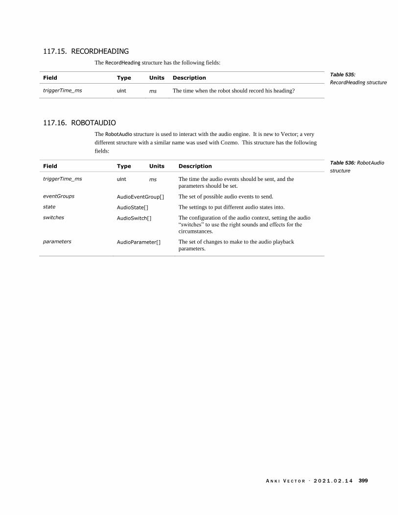
A N K I V E C T O R · 2 0 2 1 . 0 2 . 1 4 399
117.15. RECORDHEADING
The RecordHeading structure has the following fields:
Field Type Units Description
triggerTime_ms uint ms The time when the robot should record his heading?
117.16. ROBOTAUDIO
The RobotAudio structure is used to interact with the audio engine. It is new to Vector; a very
different structure with a similar name was used with Cozmo. This structure has the following
fields:
Field Type Units Description
triggerTime_ms uint ms The time the audio events should be sent, and the
parameters should be set.
eventGroups AudioEventGroup[] The set of possible audio events to send.
state AudioState[] The settings to put different audio states into.
switches AudioSwitch[] The configuration of the audio context, setting the audio
“switches” to use the right sounds and effects for the
circumstances.
parameters AudioParameter[] The set of changes to make to the audio playback
parameters.
Table 535:
RecordHeading structure
Table 536: RobotAudio
structure
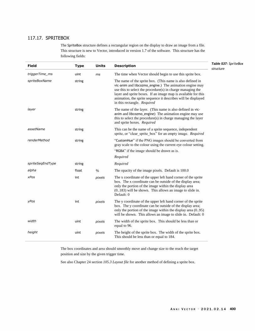
A N K I V E C T O R · 2 0 2 1 . 0 2 . 1 4 400
117.17. SPRITEBOX
The SpriteBox structure defines a rectangular region on the display to draw an image from a file.
This structure is new to Vector, introduced in version 1.7 of the software. This structure has the
following fields:
Field Type Units Description
triggerTime_ms uint ms The time when Vector should begin to use this sprite box.
spriteBoxName string The name of the sprite box. (This name is also defined in
vic-anim and libcozmo_engine.) The animation engine may
use this to select the procedure(s) in charge managing the
layer and sprite boxes. If an image map is available for this
animation, the sprite sequence it describes will be displayed
in this rectangle. Required
layer string The name of the layer. (This name is also defined in vic-
anim and libcozmo_engine) The animation engine may use
this to select the procedure(s) in charge managing the layer
and sprite boxes. Required
assetName string This can be the name of a sprite sequence, independent
sprite, or “clear_sprite_box” for an empty image. Required
renderMethod string “CustomHue” if the PNG images should be converted from
gray scale to the colour using the current eye colour setting.
“RGBA” if the image should be drawn as is.
Required
spriteSeqEndType string Required
alpha float % The opacity of the image pixels. Default is 100.0
xPos int pixels The x coordinate of the upper left hand corner of the sprite
box. The x coordinate can be outside of the display area;
only the portion of the image within the display area
(0..183) will be shown. This allows an image to slide in.
Default: 0
yPos int pixels The y coordinate of the upper left hand corner of the sprite
box. The y coordinate can be outside of the display area;
only the portion of the image within the display area (0..95)
will be shown. This allows an image to slide in. Default: 0
width uint pixels The width of the sprite box. This should be less than or
equal to 96.
height uint pixels The height of the sprite box. The width of the sprite box.
This should be less than or equal to 184.
The box coordinates and area should smoothly move and change size to the reach the target
position and size by the given trigger time.
See also Chapter 24 section 105.3 Layout file for another method of defining a sprite box.
Table 537: SpriteBox
structure
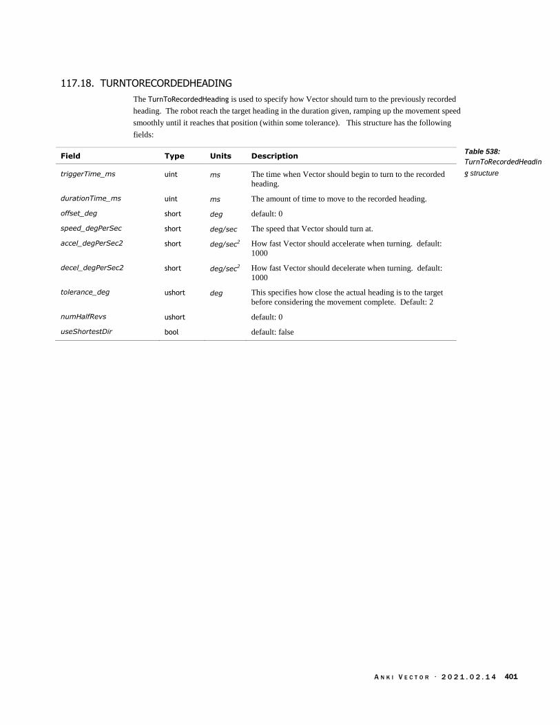
A N K I V E C T O R · 2 0 2 1 . 0 2 . 1 4 401
117.18. TURNTORECORDEDHEADING
The TurnToRecordedHeading is used to specify how Vector should turn to the previously recorded
heading. The robot reach the target heading in the duration given, ramping up the movement speed
smoothly until it reaches that position (within some tolerance). This structure has the following
fields:
Field Type Units Description
triggerTime_ms uint ms The time when Vector should begin to turn to the recorded
heading.
durationTime_ms uint ms The amount of time to move to the recorded heading.
offset_deg short deg default: 0
speed_degPerSec short deg/sec The speed that Vector should turn at.
accel_degPerSec2 short deg/sec2 How fast Vector should accelerate when turning. default:
1000
decel_degPerSec2 short deg/sec2 How fast Vector should decelerate when turning. default:
1000
tolerance_deg ushort deg This specifies how close the actual heading is to the target
before considering the movement complete. Default: 2
numHalfRevs ushort default: 0
useShortestDir bool default: false
Table 538:
TurnToRecordedHeadin
g structure

A N K I V E C T O R · 2 0 2 1 . 0 2 . 1 4 402
[This page is intentionally left blank for purposes of double-sided printing]

A N K I V E C T O R · 2 0 2 1 . 0 2 . 1 4 403
PART VI
High Level AI
This part describes items that are Vector’s behaviour function.
BEHAVIOR. A look at Vectors behaviors, and emotions
EMOTION MODEL. A look at how Vector emulates emotions
BEHAVIOR TREES. A look at how the behaviors are selected and their settings
drawing by Steph Dere

A N K I V E C T O R · 2 0 2 1 . 0 2 . 1 4 404
[This page is intentionally left blank for purposes of double-sided printing]

A N K I V E C T O R · 2 0 2 1 . 0 2 . 1 4 405
CHAPTER 28
Behavior
This chapter describes Vector’s action, behaviour, and emotion system:
Actions and behaviour queues
The emotion-behaviour system, and stimulation
118. OVERVIEW
How does Vector get excited from praise, and then decide to go exploring and play? How does he
decide it’s time to take a nap?
Vector’s high-level AI – his emotions, sense of the environment and himself, and behaviors – are a
key part of how he creates a compelling character. He has an emotional state that is seen in his
affect – his facial expression, head and arm posture – how he behaves and responds, as well as the
actions he initiates.
119. ACTIONS AND BEHAVIORS
Actions and “behaviors represent a complex task which requires Vector's internal logic to
determine how long it will take. This may include combinations of animation, path planning or
other functionality.”
119.1. ACTIONS AND THE ACTION QUEUES
Animations can be submitted with which tracks of the animation to disable. This allows multiple
actions can be run at the same time. If the action requires a track that is already in use, the action
isn’t run, and returns an error. Actions can automatically retry if a problem was encountered.
Actions can have associated “tag” used to refer to that running instance. The client can cancel the
action.
119.2. BEHAVIORS
Unlike actions, only one behavior can be active at a time. The others are waiting in a stack. A
behavior is submitted (to be run) with a priority; if its priority is higher priority the current one, it is
run instead. The old behavior is pushed down in the stack. When a behavior completes, the next
high priority one is resumed.
119.2.1 Priority Levels
The behaviors requested by Vector’s internal AI are submitted to the stack with a priority based on
that behavior. If the SDK has requested control, the behaviors it requests are submitted with the
priority level set when control was requested. As long as the SDK is connected and has control,
behaviors submitted at a lower priority will not activate, even if the SDK is not currently running a
behavior. The SDK can lose control if a higher priority is submitted (e.g. “like returning to the
charger due to low battery”), gives up control or closes the connection.
Anki SDK
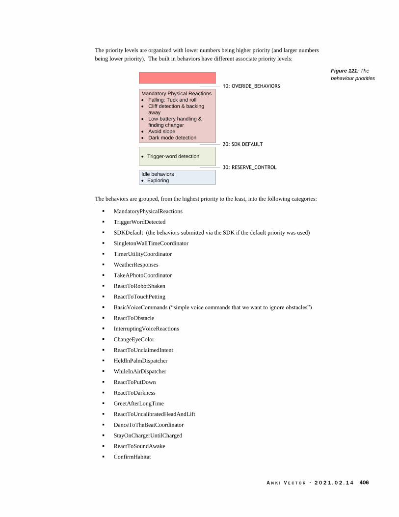
A N K I V E C T O R · 2 0 2 1 . 0 2 . 1 4 406
The priority levels are organized with lower numbers being higher priority (and larger numbers
being lower priority). The built in behaviors have different associate priority levels:
Mandatory Physical Reactions
· Falling: Tuck and roll
· Cliff detection & backing
away
· Low-battery handling &
finding changer
· Avoid slope
· Dark mode detection
Idle behaviors
· Exploring
· Trigger-word detection
30: RESERVE_CONTROL
20: SDK DEFAULT
10: OVERIDE_BEHAVIORS
The behaviors are grouped, from the highest priority to the least, into the following categories:
MandatoryPhysicalReactions
TriggerWordDetected
SDKDefault (the behaviors submitted via the SDK if the default priority was used)
SingletonWallTimeCoordinator
TimerUtilityCoordinator
WeatherResponses
TakeAPhotoCoordinator
ReactToRobotShaken
ReactToTouchPetting
BasicVoiceCommands (“simple voice commands that we want to ignore obstacles”)
ReactToObstacle
InterruptingVoiceReactions
ChangeEyeColor
ReactToUnclaimedIntent
HeldInPalmDispatcher
WhileInAirDispatcher
ReactToPutDown
ReactToDarkness
GreetAfterLongTime
ReactToUncalibratedHeadAndLift
DanceToTheBeatCoordinator
StayOnChargerUntilCharged
ReactToSoundAwake
ConfirmHabitat
Figure 121: The
behaviour priorities

A N K I V E C T O R · 2 0 2 1 . 0 2 . 1 4 407
HighLevelAI
119.2.2 Other properties of a behavior
Besides a priority, a behavior has other properties:
They have a string identifier
A given behavior is an instance of a class
It can have conditions (usually on the current executing environment) that must be met
before the behavior can be activated, and other conditions that they must be met to keep
running.
A behavior can have a cool down period associated with it – a period of time after the end
of its last use before it can be run again.
A behavior can trigger animations or actions when it is activated (referred to as the “get in”
animations), and when it stops running (the “get out” animations)
A behavior can submit other behaviors to be run
119.3. PATH PLANNING AND OTHER SMART THINGS TO SUPPORT US
For some commands, “Vector uses path planning, which refers to the problem of navigating the
robot from point A to B without collisions. Vector loads known obstacles from his map, creates a
path to navigate around those objects, [and] then starts following the path. If a new obstacle is
found while following the path, a new plan may be created.”
“For commands such as go_to_pose, drive_on_charger and dock_with_cube, Vector uses
path planning, which refers to the problem of navigating the robot from point A to B
without collisions. Vector loads known obstacles from his map, creates a path to navigate
around those objects, and then starts following the path. If a new obstacle is found while
following the path, a new plan may be created.”
119.4. DECIDING ON THE BEHAVIOR TO USE
A behavior can be initiated in two different ways. The libcozmo engine can on startup or based on
internal state or events, choose a behavior to submit to run. The other is that the behavior tree can
decide which behavior should be submitted to run:
Vector’s behavior follows a hierarchy. “The highest level is what kind of things should
the robot be doing right now – Should he be quiet? Should he be engaging? Should he be
sleeping? Is his battery super-low, and he needs to recharge?” Different behaviors flow
from these high-level states, in response to events and the states of his Emotion Engine.
The behavior tree works by allowing the currently executing behavior to submit other behaviors
behaviors to run; but those behaviors can have sophisticated rules (and priorities) that govern
whether can run, or should stop running. The details of the behavior tree will be examined in the
next chapter.
119.5. INITIATING THE BEHAVIOR
In both cases, the identifier (a text string) of the behavior is passed to the behavior engine, along
with a priority to run at. The engine checks to see if this is a lower priority (higher number) than
the current priority level. If so, the behavior is rejected. . The engine also checks that the
Anki SDK
Captain 2018 quoting
Brad Neuman

A N K I V E C T O R · 2 0 2 1 . 0 2 . 1 4 408
behavior is not already on the stack; if so, the behavior is rejected. Otherwise, the behavior id is
used to look up (in a table) the relevant behavior node:
BehaviorID Node
Behavior
Node
Behavior ID
A working instance of the behavior is created from the behavior node – the node specifies the
class, and its configuration, but the state is not preserved between uses. Then:
1. The behavior is given a preliminary check: can the behavior run?
a. Is the behavior still in a cool down period? If so, the behavior is rejected
b. A behavior node can have optional conditions attached to it that say whether or not it
can run. Have these conditions been met? If not, the behavior is rejected
2. Next, the active behavior is suspended
3. The stats for behavior activation are updated
4. The new behavior is pushed on to the stack
5. The behaviors associated AI Feature is tracked, to aid in debugging and statistics of usage
6. If the behavior has an emotion event (emotionEventOnActivated) associated, it is posted to
the Mood Manager to update Vector’s emotional state.
7. The behaviors “get in” activities are carried out – those animations and other actions that
are done when the behavior is activated.
119.6. MANAGING THE ACTIVE AND PAUSED BEHAVIORS
The behavior engine regularly checks the behaviors on the stack. It checks that the top most
behavior can still run; if not, the behavior is cancelled: its “get out” animation is started, and the
behavior is removed from the stack. Perhaps all behaviors on the stack are checked to see if they
can still run, and (if not) they and their children are removed from the stack; with the suspended
behaviors not running their “get out” animation.
Then the top most behavior carries out any updates to its activities and state. The behavior may
also choose to cancel itself, or to initiate another behavior.
If a behavior exits – or is cancelled – the next one on the stack is resumed.
Figure 122: Mapping a
behavior identifier to the
behavior tree node
starting a behavior
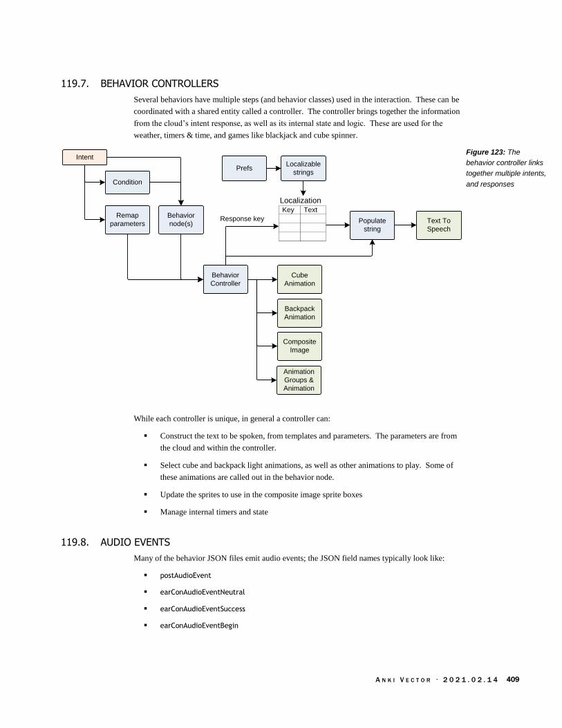
A N K I V E C T O R · 2 0 2 1 . 0 2 . 1 4 409
119.7. BEHAVIOR CONTROLLERS
Several behaviors have multiple steps (and behavior classes) used in the interaction. These can be
coordinated with a shared entity called a controller. The controller brings together the information
from the cloud’s intent response, as well as its internal state and logic. These are used for the
weather, timers & time, and games like blackjack and cube spinner.
Intent
Populate
string
Backpack
Animation
Behavior
node(s)
Condition
Text To
Speech
Cube
Animation
Prefs
Animation
Groups &
Animation
Composite
Image
Remap
parameters
Behavior
Controller
Localizable
strings
Response key
Key Text
Localization
While each controller is unique, in general a controller can:
Construct the text to be spoken, from templates and parameters. The parameters are from
the cloud and within the controller.
Select cube and backpack light animations, as well as other animations to play. Some of
these animations are called out in the behavior node.
Update the sprites to use in the composite image sprite boxes
Manage internal timers and state
119.8. AUDIO EVENTS
Many of the behavior JSON files emit audio events; the JSON field names typically look like:
postAudioEvent
earConAudioEventNeutral
earConAudioEventSuccess
earConAudioEventBegin
Figure 123: The
behavior controller links
together multiple intents,
and responses

A N K I V E C T O R · 2 0 2 1 . 0 2 . 1 4 410
CHAPTER 29
Emotion Model
This chapter describes Vector’s action, behaviour, and emotion system:
Actions and behaviour queues
The emotion-behaviour system, and stimulation
120. OVERVIEW
How does Vector get excited from praise? Vector has an emotional state that is seen in his affect –
his facial expression, head and arm posture – how he behaves and responds, as well as the actions
he initiates.
Audio Engine
Decay
Mood
Behavior Tree
Stimulation
Vectors mood is affected by external stimulation, and his feedback on his successes (and failures)
in his activities. His current mode affects the choices he makes and the behaviors he takes,
including those in response to events and stimulation. His emotional state is also reflected in how
the audio engine modulates its effects, even potentially choosing other effects or sounds. Vectors’
emotions are transitory though: heightened emotions decay, based on the stimulus and behavior
that drove them.
This emotion model and coupling their effects with other systems is managed by the
“MoodManager.”
121. EMOTIONS, AND STIMULATION
It’s thru stimulation of these emotions that Vector responds to praise. The label “emotion”
shouldn’t be taken too seriously, as it doesn’t model psychological moods, and other concepts. It
does just enough to convey character.
121.1. STIMULATION
Vector uses a concept of a stimulation level to guide how much he should initiate
“When stimulation is low, the robot is chill,”.. Vector is studiously observing but not
acting out. “Then if you start making noise, or make eye contact with the robot, and
certainly if you say ‘Hey Vector,’ that spikes [stimulation] way up...” But Vector also
picks up subtler actions–peripheral movement and noises, for instance, or the room lights
turning on and off. “If he gets stimulated enough, he’ll drive off his charger and start to
socialize with you, … say your name, greet you, give you a fist-bump, potentially.”
Figure 124: The
functional flow of the
mood
Captain 2018 quoting
Brad Neuman

A N K I V E C T O R · 2 0 2 1 . 0 2 . 1 4 411
Audio
Inputs
· Sound level
· Wake Word
· Intents
· Illumination
level
· Faces, Gaze
Stimulation
Video
Input
IMU
Pick Up / In-Air
Detector
Cliff
Sensors
· Fall Detector
· Fist Bump
· Poke
· Being held
PettingTouch
121.2. THE EMOTION MODEL
Stimulation is just one of the dimensions in Vector’s emotional model. Some dimensions are
influenced by the kind stimulation he is receiving, but others are from internal feedback Vectors
behaviors. Altogether he has five dimensions to his emotional state.
Stimulated (or the stimulation level) is from those sensory experiences described earlier;
Social, or “how eager [he] is to interact with users generally.” “Hearing his name
stimulates Vector, for instance, but it also makes him more social.”
Confident: “Vector’s confidence is affected by his success in the real world. The hooks on
his arms sometimes don’t line up with those on his cube, for instance, and he can’t pick it
up. Sometime he gets stuck while driving around. These failures make him feel less
confident, while successes make him more confident and more happy.”
Happy. This is Vectors sense that, overall, things are going well.
Trust56
Overall, Vector possesses just enough dimensions/aspects to his emotion model to drive responses
and his goal-driven behaviour, giving him a personality. When more dimensions are used, it is
harder to get them right, and the less convincing the character is when they aren’t.
121.3. SIMPLE MOODS
The emotions reflect short-term values across the 5 dimensions that arise as a result of stimuli.
Vector also has a simple mood that is distinguished from emotion by changing at a much slower
rate. A simple mood is a name that maps to some emotion value ranges. These are built into the
libcozmo_engine. The simple moods include:
Default
Frustrated
HighStim
LowStim
56 Trust was added in version 1.6. Vector initially only had the first four. Cozmo had nine, so it seems plausible that Vector would have developed more dimensions over time.
Figure 125: The
stimulation from
sensations
Wolford et al, 2018
Captain 2018

A N K I V E C T O R · 2 0 2 1 . 0 2 . 1 4 412
MedStim
It is not known how the mood interacts with the emotions.
121.4. INTERACTION WITH THE BEHAVIOR ENGINE
The behavior engine receives the stimulation events, and using a behavior tree, posts emotion
event to the mood manager. (The engine may base its decision what to post on the current
mood.) An emotion event is just an identifier string. The mood manager maps the emotion event
to an emotion affector. This is the emotion dimensions impacted by the event, values describing
how much the event impacts those emotion dimensions, and a decay graph that describes how the
heighten emotion fades away toward a neutral state.
Decay
MoodBehavior
Tree
Stimulation
Events
Behavior
Event NameEmotion
Affector
Emotion
Event
The active behaviors (which are also selected by the behavior tree) may post emotion events to the
mood manager as well.
121.5. MOOD MANAGER CONFIGURATION
At start up, the mood manager scans the configuration files building a table mapping the emotion
event names to the emotion affector.
The configuration files for the mood manager are located in a folder at:
/anki/data/assets/cozmo_resources/ config/engine/emotionevents
This is path hardcoded into libcozmo_engine. It is a folder that contains a set of JSON files, all
with the same structure. Each of these files is loaded. Each is a structure containing the following
fields:
Field Type Description
emotionEvents EmotionEvent[] An array emotion event structures (see below).
The EmotionEvent describes how the emotions respond to an event. It has the following
structure:
Field Type Description
name string The name of the event (see appendix K, Table 641:
The emotion event names)
emotionAffectors EmotionAffector[] The impact on the emotion state.
repetitionPenalty RepetitionPenalty This is a “time ratio” describing how the value
decays. Optional.
emotion event
Figure 126: Mapping
an emotion event to
how it impacts the
emotion model
Table 539:
CheckUpdateStatusRes
ponse JSON structure
Table 540:
EmotionEvent JSON
structure

A N K I V E C T O R · 2 0 2 1 . 0 2 . 1 4 413
The EmotionAffector describes how an emotion dimension should be modified:
Field Type Description
emotionType string The dimension or type of emotion (“Happy”,
“Confident”, “Stimulated”, “Social”, or “Trust”)
value float The value to add to the emotional state. The range
is usually -1 to 1
Altogether, the files respond to the following “emotion event” names. Some are external stimuli,
some are events in general, some are events regarding whether or not a behaviour succeeded, or
failed (failed with retry, failed with abort).
121.5.1 The RepetitionPenalty
The RepititionPenalty structure contains the following fields:
Field Type Description
nodes XY[] This is a “time ratio” describing how the value
decays with time.
121.5.2 The XY decay graph
The XY structure is used to define how a value (often the value associated with an emotion
dimension) should decay with time. This structure contains the following fields:
Field Type Description
x float With time graphs, this is “the time in seconds since
the most recent event (which changed the emotion
by more than some delta).”
With value slopes, this is “the emotion value.”
y float With time graphs, this is “the ratio of the original
value that should be reached by the given time.”
With value slopes, this is “the amount it decays
(towards zero) per minute as a fixed amount (not a
ratio).” The value never goes below zero.
121.6. MOOD CONFIGURATION
A mood configuration files is located at:
/anki/data/assets/cozmo_resources/ config/engine/mood_config.json
Table 541:
EmotionAffector JSON
structure
Table 542:
RepititionPenalty
structure
Table 543: XY structure

A N K I V E C T O R · 2 0 2 1 . 0 2 . 1 4 414
This is path hardcoded into libcozmo_engine.
The file is a structure containing the following fields:
Field Type Description
actionResultEmotionEvents TBD struct
audioParameterMap struct This is a structure that maps an emotion type to an
audio parameter’s string name. The audio
parameter is set to current emotion type’s value.
Optional
decayGraphs DecayGraph[] This describes how an emotion decays.
defaultRepetitionPenalty RepetitionPenalty This is a “time ratio” describing how the value
decays. Optional.
eventMapper struct
simpleMoodAudioParameters struct Optional
valueRanges ValueRange[] The allowed value ranges for given emotion types.
Note: this need not exhaustively define the range
for all emotion types. Values not listed should be
assumed to have a range of -1..1
The DecayGraph structure contains the following fields:
Field Type Description
emotionType string The dimension or type of emotion (“Happy”,
“Confident”, “Stimulated”, “Social”, or “Trust”).
“default” also matches
graphType string “TimeRatio” or “ValueSlope” . The default is
“TimeRatio”.
nodes XY[] Array of structures describing how the value decays
with time.
The ValueRange structure contains the following fields:
Field Type Description
emotionType string The dimension or type of emotion (“Happy”,
“Confident”, “Stimulated”, “Social”, or “Trust”)
max float The maximum value for the emotion type
min float The minimum value for the emotion type
122. REFERENCES & RESOURCES
Captain, Sean; Can emotional AI make Anki’s new robot into a lovable companion? , Fast
Company, 2018-8-8
https://www.fastcompany.com/90179055/can-emotional-ai-make-ankis-new-robot-into-a-
lovable-companion
Table 544: Mood config
JSON structure
Table 545: DecayGraph
structure
Table 546: ValueRange
structure

A N K I V E C T O R · 2 0 2 1 . 0 2 . 1 4 415
CHAPTER 30
Behavior Tree
This chapter describes Vector’s behaviour tree and how behaviors are configured:
Behavior trees, parameters for behaviors, conditions that allow a behavior or stop a
behavior
Cube spinner event mapping.
123. OVERVIEW
Behaviors are why Vector wants to shove stuff off of the desk.
Vector employs a behavior tree that decides if a behavior can run or can no longer run. It doesn’t
take it to the extreme a detailed decision tree scripting every action and response. Most of the
behavior tree is is focused on ensuring that transition between behaviors isn’t too abrupt, and
provides the settings (or preferences) for the behavior.
The fields and structures of the behavior tree are pretty ad hoc though. This seems to be the norm
in the video game industry
The “design principles” listed in this paper are a rather transparent attempt to impose a
structure on what might otherwise appear to be a random grab-bag of ideas – interesting,
perhaps, in and of themselves but not terribly cohesive as a whole.
124. BEHAVIOR TREE
The behavior tree is composed of nodes in JSON files. Each of the behavior nodes has a unique
identifier, called behaviorID. This is a way to make the records unique so that they can be looked
up. It is unlikely that it links to any special code or modules within libcozmo_engine.
The nodes also have a field – behaviorClass – that says how to interpret the node parameters, if the
behavior is activated. This class name links to code/modules within libcozmo_engine. There are
86 different behaviour classes.
Behavior nodes can initiate other behaviors. The identity of the behavior they launch may be
called out in the configuration of the node, or be hardcoded internally. To prevent loops, the chain
of the nodes must be acyclic. The concern is that a behavior node kicks off another (and so on),
eventually to a child node initiate another copy of the first node, leading to an infinite loop of
behaviors being started on pushed onto the stack. Not only doesn’t it give expected results,
eventually the software will run out of memory, and crash.
libcozmo_engine kicks off the initial behavior that forms the root of the tree. Vector, at the top
level, has 7 broad states:
PR demo
Factory test (e.g. the playpen tests)
Acoustic testing
On-boarding
Isla 2005
behavior tree nodes
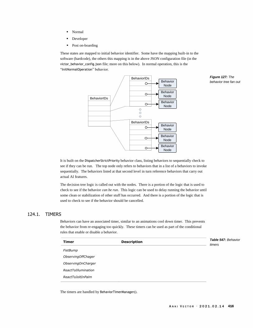
A N K I V E C T O R · 2 0 2 1 . 0 2 . 1 4 416
Normal
Developer
Post on-boarding
These states are mapped to initial behavior identifier. Some have the mapping built-in to the
software (hardcode), the others this mapping is in the above JSON configuration file (in the
victor_behavior_config.json file; more on this below). In normal operation, this is the
“InitNormalOperation” behavior.
BehaviorIDs
BehaviorIDsBehavior
Node
Behavior
Node
Behavior
Node
BehaviorIDsBehavior
Node
Behavior
Node
Behavior
Node
It is built on the DispatcherStrictPriority behavior class, listing behaviors to sequentially check to
see if they can be run. The top node only refers to behaviors that in a list of a behaviors to invoke
sequentially. The behaviors listed at that second level in turn reference behaviors that carry out
actual AI features.
The decision tree logic is called out with the nodes. There is a portion of the logic that is used to
check to see if the behavior can be run. This logic can be used to delay running the behavior until
some clean or stabilization of other stuff has occurred. And there is a portion of the logic that is
used to check to see if the behavior should be cancelled.
124.1. TIMERS
Behaviors can have an associated timer, similar to an animations cool down timer. This prevents
the behavior from re-engaging too quickly. These timers can be used as part of the conditional
rules that enable or disable a behavior.
Timer Description
FistBump
ObservingOffChager
ObservingOnCharger
ReactToIllumination
ReactToJoltInPalm
The timers are handled by BehaviorTimerManager().
Figure 127: The
behavior tree fan out
Table 547: Behavior
timers

A N K I V E C T O R · 2 0 2 1 . 0 2 . 1 4 417
124.2. CONFIGURATION
The configuration files for the behavior tree are located:
/anki/data/assets/cozmo_resources/ config/engine/behaviorComponent/victor_behavior_
config.json
This is path hardcoded into libcozmo_engine.
Note: most of the names of the structures in this chapter are arbitrary. They were made up to ease
readability and documentation. The files do not reference any such structure names.
124.3. BEHAVIOR NODE
The following fields are common to all behavior nodes:
Field Type Description
animationName string The name of an animation to play {note not a
trigger name}.
anonymousBehaviors Behavior[] A list of behaviors that are executed. Optional
associatedActiveFeature string Note: this is the high level AI feature, not the
feature gate. Optional
behaviors string[] Array of behavior names, in order; these
behaviorName are in the anonymousBehaviors array.
Can also be in…? Optional
behaviorClass string Often these are the same
behaviorID string
behaviorName
behaviors string If it is a string, this is the behaviorID of the
behavior to run.
string[]
If it is an array of strings, this is one or more
behaviors to run to in sequence. That is, the fist
behavior is initiated, and the current behavior node
is paused until the new completes. Then the next
one in the sequence is initiated, and so on in order.
BehaviorConfig[] If it is an array of structures, this is a set of possible
behaviors to run; they are picked randomly. based
on weight.
behaviorStatToIncrement string Optional
delegateID string
driveOffChargerBehavior
emotionEventOnActivated string e.g. RespondToShortVoiceCommand or
DanceToTheBeat. Optional.
faceSelectionPenalties
getInAnimation string The animation trigger name of the animation to
play when starting the behavior. Optional
getOutAnimation string The animation trigger name of the animation to
play when exiting the behavior. Optional
Table 548: Behavior
JSON structure
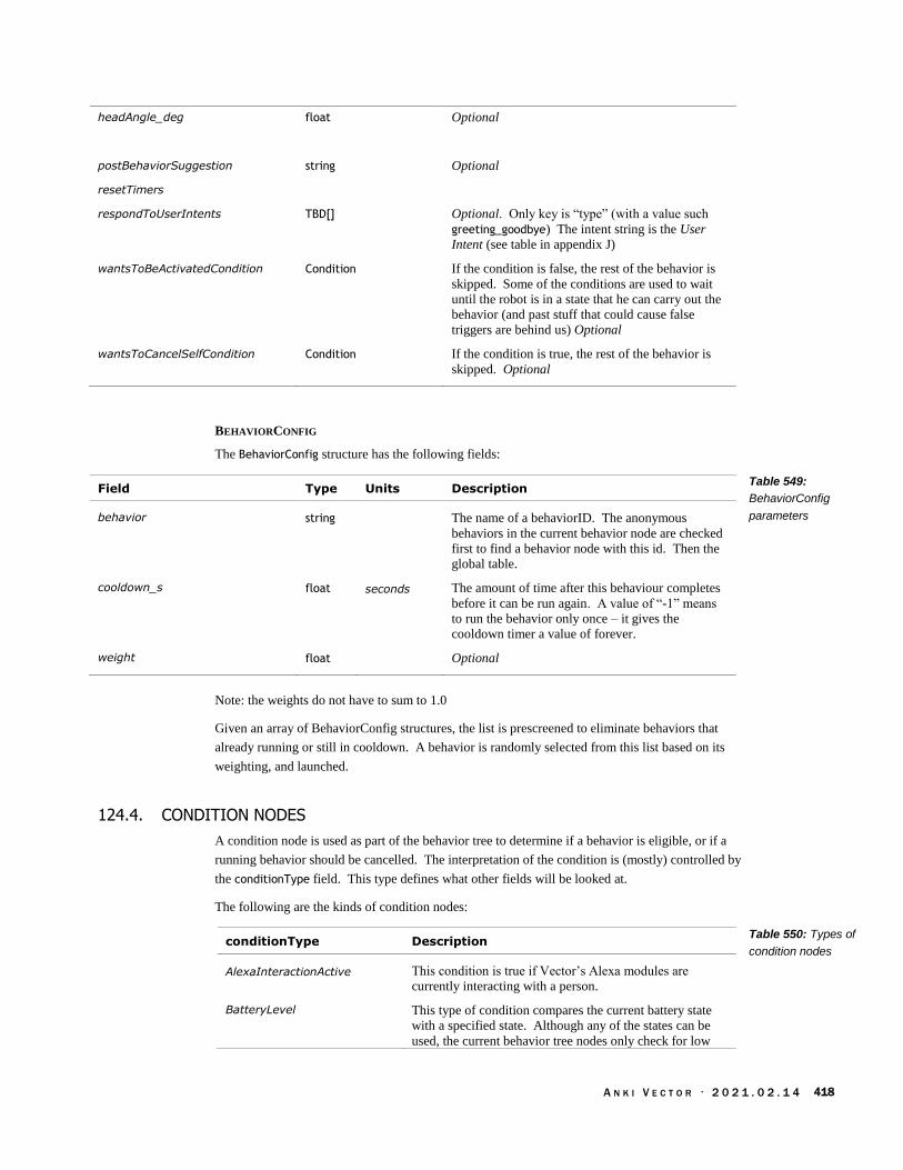
A N K I V E C T O R · 2 0 2 1 . 0 2 . 1 4 418
headAngle_deg float Optional
postBehaviorSuggestion string Optional
resetTimers
respondToUserIntents TBD[] Optional. Only key is “type” (with a value such
greeting_goodbye) The intent string is the User
Intent (see table in appendix J)
wantsToBeActivatedCondition Condition If the condition is false, the rest of the behavior is
skipped. Some of the conditions are used to wait
until the robot is in a state that he can carry out the
behavior (and past stuff that could cause false
triggers are behind us) Optional
wantsToCancelSelfCondition Condition If the condition is true, the rest of the behavior is
skipped. Optional
BEHAVIORCONFIG
The BehaviorConfig structure has the following fields:
Field Type Units Description
behavior string The name of a behaviorID. The anonymous
behaviors in the current behavior node are checked
first to find a behavior node with this id. Then the
global table.
cooldown_s float seconds The amount of time after this behaviour completes
before it can be run again. A value of “-1” means
to run the behavior only once – it gives the
cooldown timer a value of forever.
weight float Optional
Note: the weights do not have to sum to 1.0
Given an array of BehaviorConfig structures, the list is prescreened to eliminate behaviors that
already running or still in cooldown. A behavior is randomly selected from this list based on its
weighting, and launched.
124.4. CONDITION NODES
A condition node is used as part of the behavior tree to determine if a behavior is eligible, or if a
running behavior should be cancelled. The interpretation of the condition is (mostly) controlled by
the conditionType field. This type defines what other fields will be looked at.
The following are the kinds of condition nodes:
conditionType Description
AlexaInteractionActive This condition is true if Vector’s Alexa modules are
currently interacting with a person.
BatteryLevel This type of condition compares the current battery state
with a specified state. Although any of the states can be
used, the current behavior tree nodes only check for low
Table 549:
BehaviorConfig
parameters
Table 550: Types of
condition nodes

A N K I V E C T O R · 2 0 2 1 . 0 2 . 1 4 419
battery.
BeatDetected This condition is true if a music beat has been detected
BehaviorTimer This condition is true if
BeingHeld This condition is true if Vector is being held.
CarryingCube This condition is true if Vector is currently carrying a cube.
CliffDetected This type of condition is true if a cliff sensor has detected
an edge.
Compound This type of condition is used for boolean logic. It is the
only kind that recurses to other compound structures.
Emotion This condition is true if the value for the given emotion
dimension is above a threshold.
EyeContact This condition is true if someone is making eye contact
with Vector.
FeatureGate This type of condition is true if a specified AI feature is
active or inactive.
HighTemperature This type of condition is true if Vector’s temperature is
above an acceptable limit.
InCalmMode This type of condition is true if Vector is in a calm
emotional state.
IsMaintenanceReboot This type of condition is true if Vector has rebooted for a
software update or other maintenance reasons.
IsNightTime This type of condition is true if Vector [thinks it is night?
the illumination level is dark?]
MotionDetected This type of condition is true if Vector sees some motion
in his peripheral vision.
ObjectInitialDetection This condition is true if
ObjectKnown This condition is true if
ObstacleDetected This condition is true if Vector has encountered an
obstacle.
OffTreadsState This type of condition is true if Vector’s current state
matches a conditions such as on his tread, or has been
picked up, is being held, is being put back down, has fallen
(on his side). There is a time component to ensure that
state is stable, to prevent overreacting.
OnCharger This condition is true if Vector is currently on his charger
(i.e. he is in his dock) and it is providing energy.
OnChargerPlatform This condition is true if Vector is currently on his charger
(i.e. he is in his dock); it may or may not be providing any
energy.
ProxInRange
RobotHeldInPalm This condition checks whether or not Vector is being held.
RobotInHabitat This is true if Vector is in his habitat.
RobotPickedUp This type of condition is true if Vector is picked up – being
held. (does “in the air” count?)
RobotPitchInRange This type of condition is true if Vector’s pitch is within a
specified range.
RobotPlacedOnSlope

A N K I V E C T O R · 2 0 2 1 . 0 2 . 1 4 420
RobotRollInRange This type of condition is true if Vector’s roll is within a
specified range.
RobotShaken This type of condition is true if Vector has been shaken.
RobotTouched This type of condition is true if Vector has been
touched/petted (for at least a minimum duration).
SalientPointDetected This condition is true if
StuckOnEdge This type of condition is true if at least one tread has gone
over the edge. Perhaps the cliff sensors on one side show
in open space, perhaps Vector can tell that the tread isn’t
moving the robot?
TimedDedup This condition is true if
TimerInRange This condition is true if a specified timer is within a
specified value range.
TooHotToCharge
TriggerWordPending
TrueCondition This is condition is always true.
UnexpectedMovement
UserIsHoldingCube This is true if the user is holding the cube.
The Condition structure has the following possible fields:
Field Type Condition Type Description
and Condition[] Compound The condition is true iff all of the sub-
conditions are true; false otherwise. The
array must contain at least two conditions
The array must contain at least two
conditions. Optional
allowPotentialBeat boolean BeatDetected
begin_s float TimerInRange Wait for the timer to have been going for at
least this number of seconds.
conditionType string (all conditions) One of the conditions listed in Table 550:
Types of condition nodes
cooldown_s float BehaviorTimer The minimum duration between behaviors.
dedupInterval_ms int TimedDedup
emotion string Emotion The name of the emotion dimension to fetch
the value for.
expected boolean FeatureGate This is compared against the feature toggle
value, the FeatureGate condition is true iff
they have the same values.
feature string FeatureGate The name of the feature toggle, e.g.
“HowOldAreYou”
firstTimeOnly boolean ObjectInitialDetection
invalidSensorReturn boolean ProxInRange If true, matches when the proximal sensor is
unable to measure the distance to the object.
Default is false. Optional
maxAge_ms int ObjectKnown
Table 551: Condition
JSON structure

A N K I V E C T O R · 2 0 2 1 . 0 2 . 1 4 421
maxPitchThreshold_deg float RobotPitchInRange The maximum acceptable pitch reported by
the IMU.
maxProxDist_mm float ProxInRange The maximum acceptable distance reported
by the time of flight sensor.
maxRollThreshold_deg float RobotRollInRange The maximum acceptable roll angle reported
by the IMU.
maxTimeSinceChange_ms int OffTreadsState Optional
min Emotion The minimum acceptable value associated
with the given emotion dimension.
minAccelMagnitudeThresh
old uint RobotShaken The threshold (in milli-g’s?) for the
vibrations on the accelerometer to be
considered a shake event.
minDuration_ms uint CliffDetected The minimum amount of time that the cliff
sensors have registered an cliff of this
condition should be true. Optional
minDuration_s float RobotHeldInPalm The minimum amount of time that the rest of
this condition should be true. Optional
minPitchThreshold_deg float RobotPitchInRange The minimum acceptable pitch reported by
the IMU.
minProxDist_mm float ProxInRange The minimum acceptable distance reported
by the time of flight sensor.
minRollThreshold_deg float RobotRollInRange The minimum acceptable roll angle reported
by the IMU.
minTimeSinceChange_ms int OffTreadsState Optional
minTouchTime float RobotTouched The robot must be touched for at least this
duration (in seconds) this condition to be
true.
motionArea string MotionDetected The area of the vision that detected the
motion should match this string: “Left”,
“Right”, (potentially “Ground”)
motionLevel string MotionDetected “High”
not Condition Compound The condition is true iff the sub-condition is
false; otherwise the condition is false.
Optional
numCliffDetectionsToTrigg
er uint CliffDetected A count of the number separate cliff sensors
that are to trigger before a cliff is considered
to have been detected.
objectTypes string[] ObjectInitialDetection
ObjectKnown
The acceptable kinds of object kinds/faces to
meet this condition. Optional
or Condition[] Compound The condition is true if any of the sub-
conditions are true; false otherwise. The
array must contain at least two conditions.
Optional
shouldBeHeld boolean BeingHeld If true, the condition is true iff the robot is
currently being held. If false, the condition is
true iff the robot is not currently being held.
shouldBeHeldInPalm boolean RobotHeldInPalm If true, the condition is true iff the robot is
currently being held in the palm of a hand. If
false, the condition is true iff the robot is not
currently being held in the palm of a hand.

A N K I V E C T O R · 2 0 2 1 . 0 2 . 1 4 422
shouldDetectNoCliffs boolean CliffDetected If true, the condition is true iff a cliff has not
been detected.
subCondition Condition TimedDedup
targetBatteryLevel string BatteryLevel e.g. “Low”
targetSalientPoint string SalientPointDetected e.g. “Person” This could be other outputs of
the neural network matching.
targetState string OffTreadsState “Falling”, “InAir” , “OnBack”, “OnFace”,
“OnLeftSide”, “OnRightSide”, “OnTreads”
timerName string BehaviorTimer “ReactToIllumination”
125. A LOOK AT SOME INTERESTING BEHAVIORS
There are too many behavior classes to dig into. But a few are particularly fun to look at.
125.1. SHOVING STUFF OFF OF THE TABLE
The BumpObject class is likely the behavior that drives Vector to shove stuff off of desk. There is
only one behavior tree node with this class. It has the id ExploringBumpObject and is held in the file
/anki/data/assets/cozmo_resources/config/engine/behaviorComponent/behaviors/victorBehaviorTree/highLevelDelegates/exploring/exploringBumpObject.json
The BumpObject class takes the following extra parameters:
Field Type Units Description
maxDist_mm uint mm The maximum distance to the potential object to
bump.
minDist_mm uint mm The minimum distance to the potential object to bump
pBumpWhenEvil float Probability of bumping things when being evil?
pBumpWhenNotEvil float Probability of bumping things when not being evil?
pEvil float Probability of being evil?
125.2. POUNCING
Pouncing is where Vector springs forward to leap on an object, such as a finger.
Vector detects visual motion, and turns toward that (see motion detection). In this he
turns left (or right) to where he detected the motion (the Turn behavior class)
When he has a distance measurement (from the proximity sensor) (The PounceWithProx
behavior class)
When he is close enough, the animation takes over; he’ll make his facial expressions,
moves his arms, and tries to pin the object with his arms (“mousetrap”). Note: the
animations can’t be used to drive toward the target earlier; they aren’t linked into the
proximity sensors for driving.
If nothing else is happening, he’ll wait for up to 30 seconds before losing interest.
Table 552: BumpObject
behavior structure

A N K I V E C T O R · 2 0 2 1 . 0 2 . 1 4 423
A behavior tree node, using the DispatcherStrictPriority behavior class, coordinates these. The
DispatcherStrictPriority class takes the following extra parameters:
Field Type Units Description
interruptActiveBehavior boolean
The Turn class takes the following extra parameters:
Field Type Units Description
shouldTurnClockwise boolean True if Vector should turn clockwise; false if he
should turn counter clockwise
turnDegrees int The number of degrees to turn.
125.3. REACTING TO SOUND
Vector has two related behaviors for reacting to sound – deciding that there is some activity and
that he should react, or even play.
The ReactToSound behavior class is used to rouse Vector and respond if there are any sudden
noises, or there sounds like activity in the room:
Field Type Units Description
micAbsolutePowerThreshold float “a mic power above this will always be considered
a valid reaction sound” 0…4?
micConfidenceThresholdAtMinPower
float Used in conjunction with micMinPower? 0…5000
micDirectionReactionBehavior string The behavior ID to use for reactions
micMinPowerThreshold float “a mic power above this will require a confidence
of at least kRTS_ConfidenceThresholdAtMinPower to
be considered a valid reaction sound” 0..3 ? 999.9
is considered impossibly high”
The ReactToMicDirection behavior class is used to allow Vector to respond to direction that the
sound is coming from. It maps the sound direction to the terms “TwelveOClock”, “OneOClock”,
“ambient”, and has conditions like “OnSurface” and “OnCharger”.
See Chapter17, section 76.2 Spatial audio processing for where it the microphone sound is coming
from.
Table 553:
DispatcherStrictPriority
behavior structure
Table 554: Turn
behavior structure
Table 555:
ReactToSound
parameters

A N K I V E C T O R · 2 0 2 1 . 0 2 . 1 4 424
125.4. DANCING
Vector can dance to music, making moves in response to the beats. The dancing can be initiated
two different ways. The first step is if a beat is detected. The second is if Vector is verbally told
to dance.
Dance
dispatcher
Voice, App
Intent
Dance
Moves
Beat
Detector
Tempo
Listen for
the Beat
Dance to
the beat
coordinator
Beat detected Beat detected
The details of the beat detector and tempo measurement are in Chapter 18 section 76.5 Beat
Detection.
125.4.1 Dancing if a beat is detected
A behavior node (of behavior class “DanceToTheBeatCoordinator”) is regularly invoked as part of
the behavior tree (see section 124 Behavior Tree). This node has the pre-condition to check that a
beat has been detected. This isn’t quite the same as reacting sounds, but it is similar. The
BeatDetected condition structure has the following parameters:
Field Type Units Description
allowPotentialBeat boolean Default: false. Optional
If a beat has been heard, the DanceToTheBeatCoordinator proceeds in two phases. The first kicks
off a helper behavior to listen for music. If it detects music (beats), it then fires off a dance
behavior: there are two such behaviors, depending on whether or not it was on the charger. If there
is no music detected – or Vector is no longer on his treads – this behavior exits.
The behavior’s configuration structure has the following parameter fields:
Field Type Units Description
listeningBehavior string behaviorID The name of a behavior node to invoke.
longListeningBehavior string behaviorID The name of a behavior node to invoke.
offChargerDancingBehavior string behaviorID The name of a behavior node to invoke.
onChargerDancingBehavior string behaviorID The name of a behavior node to invoke.
125.4.2 Dancing by voice command
A behavior node (of behavior class “DanceToTheBeatVoiceCommand”) is regularly invoked as part
of the behavior tree (see section 124 Behavior Tree). Part of pre-conditions for being able to
execute this node is that someone has given Vector a command to dance. This is done by the
“respondToUsersIntents” condition including the “imperative_dance” intent. If there is no such
user intent pending, the node is skipped.
Figure 128: Flow of the
detecting and dancing to
music
Table 556:
BeatDetected
parameters
Table 557:
DanceToTheBeatCoordi
nator parameters

A N K I V E C T O R · 2 0 2 1 . 0 2 . 1 4 425
Otherwise, the intent is dequeued, Vector drives off of the charger, listen for the music beats, and
(if there are any) begins dancing.
125.4.3 Listening for the beat
The ListenForBeats behavior class is used to listen for multiple beats and to get the tempo. The
behavior exits once music has been heard, or if there is a timeout. Then the behavior node that
invoked it is then resumed to initiate the next step.
Perform
postListeningAnim
animation
Time out?
Yes
No
NoHeard Beat?
Perform
listeningAnim
animation
Yes
done
Perform
preListeningAnim
animation
Listen
Perform
noBeatAnim
animation
Set BeatDetected
to true
The behavior plays animations when it begins, ends, and if it doesn’t hear any beats. (If it does
hear beats, the dancing behaviors will play their own animations.) It sets the behavior tree variable
“BeatDetected” to true if it heard beats; otherwise it is set to false.
Figure 129:
ListenForBeats behavior
function

A N K I V E C T O R · 2 0 2 1 . 0 2 . 1 4 426
The behavior’s configuration structure has the following parameter fields:
Field Type Units Description
cancelSelfIfBeatLost boolean If true, exits the behavior when the beat has been
lost,
listeningAnim string The name of an animation trigger that is played
while listening for music and getting the tempo.
maxListeningTime_sec float seconds The maximum amount of time to listen for music
minListeningTime_sec float seconds Listen for at least this amount of time before
concluding that there is no music and exiting.
noBeatAnim string The name of an animation trigger that is played
when the behavior exits because there is no music
playing.
postListeningAnim string The name of an animation trigger that is played
after music has been detected, and is transitioning
to the dancing.
preListeningAnim string The name of an animation trigger that is played
when this behavior is started, before listening for
music has fully started.
The dance feature employs multiple instances of these to detect beats.
125.4.4 The Robo-boogie
Once Vector has decided to get his groove on, he chooses a dance from the many kinds of dances
of that he knows about. The dances themselves are partly-randomized sequences of dance move
animations that are coordinated the beats of the music.
The selection of the dance is performed using a node with the DispatcherRandom behavior class.
The different dances (as behaviors nodes) are listed in the “behaviors” array (along with some
weighting to help randomize with dance is selected). A new behavior – one that performs the
dancing – is randomly selected from this.
A particular dance is an instance of the DanceToTheBeat behavior class. A dance includes the
dance moves, whether the back pack lights can play along, and the facial expression.
Field Type Description
backpackAnim string The backpack animation trigger name to play while
dancing.
danceSessions DanceSession[] The dance moves that make up the dance.
eyeHoldAnim string The animation trigger name to animate the face
getOutAnim string The animation trigger name to play when exiting this
behavior.
useBackpackLights boolean If true, play the backpack lights animation. Default is
false(?)
Table 558:
ListenForBeats
parameters
Table 559:
DanceToTheBeat
parameters

A N K I V E C T O R · 2 0 2 1 . 0 2 . 1 4 427
The dance moves – called dance sessions – are made up of smaller animated movements called
“dance phrases.” They can (optionally) be coordinated with the beat of the music. These are
captured in the DanceSession structure:
Field Type Description
canListenForBeats boolean If true, then the animation (in the dance phrases) will be
synchronized with beats with the beat. If false, then the
beat events from the beat-detector will be ignored.
dancePhrases DancePhraseConfig[]
The sequence of (randomized) animations. These are
played in order.
playGetoutIfInterrupted boolean If true, and is interrupted by another animation, it plays
the animation specified by getOutAnim (in the
containing structure).
The dancing motions– dance phrases – are “made up of one or more possible dance animations …
strung together and played on sequential musical beats.” The DancePhraseConfig structure
“specifies the rules by which dance phrases are generated when the behavior is run.” These differ
from animation groups: here a random list of animations to play is created, rather than selecting
just one. This structure has the following fields:
Field Type Description
anims string[] The list of animation names (rather than trigger names)
to randomly draw from. There must be at least one
animation given.
maxBeats uint The animation is played no more than this number of
times.
minBeats uint The animation is played at least this number of times.
multipleOf uint The animation is played is a multiple of this number of
times.
“The number of animations that make up the phrase is random, but is always between ‘minBeats’
and ‘maxBeats’, and is always a multiple of ‘multipleOf’.” The “animations are randomly drawn
from the [anims] list in accordance with the min/max beats.”
If canListenForBeats (in the containing structure) is true, the animation (may) have an event key
frame that pauses the animation until a musical beat is heard and a DANCE_BEAT_SYNC event is sent
to the animation engine. In this case, the animations must have one event key frame, and the
event_id must be “DANCE_BEAT_SYNC”.
126. USER CONDITIONS
There is an unusual configuration file that looks like it was intended to allow some user defined
behaviors, tuning of behaviours or responses:
/anki/data/assets/cozmo_resources/ config/engine/userDefinedBehaviorTree/conditionTo
BehaviorMaps.json
This is path hardcoded into libcozmo_engine. It is a configuration that links to a bunch of
backpack and cube lights patterns.
Table 560:
DanceSession
parameters
Table 561:
DancePhraseConfig
parameters

A N K I V E C T O R · 2 0 2 1 . 0 2 . 1 4 428
127. REFERENCES & RESOURCES
Isla, Damian; Handling Complexity in the Halo 2 AI, GDC 2005 Proceeding, 2005 March 11
https://www.gamasutra.com/view/feature/130663/gdc_2005_proceeding_handling_.php
It is said that this presentation kicked off the widespread use of behavior trees in video games.

A N K I V E C T O R · 2 0 2 1 . 0 2 . 1 4 429
PART VII
Maintenance
This part describes practical items to support Vector’s operation.
SETTINGS, PREFERENCES, FEATURES AND STATISTICS. A look at how Vector syncs with remote
servers
SOFTWARE UPDATES. How Vector’s software updates are applied.
DIAGNOSTICS & STATS. The diagnostic support built into Vector, including logging and usage
statistics
drawing by Steph Dere

A N K I V E C T O R · 2 0 2 1 . 0 2 . 1 4 430
[This page is intentionally left blank for purposes of double-sided printing]

A N K I V E C T O R · 2 0 2 1 . 0 2 . 1 4 431
CHAPTER 31
Settings, Preferences,
Features, and Statistics
This chapter describes:
The owner’s account settings and entitlements
The robot’s settings (owner preferences)
The robot’s lifetime stats
128. THE ARCHITECTURE
The architecture for setting and storing settings, statistics, account information is:
Mobile App
JDocs
server
Mobile App
& Python
SDK
applications
/net/connman/service/wifi_..._managed_psk
/dev/socket/_jdocs_engine_client
/dev/socket/_switchboard_gateway_server
Vic-Gateway
Vic-Switchbox
/dev/socket/jdocs_server
Vic-Engine
WiFi
Configuration
Vic-Cloud
The Vic-Cloud service accesses information on a remote server.
The Vic-Switchbox interacts with the WiFi subsystem (connman) to allow the mobile App to set
the preferred WiFi network to use. The mobile app must use Bluetooth LE to do this.
Vic-Gateway interacts with the mobile App and SDK programs to changes the robot settings.
Vic-Engine receives the preferences from the Vic-Cloud and Vic-Gateway, to carry out an changes
in behaviour of Vector.
128.1. STORAGE LOCATION
Many of the settings are stored in the “/data/” folder which is located on the modifiable
“userdata” partition.
The settings in the “/data/data/com.anki.victor/persistent/jdocs” folder are all JSON files with
the following fields:
Figure 130: The
architecture for storing
preferences, account
info, entitlements, and
tracking stats

A N K I V E C T O R · 2 0 2 1 . 0 2 . 1 4 432
Field Type Description
client_meta string The string is always empty.
cloud_accessed bool This is always true
cloud_dirty_remaining_sec
uint This is always true
cloud_get_time uint The time stamp of the cloud settings?
doc_version uint64 A number used to uniquely identify changes to the setting structure, and be
able to tell which one is the more recent settings. Most often this is the
number of times that the settings have been changed.
fmt_version uint64 The version number of the jdoc structure schema; this is always 1.
jdoc struct The settings structure for this kind of jdoc. (These will be discussed below.)
129. WIFI CONFIGURATION
The WiFi configuration (aka settings or preferences) is entirely local to the Vector robot. The
information about the WiFi settings is not stored remotely.
The mobile application can configuration the WiFi settings via Vic-Switchbox commands. The
WiFi is managed by connman thru the Vic-Switchbox:
To provide a list of WiFi SSIDs to the mobile app
To allow the mobile app to select an SSID and provide a password to
Tell it forget an SSID
To place the WiFi into Access Point mode
The WIFI configuration is stored in folders located in “/data/lib/connman/” and is managed by
connmanctl. The folder names are based on the SSID (stored as a decimal number) and the WiFi
security method. Within each folder is s settings file that contains the SSID, the passphrase, and
other settings for that WiFi access point.
130. THE OWNER ACCOUNT INFORMATION
The owner account information is sent from the mobile application to Anki servers at time of
registration and setting up a Vector. The owner account information includes:57
JSON Key units Description & Notes
user_id base64 A base64 token to identify the user
created_by_app_name string The name of the mobile application that register the owner.
Example: “chewie”
created_by_app_platform string The mobile OS version string when the mobile application created
the owners account. Example “ios 12.1.2; iPhone8,1
created_by_app_version string The version of the mobile application that register the owner.
Example: “1.3.1”
deactivation_reason
dob YYYY-MM-DD The owner’s date of birth (the one given at time of registration)
57 It is not clear why there is so much information, and why this is sent from the Jdocs server in so many cases.
Table 562: Persistent
structure JDoc files
Table 563: The
owners account
information
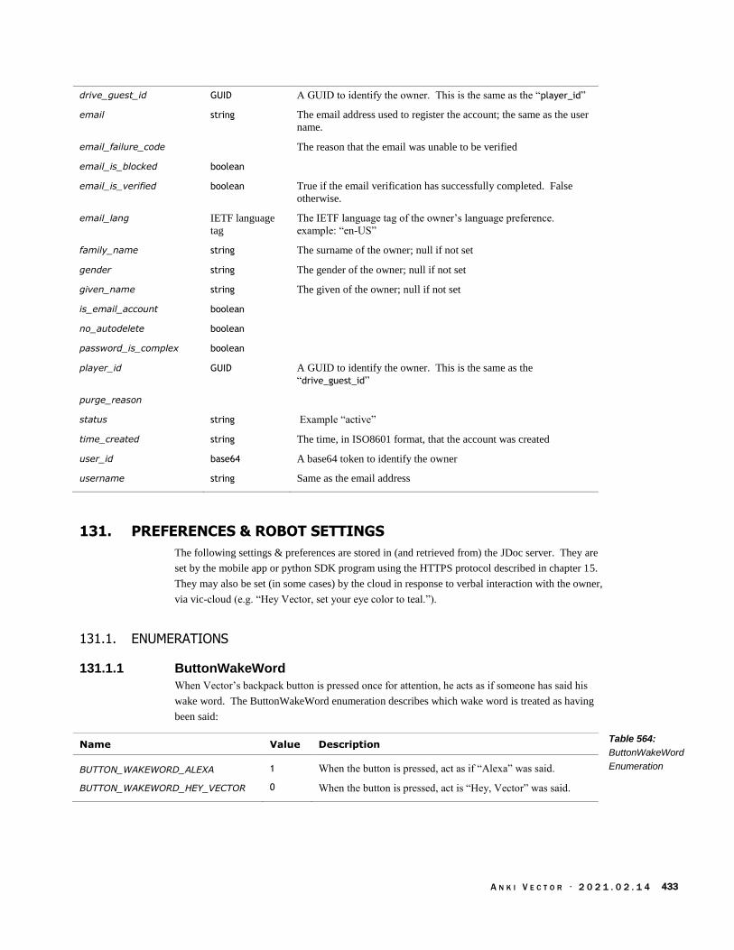
A N K I V E C T O R · 2 0 2 1 . 0 2 . 1 4 433
drive_guest_id GUID A GUID to identify the owner. This is the same as the “player_id”
email string The email address used to register the account; the same as the user
name.
email_failure_code The reason that the email was unable to be verified
email_is_blocked boolean
email_is_verified boolean True if the email verification has successfully completed. False
otherwise.
email_lang IETF language
tag
The IETF language tag of the owner’s language preference.
example: “en-US”
family_name string The surname of the owner; null if not set
gender string The gender of the owner; null if not set
given_name string The given of the owner; null if not set
is_email_account boolean
no_autodelete boolean
password_is_complex boolean
player_id GUID A GUID to identify the owner. This is the same as the
“drive_guest_id”
purge_reason
status string Example “active”
time_created string The time, in ISO8601 format, that the account was created
user_id base64 A base64 token to identify the owner
username string Same as the email address
131. PREFERENCES & ROBOT SETTINGS
The following settings & preferences are stored in (and retrieved from) the JDoc server. They are
set by the mobile app or python SDK program using the HTTPS protocol described in chapter 15.
They may also be set (in some cases) by the cloud in response to verbal interaction with the owner,
via vic-cloud (e.g. “Hey Vector, set your eye color to teal.”).
131.1. ENUMERATIONS
131.1.1 ButtonWakeWord
When Vector’s backpack button is pressed once for attention, he acts as if someone has said his
wake word. The ButtonWakeWord enumeration describes which wake word is treated as having
been said:
Name Value Description
BUTTON_WAKEWORD_ALEXA 1 When the button is pressed, act as if “Alexa” was said.
BUTTON_WAKEWORD_HEY_VECTOR 0 When the button is pressed, act is “Hey, Vector” was said.
Table 564:
ButtonWakeWord
Enumeration
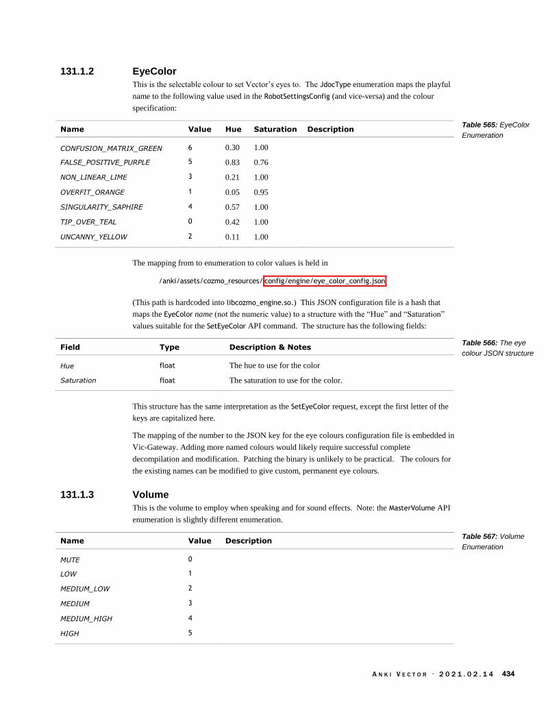
A N K I V E C T O R · 2 0 2 1 . 0 2 . 1 4 434
131.1.2 EyeColor
This is the selectable colour to set Vector’s eyes to. The JdocType enumeration maps the playful
name to the following value used in the RobotSettingsConfig (and vice-versa) and the colour
specification:
Name Value Hue Saturation Description
CONFUSION_MATRIX_GREEN 6 0.30 1.00
FALSE_POSITIVE_PURPLE 5 0.83 0.76
NON_LINEAR_LIME 3 0.21 1.00
OVERFIT_ORANGE 1 0.05 0.95
SINGULARITY_SAPHIRE 4 0.57 1.00
TIP_OVER_TEAL 0 0.42 1.00
UNCANNY_YELLOW 2 0.11 1.00
The mapping from to enumeration to color values is held in
/anki/assets/cozmo_resources/ config/engine/eye_color_config.json
(This path is hardcoded into libcozmo_engine.so.) This JSON configuration file is a hash that
maps the EyeColor name (not the numeric value) to a structure with the “Hue” and “Saturation”
values suitable for the SetEyeColor API command. The structure has the following fields:
Field Type Description & Notes
Hue float The hue to use for the color
Saturation float The saturation to use for the color.
This structure has the same interpretation as the SetEyeColor request, except the first letter of the
keys are capitalized here.
The mapping of the number to the JSON key for the eye colours configuration file is embedded in
Vic-Gateway. Adding more named colours would likely require successful complete
decompilation and modification. Patching the binary is unlikely to be practical. The colours for
the existing names can be modified to give custom, permanent eye colours.
131.1.3 Volume
This is the volume to employ when speaking and for sound effects. Note: the MasterVolume API
enumeration is slightly different enumeration.
Name Value Description
MUTE 0
LOW 1
MEDIUM_LOW 2
MEDIUM 3
MEDIUM_HIGH 4
HIGH 5
Table 565: EyeColor
Enumeration
Table 566: The eye
colour JSON structure
Table 567: Volume
Enumeration

A N K I V E C T O R · 2 0 2 1 . 0 2 . 1 4 435
131.2. ROBOTSETTINGSCONFIG
The entitlement settings associated with the user account (as opposed to the per-robot settings) are
stored in the cloud. The settings are retrieved and a local copy is located at in:
/data/data/com.anki.victor/persistent/jdocs/ vic.RobotSettings .json
The file is specified in the “jdocs_config.json” file (see Chapter 17, section 72 JDocs Server) by
the “docName” key within the “ROBOT_SETTINGS” subsection. The “jdoc” field is a
RobotSettingsConfig structure with the following fields:
Field Type Description & Notes
button_wakeword ButtonWakeWord When the button is pressed, act as if this wake word (“Hey
Vector” vs “Alexa”) was spoken.
default: 0 (“Hey Vector”)
clock_24_hour boolean If false, use a clock with AM and PM and hours that run from 1 to
12. If true, use a clock with hours that run from 1 to 24.
default: false
default_location string default: “San Francisco, California, United States”
dist_is_metric boolean If true, use metric units for distance measures; if false, use
imperial units.
default: false
eye_color EyeColor The colour used for the eyes. The colour is referred to by one of
an enumerated set. (Within the SDK, the eyes can be set to a
colour by hue and saturation, but this is not permanent.)
default: 0 (TIP_OVER_TEAL)
locale strong The IETF language tag of the owner’s language preference –
American English, UK English, Australian English, German,
French, Japanese, etc.
default: “en-US”
master_volume Volume default: 4 (MEDIUM_HIGH)
temp_is_fahrenheit boolean If true, use Fahrenheit for temperature units; otherwise use
Celsius.58
default: true
time_zone string The “tz database name” for time zone to use for the time and
alarms.
default: “America/Los_Angeles”
The default values for each of the settings are held in:
/anki/assets/cozmo_resources/ config/engine/settings_config.json
(This path is hardcoded into libcozmo_engine.so.) The file is a JSON structure that maps each of
the fields of RobotSettingsConfig to a control structure. Each control structure has the following
fields:
58 Anyone else notice that metric requires a true for distance, but a false for temperature? Parity.
Table 568: The
RobotSettingsConfig
JSON structure

A N K I V E C T O R · 2 0 2 1 . 0 2 . 1 4 436
Field Type Description & Notes
defaultValue The value to employ unless one has been given by the operator or
other precedent.
updateCloudOnChange boolean true if the value is pushed to the colour when it is changed by the
operator. False if not. Won’t be restored..?
It is implied that the setting value is to be pulled from the Cloud when the robot is restored after
clearing.
132. OWNER ENTITLEMENTS
An entitlement is a family of features or resources that the program or owner is allowed to use. It
is represented as set of key-value pairs. This is a concept that Anki provided provision for but was
not used in practice.
The only entitlement defined in Vector’s API (and internal configuration files) is “kickstarter eyes”
(JSON key “KICKSTARTER_EYES”). Anki decided not to pursue this, and its feature(s) remain
unimplemented.
The entitlement settings associated with the account (as opposed to the per-robot settings) are
stored in the cloud. The settings are retrieved and a local copy is located at in:
/data/data/com.anki.victor/persistent/jdocs/ vic.UserEntitlements .json
The file is specified in the “jdocs_config.json” file (see Chapter 17, section 72 JDocs Server) by
the “docName” key within the “ACCOUNT_SETTINGS” subsection. The default entitlement settings
are held in
/anki/assets/cozmo_resources/ config/engine/userEntitlements_config.json
(This path is hardcoded into libcozmo_engine.so.) The file is a JSON structure that maps each of
the entitlement to a control structure. The control structure is the same as Table 569: The setting
control structure, used in settings in the previous section.
133. VESTIGAL COZMO SETTINGS
The settings associated with the account (as opposed to the per-robot settings) are stored in the
cloud. The settings are retrieved and a local copy is located at in:
/data/data/com.anki.victor/persistent/jdocs/ vic.AccountSettings .json
The file is specified in the “jdocs_config.json” file (see Chapter 17, section 72 JDocs Server) by
the “docName” key within the “ACCOUNT_SETTINGS” subsection. The “jdoc” field is a structure
with the following settings:
Field Type Description & Notes
APP_LOCALE string The IETF language tag of the owner’s language preference –
American English, UK English, Australian English, German,
French, Japanese, etc.
default: “en-US”
DATA_COLLECTION boolean default: false
Table 569: The setting
control structure
Table 570: The
Cozmo account
settings

A N K I V E C T O R · 2 0 2 1 . 0 2 . 1 4 437
The default “account settings” are held in:
/anki/etc/ config/engine/accountSettings_config.json
This path is hardcoded into libcozmo_engine.so and these settings are only read (possibly) by vic-
gateway. The file is a JSON structure that maps each of the settings to a control structure. The
control structure is the same as Table 569: The setting control structure, used in settings in an
earlier section.
134. FEATURE FLAGS
Vector has granular features that can be enabled and disabled thru the use of feature flags. Feature
flags allow the code to be deployed, and selectively enabled. As a software engineering practice, a
feature is usually is disabled because the feature is:
not yet fully developed, or
specific to a customer, or
mostly developed and being tested in some groups, or
only enabled when there is some error occurs or other functionality is not working
intended, or
a special/premium function sold at a cost or reward (like an entitlement).
Many of these possibilities do not apply to Anki. But some do. Many of the disabled features are
probably disabled because they are incomplete, do not work, and likely not to work for without
further development.
134.1. CONFIGURATION FILE
The features flag configuration file is located at:
/anki/data/assets/cozmo_resources/ config/features.json
(This path is hardcoded into libcozmo_engine.so.) This file is organized as an array of structures
with the following fields:
Field Type Description & Notes
enabled boolean True if the feature is enabled, false if not
feature string The name of the feature
The set of feature flags and their enabled/disabled state can be found in Appendix I. The features
are often used as linking mechanisms of the modules. It is likely modules of behavior /
functionality.
134.2. COMMUNICATION INTERFACE TO THE FEATURES
The list of features can be queried with the GetFeatureFlagList command. The status of each
individual feature (whether it is enabled or not) can be found with the GetFeatureFlag query. See
Chapter 15 section 57 Features & Entitlements for more details.
Table 571: The
feature flag structure

A N K I V E C T O R · 2 0 2 1 . 0 2 . 1 4 438
135. ROBOT LIFETIME STATISTICS & EVENTS
Vector summarizes his experiences and activities into a set of fun measures. The intent is that they
can be shared as attaboys and a novel dashboard. They may also have been used in product
planning to prioritize new behaviors and firmware features, and next generation product needs.
The lifetime statics are updated by the robot and sent to the server; a local copy is located at in a
JSON file:
/data/data/com.anki.victor/persistent/jdocs/ vic.RobotLifetimeStats .json
The file is specified in the “jdocs_config.json” file (see Chapter 17, section 72 JDocs Server) by
the “docName” key within the “ROBOT_LIFETIME_STATS” subsection. The “jdoc” field holds a
structure with the following fields:
Key units Description & Notes
Alive.seconds seconds Vector’s age, since he was given preferences (a factory reset
restarts this)
Stim.CumlPosDelta The lifetime (cumulative) sensory score.
BStat.AnimationPlayed count The number of animations played
BStat.BehaviorActivated count
BStat.AttemptedFistBump count The number of fist bumps (attempted)
BStat.FistBumpSuccess count
BStat.PettingBlissIncrease
BStat.PettingReachedMaxBliss
BStat.ReactedToCliff count
BStat.ReactedToEyeContact count
BStat.ReactedToMotion count
BStat.ReactedToSound count
BStat.ReactedToTriggerWord count
Feature.AI.DanceToTheBeat
Feature.AI.Exploring
Feature.AI.FistBump
Feature.AI.GoHome
Feature.AI.InTheAir
Feature.AI.InteractWithFaces count The number of times recognized / interacted with faces
Feature.AI.Keepaway
Feature.AI.ListeningForBeats
Feature.AI.LowBattery
Feature.AI.Observing
Feature.AI.ObservingOnCharger
Feature.AI.Onboarding
Feature.AI.Sleeping
Feature.AI.Petting ms The amount of time petted
Table 572: The robot
lifetime stats schema

A N K I V E C T O R · 2 0 2 1 . 0 2 . 1 4 439
Feature.AI.ReactToCliff
Feature.AI.StuckOnEdge
Feature.AI.UnmatchedVoiceIntent
Feature.Voice.VC_Greeting
FeatureType.Autonomous
FeatureType.Failure
FeatureType.Sleep
FeatureType.Social
FeatureType.Play
FeatureType.Utility count The number of utilities used
Odom.LWheel mm The left wheel odometer – how far it has driven
Odom.Rwheel mm The right wheel odometer – how far it has driven
Odom.Body
Pet.ms ms The cumulative time petted
The statistics are retrievable by the application.
136. REFERENCES & RESOURCES
Wikipedia, List of tz database time zones,
https://en.wikipedia.org/wiki/List_of_tz_database_time_zones
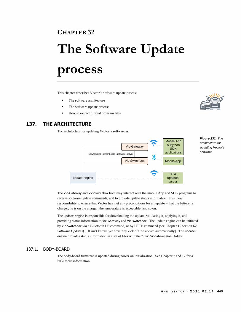
A N K I V E C T O R · 2 0 2 1 . 0 2 . 1 4 440
CHAPTER 32
The Software Update
process
This chapter describes Vector’s software update process
The software architecture
The software update process
How to extract official program files
137. THE ARCHITECTURE
The architecture for updating Vector’s software is:
Mobile App
OTA
updates
server
Mobile App
& Python
SDK
applications/dev/socket/_switchboard_gateway_server
Vic-Gateway
Vic-Switchbox
update-engine
The Vic-Gateway and Vic-Switchbox both may interact with the mobile App and SDK programs to
receive software update commands, and to provide update status information. It is their
responsibility to ensure that Vector has met any preconditions for an update – that the battery is
charger, he is on the charger, the temperature is acceptable, and so on.
The update-engine is responsible for downloading the update, validating it, applying it, and
providing status information to Vic-Gateway and Vic-switchbox. The update engine can be initiated
by Vic-Switchbox via a Bluetooth LE command, or by HTTP command (see Chapter 15 section 67
Software Updates). [It isn’t known yet how they kick off the update automatically]. The update-
engine provides status information in a set of files with the “/run/update-engine” folder.
137.1. BODY-BOARD
The body-board firmware is updated during power on initialization. See Chapter 7 and 12 for a
little more information.
Figure 131: The
architecture for
updating Vector’s
software

A N K I V E C T O R · 2 0 2 1 . 0 2 . 1 4 441
137.2. THE COMPANION CUBE FIRMWARE
The cube firmware is updated (or downloaded if not present at all) when the Bluetooth LE
subsystem finds a cube. See Chapter 14 for details.
138. THE UPDATE FILE
The update files are TAR files with a suffix “OTA” (over the air update). The TAR file has a fixed
structure, with some of the files encrypted. There are 3 kinds of update files
Factory updates. These modify the ABOOT, RECOVERY and RECOVERYFS partitions – the
aboot boot-loader, the recovery Linux kernel (and initramfs), and its file system.
Production updates. These modify the BOOT, and SYSTEM partitions – the main Linux
kernel (and initramfs), and the file system.
Delta updates. These modify the main file system partitions; by sending only the changes
to the underlying partitions, the updates can be very compact.
The archive contains 3 to 5 files, and they must be in the following order:
file name Description
manifest.ini This provides a description of which Vector units this update can be
applied to, a list of the update files, including their compression &
encryption schemes, and their signature.
manifest.sha256 This is a sha256 digest produced when the manifest is signed with
secret OTA key. This is used to ensure that the manifest is valid.
apq8009-robot-delta.bin.gz This holds the changes to the disk at a block level. This is present
only in delta updates. It is optionally encrypted.
apq8009-robot-emmc_appsboot.img.gz
This provides a new ABOOT partition. This is present only in factory
updates. To unlock Vectors, making them developer units, the
modified (and signed) aboot is provided using this type of updater. It
is optionally encrypted.
apq8009-robot-boot.img.gz In factory updates it will be applied to the RECOVERY partition;
otherwise it will be applied to the BOOT partition. This is not present
in delta updates. It is optionally encrypted.
apq8009-robot-sysfs.img.gz In factory updates it will be applied to the RECOVERYFS partition;
otherwise it will be applied to the SYSTEM partition. This is not present
in delta updates. It is optionally encrypted.
138.1. MANIFEST.INI
The manifest.ini is checked by verifying its signature59 against manifest.sha256 using a secret key
(/anki/etc/ota.pub):
openssl dgst \ -sha256 \ -verify /anki/etc/ota.pub \ -signature /run/update-engine/manifest.sha256 \ /run/update-engine/manifest.ini
59 I’m using the information originally at: https://github.com/GooeyChickenman/victor/tree/master/firmware
Table 573: The
contents of an over-
the-air update archive
file
Example 8: Checking
the manifest.ini
signature
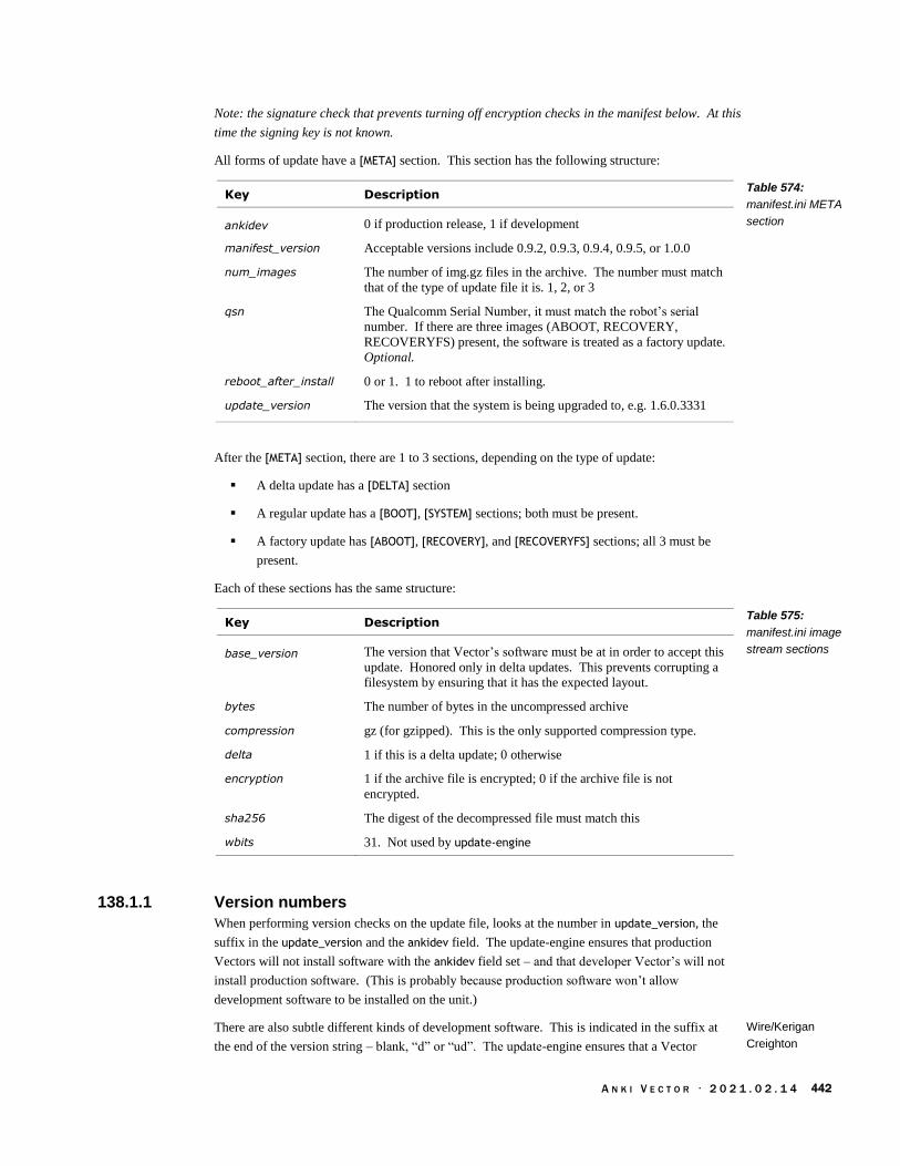
A N K I V E C T O R · 2 0 2 1 . 0 2 . 1 4 442
Note: the signature check that prevents turning off encryption checks in the manifest below. At this
time the signing key is not known.
All forms of update have a [META] section. This section has the following structure:
Key Description
ankidev 0 if production release, 1 if development
manifest_version Acceptable versions include 0.9.2, 0.9.3, 0.9.4, 0.9.5, or 1.0.0
num_images The number of img.gz files in the archive. The number must match
that of the type of update file it is. 1, 2, or 3
qsn The Qualcomm Serial Number, it must match the robot’s serial
number. If there are three images (ABOOT, RECOVERY,
RECOVERYFS) present, the software is treated as a factory update.
Optional.
reboot_after_install 0 or 1. 1 to reboot after installing.
update_version The version that the system is being upgraded to, e.g. 1.6.0.3331
After the [META] section, there are 1 to 3 sections, depending on the type of update:
A delta update has a [DELTA] section
A regular update has a [BOOT], [SYSTEM] sections; both must be present.
A factory update has [ABOOT], [RECOVERY], and [RECOVERYFS] sections; all 3 must be
present.
Each of these sections has the same structure:
Key Description
base_version The version that Vector’s software must be at in order to accept this
update. Honored only in delta updates. This prevents corrupting a
filesystem by ensuring that it has the expected layout.
bytes The number of bytes in the uncompressed archive
compression gz (for gzipped). This is the only supported compression type.
delta 1 if this is a delta update; 0 otherwise
encryption 1 if the archive file is encrypted; 0 if the archive file is not
encrypted.
sha256 The digest of the decompressed file must match this
wbits 31. Not used by update-engine
138.1.1 Version numbers
When performing version checks on the update file, looks at the number in update_version, the
suffix in the update_version and the ankidev field. The update-engine ensures that production
Vectors will not install software with the ankidev field set – and that developer Vector’s will not
install production software. (This is probably because production software won’t allow
development software to be installed on the unit.)
There are also subtle different kinds of development software. This is indicated in the suffix at
the end of the version string – blank, “d” or “ud”. The update-engine ensures that a Vector
Table 574:
manifest.ini META
section
Table 575:
manifest.ini image
stream sections
Wire/Kerigan
Creighton
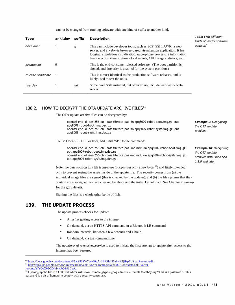
A N K I V E C T O R · 2 0 2 1 . 0 2 . 1 4 443
cannot be changed from running software with one kind of suffix to another kind.
Type anki.dev suffix Description
developer 1 d This can include developer tools, such as SCP, SSH, AWK, a web
server, and a web-viz browser-based visualization application. It has
logging, simulation visualization, microphone processing information,
beat detection visualization, cloud intents, CPU usage statistics, etc.
production 0 This is the end-consumer released software. (The boot partition is
signed, and dmverity is enabled for the system partition.)
release candidate 1 This is almost identical to the production software releases, and is
likely used to test the units.
userdev 1 ud Some have SSH installed, but often do not include web-viz & web-
server.
138.2. HOW TO DECRYPT THE OTA UPDATE ARCHIVE FILES61
The OTA update archive files can be decrypted by:
openssl enc -d -aes-256-ctr -pass file:ota.pas -in apq8009-robot-boot.img.gz -out apq8009-robot-boot.img.dec.gz openssl enc -d -aes-256-ctr -pass file:ota.pas -in apq8009-robot-sysfs.img.gz -out apq8009-robot-sysfs.img.dec.gz
To use OpenSSL 1.1.0 or later, add “-md md5” to the command:
openssl enc -d -aes-256-ctr -pass file:ota.pas -md md5 -in apq8009-robot-boot.img.gz -out apq8009-robot-boot.img.dec.gz openssl enc -d -aes-256-ctr -pass file:ota.pas -md md5 -in apq8009-robot-sysfs.img.gz -out apq8009-robot-sysfs.img.dec.gz
Note: the password on this file is insecure (ota.pas has only a few bytes62) and likely intended
only to prevent seeing the assets inside of the update file. The security comes from (a) the
individual image files are signed (this is checked by the updater), and (b) the file systems that they
contain are also signed, and are checked by aboot and the initial kernel load. See Chapter 7 Startup
for the gory details.
Signing the files is a whole other kettle of fish.
139. THE UPDATE PROCESS
The update process checks for update:
After 1st getting access to the internet
On demand, via an HTTPS API command or a Bluetooth LE command
Random intervals, between a few seconds and 1 hour.
On demand, via the command line.
The update-engine-oneshot.service is used to initiate the first attempt to update after access to the
internet has been restored.
60 https://docs.google.com/document/d/1KZ93SW7geM0gA-LBXHdt55a9NR1jfKp7UZyqlRuokno/edit 61 https://groups.google.com/forum/#!searchin/anki-vector-rooting/ota.pas%7Csort:date/anki-vector-
rooting/YlYQsX08OD4/fvkAOZ91CgAJ 62 Opening up the file in a UTF text editor will show Chinese glyphs; google translate reveals that they say “This is a password”. This password is a bit of humour to comply with a security consultant.
Table 576: Different
kinds of Vector software
updates60
Example 9: Decrypting
the OTA update
archives
Example 10: Decrypting
the OTA update
archives with Open SSL
1.1.0 and later

A N K I V E C T O R · 2 0 2 1 . 0 2 . 1 4 444
The /sbin/update-os can be used to initiate the software update process from the command-line on
developer units. This acts as if the vic-switchboard had initiated the download and install.
Downgrading is automatically enabled. This command is new to version 1.7.
139.1. STATUS DIRECTORY
The update-engine provides its status thru a set of files in the /run/update-engine folder.
File Description
done If this file exists, the OTA update process has completed, and the
system is preparing “to reboot into the new OS version.” This is
used to prevent “another OTA download and install in this case.”
error This file is set if there has been an error in the update process. The
error code representing why the update failed. See Appendix D,
Table 606: OTA update-engine status codes. It can also have a
value of “Unclean exit” by default.
expected-download-size
The expected file size (the given total size of the OTA file) to
download.
expected-size In non-delta updates, the total number of bytes of the unencrypted
image files. This is the sum of the “bytes” field in the sections.
phase A short label indicating which phase of the update process it is in,
e.g “starting”, “sleeping”, “download”, and “done”
progress Indicates how many of the bytes to download have been completed,
or how much of the partitions have been written.
This folder also holds the unencrypted, uncompressed files from the OTA file:
manifest.ini
manifest.sha256
delta.bin
aboot.img
boot.img
139.2. PROCESS
The update process works as follows; if there is an error at any step, skips the rest, deletes the bin
and img files.
1. Remove everything in the status folder
2. Being downloading the OTA file. It does not download the TAR and then unpack it. The
file is unpacked as it is received.
3. Copies the manifest.ini to a file in the status folder
4. Copies the manifest.sha256 to a file
5. Verifies the signature of the manifest file
6. Validates that the update to the OTA version is allowed. .
Note: the software can be downgraded by going into the recovery mode (running factory
software). The recovery mode does not check the version number or suffix. These checks
Table 577: update-
engine status file

A N K I V E C T O R · 2 0 2 1 . 0 2 . 1 4 445
were likely included (in the main software) to prevent any server bugs from accidentally
downgrading Vectors – wiping out bug fixes – at home.
Yes
No
No
Yes
Can down
grade?
Is
developer
unit?
Yes
Extract version
number & suffix
New version
# > current
version #
New suffix
== current
suffx
No
No
Error 216 “Downgrade
from ... to … not allowed”
Error 216 “Update from
... to … not allowed”
Yes
Is
developer
unit?
Yes
No
Error 214 “Non-ankidev
OS can't install ankidev
OTA file”Yes
Yes
Error 214 “Ankidev OS
can't install non-ankidev
OTA file”
Is “ankidev”
set in
manifest?
Is “ankidev”
set in
manifest?No
continue
No
a) If this is a development Vector (i.e. anki.dev is set on the linux boot command line),
and the current software has UPDATE_ENGINE_ALLOW_DOWNGRADE internally set (to
true), the next two checks are skipped (until step d). Otherwise,
b) Does the suffix at the end of the version number in the new manifest match the suffix
in the currently running software? If not, a 216 error code is produced.
c) Is the new version number in the new manifest greater than the one in the currently
running software? If not, a 216 error code is produced.
d) The ankidev variable in the manifest must be set on developer units, and must not be
set on production units; otherwise a 214 error code is produced.
7. If this is factory update, it checks that the QSN in the manifest matches Vector’s QSN.
8. It marks the target partition slots as unbootable
9. Checks the img and bin contents
a) delta file
Figure 132: The
update-engine’s
version check process

A N K I V E C T O R · 2 0 2 1 . 0 2 . 1 4 446
b) boot & system archive files
c) If this is a factory update, aboot, recovery, and recoveryfs
10. If this is a factory update:
a) Creates the file /run/wipe-data. This will trigger erasing all of the user data (the
user data partition and the “switchboard” partition) when the system shutdowns
down to reboot.63
b) Makes both a and b slots for BOOT and SYSTEM partitions as unbootable
11. If this is not factory update
a) Sets the new target slot as active
12. Deletes any error file
13. Sets the done file
14. Posts a DAS event robot.ota_download_end to success + next version
15. If the reboot_after_install option was set, reboots the system
139.3. UPDATER CONFIGURATION
The update engine configuration files are located at:
/anki/etc/update-engine.env
/run/ update-engine-oneshot.env
/run/vic-switchboard/update-engine.env
This path is in the start-up /lib/systemd/system/update-engine.service file that starts the fault-
codes service. This file can have the following fields (if none are set, the fault-code-handler
reverts to these defaults):
Variable Default Description & Notes
UPDATE_ENGINE_ALLOW_DOWNGRADE false If true, older versions of the software can be installed thru
the updated; if false, they cannot be.
UPDATE_ENGINE_ANKIDEV_BASE_URL The URL to inquire for new update OTA files on
developer units; if set, overrides UPDATE_ENGINE_BASE_URL
UPDATE_ENGINE_BASE_URL The URL to inquire for new update OTA files, when
UPDATE_ENGINE_URL is “auto”. The shard id and file
request is appended to this.
UPDATE_ENGINE_ENABLED Does not appear to be used
UPDATE_ENGINE_BASE_URL_LATEST
UPDATE_ENGINE_DEBUG false
UPDATE_ENGINE_OTA_TYPE diff
UPDATE_ENGINE_SHARD
UPDATE_ENGINE_URL auto The URL to request an update from. This is overridden by
a command line argument.
UPDATE_ENGINE_USE_SHARDING false
63 There is slight race condition here: the file to signal that the user data is in a tmpfs. It is possible that the other partitions could be
updated, and the system stops executing – has a kernel panic or loses power – before it gets to the step to wipe the data. This flag will be gone when the system restarts.
Table 578: The
update-engine
configuration variables

A N K I V E C T O R · 2 0 2 1 . 0 2 . 1 4 447
139.4. MAINTENANCE REBOOT
Vector has a service – rebooter.service, which launches rebooter.py – to regularly reboot the
system, and to check for updates. This chooses a random time within a window (usually between 1
and 5AM) to reboot.
Why reboot so regularly? Vector was a new system with software initially (and hurriedly) ported
from mobile phone applications meant to be run only for a few hours. The longer a program runs,
the more likely a latent bug will cause it crash. The system software might have:
Resource leaks: unreclaimed memory, accumulated temporary files, etc
Race conditions
Dead-locks
If that happens while being using it, the Vector’s applications might crash... or things limp along
with mysterious inconsistent behaviors, slowdowns, etc. By rebooting, these issues can be cleared
when no one is looking, and Vector can be played with much lower risk of a crash.
139.4.1 The logic to decide when to reboot
The time of the reboot is randomized… not because of what is going on around Vector
(presumably the world around him is asleep). The restart also triggers a check for an update to
download. By randomizing the reboot, it spreads the load on the OTA servers out over time.
Sanity checks before a reboot:
It checks that a download of update – or installing one – is not already in progress
It checks that the robot hasn’t rebooted too recently.
Other processes can request the reboot to not reboot by creating one the following files (and
removing it when no longer needing to delay):
/data/inhibit_reboot /run/inhibit_reboot
Note: no program creates either of these files.
If those files do not exist, it checks to see if the updater has completed applying an update and is
waiting for the reboot. It does this be checking if the “/run/update-engine/done” exists. If it does
not exist, the robot will also check for the following:
That processor is in power power-saving state. If not this indicates that it is perhaps active
and being used; this will trigger a delay
If the updater is being run; if it is, this will also delay the reboot.
The reboot can only occur within a configurable time window. If the reboot is delayed until the
robot is outside of the time window, the reboot is skipped for the day.
When the reboot does occur, the rebooter creates the file /data/maintenance_reboot to indicate the
type of reboot to the start up scripts. The startup moves the file to /run/after_maintenance_reboot

A N K I V E C T O R · 2 0 2 1 . 0 2 . 1 4 448
139.4.2 The rebooter configuration file
The rebooter configuration file is located at:
/data/etc/rebooter.env
This path is in the start-up /etc/systemd/system/rebooter.service file that starts the rebooter
service. This file can have the following fields (if none are set, they revert to these defaults):
Variable Default Units Description
REBOOTER_EARLIEST 3600 seconds The earliest time that a reboot can occur. The time is
expressed in seconds after midnight. The default is 1
AM.
REBOOTER_INHIBITOR_DELAY 17 seconds The amount of time
REBOOTER_LATEST 18000 seconds The earliest time that a reboot can occur. The time is
expressed in seconds after midnight. The default is 5
AM.
REBOOTER_MINIMUM_UPTIME 14400 seconds The earliest time that a reboot can occur. The time is
expressed in seconds. The default is 4 hours.
REBOOTER_VERBOSE_LOGGING false boolean If true, extra messages are displayed to stdout.
That the configuration file was located in the user’s private file system indicates a potential per
robot configuration. The reboot time of day (etc) may have been intended (or at least considered)
to be a settable preference in the future.
140. RESOURCES & RESOURCES
https://source.android.com/devices/bootloader/flashing-updating
Describes the a/b process as it applies to android
Table 579: The
rebooter configuration
variables
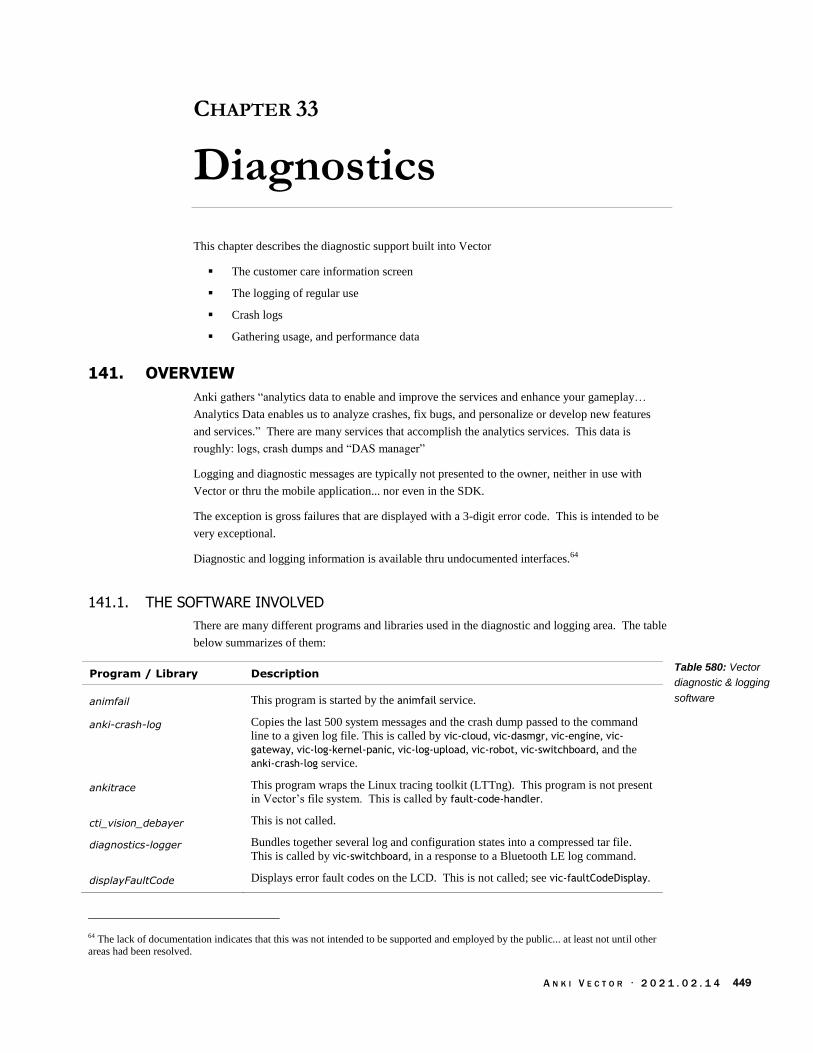
A N K I V E C T O R · 2 0 2 1 . 0 2 . 1 4 449
CHAPTER 33
Diagnostics
This chapter describes the diagnostic support built into Vector
The customer care information screen
The logging of regular use
Crash logs
Gathering usage, and performance data
141. OVERVIEW
Anki gathers “analytics data to enable and improve the services and enhance your gameplay…
Analytics Data enables us to analyze crashes, fix bugs, and personalize or develop new features
and services.” There are many services that accomplish the analytics services. This data is
roughly: logs, crash dumps and “DAS manager”
Logging and diagnostic messages are typically not presented to the owner, neither in use with
Vector or thru the mobile application... nor even in the SDK.
The exception is gross failures that are displayed with a 3-digit error code. This is intended to be
very exceptional.
Diagnostic and logging information is available thru undocumented interfaces.64
141.1. THE SOFTWARE INVOLVED
There are many different programs and libraries used in the diagnostic and logging area. The table
below summarizes of them:
Program / Library Description
animfail This program is started by the animfail service.
anki-crash-log Copies the last 500 system messages and the crash dump passed to the command
line to a given log file. This is called by vic-cloud, vic-dasmgr, vic-engine, vic-
gateway, vic-log-kernel-panic, vic-log-upload, vic-robot, vic-switchboard, and the
anki-crash-log service.
ankitrace This program wraps the Linux tracing toolkit (LTTng). This program is not present
in Vector’s file system. This is called by fault-code-handler.
cti_vision_debayer This is not called.
diagnostics-logger Bundles together several log and configuration states into a compressed tar file.
This is called by vic-switchboard, in a response to a Bluetooth LE log command.
displayFaultCode Displays error fault codes on the LCD. This is not called; see vic-faultCodeDisplay.
64 The lack of documentation indicates that this was not intended to be supported and employed by the public... at least not until other areas had been resolved.
Table 580: Vector
diagnostic & logging
software

A N K I V E C T O R · 2 0 2 1 . 0 2 . 1 4 450
fault-code-clear This clears any pending or displayed faults (by deleting the relevant files). This
allows new fault code to be displayed. This is called by vic-init.sh. Located in /bin
fault-code-handler This is called by the fault-code service. It listens for a fault code, initiates capturing
crash logs, and calls vic-faultCode to display the fault code. Located in /bin
librobotLogUploader.so Sends logs to cloud. This library is employed by libcozmo_engine, vic-gateway and
vic-log-upload.
libosState Used to profile the CPU temperature, frequency, load; the WiFi statistics, and etc.
This is used by libvictor_web_library, vic-anim, and vic-dasmgr.
libwhiskeyToF This unusually named library65 has lots of time of flight sensor diagnostics. This is
present only in version 1.6 and later. This library is employed by libcozmo_engine.
rampost This performs initial communication and version check of the firmware on the
body-board (syscon). This exists within the initial RAM disk, and is called by init.
vic-anim Includes the support for the Customer Care Information Screen. This is started by
the vic-anim service.
vic-crashuploader-init Removes empty crash files, renames the files ending in “.dmp~” to “.dmp”. This is
called by the vic-crashuploader service.
vic-crashuploader A script that sends crash mini-dump files to backtrace.io. This is called by the vic-
crashuploader service.
vic-dasmgr This is started by the vic-dasmgr service.
vic-faultCodeDisplay Displays error fault codes on the LCD. This is called by fault-code-handler.
vic-init.sh Takes the log messages from rampost and places then into the system log, forwards
any kernel panics. This is started by the vic-init service.
vic-log-cat Used to concatenate the logs from /var/log/messages.1.gz and /var/log/messages
vic-log-event A program that is passed an event code in the command line. This is called by
TBD.
vic-log-forward This is called by vic-init.sh
vic-log-kernel-panic This is called by vic-init.sh
vic-log-upload This is called by vic-log-uploader
vic-log-uploader “This script runs as a background to periodically check for outgoing files and
attempt to upload them by calling 'vic-log-upload'.” This is started by the vic-log-
uploader service.
vic-logmgr-upload “This script collects a snapshot of recent log data" into a compressed (gzip) file,
then uploads the file” and software revision “to an Anki Blobstore bucket.” This is
not called.
vic-on-exit Called by systemd after any service stops. This script posts the fault code
associated with the service (if another fault code is not pending) to fault-code-
handler for handling and display.
vic-powerstatus.sh Record every 10 seconds the CPU frequency, temperature and the CPU & memory
usage of the “vic-” processes. This is not called.
(Quotes from Anki scripts.) Support programs are located in /bin, /anki/bin, and /usr/bin
65 Anki has taken great care for squeaky-clean image, even throughout the internal files, so it was a surprise to see one that might appear
named after a rude acronym (WTF). The name is a result of the internal product codes: Whiskey was the code name for a new
generation of Cozmo in development. This was its time of flight (ToF) sensor library, using a modified Vector (called “Spiderface”) as a development prototype. On Whiskey, the time of flight sensor would connect directly to the main processor.
A N K I V E C T O R · 2 0 2 1 . 0 2 . 1 4 451
142. SPECIAL SCREENS AND MODES
Vector has 3 special screens and two special modes. The screens are
A Customer Care Info Screen (CCIS) that can display sensor values and other internal
measures,
A debug screen used to display Vector’s serial number (ESN) and IP address, and
The fault code display which is used to display a 3-digit fault code when there is an
internal failure (this screen is only displayed if there is a fault, and can’t be initiated by an
operator.)
Vector has two special modes
Entering recovery mode, to force Vector use factory software and download replacement
firmware. (This mode doesn’t delete any user data.)
“Factory reset” which erases all user data, and Vector’s robot name
142.1. CUSTOMER CARE INFORMATION SCREEN
Customer Care Info Screen (CCIS). It has a series of screens that display sensor values and other
readings.
See https://www.kinvert.com/anki-vector-customer-care-info-screen-ccis/ for a walk thru
142.2. VECTORS’ DEBUG SCREEN (TO GET INFO FOR USE WITH THE SDK)
Steps to enter the debug screen
1. Place Vector on the charger,
2. Double-click his backpack button,
3. Move the arms up and down
This will display his ESN (serial number) and IP address. The font is much smaller than normal,
and may be hard to read.
142.3. DISPLAYING FAULT CODES FOR ABNORMAL SYSTEM SERVICE EXIT / HANG
If there is a problem while the system is starting or running – such as one of the services exits early
(e.g. crashes) , or it encounters an internal error – a fault code associated with that service is
displayed , and crash information is gathered for later analysis. See Appendix D for fault codes.
The implementation details will be discussed in section 145.6 Fault Code Handler below.
142.4. RECOVERY MODE
Vector includes a recovery mode that is used to force Vector to boot using factory software. The
recovery mode will not delete any user data or software that had previously been installed via
Over-The-Air (OTA) update.
A N K I V E C T O R · 2 0 2 1 . 0 2 . 1 4 452
The recovery mode is intended to help with issues such as Vector failing to boot up using the
regular firmware. He may have been unable to charge (indicated by teal Back Lights), or
encountered other software bugs66.
The application in the recovery mode attempts to download and reinstall the latest software. This
is likely done under the assumption that the firmware may be corrupted, or not the latest, and that a
check for corruption isn’t possible with the read-only filesystems of production software.
142.5. “FACTORY RESET”
Choosing the “Clear User Data” option in Vector’s CCIS erases all user data, including pictures,
faces, and API certificates & tokens. This also clears out the robot name. The Vector will be
given a new robot name when he is set up again.
The menu is implemented in the vic-anim program. When the Clear User Data menu option is
selected and confirmed, triggers the erasing all of the user data when the system shutdowns down
to reboot. First, it creates the file /run/wipe-data and then begins the shutdown and reboot
process. During the system shutdown, the mount-data service will detect the existence of the
/run/wipe-data file and erase the user data (/data) and the switchboard board partitions.
The name “factory reset” is slightly controversial, as this does not truly place Vector into an
identical software state as robot in the factory.
143. BACKPACK LIGHTS
The lights on the backpack are primarily set by Vic-robot, but driven by the body-board. If the
body-board firmware (syscon) is unable to communicate with Vic-robot, the body-board will set the
lights on its own.
144. DIAGNOSTIC COMMANDS
There are several HTTPS commands that are useful for diagnosing errors:
· The connectivity with the cloud can be checked to see if the servers can be reached, if the
authentication (i.e. username and password) is valid, if the server certificate is valid. See
Chapter 15, section 54.1 Check Cloud Connection
· The debug logs can be requested to be sent to the server for analysis. See the Upload
Debug Logs command in Chapter 15, section 54.2 Upload Debug Logs
145. LOGS
Acquiring Logs
Logs can be downloaded to a PC or mobile application using the Bluetooth LE API
The logs can be sent to the server using the Upload Debug Logs API command. See
Chapter 15 section 54.2 Upload Debug Logs
Logs are gathered when a fault-code is raised
Logs are gathered when an Anki program crashes
66 The web page says that are “indicated by a blank screen. If you get a status code between 200-219, recovery mode will also help.”

A N K I V E C T O R · 2 0 2 1 . 0 2 . 1 4 453
145.1. GATHERING LOGS, ON DEMAND
The logs can be requested by issuing a log fetch command via Bluetooth LE. Vic-switchboard
handles the request, delegating the preparation of the log files to diagnostics-logger.
/data/diagnosticsdiagnostics-
logger
Bluetooth
LE App
vic-
switchboad
This utility gathers the following files, archives and compresses them:
File Description
connman-services.txt connmanctl services
dmesg.txt Executes dmesg and captures the standard output.
ifconfig.txt Executes ifconfig wlan0 and captures the standard output.
iwconfig.txt Executes iwconfig wlan0 and captures the standard output.
log.txt Concatenates /var/log/messages.1.gz (uncompressed) and /var/log/messages
netstat-ptlnu.txt Executes netstat -ptlnu and captures the standard output.
ping-anki.txt Ping’s anki.com for connectivity and latency.
ping-gateway.txt Looks up the IP address (using netstat) of the gateway that Vector
is using and pings it for connectivity and latency.
ps.txt Process stats (ps) of Anki’s “Vic” processes
top.txt Executes top -n 1 and captures the standard output.
This utility is triggered by:
Vic-switchboard when issued a log fetch command (via Bluetooth LE).
Vic-gateway when the upload log command is issued
Other
145.2. VIC-LOGMGR-UPLOAD
The vic-logmgr-upload script is not used, but it instructive to examine. When called it copies all of
the messages from /var/log/messages.1.gz and /var/log/messages then sends the compressed
result to the URL given on the command line.
/data/data/
com.anki.victor/
cache/vic-logmgr
vic-logmgr-
uploadvic-log-cat
Anki
blobstore
Figure 133: The
Bluetooth LE based
diagnostics-logger
process
Table 581: Files in the
diagnostics log archive
Figure 134: The vic-
logmgr-upload log
uploader

A N K I V E C T O R · 2 0 2 1 . 0 2 . 1 4 454
145.3. GATHERING LOGS, REGULARLY
The vic-log-uploader service regularly checks for log files to send to a server. The fault code and
crash handlers may place log files into an outgoing folder to be uploaded. The outgoing folder is in
non-volatile memory, so they can be waiting for a reboot before they are sent, if the robot loses
power, has a serious fault, or network access isn’t available.
vic-log-
uploader
/data/data/
com.anki.victor/
cache/outgoing
vic-log-
uploadAWS
The log uploader configuration file is located at:
/anki/etc/vic-log-uploader.env
This path is in the start-up /lib/systemd/system/vic-log-uploader.service file that starts the log
uploader service. This file can have the following fields (if none are set, the log uploader reverts to
these defaults):
Variable Default Description & Notes
VERBOSE 0 If set to 1, extra debugging messages are logged.
VIC_LOG_UPLOADER_FOLDER The path on the local file system to store the logs until they can
be uploaded.
VIC_LOG_UPLOADER_QUOTA_MB 10 The maximum allowed total size of the log files to leave in the
upload folder; the oldest files are removed until the total size is
less than (or equal) to this.
VIC_LOG_UPLOADER_SLEEP_SEC 30 The amount of time between checks for log files.
145.4. OPTING INTO (AND OUT OF) UPLOADING LOGS AND DAS EVENTS
The fault handler and crash uploader also checks for the existence of the following file before
passing logs to vic-log-uploader:
/run/das_allow_upload
This file is intended to indicate – to only exist – if the user accepts uploading diagnostic
information, and to not exist if they have opted out of data collection. If this exists, the crash
minidump traces and log files are captured by fault-crash-handler and the log files are captured vic-
crashuploader, and passed to be uploaded. If it does not exist, the log files are not captured or
uploaded. (vic-crashuploader uploads the crash minidumps either way, but will only included the
logs files allowed.)
This file is created by the DAS-manager (more on its event collection later).
/data/data/com.anki.victor/persistent/dasGlobals.json
This path is specified by the DASConfig.json (more on that in a later section).
This JSON file is a structure with a single key: “dasGlobals”. This in turn dereferences to a
structure with the following fields:
Variable Type Description & Notes
allow_upload boolean If true, the file will be created, and uploads are allowed
Figure 135: The vic-
log-uploader log
upload pipeline
Table 582: The log
uploader configuration
variables
Table 583: The DAS
preferences variables

A N K I V E C T O R · 2 0 2 1 . 0 2 . 1 4 455
profile_id string The Base-64 identifier for the account. If there is no account, it
is an identifier that is made by other means.
This file appears to be downloaded from the JDocs store.
145.5. KERNEL ACTIVITY TRACING (LTTNG)
Vector 1.7 started the use of the Linux Trace Toolkit NG (LTTng). LTTng is configured by the
ankitrace.service to record a variety of events – syscalls, kernel switch, CPU frequency, IRQ’s,
kernel memory management, custom events emitted by Anki programs, and so on. The Anki
applications also register a few probes to add to the traces as they execute.
When a fault occurs, the record of activity is saved for later examination.
Both the service to start the tracing, and to record (on demand) a snapshot of the trace are handled
by the ankitrace script.
145.6. FAULT CODE HANDLER
A fault code can be posted to the fault code handler by a service, based on errors it detects. More
often, a fault code is sent by systemd if one of the service processes it started exits unexpectedly.
The fault code handler receives this code, captures diagnostic information to pass on to Anki
developers to prevent further problems in the future, and invokes vic-faultCodeDisplay to display
the 3 digit code. It then (optionally) restarts the Vic services, or allows the body-board to turn the
system power off, after giving enough time for a person to read the code.
vic-cloud
vic-anim
vic-robot
vic-
faultCodeDisplay
fault-code-
handlervic-on-exitsystemd LCD display
/data/data/
com.anki.victor/
cache/outgoing
Capture kernel
trace
The fault code is sent by writing a string with the fault code to the FIFO file located at:
/run/fault_code
The fault code handler configuration file is located at:
/anki/etc/fault-code-handler.env
This path is in the start-up /lib/systemd/system/fault-code.service file that starts the fault-codes
service.
This configuration file can have the following fields (if none are set, the fault-code-handler reverts
to these defaults):
Variable Default Description & Notes
FAULT_RESTART_COUNT 0 The default count for the number of restarts. The count of
Figure 136: The fault-
code-handler process
Table 584: The fault
code handler
configuration variables

A N K I V E C T O R · 2 0 2 1 . 0 2 . 1 4 456
restarts is loaded from the /run/fault_restart_count file.
FAULT_RESTART_LIMIT 2 Automatic restarts are allowed only if the restart count is less
than this.
FAULT_RESTART_LIMIT_SEC 60 The restart count is cleared after this amount of time has passed.
the /run/fault_restart_count
ON_FAULT_RESTART 0 If set to 1, “Vector will restart” is displayed. Then Vector will
restart (if it hasn’t restarted too many times recently)
ON_FAULT_UPLOAD_LOG 0 If greater than 0, the log data is captured. If this is a developer
build, the log is left on disk; if it isn’t the log is compressed and
placed in the outgoing path.
ON_FAULT_UPLOAD_TRACE 0 If greater than 0, the trace data is captured. If this is a developer
build, the log is left on disk; if it isn’t the log is compressed and
placed in the outgoing path.
TIMEOUT_SIGTERM_SEC 3 This is the period of time to wait for services to stop before
sending them a SIGTERM signal.
TIMEOUT_RESTART_SEC 5 If restarting, wait this number of seconds before initiating the
system restart command.
VERBOSE 0 If set to 1, extra debugging messages are logged.
The fault-code-handler process works as follows:
1. The /run/fault_code FIFO is created by the fault-code.socket service.
2. When there is any input on the FIFO, systemd launches the corresponding fault-
code.service. This launches fault-code-handler with its stdin set to read from the FIFO.
3. Then a line of text is read from the /run/fault_code FIFO, and cleaned up to only contain
only digits. If there are no digits – or the fault code is 0 – it exits.
4. The handler checks to see if the /run/fault_code.pending exists. If so, it exits. This file is
used to tell if the fault-code-handler still handling a fault, possibly while waiting for the
system to be powered off by the body-board.
5. It begins the process of capturing diagnostic traces, and logs for later analysis of the fault;
6. The system services are stopped; depending on the classification of the fault, this may stop
all, or just a few.
7. Updates the counts of restarts, and checks the limit
8. The handler checks to see if /run/fault_code.showing exists. If the
/run/fault_code.showing file exists, the fault display is already showing and another will
not be shown. Otherwise,
a. Then the vic-faultCodeDisplay is executed to display the fault code. The fault
code is passed on the command line.
b. The fault code is placed into /run/fault_code.showing
9. If uploading is enabled, the fault report and diagnostic LTTng traces are copied to the
outgoing queue area.
10. It also takes care to clear out the FIFO.
11. Attempt to restart the system services, after a delay – if that is allowed with this fault
classification, and there have not been too many restarts in an attempt to clear the error.

A N K I V E C T O R · 2 0 2 1 . 0 2 . 1 4 457
The handler counts the number of restarts (of the system services) within a time window; if
there have too many restarts, another one is not performed.
a. If a restart is not allowed, the body-board will eventually power off the system.
12. The /run/fault_code.pending file is removed.
The following files are employed by the fault code handler:
File Description
/run/fault_code.pending The “pending” file allows a second fault – a second attempt to run
fault-code-handler after it has already displayed a fault, but not
been cleared by the restart of the system services. It will still trap
the trace of diagnosticsevents, and may trigger further restarting of
services – or stopping them, forcing the body-board to eventually
remove power.
/run/fault_code.showing The existence of this file is used to allow only a single fault code
to be displayed. It is set to the fault code being displayed.
/run/fault_restart_count This is incremented with each restart, and cleared by a reboot.
/run/fault_restart_uptime This captures the time of the last restart of system services. It is
used to tell if enough time has passed to reset the restart counter.
145.7. CRASH LOGS
The Anki applications are set up to produce small information files when the application crashes.
This is done by the applications using Google breakpad toolkit, which hooks several of the
applications emergency exit signals. When the application crashes, the toolkit captures the key
information in minidump files, which are optionally sent to backtrace.io for analysis.
The vic-crashuploader service regularly checks for log files to send to a server. The outgoing logs
are in non-volatile memory, so they can be waiting for a reboot before they are sent, if the robot
loses power, has a serious fault, or network access isn’t available.
vic-crash
uploader
/data/data/
com.anki.victor/
cache/crashDumps
backtrace.io
The vic-crashuploader configuration file is located at:
/anki/etc/vic-crashuploader.env
This path is in the start-up /lib/systemd/system/vic-crashuploader.service file that starts the fault-
codes service.
This file can have the following fields (if none are set, the crash uploader reverts to these defaults):
Variable Default Description & Notes
VIC_CRASH_FOLDER The path to store crash dump files in
VIC_CRASH_SCRAPE_PERIOD_SEC 30 The number of seconds to sleep between cycles of looking for
crash files to upload.
VIC_CRASH_UPLOADER_KEEP_LATEST
30 The maximum number of crash files to retain; older files are
deleted.
Table 585: Fault code
handler files.
Figure 137: The vic-
crashuploader pipeline
Table 586: The crash
uploader configuration
variables

A N K I V E C T O R · 2 0 2 1 . 0 2 . 1 4 458
VIC_CRASH_UPLOAD_LOG 0 If greater than zero, the log files are also uploaded.
VIC_CRASH_UPLOAD_URL The URL to upload the crash dump files to
The anki-crash-log process works as follows:
1. The anki-crash-log.socket service creates a FIFO file called:
/run/anki-crash-log
2. The anki-crashuploader.service removes old files from the VIC_CRASH_FOLDER and
launches vic-crashuploader.
3. When an Anki application crashes, the breakpad toolkit creates a minidump file in the
VIC_CRASH_FOLDER., then it posts the path to the FIFO file
4. When there is any input on the FIFO, systemd launches the corresponding anki-crash-
log.service. This launches anki-crash-log script with its stdin set to read from the FIFO.
5. This script reads a line of text from the /run/anki-crash-log FIFO, and copies the last 400
messages the system log to file in the same directory.
6. Periodically anki-crashuploader wakes (every VIC_CRASH_SCRAPE_PERIOD_SEC seconds)
and, if upload is allowed, TBD, uploads the file to VIC_CRASH_UPLOAD_URL. (See chapter
17 for more details.)
7. All but the newest VIC_CRASH_UPLOADER_KEEP_LATEST crash files are removed.
146. CONSOLE FILTER
The logging by functional blocks (primarily in Vic-engine) can be configured. The logging
configuration file is located at:
/anki/data/assets/cozmo_resources/ config/engine/console_filter_config.json
This file is organized as dictionary whose key is the host operating system. The “vicos” key is the
one relevant for Vector.67 It dereferences to a structure with the following fields:
Field Type Description & Notes
channels array An array of the channel logging enable structures
levels array An array of logging level enable structures
This “channels” is as an array of structures with the following fields:
Field Type Description & Notes
channel string The name of the channel
enabled boolean True if should log information from the channel, false if not.
67 The other OS key is “osx” which suggests that Vector’s software was development on an OS X platform.
Table 587: The
console filter channel
structure
Table 588: The
channel logging
enable structure

A N K I V E C T O R · 2 0 2 1 . 0 2 . 1 4 459
This “levels” is an array of structures with the following fields:
Field Type Description & Notes
enabled boolean True if should log information at that level, false if not.
level string “event” or “debug”
The features are used as linking mechanisms of the modules. It is likely modules of behavior /
functionality. It is not clear how it all ties together.
Channel enabled Description & Notes
Actions false
AIWhiteboard false
Alexa false
Audio false
Behaviors false
BlockPool false
BlockWorld false
CpuProfiler true
FaceRecognizer false
FaceWorld false
JdocsManager true
MessageProfiler true
Microphones false
NeuralNets false
PerfMetric true
SpeechRecognizer false
VisionComponent false
VisionSystem false
* false
Table 589: The
logging level enable
structure
Table 590: The
channels

A N K I V E C T O R · 2 0 2 1 . 0 2 . 1 4 460
147. USAGE STUDIES AND PROFILING DATA
Anki had ambitions to perform engagement studies and experiments with device settings:
“The Services collect gameplay data such as scores, achievements, and feature usage. The
Services also automatically keep track of information such as events or failures within
them. In addition, we may collect your device make and model, an Anki-generated
randomized device ID for the mobile device on which you run our apps, robot/vehicle ID
of your Anki device, ZIP-code level data about your location (obtained from your IP
address), operating system version, and other device-related information like battery level
(collectively, “Analytics Data”).”
The DAS manager protocol’s version identifier dates to the development of Overdrive. One patent
on their “Adaptive Data Analytics Service” is quite an ambitious plan to tune an improve systems.
“A closed-loop service, referred to as an Adaptive Data Analytics Service (ADAS),
characterizes the performance of a system or systems by providing information describing
how users or agents are operating the system, how the system components interact, and
how these respond to external influences and factors. The ADAS then builds models and/or
defines relationships that can be used to optimize performance and/or to predict the results
of changes made to the system(s). Subsequently, this learning provides the basis for
administering, maintaining, and/or adjusting the system(s) under study. Measurement can
be ongoing, even after the operating parameters or controls of a system under the
administration or monitoring of the ADAS have been adjusted, so that the impact of such
adjustments can be determined. This recursive process of observation, analysis, and
adjustment provides a closed-loop system that affords adaptability to changing operating
conditions and facilitates self-regulation and self-adjustment of systems.”
There is no information on whether this was actually accomplished, or that these techniques were
used in Cozmo or Vector. Anki developed “both batch and real-time dashboards to gain insights
over device and user behavior,” according to their Elemental toolkit literature.
147.1. EVENT TRACING
The DAS manager on Vector and the mobile application posts event such as when an activity
begins, key milestones along the way, and when the activity ends. The events can include extra
parameters such as text and values. In the case of the mobile application, this is the name of each
button pressed, screen displayed, error encountered, and so forth.
Speculated purpose:
To identify how far people got in a process, or what their flow thru an interaction is
To estimate durations of activities, such as onboarding, how long Vector can play between
charge cycles, and how long a charge cycle is.
To identify unusual events (such as errors).
May allow detailed reconstruction of the setup, configuration and interaction

A N K I V E C T O R · 2 0 2 1 . 0 2 . 1 4 461
The event naming pattern is [module name].[some arbitrary name]. When these are logged in
Vector’s text log files they are prefixed with an ‘@’ symbol.68 For examples of DAS events, see
Appendix L.
The vic-dasmgr configuration file is located at:
/anki/data/assets/cozmo_resources/ config/DASConfig.json
This path is in the vic-dasmgr executable. This file can have the following fields:
Variable Default Description & Notes
backup_path
backup_quota 10000000
file_threshold_size 1000000
flush_interval 600
persistent_globals_path
storage_path /run/dasLogs
storage_quota 5000000
transient_globals_path
url The URL to upload the DAS files to
147.2. DAS
The DAS engine uploads JSON files. Each file holds an array of structures with the following
fields:
Field Type Description & Notes
boot_id string
event string The name of the event/error that occurred, or the type of stats
loggedy. Sometimes the event is generic – as with “log.error” –
so the s1 field needs to be examined. Spaces should be trimmed
from the start and end of the field. Some event names are
accidentally logged with a trailing space (e.g.
“rampost.dfu.desired_version”).
feature_run_id string
feature_type string
i1 int64 Extra information, in integer format. Note, for at least one kind
of entry the value domain is 64-bits.
i2 int Extra information, in integer format.
i3 int Extra information, in integer format.
i4 int Extra information, in integer format.
level string “info”, “warning”, “error”, etc.
profile_id string The account profile id... probably tied to jdocs, and token
68 This is a very helpful feature
Table 591: The DAS
manager configuration
variables
Table 592: The DAS
event JSON structure
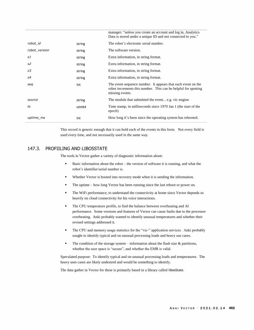
A N K I V E C T O R · 2 0 2 1 . 0 2 . 1 4 462
manager; “unless you create an account and log in, Analytics
Data is stored under a unique ID and not connected to you.”
robot_id string The robot’s electronic serial number.
robot_version string The software version.
s1 string Extra information, in string format.
s2 string Extra information, in string format.
s3 string Extra information, in string format.
s4 string Extra information, in string format.
seq int The event sequence number. It appears that each event on the
robot increments this number. This can be helpful for spotting
missing events.
source string The module that submitted the event... e.g. vic-engine
ts uint64 Time stamp, in milliseconds since 1970 Jan 1 (the start of the
epoch)
uptime_ms int How long it’s been since the operating system has rebooted.
This record is generic enough that it can hold each of the events in this form. Not every field is
used every time, and not necessarily used in the same way.
147.3. PROFIILING AND LIBOSSTATE
The tools in Vector gather a variety of diagnostic information about:
Basic information about the robot – the version of software it is running, and what the
robot’s identifier/serial number is.
Whether Vector is booted into recovery mode when it is sending the information.
The uptime – how long Vector has been running since the last reboot or power on.
The WiFi performance, to understand the connectivity at home since Vector depends so
heavily on cloud connectivity for his voice interactions.
The CPU temperature profile, to find the balance between overheating and AI
performance. Some versions and features of Vector can cause faults due to the processor
overheating. Anki probably wanted to identify unusual temperatures and whether their
revised settings addressed it.
The CPU and memory usage statistics for the “vic-” application services. Anki probably
sought to identify typical and on unusual processing loads and heavy use cases.
The condition of the storage system – information about the flash size & partitions,
whether the user space is “secure”, and whether the EMR is valid.
Speculated purpose: To identify typical and on unusual processing loads and temperatures. The
heavy uses cases are likely undesired and would be something to identify.
The data gather in Vector for these is primarily based in a library called libosState.
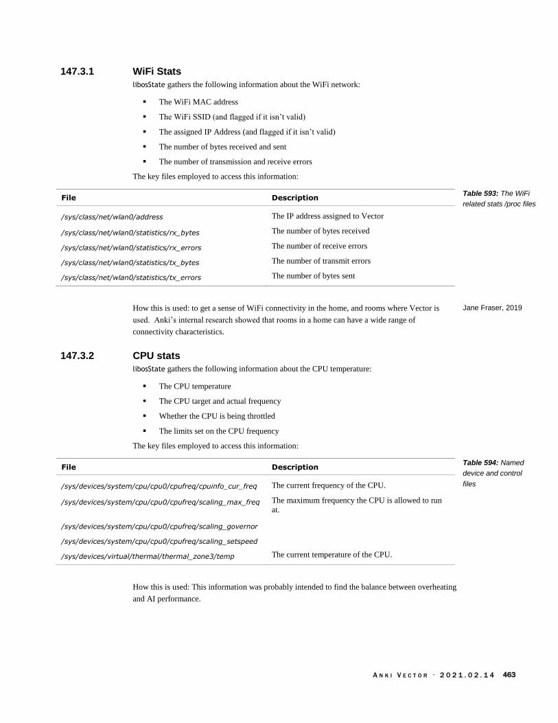
A N K I V E C T O R · 2 0 2 1 . 0 2 . 1 4 463
147.3.1 WiFi Stats
libosState gathers the following information about the WiFi network:
The WiFi MAC address
The WiFi SSID (and flagged if it isn’t valid)
The assigned IP Address (and flagged if it isn’t valid)
The number of bytes received and sent
The number of transmission and receive errors
The key files employed to access this information:
File Description
/sys/class/net/wlan0/address The IP address assigned to Vector
/sys/class/net/wlan0/statistics/rx_bytes The number of bytes received
/sys/class/net/wlan0/statistics/rx_errors The number of receive errors
/sys/class/net/wlan0/statistics/tx_bytes The number of transmit errors
/sys/class/net/wlan0/statistics/tx_errors The number of bytes sent
How this is used: to get a sense of WiFi connectivity in the home, and rooms where Vector is
used. Anki’s internal research showed that rooms in a home can have a wide range of
connectivity characteristics.
147.3.2 CPU stats
libosState gathers the following information about the CPU temperature:
The CPU temperature
The CPU target and actual frequency
Whether the CPU is being throttled
The limits set on the CPU frequency
The key files employed to access this information:
File Description
/sys/devices/system/cpu/cpu0/cpufreq/cpuinfo_cur_freq The current frequency of the CPU.
/sys/devices/system/cpu/cpu0/cpufreq/scaling_max_freq The maximum frequency the CPU is allowed to run
at.
/sys/devices/system/cpu/cpu0/cpufreq/scaling_governor
/sys/devices/system/cpu/cpu0/cpufreq/scaling_setspeed
/sys/devices/virtual/thermal/thermal_zone3/temp The current temperature of the CPU.
How this is used: This information was probably intended to find the balance between overheating
and AI performance.
Table 593: The WiFi
related stats /proc files
Jane Fraser, 2019
Table 594: Named
device and control
files

A N K I V E C T O R · 2 0 2 1 . 0 2 . 1 4 464
147.4. EXPERIMENTS
There is an experiments file; this is in libcozmo-engine as well. Cozmo’s APK has a file with the
same structure. The file has the following high-level structure:
Field Type Description & Notes
meta meta structure A structure that describes what project the experiment applies to
and the versioning info of the structure.
experiments array of experiment structures
An array of experiments, each with their own conditions and
parameters.
The meta structure has the following fields:
Field Type Description & Notes
project_id string “cozmo”69
revision int 1
version int 2
The experiment can be run for a bounded period of time, with an optional period that the
experiment is paused (perhaps for holidays). An experiment structure has the following fields:
Field Type Description & Notes
activation_mode string “automatic”
audience_tags array of TBD
forced_variations array of TBD
key string “report_test_auto”
pop_frac_pct int Portion of the population, as a percentage, that will take part in
this experiment.
pause_time_utc_iso8601 string The time at which to pause the experiment.
resume_time_utc_iso8601 string The time at which to resume the experiment after pausing.
start_time_utc_iso8601 string The date and time that the experiment will commence.
stopt_time_utc_iso8601 string The date and time that the experiment will end.
variations array of variation
version int 0
A variation structure has the following fields:
Field Type Description & Notes
key string One of at least two populations subject to the test: “control” or
“treatment”
pop_fract_pct int Portion of the population, as a percentage, that will be in this
subject group.
69 I suspect that this would have changed once experiments were initiated with Vector
Table 595: The
experiments TBD
structure
Table 596: The meta
JSON structure
Table 597: The
experiment JSON
structure
Table 598: The
variation JSON
structure

A N K I V E C T O R · 2 0 2 1 . 0 2 . 1 4 465
148. REFERENCES & RESOURCES
Anki, Privacy policy, 2018 Oct 5
https://anki.com/en-us/company/privacy.html
DeNeale, Patrick; Tom Eliaz; Adaptive data analytics service, Anki, USPTO
US9996369B2, 2015-Jan-05
Google, Getting started with breakpad
https://chromium.googlesource.com/breakpad/breakpad/+/master/docs/getting_started_with_b
reakpad.md
This gives an overview of the break pad process of capture crash information as mini dumps,
and forwarding it to centralize servers for analysis
The LTTng Project, The LTTng Documentation, 2020 Aug 5
https://lttng.org/docs/v2.12/
Microsoft, minidump files
https://docs.microsoft.com/en-us/windows/win32/debug/minidump-files
https://docs.microsoft.com/en-us/windows/win32/api/minidumpapiset/
Built on — extending slightly — the mini dump format developed by Microsoft
os-release — Operating system identification
https://www.freedesktop.org/software/systemd/man/os-release.html
Describes the /etc/os-version and /etc/os-version-rev files

A N K I V E C T O R · 2 0 2 1 . 0 2 . 1 4 466
[This page is intentionally left blank for purposes of double-sided printing]

A N K I V E C T O R · 2 0 2 1 . 0 2 . 1 4 467
References &
Resources
Note: most references appear in the margins, significant references will appear at the end of their
respective chapter.
149. CREDITS Credit and thanks to Anki who made Vector possible; C0RE, Melanie T for access to the flash
partitions, file-systems, decode keys, board shots, unusual LED codes, information on the
electronics, and OTA URLs. Wire/Kerigan Creighton for board shots, the Project Victor website
& public relations, finding the web-visualization tool, OTA URLs, identifying the valuable OTA
versions, checking the compatibility with Cozmo animations and fun with boot animations. Fictiv
for board shots. (The board shots helped identify parts on the board and inter-connection on the
board.) GooeyChickenman for the github repository. Cyril Peponet for aboot analysis, finding
OTA v1.7, and pointing me valuable past discord postings. Alexander Entinger for body-board
connector signal information. Paul Brett for Cube Bluetooth LE information. HSReina for Vector
Bluetooth LE protocol information. Wayne Venables for crafting a C# version of the SDK.
Silvarius/Silvarius613 & nammo for info on the other Anki products that were under development.
nammo for information on error codes, shaft encoders, battery life, signal processing, and much
more. Ben Gabaldon for information on Wwise craftsmanship. Mike Huller for catching several
typos. Thanks to Mike Corlett for helping me understand more of the token passing scheme.
Several drawings were adapted from Steph Dere, and Jesse Easley’s twitter & instagram.
Thank-you Frien and Wire for posting JSON intents, and keeping the communities together.
Cyke for alerting people to interesting updates.
Thank-you to Digital Dream Labs (DDL) for continuing support for Vector; DDL and Drew
Zhrodague for providing error tables and cloud information.
150. REFERENCE DOCUMENTATION AND RESOURCES
150.1. ANKI
Anki, Vector Quick Start Guide, 293-00036 Rev: B, 2018
Anki, Vector Pillars, 2018
Casner, Daniel, Sensor Fusion in Consumer Robots, Embedded Vision Summit, 2019 May
https://www.embedded-vision.com/platinum-members/embedded-vision-alliance/embedded-
vision-training/videos/pages/may-2019-embedded-vision-summit-casner
https://www.youtube.com/watch?v=NTU1egF3Z3g
Casner, Daniel; Lee Crippen, Hanns Tappeiner, Anthony Armenta, Kevin Yoon; Map Related
Acoustic Filtering by a Mobile Robot, Anki, US Patent 0212441 A1, 2019 Jul 11
Fraser, Jane, IoT: How it Changes the Way We Test, Spring 2019 Software Test Professionals
Conference, 2019 Apr 3

A N K I V E C T O R · 2 0 2 1 . 0 2 . 1 4 468
https://spring2019.stpcon.com/wp-content/uploads/2019/03/Fraser-IoT-How-it-changes-the-
way-we-test-updated.pdf
Jameson, Molly; Daria Jerjomina; Cozmo: Animation pipeline for a physical robot, Anki, 2017
Game Developers conference
Kaiser (Anki), (Cozmo) Code Lab Block Glossary, 2017 Dec
https://forums.anki.com/t/code-lab-block-glossary/10958
Stein, Andrew; Making Cozmo See, Embedded Vision Alliance, 2017 May 25
https://www.slideshare.net/embeddedvision/making-cozmo-see-a-presentation-from-anki
https://youtu.be/Ypz7sNgSzyI
150.2. OTHER
cozmopedia.org
Crowe, Steven, Anki was developing security robots before shutdown, The Robot Report, 2020 Feb
25
https://www.therobotreport.com/anki-developing-security-robots-before-shutdown/
Easley, Jesse
https://fatralla.tumblr.com/
FCC ID 2AAIC00010 internal photos
https://fccid.io/2AAIC00010
FCC ID 2AAIC00011 internal photos
https://fccid.io/2AAIC00011
FPL, FlatBuffers
https://google.github.io/flatbuffers/
Kinvert, Anki Vector Customer Care Info Screen (CCIS)
https://www.kinvert.com/anki-vector-customer-care-info-screen-ccis/
Sriram, Swetha, Anki Vector Robot Teardown, Fictiv, 2019 Aug 6
https://www.fictiv.com/blog/anki-vector-robot-teardown
Tenchov, Kaloyan; PyCozmo
https://github.com/zayfod/pycozmo/tree/master/pycozmo
Venable, Wayne; Anki.Vector.SDK
https://github.com/codaris/Anki.Vector.SDK
https://github.com/codaris/Anki.Vector.Samples
https://weekendrobot.com/
Zaks, Mazim FlatBuffers Explained, 2016-Jan-30
https://github.com/mzaks/FlatBuffersSwift/wiki/FlatBuffers-Explained
150.3. QUALCOMM Although detailed documentation isn’t available for the Qualcomm APQ8009, there is
documentation available for the sibling APQ8016 processor.
Qualcomm, APQ8016E Application Processor Tools & Resources,
https://developer.qualcomm.com/hardware/apq-8016e/tools
Qualcomm, DragonBoard™ 410c based on Qualcomm® Snapdragon™ 410E processor ADB
Debugging Commands Guide, LM80-P0436-11, Rev C, 2016 Sep
lm80-p0436-11_adb_commands.pdf
Qualcomm, DragonBoard™ 410c based on Qualcomm® Snapdragon™ 410E processor Software
Build and Installation Guide, Linux Android, LM80-P0436-2, Rev J, 2016 Dec
lm80-p0436-2_sw-build-and-install_gd_linux_android_dec2016.pdf

A N K I V E C T O R · 2 0 2 1 . 0 2 . 1 4 469
Appendices
Robots enjoy large, properly-formatted data files (and flowers from their sweetie). We can’t
replicate large files here but we can give large, well-formatted tables telling where to find those
large data files, and consolidating other useful details – details that would distract from the main
narrative.
ABBREVIATIONS, ACRONYMS, & GLOSSARY. This appendix provides a gloss of terms,
abbreviations, and acronyms.
TOOL CHAIN. This appendix lists the tools known or suspected to have been used by Anki to
create, and customize the Vector, and for the servers. Tools that can be used to analyze
Vector.
ALEXA MODULES. This appendix describes the modules used by the Alexa client
FAULT AND STATUS CODES. This appendix provides describes the system fault codes, and
update status codes.
BODY-BOARD CONNECTOR AND PIN MAP. This appendix lists the electrical connections on the
body-board.
FILE SYSTEM. This appendix lists the key files that are baked into the system.
BLUETOOTH LE SERVICES & CHARACTERISTICS. This appendix provides information on the
Bluetooth LE interface GUIDs to the companion Cube, and to Anki Vector.
SERVERS. This appendix provides the servers that the Anki Vector and App contacts
FEATURES. This appendix enumerates the Vector OS “features” that can be enabled and
disabled; and the AI behavior’s called “features.”
PHRASES. This appendix reproduces the phrases that the Vector keys off of.
EMOTION EVENTS. This appendix provides a list of the emotion events that Vector internally
responds to.
DAS EVENTS. This appendix describes the identified DAS events
PLEO. This appendix gives a brief overview of the Pleo animatronic dinosaur, an antecedent
with many similarities.

A N K I V E C T O R · 2 0 2 1 . 0 2 . 1 4 470
[This page is intentionally left blank for purposes of double-sided printing]

A N K I V E C T O R · 2 0 2 1 . 0 2 . 1 4 471
APPENDIX A
Abbreviations,
Acronyms, Glossary
Abbreviation / Acronym
Phrase
ADC analog to digital converter
AG animation group
ALSA advanced Linux sound architecture
APQ application processor Qualcomm (used when there is no modem
in the processor module)
ASR automatic speech recognition
AVS Alexa Voice Service
BIN binary file
BMS battery management system
BNK AudioKinetic sound bank file
CCIS customer care information screen
CLAD C-like abstract data structures
CLAHE contrast-limited adaptive histogram equalization
CNN convolution neural network
CRC cyclic redundancy check
CSI Camera serial interface
DAS unknown (diagnostic/data analytics service?)
DFU device firmware upgrade
DTTB Dance to the beat
DVT design validation test
EEPROM electrical-erasable programmable read-only memory
EMR electronic medical record
ESD electro-static discharge
ESN electronic serial number
EVT engineering validation test
FBS flat buffers
FDE full disc encryption
FFT fast Fourier transform
Table 599: Common
acronyms and
abbreviations
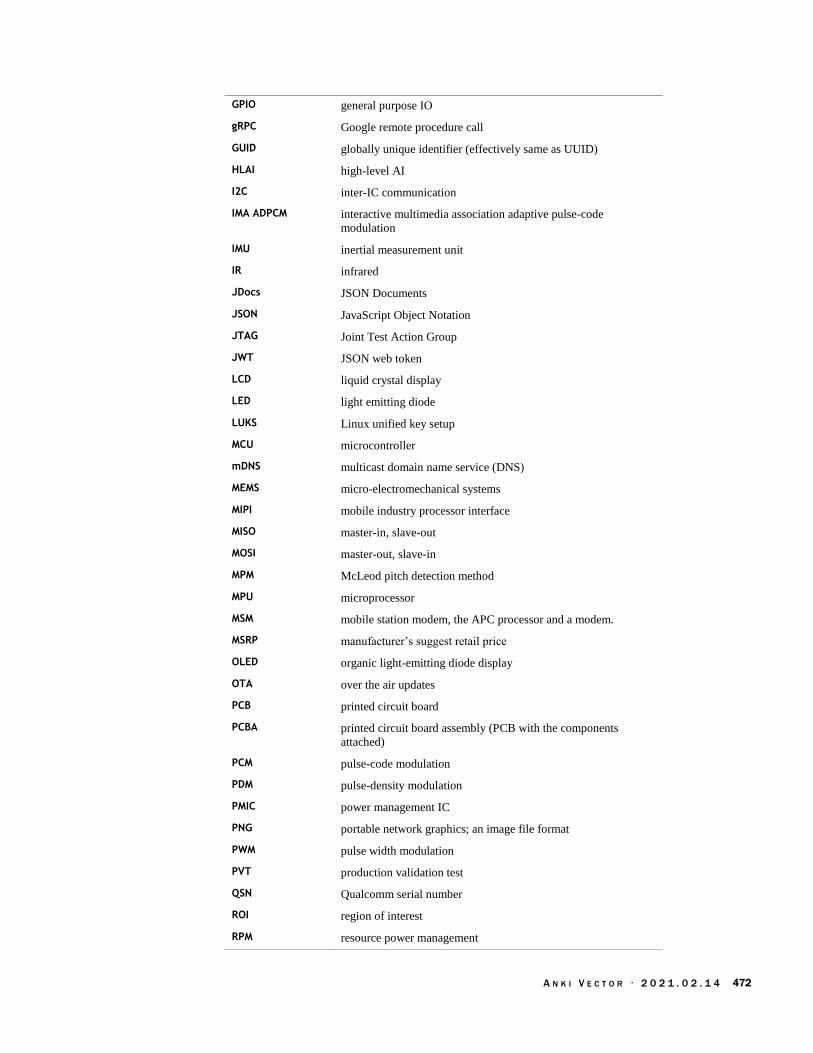
A N K I V E C T O R · 2 0 2 1 . 0 2 . 1 4 472
GPIO general purpose IO
gRPC Google remote procedure call
GUID globally unique identifier (effectively same as UUID)
HLAI high-level AI
I2C inter-IC communication
IMA ADPCM interactive multimedia association adaptive pulse-code
modulation
IMU inertial measurement unit
IR infrared
JDocs JSON Documents
JSON JavaScript Object Notation
JTAG Joint Test Action Group
JWT JSON web token
LCD liquid crystal display
LED light emitting diode
LUKS Linux unified key setup
MCU microcontroller
mDNS multicast domain name service (DNS)
MEMS micro-electromechanical systems
MIPI mobile industry processor interface
MISO master-in, slave-out
MOSI master-out, slave-in
MPM McLeod pitch detection method
MPU microprocessor
MSM mobile station modem, the APC processor and a modem.
MSRP manufacturer’s suggest retail price
OLED organic light-emitting diode display
OTA over the air updates
PCB printed circuit board
PCBA printed circuit board assembly (PCB with the components
attached)
PCM pulse-code modulation
PDM pulse-density modulation
PMIC power management IC
PNG portable network graphics; an image file format
PWM pulse width modulation
PVT production validation test
QSN Qualcomm serial number
ROI region of interest
RPM resource power management

A N K I V E C T O R · 2 0 2 1 . 0 2 . 1 4 473
RRT rapidly-expanding random tree
RSSI received signal strength indicator
SCLK (I2C) serial clock
SDA (I2C) serial data
SDK software development kit
SHK silicon-based hardware key
SLAM simultaneous localization and mapping
SOC system on a chip
SPAD single photon avalanche diode
SPI serial-peripheral interface
SSH secure shell
SSID service set identifier (the name of the Wifi network)
STM32 A microcontroller family from ST Microelectronics
SWD single wire debug
SYSCON system controller
TAR tape archive file
TTS text to speech
UART universal asynchronous receiver/transmitter
USB universal serial bus
UUID universally unique identifier (effectively same as GUID)
vic short for Victor (Vector’s working name)
WEM AudioKinetic Wwise Encoded Media. (a type of sound file)
Phrase Description
A* A path finding algorithm
aboot The Android boot-loader used to launch Vector’s linux system.
accelerometer A sensor used to measure the angle of Vector’s head, and acceleration (change in
velocity).
animation A scripted “sequence of highly coordinated movements, faces, lights, and sounds
… to demonstrate an emotion or reaction.”
animation trigger name An identifier of a group of related animations; Vector “pick[s] .. [an] actual
animations to play based on Vector’s mood or emotion, or with random
weighting. Thus playing the same trigger twice may not result in the exact same
underlying animation playing twice.”
attitude Vector’s orientation, esp relative to the direction of travel
autocorrelation A technique to find how repetitive a signal is; it works by finding how much one
has to shift version of the signal before it (mostly) matches the original signal
again.
backpack board The circuit board in Vectors head with lights, push button, microphones and
touch sensor
Table 600: Glossary
of common terms and
phrases

A N K I V E C T O R · 2 0 2 1 . 0 2 . 1 4 474
beam forming A technique using multiple microphones to listen to a single speaker by
selectively paying attention to sound only coming from that direction.
behavior Behaviors represent a complex task [that] may include combinations of
animation, path planning or other functionality. Examples include” driving to the
charger, set the lift height, etc.
behavior tree A decision tree that decides if a behavior can run or can no longer run, which
related behaviors to start, and the parameter settings to run the behavior with.
body board The circuit board in Vector’s belly that manages the battery and drives the motors
boot loader A piece of software used to load and launch the application software.
C-like abstract data structure (CLAD)
Anki’s phrase for how they pack information into fields and values with a defined
binary format. “Any data [passed] over the wire, [is] define[d with] enums,
structures and messages in “.clad” files.. [with a] syntax [that] looks a lot like C
structs. [A tool] auto-generate[s] Python, C++ and C# code for each of these
structures, along with code to serialize and deserialize to efficiently packed byte
streams of data.” 70 (FlatBuffers are used for the same purpose, but were not
available when CLAD was developed.)
capacitive touch A type of sensing where light contact, such as touch, is detected without requiring
pressing a mechanism.
cascade Applies a series of fast to compute filters and classifiers to detect low-level
features and identify things like faces.
cepstrum A way of using the frequency spectrum to analyze a voice.
certificate Vector generates an SSL certificate that can be used for the secure
communications.
characteristic (Bluetooth LE)
A key (or slot) that holds a value in the services key-value table. A characteristic
is uniquely identified by its UUID.
client token A string token provided by Vector that is passed with each SDK command.
control Responsible for motors and forces to move where and how it is told to. (smooth
arcs)
cooldown A period of time after an action, animation, or behavior has run before it can be
run again. see also hold-off timer
D*-lite A path-finding algorithm
decimation The amount (or ratio) that something is down sampled by.
delocalization “Whenever Vector no longer knows where he is – e.g. when he's picked up,” or
falls.
device mapper verity (dm-verity)
A feature of the Linux kernel that checks the boot and RAM file systems for
alteration, using signed keys
electronic medical record A software record of Vector’s serial number, model, lot code, manufacturing &
test dates, and other information. This is stored in flash.
electronic serial number Vector’s serial number, but the copy that is in his electronic medical record.
entitlement An entitlement is a family of features or resources that the program or owner is
allowed to use.
face detection The ability to realize that there is a face in the image, and where it is
face recognition The ability to know the identity of a face seen.
feature flags aka feature toggle
A setting that enables and disables features, especially those still in development.
This allows developing the code and integrating its structure before the module or
function is completely ready. Otherwise it is very difficult to keep the different
70 https://forums.anki.com/t/what-is-the-clad-tool/102/3

A N K I V E C T O R · 2 0 2 1 . 0 2 . 1 4 475
branches of development in sync and merge them when the feature is ready.
field of view How wide of an area in the world that the camera can see
firmware A type of software held (and usually executed from) in ROM or flash. It may
have a (minimal) operating system, but often does not.
flash A type of persistent (non-volatile) storage media.
guidance Builds the desired path
gyroscope A sensor that is used to measure how fast Vector is turning (the angular velocity)
along its x, y, and z axes.
Haar feature Facial features picked out using Haar wavelets
Haar wavelet A fast, low-cost that can used to pick out (or recognize) simple features in an
image.
habitat A small area for Vector to drive around in while alone, without accidentally
driving off the edge or getting lost. Sold as “Vector Space”
head board The circuit board in Vector’s head with the main processor, WiFi (and Bluetooth
LE), camera, speaker, etc.
hold-off timer a timer that prevents another trigger or event for a period of time (after the
previous one). see also cool down.
hotword aka wake word
inertial measurement unit
The combination of an accelerometer and gyroscope to measure linear
acceleration and rotational velocity.
inner node A node in a tree data structure that does links to other nodes below it. Often it
does not hold any other information.
intent An intent is an internal code (and accompanying structure) that is used to
represent the how to respond to the question or other phrases spoken by a person.
It may represent the action requested, an answer to a query, or an action that
emotionally responds to what was said.
JSON web token71 A compressed, encoded JSON structure that hold a small amount of data (like a
cookie), and some meta-information about how long the token is valid for.
Kalman filter Used to merge two or more noisy signals together to estimate a proper signal.
leaf node A node in a tree data structure that does not link to any other nodes below it. It
holds the information that was being looked up.
navigation Knowing where it is in the map
nonce An initially random number, incremented after each use.
odometry Estimate motion – displacement and rotation – from inertial measurement units
and wheel & track rotation.
path planning Forms smooth arcs and line segments to move in around an environment to avoid
collisions, blocked paths, and cliffs. This is often used to navigate from point A
to point B.
playpen The playpen is a testing area with ramps, barriers, camera targets at a variety of
angles, cube and a charging station.
playpen test The playpen test is a check of the robots sensors, camera calibration, motor
function, microphone and a check over his overall functions. During testing,
Vector’s is checked for correct function: that he can correctly navigate, detect
cliffs, see markers (getting their type and size correct), dock, and charge.
pose The position and orientation of an object relative to a coordinate system
71 https://en.wikipedia.org/wiki/JSON_Web_Token

A N K I V E C T O R · 2 0 2 1 . 0 2 . 1 4 476
power source Where the electric energy used to power Vector comes from.
quad-tree A way of compressing a 2D map down into regions.
rapidly-expanding random tree
A path-finding algorithm
recovery mode A separate, independent operating system that Vector can boot into for purposes
of downloading software to replace a damaged partition.
robot name Vector’s robot name looks like “Vector-E5S6”. It is “Vector-” followed by a 4
letters and numbers.
serial number A unique number that is stamped on Vector’s hardware (on the bottom) and in his
electronic medical record.
service (Bluetooth LE) A key-value table grouped together for a common purpose. A service is uniquely
identified by its UUID.
session token A string token provided by the Anki servers that is passed to Vector to
authenticate with him and create a client token.
silicon-based hardware key
This is a key that is unique to each processor – it is programmed by blowing
fuses during manufacture – and is used to check the signing by secure boot and
TrustZone functions.
simultaneous localization and mapping
A vision-based technique for building a map of the immediate world for purposes
of positioning oneself within it and detecting relative movements.
software Software is distinct from firmware in that is often loaded from external storage to
be run in RAM, and is based on dynamic linking, allowing the use of other
(replaceable) software elements. It does not access hardware directly; instead it
employs sophisticated features of the operating system.
system controller (syscon)
The name of the body-board microcontroller, and the firmware program running
on it.
tempo The pace of music, in beast per second
text to speech A process of reading aloud a word, phrase, sentence, etc.
trigger word aka wake word
Trust Zone A security mode on ARM processor where privileged/special code is run. This
includes access to encryption/decryption keys.
universally unique identifier (UUID)
A 128bit number that is unique. (effectively same as GUID)
vocoder A sound effect that analyzes and transforms a voice; in this case to give Vector
his unique vocal sound.
wake word The phrase (“Hey, Vector”) used to activate Vector so that he will respond to
spoken interaction.
Quotes are from Anki SDK.
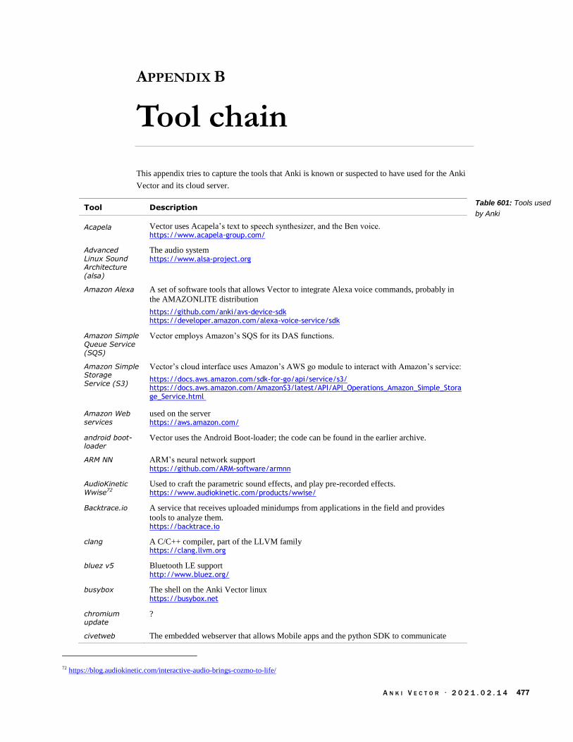
A N K I V E C T O R · 2 0 2 1 . 0 2 . 1 4 477
APPENDIX B
Tool chain
This appendix tries to capture the tools that Anki is known or suspected to have used for the Anki
Vector and its cloud server.
Tool Description
Acapela Vector uses Acapela’s text to speech synthesizer, and the Ben voice. https://www.acapela-group.com/
Advanced Linux Sound Architecture (alsa)
The audio system https://www.alsa-project.org
Amazon Alexa A set of software tools that allows Vector to integrate Alexa voice commands, probably in
the AMAZONLITE distribution
https://github.com/anki/avs-device-sdk https://developer.amazon.com/alexa-voice-service/sdk
Amazon Simple Queue Service (SQS)
Vector employs Amazon’s SQS for its DAS functions.
Amazon Simple Storage Service (S3)
Vector’s cloud interface uses Amazon’s AWS go module to interact with Amazon’s service:
https://docs.aws.amazon.com/sdk-for-go/api/service/s3/ https://docs.aws.amazon.com/AmazonS3/latest/API/API_Operations_Amazon_Simple_Storage_Service.html
Amazon Web services
used on the server https://aws.amazon.com/
android boot-loader
Vector uses the Android Boot-loader; the code can be found in the earlier archive.
ARM NN ARM’s neural network support https://github.com/ARM-software/armnn
AudioKinetic Wwise72
Used to craft the parametric sound effects, and play pre-recorded effects. https://www.audiokinetic.com/products/wwise/
Backtrace.io A service that receives uploaded minidumps from applications in the field and provides
tools to analyze them. https://backtrace.io
clang A C/C++ compiler, part of the LLVM family https://clang.llvm.org
bluez v5 Bluetooth LE support http://www.bluez.org/
busybox The shell on the Anki Vector linux https://busybox.net
chromium update
?
civetweb The embedded webserver that allows Mobile apps and the python SDK to communicate
72 https://blog.audiokinetic.com/interactive-audio-brings-cozmo-to-life/
Table 601: Tools used
by Anki

A N K I V E C T O R · 2 0 2 1 . 0 2 . 1 4 478
with Vector. https://github.com/civetweb/civetweb
connman Connection manager for WiFi https://01.org/connman
Eigen A linear algebra library
http://eigen.tuxfamily.org/
gemmlowp A low-precision general matrix multiplication library
https://github.com/google/gemmlowp
GNU C Compiler (gcc)
GCC version 4.9.3 was used to compile the kernel
golang Go is used on the server applications, and (reported) some of Vector’s internal software.
Google Breakpad
Google Breakpad is used to generate tracebacks and mini-dump files of programs that crash.
Results are sent to htttp://backtrace.io https://chromium.googlesource.com/breakpad/breakpad
Google FlatBuffers
Google FlatBuffers is used to encode the animation data structures. “It is similar to protocol
buffers, but the primary difference is that FlatBuffers does not need a parsing/unpacking
step to a secondary representation before you can access data, often coupled with per-object
memory allocation. Also, the code footprint of FlatBuffers is an order of magnitude smaller
than protocol buffers”73 https://github.com/google/flatbuffers
Google Protobuf
Google’s Protobuf interface-description language is used to describe the format/encoding of
data sent over gRPC to and from Vector. This is used by mobile and python SDK, as well
as on the server. https://developers.google.com/protocol-buffers
Google RPC (gRPC)
A “remote procedure call” standard, that allows mobile apps and the python SDK to
communicate with Vector. https://grpc.io/docs/quickstart/cpp/
hdr-histogram This is a library used to support gathering histograms over a potentially wide range. It is
most likely used when gathering stats about internet access speeds, and equalizing images from the camera. https://github.com/HdrHistogram/HdrHistogram
libsodium Cryptography library suitable for the small packet size in Bluetooth LE connections. Used
to encrypt the mobile applications Bluetooth LE connection with Vector. https://github.com/jedisct1/libsodium
linux, yocto74 The family of linux distribution used for the Anki Vector
(v3.18.66)
linux unified key storage (LUKS)
This is used to protect the private keys and user data.
Maya A character animation tool set, used to design the look and movements of Cozmo and
Vector. The tool emitted the animation scripts.
mpg123 A MPEG audio decoder and player. This is needed by Alexa; other uses are unknown. https://www.mpg123.de/index.shtml
ogg vorbis Audio codec https://xiph.org/vorbis
Omron OKAO Vision
Vector uses the Omron Okao Vision library for face recognition and tracking. https://plus-sensing.omron.com/technology/position/index.html
open CV Used for the first-level image processing – to locate faces, hands, and possibly accessory
symbols. https://opencv.org/
73 https://nlp.gitbook.io/book/tensorflow/tensorflow-lite 74 https://www.designnews.com/electronics-test/lessons-after-failure-anki-robotics/140103493460822
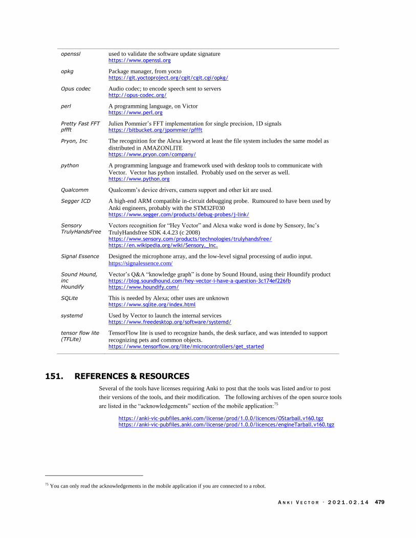
A N K I V E C T O R · 2 0 2 1 . 0 2 . 1 4 479
openssl used to validate the software update signature https://www.openssl.org
opkg Package manager, from yocto https://git.yoctoproject.org/cgit/cgit.cgi/opkg/
Opus codec Audio codec; to encode speech sent to servers http://opus-codec.org/
perl A programming language, on Victor https://www.perl.org
Pretty Fast FFT pffft
Julien Pommier’s FFT implementation for single precision, 1D signals https://bitbucket.org/jpommier/pffft
Pryon, Inc The recognition for the Alexa keyword at least the file system includes the same model as
distributed in AMAZONLITE https://www.pryon.com/company/
python A programming language and framework used with desktop tools to communicate with
Vector. Vector has python installed. Probably used on the server as well. https://www.python.org
Qualcomm Qualcomm’s device drivers, camera support and other kit are used.
Segger ICD A high-end ARM compatible in-circuit debugging probe. Rumoured to have been used by
Anki engineers, probably with the STM32F030 https://www.segger.com/products/debug-probes/j-link/
Sensory TrulyHandsFree
Vectors recognition for “Hey Vector” and Alexa wake word is done by Sensory, Inc’s
TrulyHandsfree SDK 4.4.23 (c 2008) https://www.sensory.com/products/technologies/trulyhandsfree/ https://en.wikipedia.org/wiki/Sensory,_Inc.
Signal Essence Designed the microphone array, and the low-level signal processing of audio input.
https://signalessence.com/
Sound Hound, inc Houndify
Vector’s Q&A “knowledge graph” is done by Sound Hound, using their Houndify product https://blog.soundhound.com/hey-vector-i-have-a-question-3c174ef226fb https://www.houndify.com/
SQLite This is needed by Alexa; other uses are unknown https://www.sqlite.org/index.html
systemd Used by Vector to launch the internal services https://www.freedesktop.org/software/systemd/
tensor flow lite (TFLite)
TensorFlow lite is used to recognize hands, the desk surface, and was intended to support
recognizing pets and common objects. https://www.tensorflow.org/lite/microcontrollers/get_started
151. REFERENCES & RESOURCES
Several of the tools have licenses requiring Anki to post that the tools was listed and/or to post
their versions of the tools, and their modification. The following archives of the open source tools
are listed in the “acknowledgements” section of the mobile application:75
https://anki-vic-pubfiles.anki.com/license/prod/1.0.0/licences/OStarball.v160.tgz https://anki-vic-pubfiles.anki.com/license/prod/1.0.0/licences/engineTarball.v160.tgz
75 You can only read the acknowledgements in the mobile application if you are connected to a robot.

A N K I V E C T O R · 2 0 2 1 . 0 2 . 1 4 480
APPENDIX C
Alexa modules
This Appendix outlines the modules used by the Alexa client built into Vector (using the Alexa
Client SDK). Alexa’s modules connect together like so:
Alexa’s modules include:
Library Description & Notes
libACL.so Alexa Communication Library. “Serves as the
main communications channel between the device
and the Alexa Voice Service.”
libAIP.so Audio Input Processor. “Handles the audio input to
Alexa Voice Service from on-device microphones,
remote microphones and other audio input
sources.”
libADSL.so Alexa Directive Sequencer Library (Directive
Router, Processor, Sequencer; Message
Interpreter).
libAFML.so Activity Focus Manager Library, including Audio
Activity Tracker, Visual Activity tracker.
“Prioritizes the channel inputs and outputs as
specified by the AVS Interaction Model”
libAlerts.so Alexa alert scheduler; “The interface for setting,
stopping, and deleting timers and alarms.”
libAudioPlayer.so Alexa’s audio player. “The interface for managing
and controlling audio playback.”
Figure 138: Alexa’s
function blocks
(image courtesy
Amazon)
Table 602: Alexa files
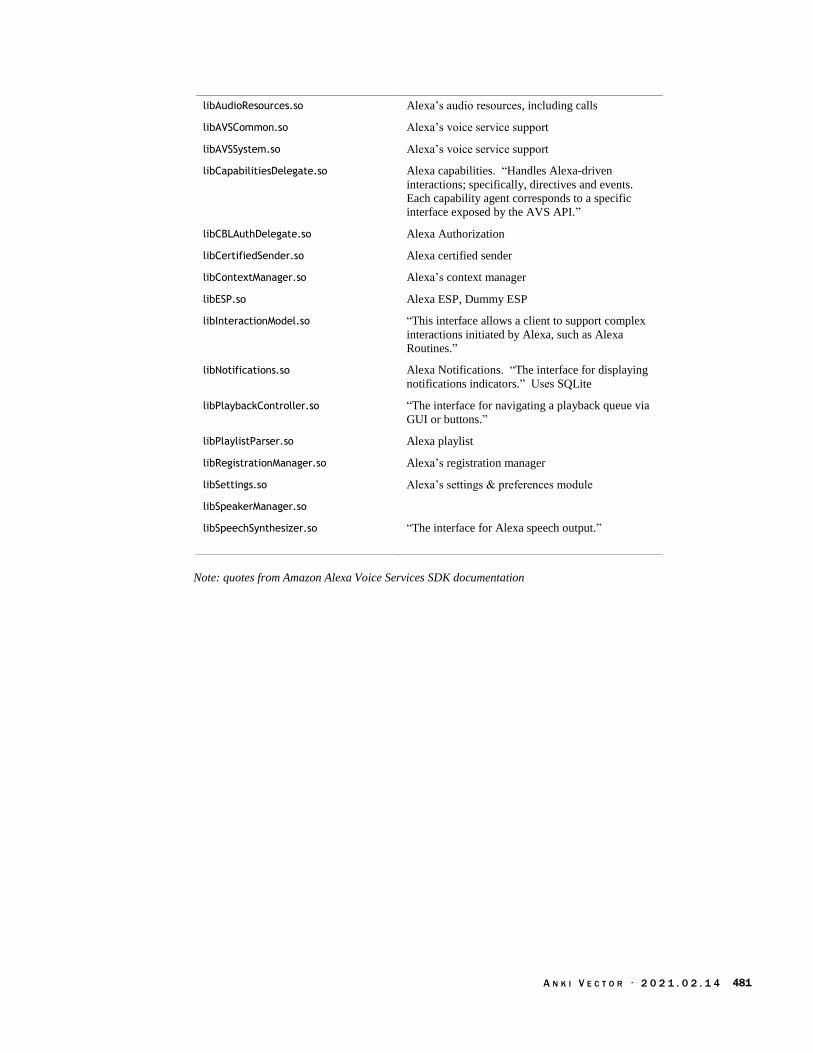
A N K I V E C T O R · 2 0 2 1 . 0 2 . 1 4 481
libAudioResources.so Alexa’s audio resources, including calls
libAVSCommon.so Alexa’s voice service support
libAVSSystem.so Alexa’s voice service support
libCapabilitiesDelegate.so Alexa capabilities. “Handles Alexa-driven
interactions; specifically, directives and events.
Each capability agent corresponds to a specific
interface exposed by the AVS API.”
libCBLAuthDelegate.so Alexa Authorization
libCertifiedSender.so Alexa certified sender
libContextManager.so Alexa’s context manager
libESP.so Alexa ESP, Dummy ESP
libInteractionModel.so “This interface allows a client to support complex
interactions initiated by Alexa, such as Alexa
Routines.”
libNotifications.so Alexa Notifications. “The interface for displaying
notifications indicators.” Uses SQLite
libPlaybackController.so “The interface for navigating a playback queue via
GUI or buttons.”
libPlaylistParser.so Alexa playlist
libRegistrationManager.so Alexa’s registration manager
libSettings.so Alexa’s settings & preferences module
libSpeakerManager.so
libSpeechSynthesizer.so “The interface for Alexa speech output.”
Note: quotes from Amazon Alexa Voice Services SDK documentation

A N K I V E C T O R · 2 0 2 1 . 0 2 . 1 4 482
APPENDIX D
Fault and status codes
The following are system status codes that may be produced during startup (Quotes from “Anki
Vector Error Codes”):
Code Meaning
1..10 Systemd failed…?
1 “Switchboard: unknown status”
2 “Switchboard: [Over the Air Update is] in progress ”
3 “Switchboard: [Over the Air Update has] completed”
4 “Switchboard: rebooting”
5 “Switchboard: other [Over the Air Update] error”
10 “OS: Unknown system error”
001-099 Playpen
100-199 Error related to the body-board (syscon)
200-219 Software update status codes, see table below
220-299 Error codes in the range of 220-299 refer to problems from the software
processes within Vector’s OS
300-799 Error codes in the range of 300-799 refer to problems expected during factory
tests.
700 The robot was shutdown because the button was pressed.
701 The gyroscope sensor is out of range or failed (it wasn’t able to calibrate), so
the robot shutdown.
702 The robot was shutdown because the battery voltage was too low.
703-704 Internal sensor out of range or failed.
705 The robot was shutdown because the battery was too hot to safely operate.
800-999 Error codes in the range of 800-999 refer to “power on self check” failures.
800 Vic-anim was unable to start or crashed.
801 The process to update the cube firmware failed.
840 The camera calibration is missing.
850 There is a problem with the cloud certificate
851 There is a problem with the cloud token store
852 There is a problem reading the cloud electronic serial number (ESN).
870 The front right MEMS microphone failed during power-on self test.
871 The front left MEMS microphone failed during power-on self test.
872 The back right MEMS microphone failed during power-on self test.
873 The back left MEMS microphone failed during power-on self test.
890 The front right cliff sensor failed during power-on self test.
891 The front left cliff sensor failed during power-on self test.
892 The back right cliff sensor failed during power-on self test.
Table 603: The
system fault codes

A N K I V E C T O R · 2 0 2 1 . 0 2 . 1 4 483
893 The back left cliff sensor failed during power-on self test.
894 The time-of-flight distance sensor failed during power-on self test.
895 The touch sensor failed (during power-on self test?)
898 The main board is unable to communicate with the body-board. The cable
between boards may be disconnected. This also appears as a software bug in version 1.6.
899 “No Body” This may mean that the main board is unable to communicate with
the body-board. The cable between boards may be disconnected. This also appears as a software bug in version 1.6.
911 The audio system (hardware or software?) is not working properly.
913 Vic-switchboard was unable to start or crashed
914 Vic-engine was unable to start or crashed. “This was what zombie 915 was
(915 on the screen, robot still drove around)” If vic-engine can’t read some part of the behavior tree, this will appear.
915 Vic-engine stopped responding.
916 Vic-robot was unable to start or crashed
917 Vic-anim stopped responding (Or Vic-robot stopped responding.)
919 systemd is not working properly
920 Vic-gateway-cert was unable to generate a x509 certificate for vic-gateway
921 Vic-gateway was unable to start or crashed
923 Vic-cloud was unable to start or crashed
960 The IMU (accelerometer and gyroscope) has failed, or is not communicating
properly.
919
970 The WiFI hardware has failed.
980 “These codes indicate issues with the camera. These issues are typically
caused by mm-anki-camera hanging when we try to stop the camera stream on vic-engine stop. We have to manually kill it and start it again.”
981 The camera stopped responding. “These codes indicate issues with the camera.
These issues are typically caused by mm-anki-camera hanging when we try to
stop the camera stream on vic-engine stop. We have to manually kill it and start
it again.”
990 The LCD display is not communicating properly with the processor.

A N K I V E C T O R · 2 0 2 1 . 0 2 . 1 4 484
The following are the Playpen Failure codes. These overlap some of the error number ranges for
other status codes:
Status Meaning
0 Unknown: “Not possible”
1 Success: “Passed playpen”
2 There was a problem with one of the CLAD data structures. This error should
not happen.
3 The lift or head failed. This error should not happen.
4 The “robot not detecting charger/ not charging. Make sure charger is plugged
in; Check charge, contacts/charge circuit”
5 The charger is unavailable. This error should not happen.
6 The charger is not connected. This error should not happen.
7 The IMU is faulty or not communicating. The IMU is faulty. “Check/replace
IMU. Maybe robot is shaking/moved while on charger.”
8 Still on charger. This error should not happen.
9 Failed to go to the calibration pose. This error should not happen.
10 The “robot saw a cliff and then stopped seeing it. Check cliff sensors;
Check cliff slot in playpen; Check playpen surface for dirt”
11 The “robot detected a cliff” where there is none. “Check cliff sensors;
Check playpen surface for dirt.”
12 The robot is not in the calibration pose. This error should not happen.
13 The calibration has failed. The “robot is seeing the calibration target but
calibration [is] taking too long.” “Check calibration target; Check camera
position and lens”
14 The “camera calibrated but the calibration is outside normal range. Check camera position and lens”
15 “Failed to write [camera calibration] data to [the] robot [non-volatile storage].
Should never happen”
16 “Failed to write [camera calibration image] data to [the] robot [non-volatile
storage]. Should never happen”
17 “Failed to write [calibration pose] data to [the] robot [non-volatile storage].
Should never happen”
18 “Too many calibration images. Not possible.”
19 “Calibration pose failed. Not possible.”
20 “Read tool code failed. Not possible.”
21 “Tool code positions [out of range]. Not possible”
22 “Tool code write failed. Not possible.”
23 “Goto pre pickup pose action failed. Not possible.”
24 “Not in pre pickup pose. Not possible.”
25 “Not seeing cube to pickup. Check [that the] cube is in correct spot;
Check [the] camera; Check [the] wheels if robot is not facing the cube”
26 “Seeing cube to pickup but robot thinks the cube is somewhere else. Check
[that the] cube is in correct spot; Check [the] camera position.”
27 “Failed to pickup cube. Check [the] cube position; check [the] lift
motor/gearbox.”
28 “Failed to place cube. Check [the] lift motor/gearbox.”
Table 604: Playpen
Failure codes

A N K I V E C T O R · 2 0 2 1 . 0 2 . 1 4 485
29 “Unexpected observed object. Not possible.”
30 “Goto pre mount charger pose action failed. Not possible”
31 The charger was not found. “Not possible”
32 The charger dock failed. “Not possible”
33 Queue action failed. “Not possible.”
34 “A motor randomly calibrated. Check for issue with all motors: Sticky
gearbox? Encoder problem?”
35 “Failed to write [test result] data to [the] robot [non-volatile storage]. Should
never happen”
36 A test timed out. “Some step of playpen took too long and never completed.
Try rerunning”
37 The test was cancelled. “Not possible”
38 The “robot detected being picked up. Was the robot picked up during the test
or lifted off the ground in some way? Check cliff sensors; Check IMU”
39 “Tool code images write failed. Not possible.”
40 The “touch sensor readings [are] not stable, [too noisy]. Check touch sensor”
41 “Failed to write [cube pose] data to [the] robot [non-volatile storage]. Should
never happen”
42 The “lift motor randomly calibrated. Check lift motor/gearbox”
43 The “head motor randomly calibrated. Check head motor/gearbox”
44 “Touch sensor readings [are] too small or [too] large. Check touch sensor”
45 The robot “rid not pass all previous fixtures. Run robot through previous
fixtures”
46 The robot has not been tested. “Not possible.”
47 The “head/lift motor failed to calibrate. Check head/lift motor/gearbox”
48 “Failed to write [birth certificate] data to [the] robot [non-volatile storage].
Should never happen”
49 “Failed to write data to [the] robot [non-volatile storage]. Should never
happen”
50 “Failed to write data to [the] robot [non-volatile storage]. Should never
happen”
51 There are “too many tool code images. Not possible.”
52 “Failed to write [calibration meta information] data to robot. [This] should
never happen.”
53 “Failed to write [IMU] data to robot. [This] should never happen.”
54 “No [Bluetooth LE] advertising packet [was received] from a cube. Check battery of cube; Check [Bluetooth LE] radio on robot.”
55 “Touch sensor readings [standard deviation is] too large. Check [the] touch
sensor.”
56 Failed to computer the camera pose. “Not possible.”
57 The camera pose is out of range. “Not possible.”
58 Failed to play sound. “Not possible.”
59 Was unable to read the results of the previous test. “Not possible.”
60 The wrong firmware version. “Not possible.”
61 A cliff sensor value is too high. “Not possible.”
62 A cliff sensor value is too low. “Not possible.”
63 The “robot did not backup straight while picking up the cube. Check wheel
treads/motors/gearboxes”

A N K I V E C T O R · 2 0 2 1 . 0 2 . 1 4 486
64 The “battery is too low. Check battery; Leave robot on a charger for a couple
of minutes to charge”
65 No IMU data. “Not possible.”
66 The “robot did not backup straight after picking up the cube. Check [the]
wheel treads/motors/gearboxes”
67 The wrong body hardware version. This error should not happen.
68 There is no body hardware version information. This error should not happen.
69 The non-volatile storage erase operation failed. “Not possible.”
70 Was unable to parse the header of [??]. “Not possible.”
71 “No WiFi [access points were] found. Check [the] radio on [the] robot”
72 “Unknown body color. Not possible.”
73 “Failed to write data to robot. [This] should never happen”
74 The behavior is not runnable. “Software bug. Try rerunning.”
75 The “robot [is] not seeing [the] camera calibration target. Check camera
position and lens”
76 The “robot detected being on a charger randomly. Check charge
contacts/circuit”
77 “Head motor randomly disabled. Check head motor/gearbox”
78 “Lift motor randomly disabled. Check lift motor/gearbox”
79 “Some motor randomly disabled. Check all motors/gearboxes”
80 The “robot detected unexpected movement. [It] probably ran into something
in playpen. Check wheels; Check IMU”
81 “Some action [that] the robot was trying to do failed.
82 The “robot failed to detect front cliffs. Check [the] front two cliff sensors.”
83 The “robot failed to detect back cliffs. Check [the] back two cliff sensors.”
84 The “robot failed to undetect front cliffs after detecting them. Check [the] front
two cliff sensors.”
85 The “robot failed to undetect back cliffs after detecting them. Check [the] back
two cliff sensors.”
86 The “robot thinks [that the] cube [is too] low in the ground. Check [the] cube
position; Check camera position/rotation”
87 The “robot thinks [that the] cube [is too] high above the ground. Check [the]
cube position; Check camera position/rotation”
88 The “camera calibrated but the calibration is outside normal range. Check
camera position and lens.”
89 The “robot [is] not seeing [the] distance sensor marker. Check [the] robot[s]
position at [the] time of failure, why wasn't it seeing the marker. Check [the] distance sensor marker.”
90 The “robot [is] seeing [the] distance sensor marker [too] close or far away.
[The] robot is too far or close to [the] distance sensor marker; check [the] wheels.”
91 The “front right [microphone is] not working. Check [the] front right
[microphone].”
92 The “front left [microphone is] not working. Check [the] front left
[microphone].”
93 The “back right [microphone is] not working. Check [the] back right
[microphone].”
94 The “back left [microphone is] not working. Check [the] back left
[microphone].”
95 “Either [the] speaker [is] not working or all [of the microphones are] not

A N K I V E C T O R · 2 0 2 1 . 0 2 . 1 4 487
working. If [the] robot played [a] sound, check all [of the microphones, otherwise] check [the] speaker.”
96 “Never received FFT result from [the microphone] check.”
97 The “touch sensor reporting unexpected [out of range] values. Check [the]
touch sensor.”
98 The time-of-flight “distance sensor reporting incorrect values. Check [the]
distance sensor.”
99 The certificates were checked but have been found to be invalid. “Invalid
[certificates] written by previous fixture. Run robot through previous fixtures”
The following are the RAMPOST DFU error codes. (These are not the fault status code):
Status Meaning
16 Couldn’t get version from syscon
17 Failed to erase
18 couldn't send data to download
19 App failed verification check or could not be verified
Table 605: RAMPOST
DFU status codes

A N K I V E C T O R · 2 0 2 1 . 0 2 . 1 4 488
The following are the update-engine status codes that may be produced during the update process:
Status Meaning
200 The TAR contents did not follow the expected order.
201 Unhandled section format for expansion, or
The manifest version is not supported, or
The OTA has the wrong number of images for the type, or
The OTA is missing a BOOT or SYSTEM image, or The manifest configuration is not understood
202 Could not mark target, a, or b slot unbootable, or
Could not set target slot as active
203 Unable to construct automatic update URL, or
The URL for the update could not be opened
204 The file (from the update URL) wasn’t a valid TAR file, or is corrupt
205 The compression scheme is not supported, or
Decompression failed, the file may be corrupt
206 “Block error” (Note: this error code is not present in Vector’s update software,
and may be reserved.)
207 Delta payload error
208 Couldn't sync OS images to disk, or Disk error while transferring OTA file.
209 The manifest failed signature validation; or the aboot, boot image, system
image, or delta.bin hash doesn't match signed manifest
210 The encryption scheme is not supported.
211 Vector’s current version doesn’t match the baseline for a delta update.
212 The decompression engine had an unexpected, undefined error.
213 The processor serial number (QSN) doesn't match the one in the manifest
214 There is a mismatch: development Vectors can’t install release OTA software,
and release Vectors can’t install development OTA software.
215 OTA transfer failed, due to timeout. (There may be poor network
connectivity)
216 OS version name in the update file doesn’t follow an acceptable pattern (the
version suffixes – for production, release candidate, userdev, and development
– must match the already installed software), or it is not allowed to upgrade or
downgrade from the current version to the new version.
219 Other unexpected, undefined error while transferring OTA file.
152. REFERENCES AND RESOURCES
Anki Vector Error Codes, 2020-2-26
https://documents.project-victor.org/Release-Anki-Vector-error-codes-20200226.pdf
https://github.com/GooeyChickenman/victor/blob/master/documentation/Anki-Vector-
error-codes%20-%2020200226.pdf
Table 606: OTA
update-engine status
codes
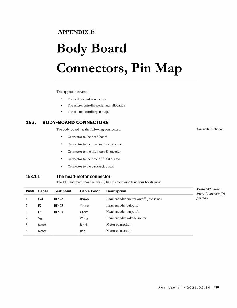
A N K I V E C T O R · 2 0 2 1 . 0 2 . 1 4 489
APPENDIX E
Body Board
Connectors, Pin Map
This appendix covers:
The body-board connectors
The microcontroller peripheral allocation
The microcontroller pin maps
153. BODY-BOARD CONNECTORS
The body-board has the following connectors:
Connector to the head-board
Connector to the head motor & encoder
Connector to the lift motor & encoder
Connector to the time of flight sensor
Connector to the backpack board
153.1.1 The head-motor connector
The P1 Head motor connector (P1) has the following functions for its pins:
Pin# Label Test point Cable Color Description
1 CAI HENCK Brown Head encoder emitter on/off (low is on)
2 E2 HENCB Yellow Head encoder output B
3 E1 HENCA Green Head encoder output A
4 VDD White Head encoder voltage source
5 Motor - Black Motor connection
6 Motor + Red Motor connection
Alexander Entinger
Table 607: Head
Motor Connector (P1)
pin map

A N K I V E C T O R · 2 0 2 1 . 0 2 . 1 4 490
153.1.2 The lift-motor connector
The lift motor connector (P2) has the following functions for its pins:
Pin# Label Test point Cable Color Description
1 CAI LENCK Brown Lift encoder emitter on/off (low is on)
2 E2 B Yellow Lift encoder output B
3 E1 A Green Lift encoder output A
4 VDD White Lift encoder voltage source
5 Motor - Black Motor connection
6 Motor + Red Motor connection
153.1.3 The time of flight connector
The front (Time of Flight) sensor connector has the following functions for its pins:
Pin# Label Test point Cable Color Description
1 VDD VDD (TP) Red Sensor voltage source
2 SCL1 Yellow I2C serial clock
3 SDA1 Green I2C serial data in/out
4 GND GND (DC) Black Sensor ground reference
153.1.4 Backpack connector
The flat-pack connector (P4) to the back-pack has the following functions for its pins:
Pin# Label Description
1 goes to Q17
2 has a 24M to head board power supply
3 MOSI has
4 MISO1
5 MISO2
6 VMAIN
7 PWR_B Power to the button
8 BAT_B Batter to the button
10 VDD Power for the microphones, LEDs, and logic
11
12
13 Touch
Table 608: Lift Motor
Connector (P2) pin
map
Table 609: Front
Sensor (time of flight)
Connector pin map
Table 610: Backpack
Connector pin map
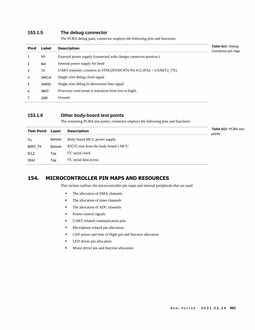
A N K I V E C T O R · 2 0 2 1 . 0 2 . 1 4 491
153.1.5 The debug connector
The PCBA debug pads, connector employs the following pins and functions:
Pin# Label Description
1 VX External power supply (connected with charger connector positive.)
2 BAI Internal power supply for head
3 TX UART transmit; connects to STM32F030C8T6 Pin #12 (PA2 = USART2_TX)
4 SWCLK Single wire debug clock signal
5 SWDIO Single wire debug bi-directional data signal
6 NRST Processor reset (reset is transition from low to high).
7 GND Ground
153.1.6 Other body-board test points
The remaining PCBA test points, connector employs the following pins and functions:
Test Point Layer Description
Vdd Bottom Body board MCU power supply
BODY_TX Bottom RS232 sent from the body board’s MCU
SCL2 Top I2C serial clock
SDA2 Top I2C serial data in/out
154. MICROCONTROLLER PIN MAPS AND RESOURCES
This section outlines the microcontroller pin maps and internal peripherals that are used.
The allocation of DMA channels
The allocation of timer channels
The allocation of ADC channels
Power control signals
UART-related communication pins
Microphone related pin allocation
Cliff sensor and time of flight pin and function allocation
LED driver pin allocation
Motor driver pin and function allocation
Table 611: Debug
Connector pin map
Table 612: PCBA test
points

A N K I V E C T O R · 2 0 2 1 . 0 2 . 1 4 492
The DMA channels are allocated for the following functions:
DMA Channel Function
1 Used to regularly sample all of the ADC channels
2 Used to received the data from the microphones on SPI1
3 Used by USART TX to send data, the microcontroller lists this as
USART1 RX, but it uses the receive signal to drive sending the data.
4 Used to received the data from the microphones on SPI2
5 Used to receive USART1 data from the head board
The internal hardware timers are allocated for the following functions:
Timer Function
1 Used to PWM the motors
3 Used to PWM the motors
6
14 used to drive internal events processing
15 The input (SPI clock) to divide the clock down for the microphones
16 The divided the SPI clock for the microphones
17 Probably used to clock out the stuff to the LCD
154.1.1 ADC inputs
The ADC module employs the following pins and functions:
Pin Function Test point Description
PA2 ADC Charger input. Note: this pin is shared with the charger USART
communication.
PA4 ADC VBat Battery measurement.
PA3 ADC Unknown.
PA6 ADC Touch sense.
154.1.2 Power control, management
The power control employs the following pins and functions:
Pin Function Test point Description
PA3 digital out Power to head board?
PA12 digital out Power enable to back pack? To R34 (100K) the to Q14, gate
PB9 digital out Power enable to the body board from the MP charger.
Note: see also the encoders section for their power control.
Table 613: DMA
channel usage
Table 614: Timer
usage
Table 615: UART
communication pin
map
Table 616: Power
control pin map

A N K I V E C T O R · 2 0 2 1 . 0 2 . 1 4 493
154.1.3 External Communication
The UART communication employs the following pins and functions:
Pin Function Test point Description
PA2 USART2 TX, RX
TX in/out USART to charger port 1-wire communication. The USART is put
into half-duplex operation, so it employs the same pin for RX and
RX. Note: this pin is shared with the charger ADC measurement.
PB6 USART1 TX BODY_TX out USART to the head board.
PB7 USART1 RX in USART from the head board
154.1.4 Microphone related pin map
The microphone interface employs the following pins and functions:
Pin Function Test point Description
PA5 SPI1 Clock out Clock from SPI1. May be fed into TIM15 CH2
PB4 SPI1 MISO in Data in from the microphones for SPI1
PB8 TIM16_CH1 The clock used to drive all of the microphones; derived from
scaling down an SPI clock.
PB13 SPI2 Clock out Clock from SPI2. May be fed into TIM15 CH2
PB14 SP12 MISO in Data in from the microphones for SPI2
PB15 TIM15 CH2 out The SPI clock probably goes into here for division
154.1.5 Proximity sensors: Cliff, and Time of flight
The cliff and time of flight proximity sensors employ the following pins and functions:
Pin Function Test point Description
PB10 I2C2 Clock out I2C clock to the peripherals. This is alternated with PF6 to access
different peripherals.
PB11 I2C2 Data in/out I2C data to/from the peripherals. This is alternated with PF7 to
access different peripherals.
PF6 I2C2 Clock SCL2 out I2C clock to the peripherals. This is alternated with PB10 to access
different peripherals.
PF7 I2C2 Data SDA2 in/out I2C data to/from the peripherals. This is alternated with PB11 to
access different peripherals.
Table 617: UART
communication pin
map
Table 618:
Microphone related
pin map
Table 619: Proximity
sensor pin map

A N K I V E C T O R · 2 0 2 1 . 0 2 . 1 4 494
154.1.6 LEDs
The LED controller employs the following pins:
Pin Function Test point Description
PA13 digital out The bits to be sent to the 74HC164. Note this pin also serves as
SWDIO.
PA14 digital out The clock for the bits sent to 74HC164. Note this pin also serves as
SWCLK.
154.1.7 Motor driver and encoders
The motor drivers use the following pins and functions:
Pin Function Test point Description
PA7 TIM1_CH1N out Motor 3 (Head), -, Q6,p1
PA8 TIM1_CH1 out Motor 3 (Head), +, Q2 p1
PA9 TIM1_CH2 out
PA10 TIM1_CH3 out Motor 0 (), +, Q1P1
PA11 TIM1_CH4 out Motor 2 (Lift), +, Q4p1,
PA15 digital out Motor 0 (), +, Q1P3. Note: configured as open drain output.
PB0 TIM1_CH2N out Motor 0 (), -, Q5P1
PB1 TIM3_CH4 out Motor 1 (), -, Q7P1
PB5 TIM3_CH2 out Motor 1 (), +, Q3P1
PB12 digital out Motor 3 (Head), +, Q2P3. Note: configured as open drain output.
PF0 digital out Motor 2 (Lift), +, Q4P3. Note: configured as open drain output.
PF1 digital out Motor 1 (), +, Q3P3. Note: configured as open drain output.
The motor encoders use the following pins and functions:
Pin Function Test point Description
PA0 digital HENCA in Head encoder output A
PA1 digital HENCB in Head encoder output B
PB2 digital A in Lift encoder output B
PB3 digital B in Lift encoder output A
PC13 digital out Power control for the encoders. Low is on, otherwise off
PC14 digital RTENC in Right motor encoder.
PC15 digital LTENC in Left tread encoder.
Table 620: Back-pack
LED logic pin map
Table 621: Motor
driver pin map
Table 622: Motor
encoder pin map

A N K I V E C T O R · 2 0 2 1 . 0 2 . 1 4 495
APPENDIX F
File system
This Appendix describes the file systems on Vector’s flash. As the Vector uses the Android boot-
loader, it reuses – or at least reserves – many of the Android partitions76 and file systems. Many
are probably not used. Quotes are from Android documentation.
The file system table tells us where they are stored in the partitions, and if they are non-volatile.
Mount point Partition name Description & Notes
/ BOOT_A The primary linux kernel and initramfs
/data77 USERDATA The data created for the specific robot (and user) that customizes it. A
factory reset wipes out this user data. This portion of the file system is
encrypted using “Linux Unified Key Setup” (LUKS).
/firmware MODEM The firmware for the WiFi/Bluetooth radio, and TrustZone modules
(trustlets). These modules are signed with the processor’s key.
/factory OEM Keys and configurations assigned to the individual robot at the factory,
and some logs.
/persist PERSIST Device specific “data which shouldn't be changed after the device is
shipped, e.g. DRM related files, sensor reg file (sns.reg) and calibration
data of chips; wifi, bluetooth, camera etc.”
/run Internal temporary file system; holding commands for the updating
setting, state of update processes, the fault codes, etc.
/media/ram /var/volatile /dev/sm
Internal temporary file systems; holds temporary files, interprocess
communication
The partition table78 found on the Vector:
Partition name Size Description & Notes
ABOOT 1 MB The primary and backup Android boot loader, which may load the kernel,
recovery, or fastboot. This is in the format of a signed, statically linked ELF
binary. ABOOTBAK 1 MB
BOOT_A 32 MB These are the primary and backup linux kernel and initramfs. Updates modify the
non-active partition, and then swap which one is active. BOOT_B 32 MB
CONFIG 512 KB This partition is not employed by Vector. It is zero’d out.
DDR 32 KB Configuration of the DDR RAM.
DEVINFO 1 MB This partition is not read by Vector. It is zero’d out.
In typical aboot implementations this partition is used to hold “device
information including: is_unlocked (aboot), is_tampered, is_verified,
charger_screen_enabled, display_panel, bootloader_version, radio_version etc.
76 https://forum.xda-developers.com/android/general/info-android-device-partitions-basic-t3586565 77 This is mounted by “mount-data.service” The file has a lot of information on how it unbricks 78 Much information from: https://source.android.com/devices/bootloader/partitions-images
Table 623: The file
system mount table
Table 624: The
partition table
adapted from Melanie
T

A N K I V E C T O R · 2 0 2 1 . 0 2 . 1 4 496
Contents of this partition are displayed by “fastboot oem device-info” command
in human readable format. Before loading boot.img or recovery.img, [the] boot
loader verifies the locked state from this partition.”
Vector’s aboot will write to this partition to indicate tampering when it finds that
the boot image does not pass integrity checks.
EMR 16 MB This is Vectors “Electronic Medical Record.” It holds Vector’s Model, Serial
Number, and such. It is a binary data structure, rather than a file system.
FSC 1KB “Modem FileSystem Cookies”
FSG 1.5 MB Golden backup copy of MODEMST1, used to restore it in the event of error
KEYSTORE 512 KB “Related to [USERDATA] Full Disk Encryption (FDE)”
MISC 1MB This is “a tiny partition used by recovery to communicate with boot-loader store
away some information about what it's doing in case the device is restarted while
the OTA package is being applied. It is a boot mode selector used to pass data
among various stages of the boot chain (boot into recovery mode, fastboot etc.).
e.g. if it is empty (all zero), system boots normally. If it contains recovery mode
selector, system boots into recovery mode.”
MODEM 64 MB Binary “blob” for the WiFi/Bluetooth radio firmware, and TrustZone trustlets.
These are signed by Anki, and the processor key.
MODEMST1 1.5MB A FAT file-system holding executables and binary “blobs” for the
WiFi/Bluetooth radio firmware, and TrustZone trustlets. These are signed by
Anki, and the processor key. Includes a lot of test code, probably for emissions
testing.
MODEMST2 1.5MB
OEM 16MB A modifiable ext2/4 file system that holds the logs, robot name, some calibration
info, and SDK TLS certificates.
PAD 1MB “related to OEM”
PERSIST 64MB This partition is not employed by Vector. It is zero’d out.
RECOVERY 32 MB An alternate partition holding kernel and initial RAM filesystem that allows the
system boot into a mode that can download a new system. Often used to wipe
out the updates.
RECOVERYFS 640 MB An alternate partition holding systems applications and libraries that let the
application boot into a mode that can download a new system. Often used to
wipe out the updates. This partition holds v0.90 of the Anki software.
RPM 512KB The primary and backup partitions for resource and power management. This is
in the format of a signed, statically linked ELF binary. RPMBAK 512KB
SBL1 512KB The primary and back up partitions for the secondary boot-loader. Responsible
for loading aboot; has an “Emergency” download (EDL) mode using
Qualcomm’s Sahara protocol. This is in the format of a signed, statically linked
ELF binary.
SBL1BAK 512KB
SEC 16KB The secure boot fuse settings, OEM settings, signed-boot-loader stuff
SSD 8KB “Secure software download” for secure storage, encrypted RSA keys, etc
SYSTEM_A 896MB The primary and backup system applications and libraries with application
specific code. Updates modify the non-active partition, and then swap which one
is active. SYSTEM_B 896MB
SWITCHBOARD 16 MB This is a modifiable data area used by Vic-switchboard to hold persistent
communication tokens. This appears to be a binary data structure, rather than a
file system.
TZ 768KB The primary and backup TrustZone. This is in the format of a signed, statically
linked ELF binary. This code is executed with special privileges to allow
encrypting and decrypting key-value pairs without any other modules (or
debuggers) having access to the secrets.
TZBAK 768KB

A N K I V E C T O R · 2 0 2 1 . 0 2 . 1 4 497
USERDATA 768MB The data created for the specific robot (and user) that customizes it. A factory
reset wipes out this user data. This partition is encrypted using “Linux Unified
Key Setup” (LUKS).
The following files are employed in the Vector binaries and scripts:
File Description
/anki/etc/revision Contains the robot revision number
/anki/etc/version Contains the robot version number
/data/data/com.anki.victor This folder is used to hold outgoing logging information and the
preferences.
/data/data/com.anki.victor/cache/crashDumps This folder is used to hold the minidump files produced when a
program crashes.
/data/data/com.anki.victor/cache/outgoing This folder is used to hold outgoing logs.
/data/data/com.anki.victor/cache/vic-logmgr A folder used to hold the log files while constructing the
compressed archive file that will be uploaded.
/data/diagnostics/ This folder is to holder outgoing logging information as it is
prepared to be sent over Bluetooth LE.
/data/etc/localtime The time zone
/data/etc/robot.pem The robot’s secret key that it used to generate the vic-gateway
public key. This file is created by mount-data.
/data/fault-reports This folder is used to hold the LTTng trace files and copy of the
log; an archive is made from these and placed into the outgoing
logs folder above.
/data/lib/connman/ The WiFi settings (managed by connman) are copied here.
/data/maintenance_reboot This is set when the system has rebooted for maintenance reasons
(e.g. updates)
/data/misc/bluetooth A folder to hold communication structures for the Bluetooth LE
stack.
/data/misc/bluetooth/abtd.socket The IPC socket interface to Anki’s Bluetooth LE service
/data/misc/bluetooth/btprop The IPC socket interface to BlueZ Bluetooth LE service.
/data/misc/camera
/data/panics
/data/data/com.anki.victor/persistent/switchboard /sessions
Used by Vic-switchboard to hold persistent session information,
e.g. tokens
/data/usb
/data/vic-gateway This folder holds the x509 certificate used by SDK & mobile app,
as well as a table of API tokens used to ensure that the SDK &
mobile app have been authenticated to use the bot.
/dev/block/bootdevice/by-name/emr File system access to the manufacturing records, including serial
number
/dev/block/bootdevice/by-name/switchboard File system access to switchboards persistent data.
/dev/rampost_error The status of the rampost checks of the body board.
/dev/socket/_anim_robot_server_ The IPC socket with Vector’s animation controller
/dev/socket/_engine_gateway_server_ The IPC socket interface to Vector’s Gateway [TBD] server
Table 625: Files
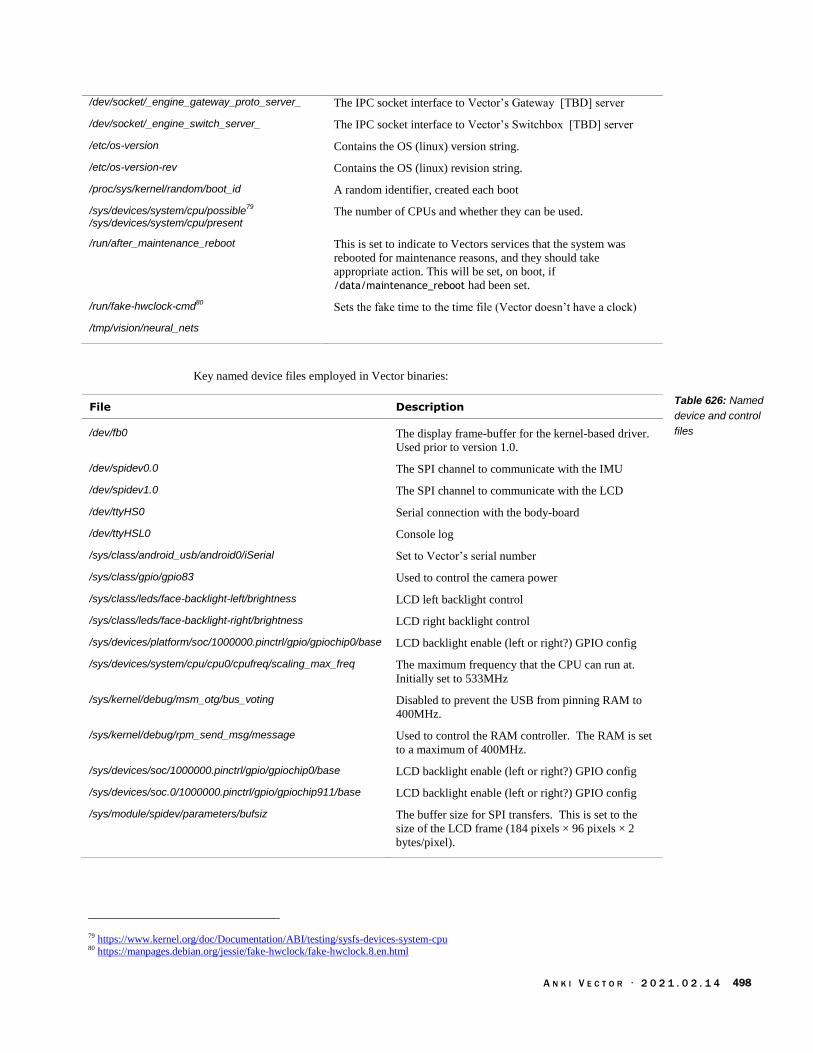
A N K I V E C T O R · 2 0 2 1 . 0 2 . 1 4 498
/dev/socket/_engine_gateway_proto_server_ The IPC socket interface to Vector’s Gateway [TBD] server
/dev/socket/_engine_switch_server_ The IPC socket interface to Vector’s Switchbox [TBD] server
/etc/os-version Contains the OS (linux) version string.
/etc/os-version-rev Contains the OS (linux) revision string.
/proc/sys/kernel/random/boot_id A random identifier, created each boot
/sys/devices/system/cpu/possible79
/sys/devices/system/cpu/present
The number of CPUs and whether they can be used.
/run/after_maintenance_reboot This is set to indicate to Vectors services that the system was
rebooted for maintenance reasons, and they should take
appropriate action. This will be set, on boot, if
/data/maintenance_reboot had been set.
/run/fake-hwclock-cmd80
Sets the fake time to the time file (Vector doesn’t have a clock)
/tmp/vision/neural_nets
Key named device files employed in Vector binaries:
File Description
/dev/fb0 The display frame-buffer for the kernel-based driver.
Used prior to version 1.0.
/dev/spidev0.0 The SPI channel to communicate with the IMU
/dev/spidev1.0 The SPI channel to communicate with the LCD
/dev/ttyHS0 Serial connection with the body-board
/dev/ttyHSL0 Console log
/sys/class/android_usb/android0/iSerial Set to Vector’s serial number
/sys/class/gpio/gpio83 Used to control the camera power
/sys/class/leds/face-backlight-left/brightness LCD left backlight control
/sys/class/leds/face-backlight-right/brightness LCD right backlight control
/sys/devices/platform/soc/1000000.pinctrl/gpio/gpiochip0/base LCD backlight enable (left or right?) GPIO config
/sys/devices/system/cpu/cpu0/cpufreq/scaling_max_freq The maximum frequency that the CPU can run at.
Initially set to 533MHz
/sys/kernel/debug/msm_otg/bus_voting Disabled to prevent the USB from pinning RAM to
400MHz.
/sys/kernel/debug/rpm_send_msg/message Used to control the RAM controller. The RAM is set
to a maximum of 400MHz.
/sys/devices/soc/1000000.pinctrl/gpio/gpiochip0/base LCD backlight enable (left or right?) GPIO config
/sys/devices/soc.0/1000000.pinctrl/gpio/gpiochip911/base LCD backlight enable (left or right?) GPIO config
/sys/module/spidev/parameters/bufsiz The buffer size for SPI transfers. This is set to the
size of the LCD frame (184 pixels × 96 pixels × 2
bytes/pixel).
79 https://www.kernel.org/doc/Documentation/ABI/testing/sysfs-devices-system-cpu 80 https://manpages.debian.org/jessie/fake-hwclock/fake-hwclock.8.en.html
Table 626: Named
device and control
files

A N K I V E C T O R · 2 0 2 1 . 0 2 . 1 4 499
APPENDIX G
Bluetooth LE Services
& Characteristics
This Appendix describes the configuration of the Bluetooth LE services – and the data access they
provide – for the accessory cube and for Vector.
155. CUBE SERVICES
The basic Bluetooth LE services:
Service UUID81 Description & Notes
Device Info Service82
180A16 Provides device and unit specific info –it’s
manufacturer, model number, hardware and
firmware versions
Generic Access Profile83
180016 The device name, and preferred connection
parameters.
Generic Attribute Transport84
180116 Provides access to the services.
Cube’s Service C6F6C70F-D219-598B-FB4C-
308E1F22F83016 Service custom to the cube, reporting battery,
accelerometer and date of manufacture
Note: It appears that there isn’t a battery service on the Cube. When in over-the-air update mode,
there may be other services present (i.e. by a boot-loader)
Element Value
Device Name (Default) “Vector Cube”
Firmware Revision “v_5.0.4”
Manufacturer Name "Anki"
Model Number "Production"
Software Revision “2.0.0”
81 All values are a little endian, per the Bluetooth 4.0 GATT specification 82 http://developer.bluetooth.org/gatt/services/Pages/ServiceViewer.aspx?u=org.bluetooth.service.device_information.xml 83 http://developer.bluetooth.org/gatt/services/Pages/ServiceViewer.aspx?u=org.bluetooth.service.generic_access.xml 84 http://developer.bluetooth.org/gatt/services/Pages/ServiceViewer.aspx?u=org.bluetooth.service.generic_attribute.xml
Table 627: The
Bluetooth LE services
Table 628: The
Cube’s Device info
settings

A N K I V E C T O R · 2 0 2 1 . 0 2 . 1 4 500
155.1. CUBE’S SERVICES
Values are little-endian, except where otherwise stated.
UUID Access Description & Notes
0EA75290-6759-A58D-7948-598C4E02D94A16 Write Sets the LED patterns
450AA175-8D85-16A6-9148-D50E2EB7B79E16 Read The version string of the application firmware.
This is also the date and time of the firmware
build.
43EF14AF-5FB1-7B81-3647-2A9477824CAB16 Read, Notify, Indicate
Reads the battery and accelerometer.
Subscribing to this will stream the
accelerometer data.
9590BA9C-5140-92B5-1844-5F9D681557A416 Write OTA update. This is used to send the
application firmware to the Cube.
See chapter 14 for a description of the commands that go over this service.
156. VECTOR SERVICES
Times and other feature parameters:
Service UUID85 Description & Notes
Generic Access Profile 180016 The device name, and preferred connection
parameters
Generic Attribute Transport 180116 Provides access to the services.
Vector’s Serial Service FEE316 The service with which we can talk to Vector.
It appears that there isn’t a battery service on the Vector.
Element Value
Device Name (Default) “Vector” followed by his serial number
156.1. VECTOR’S SERIAL SERVICE
UUID Access Format Notes
30619F2D-0F54-41BD-A65A-7588D8C85B4516
Read, Notify,Indicate
7D2A4BDA-D29B-4152-B725-2491478C5CD716
write
See chapter 13 for a description of the commands that go over this service.
85 All values are a little endian, per the Bluetooth 4.0 GATT specification
Table 629: Cube’s
accelerometer service
characteristics
Table 630: Vector’s
Bluetooth LE services
Table 631: The
Vector’s Device info
settings
Table 632: Vector’s
serial service
characteristics

A N K I V E C T O R · 2 0 2 1 . 0 2 . 1 4 501
APPENDIX H
Servers & Data
Schema
This Appendix describes the servers that Vector contacts86
Server Description & Notes
chipper.api.anki.com:443 The speech recognition engine is contacted thru
this server.
chipper-dev.api.anki.com:443 Development Vectors contact this speech
recognition engine server.
conncheck.global.anki-services.com/ok This server is used to check to see if Vector can
connect to Anki.
conncheck.global.anki-dev-services.com/ok This server is used to check to see if development
Vectors can connect to Anki.
jdocs.api.anki.com:443 Server used to store of some of preferences, usage
stats.
jdocs-dev.api.anki.com:443 Server used by development Vectors to store of
some of preferences, usage stats.
s3://anki-device-logs-dev/victor Development Vectors send their log files here.
token.api.anki.com:443 This server is used to provide the API certificate.87
token-dev.api.anki.com:443 This server is used to provide the API certificate
for development Vectors.
https://anki.sp.backtrace.io:6098/post?format=minidump&token=6fd2bd053e8dd542ee97c05903b1ea068f090d37c7f6bbfa873c5f3b9c40b1d9
Vector posts crashes (linux minidumps) to this
server. This is hard coded in anki-crashuploader
https://sqs.us-west-2.amazonaws.com/792379844846/DasProd-dasprodSqs-1845FTIME3RHN
This is used to synchronize with data analytics
services.
https://ota.global.anki-services.com/vic/prod/ Server used to check for updates
https://ota.global.anki-dev-services.com/vic/rc/lo8awreh23498sf/
For the Developer branch
amazon.com/code
86 Todo: sync up with info at: https://github.com/anki-community/vector-archive 87 Project Victor had a write up, reference that.
Table 633: The
servers that Vector
contacts.

A N K I V E C T O R · 2 0 2 1 . 0 2 . 1 4 502
The mobile application contacts the following servers:
Server Description & Notes
https://locations.api.anki.com/1/locations This is used to provide a list of locations to the
mobile application that the Chipper servers will
recognize. Without this, you cannot change
Vector’s location in the mobile application
The Alexa modules contact the following servers:
Server Description & Notes
https://api.amazon.com/auth/O2/ Used to authenticate the account for the Alexa
device.
https://avs-alexa-na.amazon.com The Alexa Voice Service that accepts the spoken
audio and returns a rich intent. Amazon changed
preferred URLs on 2019 May 22, and this is
considered legacy.88
88 https://developer.amazon.com/docs/alexa-voice-service/api-overview.html
Table 634: The
servers that the mobile
application contacts.
Table 635: The
Amazon Alexa Voice
Service servers that
Vector contacts.

A N K I V E C T O R · 2 0 2 1 . 0 2 . 1 4 503
APPENDIX I
Features
The following is the set of application-level feature flags and whether they are enabled (i.e.
sufficiently developed to be used) in Vector:
Feature enabled Description & Notes
ActiveIntentFeedback true
Alexa true The ability to use Alexa
Alexa_AU true The ability to use Alexa, localized for Australia
Alexa_UK true The ability to use Alexa, localized for the UK
AttentionTransfer false
CubeSpinner false
Dancing true The ability for Vector to dance to music.
Exploring true The ability for Vector to explore his area
EyeColorVC true The ability to set Vector’s eye color through a voice command
FetchCube true The ability for Vector to fetch his cube
FindCube true The ability for Vector to find his cube
GazeDirection false
GreetAfterLongTime true
HandDetection true The ability for Vector to spot hands
HeldInPalm true
HowOldAreYou true The ability for Vector to track how long it has been since he was
activated (his age) and use that info to respond to the question “How
old are you?”
Invalid false
Keepaway true
KnowledgeGraph true The ability for Vector to answer a question when asked “Hey Vector,
I have a question…”
Laser false
Messaging false
MoveCube true
PopAWheelie true The ability for Vector pop a wheelie using his cube
PRDemo false
ReactToHeldCube true
ReactToIllumination true
RollCube true The ability for Vector to drive up and roll his cube
Table 636: The
features

A N K I V E C T O R · 2 0 2 1 . 0 2 . 1 4 504
StayOnChargerUntilCharged true
TestFeature false
Volume true The ability to set Vector’s volume by voice command.
The following is the set of AI features (related to, but the same as the feature flags), which identify
an active behavior:
Feature Description & Notes
Alexa This behavior is used to perform Alexa-based interaction.
AskForHelp ? Is Vector asking for help?
BasicVoiceCommand Vector is responding to a wake word and intent.
BeQuiet Vector is responding to the intent TBD to be quiet (make no sounds
and not move).
Blackjack Vector is playing a game of Blackjack.
CantDoThat
ComeHere Vector is going to the speaker.
CubeSpinner
DanceToTheBeat Vector is dancing to music.
Exploring Vector is driving and exploring his area.
FetchCube Vector is fetching his cube.
FindCube Vector is looking for his cube. This is done prior to fetching a cube,
if Vector doesn’t know where it is.
FindHome Vector is looking for his home (the charger). This is done if Vector
needs to charger, and doesn’t know where the charger is.
FistBump If Vector has received a fist bump. Note this can be a result of the
shaking of lifting the cube, driving with the cube, or putting it down.
Frustrated Vector is frustrated and throwing a little tantrum.
GoHome Vector is driving home to his charger, often in response to a low
battery.
HeldInPalm Vector is held in the palm of a hand; he may coo or throw a little
tantrum.
HowOldAreYou Vector has been asked how long it has been since he was activated
(his age) and telling his human.
InteractWithFaces
InTheAir Vector has detected that his in the air. If he thinks he is falling, he
may engage in “tuck and roll” where lowers his lift, and tilts his head
down.
KeepAway
KnowledgeGraph Vector has been ask to answer a question (“Hey Vector, I have a
question…”) and this behaviour is used to perform the rest of the
interaction.
ListeningForBeats Vector thinks that music may be playing and is listening for the beat
of the music to dance to. (He may follow this with the
DanceToTheBeat feature).
LookAtMe Vector is looking for a person face, to look into their gaze.
Table 637: The AI
behaviour features

A N K I V E C T O R · 2 0 2 1 . 0 2 . 1 4 505
LowBattery Vector’s battery level is low and he needs to begin looking for the
charger.
MeetVictor Vector is performing the on-boarding steps.
MoveCube
MovementBackward
MovementForward
MovementLeft
MovementRight
MovementTurnAround
NoFeature When Vector’s mind isn’t doing anything and his mind is blank…
he’ll probably pick exploring, observing, or sleeping as his next
activity.
Observing Vector is looking around.
ObservingOnCharger Vector is looking around while on his charger.
Petting Vector is being petting.
PlayingMessage The messaging features are not yet support.
PopAWheelie Vector is attempting to pop a wheelie using his cube.
ReactToAbuse Vector is responding to verbally abusive statements (represented as
an intent).
ReactToAffirmative Vector is responding to verbal complements (represented as an
intent).
ReactToApology Vector is responding to an apology (represented as an intent).
ReactToCliff Vector has detected a cliff while driving, and is reacting to it.
ReactToGazeDirection Vector has detected a face looking at him (the gaze) and is reacting
to it.
ReactToGoodBye Vector is responding to a verbal goodbye (represented as an intent).
ReactToGoodMorning Vector is responding to a verbal good morning (represented as an
intent).
ReactToHand Vector has seen a hand and is reacting to it.
ReactToHello Vector is responding to a verbal hello (represented as an intent).
ReactToLove Vector is responding to a verbal statement of affection (represented
as an intent).
ReactToNegative Vector is responding to verbal abuse.
ReactToRobotOnSide Vector has fallen (possibly from driving off the edge of his area) and
is on his side.
RecordingMessage The messaging features are not yet support.
RequestCharger Vector is asking his human to help him by putting him on his
charger. This happens if Vector can’t get to his charger – he is stuck
or doesn’t know where it is.
RobotShaken Vector has detected being shaken, like a snow globe
RollBlock The ability for Vector to drive up and roll his cube
SDK
SeasonalHappyHoliday Vector is animating a little celebration video suitable for Christmas
and other holidays.

A N K I V E C T O R · 2 0 2 1 . 0 2 . 1 4 506
SeasonalHappyNewYear Vector is animating a little celebration video suitable for New Years.
ShutUp
Sleeping Vector is sleeping, usually on his charging, and waiting for
stimulation.
StuckOnEdge Vector has driven at least one of
TakeAPhoto Vector is taking a photo.
TimerCanceled Vector is cancelling the timer, as part of the timer behavior
TimerChecked Vector is answering “how long is left on the timer”, as part of the
timer behavior.
TimerReminder
TimerRinging Vector is playing the timer ring (i.e. the timer has expired) animation
as part of the timer behavior.
TimerSet
UnmatchedVoiceIntent The cloud wasn’t able to identify an intent based on what was said (if
anything) after the Hey Vector wake word.
VolumeAdjustment Vector’s volume was adjusted by a voice command.
Weather Vector is looking up the weather (from the cloud) and animating the
results.
WhatsMyName Vector is looking for a face and identifying it.

A N K I V E C T O R · 2 0 2 1 . 0 2 . 1 4 507
APPENDIX J
Phrases and their
Intent
This Appendix maps the published phrases that Vector responds to and their intent:
Intent Enumeration Phrase
movement_backward 23 Back up
imperative_scold 18 Bad robot
imperative_quiet Be quiet
global_stop 3 Cancel the timer
Change/set your eye color to [blue, green, lime, orange, purple,
sapphire, teal, yellow].
check_timer 1 Check the timer
imperative_come 10 Come here
imperative_dance 11 Dance.
play_popawheelie 34 Do a wheelstand
imperative_fetchcube 12 Fetch your cube
imperative_findcube 13 Find your cube
play_fistbump 32 Fist Bump
play_fistbump 32 Give me a Fist Bump
movement_backward 23 Go backward
explore_start 2 Go explore
movement_forward 22 Go forward.
movement_turnleft 24 Go left
movement_turnright 25 Go right
system_sleep Go to sleep
system_charger Go to your charger
Good afternoon
greeting_goodbye 4 Goodbye
Good evening
greeting_goodnight Good night
greeting_goodmorning 5 Good morning
imperative_praise 16 Good robot
Table 638: The “Hey
Vector” phrases

A N K I V E C T O R · 2 0 2 1 . 0 2 . 1 4 508
seasonal_happyholidays 36 Happy Holidays
seasonal_happynewyear 37 Happy New Year
greeting_hello 6 Hello
He’s behind you
character_age 0 How old are you
imperative_abuse 7 I hate you.
knowledge_question 27 I have a question …
imperative_love 15 I love you.
imperative_apology 9 I’m sorry.
play_blackjack 31 Let’s play Blackjack
Listen to music
imperative_lookatme 14 Look at me
Look behind you
My name is [Your Name]
imperative_negative 17 No
play_pickupcube 33 Pick up your cube.
play_anygame 29 Play a game
play_anytrick 30 Play a trick
play_blackjack 31 Play Blackjack
play_popawheelie 34 Pop a wheelie.
play_rollcube 35 Roll your Cube
imperative_quiet Quiet down
Run
set_timer 38 Set a timer for [length of time]
imperative_shutup Shut up
explore_start 2 Start Exploring
Stop Exploring
global_stop 3 Stop the timer
take_a_photo 40 Take a picture of [me/us]
take_a_photo 40 Take a picture
take_a_photo 40 Take a selfie
movement_turnaround 26 Turn around
movement_turnleft 24 Turn left
{same as be quiet } Turn off
movement_turnright 25 Turn right
imperative_volumelevel 19 Volume [number].
imperative_volumedown 21 Volume down
imperative_volumeup 20 Volume up.
Volume maximum
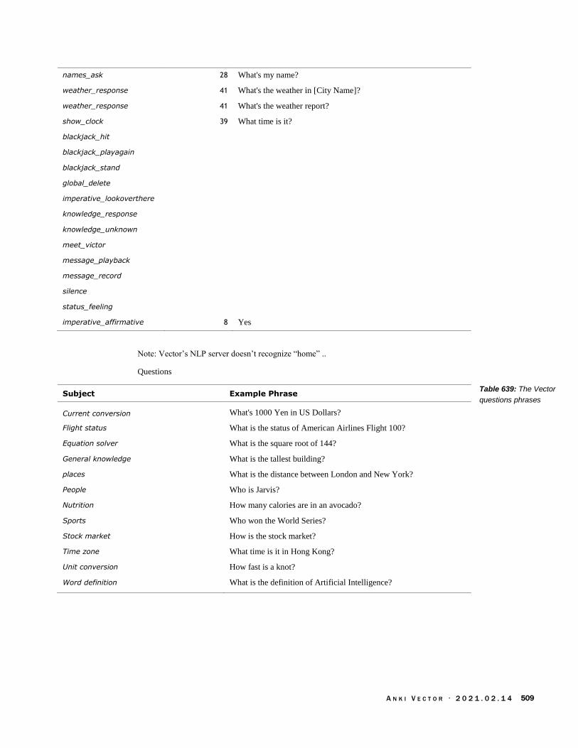
A N K I V E C T O R · 2 0 2 1 . 0 2 . 1 4 509
names_ask 28 What's my name?
weather_response 41 What's the weather in [City Name]?
weather_response 41 What's the weather report?
show_clock 39 What time is it?
blackjack_hit
blackjack_playagain
blackjack_stand
global_delete
imperative_lookoverthere
knowledge_response
knowledge_unknown
meet_victor
message_playback
message_record
silence
status_feeling
imperative_affirmative 8 Yes
Note: Vector’s NLP server doesn’t recognize “home” ..
Questions
Subject Example Phrase
Current conversion What's 1000 Yen in US Dollars?
Flight status What is the status of American Airlines Flight 100?
Equation solver What is the square root of 144?
General knowledge What is the tallest building?
places What is the distance between London and New York?
People Who is Jarvis?
Nutrition How many calories are in an avocado?
Sports Who won the World Series?
Stock market How is the stock market?
Time zone What time is it in Hong Kong?
Unit conversion How fast is a knot?
Word definition What is the definition of Artificial Intelligence?
Table 639: The Vector
questions phrases

A N K I V E C T O R · 2 0 2 1 . 0 2 . 1 4 510
User Intent Cloud Intent App Intent Feature Flag
amazon_signin intent_amazon_signin
amazon_signout intent_amazon_signout
blackjack_hit intent_blackjack_hit
blackjack_playagain intent_blackjack_playagain
blackjack_stand intent_blackjack_stand
character_age intent_character_age HowOldAreYou
check_timer intent_clock_checktimer
explore_start intent_explore_start explore_start Exploring
global_delete intent_global_delete_extend
global_stop intent_global_stop_extend
greeting_goodbye intent_greeting_goodbye
greeting_hello intent_greeting_hello
greeting_goodmorning intent_greeting_goodmorning
greeting_goodnight intent_greeting_goodnight
imperative_abuse intent_imperative_abuse
imperative_affirmative intent_imperative_affirmative
imperative_apology intent_imperative_apologize
imperative_come intent_imperative_come intent_imperative_come
imperative_dance intent_imperative_dance intent_imperative_dance
imperative_eyecolor intent_imperative_eyecolor EyeColorVC
imperative_eyecolor_specific
intent_imperative_eyecolor_specific_extend
EyeColorVC
imperative_fetchcube intent_imperative_fetchcube intent_imperative_fetchcube FetchCube
imperative_findcube intent_imperative_findcube intent_imperative_findcube FindCube
imperative_lookatme intent_imperative_lookatme intent_imperative_lookatme
imperative_lookoverthere intent_imperative_lookoverthere intent_imperative_lookoverthere GazeDirection
imperative_love intent_imperative_love
imperative_negative intent_imperative_negative
imperative_praise intent_imperative_praise
imperative_scold intent_imperative_scold
imperative_quiet intent_imperative_quiet intent_imperative_quiet
imperative_shutup intent_imperative_shutup intent_imperative_shutup
imperative_volumedown intent_imperative_volumedown Volume
imperative_volumelevel intent_imperative_volumelevel_extend Volume
imperative_volumeup intent_imperative_volumeup Volume
knowledge_question intent_knowledge_promptquestion knowledge_question KnowledgeGraph
knowledge_response intent_knowledge_response_extend knowledge_response KnowledgeGraph
knowledge_unknown intent_knowledge_no_response knowledge_unknown KnowledgeGraph
meet_victor intent_names_username_extend intent_meet_victor
message_playback intent_message_playmessage_extend intent_message_playmessage Messaging
message_record intent_message_recordmessage_extend intent_message_recordmessage Messaging
movement_backward intent_imperative_backup
Table 640: Mapping of
different intent names

A N K I V E C T O R · 2 0 2 1 . 0 2 . 1 4 511
movement_forward intent_imperative_forward
movement_turnaround intent_imperative_turnaround
movement_turnleft intent_imperative_turnleft
movement_turnright intent_imperative_turnright
names_ask intent_names_ask intent_names_ask
play_anygame intent_play_anygame
play_anytrick intent_play_anytrick
play_blackjack intent_play_blackjack
play_fistbump intent_play_fistbump
play_pickupcube intent_play_pickupcube
play_popawheelie intent_play_popawheelie
play_rollcube intent_play_rollcube
play_specific intent_play_specific_extend intent_play_specific
seasonal_happyholidays intent_seasonal_happyholidays
seasonal_happynewyear intent_seasonal_happynewyear
set_timer intent_clock_settimer_extend intent_clock_settimer
show_clock intent_clock_time
silence intent_system_noaudio
status_feeling intent_status_feeling
system_charger intent_system_charger intent_system_charger
system_sleep intent_system_sleep intent_system_sleep
take_a_photo intent_photo_take_extend
unmatched_intent
weather_response intent_weather_extend

A N K I V E C T O R · 2 0 2 1 . 0 2 . 1 4 512
APPENDIX K
Emotion Events
The following is the set of emotion names used by Vector’s mood manager. Some are from
external events. Many whether or not a behavior or action succeeded, or failed (failed with retry,
failed with abort).
Emotion Name Description and notes
Ambient light ReactToDark
Charger DriveOffCharger Vector was able to drive off of the charger.
MountChargerSuccess Vector was able to drive onto of the charger
successfully.
PlacedOnCharger Vector was place on the charger.
Cube CubeSpinner
KeepawayPounce
KeepawayStarted
PickingOrPlacingActionFailedWithAbort Vector was unable to pick up his cube or to place it
successfully, and the action was aborted.
PickingOrPlacingActionFailedWithRetry Vector was unable to pick up his cube or to place it
successfully, even with retries.
PickupSucceeded Vector picked up his cube successfully.
RollSucceeded Vector rolled his cube successfully.
Driving CliffReact Vector encountered a cliff and reacted.
DrivingActionFailedWithAbort Vector was unable to drive to his target successfully,
and the action was aborted.
DrivingActionFailedWithRetry Vector was unable to drive to his target successfully,
even with retries.
DrivingActionSucceeded Vector was able to drive to his target successfully.
ExploringExamineObstacle Vector found an obstacle (possibly a marked object)
to look at while exploring.
FoundObservedObject Vector found an object he knows about.
ReactToObstacle Vector is reacting to the obstacle he encountered
while driving,
Faces DrivingToFace Vector is driving to a face.
DriveToFaceSuccess Vector was able to drive to a face successfully.
EnrolledNewFace Vector associated a new face with a name.
EyeContactReaction Vector detected the gaze of someone looking at him.
GreetingSayName Vector said the name of someone he recognized.
InteractWithFaceRetry
Table 641: The
emotion event names

A N K I V E C T O R · 2 0 2 1 . 0 2 . 1 4 513
InteractWithNamedFace Vector is looking at the face of someone he knows.
InteractWithUnnamedFace Vector is looking at the face of someone he doesn’t
know.
LookAtFaceVerified
Intents BeQuietVoiceCommand Vector was told to be quiet.
FistBumpLeftHanging Vector attempted a fist bump, but no one gave him
one.
FistBumpSuccess Vector received a fist bump.
NoValidVoiceIntent The wake word was sent, but an intent was either
unable to be identified, or the returned intent is not
recognized.
OnboardingStarted Vector has started the process of on boarding his
human companion.
ReactToTriggerWord The wake word was said, and Vector has reacted to
it.
RespondToGoodNight Vector responded to a verbal goodnight (represented
as an intent)
RespondToShortVoiceCommand Vector responded to an intent that didn’t trigger a
more complex behavior interaction.
Motion sensing ReactToMotion
ReactToPickedUp Vector has been picked up and has reacted to it.
ReactToUnexpectedMovement
RobotShaken Vector was shaken.
Power State Asleep Vector is asleep
Sleeping Vector is sleeping
Petting PettingBlissLevelIncrease Vector is being petted.
PettingReachedMaxBliss Vector is being petted.
PettingStarted Vector is being petted.
Sound DanceToTheBeat Vector is dancing to music that he hears (he may be
the only one to hear it)
ReactToSoundAsleep Vector heard some noise while asleep or sleeping.
ReactToSoundAwake Vector heard some noise (but wasn’t asleep)
Timer TimerRinging Vector’s timer has expired and is ringing.

A N K I V E C T O R · 2 0 2 1 . 0 2 . 1 4 514
APPENDIX L
DAS Tracked Events
and Statistics
This Appendix captures the events and statistics that are posted to Anki’s the diagnostics /
analytics services (see Chapter 33)
157. DAS TRACKED EVENTS AND STATISTICS
157.1. BASIC INFORMATION
157.1.1 Version Information
The following are version-information related events that are posted to the diagnostic logger:
Event Description & Notes
hal.body_version
robot.boot_info
robot.cpu_info
robot.disk_info
robot.memory_info
157.1.2 Crashes, Faults and other error information
The following are crash, fault and other error related entries:
Event Description & Notes
dasmgr.upload.failed The DAS manager was unable to contact or
successfully upload the DAS events.
log.error There was an error with the logging system,
including errors with DAS manager uploads.
robot.crash The robot software crashed
robot.fault_code The robot fault code explaining which processes
exited or task failed; the same as the one displayed.
robot.imu_failure There was a problem communicating with or
calibrating the IMU
vectorbot.main_cycle_too_late
vectorbot.main_cycle_too_long
Table 642: Version
info, posted to DAS
Table 643: Crash,
fault and error related
DAS events

A N K I V E C T O R · 2 0 2 1 . 0 2 . 1 4 515
Note: see the IMU section for events related to IMU
157.1.3 Start-up Information not described elsewhere
The following are start-up events that are posted to the diagnostic logger:
Event Description & Notes
das.allow_upload
ntp.timesync
profile_id.start
profile_id.stop
rampost.lcd_check
random_generator.seed The random number generator was initialized.
robot.engine_ready
robot.init.time_spent_ms
robot.maintenance_reboot Whether or not a maintenance reboot was able to be
performed and, if not, why; or indicates that it is
proceeding.
switchboard.hello
vic.cloud.hello.world
Note: other startup events are covered elsewhere with their functional groups.
157.2. POWER MANAGEMENT EVENTS AND STATISTICS
The power management posts the following set of related events:
Event Description & Notes
behavior.sleeping.falling_asleep
behavior.sleeping.wake_up
engine.power_save.end
engine.power_save.start
hal.active_power_mode
robot.power_off
robot.power_on
vectorbot.prep_for_shutdown
Table 644: Start up
information, posted to
DAS
Table 645: Power
management events,
posted to DAS
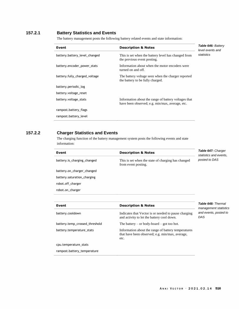
A N K I V E C T O R · 2 0 2 1 . 0 2 . 1 4 516
157.2.1 Battery Statistics and Events
The battery management posts the following battery related events and state information:
Event Description & Notes
battery.battery_level_changed This is set when the battery level has changed from
the previous event posting.
battery.encoder_power_stats Information about when the motor encoders were
turned on and off.
battery.fully_charged_voltage The battery voltage seen when the charger reported
the battery to be fully charged.
battery.periodic_log
battery.voltage_reset
battery.voltage_stats Information about the range of battery voltages that
have been observed; e.g. min/max, average, etc.
rampost.battery_flags
rampost.battery_level
157.2.2 Charger Statistics and Events
The charging function of the battery management system posts the following events and state
information:
Event Description & Notes
battery.is_charging_changed This is set when the state of charging has changed
from event posting.
battery.on_charger_changed
battery.saturation_charging
robot.off_charger
robot.on_charger
Event Description & Notes
battery.cooldown Indicates that Vector is or needed to pause charging
and activity to let the battery cool down.
battery.temp_crossed_threshold The battery – or body-board – got too hot.
battery.temperature_stats Information about the range of battery temperatures
that have been observed; e.g. min/max, average,
etc.
cpu.temperature_stats
rampost.battery_temperature
Table 646: Battery
level events and
statistics
Table 647: Charger
statistics and events,
posted to DAS
Table 648: Thermal
management statistics
and events, posted to
DAS

A N K I V E C T O R · 2 0 2 1 . 0 2 . 1 4 517
157.3. SENSOR STATISTICS AND EVENTS
157.3.1 IMU Events
The IMU and navigation subsystem posts the following events and statistics:
Event Description & Notes
gyro.bias_detected
gyro.drift_detected
imu_filter.fall_impact_event
imu_filter.falling_event
imu_filter.gyro_calibrated
157.3.2 Microphone & Sound Events
The system posts the following events and state information related to Vector’s microphones:
Event Description & Notes
behavior.trigger_word.dropped
behavior.voice_command.dropped
mic_data_system.speech_trigger_recognized
robot.microphone_on
robot.reacted_to_sound
robot. stuck_mic_bit
wakeword.triggered
wakeword.vad
157.3.3 Proximity Sensor Statistics and Events
The system posts the following events and state information related to Vector’s proximity sensors:
Event Description & Notes
hal.invalid_prox_reading_report
hal.severe_invalid_prox_reading_report
robot.cliff_detected
robot.bad_prox_data
157.3.4 Touch Sensor Statistics and Events
The system posts the following touch-related events and state information:
Event Description & Notes
touch_sensor.activate_charger_mode_check
Table 649: IMU,
navigation events
Table 650:
Microphone statistics
and events, posted to
DAS
Table 651: Proximity
sensor statistics and
events, posted to DAS
Table 652: Touch
sensor statistics and
events, posted to DAS

A N K I V E C T O R · 2 0 2 1 . 0 2 . 1 4 518
touch_sensor.baseline_fast_calibration_finished
touch_sensor.baseline_reading_difference_monitor_too_low
touch_sensor.charger_mode_check.baseline_changed
touch_sensor.charger_mode_check.no_baseline_change
157.4. MOTOR STATISTICS AND EVENTS
The motor controllers post the following events and statistics:
Event Description & Notes
calibrate_motors
head_motor_calibrated
head_motor_uncalibrated
lift_motor_calibrated
lift_motor_uncalibrated
157.5. COMMUNICATION RELATED EVENTS POSTED TO DAS
157.5.1 Body-Board / Spine Related Events Posted to DAS
The communication with the body-board controller posts the following events:
Event Description & Notes
rampost.dfu.desired_version
rampost.dfu.open_file
rampost.dfu.installed_version
rampost.dfu.request_version
rampost.rampost.exit The rampost has completed and exited.
rampost.spine.configure_serial_port The rampost program was successful in configuring
the serial port to communicate with the body-board.
rampost.spine.open_serial The rampost was able to open the serial port to
communicate with the body-board.
rampost.spine.select_timeout There was a timeout in communicating with
rampost the body-board.
Note: see the updates section for events related to updating the body-board firmware
Table 653: Motor
events
Table 654: Body-
board / spine related
DAS events

A N K I V E C T O R · 2 0 2 1 . 0 2 . 1 4 519
157.5.2 Bluetooth LE / WiFi Related Events Posted to DAS
The wireless communication posts the following events:
Event Description & Notes
ble.connection
ble_conn_id.start
ble_conn_id.stop
ble.disconnection
dasmgr.upload.stats
dasmgr.upload.failed
robot.cloud_response_failed
robot.wifi_info
robot.sdk_wrong_version
wifi_conn_id.start
wifi_conn_id.stop
wifi.connection
wifi.disconnection
wifi.initial_state
157.5.3 Accessory-Related Events Posted to DAS
The communication with the mobile application and SDK posts the following events:
Event Description & Notes
cube.battery_voltage The cube’s battery voltage
cube.connected Vector was able to connect to his accessory
companion cube.
cube.connection_failed Vector was unable to connect to his accessory
companion cube.
cube_connection_coordinator.connection_requested
cube_connection_coordinator.disconnect_requested
cube_connection_coordinator.unexpected_disconnect
cube.disconnected Vector lost the connection with his accessory
companion cube.
cube.firmware_mismatch Vector is unable to use his accessory companion
cube as is, since the firmware version is not
compatible.
cube.low_battery
cube.scan_result
cube.unexpected_connect_disconnect
Note: see the updates section for events related to updating the cube firmware
Table 655: Bluetooth
LE, WiFi related DAS
events
Table 656: Accessory
cube related DAS
events

A N K I V E C T O R · 2 0 2 1 . 0 2 . 1 4 520
157.6. SETTINGS AND PREFERENCES EVENTS
The following are settings and preference related events that are posted to the diagnostic logger:
Event Description & Notes
das.allow_upload Whether or not the account owner – Vector’s
human – has opted in (true) or opted out (false) of
data gathering, allowing the DAS events to be
uploaded to the servers.
dasmgr.upload.stats
engine.language_locale The IETF language tag of the human companion’s
language preference – American English, UK
English, Australian English, German, French,
Japanese, etc.
default: “en-US”
robot.cleared_user_data
robot.locale The IETF language tag of the human companion’s
language preference – American English, UK
English, Australian English, German, French,
Japanese, etc.
default: “en-US”
robot.settings.passed_to_cloud_jdoc
robot.settings.updated
robot.settings.volume
robot.timezone The “tz database name” for time zone to use for the
time and alarms.
default: “America/Los_Angeles”
sdk.activate
Table 657: Settings
and preferences
events posted to DAS
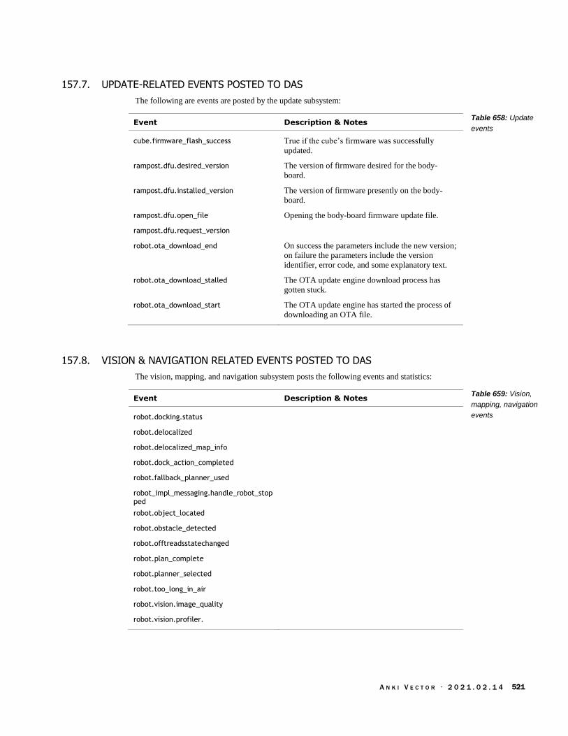
A N K I V E C T O R · 2 0 2 1 . 0 2 . 1 4 521
157.7. UPDATE-RELATED EVENTS POSTED TO DAS
The following are events are posted by the update subsystem:
Event Description & Notes
cube.firmware_flash_success True if the cube’s firmware was successfully
updated.
rampost.dfu.desired_version The version of firmware desired for the body-
board.
rampost.dfu.installed_version The version of firmware presently on the body-
board.
rampost.dfu.open_file Opening the body-board firmware update file.
rampost.dfu.request_version
robot.ota_download_end On success the parameters include the new version;
on failure the parameters include the version
identifier, error code, and some explanatory text.
robot.ota_download_stalled The OTA update engine download process has
gotten stuck.
robot.ota_download_start The OTA update engine has started the process of
downloading an OTA file.
157.8. VISION & NAVIGATION RELATED EVENTS POSTED TO DAS
The vision, mapping, and navigation subsystem posts the following events and statistics:
Event Description & Notes
robot.docking.status
robot.delocalized
robot.delocalized_map_info
robot.dock_action_completed
robot.fallback_planner_used
robot_impl_messaging.handle_robot_stopped
robot.object_located
robot.obstacle_detected
robot.offtreadsstatechanged
robot.plan_complete
robot.planner_selected
robot.too_long_in_air
robot.vision.image_quality
robot.vision.profiler.
Table 658: Update
events
Table 659: Vision,
mapping, navigation
events
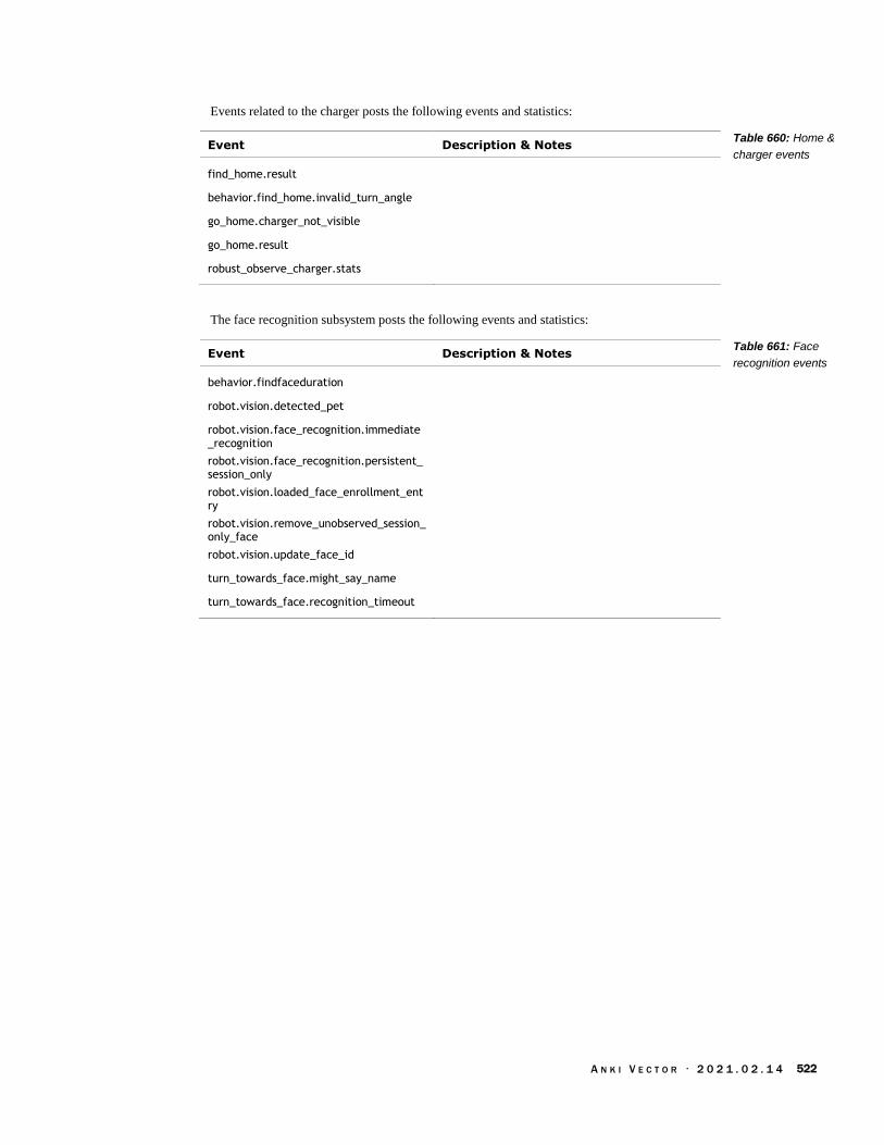
A N K I V E C T O R · 2 0 2 1 . 0 2 . 1 4 522
Events related to the charger posts the following events and statistics:
Event Description & Notes
find_home.result
behavior.find_home.invalid_turn_angle
go_home.charger_not_visible
go_home.result
robust_observe_charger.stats
The face recognition subsystem posts the following events and statistics:
Event Description & Notes
behavior.findfaceduration
robot.vision.detected_pet
robot.vision.face_recognition.immediate_recognition
robot.vision.face_recognition.persistent_session_only
robot.vision.loaded_face_enrollment_entry
robot.vision.remove_unobserved_session_only_face
robot.vision.update_face_id
turn_towards_face.might_say_name
turn_towards_face.recognition_timeout
Table 660: Home &
charger events
Table 661: Face
recognition events
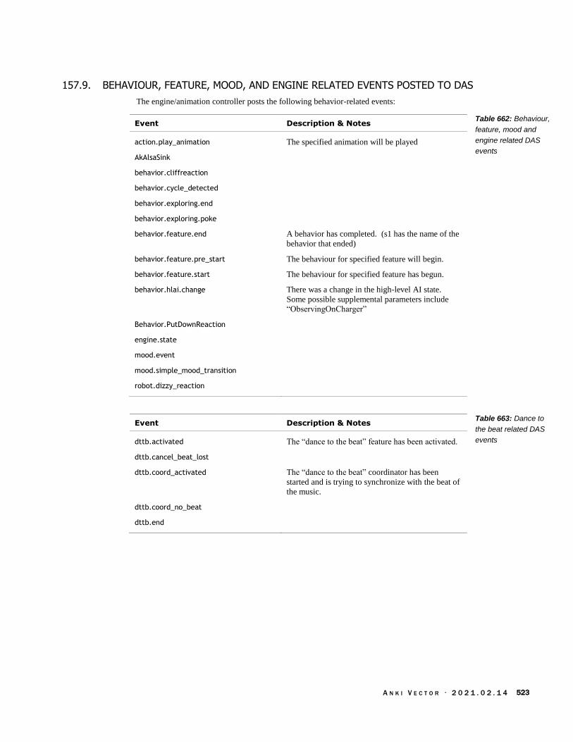
A N K I V E C T O R · 2 0 2 1 . 0 2 . 1 4 523
157.9. BEHAVIOUR, FEATURE, MOOD, AND ENGINE RELATED EVENTS POSTED TO DAS
The engine/animation controller posts the following behavior-related events:
Event Description & Notes
action.play_animation The specified animation will be played
AkAlsaSink
behavior.cliffreaction
behavior.cycle_detected
behavior.exploring.end
behavior.exploring.poke
behavior.feature.end A behavior has completed. (s1 has the name of the
behavior that ended)
behavior.feature.pre_start The behaviour for specified feature will begin.
behavior.feature.start The behaviour for specified feature has begun.
behavior.hlai.change There was a change in the high-level AI state.
Some possible supplemental parameters include
“ObservingOnCharger”
Behavior.PutDownReaction
engine.state
mood.event
mood.simple_mood_transition
robot.dizzy_reaction
Event Description & Notes
dttb.activated The “dance to the beat” feature has been activated.
dttb.cancel_beat_lost
dttb.coord_activated The “dance to the beat” coordinator has been
started and is trying to synchronize with the beat of
the music.
dttb.coord_no_beat
dttb.end
Table 662: Behaviour,
feature, mood and
engine related DAS
events
Table 663: Dance to
the beat related DAS
events

A N K I V E C T O R · 2 0 2 1 . 0 2 . 1 4 524
APPENDIX M
Pleo
The Pleo, sold in 2007 – a decade prior to Vector – has many similarities. The Pleo was a soft-
skinned animatronic baby dinosaur created by Caleb Chung, John Sosuka and their team at Ugobe.
Ugobe went bankrupt in 2009, and the rights were bought by Innvo Labs which introduced a
second generation in 2010. This appendix is mostly adapted from the Wikipedia article and
reference manual.
Sensing for interacting with a person
Two microphones, could do beat detection allowing Pleo to dance to music. The second
generation (2010) could localize the sound and turn towards the source.
12 touch sensors (head, chin, shoulders, back, feet) to detect when petted,
Environmental sensors
Camera-based vision system (for light detection and navigation). The first generation
treated the image as gray-scale, the second generation could recognize colors and patterns.
Four ground foot sensors to detect the ground. The second generation could prevent falling
by detecting drop-offs
Fourteen force-feedback sensors, one per joint
Orientation tilt sensor for body position
Infrared mouth sensor for object detection into mouth, in the first generation. The second
generation could sense accessories with an RFID system.
Infrared detection of objects
Two-way infrared communication with other Pleos
The second generation include a temperature sensor
Annuciators and Actuators
2 speakers, to give it sounds
14 motors
Steel wires to move the neck and tail (these tended to break in the first generation)
The processing
Atmel ARM7 microprocessor was the main processor.
An NXP ARM7 processor handle the camera system, audio input
Low-level motor control was handled by four 8-bit processors

A N K I V E C T O R · 2 0 2 1 . 0 2 . 1 4 525
A developers kit – originally intended to be released at the same time as the first Pleo – was
released ~2010. The design included a virtual machine intended to allow “for user programming
of new behaviors.”89
157.10. SALES
Pleo’s original MSRP was $350, “the wholesale cost of Pleo was $195, and the cost to manufacture
each one was $140” sold ~100,000 units, ~$20 million in sales90
The second generation (Pleo Reborn) had an MSRP of $469
157.11. RESOURCES
Wikipedia article. https://en.wikipedia.org/wiki/Pleo
iFixit’s teardown. https://www.ifixit.com/Teardown/Pleo+Teardown/597
Ugobe, Pleo Monitor, Rev 1.1, 2008 Aug 18
Ugobe, Pleo Programming Guide, Rev 2, 2008 Aug 15
89 https://news.ycombinator.com/item?id=17755596 90 https://www.idahostatesman.com/news/business/article59599691.html
https://www.robotshop.com/community/blog/show/the-rise-and-fall-of-pleo-a-fairwell-lecture-by-john-sosoka-former-cto-of-ugobeJohn Sosoka