szent istvÁn university parameters and flow …
TRANSCRIPT

SZENT ISTVÁN UNIVERSITY
Parameters and flow circumstances of working media of solar liquid collectors
Theses of PhD work
Károly Hegyi
Gödöllő, Hungary 2009

Doctoral school denomination: Mechanical Engineering PhD School
science: Energetics of Agriculture
leader: Prof. Dr. István Farkas
Dr. of Technical Sciences
Faculty of Mechanical Engineering
Szent István University, Gödöllő, Hungary
supervisor: Prof. Dr. István Farkas
Dr. of Technical Sciences
Institute for Environmental System
Faculty of Mechanical Engineering
Szent István University, Gödöllő, Hungary
……………………………………… ……………………………………… affirmation of program leader affirmation of supervisor
2

CONTENTS
1. INTRODUCTION……………………………………………………….… …4 1.1 Importance of the topic……………….………………………….. …4 1.2 Aim of the work……………………………………………….… …..5 2. MATERIAL AND METHOD…...……………………………………… ……6 2.1 The solar fluid ……..…..……………………...… .…6 2.2 Measuring the density of solar fluid…………………………….. ..6 2.3 Measuring the viscosity of solar fluid…………………………..……6 2.4 Measuring the thermal conductivity of solar fluid………………….7 2.4.1 Mathematical model of the instrument……………………..8 2.5 Measuring the specific heat of solar fluid………………………..…8 2.6 Measuring the refraction index of solar fluid…………………….…9 3. RESULTS……..……………………………………………………...…… ….9 3.1 Results for density…………………..……..… …...…9 3.2 Results for viscosity…………………………………………..... …..10 3.3 Results for thermal conductivity……………………………… …..11 3.4 Results for specific heat ……………………… ….13
3.5 Results for refraction index…………..……...……. …..….15 3.6 Flows of collectors..……………………………………… ….16 3.7 Effects of collectors on solar fluid....……………….. …..17 4. NEW SCIENTIFIC RESULTS……….………………….…………………..19 5. CONCLUSIONS AND SUGGESTIONS…..………………………………..22 6. SUMMARY……….…………………………………………………….. ..…23 7. PUBLICATIONS RELATED TO THE PHD WORK………...………. ……24
3

1. INTRODUCTION
1.1. Importance of the topic Examined the types of energy it can be said, that our energy production is based on fossil energy sources. These stores are running down, their prices are increasing.
In the last few years problems of pollution in connection with energy production have increased, as well. The increasing CO2 level generates a growing average temperature on Earth caused by greenhouse effect. The NOx and SO2 could cause the end of biosphere by acid rain. The world sees solution in renewable energy sources, such as solar energy and its indirect forms: the biomass, wind, geothermal energy and hydraulic energy.
The Faculty of Mechanical Engineering of Szent István University has been researching the renewable energy sources. Many works are done in these topics in PhD School (wind energy, biomass, solar drying, etc.) The Department of Physics and Process Control of the Faculty of Mechanical Engineering primarily has been dealing with the direct use of solar energy for more than 15 years. These all indicated a centre of researching, teaching and demonstrating solar energy, which was built on the Department. Besides the weather station there are solar collector, solar drier, photovoltaic panels and transparent insulation wall. Achievements on renewable energy researches – especially solar energy researches – are appreciated in Hungary and in the world as well.
The two most important branches of direct use of solar energy are: photovoltaic cells (solar cells, PV cells) and solar collectors for producing domestic hot water. Unfortunately, solar modules are rather expensive (about 1 million HUF/kW), so they are not profitable to invest, but these are to be the most important in using solar energy.
Solar collectors for producing domestic hot water are already profitable. Their payback time is about 5-8 years. Their working process is simple. Sunlight has been used for heating water for a long time. Avoiding winter freezes, double circle collectors are used in most of the cases. Sun heats an antifreeze fluid. With a heat-exchanger the fluid warms the domestic water. In most of the cases this fluid based on propylene glycol. Ethilglycol is forbidden to use because it is toxic, and it could get into the domestic water in case of system failure. Propylene glycol is not poisonous, and it is already used in food industry.
Improving the efficiency of solarcollectors is an actual problem to solve. But for thermotechnical examination and development the physical properties of propylene glycol are needed, and the accessible documentary is incomplete as far as these parameters are concern.
4

1.2. Aim of the work I aimed to determine the most important physical parameters of propylene glycol and its effects to collectors. I examined solution of water and propylene glycol, so called solar fluid. During the work I intended to determine the following parameters of the fluid:
• Density • Dynamic viscosity • Refraction index • Thermal conductivity • Specific heat • Photocolorimetric features
I determined these parameters of the solar fluid by using available instruments, but sometimes I had to improve or create the instrument itself. Basically I intended to examine changes of the physical parameters at different rate of solution with water and at different temperature. As the efficiency of the collector is concern, the aimed parameters are the most important, so I didn’t intend to examine others (electro-magnetic, chemical, etc.) With parameters determined this way I planned to examine the flow of a certain collector and the effects caused in the collector by these parameters. I wish to make some notes on the parameters:
• The consistence of the solar fluid (solution of water and propylene glycol) is usually given in volume percentage. To be able to give the mass-percent as well, the knowledge of density of the fluid is necessary.
• As the flow is concern, the most important physical parameter is the viscosity. I will explain the importance of laminar or turbulent flow later in my work. It is important for the heat-changing method. For turbulent flow the Reynolds number is necessary, which contains the viscosity as well.
• With the refraction index the water content in the fluid can be determined very precisely. This content has effects to every physical parameter.
• Knowledge of thermal conductivity is essential when examining a thermotechnical instrument.
• Similarly, the specific heat – as basic thermal parameter – determines the work of the collector.
• The colour of the fluid has conspicuously changed after flowing for years in the instrument (it turned into brown). So I planned to examine the colorimetric features of the fluid, compared to the wave-length of the light.
• In case of certain system failures the fluid could reach higher temperature than the working temperature. I intended to examine this problem, as well.
5

The physical parameters of the solar fluid have effects on the energy production of the collector. In every collector the speed of the fluid can be changed by the circulating pump. At small speed the flow is laminar, at greater speed the flow can turn to turbulent (the limit is changing in different parts of the collector). When laminar, energy transfer is carried out by thermal conduction, when turbulent, the flow of heat will be more efficient. (In small amount the thermal conduction will be remarkable). As laminar–turbulent transition depends on the Reynolds number, the physical parameters have effects on this transition. I aimed to examine the effects of the parameters of the fluid on flow, especially on turbulent flow. I planned to examine the changed (brown) colour of the fluid primarily with photo colorimeter and whether overheating causes any changes in the fluid of not.
2. MATERIAL AND METHOD 2.1 The solar fluid I examined the solar fluid, which is a solution of propylene glycol and water. The propylene glycol is 1.2 propylene glycol, precisely.
Its other names are: 1.2 propanediol, 1.2 dihidroxi-propane, or monopropylene-glycol (MPG)]
Its formula is: C3H8O2
CH3 C C OH
H H
H OH
Its atomic formula is:
Point of congelation: -60 °C
2.2 Measuring the density of solar fluid
I used the Mohr-Westphal scales to measure the density. These scales use the law of Archimedes.
2.3 Measuring the viscosity of solar fluid To get to know the rheological type of the solar fluid, we have to know the flow-diagram of the fluid (function of shearing speed and shearing stress). So first I measured the viscosity of undiluted solar fluid. I used a Rheotest rotating viscosymeter and the evaluating software for the instrument. Based on measurements, the propylene glycol is a Newtonian liquid. For further measuring, I used Höppler viscosymeter, in function of dilution and temperature. This instrument is a falling weight viscosymeter.
6

2.4 Measuring the thermal conductivity of solar fluid For determining the thermal conductivity I chose stationer method. The instrument, that I created, is very accurate because of the relative measuring method.
Diagram 1 shows the construction of the instrument. The upper end of the vertical, thin cylinder is filled with plex (a transparent, hard plastic) whose thermal conductivity is at the same magnitude as the conductivity of the fluid. Under the plex there is fluid in a thin layer. The plex and the fluid are in connection with copper cylinders. (The thermal conductivity of copper is much larger as the magnitude of the fluid’s.)
Hot water out
Hot water in (from thermostat)
Diagram 1: Construction of the instrument for measuring thermal conductivity
To avoid the heat transfer, the temperature of the upper copper cylinder (TA) is higher than the lower (TB).
I kept the temperatures of the copper cylinders constant by ultrathermostates. To keep the temperature of the lower copper cylinder under 20°C, I needed to place a Peltier cell between the copper cylinder and the cold water. I measured the upper and lower temperature, and the border of the plex and the fluid with thermocouples (TC). The thermocouples are on the axis of the cylinder. I tested their places with the mathematical model of the instrument. I used distilled water as reference liquid, because its data are reachable and precise.
Cold water in (from the thermostat)
Cold water out Peltier
Copper cylinders
Copper plex
TA
fluid
TC
TB
7

The voltage of the thermocouples were read to the computer by a PCL-812 PG panel.
2.4.1 The mathematical model of the instrument
To examine the sensibility of the middle measuring point and the usability of the the instrument. This is the heat instrument, I solved the mathematical model of
transfer equation in cylinder-coordinate form:
( ) ⎟⎠
⎜⎝
+⎟⎠ yy ∂
λ∂
,
where λ is thermal conductivity, ρ is density, T is the absolute temperature and cp is the specific heat.
pical solution to the distribution of the temperature is shown on
⎟⎞
⎜⎛
⎟⎞
⎜⎜⎝
⎛=
TrTr
rrTc
t p∂∂
∂∂λ
∂∂ρ
∂∂ 1
At these conditions the equation cannot be solved analytically, I calculated numerically. A tyDiagram 2. The solution of the mathematical model proves – among other things – that at the border of the two materials the temperature measured on the axis is not sensible to removing the thermocouples few millimetres. (Calculation was done under Neumann and Dirichlet conditions.)
Diagram 2: Distribution of temperature in the mathematical model of the
instrument
2.5 M
calorimeter, with relative method. and measured the temperature in
easuring the specific heat of solar fluid
I measured the specific heat of the solar fluid by heated the liquid in the calorimeter electrically I
every second. I used the same instrument as was used for heat transfer measurements. The mass and specific heat of the calorimeter and its supplementary
8

parts are unknown and practically unable to measure, so I chose the relato measure. For standard material I chose distilled water, because its thermal properties are reachable and precise. 2.6 Measuring the refraction index
tive method
of the solar fluid
e the refraction index. I sed an Abbe-type refractometer, with which the refraction index can be
ith
3.1 Results for density
To determine precisely the ratio of dilution we should usudetermined very precisely based on the determination of total reflection angle. Wthis instrument indexes from 1.3 to 1.7 can be measured by 0.2% error.
3. RESULTS
y = -0,0067x2 + 1,172x + 999,06R2 = 0,9988
9901000101010201030104010501060
0 20 40 60 80 100
dilution (%)
dens
ity (k
g/m
3)
Diagram 3: Density of solar fluid depending on dilution on 20°C
I calculat °C):
where 0<α<1 is the por ylene glycol
ed the following equation for density depending on dilution (on 20
ρ(α ) = -66,892 α2 + 117,2α + 999,06,
tion of dilution, α =1 is undiluted prop
9

3.2 Results for dynamic viscosity A typical result is shown on Diagram 4.
0,00
1,00
2,00
3,00
4,00
5,00
6,00
7,00
8,00
0 20 40 6 0 80
temp erat ure ( C )
visc
osity
(mPa
s)
100
Diagram 4: Dynamic viscosity of 50% solar fluid depending on temperature
I adopted the ARRHENIUS - ANDRADE – GUZMAN equation based on literature:
0
ERTeη η=
As I took logarithm of both sides, I got the following typical curve as result. (Diagram 5)
y = 4354,7x - 17,724R2 = 0,9969
-7-6-5-4-3-2-100,0025 0,0027 0,0029 0,0031 0,0033 0,0035
1/T
ln (e
ta)
Diagram 5: Viscosity of undiluted solar fluid depending on the reciprocal of
temperature So to undiluted solar fluid (propylene glycol):
4354,78
100 2,0071 10 Teη −= ⋅
10

To 50% diluted solar fluid: 2728,7
750 5,5295 10 Teη −= ⋅
Results for viscosity activating energy for both fluids:
E100= 36,19 kJ/mol
E50=22,67 kJ/mol. (3.5% error)
I calculated polynomial fits from the different measures for the viscosity depending on temperature and on dilution. (Table 1)
2( , ) ( ) ( ) ( )t A t B t Cη η ηη α α α= ⋅ + ⋅ + α , where the coefficients
coefficient Dependence of coefficients on dilution Correlation coefficient
Table 1: Coefficients of viscosity depending on dilution
Aη(α) = 0,0249 α2 - 0,0108 α + 0,0007 R2=0,9795
Bη(α) = - 4,0786 α2 + 1,8685 α - 0,1268 R2=0,9885
Cη(α) = 165,89 α2- 77,335 α + 5,7668 R2=0,9767
α- portion of dilution (0<α <1)
By statement seen above the coefficients of 50% solar fluid (α=0.5) are:
Aη (0.5)=1,525 10-3 mPas/ºC2 Bη (0.5)=0,2122 mPas/ºC Cη(0.5)=8,5718 mPas
3.3 Results for thermal conductivity A typical result can be seen for measuring heat transfer on Diagram 6. During measuring the stationer stage fixes in 10 minutes. The middle temperature converges asymptotically to the stationer temperature (∆t<0.1 ºC).
11

Solar fluid
0102030405060708090
1 85 169 253 337 421 505 589 673 757 841
time (s)
tem
pera
ture
(C)
Upper temperatureMiddle temperatureLower temperature
Diagram 6: Typical temperature dependence on time, with thermal conductivity
coefficients
By knowing λwater=0,5873 W/mK, the coefficient of the thermal conductivity of undiluted solar fluid will be 0,2227 W/mK (at 50°C). The thermal conductivity depending on dilution could be approached by a linear function very well (R2=0,9947).
λ= - 0,3766 α + 0,5876 [λ]=W/mK, 0<α<1
12

Heat transfer y = -0,3766x + 0,5876R2 = 0,9947
00,20,40,60,8
0 0,2 0,4 0,6 0,8 1
Portion of dilution (propileneglykol/water)
Ther
mal
co
nduc
tivity
Diagram 7: Thermal conductivity depending on dilution 3.4 Results for specific heat Diagram 8 shows a typical result of measuring temperature of 50% solar fluid during heating.
specific heat-50 %
y = 0,0127x + 27,924R2 = 0,9949
020406080
100120
0 1000 2000 3000 4000 5000
time (s)
tem
pera
ture
(C)
Diagram 8: Temperature of calorimeter depending on time (with 50% solar fluid)
13

specific heaty = -19,643x + 4176,4
R2 = 0,9991
010002000300040005000
0 20 40 60 80 100
portion of dilution (%)
spec
ific
heat
(J/k
gK)
Diagram 9: Specific heat of solar fluid depending on dilution
Determining the specific heat at different dilutions I got results shown on Diagram 9, which implicated the following statement:
c(α )= -19,643α + 4176,4
where α is the ratio of dilution (0<α<1), c is the specific heat of the solar fluid [c]=J/kgK.
14

3.5 Results for refraction index Diagram 10 shows the optical refraction index of different dilutions of solar fluid on 20°C.
Refraction index of solar fluid
1,3
1,35
1,4
1,45
0 20 40 60 80 1ratio of dilution
(percentage of undiluted solar fluid)
refra
ctio
n in
dex
00
Diagram 10: Refraction index of solar fluids depending on dilution (20°C) It can be seen on the diagram and known from the correlation coefficient (R2= 0,9947), that refraction index is changing in direct proportion with dilution. In Diagram 11 the refraction index of 50% solar fluid is drawn depending on temperature. Other dilutions produce similar data, they also have linear curve.
y = -0,0003x + 1,3952R2 = 0,9988
1,365
1,37
1,375
1,38
1,385
1,39
0 20 40 60 80 100
Diagram 11: Refraction index of solar fluid depending on temperature Based on measurements my statements can be read in the chapter „New scientific results”. Because usually measurement is at 20°C,
n = 0,1033 α +1,3347 [n]=[α]=1. α: ratio of dilution (0<α<1), n: refraction index
15

3.6 Flows of collectors I calculated the laminar-turbulent transfer on a plane-collector shown on Diagram 12.
Diagram 12: SKV solar-collector
The heat gathered in the collector is transferred on 6 tubes filled with solar fluid. Their cross-section is 60 mm2 each. The collector is connected to a boiler 20 m from it by a copper tube, 18x1 mm. For the calculations I took the tubes hydraulically smooth. I calculated the hydraulic resistance of the collector and the tube going to the collector. When the flow is laminar (Reynolds number <2320), I used the
264R e
lpd
ρ∆ =
2v , when turbulent, 2lp
dvρ
∆ = λ2
equation and calculated with the
Blasius number, where -0.25Reλ = 0.3164 - ∆p – pressure difference between the two ends of the tube - l, d – length and diameter of the tube - ρ – density of fluid - η – dynamic viscosity of the fluid - v – average speed of fluid
- vdρRe =η
– Reynolds number
16

Diagram 13: Speed division of solar fluid calculated by ANSYS program I calculated the pressure drop of the collector and on the tube depending on the volume of the fluid. I used all of my results of viscosity in both cases, and calculated with 50°C, 50% solar fluid. The laminar-turbulent transition at tubes should be regarded after entering point in the transient part (Lt). Its values (Re – Reynolds number, d – diameter of tube): Lt=Cl·Re·d, when laminar, where Cl=0,06…0,029 Lt= Ct ·d, when turbulent, where Ct=50 …100 Results can be seen on Diagram 16 in chapter „New scientific results”. I made calculations on similar collectors with ANSYS program, one of the results is shown on Diagram 13. 3.7 Effects of collectors on the solar fluid Fluid from collector has turned brown after years. I have done photocolorimetrical measures to examine this symptom. I measured the optical absorption of the solar fluid. I filtered the fluid first with 0.45 µm filter, then with pressure filter. Diagram 14 shows the absorptions of these fluids. I diagnosed that the brown colour is caused by corrosion (first filtering), but there are other reasons.
17

absorbtion
0
20
40
60
80
100
400 450 500 550 600
wave lenght (nm)
abso
rbtio
n (%
)
brownfiltereddouble filtered
Diagram 14: Absorption depending on wave-length, on twice filtered used solar
fluid
difference in absorbtion
0
20
40
60
300 350 400 450 500 550 600 650 700
wave length (nm)
abso
rbtio
n di
ff. (%
)
Diagram 15: Absorption difference between clean and heated, undiluted solar fluid I heated solar fluid under pressure and measured the degree of optical absorption. Results are shown on Diagram 15.
18
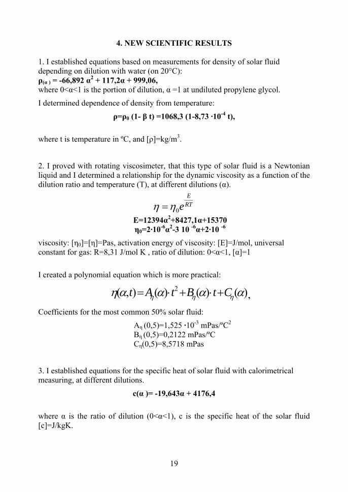
4. NEW SCIENTIFIC RESULTS
1. I established equations based on measurements for density of solar fluid depending on dilution with water (on 20°C): ρ(α ) = -66,892 α2 + 117,2α + 999,06, where 0<α<1 is the portion of dilution, α =1 at undiluted propylene glycol.
I determined dependence of density from temperature:
ρ=ρ0 (1- β t) =1068,3 (1-8,73 ·10-4 t),
where t is temperature in ºC, and [ρ]=kg/m3.
2. I proved with rotating viscosimeter, that this type of solar fluid is a Newtonian liquid and I determined a relationship for the dynamic viscosity as a function of the dilution ratio and temperature (T), at different dilutions (α).
0
ERTeη η=
E=12394α2+8427,1α+15370 η0=2·10-6α2-3 10 -6α+2·10 -6
viscosity: [η0]=[η]=Pas, activation energy of viscosity: [E]=J/mol, universal constant for gas: R=8,31 J/mol K , ratio of dilution: 0<α<1, [α]=1
I created a polynomial equation which is more practical:
2( , ) ( ) ( ) ( )t A t B t Cη η ηη α α α= ⋅ + ⋅ + α ,
Coefficients for the most common 50% solar fluid:
Aη (0,5)=1,525 ·10-3 mPas/ºC2 Bη (0,5)=0,2122 mPas/ºC Cη(0,5)=8,5718 mPas
3. I established equations for the specific heat of solar fluid with calorimetrical measuring, at different dilutions.
c(α )= -19,643α + 4176,4
where α is the ratio of dilution (0<α<1), c is the specific heat of the solar fluid [c]=J/kgK.
19

4. To determine the thermal conductivity of the solar fluid, I created an instrument. I proved the usability of the instrument with numerical calculations based on heat transfer equation. I created equations for the thermal conductivity of the solar depending on dilution (α):
λ= - 0,3766 α + 0,5876 [λ]=W/mK, 0<α<1
5. I created to the refraction index of the solar fluid (n) with Abbe refractometer depending on the temperature (t) and ratio of dilution (α):
n = An(α) t + Bn(α) where An(α) = - 0,0002 α2 -0,0004 α – 0,0002
and Bn(α) = 0,1 α + 1,3397.
Because we usually measure at 20°C, I created a linear equation (relative error δ=0,2%):
n = 0,1033 α +1,3347 [n]=[α]=1.
6. At flat plane-collectors and with physical parameters I measured, I calculated the laminar-turbulent transition point for 50% solar fluid. I determined the optimal output to reach better heat transfer and efficiency (2·10-4 m3/s).
20

Drop of pressure
0
0,5
1
1,5
2
2,5
3
3,5
0 0,05 0,1 0,15 0,2 0,25 0,3 0,35
Intensity (10-3 m3/s)
Pressure (kPa)
water solarfluid
Diagram 16: Laminar-turbulent transfer at suncollectors
7. I proved with photocolorimetrical measuring and mikrofiltering, that used solar fluid turns to brown because of corrosion and over-heating. I determined that heating the solar fluid causes the greatest increase of optical absorption in 350-400 nm wave-length intervall.
21

5. CONCLUSIONS AND SUGGESTIONS
It seems that every circumstance is in favour of renewable energy sources. Questions on environment are getting more important, prices of fossil energy sources are increasing. Domestic water is a great part of household’s energy, so it is needed for the collectors to be spread. Lower prices could be reached by for example decreasing or deleting VAT for instruments using renewable energy. International trends could allow sources from EU to be joined. All of these are duty of politicians. People dealing with this problem are to solve professional questions and to inform politicians and to lobby for the aims mentioned above. Later on it would be useful to examine the dependence of thermal conductivity and specific heat from temperature with detailed measurements. Development of computers enables us to examine the flows of collectors in more detail with for example ANSYS CFX. By simulating programs for flows, conditions that start heat convection should be examined at instruments used for measurements of thermal conductivity (thickness of layers, geometric data, etc.). With more used solar fluid the product of corrosion should be examined more carefully. With the help of the collector on the Department of Physics and Process Controll, with appropriate pressure and flow-controlling detectors the role of flows has effects on the efficiency of the collector should be proved by measuring. Knowing the physical parameters of the solar fluid, the structure of the collectors should be reconsidered. It seems, plane-collectors were designed in an “ad hoc” way. More things should be reconsidered, for example the absorber tubes, their number and place in the collector, for the optimal efficiency.
22

6. SUMMARY The use of renewable energy sources has great actuality nowadays. We are running out of some fossil energy sources, the usage of them generates serious climatic effects because of the greenhouse gas emission. In long term the photovoltaic modules can play significant role in the electrical energy production, but now they are very expensive yet and their efficiency is low. The domestic hot water production by solar energy is profitable already now. However for the design, for the development of the collector efficiency and for achieving optimal operating conditions it is necessary to know the physical properties of the solar liquid (the heat transport medium). In the literature very few data can be found on this topic. During my research the next goals could be reached:
• I measured the density of the solar liquid and I established a relationship for the density as a function of the temperature and dilution ratio.
• By examining the rheological characteristic of the solar liquid, I concluded that it is a Newtonian liquid and I determined a relationship for the dynamic viscosity as a function of the dilution ratio and temperature.
• If the viscosity is known, the Reynolds number – which is an important indicator of the quality of the flow – can be determined, and based on this the critical speed, where the laminar flow changes to turbulent one can be allocated. By knowing this critical value, the efficiency of the solar collectors can be developed. I determined the critical laminar – turbulent transition speed for a specific solar collector.
• The most exact method to determine the dilution ratio of propylene glycol is the use of optical measurement. By a refractometer I determined a relationship for the refraction index as a function of the dilution ratio and temperature.
• The knowledge of the thermal conductivity is essential for the thermal processes. I developed a measuring equipment together with the interpreter electronics for determining this quantity. I set up a mathematical model for determining the thermal conductivity from the measured data.
• The specific heat of the thermal liquid is also essential, hence I developed a formula for the dilution ratio dependence of the specific heat.
• The colour of the solar liquid used for longer time in collectors changes to brown. By photocolorimetry and micro filtration I concluded the two reasons of the effect: the corrosion and the heat shock. For describing the movement of the corrosion particles I developed a mathematical model. I simulated the heat shock process and generated the browning effect.
I hope that my research results can help the development of the solar collectors and to optimize the operations of them.
23

7. PUBLICATIONS RELATED TO THE PHD WORK 1. Hegyi K. (1985): A szűréselmélet és mezőgazdasági alkalmazása. (egyetemi
doktori disszertáció, Gödöllő, 1985. 130 p.)
2. Vincze Gy., Hegyi K., Vékony., Seres I. (1989): Hőmérsékletmérés termopárral hidegpont nélkül MTA-MÉM Agrár-Műszaki Bizottság Kutatási Tanácskozása. A mezőgazdaság gépesítése. VI. szekció. Gödöllő, 1989. I. 17-18.
3. Vincze Gy., Hegyi K. (1993): Részecskekollektívumok szedimentációs folyamatának vizsgálata ülepítőtartályban. MTA-MÉM Agrár-Műszaki Bizottság Kutatási Tanácskozása. A mezőgazdaság gépesítése. VI. szekció. Gödöllő, 1993. I. 18-20.
4. Vincze Gy., Hegyi K., Bencsik T., Dudás J. (1994): RHEOTEST 2. viszkoziméter alkalmazása nemnewtoni folyadékok vizsgálatára. MTA-MÉM Agrár-Műszaki Bizottság Kutatási Tanácskozása. A mezőgazdaság gépesítése. VI. szekció. Gödöllő, 1994.
5. Farkas I., Buzás J., Hegyi K. KardonB., Seres I., (1995): Napenergia mezőgazdasági hasznosítása. Megújuló energiaforrások hasznosítási lehetőségei Magyarországon, Magyar-EU Energia Központ Tanulmány 6. fejezet, Budapest, 1995.
6. Hegyi K., Farkas I. (1995): Hagyományos és megújuló energiaforrások összehasonlítása különböző mezőgazdasági technológiáknál. (előadás) MTA-MÉM Agrár-Műszaki Bizottság Kutatási Tanácskozása. A mezőgazdaság gépesítése. VI. szekció. Gödöllő, 1995. I. 17-18. p.28.
7. Hegyi K. (1995): Tanyák energiaellátása megújuló energiaforrások felhasználásával. MTA Agrár-Műszaki Bizottság Kutatási Tanácskozása. A mezőgazdaság gépesítése. VI. szekció. Gödöllő, 1995. I. 17-18.
8. Hegyi K.-Farkas I. (1995): Hagyományos és megújuló energiaforrások összehasonlítása különböző mezőgazdasági technológiáknál. MTA Agrár-Műszaki Bizottság, Kutatási és Fejlesztési Tanácskozás, Gödöllő, 1995. jan. 17-18, 1. kötet, p. 421-424.
9. Hegyi K.-Farkas I. (1995): Megújuló és hagyományos energiaforrások mezőgazdasági felhasználása és oktatásának kérdései. INTACT '95, Környezetvédelmi Kongresszus és Kiállítás, I. kötet, 1. Budapest, 1995. márc. 21-24, p. 102-109.
10. Farkas I.-Hegyi K. (1995): Hagyományos és megújuló energiaforrások a mezőgazdaságban, Magyar Energetikai Társaság, Energia Fórum 95, Szeged, 1995. ápr. 24-26. (Megjelent a Magyar Energetika, 1995/6 sz., p. 23-26.)
11. Farkas I., Hegyi K., Kardon B., Seres I. (1995): Development of a standalone PV power system for remote villages making use of pumped water energy
24

storage, Contribution Report to the concept proposed for the Romanian sites, Department of Physics and Process Control, University of Agricultural Sciences, Gödöllő, Hungary, No. 2, June 1995.
12. Farkas I., Bencsik T., Buzás J., Hegyi K., Kardon B., Seres I. (1995): Napenergia kommunális célú hasznosításának lehetőségei, Esettanulmány, Gödöllő Város Önkormányzata, No. 3, Gödöllő, 1995. okt.
13. Hegyi K. (1995): Renewable Energy for Remote Farms. Anniversary Seminar on Energy and Environment, Gödöllő, 1995. IX. 27-30.
14. Farkas I., Buzás J., Hegyi K., Kardon B., Seres I. (1995): Napenergia mezőgazdasági hasznosítása. Megújuló energiaforrások hasznosítási lehetőségei Magyarországon. Magyar-EU Energia Központ Tanulmány 6. fejezet, Budapest, 1995.
15. Farkas I., Hegyi K., Kardon B., Seres I. (1995): Development of a standalone PV power system for remote villages making use of pumped water energy storage. Contribution Report to the concept proposed for the Romanian sites, Department of Physics and Process Control, University of Agricultural Sciences, Gödöllő, Hungary, No. 2, June 1995.
16. Farkas I., Bencsik T., BuzásJ., Hegyi K., Seres I. (1995): Application possibilities of a PV energy supply system combined with water storage in Hungary, International Conference on Rational Use of Renewable Energy Sources in Agriculture, in connection with the Environmental Control, 1995. June 2-8, Budapest, Hungary, p. 71.
17. Farkas I., Buzás J., Hegyi K., Kardon B., Seres I. (1995): Napenergia mezőgazdasági hasznosítása. Megújuló energiaforrások hasznosítási lehetőségei Magyarországon, Magyar-EU Energia Központ Tanulmány 6. fejezet, Budapest, 1995.
18. Farkas I., Bencsik T., Buzás J., Hegyi K., Seres I. (1996): Development of a standalone PV power system for remote villages making use of pumped water energy storage, Feasibility study on potential Hungarian sites, Department of Physics and Process Control, University of Agricultural Sciences, Gödöllő, Hungary, No. 4, January 1996.
19. Farkas I., Bencsik T., Buzás J., Hegyi K., Seres I. (1996): PV operated energy and water supply system in a grape farm. EuroSun'96, Proceedings, Vol. 2, Freiburg, 1996. p. 655-659.
20. Farkas I., Bencsik T., Buzás J., Hegyi K., Seres I. (1996): Development of a standalone PV power system for remote villages making use of pumped water energy storage, Feasibility study on potential Hungarian sites, Department of Physics and Process Control, University of Agricultural Sciences, Gödöllő, Hungary, No. 4, January 1996.
25

21. Farkas I., Bencsik T., Buzás J., Hegyi K., Lágymányosi A., Seres I. (1996): Development of a standalone PV power system for remote villages making use of pumped water energy storage, Feasibility study on grape farm applications, Department of Physics and Process Control, University of Agricultural Sciences, Gödöllő, Hungary, No. 5, April 1996.
22. Farkas I., Bencsik T., Buzás J., Hegyi K., Seres I. (1996): Application possibilities of a PV energy supply system combined with water storage in Hungary, International Conference on Rational Use of Renewable Energy Sources in Agriculture, in connection with the Environmental Control, 1996. June 2-8, Budapest, Hungary, p. 71.
23. Hegyi K. (1996): Small farms powered by renewable energy. Seminar on Energy and Environment, Gödöllő,1996. IX. 3-6.
24. Farkas I., Bencsik T., Buzás J., Hegyi K., Seres I. (1996): PV operated energy and water supply system in a grape farm. EuroSun'96, Proceedings, Vol. 2, Freiburg, 1996. p. 655-659.
25. Hegyi K., Fekete M., Farkas I., Buzás J. (1997): Application of the renewable energy sources to the rural tourism, 3rd Seminar on Energy and Environment, Gödöllő, Hungary, November 10-12, 1997. p. 8.
26. Hegyi K. (1997): Villamos hálózatok felújítása a megújuló energiaforrások felhasználásával. MTA Agrár-Műszaki Bizottság Kutatási Tanácskozása. A mezőgazdaság gépesítése VI. szekció, Gödöllő, 1997. I. 21-22
27. Hegyi K., Farkasné Fekete M., Farkas I., Buzás J. (1997): Megújuló energiaforrások és a fenntartható fejlődés a magyar mezőgazdaságban, Vállalati környezet és alkalmazkodás az élelmiszertermelésben c. konferencia, Gödöllő, 1997. okt. 9-10.
28. Hegyi K., Fekete M., Farkas I., Buzás J. (1997): Application of the renewable energy sources to the rural tourism, 3rd Seminar on Energy and Environment, Gödöllő, Hungary, November 10-12, 1997. p. 8.
29. Hegyi K., Farkasné Fekete M., Farkas I., Buzás J. (1998): Megújuló energiaforrások és a fenntartható fejlődés a magyar mezőgazdaságban. Gödöllői Agrártudományi Egyetem, Gazdaság- és Társadalomtudományi Kar, Tudományos Közlemények 2., 1998. p. 13-18.
30. Farkas I., Bencsik T., Buzás J., Hegyi K., Seres I. (1998): Víztározóval kiegészített fotovillamos energiatermelő rendszerek telepíthetősége, Magyar Energetika, VI. évf., 1998/1. sz., p. 25-29.
31. Hegyi K., Farkasné Fekete M., Farkas I., Buzás J. (1998): Megújuló energiaforrások felhasználása a falusi turizmusban. VI. Nemzetközi Agrárökonómiai Tudományos Napok, Gyöngyös, 1998. márc. 24-25, 2. kötet, p. 67-72.
26

32. Farkas I., Biró A., Buzás J., Hegyi K., Lágymányosi A., Seres I., Seres E.E., Szűcs M. (1998): Oktatási és demonstrációs célú napenergia hasznosító berendezések, Magyar Energetika, VI. évf., 1998/3. sz., p. 17-24.
33. Hegyi K., Farkas I., Fekete M. (1998): Megújuló energiaforrások környezetvédelmi aspektusai, A ma és holnap fizikája Magyarországon, Fizikus Vándorgyűlés, Gödöllő, 1998. aug. 25-28, Kivonatok Gyűjteménye, p. 61-63.
34. Farkas I., Buzás J., Hegyi K., Fekete M., Bartha S. (1998): Application of renewable energy sources to develop rural tourism, EuroSun'98, Book of Proceedings, Vol. 1, Portoroz, Slovenia, 1998, p. I.3.8.
35. Buzás J., Farkas I., Biró A., Hegyi K., Lágymányosi A., Seres I., Seres E.E., Szűcs M. (1999): Napenergiahasznosító eszközök a mezőgazdaságban. MTA Agrár-Műszaki Bizottság, XXIII. Kutatási és Fejlesztési Tanácskozás, Gödöllő, 1999. jan. 19-20, 2. kötet, p. 155-159.
36. Farkas I., Buzás J., Hegyi K., Fekete M., Predescu M., Bartha S. (1999): Use of PV-hydro-wind hybrid system in rural tourism, Proceedings of the Conference on Energy and Agriculture towards the Third Millenium, AgEnergy'99, Athens, Greece, June 2-5, 1999. Vol. II, p. 574-581.
37. Hegyi K., Farkas I. (2000): Megújuló energiaforrások alkalmazása a vidékfejlesztésben, MTA Agrár-Műszaki Bizottság, XXIV. Kutatási és Fejlesztési Tanácskozás, Gödöllő, 2000. jan. 18-19, 2. kötet, p. 160-163.
38. Lágymányosi A., Farkas I., Kalmár I., Hegyi K. (2000): Installation conditions of a PV-wind hybrid system. 6th Workshop on Energy and Environment, Gödöllő, Hungary, October 9-10,2000. p.9.
39. Hegyi K. (2001): Levegő munkaközegű napkollektorok mezőgazdasági alkalmazásai. MTA Agrár-Műszaki Bizottság, XXVI. Kutatási és Fejlesztési Tanácskozás, Gödöllő, 2001. jan. 23-24
40. Hegyi K., Farkas I. (2002): Szoláris folyadék viszkozitásának vizsgálata, MTA Agrár-Műszaki Bizottság, XXVI. Kutatási és Fejlesztési Tanácskozás, Gödöllő, 2002. jan. 15-16, 2. kötet, 211-215. o.
41. Judák E., Korzenszky P., Hegyi K. (2002): Vékonyrétegű halmazok hővezetési tényezőjének meghatározása. Ifjú Műszakiak Konferenciája, Kolozsvár, 2002. márc. 22-23.
42. Hegyi K. (2002): Folyadékos napkollektorok hőhordozó közegének fizikai vizsgálata. Tájvédelmi Napok, Mezőtúr. 2002.
43. Hegyi K. (2003): Szolárfolyadék anyagi paramétereinek vizsgálata fizikai módszerekkel, MTA Agrár-Műszaki Bizottság, XXVII. Kutatási és Fejlesztési Tanácskozás, Gödöllő, 2003. jan 21-22, 3. kötet, 156-160. o.
27

44. Farkas I., Buzás J., Hegyi K., Bartha S., Teodoreanu,D.I. (2003): Modelling and simulation of a solar thermal system with Matlab/Simulink, Research Report, Department of Physics and Process Control, Szent István University Gödöllő, No 32, October 2003.
45. Hegyi K. (2003): Napenergia a mezőgazdaságban (szerk.: Farkas I) (könyvrészlet), Mezőgazda Kiadó, Budapest, 2003. ISBN 963 9358 91 6.
46. Farkas I., Hegyi K., Seres I., Buzás J., Géczy-Vígh P. (2003): Education and research at the Department of Physics and Process Control, Szent István University Gödöllő, Hungary, Proceedings of the International scientific Conference on Research and Teaching at Departments of Physics in the Context of University Education, Nitra, Slovakia, June 4, 2003, p. 5-11.
47. Hegyi K. (2004): Szolárfolyadék termodinamikai paramétereinek vizsgálata, MTA Agrár-Műszaki Bizottság, XXVIII. Kutatási és Fejlesztési Tanácskozás, Gödöllő, 2004. jan. 20-21, 4. kötet, 359-362. o.
48. Hegyi K. (2005): Folyadékos napkollektorokok hőhordozó közegének és áramlási jellemzőinek vizsgálata, MTA Agrár-Műszaki Bizottság, XXIX. Kutatási és Fejlesztési Tanácskozás, Gödöllő, 2005. jan. 18-19, 3. kötet, 99-102. o.
49. Hegyi K. (2006): A hőhordozó közeg anyagi paramétereinek hatása a folyadékos napkollektorok működésére, MTA Agrár-Műszaki Bizottság, XXX. Kutatási és Fejlesztési Tanácskozás, Gödöllő, 2006. jan. 24, 3. kötet, 116-119. o.
50. Hegyi K. (2007): Folyadékos napkollektor modellezése a hőhordozó közeg paramétereinek alapján, MTA Agrár-Műszaki Bizottság, XXXI. Kutatási és Fejlesztési Tanácskozás, Gödöllő, 2007. jan. 23, 3. kötet, 95-98. o.
51. Hegyi, K., Farkas, I., Bartha,S (2007): Measuring Approch of Thermodynamical Parameters of Solar fluid, Revista Electrotehnică, Electronică, Automatică, Vol. 55, Nr. 3-4-2007. Pag 27-29.
28