systemverilog for combinational logic - ece545.comece545.com/s16/slides/l01_combinational.pdf ·...
TRANSCRIPT

Many elements © Don Thomas, 2014, used with permission
!
18-545 — Advanced Digital Design ECE Department
Lecture
SystemVerilog for Combinational Logic
L01
with
cre
dit t
o G
. Lar
son

18-240 L2 —
Info about you• Your name
- Chinese characters, English pronunciation of what I should call you
• Where are you from - Country, City
• Your background in digital logic - Classes? Designs? What have you built?
- Do you know SystemVerilog? Verilog? VHDL? Others?
• Something cool about you - Hobby? Favorite movie? What you do for fun
- Travels? Languages? What you like to do on vacation - Anything else? Sports?
2

18-240 L2 —
Modeling/Simulating Digital Systems• What you (should) know
- Computer engineering is about models of logical elements/blocks and their electronic implementation.
- Combinational Logic ✦ A function whose output is solely dependent on the inputs • No memory, no state
✦ Gates: AND, OR, NOT, NAND, NOR, XOR - Combinational Tools: Truth tables, Boolean algebra, Waveforms,
Canonical forms (POS, SOP), Karnaugh Maps, QM Algorithm, ...
- Combinational Components: Multiplexer, Decoder, Adder, Comparator
• Today - What is SystemVerilog?
- How to use SV to model combinational circuits3

18-240 L01 —
Language Representation• What you should be thinking
- “…this Boolean Algebra stuff is nice but way too tedious to simplify something really big or practical…” (You’d be right)
• Digital systems often represented with text languages —a hardware description language (HDL) - Verilog and VHDL are the two widely used HDLs
- Essentially all chips built since the mid 90s have been modeled & simulated with one or the other of these languages — mostly Verilog
• You write a description of your design - A simulator helps you decide if the design is correct - Synthesis tools create gate-level structural circuit
- Timing analysis tools help determine how fast the design will run
- Test generation tools help pick inputs to see if final IC works
- ... others
4

18-240 L2 —
Verilog Description: Top-Level View• 4 standard pieces
- A top module to enclose the whole description. ✦ “top” is not a keyword
- Low-level modules (“Mi”): gates, simple behavioral descriptions
- Integration module: ✦ “the design” ✦ wires up your low-level modules
to make a hierarchically bigger, upper-level module
✦ there may be many levels here - TestBench: the initial block that
“tests” your integration module with right inputs at right times, then watch for right outputs
5
module top
M1 M2 M3
Integration Module (wire up low-level mods)
TestBench: Send test inputs, monitor outputs
There are alternates, but this is a very, very common strategy

18-240 L01 —
Representation: SystemVerilog• Example of a “half adder”
- A combinational function that adds together two bits and produces an arithmetic sum and carry-out output — one bit each
module halfAdder (output logic sum, cOut,
input logic a, b);
xor (sum, a, b); and (cOut, a, b);
endmodule: halfAdder
A SystemVerilog description
=
module halfAdder
A circuit diagram6
a b cOut sum0 0 0 00 1 0 11 0 0 11 1 1 0
ab
sum
cOut

18-240 L01 —
module halfAdder (output logic sum, cOut,
input logic a, b);
xor (sum, a, b); and (cOut, a, b);
endmodule: halfAdder
A SystemVerilog Module
keywords in red7
module halfAdder
ab
sum
cOut
module ports (inputs and outputs)
name of module
primitive gates are instantiated
connections are named
ports have a declared typea module
definition

18-240 L01 —
Execution model• How do you reason about this description
- After all, I don’t see any “for” loops, or “if-then-else” or even “main”
• SystemVerilog has a concurrent execution model - Execution model — how new values are generated from old
• Gate-level execution model - When an input to a gate primitive (e.g. xor, and) changes,
re-evaluate the gate’s output
- If the output changes, propagate the new value to other gate inputs…
- What if two things change at the same time?
8
module halfAdder (output logic sum, cOut,
input logic a, b);
xor (sum, a, b); and (cOut, a, b);
endmodule: halfAdder
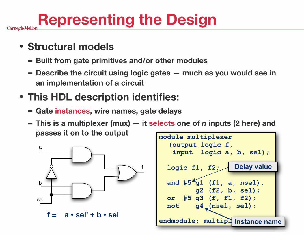
Representing the Design• Structural models
- Built from gate primitives and/or other modules
- Describe the circuit using logic gates — much as you would see in an implementation of a circuit
• This HDL description identifies: - Gate instances, wire names, gate delays
- This is a multiplexer (mux) — it selects one of n inputs (2 here) and passes it on to the output module multiplexer
(output logic f, input logic a, b, sel);
logic f1, f2;
and #5 g1 (f1, a, nsel), g2 (f2, b, sel); or #5 g3 (f, f1, f2); not g4 (nsel, sel);
endmodule: multiplexerf = a • sel' + b • sel
a
b
sel
f Delay value
Instance name

18-240 L2 —
module multiplexer (output logic f, input logic a, b, sel);
logic f1, f2;
and #5 g1 (f1, a, nsel), g2 (f2, b, sel); or #5 g3 (f, f1, f2); not g4 (nsel, sel);
endmodule: multiplexer
module multiplexer (output logic f, input logic a, b, sel);
logic f1, f2;
or #5 g1 (f, f1, f2); not g2 (nsel, sel); and #5 g3 (f1, a, nsel), g4 (f2, b, sel);
endmodule: multiplexer
Are these two modules the same?
10
a
b
sel
f
2-to-1 Mux as a 2-level SOP
f
sel
a
b
Standard symbol for 2-to-1 Mux

18-240 L2 —
or #delay instance-name (out, in1, in2, in3, …);
Representation: Gate-Level Models• Function: Gate’s basic operation
- Generally, HDLs have built-in gate-level primitives ✦ SystemVerilog has: • NAND, NOR, AND, OR, XOR, XNOR, BUF, NOT, ...
- The gates operate on input values producing an output value
• Delay: Temporal characteristics - Signal propagation time
• Typical Verilog gate instantiation is:
optional “many”
11
and #5 g1(f1, a, nsel);

18-240 L2 —
Delay of a gate • Example: AND gate
- The output follows, after the specified delay, the inputs according to the AND function
- Delay (#10 here) is the input to output (“transport”) delay
• The delay is given in a unit-less “time-base” - You can assign it to any desired time, e.g. 1psec, 100nsec, days, etc
12
10 20 30 40 50 60 70 80
A
B
Z
#10A
BZ
τ — transport delay

18-240 L2 —
• Gate models logically do the right thing - NAND anything with a 0, and you get a 1. This includes having an x
or z on the other input ✦ The nature of the NAND gate
- NAND two x’s and you get an x — unknowns beget unknowns
- z treated as an x on input - If you forget to connect an input … it will be seen as a z
- At the start of simulation, everything is an xInput B
0 1 x z0 1 1 1 11 1 0 x xx 1 x x xz 1 x x x
Four-Valued Logic
A 4-valued truth table for
a 2-input NAND gate
Inpu
t A
Again, a reasonable approximation not the absolute reality 13
A=1B=x
A=0B=x
A=z
B=z
x
1
x

18-240 L2 —
More complex circuits• For example, build a 2-bit wide 2:1 multiplexer
- Build boolean expressions from scratch as before, or......
- Put two 1-bit 2:1 muxes in the same module ✦ ... and tie the select lines together
14
a[1:0]
b[1:0]
f [1:0]
sel
2
22
a1
b1
a0
b0
f1
f0
sel

Big Idea: Instantiation• Modules and primitive gates can be instantiated —
made real / created — to many sites in a design - Previously, two ANDs, one OR, and a NOT gate were instantiated
into a module — our multiplexer
- Now we instantiate two copies of module mux into module wideMux
• NOT like subroutine calls! (looks similar, though) - This is like putting 2 of the same chips on a virtual protoboard and
connecting them
module wideMux (output logic f1, f0, input logic a1, a0, b1, b0, sel);
mux bit1 (.f(f1),.a(a1),.b(b1),.sel(sel)), bit0 (.f(f0),.a(a0),.b(b0),.sel(sel));
endmodule: wideMux
module mux (output logic f, input logic a, b, sel);
logic f1, f2;
and #5 g1 (f1, a, nsel), g2 (f2, b, sel); or #5 g3 (f, f1, f2); not g4 (nsel, sel); endmodule: mux

18-240 L2 —
Not everything is single bit• Bundles of wires often easier to manipulate
- Scalars — single bit things
- Vectors — multibit things
• wideVectorMux uses vectors - Connecting to it is easier
- Also easier to change if bit sizes vary
module wideVectorMux (output logic [1:0] f, input logic [1:0] a, b, input logic sel);
mux bit1 (.f(f[1]),.a(a[1]),.b(b[1]),.sel(sel)), bit0 (.f(f[0]),.a(a[0]),.b(b[0]),.sel(sel));
endmodule: wideVectorMux
16
t t[0]t[1]
module mux (output logic f, input logic a, b, sel);
logic f1, f2;
and #5 g1 (f1, a, nsel), g2 (f2, b, sel); or #5 g3 (f, f1, f2); not g4 (nsel, sel); endmodule: mux

18-240 L2 —
Hierarchical Design• Design hierarchy of modules is built
using instantiation - Predefined “primitive” gates (AND, OR, …)
- Simple modules are built by instantiating these gates (components like Muxes)
- Other modules are built by instantiating simple components, …
• Hierarchy controls complexity - No one designs 1B random gates — they use
hierarchy
- Analogous to the use of function abstraction in SW
• Complexity is a BIG deal - In real world how big is size of one “blob” of
random logic that we would describe as an HDL, then synthesize to gates? 17
How many?

18-240 L2 —
module mux (output logic f, input a, b, sel);
and #5 g1 (f1, a, nsel), g2 (f2, b, sel); or #5 g3 (f, f1, f2); not g4 (nsel, sel);
endmodule: mux
module mux (output logic f, input a, b, sel);
and #5 g1 (f1, a, nsel), g2 (f2, b, sel); or #5 g3 (f, f1, f2); not g4 (nsel, sel);
endmodule: mux
Instantiation and Hierarchymodule mux2wide (output logic [1:0] f, input [1:0] a, b, input sel);
mux b0 (f[0], a[0], b[0], sel), b1 (f[1], a[1], b[1], sel); endmodule: mux2wide
Namespace How many sels? Wires/nets Bit-select
What’s left?
18
b0 b1
Instantiation is structural —
connects things together,
regardless of what’s inside!
SVbook 1.3

18-240 L2 —
module mux (output logic f, input logic a, b, sel);
and #5 g1 (f1, a, nsel), g2 (f2, b, sel); or #5 g3 (f, f1, f2); not g4 (nsel, sel);
endmodule: mux
Implicit declaration of wires • How come there were no wires declared in some of
these modules? - Gate instantiations implicitly declare wires for their outputs. Gates
drive wires!
- All other connections must be explicitly declared as logic (wires) ✦ For instance, connections between module ports
module putTogether (); logic w1, w2, w3, w4;
mux bart (w1, w2, w3, w4); aaa homer (w3, w2, w1); …
f1, f2, nsel are implicitly declared logic variables
wires explicitly declared (good)
19
Hint: Add the following line to your SystemVerilog files. It flags any typos that would otherwise be implicitly declared as logic variables: `default_nettype none

18-240 L2 —
Verilog Descriptions: Top-Level View• Recall the 4 different pieces of a design
20
module top
M1 M2 M3
Integration Module (wire up low-level mods)
TestBench: Send test inputs, monitor outputs
top — encloses the whole design. You simulate this
testbench — the “initial block” that tests the design
The design — this is the stuff you
synthesize (automatically
design). Possibly many levels of hierarchy here
primitive modules — gates provided
by language

18-240 L2 —
Example of 4 Parts
module mux (output logic f, input logic a, b, sel);
logic f1, f2, n_sel;
and #2 g1(f1, a, n_sel), g2(f2, b, sel); or #2 g3(f, f1, f2); not g4(n_sel, sel); endmodule: mux
module muxTester (output logic a, b, sel, input logic muxOut);
initial begin $monitor($time,, "a = %b, b = %b, sel = %b, muxOut = %b", a, b, sel, muxOut); a = 0; b = 0; sel = 0; #10 b = 1; #10 a = 1; #10 b = 0; #10 sel = 1; . . . <lines snipped> #10 $finish; end
endmodule: muxTester
the testbench,
(no synthesis)
the design
21
module system; logic wire_a, wire_b, select, muxOut;
mux DUT (muxOut, wire_a, wire_b, select); muxTester mt (wire_a, wire_b, select, muxOut);
endmodule: system
Module muxTester generates inputs for module mux and displayed changes. Module system was the design
“top” module

18-240 L2 —
module muxTester (output logic a, b, sel, input logic muxOut);
initial begin $monitor($time,, "a = %b, b = %b, sel = %b, muxOut = %b", a, b, sel, muxOut); a = 0; b = 0; sel = 0; #10 b = 1; #10 a = 1; . . . <lines snipped> #10 $finish; end
endmodule: muxTester
Procedural Code
22
•The initial block is executed at the beginning of the simulation •Statements inside the initial block are executed in order -Unlike structural code, which is describing hardware
-Specify a sequence, or “procedure”
• Beware of designs using multiple initial blocks, as the order in which they execute is not deterministic

18-240 L2 —
module muxTester (output logic a, b, sel, input logic muxOut);
initial begin $monitor($time,, "a = %b, b = %b, sel = %b, muxOut = %b", a, b, sel, muxOut); a = 0; b = 0; sel = 0; #10 b = 1; #10 a = 1; #10 b = 0; #10 sel = 1; #10 b = 1; #10 a = 0; #10 b = 0; #10 $finish; end
endmodule: muxTester
Behavior of initial block
a
b
23
• $monitor prints its string when executed
• Prints the string any time one of the listed values changes
• Prints at end of current simulation time (all changes have occurred)
10 20 30 40 50 60 70 80
sel

18-240 L2 —
module muxTester (output logic a, b, sel, input logic muxOut);
initial begin $monitor($time,, "a = %b, b = %b, sel = %b, muxOut = %b", a, b, sel, muxOut); a = 0; b = 0; sel = 0; #10 b = 1; #10 a = 1; #10 b = 0; #10 sel = 1; #10 b = 1; #10 a = 0; #10 b = 0; #10 $finish; end
endmodule: muxTester
So, what happens here?
a
b
24
• a, b, sel set to 0 at time 0 • $monitor prints
• initial block suspends for 10 time units (#10)
• a, b, sel propagate through AND, OR, NOT gates
• mux output changes 4 time units later • At time 4, $monitor prints
• b input changes at time 10 • …
10 20 30 40 50 60 70 80
sel
module mux (output logic f, input logic a, b, sel);
and #2 g1(f1, a, n_sel), g2(f2, b, sel); or #2 g3(f, f1, f2); not g4(n_sel, sel);
endmodule: mux

18-240 L2 —
Another version of muxTester• Other procedural
statements - You can use “for,” “while,”
“if-then-else” and others
- This makes it easier to write if you have lots of input bits
- All four values of 3 bits are presented to mux
25
test test[0] -- atest[1] -- b
module muxTester; // no ports! logic [2:0] test; logic muxOut;
mux (muxOut, test[0], test[1], test[2]);
initial begin $monitor ($time, " test=%b, muxOut=%b", test, muxOut); for (test = 0; test < 7; test++) #10; #10 $finish; end
endmodule: muxTester
module mux (output logic f, input logic a, b, sel);
and #2 g1(f1, a, n_sel), g2(f2, b, sel); or #2 g3(f, f1, f2); not g4(n_sel, sel);
endmodule: mux
test[2] -- sel

18-240 L2 —
Step through the for loop• At time 0
- test = 0 = 000 - test[0] is a zero, goes to mux’s a
input. test[1] to b, test[2] to sel - while waiting for #10, values
propagate to muxOut - after #4 monitor prints
• …time 10 - test = 1 = 001 - while waiting for #10, ditto
• …time 20 - test = 2 - while waiting for #10, ditto
• … • …time 70
- test = 7 = 111, loop exits - while waiting for #10, monitor
prints, $finish 26
module muxTester; // no ports! logic [2:0] test; logic muxOut;
mux (muxOut, test[0], test[1], test[2]);
initial begin $monitor ($time, " test=%b, muxOut=%b", test, muxOut); for (test = 0; test < 7; test++) #10; #10 $finish; end
endmodule: muxTester

• Three different ways to list signals into a module
mux DUT (.a(wire_a), .f(muxOut), .b(wire_b), .sel(select));
Specifying Port Connections
module system; logic wire_a, wire_b, select, muxOut;
mux DUT (muxOut, wire_a, wire_b, select); muxTester mt (wire_a, wire_b, select, muxOut);
endmodule: system
internal name (with the dot)
external name (i.e. signal in muxTester)
Named port: signals are matched based on the names given
Ordered port: signals are matched based on the order that they are listed
module mux (output logic f, input logic a, b, sel);
module system; logic a, b, sel, f;
mux DUT (.*); muxTester mt (.*);
endmodule: system
Named port shortcut: works whenever all internal names match external names

18-240 L2 —
Other non-HW things you can do• Useful user-interface mechanisms
- $monitor — give it a list of variables. When one of them changes, it prints the information. Can only have one of these active at a time
✦ prints something like: 4 a=0, b=0, sel=0, muxOut=0<return>
- $display() — sort of like printf() in C ✦ $display ("Hello, world — %h", hexvalue)
extra space %b is binary (also, %h, %d and others)
newline automatically
included
display contents of data item called “hexvalue” using hex digits (0-9,A-F)
What if what you print has the value x or z?
28
use "straight" quotes in all cases
$monitor ($time, " a=%b, b=%b, sel=%b, muxOut=%b",a, b, sel, muxOut);

18-240 L2 —
Concurrent Activity• The point is
- In the real implementation ➙ all activity will be concurrent
- Thus the simulator models the elements of the system as being concurrent in simulated time ✦ The simulator stands on its head trying to do this!
• Thus, - Even though the simulator executes each element of the design one
at a time …
- … it will try to make this transparent to you
- … we’ll call it concurrent
29

18-240 L2 —
SystemVerilog Summary • Our view of SystemVerilog so far is
- We describe our design in a module, possibly with some instantiated modules and gate primitives
- We describe a test module for our design to generate inputs for our design
- Connect the two together and simulate them ✦ If it doesn’t work, try again
- When it works, synthesize and download configuration to FPGA
30

18-240 L2 —
New idea: Continuous assign
• Let me write what I’m really thinking
- Then let the tools figure out the minimization and gate mapping
- Less typing and easier to understand • How do you think about the assign statement?
- When one of the variables on the right-hand side changes, the output (left-hand side) is re-evaluated, updated, and propagated to its fanout
- It’s like your own special gate with the functionality specified31
module stuff (output logic p, input logic a, b, c);
assign p = (a & b) | (~b & c) | (~a & ~b & ~c);
endmodule: stuff
18-240 L2 —
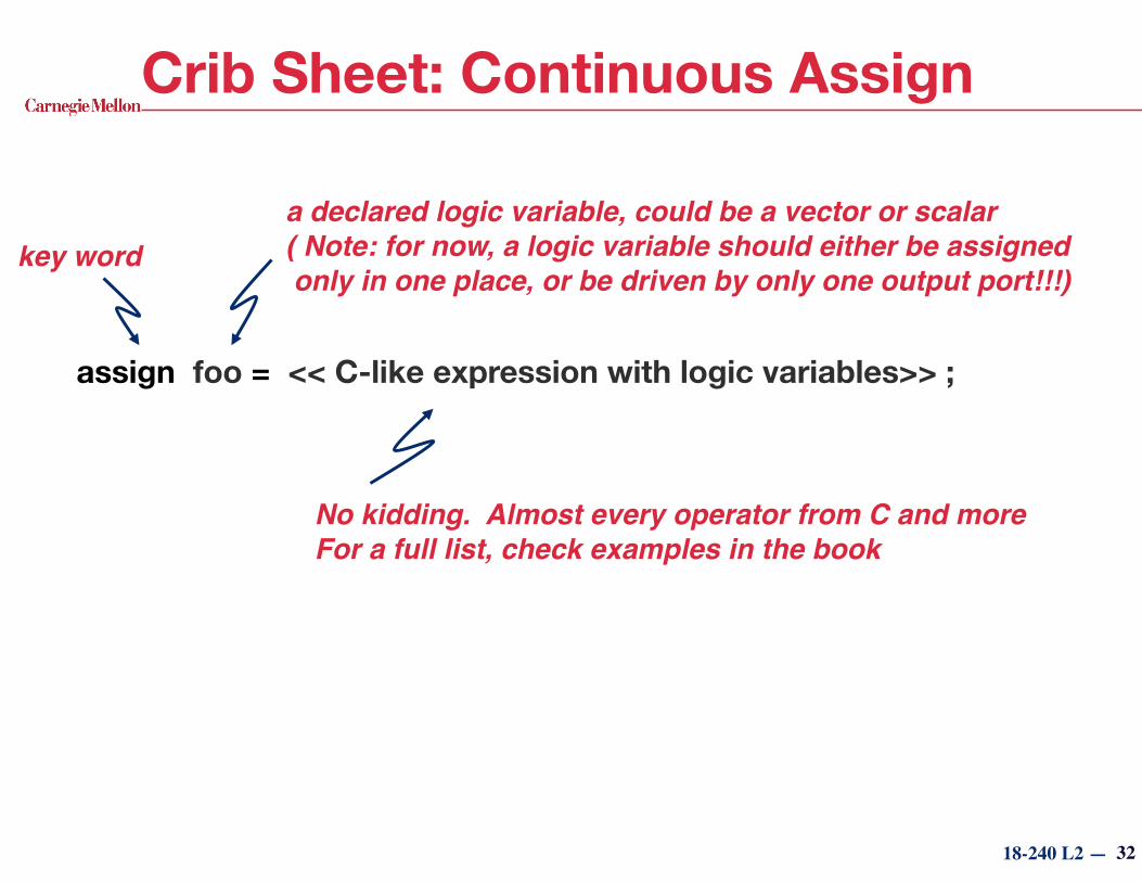
Crib Sheet: Continuous Assign
assign foo = << C-like expression with logic variables>> ;
a declared logic variable, could be a vector or scalar( Note: for now, a logic variable should either be assigned only in one place, or be driven by only one output port!!!)
key word
No kidding. Almost every operator from C and more For a full list, check examples in the book
32

18-240 L5 —
Procedural Descriptions?
char mux(char sel, char b, char c) {
char f; if (sel==1) f=b; else f=c; return f;
}
Is this a combinational function??
It’s a stateless function — no memory
In other words, can you rewrite it in a truth table? How about a boolean expression? NAND gates?
Yes, it is combinational
Output depends solely on the inputs
Well defined input to output mapping independent of history
33
Think about a C function that selects a parameter and returns it
Fine, but what has this got to do with building real hardware?
A C fu
nction
18-240 L2 —
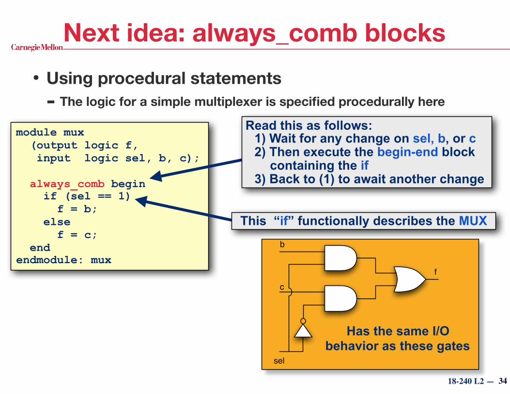
Next idea: always_comb blocks• Using procedural statements
- The logic for a simple multiplexer is specified procedurally here
module mux (output logic f, input logic sel, b, c); always_comb begin if (sel == 1) f = b; else f = c; end endmodule: mux
Has the same I/O behavior as these gates
34
Read this as follows: 1) Wait for any change on sel, b, or c 2) Then execute the begin-end block
containing the if 3) Back to (1) to await another change
This “if” functionally describes the MUX
sel
b
c
f

18-240 L2 —
always_comb blocks• always_comb blocks
- Can think of them as your own special gate (combinational function)
- Has inputs and outputsmodule mux (output logic f, input logic sel, b, c); always_comb begin if (sel == 1) f = b; else f = c; end endmodule: mux
35
In contrast to the previous C example, you don’t have to “call” the always_comb block.
Rather, when its “inputs” change — the output is recalculated as specified. Hmm, much like the real hardware on the right!
Has the same I/O behavior as these gates
sel
b
c
f

18-240 L2 —
To “always” or to “assign” …?• For 2:1 MUX action, do you write
• These are the same — Use whatever is easier and less likely to get wrong
• Typically - assign — use this for simple one-line statements
- always_comb — use this for more complex logic
logic sel, a, b, f; assign f = (sel) ? a : b;
logic sel, a, b, f; always_comb begin if (sel) f = a; else f = b; end
or
36
logic sel, a, b, f; always_comb f = (sel) ? a : b;
Could also write:

18-240 L2 —
Now, the more powerful picture• Can we leave Kmaps behind?
- Yes! Though still helpful at times
• The blob-o-logic view
37
…
Combinational Logic
…Combinational
Logic
… …
Combinational Logic
…
assign val = (a^b)&c;
always_comb f = sel ? b : c;
…
always_comb begin blah blah blah lots of inputs and outputs, complex stuff, blah blah
end
Synthesis Tech mapping, Place & Route
We’re not designing with gates in mind, but with blobs of combinational logic!
assign and always_comb are the basis for describing these
Tools finish the job

18-240 L5 —
module mux (output logic f, input logic sel, b, c); always_comb begin if (sel == 1) f = b; else f = c; end
endmodule: mux
Is anything you write combinational?• No! There are some restrictions and limitations • A control path of a block — a sequence of
operations performed when executing the block - There may be many data-dependent paths!!
• Combinational output of a block — a variable (or variables) assigned to in every control path
For our mux block:Control path:
Combinational output:
38
f
through “then” part of if statement
through “else” part of if statement

18-240 L2 —
module mux (output logic f, input sel, b, c); always_comb
if (sel == 1) f = b; else f = c; endmodule: mux
Rules for Writing Combinational Logic• It all boils down to writing a stateless function • The rules for modeling combinational logic using procedural
statements 1. A change on any input of the function will cause it to execute 2. The combinational output(s) must be assigned in any execution (thus in every
control path) 3. Nothing is remembered from execution to execution
Issue 3, (another way of stating issue 2) the loop is stateless. Nothing remembered internally. Handled by you!
Issue 1, handled by always_comb or assign
Issue 2, handled by you!c
b
sel
f
39virtual module — a blob of combinational logic SVbook 2.1.2
18-240 L5 —
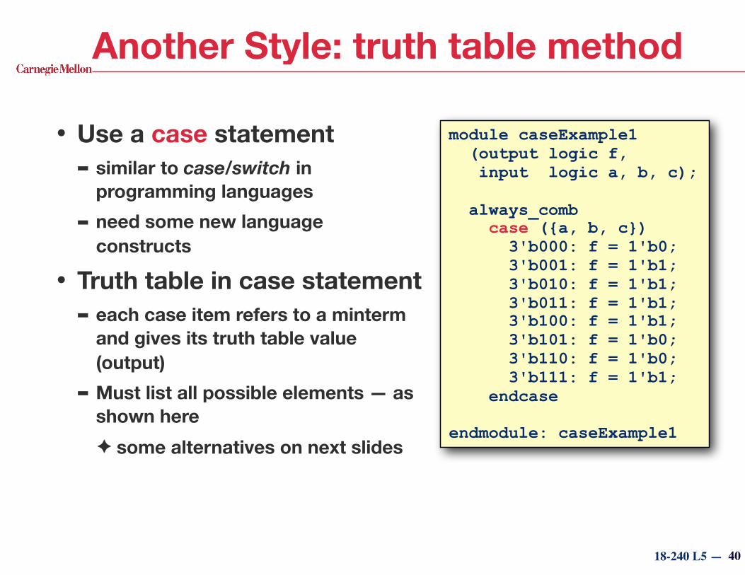
Another Style: truth table method
• Use a case statement - similar to case/switch in
programming languages
- need some new language constructs
• Truth table in case statement - each case item refers to a minterm
and gives its truth table value (output)
- Must list all possible elements — as shown here ✦ some alternatives on next slides
module caseExample1 (output logic f, input logic a, b, c);
always_comb case ({a, b, c}) 3'b000: f = 1'b0; 3'b001: f = 1'b1; 3'b010: f = 1'b1; 3'b011: f = 1'b1; 3'b100: f = 1'b1; 3'b101: f = 1'b0; 3'b110: f = 1'b0; 3'b111: f = 1'b1; endcase
endmodule: caseExample1
40

18-240 L5 —
module caseExample1 (output logic f, input logic a, b, c);
always_comb case ({a, b, c}) 3'b000: f = 1'b0; 3'b001: f = 1'b1; 3'b010: f = 1'b1; 3'b011: f = 1'b1; 3'b100: f = 1'b1; 3'b101: f = 1'b0; 3'b110: f = 1'b0; 3'b111: f = 1'b1; endcase
endmodule: caseExample1
Truth table method, continued• Sized Constants
q = 4'b0111; s = 2'bzx r = 8'b111x0001
size in bits value in 4-value logic
r = 8'b111x_0001
• Concatenation {a, b, c} concatenates a, b, and c into a single vector
Example: {q, r, s} ➙ 14'b0111_111x0001_zx
41
visual spacer
base of constant (b, d, h)
Must be straight quote
constants

18-240 L5 —
Ex: 2 complex alternate descriptions
• Driving the e segment of a 7-segment display - On if the 4-bit num to display is:
0, 2, 6, 8, a, b, c, d, e, f
module e_segment (output logic e, input logic [3:0] bin_value);
assign e = (((bin_value < 10) && (bin_value&1)) || (bin_value==4)) ? 0:1;
endmodule: e_segment
module e_segment (output e, input [3:0] bin_value);
always_comb case (bin_value) 4'd1: e = 0; 4'd3: e = 0; 4'd4: e = 0; 4'd5: e = 0; 4'd7: e = 0; 4'd9: e = 0; default: e = 1; endcase
endmodule: e_segment
42
f
e
g
a
d
c
b
p

18-240 L5 —
An example with a don’t care• Rules
- To specify a don’t care, put “x” on the right-hand side of an assignment
f = 1'bx; - BTW, you can’t say
“if (a == 1'bx)…” — this has meaning in simulation, but not in synthesis
module caseExample2 (output logic f, input logic a, b, c);
always_comb case ({a, b, c}) 3'b001: f = 1'b1; 3'b010: f = 1'b1; 3'b011: f = 1'b1; 3'b100: f = 1'b1; 3'b111: f = 1'b1; 3'b110: f = 1'b0; default: f = 1'bx; endcase
endmodule: caseExample2
Synthesis tools interpret this as “don’t care”
43
BC00 01 11 10A
0 X 1 1 11 1 X 1 0

18-240 L5 —
BC00 01 11 10A
0 X 1 1 11 1 X 1 0
Don’t care with unique case• Rules
- unique case says “one and only one” of the items will match
- All others are don’t cares for synthesis
- In simulation, an error will occur (stopping the sim) if one of the don’t care conditions appear
module caseExample3 (output logic f, input logic a, b, c); always_comb unique case ({a, b, c}) 3'b001: f = 1'b1; 3'b010: f = 1'b1; 3'b011: f = 1'b1; 3'b100: f = 1'b1; 3'b111: f = 1'b1; 3'b110: f = 1'b0; endcase
endmodule: caseExample3
44

18-240 L5 —
output logic [1:0] newJ; output logic out; input logic i, input logic [1:0] j;
always_comb case (j) 2'b00: begin newJ = (i == 0) ? 2'b00 : 2'b01; out = 0; end 2'b01: begin newJ = (i == 0) ? 2'b10 : 2'b01; out = 1; end 2'b10: begin newJ = 2'b00; out = 0; end default: begin newJ = 2'b00; out = 1'bx; end endcase
Cases can be individually complex…
Three input bits, Three output bits
45

18-240 L5 —
Synthesizable “Style”: This is OK • This is an okay approach to write descriptions for
combinational logic that will be synthesized
module xyzzy (ports); … always_comb begin q = b1 … b2 … b3 r = b1 … b2 … b3 end
always_comb begin s = yadda yadda yadda end … endmodule: xyzzy
If the functions share common inputs, you can use one always_comb block
If they don’t, use one always_comb per function 46
Multiple always_comb
blocks in a module
All always_comb blocks within a module will be
optimized together
Multiple functions of the same inputs in one always block

18-240 L5 —
Synthesizable “Style”: Not OK• Don’t try this at home
module xyzzy (ports); … always_comb begin f = yadda; end
always_comb begin f = yadda yadda; end
endmodule: xyzzy
What is the value of f if both always_comb blocks execute at the same time?You don’t know. The always_comb blocks execute in arbitrary order
What if f depends on different variables in the two blocks?It won’t be combinational
The 3rd Golden Rule: A combinational
variable is assigned a value in no more than
one always block
47
Nope!

18-240 L5 —
Example: Day of Year Calculator• Problem statement
- Given the month and the day of the month, what is the day’s number in the year?
- e.g., February 5 would be the 36th day of the year (31 + 5) - Ignore leap years for now
• If you were in software land (“lala land”)… - In C, you might write
- But, duh, we’re not writing software, so how do we go about calculating the day of the year in hardware?
48
int dayOfYear (int dayOfMonth, int month) {
return (dayOfMonth + monthOffset(month)); }

18-240 L5 —
monthOffset
Example: Day of Year Calculator• In hardware:
- Nothing get’s “called” (no functions!)
- Rather, we think of patches of silicon with logic gates and transistors
- These patches implement logic functions
- When one (or more) of their inputs changes, the output(s) might change
- It all happens because of voltages, currents, and wired connections
• Let’s draw a picture (right) - There’s a module that calculates
something
- It has ports with names
- What has to happen inside?
49
+
Combinational Logic
dayOfMonth month
dayOfYear

18-240 L5 —
module dayOfYrCalc (input logic [4:0] dayOfMonth, input logic [3:0] month, output logic [8:0] dayOfYear);
logic [8:0] monthOffset;
assign dayOfYear = dayOfMonth + monthOffset;
always_comb unique case (month)
4'd1: monthOffset = 0; // January 4'd2: monthOffset = 31; // February 4'd3: monthOffset = 59; // March … 4'd12: monthOffset = 334; // December
endcase
endmodule: dayOfYrCalc
Now, some code
50
+
Combinational Logic
dayOfMonth month
dayOfYear
monthOffset
18-240 L5 —
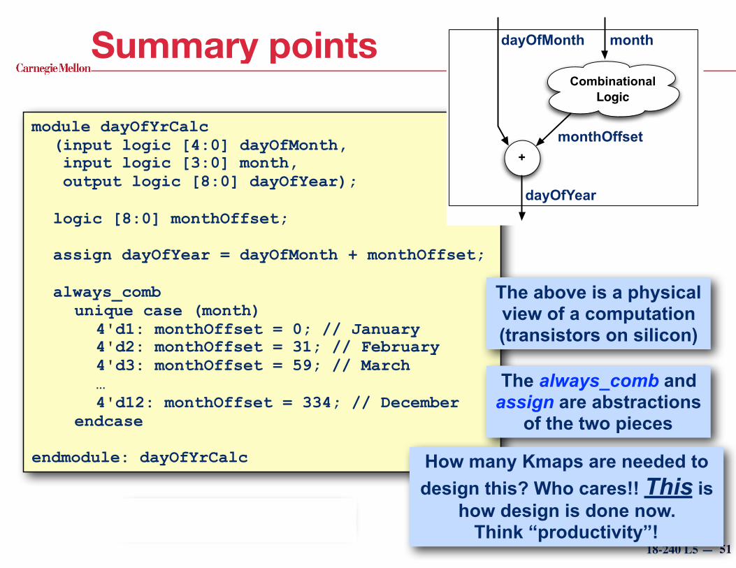
Summary points
51
module dayOfYrCalc (input logic [4:0] dayOfMonth, input logic [3:0] month, output logic [8:0] dayOfYear);
logic [8:0] monthOffset;
assign dayOfYear = dayOfMonth + monthOffset;
always_comb unique case (month)
4'd1: monthOffset = 0; // January 4'd2: monthOffset = 31; // February 4'd3: monthOffset = 59; // March … 4'd12: monthOffset = 334; // December
endcase
endmodule: dayOfYrCalc
+
Combinational Logic
dayOfMonth month
dayOfYear
monthOffset
The above is a physical view of a computation (transistors on silicon)
The always_comb and assign are abstractions
of the two pieces
How many Kmaps are needed to design this? Who cares!! This is
how design is done now. Think “productivity”!
This isn’t software!

18-240 L5 —
Leap years?
52
module dayOfYrCalc (input logic [4:0] dayOfMonth, input logic [3:0] month, input logic leapYear, output logic [8:0] dayOfYear);
logic [8:0] monthOffset;
assign dayOfYear = dayOfMonth + monthOffset;
always_comb begin unique case (month)
4'd1: monthOffset = 0; // January 4'd2: monthOffset = 31; // February 4'd3: monthOffset = 59; // March … 4'd12: monthOffset = 334; // December
endcase monthOffset = monthOffset + ((month > 2) && leapYear) ? 1 : 0;
end
endmodule: dayOfYrCalc
Or you could have a year input to the module (e.g., 2015) and
specify some combinational logic to determine if it’s a leap year.
Add a leap year input
Include it in the calculation

18-240 L5 —
Crib sheet: always_comb
f = .....f = .....
always_comb begin
end
implicitly lists every variable that is “read” in the block
- f is the combinational output; all dependent variables are inputs - A truth table can be built by evaluating the final value of f under every input combination
f = .....f = .....
the body is a C-like procedural block that writes to the output variable(s) (f in this example)
Almost anything goes but the final value of f must be statically evaluatable for every possible input
f must be written to at least once in every possible control path (begin-to-end)
f can be written to multiple times (the last one is remembered when the process reaches the end)
f can depend on f, but must be written to first, before you try to use it (otherwise implies memory)
f cannot be written to in any other process block
53

18-240 L5 —
Statement Looks like Starts How it works Use in Synthesis?
initialinitial begin
...blah blah
endStarts when simulation starts ... in arbitrary
order
Execute once and stop
No, used as testbench
always_combalways_comb begin
...blah blah
end
Execute once per trigger
Yes, to synthesize
combinational circuits
Aside: About Verilog Processes• Procedural descriptions are introduced by
initial and always_comb statements (and others)
• Points: - They all execute concurrently (i.e., they are processes, threads) - They contain procedural statements like if-then-else, case, loops,
functions, …54

18-240 L5 —
Behavioral Modeling of (Comb. Logic)
• Procedural statements - Defines combinational input/output relationship procedurally
✦ imagine a small program to compute what should be the output for any given input
- Statements using “always_comb” SystemVerilog construct
• Normally don’t think of C procedural stuff as “logic” - They look like C: mix of ifs, case statements, assignments …
- … but a semantic interpretation we put on them allows them to be used for simulation & synthesis (giving equivalent results)
• Current technology - You can do combinational (and later, sequential) design
- Sizable designs can take hours … overnight … to run
- Companies pay $50K - 80K per copy for such software ✦ These aren’t cellphone apps!
- The software we use is more like $5K55

18-240 L5 —
Summary• New design methodology
- Hardware description language ➙ synthesis ➙ place and route ➙ FPGA implementation
- This is the prevalent mode of hardware design today
• Synthesizable Verilog - Behavioral constructs and basic rules covered
- You are restricted in what you can write and how you write it Somewhat arbitrarily by what synthesis tools can recognize
- There are many more legal alternatives than what we showed you
- Until you know better (e.g., by reading the documentation), please don’t go invent something we didn’t show you
• This isn’t writing software - What you write and how you write it will have a great effect on the
results (good hw, bad hw, wrong hw, or even “not hw”)
- You’re describing Boolean functions and their interconnections56

18-240 L2 —
Today's Exercise• Purpose: Get in lab, get familiar with the tools • Vivado
- Software used to execute FPGA design flow on Xilinx devices ✦ We will be using ZedBoard and Nexys4 boards
• Exercise - Hasn't been tuned to JRI lab setup, so bear with me
- Connect switches to LEDs using Zynq FPGA
57