systems support for manipulating large scientific datasets
DESCRIPTION
Systems Support for Manipulating Large Scientific Datasets. Research/Development Group Tahsin Kurc Umit Catalyurek Renato Ferreira Matthew Spencer Mike Gray. Joel Saltz Biomedical Informatics Department The Ohio State University. Active Data Repository (ADR). - PowerPoint PPT PresentationTRANSCRIPT
Systems Support for Manipulating Large Scientific Datasets
Joel SaltzBiomedical Informatics Department
The Ohio State University
Research/Development Group Tahsin Kurc
Umit Catalyurek Renato Ferreira
Matthew Spencer Mike Gray

2
Active Data Repository (ADR)
• A C++ class library and runtime system• targets storage, retrieval and manipulation of multi-dimensional
datasets on parallel machines.
• Several services are customizable for various application specific processing.
• Runtime system support for common operations • data retrieval, memory management, and scheduling of
processing across a parallel machine.
• Data declustering/clustering, Indexing• Buffer management and scheduling of operations• Efficient execution of queries on a parallel
machine

3
Some ADR applications
Processing Remotely-Sensed Data
NOAATiros-Nw/ AVHRR sensor
AVHRR Level 1 DataAVHRR Level 1 Data•As the TIROS-N satellite orbits, the Advanced Very High Resolution Radiometer (AVHRR)sensor scans perpendicular to the satellite’s track.•At regular intervals along a scan line measurementsare gathered to form an instantaneous field of view(IFOV).•Scan lines are aggregated into Level 1 data sets.
A single file of Global Area Coverage(GAC) data represents:•~one full earth orbit.•~110 minutes.•~40 megabytes.•~15,000 scan lines.
One scan line is 409IFOV’s
Visualization
Pathology
Earth Systems Science
Satellite Data

4
ADR Applications
• Titan• a parallel database server for remotely sensed
satellite data
• Virtual Microscope• a data server for digitized microscopy images• browsing, and visualization of images at different
magnifications
• Bays and Estuaries Simulation System• Water contamination studies• Hydrodynamics simulator is coupled to chemical
transport simulator

5
ADR Applications (cont’d)
• VOL-Vis• a visualization system for ray-casting based
volume rendering of out-of-core astronomy datasets
• uses MPIRE (from SDSC) functions for rendering operations.
• TM-Vis• a dataset server for browsing and visualizing
Landsat Thematic Mapper scenes
• ISO-Vis• iso-surface rendering of very large 3D datasets
from subsurface reactive transport simulations

6
Data Processing Loop
reductionfunction
source data elements
result data elements
intermediatedata elements(accumulatorelements)

7
Data Processing Loop
DU = Select(Output, R); DI = Select(Input, R);
for (ue in DU)
{ read ue; ae = Initialize(ue); A = ae; }
for (ie in DI)
{ read ie; SA = Map(ie, A);
for (ae in SA) { ae = Aggregate(ie,ae); }}
for (ae in A)
{ ue = Finalize(ae); write ue; }Output HandlingPhase
InitializationPhase
accumulator
Reduction Phase
defined by some spatial relationship
• could be expensive• order independent

8
ADR System Architecture
• Front-end: the interface between clients and back-end. Provides support for clients:• to connect to ADR,• to query ADR to get information about already registered
datasets and user-defined methods,• to create ADR queries and submit them.
• Back-end: data storage, retrieval, and processing.• Distributed memory parallel machine or cluster of
workstations, with multiple disks attached to each node• Customizable services for application-specific processing• Internal services for data retrieval, resource management

9
ADR ARCHITECTURE
ADR Back End
Dataset Service
Attribute SpaceService
Data AggregationService
IndexingService
Query ExecutionService
Query PlanningService
Query InterfaceService
Query SubmissionService
Front End
Application Front End
Client
ClientRequest
Store Input Datain ADR
Output
Customizable ADRServices Customized using application specific functions

10
ADR Internal Services
• Query interface service• receives queries from clients and validates a query
• Query submission service• forwards validated queries to back end
• Query planning service• determines a query plan to efficiently execute a set of
queries based on available system resources
• Query execution service• manages system resources and executes the query plan
generated.
• Handling Output• Write to disk, or send to the client using Unix sockets, or
Meta-Chaos (for parallel clients).

11
ADR Customizable Services
• Developed as a set of modular services in C++• customization via inheritance and virtual functions
• Attribute space service• manages registration and use of multi-dimensional attribute
spaces, and mapping functions
• Dataset service• manages datasets loaded into ADR and user-defined
functions that iterate through data items
• Indexing service• manages various indices for datasets loaded into ADR
• Data aggregation service• manages user-defined functions to be used in aggregation
operations

12
Developing An Application with ADR
• Loading and Registering Datasets into ADR
• Customizing the Front-end• Customizing the Back-end• Developing the Client

13
Datasets in ADR
• ADR expects the input datasets to be partitioned into data chunks.
• A data chunk, unit of I/O and communication, • contains a subset of input data values (and
associated points in input space)• is associated with a minimum bounding rectangle,
which covers all the points in the chunk.
• Data chunks are distributed across all the disks in the system.
• An index has to be built on minimum bounding rectangles of chunks

14
Disk Farm
Loading Datasets into ADR
• Partition dataset into data chunks -- each chunk contains a set of data elements
• Each chunk is associated with a bounding box
• ADR Data Loading Service • Distributes chunks across the
disks in the system• Constructs an R-tree index
using bounding boxes of the data chunks

15
ADR Front-end
• Interacts with application clients and the ADR back-end• Receives requests from clients and submit queries
to ADR back-end
• Provides services for clients• to connect to ADR front-end• to query ADR for information on datasets and user-
defined methods in ADR• to create and submit ADR queries

16
ADR – Back-end Customization
• Indexing Service: • Index lookup functions that return data chunks given a range
query. • ADR provides an R-tree index as default.
• Dataset Service: • Iterator functions that return input elements (data value and
associated point in input space) from a retrieved data chunk• Attribute Space Service:
• Projection functions that map a point in input space to a region in output space
• Data Aggregation Service:• Accumulator functions to create and tile the accumulator to
hold intermediate results• Aggregation functions to aggregate input elements that map
to the same output element.• Output functions to generate output from intermediate
results.

17
Data Aggregation Service• Provides interface
• to create and manipulate user-defined accumulator objects, • to implement aggregation operations,• to create output data structures, • to implement functions to convert accumulator values to the
final output values.
#include <t2_aggr.h>class T2_AggregateFuncObj {
// Initialize accumulator elementsaifElem();aifAcc();// aggregate input elements with accumulator elementsdafElem();dafAcc();
}
T2_AggregateFuncConstructor userAggregateFunc(…);

18
Client
Output HandlingPhase
Local Reduction PhaseInitialization Phase
Global Combine PhaseBack-end processor
ADR Back-end Processing

19
Application Examples
20
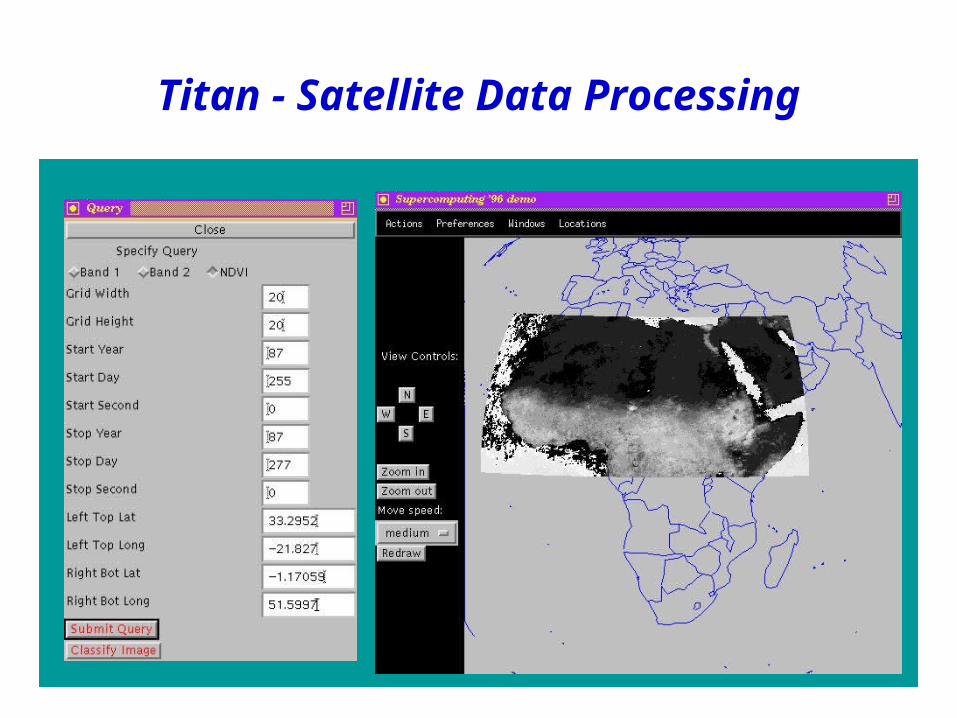
Titan - Satellite Data Processing

21
Attribute Space Service
Data Aggregation
Service
Indexing Service
Dataset Service
* Register attribute spaces - lat/lon/time, Goodes projection, etc.* Register mapping functions between attribute spaces
* Partition IFOVs into data chunks* Register iterator functions to return IFOVs from chunks
* Build an R-tree to index the IFOV chunks* Use lat/lon/time of IFOV chunks as bounding rectangles
* Register functions to: - Initialize the output image - Compute vegetation index of an output pixel with a given IFOV - Select clearest vegetation index out of a set of IFOVs
Example: Satellite Data Processing

22
FLOW CODE
CHEMICAL TRANSPORT CODE
Simulation Time
POST-PROCESSING(Time averaging, projection)
Hydrodynamics output (velocity,elevation)on unstructured grid
Grid used by chemicaltransport code
(Parallel Program)
(Parallel Program)
* Locally conservative projection* Management of large amounts of data
Visualization
Bays and Estuaries Simulation System

23ADR Back EndDataset Service
Attribute SpaceService
Data AggregationService
IndexingService
Query ExecutionService
Query PlanningService
Query InterfaceService
Query SubmissionService
Front End
Application Front End
Chemical Transport Code(UT-TRANS)
Projection Code(UT-PROJ)
Hydrodynamics Flow Code(PADCIRC)
Time steps
Visualization
* Chemical Transport Grid* Flux values on the faces
Hydrodynamics output (velocity, elevation)on unstructured grid
Query:* Time period* Number of steps* Input grid* Post-processing function (Time Averaging)
* Time averaged velocity and elevation values at grid points* Results returned using Meta-Chaos

24
FLOW CODE Partition
into chunks
POST-PROCESSING (Time averaging)
Register
TRANSPORT CODE
Attributespaces of simulators,mapping function
Chunks loaded todisks
Index created
Dataset Service
Attribute SpaceService
Data AggregationService
IndexingService
Bays and Estuaries Simulation System (Data Loading/Customization)
25
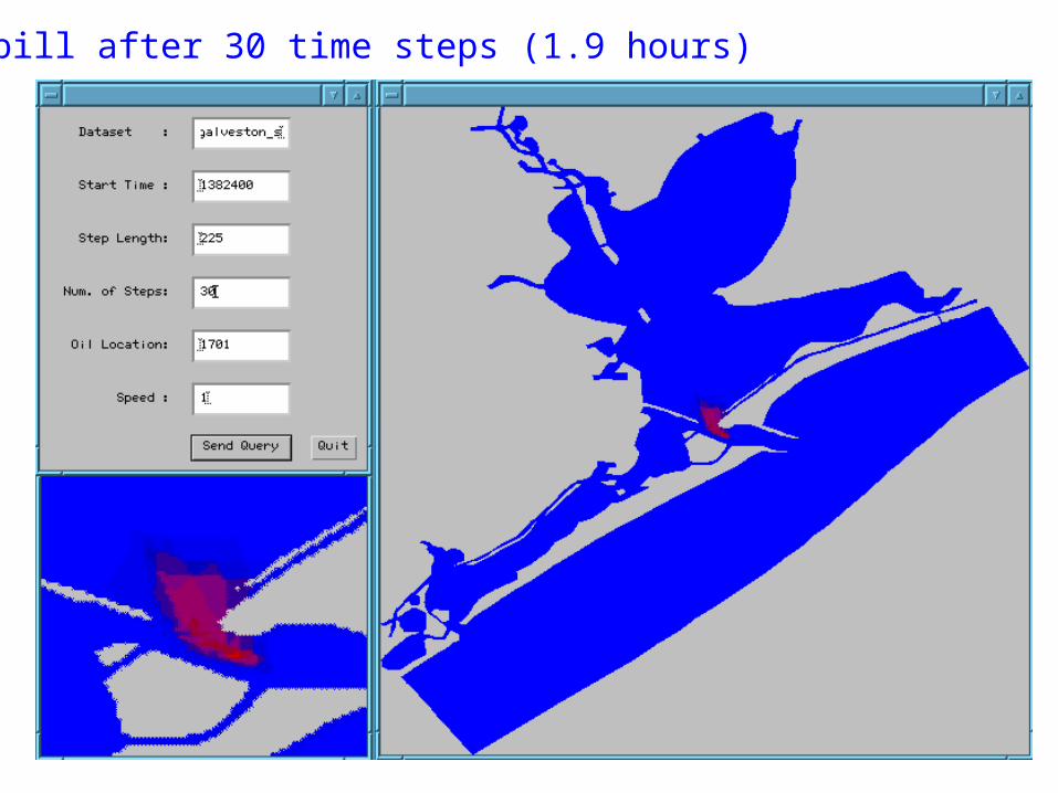
Oil spill after 30 time steps (1.9 hours)

26
ParSSim/Meta-Chaos/ADR(SC2000 Demo)
Flow SimulationReactive Transport
Simulation
Meta-Chaos
Large-scale Machine(Blue Horizon)
Cluster of PCs, Workstations
WAN
ADR
Visualization Output from reactive transport is stored/post-processed using ADR
Over LANor on
Same MachineMeta-Chaos

27
Visualization with ADR
ADR Back End
Dataset Service
Attribute SpaceService
Data AggregationService
IndexingService
Query ExecutionService
Query PlanningService
Query InterfaceService
Query SubmissionService
Front End
Application Front End
Visualization ClientQuery:* Grid id, time steps* iso-surface value* Viewing parameters
Store 3D Volumein ADR
2D image
Customizable ADRServices
Customized using VTK toolkit iso-surface rendering functions

28
Iso-surface rendering of output (e.g., speciesconcentrations) from ParSSim simulations
Visualization with ADR

29
Query InterfaceService
Query SubmissionService
Front-end
Virtual Microscope Front-end
Dataset Service
Attribute SpaceService
Data AggregationService
IndexingService
Query ExecutionService
Query PlanningService
Back-end
Client
Client Client Client
. . .
Query:* Slide number* Focal plane* Magnification* Region of interest
Image blocks
Virtual Microscope

30
Virtual Microscope Client

31
VOL-Vis (MPIRE/ADR Visualization)
• A visualization system for ray-casting based volume rendering of out-of-core astronomy datasets• uses MPIRE (from SDSC) functions for rendering operations.
• Entire volume is partitioned into slabs.• Each slab is further partitioned into sub-
volumes. Sub-volumes are distributed across disks attached to each processor.
• Rendering of slabs and composition of partial images are pipelined• ADR renders a slab at a time, creating a partial image.• Client merges partial images received from ADR.

32
ADR Back End
Dataset Service
Attribute SpaceService
Data AggregationService
IndexingService
Query ExecutionService
Query PlanningService
Query InterfaceService
Query SubmissionService
Front End
Application Front End
Visualization ClientQuery:* Grid id* 3D Window* Viewing parameters
Store 3D Volumein ADR
2D image
Customizable ADRServices
Customized using MPIRE in-core ray-casting based rendering functions
VOL-Vis

33
Current slab rendered in ADR
Partial image generated from rendered slabs
Final image
VOL-Vis

DataCutter Middleware Framework

35
A Motivating ScenarioApplication :
// process relevant raw readings// generate 3D view// compute features of 3D view// find similar features in reference db// display new view and similar cases
Extract ref
Extract raw
3D reconstruction
View result
Raw Dataset
Reference DB
WAN
Raw Datasetsensor readings
Sensor
Extract raw
Client PC
View result
Reference DBfeature list
Computation Farm
3D reconstruction3D reconstruction3D reconstruction3D reconstruction
Data Server
Extract refExtract ref

36
DataCutter
• A Component-based framework for manipulating multi-dimensional datasets in a distributed environment (the Grid) • Indexing Service: Multilevel hierarchical indexes based on R-
tree indexing method.• Filtering Service: Distributed C++ component framework
• Application processing is implemented as a set of interacting components (filters).• filters – logical unit of user-defined computation• streams - how filters communicate
• Evaluation of component-based models for data-intensive applications
• Scheduling of data flow, placement decisions

37
Filter-Stream Programming (FSP)
Purpose: Specialized components for processing data
• based on Active Disks research [Acharya, Uysal, Saltz: ASPLOS’98], dataflow, functional parallelism, message passing.
• filters – logical unit of computation• high level tasks• init,process,finalize interface
• streams – how filters communicate• unidirectional buffer pipes• uses fixed size buffers (min, good)
• manually specify filter connectivityand filter-level characteristics

38
class MyFilter : public AS_Filter_Base {public:
int init(int argc, char *argv[ ]) { … };
int process(stream_t st) { … };int finalize(void) { … };
}
Software Infrastructure
• Prototype implementation of filter framework• C++ language binding• manual placement• wide-area execution service• one thread for each instantiated filter

39
Example Applications
zoom viewread data decompress clip
•Virtual Microscope
readdataset
isosurfaceextraction
shade +rasterize
merge/ view
R E Ra M
•Iso-surface Rendering

40
[filter.A]outs = stream1 stream3[filter.B]ins = stream1outs = stream2[filter.C]ins = stream2 stream3
A
B
Cstream3
stream1 stream2
[placement]A = host1.cs.umd.eduB = host2.cs.umd.eduC = host3.cs.umd.edu
Filter Connectivity / Placement

41
host1.cs.umd.edu
AppExec Daemon
filter A
Application
Filter lib
EXEC
Directory Daemon
dir.cs.umd.edu:6000
Directory
name host port
**** **** ******** **** ****Application
Console
Filter lib
???.???.???.???
2. Query
Specs
Filter/Stream
Placement
1. Read
3. Exec
host2.cs.umd.edu
AppExec Daemon
filter B
Application
Filter lib
EXEC
host3.cs.umd.edu
AppExec Daemon
filter C
Application
Filter lib
EXEC
Execution Service

42
Group Instances (Batches)
Work issued in instance batches until all complete.Matching # instances to environment (CPU capacity)
Batch1
host3 (2 cpu)host2 (2 cpu)host1 (2 cpu)
P0 F0 C0
P1 F1 C1
Batch2
Batch0
Batch0

43
Transparent Copies
host1
R0
R1
host2
R2
host3
Ra0
host1
E0
EK
host2
EK+1
EN
host4
Ra1
host5
Ra2
host1
M
Cluster 1
Cluster 3
Cluster 2

Exploration and Visualization of Oil Reservoir Simulation Data
using DataCutter
Alan Sussman, Michael BeynonDepartment of Computer Science
University of Marylandhttp://www.cs.umd.edu/projects/adr
Mary Wheeler, Steven Bryant, Malgorzata Peszynska, Ryan
MartinoCenter for Subsurface Modeling
University of Texas at Austinhttp://www.ticam.utexas.edu/CSM
Joel Saltz, Umit Catalyurek, Tahsin KurcBiomedical Informatics Department
The Ohio State Universityhttp://medicine.osu.edu/informatics
Don Stredney, Dennis SessannaInterface Laboratory
The Ohio Supercomputer Centerhttp://www.osc.edu

45
System Architecture
IPARS
Geostatistics
Model 1
Model 2
Model n
…
…
m realizations
Well Pattern p
Production Strategies
Well Pattern 1
…
Well Pattern 2
RD
SUM
AVG
DIFF
Client
SUM SUM
RD
……..Node 1 Node 20
DIFF DIFF DIFFTransparent Copies
Transparent Copies(one copy per node)
SUM
Storage System
DataCutter
Filters

46
Dataset• Data size = ~1.5TB • 207 simulations, selected from
• 18 Geostatistics Models (GM)• 10 Realizations of each model (R) • 4 Well Patterns (WP)
• Each simulation is ~6.9GB• 10,000 time steps• 9,000 grid elements• 8 scalars + 3 vectors = 17 variables
• Stored on UMD Storage Cluster• 9TB disks on 50 nodes: PIII-650, 128MB,
Switched Ethernet

47
• Economic assessment• Net Present Value (NPV)• Return on Investment (ROI)• Sweep Efficiency (SE)
• Queries• return R-WP for given GM that
has NPV > avg• return R-WP for all GM which
has max NPV • ….
Economic Model
Economic model uses • well rates (time series data)• cost and price (e.g., oil) parameters

48
Results
• Economic model shows range of winners and losers
• We want to also understand the physics behind this
• An example is looking at bypassed oil• Turns out to be strongly correlated to economics

49
Bypassed Oil (BPO)• User selects
• a subset of datasets (D) and time steps (TS),
• thresholds for oil saturation value (Tos) and oil velocity (Tov)
• minimum number of connected grid cells (Tcc).
• Query: Find all the datasets in D that have bypassed oil pockets with at least Tcc grid cells.
• A cell (C) is a potential bypassed oil cell if Cos > Tos and Cov < Tov.
• Algorithm for bypassed oil1. Find all potential bypassed oil cells in a
dataset at time step Ti
2. Run connected components analysis; Discard pockets with fewer cells than Tcc; Mark a cell if in a bypassed oil pocket, 0 otherwise.
3. Perform an AND operation on all cells over all time steps in TS.
4. Perform the operations in Step 2 on the result, and report back to client.

50
Bypassed Oil

51
BPO using DataCutter
• RD -- Read data filter. Accesses data sets. Each time step is a data buffer, which contains oil velocity and oil saturation values.
• CC -- Connected component filter. Performs steps 1 and 2 of the bypassed oil algorithm.
• find bypassed oil pockets at a time step on data buffer received from RD.
• send a byte array to MT. Each entry of the byte array denotes a grid cell and stores if the cell is bypassed oil cell or not.
• MT – Merge over time. Carries out steps 3 and 4 of the bypassed oil algorithm.
• AND the data buffers received from CC, and
• find bypassed oil pockets and send results to the Client.
RD CC MTClient Client
……
CC
MT
RD
Node 1
CC CC… CC
MT
RD
Node 20
CC CC…
Transparent Copy
Filter Group Instance

52
Representative Realization
• Select the simulation/realization that has values closest to a user-defined criteria. • analyze that simulation or use its initial conditions for further
simulation studies. • Find the dataset among a set of datasets
• values of oil concentration, water pressure, and gas pressure are closest to the average of these values across the set of datasets
• User selects• A set of datasets (D) and a set of time steps (T1,T2,…,TN).
• Query: Find the dataset that is closest to the average.
min (all grid points)| Oc – Ocavg | + | Wp – Wpavg | + | Gp – Gpavg|

53
Representative Realization
• RD – Read filter. Accesses data sets. A data buffer is one time step. Read filter sends data from each dataset to SUM and DIFF.
• SUM – Sum filter. Performs sum of Co, Wp, and Gp at each grid point across datasets.
• AVG – Average filter. Carries out average operation on Co, Wp, and Gp values. AVG and SUM together execute step 1 of the average algorithm.
• DIFF – Difference filter. Finds the sum of differences between grid values and average values for each dataset (Step 2). Sends the difference to the Client.
• Client – Keeps track of differences for each time step, carries out average over all time steps for each dataset (Step 3). Note this could be another filter.
RD
SUM AVG DIFF Client
a set of requests (unit-of-works)

54
Representative Realization
RD
SUM
AVG
DIFF
Client
SUM SUM
RD……..Node 1 Node 20
DIFF DIFF DIFF
Transparent Copies(one copy per node on four nodes without data)
Transparent Copies(one copy per node on four nodes without data)
Transparent Copies(one copy per node)
SUM

55
End of Talk