systems engineering “how to” guide load balancing a cisco ... · about big-ip ve compatibility...
TRANSCRIPT

March, 2014
Systems Engineering “How to” Guide Load Balancing a Cisco Web Security Appliance with an F5 LTM
Dan Griffin Security Solutions Architect
Security Technology Business Unit [email protected]

March, 2014
TABLE OF CONTENTS
INTRODUCTION 4
Product Knowledge Requirements 4
Other Material 4
Other Requirements 4
CONFIDENTIALITY NOTICE 4
Note from F5 5
Before you begin 6
Other reading 6
Setup Notes 6
Technical Prerequisites 6
DEPLOY F5 VIRTUAL EDITION 7
Deploy OVF and License 7
Configure Resource Allocation within LTM 15
F5 LTM CONFIGURATION 17
Setup a HTTP Profile 17
F5 Setup VIP + Pool 19
F5 SETUP HEALTH MONITOR 24
DEPLOYING A VIRTUAL WSA 27
WSA Interface Settings 31
Proxy Settings 33
Log subscriptions 34
WSA ADDITIONAL CLI SETTINGS 36
PERFORMING AN UPGRADE OF A NODE THAT IS PART OF AN F5 POOL 37

© 2012 Cisco and/or its affiliates. All rights reserved. This document is Cisco Public Information.
3
SNAT, NAT, TRANSLATIONS 39
UNDERSTANDING LOAD BALANCING ALGORITHMS 41
UNDERSTANDING HEALTH CHECKS 45

© 2012 Cisco and/or its affiliates. All rights reserved. This document is Cisco Public Information.
4
I N T R O D U C T I O N
This article will show how to configure the Cisco Web Security Virtual Appliance (WSAv) as a clients of F5’s BIG-IP LTM VE (Local Traffic Manager Virtual Edition).
Product Knowledge Requirements
• Web Proxy Fundamentals • DNS Fundamentals • Load Balancing Fundamentals • TCP/IP knowledge • A good understanding of Web Security Appliance AsyncOS UI • A good understanding of F5 BIG-IP
Other Material
Web Security Appliance Smart Business Architecture http://www.cisco.com/en/US/docs/solutions/SBA/February2013/Cisco_SBA_BN_WebSecurityUsingCiscoWSADeploymentGuide-Feb2013.pdf Deploying a Web Security Appliance Virtual Edition https://supportforums.cisco.com/videos/5809
Other Requirements
You’ll require multiple VLANs in order to setup an F5 Load balancer (Management and Data must be segmented and segregated); in the example below we’ve configured the Load Balancer across 3 VLANs (Management, Internal and External), while you don’t require 3 different VLANs you need to be mindful or routing and ensure you don’t create an asynchronous routing loop.
CONFIDENTIALITY NOTICE
This document is Cisco Public.
© 2012 Cisco and/or its affiliates. All rights reserved. This document is Cisco Public Information.
5
Note from F5
BIG-IP® Virtual Edition (VE) is a version of the BIG-IP system that runs as a virtual machine in specifically-supported hypervisors. BIG-IP VE virtualizes a hardware-based BIG-IP system running a VE-compatible version of BIG-IP® software. Note: The BIG-IP VE product license determines the maximum allowed throughput rate. To view this rate limit, you can display the BIG-IP VE licensing page within the BIG-IP Configuration utility. Lab editions have no guarantee of throughput rate and are not supported for production environments. About BIG-IP VE compatibility with VMware hypervisor products Each time there is a new release of BIG-IP® Virtual Edition (VE) software, it includes support for additional hypervisor management products. The Virtual Edition and Supported Hypervisors Matrix on the AskF5™ website, http://support.f5.com, details which hypervisors are supported for each release. Important: Hypervisors other than those identified in the matrix are not supported with this BIG-IP version; installation attempts on unsupported platforms might not be successful. About the hypervisor guest definition requirements The VMware virtual machine guest environment for the BIG-IP® Virtual Edition (VE), at minimum, must include:
• 2 x virtual CPUs • 4 GB RAM • 1 x VMXNET3 virtual network adapter or Flexible virtual network adapter
(for management) • 1 x virtual VMXNET3 virtual network adapter (three are configured in the
default deployment for dataplane network access) • 1 x 100 GB SCSI disk, by default • 1 x 50 GB SCSI optional secondary disk, which might be required as a
datastore for specific BIG-IP modules. For information about datastore requirements, refer to the BIG-IP module's documentation.
Important: Not supplying at least the minimum virtual configuration limits will produce unexpected results. There are also some maximum configuration limits to consider for deploying a BIG-IP VE virtual machine, such as:
• CPU reservation can be up to 100 percent of the defined virtual machine hardware. For example, if the hypervisor has a 3 GHz core speed, the reservation of a virtual machine with 2 CPUs can be only 6 GHz or less.
• To achieve licensing performance limits, all allocated RAM must be reserved.
• For production environments, virtual disks should be deployed Thick (allocated up front). Thin deployments are acceptable for lab environments.

© 2012 Cisco and/or its affiliates. All rights reserved. This document is Cisco Public Information.
6
Before you begin
Ensure you have the relevant licenses both from F5 and Cisco. Ensure you have login details for F5 and a valid CCO id for Cisco. You may download the images from: F5’s website: http://downloads.f5.com Specifically: https://downloads.f5.com/esd/product.jsp?sw=BIG-IP&pro=big-ip_v11.x Cisco’s website: http://support.cisco.com Specifically: http://software.cisco.com/download/release.html?mdfid=284806698&flowid=41610&softwareid=282975114&release=7.7.5&relind=AVAILABLE&rellifecycle=GD&reltype=latest
Other reading
F5: BigIP LTM Concepts http://support.f5.com/kb/en-us/products/big-ip_ltm/manuals/product/ltm-concepts-11-5-0.html Cisco: Cisco AsyncOS 8.0 for Web Security Appliance http://www.cisco.com/c/en/us/support/security/web-security-appliance/products-user-guide-list.html
Setup Notes
Converting an existing appliance note: If you are cloning an existing appliance it is important to note that you will need a copy of your WSA license. Please shutdown the existing Virtual Appliance before proceeding to clone.
Technical Prerequisites
Segmentation and Separation of ESXi environment (F5 requires differentiated networks for Management and Data)
© 2012 Cisco and/or its affiliates. All rights reserved. This document is Cisco Public Information.
7
D E P L O Y F 5 V I R T U A L E D I T I O N
Deploy OVF and License
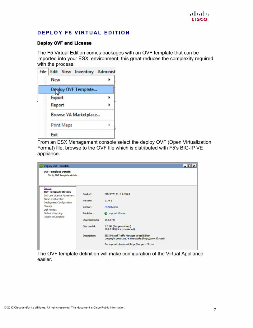
The F5 Virtual Edition comes packages with an OVF template that can be imported into your ESXi environment; this great reduces the complexity required with the process.
From an ESX Management console select the deploy OVF (Open Virtualization Format) file, browse to the OVF file which is distributed with F5’s BIG-IP VE appliance.
The OVF template definition will make configuration of the Virtual Appliance easier.

© 2012 Cisco and/or its affiliates. All rights reserved. This document is Cisco Public Information.
8
Carefully Read and Accept the license agreement for F5 to continue.
Select which ESX Inventory you’d like to install the VM to

© 2012 Cisco and/or its affiliates. All rights reserved. This document is Cisco Public Information.
9
Now select the no of CPUs you have a license for
Finally select the storage profile for the Virtual Machine
It is recommended that you Thick Provision your virtual machine

© 2012 Cisco and/or its affiliates. All rights reserved. This document is Cisco Public Information.
10
Once deployed you should select the console from the VM utility
From the console you may configure the management network *note* F5 must have multiple VLANs in order to facilitate correct operational segmentation

© 2012 Cisco and/or its affiliates. All rights reserved. This document is Cisco Public Information.
11
Enter the IP addresses for the management network; include the Default Route for that network, so that it is accessible from a browser.
Open and web browser and browse to the management IP address from the previous step default user and passwords are “admin”

© 2012 Cisco and/or its affiliates. All rights reserved. This document is Cisco Public Information.
12
You can then follow the wizard to configure your BIG-IP VE
Root and Admin accounts should be configured with disparate passwords
You’ll then need to license your server either Automatically or Manually – selecting Automatic will require internet access.

© 2012 Cisco and/or its affiliates. All rights reserved. This document is Cisco Public Information.
13
If proceeding manually go to F5’s website (https://activate.f5.com/license/dossier.jsp) and either upload or paste your dossier
To proceed you should read and accept their license agreement

© 2012 Cisco and/or its affiliates. All rights reserved. This document is Cisco Public Information.
14
Go back to your installation instance and validate the license by pasting it below the Dossier Note: if for some reason you cannot perform this licensing step – the next screen will not be available to you.

© 2012 Cisco and/or its affiliates. All rights reserved. This document is Cisco Public Information.
15
Configure Resource Al location within LTM
Now that the appliance is licensed you may opt to configure its resources accordingly

© 2012 Cisco and/or its affiliates. All rights reserved. This document is Cisco Public Information.
16
As you can see the default settings here are adjusted to reflect the Virtual Appliances purpose
For the purpose of this technote we’ll be discussing only LTM (local traffic manager)
Lastly you may upload a certificate from you own CA in order to establish a trust on the management network.

© 2012 Cisco and/or its affiliates. All rights reserved. This document is Cisco Public Information.
17
F 5 L T M C O N F I G U R A T I O N
Setup a HTTP Profi le
Now that the appliance is configured and you’ve selected it’s intention and licensed LTM, a new menu will appear allowing you to configure Profiles, Policies, Pools and Nodes.
From the side banner select Local Traffic > Virtual Servers > Profiles > services > HTTP and Add Give your new Profile a name “WSA-Proxy”

© 2012 Cisco and/or its affiliates. All rights reserved. This document is Cisco Public Information.
18
As you can see we’ve opted to choose the inherited settings from the default HTTP profile
Ensure you add in the X-Forwarded-For headers that will insert the client’s IP address in an HTML header and the WSA will be able to extract this information for policy control as well as logging
All other settings can remain inherited from the default http profile

© 2012 Cisco and/or its affiliates. All rights reserved. This document is Cisco Public Information.
19
F5 Setup VIP + Pool
A Virtual IP address is required on the internal VLAN of the BigIP in order to facilitate outbound requests from your client/server VLAN. This VIP will then load balance across a number of webcache that will be defined in a pool.
or
From the Local Traffic > Virtual Servers > Virtual Server List – Select Add

© 2012 Cisco and/or its affiliates. All rights reserved. This document is Cisco Public Information.
20
Give your Virtual Server a name “WSA-VIP” in this case Enter a description Select a Type Enter the expectant source 0.0.0.0/0 is any or if this is Ipv6 Destination will be the VIP (Virtual IP address) for your WSA estate Add the Port or ports Mark the VIP enabled
When you expand the service to look at the advanced characteristics you’ll need to reflect the HTTP Profile you created above (this allows for XFF header insertion)

© 2012 Cisco and/or its affiliates. All rights reserved. This document is Cisco Public Information.
21
As you won’t be decrypting traffic on your LB for proxy, you may skip the settings here
Lastly Activate your VIP on the VLAN where you’re clients reside, in this case it’s internal. *note* for the purpose of this document we have 3 VLANs (Management, Internal and External)

© 2012 Cisco and/or its affiliates. All rights reserved. This document is Cisco Public Information.
22
As this is loadbalaner is Layer 4 we’ll want to perform NAT (to protect routing) Layer 2 insertion is also possible.
There is no need or requirement for any rewriting of traffic
There is no Acceleration required

© 2012 Cisco and/or its affiliates. All rights reserved. This document is Cisco Public Information.
23
We are not using iRules here
It is advisable to maintain persistence/statefullness for logging, authentication, caching purposes
Lastly we’ll need to establish where the BIG-IP will send the traffic once it’s received it through it’s VIP – here we’re creating a pool called “WSA Pool”

© 2012 Cisco and/or its affiliates. All rights reserved. This document is Cisco Public Information.
24
In the pool we have 2 virtual WSAs We’ve selected Weighted Least Connections (node) as this is a little more formulaic than round robin and should return better value in loadbalancing.
F 5 S E T U P H E A L T H M O N I T O R
Now that a pool has been created we may select from existing or create new Health Monitors. From the Local Traffic > Pools > Pools List

© 2012 Cisco and/or its affiliates. All rights reserved. This document is Cisco Public Information.
25
select the pool you created above “WSA-Pool”
Within the Properties of the Pool you may select from existing health monitors, in this case we’ve selected tcp_half_open this will test for the response from the WSA
You can see that the status of each member is Green

© 2012 Cisco and/or its affiliates. All rights reserved. This document is Cisco Public Information.
26
By selecting an individual member you may see the status of it, and also manually select to mark offline (in the case of maintenance window)

© 2012 Cisco and/or its affiliates. All rights reserved. This document is Cisco Public Information.
27
D E P L O Y I N G A V I R T U A L W S A
The Cisco Virtual WSA comes packages with an OVF template to accelerate and configure your ESX environment for you.
From vSphere Client Select “Deploy OVF Template…”
Browse to the relevant OVF file (unpacked from the compressed file downloaded from Cisco’s Support Site”

© 2012 Cisco and/or its affiliates. All rights reserved. This document is Cisco Public Information.
28
The OVF details will be display – Select next
Select where in your Inventory you would like to place the virtual server and give it an indexing name.
Now select the host you would like to run the Virtual Server on.

© 2012 Cisco and/or its affiliates. All rights reserved. This document is Cisco Public Information.
29
Select your storage array
Select to Thick Provision your Client (for production), thin can be used in an unsupported environment.

© 2012 Cisco and/or its affiliates. All rights reserved. This document is Cisco Public Information.
30
Map the various Interfaces to the vSwitch in your environment, each interface should exist on a different network. If multiple networks are unavailable disable the interface within the settings of the Virtual Machine (see below for details).
Once complete select to deploy and power on. You may then connect to the DHCP assigned IP address for the WSAv and follow the startup wizard. In order to find what IP address has been assigned to your WSAv open a console from within vSphere client.
© 2012 Cisco and/or its affiliates. All rights reserved. This document is Cisco Public Information.
31
For more information on setting up WSAv connector refer to technote “Setting up a WSA virtual appliance”
WSA Interface Settings
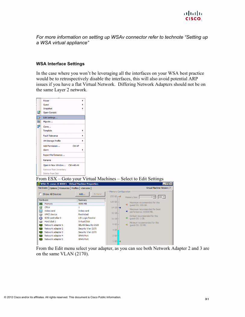
In the case where you won’t be leveraging all the interfaces on your WSA best practice would be to retrospectively disable the interfaces, this will also avoid potential ARP issues if you have a flat Virtual Network. Differing Network Adapters should not be on the same Layer 2 network.
From ESX – Goto your Virtual Machines – Select to Edit Settings
From the Edit menu select your adapter, as you can see both Network Adapter 2 and 3 are on the same VLAN (2170).

© 2012 Cisco and/or its affiliates. All rights reserved. This document is Cisco Public Information.
32
As you can see I’ve altered the status of Network Adapter 3, 4 and 5
By de-selecting “Connected” and “Connect at power on”
© 2012 Cisco and/or its affiliates. All rights reserved. This document is Cisco Public Information.
33
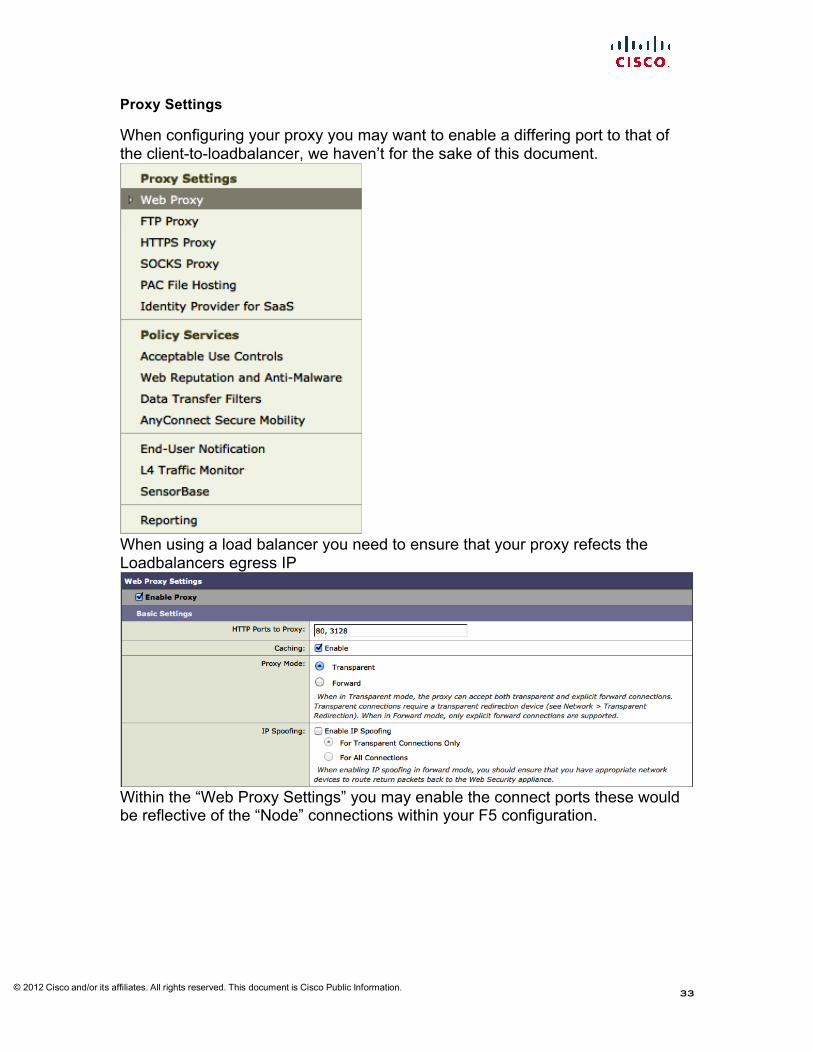
Proxy Settings
When configuring your proxy you may want to enable a differing port to that of the client-to-loadbalancer, we haven’t for the sake of this document.
When using a load balancer you need to ensure that your proxy refects the Loadbalancers egress IP
Within the “Web Proxy Settings” you may enable the connect ports these would be reflective of the “Node” connections within your F5 configuration.

© 2012 Cisco and/or its affiliates. All rights reserved. This document is Cisco Public Information.
34
Insert the shared, egress, or individual IP addresses of your load balancer, you may add multiple IP addresses in order to support multiple load balancers.
Log subscript ions
The %f can be added to the “Access Logs” subscription in order to log the XFF header 1394720820.580 31066 10.53.16.98 TCP_MISS/200 1416 CONNECT tunnel://twitter.com:443/ - DEFAULT_PARENT/proxy-wsa.esl.cisco.com - DEFAULT_CASE_12-DefaultGroup-DefaultGroup-NONE-NONE-NONE-DefaultGroup <IW_snet,5.9,0,"-",0,0,0,1,"-",-,-,-,"-",1,-,"-","-",-,-,IW_snet,-,"-","-","Unknown","Unknown","-","-",0.36,0,-,"Unknown","-",1,"-",-,-,"-","-"> - "10.53.16.98"

© 2012 Cisco and/or its affiliates. All rights reserved. This document is Cisco Public Information.
35
If using W3C Log format you may use the “cs(X-Forwarded-For)”
1394728962.233 926 10.53.16.98 TCP_MISS 200 2414 POST http://ocsp.verisign.com/ - DEFAULT_PARENT proxy-wsa.esl.cisco.com application/octet-stream DEFAULT_CASE_12-DefaultGroup-DefaultGroup-NONE-NONE-NONE-DefaultGroup <IW_comp,9.2,0,"-",0,0,0,1,"-",-,-,-,"-",0,0,"-","-",-,-,IW_comp,-,"Unknown","-","Unknown","Unknown","-","-",20.86,0,-,"Unknown","-",-,"-",-,-,"-","-"> - "10.53.16.98"

© 2012 Cisco and/or its affiliates. All rights reserved. This document is Cisco Public Information.
36
W S A A D D I T I O N A L C L I S E T T I N G S
yourWSAhostname> advancedproxyconfig Choose a parameter group: - MISCELLANEOUS - Miscellaneous proxy related parameters []> miscellaneous Enter values for the miscellaneous options: Would you like proxy to respond to health checks from L4 switches (always enabled if WSA is in L4 transparent mode)? [Y]> (as per this doc, we want to allow WSA to respond to health checks) Would you like proxy to perform dynamic adjustment of TCP receive window size? [N]> (No in this case as I’ve an upstream Proxy beyond the WSA) the default YES should be used in most cases. Mode of the proxy: 1. Explicit forward mode only 2. Transparent mode with L4 Switch or no device for redirection 3. Transparent mode with WCCP v2 Router for redirection [2]> (When the proxy is configured in mode 2 or 3 it will still respond to explicit requests, however if you configure the proxy in Mode 1 it will not participate in WCCP) Spoofing of the client IP by the proxy: 1. Disable 2. Enable for all requests 3. Enable for transparent requests only [1]> (No need to spoof the IP address upstream, by doing so you may end up with an asynchronous routing loop) Do you want to pass HTTP X-Forwarded-For headers? [N]> (no need unless there is a requirement upstream for XFF) Would you like proxy to log values from X-Forwarded-For headers in place of incoming connection IP addresses? [Y]> (this is to aid in troubleshooting, the client’s IP is reflected in the access log) Would you like the proxy to use client IP addresses from X-Forwarded-For headers? [Y]> (this is to aid policy config and reporting) Please enter the IP addresses for trusted downstream proxies (comma separated): [['SNAT’ed Address']]> (this address can be the floating, SNAT’ed address of the loadbalancer)

© 2012 Cisco and/or its affiliates. All rights reserved. This document is Cisco Public Information.
37
P E R F O R M I N G A N U P G R A D E O F A N O D E T H A T I S P A R T O F A N F 5 P O O L
Once the Load Balancer and proxy are setup, begin testing of the policy on the WSA. As there is a load balancer in situe, you may kick off an upgrade of one of the nodes from the pool by marking it unavailable to the LB.
From > Local Traffic > Nodes > Node List
Select the server you’d like to take offline, my preference is always to select the most used server
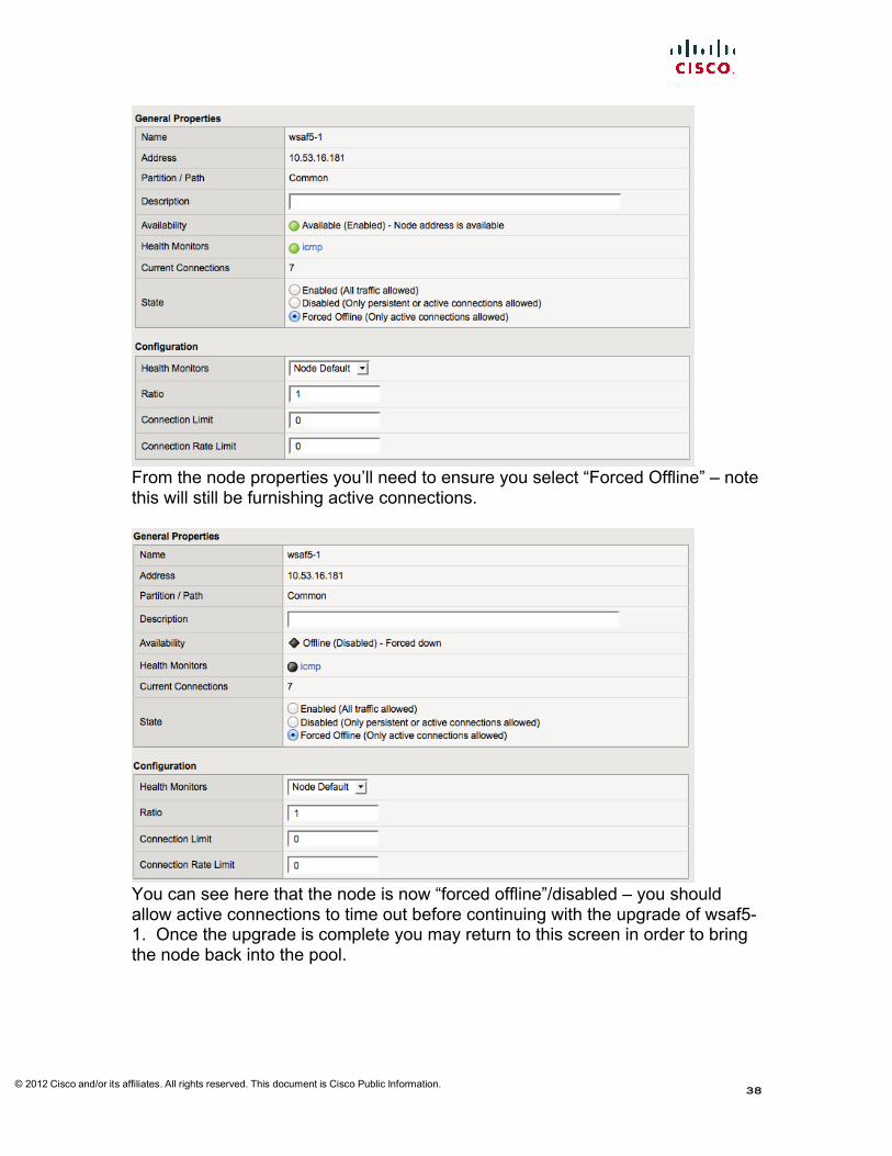
if you simply select disable the Load Balancer will retain statefullness and continue to service the node although marked offline
© 2012 Cisco and/or its affiliates. All rights reserved. This document is Cisco Public Information.
38
From the node properties you’ll need to ensure you select “Forced Offline” – note this will still be furnishing active connections.
You can see here that the node is now “forced offline”/disabled – you should allow active connections to time out before continuing with the upgrade of wsaf5-1. Once the upgrade is complete you may return to this screen in order to bring the node back into the pool.
© 2012 Cisco and/or its affiliates. All rights reserved. This document is Cisco Public Information.
39
S N A T , N A T , T R A N S L A T I O N S
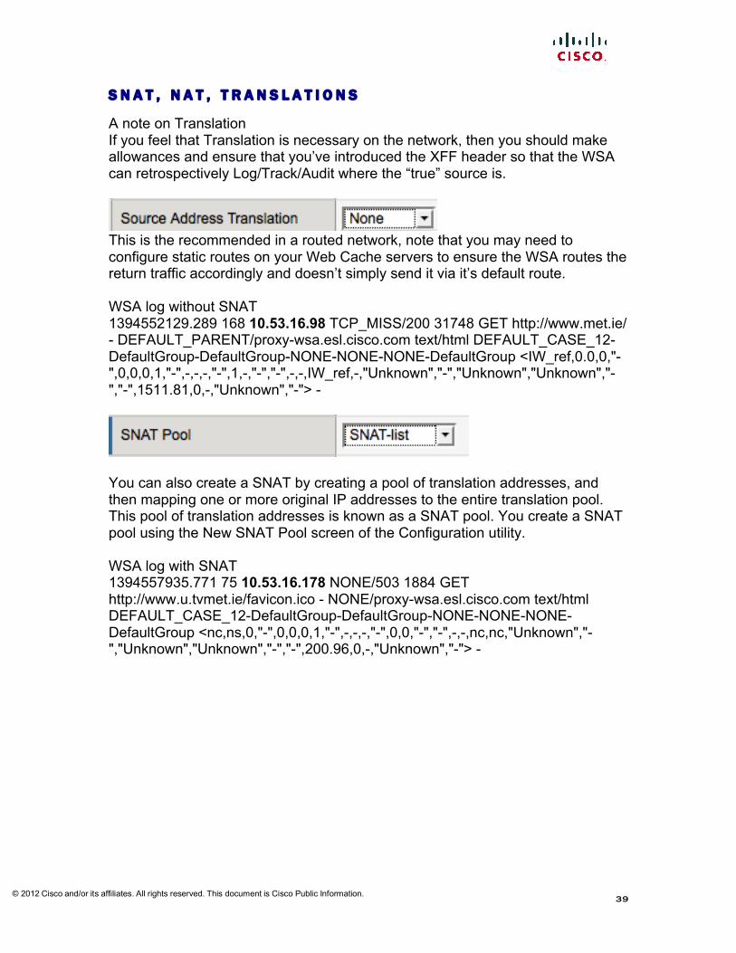
A note on Translation If you feel that Translation is necessary on the network, then you should make allowances and ensure that you’ve introduced the XFF header so that the WSA can retrospectively Log/Track/Audit where the “true” source is.
This is the recommended in a routed network, note that you may need to configure static routes on your Web Cache servers to ensure the WSA routes the return traffic accordingly and doesn’t simply send it via it’s default route. WSA log without SNAT 1394552129.289 168 10.53.16.98 TCP_MISS/200 31748 GET http://www.met.ie/ - DEFAULT_PARENT/proxy-wsa.esl.cisco.com text/html DEFAULT_CASE_12-DefaultGroup-DefaultGroup-NONE-NONE-NONE-DefaultGroup <IW_ref,0.0,0,"-",0,0,0,1,"-",-,-,-,"-",1,-,"-","-",-,-,IW_ref,-,"Unknown","-","Unknown","Unknown","-","-",1511.81,0,-,"Unknown","-"> -
You can also create a SNAT by creating a pool of translation addresses, and then mapping one or more original IP addresses to the entire translation pool. This pool of translation addresses is known as a SNAT pool. You create a SNAT pool using the New SNAT Pool screen of the Configuration utility. WSA log with SNAT 1394557935.771 75 10.53.16.178 NONE/503 1884 GET http://www.u.tvmet.ie/favicon.ico - NONE/proxy-wsa.esl.cisco.com text/html DEFAULT_CASE_12-DefaultGroup-DefaultGroup-NONE-NONE-NONE-DefaultGroup <nc,ns,0,"-",0,0,0,1,"-",-,-,-,"-",0,0,"-","-",-,-,nc,nc,"Unknown","-","Unknown","Unknown","-","-",200.96,0,-,"Unknown","-"> -

© 2012 Cisco and/or its affiliates. All rights reserved. This document is Cisco Public Information.
40
The SNAT automap feature automatically selects one of the systems self IP addresses (typically a floating self IP address of the egress VLAN), and maps it to the original IP address or addresses that you specify during SNAT creation. When you use this feature, you do not need to explicitly specify a translation address. When automatically choosing a self-IP address to map to the specified original IP address, the system gives preference to floating self-IP addresses over static (non-floating) self-IP addresses. This prevents any interruption in service when failover occurs. Note that if no floating self-IP address is currently assigned to the egress VLAN, the system uses the floating IP address of a non-egress VLAN instead. In testing it was found that the Auto Map feature may ignore the subnet to which the virtual LB is configured and may select the top level available IP on a subnet 10.53.16.176/29 we found the LB to be utilising 10.53.0.1 for SNAT. When testing these features be mindful that although config has change the F5 will retain connections, so when polling box you’ll find mixed results. WSA log with AutoMap 1394554596.439 122 10.53.0.1 TCP_MISS/200 9564 GET http://www.met.ie/weathermaps/meteoalarm.jpg?1645 - DEFAULT_PARENT/proxy-wsa.esl.cisco.com image/jpeg DEFAULT_CASE_12-DefaultGroup-DefaultGroup-NONE-NONE-NONE-DefaultGroup <IW_ref,0.0,0,"-",0,0,0,1,"-",-,-,-,"-",1,-,"-","-",-,-,IW_ref,-,"Unknown","-","Unknown","Unknown","-","-",627.15,0,-,"Unknown","-"> - Note the F5 server will use an IP address from its configured range. However in this case we are not seeing the F5 respect the subnetting.

© 2012 Cisco and/or its affiliates. All rights reserved. This document is Cisco Public Information.
41
U N D E R S T A N D I N G L O A D B A L A N C I N G A L G O R I T H M S
The Load Balacing method is choosen from the Local Traffic > Pools > Members Page
Please note that Dynamic load balancing isn’t supported. If you were to mix differing Appliances or Virtual appliances it may be advantageous to use Ratio initially (based on sizing guides), but then more towards Dynamic Ratio or Predicitive allow the F5 LTM to make intelligent Load Balancing decsions. Dynamic Ratio load balancing is similar to Ratio mode, except that weights are based on continuous monitoring of the servers and are therefore continually changing. This is a dynamic load balancing method, distributing connections based on various aspects of real-time server performance analysis, such as the number of current connections per node or the fastest node response time. Fastest Passes a new connection based on the fastest response of all currently active nodes in a pool. This method might be particularly useful in environments where nodes are distributed across different logical networks.
© 2012 Cisco and/or its affiliates. All rights reserved. This document is Cisco Public Information.
42
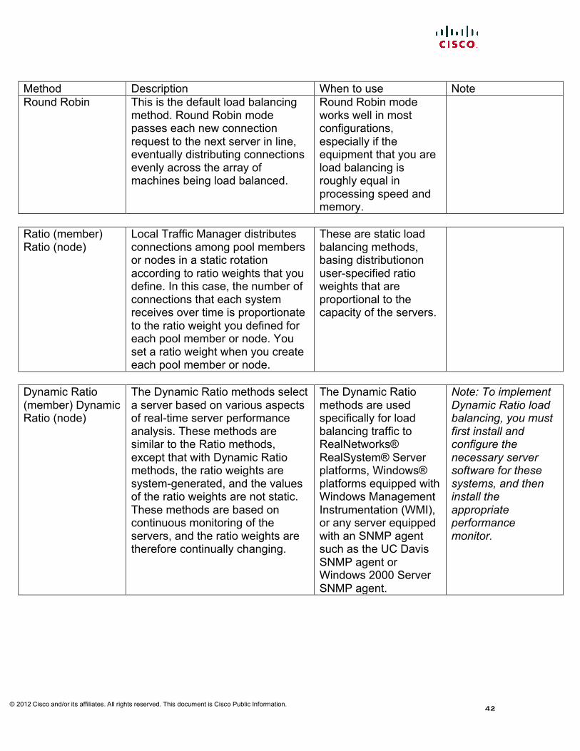
Method Description When to use Note Round Robin This is the default load balancing
method. Round Robin mode passes each new connection request to the next server in line, eventually distributing connections evenly across the array of machines being load balanced.
Round Robin mode works well in most configurations, especially if the equipment that you are load balancing is roughly equal in processing speed and memory.
Ratio (member) Ratio (node)
Local Traffic Manager distributes connections among pool members or nodes in a static rotation according to ratio weights that you define. In this case, the number of connections that each system receives over time is proportionate to the ratio weight you defined for each pool member or node. You set a ratio weight when you create each pool member or node.
These are static load balancing methods, basing distributionon user-specified ratio weights that are proportional to the capacity of the servers.
Dynamic Ratio (member) Dynamic Ratio (node)
The Dynamic Ratio methods select a server based on various aspects of real-time server performance analysis. These methods are similar to the Ratio methods, except that with Dynamic Ratio methods, the ratio weights are system-generated, and the values of the ratio weights are not static. These methods are based on continuous monitoring of the servers, and the ratio weights are therefore continually changing.
The Dynamic Ratio methods are used specifically for load balancing traffic to RealNetworks® RealSystem® Server platforms, Windows® platforms equipped with Windows Management Instrumentation (WMI), or any server equipped with an SNMP agent such as the UC Davis SNMP agent or Windows 2000 Server SNMP agent.
Note: To implement Dynamic Ratio load balancing, you must first install and configure the necessary server software for these systems, and then install the appropriate performance monitor.

© 2012 Cisco and/or its affiliates. All rights reserved. This document is Cisco Public Information.
43
Fastest (node) Fastest (application)
The Fastest methods select a server based on the least number of current sessions. These methods require that you assign both a Layer 7 and a TCP type of profile to the virtual server.
The Fastest methods are useful in environments where nodes are distributed across separate logical networks.
Note: If the OneConnectTM feature is enabled, the Least Connections methods do not include idle connections in the calculations when selecting a pool member or node. The Least Connections methods use only active connections in their calculations.
Least Connections (member) Least Connections (node)
The Least Connections methods are relatively simple in that Local Traffic Manager passes a new connection to the pool member or node that has the least number of active connections.
The Least Connections methods function best in environments where the servers have similar capabilities. Otherwise, some amount of latency can occur.
Note: If the OneConnect feature is enabled, the Least Connections methods do not include idle connections in the calculations when selecting a pool member or node. The Least Connections methods use only active connections in their calculations.

© 2012 Cisco and/or its affiliates. All rights reserved. This document is Cisco Public Information.
44
Weighted Least Connections (member) Weighted Least Connections (node)
Like the Least Connections methods, these load balancing methods select pool members or nodes based on the number of active connections. However, the Weighted Least Connections methods also base their selections on server capacity. The Weighted Least Connections (member) method specifies that the system uses the value you specify in Connection Limit to establish a proportional algorithm for each pool member. The system bases the load balancing decision on that proportion and the number of current connections to that pool member.
Weighted Least Connections methods work best in environments where the servers have differing capacities. For example, if two servers have the same number of active connections butoneserverhasmorecapacity than the other, Local Traffic Manager calculates the percentage of capacity being used on each server and uses that percentage in its calculations.
Note: If the OneConnect feature is enabled, the Weighted Least Connections methods do not include idle connections in the calculations when selecting a pool member or node. The Weighted Least Connections methods use reaching capacity. If you have servers with varying capacities, consider using the Weighted Least Connections methods instead.

© 2012 Cisco and/or its affiliates. All rights reserved. This document is Cisco Public Information.
45
U N D E R S T A N D I N G H E A L T H C H E C K S
You can instruct the Load Balancer to check the health of servers/nodes and server farms by configuring health probes (sometimes referred to as keepalives). After you create a probe, you assign it to a real server or a server farm/pool. A probe can be one of many types, including TCP, ICMP, Telnet, HTTP, and so on. You can also configure scripted probes using the irules. The Load Balancer sends out probes periodically to determine the status of a server, verifies the server response, and checks for other network problems that may prevent a client from reaching a server. Based on the server response, the Load Balancer can place the node/application in or out of service, and, based on the status of the servers in the pool Simple monitoring Simple monitoring merely determines whether the status of a node is up or down. Simple monitors do not monitor pool members (and therefore, individual protocols, services, or applications on a node), but only the node itself. The system contains two types of simple monitors, ICMP and TCP_ECHO. Active monitoring Active monitoring checks the status of a pool member or node on an ongoing basis, at a set interval. If a pool member or node being checked does not respond within a specified timeout period, or the status of a node indicates that performance is degraded, Local Traffic Manager can redirect the traffic to another pool member or node. There are many types of active monitors. Each type of active monitor checks the status of a particular protocol, service, or application. For example, one type of monitor is HTTP. An HTTP type of monitor allows you to monitor the availability of the HTTP service on a pool, pool member, or node. A WMI type of monitor allows you to monitor the performance of a node that is running the Windows Management Instrumentation (WMI) software. Active monitors fall into two categories: Extended Content Verification (ECV) monitors, and Extended Application Verification (EAV) monitors. Passive monitoring Passive monitoring occurs as part of a client request. This kind of monitoring checks the health of a pool member based on a specified number of connection attempts or data request attempts that occur within a specified time period. If, after the specified number of attempts within the defined interval, the system cannot either connect to the server or receive a response, or if the system receives a bad response, the system marks the pool member as down. There is only one type of passive monitor, called an Inband monitor.
© 2012 Cisco and/or its affiliates. All rights reserved. This document is Cisco Public Information.
46
Monitoring Method
Benefits Constraints
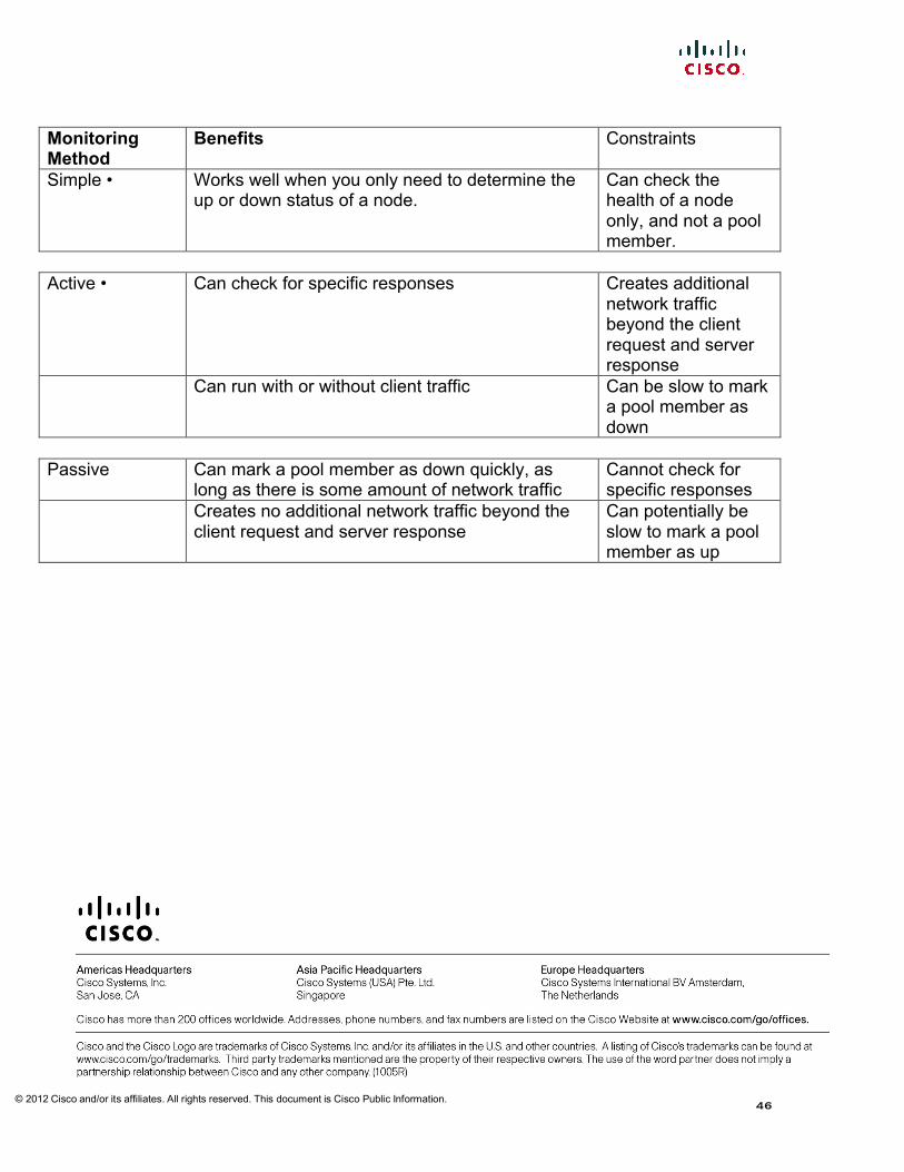
Simple • Works well when you only need to determine the up or down status of a node.
Can check the health of a node only, and not a pool member.
Active • Can check for specific responses Creates additional
network traffic beyond the client request and server response
Can run with or without client traffic Can be slow to mark a pool member as down
Passive Can mark a pool member as down quickly, as
long as there is some amount of network traffic Cannot check for specific responses
Creates no additional network traffic beyond the client request and server response
Can potentially be slow to mark a pool member as up