systems and software product line engineering
TRANSCRIPT

Encyclopedia of Software Engineering DOI: 10.1081/E-ESE-120048252Copyright © 2013 by Taylor & Francis. All rights reserved. 1
Systems and Software Product Line Engineering
Charles KruegerPaul ClementsBigLever Software, Inc., Austin, Texas, U.S.A.
AbstractSystems and software product line engineering is a way to engineer a portfolio of related products in an efficient manner, taking full advantage of the products’ similarities while respecting and managing their differences. Considering a portfolio as a single entity to be managed, as opposed to a multitude of separate products to be managed, brings enormous efficiencies in production and maintenance; these efficiencies are delivering order-of-magnitude improvements in engineering cost, time to market, staff productivity, product line scalability, and quality. This entry defines and explores the concepts central to systems and software product line engineering and five key characteristics that are central to its modern practice.
INTRODUCTION
Systems and software product line engineering is a way to engineer a portfolio of related products in an efficient manner, taking full advantage of the products’ similarities while respecting and managing their differences. By “engineer,” we mean all of the activities involved in plan-ning, producing, delivering, deploying, sustaining, and retiring products.
Considering a portfolio as a single entity to be man-aged, as opposed to a multitude of separate products to be managed, brings enormous efficiencies in production and maintenance; these efficiencies are delivering order-of-magnitude improvements in engineering cost, time to market, staff productivity, product line scalability, and quality.[1]
Hard goods factories have long had the ability to pro-duce variations of the same basic product. Think of the size/color choice you can make for a pair of shoes, or the hundreds of options available on an automobile. Sys-tems and software product line engineering applies this same concept to the engineering artifacts that are in digital or “soft” form and that support a product—its requirements, designs, implementation, project plans, test cases, user documentation, and more, all of which need to be managed and produced in variants that match the product.
This entry defines and explores the concepts central to systems and software product line engineering. It describes the benefits that organizations employing it have enjoyed, which are substantial. It describes the software roots of the field, and talks about its evolution to its current form and the five key characteristics com-prised by modern software and systems product line engineering.
What is Systems and Software Product Line Engineering?
Systems and software product line engineering, often abbreviated as product line engineering (PLE), refers to the disciplined engineering of a portfolio of related products using a common set of shared assets and a common means of production.
Products
The products in the portfolio are described by the proper-ties they have in common with each other and the varia-tions that set them apart. The products can comprise any combination of
● software, ● systems in which software runs, or ● non-software systems that have software-representable
artifacts (such as engineering models or development plans) associated with them.
Throughout this entry, when we refer to a product, we usually mean not only the primary entity being built and delivered but also all of the artifacts that are produced along with it. Some of these support the engineering process (such as requirements, project plans, design modes, and test cases), while others are delivered alongside the thing being built (such as user manuals, shipping labels, and parts lists).
Assets
Assets are the “soft” artifacts associated with engineering life cycle of the products, the building blocks of the products

2 Systems and Software Product Line Engineering
in the product line. Assets can be whatever artifacts are rep-resentable with software and either compose a product or support the engineering process to create a product. These can include but are not limited to the following:[2]
● Requirements ● Design specifications ● Design models ● Source code ● Build files ● Test plans and test cases ● User documentation ● Repair manuals and installation guides ● Project budgets, schedules, and work plans ● Product calibration and configuration files ● Data models and parts lists
Assets in PLE are engineered to be shared across the product line. Assets are designed with built-in variation points, which are places in the asset that change depending on the product in which the asset is used. When a product is built, a statement of the product’s distinguishing charac-teristics is applied to “exercise” these variation points (i.e., cause the change in the asset to occur to meet the needs of the product).[3] Variation points use variation mechanisms to impart product line diversity; these mechanisms include macros in code, substituting one variant of the artifact for another; runtime conditionals and configuration files; attri-butes and filters; model and text transformations; feature mappings, parameterization, and many more.
Means of Production
The means of production is the mechanism that exercises the assets’ variation points to produce configured versions that together constitute the artifact set for one of the prod-ucts in the product line.[4] Configuring the shared assets for each product in turn produces the entire set of products.
The means of production can be manual, but for product lines of any size or frequency of change, manual produc-tion is impractical; some form of automation is required.
Low-end automation might be a programming lan-guage’s macro processor combined with compiler flags and #ifdef statements to turn blocks of code on or off. However, this scheme scales poorly, may not trace well across different kinds of artifacts, and in fact may not work for, for example, requirements or design models. This leads to an ad hoc collection of techniques for expressing varia-tion, each specialized to its own type of asset.
At the high end of the spectrum are special-purpose PLE tools that tie variation points to a central feature model for the entire product line and provide a set of mechanisms for defining and exercising the variation points in all kinds of assets. Examples of such tools include Gears,[5,6] pure::variants,[7] XVCL,[8] Dopler,[9] and more.
An analogy with factory-based manufacturing serves to illuminate the concepts.
Manufacturers have long used analogous engineering techniques to create a product line of similar products using a common factory that assembles and configures parts designed to be reused across the varying products in the product line. For example, automotive manufacturers can create thousands of unique variations of one car model using a single pool of parts carefully designed to be con-figurable and factories specifically designed to configure and assemble those parts.
In PLE, the configurator is the factory and the assets represent the factory’s supply chain. A statement of the properties desired in the end product tells the configurator how to configure the assets.
The essence of PLE—for systems and software, as for manufacturing—is the focus on the single system rather than many products. The “system” in this case consists of the production line, which enables the rapid production of any variant of any of the assets for any of the products in the portfolio. An PLE production line consists of
● a collection of soft assets (i.e., assets that can be repre-sented digitally) that are shared across the products,
● a set of specifications that define the products, and ● the configurator that applies a product specification
to the assets in order to produce each product in the portfolio.
Once the production line is established, engineering assets and products are instantiated rather than manually created.
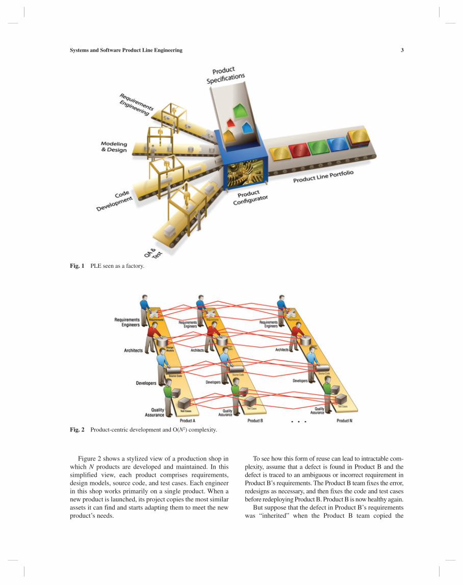
In Fig. 1, the “factory’s” supply chain is at the left, in the form of shared assets that are configurable because they include variation points that are expressed in terms of the features available in each of the products. A product specification at the top tells the configurator how to con-figure the assets coming in from the left. The resulting products, assembled from the configured assets, emerge on the right.
PLE CONTRASTED WITH PRODUCT-CENTRIC DEVELOPMENT
PLE stands in contrast to classical product-centric develop-ment, in which each individual product is developed and evolved independently from other products, or (at best) starts out as a cloned copy of a similar product that is then changed to suit the new product’s specific needs. Product-centric development takes very little advantage of the com-monalities among products in a portfolio after the initial clone operation. In particular, it derives very little benefit from commonality in a product’s sustainment or mainte-nance phase, where data show that most products consume up to 90% of their project resources.
Systems and Software Product Line Engineering 3
To see how this form of reuse can lead to intractable com-plexity, assume that a defect is found in Product B and the defect is traced to an ambiguous or incorrect requirement in Product B’s requirements. The Product B team fixes the error, redesigns as necessary, and then fixes the code and test cases before redeploying Product B. Product B is now healthy again.
But suppose that the defect in Product B’s requirements was “inherited” when the Product B team copied the
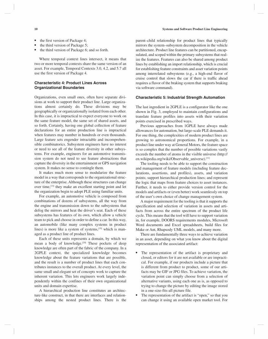
Figure 2 shows a stylized view of a production shop in which N products are developed and maintained. In this simplified view, each product comprises requirements, design models, source code, and test cases. Each engineer in this shop works primarily on a single product. When a new product is launched, its project copies the most similar assets it can find and starts adapting them to meet the new product’s needs.
Fig. 1 PLE seen as a factory.
Fig. 2 Product-centric development and O(N2) complexity.

4 Systems and Software Product Line Engineering
hiring, acquiring better tools, improving processes, and the like, but these measures result in modest improvements at best and are ultimately ineffective against an engineering problem that is growing as the square of the number of products in the portfolio. In organizations where engineer-ing capability is about to be (or has been) swamped by the engineering complexity of their portfolio, missed dead-lines, decreasing quality, and lower employee morale are the norms.
Figure 1 alluded to PLE as a factory, and that analogy can be brought to bear to remedy the O(N2) problem of port-folio management. In a manufacturing factory, a defective product would not be fixed by one-off repairs to the product itself. Rather, the factory, its supply chain, and the manufac-turing process itself would be scoured to find the source of the defect.
So it is with PLE. Rather than fixing a defective prod-uct, PLE engineers fix the shared asset(s) that need to be modified (perhaps by adding a new variation point) in order to produce the product correctly. Then, the configura-tor is used to regenerate the product, as well as any other product affected by the changes in the shared assets.
Since regeneration has a low and fixed cost, it matters very little whether 2, 200, or 2000 products need to be regenerated. Thus, fixing a defect, making a systematic enhancement, or carrying out any other kind of portfolio-wide change becomes an O(N) operation.
In Fig. 3 suppose the same defect in Product B occurs that we described earlier, and suppose the defect is traced to Product B’s requirements. Under the factory paradigm,
requirements from Product A. Suppose further that the source code for Product N was copied from Product B’s (defective) source code, and the test cases for Product N were similarly “borrowed” from Product A’s (inadequate) test cases.
To really root out the defect from the entire portfolio, each of the N product teams should really confer with each of the other N – 1 product teams. These communication paths are shown in red in Fig. 2. This communication obli-gation imposes an overhead that grows as the square of the number of products. So, in a relatively modest product line of 30 products, some 900 interproject communication paths should be activated. This complexity will quickly over-whelm any engineering staff; in order to get their products out of the door on time and on budget, each product team will focus more on their product silo and less on taking advantage of the commonalities and interdependencies among the other products. The result is divergent product silos, low degrees of sharing, and high duplication of effort across the product silos to fix the same defect multiple times in multiple products, or to independently implement the same enhancements in different ways in different products.
PLE AND THE FACTORY PARADIGM
Clearly, product-centric development lacks the ability to scale. Productivity, product quality, or economies of pro-duction will degrade as the portfolio grows larger. Organi-zations can improve their engineering capabilities through
Fig. 3 PLE and O(N) complexity.

Systems and Software Product Line Engineering 5
descriptively useful. We can identify the Baby Boomer, Gen-X, Gen-Y, Tween, and Millennium Generations. Fighter aircraft are generally thought to be in their fifth generation[17] and programming languages in their fourth or fifth (opinions vary).[18] Current standards for mobile broadband devices are labeled “4G.”
In the same spirit, we characterize some early and long-standing approaches to product line engineering as fi rst generation. These include the following:
● Parnas’ seminal paper on product families in 1976[19] instilled the idea that similar programs could be treated as a family rather than as a separate and unrelated set. Parnas characterized software evolution as a tree of decision possibilities. Every design decision leads down a different path of the tree. The family of possible programs occupies the leaves of the tree. Making a change involves backtracking up the tree and choosing a different path downward, ending at a different leaf. Obviously, the less backtracking required, the easier the change. Parnas argued that, to accomplish this, we should make the most stable design decisions early, corresponding to nodes closer to the tree’s root, and the most volatile ones late.
● Domain analysis, exemplified by the feature-oriented domain analysis (FODA) method,[20] provided a way to express the commonality and variations found in a set of systems or products. FODA provided a useful defini-tion of a feature, which is “A prominent or distinctive user-visible aspect, quality, or characteristic of a soft-ware system or systems,” and this definition still serves well in the PLE world. FODA led the way to a wide variety of feature modeling languages, which allow domain modelers to express features and their allow-able combinations.
● The software reuse movement[21,22] that came to fruition in the early 1990s emphasized code repositories. By and large, this movement exemplified opportunistic reuse (i.e., searching to see if a unit of software exists to fill a need as it arises), as opposed to planned reuse. Its primary contribution to PLE was to instill the notion that software systems might not (or should not) be built from scratch.
● The U.S. Department of Defense’s Advanced Research Projects Agency’s STARS (Software Technology for Adaptable, Reliable Systems) project turned its attention to software product line development in the early to mid-1990s.[23] STARS instilled the dichotomy between domain engineering (the construction of reusable core assets) and application engineering (the selection, application, and augmentation of those assets to build products). Applica-tion engineering is often said to include creating any assets used in a single product and promoting them to core assets only if subsequently used in more than one product.
● Generative programming[24] involves the use of domain-specific languages in which to specify a product and a
engineers work on shared assets (requirements, design, and so forth) that apply across the entire portfolio. And so the portfolio’s requirements engineers work to fix the defect in a way that not only fixes Product B but also applies across the whole product line. In other words, the defect is fixed on the left, and not in Product B’s “silo.” Then, Product B and any other affected products are regenerated using the product configurator.
DEMONSTRATED BENEFITS OF PLE
PLE is of interest because of remarkable efficiencies it has shown in the development process. The Software Engi-neering Institute lists the following benefits associated with software product lines:[10]
● Large-scale productivity gains ● Decreased time to market ● Increased product quality ● Decreased product risk ● Increased market agility ● Increased customer satisfaction ● More efficient use of human resources ● Ability to affect mass customization ● Ability to maintain market presence ● Ability to sustain unprecedented growth
Numerous case studies of PLE have shown substantial measured improvements in time to market, cost, product quality, product line scalability, and developer product-ivity, compared to product-centric development.[11,12,13,14] A few of the many published examples are as follows:
● The U.S. Army expects to save $584 million in devel-opment costs by procuring a family of live training sys-tems as a product line rather than a series of separate acquisitions.[15]
● Cummins, Inc., reports that as a result of building the software inside their engines using PLE, software proj-ects that used to take a year now take about a week.[16]
● MarketMaker Software AG reported that PLE led to a 2×–4× reduction in time to market and a reduction in maintenance costs of around 60%.[16]
● Hewlett-Packard reports that with a product line approach, they were able to build products 10 times as complex, with 1/4 of the staff, in 1/3 of the time, and with 1/25 of the number of bugs of earlier products.[16]
EARLY APPROACHES AND FIRST-GENERATION PLE
For products that embody software, PLE is an extension of software product line engineering.
“Generations” are hard to pin down precisely and do not have impermeable boundaries, but the concept can be

6 Systems and Software Product Line Engineering
In 2GPLE, there is a marked contrast (or at least exten-sion) to the four characteristics of first-generation product line engineering (1GPLE) outlined above:
1. Application engineering shrinks to almost nothing; products are produced through the use of high-end industrial strength automation that configures the shared assets appropriately for each product.
2. All artifacts, software and otherwise, are treated equally. As assets, they are endowed with variation points expressed using the same language constructs, for a consistent representation of the configurability available across all artifacts. This yields consistent and traceable variation management in artifacts across the full engineering life cycle.
3. Features have evolved from a general concept in domain analysis to a central role in variation manage-ment. The variation points in an asset are defined by naming the features and feature combinations under which each configuration applies. Features become the lingua franca to express product differences in all phases of the life cycle.
4. A simplified CM policy strongly discriminates between managing shared assets and managing prod-ucts. In fact, 2GPLE CM explicitly declines to manage product versions, but only shared asset versions.[2] New versions of products are defined (like any other prod-uct) with a combination of features specific to it and produced by configuring the shared assets accordingly.
A fifth contrasting characteristic of 2GPLE delivers an essential capability for large-scale product lines that was stated as a possibility but never central to 1GPLE.
5. Feature models with encapsulating constructs to facili-tate hierarchical product lines[33] and cooperative feature model development across organizational boundaries. This extends the architectural concept of a “system of systems” to support a “product line of product lines”.
We will cover each of the five characteristics of 2GPLE in depth, beginning with the importance of features.
Characteristic 1: Features as the Lingua Franca to Express Product Differences Across the Life cycle
A feature, to paraphrase Kang et al.[20], is a distinguishing characteristic of a product, usually visible to the customer or user of that product. An example is a function that one product can perform that others cannot.
The concept of “feature” allows a consistent abstraction to be employed when making choices from a whole product configuration all the way down to the deployment of soft-ware components within a low-level subsystem in the architecture. A bill-of-features (analogous to a bill-of-mate-rials, but defining a product in terms of its features rather
generator to process a product description written in that language to turn out a product. In 1999, Weiss and Lai adopted this approach for a product line methodol-ogy called FAST (Family-Oriented Abstraction, Speci-fication, and Translation).[25]
● Case studies of successful software product lines began to emerge in the mid-1990s. These included STARS demon-stration projects, but also included commercial successes (e.g., Brownsword and Clements[26]). These revealed that successful product lines required more than a technical approach, but also strong management and business acu-men (e.g., Bergey et al.[27]). Movements began to coalesce to explore product lines from this more holistic approach: first in Europe as a series of Program Families work-shops,[28] and then in the United States with the creation of the Product Line Practice research program at the Software Engineering Institute[28] and its creation of the Software Product Line Conference (SPLC) series of international conferences (www.splc.net).[29]
A distillation of first-generation approaches includes the following:
1. A strong dichotomy between domain engineering and application engineering, or core asset development and product development. Application engineering is often said to include creating any assets used only in a single product and promoting them to core asset status only if subsequently used in more than one product. Application engineering includes the obligation to choose a production strategy—that is, a way to turn the shared assets into products.[30]
2. Explicit inclusion of non-software artifacts in the col-lection of core assets, but an unmistakable emphasis on software (under the umbrella of an all-encompassing software architecture) as the principal kind of core asset.
3. Focus on features as the language to describe a product line’s domain and a way to discriminate products from each other in that domain.
4. Acknowledgment of configuration management as an essential practice under PLE, but without a strong dis-tinction between core asset configuration management (CM) and product CM.
These approaches have yielded a rich legacy of product line success, as evidenced by a plethora of case studies. The newer approaches we describe below build on them.
SECOND-GENERATION PLE
Recently, a newer set of approaches has emerged that together have been referred to as second-generation prod-uct line engineering (2GPLE).[31,32] This characterization represents seen-in-practice extensions—some minor, some fundamental—to the early paradigm that was centered mainly on core asset production and product derivation.
Systems and Software Product Line Engineering 7
sport package, and economy package” would be an enumer-ation type since the choice is mutually exclusive.
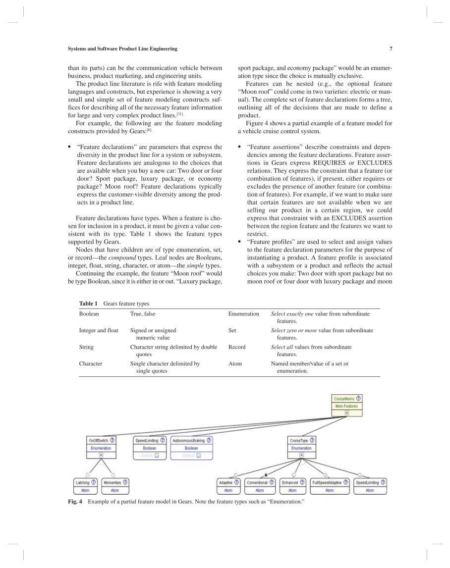
Features can be nested (e.g., the optional feature “Moon roof” could come in two varieties: electric or man-ual). The complete set of feature declarations forms a tree, outlining all of the decisions that are made to define a product.
Figure 4 shows a partial example of a feature model for a vehicle cruise control system.
● “Feature assertions” describe constraints and depen-dencies among the feature declarations. Feature asser-tions in Gears express REQUIRES or EXCLUDES relations. They express the constraint that a feature (or combination of features), if present, either requires or excludes the presence of another feature (or combina-tion of features). For example, if we want to make sure that certain features are not available when we are selling our product in a certain region, we could express that constraint with an EXCLUDES assertion between the region feature and the features we want to restrict.
● “Feature profiles” are used to select and assign values to the feature declaration parameters for the purpose of instantiating a product. A feature profile is associated with a subsystem or a product and reflects the actual choices you make: Two door with sport package but no moon roof or four door with luxury package and moon
than its parts) can be the communication vehicle between business, product marketing, and engineering units.
The product line literature is rife with feature modeling languages and constructs, but experience is showing a very small and simple set of feature modeling constructs suf-fices for describing all of the necessary feature information for large and very complex product lines.[31]
For example, the following are the feature modeling constructs provided by Gears:[6]
● “Feature declarations” are parameters that express the diversity in the product line for a system or subsystem. Feature declarations are analogous to the choices that are available when you buy a new car: Two door or four door? Sport package, luxury package, or economy package? Moon roof? Feature declarations typically express the customer-visible diversity among the prod-ucts in a product line.
Feature declarations have types. When a feature is cho-sen for inclusion in a product, it must be given a value con-sistent with its type. Table 1 shows the feature types supported by Gears.
Nodes that have children are of type enumeration, set, or record—the compound types. Leaf nodes are Booleans, integer, float, string, character, or atom—the simple types.
Continuing the example, the feature “Moon roof” would be type Boolean, since it is either in or out. “Luxury package,
Table 1 Gears feature types
Boolean True, false Enumeration Select exactly one value from subordinate features.
Integer and float Signed or unsigned numeric value
Set Select zero or more value from subordinate features.
String Character string delimited by double quotes
Record Select all values from subordinate features.
Character Single character delimited by single quotes
Atom Named member/value of a set or enumeration.
Fig. 4 Example of a partial feature model in Gears. Note the feature types such as “Enumeration.”
8 Systems and Software Product Line Engineering
with attributes that differentiate feature variations in require-ments. Further, the design team has adopted a Unified Mod-eling Language (UML) tool and has embraced inheritance as the mechanism for managing PLE design variations. The development team is using a FODA feature model drawn in a graphical editor, plus #ifdefs, build flags, and CM branches to manage implementation variations. Finally, the test team has adopted clone and own of test plan sections, stored in appropriately named file system directories to manage their PLE test plan variations. Now imagine what would be needed to create a complete PLE lifecycle solu-tion that integrates into a larger business process model. How do the requirements database attributes and tagged requirements relate and trace to the subtypes and super-types in the design models? How do these attributes and supertypes relate and trace to the #ifdef flags, CM branches, FODA features, and test case clone directories? Trying to translate between the different representations and charac-terizations of features and variations creates dissonance at the boundaries between stages in the life cycle.
To resolve this quagmire, a key aspect of 2GPLE is not just inclusion of non-software artifacts, but consistent and traceable treatment.
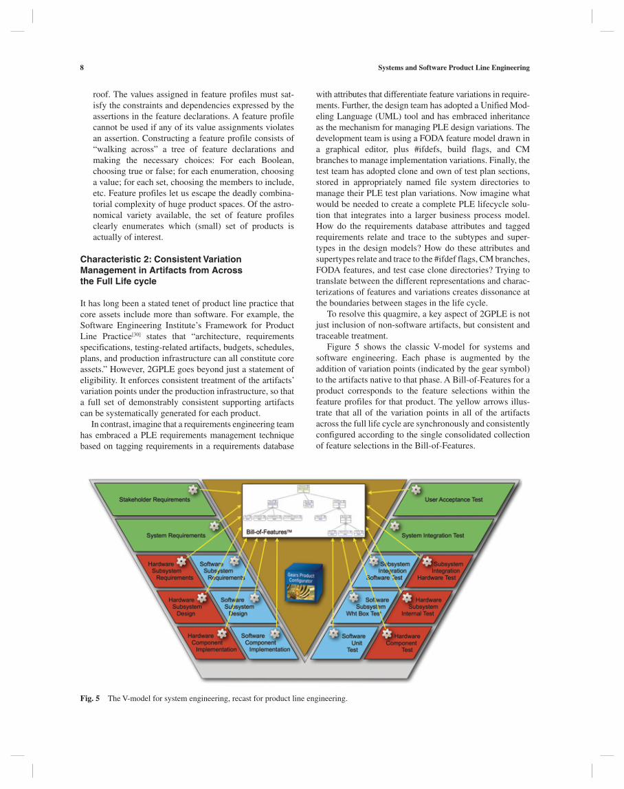
Figure 5 shows the classic V-model for systems and software engineering. Each phase is augmented by the addition of variation points (indicated by the gear symbol) to the artifacts native to that phase. A Bill-of-Features for a product corresponds to the feature selections within the feature profiles for that product. The yellow arrows illus-trate that all of the variation points in all of the artifacts across the full life cycle are synchronously and consistently configured according to the single consolidated collection of feature selections in the Bill-of-Features.
roof. The values assigned in feature profiles must sat-isfy the constraints and dependencies expressed by the assertions in the feature declarations. A feature profile cannot be used if any of its value assignments violates an assertion. Constructing a feature profile consists of “walking across” a tree of feature declarations and making the necessary choices: For each Boolean, choosing true or false; for each enumeration, choosing a value; for each set, choosing the members to include, etc. Feature profiles let us escape the deadly combina-torial complexity of huge product spaces. Of the astro-nomical variety available, the set of feature profiles clearly enumerates which (small) set of products is actually of interest.
Characteristic 2: Consistent Variation Management in Artifacts from Across the Full Life cycle
It has long been a stated tenet of product line practice that core assets include more than software. For example, the Software Engineering Institute’s Framework for Product Line Practice[30] states that “architecture, requirements specifications, testing-related artifacts, budgets, schedules, plans, and production infrastructure can all constitute core assets.” However, 2GPLE goes beyond just a statement of eligibility. It enforces consistent treatment of the artifacts’ variation points under the production infrastructure, so that a full set of demonstrably consistent supporting artifacts can be systematically generated for each product.
In contrast, imagine that a requirements engineering team has embraced a PLE requirements management technique based on tagging requirements in a requirements database
Fig. 5 The V-model for system engineering, recast for product line engineering.

Systems and Software Product Line Engineering 9
Under the factory paradigm of Fig. 3, any defects are fixed in the shared assets, not the products. The affected products will then be regenerated.
Figure 6 is the conceptual roadmap satisfying require-ment R2 under the 2GPLE CM approach. Figure 6 shows the following information:
● A number of shared PLE assets are arrayed down the left-hand side, from various lifecycle phases. Each asset (shown notionally in the figure as modules, pack-ages, components, and test suites) undergoes evolution-ary change; its evolutionary trajectory extends to the right. (For simplicity, although each individual asset is versioned, the chart does not show version numbers.)
● The bottom shows the products in the product line. (For simplicity, only three are shown.) Each product goes through various phases, such as alpha release, beta release, and public release.
● Across the top are several temporal contexts. A tempo-ral context is a vector of assets and the version of each that was used to build a product.
For example, Fig. 6 shows that the Beta version of Product A is built using Temporal Context 5.7. To see what a temporal context comprises, follow its colored line (light blue for Tem-poral Context 5.7) as it zigzags down through the core asset versions to see what versions of what core assets it touches. Figure 6 shows that Temporal Context 5.7 comprises
● the second version of Module 1; ● the second version of Module 2; ● the third version of Module 3;
Characteristic 3: CM that Maintains Assets, Not Products or Asset Instantiations
CM for a product line must satisfy (among others) the fol-lowing two requirements:
● R1: Ensure that no product is created using assets that are temporally incompatible with each other or incor-rect for use in any automatically configured product instance. This establishes and maintains the integrity of the products over time and throughout the engineering life cycle as the assets evolve from version to version.
● R2: Allow the rapid reconstruction of any product ver-sion that may have been built using various versions of the PLE assets and development/operating environ-ment. This capability is essential for rapid response to and remediation of any anomalies that arise in the field.
The most important aspect of CM in 2GPLE is that the full superset of available PLE assets (and not the individual products or systems) are managed under CM. A new ver-sion of a product is not derived from a previous version of the same product, but from the shared superset of PLE assets themselves.
Previous approaches to CM for product lines have adopted a “multidimensional” approach,[30] claiming that CM for product lines requires CM for core assets and CM for products and also stating that “CM for product lines is therefore more complex than it is for single systems.”[34] In fact, a key tenet of 2GPLE is to reduce the complexity of product line CM to that for single products, and much less than that for a suite of separately managed products.[2]
Fig. 6 Temporal contexts in multi-baseline management.
10 Systems and Software Product Line Engineering
parent–child relationship for product lines that typically mirrors the system–subsystem decomposition in the vehicle architecture. Product line features can be partitioned, encap-sulated, and scoped within the primary subsystems that real-ize the features. Features can also be shared among product lines by establishing an import relationship, which is crucial for establishing feature constraints and asset variation points among interrelated subsystems (e.g., a high-end flavor of cruise control that slows the car if there is traffic ahead requires a flavor of the braking system that supports braking via software command).
Characteristic 5: Industrial Strength Automation
The last ingredient in 2GPLE is a configurator like the one shown in Fig. 3, employed to maintain configurations and translate feature profiles into assets with their variation points exercised in prescribed ways.
Previous approaches from 1GPLE have always made allowances for automation, but large-scale PLE demands it. For one thing, the complexities of modern product lines are growing to astronomical proportions. For example, in a product line under way at General Motors, the feature space is so complex that the number of possible variations vastly exceeds the number of atoms in the visible universe (http://en.wikipedia.org/wiki/Observable_universe).[31]
The tooling needs to be able to support the construction and management of feature models (including feature dec-larations, assertions, and profiles), assets, and variation points; support hierarchical production lines; and represent the logic that maps from feature choices to asset instances. Further, it needs to either provide version control for the models and artifacts or (even better) work seamlessly on top of the user’s own choice of change management system.
A major requirement for the tooling is that it supports the specification and selection of variation in assets and arti-facts from across the entire spectrum of the product life cycle. This means that the tool will have to support variation in, for example, DOORS requirements modules, Microsoft Word documents and Excel spreadsheets, build files for Make or Ant, Rhapsody UML models, and many more.
There are fundamentally three ways to achieve variation in an asset, depending on what you know about the digital representation of the associated artifact:
● The representation of the artifact is proprietary and closed, or editors for it are not available or are impracti-cal. For example, if our products include a picture that is different from product to product, some of our arti-facts may be GIF or JPG files. To achieve variation, the variation point can simply choose from a selection of alternative variants, using each one as is, as opposed to trying to change the picture by editing the image stored in a one-size-fits-all picture file.
● The representation of the artifact is “open,” so that you can change it using an available open market tool. For
● the first version of Package 4; ● the third version of Package 5; ● the third version of Package 6; and so forth.
Where temporal context lines intersect, it means that two or more temporal contexts share the same version of an asset. For example, Temporal Contexts 3.0, 4.2, and 5.7 all use the first version of Package 4.
Characteristic 4: Product Lines Across Organizational Boundaries
Organizations, even small ones, often have separate divi-sions at work to support their product line. Large organiza-tions almost certainly do. These divisions may be geographically or organizationally isolated from each other. In this case, it is impractical to expect everyone to work on the same feature model, the same set of shared assets, and so forth. Certainly, having one global collection of feature declarations for an entire production line is impractical when features may number in hundreds or even thousands. Large feature sets engender intractable and incomprehen-sible combinatorics. Subsystem engineers have no interest or need to see all of the feature diversity in other subsys-tems. For example, engineers for an automotive transmis-sion system do not need to see feature abstractions that capture the diversity in the entertainment or GPS navigation system. It makes no sense to comingle them.
It makes much more sense to modularize the feature model in a way that corresponds to the organizational struc-ture of the enterprise. Although these structures can change over time,[33] they make an excellent starting point and let the organization begin to adopt PLE using familiar units.
For example, an automotive vehicle is composed from combinations of dozens of subsystems, all the way from the engine and transmission down to the subsystems that defog the mirrors and heat the driver’s seat. Each of these subsystems has features of its own, which allow a vehicle team to pick and choose in order to define a car. In this way, an automobile (like many complex systems in product lines) is more like a system of systems,[35] which is man-aged as a product line of product lines.
Each of these units represents a domain, by which we mean a body of knowledge.[20] These pockets of deep knowledge are often part of the fabric of the company. In a 2GPLE context, the specialized knowledge becomes knowledge about the feature variations that are possible, and the result is a number of product lines that each con-tributes instances to the overall product. At every level, the same small and elegant set of concepts work to capture the inherent variation. This lets engineers work largely inde-pendently within the confines of their own organizational units and domain expertise.
A hierarchical production line constitutes an architec-ture-like construct, in that there are interfaces and relation-ships among the nested product lines. There is the

Systems and Software Product Line Engineering 11
cycle of each product (vertical axis), evolving the portfolio over time (horizontal axis), and managing the plurality of products (outward-pointing axis). To be a viable paradigm, 2GPLE has to be able to handle each of these “dimen-sions.” Here is how it does:
● The multiphase (vertical) axis of Fig. 7 deals with the usual product engineering lifecycle concerns, such as requirements engineering, architecture and design, implementation, and test, plus the traceability for inter-dependency among the phases. The 2GPLE character-istic of consistent variation management in artifacts from across the life cycle (See the section on “Charac-teristic 2: Consistent Variation Management in Artifacts from across the Full Life Cycle.” ) supports product line diversity through variation points in all assets across the full life cycle.
● The multi-baseline axis of Fig. 7 deals with the usual temporal concerns of product engineering, such as ver-sion, configuration, and change management. The 2GPLE characteristic of CM that maintains assets and not products (see the section on Characteristic 3: CM that Maintains Assets, Not Products or Asset Instantia-tions) supports asset evolution for all assets, without having to independently manage evolution of each of the products in a product line.
● The multi-product axis of Fig. 7, of course, deals directly with the PLE concerns not supported by con-ventional product-centric engineering. The 2GPLE characteristics of features as the lingua franca of varia-tion (See the section on “Characteristic 1: Features as the Lingua Franca to Express Product Differences across the Life Cycle.”), CM that maintains assets and not products (See the section on “Characteristic 3: CM That Maintains Assets, Not Products or Asset Instantia-tions.”), product lines across organizational boundaries (See the section on “Characteristic 4: Product Lines across Organizational Boundaries.”), and industrial
example, artifacts stored as simple text files may be transformed by simple word or line substitution. Arti-facts that are Microsoft Word documents stored in Office Open XML format can be transformed by third-party tools. In this case, the variation point operates by transforming a single variant, transforming it appropri-ately for each product being built.
● The representation of the artifact is proprietary, but the owning organization offers a business relationship to allow your tool to edit their artifacts. Suppose your requirements are stored in DOORS, using hundreds and hundreds of DOORS requirements objects. The represen-tation of those objects is proprietary, but using the strat-egy in the first bullet is out of the question: Swapping in and out whole requirements documents that each differs by just a little bit is untenable. It would be much better to make an arrangement with the vendor (IBM Rational in this case) so that you can write a piece of software that can insert and operate on variation points throughout the DOORS representation of a body of requirements.
This adds another requirement to the product line engi-neering automation engine that does not come immediately to mind: does its proprietor have the necessary business relationships to support variation in the third category? This property is essential for the property of 2GPLE we described earlier: support for variation in shared assets originating from across the entire life cycle.
First-generation approaches always discuss the need for automation; second-generation approaches require it. Fur-ther, they do not just require technical proficiency from the tool but business proficiency from the tool’s proprietor.
HOW 2GPLE HANDLES TRADITIONAL PORTFOLIO ENGINEERING CONCERNS
Organizations building a portfolio of products have to deal with the concerns illustrated in Fig. 7: managing the life
AQ1
Fig. 7 Synchronous concerns of 2GPLE.
12 Systems and Software Product Line Engineering
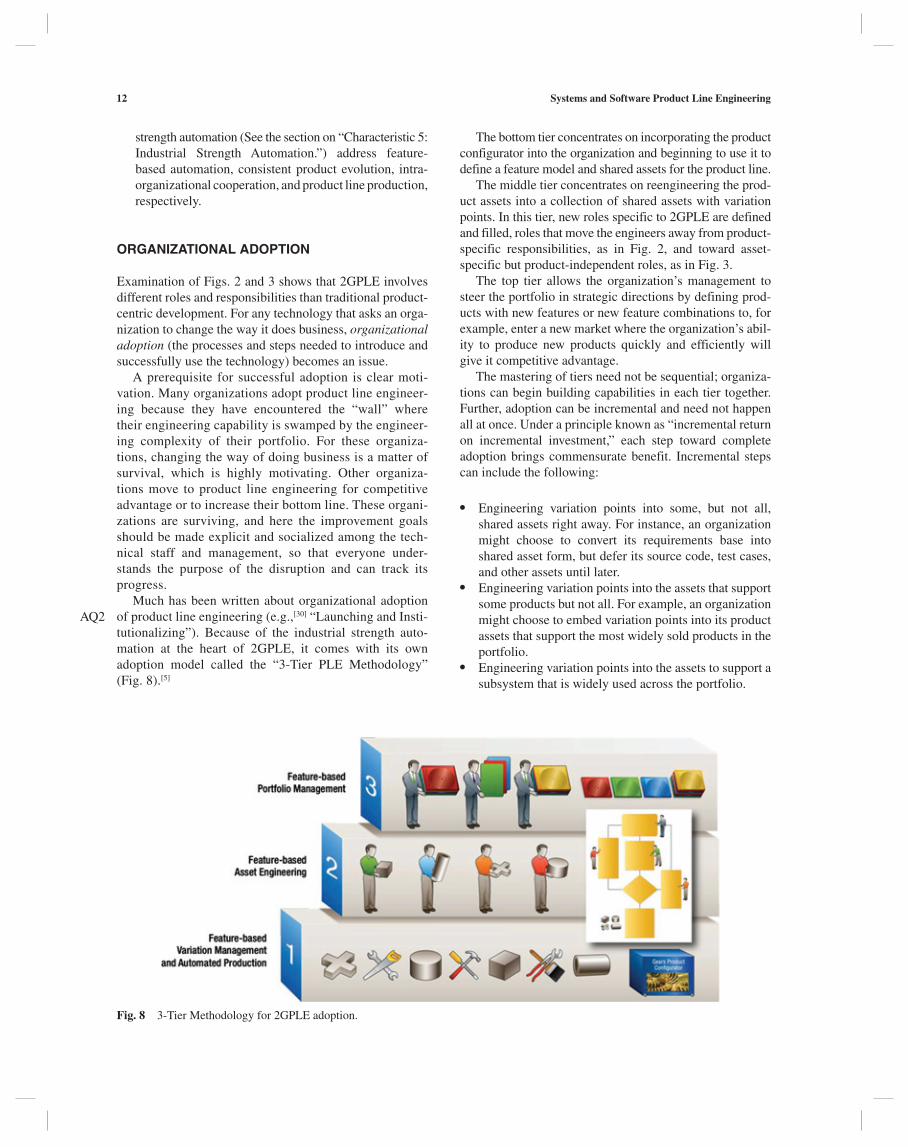
The bottom tier concentrates on incorporating the product configurator into the organization and beginning to use it to define a feature model and shared assets for the product line.
The middle tier concentrates on reengineering the prod-uct assets into a collection of shared assets with variation points. In this tier, new roles specific to 2GPLE are defined and filled, roles that move the engineers away from product-specific responsibilities, as in Fig. 2, and toward asset- specific but product-independent roles, as in Fig. 3.
The top tier allows the organization’s management to steer the portfolio in strategic directions by defining prod-ucts with new features or new feature combinations to, for example, enter a new market where the organization’s abil-ity to produce new products quickly and efficiently will give it competitive advantage.
The mastering of tiers need not be sequential; organiza-tions can begin building capabilities in each tier together. Further, adoption can be incremental and need not happen all at once. Under a principle known as “incremental return on incremental investment,” each step toward complete adoption brings commensurate benefit. Incremental steps can include the following:
● Engineering variation points into some, but not all, shared assets right away. For instance, an organization might choose to convert its requirements base into shared asset form, but defer its source code, test cases, and other assets until later.
● Engineering variation points into the assets that support some products but not all. For example, an organization might choose to embed variation points into its product assets that support the most widely sold products in the portfolio.
● Engineering variation points into the assets to support a subsystem that is widely used across the portfolio.
strength automation (See the section on “Characteristic 5: Industrial Strength Automation.”) address feature-based automation, consistent product evolution, intra-organizational cooperation, and product line production, respectively.
ORGANIZATIONAL ADOPTION
Examination of Figs. 2 and 3 shows that 2GPLE involves different roles and responsibilities than traditional product-centric development. For any technology that asks an orga-nization to change the way it does business, organizational adoption (the processes and steps needed to introduce and successfully use the technology) becomes an issue.
A prerequisite for successful adoption is clear moti-vation. Many organizations adopt product line engineer-ing because they have encountered the “wall” where their engineering capability is swamped by the engineer-ing complexity of their portfolio. For these organiza-tions, changing the way of doing business is a matter of survival, which is highly motivating. Other organiza-tions move to product line engineering for competitive advantage or to increase their bottom line. These organi-zations are surviving, and here the improvement goals should be made explicit and socialized among the tech-nical staff and management, so that everyone under-stands the purpose of the disruption and can track its progress.
Much has been written about organizational adoption of product line engineering (e.g.,[30] “Launching and Insti-tutionalizing”). Because of the industrial strength auto-mation at the heart of 2GPLE, it comes with its own adoption model called the “3-Tier PLE Methodology” (Fig. 8).[5]
AQ2
Fig. 8 3-Tier Methodology for 2GPLE adoption.

Systems and Software Product Line Engineering 13
REFERENCES
1. Schmid, K.; Verlage, M. The economic impact of product line adoption and evolution. IEEE Software 2002, 19, 50–57.
2. Krueger, C. Variation management for software production lines. In Proceedings of the 2nd International Software Product Line Conference, San Diego, California, 2007; 37–48.
3. Bachmann, F.; Clements, P. Variability in Software Product Lines, Technical report CMU/SEI-2005-TR-01, Software Engineering Institute, 2005.
4. Chastek, G.; Donohoe, P.; McGregor, J. Formulation of a Production Strategy for a Software Product Line. Technical note CMU/SEI-2009-TN-025, Software Engineering Insti-tute: 2009.
5. Krueger, C. BigLever software gears and the 3-tiered SPL methodology. In Companion to the 22nd ACM SIGPLAN conference on Object-oriented programming systems and applications companion (OOPSLA “07); ACM: New York, NY, 2007; 844–845. DOI=10.1145/1297846.1297918. http://doi.acm.org/10.1145/1297846.1297918
6. Krueger, C. The Systems and Software Product Line Life-cycle Framework. BigLever Software Technical Report #200805071r3. 2010. http://www.biglever.com/extras/Spl-LifecycleFramework.pdf
7. Beuche, D. Modeling and building software product lines with pure: Variants. In Proceedings of the 15th International Software Product Line Conference, Limerick, Ireland, Sept 08–12, 2008, ACM Press, 2008; SPLC ’08, 358.
8. Jarzabek, S.; Zhang, H. XML-based method and tool for han-dling variant requirements in domain models. In Proceedings of the 5th International Symposium on Requirements Engi-neering, Aug 27–31, 2001; Toronto, Canada, 2001; RE’01, 166–173.
9. Dhungana, D.; Rabiser, R.; Grunbacher, P.; Lehner, K.; Federspiel, C. DOPLER: an adaptable tool suite for product line engineering. In Proceedings of the 11th International Software Product Line Conference, Kyoto, Japan, Sep 10–14, 2007; SPLC ‘07, Second Volume 151–152.
10. Software Engineering Institute. Benefits and costs of a product line. http://www.sei.cmu.edu/productlines/frame_report/benefits.costs.htm
11. Linden, F.J.; van der, S.; Klaus, R.E. Software Product Lines in Action; Springer: New York, 2007.
12. Catalog of Software Product Lines, Software Engineering Institute. http://www.sei.cmu.edu/productlines/casestudies/catalog/index.cfm
13. Jensen, P. Experiences with software product line develop-ment. CrossTalk 2009, 22 (1), 11–14.
14. SPLC Product Line Hall of Fame. http://splc.net/fame.html15. Lanman, J.; Kemper, B.; Rivera, J.; Krueger, C.; Clements, P.
Second generation product line engineering at the U.S. army. SPLC 2012; submitted.
16. Clements, P.; Northrop, L. Software Product Lines: Prac-tices and Patterns; Addison-Wesley: Massachusetts, 2002.
17. Cohen, Ariel, “Russia trails U.S. in pursuit of a fifth-generation jet,” UPI, 14 January 2009, United Press International, 2012. http://www.upi.com/Business_News/Security-Industry/2009/01/14/Russia-trails-US-in-pursuit-of-a-fifth-genera-tion-jet/UPI-35761231951126/
The increments can be as small or large as the organiza-tional context will permit. Full benefit comes with full adoption, but at each step of an incremental approach, the organization will be better off than it was before, and better off than if it chooses to do nothing.
CONCLUSIONS
PLE refers to the disciplined engineering of a portfolio of related products using a common set of shared assets and a common means of production. The products in the portfo-lio are described by the properties they have in common with each other and the variations that set them apart. The products can comprise any combination of 1) software; 2) systems in which software runs; or 3) non-software sys-tems that have software-representable artifacts (such as engineering models or development plans) associated with them.
Product line engineering evolved from the factory para-digm of hard goods manufacturing. Systems and software product line engineering, in turn, evolved from the software product line community, but has grown in scope to include products in which software plays a minor role, if any.
The current best practice product line engineering approach is called 2GPLE, which comprises the following five characteristics:
1. Products are produced through the use of high-end industrial strength automation that configures the shared assets appropriately for each product.
2. All artifacts, software and otherwise, are treated equally. As assets, they are endowed with variation points expressed using the same language constructs, for a consistent representation of the configurability available across all artifacts. This yields consistent and traceable variation management in artifacts across the full engineering life cycle.
3. Features not only describe products and how they dif-fer from each other, but also play the central role in exercising the assets’ variation points. The variation points in an asset are defined by naming the features and feature combinations under which each configu-ration applies. Features become the lingua franca to express product differences in all phases of the life cycle.
4. A simplified CM policy explicitly declines to man-age product versions but only shared asset versions. New versions of products are treated as new products, defined (like any other product) with a combination of features specific to it, and produced by configuring the shared assets accordingly.
5. Feature models with encapsulating constructs facili-tate hierarchical product lines and cooperative feature model development across organizational boundar-ies. This extends the architectural concept of a “sys-tem of systems” to support a “product line of product lines”.

14 Systems and Software Product Line Engineering
28. Software Engineering Institute. Software product lines. www.sei.cmu.edu/productlines
29. Software Product Line Conferences. http://splc.net/history.html
30. Northrop, L.; Clements, P.; Bachmann, F.; Bergey, J.; Chastek, G.; Cohen, S.; Donohoe, P.; Jones, L.; Krut, R.; Little, R.; McGregor, J.; O’Brien, L. A Framework for Soft-ware Product Line Practice Version 5.0. 2009. http://www.sei.cmu.edu/productlines/tools/framework/index.cfm
31. Flores, R.; Krueger, C.; Clements, P. Mega-scale prod-uct line engineering at General Motors. SPLC 2012, 1, 259–268.
32. Lanman, J.; Kemper, B.; Rivera, J.; Krueger, C. Employing the second generation software product-line for live training transformation. In Interservice/Industry Training, Simula-tion, and Education Conference (I/ITSEC), 2011.
33. Bosch, J. Organizing for software product lines. In Proceed-ings of the 3rd International Workshop on Software Archi-tectures for Product Families (IWSAPF-3), Las Palmas de Gran Canaria, Spain, Mar 15–17, 2000; Springer: Berlin, Germany, 2000; 117–134.
34. Software Engineering Institute. A framework for software prod-uct line practice, VERSION 5.0: configuration management. http://www.sei.cmu.edu/productlines/frame_report/config.man.htm
35. Office of the Deputy Under Secretary of Defense for Acqui-sition and Technology. Systems and Software Engineering. Systems Engineering Guide for Systems of Systems, Version 1.0; ODUSD(A&T)SSE: Washington, DC, 2008. http://www.acq.osd.mil/sse/docs/SE-Guide-for-SoS.pdf
36. Riefer, D.J. Practical Software Reuse; Wiley: New York, 1997.
18. Wikipedia, Fifth-generation programming language. http://en.wikipedia.org/wiki/Fifth-generation_programming_ language
19. Parnas, D.L. On the design and development of program families. IEEE Trans. Software Eng 1976, SE-2 (1), 1–9.
20. Kang, K.; Cohen, S.; Hess, J.; Novak, W.; Peterson, A. Fea-ture-Oriented Domain Analysis (FODA) Feasibility Study. (CMU/SEI-90-TR-021, ADA235785); Software Engineer-ing Institute, Carnegie Mellon University: Pittsburgh, PA, 1990.
21. Schaefer, W.; Prieto-Diaz, R.; Matsumoto, M. Eds.; Soft-ware Reusability; Ellis Horwood: New York, 1991.
22. Poulin, J.S. Measuring Software Reuse; Addison Wesley: Massachusetts, 1996.
23. Foreman, J. Product line based software development: Sig-nificant results, future challenges. In Software Technology Conference (STC), 1996.
24. Czarnecki, K.; Eisenbacher, U. Generative Programming: Methods, Tools, and Applications; Addison Wesley: Massa-chusetts, 2000.
25. Weiss, D.M.; Lai, C.T.R. Software Product-Line Engineering: A Family-Based Software Development Process; Addison-Wesley: Massachusetts, 1999.
26. Brownsword, L.; Clements, P. A. Case Study in Successful Prod-uct Line Development (CMU/SEI-96-TR-016, ADA315802); Software Engineering Institute, Carnegie Mellon Univer-sity: Pitts- burgh, PA, 1996; http://www.sei.cmu.edu/publi-cations/documents/96.reports/96.tr.016.html
27. Bergey, J.; Fisher, M.; Jones, L. The DoD Acquisition Envi-ronment and Software Product Lines (CMU/SEI-99-TN-004); Software Engineering Institute, Carnegie Mellon University: Pittsburgh, PA, 1999. http://www.sei.cmu.edu/library/abstracts/reports/99tn004.cfm