systematic development of a multifunctional passenger ... · systematic development of a...
TRANSCRIPT

164
Systematic Development of a Multifunctional Passenger Safety Bar Based on a Reference Project Frame for Student Design Projects
Karl Hain, Christoph Rappl and Josef Süß
Faculty of Mechanical Engineering and Mechatronics DIT - Deggendorf Institute of Technology
94469 Deggendorf, Bavaria, Germany
Walter Steininger Max Streicher GmbH & Co. KG aA
94469 Deggendorf, Germany
Abstract This article describes the systematic development/optimization of a product, i.e. a multifunctional passenger safety bar of a swing seat unit. This project was conducted mainly by students of the faculty of Mechanical Engineering and Mechatronics at the Technical University of Applied Sciences, Deggendorf, Germany in cooperation with an industry partner. The development activities are based on a unified approach, which was worked out for engineering design education and projects. The defined approach, which is introduced and explained at the beginning of the paper, aims at providing undergraduate students a so-called reference frame for conducting engineering design projects which are compulsory within their studies. It provides students a guideline along the course of projects and also a creativity stimulating environment by means of proper embedded techniques for finding, representing, depicting and combining design solutions. The reference frame is based on a long term experience of the authors in conducting projects with students and enterprises as well. Eventually, by taking advantage of the reference frame the systematic development of a passenger safety bar is presented, because it is especially important to exercise theoretical subjects, to verify a theoretical approach and evaluate the methods by the quality of the output. Keywords Engineering Design Education; Product Development; Design Methodology; Project Management; Creativity and Innovation 1. Engineering Design Projects in Education and Reference Frame The challenge of a well-grounded engineering education nowadays is preparing industry ready graduates, that is, to provide students with the skills to master the complexity of products in terms of innovation, invention and problem solving combined with soft skills abilities. This addresses particularly the engineering design education, which should be mainly based on practical studies represented by engineering design projects (Dym et. al. 2005) in order to foster problem-based learning (PBL, Stouffer et. al. 2004). Hereby the effectiveness and efficacy of design projects is a crucial aspect. The prerequisites for instructors are in general (Moor 2001, Hales et al. 2004, Lessard et al. 2007), that students
have less up to none project experience and inappropriate time management, don’t realize all the pieces that are necessary to be done in the course a project, often work on the wrong thing or manage their effort poorly, have also weak work documentation habits, have the tendency to increase effort exponentially as the final deadline approaches.
The commonly agreed goal should be to improve the efficiency of product development processes, to enhance project experience aiming at a better final project and consequently product quality while minimizing instructor interference. Instructors therefore face the question of how to
clarify what are the objectives /expectations of an engineering design project and its deployment, structure and promote the process, deliver and request information in an appropriate manner, develop a feeling of individual responsibility in cooperative learning experiences.
Proceedings of the 2014 International Conference on Industrial Engineering and Operations Management Bali, Indonesia, January 7 – 9, 2014

165
Based on these prerequisites a unified approach in Structuring Projects in Engineering Education and Product Development (SPEED) was designed (Hain and Rappl 2010). The so-called reference frame aims at combining existing design methodologies with an appropriate organisation and management structure (Fig. 1). It is intended not to be too abstract and also not to be too precise in order to support a wide range of design tasks. It is based on many years of design education experience and is supposed to represent a guideline for students and lecturers, because it fits a lot of design projects and shall be used all along the course of a project. At the Technical University of Applied Sciences / Deggendorf, every undergraduate student has to conduct a design project in the Mechanical Engineering course, which amounts to 120 working hours. Therefore, the SPEED structure is designed to be appropriate for a semester long design project in a senior design course in the fourth semester for mechanical engineering and also mechatronic students. These student groups work often closely together which supports the interdisciplinary approaches to design challenges. The projects are terminated to about 16 weeks. Many project ideas emerge from local enterprises thus getting university approaches validated by case studies from industry. An intense cooperation supports the exchange of experiences of scientific personnel, students and practitioners and guarantees customer satisfaction and user feedback. The SPEED structure consists essentially of several meetings and homework stages and determines information about:
involved personnel (P): enterprise representative, supervising lecturer, student design groups project status: five meetings (M1 to M5), four homework stages (H1 to H4) a short agenda of the meetings respectively homework phases required and expected output, that is, produced documents (D1 to D4) a rough time schedule (T); the usage of design checklists (C)
The number of activities is definitely fixed, however, the intervals between are slightly open for change according to project requirements. The standard course is bi-weekly between meetings M1/M2 and M2/M3, and five weeks each between meeting M3/M4 respectively M4/M5. Depending on the complexity of the design task, the number of people involved may vary, whereby the lecturer signs responsible for the elementary team formation activities which are required before the project actually begins.
Figure 1: Structuring Projects in Engineering Education and Product Development (SPEED) The reference frame is based on systematic design approaches, which have a long tradition in Mechanical Engineering. The theories have been worked out and outlined in literature and publications (Suh 1990, VDI-Guideline 2221-1993, Pahl and Beitz 2007). Within specific design stages several aids and methods are applicable and

166
recommended to incorporate into the design process. To master the stages within the reference frame, students are provided with checklists, which describe fundamental design techniques such as the preparation of function structures, morphological matrices, classification schemes, compatibility matrices. Figure 2 shows in principle the structure of relevant documents, which have to be produced along the course of a project.
Figure 2: Project steps and produced documents (see “Documents” in Fig. 1)
Additionally, the complementary use of TRIZ techniques is intended (Fig. 3), whose applicability usually depends on the stage of the project. The inventive problem solving method TRIZ (Teorija Reŝenija Isobretatelskih Zadaĉ) (Orloff 2003) was developed by analyzing thousands of patents thus developing knowledge of different kinds. The key TRIZ concepts are ideality, contradictions and means of overcoming them, substance field analysis, laws of system evolution and a knowledge base of physical effects. Forty inventive principles, which serve as abstract heuristics, were also identified and confirmed through repetition in multiple cases. By following the steps of SPEED students in general are confronted with a lot of alternatives, variants and solution paths, which have to be analyzed, and several authors (Eder 1996, Ogot and Okudan 2006, Lindemann 2011) point out, creativity can result from a systematic approach, increasing the likelihood of obtaining a “best” solution, and therefore makes engineering design fully learnable.
Figure 3: Exemplified TRIZ methods for initial and subsequent design stages (left) and contradiction matrix (right)

167
2. Case Study: Development of a Passenger Safety Bar 2.1 Problem Analysis and Requirements Based on this proposed reference frame several projects have been conducted in the past (Hain et al. 2010), which put theory into practice, and one of these projects is supposed to be presented in the following. Hereby the project members were as follows: 1 enterprise representative, 1 lecturer, 2 students (mechanical engineering), which were responsible for the development of the whole mechanics and 1 mechatronic student, who was responsible for the selection of actuators and sensors and their integration. This paper emphasizes especially the development of the mechanical parts. The presented project aims at the improvement and optimization of a passenger retaining safety bar used for the seats of amusement rides with counterweight (Model “Star Shape”, see Fig. 3, upper). These rides can usually be seen in fairgrounds and amusement parks. The seat units are located on six bars opposite to the counterweight having five seats placed side by side on each bar, therefore, their number amounts to thirty. In the past several problems with the mechanical parts (cracks) due to acceleration and momentum forces, and also with the pneumatical power sypply (drop outs) occurred causing expensive maintenance, services and finally shutdown. The basic requirements can be stated as follows:
Reduction in weight respectively displacement of the seat mass center closer to the base plate, therefore minimization of prevailing stress caused by weight
Simplification, e.g. possibly fewer actuators necessary or usage of simple respectively standard parts Reliable energy supply, e.g. electrical energy instead of pneumatical energy
After initially analyzing the prevailing operation modes (Fig. 4, lower right) the conceived functionality and essential constraints were collected in a specification list (Fig. 4, lower left). The technical regulations which are laid down in “Fairground and amusement park machinery and structures – Safety” (DIN EN 13814-2004) are to be considered.
Figure 4: Passenger seat of “Star Shape” (upper) and essential requirements and functional analysis (lower)

168
2.2 Search for Solutions Based on the elaborated specifications list an abstraction and overall problem formulation was aspired by omitting requirements that have no direct bearing on the function. In this phase especially the TRIZ methods Ideal Final Result (IFR), Operator Material/Time/Size/Cost (MTSC), Smart Little People (SLP), Anticipatory Failure Determination (AFD) were applied (Fig. 3). These methods represent quite an abstract and inventive approach to problem solving with the prerequisite that not all constraints have to be taken strictly into account, e.g. energy supply, geometric limitations, budget demands etc. By regarding this aspect, a broad vision of the problem is permitted and the predetermined ways of conventional thinking are avoided. The additional usage of the method Use Resources (UR) guarantees to reason about available and useful facilities and capabilities. Also the Substance-Field-Analysis (SFA) is considered at this stage. An aspired output within the start-up meeting was the definition of an ideal solution from which an abstract function and furthermore sub-functions can be derived afterwards. Some excerpts are listed in the following: Operator (+/-) MTSC (Material, time, size, cost): (+) Maximum of MTSZ available, e.g. a direct torque drive with integrated brakes and position sensors; (-) Avoid the necessity of the facility so that it is not required anymore, e.g. passengers get equipped with a magnetic plate on their back and pulled tight by a magnetic field from the backrest of the seat; also a hook, clamp, zip fastener or hook and loop fastener could be employed; passengers slide into a body shaped form; passengers get seated and pushed against a fixed bar etc. AFD (Anticipatory Failure Determination): How causing the system to fail? Safety locking system or safety relevant parts get easily worn or are prone to failure while operated; no redundancy present in case of safety parts failure; safety parts are freely accessible and provide the opportunity for fiddling. SLP (Smart little people): How would smart little people solve the problem? For smart little people (dwarfs) this task would be a real challenge. In order to get assistance they would have to apply some sort of force enhancing effects like levers (one-sided, two-sided, knee-lever etc.), keys, gears, hydraulics, pneumatics, electrical appliances; they would have to reason about design strategies like symmetry, asymmetry, equipotentiality and probably counterweights. Smart little people would probably install all necessary actuators and mechanism near to the base plate (mass concentration) in order to facilitate mounting, operation and service of parts and components. Use Resources (UR): All objects that could potentially be useful to achieve the ideal final result, e.g. the basic structural parts of the existing seat design, seat components and connections between them; shape of objects (protrusions, hollow spaces); types of available energy, actuators, materials and tools; existing production facilities. Substance Field Analysis (SFA): No relevant output was created using this technique. IFR (Ideal Final Result): Provide multifunctional passenger safety bar. Taking the IFR as the guiding project title the subsequent brainstorming session strived at the identification of sub-functions and their interoperability depicted in a functional structure (Fig. 5).
Figure 5: Functional structure with input/output and flow of energy and information A function structure allows a clear definition of existing sub-systems or of those to be newly developed, so that they can be dealt with separately, thus facilitating the subsequent search for solutions. Additionally, a defined sub-function structure serves as a starting point for the creation of further variants by breaking down or combining elements,

169
change the arrangements / type of switching / shifts in the system boundary etc. Setting up a function structure means identifying functional, that is physical and/or logical relationships among elements considering the following:
It should be kept as simple and unambiguous as possible, so as to lead to simple and economical solutions. It is advisable to aim at the combination of functions in order to obtain integrated function carriers. The division into decreasing complexity must be continued until the search for a solution seems promising.
It shall be annotated, that a functional decomposition depends to some extent on the mode of operation of solutions, i.e. physical assumptions of imaginable designs.Taking these guidelines into account the main function was decomposed into 6 individual sub-functions and logically arranged by the use of block diagrams. The relevant input/output flow of energy, material and signals is also indicated. In this case electrical respectively manual energy is provided and incoming and outgoing signals control the whole operation process. Based on the functional structure a morphological matrix (Fig. 6) was developed as a guiding scheme for the overall task. This sort of scheme enumerates all possible solutions for enlisted sub-functions. Their subsequent combinations result in overall solutions satisfying the overall task. At first all sub-functions were analyzed with respect to their anticipated importance. For the sub-functions “1” and “2” standard solutions could be found, which were directly inserted. Some specific sub-functions required a more intense examination. Solutions for sub-function “2.1” were generated through another brainstorming session and included afterwards. The sub-function “2.3” and “3” were omitted at first, because they depend strongly on the embodiment design of the other functions. Sub-function “2.3” can for example be conceived as a simple locking bolt or latch, sub-function “3” as one or more specific tools to release the locking mechanism in order to allow a safe opening of the bar in case of emergency.
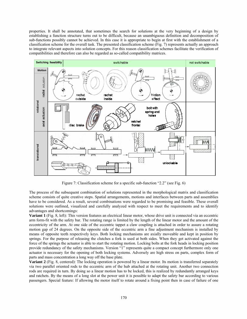
Figure 6: Morphological matrix containing solutions for specific sub-functions For the depiction of solutions for sub-function “2.2” even another separate scheme, a so-called classification scheme, was worked out (Fig. 7). In order to record conceived solutions which are at first usually a rough and unsystematic collection of basic ideas, this scheme allows the generation of further ones. The typically two-dimensional scheme consists of rows and columns of parameters used as classifying criteria which are often derived from properties that basic ideas are characterized by. The classifying criteria for the columns were determined to be “Switching feasibility”. The row criterion “Motion” is represented by the mode “rotational/translational”, whereby “rotational” was extended by a further breakdown into “axial/radial actuation”. First basic ideas were integrated into this scheme and new ideas produced by means of systematic variation, i.e. usually by the variation of type, shape, position, size, number. The great benefit on the one hand is that the search for further solutions was stimulated in various directions and on the other hand the identification and combination of essential solution characteristics and properties was facilitated. It is advisable to express solutions by rough sketches, which reveal the most important characteristics and
170
properties. It shall be annotated, that sometimes the search for solutions at the very beginning of a design by establishing a function structure turns out to be difficult, because an unambiguous definition and decomposition of sub-functions possibly cannot be achieved. In this case it is appropriate to begin at first with the establishment of a classification scheme for the overall task. The presented classification scheme (Fig. 7) represents actually an approach to integrate relevant aspects into solution concepts. For this reason classification schemes facilitate the verification of compatibilities and therefore can also be regarded as so-called compatibility matrices.
Figure 7: Classification scheme for a specific sub-function “2.2” (see Fig. 6) The process of the subsequent combination of solutions represented in the morphological matrix and classification scheme consists of quite creative steps. Spatial arrangements, motions and interfaces between parts and assemblies have to be considered. As a result, several combinations were regarded to be promising and feasible. These overall solutions were outlined, visualized and carefully analyzed with respect to meet the requirements and to identify advantages and shortcomings: Variant 1 (Fig. 8, left): This version features an electrical linear motor, whose drive unit is connected via an eccentric arm form-fit with the safety bar. The rotating range is limited by the length of the linear motor and the amount of the eccentricity of the arm. At one side of the eccentric tappet a claw coupling is attached in order to assure a rotating motion gap of 24 degrees. On the opposite side of the eccentric arm a fine adjustment mechanism is installed by means of opposite teeth respectively keys. Both locking mechanisms are axially moveable and kept in position by springs. For the purpose of releasing the clutches a fork is used at both sides. When they get activated against the force of the springs the actuator is able to start the rotating motion. Locking bolts at the fork heads in locking position provide redundancy of the safety mechanisms. Version “1” represents quite a compact concept furthermore only one actuator is necessary for the opening of both locking systems. Adversely are high stress on parts, complex form of parts and mass concentration a long way off the base plate. Variant 2 (Fig. 8, centered): The locking operation is powered by a linear motor. Its motion is transferred separately via two parallel oriented rods to the eccentric arm of the hub attached at the rotating unit. Another two connection rods are required in turn. By doing so a linear motion has to be locked, this is realized by redundantly arranged keys and ratchets. By the means of a long slot at the power unit it is possible to adapt the safety bar according to various passengers. Special feature: If allowing the motor itself to rotate around a fixing point then in case of failure of one

171
locking mechanism opening of the safety bar is prevented, because no energy is transferred anymore. Further advantages are less stress on parts and mass concentration close to the base plate. Variant 3 (Fig. 8, right): The rotating motion is initiated by an e-motor. It drives via a one-stage gear two parallel discs, each equipped with keys and ratchets. Two additional rods provide the connection to the hub of the safety bar. With this version weight balance can be achieved and improved. However, a failure within one safety locking system is not recognized within driving cycles. Variant 4 (Fig. 8, centered): A linear positioning cylinder serves as an actuator. Its translational motion is transferred into a rotational one by means of eccentric arranged rods on parallel discs. Each of these discs is equipped with redundantly arranged keys and ratchets and also gears-wheels, which again transform the rotational motion into a linear one by means of gear racks. The disc brakes allow a continuously adjustment to passengers. With this version weight concentration near to the base plate is feasible. However, the force-fit clamping of the disc brakes represents a quite risky solution taking safety-related aspects under consideration. Variant 5 (Fig. 8, right): A rotating motion is initiated by an e-motor, which has effect on two parallel arranged gear-wheels and shafts. Each shaft features parallel discs and redundantly installed locking systems. Worm gears at the shaft extensions drive the corresponding gear-wheels of the safety bar. Advantages are the self-locking of the worm gears, whereas fine adjustment of the safety bar is not possible. Sensors are required to control end positions.
Figure 8: Five design concepts respectively variants for the overall task After an evaluation process which considered especially functionality (robustness, steadiness, weight balance, wear safety, system redundancy) and costs (number, simplicity and mountability of components) the concept variant no. 2 was considered worth for embodiment design and further detailing.
2.3 Embodiment Design of Retaining Safety Bar The overall final solution was worked out and detailed. This required the development of parts and sub-assemblies, their spatial arrangement, the selection of purchased parts and the conduction of calculations and simulations. In the following some characteristics of the eventually developed multifunctional safety bar are described (Fig. 10): The energy respectively linear motion from the actuator (1) is transformed directly to the connecting rod (2). On both sides of the rod two independently operating push/pull rods (3) are attached which are guided by T-slots to avoid bending. Both push/pull rods are provided with several keyways and ratchets, i.e. each of them carries one operation locking mechanism (4) and also one safety locking mechanism (5). Therefore, redundancy is achieved by two independently working locking mechanisms. If the bar brakes, all locking mechanisms are still in service. For the purpose of a more accurate individual adjustment the keyways are arranged in an offset pattern. If one operation locking mechanism fails, the bar will rotate half the way of one key and be locked again by the redundant mechanism. Additionally, to compensate the failure of the second operation ratchet, safety ratchets are installed on both sides. These keep the safety bar in a minimum closing position. In order to release the safety bar completely after the
172
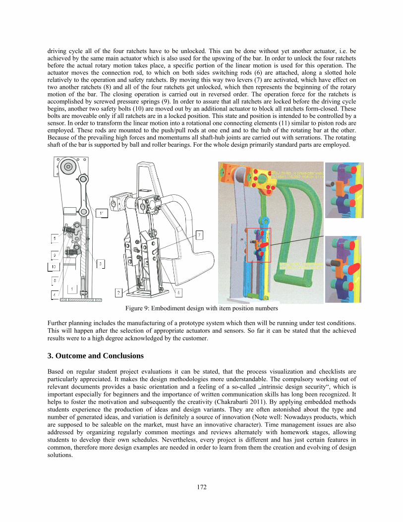
driving cycle all of the four ratchets have to be unlocked. This can be done without yet another actuator, i.e. be achieved by the same main actuator which is also used for the upswing of the bar. In order to unlock the four ratchets before the actual rotary motion takes place, a specific portion of the linear motion is used for this operation. The actuator moves the connection rod, to which on both sides switching rods (6) are attached, along a slotted hole relatively to the operation and safety ratchets. By moving this way two levers (7) are activated, which have effect on two another ratchets (8) and all of the four ratchets get unlocked, which then represents the beginning of the rotary motion of the bar. The closing operation is carried out in reversed order. The operation force for the ratchets is accomplished by screwed pressure springs (9). In order to assure that all ratchets are locked before the driving cycle begins, another two safety bolts (10) are moved out by an additional actuator to block all ratchets form-closed. These bolts are moveable only if all ratchets are in a locked position. This state and position is intended to be controlled by a sensor. In order to transform the linear motion into a rotational one connecting elements (11) similar to piston rods are employed. These rods are mounted to the push/pull rods at one end and to the hub of the rotating bar at the other. Because of the prevailing high forces and momentums all shaft-hub joints are carried out with serrations. The rotating shaft of the bar is supported by ball and roller bearings. For the whole design primarily standard parts are employed.
Figure 9: Embodiment design with item position numbers
Further planning includes the manufacturing of a prototype system which then will be running under test conditions. This will happen after the selection of appropriate actuators and sensors. So far it can be stated that the achieved results were to a high degree acknowledged by the customer. 3. Outcome and Conclusions Based on regular student project evaluations it can be stated, that the process visualization and checklists are particularly appreciated. It makes the design methodologies more understandable. The compulsory working out of relevant documents provides a basic orientation and a feeling of a so-called „intrinsic design security“, which is important especially for beginners and the importance of written communication skills has long been recognized. It helps to foster the motivation and subsequently the creativity (Chakrabarti 2011). By applying embedded methods students experience the production of ideas and design variants. They are often astonished about the type and number of generated ideas, and variation is definitely a source of innovation (Note well: Nowadays products, which are supposed to be saleable on the market, must have an innovative character). Time management issues are also addressed by organizing regularly common meetings and reviews alternately with homework stages, allowing students to develop their own schedules. Nevertheless, every project is different and has just certain features in common, therefore more design examples are needed in order to learn from them the creation and evolving of design solutions.

173
Acknowledgements This work was supported by the company Max Streicher GmbH & Co. KG aA, 94469 Deggendorf, Germany. References Chakrabarti, A., Motivation as a Major Direction for Design Creativity Research, Design Creativity 2010, Eds.
Toshiharu Taura, Yukari Nagai, London, Springer-Verlag, ISBN 978-0-85729-223-0, 2011. DIN EN 13814, Normenausschuss Bauwesen (NA Bau), Fliegende Bauten und Anlagen für Veranstaltungsplätze
und Vergnügungsparks - Sicherheit (European Standard: Fairground and amusement park machinery and structures - Safety), ICS 91.040.99, December 2004.
Dym, C.L., Agogino, A.M., Eris, O., Frey, D.D., and Leifer, L.J., Engineering Design Thinking, Teaching, and Learning, Journal of Engineering Education (JEE), American Society for Engineering Education (ASEE), Wiley Online Library, Issue: January 2005.
Eder, W.E., Viewpoint – Engineering design art, science and relationships, Design Studies, vol. 16(1): pp.117-127, 1996.
Hain, K., Rappl, C., Reitberger, S., Huber, S. (2010): Development of an Innovative Tool Rack by Providing a Creativity Frame for Educational Engineering Projects, 3rd International Conference on Science & Technology, Pulau Penang: Proceedings of ICSTIE-2010, ISBN 978-983-42204-4-0, 2010.
Hain, K., and Rappl, C., Engineering Design Projects in Education: A Reference Frame Based on Design Methodology, Proceedings of International Technology, Education and Development Conference INTED-2010, Valencia, Spain, ISBN 978-84-613-5538-9, 2010.
Hales, Crispin, Gooch, and Shayne, Managing Engineering Design, Springer-Verlag, 2nd Edition, London, ISBN: 978-185233-8039, 2004.
Lessard, C., and Lessard, J., Project Management for Engineering Design (Synthesis Lectures on Engineering), Morgan & Claypool Publishers, USA, ISBN-10: 1598291742, 2007.
Lindemann, U., Systematic Procedures Supporting Creativity – A Contradiction?, Design Creativity 2010, Eds. Toshiharu Taura and Yukari Nagai, London, Springer-Verlag, ISBN 978-0-85729-223-0, 2011.
Moor, S., et al., Addressing common problems in engineering design projects: A project management approach, Journal of Engineering Education, 2001.
Ogot, M., and Okudan, G.E., Systematic Creativity Methods in Engineering Education: A Learning Styles Perspective, International Journal of Engineering Education (IJEE), Tempus Publications, Great Britain, Vol. 22, No. 3, pp. 566-576, 2006.
Orloff, M. A., Inventive Thinking through TRIZ- A Practical Guide, Berlin-Heidelberg-New York, Springer-Verlag, ISBN 3-540-44018-6, 2003.
Pahl, G., and Beitz, W., Engineering Design – A Systematic Approach, Edited by Ken Wallace, Springer, ISBN: 978-1-84628-318-5 (Print), 978-1-84628-319-2 (Online), 2007.
Stouffer, W.B., Russell, J.S., and Oliva, M.G., Making the Strange Familiar: Creativity and the Future of Engineering Education, Proceedings of the 2004 American Society for Engineering Education Annual Conference & Exposition, Session No. 1615, American Society for Engineering Education, 2004.
Suh, N.P., The principles of design, Oxford Series on Advanced Manufacturing, New York, Oxford, Oxford University Press, ISBN 0-19-504345-6, 1990.
VDI-Guideline 2221, Methodik zum Entwickeln und Konstruieren technischer Systeme und Produkte, VDI-Guideline, Düsseldorf, VDI-Verlag, May 1993.
Biographies Karl Hain is currently a fulltime Professor at the Technical University of Applied Sciences in Deggendorf, Germany. He is study dean of the faculty Mechanical Engineering and Mechatronics. He earned his Diploma (Dipl.-Ing.) in Mechanical Engineering from Technical University Clausthal, Germany and PhD (Dr.-Ing.) in Mechanical Engineering from Technical University of Karlsruhe. He worked several years in industry, e.g. at the company MTU (Motoren- und Turbinen-Union, Friedrichshafen / Germany) as a design engineer and at the company OPEL as a project leader responsible for worldwide data exchange. He has published journal and conference papers. His research interests include engineering design, design methodology, CAD and simulation. Prof. Hain has done several research projects with local companies around Deggendorf, Lower Bavaria. He is former member of the Advisory Board of INTED (International Technology, Education and Development).

174
Christoph Rappl is currently a fulltime Professor at the Technical University of Applied Sciences in Deggendorf, Germany. He is dean of the faculty Mechanical Engineering and Mechatronics. He earned his Diploma (Dipl.-Ing.) in Electrical Engineering from Technical University Berlin, Germany and PhD (Dr.-Ing.) in Process Engineering from Technical University of Berlin. He worked several years in industry at the company Bayer (Automation of Chemical Plants / Germany) as a project engineer. He has published journal and conference papers. His research interests include mechatronic design, automation and control, simulation and embedded systems. Prof. Rappl has done several research projects with local companies around Deggendorf, Lower Bavaria. He is former member of the Advisory Board of INTED (International Technology, Education and Development). Walter Steininger is chief and project designer working for the company STREICHER / Deggendorf / Germany. The STREICHER Group is characterized by technologies and services in the business sectors pipelines and plants, mechanical engineering, civil and structural engineering, raw and construction material etc. Mr. Weinberger is employed in the ZIERER-compartment, i.e. construction of amusement rides for leisure parks and showmen. Josef Süß earned his Diploma (Dipl.-Ing.) from the Technical University of Deggendorf / Germany. He was project leader of the presented project and responsible for the mechanical mechanisms. After his studies he now works in industry as a design engineer.