system v application binary interface sparc...
TRANSCRIPT

SYSTEM VAPPLICATIONBINARY INTERFACE
SPARC ProcessorSupplement
Third Edition

Copyright 1990−1996 The Santa Cruz Operation, Inc. All rights reserved.
Copyright 1990 AT&T. All rights reserved.
No part of this publication may be reproduced, transmitted, stored in a retrieval system, nor translated into any human or computerlanguage, in any form or by any means, electronic, mechanical, magnetic, optical, chemical, manual, or otherwise, without the priorwritten permission of the copyright owner, The Santa Cruz Operation, Inc., 400 Encinal Street, Santa Cruz, California, 95060, USA.Copyright infringement is a serious matter under the United States and foreign Copyright Laws.
Information in this document is subject to change without notice and does not represent a commitment on the part of The SantaCruz Operation, Inc.
SCO UnixWare is commercial computer software and, together with any related documentation, is subject to the restrictions onUS Government use as set forth below. If this procurement is for a DOD agency, the following DFAR Restricted Rights Legendapplies:
RESTRICTED RIGHTS LEGEND: Use, duplication, or disclosure by the Government is subject to restrictions as set forth insubparagraph (c)(1)(ii) of Rights in Technical Data and Computer Software Clause at DFARS 252.227-7013. Contractor/Manufactureris The Santa Cruz Operation, Inc., 400 Encinal Street, Santa Cruz, CA 95060.
If this procurement is for a civilian government agency, this FAR Restricted Rights Legend applies:
RESTRICTED RIGHTS LEGEND: This computer software is submitted with restricted rights under Government Contract No._________ (and Subcontract No. ________, if appropriate). It may not be used, reproduced, or disclosed by the Government exceptas provided in paragraph (g)(3)(i) of FAR Clause 52.227-14 alt III or as otherwise expressly stated in the contract.Contractor/Manufacturer is The Santa Cruz Operation, Inc., 400 Encinal Street, Santa Cruz, CA 95060.
If any copyrighted software accompanies this publication, it is licensed to the End User only for use in strict accordance with the EndUser License Agreement, which should be read carefully before commencing use of the software.
TRADEMARKS
SCO, the SCO logo, The Santa Cruz Operation, and UnixWare are trademarks or registered trademarks of The Santa Cruz Operation,Inc. in the USA and other countries. SPARC is a registered trademark of SPARC International, Inc. UNIX is a registered trademark inthe USA and other countries, licensed exclusively through X/Open Company Limited. Motif is a trademark of the Open SoftwareFoundation, Inc. NeWS is a registered trademark of Sun Microsystems, Inc. X11 and X Window System are trademarks ofMassachusetts Institute of Technology. All other brand and product names are or may be trademarks of, and are used to identifyproducts or services of, their respective owners.
1

Contents
1 INTRODUCTIONSPARC Processor and the System V ABI 1-1How to Use the SPARC ABI Supplement 1-2
2 SOFTWARE INSTALLATIONSoftware Distribution Formats 2-1
3 LOW-LEVEL SYSTEM INFORMATIONMachine Interface 3-1Function Calling Sequence 3-8Operating System Interface 3-21Coding Examples 3-34
4 OBJECT FILESELF Header 4-1Sections 4-2Relocation 4-3
5 PROGRAM LOADING AND DYNAMIC LINKINGProgram Loading 5-1Dynamic Linking 5-5
6 LIBRARIESSystem Library 6-1System Data Interfaces 6-11
7 DEVELOPMENT ENVIRONMENTDevelopment Commands 7-1Software Packaging Tools 7-2
Table of Contents i

Table of Contents
8 EXECUTION ENVIRONMENTApplication Environment 8-1
IN IndexIndex IN-1
ii SPARC PROCESSOR SUPPLEMENT

Figures and Tables
Figure 3-1: Scalar Types 3-2Figure 3-2: Structure Smaller Than a Word 3-3Figure 3-3: No Padding 3-3Figure 3-4: Internal Padding 3-4Figure 3-5: Internal and Tail Padding 3-4Figure 3-6: u n i o n Allocation 3-4Figure 3-7: Bit-Field Ranges 3-5Figure 3-8: Bit Numbering 3-6Figure 3-9: Left-to-Right Allocation 3-6Figure 3-10: Boundary Alignment 3-6Figure 3-11: Storage Unit Sharing 3-6Figure 3-12: u n i o n Allocation 3-7Figure 3-13: Unnamed Bit-Fields 3-7Figure 3-14: A Function’s Window Registers 3-9Figure 3-15: A Function’s Global Registers 3-10Figure 3-16: Standard Stack Frame 3-11Figure 3-17: Function Prologue 3-12Figure 3-18: Register Windows 3-12Figure 3-19: Integral and Pointer Arguments 3-15Figure 3-20: Floating-Point Arguments 3-16Figure 3-21: Sending Structure, Union, and Quad-Precision Arguments 3-16Figure 3-22: Receiving Structure, Union, and Quad-Precision Arguments 3-17Figure 3-23: Function Epilogue 3-18Figure 3-24: Alternative Function Epilogue 3-18Figure 3-25: Function Epilogue 3-20Figure 3-26: Virtual Address Configuration 3-22Figure 3-27: Hardware Traps and Signals 3-24Figure 3-28: Software Trap Types 3-25Figure 3-29: Declaration for m a i n 3-27Figure 3-30: Processor State Register Fields 3-28Figure 3-31: Floating-Point State Register Fields 3-28Figure 3-32: Initial Process Stack 3-29Figure 3-33: Auxiliary Vector 3-30Figure 3-34: Auxiliary Vector Types, a _ t y p e 3-31Figure 3-35: Example Process Stack 3-33Figure 3-36: Position-Independent Function Prologue 3-36Figure 3-37: Absolute Load and Store 3-37Figure 3-38: Small Model Position-Independent Load and Store 3-38Figure 3-39: Large Model Position-Independent Load and Store 3-39Figure 3-40: Direct Function Call, All Models 3-40Figure 3-41: Absolute Indirect Function Call 3-40Figure 3-42: Small Model Position-Independent Indirect Function Call 3-41Figure 3-43: Large Model Position-Independent Indirect Function Call 3-41Figure 3-44: Branch Instruction, All Models 3-42Figure 3-45: Absolute s w i t c h Code 3-43Figure 3-46: Position-Independent s w i t c h Code 3-43
Table of Contents iii

Table of Contents
Figure 3-47: C Stack Frame 3-44Figure 3-48: Argument Stack Positions 3-45Figure 3-49: Dynamic Stack Allocation 3-47Figure 4-1: SPARC Identification, e _ i d e n t 4-1Figure 4-2: Special Sections 4-2Figure 4-3: Relocatable Fields 4-3Figure 4-4: Relocation Types 4-5Figure 5-1: Executable File 5-1Figure 5-2: Program Header Segments 5-2Figure 5-3: Process Image Segments 5-3Figure 5-4: Example Shared Object Segment Addresses 5-4Figure 5-5: Global Offset Table 5-6Figure 5-6: Procedure Linkage Table Example 5-8Figure 6-1: l i b s y s Support Routines 6-1Figure 6-2: l i b s y s, Global External Data Symbols 6-10Figure 6-3: < a s s e r t . h > 6-11Figure 6-4: < c t y p e . h > 6-12Figure 6-5: < d i r e n t . h > 6-13Figure 6-6: < e r r n o . h > 6-13Figure 6-7: < f c n t l . h > 6-16Figure 6-8: < f l o a t . h > 6-17Figure 6-9: < f m t m s g . h > 6-17Figure 6-10: < f t w . h > 6-18Figure 6-11: < g r p . h > 6-18Figure 6-12: < s y s / i p c . h > 6-19Figure 6-13: < l a n g i n f o . h > 6-19Figure 6-14: < l i m i t s . h > 6-21Figure 6-15: < l o c a l e . h > 6-22Figure 6-16: < m a t h . h > 6-22Figure 6-17: < s y s / m m a n . h > 6-23Figure 6-18: < s y s / m o u n t . h > 6-23Figure 6-19: < s y s / m s g . h > 6-24Figure 6-20: < n e t c o n f i g . h > 6-25Figure 6-21: < n e t d i r . h > 6-26Figure 6-22: < n l _ t y p e s . h > 6-27Figure 6-23: < s y s / p a r a m . h > 6-27Figure 6-24: < p o l l . h > 6-28Figure 6-25: < s y s / p r o c s e t . h > 6-29Figure 6-26: < p w d . h > 6-30Figure 6-27: < s y s / r e s o u r c e . h > 6-30Figure 6-28: < r p c . h > 6-31Figure 6-29: < s e a r c h . h > 6-38Figure 6-30: < s y s / s e m . h > 6-39Figure 6-31: < s e t j m p . h > 6-39Figure 6-32: < s y s / s h m . h > 6-40Figure 6-33: < s i g n a l . h > 6-40Figure 6-34: < s y s / s i g i n f o . h > 6-42Figure 6-35: < s y s / s t a t . h > 6-43Figure 6-36: < s y s / s t a t v f s . h > 6-45Figure 6-37: < s t d a r g . h > 6-45Figure 6-38: < s t d d e f . h > 6-46Figure 6-39: < s t d i o . h > 6-47
iv SPARC PROCESSOR SUPPLEMENT

Table of Contents
Figure 6-40: < s t d l i b . h > 6-48Figure 6-41: < s t r o p t s . h > 6-49Figure 6-42: < t e r m i o s . h > 6-51Figure 6-43: < s y s / t i c l t s . h > 6-55Figure 6-44: < s y s / t i c o t s . h > 6-55Figure 6-45: < s y s / t i c o t s o r d . h > 6-55Figure 6-46: < s y s / t i h d r . h > 6-56Figure 6-47: < s y s / t i m e . h > 6-57Figure 6-48: < s y s / t i m e s . h > 6-58Figure 6-49: < s y s / t i m o d . h > 6-58Figure 6-50: < s y s / t i u s e r . h >, Service Types 6-58Figure 6-51: < t i u s e r . h >, Transport Interface States 6-59Figure 6-52: < s y s / t i u s e r . h >, User-level Events 6-59Figure 6-53: < s y s / t i u s e r . h >, Error Return Values 6-60Figure 6-54: < s y s / t i u s e r . h >, Transport Interface Data Structures 6-60Figure 6-55: < s y s / t i u s e r . h >, Structure Types 6-62Figure 6-56: < s y s / t i u s e r . h >, Fields of Structures 6-62Figure 6-57: < s y s / t i u s e r . h >, Events Bitmasks 6-62Figure 6-58: < s y s / t i u s e r . h >, Flags 6-63Figure 6-59: < s y s / t y p e s . h > 6-63Figure 6-60: < u c o n t e x t . h > 6-64Figure 6-61: < s y s / u i o . h > 6-65Figure 6-62: < u l i m i t . h > 6-65Figure 6-63: < u n i s t d . h > 6-66Figure 6-64: < u t i m e . h > 6-67Figure 6-65: < s y s / u t s n a m e . h > 6-67Figure 6-66: < w a i t . h > 6-68Figure 6-67: < X 1 1 / C o m p o s i t e . h > 6-70Figure 6-68: < X 1 1 / C o n s t r a i n t . h > 6-70Figure 6-69: < X 1 1 / C o r e . h > 6-70Figure 6-70: < X 1 1 / c u r s o r f o n t . h >, Part 1 of 3 6-71Figure 6-71: < X 1 1 / c u r s o r f o n t . h >, Part 2 of 3 6-72Figure 6-72: < X 1 1 / c u r s o r f o n t . h >, Part 3 of 3 6-73Figure 6-73: < X 1 1 / I n t r i n s i c . h >, Part 1 of 6 6-74Figure 6-74: < X 1 1 / I n t r i n s i c . h >, Part 2 of 6 6-75Figure 6-75: < X 1 1 / I n t r i n s i c . h >, Part 3 of 6 6-76Figure 6-76: < X 1 1 / I n t r i n s i c . h >, Part 4 of 6 6-77Figure 6-77: < X 1 1 / I n t r i n s i c . h >, Part 5 of 6 6-78Figure 6-78: < X 1 1 / I n t r i n s i c . h >, Part 6 of 6 6-79Figure 6-79: < X 1 1 / O b j e c t . h > 6-79Figure 6-80: < X 1 1 / R e c t O b j . h > 6-79Figure 6-81: < X 1 1 / S h e l l . h > 6-80Figure 6-82: < X 1 1 / V e n d o r . h > 6-80Figure 6-83: < X 1 1 / X . h >, Part 1 of 12 6-81Figure 6-84: < X 1 1 / X . h >, Part 2 of 12 6-82Figure 6-85: < X 1 1 / X . h >, Part 3 of 12 6-83Figure 6-86: < X 1 1 / X . h >, Part 4 of 12 6-84Figure 6-87: < X 1 1 / X . h >, Part 5 of 12 6-85Figure 6-88: < X 1 1 / X . h >, Part 6 of 12 6-86Figure 6-89: < X 1 1 / X . h >, Part 7 of 12 6-87Figure 6-90: < X 1 1 / X . h >, Part 8 of 12 6-88Figure 6-91: < X 1 1 / X . h >, Part 9 of 12 6-89
Table of Contents v

Table of Contents
Figure 6-92: < X 1 1 / X . h >, Part 10 of 12 6-90Figure 6-93: < X 1 1 / X . h >, Part 11 of 12 6-91Figure 6-94: < X 1 1 / X . h >, Part 12 of 12 6-92Figure 6-95: < X 1 1 / X a t o m . h >, Part 1 of 3 6-93Figure 6-96: < X 1 1 / X a t o m . h >, Part 2 of 3 6-94Figure 6-97: < X 1 1 / X a t o m . h >, Part 3 of 3 6-95Figure 6-98: < X 1 1 / X c m s . h >, Part 1 of 5 6-96Figure 6-99: < X 1 1 / X c m s . h >, Part 2 of 5 6-97Figure 6-100: < X 1 1 / X c m s . h >, Part 3 of 5 6-98Figure 6-101: < X 1 1 / X c m s . h >, Part 4 of 5 6-99Figure 6-102: < X 1 1 / X c m s . h >, Part 5 of 5 6-100Figure 6-103: < X 1 1 / X l i b . h > Part 1 of 27 6-101Figure 6-104: < X 1 1 / X l i b . h > Part 2 of 27 6-101Figure 6-105: < X 1 1 / X l i b . h > Part 3 of 27 6-102Figure 6-106: < X 1 1 / X l i b . h > Part 4 of 27 6-103Figure 6-107: < X 1 1 / X l i b . h > Part 5 of 27 6-104Figure 6-108: < X 1 1 / X l i b . h > Part 6 of 27 6-105Figure 6-109: < X 1 1 / X l i b . h > Part 7 of 27 6-106Figure 6-110: < X 1 1 / X l i b . h > Part 8 of 27 6-107Figure 6-111: < X 1 1 / X l i b . h > Part 9 of 27 6-108Figure 6-112: < X 1 1 / X l i b . h > Part 10 of 27 6-109Figure 6-113: < X 1 1 / X l i b . h > Part 11 of 27 6-110Figure 6-114: < X 1 1 / X l i b . h > Part 12 of 27 6-111Figure 6-115: < X 1 1 / X l i b . h > Part 13 of 27 6-112Figure 6-116: < X 1 1 / X l i b . h > Part 14 of 27 6-113Figure 6-117: < X 1 1 / X l i b . h > Part 15 of 27 6-114Figure 6-118: < X 1 1 / X l i b . h > Part 16 of 27 6-115Figure 6-119: < X 1 1 / X l i b . h > Part 17 of 27 6-116Figure 6-120: < X 1 1 / X l i b . h > Part 18 of 27 6-117Figure 6-121: < X 1 1 / X l i b . h > Part 19 of 27 6-118Figure 6-122: < X 1 1 / X l i b . h > Part 20 of 27 6-119Figure 6-123: < X 1 1 / X l i b . h > Part 21 of 27 6-120Figure 6-124: < X 1 1 / X l i b . h > Part 22 of 27 6-121Figure 6-125: < X 1 1 / X l i b . h > Part 23 of 27 6-122Figure 6-126: < X 1 1 / X l i b . h > Part 24 of 27 6-123Figure 6-127: < X 1 1 / X l i b . h > Part 25 of 27 6-124Figure 6-128: < X 1 1 / X l i b . h > Part 26 of 27 6-125Figure 6-129: < X 1 1 / X l i b . h > Part 27 of 27 6-126Figure 6-130: < X 1 1 / X r e s o u r c e . h >, Part 1 of 2 6-127Figure 6-131: < X 1 1 / X r e s o u r c e . h >, Part 2 of 2 6-128Figure 6-132: < X 1 1 / X u t i l . h >, Part 1 of 5 6-129Figure 6-133: < X 1 1 / X u t i l . h >, Part 2 of 5 6-130Figure 6-134: < X 1 1 / X u t i l . h >, Part 3 of 5 6-131Figure 6-135: < X 1 1 / X u t i l . h >, Part 4 of 5 6-132Figure 6-136: < X 1 1 / X u t i l . h >, Part 5 of 5 6-133Figure 6-137: < n e t i n e t / i n . h > 6-135Figure 6-138: < n e t i n e t / i p . h > 6-135Figure 6-139: < n e t i n e t / t c p . h > 6-135
vi SPARC PROCESSOR SUPPLEMENT

1 INTRODUCTION
SPARC Processor and the System V ABI 1-1
How to Use the SPARC ABI Supplement 1-2Evolution of the ABI Specification 1-2
Table of Contents i

SPARC Processor and the System V ABI
The System V Application Binary Interface, or ABI, defines a system interface for compiled application pro-grams. Its purpose is to establish a standard binary interface for application programs on systems thatimplement the interfaces defined in the System V Interface Definition, Issue 3.
This document is a supplement to the generic System V ABI, and it contains information specific to Sys-tem V implementations built on the SPARC processor architecture. Together, these two specifications,the generic System V ABI and the SPARC System V ABI Supplement, constitute a complete System V Appli-cation Binary Interface specification for systems that implement the SPARC processor architecture.
INTRODUCTION 1-1

How to Use the SPARC ABI Supplement
This document is a supplement to the generic System V ABI and contains information referenced in thegeneric specification that may differ when System V is implemented on different processors. Therefore,the generic ABI is the prime reference document, and this supplement is provided to fill gaps in thatspecification.
As with the System V ABI, this specification references other publicly-available reference documents,especially the The SPARC Architecture Manual, Version 8 (Copyright (c) 1992, SPARC International, Inc.,ISBN 0-13-825001-4). All the information referenced by this supplement should be considered part of thisspecification, and just as binding as the requirements and data explicitly included here.
Evolution of the ABI Specification
The System V Application Binary Interface will evolve over time to address new technology and marketrequirements, and will be reissued at intervals of approximately three years. Each new edition of thespecification is likely to contain extensions and additions that will increase the potential capabilities ofapplications that are written to conform to the ABI.
As with the System V Interface Definition, the ABI will implement Level 1 and Level 2 support for its con-stituent parts. Level 1 support indicates that a portion of the specification will continue to be supportedindefinitely, while Level 2 support means that a portion of the specification may be withdrawn or alteredafter the next edition of the ABI is made available. That is, a portion of the specification moved toLevel 2 support in an edition of the ABI specification will remain in effect at least until the following edi-tion of the specification is published.
These Level 1 and Level 2 classifications and qualifications apply to this Supplement, as well as to thegeneric specification. All components of the ABI and of this supplement have Level 1 support unlessthey are explicitly labelled as Level 2.
1-2 SPARC PROCESSOR SUPPLEMENT

2 SOFTWARE INSTALLATION
Software Distribution Formats 2-1Physical Distribution Media 2-1
Table of Contents i

Software Distribution Formats
Physical Distribution Media
Approved media for physical distribution of ABI-conforming software are listed below. Inclusion of aparticular medium on this list does not require an ABI-conforming system to accept that medium. Forexample, a conforming system may install all software through its network connection and accept none ofthe listed media.
3.5" floppy disk: double-sided, 80 cylinders/side, 18 sectors/cylinder, 512 bytes/sector.
150 MB quarter-inch cartridge tape in QIC-150 format.
The QIC-150 cartridge tape data format is described in Serial Recorded Magnetic Tape Cartridge for Informa-tion Interchange, Eighteen Track 0.250 in. (6.30 mm) 10,000 bpi (394 bpmm) Streaming Mode Group Code Record-ing, Revision 1, May 12, 1987. This document is available from the Quarter-Inch Committee (QIC)through Freeman Associates, 311 East Carillo St., Santa Barbara, CA 93101.
SOFTWARE INSTALLATION 2-1

3 LOW-LEVEL SYSTEM INFORMATION
Machine Interface 3-1Processor Architecture 3-1Data Representation 3-1
Fundamental Types 3-1Aggregates and Unions 3-3Bit-Fields 3-5
Function Calling Sequence 3-8Registers and the Stack Frame 3-8Integral and Pointer Arguments 3-15Floating-Point Arguments 3-15Structure, Union, and Quad-Precision Arguments 3-16Functions Returning Scalars or No Value 3-17Functions Returning Structures, Unions, or Quad-Precision Values 3-18
Operating System Interface 3-21Virtual Address Space 3-21
Page Size 3-21Virtual Address Assignments 3-21Managing the Process Stack 3-23Coding Guidelines 3-23
Trap Interface 3-24Hardware Trap Types 3-24Software Trap Types 3-25
Process Initialization 3-27Special Registers 3-27Process Stack and Registers 3-29
Coding Examples 3-34Code Model Overview 3-35Position-Independent Function Prologue 3-36Data Objects 3-37Function Calls 3-39Branching 3-42C Stack Frame 3-44Variable Argument List 3-44Allocating Stack Space Dynamically 3-45
Table of Contents i

Machine Interface
Processor Architecture
The SPARC Architecture Manual (Version 8) defines the processor architecture. Programs intended to exe-cute directly on the processor use the instruction set, instruction encodings, and instruction semantics ofthe architecture. Three points deserve explicit mention.
A program may assume all documented instructions exist.
A program may assume all documented instructions work.
A program may use only the instructions defined by the architecture.
In other words, from a program’s perspective , the execution environment provides a complete and workingimplementation of the SPARC architecture.
This does not imply that the underlying implementation provides all instructions in hardware, only thatthe instructions perform the specified operations and produce the specified results. The ABI neitherplaces performance constraints on systems nor specifies what instructions must be implemented inhardware.
Some processors might support the SPARC architecture as a subset, providing additional instructions orcapabilities. Programs that use those capabilities explicitly do not conform to the SPARC ABI. Executingthose programs on machines without the additional capabilities gives undefined behavior.
Data Representation
Within this specification, the term halfword refers to a 16-bit object, the term word refers to a 32-bit object,and the term doubleword refers to a 64-bit object.
Fundamental Types
Figure 3-1 shows the correspondence between ANSI C’s scalar types and the processor’s.
LOW-LEVEL SYSTEM INFORMATION 3-1

Machine Interface
Figure 3-1: Scalar Types
AlignmentType C s i z e o f (bytes) SPARC_ _____________________________________________________________________
c h a rs i g n e d c h a r
1 1 signed byte_ _______________________________________________________u n s i g n e d c h a r 1 1 unsigned byte_ _______________________________________________________s h o r ts i g n e d s h o r t
2 2 signed halfword_ _______________________________________________________u n s i g n e d s h o r t 2 2 unsigned halfword_ _______________________________________________________i n ts i g n e d i n tl o n gs i g n e d l o n ge n u m
4 4 signed word
_ _______________________________________________________u n s i g n e d i n t
Integral
u n s i g n e d l o n g4 4 unsigned word
_ _____________________________________________________________________any-type *Pointerany-type ( * ) ( )
4 4 unsigned word_ _____________________________________________________________________
f l o a t 4 4 single-precision_ _______________________________________________________d o u b l e 8 8 double-precision_ _______________________________________________________Floating-pointl o n g d o u b l e 16 8 quad-precision_ _____________________________________________________________________
A null pointer (for all types) has the value zero.
Double- and quad-precision values occupy 1 and 2 doublewords, respectively. Their natural alignment isa doubleword boundary, meaning their addresses are multiples of 8. Compilers should allocate indepen-dent data objects with the proper alignment; examples include global arrays of double-precision vari-ables, FORTRAN C O M M O N blocks, and unconstrained stack objects. However, some language facilities(such as FORTRAN E Q U I V A L E N C E statements) and the function calling sequence may create objects withonly word alignment. Consequently, arbitrary double- and quad-precision addresses, such as pointers orreference parameters, might or might not be properly aligned. When a compiler knows an address isaligned properly, it can use load and store doubleword instructions; otherwise, it must load and store theobject one word at a time.
Aggregates and Unions
Aggregates (structures and arrays) and unions assume the alignment of their most strictly aligned com-ponent. The size of any object, including aggregates and unions, always is a multiple of the object’s align-ment. An array uses the same alignment as its elements. Structure and union objects can require pad-ding to meet size and alignment constraints. The contents of any padding is undefined.
An entire structure or union object is aligned on the same boundary as its most strictly alignedmember.
Each member is assigned to the lowest available offset with the appropriate alignment. This mayrequire internal padding , depending on the previous member.
3-2 SPARC PROCESSOR SUPPLEMENT

Machine Interface
A structure’s size is increased, if necessary, to make it a multiple of the alignment. This mayrequire tail padding , depending on the last member.
In the following examples, members’ byte offsets appear in the upper left corners.
Figure 3-2: Structure Smaller Than a Word
s t r u c t {c h a r c ;
} ;
Byte aligned, s i z e o f is 1
c0
Figure 3-3: No Padding
s t r u c t {c h a r c ;c h a r d ;s h o r t s ;l o n g n ;
} ;
Word aligned, s i z e o f is 8
c0
d1
s2
n4
Figure 3-4: Internal Padding
s t r u c t {c h a r c ;s h o r t s ;
} ;
Halfword aligned, s i z e o f is 4
c0
pad1
s2
LOW-LEVEL SYSTEM INFORMATION 3-3

Machine Interface
Figure 3-5: Internal and Tail Padding
s t r u c t {c h a r c ;d o u b l e d ;s h o r t s ;
} ;
Doubleword aligned, s i z e o f is 24
c0
pad1
pad4
d8
d12
s16
pad18
pad20
Figure 3-6: u n i o n Allocation
u n i o n {c h a r c ;s h o r t s ;i n t j ;
} ;
Word aligned, s i z e o f is 4
c0
pad1
s0
pad2
j0
Bit-Fields
C s t r u c t and u n i o n definitions may have bit-fields , defining integral objects with a specified number ofbits.
Figure 3-7: Bit-Field Ranges
Bit-field Type Width w Range_ ____________________________________________s i g n e d c h a r − 2w − 1 to 2w − 1 − 1c h a r 0 to 2w − 1u n s i g n e d c h a r
1 to 80 to 2w − 1_ ____________________________________________
s i g n e d s h o r t − 2w − 1 to 2w − 1 − 1s h o r t 0 to 2w − 1u n s i g n e d s h o r t
1 to 160 to 2w − 1_ ____________________________________________
s i g n e d i n t − 2w − 1 to 2w − 1 − 1i n t 0 to 2w − 1e n u m 0 to 2w − 1u n s i g n e d i n t
1 to 32
0 to 2w − 1
3-4 SPARC PROCESSOR SUPPLEMENT

Machine Interface
Figure 3-7: Bit-Field Ranges (continued )_ ____________________________________________s i g n e d l o n g − 2w − 1 to 2w − 1 − 1l o n g 0 to 2w − 1u n s i g n e d l o n g
1 to 320 to 2w − 1_ ____________________________________________
‘‘Plain’’ bit-fields always have non-negative values. Although they may have type c h a r, s h o r t, i n t, orl o n g (which can have negative values), these bit-fields are extracted into a word with zero fill. Bit-fieldsobey the same size and alignment rules as other structure and union members, with the following addi-tions.
Bit-fields are allocated from left to right (most to least significant).
A bit-field must entirely reside in a storage unit appropriate for its declared type. Thus a bit-fieldnever crosses its unit boundary.
Bit-fields may share a storage unit with other s t r u c t / u n i o n members, including members that arenot bit-fields. Of course, s t r u c t members occupy different parts of the storage unit.
Unnamed bit-fields’ types do not affect the alignment of a structure or union, although individualbit-fields’ member offsets obey the alignment constraints.
The following examples show s t r u c t and u n i o n members’ byte offsets in the upper left corners; bitnumbers appear in the lower corners.
Figure 3-8: Bit Numbering
0 10
310 2
1
230 3
2
150 4
3
7 00 x 0 1 0 2 0 3 0 4
Figure 3-9: Left-to-Right Allocation
s t r u c t {i n t j : 5 ;i n t k : 6 ;i n t m : 7 ;
} ;
Word aligned, s i z e o f is 4
j0
31k
26m
20pad
13 0
LOW-LEVEL SYSTEM INFORMATION 3-5

Machine Interface
Figure 3-10: Boundary Alignment
s t r u c t {s h o r t s : 9 ;i n t j : 9 ;c h a r c ;s h o r t t : 9 ;s h o r t u : 9 ;c h a r d ;
} ;
Word aligned, s i z e o f is 12
s0
31j
22pad
13c
3
7 0
t4
31pad
22u
15pad
6 0
d8
pad9
Figure 3-11: Storage Unit Sharing
s t r u c t {c h a r c ;s h o r t s : 8 ;
} ;
Halfword aligned, s i z e o f is 2
c0
s1
7 0
Figure 3-12: u n i o n Allocation
u n i o n {c h a r c ;s h o r t s : 8 ;
} ;
Halfword aligned, s i z e o f is 2
c0
pad1
s0
15pad
7 0
Figure 3-13: Unnamed Bit-Fields
s t r u c t {c h a r c ;i n t : 0 ;c h a r d ;s h o r t : 9 ;c h a r e ;c h a r : 0 ;
} ;
Byte aligned, s i z e o f is 9
c0
: 01
d4
pad5
: 96
15pad
6 0
e8
3-6 SPARC PROCESSOR SUPPLEMENT

Machine Interface
As the examples show, i n t bit-fields (including s i g n e d and u n s i g n e d) pack more densely than smallerbase types. One can use c h a r and s h o r t bit-fields to force particular alignments, but i n t generallyworks better.
LOW-LEVEL SYSTEM INFORMATION 3-7

Function Calling Sequence
This section discusses the standard function calling sequence, including stack frame layout, registerusage, parameter passing, and so on. The system libraries described in Chapter 6 require this callingsequence.
NOTE
C programs follow the conventions given here. For specific information on the implementation of C, see‘‘Coding Examples’’ in this chapter.
Registers and the Stack Frame
SPARC provides 32 floating-point registers and 8 integer registers that are global to a running program,as the s a v e and r e s t o r e instructions do not affect them. All remaining integer registers are windowed:24 are visible at any time, and sets of 24 overlap by 8 registers each. The s a v e and r e s t o r e instructionsmanipulate the windows as part of the normal function prologue and epilogue, making the caller’s 8 outregisters coincide with the callee’s 8 in registers. Each window set also has 8 unshared local registers.Generally, each new frame on the dynamic call stack uses a new register window.
Brief register descriptions appear in Figures 3-14 and 3-15; more complete information appears later.
3-8 SPARC PROCESSOR SUPPLEMENT

Function Calling Sequence
Figure 3-14: A Function’s Window Registers
Type Name Usage_ ____________________________________________________% i 7 % r 3 1 return address – 8 †_ ___________________________
% f p , % i 6 % r 3 0 frame pointer †_ ___________________________% i 5 % r 2 9 incoming param 5 †_ ___________________________% i 4 % r 2 8 incoming param 4 †_ ___________________________% i 3 % r 2 7 incoming param 3 †_ ___________________________% i 2 % r 2 6 incoming param 2 †_ ___________________________% i 1 % r 2 5 incoming param 1 †_ ___________________________
incoming param 0, †
in
% i 0 % r 2 4 outgoing return value_ ____________________________________________________% l 7 % r 2 3 local 7 †_ ___________________________% l 6 % r 2 2 local 6 †_ ___________________________% l 5 % r 2 1 local 5 †_ ___________________________% l 4 % r 2 0 local 4 †_ ___________________________% l 3 % r 1 9 local 3 †_ ___________________________% l 2 % r 1 8 local 2 †_ ___________________________% l 1 % r 1 7 local 1 †_ ___________________________
local
% l 0 % r 1 6 local 0 †_ ____________________________________________________% o 7 % r 1 5 address of c a l l instruction, ‡
temporary value_ ___________________________% s p , % o 6 % r 1 4 stack pointer †_ ___________________________
% o 5 % r 1 3 outgoing param 5 ‡_ ___________________________% o 4 % r 1 2 outgoing param 4 ‡_ ___________________________% o 3 % r 1 1 outgoing param 3 ‡_ ___________________________% o 2 % r 1 0 outgoing param 2 ‡_ ___________________________% o 1 % r 9 outgoing param 1 ‡_ ___________________________
outgoing param 0, ‡
out
% o 0 % r 8 incoming return value_ ____________________________________________________
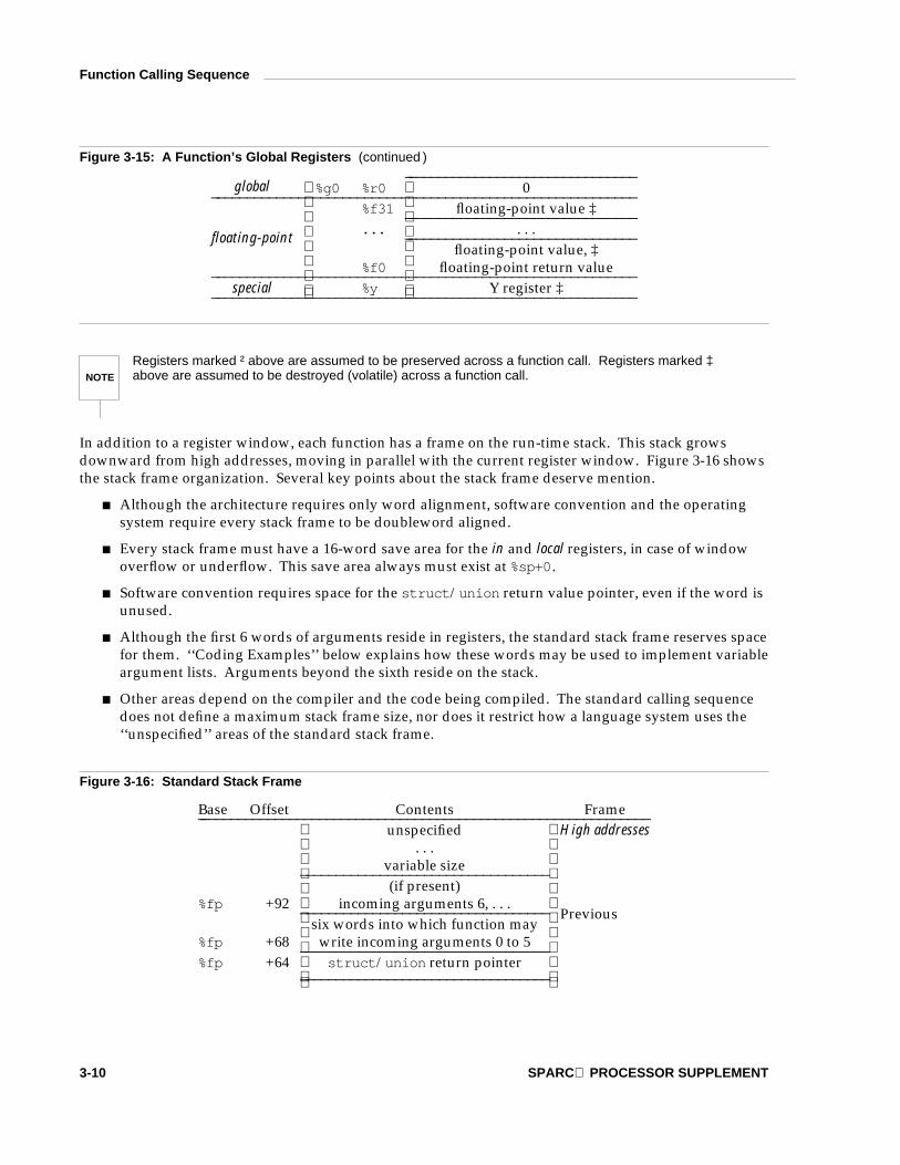
Figure 3-15: A Function’s Global Registers
Type Name Usage_ _________________________________________________________% g 7 % r 7 global 7 (reserved for system)_ _______________________________% g 6 % r 6 global 6 (reserved for system)_ _______________________________% g 5 % r 5 global 5 (reserved for system)_ _______________________________% g 4 % r 4 global 4 (reserved for application)_ _______________________________% g 3 % r 3 global 3 (reserved for application)_ _______________________________% g 2 % r 2 global 2 (reserved for application)_ _______________________________% g 1 % r 1 global 1 ‡
LOW-LEVEL SYSTEM INFORMATION 3-9
Function Calling Sequence
Figure 3-15: A Function’s Global Registers (continued )_ _______________________________
global % g 0 % r 0 0_ _________________________________________________________% f 3 1 floating-point value ‡_ _______________________________. . . . . ._ _______________________________
floating-point value, ‡floating-point
% f 0 floating-point return value_ _________________________________________________________special % y Y register ‡_ _________________________________________________________
NOTE
Registers marked † above are assumed to be preserved across a function call. Registers marked ‡above are assumed to be destroyed (volatile) across a function call.
In addition to a register window, each function has a frame on the run-time stack. This stack growsdownward from high addresses, moving in parallel with the current register window. Figure 3-16 showsthe stack frame organization. Several key points about the stack frame deserve mention.
Although the architecture requires only word alignment, software convention and the operatingsystem require every stack frame to be doubleword aligned.
Every stack frame must have a 16-word save area for the in and local registers, in case of windowoverflow or underflow. This save area always must exist at % s p + 0.
Software convention requires space for the s t r u c t/u n i o n return value pointer, even if the word isunused.
Although the first 6 words of arguments reside in registers, the standard stack frame reserves spacefor them. ‘‘Coding Examples’’ below explains how these words may be used to implement variableargument lists. Arguments beyond the sixth reside on the stack.
Other areas depend on the compiler and the code being compiled. The standard calling sequencedoes not define a maximum stack frame size, nor does it restrict how a language system uses the‘‘unspecified’’ areas of the standard stack frame.
Figure 3-16: Standard Stack Frame
Base Offset Contents Frame_ _____________________________________________________________unspecified High addresses
. . .variable size_ _________________________________(if present)
% f p +92 incoming arguments 6, . . ._ _________________________________six words into which function may
% f p +68 write incoming arguments 0 to 5_ _________________________________% f p +64 s t r u c t/u n i o n return pointer
_ _________________________________
Previous
3-10 SPARC PROCESSOR SUPPLEMENT

Function Calling Sequence
Figure 3-16: Standard Stack Frame (continued )
% f p 0 16-word window save area_ _____________________________________________________________% f p –1 unspecified
. . .variable size_ _________________________________(if needed)
% s p +92 outgoing arguments 6, . . ._ _________________________________six words into which callee may
% s p +68 write outgoing arguments 0 to 5_ _________________________________% s p +64 s t r u c t/u n i o n return pointer
_ _________________________________
Current
% s p 0 16-word window save area Low addresses_ _____________________________________________________________
Across function boundaries, the standard function prologue shifts the register window, making the cal-ling function’s out registers the called function’s in registers. It also allocates stack space, including therequired areas of Figure 16 and any private space it needs. The lowest 16 words in the stack must—at alltimes—be reserved as the register save area. The example below illustrates this and allocates 80 bytes forthe stack frame.
Figure 3-17: Function Prologue
second:save %sp, -80, %sp
For demonstration, assume a function named f i r s t calls s e c o n d. The register windows for the twofunctions appear below.
LOW-LEVEL SYSTEM INFORMATION 3-11

Function Calling Sequence
Figure 3-18: Register Windows
f i r s t ( ){
. . .s e c o n d ( ) ;. . .
}
f i r s t
in
local
out
s e c o n d
in
local
out
shared
global
floating-point
As explained later, the function epilogue executes a r e s t o r e instruction to unwind the stack and restorethe register windows to their original condition.
NOTE
Strictly speaking, a function does not need the s a v e and r e s t o r e instructions if it preserves the regis-ters as described below. Although some functions can be optimized to eliminate the s a v e andr e s t o r e, the general case uses the standard prologue and epilogue.
Some registers have assigned roles.
% s p or % o 6 The stack pointer holds the limit of the current stack frame, which is the address of thestack’s bottommost, valid word. Stack contents below the stack pointer areundefined. At all times the stack pointer must point to a doubleword aligned, 16-word window save area.
% f p or % i 6 The frame pointer holds the address of the previous stack frame, which coincides withthe word immediately above the current frame. Consequently, a function has regis-ters pointing to both ends of its frame. Incoming arguments reside in the previousframe, referenced as positive offsets from % f p.
% i 0 and % o 0 Integral and pointer return values appear in % i 0. A function that returns a structure,union, or quad-precision value places the address of the result in % i 0. A callingfunction receives values in the coincident out register, % o 0.
% i 7 and % o 7 The return address is the location to which a function should return control. Because acalling function’s out registers coincide with the called function’s in registers, the cal-ling function puts a return address in its own % o 7, while the called function finds thereturn address in % i 7.
Actually, the return address register holds the call instruction’s address, normallymaking the return address % i 7 + 8 for the called function. (Every call instruction hasa delay instruction.) Between function calls, % o 7 serves as a scratch register.
3-12 SPARC PROCESSOR SUPPLEMENT

Function Calling Sequence
% f 0 and % f 1 Floating-point return values appear in the floating-point registers. Single-precisionvalues occupy % f 0; double-precision values occupy % f 0 and % f 1. Otherwise, theseare scratch registers.
% i 0 through % i 5 Incoming parameters use up to 6 in registers. Arguments beyond the sixth wordappear on the stack, as explained above. See the discussion below on structures,unions, and floating-point values.
% o 0 through % o 5 Outgoing arguments use up to 6 out registers. Argument words beyond the sixth arewritten onto the stack.
% l 0 through % l 7 Local registers have no specified role in the standard calling sequence.
% f 0 through % f 3 1 Except for floating-point return values, global floating-point registers have no specifiedrole in the standard calling sequence.
% g 0 and % g 1 Global integer registers 0 and 1 have no specified role in the standard calling sequence.
% g 2 through % g 4 Global integer registers 2, 3, and 4 are reserved for the application software. Systemsoftware (including the libraries described in Chapter 6) preserves these registers’values for the application. Their use is intended to be controlled by the compilationsystem and must be consistent throughout the application.
% g 5 through % g 7 Global integer registers 5, 6, and 7 are reserved for system software. Because systemsoftware provides the low-level operating system interface, including signal han-dling, an application cannot change the registers and safely preserve the systemvalues, even by saving and restoring them across function calls. Therefore, applica-tion software must not change these registers’ values.
% y The Y register has no specified role in the standard calling sequence.
With some exceptions given below, all registers visible to both a calling and a called function ‘‘belong’’ tothe called function. In other words, a called function may use all visible registers without saving theirvalues before it changes them, and without restoring their values before it returns. Registers in thiscategory include global, floating-point, out (for the calling function), in (for the called function), the Y regis-ter, the processor state register (PSR), and the floating-point state register (FSR). Correspondingly, if acalling function wants to preserve such a register value across a function call, it must save the value andrestore it explicitly. Local registers in each window are private. A called function should not change itscalling function’s local or in registers, even though the registers may be visible temporarily. The excep-tions are the stack pointer, % s p, and global registers % g 5 through % g 7. A called function is obligated topreserve the stack pointer for its caller; application programs must never change the system global regis-ters.
Signals can interrupt processes [see s i g n a l(BA_OS)]. Functions called during signal handling have nounusual restrictions on their use of registers. Moreover, if a signal handling function returns, the processresumes its original execution path with registers restored to their original values. Thus programs andcompilers may freely use all registers, even global and floating-point registers, without the danger of signalhandlers changing their values.
LOW-LEVEL SYSTEM INFORMATION 3-13

Function Calling Sequence
Integral and Pointer Arguments
As mentioned, a function receives its first 6 argument words through the in registers: % i 0 is the first, % i 1is the second, and so on. Functions pass all integer-valued arguments as words, expanding signed orunsigned bytes and halfwords as needed. If a function call has more than 6 integral or pointer argu-ments, the others go on the stack.
Figure 3-19: Integral and Pointer Arguments
Call Argument Caller Callee_ ______________________________________________1 % o 0 % i 02 % o 1 % i 13 % o 2 % i 24 % o 3 % i 35 % o 4 % i 46 % o 5 % i 57 % s p + 9 2 % f p + 9 2
g ( 1 , 2 , 3 , 4 ,5 , 6 , 7 ,( v o i d * ) 0 ) ;
( v o i d * ) 0 % s p + 9 6 % f p + 9 6_ ______________________________________________
Floating-Point Arguments
The integer in registers also hold floating-point arguments: single-precision values use one register anddouble-precision use two. See the following section for information on quad-precision values. Asfloating-point operations cannot use the integer registers, compilers normally store the input registers tothe stack before operating on floating-point values. See ‘‘Coding Examples’’ for information aboutfloating-point arguments and variable argument lists. The example below uses only double-precisionarguments. Single-precision arguments behave similarly.
Figure 3-20: Floating-Point Arguments
Call Argument Caller Callee___________________________________________________word 0, 1 . 4 1 4 % o 0 % i 0word 1, 1 . 4 1 4 % o 1 % i 11 % o 2 % i 2word 0, 2 . 9 9 8 e 1 0 % o 3 % i 3word 1, 2 . 9 9 8 e 1 0 % o 4 % i 4word 0, 2 . 7 1 8 % o 5 % i 5
h ( 1 . 4 1 4 , 1 ,2 . 9 9 8 e 1 0 ,2 . 7 1 8 ) ;
word 1, 2 . 7 1 8 % s p + 9 2 % f p + 9 2___________________________________________________
3-14 SPARC PROCESSOR SUPPLEMENT

Function Calling Sequence
Structure, Union, and Quad-Precision Arguments
As described in the data representation section, structures and unions can have byte, halfword, word, ordoubleword alignment, depending on the constituents. To ensure proper argument alignment and tofacilitate addressing, structure and union objects are not passed directly in the argument list. Quad-precision values follow the same conventions as structures and unions.
The example below shows the effect only; C code does not change.
Figure 3-21: Sending Structure, Union, and Quad-Precision Arguments
Source Compiler’s Internal Form_ __________________________ _ __________________________c a l l e r ( ) c a l l e r ( ){ {
s t r u c t s s ; s t r u c t s s , s 2 ;
c a l l e e ( s ) ; s 2 = s ;} c a l l e e ( & s 2 ) ;
}_ __________________________ _ __________________________
Addresses occupy one word; so structure, unions, and quad-precision values occupy a single word asfunction arguments. In this respect, these arguments behave the same as integral and pointer arguments,described above. The example’s temporary copy of the object, s 2 above, provides call-by-value seman-tics, letting the called function modify its arguments without affecting the calling function’s object, sabove.
Because the calling function passes a pointer in the argument list, the compiled code for the called func-tion must accept the same. Underlying machinations are transparent to the source program. The com-piler translates appropriately, implicitly dereferencing the pointer as needed. Code for a called functionmight appear as follows. Again, the example below shows the effect only; C code does not change.
Figure 3-22: Receiving Structure, Union, and Quad-Precision Arguments
Source Compiler’s Internal Form_ __________________________ _ __________________________c a l l e e ( s t r u c t s a r g ) c a l l e e ( s t r u c t s * a r g ){ {
s t r u c t s s , s 2 ; s t r u c t s s , s 2 ;
s . m = a r g . m ; s . m = a r g - > m ;s 2 = a r g ; s 2 = * a r g ;
} }_ __________________________ _ __________________________
LOW-LEVEL SYSTEM INFORMATION 3-15

Function Calling Sequence
Functions Returning Scalars or No Value
A function that returns an integral or pointer value places its result in % i 0; the calling function finds thatvalue in % o 0.
A floating-point return value appears in the floating-point registers for both the calling and the calledfunction. Single-precision uses % f 0; double-precision uses % f 0 and % f 1; quad-precision uses the samemethod as structures and unions, described below.
Functions that return no value (also called procedures or v o i d functions) put no particular value in anyreturn register. Those registers may be used as scratch registers, however.
A call instruction writes its own address into out register % o 7. As usual for a control transfer instruction,the call instruction takes a delay instruction that is executed before the first instruction of the called func-tion. Because every instruction is one word long, the return address is the address of the call instructionplus 8. This value is % i 7 + 8 for the called function and % o 7 + 8 for the calling function. The followingexample returns the value contained in local register % l 4.
Figure 3-23: Function Epilogue
jmpl %i7 + 8, %g0restore %l4, 0, %o0
If a function returns no value, or if the return register already contains the desired value, the next epilo-gue would suffice.
Figure 3-24: Alternative Function Epilogue
jmpl %i7 + 8, %g0restore %g0, 0, %g0
Functions Returning Structures, Unions, or Quad-Precision Values
As shown above, every stack frame reserves the word at % f p + 6 4. If a function returns a structure, union,or quad-precision value, this word should hold the address of the object into which the return valueshould be copied. The caller provides space for the return value and places its address in the stack frame(the word is at % s p + 6 4 for the caller). Having the caller supply the return object’s space allows re-entrancy.
3-16 SPARC PROCESSOR SUPPLEMENT

Function Calling Sequence
NOTE
Structures and unions in this context have fixed sizes. The ABI does not specify how to handle variablesized objects.
A function returning a structure, union, or quad-precision value also sets % i 0 to the value it finds in% f p + 6 4. Thus when the caller receives control again, the address of the returned object resides in register% o 0.
Both the calling and the called functions must cooperate to pass the return value successfully:
The calling function must supply space for the return value and pass its address in the stack frame;
The called function must use the address from the frame and copy the return value to the object sosupplied.
Failure of either side to meet its obligations leads to undefined program behavior. The standard functioncalling sequence includes a method to detect such failures and to detect type mismatches.
Whenever a calling function expects a structure, union, or quad-precision return value from the functionbeing called, the compiler generates an u n i m p (unimplemented) instruction immediately following thedelay instruction of the call. The u n i m p instruction’s immediate field holds the low-order 12 bits of theexpected return value’s size (higher bits are masked if the object is larger than 4095 bytes). When prepar-ing to return its value, the called function checks for the presence of the u n i m p instruction, and it checksthat the low-order 12 bits agree with the low-order 12 bits of the size it plans to copy. If all tests pass, thefunction copies the value and returns to % i 7 + 1 2, skipping the call instruction, the delay instruction, andthe u n i m p instruction.
If the called function disagrees with the caller’s object size, it returns to % i 7 + 8, executes the u n i m pinstruction and causes an illegal instruction trap. If the called function does not return a structure, union,or quad-precision value, it will return to % i 7 + 8, trapping similarly. See section ‘‘Trap Interface’’ in thischapter for more information about traps.
Finally, if the called function returns a structure, union, or quad-precision value but the calling functiondoesn’t expect one, the called function copies nothing, returns to % i 7 + 8, and continues executing (therewill be no u n i m p instruction). Of course, the caller should assume no return value is present; both % i 0and % f 0 have unpredictable values in this case. The following example assumes the return object hasalready been copied and its address is in local register % l 4.
Figure 3-25: Function Epilogue
jmpl %i7 + 12, %g0restore %l4, 0, %o0
LOW-LEVEL SYSTEM INFORMATION 3-17

Operating System Interface
Virtual Address Space
Processes execute in a 32-bit virtual address space. Memory management hardware translates virtualaddresses to physical addresses, hiding physical addressing and letting a process run anywhere in thesystem’s real memory. Processes typically begin with three logical segments, commonly called text, data,and stack. As Chapter 5 describes, dynamic linking creates more segments during execution, and a pro-cess can create additional segments for itself with system services.
Page Size
Memory is organized by pages, which are the system’s smallest units of memory allocation. Page sizecan vary from one system to another, depending on the processor, memory management unit and systemconfiguration. Processes may call s y s c o n f(BA_OS) to determine the system’s current page size. Themaximum page size for SPARC is 64 KB.
Virtual Address Assignments
Conceptually, processes have the full 32-bit address space available. In practice, however, several factorslimit the size of a process.
The system reserves a configuration-dependent amount of virtual space.
A tunable configuration parameter limits process size.
A process whose size exceeds the system’s available, combined physical memory and secondarystorage cannot run. Although some physical memory must be present to run any process, the sys-tem can execute processes that are bigger than physical memory, paging them to and from secon-dary storage. Nonetheless, both physical memory and secondary storage are shared resources.System load, which can vary from one program execution to the next, affects the available amounts.
Figure 3-26: Virtual Address Configuration____________________
0 x f f f f f f f f Reserved End of memory. . .
____________________Stack and
dynamic segments. . .
________________________________________
. . .0 Loadable segments Beginning of memory____________________
Loadable segmentsProcesses’ loadable segments may begin at 0. The exact addresses depend on the execut-able file format [see Chapters 4 and 5].
Stack and dynamic segmentsA process’s stack and dynamic segments reside below the reserved area. Processes cancontrol the amount of virtual memory allotted for stack space, as described below.
3-18 SPARC PROCESSOR SUPPLEMENT

Operating System Interface
Reserved A reserved area resides at the top of virtual space.
NOTE
Although application programs may begin at virtual address 0, they conventionally begin above0 x 1 0 0 0 0 (64 K), leaving the initial 64 K with an invalid address mapping. Processes that reference thisinvalid memory (for example, by dereferencing a null pointer) generate an access exception trap, asdescribed in the ‘‘Trap Interface’’ section of this chapter. A process may, however, establish a validmapping for this area using the m m a p(KE_OS) facilities.
As the figure shows, the system reserves the high end of virtual space, with a process’s stack anddynamic segments below that. Although the exact boundary between the reserved area and a processdepends on the system’s configuration, the reserved area shall not consume more than 512 MB from thevirtual address space. Thus the user virtual address range has a minimum upper bound of 0 x d f f f f f f f.Individual systems may reserve less space, increasing processes’ virtual memory range. More informa-tion follows in the section ‘‘Managing the Process Stack.’’
Although applications may control their memory assignments, the typical arrangement follows thediagram above. Loadable segments reside at low addresses; dynamic segments occupy the higher range.When applications let the system choose addresses for dynamic segments (including shared object seg-ments), it chooses high addresses. This leaves the ‘‘middle’’ of the address spectrum available fordynamic memory allocation with facilities such as m a l l o c(BA_OS).
Managing the Process Stack
Section ‘‘Process Initialization’’ in this chapter describes the initial stack contents. Stack addresses canchange from one system to the next—even from one process execution to the next on the same system.Processes, therefore, should not depend on finding their stack at a particular virtual address.
A tunable configuration parameter controls the system maximum stack size. A process also can uses e t r l i m i t(BA_OS), to set its own maximum stack size, up to the system limit. On SPARC, the stack seg-ment has read, write, and execute permissions.
Coding Guidelines
Operating system facilities, such as m m a p(KE_OS), allow a process to establish address mappings in twoways. First, the program can let the system choose an address. Second, the program can force the systemto use an address the program supplies. This second alternative can cause application portability prob-lems, because the requested address might not always be available. Differences in virtual address spacecan be particularly troublesome between different architectures, but the same problems can arise within asingle architecture.
Processes’ address spaces typically have three segment areas that can change size from one execution tothe next: the stack [through s e t r l i m i t(BA_OS)], the data segment [through m a l l o c(BA_OS)], and thedynamic segment area [through m m a p(KE_OS)]. Changes in one area may affect the virtual addressesavailable for another. Consequently, an address that is available in one process execution might not beavailable in the next. A program that used m m a p(KE_OS) to request a mapping at a specific address thuscould appear to work in some environments and fail in others. For this reason, programs that wish toestablish a mapping in their address space should let the system choose the address.
Despite these warnings about requesting specific addresses, the facility can be used properly. For exam-ple, a multiprocess application might map several files into the address space of each process and buildrelative pointers among the files’ data. This could be done by having each process ask for a certainamount of memory at an address chosen by the system. After each process receives its own, privateaddress from the system, it would map the desired files into memory, at specific addresses within the ori-ginal area. This collection of mappings could be at different addresses in each process but their relative
LOW-LEVEL SYSTEM INFORMATION 3-19

Operating System Interface
positions would be fixed. Without the ability to ask for specific addresses, the application could not buildshared data structures, because the relative positions for files in each process would be unpredictable.
Trap Interface
Two execution modes exist in the SPARC architecture: user and supervisor. Processes run in user mode,and the operating system kernel runs in supervisor mode. As the SPARC architecture manual describes,the processor changes mode to handle traps, which may be precise, interrupting or deferred. Precise anddeferred traps, being caused by instruction execution, can be explicitly generated by a process. This sec-tion, therefore, specifies those trap types with defined behavior.
Hardware Trap Types
The operating system defines the following correspondence between hardware traps and the signalsspecified by s i g n a l(BA_OS).
Figure 3-27: Hardware Traps and Signals
Trap Name Signal_ ___________________________________________cp_disabled S I G I L Lcp_exception S I G I L Ldata_access_error unspecifieddata_access_exception S I G S E G V, S I G B U Sdata_store_error unspecifieddivision_by_zero S I G F P Efp_disabled S I G I L Lfp_exception S I G F P Eillegal_instruction S I G I L Linstruction_access_exception S I G S E G V, S I G B U Smem_address_not_aligned S I G B U Sprivileged_instruction S I G I L Lr_register_access_error unspecifiedtag_overflow S I G E M Ttrap_instruction see next tablewindow_overflow nonewindow_underflow none_ ___________________________________________
Two trap types, instruction_access_exception and data_access_exception, can generate two signals. Inboth cases, the ‘‘normal’’ signal is S I G S E G V. Nonetheless, if the access also causes some external memoryerror (such as a parity error), the system generates S I G B U S.
Floating-point instructions exist in the architecture, but they may be implemented either in hardware orsoftware. If the fp_disabled or fp_exception trap occurs because of an unimplemented, valid instruction,the process receives no signal. Instead, the system intercepts the trap, emulates the instruction, andreturns control to the process. A process receives S I G I L L for the fp_disabled trap only when the indi-cated floating-point instruction is illegal (invalid encoding, and so on).
3-20 SPARC PROCESSOR SUPPLEMENT

Operating System Interface
Software Trap Types
The operating system defines the following correspondence between software traps and the signalsspecified by s i g n a l(BA_OS).
Figure 3-28: Software Trap Types
Trap Number Signal Purpose_ __________________________________________________________0 S I G S Y S System calls1 S I G T R A P Breakpoints2 S I G F P E Division by zero3 none Flush windows4 none Clean windows5 S I G I L L Range checking6 none Fix alignment7 S I G F P E Integer overflow8 S I G S Y S System calls
9-15 unspecified Reserved for the operating system16-31 S I G I L L Unspecified
32 none Get integer condition codes33 none Set integer condition codes
34-127 unspecified Reserved for the operating system_ __________________________________________________________
0 and 8 System calls, or requests for operating system services, use a type 0 or 8 trap instruction forthe low-level implementation. Normally, system calls do not generate a signal, but S I G S Y Scan occur in some error conditions. Both trap numbers are reserved, and they are not (neces-sarily) equivalent.
NOTE
The ABI does not define the implementation of individual system calls. Instead, programs should usethe system libraries that Chapter 6 describes. Programs with embedded system call trap instructions donot conform to the ABI.
1 A debugger can set a breakpoint by inserting a trap instruction whose type is 1.
2 A process can explicitly signal division by zero with this trap.
3 By executing a type 3 trap, a process asks the system to flush all its register windows to thestack.
4 Normally during process execution, s a v e instructions allocate new register windows withundefined local and out register contents. Executing a type 4 trap causes the system to initial-ize local and out registers in all subsequent new windows either to zero or to a valid programcounter value. In addition, new windows allocated when a s a v e instruction generates awindow_overflow trap are also initialized in this manner. This behavior continues until theprocess terminates.
5 A process can explicitly signal a range checking error with this trap.
LOW-LEVEL SYSTEM INFORMATION 3-21

Operating System Interface
6 Executing a type 6 trap makes the operating system ‘‘fix’’ subsequent unaligned data refer-ences. Although the references still generate memory_address_not_aligned traps, the operat-ing system handles the trap, emulates the data references, and returns control to the processwithout generating a signal. In this context, a ‘‘data reference’’ is a load or a store operation.Implicit memory references, such as control transfers, must always be aligned properly, andthe stack must always be aligned as described elsewhere.
7 A process can explicitly signal integer overflow with this trap. Either a positive or a negativevalue can cause overflow.
9 to 15 The operating system reserves these trap types for its own use. Programs that use them donot conform to the ABI.
16 to 31 Software trap types in this range have no specified meaning; moreover, they will never bespecified. Thus these trap types are reserved for process-specific, machine-specific, andsystem-specific purposes. Besides receiving signal S I G I L L for these traps, the signal handlerreceives the trap type (16-31) as the signal code.
32 Executing a type 32 trap instruction copies the integer condition codes from the PSR to globalregister % g 1. The result is right-justified; other % g 1 bits are set to zero.
33 Executing a type 33 trap instruction copies the rightmost four bits from global register % g 1 tothe PSR integer condition codes. Other bits in % g 1 are ignored.
34 to 127 The operating system reserves these trap types for its own use. Programs that use them donot conform to the ABI.
Process Initialization
This section describes the machine state that e x e c(BA_OS) creates for ‘‘infant’’ processes, including argu-ment passing, register usage, stack frame layout, and so on. Programming language systems use this ini-tial program state to establish a standard environment for their application programs. As an example, aC program begins executing at a function named m a i n, conventionally declared in the following way.
Figure 3-29: Declaration for m a i n
e x t e r n i n t m a i n ( i n t a r g c , c h a r * a r g v [ ] , c h a r * e n v p [ ] ) ;
Briefly, a r g c is a non-negative argument count; a r g v is an array of argument strings, witha r g v [ a r g c ] = = 0; and e n v p is an array of environment strings, also terminated by a null pointer.
Although this section does not describe C program initialization, it gives the information necessary toimplement the call to m a i n or to the entry point for a program in any other language.
3-22 SPARC PROCESSOR SUPPLEMENT

Operating System Interface
Special Registers
As the architecture defines, two state registers control and monitor the processor: the processor stateregister (PSR) and the floating-point state register (FSR). Application programs cannot access the PSRdirectly; they run in the processor’s user mode , and the instructions to read and write the PSR areprivileged. Nonetheless, a program ‘‘sees’’ a processor that behaves as if the PSR had the followingvalues. PSR fields not in the table either have unspecified values or do not affect user program behavior.
Figure 3-30: Processor State Register Fields
Field Value Note_ ____________________________________________________icc unspecified Integer condition codes unspecifiedEC unspecified Coprocessor not specifiedS 0 Processes run in user modeET 1 Traps enabled_ ____________________________________________________
No standard coprocessor is specified by the ABI. Applications that directly execute coprocessor operateinstructions do not conform to the ABI. Individual system implementations may use a coprocessor (toimprove performance, for example), but such use of the coprocessor should be under the control of systemsoftware, not the application.
Similarly, ancillary state registers (ASR’s) besides the Y register either are privileged or unspecified by thearchitecture. Applications thus may not execute the r d a s r and w r a s r instructions, with the exceptionsof r d y and w r y.
The architecture defines floating-point instructions, and those instructions work whether the processorhas a hardware floating-point unit or not. (A system may provide hardware or software floating-pointfacilities.) Consequently, the EF bit in the PSR is unspecified, letting the system set it according to thehardware configuration. In either case, however, the processor presents a working floating-point imple-mentation, including an FSR with the following initial values.
Figure 3-31: Floating-Point State Register Fields
Field Value Note_ __________________________________________________________RD 0 Round to nearestTEM 0 Floating-point traps not enabledNS 0 Nonstandard mode offftt unspecified Floating-point trap type unspecifiedqne 0 Floating-point queue is emptyfcc unspecified Floating-point condition codes unspecifiedaexc 0 No accrued exceptionscexc 0 No current exceptions_ __________________________________________________________
LOW-LEVEL SYSTEM INFORMATION 3-23

Operating System Interface
Process Stack and Registers
When a process receives control, its stack holds the arguments and environment from e x e c(BA_OS).
Figure 3-32: Initial Process Stack_ ____________________________
Unspecified High addresses_ ____________________________Information block, including
argument stringsenvironment strings
auxiliary information. . .
(size varies)_ ____________________________Unspecified_ ____________________________
Null auxiliary vector entry_ ____________________________Auxiliary vector
. . .(2-word entries)_ ____________________________
0 word_ ____________________________Environment pointers
. . .(one word each)_ ____________________________
0 word_ ____________________________Argument pointers
. . .(Argument count words)_ ____________________________
% s p + 6 4 Argument count_ ____________________________Window save area
% s p + 0 (16 words) Low addresses_ ____________________________
Argument strings, environment strings, and the auxiliary information appear in no specific order withinthe information block; the system makes no guarantees about their arrangement. The system also mayleave an unspecified amount of memory between the null auxiliary vector entry and the beginning of theinformation block.
Except as shown below, global, floating-point, and window registers have unspecified values at processentry. Consequently, a program that requires registers to have specific values must set them explicitlyduring process initialization. It should not rely on the system to set all registers to zero.
% g 1 A non-zero value gives a function pointer that the application should registerwith a t e x i t(BA_OS). If %g1 contains zero, no action is required.
% g 2, % g 3, and % g 4 These registers are currently set to zero. Future versions of the system might usethe registers to hold special values; so applications should not depend on theseregisters’ values.
% f p The system marks the deepest stack frame by setting the frame pointer to zero.No other frame’s % f p has a zero value.
3-24 SPARC PROCESSOR SUPPLEMENT

Operating System Interface
% s p Performing its usual job, the stack pointer holds the address of the bottom of thestack, which is guaranteed to be doubleword aligned.
Every process has a stack, but the system defines no fixed stack address. Furthermore, a program’s stackaddress can change from one system to another—even from one process invocation to another. Thus theprocess initialization code must use the stack address in % s p. Data in the stack segment at addressesbelow the stack pointer contain undefined values.
Whereas the argument and environment vectors transmit information from one application program toanother, the auxiliary vector conveys information from the operating system to the program. This vectoris an array of the following structures, interpreted according to the a _ t y p e member.
Figure 3-33: Auxiliary Vector
typedef struct{
int a_type;union {
long a_val;void *a_ptr;void (*a_fcn)();
} a_un;} auxv_t;
Figure 3-34: Auxiliary Vector Types, a _ t y p e
Name Value a _ u n_ ____________________________A T _ N U L L 0 ignoredA T _ I G N O R E 1 ignoredA T _ E X E C F D 2 a _ v a lA T _ P H D R 3 a _ p t rA T _ P H E N T 4 a _ v a lA T _ P H N U M 5 a _ v a lA T _ P A G E S Z 6 a _ v a lA T _ B A S E 7 a _ p t rA T _ F L A G S 8 a _ v a lA T _ E N T R Y 9 a _ p t r_ ____________________________
A T _ N U L L The auxiliary vector has no fixed length; instead its last entry’s a _ t y p e member has thisvalue.
LOW-LEVEL SYSTEM INFORMATION 3-25

Operating System Interface
A T _ I G N O R E This type indicates the entry has no meaning. The corresponding value of a _ u n isundefined.
A T _ E X E C F D As Chapter 5 describes, e x e c(BA_OS) may pass control to an interpreter program. Whenthis happens, the system places either an entry of type A T _ E X E C F D or one of typeA T _ P H D R in the auxiliary vector. The entry for type A T _ E X E C F D uses the a _ v a l memberto contain a file descriptor open to read the application program’s object file.
A T _ P H D R Under some conditions, the system creates the memory image of the application programbefore passing control to the interpreter program. When this happens, the a _ p t rmember of the A T _ P H D R entry tells the interpreter where to find the program headertable in the memory image. If the A T _ P H D R entry is present, entries of types A T _ P H E N T,A T _ P H N U M, and A T _ E N T R Y must also be present. See Chapter 5 in both the System V ABIand the processor supplement for more information about the program header table.
A T _ P H E N T The a _ v a l member of this entry holds the size, in bytes, of one entry in the programheader table to which the A T _ P H D R entry points.
A T _ P H N U M The a _ v a l member of this entry holds the number of entries in the program header tableto which the A T _ P H D R entry points.
A T _ P A G E S Z If present, this entry’s a _ v a l member gives the system page size, in bytes. The sameinformation also is available through s y s c o n f(BA_OS).
A T _ B A S E The a _ p t r member of this entry holds the base address at which the interpreter programwas loaded into memory. See ‘‘Program Header’’ in the System V ABI for more informa-tion about the base address.
A T _ F L A G S If present, the a _ v a l member of this entry holds one-bit flags. Bits with undefinedsemantics are set to zero.
A T _ E N T R Y The a _ p t r member of this entry holds the entry point of the application program towhich the interpreter program should transfer control.
Other auxiliary vector types are reserved. Currently, no flag definitions exist for A T _ F L A G S. Nonetheless,bits under the 0 x f f 0 0 0 0 0 0 mask are reserved for system semantics.
In the following example, the stack resides below 0 x f 8 0 0 0 0 0 0, growing toward lower addresses. Theprocess receives three arguments.
c p
s r c
d s t
It also inherits two environment strings (this example is not intended to show a fully configured execu-tion environment).
H O M E = / h o m e / d i r
P A T H = / h o m e / d i r / b i n : / u s r / b i n :
Its auxiliary vector holds one non-null entry, a file descriptor for the executable file.
1 3
The initialization sequence preserves the stack pointer’s doubleword alignment.
3-26 SPARC PROCESSOR SUPPLEMENT

Operating System Interface
Figure 3-35: Example Process Stack_ ____________________n : \ 0 pad_ ____________________r / b i_ ____________________: / u s_ ____________________
0 x f 7 f f f f f 0 / b i n_ ____________________/ d i r_ ____________________h o m e_ ____________________T H = /_ ____________________
0 x f 7 f f f f e 0 r \ 0 P A_ ____________________e / d i_ ____________________/ h o m_ ____________________O M E =_ ____________________
0 x f 7 f f f f d 0 s t \ 0 H_ ____________________r c \ 0 d_ ____________________c
p
\ 0
s_ ____________________0_ ____________________
0 x f 7 f f f f c 0 0_ ____________________1 3_ ____________________2_ ____________________0_ ____________________
0 x f 7 f f f f b 0 0 x f 7 f f f f e 2_ ____________________0 x f 7 f f f f d 3_ ____________________
0_ ____________________0 x f 7 f f f f c f_ ____________________
0 x f 7 f f f f a 0 0 x f 7 f f f f c b_ ____________________0 x f 7 f f f f c 8_ ____________________
0 x f 7 f f f f 9 8 3_ ____________________Window save area
% s p + 0 , 0 x f 7 f f f f 5 8 (16 words)_ ____________________
LOW-LEVEL SYSTEM INFORMATION 3-27

Coding Examples
This section discusses example code sequences for fundamental operations such as calling functions,accessing static objects, and transferring control from one part of a program to another. Previous sectionsdiscuss how a program may use the machine or the operating system, and they specify what a programmay and may not assume about the execution environment. Unlike previous material, the informationhere illustrates how operations may be done, not how they must be done.
As before, examples use the ANSI C language. Other programming languages may use the same conven-tions displayed below, but failure to do so does not prevent a program from conforming to the ABI. Twomain object code models are available.
Absolute code . Instructions can hold absolute addresses under this model. To execute properly, theprogram must be loaded at a specific virtual address, making the program’s absolute addressescoincide with the process’s virtual addresses.
Position-independent code . Instructions under this model hold relative addresses, not absoluteaddresses. Consequently, the code is not tied to a specific load address, allowing it to executeproperly at various positions in virtual memory.
Size and performance considerations further require large and small position-independent models, giv-ing three models total. Following sections describe the differences between these models. Codesequences for the three models (when different) appear together, allowing easier comparison.
NOTE
Examples below show code fragments with various simplifications. They are intended to explainaddressing modes, not to show optimal code sequences nor to reproduce compiler output.
NOTE
When other sections of this document show assembly language code sequences, they typically showonly the absolute versions. Information in this section explains how position-independent code wouldalter the examples.
Code Model Overview
When the system creates a process image, the executable file portion of the process has fixed addresses,and the system chooses shared object library virtual addresses to avoid conflicts with other segments inthe process. To maximize text sharing, shared objects conventionally use position-independent code, inwhich instructions contain no absolute addresses. Shared object text segments can be loaded at variousvirtual addresses without having to change the segment images. Thus multiple processes can share a sin-gle shared object text segment, even though the segment resides at a different virtual address in each pro-cess.
Position-independent code relies on two techniques.
Control transfer instructions hold addresses relative to the program counter (PC). A PC-relativebranch or function call computes its destination address in terms of the current program counter,not relative to any absolute address.
When the program requires an absolute address, it computes the desired value. Instead of embed-ding absolute addresses in the instructions, the compiler generates code to calculate an absoluteaddress during execution.
Because the processor architecture provides PC-relative call and branch instructions, compilers can satisfy
3-28 SPARC PROCESSOR SUPPLEMENT

Coding Examples
the first condition easily.
A global offset table provides information for address calculation. Position-independent object files (exe-cutable and shared object files) have a table in their data segment that holds addresses. When the systemcreates the memory image for an object file, the table entries are relocated to reflect the absolute virtualaddresses as assigned for an individual process. Because data segments are private for each process, thetable entries can change—unlike text segments, which multiple processes share.
Two position-independent models give programs a choice between more efficient code with some sizerestrictions and less efficient code without those restrictions. Because of the processor’s architecture, aglobal offset table with no more than 2048 entries (8192 bytes) is more efficient than a larger one. Pro-grams that need more entries must use the larger, more general code.
Position-Independent Function Prologue
This section describes the function prologue for position-independent code. A function’s prologue firstallocates the local stack space. Position-independent functions also set local register % l 7 to the globaloffset table’s address, accessed with the symbol _ G L O B A L _ O F F S E T _ T A B L E _. Because % l 7 is private foreach function and preserved across function calls, a function calculates its value once at the entry.
NOTE
As a reminder, this entire section contains examples. Using % l 7 is a convention, not a requirement;moreover, this convention is private to a function. Not only could other registers serve the same pur-pose, but different functions in a program could use different registers.
To explain the following, code before label 1 : updates the stack pointer as usual. The c a l l instructionputs its own absolute address into register % o 7. The next two instructions calculate the offset between thec a l l instruction and the global offset table. Adding the c a l l instruction’s address to the computedoffset gives the global offset table’s absolute address.
NOTE
When an instruction uses _ G L O B A L _ O F F S E T _ T A B L E _, it sees the offset between the current instructionand the global offset table as the symbol value.
Figure 3-36: Position-Independent Function Prologue_______________________________________________________________n a m e :
s a v e % s p , - 8 0 , % s p1 : c a l l 2 f
s e t h i % h i ( _ G L O B A L _ O F F S E T _ T A B L E _ + ( . - 1 b ) ) , % l 72 : o r % l 7 , % l o ( _ G L O B A L _ O F F S E T _ T A B L E _ + ( . - 1 b ) ) , % l 7
a d d % l 7 , % o 7 , % l 7_______________________________________________________________
Both large and small position-independent models use this prologue. All models use the same functionepilogue.
LOW-LEVEL SYSTEM INFORMATION 3-29

Coding Examples
Data Objects
This discussion excludes stack-resident objects, because programs always compute their virtual addressesrelative to the stack and frame pointers. Instead, this section describes objects with static storage dura-tion.
In the SPARC architecture, only load and store instructions access memory. Because instructions cannothold 32-bit addresses directly, a program normally computes an address into a register. Symbolic refer-ences in absolute code put the symbols’ values—or absolute virtual addresses—into instructions.
Figure 3-37: Absolute Load and Store
C Assembly_ ____________________ _ ________________________________________e x t e r n i n t s r c ; . g l o b a l s r c , d s t , p t re x t e r n i n t d s t ;e x t e r n i n t * p t r ;p t r = & d s t ; s e t h i % h i ( d s t ) , % o 0
o r % l o ( d s t ) , % o 0s e t h i % h i ( p t r ) , % o 1s t % o 0 , [ % o 1 + % l o ( p t r ) ]
* p t r = s r c ; s e t h i % h i ( s r c ) , % o 0l d [ % o 0 + % l o ( s r c ) ] , % o 0s e t h i % h i ( p t r ) , % o 1l d [ % o 1 + % l o ( p t r ) ] , % o 1s t % o 0 , [ % o 1 ]_ ____________________ _ ________________________________________
Position-independent instructions cannot contain absolute addresses. Instead, instructions that referencesymbols hold the symbols’ offsets into the global offset table. Combining the offset with the global offsettable address in % l 7 gives the absolute address of the table entry holding the desired address. A pro-gram whose global offset table has no more than 8192 bytes can use the small model, with a base addressin % l 7 plus a 13-bit, signed offset.
NOTE
When assembling position-independent code, a symbol’s ‘‘value’’ is the offset into the global offsettable, not its virtual address.
Figure 3-38: Small Model Position-Independent Load and Store
C Assembly_ ____________________ _ _______________________________e x t e r n i n t s r c ; . g l o b a l s r c , d s t , p t re x t e r n i n t d s t ;e x t e r n i n t * p t r ;p t r = & d s t ; l d [ % l 7 + d s t ] , % o 0
l d [ % l 7 + p t r ] , % o 1s t % o 0 , [ % o 1 ]
3-30 SPARC PROCESSOR SUPPLEMENT
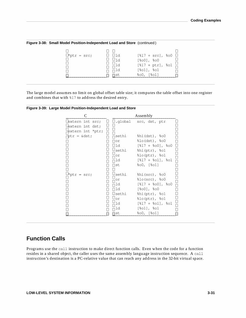
Coding Examples
Figure 3-38: Small Model Position-Independent Load and Store (continued )
* p t r = s r c ; l d [ % l 7 + s r c ] , % o 0l d [ % o 0 ] , % o 0l d [ % l 7 + p t r ] , % o 1l d [ % o 1 ] , % o 1s t % o 0 , [ % o 1 ]_ ____________________ _ _______________________________
The large model assumes no limit on global offset table size; it computes the table offset into one registerand combines that with % l 7 to address the desired entry.
Figure 3-39: Large Model Position-Independent Load and Store
C Assembly_ ____________________ _ _______________________________e x t e r n i n t s r c ; . g l o b a l s r c , d s t , p t re x t e r n i n t d s t ;e x t e r n i n t * p t r ;p t r = & d s t ; s e t h i % h i ( d s t ) , % o 0
o r % l o ( d s t ) , % o 0l d [ % l 7 + % o 0 ] , % o 0s e t h i % h i ( p t r ) , % o 1o r % l o ( p t r ) , % o 1l d [ % l 7 + % o 1 ] , % o 1s t % o 0 , [ % o 1 ]
* p t r = s r c ; s e t h i % h i ( s r c ) , % o 0o r % l o ( s r c ) , % o 0l d [ % l 7 + % o 0 ] , % o 0l d [ % o 0 ] , % o 0s e t h i % h i ( p t r ) , % o 1o r % l o ( p t r ) , % o 1l d [ % l 7 + % o 1 ] , % o 1l d [ % o 1 ] , % o 1s t % o 0 , [ % o 1 ]_ ____________________ _ _______________________________
Function Calls
Programs use the c a l l instruction to make direct function calls. Even when the code for a functionresides in a shared object, the caller uses the same assembly language instruction sequence. A c a l linstruction’s destination is a PC-relative value that can reach any address in the 32-bit virtual space.
LOW-LEVEL SYSTEM INFORMATION 3-31
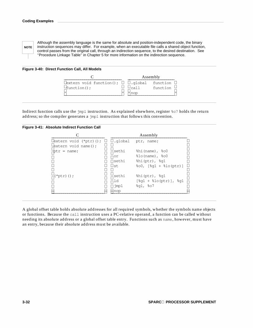
Coding Examples
NOTE
Although the assembly language is the same for absolute and position-independent code, the binaryinstruction sequences may differ. For example, when an executable file calls a shared object function,control passes from the original call, through an indirection sequence, to the desired destination. See‘‘Procedure Linkage Table’’ in Chapter 5 for more information on the indirection sequence.
Figure 3-40: Direct Function Call, All Models
C Assembly_ ___________________________ _ ______________________e x t e r n v o i d f u n c t i o n ( ) ; . g l o b a l f u n c t i o nf u n c t i o n ( ) ; c a l l f u n c t i o n
n o p_ ___________________________ _ ______________________
Indirect function calls use the j m p l instruction. As explained elsewhere, register % o 7 holds the returnaddress; so the compiler generates a j m p l instruction that follows this convention.
Figure 3-41: Absolute Indirect Function Call
C Assembly_ _________________________ _ ____________________________________e x t e r n v o i d ( * p t r ) ( ) ; . g l o b a l p t r , n a m e ;e x t e r n v o i d n a m e ( ) ;p t r = n a m e ; s e t h i % h i ( n a m e ) , % o 0
o r % l o ( n a m e ) , % o 0s e t h i % h i ( p t r ) , % g 1s t % o 0 , [ % g 1 + % l o ( p t r ) ]
( * p t r ) ( ) ; s e t h i % h i ( p t r ) , % g 1l d [ % g 1 + % l o ( p t r ) ] , % g 1j m p l % g 1 , % o 7n o p_ _________________________ _ ____________________________________
A global offset table holds absolute addresses for all required symbols, whether the symbols name objectsor functions. Because the c a l l instruction uses a PC-relative operand, a function can be called withoutneeding its absolute address or a global offset table entry. Functions such as n a m e, however, must havean entry, because their absolute address must be available.
3-32 SPARC PROCESSOR SUPPLEMENT

Coding Examples
Figure 3-42: Small Model Position-Independent Indirect Function Call
C Assembly_ _________________________ _ ________________________________e x t e r n v o i d ( * p t r ) ( ) ; . g l o b a l p t r , n a m ee x t e r n v o i d n a m e ( ) ;p t r = n a m e ; l d [ % l 7 + n a m e ] , % o 0
l d [ % l 7 + p t r ] , % g 1s t % o 0 , [ % g 1 ]
( * p t r ) ( ) ; l d [ % l 7 + p t r ] , % g 1l d [ % g 1 ] , % g 1j m p l % g 1 , % o 7n o p_ _________________________ _ ________________________________
Figure 3-43: Large Model Position-Independent Indirect Function Call
C Assembly_ _________________________ _ _______________________________e x t e r n v o i d ( * p t r ) ( ) ; . g l o b a l p t r , n a m ee x t e r n v o i d n a m e ( ) ;p t r = n a m e ; s e t h i % h i ( n a m e ) , % o 0
o r % l o ( n a m e ) , % o 0l d [ % l 7 + % o 0 ] , % o 0s e t h i % h i ( p t r ) , % g 1o r % l o ( p t r ) , % g 1l d [ % l 7 + % g 1 ] , % g 1s t % o 0 , [ % g 1 ]
( * p t r ) ( ) ; s e t h i % h i ( p t r ) , % g 1o r % l o ( p t r ) , % g 1l d [ % l 7 + % g 1 ] , % g 1l d [ % g 1 ] , % g 1j m p l % g 1 , % o 7n o p_ _________________________ _ _______________________________
Branching
Programs use branch instructions to control their execution flow. As defined by the architecture, branchinstructions hold a PC-relative value with a 16 megabyte range, allowing a jump to locations up to 8megabytes away in either direction.
LOW-LEVEL SYSTEM INFORMATION 3-33

Coding Examples
Figure 3-44: Branch Instruction, All Models
C Assembly_ ________________________ _ ________________________l a b e l : . L 0 1 :
. . . . . .g o t o l a b e l ; b a . L 0 1
n o p_ ________________________ _ ________________________
C s w i t c h statements provide multiway selection. When the c a s e labels of a s w i t c h statement satisfygrouping constraints, the compiler implements the selection with an address table. The following exam-ples use several simplifying conventions to hide irrelevant details:
The selection expression resides in local register % l 0;
c a s e label constants begin at zero;
c a s e labels, d e f a u l t, and the address table use assembly names . L c a s ei, . L d e f, and . L t a b,respectively.
Address table entries for absolute code contain virtual addresses; the selection code extracts an entry’svalue and jumps to that address. Position-independent table entries hold offsets; the selection code com-putes a destination’s absolute address.
Figure 3-45: Absolute s w i t c h Code
C Assembly_ _____________ _ ___________________________________________s w i t c h ( j ) s u b c c % l 0 , 4 , % g 0{ b g u . L d e fc a s e 0 : s l l % l 0 , 2 , % l 0
. . . s e t h i % h i ( . L t a b ) , % o 1c a s e 2 : o r % o 1 , % l o ( . L t a b ) , % o 1
. . . l d [ % l 0 + % o 1 ] , % l 0c a s e 3 : j m p l % l 0 , % g 0
. . . n o pd e f a u l t : . L t a b : . w o r d . L c a s e 0
. . . . w o r d . L d e f} . w o r d . L c a s e 2
. w o r d . L c a s e 3_ _____________ _ ___________________________________________
Figure 3-46: Position-Independent s w i t c h Code
C Assembly_ _____________ _ ________________________________________________s w i t c h ( j ) s u b c c % l 0 , 4 , % g 0{ b g u . L d e fc a s e 0 : s l l % l 0 , 2 , % l 0
. . . 1 : c a l l 2 f
3-34 SPARC PROCESSOR SUPPLEMENT

Coding Examples
Figure 3-46: Position-Independent s w i t c h Code (continued )
c a s e 2 : s e t h i % h i ( . L t a b - 1 b ) , % g 1. . . 2 : o r % g 1 , % l o ( . L t a b - 1 b ) , % g 1
c a s e 3 : a d d % l 0 , % g 1 , % l 0. . . l d [ % o 7 + % l 0 ] , % l 0
d e f a u l t : j m p l % o 7 + % l 0 , % g 0. . . n o p
} . L t a b : . w o r d . L c a s e 0 - 1 b. w o r d . L d e f - 1 b. w o r d . L c a s e 2 - 1 b. w o r d . L c a s e 3 - 1 b_ _____________ _ ________________________________________________
C Stack Frame
Figure 3-47 shows the C stack frame organization. It conforms to the standard stack frame with desig-nated roles for unspecified areas in the standard frame.
Figure 3-47: C Stack Frame
Base Offset Contents Frame_ __________________________________________________________% f p –1 y words local space: High addresses
automatic variables. . .
% f p − 4y other addressable objects% s p 92+ 4x
_ ________________________________ _______________________________x words compiler scratch space:
temporaries,register save area
% s p 92 outgoing arguments 6, . . ._ _______________________________outgoing argument 5
. . .% s p 68 outgoing argument 0_ _______________________________% s p 64 s t r u c t/u n i o n return pointer
_ _______________________________
Current
% s p 0 16-word window save area Low addresses_ __________________________________________________________
A C stack frame doesn’t normally change size during execution. The exception is dynamically allocatedstack memory, discussed below. By convention, a function allocates automatic (local) variables in the topof its frame and references them as negative offsets from % f p. Its incoming arguments reside in the previ-ous frame, referenced as positive offsets from % f p.
LOW-LEVEL SYSTEM INFORMATION 3-35

Coding Examples
Variable Argument List
Previous sections describe the rules for passing arguments. Unfortunately, some otherwise portable Cprograms depend on the argument passing scheme, implicitly assuming that 1) all arguments reside onthe stack, and 2) arguments appear in increasing order on the stack. Programs that make these assump-tions never have been portable, but they have worked on many machines. They do not work on SPARCbecause the first 6 argument words reside in registers. Portable C programs should use the facilitiesdefined in the header files < s t d a r g . h > or < v a r a r g s . h > to deal with variable argument lists (on SPARCand other machines as well).
When a function uses < s t d a r g . h > facilities, the compiler generates code in that function to move itsregister arguments to the stack’s argument save area, thereafter treating them as regular stack objects.Argument registers are allocated in word order, meaning the stack locations for multi-word floating-point arguments may not be aligned properly. Thus a pointer to d o u b l e might sometimes reference anunaligned object. Consequently, the compiler generates code to dereference ‘‘unknown’’ pointers oneword at a time.
Figure 3-48: Argument Stack Positions
Call Argument Original Stack_ ___________________________________________________word 0, 1 . 4 1 4 % i 0 % f p + 6 8word 1, 1 . 4 1 4 % i 1 % f p + 7 21 % i 2 % f p + 7 6word 0, 2 . 9 9 8 e 1 0 % i 3 % f p + 8 0word 1, 2 . 9 9 8 e 1 0 % i 4 % f p + 8 4word 0, 2 . 7 1 8 % i 5 % f p + 8 8
h ( 1 . 4 1 4 , 1 ,2 . 9 9 8 e 1 0 ,2 . 7 1 8 ) ;
word 1, 2 . 7 1 8 % f p + 9 2 % f p + 9 2_ ___________________________________________________
The save area for 1 . 4 1 4 is not doubleword aligned, because its offset, + 6 8, is not a multiple of 8. Thusthe compiler would load and store the value one word at a time. On the other hand, 2 . 7 1 8 resides at% f p + 8 8, and the compiler can generate doubleword loads and stores. Alignments assume % f p and % s phold doubleword addresses.
Allocating Stack Space Dynamically
Unlike some other languages, C does not need dynamic stack allocation within a stack frame. Frames areallocated dynamically on the program stack, depending on program execution, but individual stackframes can have static sizes. Nonetheless, the architecture supports dynamic allocation for thoselanguages that require it, and the standard calling sequence and stack frame support it as well. Thuslanguages that need dynamic stack frame sizes can call C functions, and vice versa.
Figure 3-47 shows the layout of the C stack frame. The double line divides the area referenced with theframe pointer from the area referenced with the stack pointer. Dynamic space is allocated above the lineas a downward growing heap whose size changes as required. Typical C functions have no space in theheap. All areas below the double line in the current frame have a known size to the compiler. Dynamicstack allocation thus takes the following steps.
3-36 SPARC PROCESSOR SUPPLEMENT
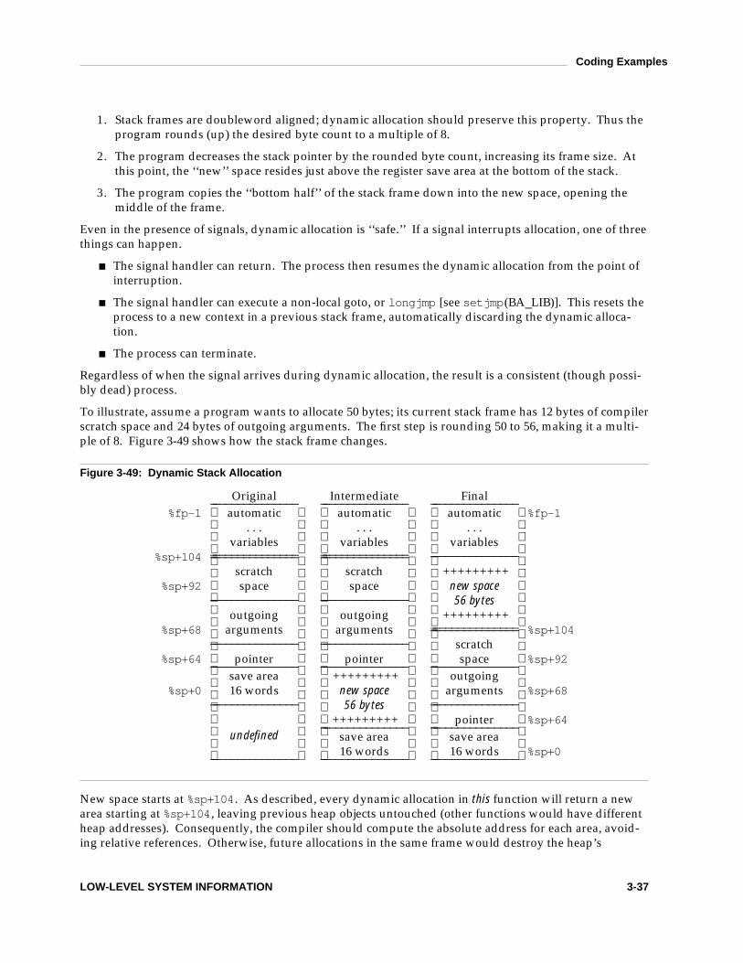
Coding Examples
1 . Stack frames are doubleword aligned; dynamic allocation should preserve this property. Thus theprogram rounds (up) the desired byte count to a multiple of 8.
2 . The program decreases the stack pointer by the rounded byte count, increasing its frame size. Atthis point, the ‘‘new’’ space resides just above the register save area at the bottom of the stack.
3 . The program copies the ‘‘bottom half’’ of the stack frame down into the new space, opening themiddle of the frame.
Even in the presence of signals, dynamic allocation is ‘‘safe.’’ If a signal interrupts allocation, one of threethings can happen.
The signal handler can return. The process then resumes the dynamic allocation from the point ofinterruption.
The signal handler can execute a non-local goto, or l o n g j m p [see s e t j m p(BA_LIB)]. This resets theprocess to a new context in a previous stack frame, automatically discarding the dynamic alloca-tion.
The process can terminate.
Regardless of when the signal arrives during dynamic allocation, the result is a consistent (though possi-bly dead) process.
To illustrate, assume a program wants to allocate 50 bytes; its current stack frame has 12 bytes of compilerscratch space and 24 bytes of outgoing arguments. The first step is rounding 50 to 56, making it a multi-ple of 8. Figure 3-49 shows how the stack frame changes.
Figure 3-49: Dynamic Stack Allocation
Original Intermediate Final_ ______________ _ ______________ _ ______________% f p - 1 automatic automatic automatic % f p - 1
. . . . . . . . .variables variables variables
% s p + 1 0 4_ _______________ ______________ _ _______________ ______________ _ ______________
scratch scratch +++++++++% s p + 9 2 space space new space
_ ______________ _ ______________ 56 bytesoutgoing outgoing +++++++++
% s p + 6 8 arguments arguments _ _______________ ______________ % s p + 1 0 4_ ______________ _ ______________ scratch
% s p + 6 4 pointer pointer space % s p + 9 2_ ______________ _ ______________ _ ______________save area +++++++++ outgoing
% s p + 0 16 words new space arguments % s p + 6 8_ ______________ 56 bytes _ ______________
+++++++++ pointer % s p + 6 4_ ______________ _ ______________save area save areaundefined16 words 16 words % s p + 0_ ______________ _ ______________ _ ______________
New space starts at % s p + 1 0 4. As described, every dynamic allocation in this function will return a newarea starting at % s p + 1 0 4, leaving previous heap objects untouched (other functions would have differentheap addresses). Consequently, the compiler should compute the absolute address for each area, avoid-ing relative references. Otherwise, future allocations in the same frame would destroy the heap’s
LOW-LEVEL SYSTEM INFORMATION 3-37

Coding Examples
integrity.
Existing stack objects reside at fixed offsets from the frame and stack pointers; stack heap allocationpreserves those offsets. Objects relative to the frame pointer don’t move. Objects relative to the stackpointer move, but their % s p-relative positions do not change. Accordingly, compilers arrange not to pub-licize the absolute address of any object in the bottom half of the stack frame (in a way that violates thescope rules). % s p-relative references stay valid after dynamic allocation, but absolute addresses do not.
No special code is needed to free dynamically allocated stack memory. The function return resets thestack pointer and removes the entire stack frame, including the heap, from the stack. Naturally, a pro-gram should not reference heap objects after they have gone out of scope.
3-38 SPARC PROCESSOR SUPPLEMENT

4 OBJECT FILES
ELF Header 4-1Machine Information 4-1
Sections 4-2Special Sections 4-2Symbol Table 4-2
Symbol Values 4-2
Relocation 4-3Relocation Types 4-3
Table of Contents i

ELF Header
Machine Information
For file identification in e _ i d e n t, SPARC requires the following values.
Figure 4-1: SPARC Identification, e _ i d e n t
Position Value_ _________________________________e _ i d e n t [ E I _ C L A S S ] E L F C L A S S 3 2e _ i d e n t [ E I _ D A T A ] E L F D A T A 2 M S B_ _________________________________
Processor identification resides in the ELF header’s e _ m a c h i n e member and must have the value 2,defined as the name E M _ S P A R C.
The ELF header’s e _ f l a g s member holds bit flags associated with the file. SPARC defines no flags; sothis member contains zero.
OBJECT FILES 4-1

Sections
Special Sections
Various sections hold program and control information. Sections in the list below are used by the systemand have the indicated types and attributes.
Figure 4-2: Special Sections
Name Type Attributes_ _______________________________________________________________. g o t S H T _ P R O G B I T S S H F _ A L L O C + S H F _ W R I T E. p l t S H T _ P R O G B I T S S H F _ A L L O C + S H F _ W R I T E + S H F _ E X E C I N S T R. s d a t a S H T _ P R O G B I T S S H F _ A L L O C + S H F _ W R I T E_ _______________________________________________________________
. g o t This section holds the global offset table. See ‘‘Coding Examples’’ in Chapter 3 and ‘‘GlobalOffset Table’’ in Chapter 5 for more information.
. p l t This section holds the procedure linkage table. See ‘‘Procedure Linkage Table’’ in Chapter 5for more information.
. s d a t a This section holds initialized data that contribute to the program’s memory image. The dataare addressable by the short-form address convention.
Symbol Table
Symbol Values
If an executable file contains a reference to a function defined in one of its associated shared objects, thesymbol table section for that file will contain an entry for that symbol. The s t _ s h n d x member of thatsymbol table entry contains S H N _ U N D E F. This informs the dynamic linker that the symbol definition forthat function is not contained in the executable file itself. If that symbol has been allocated a procedurelinkage table entry in the executable file, and the s t _ v a l u e member for that symbol table entry is non-zero, the value will contain the virtual address of the first instruction of that procedure linkage tableentry. Otherwise, the s t _ v a l u e member contains zero. This procedure linkage table entry address isused by the dynamic linker in resolving references to the address of the function. See ‘‘FunctionAddresses’’ in Chapter 5 for details.
4-2 SPARC PROCESSOR SUPPLEMENT

Relocation
Relocation Types
An overview of the instruction and data formats from The SPARC Architecture Manual makes relocationeasier to understand. Relocation entries describe how to alter the following instruction and data fields(bit numbers appear in the lower box corners).
Figure 4-3: Relocatable Fields
byte87 0
half1615 0
word3231 0
31disp30
29 0
31disp22
21 0
31imm22
21 0
31simm13
12 0
3-word PLT entry31 0
31 0
31 0
Calculations below assume the actions are transforming a relocatable file into either an executable or ashared object file. Conceptually, the link editor merges one or more relocatable files to form the output.It first decides how to combine and locate the input files, then updates the symbol values, and finally per-forms the relocation. Relocations applied to executable or shared object files are similar and accomplishthe same result. Descriptions below use the following notation.
A This means the addend used to compute the value of the relocatable field.
B This means the base address at which a shared object has been loaded into memory during execu-tion. Generally, a shared object file is built with a 0 base virtual address, but the executionaddress will be different. See ‘‘Program Header’’ in the System V ABI for more informationabout the base address.
OBJECT FILES 4-3

Relocation
G This means the offset into the global offset table at which the address of the relocation entry’ssymbol will reside during execution. See ‘‘Coding Examples’’ in Chapter 3 and ‘‘Global OffsetTable’’ in Chapter 5 for more information.
L This means the place (section offset or address) of the procedure linkage table entry for a symbol.A procedure linkage table entry redirects a function call to the proper destination. The link edi-tor builds the initial procedure linkage table, and the dynamic linker modifies the entries duringexecution. See ‘‘Procedure Linkage Table’’ in Chapter 5 for more information.
P This means the place (section offset or address) of the storage unit being relocated (computedusing r _ o f f s e t).
S This means the value of the symbol whose index resides in the relocation entry.
Relocation entries apply to bytes (byte8), halfwords (half16), or words (the others). In any case, ther _ o f f s e t value designates the offset or virtual address of the first byte of the affected storage unit. Therelocation type specifies which bits to change and how to calculate their values. SPARC uses onlyE l f 3 2 _ R e l a relocation entries with explicit addends. Thus the r _ a d d e n d member serves as the reloca-tion addend.
NOTE
Field names in the following table tell whether the relocation type checks for ‘‘overflow.’’ A calculatedrelocation value may be larger than the intended field, and a relocation type may verify (V) the value fitsor truncate (T) the result. As an example, V-simm13 means the the computed value may not havesignificant, non-zero bits outside the simm13 field.
Figure 4-4: Relocation Types
Name Value Field Calculation_ _____________________________________________________________R _ S P A R C _ N O N E 0 none noneR _ S P A R C _ 8 1 V-byte8 S + AR _ S P A R C _ 1 6 2 V-half16 S + AR _ S P A R C _ 3 2 3 V-word32 S + AR _ S P A R C _ D I S P 8 4 V-byte8 S + A - PR _ S P A R C _ D I S P 1 6 5 V-half16 S + A - PR _ S P A R C _ D I S P 3 2 6 V-word32 S + A - PR _ S P A R C _ W D I S P 3 0 7 V-disp30 ( S + A - P ) > > 2R _ S P A R C _ W D I S P 2 2 8 V-disp22 ( S + A - P ) > > 2R _ S P A R C _ H I 2 2 9 T-imm22 ( S + A ) > > 1 0R _ S P A R C _ 2 2 1 0 V-imm22 S + AR _ S P A R C _ 1 3 1 1 V-simm13 S + AR _ S P A R C _ L O 1 0 1 2 T-simm13 ( S + A ) & 0 x 3 f fR _ S P A R C _ G O T 1 0 1 3 T-simm13 G & 0 x 3 f fR _ S P A R C _ G O T 1 3 1 4 V-simm13 GR _ S P A R C _ G O T 2 2 1 5 T-imm22 G > > 1 0R _ S P A R C _ P C 1 0 1 6 T-simm13 ( S + A - P ) & 0 x 3 f fR _ S P A R C _ P C 2 2 1 7 V-disp22 ( S + A - P ) > > 1 0R _ S P A R C _ W P L T 3 0 1 8 V-disp30 ( L + A - P ) > > 2R _ S P A R C _ C O P Y 1 9 none noneR _ S P A R C _ G L O B _ D A T 2 0 V-word32 S + AR _ S P A R C _ J M P _ S L O T 2 1 none see below
4-4 SPARC PROCESSOR SUPPLEMENT

Relocation
Figure 4-4: Relocation Types (continued )
R _ S P A R C _ R E L A T I V E 2 2 V-word32 B + AR _ S P A R C _ U A 3 2 2 3 V-word32 S + A_ _____________________________________________________________
Some relocation types have semantics beyond simple calculation.
R _ S P A R C _ G O T 1 0 This relocation type resembles R _ S P A R C _ L O 1 0, except it refers to the address ofthe symbol’s global offset table entry and additionally instructs the link editor tobuild a global offset table.
R _ S P A R C _ G O T 1 3 This relocation type resembles R _ S P A R C _ 1 3, except it refers to the address of thesymbol’s global offset table entry and additionally instructs the link editor tobuild a global offset table.
R _ S P A R C _ G O T 2 2 This relocation type resembles R _ S P A R C _ 2 2, except it refers to the address of thesymbol’s global offset table entry and additionally instructs the link editor tobuild a global offset table.
R _ S P A R C _ W P L T 3 0 This relocation type resembles R _ S P A R C _ W D I S P 3 0, except it refers to the addressof the symbol’s procedure linkage table entry and additionally instructs the linkeditor to build a procedure linkage table.
R _ S P A R C _ C O P Y The link editor creates this relocation type for dynamic linking. Its offsetmember refers to a location in a writable segment. The symbol table indexspecifies a symbol that should exist both in the current object file and in a sharedobject. During execution, the dynamic linker copies data associated with theshared object’s symbol to the location specified by the offset.
R _ S P A R C _ G L O B _ D A T This relocation type resembles R _ S P A R C _ 3 2, except it is used to set a global offsettable entry to the address of the specified symbol. The special relocation typeallows one to determine the correspondence between symbols and global offsettable entries.
R _ S P A R C _ J M P _ S L O T The link editor creates this relocation type for dynamic linking. Its offsetmember gives the location of a procedure linkage table entry. The dynamiclinker modifies the procedure linkage table entry to transfer control to the desig-nated symbol’s address [see ‘‘Procedure Linkage Table’’ in Chapter 5].
R _ S P A R C _ R E L A T I V E The link editor creates this relocation type for dynamic linking. Its offsetmember gives a location within a shared object that contains a value representinga relative address. The dynamic linker computes the corresponding virtualaddress by adding the virtual address at which the shared object was loaded tothe relative address. Relocation entries for this type must specify 0 for the sym-bol table index.
R _ S P A R C _ U A 3 2 This relocation type resembles R _ S P A R C _ 3 2, except it refers to an unalignedword. That is, the ‘‘word’’ to be relocated must be treated as four separate byteswith arbitrary alignment, not as a word aligned according to the architecturerequirements.
OBJECT FILES 4-5

5 PROGRAM LOADING AND DYNAMIC LINKING
Program Loading 5-1
Dynamic Linking 5-5Dynamic Section 5-5Global Offset Table 5-5Function Addresses 5-6Procedure Linkage Table 5-7Program Interpreter 5-10
Table of Contents i

Program Loading
As the system creates or augments a process image, it logically copies a file’s segment to a virtualmemory segment. When—and if—the system physically reads the file depends on the program’s execu-tion behavior, system load, etc. A process does not require a physical page unless it references the logicalpage during execution, and processes commonly leave many pages unreferenced. Therefore delayingphysical reads frequently obviates them, improving system performance. To obtain this efficiency inpractice, executable and shared object files must have segment images whose file offsets and virtualaddresses are congruent, modulo the page size.
Virtual addresses and file offsets for SPARC segments are congruent modulo 64 K (0 x 1 0 0 0 0) or largerpowers of 2. Because 64 KB is the maximum page size, the files will be suitable for paging regardless ofphysical page size.
Figure 5-1: Executable File
File Offset File Virtual Address_ ______________________0 ELF header_ ______________________
Program header table_ ______________________Other information_ ______________________
0 x 1 0 0 Text segment 0 x 1 0 1 0 0. . .
0 x 2 b e 0 0 bytes 0 x 3 b e f f_ ______________________0 x 2 b f 0 0 Data segment 0 x 4 b f 0 0
. . .0 x 4 e 0 0 bytes 0 x 5 0 c f f_ ______________________
0 x 3 0 d 0 0 Other information. . .
_ ______________________
Figure 5-2: Program Header Segments
Member Text Data_ __________________________________________p _ t y p e P T _ L O A D P T _ L O A Dp _ o f f s e t 0 x 1 0 0 0 x 2 b f 0 0p _ v a d d r 0 x 1 0 1 0 0 0 x 4 b f 0 0p _ p a d d r unspecified unspecifiedp _ f i l e s z 0 x 2 b e 0 0 0 x 4 e 0 0p _ m e m s z 0 x 2 b e 0 0 0 x 5 e 2 4p _ f l a g s P F _ R + P F _ X P F _ R + P F _ W + P F _ Xp _ a l i g n 0 x 1 0 0 0 0 0 x 1 0 0 0 0_ __________________________________________
Although the example’s file offsets and virtual addresses are congruent modulo 64 K for both text anddata, up to four file pages hold impure text or data (depending on page size and file system block size).
The first text page contains the ELF header, the program header table, and other information.
PROGRAM LOADING AND DYNAMIC LINKING 5-1

Program Loading
The last text page holds a copy of the beginning of data.
The first data page has a copy of the end of text.
The last data page may contain file information not relevant to the running process.
Logically, the system enforces the memory permissions as if each segment were complete and separate;segments’ addresses are adjusted to ensure each logical page in the address space has a single set of per-missions. In the example above, the region of the file holding the end of text and the beginning of datawill be mapped twice: at one virtual address for text and at a different virtual address for data.
The end of the data segment requires special handling for uninitialized data, which the system defines tobegin with zero values. Thus if a file’s last data page includes information not in the logical memorypage, the extraneous data must be set to zero, not the unknown contents of the executable file. ‘‘Impuri-ties’’ in the other three pages are not logically part of the process image; whether the system expungesthem is unspecified. The memory image for this program follows, assuming 4 KB (0 x 1 0 0 0) pages.
Figure 5-3: Process Image Segments
Virtual Address Contents Segment_ ___________________0 x 1 0 0 0 0 Header padding
0 x 1 0 0 bytes_ ___________________0 x 1 0 1 0 0 Text segment
. . .
0 x 2 b e 0 0 bytes_ ___________________0 x 3 b f 0 0 Data padding
0 x 1 0 0 bytes
Text
_ ___________________
_ ___________________0 x 4 b 0 0 0 Text padding
0 x f 0 0 bytes_ ___________________0 x 4 b f 0 0 Data segment
. . .
0 x 4 e 0 0 bytes_ ___________________0 x 5 0 d 0 0 Uninitialized data
0 x 1 0 2 4 zero bytes_ ___________________0 x 5 1 d 2 4 Page padding
0 x 2 d c zero bytes
Data
_ ___________________
One aspect of segment loading differs between executable files and shared objects. Executable file seg-ments typically contain absolute code [see ‘‘Coding Examples’’ in Chapter 3]. To let the process executecorrectly, the segments must reside at the virtual addresses used to build the executable file. Thus thesystem uses the p _ v a d d r values unchanged as virtual addresses.
5-2 SPARC PROCESSOR SUPPLEMENT

Program Loading
On the other hand, shared object segments typically contain position-independent code. This lets asegment’s virtual address change from one process to another, without invalidating execution behavior.Though the system chooses virtual addresses for individual processes, it maintains the segments’ relativepositions . Because position-independent code uses relative addressing between segments, the differencebetween virtual addresses in memory must match the difference between virtual addresses in the file.The following table shows possible shared object virtual address assignments for several processes, illus-trating constant relative positioning. The table also illustrates the base address computations.
Figure 5-4: Example Shared Object Segment Addresses
Source Text Data Base Address_ ___________________________________________________File 0 x 2 0 0 0 x 2 a 4 0 0 0 x 0Process 1 0 x c 0 0 0 0 2 0 0 0 x c 0 0 2 a 4 0 0 0 x c 0 0 0 0 0 0 0Process 2 0 x c 0 0 1 0 2 0 0 0 x c 0 0 3 a 4 0 0 0 x c 0 0 1 0 0 0 0Process 3 0 x d 0 0 2 0 2 0 0 0 x d 0 0 4 a 4 0 0 0 x d 0 0 2 0 0 0 0Process 4 0 x d 0 0 3 0 2 0 0 0 x d 0 0 5 a 4 0 0 0 x d 0 0 3 0 0 0 0_ ___________________________________________________
PROGRAM LOADING AND DYNAMIC LINKING 5-3

Dynamic Linking
Dynamic Section
Dynamic section entries give information to the dynamic linker. Some of this information is processor-specific, including the interpretation of some entries in the dynamic structure.
D T _ P L T G O T On SPARC, this entry’s d _ p t r member gives the address of the first entry in the pro-cedure linkage table. As described below, the first entry is special, and the dynamiclinker must know its address.
D T _ J M P _ R E L As explained in the System V ABI, this entry is associated with a table of relocationentries for the procedure linkage table. For the SPARC processor, this entry is manda-tory both for executable and shared object files. Moreover, the relocation table’s entriesmust have a one-to-one correspondence with the procedure linkage table. See ‘‘Pro-cedure Linkage Table’’ below for more information.
Global Offset Table
Position-independent code cannot, in general, contain absolute virtual addresses. Global offset tableshold absolute addresses in private data, thus making the addresses available without compromising theposition-independence and sharability of a program’s text. A program references its global offset tableusing position-independent addressing and extracts absolute values, thus redirecting position-independent references to absolute locations.
Initially, the global offset table holds information as required by its relocation entries [see ‘‘Relocation’’ inChapter 4]. After the system creates memory segments for a loadable object file, the dynamic linkerprocesses the relocation entries, some of which will be type R _ S P A R C _ G L O B _ D A T referring to the globaloffset table. The dynamic linker determines the associated symbol values, calculates their absoluteaddresses, and sets the appropriate memory table entries to the proper values. Although the absoluteaddresses are unknown when the link editor builds an object file, the dynamic linker knows theaddresses of all memory segments and can thus calculate the absolute addresses of the symbols containedtherein.
If a program requires direct access to the absolute address of a symbol, that symbol will have a globaloffset table entry. Because the executable file and shared objects have separate global offset tables, asymbol’s address may appear in several tables. The dynamic linker processes all the global offset tablerelocations before giving control to any code in the process image, thus ensuring the absolute addressesare available during execution.
The table’s entry zero is reserved to hold the address of the dynamic structure, referenced with the sym-bol _ D Y N A M I C. This allows a program, such as the dynamic linker, to find its own dynamic structurewithout having yet processed its relocation entries. This is especially important for the dynamic linker,because it must initialize itself without relying on other programs to relocate its memory image.
The system may choose different memory segment addresses for the same shared object in different pro-grams; it may even choose different library addresses for different executions of the same program.Nonetheless, memory segments do not change addresses once the process image is established. As longas a process exists, its memory segments reside at fixed virtual addresses.
A global offset table’s format and interpretation are processor-specific. For SPARC, the symbol_ G L O B A L _ O F F S E T _ T A B L E _ may be used to access the table.
5-4 SPARC PROCESSOR SUPPLEMENT

Dynamic Linking
Figure 5-5: Global Offset Table
e x t e r n E l f 3 2 _ A d d r _ G L O B A L _ O F F S E T _ T A B L E _ [ ] ;
The symbol _ G L O B A L _ O F F S E T _ T A B L E _ may reside in the middle of the . g o t section, allowing both nega-tive and non-negative ‘‘subscripts’’ into the array of addresses.
Function Addresses
References to the address of a function from an executable file and the shared objects associated with itmight not resolve to the same value. References from within shared objects will normally be resolved bythe dynamic linker to the virtual address of the function itself. References from within the executable fileto a function defined in a shared object will normally be resolved by the link editor to the address of theprocedure linkage table entry for that function within the executable file.
To allow comparisons of function addresses to work as expected, if an executable file references a func-tion defined in a shared object, the link editor will place the address of the procedure linkage table entryfor that function in its associated symbol table entry. [See ‘‘Symbol Values’’ in Chapter 4]. The dynamiclinker treats such symbol table entries specially. If the dynamic linker is searching for a symbol, andencounters a symbol table entry for that symbol in the executable file, it normally follows the rules below.
1 . If the s t _ s h n d x member of the symbol table entry is not S H N _ U N D E F, the dynamic linker has founda definition for the symbol and uses its s t _ v a l u e member as the symbol’s address.
2 . If the s t _ s h n d x member is S H N _ U N D E F and the symbol is of type S T T _ F U N C and the s t _ v a l u emember is not zero, the dynamic linker recognizes this entry as special and uses the s t _ v a l u emember as the symbol’s address.
3 . Otherwise, the dynamic linker considers the symbol to be undefined within the executable file andcontinues processing.
Some relocations are associated with procedure linkage table entries. These entries are used for directfunction calls rather than for references to function addresses. These relocations are not treated in thespecial way described above because the dynamic linker must not redirect procedure linkage table entriesto point to themselves.
Procedure Linkage Table
Much as the global offset table redirects position-independent address calculations to absolute locations,the procedure linkage table redirects position-independent function calls to absolute locations. The linkeditor cannot resolve execution transfers (such as function calls) from one executable or shared object toanother. Consequently, the link editor arranges to have the program transfer control to entries in the pro-cedure linkage table. On SPARC, procedure linkage tables reside in private data. The dynamic linkerdetermines the destinations’ absolute addresses and modifies the procedure linkage table’s memoryimage accordingly. The dynamic linker thus can redirect the entries without compromising the position-independence and sharability of the program’s text. Executable files and shared object files have separate
PROGRAM LOADING AND DYNAMIC LINKING 5-5

Dynamic Linking
procedure linkage tables.
The first four procedure linkage table entries are reserved. (The original contents of these entries areunspecified, despite the example below.) Each entry in the table occupies 3 words (12 bytes), and the lasttable entry must be followed by a n o p instruction. As mentioned before, a relocation table is associatedwith the procedure linkage table. The D T _ J M P _ R E L entry in the _ D Y N A M I C array gives the location of thefirst relocation entry. The relocation table’s entries parallel the procedure linkage table in a one-to-onecorrespondence. That is, relocation table entry 0 applies to procedure linkage table entry 0, and so on.With the exception of the first four entries, the relocation type will be R _ S P A R C _ J M P _ S L O T, the relocationoffset will specify the address of first byte of the associated procedure linkage table entry, and the symboltable index will reference the appropriate symbol.
To illustrate procedure linkage tables, the figure below shows four entries: two of the four initial reservedentries, a third to call n a m e 1, and a fourth to call n a m e 2. The example assumes the entry for n a m e 2 is thetable’s last entry and shows the following n o p instruction. The left column shows the instructions fromthe object file before dynamic linking. The right column demonstrates a possible way the dynamic linkermight ‘‘fix’’ the procedure linkage table entries.
Figure 5-6: Procedure Linkage Table Example
Object File Memory Segment_ ________________________________________________________________. P L T 0 : . P L T 0 :
u n i m p s a v e % s p , - 6 4 , % s pu n i m p c a l l dynamic-linkeru n i m p n o p
. P L T 1 : . P L T 1 :u n i m p . w o r d identificationu n i m p u n i m pu n i m p u n i m p. . . . . ._ ________________________________________________________________. . . . . .
. P L T 1 0 1 : . P L T 1 0 1 :s e t h i ( . - . P L T 0 ) , % g 1 s e t h i ( . - . P L T 0 ) , % g 1b a , a . P L T 0 s e t h i % h i ( n a m e 1 ) , % g 1n o p j m p l % g 1 + % l o ( n a m e 1 ) , % g 0
. P L T 1 0 2 : . P L T 1 0 2 :s e t h i ( . - . P L T 0 ) , % g 1 s e t h i ( . - . P L T 0 ) , % g 1b a , a . P L T 0 s e t h i % h i ( n a m e 2 ) , % g 1n o p j m p l % g 1 + % l o ( n a m e 2 ) , % g 0_ ________________________________________________________________n o p n o p_ ________________________________________________________________
Following the steps below, the dynamic linker and the program ‘‘cooperate’’ to resolve symbolic refer-ences through the procedure linkage table. Again, the steps described below are for explanation only.The precise execution-time behavior of the dynamic linker is not specified.
1 . When first creating the memory image of the program, the dynamic linker changes the initial pro-cedure linkage table entries, making them transfer control to one of the dynamic linker’s own rou-tines: dynamic-linker above. It also stores a word of identification information in the second entry.When it receives control, it can examine this word to determine what object called it.
5-6 SPARC PROCESSOR SUPPLEMENT

Dynamic Linking
2 . All other procedure linkage table entries initially transfer to the first entry, allowing the dynamiclinker to can gain control at the first execution of each table entry. For illustration, assume the pro-gram calls n a m e 1, which transfers control to the label . P L T 1 0 1.
3 . The s e t h i instruction computes the distance between the current and the initial procedure linkagetable entries, . P L T 1 0 1 and . P L T 0, respectively. This value occupies the most significant 22 bits ofthe % g 1 register. In this example, % g 1 will contain 0 x 1 2 f 0 0 0 when the dynamic linker receivescontrol.
4 . Next, the b a , a instruction jumps to . P L T 0, which then establishes a stack frame and calls thedynamic linker.
5 . Using the identification value, the dynamic linker finds its data structures associated with the objectin question, including the relocation table.
6 . By shifting the % g 1 value and dividing by the size of each procedure linkage table entry, thedynamic linker computes the index of the relocation entry for n a m e 1. Relocation entry 101 willhave type R _ S P A R C _ J M P _ S L O T, its offset will specify the address of . P L T 1 0 1, and its symbol tableindex will reference n a m e 1.
7 . Knowing this, the dynamic linker finds the symbol’s ‘‘real’’ value, unwinds the stack, modifies theprocedure linkage table entry, and transfers control to the desired destination.
Although the dynamic linker is not required to create the instruction sequences under the ‘‘Memory Seg-ment’’ column, it might. Assuming it actually did, several points deserve further explanation.
To make the code re-entrant, the procedure linkage table’s instructions must be changed in a partic-ular sequence. That is, if the dynamic linker is ‘‘fixing’’ a function’s procedure linkage table entryand a signal arrives, the signal handling code must be able to call the original function with predict-able (and correct) results.
The dynamic linker must change two words to convert an entry; it can update each word atomi-cally. Re-entrancy can be achieved by first overwriting the n o p with the j m p l instruction, and thenpatching the b a , a to be s e t h i. If a re-entrant function call occurs between the two word updates,the j m p l will reside in the delay slot of the b a , a instruction, which annuls the delay instruction’seffects. Consequently, the dynamic linker gains control a second time. Although both invocationsof the dynamic linker modify the same procedure linkage table entry, their changes do not interferewith each other.
The first s e t h i instruction of a procedure linkage table entry can fill the delay slot of the previousentry’s j m p l instruction. Although the s e t h i changes the value of the % g 1 register, the previouscontents can be safely discarded.
After conversion, the last procedure linkage table entry (. P L T 1 0 2 above) needs a delay instructionfor its j m p l. The required, trailing n o p fills this delay slot.
The L D _ B I N D _ N O W environment variable can change dynamic linking behavior. If its value is non-null,the dynamic linker evaluates procedure linkage table entries before transferring control to the program.That is, the dynamic linker processes relocation entries of type R _ S P A R C _ J M P _ S L O T during process initial-ization. Otherwise, the dynamic linker evaluates procedure linkage table entries lazily, delaying symbolresolution and relocation until the first execution of a table entry.
PROGRAM LOADING AND DYNAMIC LINKING 5-7

Dynamic Linking
NOTE
Lazy binding generally improves overall application performance, because unused symbols do not incurthe dynamic linking overhead. Nevertheless, two situations make lazy binding undesirable for someapplications. First, the initial reference to a shared object function takes longer than subsequent calls,because the dynamic linker intercepts the call to resolve the symbol. Some applications cannot toleratethis unpredictability. Second, if an error occurs and the dynamic linker cannot resolve the symbol, thedynamic linker will terminate the program. Under lazy binding, this might occur at arbitrary times. Onceagain, some applications cannot tolerate this unpredictability. By turning off lazy binding, the dynamiclinker forces the failure to occur during process initialization, before the application receives control.
Program Interpreter
There are two valid program interpreters for programs conforming to the SPARC ABI:
/ u s r / l i b / l d . s o . 1 / u s r / l i b / l i b c . s o . 1
5-8 SPARC PROCESSOR SUPPLEMENT

6 LIBRARIES
System Library 6-1Support Routines 6-1Global Data Symbols 6-9
Application Constraints 6-10
System Data Interfaces 6-11Data Definitions 6-11X Window Data Definitions 6-69TCP/IP Data Definitions 6-134
Table of Contents i

System Library
Support Routines
Besides operating system services, libsys contains the following processor-specific support routines.
Figure 6-1: l i b s y s Support Routines
_ Q _ a d d _ Q _ c m p _ Q _ c m p e _ Q _ d i v _ Q _ d t o q_ Q _ f e q _ Q _ f g e _ Q _ f g t _ Q _ f l e _ Q _ f l t_ Q _ f n e _ Q _ i t o q _ Q _ m u l _ Q _ n e g _ Q _ q t o d_ Q _ q t o i _ Q _ q t o s _ Q _ q t o u _ Q _ s q r t _ Q _ s t o q_ Q _ s u b _ Q _ u t o q . d i v _ _ d t o u _ _ f t o u. m u l . r e m . s t r e t 1 . s t r e t 2 . s t r e t 4. s t r e t 8 . u d i v . u m u l . u r e m
Routines listed below employ the standard calling sequence that Chapter 3 describes in ‘‘Function CallingSequence.’’ Descriptions are written from the caller’s point of view, with respect to register usage andstack frame layout.
l o n g d o u b l e _ Q _ a d d ( l o n g d o u b l e a , l o n g d o u b l e b )This function corresponds to the SPARC f a d d q instruction. It returns a + b computed inquad-precision. The following aspects of exception handling mimic the f a d d q instruction: Ifany exceptions arise for which the corresponding TEM bits of the FSR are on, a S I G F P E willbe generated, and the aexc field of the FSR will be unchanged. Otherwise any exceptions areOR’ed into the aexc field of the FSR.
i n t _ Q _ c m p ( l o n g d o u b l e a , l o n g d o u b l e b )This function compares a and b as quad-precision values and returns a value that indicatestheir relative ordering.
Relation Value_ __________________________________a equal b 0a less than b 1a greater than b 2a unordered with respect to b 3_ __________________________________
The following aspects of exception handling mimic the f c m p q instruction: If any exceptionsarise for which the corresponding TEM bits of the FSR are on, a S I G F P E will be generated,and the aexc field of the FSR will be unchanged. Otherwise any exceptions are OR’ed into theaexc field of the FSR. Upon return, the floating-point condition codes have unspecifiedvalues.
i n t _ Q _ c m p e ( l o n g d o u b l e a , l o n g d o u b l e b )This function compares a and b as quad-precision values and returns a value that indicatestheir relative ordering, using the same values as _ Q _ c m p. The following aspects of exceptionhandling mimic the f c m p e q instruction: If any exceptions arise for which the correspondingTEM bits of the FSR are on, a S I G F P E will be generated, and the aexc field of the FSR will beunchanged. Otherwise any exceptions are OR’ed into the aexc field of the FSR. Upon return,the floating-point condition codes have unspecified values.
LIBRARIES 6-1
System Library
l o n g d o u b l e _ Q _ d i v ( l o n g d o u b l e a , l o n g d o u b l e b )This function corresponds to the SPARC f d i v q instruction. It returns a / b computed inquad-precision. The following aspects of exception handling mimic the f d i v q instruction: Ifany exceptions arise for which the corresponding TEM bits of the FSR are on, a S I G F P E willbe generated, and the aexc field of the FSR will be unchanged. Otherwise any exceptions areOR’ed into the aexc field of the FSR.
l o n g d o u b l e _ Q _ d t o q ( d o u b l e a )This function corresponds to the SPARC f d t o q instruction. It converts the double-precisioninput argument to quad-precision and returns the quad-precision value. The followingaspects of exception handling mimic the f d t o q instruction: If any exceptions arise for whichthe corresponding TEM bits of the FSR are on, a S I G F P E will be generated, and the aexc fieldof the FSR will be unchanged. Otherwise any exceptions are OR’ed into the aexc field of theFSR.
i n t _ Q _ f e q ( l o n g d o u b l e a , l o n g d o u b l e b )This function compares a and b as quad-precision values and returns a nonzero value if theyare equal, zero otherwise. The following aspects of exception handling mimic the f c m p qinstruction: If any exceptions arise for which the corresponding TEM bits of the FSR are on, aS I G F P E will be generated, and the aexc field of the FSR will be unchanged. Otherwise anyexceptions are OR’ed into the aexc field of the FSR. Upon return, the floating-point conditioncodes have unspecified values.
i n t _ Q _ f g e ( l o n g d o u b l e a , l o n g d o u b l e b )This function compares a and b as quad-precision values and returns a nonzero value if a isgreater than or equal to b, zero otherwise. The following aspects of exception handlingmimic the f c m p e q instruction: If any exceptions arise for which the corresponding TEM bitsof the FSR are on, a S I G F P E will be generated, and the aexc field of the FSR will beunchanged. Otherwise any exceptions are OR’ed into the aexc field of the FSR. Upon return,the floating-point condition codes have unspecified values.
i n t _ Q _ f g t ( l o n g d o u b l e a , l o n g d o u b l e b )This function compares a and b as quad-precision values and returns a nonzero value if a isgreater than b, zero otherwise. The following aspects of exception handling mimic thef c m p e q instruction: If any exceptions arise for which the corresponding TEM bits of the FSRare on, a S I G F P E will be generated, and the aexc field of the FSR will be unchanged. Other-wise any exceptions are OR’ed into the aexc field of the FSR. Upon return, the floating-pointcondition codes have unspecified values.
i n t _ Q _ f l e ( l o n g d o u b l e a , l o n g d o u b l e b )This function compares a and b as quad-precision values and returns a nonzero value if a isless than or equal to b, zero otherwise. The following aspects of exception handling mimicthe f c m p e q instruction: If any exceptions arise for which the corresponding TEM bits of theFSR are on, a S I G F P E will be generated, and the aexc field of the FSR will be unchanged. Oth-erwise any exceptions are OR’ed into the aexc field of the FSR. Upon return, the floating-point condition codes have unspecified values.
i n t _ Q _ f l t ( l o n g d o u b l e a , l o n g d o u b l e b )This function compares a and b as quad-precision values and returns a nonzero value if a isless than b, zero otherwise. The following aspects of exception handling mimic the f c m p e qinstruction: If any exceptions arise for which the corresponding TEM bits of the FSR are on, aS I G F P E will be generated, and the aexc field of the FSR will be unchanged. Otherwise anyexceptions are OR’ed into the aexc field of the FSR. Upon return, the floating-point conditioncodes have unspecified values.
6-2 SPARC PROCESSOR SUPPLEMENT

System Library
i n t _ Q _ f n e ( l o n g d o u b l e a , l o n g d o u b l e b )This function compares a and b as quad-precision values and returns a nonzero value if theyare unordered or not equal, zero otherwise. The following aspects of exception handlingmimic the f c m p q instruction: If any exceptions arise for which the corresponding TEM bits ofthe FSR are on, a S I G F P E will be generated, and the aexc field of the FSR will be unchanged.Otherwise any exceptions are OR’ed into the aexc field of the FSR. Upon return, the floating-point condition codes have unspecified values.
l o n g d o u b l e _ Q _ i t o q ( i n t a )This function corresponds to the SPARC f i t o q instruction. It converts the integer inputargument to quad-precision and returns the quad-precision value. _ Q _ i t o q raises no excep-tions.
l o n g d o u b l e _ Q _ m u l ( l o n g d o u b l e a , l o n g d o u b l e b )This function corresponds to the SPARC f m u l q instruction. It returns a × b computed inquad-precision. The following aspects of exception handling mimic the f m u l q instruction: Ifany exceptions arise for which the corresponding TEM bits of the FSR are on, a S I G F P E willbe generated, and the aexc field of the FSR will be unchanged. Otherwise any exceptions areOR’ed into the aexc field of the FSR.
l o n g d o u b l e _ Q _ n e g ( l o n g d o u b l e a )This function corresponds to the SPARC f n e g s instruction. It returns −a computed in quad-precision. _ Q _ n e g raises no exceptions.
d o u b l e _ Q _ q t o d ( l o n g d o u b l e a )This function corresponds to the SPARC f q t o d instruction. It converts the quad-precisioninput argument to double-precision and returns the double-precision value. The followingaspects of exception handling mimic the f q t o d instruction: If any exceptions arise for whichthe corresponding TEM bits of the FSR are on, a S I G F P E will be generated, and the aexc fieldof the FSR will be unchanged. Otherwise any exceptions are OR’ed into the aexc field of theFSR.
i n t _ Q _ q t o i ( l o n g d o u b l e a )This function corresponds to the SPARC f q t o i instruction. It converts the quad-precisioninput argument to a signed 32-bit integer and returns the integer value. The following aspectsof exception handling mimic the f q t o i instruction: If any exceptions arise for which thecorresponding TEM bits of the FSR are on, a S I G F P E will be generated, and the aexc field ofthe FSR will be unchanged. Otherwise any exceptions are OR’ed into the aexc field of theFSR.
f l o a t _ Q _ q t o s ( l o n g d o u b l e a )This function corresponds to the SPARC f q t o s instruction. It converts the quad-precisioninput argument to single-precision and returns the single-precision value. The followingaspects of exception handling mimic the f q t o s instruction: If any exceptions arise for whichthe corresponding TEM bits of the FSR are on, a S I G F P E will be generated, and the aexc fieldof the FSR will be unchanged. Otherwise any exceptions are OR’ed into the aexc field of theFSR.
u n s i g n e d i n t _ Q _ q t o u ( l o n g d o u b l e a )This function converts the quad-precision input argument to an unsigned integer (discardingany fractional part) and returns the unsigned integer value. _ Q _ q t o u raises exceptions as fol-lows.
LIBRARIES 6-3

System Library
If 0 ≤ a < 232, the operation is successful. If a is a whole number, no exceptions areraised. If a is not a whole number, the inexact exception is raised.
Otherwise, the value returned by _ Q _ q t o u is unspecified, and the invalid exception israised.
If any exceptions arise for which the corresponding TEM bits of the FSR are on, a S I G F P E willbe generated, and the aexc field of the FSR will be unchanged. Otherwise, any exceptions areOR’ed into the aexc field of the FSR. (Note that _ Q _ q t o u is present for the convenience ofcompilers and has no direct counterpart in the SPARC instruction set.)
l o n g d o u b l e _ Q _ s q r t ( l o n g d o u b l e a )This function corresponds to the SPARC f s q r t q instruction. It returns the square root of itsargument, computed in quad-precision. The following aspects of exception handling mimicthe f s q r t q instruction: If any exceptions arise for which the corresponding TEM bits of theFSR are on, a S I G F P E will be generated, and the aexc field of the FSR will be unchanged. Oth-erwise any exceptions are OR’ed into the aexc field of the FSR.
l o n g d o u b l e _ Q _ s t o q ( f l o a t a )This function corresponds to the SPARC f s t o q instruction. It converts the single-precisioninput argument to quad-precision, and returns the quad-precision value. The followingaspects of exception handling mimic the f s t o q instruction: If any exceptions arise for whichthe corresponding TEM bits of the FSR are on, a S I G F P E will be generated, and the aexc fieldof the FSR will be unchanged. Otherwise any exceptions are OR’ed into the aexc field of theFSR.
l o n g d o u b l e _ Q _ s u b ( l o n g d o u b l e a , l o n g d o u b l e b )This function corresponds to the SPARC f s u b q instruction. It returns a − b computed inquad-precision. The following aspects of exception handling mimic the f s u b q instruction: Ifany exceptions arise for which the corresponding TEM bits of the FSR are on, a S I G F P E willbe generated, and the aexc field of the FSR will be unchanged. Otherwise any exceptions areOR’ed into the aexc field of the FSR.
l o n g d o u b l e _ Q _ u t o q ( u n s i g n e d i n t a )This function converts the unsigned integer value in its argument to quad-precision, andreturns the quad-precision value. _ Q _ u t o q raises no exceptions. (Note that _ Q _ u t o q ispresent for the convenience of compilers and has no direct counterpart in the SPARC instruc-tion set.)
i n t . d i v ( i n t a , i n t b )This function computes a / b with signed integer division, leaving the result in the caller’s% o 0 register. Truncation is toward zero, regardless of the operands’ signs. If the divisor (b)is zero, the function generates a software trap 2, with the consequences specified in ‘‘Operat-ing System Interface’’ of Chapter 3. Upon return, the integer condition codes and registers% o 1 through % o 5 have unspecified values.
u n s i g n e d i n t _ _ d t o u ( d o u b l e a )This function converts the double-precision input argument to an unsigned integer (discard-ing any fractional part) and returns the unsigned integer value. _ _ d t o u raises exceptions asfollows.
6-4 SPARC PROCESSOR SUPPLEMENT

System Library
If 0 ≤ a < 232, the operation is successful. If a is a whole number, no exceptions areraised. If a is not a whole number, the inexact exception is raised.
Otherwise, the value returned by _ _ d t o u is unspecified, and the invalid exception israised.
If any exceptions arise for which the corresponding TEM bits of the FSR are on, a S I G F P E willbe generated, and the aexc field of the FSR will be unchanged. Otherwise, any exceptions areOR’ed into the aexc field of the FSR. (Note that _ _ d t o u is present for the convenience ofcompilers and has no direct counterpart in the SPARC instruction set.)
u n s i g n e d i n t _ _ f t o u ( f l o a t a )This function converts the single-precision input argument to an unsigned integer (discard-ing any fractional part) and returns the unsigned integer value. _ _ f t o u raises exceptions asfollows.
If 0 ≤ a < 232, the operation is successful. If a is a whole number, no exceptions are raised.If a is not a whole number, the inexact exception code is raised.
Otherwise, the value returned by _ _ f t o u is unspecified, and the invalid exception israised.
If any exceptions arise for which the corresponding TEM bits of the FSR are on, a S I G F P E willbe generated, and the aexc field of the FSR will be unchanged. Otherwise, any exceptions areOR’ed into the aexc field of the FSR. (Note that _ _ f t o u is present for the convenience ofcompilers and has no direct counterpart in the SPARC instruction set.)
i n t . m u l ( i n t a , i n t b )This function computes a × b with signed integer multiplication. When . m u l returns, thecaller’s register % o 0 contains the least significant 32 bits of the 64-bit result; register % o 1 holdsthe most significant 32 bits of the result. Upon return, the integer condition codes and regis-ters % o 2 through % o 5 have unspecified values.
i n t . r e m ( i n t a , i n t b )This function computes the signed integer remainder of a / b, leaving the result in the caller’s% o 0 register. The remainder has the same sign as the dividend. If the divisor (b) is zero, thefunction generates a software trap 2, with the consequences specified in ‘‘Operating SystemInterface’’ of Chapter 3. Upon return, the integer condition codes and registers % o 1 through% o 5 have unspecified values.
. s t r e t 1 , . s t r e t 2 , . s t r e t 4 , . s t r e t 8Although these entry points work with the standard calling sequence, they should not becalled . Instead, a function that returns a structure, union, or quad-precision value maytransfer control to one of these entry points, which in turn will copy the result structure’svalue, restore the original caller’s context, and return control to the original caller. Descrip-tions are written from the current stack frame’s point of view, with respect to register usageand stack frame layout. That is, the routines run in the stack frame of the function that wascalled to return the structure, union, or quad-precision value; they use the following inter-face.
% o 0 This register holds the address of the object to be returned. That is, the value ofthis object will be copied into the space supplied by the original caller.
LIBRARIES 6-5

System Library
% o 1 This register holds the size, in bytes, of the object the called function intends toreturn to its caller.
% f p + 6 4 The word residing at % f p + 6 4 holds the address of the destination object suppliedby the caller. That is, the object to which % o 0 points will be copied to the spaceaddressed by % f p + 6 4.
% i 7 As the standard calling sequence specifies, this register holds the address of theoriginal c a l l instruction.
% i 7 + 8 Again following the calling sequence for functions that return structures, unions,or quad-precision values, the word at this address should be an u n i m p instruc-tion. The least significant 12 bits of the instruction hold the least significant 12bits of the size of the object expected by the caller.
The entry points perform the following steps.
1 . They verify the word at % i 7 + 8 is an u n i m p instruction. If it is not, they restore thecaller’s context and return control to the word addressed by % i 7 + 8.
2 . If % i 7 + 8 is an u n i m p instruction, they compare the low order 12 bits of the instruc-tion to the low order 12 bits of % o 1. If the actual and expected sizes do not match,the entry points restore the caller’s context and return control to the wordaddressed by % i 7 + 8.
3 . If the low order 12 bits of the sizes match, they copy % o 1 bytes from the objectaddressed by % o 0 to the object addressed by the word residing at % f p + 6 4.
4 . After copying the return object, they set % i 0 to the address of the destination object,restore the caller’s context, and return control to the word addressed by % i 7 + 1 2.
Upon return, the integer condition codes and the called function’s registers % i 1 through % i 5have unspecified values. Moreover, the value of % i 0 is unspecified too, unless the programsuccessfully copies the return object to its destination.
Four entry points exist to handle the four possible alignment constraints for structuredobjects. That is, . s t r e t 1, . s t r e t 2, . s t r e t 4, and . s t r e t 8 should be used when both thesource and the destination are aligned on at least a byte, halfword, word, or doublewordboundary, respectively. If either the source or the destination object has insufficient align-ment for the entry point used, the program has undefined behavior. For example, if theaddress of the caller’s destination object is odd and the called function uses . s t r e t 2 toreturn its value, the program behavior is undefined.
u n s i g n e d . u d i v ( u n s i g n e d a , u n s i g n e d b )This function computes a / b with unsigned integer division, leaving the result in the caller’s% o 0 register. If the divisor (b) is zero, the function generates a software trap 2, with theconsequences specified in ‘‘Operating System Interface’’ of Chapter 3. Upon return, theinteger condition codes and registers % o 1 through % o 5 have unspecified values.
u n s i g n e d . u m u l ( u n s i g n e d a , u n s i g n e d b )This function computes a × b with unsigned integer multiplication. When . u m u l returns, thecaller’s register % o 0 contains the least significant 32 bits of the 64-bit result; register % o 1 holdsthe most significant 32 bits of the result. Upon return, the integer condition codes and regis-ters % o 2 through % o 5 have unspecified values.
6-6 SPARC PROCESSOR SUPPLEMENT

System Library
u n s i g n e d . u r e m ( u n s i g n e d a , u n s i g n e d b )This function computes the unsigned integer remainder of a / b, leaving the result in thecaller’s % o 0 register. If the divisor (b) is zero, the function generates a software trap 2, withthe consequences specified in ‘‘Operating System Interface’’ of Chapter 3. Upon return, theinteger condition codes and registers % o 1 through % o 5 have unspecified values.
Global Data Symbols
The l i b s y s library requires that some global external data objects be defined for the routines to workproperly. In addition to the corresponding data symbols listed in the System V ABI, the following sym-bols must be provided in the system library on all ABI-conforming systems implemented with theSPARC processor architecture. Declarations for the data objects listed below can be found in the DataDefinitions section of this chapter or immediately following the table.
Figure 6-2: l i b s y s, Global External Data Symbols
_ _ h u g e _ v a l
Application Constraints
As described above, l i b s y s provides symbols for applications. In a few cases, however, an application isobliged to provide symbols for the library. In addition to the application-provided symbols listed in thissection of the System V ABI, conforming applications on the SPARC processor architecture are alsorequired to provide the following symbols.
e x t e r n _ e n d ; This symbol refers neither to a routine nor to a location with interesting contents.Instead, its address must correspond to the beginning of a program’s dynamic alloca-tion area, called the heap. Typically, the heap begins immediately after the data seg-ment of the program’s executable file.
e x t e r n c o n s t i n t _ l i b _ v e r s i o n ;This variable’s value specifies the compilation and execution mode for the program.If the value is zero, the program wants to preserve the semantics of older (pre-ANSI)C, where conflicts exist with ANSI. Otherwise, the value is non-zero, and the pro-gram wants ANSI C semantics.
LIBRARIES 6-7

System Data Interfaces
Data Definitions
This section contains standard header files that describe system data. These files are referred to by theirnames in angle brackets: <name.h> and <sys/name.h>. Included in these headers are macro definitionsand data definitions.
The data objects described in this section are part of the interface between an ABI-conforming applicationand the underlying ABI-conforming system where it will run. While an ABI-conforming system mustprovide these interfaces, it is not required to contain the actual header files referenced here. Program-mers should observe that the sources of the structures defined in these headers are defined in SVID.
ANSI C serves as the ABI reference programming language, and data definitions are specificed in ANSI Cformat. The C language is used here as a convenient notation. Using a C language description of thesedata objects does not preclude their use by other programming languages.
Figure 6-3: < a s s e r t . h >
e x t e r n v o i d _ _ a s s e r t ( c o n s t c h a r * , c o n s t c h a r * , i n t ) ;# d e f i n e a s s e r t ( E X ) ( v o i d ) ( ( E X ) | | ( _ _ a s s e r t ( # E X , _ _ F I L E _ _ , _ _ L I N E _ _ ) , 0 ) )
6-8 SPARC PROCESSOR SUPPLEMENT

System Data Interfaces
Figure 6-4: < c t y p e . h >
# d e f i n e _ U 0 1# d e f i n e _ L 0 2# d e f i n e _ N 0 4# d e f i n e _ S 0 1 0# d e f i n e _ P 0 2 0# d e f i n e _ C 0 4 0# d e f i n e _ B 0 1 0 0# d e f i n e _ X 0 2 0 0
e x t e r n u n s i g n e d c h a r _ _ c t y p e [ ] ;
# d e f i n e i s a l p h a ( c ) ( ( _ _ c t y p e + 1 ) [ c ] & ( _ U | _ L ) )# d e f i n e i s u p p e r ( c ) ( ( _ _ c t y p e + 1 ) [ c ] & _ U )# d e f i n e i s l o w e r ( c ) ( ( _ _ c t y p e + 1 ) [ c ] & _ L )# d e f i n e i s d i g i t ( c ) ( ( _ _ c t y p e + 1 ) [ c ] & _ N )# d e f i n e i s x d i g i t ( c ) ( ( _ _ c t y p e + 1 ) [ c ] & _ X )# d e f i n e i s a l n u m ( c ) ( ( _ _ c t y p e + 1 ) [ c ] & ( _ U | _ L | _ N ) )# d e f i n e i s s p a c e ( c ) ( ( _ _ c t y p e + 1 ) [ c ] & _ S )# d e f i n e i s p u n c t ( c ) ( ( _ _ c t y p e + 1 ) [ c ] & _ P )# d e f i n e i s p r i n t ( c ) ( ( _ _ c t y p e + 1 ) [ c ] & ( _ P | _ U | _ L | _ N | _ B ) )# d e f i n e i s g r a p h ( c ) ( ( _ _ c t y p e + 1 ) [ c ] & ( _ P | _ U | _ L | _ N ) )# d e f i n e i s c n t r l ( c ) ( ( _ _ c t y p e + 1 ) [ c ] & _ C )# d e f i n e i s a s c i i ( c ) ( ! ( ( c ) & ̃ 0 1 7 7 ) )# d e f i n e _ t o u p p e r ( c ) ( ( _ _ c t y p e + 2 5 8 ) [ c ] )# d e f i n e _ t o l o w e r ( c ) ( ( _ _ c t y p e + 2 5 8 ) [ c ] )# d e f i n e t o a s c i i ( c ) ( ( c ) & 0 1 7 7 )
CAUTION The data definitions in ctype.h are moved to Level 2 as of Jan. 1 1993. In order to correctly functionin an internationalized environment, applications are encouraged to use the functions in libc/libsysinstead.
LIBRARIES 6-9

System Data Interfaces
Figure 6-5: < d i r e n t . h >
t y p e d e f s t r u c t {i n t d d _ f d ;i n t d d _ l o c ;i n t d d _ s i z e ;c h a r * d d _ b u f ;
} D I R ;
s t r u c t d i r e n t {i n o _ t d _ i n o ;o f f _ t d _ o f f ;u n s i g n e d s h o r t d _ r e c l e n ;c h a r d _ n a m e [ 1 ] ;
} ;
# d e f i n e r e w i n d d i r ( d i r p ) s e e k d i r ( d i r p , 0 L )
Figure 6-6: < e r r n o . h >
e x t e r n i n t e r r n o ;
# d e f i n e E P E R M 1# d e f i n e E N O E N T 2# d e f i n e E S R C H 3# d e f i n e E I N T R 4# d e f i n e E I O 5# d e f i n e E N X I O 6# d e f i n e E 2 B I G 7# d e f i n e E N O E X E C 8# d e f i n e E B A D F 9# d e f i n e E C H I L D 1 0# d e f i n e E A G A I N 1 1# d e f i n e E N O M E M 1 2# d e f i n e E A C C E S 1 3# d e f i n e E F A U L T 1 4# d e f i n e E N O T B L K 1 5# d e f i n e E B U S Y 1 6# d e f i n e E E X I S T 1 7# d e f i n e E X D E V 1 8# d e f i n e E N O D E V 1 9# d e f i n e E N O T D I R 2 0# d e f i n e E I S D I R 2 1# d e f i n e E I N V A L 2 2# d e f i n e E N F I L E 2 3# d e f i n e E M F I L E 2 4# d e f i n e E N O T T Y 2 5# d e f i n e E T X T B S Y 2 6
(continued on next page )
6-10 SPARC PROCESSOR SUPPLEMENT

System Data Interfaces
Figure 6-6: < e r r n o . h > (continued )
# d e f i n e E F B I G 2 7# d e f i n e E N O S P C 2 8# d e f i n e E S P I P E 2 9# d e f i n e E R O F S 3 0# d e f i n e E M L I N K 3 1# d e f i n e E P I P E 3 2# d e f i n e E D O M 3 3# d e f i n e E R A N G E 3 4# d e f i n e E N O M S G 3 5# d e f i n e E I D R M 3 6# d e f i n e E C H R N G 3 7# d e f i n e E L 2 N S Y N C 3 8# d e f i n e E L 3 H L T 3 9# d e f i n e E L 3 R S T 4 0# d e f i n e E L N R N G 4 1# d e f i n e E U N A T C H 4 2# d e f i n e E N O C S I 4 3# d e f i n e E L 2 H L T 4 4# d e f i n e E D E A D L K 4 5# d e f i n e E N O L C K 4 6# d e f i n e E N O S T R 6 0# d e f i n e E N O D A T A 6 1# d e f i n e E T I M E 6 2# d e f i n e E N O S R 6 3# d e f i n e E N O N E T 6 4# d e f i n e E N O P K G 6 5# d e f i n e E R E M O T E 6 6# d e f i n e E N O L I N K 6 7# d e f i n e E A D V 6 8# d e f i n e E S R M N T 6 9# d e f i n e E C O M M 7 0# d e f i n e E P R O T O 7 1# d e f i n e E M U L T I H O P 7 4# d e f i n e E B A D M S G 7 7# d e f i n e E N A M E T O O L O N G 7 8# d e f i n e E O V E R F L O W 7 9# d e f i n e E N O T U N I Q 8 0# d e f i n e E B A D F D 8 1# d e f i n e E R E M C H G 8 2# d e f i n e E N O S Y S 8 9# d e f i n e E L O O P 9 0# d e f i n e E R E S T A R T 9 1# d e f i n e E S T R P I P E 9 2# d e f i n e E N O T E M P T Y 9 3# d e f i n e E U S E R S 9 4# d e f i n e E C O N N A B O R T E D 1 3 0# d e f i n e E C O N N R E S E T 1 3 1# d e f i n e E C O N N R E F U S E D 1 4 6# d e f i n e E S T A L E 1 5 1
LIBRARIES 6-11

System Data Interfaces
Figure 6-7: < f c n t l . h >
# d e f i n e O _ R D O N L Y 0# d e f i n e O _ W R O N L Y 1# d e f i n e O _ R D W R 2# d e f i n e O _ A P P E N D 0 1 0# d e f i n e O _ S Y N C 0 2 0# d e f i n e O _ N O N B L O C K 0 2 0 0# d e f i n e O _ C R E A T 0 0 4 0 0# d e f i n e O _ T R U N C 0 1 0 0 0# d e f i n e O _ E X C L 0 2 0 0 0# d e f i n e O _ N O C T T Y 0 4 0 0 0
# d e f i n e F _ D U P F D 0# d e f i n e F _ G E T F D 1# d e f i n e F _ S E T F D 2# d e f i n e F _ G E T F L 3# d e f i n e F _ S E T F L 4# d e f i n e F _ G E T L K 1 4# d e f i n e F _ S E T L K 6# d e f i n e F _ S E T L K W 7
# d e f i n e F D _ C L O E X E C 1# d e f i n e O _ A C C M O D E 3
t y p e d e f s t r u c t f l o c k {s h o r t l _ t y p e ;s h o r t l _ w h e n c e ;o f f _ t l _ s t a r t ;o f f _ t l _ l e n ;l o n g l _ s y s i d ;p i d _ t l _ p i d ;l o n g p a d [ 4 ] ;
} f l o c k _ t ;
# d e f i n e F _ R D L C K 0 1# d e f i n e F _ W R L C K 0 2# d e f i n e F _ U N L C K 0 3
Figure 6-8: < f l o a t . h >
e x t e r n i n t _ _ f l t _ r o u n d s ;# d e f i n e F L T _ R O U N D S _ _ f l t _ r o u n d s
6-12 SPARC PROCESSOR SUPPLEMENT

System Data Interfaces
Figure 6-9: < f m t m s g . h >
# d e f i n e M M _ N U L L 0 L
# d e f i n e M M _ H A R D 0 x 0 0 0 0 0 0 0 1 L# d e f i n e M M _ S O F T 0 x 0 0 0 0 0 0 0 2 L# d e f i n e M M _ F I R M 0 x 0 0 0 0 0 0 0 4 L# d e f i n e M M _ R E C O V E R 0 x 0 0 0 0 0 1 0 0 L# d e f i n e M M _ N R E C O V 0 x 0 0 0 0 0 2 0 0 L# d e f i n e M M _ A P P L 0 x 0 0 0 0 0 0 0 8 L# d e f i n e M M _ U T I L 0 x 0 0 0 0 0 0 1 0 L# d e f i n e M M _ O P S Y S 0 x 0 0 0 0 0 0 2 0 L# d e f i n e M M _ P R I N T 0 x 0 0 0 0 0 0 4 0 L# d e f i n e M M _ C O N S O L E 0 x 0 0 0 0 0 0 8 0 L
# d e f i n e M M _ N O S E V 0# d e f i n e M M _ H A L T 1# d e f i n e M M _ E R R O R 2# d e f i n e M M _ W A R N I N G 3# d e f i n e M M _ I N F O 4
# d e f i n e M M _ N U L L L B L ( ( c h a r * ) 0 )# d e f i n e M M _ N U L L S E V M M _ N O S E V# d e f i n e M M _ N U L L M C 0 L# d e f i n e M M _ N U L L T X T ( ( c h a r * ) 0 )# d e f i n e M M _ N U L L A C T ( ( c h a r * ) 0 )# d e f i n e M M _ N U L L T A G ( ( c h a r * ) 0 )
# d e f i n e M M _ N O T O K - 1# d e f i n e M M _ O K 0 x 0 0# d e f i n e M M _ N O M S G 0 x 0 1# d e f i n e M M _ N O C O N 0 x 0 4
LIBRARIES 6-13

System Data Interfaces
Figure 6-10: < f t w . h >
# d e f i n e F T W _ P H Y S 0 1# d e f i n e F T W _ M O U N T 0 2# d e f i n e F T W _ C H D I R 0 4# d e f i n e F T W _ D E P T H 0 1 0
# d e f i n e F T W _ F 0# d e f i n e F T W _ D 1# d e f i n e F T W _ D N R 2# d e f i n e F T W _ N S 3# d e f i n e F T W _ S L 4# d e f i n e F T W _ D P 6
s t r u c t F T W{
i n t q u i t ;i n t b a s e ;i n t l e v e l ;
} ;
Figure 6-11: < g r p . h >
s t r u c t g r o u p {c h a r * g r _ n a m e ;c h a r * g r _ p a s s w d ;g i d _ t g r _ g i d ;c h a r * * g r _ m e m ;
} ;
6-14 SPARC PROCESSOR SUPPLEMENT

System Data Interfaces
Figure 6-12: < s y s / i p c . h >
s t r u c t i p c _ p e r m {u i d _ t u i d ;g i d _ t g i d ;u i d _ t c u i d ;g i d _ t c g i d ;m o d e _ t m o d e ;u n s i g n e d l o n g s e q ;k e y _ t k e y ;l o n g p a d [ 4 ] ;
} ;
# d e f i n e I P C _ C R E A T 0 0 0 1 0 0 0# d e f i n e I P C _ E X C L 0 0 0 2 0 0 0# d e f i n e I P C _ N O W A I T 0 0 0 4 0 0 0
# d e f i n e I P C _ P R I V A T E ( k e y _ t ) 0
# d e f i n e I P C _ R M I D 1 0# d e f i n e I P C _ S E T 1 1# d e f i n e I P C _ S T A T 1 2
Figure 6-13: < l a n g i n f o . h >
# d e f i n e D A Y _ 1 1# d e f i n e D A Y _ 2 2# d e f i n e D A Y _ 3 3# d e f i n e D A Y _ 4 4# d e f i n e D A Y _ 5 5# d e f i n e D A Y _ 6 6# d e f i n e D A Y _ 7 7
# d e f i n e A B D A Y _ 1 8# d e f i n e A B D A Y _ 2 9# d e f i n e A B D A Y _ 3 1 0# d e f i n e A B D A Y _ 4 1 1# d e f i n e A B D A Y _ 5 1 2# d e f i n e A B D A Y _ 6 1 3# d e f i n e A B D A Y _ 7 1 4
# d e f i n e M O N _ 1 1 5# d e f i n e M O N _ 2 1 6# d e f i n e M O N _ 3 1 7# d e f i n e M O N _ 4 1 8# d e f i n e M O N _ 5 1 9# d e f i n e M O N _ 6 2 0# d e f i n e M O N _ 7 2 1# d e f i n e M O N _ 8 2 2# d e f i n e M O N _ 9 2 3
(continued on next page )
LIBRARIES 6-15

System Data Interfaces
Figure 6-13: < l a n g i n f o . h > (continued )
# d e f i n e M O N _ 1 0 2 4# d e f i n e M O N _ 1 1 2 5# d e f i n e M O N _ 1 2 2 6
# d e f i n e A B M O N _ 1 2 7# d e f i n e A B M O N _ 2 2 8# d e f i n e A B M O N _ 3 2 9# d e f i n e A B M O N _ 4 3 0# d e f i n e A B M O N _ 5 3 1# d e f i n e A B M O N _ 6 3 2# d e f i n e A B M O N _ 7 3 3# d e f i n e A B M O N _ 8 3 4# d e f i n e A B M O N _ 9 3 5# d e f i n e A B M O N _ 1 0 3 6# d e f i n e A B M O N _ 1 1 3 7# d e f i n e A B M O N _ 1 2 3 8
# d e f i n e R A D I X C H A R 3 9# d e f i n e T H O U S E P 4 0# d e f i n e Y E S S T R 4 1# d e f i n e N O S T R 4 2# d e f i n e C R N C Y S T R 4 3
# d e f i n e D _ T _ F M T 4 4# d e f i n e D _ F M T 4 5# d e f i n e T _ F M T 4 6# d e f i n e A M _ S T R 4 7# d e f i n e P M _ S T R 4 8
6-16 SPARC PROCESSOR SUPPLEMENT

System Data Interfaces
Figure 6-14: < l i m i t s . h >
# d e f i n e M B _ L E N _ M A X 5
# d e f i n e A R G _ M A X *# d e f i n e C H I L D _ M A X *# d e f i n e M A X _ C A N O N *# d e f i n e N G R O U P S _ M A X *# d e f i n e L I N K _ M A X *# d e f i n e N A M E _ M A X *# d e f i n e O P E N _ M A X *# d e f i n e P A S S _ M A X *# d e f i n e P A T H _ M A X *# d e f i n e P I P E _ B U F *# d e f i n e M A X _ I N P U T *
/ * s t a r r e d v a l u e s v a r y a n d s h o u l d b e r e t r i e v e d u s i n g s y s c o n f ( ) o r p a t h c o n f ( ) * /
# d e f i n e N L _ A R G M A X 9# d e f i n e N L _ L A N G M A X 1 4# d e f i n e N L _ M S G M A X 3 2 7 6 7# d e f i n e N L _ N M A X 1# d e f i n e N L _ S E T M A X 2 5 5# d e f i n e N L _ T E X T M A X 2 5 5# d e f i n e N Z E R O 2 0# d e f i n e T M P _ M A X 1 7 5 7 6# d e f i n e F C H R _ M A X 1 0 4 8 5 7 6
LIBRARIES 6-17

System Data Interfaces
Figure 6-15: < l o c a l e . h >
s t r u c t l c o n v {c h a r * d e c i m a l _ p o i n t ;c h a r * t h o u s a n d s _ s e p ;c h a r * g r o u p i n g ;c h a r * i n t _ c u r r _ s y m b o l ;c h a r * c u r r e n c y _ s y m b o l ;c h a r * m o n _ d e c i m a l _ p o i n t ;c h a r * m o n _ t h o u s a n d s _ s e p ;c h a r * m o n _ g r o u p i n g ;c h a r * p o s i t i v e _ s i g n ;c h a r * n e g a t i v e _ s i g n ;c h a r i n t _ f r a c _ d i g i t s ;c h a r f r a c _ d i g i t s ;c h a r p _ c s _ p r e c e d e s ;c h a r p _ s e p _ b y _ s p a c e ;c h a r n _ c s _ p r e c e d e s ;c h a r n _ s e p _ b y _ s p a c e ;c h a r p _ s i g n _ p o s n ;c h a r n _ s i g n _ p o s n ;
} ;
# d e f i n e L C _ C T Y P E 0# d e f i n e L C _ N U M E R I C 1# d e f i n e L C _ T I M E 2# d e f i n e L C _ C O L L A T E 3# d e f i n e L C _ M O N E T A R Y 4# d e f i n e L C _ M E S S A G E S 5# d e f i n e L C _ A L L 6# d e f i n e N U L L 0
Figure 6-16: < m a t h . h >
t y p e d e f u n i o n _ h _ v a l {u n s i g n e d l o n g i [ 2 ] ;d o u b l e d ;
} _ h _ v a l ;
e x t e r n c o n s t _ h _ v a l _ _ h u g e _ v a l ;# d e f i n e H U G E _ V A L _ _ h u g e _ v a l . d
6-18 SPARC PROCESSOR SUPPLEMENT

System Data Interfaces
Figure 6-17: < s y s / m m a n . h >
# d e f i n e P R O T _ R E A D 0 x 1# d e f i n e P R O T _ W R I T E 0 x 2# d e f i n e P R O T _ E X E C 0 x 4# d e f i n e P R O T _ N O N E 0 x 0
# d e f i n e M A P _ S H A R E D 1# d e f i n e M A P _ P R I V A T E 2# d e f i n e M A P _ F I X E D 0 x 1 0
# d e f i n e M S _ S Y N C 0 x 0# d e f i n e M S _ A S Y N C 0 x 1# d e f i n e M S _ I N V A L I D A T E 0 x 2
# d e f i n e P R O C _ T E X T ( P R O T _ E X E C | P R O T _ R E A D )# d e f i n e P R O C _ D A T A ( P R O T _ R E A D | P R O T _ W R I T E | P R O T _ E X E C )
# d e f i n e S H A R E D 0 x 1 0# d e f i n e P R I V A T E 0 x 2 0
# d e f i n e M C _ S Y N C 1# d e f i n e M C _ L O C K 2# d e f i n e M C _ U N L O C K 3# d e f i n e M C _ L O C K A S 5# d e f i n e M C _ U N L O C K A S 6
# d e f i n e M C L _ C U R R E N T 0 x 1# d e f i n e M C L _ F U T U R E 0 x 2
Figure 6-18: < s y s / m o u n t . h >
# d e f i n e M S _ R D O N L Y 0 x 0 1# d e f i n e M S _ D A T A 0 x 0 4# d e f i n e M S _ N O S U I D 0 x 1 0# d e f i n e M S _ R E M O U N T 0 x 2 0
LIBRARIES 6-19

System Data Interfaces
Figure 6-19: < s y s / m s g . h >
s t r u c t m s q i d _ d s {s t r u c t i p c _ p e r m m s g _ p e r m ;s t r u c t m s g * m s g _ f i r s t ;s t r u c t m s g * m s g _ l a s t ;u n s i g n e d l o n g m s g _ c b y t e s ;u n s i g n e d l o n g m s g _ q n u m ;u n s i g n e d l o n g m s g _ q b y t e s ;p i d _ t m s g _ l s p i d ;p i d _ t m s g _ l r p i d ;t i m e _ t m s g _ s t i m e ;l o n g m s g _ p a d 1 ;t i m e _ t m s g _ r t i m e ;l o n g m s g _ p a d 2 ;t i m e _ t m s g _ c t i m e ;l o n g m s g _ p a d 3 ;l o n g m s g _ p a d 4 [ 4 ] ;
} ;
# d e f i n e M S G _ N O E R R O R 0 1 0 0 0 0
6-20 SPARC PROCESSOR SUPPLEMENT

System Data Interfaces
Figure 6-20: < n e t c o n f i g . h >
s t r u c t n e t c o n f i g {c h a r * n c _ n e t i d ;u n s i g n e d l o n g n c _ s e m a n t i c s ;u n s i g n e d l o n g n c _ f l a g ;c h a r * n c _ p r o t o f m l y ;c h a r * n c _ p r o t o ;c h a r * n c _ d e v i c e ;u n s i g n e d l o n g n c _ n l o o k u p s ;c h a r * * n c _ l o o k u p s ;u n s i g n e d l o n g n c _ u n u s e d [ 8 ] ;
} ;# d e f i n e N C _ T P I _ C L T S 1# d e f i n e N C _ T P I _ C O T S 2# d e f i n e N C _ T P I _ C O T S _ O R D 3# d e f i n e N C _ T P I _ R A W 4# d e f i n e N C _ N O F L A G 0 0# d e f i n e N C _ V I S I B L E 0 1# d e f i n e N C _ N O P R O T O F M L Y " - "# d e f i n e N C _ L O O P B A C K " l o o p b a c k "# d e f i n e N C _ I N E T " i n e t "# d e f i n e N C _ I M P L I N K " i m p l i n k "# d e f i n e N C _ P U P " p u p "# d e f i n e N C _ C H A O S " c h a o s "# d e f i n e N C _ N S " n s "# d e f i n e N C _ N B S " n b s "# d e f i n e N C _ E C M A " e c m a "# d e f i n e N C _ D A T A K I T " d a t a k i t "# d e f i n e N C _ C C I T T " c c i t t "# d e f i n e N C _ S N A " s n a "# d e f i n e N C _ D E C N E T " d e c n e t "# d e f i n e N C _ D L I " d l i "# d e f i n e N C _ L A T " l a t "# d e f i n e N C _ H Y L I N K " h y l i n k "# d e f i n e N C _ A P P L E T A L K " a p p l e t a l k "# d e f i n e N C _ N I T " n i t "# d e f i n e N C _ I E E E 8 0 2 " i e e e 8 0 2 "# d e f i n e N C _ O S I " o s i "# d e f i n e N C _ X 2 5 " x 2 5 "# d e f i n e N C _ O S I N E T " o s i n e t "# d e f i n e N C _ G O S I P " g o s i p "# d e f i n e N C _ N O P R O T O " - "# d e f i n e N C _ T C P " t c p "# d e f i n e N C _ U D P " u d p "# d e f i n e N C _ I C M P " i c m p "
LIBRARIES 6-21

System Data Interfaces
Figure 6-21: < n e t d i r . h >
s t r u c t n d _ a d d r l i s t {i n t n _ c n t ;s t r u c t n e t b u f * n _ a d d r s ;
} ;
s t r u c t n d _ h o s t s e r v l i s t {i n t h _ c n t ;s t r u c t n d _ h o s t s e r v * h _ h o s t s e r v s ;
} ;
s t r u c t n d _ h o s t s e r v {c h a r * h _ h o s t ;c h a r * h _ s e r v ;
} ;
# d e f i n e N D _ B A D A R G - 2# d e f i n e N D _ N O M E M - 1# d e f i n e N D _ O K 0# d e f i n e N D _ N O H O S T 1# d e f i n e N D _ N O S E R V 2# d e f i n e N D _ N O S Y M 3# d e f i n e N D _ O P E N 4# d e f i n e N D _ A C C E S S 5# d e f i n e N D _ U K N W N 6# d e f i n e N D _ N O C T R L 7# d e f i n e N D _ F A I L C T R L 8# d e f i n e N D _ S Y S T E M 9# d e f i n e N D _ H O S T S E R V 0# d e f i n e N D _ H O S T S E R V L I S T 1# d e f i n e N D _ A D D R 2# d e f i n e N D _ A D D R L I S T 3
# d e f i n e H O S T _ S E L F " \ \ 1 "# d e f i n e H O S T _ A N Y " \ \ 2 "# d e f i n e H O S T _ B R O A D C A S T " \ \ 3 "
# d e f i n e N D _ S E T _ B R O A D C A S T 1# d e f i n e N D _ S E T _ R E S E R V E D P O R T 2# d e f i n e N D _ C H E C K _ R E S E R V E D P O R T 3# d e f i n e N D _ M E R G E A D D R 4
6-22 SPARC PROCESSOR SUPPLEMENT
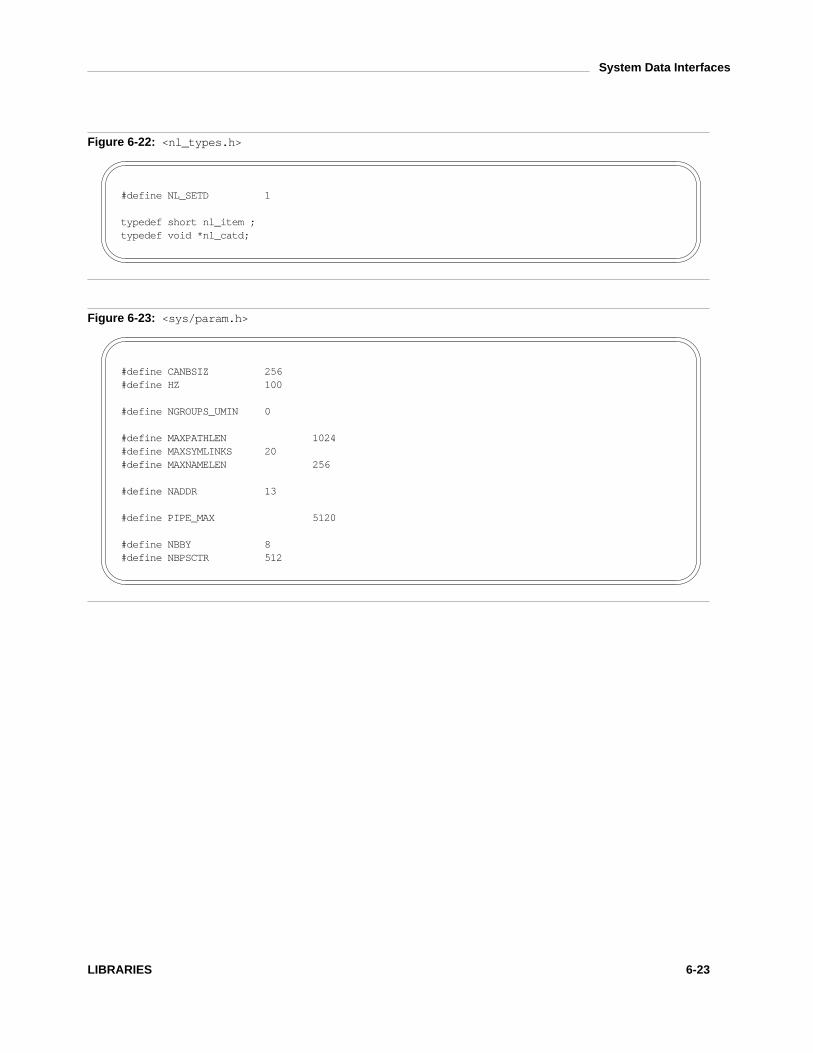
System Data Interfaces
Figure 6-22: < n l _ t y p e s . h >
# d e f i n e N L _ S E T D 1
t y p e d e f s h o r t n l _ i t e m ;t y p e d e f v o i d * n l _ c a t d ;
Figure 6-23: < s y s / p a r a m . h >
# d e f i n e C A N B S I Z 2 5 6# d e f i n e H Z 1 0 0
# d e f i n e N G R O U P S _ U M I N 0
# d e f i n e M A X P A T H L E N 1 0 2 4# d e f i n e M A X S Y M L I N K S 2 0# d e f i n e M A X N A M E L E N 2 5 6
# d e f i n e N A D D R 1 3
# d e f i n e P I P E _ M A X 5 1 2 0
# d e f i n e N B B Y 8# d e f i n e N B P S C T R 5 1 2
LIBRARIES 6-23

System Data Interfaces
Figure 6-24: < p o l l . h >
s t r u c t p o l l f d {i n t f d ;s h o r t e v e n t s ;s h o r t r e v e n t s ;
} ;
# d e f i n e P O L L I N 0 x 0 0 0 1# d e f i n e P O L L P R I 0 x 0 0 0 2# d e f i n e P O L L O U T 0 x 0 0 0 4# d e f i n e P O L L R D N O R M 0 x 0 0 4 0# d e f i n e P O L L W R N O R M P O L L O U T# d e f i n e P O L L R D B A N D 0 x 0 0 8 0# d e f i n e P O L L W R B A N D 0 x 0 1 0 0# d e f i n e P O L L N O R M P O L L R D N O R M
# d e f i n e P O L L E R R 0 x 0 0 0 8# d e f i n e P O L L H U P 0 x 0 0 1 0# d e f i n e P O L L N V A L 0 x 0 0 2 0
6-24 SPARC PROCESSOR SUPPLEMENT

System Data Interfaces
Figure 6-25: < s y s / p r o c s e t . h >
# d e f i n e P _ I N I T P I D 1# d e f i n e P _ I N I T U I D 0# d e f i n e P _ I N I T P G I D 0
t y p e d e f l o n g i d _ t ;
t y p e d e f e n u m i d t y p e {P _ P I D ,P _ P P I D ,P _ P G I D ,P _ S I D ,P _ C I D ,P _ U I D ,P _ G I D ,P _ A L L
} i d t y p e _ t ;
t y p e d e f e n u m i d o p {P O P _ D I F F ,P O P _ A N D ,P O P _ O R ,P O P _ X O R
} i d o p _ t ;
t y p e d e f s t r u c t p r o c s e t {i d o p _ t p _ o p ;i d t y p e _ t p _ l i d t y p e ;i d _ t p _ l i d ;i d t y p e _ t p _ r i d t y p e ;i d _ t p _ r i d ;
} p r o c s e t _ t ;
# d e f i n e P _ M Y I D ( - 1 )
LIBRARIES 6-25

System Data Interfaces
Figure 6-26: < p w d . h >
s t r u c t p a s s w d {c h a r * p w _ n a m e ;c h a r * p w _ p a s s w d ;u i d _ t p w _ u i d ;g i d _ t p w _ g i d ;c h a r * p w _ a g e ;c h a r * p w _ c o m m e n t ;c h a r * p w _ g e c o s ;c h a r * p w _ d i r ;c h a r * p w _ s h e l l ;
} ;
Figure 6-27: < s y s / r e s o u r c e . h >
# d e f i n e R L I M I T _ C P U 0# d e f i n e R L I M I T _ F S I Z E 1# d e f i n e R L I M I T _ D A T A 2# d e f i n e R L I M I T _ S T A C K 3# d e f i n e R L I M I T _ C O R E 4# d e f i n e R L I M I T _ N O F I L E 5# d e f i n e R L I M I T _ V M E M 6# d e f i n e R L I M I T _ A S R L I M I T _ V M E M# d e f i n e R L I M _ I N F I N I T Y 0 x 7 f f f f f f f
t y p e d e f u n s i g n e d l o n g r l i m _ t ;
s t r u c t r l i m i t {r l i m _ t r l i m _ c u r ;r l i m _ t r l i m _ m a x ;
} ;
6-26 SPARC PROCESSOR SUPPLEMENT

System Data Interfaces
Figure 6-28: < r p c . h >
# d e f i n e M A X _ A U T H _ B Y T E S 4 0 0# d e f i n e M A X N E T N A M E L E N 2 5 5# d e f i n e H E X K E Y B Y T E S 4 8
e n u m a u t h _ s t a t {A U T H _ O K = 0 ,A U T H _ B A D C R E D = 1 ,A U T H _ R E J E C T E D C R E D = 2 ,A U T H _ B A D V E R F = 3 ,A U T H _ R E J E C T E D V E R F = 4 ,A U T H _ T O O W E A K = 5 ,A U T H _ I N V A L I D R E S P = 6 ,A U T H _ F A I L E D = 7
} ;
u n i o n d e s _ b l o c k {s t r u c t {u n s i g n e d l o n g h i g h ;u n s i g n e d l o n g l o w ;
} k e y ;c h a r c [ 8 ] ;
} ;s t r u c t o p a q u e _ a u t h {i n t o a _ f l a v o r ;c h a r * o a _ b a s e ;u n s i g n e d i n t o a _ l e n g t h ;
} ;
t y p e d e f s t r u c t {s t r u c t o p a q u e _ a u t h a h _ c r e d ;s t r u c t o p a q u e _ a u t h a h _ v e r f ;u n i o n d e s _ b l o c k a h _ k e y ;s t r u c t a u t h _ o p s {v o i d ( * a h _ n e x t v e r f ) ( ) ;i n t ( * a h _ m a r s h a l ) ( ) ;i n t ( * a h _ v a l i d a t e ) ( ) ;i n t ( * a h _ r e f r e s h ) ( ) ;v o i d ( * a h _ d e s t r o y ) ( ) ;
} * a h _ o p s ;c h a r * a h _ p r i v a t e ;
} A U T H ;
(continued on next page )
LIBRARIES 6-27

System Data Interfaces
Figure 6-28: < r p c . h > (continued )
s t r u c t a u t h s y s _ p a r m s {u n s i g n e d l o n g a u p _ t i m e ;c h a r * a u p _ m a c h n a m e ;u i d _ t a u p _ u i d ;g i d _ t a u p _ g i d ;u n s i g n e d i n t a u p _ l e n ;g i d _ t * a u p _ g i d s ;
} ;e x t e r n s t r u c t o p a q u e _ a u t h _ n u l l _ a u t h ;
# d e f i n e A U T H _ N O N E 0# d e f i n e A U T H _ N U L L 0# d e f i n e A U T H _ S Y S 1# d e f i n e A U T H _ U N I X A U T H _ S Y S# d e f i n e A U T H _ S H O R T 2# d e f i n e A U T H _ D E S 3
e n u m c l n t _ s t a t {R P C _ S U C C E S S = 0 ,R P C _ C A N T E N C O D E A R G S = 1 ,R P C _ C A N T D E C O D E R E S = 2 ,R P C _ C A N T S E N D = 3 ,R P C _ C A N T R E C V = 4 ,R P C _ T I M E D O U T = 5 ,R P C _ I N T R = 1 8 ,R P C _ U D E R R O R = 2 3 ,R P C _ V E R S M I S M A T C H = 6 ,R P C _ A U T H E R R O R = 7 ,R P C _ P R O G U N A V A I L = 8 ,R P C _ P R O G V E R S M I S M A T C H = 9 ,R P C _ P R O C U N A V A I L = 1 0 ,R P C _ C A N T D E C O D E A R G S = 1 1 ,R P C _ S Y S T E M E R R O R = 1 2 ,R P C _ U N K N O W N H O S T = 1 3 ,R P C _ U N K N O W N P R O T O = 1 7 ,R P C _ U N K N O W N A D D R = 1 9 ,R P C _ N O B R O A D C A S T = 2 1 ,R P C _ R P C B F A I L U R E = 1 4 ,R P C _ P R O G N O T R E G I S T E R E D = 1 5 ,R P C _ N 2 A X L A T E F A I L U R E = 2 2 ,R P C _ T L I E R R O R = 2 0 ,R P C _ F A I L E D = 1 6
} ;
(continued on next page )
6-28 SPARC PROCESSOR SUPPLEMENT

System Data Interfaces
Figure 6-28: < r p c . h > (continued )
# d e f i n e R P C _ P M A P F A I L U R E R P C _ R P C B F A I L U R E# d e f i n e R P C _ A N Y S O C K - 1# d e f i n e R P C _ A N Y F D R P C _ A N Y S O C K
s t r u c t r p c _ e r r {e n u m c l n t _ s t a t r e _ s t a t u s ;u n i o n {
s t r u c t {i n t e r r n o ;i n t t _ e r r n o ;
} R E _ e r r ;e n u m a u t h _ s t a t R E _ w h y ;s t r u c t {u n s i g n e d l o n g l o w ;u n s i g n e d l o n g h i g h ;
} R E _ v e r s ;s t r u c t {l o n g s 1 ;l o n g s 2 ;
} R E _ l b ;} r u ;
} ;
s t r u c t r p c _ c r e a t e e r r {e n u m c l n t _ s t a t c f _ s t a t ;s t r u c t r p c _ e r r c f _ e r r o r ;
} ;
t y p e d e f s t r u c t {A U T H * c l _ a u t h ;s t r u c t c l n t _ o p s {e n u m c l n t _ s t a t ( * c l _ c a l l ) ( ) ;v o i d ( * c l _ a b o r t ) ( ) ;v o i d ( * c l _ g e t e r r ) ( ) ;i n t ( * c l _ f r e e r e s ) ( ) ;v o i d ( * c l _ d e s t r o y ) ( ) ;i n t ( * c l _ c o n t r o l ) ( ) ;
} * c l _ o p s ;c h a r * c l _ p r i v a t e ;c h a r * c l _ n e t i d ;c h a r * c l _ t p ;
} C L I E N T ;
# d e f i n e F E E D B A C K _ R E X M I T 1 1# d e f i n e F E E D B A C K _ O K 2
# d e f i n e C L S E T _ T I M E O U T 1# d e f i n e C L G E T _ T I M E O U T 2# d e f i n e C L G E T _ S E R V E R _ A D D R 3# d e f i n e C L G E T _ F D 6# d e f i n e C L G E T _ S V C _ A D D R 7# d e f i n e C L S E T _ F D _ C L O S E 8# d e f i n e C L S E T _ F D _ N C L O S E 9
(continued on next page )
LIBRARIES 6-29
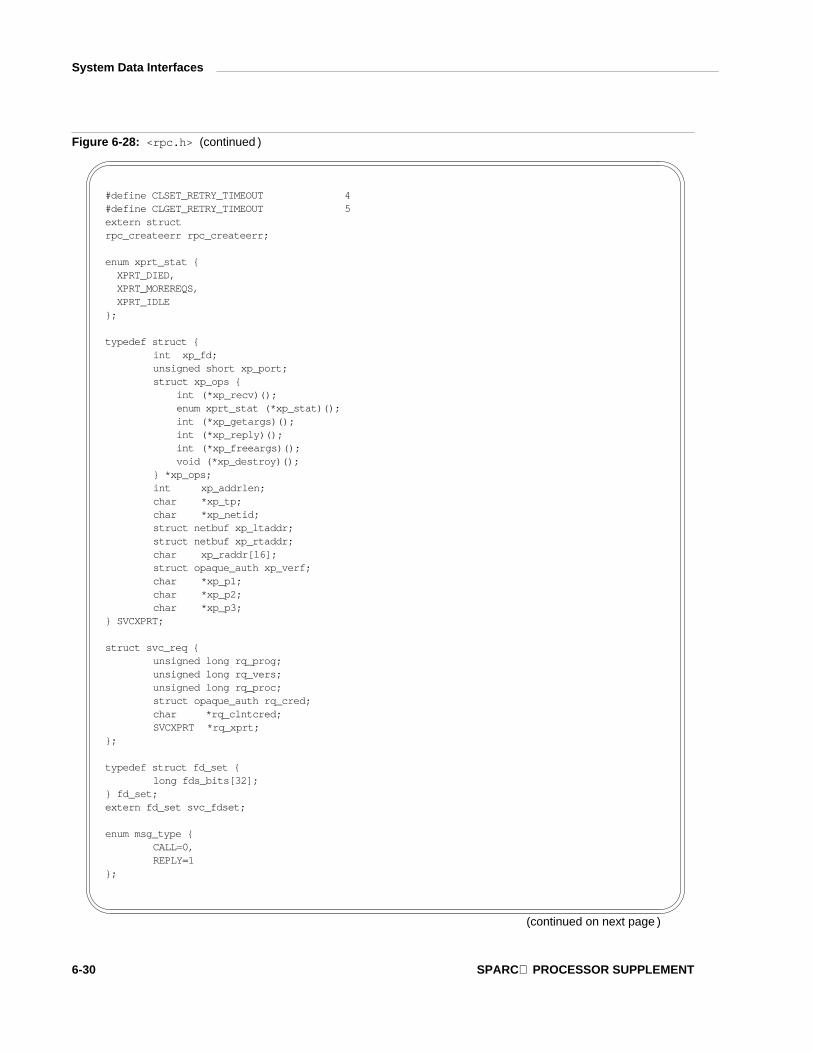
System Data Interfaces
Figure 6-28: < r p c . h > (continued )
# d e f i n e C L S E T _ R E T R Y _ T I M E O U T 4# d e f i n e C L G E T _ R E T R Y _ T I M E O U T 5e x t e r n s t r u c tr p c _ c r e a t e e r r r p c _ c r e a t e e r r ;
e n u m x p r t _ s t a t {X P R T _ D I E D ,X P R T _ M O R E R E Q S ,X P R T _ I D L E
} ;
t y p e d e f s t r u c t {i n t x p _ f d ;u n s i g n e d s h o r t x p _ p o r t ;s t r u c t x p _ o p s {
i n t ( * x p _ r e c v ) ( ) ;e n u m x p r t _ s t a t ( * x p _ s t a t ) ( ) ;i n t ( * x p _ g e t a r g s ) ( ) ;i n t ( * x p _ r e p l y ) ( ) ;i n t ( * x p _ f r e e a r g s ) ( ) ;v o i d ( * x p _ d e s t r o y ) ( ) ;
} * x p _ o p s ;i n t x p _ a d d r l e n ;c h a r * x p _ t p ;c h a r * x p _ n e t i d ;s t r u c t n e t b u f x p _ l t a d d r ;s t r u c t n e t b u f x p _ r t a d d r ;c h a r x p _ r a d d r [ 1 6 ] ;s t r u c t o p a q u e _ a u t h x p _ v e r f ;c h a r * x p _ p 1 ;c h a r * x p _ p 2 ;c h a r * x p _ p 3 ;
} S V C X P R T ;
s t r u c t s v c _ r e q {u n s i g n e d l o n g r q _ p r o g ;u n s i g n e d l o n g r q _ v e r s ;u n s i g n e d l o n g r q _ p r o c ;s t r u c t o p a q u e _ a u t h r q _ c r e d ;c h a r * r q _ c l n t c r e d ;S V C X P R T * r q _ x p r t ;
} ;
t y p e d e f s t r u c t f d _ s e t {l o n g f d s _ b i t s [ 3 2 ] ;
} f d _ s e t ;e x t e r n f d _ s e t s v c _ f d s e t ;
e n u m m s g _ t y p e {C A L L = 0 ,R E P L Y = 1
} ;
(continued on next page )
6-30 SPARC PROCESSOR SUPPLEMENT

System Data Interfaces
Figure 6-28: < r p c . h > (continued )
e n u m r e p l y _ s t a t {M S G _ A C C E P T E D = 0 ,M S G _ D E N I E D = 1
} ;
e n u m a c c e p t _ s t a t {S U C C E S S = 0 ,P R O G _ U N A V A I L = 1 ,P R O G _ M I S M A T C H = 2 ,P R O C _ U N A V A I L = 3 ,G A R B A G E _ A R G S = 4 ,S Y S T E M _ E R R = 5
} ;
e n u m r e j e c t _ s t a t {R P C _ M I S M A T C H = 0 ,A U T H _ E R R O R = 1
} ;
s t r u c t a c c e p t e d _ r e p l y {s t r u c t o p a q u e _ a u t h a r _ v e r f ;e n u m a c c e p t _ s t a t a r _ s t a t ;u n i o n {s t r u c t {u n s i g n e d l o n g l o w ;u n s i g n e d l o n g h i g h ;} A R _ v e r s i o n s ;s t r u c t {c h a r * w h e r e ;x d r p r o c _ t p r o c ;} A R _ r e s u l t s ;} r u ;
} ;
s t r u c t r e j e c t e d _ r e p l y {e n u m r e j e c t _ s t a t r j _ s t a t ;u n i o n {s t r u c t {u n s i g n e d l o n g l o w ;u n s i g n e d l o n g h i g h ;} R J _ v e r s i o n s ;e n u m a u t h _ s t a t R J _ w h y ;} r u ;
} ;
s t r u c t r e p l y _ b o d y {e n u m r e p l y _ s t a t r p _ s t a t ;u n i o n {s t r u c t a c c e p t e d _ r e p l y R P _ a r ;s t r u c t r e j e c t e d _ r e p l y R P _ d r ;
} r u ;} ;
(continued on next page )
LIBRARIES 6-31

System Data Interfaces
Figure 6-28: < r p c . h > (continued )
s t r u c t c a l l _ b o d y {u n s i g n e d l o n g c b _ r p c v e r s ;u n s i g n e d l o n g c b _ p r o g ;u n s i g n e d l o n g c b _ v e r s ;u n s i g n e d l o n g c b _ p r o c ;s t r u c t o p a q u e _ a u t h c b _ c r e d ;s t r u c t o p a q u e _ a u t h c b _ v e r f ;
} ;
s t r u c t r p c _ m s g {u n s i g n e d l o n g r m _ x i d ;e n u m m s g _ t y p e r m _ d i r e c t i o n ;u n i o n {s t r u c t c a l l _ b o d y R M _ c m b ;s t r u c t r e p l y _ b o d y R M _ r m b ;
} r u ;} ;
s t r u c t r p c b {u n s i g n e d l o n g r _ p r o g ;u n s i g n e d l o n g r _ v e r s ;c h a r * r _ n e t i d ;c h a r * r _ a d d r ;c h a r * r _ o w n e r ;
} ;
s t r u c t r p c b l i s t {s t r u c t r p c b r p c b _ m a p ;s t r u c t r p c b l i s t * r p c b _ n e x t ;
} ;
e n u m x d r _ o p {X D R _ E N C O D E = 0 ,X D R _ D E C O D E = 1 ,X D R _ F R E E = 2
} ;
s t r u c t x d r _ d i s c r i m {i n t v a l u e ;x d r p r o c _ t p r o c ;
} ;
e n u m a u t h d e s _ n a m e k i n d {A D N _ F U L L N A M E ,A D N _ N I C K N A M E
} ;
s t r u c t a u t h d e s _ f u l l n a m e {c h a r * n a m e ;u n i o n d e s _ b l o c k k e y ;u n s i g n e d l o n g w i n d o w ;
} ;
(continued on next page )
6-32 SPARC PROCESSOR SUPPLEMENT

System Data Interfaces
Figure 6-28: < r p c . h > (continued )
s t r u c t a u t h d e s _ c r e d {e n u m a u t h d e s _ n a m e k i n d a d c _ n a m e k i n d ;s t r u c t a u t h d e s _ f u l l n a m e a d c _ f u l l n a m e ;u n s i g n e d l o n g a d c _ n i c k n a m e ;
} ;t y p e d e f s t r u c t {
e n u m x d r _ o p x _ o p ;s t r u c t x d r _ o p s {i n t ( * x _ g e t l o n g ) ( ) ;i n t ( * x _ p u t l o n g ) ( ) ;i n t ( * x _ g e t b y t e s ) ( ) ;i n t ( * x _ p u t b y t e s ) ( ) ;u n s i g n e d i n t ( * x _ g e t p o s t n ) ( ) ;i n t ( * x _ s e t p o s t n ) ( ) ;l o n g * ( * x _ i n l i n e ) ( ) ;v o i d ( * x _ d e s t r o y ) ( ) ;
} * x _ o p s ;c h a r * x _ p u b l i c ;c h a r * x _ p r i v a t e ;c h a r * x _ b a s e ;i n t x _ h a n d y ;
} X D R ;
t y p e d e f i n t ( * x d r p r o c _ t ) ( )# d e f i n e N U L L _ x d r p r o c _ t ( ( x d r p r o c _ t ) 0 )# d e f i n e a u t h _ d e s t r o y ( a u t h ) \
( ( * ( ( a u t h ) - > a h _ o p s - > a h _ d e s t r o y ) ) ( a u t h ) )# d e f i n e c l n t _ c a l l ( r h , p r o c , x a r g s , a r g s p , x r e s , r e s p , s e c s ) \
( ( * ( r h ) - > c l _ o p s - > c l _ c a l l ) ( r h , p r o c , x a r g s , a r g s p , x r e s , r e s p , s e c s ) )# d e f i n e c l n t _ f r e e r e s ( r h , x r e s , r e s p ) \
( ( * ( r h ) - > c l _ o p s - > c l _ f r e e r e s ) ( r h , x r e s , r e s p ) )# d e f i n e c l n t _ g e t e r r ( r h , e r r p ) \
( ( * ( r h ) - > c l _ o p s - > c l _ g e t e r r ) ( r h , e r r p ) )# d e f i n e c l n t _ c o n t r o l ( c l , r q , i n ) \
( ( * ( c l ) - > c l _ o p s - > c l _ c o n t r o l ) ( c l , r q , i n ) )# d e f i n e c l n t _ d e s t r o y ( r h ) \
( ( * ( r h ) - > c l _ o p s - > c l _ d e s t r o y ) ( r h ) )# d e f i n e s v c _ d e s t r o y ( x p r t ) \
( * ( x p r t ) - > x p _ o p s - > x p _ d e s t r o y ) ( x p r t )# d e f i n e s v c _ f r e e a r g s ( x p r t , x a r g s , a r g s p ) \
( * ( x p r t ) - > x p _ o p s - > x p _ f r e e a r g s ) ( ( x p r t ) , ( x a r g s ) , ( a r g s p ) )# d e f i n e s v c _ g e t a r g s ( x p r t , x a r g s , a r g s p ) \
( * ( x p r t ) - > x p _ o p s - > x p _ g e t a r g s ) ( ( x p r t ) , ( x a r g s ) , ( a r g s p ) )# d e f i n e s v c _ g e t r p c c a l l e r ( x ) \
( & ( x ) - > x p _ r t a d d r )# d e f i n e x d r _ g e t p o s ( x d r s ) \
( * ( x d r s ) - > x _ o p s - > x _ g e t p o s t n ) ( x d r s )# d e f i n e x d r _ s e t p o s ( x d r s , p o s ) \
( * ( x d r s ) - > x _ o p s - > x _ s e t p o s t n ) ( x d r s , p o s )# d e f i n e x d r _ i n l i n e ( x d r s , l e n ) \
( * ( x d r s ) - > x _ o p s - > x _ i n l i n e ) ( x d r s , l e n )# d e f i n e x d r _ d e s t r o y ( x d r s ) \
( * ( x d r s ) - > x _ o p s - > x _ d e s t r o y ) ( x d r s )
(continued on next page )
LIBRARIES 6-33
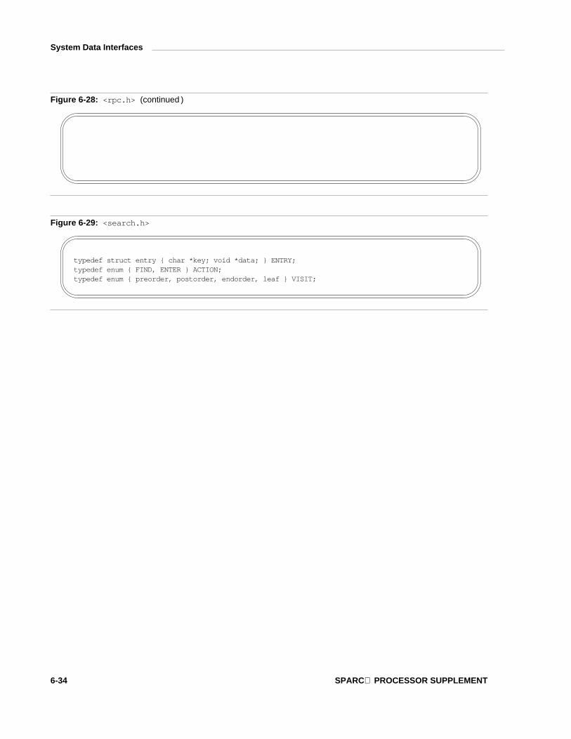
System Data Interfaces
Figure 6-28: < r p c . h > (continued )
Figure 6-29: < s e a r c h . h >
t y p e d e f s t r u c t e n t r y { c h a r * k e y ; v o i d * d a t a ; } E N T R Y ;t y p e d e f e n u m { F I N D , E N T E R } A C T I O N ;t y p e d e f e n u m { p r e o r d e r , p o s t o r d e r , e n d o r d e r , l e a f } V I S I T ;
6-34 SPARC PROCESSOR SUPPLEMENT

System Data Interfaces
Figure 6-30: < s y s / s e m . h >
# d e f i n e S E M _ U N D O 0 1 0 0 0 0
# d e f i n e G E T N C N T 3# d e f i n e G E T P I D 4# d e f i n e G E T V A L 5# d e f i n e G E T A L L 6# d e f i n e G E T Z C N T 7# d e f i n e S E T V A L 8# d e f i n e S E T A L L 9
s t r u c t s e m i d _ d s {s t r u c t i p c _ p e r m s e m _ p e r m ;s t r u c t s e m * s e m _ b a s e ;u n s i g n e d s h o r t s e m _ n s e m s ;t i m e _ t s e m _ o t i m e ;l o n g s e m _ p a d 1 ;t i m e _ t s e m _ c t i m e ;l o n g s e m _ p a d 2 ;l o n g s e m _ p a d 3 [ 4 ] ;
} ;
s t r u c t s e m {u n s i g n e d s h o r t s e m v a l ;p i d _ t s e m p i d ;u n s i g n e d s h o r t s e m n c n t ;u n s i g n e d s h o r t s e m z c n t ;
} ;
s t r u c t s e m b u f {u n s i g n e d s h o r t s e m _ n u m ;s h o r t s e m _ o p ;s h o r t s e m _ f l g ;
} ;
Figure 6-31: < s e t j m p . h >
# d e f i n e _ J B L E N 1 2# d e f i n e _ S I G J B L E N 1 9t y p e d e f i n t j m p _ b u f [ _ J B L E N ] ;t y p e d e f i n t s i g j m p _ b u f [ _ S I G J B L E N ] ;
LIBRARIES 6-35

System Data Interfaces
Figure 6-32: < s y s / s h m . h >
s t r u c t s h m i d _ d s {s t r u c t i p c _ p e r m s h m _ p e r m ;i n t s h m _ s e g s z ;s t r u c t a n o n _ m a p * s h m _ a m p ;u n s i g n e d s h o r t s h m _ l k c n t ;p i d _ t s h m _ l p i d ;p i d _ t s h m _ c p i d ;u n s i g n e d l o n g s h m _ n a t t c h ;u n s i g n e d l o n g s h m _ c n a t t c h ;t i m e _ t s h m _ a t i m e ;l o n g s h m _ p a d 1 ;t i m e _ t s h m _ d t i m e ;l o n g s h m _ p a d 2 ;t i m e _ t s h m _ c t i m e ;l o n g s h m _ p a d 3 ;l o n g s h m _ p a d 4 [ 4 ] ;
} ;
# d e f i n e S H M _ R D O N L Y 0 1 0 0 0 0# d e f i n e S H M _ R N D 0 2 0 0 0 0
Figure 6-33: < s i g n a l . h >
# d e f i n e S I G H U P 1# d e f i n e S I G I N T 2# d e f i n e S I G Q U I T 3# d e f i n e S I G I L L 4# d e f i n e S I G T R A P 5# d e f i n e S I G A B R T 6# d e f i n e S I G E M T 7# d e f i n e S I G F P E 8# d e f i n e S I G K I L L 9# d e f i n e S I G B U S 1 0# d e f i n e S I G S E G V 1 1# d e f i n e S I G S Y S 1 2# d e f i n e S I G P I P E 1 3# d e f i n e S I G A L R M 1 4# d e f i n e S I G T E R M 1 5# d e f i n e S I G U S R 1 1 6# d e f i n e S I G U S R 2 1 7# d e f i n e S I G C H L D 1 8# d e f i n e S I G P W R 1 9# d e f i n e S I G W I N C H 2 0# d e f i n e S I G U R G 2 1# d e f i n e S I G P O L L 2 2# d e f i n e S I G S T O P 2 3
(continued on next page )
6-36 SPARC PROCESSOR SUPPLEMENT

System Data Interfaces
Figure 6-33: < s i g n a l . h > (continued )
# d e f i n e S I G T S T P 2 4# d e f i n e S I G C O N T 2 5# d e f i n e S I G T T I N 2 6# d e f i n e S I G T T O U 2 7# d e f i n e S I G X C P U 3 0# d e f i n e S I G X F S Z 3 1# d e f i n e S I G _ B L O C K 1# d e f i n e S I G _ U N B L O C K 2# d e f i n e S I G _ S E T M A S K 3# d e f i n e S I G _ E R R ( v o i d ( * ) ( ) ) - 1# d e f i n e S I G _ I G N ( v o i d ( * ) ( ) ) 1# d e f i n e S I G _ H O L D ( v o i d ( * ) ( ) ) 2# d e f i n e S I G _ D F L ( v o i d ( * ) ( ) ) 0
# d e f i n e S S _ O N S T A C K 0 x 0 0 0 0 0 0 0 1# d e f i n e S S _ D I S A B L E 0 x 0 0 0 0 0 0 0 2
s t r u c t s i g a l t s t a c k {c h a r * s s _ s p ;i n t s s _ s i z e ;i n t s s _ f l a g s ;
} ;t y p e d e f s t r u c t s i g a l t s t a c k s t a c k _ t ;t y p e d e f s t r u c t { u n s i g n e d l o n g s i g b i t s [ 4 ] ; } s i g s e t _ t ;s t r u c t s i g a c t i o n {
i n t s a _ f l a g s ;s i g d i s p _ t s a _ d i s p ;s i g s e t _ t s a _ m a s k ;i n t s a _ r e s v [ 2 ] ;
} ;
# d e f i n e S A _ O N S T A C K 0 x 0 0 0 0 0 0 0 1# d e f i n e S A _ R E S E T H A N D 0 x 0 0 0 0 0 0 0 2# d e f i n e S A _ R E S T A R T 0 x 0 0 0 0 0 0 0 4# d e f i n e S A _ S I G I N F O 0 x 0 0 0 0 0 0 0 8# d e f i n e S A _ N O C L D W A I T 0 x 0 0 0 1 0 0 0 0# d e f i n e S A _ N O C L D S T O P 0 x 0 0 0 2 0 0 0 0
LIBRARIES 6-37

System Data Interfaces
Figure 6-34: < s y s / s i g i n f o . h >
# d e f i n e I L L _ I L L O P C 1# d e f i n e I L L _ I L L O P N 2# d e f i n e I L L _ I L L A D R 3# d e f i n e I L L _ I L L T R P 4# d e f i n e I L L _ P R V O P C 5# d e f i n e I L L _ P R V R E G 6# d e f i n e I L L _ C O P R O C 7# d e f i n e I L L _ B A D S T K 8# d e f i n e F P E _ I N T D I V 1# d e f i n e F P E _ I N T O V F 2# d e f i n e F P E _ F L T D I V 3# d e f i n e F P E _ F L T O V F 4# d e f i n e F P E _ F L T U N D 5# d e f i n e F P E _ F L T R E S 6# d e f i n e F P E _ F L T I N V 7# d e f i n e F P E _ F L T S U B 8# d e f i n e S E G V _ M A P E R R 1# d e f i n e S E G V _ A C C E R R 2# d e f i n e B U S _ A D R A L N 1# d e f i n e B U S _ A D R E R R 2# d e f i n e B U S _ O B J E R R 3# d e f i n e T R A P _ B R K P T 1# d e f i n e T R A P _ T R A C E 2# d e f i n e C L D _ E X I T E D 1# d e f i n e C L D _ K I L L E D 2# d e f i n e C L D _ D U M P E D 3# d e f i n e C L D _ T R A P P E D 4# d e f i n e C L D _ S T O P P E D 5# d e f i n e C L D _ C O N T I N U E D 6# d e f i n e P O L L _ I N 1# d e f i n e P O L L _ O U T 2# d e f i n e P O L L _ M S G 3# d e f i n e P O L L _ E R R 4# d e f i n e P O L L _ P R I 5# d e f i n e P O L L _ H U P 6# d e f i n e S I _ M A X S Z 1 2 8# d e f i n e S I _ P A D ( ( S I _ M A X S Z / s i z e o f ( i n t ) ) - 3 )
t y p e d e f s t r u c t s i g i n f o {i n t s i _ s i g n o ;i n t s i _ c o d e ;i n t s i _ e r r n o ;u n i o n {i n t _ p a d [ S I _ P A D ] ;s t r u c t {
p i d _ t _ p i d ;u n i o n {s t r u c t { u i d _ t _ u i d ; } _ k i l l ;s t r u c t {
c l o c k _ t _ u t i m e ;i n t _ s t a t u s ;c l o c k _ t _ s t i m e ;
} _ c l d ;
(continued on next page )
6-38 SPARC PROCESSOR SUPPLEMENT

System Data Interfaces
Figure 6-34: < s y s / s i g i n f o . h > (continued )
} _ p d a t a ;} _ p r o c ;s t r u c t { c h a r * _ a d d r ; } _ f a u l t ;s t r u c t {
i n t _ f d ;l o n g _ b a n d ;
} _ f i l e ;} _ d a t a ;
} s i g i n f o _ t ;
# d e f i n e s i _ p i d _ d a t a . _ p r o c . _ p i d# d e f i n e s i _ u i d _ d a t a . _ p r o c . _ p d a t a . _ k i l l . _ u i d# d e f i n e s i _ a d d r _ d a t a . _ f a u l t . _ a d d r# d e f i n e s i _ s t a t u s _ d a t a . _ p r o c . _ p d a t a . _ c l d . _ s t a t u s# d e f i n e s i _ b a n d _ d a t a . _ f i l e . _ b a n d
Figure 6-35: < s y s / s t a t . h >
# d e f i n e _ S T _ F S T Y P S Z 1 6
s t r u c t s t a t {d e v _ t s t _ d e v ;l o n g s t _ p a d 1 [ 3 ] ;i n o _ t s t _ i n o ;m o d e _ t s t _ m o d e ;n l i n k _ t s t _ n l i n k ;u i d _ t s t _ u i d ;g i d _ t s t _ g i d ;d e v _ t s t _ r d e v ;l o n g s t _ p a d 2 [ 2 ] ;o f f _ t s t _ s i z e ;l o n g s t _ p a d 3 ;t i m e s t r u c _ t s t _ a t i m ;t i m e s t r u c _ t s t _ m t i m ;t i m e s t r u c _ t s t _ c t i m ;l o n g s t _ b l k s i z e ;l o n g s t _ b l o c k s ;c h a r s t _ f s t y p e [ _ S T _ F S T Y P S Z ] ;l o n g s t _ p a d 4 [ 8 ] ;
} ;
# d e f i n e s t _ a t i m e s t _ a t i m . t v _ s e c# d e f i n e s t _ m t i m e s t _ m t i m . t v _ s e c# d e f i n e s t _ c t i m e s t _ c t i m . t v _ s e c# d e f i n e S _ I F M T 0 x F 0 0 0# d e f i n e S _ I F I F O 0 x 1 0 0 0
(continued on next page )
LIBRARIES 6-39

System Data Interfaces
Figure 6-35: < s y s / s t a t . h > (continued )
# d e f i n e S _ I F C H R 0 x 2 0 0 0# d e f i n e S _ I F D I R 0 x 4 0 0 0# d e f i n e S _ I F B L K 0 x 6 0 0 0# d e f i n e S _ I F R E G 0 x 8 0 0 0# d e f i n e S _ I F L N K 0 x A 0 0 0# d e f i n e S _ I S U I D 0 4 0 0 0# d e f i n e S _ I S G I D 0 2 0 0 0# d e f i n e S _ I S V T X 0 1 0 0 0# d e f i n e S _ I R W X U 0 0 7 0 0# d e f i n e S _ I R U S R 0 0 4 0 0# d e f i n e S _ I W U S R 0 0 2 0 0# d e f i n e S _ I X U S R 0 0 1 0 0# d e f i n e S _ I R W X G 0 0 0 7 0# d e f i n e S _ I R G R P 0 0 0 4 0# d e f i n e S _ I W G R P 0 0 0 2 0# d e f i n e S _ I X G R P 0 0 0 1 0# d e f i n e S _ I R W X O 0 0 0 0 7# d e f i n e S _ I R O T H 0 0 0 0 4# d e f i n e S _ I W O T H 0 0 0 0 2# d e f i n e S _ I X O T H 0 0 0 0 1
# d e f i n e S _ I S F I F O ( m o d e ) ( ( m o d e & S _ I F M T ) = = S _ I F I F O )# d e f i n e S _ I S C H R ( m o d e ) ( ( m o d e & S _ I F M T ) = = S _ I F C H R )# d e f i n e S _ I S D I R ( m o d e ) ( ( m o d e & S _ I F M T ) = = S _ I F D I R )# d e f i n e S _ I S B L K ( m o d e ) ( ( m o d e & S _ I F M T ) = = S _ I F B L K )# d e f i n e S _ I S R E G ( m o d e ) ( ( m o d e & S _ I F M T ) = = S _ I F R E G )
6-40 SPARC PROCESSOR SUPPLEMENT

System Data Interfaces
Figure 6-36: < s y s / s t a t v f s . h >
# d e f i n e F S T Y P S Z 1 6
t y p e d e f s t r u c t s t a t v f s {u n s i g n e d l o n g f _ b s i z e ;u n s i g n e d l o n g f _ f r s i z e ;u n s i g n e d l o n g f _ b l o c k s ;u n s i g n e d l o n g f _ b f r e e ;u n s i g n e d l o n g f _ b a v a i l ;u n s i g n e d l o n g f _ f i l e s ;u n s i g n e d l o n g f _ f f r e e ;u n s i g n e d l o n g f _ f a v a i l ;u n s i g n e d l o n g f _ f s i d ;c h a r f _ b a s e t y p e [ F S T Y P S Z ] ;u n s i g n e d l o n g f _ f l a g ;u n s i g n e d l o n g f _ n a m e m a x ;c h a r f _ f s t r [ 3 2 ] ;u n s i g n e d l o n g f _ f i l l e r [ 1 6 ] ;
} s t a t v f s _ t ;
# d e f i n e S T _ R D O N L Y 0 x 0 1# d e f i n e S T _ N O S U I D 0 x 0 2
Figure 6-37: < s t d a r g . h >
# d e f i n e _ V A _ L I S T v o i d *
t y p e d e f _ V A _ L I S T v a _ l i s t ;
# d e f i n e v a _ s t a r t ( l i s t , n a m e ) ( v o i d ) ( l i s t = ( v a _ l i s t ) & _ _ b u i l t i n _ v a _ a l i s t )# d e f i n e v a _ a r g ( l i s t , m o d e ) ( ( m o d e * ) _ _ b u i l t i n _ v a _ a r g _ i n c r ( ( m o d e * ) l i s t ) ) [ 0 ]
e x t e r n v o i d v a _ e n d ( v a _ l i s t ) ;
# d e f i n e v a _ e n d ( l i s t ) ( v o i d ) 0
LIBRARIES 6-41

System Data Interfaces
Figure 6-38: < s t d d e f . h >
# d e f i n e N U L L 0t y p e d e f i n t p t r d i f f _ t ;t y p e d e f u n s i g n e d i n t s i z e _ t ;t y p e d e f l o n g w c h a r _ t ;
6-42 SPARC PROCESSOR SUPPLEMENT

System Data Interfaces
Figure 6-39: < s t d i o . h >
t y p e d e f u n s i g n e d i n t s i z e _ t ;t y p e d e f l o n g f p o s _ t ;
# d e f i n e N U L L 0# d e f i n e B U F S I Z 1 0 2 4# d e f i n e _ I O F B F 0 0 0 0# d e f i n e _ I O L B F 0 1 0 0# d e f i n e _ I O N B F 0 0 0 4# d e f i n e _ I O E O F 0 0 2 0# d e f i n e _ I O E R R 0 0 4 0# d e f i n e E O F ( - 1 )# d e f i n e F O P E N _ M A X 2 0# d e f i n e F I L E N A M E _ M A X 1 0 2 4
# d e f i n e s t d i n ( & _ _ i o b [ 0 ] )# d e f i n e s t d o u t ( & _ _ i o b [ 1 ] )# d e f i n e s t d e r r ( & _ _ i o b [ 2 ] )
# d e f i n e c l e a r e r r ( p ) ( ( v o i d ) ( ( p ) - > _ f l a g & = ̃ ( _ I O E R R | _ I O E O F ) ) ) †# d e f i n e f e o f ( p ) ( ( p ) - > _ f l a g & _ I O E O F )# d e f i n e f e r r o r ( p ) ( ( p ) - > _ f l a g & _ I O E R R )# d e f i n e f i l e n o ( p ) ( p ) - > _ f i l e †
# d e f i n e L _ c t e r m i d 9# d e f i n e L _ c u s e r i d 9# d e f i n e P _ t m p d i r " / v a r / t m p / "# d e f i n e L _ t m p n a m 2 5
t y p e d e f s t r u c t {i n t _ c n t ;u n s i g n e d c h a r * _ p t r ;u n s i g n e d c h a r * _ b a s e ;u n s i g n e d c h a r _ f l a g ;u n s i g n e d c h a r _ f i l e ;
} F I L E ;
e x t e r n F I L E _ _ i o b [ F O P E N _ M A X ] ;
† These macros definitions are moved to Level 2 in this release. †† The _file member of the FILE structis moved to Level 2 as of Jan. 1 1993.
NOTE
The macros clearerr, and fileno will be removed as a source interface in a future release support-ing multi-processing. This will have no effect on binary portability.
LIBRARIES 6-43

System Data Interfaces
CAUTION The constant _NFILE has been removed. It should still appear in stdio.h, but may be removed in afuture version of the header file. Applications may not be able to depend on fopen() failing on anattempt to open more than _NFILE files.
Figure 6-40: < s t d l i b . h >
t y p e d e f s t r u c t {i n t q u o t ;i n t r e m ;
} d i v _ t ;
t y p e d e f s t r u c t {l o n g q u o t ;l o n g r e m ;
} l d i v _ t ;
t y p e d e f u n s i g n e d i n t s i z e _ t ;
# d e f i n e N U L L 0# d e f i n e E X I T _ F A I L U R E 1# d e f i n e E X I T _ S U C C E S S 0# d e f i n e R A N D _ M A X 3 2 7 6 7
e x t e r n u n s i g n e d c h a r _ _ c t y p e [ ] ;# d e f i n e M B _ C U R _ M A X _ _ c t y p e [ 5 2 0 ]
Figure 6-41: < s t r o p t s . h >
# d e f i n e S N D Z E R O 0 x 0 0 1# d e f i n e R N O R M 0 x 0 0 0# d e f i n e R M S G D 0 x 0 0 1# d e f i n e R M S G N 0 x 0 0 2# d e f i n e R M O D E M A S K 0 x 0 0 3# d e f i n e R P R O T D A T 0 x 0 0 4# d e f i n e R P R O T D I S 0 x 0 0 8# d e f i n e R P R O T N O R M 0 x 0 1 0
# d e f i n e F L U S H R 0 x 0 1# d e f i n e F L U S H W 0 x 0 2# d e f i n e F L U S H R W 0 x 0 3
# d e f i n e S _ I N P U T 0 x 0 0 0 1# d e f i n e S _ H I P R I 0 x 0 0 0 2# d e f i n e S _ O U T P U T 0 x 0 0 0 4# d e f i n e S _ M S G 0 x 0 0 0 8# d e f i n e S _ E R R O R 0 x 0 0 1 0# d e f i n e S _ H A N G U P 0 x 0 0 2 0
(continued on next page )
6-44 SPARC PROCESSOR SUPPLEMENT

System Data Interfaces
Figure 6-41: < s t r o p t s . h > (continued )
# d e f i n e S _ R D N O R M 0 x 0 0 4 0# d e f i n e S _ W R N O R M S _ O U T P U T# d e f i n e S _ R D B A N D 0 x 0 0 8 0# d e f i n e S _ W R B A N D 0 x 0 1 0 0# d e f i n e S _ B A N D U R G 0 x 0 2 0 0
# d e f i n e R S _ H I P R I 1# d e f i n e M S G _ H I P R I 0 x 0 1# d e f i n e M S G _ A N Y 0 x 0 2# d e f i n e M S G _ B A N D 0 x 0 4
# d e f i n e M O R E C T L 1# d e f i n e M O R E D A T A 2
# d e f i n e M U X I D _ A L L ( - 1 )# d e f i n e S T R ( ’ S ’ < < 8 )# d e f i n e I _ N R E A D ( S T R | 0 1 )# d e f i n e I _ P U S H ( S T R | 0 2 )# d e f i n e I _ P O P ( S T R | 0 3 )# d e f i n e I _ L O O K ( S T R | 0 4 )# d e f i n e I _ F L U S H ( S T R | 0 5 )# d e f i n e I _ S R D O P T ( S T R | 0 6 )# d e f i n e I _ G R D O P T ( S T R | 0 7 )# d e f i n e I _ S T R ( S T R | 0 1 0 )# d e f i n e I _ S E T S I G ( S T R | 0 1 1 )# d e f i n e I _ G E T S I G ( S T R | 0 1 2 )# d e f i n e I _ F I N D ( S T R | 0 1 3 )# d e f i n e I _ L I N K ( S T R | 0 1 4 )# d e f i n e I _ U N L I N K ( S T R | 0 1 5 )# d e f i n e I _ P E E K ( S T R | 0 1 7 )# d e f i n e I _ F D I N S E R T ( S T R | 0 2 0 )# d e f i n e I _ S E N D F D ( S T R | 0 2 1 )# d e f i n e I _ R E C V F D ( S T R | 0 1 6 )# d e f i n e I _ S W R O P T ( S T R | 0 2 3 )# d e f i n e I _ G W R O P T ( S T R | 0 2 4 )# d e f i n e I _ L I S T ( S T R | 0 2 5 )# d e f i n e I _ P L I N K ( S T R | 0 2 6 )# d e f i n e I _ P U N L I N K ( S T R | 0 2 7 )# d e f i n e I _ F L U S H B A N D ( S T R | 0 3 4 )# d e f i n e I _ C K B A N D ( S T R | 0 3 5 )# d e f i n e I _ G E T B A N D ( S T R | 0 3 6 )# d e f i n e I _ A T M A R K ( S T R | 0 3 7 )# d e f i n e I _ S E T C L T I M E ( S T R | 0 4 0 )# d e f i n e I _ G E T C L T I M E ( S T R | 0 4 1 )# d e f i n e I _ C A N P U T ( S T R | 0 4 2 )
s t r u c t s t r i o c t l {i n t i c _ c m d ;i n t i c _ t i m o u t ;i n t i c _ l e c ;c h a r * i c _ d p ;
} ;
s t r u c t s t r b u f {i n t m a x l e n ;
(continued on next page )
LIBRARIES 6-45

System Data Interfaces
Figure 6-41: < s t r o p t s . h > (continued )
i n t l e n ;c h a r * b u f ;
} ;
s t r u c t s t r p e e k {s t r u c t s t r b u f c t l b u f ;s t r u c t s t r b u f d a t a b u f ;l o n g f l a g s ;
} ;
s t r u c t s t r f d i n s e r t {s t r u c t s t r b u f c t l b u f ;s t r u c t s t r b u f d a t a b u f ;l o n g f l a g s ;i n t f i l d e s ;i n t o f f s e t ;
} ;
s t r u c t s t r r e c v f d {i n t f d ;u i d _ t u i d ;g i d _ t g i d ;c h a r f i l l [ 8 ] ;
} ;
# d e f i n e F M N A M E S Z 8
s t r u c t s t r _ m l i s t {c h a r l _ n a m e [ F M N A M E S Z + 1 ] ;
} ;
s t r u c t s t r _ l i s t {i n t s l _ n m o d s ;s t r u c t s t r _ m l i s t * s l _ m o d l i s t ;
} ;
# d e f i n e A N Y M A R K 0 x 0 1# d e f i n e L A S T M A R K 0 x 0 2
s t r u c t b a n d i n f o {u n s i g n e d c h a r b i _ p r i ;i n t b i _ f l a g ;
} ;
6-46 SPARC PROCESSOR SUPPLEMENT

System Data Interfaces
Figure 6-42: < t e r m i o s . h >
# d e f i n e N C C 8# d e f i n e N C C S 1 9# d e f i n e C T R L ( c ) ( ( c ) & 0 3 7 )
# d e f i n e I B S H I F T 1 6# d e f i n e _ P O S I X _ V D I S A B L E 0
t y p e d e f u n s i g n e d l o n g t c f l a g _ t ;t y p e d e f u n s i g n e d c h a r c c _ t ;t y p e d e f u n s i g n e d l o n g s p e e d _ t ;
# d e f i n e V I N T R 0# d e f i n e V Q U I T 1# d e f i n e V E R A S E 2# d e f i n e V K I L L 3# d e f i n e V E O F 4# d e f i n e V E O L 5# d e f i n e V E O L 2 6# d e f i n e V M I N 4# d e f i n e V T I M E 5# d e f i n e V S W T C H 7# d e f i n e V S T A R T 8# d e f i n e V S T O P 9# d e f i n e V S U S P 1 0# d e f i n e V D S U S P 1 1# d e f i n e V R E P R I N T 1 2# d e f i n e V D I S C A R D 1 3# d e f i n e V W E R A S E 1 4# d e f i n e V L N E X T 1 5# d e f i n e C N U L 0# d e f i n e C D E L 0 1 7 7# d e f i n e C E S C ’ \ \ ’# d e f i n e C I N T R 0 1 7 7# d e f i n e C Q U I T 0 3 4# d e f i n e C E R A S E ’ # ’# d e f i n e C K I L L ’ @ ’# d e f i n e C E O T 0 4# d e f i n e C E O L 0# d e f i n e C E O L 2 0# d e f i n e C E O F 0 4# d e f i n e C S T A R T 0 2 1# d e f i n e C S T O P 0 2 3# d e f i n e C S W T C H 0 3 2# d e f i n e C N S W T C H 0# d e f i n e C S U S P C T R L ( ’ z ’ )# d e f i n e C D S U S P C T R L ( ’ y ’ )# d e f i n e C R P R N T C T R L ( ’ r ’ )# d e f i n e C F L U S H C T R L ( ’ o ’ )# d e f i n e C W E R A S E C T R L ( ’ w ’ )# d e f i n e C L N E X T C T R L ( ’ v ’ )
# d e f i n e I G N B R K 0 0 0 0 0 0 1# d e f i n e B R K I N T 0 0 0 0 0 0 2
(continued on next page )
LIBRARIES 6-47

System Data Interfaces
Figure 6-42: < t e r m i o s . h > (continued )
# d e f i n e I G N P A R 0 0 0 0 0 0 4# d e f i n e P A R M R K 0 0 0 0 0 1 0# d e f i n e I N P C K 0 0 0 0 0 2 0# d e f i n e I S T R I P 0 0 0 0 0 4 0# d e f i n e I N L C R 0 0 0 0 1 0 0# d e f i n e I G N C R 0 0 0 0 2 0 0# d e f i n e I C R N L 0 0 0 0 4 0 0# d e f i n e I U C L C 0 0 0 1 0 0 0# d e f i n e I X O N 0 0 0 2 0 0 0# d e f i n e I X A N Y 0 0 0 4 0 0 0# d e f i n e I X O F F 0 0 1 0 0 0 0# d e f i n e I M A X B E L 0 0 2 0 0 0 0# d e f i n e O P O S T 0 0 0 0 0 0 1# d e f i n e O L C U C 0 0 0 0 0 0 2# d e f i n e O N L C R 0 0 0 0 0 0 4# d e f i n e O C R N L 0 0 0 0 0 1 0# d e f i n e O N O C R 0 0 0 0 0 2 0# d e f i n e O N L R E T 0 0 0 0 0 4 0# d e f i n e O F I L L 0 0 0 0 1 0 0# d e f i n e O F D E L 0 0 0 0 2 0 0# d e f i n e N L D L Y 0 0 0 0 4 0 0# d e f i n e N L 0 0# d e f i n e N L 1 0 0 0 0 4 0 0# d e f i n e C R D L Y 0 0 0 3 0 0 0# d e f i n e C R 0 0# d e f i n e C R 1 0 0 0 1 0 0 0# d e f i n e C R 2 0 0 0 2 0 0 0# d e f i n e C R 3 0 0 0 3 0 0 0# d e f i n e T A B D L Y 0 0 1 4 0 0 0# d e f i n e T A B 0 0# d e f i n e T A B 1 0 0 0 4 0 0 0# d e f i n e T A B 2 0 0 1 0 0 0 0# d e f i n e T A B 3 0 0 1 4 0 0 0# d e f i n e X T A B S T A B 3# d e f i n e B S D L Y 0 0 2 0 0 0 0# d e f i n e B S 0 0# d e f i n e B S 1 0 0 2 0 0 0 0# d e f i n e V T D L Y 0 0 4 0 0 0 0# d e f i n e V T 0 0# d e f i n e V T 1 0 0 4 0 0 0 0# d e f i n e F F D L Y 0 1 0 0 0 0 0# d e f i n e F F 0 0# d e f i n e F F 1 0 1 0 0 0 0 0# d e f i n e C B A U D 0 0 0 0 0 1 7# d e f i n e B 0 0# d e f i n e B 5 0 0 0 0 0 0 0 1# d e f i n e B 7 5 0 0 0 0 0 0 2# d e f i n e B 1 1 0 0 0 0 0 0 0 3# d e f i n e B 1 3 4 0 0 0 0 0 0 4# d e f i n e B 1 5 0 0 0 0 0 0 0 5# d e f i n e B 2 0 0 0 0 0 0 0 0 6# d e f i n e B 3 0 0 0 0 0 0 0 0 7# d e f i n e B 6 0 0 0 0 0 0 0 1 0
(continued on next page )
6-48 SPARC PROCESSOR SUPPLEMENT

System Data Interfaces
Figure 6-42: < t e r m i o s . h > (continued )
# d e f i n e B 1 2 0 0 0 0 0 0 0 1 1# d e f i n e B 1 8 0 0 0 0 0 0 0 1 2# d e f i n e B 2 4 0 0 0 0 0 0 0 1 3# d e f i n e B 4 8 0 0 0 0 0 0 0 1 4# d e f i n e B 9 6 0 0 0 0 0 0 0 1 5# d e f i n e B 1 9 2 0 0 0 0 0 0 0 1 6# d e f i n e E X T A 0 0 0 0 0 1 6# d e f i n e B 3 8 4 0 0 0 0 0 0 0 1 7# d e f i n e E X T B 0 0 0 0 0 1 7# d e f i n e C S I Z E 0 0 0 0 0 6 0# d e f i n e C S 5 0# d e f i n e C S 6 0 0 0 0 0 2 0# d e f i n e C S 7 0 0 0 0 0 4 0# d e f i n e C S 8 0 0 0 0 0 6 0# d e f i n e C S T O P B 0 0 0 0 1 0 0# d e f i n e C R E A D 0 0 0 0 2 0 0# d e f i n e P A R E N B 0 0 0 0 4 0 0# d e f i n e P A R O D D 0 0 0 1 0 0 0# d e f i n e H U P C L 0 0 0 2 0 0 0# d e f i n e C L O C A L 0 0 0 4 0 0 0# d e f i n e C I B A U D 0 3 6 0 0 0 0 0# d e f i n e P A R E X T 0 4 0 0 0 0 0 0# d e f i n e I S I G 0 0 0 0 0 0 1# d e f i n e I C A N O N 0 0 0 0 0 0 2# d e f i n e X C A S E 0 0 0 0 0 0 4# d e f i n e E C H O 0 0 0 0 0 1 0# d e f i n e E C H O E 0 0 0 0 0 2 0# d e f i n e E C H O K 0 0 0 0 0 4 0# d e f i n e E C H O N L 0 0 0 0 1 0 0# d e f i n e N O F L S H 0 0 0 0 2 0 0# d e f i n e T O S T O P 0 0 0 0 4 0 0# d e f i n e E C H O C T L 0 0 0 1 0 0 0# d e f i n e E C H O P R T 0 0 0 2 0 0 0# d e f i n e E C H O K E 0 0 0 4 0 0 0# d e f i n e F L U S H O 0 0 2 0 0 0 0# d e f i n e P E N D I N 0 0 4 0 0 0 0# d e f i n e I E X T E N 0 1 0 0 0 0 0# d e f i n e T I O C ( ’ T ’ < < 8 )
# d e f i n e T C S A N O W ( T I O C | 1 4 )# d e f i n e T C S A D R A I N ( T I O C | 1 5 )# d e f i n e T C S A F L U S H ( T I O C | 1 6 )
# d e f i n e T C I F L U S H 0# d e f i n e T C O F L U S H 1# d e f i n e T C I O F L U S H 2# d e f i n e T C O O F F 0# d e f i n e T C O O N 1# d e f i n e T C I O F F 2# d e f i n e T C I O N 3
s t r u c t t e r m i o s {t c f l a g _ t c _ i f l a g ;
(continued on next page )
LIBRARIES 6-49

System Data Interfaces
Figure 6-42: < t e r m i o s . h > (continued )
t c f l a g _ t c _ o f l a g ;t c f l a g _ t c _ c f l a g ;t c f l a g _ t c _ l f l a g ;c c _ t c _ c c [ N C C S ] ;
} ;
s t r u c t w i n s i z e {u n s i g n e d s h o r t w s _ r o w ;u n s i g n e d s h o r t w s _ c o l ;u n s i g n e d s h o r t w s _ x p i x e l ;u n s i g n e d s h o r t w s _ y p i x e l ;
} ;
Figure 6-43: < s y s / t i c l t s . h >
# d e f i n e T C L _ B A D A D D R 1# d e f i n e T C L _ B A D O P T 2# d e f i n e T C L _ N O P E E R 3# d e f i n e T C L _ P E E R B A D S T A T E 4
# d e f i n e T C L _ D E F A U L T A D D R S Z 4
Figure 6-44: < s y s / t i c o t s . h >
# d e f i n e T C O _ N O P E E R E C O N N R E F U S E D# d e f i n e T C O _ P E E R N O R O O M O N Q E C O N N R E F U S E D# d e f i n e T C O _ P E E R B A D S T A T E E C O N N R E F U S E D# d e f i n e T C O _ P E E R I N I T I A T E D E C O N N R E S E T# d e f i n e T C O _ P R O V I D E R I N I T I A T E D E C O N N A B O R T E D
# d e f i n e T C O _ D E F A U L T A D D R S Z 4
6-50 SPARC PROCESSOR SUPPLEMENT

System Data Interfaces
Figure 6-45: < s y s / t i c o t s o r d . h >
# d e f i n e T C O O _ N O P E E R 1# d e f i n e T C O O _ P E E R N O R O O M O N Q 2# d e f i n e T C O O _ P E E R B A D S T A T E 3# d e f i n e T C O O _ P E E R I N I T I A T E D 4# d e f i n e T C O O _ P R O V I D E R I N I T I A T E D 5
# d e f i n e T C O O _ D E F A U L T A D D R S Z 4
Figure 6-46: < s y s / t i h d r . h >
# d e f i n e T _ I N F O _ R E Q 5# d e f i n e T _ B I N D _ R E Q 6# d e f i n e T _ U N B I N D _ R E Q 7# d e f i n e T _ O P T M G M T _ R E Q 9
# d e f i n e T _ I N F O _ A C K 1 6# d e f i n e T _ B I N D _ A C K 1 7# d e f i n e T _ O K _ A C K 1 9# d e f i n e T _ O P T M G M T _ A C K 2 2
LIBRARIES 6-51

System Data Interfaces
Figure 6-47: < s y s / t i m e . h >
# d e f i n e C L K _ T C K *# d e f i n e C L O C K S _ P E R _ S E C 1 0 0 0 0 0 0# d e f i n e N U L L 0
t y p e d e f l o n g c l o c k _ t ;t y p e d e f l o n g t i m e _ t ;
s t r u c t t m {i n t t m _ s e c ;i n t t m _ m i n ;i n t t m _ h o u r ;i n t t m _ m d a y ;i n t t m _ m o n ;i n t t m _ y e a r ;i n t t m _ w d a y ;i n t t m _ y d a y ;i n t t m _ i s d s t ;
} ;s t r u c t t i m e v a l {
t i m e _ t t v _ s e c ;l o n g t v _ u s e c ;
} ;
e x t e r n l o n g t i m e z o n e ;e x t e r n i n t d a y l i g h t ;e x t e r n c h a r * t z n a m e [ 2 ] ;
t y p e d e f s t r u c t t i m e s t r u c {t i m e _ t t v _ s e c ;l o n g t v _ n s e c ;
} t i m e s t r u c _ t ;
/ * s t a r r e d v a l u e s m a y v a r y a n d s h o u l d b er e t r i e v e d w i t h s y s c o n f ( ) o f p a t h c o n f ( ) * /
Figure 6-48: < s y s / t i m e s . h >
s t r u c t t m s {c l o c k _ t t m s _ u t i m e ;c l o c k _ t t m s _ s t i m e ;c l o c k _ t t m s _ c u t i m e ;c l o c k _ t t m s _ c s t i m e ;
} ;
6-52 SPARC PROCESSOR SUPPLEMENT

System Data Interfaces
Figure 6-49: < s y s / t i m o d . h >
# d e f i n e T I M O D ( ’ T ’ < < 8 )# d e f i n e T I _ G E T I N F O ( T I M O D | 1 4 0 )# d e f i n e T I _ O P T M G M T ( T I M O D | 1 4 1 )# d e f i n e T I _ B I N D ( T I M O D | 1 4 2 )# d e f i n e T I _ U N B I N D ( T I M O D | 1 4 3 )# d e f i n e T I _ G E T M Y N A M E ( T I M O D | 1 4 4 )# d e f i n e T I _ G E T P E E R N A M E ( T I M O D | 1 4 5 )# d e f i n e T I _ S E T M Y N A M E ( T I M O D | 1 4 6 )# d e f i n e T I _ S E T P E E R N A M E ( T I M O D | 1 4 7 )
Figure 6-50: < s y s / t i u s e r . h >, Service Types
# d e f i n e T _ C L T S 3# d e f i n e T _ C O T S 1# d e f i n e T _ C O T S _ O R D 2
Figure 6-51: < t i u s e r . h >, Transport Interface States
# d e f i n e T _ D A T A X F E R 5# d e f i n e T _ I D L E 2# d e f i n e T _ I N C O N 4# d e f i n e T _ I N R E L 7# d e f i n e T _ O U T C O N 3# d e f i n e T _ O U T R E L 6# d e f i n e T _ U N B N D 1# d e f i n e T _ U N I N I T 0
LIBRARIES 6-53

System Data Interfaces
Figure 6-52: < s y s / t i u s e r . h >, User-level Events
# d e f i n e T _ A C C E P T 1 1 2# d e f i n e T _ A C C E P T 2 1 3# d e f i n e T _ A C C E P T 3 1 4# d e f i n e T _ B I N D 1# d e f i n e T _ C L O S E 4# d e f i n e T _ C O N N E C T 1 8# d e f i n e T _ C O N N E C T 2 9# d e f i n e T _ L I S T N 1 1# d e f i n e T _ O P E N 0# d e f i n e T _ O P T M G M T 2# d e f i n e T _ P A S S C O N 2 4# d e f i n e T _ R C V 1 6# d e f i n e T _ R C V C O N N E C T 1 0# d e f i n e T _ R C V D I S 1 1 9# d e f i n e T _ R C V D I S 2 2 0# d e f i n e T _ R C V D I S 3 2 1# d e f i n e T _ R C V R E L 2 3# d e f i n e T _ R C V U D A T A 6# d e f i n e T _ R C V U D E R R 7# d e f i n e T _ S N D 1 5# d e f i n e T _ S N D D I S 1 1 7# d e f i n e T _ S N D D I S 2 1 8# d e f i n e T _ S N D R E L 2 2# d e f i n e T _ S N D U D A T A 5# d e f i n e T _ U N B I N D 3
6-54 SPARC PROCESSOR SUPPLEMENT

System Data Interfaces
Figure 6-53: < s y s / t i u s e r . h >, Error Return Values
# d e f i n e T A C C E S 3# d e f i n e T B A D A D D R 1# d e f i n e T B A D D A T A 1 0# d e f i n e T B A D F 4# d e f i n e T B A D F L A G 1 6# d e f i n e T B A D O P T 2# d e f i n e T B A D S E Q 7# d e f i n e T B U F O V F L W 1 1# d e f i n e T F L O W 1 2# d e f i n e T L O O K 9# d e f i n e T N O A D D R 5# d e f i n e T N O D A T A 1 3# d e f i n e T N O D I S 1 4# d e f i n e T N O R E L 1 7# d e f i n e T N O T S U P P O R T 1 8# d e f i n e T N O U D E R R 1 5# d e f i n e T O U T S T A T E 6# d e f i n e T S T A T E C H N G 1 9# d e f i n e T S Y S E R R 8
Figure 6-54: < s y s / t i u s e r . h >, Transport Interface Data Structures
s t r u c t n e t b u f {u n s i g n e d i n t m a x l e n ;u n s i g n e d i n t l e n ;c h a r * b u f ;
} ;
s t r u c t t _ b i n d {s t r u c t n e t b u f a d d r ;u n s i g n e d i n t q l e n ;
} ;
s t r u c t t _ c a l l {s t r u c t n e t b u f a d d r ;s t r u c t n e t b u f o p t ;s t r u c t n e t b u f u d a t a ;i n t s e q u e n c e ;
} ;
s t r u c t t _ d i s c o n {s t r u c t n e t b u f u d a t a ;i n t r e a s o n ;i n t s e q u e n c e ;
} ;
(continued on next page )
LIBRARIES 6-55

System Data Interfaces
Figure 6-54: < s y s / t i u s e r . h >, Transport Interface Data Structures (continued )
s t r u c t t _ i n f o {l o n g a d d r ;l o n g o p t i o n s ;l o n g t s d u ;l o n g e t s d u ;l o n g c o n n e c t ;l o n g d i s c o n ;l o n g s e r v t y p e ;
} ;
s t r u c t t _ o p t m g m t {s t r u c t n e t b u f o p t ;l o n g f l a g s ;
} ;
s t r u c t t _ u d e r r {s t r u c t n e t b u f a d d r ;s t r u c t n e t b u f o p t ;l o n g e r r o r ;
} ;
s t r u c t t _ u n i t d a t a {s t r u c t n e t b u f a d d r ;s t r u c t n e t b u f o p t ;s t r u c t n e t b u f u d a t a ;
} ;
Figure 6-55: < s y s / t i u s e r . h >, Structure Types
# d e f i n e T _ B I N D 1# d e f i n e T _ C A L L 3# d e f i n e T _ D I S 4# d e f i n e T _ I N F O 7# d e f i n e T _ O P T M G M T 2# d e f i n e T _ U D E R R O R 6# d e f i n e T _ U N I T D A T A 5
6-56 SPARC PROCESSOR SUPPLEMENT

System Data Interfaces
Figure 6-56: < s y s / t i u s e r . h >, Fields of Structures
# d e f i n e T _ A D D R 0 x 0 1# d e f i n e T _ O P T 0 x 0 2# d e f i n e T _ U D A T A 0 x 0 4# d e f i n e T _ A L L 0 x 0 7
Figure 6-57: < s y s / t i u s e r . h >, Events Bitmasks
# d e f i n e T _ L I S T E N 0 x 0 1# d e f i n e T _ C O N N E C T 0 x 0 2# d e f i n e T _ D A T A 0 x 0 4# d e f i n e T _ E X D A T A 0 x 0 8# d e f i n e T _ D I S C O N N E C T 0 x 1 0# d e f i n e T _ E R R O R 0 x 2 0# d e f i n e T _ U D E R R 0 x 4 0# d e f i n e T _ O R D R E L 0 x 8 0# d e f i n e T _ E V E N T S 0 x f f
Figure 6-58: < s y s / t i u s e r . h >, Flags
# d e f i n e T _ M O R E 0 x 0 1# d e f i n e T _ E X P E D I T E D 0 x 0 2# d e f i n e T _ N E G O T I A T E 0 x 0 4# d e f i n e T _ C H E C K 0 x 0 8# d e f i n e T _ D E F A U L T 0 x 1 0# d e f i n e T _ S U C C E S S 0 x 2 0# d e f i n e T _ F A I L U R E 0 x 4 0
LIBRARIES 6-57

System Data Interfaces
Figure 6-59: < s y s / t y p e s . h >
t y p e d e f l o n g t i m e _ t ;t y p e d e f l o n g d a d d r _ t ;t y p e d e f u n s i g n e d l o n g d e v _ t ;t y p e d e f l o n g g i d _ t ;t y p e d e f u n s i g n e d l o n g i n o _ t ;t y p e d e f i n t k e y _ t ;t y p e d e f l o n g p i d _ t ;t y p e d e f u n s i g n e d l o n g m o d e _ t ;t y p e d e f u n s i g n e d l o n g n l i n k _ t ;t y p e d e f l o n g o f f _ t ;t y p e d e f l o n g u i d _ t ;t y p e d e f u n s i g n e d i n t s i z e _ t ;t y p e d e f l o n g c l o c k _ t ;
Figure 6-60: < u c o n t e x t . h >
t y p e d e f i n t g r e g s e t _ t [ 1 9 ] ;
s t r u c t f p q {u n s i g n e d l o n g * f p q _ a d d r ;u n s i g n e d l o n g f p q _ i n s t r ;
} ;
s t r u c t f q {u n i o n {
d o u b l e w h o l e ;s t r u c t f p q f p q ;
} F Q u ;} ;
s t r u c t f p u {u n i o n {
u n s i g n e d f p u _ r e g s [ 3 2 ] ;d o u b l e f p u _ d r e g s [ 1 6 ] ;
} f p u _ f r ;s t r u c t f q * f p u _ q ;u n s i g n e d f p u _ f s r ;u n s i g n e d c h a r f p u _ q c n t ;u n s i g n e d c h a r f p u _ q _ e n t r y s i z e ;u n s i g n e d c h a r f p u _ e n ;
} ;
t y p e d e f s t r u c t f p u f p r e g s e t _ t ;
t y p e d e f s t r u c t {g r e g s e t _ t g r e g s ;
(continued on next page )
6-58 SPARC PROCESSOR SUPPLEMENT

System Data Interfaces
Figure 6-60: < u c o n t e x t . h > (continued )
g w i n d o w s _ t * g w i n s ;f p r e g s e t _ t f p r e g s ;
} m c o n t e x t _ t ;
t y p e d e f s t r u c t u c o n t e x t {u n s i g n e d l o n g u c _ f l a g s ;s t r u c t u c o n t e x t * u c _ l i n k ;s i g s e t _ t u c _ s i g m a s k ;s t a c k _ t u c _ s t a c k ;m c o n t e x t _ t u c _ m c o n t e x t ;l o n g u c _ f i l l e r [ 4 4 ] ;
} u c o n t e x t _ t ;
# d e f i n e S P A R C _ M A X R E G W I N D O W 3 1
s t r u c t g w i n d o w s {i n t w b c n t ;i n t * s p b u f [ S P A R C _ M A X R E G W I N D O W ] ;s t r u c t r w i n d o w w b u f [ S P A R C _ M A X R E G W I N D O W ] ;
} ;
s t r u c t r w i n d o w {i n t r w _ l o c a l [ 8 ] ;i n t r w _ i n [ 8 ] ;
} ;
t y p e d e f s t r u c t g w i n d o w s g w i n d o w s _ t ;
Figure 6-61: < s y s / u i o . h >
t y p e d e f s t r u c t i o v e c {c h a r * i o v _ b a s e ;i n t i o v _ l e n ;
} i o v e c _ t ;
LIBRARIES 6-59

System Data Interfaces
Figure 6-62: < u l i m i t . h >
# d e f i n e U L _ G E T F S I Z E 1# d e f i n e U L _ S E T F S I Z E 2
6-60 SPARC PROCESSOR SUPPLEMENT

System Data Interfaces
Figure 6-63: < u n i s t d . h >
# d e f i n e R _ O K 4# d e f i n e W _ O K 2# d e f i n e X _ O K 1# d e f i n e F _ O K 0
# d e f i n e F _ U L O C K 0# d e f i n e F _ L O C K 1# d e f i n e F _ T L O C K 2# d e f i n e F _ T E S T 3
# d e f i n e S E E K _ S E T 0# d e f i n e S E E K _ C U R 1# d e f i n e S E E K _ E N D 2
# d e f i n e _ P O S I X _ J O B _ C O N T R O L 1# d e f i n e _ P O S I X _ S A V E D _ I D S 1# d e f i n e _ P O S I X _ V D I S A B L E 0
# d e f i n e _ P O S I X _ V E R S I O N *# d e f i n e _ X O P E N _ V E R S I O N *
/ * s t a r r e d v a l u e s v a r y a n d s h o u l d b e r e t r i e v e d u s i n g s y s c o n f ( ) o r p a t h c o n f ( ) * /
# d e f i n e _ S C _ A R G _ M A X 1# d e f i n e _ S C _ C H I L D _ M A X 2# d e f i n e _ S C _ C L K _ T C K 3# d e f i n e _ S C _ N G R O U P S _ M A X 4# d e f i n e _ S C _ O P E N _ M A X 5# d e f i n e _ S C _ J O B _ C O N T R O L 6# d e f i n e _ S C _ S A V E D _ I D S 7# d e f i n e _ S C _ V E R S I O N 8# d e f i n e _ S C _ P A S S _ M A X 9# d e f i n e _ S C _ L O G N A M E _ M A X 1 0# d e f i n e _ S C _ P A G E S I Z E 1 1# d e f i n e _ S C _ X O P E N _ V E R S I O N 1 2
# d e f i n e _ P C _ L I N K _ M A X 1# d e f i n e _ P C _ M A X _ C A N O N 2# d e f i n e _ P C _ M A X _ I N P U T 3# d e f i n e _ P C _ N A M E _ M A X 4# d e f i n e _ P C _ P A T H _ M A X 5# d e f i n e _ P C _ P I P E _ B U F 6# d e f i n e _ P C _ N O _ T R U N C 7# d e f i n e _ P C _ V D I S A B L E 8# d e f i n e _ P C _ C H O W N _ R E S T R I C T E D 9
# d e f i n e S T D I N _ F I L E N O 0# d e f i n e S T D O U T _ F I L E N O 1# d e f i n e S T D E R R _ F I L E N O 2
LIBRARIES 6-61

System Data Interfaces
Figure 6-64: < u t i m e . h >
s t r u c t u t i m b u f {t i m e _ t a c t i m e ;t i m e _ t m o d t i m e ;
} ;
Figure 6-65: < s y s / u t s n a m e . h >
# d e f i n e S Y S _ N M L N 2 5 7
s t r u c t u t s n a m e {c h a r s y s n a m e [ S Y S _ N M L N ] ;c h a r n o d e n a m e [ S Y S _ N M L N ] ;c h a r r e l e a s e [ S Y S _ N M L N ] ;c h a r v e r s i o n [ S Y S _ N M L N ] ;c h a r m a c h i n e [ S Y S _ N M L N ] ;
} ;
6-62 SPARC PROCESSOR SUPPLEMENT

System Data Interfaces
Figure 6-66: < w a i t . h >
# d e f i n e W E X I T E D 0 0 0 1# d e f i n e W T R A P P E D 0 0 0 2# d e f i n e W S T O P P E D 0 0 0 4# d e f i n e W C O N T I N U E D 0 0 1 0# d e f i n e W U N T R A C E D W S T O P P E D# d e f i n e W N O H A N G 0 1 0 0# d e f i n e W N O W A I T 0 2 0 0
# d e f i n e W S T O P F L A G 0 1 7 7# d e f i n e W C O N T F L A G 0 1 7 7 7 7 7# d e f i n e W C O R E F L A G 0 2 0 0# d e f i n e W S I G M A S K 0 1 7 7
# d e f i n e W L O B Y T E ( s t a t ) ( ( i n t ) ( ( s t a t ) & 0 3 7 7 ) )# d e f i n e W H I B Y T E ( s t a t ) ( ( i n t ) ( ( ( s t a t ) > > 8 ) & 0 3 7 7 ) )# d e f i n e W W O R D ( s t a t ) ( ( i n t ) ( ( s t a t ) ) & 0 1 7 7 7 7 7 )
# d e f i n e W I F E X I T E D ( s t a t ) ( W L O B Y T E ( s t a t ) = = 0 )# d e f i n e W I F S I G N A L E D ( s t a t ) ( W L O B Y T E ( s t a t ) > 0 & & W H I B Y T E ( s t a t ) = = 0 )# d e f i n e W I F S T O P P E D ( s t a t ) ( W L O B Y T E ( s t a t ) = = W S T O P F L G & & W H I B Y T E ( s t a t ) ! = 0 )# d e f i n e W I F C O N T I N U E D ( s t a t ) ( W W O R D ( s t a t ) = = W C O N T F L G )# d e f i n e W E X I T S T A T U S ( s t a t ) W H I B Y T E ( s t a t )# d e f i n e W T E R M S I G ( s t a t ) ( W L O B Y T E ( s t a t ) & W S I G M A S K )# d e f i n e W S T O P S I G ( s t a t ) W H I B Y T E ( s t a t )# d e f i n e W C O R E D U M P ( s t a t ) ( ( s t a t ) & W C O R E F L G )
LIBRARIES 6-63

System Data Interfaces
X Window Data Definitions
NOTE
This section is new, but will not be diffmarked.
This section contains standard data definitions that describe system data for the optional X Window Sys-tem libraries specified in the Generic ABI. These data definitions are referred to by their names in anglebrackets: <name.h> and <sys/name.h>. Included in these data definitions are macro definitions and struc-ture definitions. While an ABI-conforming system may provide X11 and X Toolkit Intrinsics interfaces, itneed not contain the actual data definitions referenced here. Programmers should observe that thesources of the structures defined in these data definitions are defined in SVID or the appropriate X Con-sortium documentation (see chapter 10 in the Generic ABI).
6-64 SPARC PROCESSOR SUPPLEMENT

System Data Interfaces
Figure 6-67: < X 1 1 / C o m p o s i t e . h >
e x t e r n W i d g e t C l a s s c o m p o s i t e W i d g e t C l a s s ;
Figure 6-68: < X 1 1 / C o n s t r a i n t . h >
e x t e r n W i d g e t C l a s s c o n s t r a i n t W i d g e t C l a s s ;
Figure 6-69: < X 1 1 / C o r e . h >
e x t e r n W i d g e t C l a s s c o r e W i d g e t C l a s s ;
LIBRARIES 6-65

System Data Interfaces
Figure 6-70: < X 1 1 / c u r s o r f o n t . h >, Part 1 of 3
# d e f i n e X C _ n u m _ g l y p h s 1 5 4# d e f i n e X C _ X _ c u r s o r 0# d e f i n e X C _ a r r o w 2# d e f i n e X C _ b a s e d _ a r r o w _ d o w n 4# d e f i n e X C _ b a s e d _ a r r o w _ u p 6# d e f i n e X C _ b o a t 8# d e f i n e X C _ b o g o s i t y 1 0# d e f i n e X C _ b o t t o m _ l e f t _ c o r n e r 1 2# d e f i n e X C _ b o t t o m _ r i g h t _ c o r n e r 1 4# d e f i n e X C _ b o t t o m _ s i d e 1 6# d e f i n e X C _ b o t t o m _ t e e 1 8# d e f i n e X C _ b o x _ s p i r a l 2 0# d e f i n e X C _ c e n t e r _ p t r 2 2# d e f i n e X C _ c i r c l e 2 4# d e f i n e X C _ c l o c k 2 6# d e f i n e X C _ c o f f e e _ m u g 2 8# d e f i n e X C _ c r o s s 3 0# d e f i n e X C _ c r o s s _ r e v e r s e 3 2# d e f i n e X C _ c r o s s h a i r 3 4# d e f i n e X C _ d i a m o n d _ c r o s s 3 6# d e f i n e X C _ d o t 3 8# d e f i n e X C _ d o t b o x 4 0# d e f i n e X C _ d o u b l e _ a r r o w 4 2# d e f i n e X C _ d r a f t _ l a r g e 4 4# d e f i n e X C _ d r a f t _ s m a l l 4 6# d e f i n e X C _ d r a p e d _ b o x 4 8# d e f i n e X C _ e x c h a n g e 5 0# d e f i n e X C _ f l e u r 5 2# d e f i n e X C _ g o b b l e r 5 4# d e f i n e X C _ g u m b y 5 6# d e f i n e X C _ h a n d 1 5 8# d e f i n e X C _ h a n d 2 6 0
6-66 SPARC PROCESSOR SUPPLEMENT

System Data Interfaces
Figure 6-71: < X 1 1 / c u r s o r f o n t . h >, Part 2 of 3
# d e f i n e X C _ h e a r t 6 2# d e f i n e X C _ i c o n 6 4# d e f i n e X C _ i r o n _ c r o s s 6 6# d e f i n e X C _ l e f t _ p t r 6 8# d e f i n e X C _ l e f t _ s i d e 7 0# d e f i n e X C _ l e f t _ t e e 7 2# d e f i n e X C _ l e f t b u t t o n 7 4# d e f i n e X C _ l l _ a n g l e 7 6# d e f i n e X C _ l r _ a n g l e 7 8# d e f i n e X C _ m a n 8 0# d e f i n e X C _ m i d d l e b u t t o n 8 2# d e f i n e X C _ m o u s e 8 4# d e f i n e X C _ p e n c i l 8 6# d e f i n e X C _ p i r a t e 8 8# d e f i n e X C _ p l u s 9 0# d e f i n e X C _ q u e s t i o n _ a r r o w 9 2# d e f i n e X C _ r i g h t _ p t r 9 4# d e f i n e X C _ r i g h t _ s i d e 9 6# d e f i n e X C _ r i g h t _ t e e 9 8# d e f i n e X C _ r i g h t b u t t o n 1 0 0# d e f i n e X C _ r t l _ l o g o 1 0 2# d e f i n e X C _ s a i l b o a t 1 0 4# d e f i n e X C _ s b _ d o w n _ a r r o w 1 0 6# d e f i n e X C _ s b _ h _ d o u b l e _ a r r o w 1 0 8# d e f i n e X C _ s b _ l e f t _ a r r o w 1 1 0# d e f i n e X C _ s b _ r i g h t _ a r r o w 1 1 2# d e f i n e X C _ s b _ u p _ a r r o w 1 1 4# d e f i n e X C _ s b _ v _ d o u b l e _ a r r o w 1 1 6# d e f i n e X C _ s h u t t l e 1 1 8# d e f i n e X C _ s i z i n g 1 2 0# d e f i n e X C _ s p i d e r 1 2 2# d e f i n e X C _ s p r a y c a n 1 2 4
LIBRARIES 6-67

System Data Interfaces
Figure 6-72: < X 1 1 / c u r s o r f o n t . h >, Part 3 of 3
# d e f i n e X C _ s t a r 1 2 6# d e f i n e X C _ t a r g e t 1 2 8# d e f i n e X C _ t c r o s s 1 3 0# d e f i n e X C _ t o p _ l e f t _ a r r o w 1 3 2# d e f i n e X C _ t o p _ l e f t _ c o r n e r 1 3 4# d e f i n e X C _ t o p _ r i g h t _ c o r n e r 1 3 6# d e f i n e X C _ t o p _ s i d e 1 3 8# d e f i n e X C _ t o p _ t e e 1 4 0# d e f i n e X C _ t r e k 1 4 2# d e f i n e X C _ u l _ a n g l e 1 4 4# d e f i n e X C _ u m b r e l l a 1 4 6# d e f i n e X C _ u r _ a n g l e 1 4 8# d e f i n e X C _ w a t c h 1 5 0# d e f i n e X C _ x t e r m 1 5 2
6-68 SPARC PROCESSOR SUPPLEMENT

System Data Interfaces
Figure 6-73: < X 1 1 / I n t r i n s i c . h >, Part 1 of 6
t y p e d e f c h a r * S t r i n g ;
# d e f i n e X t N u m b e r ( a r r ) \( ( C a r d i n a l ) ( s i z e o f ( a r r ) / s i z e o f ( a r r [ 0 ] ) ) )
t y p e d e f v o i d * W i d g e t ;t y p e d e f W i d g e t * W i d g e t L i s t ;t y p e d e f v o i d * C o m p o s i t e W i d g e t ;t y p e d e f v o i d * W i d g e t C l a s s ;t y p e d e f X t A c t i o n s R e c * X t A c t i o n L i s t ;
t y p e d e f v o i d * X t A p p C o n t e x t ;t y p e d e f u n s i g n e d l o n g X t V a l u e M a s k ;t y p e d e f u n s i g n e d l o n g X t I n t e r v a l I d ;t y p e d e f u n s i g n e d l o n g X t I n p u t I d ;t y p e d e f u n s i g n e d l o n g X t W o r k P r o c I d ;t y p e d e f u n s i g n e d i n t X t G e o m e t r y M a s k ;t y p e d e f u n s i g n e d l o n g X t G C M a s k ;t y p e d e f u n s i g n e d l o n g P i x e l ;t y p e d e f i n t X t C a c h e T y p e ;# d e f i n e X t C a c h e N o n e 0 x 0 0 1# d e f i n e X t C a c h e A l l 0 x 0 0 2# d e f i n e X t C a c h e B y D i s p l a y 0 x 0 0 3# d e f i n e X t C a c h e R e f C o u n t 0 x 1 0 0
t y p e d e f c h a r B o o l e a n ;t y p e d e f l o n g X t A r g V a l ;t y p e d e f u n s i g n e d c h a r X t E n u m ;
t y p e d e f u n s i g n e d i n t C a r d i n a l ;t y p e d e f u n s i g n e d s h o r t D i m e n s i o n ;t y p e d e f s h o r t P o s i t i o n ;
t y p e d e f v o i d * X t P o i n t e r ;
LIBRARIES 6-69

System Data Interfaces
Figure 6-74: < X 1 1 / I n t r i n s i c . h >, Part 2 of 6
t y p e d e f v o i d * X t T r a n s l a t i o n s ;t y p e d e f v o i d * X t A c c e l e r a t o r s ;t y p e d e f u n s i g n e d i n t M o d i f i e r s ;
# d e f i n e X t C W Q u e r y O n l y ( 1 < < 7 )# d e f i n e X t S M D o n t C h a n g e 5
t y p e d e f v o i d * X t C a c h e R e f ;t y p e d e f v o i d * X t A c t i o n H o o k I d ;t y p e d e f u n s i g n e d l o n g E v e n t M a s k ;t y p e d e f e n u m { X t L i s t H e a d , X t L i s t T a i l } X t L i s t P o s i t i o n ;t y p e d e f u n s i g n e d l o n g X t I n p u t M a s k ;
t y p e d e f s t r u c t {S t r i n g s t r i n g ;X t A c t i o n P r o c p r o c ;
} X t A c t i o n s R e c ;
t y p e d e f e n u m {X t A d d r e s s ,X t B a s e O f f s e t ,X t I m m e d i a t e ,X t R e s o u r c e S t r i n g ,X t R e s o u r c e Q u a r k ,X t W i d g e t B a s e O f f s e t ,X t P r o c e d u r e A r g
} X t A d d r e s s M o d e ;
t y p e d e f s t r u c t {X t A d d r e s s M o d e a d d r e s s _ m o d e ;X t P o i n t e r a d d r e s s _ i d ;C a r d i n a l s i z e ;
} X t C o n v e r t A r g R e c , * X t C o n v e r t A r g L i s t ;
6-70 SPARC PROCESSOR SUPPLEMENT

System Data Interfaces
Figure 6-75: < X 1 1 / I n t r i n s i c . h >, Part 3 of 6
# d e f i n e X t I n p u t N o n e M a s k 0 L# d e f i n e X t I n p u t R e a d M a s k ( 1 L < < 0 )# d e f i n e X t I n p u t W r i t e M a s k ( 1 L < < 1 )# d e f i n e X t I n p u t E x c e p t M a s k ( 1 L < < 2 )
t y p e d e f s t r u c t {X t G e o m e t r y M a s k r e q u e s t _ m o d e ;P o s i t i o n x , y ;D i m e n s i o n w i d t h , h e i g h t , b o r d e r _ w i d t h ;W i d g e t s i b l i n g ;
} X t W i d g e t G e o m e t r y ;
t y p e d e f s t r u c t {S t r i n g n a m e ;X t A r g V a l v a l u e ;
} A r g , * A r g L i s t ;
t y p e d e f X t P o i n t e r X t V a r A r g s L i s t ;
t y p e d e f s t r u c t {X t C a l l b a c k P r o c c a l l b a c k ;X t P o i n t e r c l o s u r e ;
} X t C a l l b a c k R e c , * X t C a l l b a c k L i s t ;
t y p e d e f e n u m {X t C a l l b a c k N o L i s t ,X t C a l l b a c k H a s N o n e ,X t C a l l b a c k H a s S o m e
} X t C a l l b a c k S t a t u s ;
t y p e d e f s t r u c t {W i d g e t s h e l l _ w i d g e t ;W i d g e t e n a b l e _ w i d g e t ;
} X t P o p d o w n I D R e c , * X t P o p d o w n I D ;
LIBRARIES 6-71

System Data Interfaces
Figure 6-76: < X 1 1 / I n t r i n s i c . h >, Part 4 of 6
t y p e d e f e n u m {X t G e o m e t r y Y e s ,X t G e o m e t r y N o ,X t G e o m e t r y A l m o s t ,X t G e o m e t r y D o n e
} X t G e o m e t r y R e s u l t ;
t y p e d e f e n u m {X t G r a b N o n e ,X t G r a b N o n e x c l u s i v e ,X t G r a b E x c l u s i v e
} X t G r a b K i n d ;
t y p e d e f s t r u c t {S t r i n g r e s o u r c e _ n a m e ;S t r i n g r e s o u r c e _ c l a s s ;S t r i n g r e s o u r c e _ t y p e ;C a r d i n a l r e s o u r c e _ s i z e ;C a r d i n a l r e s o u r c e _ o f f s e t ;S t r i n g d e f a u l t _ t y p e ;X t P o i n t e r d e f a u l t _ a d d r ;
} X t R e s o u r c e , * X t R e s o u r c e L i s t ;
t y p e d e f s t r u c t {c h a r m a t c h ;S t r i n g s u b s t i t u t i o n ;
} S u b s t i t u t i o n R e c , * S u b s t i t u t i o n ;
t y p e d e f B o o l e a n ( * X t F i l e P r e d i c a t e ) ;t y p e d e f X t P o i n t e r X t R e q u e s t I d ;
e x t e r n X t C o n v e r t A r g R e c c o n s t c o l o r C o n v e r t A r g s [ ] ;e x t e r n X t C o n v e r t A r g R e c c o n s t s c r e e n C o n v e r t A r g [ ] ;
6-72 SPARC PROCESSOR SUPPLEMENT

System Data Interfaces
Figure 6-77: < X 1 1 / I n t r i n s i c . h >, Part 5 of 6
# d e f i n e X t A l l E v e n t s ( ( E v e n t M a s k ) - 1 L )# d e f i n e X t I M X E v e n t 1# d e f i n e X t I M T i m e r 2# d e f i n e X t I M A l t e r n a t e I n p u t 4# d e f i n e X t I M A l l ( X t I M X E v e n t | X t I M T i m e r | X t I M A l t e r n a t e I n p u t )
# d e f i n e X t O f f s e t O f ( s _ t y p e , f i e l d ) X t O f f s e t ( s _ t y p e * , f i e l d )# d e f i n e X t N e w ( t y p e ) ( ( t y p e * ) X t M a l l o c ( ( u n s i g n e d ) s i z e o f ( t y p e ) ) )# d e f i n e X T _ C O N V E R T _ F A I L ( A t o m ) 0 x 8 0 0 0 0 0 0 1
# d e f i n e X t I s R e c t O b j ( o b j e c t ) \( _ X t C h e c k S u b c l a s s F l a g ( o b j e c t , ( X t E n u m ) 0 x 0 2 ) )
# d e f i n e X t I s W i d g e t ( o b j e c t ) \( _ X t C h e c k S u b c l a s s F l a g ( o b j e c t , ( X t E n u m ) 0 x 0 4 ) )
# d e f i n e X t I s C o m p o s i t e ( w i d g e t ) \( _ X t C h e c k S u b c l a s s F l a g ( w i d g e t , ( X t E n u m ) 0 x 0 8 ) )
# d e f i n e X t I s C o n s t r a i n t ( w i d g e t ) \( _ X t C h e c k S u b c l a s s F l a g ( w i d g e t , ( X t E n u m ) 0 x 1 0 ) )
# d e f i n e X t I s S h e l l ( w i d g e t ) \( _ X t C h e c k S u b c l a s s F l a g ( w i d g e t , ( X t E n u m ) 0 x 2 0 ) )
# d e f i n e X t I s O v e r r i d e S h e l l ( w i d g e t ) \( _ X t I s S u b c l a s s O f ( w i d g e t , ( W i d g e t C l a s s ) o v e r r i d e S h e l l W i d g e t C l a s s , \( W i d g e t C l a s s ) s h e l l W i d g e t C l a s s , ( X t E n u m ) 0 x 2 0 ) )
# d e f i n e X t I s W M S h e l l ( w i d g e t ) \( _ X t C h e c k S u b c l a s s F l a g ( w i d g e t , ( X t E n u m ) 0 x 4 0 ) )
# d e f i n e X t I s V e n d o r S h e l l ( w i d g e t ) \( _ X t I s S u b c l a s s O f ( w i d g e t , ( W i d g e t C l a s s ) v e n d o r S h e l l W i d g e t C l a s s , \( W i d g e t C l a s s ) w m S h e l l W i d g e t C l a s s , ( X t E n u m ) 0 x 4 0 ) )
# d e f i n e X t I s T r a n s i e n t S h e l l ( w i d g e t ) \( _ X t I s S u b c l a s s O f ( w i d g e t , ( W i d g e t C l a s s ) t r a n s i e n t S h e l l W i d g e t C l a s s , \( W i d g e t C l a s s ) w m S h e l l W i d g e t C l a s s , ( X t E n u m ) 0 x 4 0 ) )
# d e f i n e X t I s T o p L e v e l S h e l l ( w i d g e t ) \( _ X t C h e c k S u b c l a s s F l a g ( w i d g e t , ( X t E n u m ) 0 x 8 0 ) )
# d e f i n e X t I s A p p l i c a t i o n S h e l l ( w i d g e t ) \( _ X t I s S u b c l a s s O f ( w i d g e t , ( W i d g e t C l a s s ) a p p l i c a t i o n S h e l l W i d g e t C l a s s , \( W i d g e t C l a s s ) t o p L e v e l S h e l l W i d g e t C l a s s , ( X t E n u m ) 0 x 8 0 ) )
LIBRARIES 6-73

System Data Interfaces
Figure 6-78: < X 1 1 / I n t r i n s i c . h >, Part 6 of 6
# d e f i n e X t S e t A r g ( a r g , n , d ) \( ( v o i d ) ( ( a r g ) . n a m e = ( n ) , ( a r g ) . v a l u e = ( X t A r g V a l ) ( d ) ) )
# d e f i n e X t O f f s e t ( p _ t y p e , f i e l d ) \( ( C a r d i n a l ) ( ( ( c h a r * ) ( & ( ( ( p _ t y p e ) N U L L ) - > f i e l d ) ) ) - ( ( c h a r * ) N U L L ) ) )
# d e f i n e X t V a N e s t e d L i s t " X t V a N e s t e d L i s t "# d e f i n e X t V a T y p e d A r g " X t V a T y p e d A r g "# d e f i n e X t U n s p e c i f i e d P i x m a p ( ( P i x m a p ) 2 )# d e f i n e X t U n s p e c i f i e d S h e l l I n t ( - 1 )# d e f i n e X t U n s p e c i f i e d W i n d o w ( ( W i n d o w ) 2 )# d e f i n e X t U n s p e c i f i e d W i n d o w G r o u p ( ( W i n d o w ) 3 )# d e f i n e X t D e f a u l t F o r e g r o u n d " X t D e f a u l t F o r e g r o u n d "# d e f i n e X t D e f a u l t B a c k g r o u n d " X t D e f a u l t B a c k g r o u n d "# d e f i n e X t D e f a u l t F o n t " X t D e f a u l t F o n t "# d e f i n e X t D e f a u l t F o n t S e t " X t D e f a u l t F o n t S e t "
Figure 6-79: < X 1 1 / O b j e c t . h >
e x t e r n W i d g e t C l a s s o b j e c t C l a s s ;
Figure 6-80: < X 1 1 / R e c t O b j . h >
e x t e r n W i d g e t C l a s s r e c t O b j C l a s s ;
Figure 6-81: < X 1 1 / S h e l l . h >
e x t e r n W i d g e t C l a s s s h e l l W i d g e t C l a s s ;e x t e r n W i d g e t C l a s s o v e r r i d e S h e l l W i d g e t C l a s s ;e x t e r n W i d g e t C l a s s w m S h e l l W i d g e t C l a s s ;e x t e r n W i d g e t C l a s s t r a n s i e n t S h e l l W i d g e t C l a s s ;e x t e r n W i d g e t C l a s s t o p L e v e l S h e l l W i d g e t C l a s s ;e x t e r n W i d g e t C l a s s a p p l i c a t i o n S h e l l W i d g e t C l a s s ;
6-74 SPARC PROCESSOR SUPPLEMENT

System Data Interfaces
Figure 6-82: < X 1 1 / V e n d o r . h >
e x t e r n W i d g e t C l a s s v e n d o r S h e l l W i d g e t C l a s s ;
Figure 6-83: < X 1 1 / X . h >, Part 1 of 12
t y p e d e f u n s i g n e d l o n g X I D ;
t y p e d e f X I D W i n d o w ;t y p e d e f X I D D r a w a b l e ;t y p e d e f X I D F o n t ;t y p e d e f X I D P i x m a p ;t y p e d e f X I D C u r s o r ;t y p e d e f X I D C o l o r m a p ;t y p e d e f X I D G C o n t e x t ;t y p e d e f X I D K e y S y m ;
t y p e d e f u n s i g n e d l o n g A t o m ;t y p e d e f u n s i g n e d l o n g V i s u a l I D ;t y p e d e f u n s i g n e d l o n g T i m e ;t y p e d e f u n s i g n e d c h a r K e y C o d e ;
# d e f i n e A l l T e m p o r a r y 0 L# d e f i n e A n y B u t t o n 0 L# d e f i n e A n y K e y 0 L# d e f i n e A n y P r o p e r t y T y p e 0 L# d e f i n e C o p y F r o m P a r e n t 0 L# d e f i n e C u r r e n t T i m e 0 L# d e f i n e I n p u t F o c u s 1 L# d e f i n e N o E v e n t M a s k 0 L# d e f i n e N o n e 0 L# d e f i n e N o S y m b o l 0 L# d e f i n e P a r e n t R e l a t i v e 1 L# d e f i n e P o i n t e r W i n d o w 0 L# d e f i n e P o i n t e r R o o t 1 L
LIBRARIES 6-75

System Data Interfaces
Figure 6-84: < X 1 1 / X . h >, Part 2 of 12
# d e f i n e K e y P r e s s M a s k ( 1 L < < 0 )# d e f i n e K e y R e l e a s e M a s k ( 1 L < < 1 )# d e f i n e B u t t o n P r e s s M a s k ( 1 L < < 2 )# d e f i n e B u t t o n R e l e a s e M a s k ( 1 L < < 3 )# d e f i n e E n t e r W i n d o w M a s k ( 1 L < < 4 )# d e f i n e L e a v e W i n d o w M a s k ( 1 L < < 5 )# d e f i n e P o i n t e r M o t i o n M a s k ( 1 L < < 6 )# d e f i n e P o i n t e r M o t i o n H i n t M a s k ( 1 L < < 7 )# d e f i n e B u t t o n 1 M o t i o n M a s k ( 1 L < < 8 )# d e f i n e B u t t o n 2 M o t i o n M a s k ( 1 L < < 9 )# d e f i n e B u t t o n 3 M o t i o n M a s k ( 1 L < < 1 0 )# d e f i n e B u t t o n 4 M o t i o n M a s k ( 1 L < < 1 1 )# d e f i n e B u t t o n 5 M o t i o n M a s k ( 1 L < < 1 2 )# d e f i n e B u t t o n M o t i o n M a s k ( 1 L < < 1 3 )# d e f i n e K e y m a p S t a t e M a s k ( 1 L < < 1 4 )# d e f i n e E x p o s u r e M a s k ( 1 L < < 1 5 )# d e f i n e V i s i b i l i t y C h a n g e M a s k ( 1 L < < 1 6 )# d e f i n e S t r u c t u r e N o t i f y M a s k ( 1 L < < 1 7 )# d e f i n e R e s i z e R e d i r e c t M a s k ( 1 L < < 1 8 )# d e f i n e S u b s t r u c t u r e N o t i f y M a s k ( 1 L < < 1 9 )# d e f i n e S u b s t r u c t u r e R e d i r e c t M a s k ( 1 L < < 2 0 )# d e f i n e F o c u s C h a n g e M a s k ( 1 L < < 2 1 )# d e f i n e P r o p e r t y C h a n g e M a s k ( 1 L < < 2 2 )# d e f i n e C o l o r m a p C h a n g e M a s k ( 1 L < < 2 3 )# d e f i n e O w n e r G r a b B u t t o n M a s k ( 1 L < < 2 4 )
6-76 SPARC PROCESSOR SUPPLEMENT

System Data Interfaces
Figure 6-85: < X 1 1 / X . h >, Part 3 of 12
# d e f i n e K e y P r e s s 2# d e f i n e K e y R e l e a s e 3# d e f i n e B u t t o n P r e s s 4# d e f i n e B u t t o n R e l e a s e 5# d e f i n e M o t i o n N o t i f y 6# d e f i n e E n t e r N o t i f y 7# d e f i n e L e a v e N o t i f y 8# d e f i n e F o c u s I n 9# d e f i n e F o c u s O u t 1 0# d e f i n e K e y m a p N o t i f y 1 1# d e f i n e E x p o s e 1 2# d e f i n e G r a p h i c s E x p o s e 1 3# d e f i n e N o E x p o s e 1 4# d e f i n e V i s i b i l i t y N o t i f y 1 5# d e f i n e C r e a t e N o t i f y 1 6# d e f i n e D e s t r o y N o t i f y 1 7# d e f i n e U n m a p N o t i f y 1 8# d e f i n e M a p N o t i f y 1 9# d e f i n e M a p R e q u e s t 2 0# d e f i n e R e p a r e n t N o t i f y 2 1# d e f i n e C o n f i g u r e N o t i f y 2 2# d e f i n e C o n f i g u r e R e q u e s t 2 3# d e f i n e G r a v i t y N o t i f y 2 4# d e f i n e R e s i z e R e q u e s t 2 5# d e f i n e C i r c u l a t e N o t i f y 2 6# d e f i n e C i r c u l a t e R e q u e s t 2 7# d e f i n e P r o p e r t y N o t i f y 2 8# d e f i n e S e l e c t i o n C l e a r 2 9# d e f i n e S e l e c t i o n R e q u e s t 3 0# d e f i n e S e l e c t i o n N o t i f y 3 1# d e f i n e C o l o r m a p N o t i f y 3 2# d e f i n e C l i e n t M e s s a g e 3 3# d e f i n e M a p p i n g N o t i f y 3 4# d e f i n e L A S T E v e n t 3 5 / * m u s t b e b i g g e r t h a n a n y e v e n t # * /
LIBRARIES 6-77

System Data Interfaces
Figure 6-86: < X 1 1 / X . h >, Part 4 of 12
# d e f i n e S h i f t M a s k ( 1 < < 0 )# d e f i n e L o c k M a s k ( 1 < < 1 )# d e f i n e C o n t r o l M a s k ( 1 < < 2 )# d e f i n e M o d 1 M a s k ( 1 < < 3 )# d e f i n e M o d 2 M a s k ( 1 < < 4 )# d e f i n e M o d 3 M a s k ( 1 < < 5 )# d e f i n e M o d 4 M a s k ( 1 < < 6 )# d e f i n e M o d 5 M a s k ( 1 < < 7 )
# d e f i n e B u t t o n 1 M a s k ( 1 < < 8 )# d e f i n e B u t t o n 2 M a s k ( 1 < < 9 )# d e f i n e B u t t o n 3 M a s k ( 1 < < 1 0 )# d e f i n e B u t t o n 4 M a s k ( 1 < < 1 1 )# d e f i n e B u t t o n 5 M a s k ( 1 < < 1 2 )# d e f i n e A n y M o d i f i e r ( 1 < < 1 5 )
# d e f i n e B u t t o n 1 1# d e f i n e B u t t o n 2 2# d e f i n e B u t t o n 3 3# d e f i n e B u t t o n 4 4# d e f i n e B u t t o n 5 5
# d e f i n e N o t i f y N o r m a l 0# d e f i n e N o t i f y G r a b 1# d e f i n e N o t i f y U n g r a b 2# d e f i n e N o t i f y W h i l e G r a b b e d 3# d e f i n e N o t i f y H i n t 1# d e f i n e N o t i f y A n c e s t o r 0# d e f i n e N o t i f y V i r t u a l 1# d e f i n e N o t i f y I n f e r i o r 2# d e f i n e N o t i f y N o n l i n e a r 3# d e f i n e N o t i f y N o n l i n e a r V i r t u a l 4# d e f i n e N o t i f y P o i n t e r 5# d e f i n e N o t i f y P o i n t e r R o o t 6# d e f i n e N o t i f y D e t a i l N o n e 7
6-78 SPARC PROCESSOR SUPPLEMENT

System Data Interfaces
Figure 6-87: < X 1 1 / X . h >, Part 5 of 12
# d e f i n e V i s i b i l i t y U n o b s c u r e d 0# d e f i n e V i s i b i l i t y P a r t i a l l y O b s c u r e d 1# d e f i n e V i s i b i l i t y F u l l y O b s c u r e d 2
# d e f i n e P l a c e O n T o p 0# d e f i n e P l a c e O n B o t t o m 1
# d e f i n e P r o p e r t y N e w V a l u e 0# d e f i n e P r o p e r t y D e l e t e 1
# d e f i n e C o l o r m a p U n i n s t a l l e d 0# d e f i n e C o l o r m a p I n s t a l l e d 1
# d e f i n e G r a b M o d e S y n c 0# d e f i n e G r a b M o d e A s y n c 1
# d e f i n e G r a b S u c c e s s 0# d e f i n e A l r e a d y G r a b b e d 1# d e f i n e G r a b I n v a l i d T i m e 2# d e f i n e G r a b N o t V i e w a b l e 3# d e f i n e G r a b F r o z e n 4
# d e f i n e A s y n c P o i n t e r 0# d e f i n e S y n c P o i n t e r 1# d e f i n e R e p l a y P o i n t e r 2# d e f i n e A s y n c K e y b o a r d 3# d e f i n e S y n c K e y b o a r d 4# d e f i n e R e p l a y K e y b o a r d 5# d e f i n e A s y n c B o t h 6# d e f i n e S y n c B o t h 7
# d e f i n e R e v e r t T o N o n e ( i n t ) N o n e# d e f i n e R e v e r t T o P o i n t e r R o o t ( i n t ) P o i n t e r R o o t# d e f i n e R e v e r t T o P a r e n t 2
LIBRARIES 6-79

System Data Interfaces
Figure 6-88: < X 1 1 / X . h >, Part 6 of 12
# d e f i n e S u c c e s s 0# d e f i n e B a d R e q u e s t 1# d e f i n e B a d V a l u e 2# d e f i n e B a d W i n d o w 3# d e f i n e B a d P i x m a p 4# d e f i n e B a d A t o m 5# d e f i n e B a d C u r s o r 6# d e f i n e B a d F o n t 7# d e f i n e B a d M a t c h 8# d e f i n e B a d D r a w a b l e 9# d e f i n e B a d A c c e s s 1 0# d e f i n e B a d A l l o c 1 1# d e f i n e B a d C o l o r 1 2# d e f i n e B a d G C 1 3# d e f i n e B a d I D C h o i c e 1 4# d e f i n e B a d N a m e 1 5# d e f i n e B a d L e n g t h 1 6# d e f i n e B a d I m p l e m e n t a t i o n 1 7
# d e f i n e I n p u t O u t p u t 1# d e f i n e I n p u t O n l y 2
# d e f i n e C W B a c k P i x m a p ( 1 L < < 0 )# d e f i n e C W B a c k P i x e l ( 1 L < < 1 )# d e f i n e C W B o r d e r P i x m a p ( 1 L < < 2 )# d e f i n e C W B o r d e r P i x e l ( 1 L < < 3 )# d e f i n e C W B i t G r a v i t y ( 1 L < < 4 )# d e f i n e C W W i n G r a v i t y ( 1 L < < 5 )# d e f i n e C W B a c k i n g S t o r e ( 1 L < < 6 )# d e f i n e C W B a c k i n g P l a n e s ( 1 L < < 7 )# d e f i n e C W B a c k i n g P i x e l ( 1 L < < 8 )# d e f i n e C W O v e r r i d e R e d i r e c t ( 1 L < < 9 )# d e f i n e C W S a v e U n d e r ( 1 L < < 1 0 )# d e f i n e C W E v e n t M a s k ( 1 L < < 1 1 )# d e f i n e C W D o n t P r o p a g a t e ( 1 L < < 1 2 )# d e f i n e C W C o l o r m a p ( 1 L < < 1 3 )# d e f i n e C W C u r s o r ( 1 L < < 1 4 )
6-80 SPARC PROCESSOR SUPPLEMENT

System Data Interfaces
Figure 6-89: < X 1 1 / X . h >, Part 7 of 12
# d e f i n e C W X ( 1 < < 0 )# d e f i n e C W Y ( 1 < < 1 )# d e f i n e C W W i d t h ( 1 < < 2 )# d e f i n e C W H e i g h t ( 1 < < 3 )# d e f i n e C W B o r d e r W i d t h ( 1 < < 4 )# d e f i n e C W S i b l i n g ( 1 < < 5 )# d e f i n e C W S t a c k M o d e ( 1 < < 6 )
# d e f i n e F o r g e t G r a v i t y 0# d e f i n e N o r t h W e s t G r a v i t y 1# d e f i n e N o r t h G r a v i t y 2# d e f i n e N o r t h E a s t G r a v i t y 3# d e f i n e W e s t G r a v i t y 4# d e f i n e C e n t e r G r a v i t y 5# d e f i n e E a s t G r a v i t y 6# d e f i n e S o u t h W e s t G r a v i t y 7# d e f i n e S o u t h G r a v i t y 8# d e f i n e S o u t h E a s t G r a v i t y 9# d e f i n e S t a t i c G r a v i t y 1 0# d e f i n e U n m a p G r a v i t y 0
# d e f i n e N o t U s e f u l 0# d e f i n e W h e n M a p p e d 1# d e f i n e A l w a y s 2
# d e f i n e I s U n m a p p e d 0# d e f i n e I s U n v i e w a b l e 1# d e f i n e I s V i e w a b l e 2
# d e f i n e S e t M o d e I n s e r t 0# d e f i n e S e t M o d e D e l e t e 1
# d e f i n e D e s t r o y A l l 0# d e f i n e R e t a i n P e r m a n e n t 1# d e f i n e R e t a i n T e m p o r a r y 2
LIBRARIES 6-81

System Data Interfaces
Figure 6-90: < X 1 1 / X . h >, Part 8 of 12
# d e f i n e A b o v e 0# d e f i n e B e l o w 1# d e f i n e T o p I f 2# d e f i n e B o t t o m I f 3# d e f i n e O p p o s i t e 4# d e f i n e R a i s e L o w e s t 0# d e f i n e L o w e r H i g h e s t 1# d e f i n e P r o p M o d e R e p l a c e 0# d e f i n e P r o p M o d e P r e p e n d 1# d e f i n e P r o p M o d e A p p e n d 2
# d e f i n e G X c l e a r 0 x 0# d e f i n e G X a n d 0 x 1# d e f i n e G X a n d R e v e r s e 0 x 2# d e f i n e G X c o p y 0 x 3# d e f i n e G X a n d I n v e r t e d 0 x 4# d e f i n e G X n o o p 0 x 5# d e f i n e G X x o r 0 x 6# d e f i n e G X o r 0 x 7# d e f i n e G X n o r 0 x 8# d e f i n e G X e q u i v 0 x 9# d e f i n e G X i n v e r t 0 x a# d e f i n e G X o r R e v e r s e 0 x b# d e f i n e G X c o p y I n v e r t e d 0 x c# d e f i n e G X o r I n v e r t e d 0 x d# d e f i n e G X n a n d 0 x e# d e f i n e G X s e t 0 x f
# d e f i n e L i n e S o l i d 0# d e f i n e L i n e O n O f f D a s h 1# d e f i n e L i n e D o u b l e D a s h 2# d e f i n e C a p N o t L a s t 0# d e f i n e C a p B u t t 1# d e f i n e C a p R o u n d 2# d e f i n e C a p P r o j e c t i n g 3
6-82 SPARC PROCESSOR SUPPLEMENT

System Data Interfaces
Figure 6-91: < X 1 1 / X . h >, Part 9 of 12
# d e f i n e J o i n M i t e r 0# d e f i n e J o i n R o u n d 1# d e f i n e J o i n B e v e l 2
# d e f i n e F i l l S o l i d 0# d e f i n e F i l l T i l e d 1# d e f i n e F i l l S t i p p l e d 2# d e f i n e F i l l O p a q u e S t i p p l e d 3
# d e f i n e E v e n O d d R u l e 0# d e f i n e W i n d i n g R u l e 1
# d e f i n e C l i p B y C h i l d r e n 0# d e f i n e I n c l u d e I n f e r i o r s 1
# d e f i n e U n s o r t e d 0# d e f i n e Y S o r t e d 1# d e f i n e Y X S o r t e d 2# d e f i n e Y X B a n d e d 3
# d e f i n e C o o r d M o d e O r i g i n 0# d e f i n e C o o r d M o d e P r e v i o u s 1
# d e f i n e C o m p l e x 0# d e f i n e N o n c o n v e x 1# d e f i n e C o n v e x 2
# d e f i n e A r c C h o r d 0# d e f i n e A r c P i e S l i c e 1
LIBRARIES 6-83

System Data Interfaces
Figure 6-92: < X 1 1 / X . h >, Part 10 of 12
# d e f i n e G C F u n c t i o n ( 1 L < < 0 )# d e f i n e G C P l a n e M a s k ( 1 L < < 1 )# d e f i n e G C F o r e g r o u n d ( 1 L < < 2 )# d e f i n e G C B a c k g r o u n d ( 1 L < < 3 )# d e f i n e G C L i n e W i d t h ( 1 L < < 4 )# d e f i n e G C L i n e S t y l e ( 1 L < < 5 )# d e f i n e G C C a p S t y l e ( 1 L < < 6 )# d e f i n e G C J o i n S t y l e ( 1 L < < 7 )# d e f i n e G C F i l l S t y l e ( 1 L < < 8 )# d e f i n e G C F i l l R u l e ( 1 L < < 9 )# d e f i n e G C T i l e ( 1 L < < 1 0 )# d e f i n e G C S t i p p l e ( 1 L < < 1 1 )# d e f i n e G C T i l e S t i p X O r i g i n ( 1 L < < 1 2 )# d e f i n e G C T i l e S t i p Y O r i g i n ( 1 L < < 1 3 )# d e f i n e G C F o n t ( 1 L < < 1 4 )# d e f i n e G C S u b w i n d o w M o d e ( 1 L < < 1 5 )# d e f i n e G C G r a p h i c s E x p o s u r e s ( 1 L < < 1 6 )# d e f i n e G C C l i p X O r i g i n ( 1 L < < 1 7 )# d e f i n e G C C l i p Y O r i g i n ( 1 L < < 1 8 )# d e f i n e G C C l i p M a s k ( 1 L < < 1 9 )# d e f i n e G C D a s h O f f s e t ( 1 L < < 2 0 )# d e f i n e G C D a s h L i s t ( 1 L < < 2 1 )# d e f i n e G C A r c M o d e ( 1 L < < 2 2 )
# d e f i n e F o n t L e f t T o R i g h t 0# d e f i n e F o n t R i g h t T o L e f t 1
# d e f i n e X Y B i t m a p 0# d e f i n e X Y P i x m a p 1# d e f i n e Z P i x m a p 2
# d e f i n e A l l o c N o n e 0# d e f i n e A l l o c A l l 1
# d e f i n e D o R e d ( 1 < < 0 )# d e f i n e D o G r e e n ( 1 < < 1 )# d e f i n e D o B l u e ( 1 < < 2 )
6-84 SPARC PROCESSOR SUPPLEMENT

System Data Interfaces
Figure 6-93: < X 1 1 / X . h >, Part 11 of 12
# d e f i n e C u r s o r S h a p e 0# d e f i n e T i l e S h a p e 1# d e f i n e S t i p p l e S h a p e 2
# d e f i n e A u t o R e p e a t M o d e O f f 0# d e f i n e A u t o R e p e a t M o d e O n 1# d e f i n e A u t o R e p e a t M o d e D e f a u l t 2
# d e f i n e L e d M o d e O f f 0# d e f i n e L e d M o d e O n 1
# d e f i n e K B K e y C l i c k P e r c e n t ( 1 L < < 0 )# d e f i n e K B B e l l P e r c e n t ( 1 L < < 1 )# d e f i n e K B B e l l P i t c h ( 1 L < < 2 )# d e f i n e K B B e l l D u r a t i o n ( 1 L < < 3 )# d e f i n e K B L e d ( 1 L < < 4 )# d e f i n e K B L e d M o d e ( 1 L < < 5 )# d e f i n e K B K e y ( 1 L < < 6 )# d e f i n e K B A u t o R e p e a t M o d e ( 1 L < < 7 )
# d e f i n e M a p p i n g S u c c e s s 0# d e f i n e M a p p i n g B u s y 1# d e f i n e M a p p i n g F a i l e d 2
# d e f i n e M a p p i n g M o d i f i e r 0# d e f i n e M a p p i n g K e y b o a r d 1# d e f i n e M a p p i n g P o i n t e r 2# d e f i n e D o n t P r e f e r B l a n k i n g 0# d e f i n e P r e f e r B l a n k i n g 1# d e f i n e D e f a u l t B l a n k i n g 2
# d e f i n e D o n t A l l o w E x p o s u r e s 0# d e f i n e A l l o w E x p o s u r e s 1# d e f i n e D e f a u l t E x p o s u r e s 2
LIBRARIES 6-85
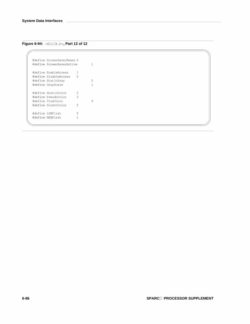
System Data Interfaces
Figure 6-94: < X 1 1 / X . h >, Part 12 of 12
# d e f i n e S c r e e n S a v e r R e s e t 0# d e f i n e S c r e e n S a v e r A c t i v e 1
# d e f i n e E n a b l e A c c e s s 1# d e f i n e D i s a b l e A c c e s s 0# d e f i n e S t a t i c G r a y 0# d e f i n e G r a y S c a l e 1
# d e f i n e S t a t i c C o l o r 2# d e f i n e P s e u d o C o l o r 3# d e f i n e T r u e C o l o r 4# d e f i n e D i r e c t C o l o r 5
# d e f i n e L S B F i r s t 0# d e f i n e M S B F i r s t 1
6-86 SPARC PROCESSOR SUPPLEMENT

System Data Interfaces
Figure 6-95: < X 1 1 / X a t o m . h >, Part 1 of 3
# d e f i n e X A _ P R I M A R Y ( ( A t o m ) 1 )# d e f i n e X A _ S E C O N D A R Y ( ( A t o m ) 2 )# d e f i n e X A _ A R C ( ( A t o m ) 3 )# d e f i n e X A _ A T O M ( ( A t o m ) 4 )# d e f i n e X A _ B I T M A P ( ( A t o m ) 5 )# d e f i n e X A _ C A R D I N A L ( ( A t o m ) 6 )# d e f i n e X A _ C O L O R M A P ( ( A t o m ) 7 )# d e f i n e X A _ C U R S O R ( ( A t o m ) 8 )# d e f i n e X A _ C U T _ B U F F E R 0 ( ( A t o m ) 9 )# d e f i n e X A _ C U T _ B U F F E R 1 ( ( A t o m ) 1 0 )# d e f i n e X A _ C U T _ B U F F E R 2 ( ( A t o m ) 1 1 )# d e f i n e X A _ C U T _ B U F F E R 3 ( ( A t o m ) 1 2 )# d e f i n e X A _ C U T _ B U F F E R 4 ( ( A t o m ) 1 3 )# d e f i n e X A _ C U T _ B U F F E R 5 ( ( A t o m ) 1 4 )# d e f i n e X A _ C U T _ B U F F E R 6 ( ( A t o m ) 1 5 )# d e f i n e X A _ C U T _ B U F F E R 7 ( ( A t o m ) 1 6 )# d e f i n e X A _ D R A W A B L E ( ( A t o m ) 1 7 )# d e f i n e X A _ F O N T ( ( A t o m ) 1 8 )# d e f i n e X A _ I N T E G E R ( ( A t o m ) 1 9 )# d e f i n e X A _ P I X M A P ( ( A t o m ) 2 0 )# d e f i n e X A _ P O I N T ( ( A t o m ) 2 1 )# d e f i n e X A _ R E C T A N G L E ( ( A t o m ) 2 2 )# d e f i n e X A _ R E S O U R C E _ M A N A G E R ( ( A t o m ) 2 3 )# d e f i n e X A _ R G B _ C O L O R _ M A P ( ( A t o m ) 2 4 )# d e f i n e X A _ R G B _ B E S T _ M A P ( ( A t o m ) 2 5 )# d e f i n e X A _ R G B _ B L U E _ M A P ( ( A t o m ) 2 6 )# d e f i n e X A _ R G B _ D E F A U L T _ M A P ( ( A t o m ) 2 7 )# d e f i n e X A _ R G B _ G R A Y _ M A P ( ( A t o m ) 2 8 )# d e f i n e X A _ R G B _ G R E E N _ M A P ( ( A t o m ) 2 9 )# d e f i n e X A _ R G B _ R E D _ M A P ( ( A t o m ) 3 0 )# d e f i n e X A _ S T R I N G ( ( A t o m ) 3 1 )# d e f i n e X A _ V I S U A L I D ( ( A t o m ) 3 2 )
LIBRARIES 6-87

System Data Interfaces
Figure 6-96: < X 1 1 / X a t o m . h >, Part 2 of 3
# d e f i n e X A _ W I N D O W ( ( A t o m ) 3 3 )# d e f i n e X A _ W M _ C O M M A N D ( ( A t o m ) 3 4 )# d e f i n e X A _ W M _ H I N T S ( ( A t o m ) 3 5 )# d e f i n e X A _ W M _ C L I E N T _ M A C H I N E ( ( A t o m ) 3 6 )# d e f i n e X A _ W M _ I C O N _ N A M E ( ( A t o m ) 3 7 )# d e f i n e X A _ W M _ I C O N _ S I Z E ( ( A t o m ) 3 8 )# d e f i n e X A _ W M _ N A M E ( ( A t o m ) 3 9 )# d e f i n e X A _ W M _ N O R M A L _ H I N T S ( ( A t o m ) 4 0 )# d e f i n e X A _ W M _ S I Z E _ H I N T S ( ( A t o m ) 4 1 )# d e f i n e X A _ W M _ Z O O M _ H I N T S ( ( A t o m ) 4 2 )# d e f i n e X A _ M I N _ S P A C E ( ( A t o m ) 4 3 )# d e f i n e X A _ N O R M _ S P A C E ( ( A t o m ) 4 4 )# d e f i n e X A _ M A X _ S P A C E ( ( A t o m ) 4 5 )# d e f i n e X A _ E N D _ S P A C E ( ( A t o m ) 4 6 )# d e f i n e X A _ S U P E R S C R I P T _ X ( ( A t o m ) 4 7 )# d e f i n e X A _ S U P E R S C R I P T _ Y ( ( A t o m ) 4 8 )# d e f i n e X A _ S U B S C R I P T _ X ( ( A t o m ) 4 9 )# d e f i n e X A _ S U B S C R I P T _ Y ( ( A t o m ) 5 0 )# d e f i n e X A _ U N D E R L I N E _ P O S I T I O N ( ( A t o m ) 5 1 )# d e f i n e X A _ U N D E R L I N E _ T H I C K N E S S ( ( A t o m ) 5 2 )# d e f i n e X A _ S T R I K E O U T _ A S C E N T ( ( A t o m ) 5 3 )# d e f i n e X A _ S T R I K E O U T _ D E S C E N T ( ( A t o m ) 5 4 )# d e f i n e X A _ I T A L I C _ A N G L E ( ( A t o m ) 5 5 )# d e f i n e X A _ X _ H E I G H T ( ( A t o m ) 5 6 )# d e f i n e X A _ Q U A D _ W I D T H ( ( A t o m ) 5 7 )# d e f i n e X A _ W E I G H T ( ( A t o m ) 5 8 )# d e f i n e X A _ P O I N T _ S I Z E ( ( A t o m ) 5 9 )# d e f i n e X A _ R E S O L U T I O N ( ( A t o m ) 6 0 )# d e f i n e X A _ C O P Y R I G H T ( ( A t o m ) 6 1 )# d e f i n e X A _ N O T I C E ( ( A t o m ) 6 2 )# d e f i n e X A _ F O N T _ N A M E ( ( A t o m ) 6 3 )# d e f i n e X A _ F A M I L Y _ N A M E ( ( A t o m ) 6 4 )
6-88 SPARC PROCESSOR SUPPLEMENT

System Data Interfaces
Figure 6-97: < X 1 1 / X a t o m . h >, Part 3 of 3
# d e f i n e X A _ F U L L _ N A M E ( ( A t o m ) 6 5 )# d e f i n e X A _ C A P _ H E I G H T ( ( A t o m ) 6 6 )# d e f i n e X A _ W M _ C L A S S ( ( A t o m ) 6 7 )# d e f i n e X A _ W M _ T R A N S I E N T _ F O R ( ( A t o m ) 6 8 )# d e f i n e X A _ L A S T _ P R E D E F I N E D ( ( A t o m ) 6 8 )
LIBRARIES 6-89

System Data Interfaces
Figure 6-98: < X 1 1 / X c m s . h >, Part 1 of 5
# d e f i n e X c m s F a i l u r e 0# d e f i n e X c m s S u c c e s s 1# d e f i n e X c m s S u c c e s s W i t h C o m p r e s s i o n 2
# d e f i n e X c m s U n d e f i n e d F o r m a t ( X c m s C o l o r F o r m a t ) 0 x 0 0 0 0 0 0 0 0# d e f i n e X c m s C I E X Y Z F o r m a t ( X c m s C o l o r F o r m a t ) 0 x 0 0 0 0 0 0 0 1# d e f i n e X c m s C I E u v Y F o r m a t ( X c m s C o l o r F o r m a t ) 0 x 0 0 0 0 0 0 0 2# d e f i n e X c m s C I E x y Y F o r m a t ( X c m s C o l o r F o r m a t ) 0 x 0 0 0 0 0 0 0 3# d e f i n e X c m s C I E L a b F o r m a t ( X c m s C o l o r F o r m a t ) 0 x 0 0 0 0 0 0 0 4# d e f i n e X c m s C I E L u v F o r m a t ( X c m s C o l o r F o r m a t ) 0 x 0 0 0 0 0 0 0 5# d e f i n e X c m s T e k H V C F o r m a t ( X c m s C o l o r F o r m a t ) 0 x 0 0 0 0 0 0 0 6# d e f i n e X c m s R G B F o r m a t ( X c m s C o l o r F o r m a t ) 0 x 8 0 0 0 0 0 0 0# d e f i n e X c m s R G B i F o r m a t ( X c m s C o l o r F o r m a t ) 0 x 8 0 0 0 0 0 0 1
# d e f i n e X c m s I n i t N o n e 0 x 0 0# d e f i n e X c m s I n i t S u c c e s s 0 x 0 1
t y p e d e f u n s i g n e d i n t X c m s C o l o r F o r m a t ;
t y p e d e f d o u b l e X c m s F l o a t ;
t y p e d e f s t r u c t {u n s i g n e d s h o r t r e d ;u n s i g n e d s h o r t g r e e n ;u n s i g n e d s h o r t b l u e ;
} X c m s R G B ;
6-90 SPARC PROCESSOR SUPPLEMENT

System Data Interfaces
Figure 6-99: < X 1 1 / X c m s . h >, Part 2 of 5
t y p e d e f s t r u c t {X c m s F l o a t r e d ;X c m s F l o a t g r e e n ;X c m s F l o a t b l u e ;
} X c m s R G B i ;
t y p e d e f s t r u c t {X c m s F l o a t X ;X c m s F l o a t Y ;X c m s F l o a t Z ;
} X c m s C I E X Y Z ;
t y p e d e f s t r u c t {X c m s F l o a t u _ p r i m e ;X c m s F l o a t v _ p r i m e ;X c m s F l o a t Y ;
} X c m s C I E u v Y ;
t y p e d e f s t r u c t {X c m s F l o a t x ;X c m s F l o a t y ;X c m s F l o a t Y ;
} X c m s C I E x y Y ;
t y p e d e f s t r u c t {X c m s F l o a t L _ s t a r ;X c m s F l o a t a _ s t a r ;X c m s F l o a t b _ s t a r ;
} X c m s C I E L a b ;
LIBRARIES 6-91

System Data Interfaces
Figure 6-100: < X 1 1 / X c m s . h >, Part 3 of 5
t y p e d e f s t r u c t {X c m s F l o a t L _ s t a r ;X c m s F l o a t u _ s t a r ;X c m s F l o a t v _ s t a r ;
} X c m s C I E L u v ;
t y p e d e f s t r u c t {X c m s F l o a t H ;X c m s F l o a t V ;X c m s F l o a t C ;
} X c m s T e k H V C ;
t y p e d e f s t r u c t {X c m s F l o a t p a d 0 ;X c m s F l o a t p a d 1 ;X c m s F l o a t p a d 2 ;X c m s F l o a t p a d 3 ;
} X c m s P a d ;
6-92 SPARC PROCESSOR SUPPLEMENT

System Data Interfaces
Figure 6-101: < X 1 1 / X c m s . h >, Part 4 of 5
t y p e d e f s t r u c t {u n i o n {
X c m s R G B R G B ;X c m s R G B i R G B i ;X c m s C I E X Y Z C I E X Y Z ;X c m s C I E u v Y C I E u v Y ;X c m s C I E x y Y C I E x y Y ;X c m s C I E L a b C I E L a b ;X c m s C I E L u v C I E L u v ;X c m s T e k H V C T e k H V C ;X c m s P a d P a d ;
} s p e c ;u n s i g n e d l o n g p i x e l ;X c m s C o l o r F o r m a t f o r m a t ;
} X c m s C o l o r ;
t y p e d e f s t r u c t {X c m s C o l o r s c r e e n W h i t e P t ;X P o i n t e r f u n c t i o n S e t ;X P o i n t e r s c r e e n D a t a ;u n s i g n e d c h a r s t a t e ;c h a r p a d [ 3 ] ;
} X c m s P e r S c r n I n f o ;
t y p e d e f v o i d * X c m s C C C ;
t y p e d e f S t a t u s ( * X c m s C o n v e r s i o n P r o c ) ( ) ;t y p e d e f X c m s C o n v e r s i o n P r o c * X c m s F u n c L i s t P t r ;
LIBRARIES 6-93

System Data Interfaces
Figure 6-102: < X 1 1 / X c m s . h >, Part 5 of 5
t y p e d e f s t r u c t {c h a r * p r e f i x ;X c m s C o l o r F o r m a t i d ;X c m s P a r s e S t r i n g P r o c p a r s e S t r i n g ;X c m s F u n c L i s t P t r t o _ C I E X Y Z ;X c m s F u n c L i s t P t r f r o m _ C I E X Y Z ;i n t i n v e r s e _ f l a g ;
} X c m s C o l o r S p a c e ;
t y p e d e f s t r u c t {X c m s C o l o r S p a c e * * D D C o l o r S p a c e s ;X c m s S c r e e n I n i t P r o c s c r e e n I n i t P r o c ;X c m s S c r e e n F r e e P r o c s c r e e n F r e e P r o c ;
} X c m s F u n c t i o n S e t ;
6-94 SPARC PROCESSOR SUPPLEMENT

System Data Interfaces
Figure 6-103: < X 1 1 / X l i b . h > Part 1 of 27
t y p e d e f v o i d * X P o i n t e r ;
# d e f i n e B o o l i n t# d e f i n e S t a t u s i n t# d e f i n e T r u e 1# d e f i n e F a l s e 0# d e f i n e Q u e u e d A l r e a d y 0# d e f i n e Q u e u e d A f t e r R e a d i n g 1# d e f i n e Q u e u e d A f t e r F l u s h 2
# d e f i n e A l l P l a n e s ( ( u n s i g n e d l o n g ) ̃ 0 L )
Figure 6-104: < X 1 1 / X l i b . h > Part 2 of 27
t y p d e f v o i d X E x t D a t a ;
t y p d e f v o i d X E x t C o d e s ;
t y p e d e f s t r u c t {i n t d e p t h ;i n t b i t s _ p e r _ p i x e l ;i n t s c a n l i n e _ p a d ;
} X P i x m a p F o r m a t V a l u e s ;
LIBRARIES 6-95

System Data Interfaces
Figure 6-105: < X 1 1 / X l i b . h > Part 3 of 27
t y p e d e f s t r u c t {i n t f u n c t i o n ;u n s i g n e d l o n g p l a n e _ m a s k ;u n s i g n e d l o n g f o r e g r o u n d ;u n s i g n e d l o n g b a c k g r o u n d ;i n t l i n e _ w i d t h ;i n t l i n e _ s t y l e ;i n t c a p _ s t y l e ;i n t j o i n _ s t y l e ;i n t f i l l _ s t y l e ;i n t f i l l _ r u l e ;i n t a r c _ m o d e ;P i x m a p t i l e ;P i x m a p s t i p p l e ;i n t t s _ x _ o r i g i n ;i n t t s _ y _ o r i g i n ;F o n t f o n t ;i n t s u b w i n d o w _ m o d e ;B o o l g r a p h i c s _ e x p o s u r e s ;i n t c l i p _ x _ o r i g i n ;i n t c l i p _ y _ o r i g i n ;P i x m a p c l i p _ m a s k ;i n t d a s h _ o f f s e t ;c h a r d a s h e s ;
} X G C V a l u e s ;
t y p e d e f v o i d * G C ;
t y p e d e f s t r u c t _ d u m m y V i s u a l ;
6-96 SPARC PROCESSOR SUPPLEMENT

System Data Interfaces
Figure 6-106: < X 1 1 / X l i b . h > Part 4 of 27
t y p e d e f s t r u c t _ d u m m y S c r e e n ;
t y p e d e f s t r u c t {P i x m a p b a c k g r o u n d _ p i x m a p ;u n s i g n e d l o n g b a c k g r o u n d _ p i x e l ;P i x m a p b o r d e r _ p i x m a p ;u n s i g n e d l o n g b o r d e r _ p i x e l ;i n t b i t _ g r a v i t y ;i n t w i n _ g r a v i t y ;i n t b a c k i n g _ s t o r e ;u n s i g n e d l o n g b a c k i n g _ p l a n e s ;u n s i g n e d l o n g b a c k i n g _ p i x e l ;B o o l s a v e _ u n d e r ;l o n g e v e n t _ m a s k ;l o n g d o _ n o t _ p r o p a g a t e _ m a s k ;B o o l o v e r r i d e _ r e d i r e c t ;C o l o r m a p c o l o r m a p ;C u r s o r c u r s o r ;
} X S e t W i n d o w A t t r i b u t e s ;
LIBRARIES 6-97

System Data Interfaces
Figure 6-107: < X 1 1 / X l i b . h > Part 5 of 27
t y p e d e f s t r u c t {X E x t D a t a * e x t _ d a t a ;i n t d e p t h ;i n t b i t s _ p e r _ p i x e l ;i n t s c a n l i n e _ p a d ;
} S c r e e n F o r m a t ;
t y p e d e f s t r u c t {i n t x , y ;i n t w i d t h , h e i g h t ;i n t b o r d e r _ w i d t h ;i n t d e p t h ;V i s u a l * v i s u a l ;W i n d o w r o o t ;i n t c l a s s ;i n t b i t _ g r a v i t y ;i n t w i n _ g r a v i t y ;i n t b a c k i n g _ s t o r e ;u n s i g n e d l o n g b a c k i n g _ p l a n e s ;u n s i g n e d l o n g b a c k i n g _ p i x e l ;B o o l s a v e _ u n d e r ;C o l o r m a p c o l o r m a p ;B o o l m a p _ i n s t a l l e d ;i n t m a p _ s t a t e ;l o n g a l l _ e v e n t _ m a s k s ;l o n g y o u r _ e v e n t _ m a s k ;l o n g d o _ n o t _ p r o p a g a t e _ m a s k ;B o o l o v e r r i d e _ r e d i r e c t ;S c r e e n * s c r e e n ;
} X W i n d o w A t t r i b u t e s ;
6-98 SPARC PROCESSOR SUPPLEMENT

System Data Interfaces
Figure 6-108: < X 1 1 / X l i b . h > Part 6 of 27
t y p e d e f s t r u c t {i n t f a m i l y ;i n t l e n g t h ;c h a r * a d d r e s s ;
} X H o s t A d d r e s s ;
t y p e d e f s t r u c t _ X I m a g e {i n t w i d t h , h e i g h t ;i n t x o f f s e t ;i n t f o r m a t ;c h a r * d a t a ;i n t b y t e _ o r d e r ;i n t b i t m a p _ u n i t ;i n t b i t m a p _ b i t _ o r d e r ;i n t b i t m a p _ p a d ;i n t d e p t h ;i n t b y t e s _ p e r _ l i n e ;i n t b i t s _ p e r _ p i x e l ;u n s i g n e d l o n g r e d _ m a s k ;u n s i g n e d l o n g g r e e n _ m a s k ;u n s i g n e d l o n g b l u e _ m a s k ;X P o i n t e r o b d a t a ;s t r u c t f u n c s {
s t r u c t _ X I m a g e * ( * c r e a t e _ i m a g e ) ( ) ;i n t ( * d e s t r o y _ i m a g e ) ( ) ;u n s i g n e d l o n g ( * g e t _ p i x e l ) ( ) ;i n t ( * p u t _ p i x e l ) ( ) ;s t r u c t _ X I m a g e * ( * s u b _ i m a g e ) ( ) ;i n t ( * a d d _ p i x e l ) ( ) ;
} f ;} X I m a g e ;
LIBRARIES 6-99

System Data Interfaces
Figure 6-109: < X 1 1 / X l i b . h > Part 7 of 27
t y p e d e f s t r u c t {i n t x , y ;i n t w i d t h , h e i g h t ;i n t b o r d e r _ w i d t h ;W i n d o w s i b l i n g ;i n t s t a c k _ m o d e ;
} X W i n d o w C h a n g e s ;
t y p e d e f s t r u c t {u n s i g n e d l o n g p i x e l ;u n s i g n e d s h o r t r e d , g r e e n , b l u e ;c h a r f l a g s ;c h a r p a d ;
} X C o l o r ;
t y p e d e f s t r u c t {s h o r t x 1 , y 1 , x 2 , y 2 ;
} X S e g m e n t ;
t y p e d e f s t r u c t {s h o r t x , y ;
} X P o i n t ;
t y p e d e f s t r u c t {s h o r t x , y ;u n s i g n e d s h o r t w i d t h , h e i g h t ;
} X R e c t a n g l e ;
t y p e d e f s t r u c t {s h o r t x , y ;u n s i g n e d s h o r t w i d t h , h e i g h t ;s h o r t a n g l e 1 , a n g l e 2 ;
} X A r c ;
6-100 SPARC PROCESSOR SUPPLEMENT

System Data Interfaces
Figure 6-110: < X 1 1 / X l i b . h > Part 8 of 27
t y p e d e f s t r u c t {i n t k e y _ c l i c k _ p e r c e n t ;i n t b e l l _ p e r c e n t ;i n t b e l l _ p i t c h ;i n t b e l l _ d u r a t i o n ;i n t l e d ;i n t l e d _ m o d e ;i n t k e y ;i n t a u t o _ r e p e a t _ m o d e ;
} X K e y b o a r d C o n t r o l ;
t y p e d e f s t r u c t {i n t k e y _ c l i c k _ p e r c e n t ;i n t b e l l _ p e r c e n t ;u n s i g n e d i n t b e l l _ p i t c h , b e l l _ d u r a t i o n ;u n s i g n e d l o n g l e d _ m a s k ;i n t g l o b a l _ a u t o _ r e p e a t ;c h a r a u t o _ r e p e a t s [ 3 2 ] ;
} X K e y b o a r d S t a t e ;t y p e d e f s t r u c t {
T i m e t i m e ;s h o r t x , y ;
} X T i m e C o o r d ;
t y p e d e f s t r u c t {i n t m a x _ k e y p e r m o d ;K e y C o d e * m o d i f i e r m a p ;
} X M o d i f i e r K e y m a p ;
t y p e d e f s t r u c t _ d u m m y D i s p l a y ;
LIBRARIES 6-101

System Data Interfaces
Figure 6-111: < X 1 1 / X l i b . h > Part 9 of 27
t y p e d e f s t r u c t {i n t t y p e ;u n s i g n e d l o n g s e r i a l ;B o o l s e n d _ e v e n t ;D i s p l a y * d i s p l a y ;W i n d o w w i n d o w ;W i n d o w r o o t ;W i n d o w s u b w i n d o w ;T i m e t i m e ;i n t x , y ;i n t x _ r o o t , y _ r o o t ;u n s i g n e d i n t s t a t e ;u n s i g n e d i n t k e y c o d e ;B o o l s a m e _ s c r e e n ;
} X K e y E v e n t ;t y p e d e f X K e y E v e n t X K e y P r e s s e d E v e n t ;t y p e d e f X K e y E v e n t X K e y R e l e a s e d E v e n t ;
t y p e d e f s t r u c t {i n t t y p e ;u n s i g n e d l o n g s e r i a l ;B o o l s e n d _ e v e n t ;D i s p l a y * d i s p l a y ;W i n d o w w i n d o w ;W i n d o w r o o t ;W i n d o w s u b w i n d o w ;T i m e t i m e ;i n t x , y ;i n t x _ r o o t , y _ r o o t ;u n s i g n e d i n t s t a t e ;u n s i g n e d i n t b u t t o n ;B o o l s a m e _ s c r e e n ;
} X B u t t o n E v e n t ;t y p e d e f X B u t t o n E v e n t X B u t t o n P r e s s e d E v e n t ;t y p e d e f X B u t t o n E v e n t X B u t t o n R e l e a s e d E v e n t ;
6-102 SPARC PROCESSOR SUPPLEMENT

System Data Interfaces
Figure 6-112: < X 1 1 / X l i b . h > Part 10 of 27
t y p e d e f s t r u c t {i n t t y p e ;u n s i g n e d l o n g s e r i a l ;B o o l s e n d _ e v e n t ;D i s p l a y * d i s p l a y ;W i n d o w w i n d o w ;W i n d o w r o o t ;W i n d o w s u b w i n d o w ;T i m e t i m e ;i n t x , y ;i n t x _ r o o t , y _ r o o t ;u n s i g n e d i n t s t a t e ;c h a r i s _ h i n t ;B o o l s a m e _ s c r e e n ;
} X M o t i o n E v e n t ;t y p e d e f X M o t i o n E v e n t X P o i n t e r M o v e d E v e n t ;
t y p e d e f s t r u c t {i n t t y p e ;u n s i g n e d l o n g s e r i a l ;B o o l s e n d _ e v e n t ;D i s p l a y * d i s p l a y ;W i n d o w w i n d o w ;W i n d o w r o o t ;W i n d o w s u b w i n d o w ;T i m e t i m e ;i n t x , y ;i n t x _ r o o t , y _ r o o t ;i n t m o d e ;i n t d e t a i l ;B o o l s a m e _ s c r e e n ;B o o l f o c u s ;u n s i g n e d i n t s t a t e ;
} X C r o s s i n g E v e n t ;
LIBRARIES 6-103

System Data Interfaces
Figure 6-113: < X 1 1 / X l i b . h > Part 11 of 27
t y p e d e f X C r o s s i n g E v e n t X E n t e r W i n d o w E v e n t ;t y p e d e f X C r o s s i n g E v e n t X L e a v e W i n d o w E v e n t ;t y p e d e f s t r u c t {
i n t t y p e ;u n s i g n e d l o n g s e r i a l ;B o o l s e n d _ e v e n t ;D i s p l a y * d i s p l a y ;W i n d o w w i n d o w ;i n t m o d e ;i n t d e t a i l ;
} X F o c u s C h a n g e E v e n t ;t y p e d e f X F o c u s C h a n g e E v e n t X F o c u s I n E v e n t ;t y p e d e f X F o c u s C h a n g e E v e n t X F o c u s O u t E v e n t ;
t y p e d e f s t r u c t {i n t t y p e ;u n s i g n e d l o n g s e r i a l ;B o o l s e n d _ e v e n t ;D i s p l a y * d i s p l a y ;W i n d o w w i n d o w ;c h a r k e y _ v e c t o r [ 3 2 ] ;
} X K e y m a p E v e n t ;
t y p e d e f s t r u c t {i n t t y p e ;u n s i g n e d l o n g s e r i a l ;B o o l s e n d _ e v e n t ;D i s p l a y * d i s p l a y ;W i n d o w w i n d o w ;i n t x , y ;i n t w i d t h , h e i g h t ;i n t c o u n t ;
} X E x p o s e E v e n t ;
6-104 SPARC PROCESSOR SUPPLEMENT

System Data Interfaces
Figure 6-114: < X 1 1 / X l i b . h > Part 12 of 27
t y p e d e f s t r u c t {i n t t y p e ;u n s i g n e d l o n g s e r i a l ;B o o l s e n d _ e v e n t ;D i s p l a y * d i s p l a y ;D r a w a b l e d r a w a b l e ;i n t x , y ;i n t w i d t h , h e i g h t ;i n t c o u n t ;i n t m a j o r _ c o d e ;i n t m i n o r _ c o d e ;
} X G r a p h i c s E x p o s e E v e n t ;
t y p e d e f s t r u c t {i n t t y p e ;u n s i g n e d l o n g s e r i a l ;B o o l s e n d _ e v e n t ;D i s p l a y * d i s p l a y ;D r a w a b l e d r a w a b l e ;i n t m a j o r _ c o d e ;i n t m i n o r _ c o d e ;
} X N o E x p o s e E v e n t ;
t y p e d e f s t r u c t {i n t t y p e ;u n s i g n e d l o n g s e r i a l ;B o o l s e n d _ e v e n t ;D i s p l a y * d i s p l a y ;W i n d o w w i n d o w ;i n t s t a t e ;
} X V i s i b i l i t y E v e n t ;
LIBRARIES 6-105

System Data Interfaces
Figure 6-115: < X 1 1 / X l i b . h > Part 13 of 27
t y p e d e f s t r u c t {i n t t y p e ;u n s i g n e d l o n g s e r i a l ;B o o l s e n d _ e v e n t ;D i s p l a y * d i s p l a y ;W i n d o w p a r e n t ;W i n d o w w i n d o w ;i n t x , y ;i n t w i d t h , h e i g h t ;i n t b o r d e r _ w i d t h ;B o o l o v e r r i d e _ r e d i r e c t ;
} X C r e a t e W i n d o w E v e n t ;
t y p e d e f s t r u c t {i n t t y p e ;u n s i g n e d l o n g s e r i a l ;B o o l s e n d _ e v e n t ;D i s p l a y * d i s p l a y ;W i n d o w e v e n t ;W i n d o w w i n d o w ;
} X D e s t r o y W i n d o w E v e n t ;
t y p e d e f s t r u c t {i n t t y p e ;u n s i g n e d l o n g s e r i a l ;B o o l s e n d _ e v e n t ;D i s p l a y * d i s p l a y ;W i n d o w e v e n t ;W i n d o w w i n d o w ;B o o l f r o m _ c o n f i g u r e ;
} X U n m a p E v e n t ;
6-106 SPARC PROCESSOR SUPPLEMENT

System Data Interfaces
Figure 6-116: < X 1 1 / X l i b . h > Part 14 of 27
t y p e d e f s t r u c t {i n t t y p e ;u n s i g n e d l o n g s e r i a l ;B o o l s e n d _ e v e n t ;D i s p l a y * d i s p l a y ;W i n d o w e v e n t ;W i n d o w w i n d o w ;B o o l o v e r r i d e _ r e d i r e c t ;
} X M a p E v e n t ;
t y p e d e f s t r u c t {i n t t y p e ;u n s i g n e d l o n g s e r i a l ;B o o l s e n d _ e v e n t ;D i s p l a y * d i s p l a y ;W i n d o w p a r e n t ;W i n d o w w i n d o w ;
} X M a p R e q u e s t E v e n t ;
t y p e d e f s t r u c t {i n t t y p e ;u n s i g n e d l o n g s e r i a l ;B o o l s e n d _ e v e n t ;D i s p l a y * d i s p l a y ;W i n d o w e v e n t ;W i n d o w w i n d o w ;W i n d o w p a r e n t ;i n t x , y ;B o o l o v e r r i d e _ r e d i r e c t ;
} X R e p a r e n t E v e n t ;
LIBRARIES 6-107

System Data Interfaces
Figure 6-117: < X 1 1 / X l i b . h > Part 15 of 27
t y p e d e f s t r u c t {i n t t y p e ;u n s i g n e d l o n g s e r i a l ;B o o l s e n d _ e v e n t ;D i s p l a y * d i s p l a y ;W i n d o w e v e n t ;W i n d o w w i n d o w ;i n t x , y ;i n t w i d t h , h e i g h t ;i n t b o r d e r _ w i d t h ;W i n d o w a b o v e ;B o o l o v e r r i d e _ r e d i r e c t ;
} X C o n f i g u r e E v e n t ;
t y p e d e f s t r u c t {i n t t y p e ;u n s i g n e d l o n g s e r i a l ;B o o l s e n d _ e v e n t ;D i s p l a y * d i s p l a y ;W i n d o w e v e n t ;W i n d o w w i n d o w ;i n t x , y ;
} X G r a v i t y E v e n t ;
t y p e d e f s t r u c t {i n t t y p e ;u n s i g n e d l o n g s e r i a l ;B o o l s e n d _ e v e n t ;D i s p l a y * d i s p l a y ;W i n d o w w i n d o w ;i n t w i d t h , h e i g h t ;
} X R e s i z e R e q u e s t E v e n t ;
6-108 SPARC PROCESSOR SUPPLEMENT

System Data Interfaces
Figure 6-118: < X 1 1 / X l i b . h > Part 16 of 27
t y p e d e f s t r u c t {i n t t y p e ;u n s i g n e d l o n g s e r i a l ;B o o l s e n d _ e v e n t ;D i s p l a y * d i s p l a y ;W i n d o w p a r e n t ;W i n d o w w i n d o w ;i n t x , y ;i n t w i d t h , h e i g h t ;i n t b o r d e r _ w i d t h ;W i n d o w a b o v e ;i n t d e t a i l ;u n s i g n e d l o n g v a l u e _ m a s k ;
} X C o n f i g u r e R e q u e s t E v e n t ;
t y p e d e f s t r u c t {i n t t y p e ;u n s i g n e d l o n g s e r i a l ;B o o l s e n d _ e v e n t ;D i s p l a y * d i s p l a y ;W i n d o w e v e n t ;W i n d o w w i n d o w ;i n t p l a c e ;
} X C i r c u l a t e E v e n t ;
t y p e d e f s t r u c t {i n t t y p e ;u n s i g n e d l o n g s e r i a l ;B o o l s e n d _ e v e n t ;D i s p l a y * d i s p l a y ;W i n d o w p a r e n t ;W i n d o w w i n d o w ;i n t p l a c e ;
} X C i r c u l a t e R e q u e s t E v e n t ;
LIBRARIES 6-109

System Data Interfaces
Figure 6-119: < X 1 1 / X l i b . h > Part 17 of 27
t y p e d e f s t r u c t {i n t t y p e ;u n s i g n e d l o n g s e r i a l ;B o o l s e n d _ e v e n t ;D i s p l a y * d i s p l a y ;W i n d o w w i n d o w ;A t o m a t o m ;T i m e t i m e ;i n t s t a t e ;
} X P r o p e r t y E v e n t ;
t y p e d e f s t r u c t {i n t t y p e ;u n s i g n e d l o n g s e r i a l ;B o o l s e n d _ e v e n t ;D i s p l a y * d i s p l a y ;W i n d o w w i n d o w ;A t o m s e l e c t i o n ;T i m e t i m e ;
} X S e l e c t i o n C l e a r E v e n t ;
t y p e d e f s t r u c t {i n t t y p e ;u n s i g n e d l o n g s e r i a l ;B o o l s e n d _ e v e n t ;D i s p l a y * d i s p l a y ;W i n d o w o w n e r ;W i n d o w r e q u e s t o r ;A t o m s e l e c t i o n ;A t o m t a r g e t ;A t o m p r o p e r t y ;T i m e t i m e ;
} X S e l e c t i o n R e q u e s t E v e n t ;
6-110 SPARC PROCESSOR SUPPLEMENT

System Data Interfaces
Figure 6-120: < X 1 1 / X l i b . h > Part 18 of 27
t y p e d e f s t r u c t {i n t t y p e ;u n s i g n e d l o n g s e r i a l ;B o o l s e n d _ e v e n t ;D i s p l a y * d i s p l a y ;W i n d o w r e q u e s t o r ;A t o m s e l e c t i o n ;A t o m t a r g e t ;A t o m p r o p e r t y ;T i m e t i m e ;
} X S e l e c t i o n E v e n t ;
t y p e d e f s t r u c t {i n t t y p e ;D i s p l a y * d i s p l a y ;X I D r e s o u r c e i d ;u n s i g n e d l o n g s e r i a l ;u n s i g n e d c h a r e r r o r _ c o d e ;u n s i g n e d c h a r r e q u e s t _ c o d e ;u n s i g n e d c h a r m i n o r _ c o d e ;
} X E r r o r E v e n t ;
t y p e d e f s t r u c t {i n t t y p e ;u n s i g n e d l o n g s e r i a l ;B o o l s e n d _ e v e n t ;D i s p l a y * d i s p l a y ;W i n d o w w i n d o w ;A t o m m e s s a g e _ t y p e ;i n t f o r m a t ;u n i o n {
c h a r b [ 2 0 ] ;s h o r t s [ 1 0 ] ;l o n g l [ 5 ] ;
} d a t a ;} X C l i e n t M e s s a g e E v e n t ;
LIBRARIES 6-111

System Data Interfaces
Figure 6-121: < X 1 1 / X l i b . h > Part 19 of 27
t y p e d e f s t r u c t {i n t t y p e ;u n s i g n e d l o n g s e r i a l ;B o o l s e n d _ e v e n t ;D i s p l a y * d i s p l a y ;W i n d o w w i n d o w ;C o l o r m a p c o l o r m a p ;B o o l n e w ;i n t s t a t e ;
} X C o l o r m a p E v e n t ;
t y p e d e f s t r u c t {i n t t y p e ;u n s i g n e d l o n g s e r i a l ;B o o l s e n d _ e v e n t ;D i s p l a y * d i s p l a y ;W i n d o w w i n d o w ;i n t r e q u e s t ;i n t f i r s t _ k e y c o d e ;i n t c o u n t ;
} X M a p p i n g E v e n t ;
t y p e d e f s t r u c t {i n t t y p e ;u n s i g n e d l o n g s e r i a l ;B o o l s e n d _ e v e n t ;D i s p l a y * d i s p l a y ;W i n d o w w i n d o w ;
} X A n y E v e n t ;
6-112 SPARC PROCESSOR SUPPLEMENT

System Data Interfaces
Figure 6-122: < X 1 1 / X l i b . h > Part 20 of 27
t y p e d e f u n i o n _ X E v e n t {i n t t y p e ;X A n y E v e n t x a n y ;X K e y E v e n t x k e y ;X B u t t o n E v e n t x b u t t o n ;X M o t i o n E v e n t x m o t i o n ;X C r o s s i n g E v e n t x c r o s s i n g ;X F o c u s C h a n g e E v e n t x f o c u s ;X E x p o s e E v e n t x e x p o s e ;X G r a p h i c s E x p o s e E v e n t x g r a p h i c s e x p o s e ;X N o E x p o s e E v e n t x n o e x p o s e ;X V i s i b i l i t y E v e n t x v i s i b i l i t y ;X C r e a t e W i n d o w E v e n t x c r e a t e w i n d o w ;X D e s t r o y W i n d o w E v e n t x d e s t r o y w i n d o w ;X U n m a p E v e n t x u n m a p ;X M a p E v e n t x m a p ;X M a p R e q u e s t E v e n t x m a p r e q u e s t ;X R e p a r e n t E v e n t x r e p a r e n t ;X C o n f i g u r e E v e n t x c o n f i g u r e ;X G r a v i t y E v e n t x g r a v i t y ;X R e s i z e R e q u e s t E v e n t x r e s i z e r e q u e s t ;X C o n f i g u r e R e q u e s t E v e n t x c o n f i g u r e r e q u e s t ;X C i r c u l a t e E v e n t x c i r c u l a t e ;X C i r c u l a t e R e q u e s t E v e n t x c i r c u l a t e r e q u e s t ;X P r o p e r t y E v e n t x p r o p e r t y ;X S e l e c t i o n C l e a r E v e n t x s e l e c t i o n c l e a r ;X S e l e c t i o n R e q u e s t E v e n t x s e l e c t i o n r e q u e s t ;X S e l e c t i o n E v e n t x s e l e c t i o n ;X C o l o r m a p E v e n t x c o l o r m a p ;X C l i e n t M e s s a g e E v e n t x c l i e n t ;X M a p p i n g E v e n t x m a p p i n g ;X E r r o r E v e n t x e r r o r ;X K e y m a p E v e n t x k e y m a p ;l o n g p a d [ 2 4 ] ;
} X E v e n t ;
LIBRARIES 6-113

System Data Interfaces
Figure 6-123: < X 1 1 / X l i b . h > Part 21 of 27
# d e f i n e X A l l o c I D ( d p y ) ( ( * ( d p y ) - > r e s o u r c e _ a l l o c ) ( ( d p y ) ) )
t y p e d e f s t r u c t {s h o r t l b e a r i n g ;s h o r t r b e a r i n g ;s h o r t w i d t h ;s h o r t a s c e n t ;s h o r t d e s c e n t ;u n s i g n e d s h o r t a t t r i b u t e s ;
} X C h a r S t r u c t ;
t y p e d e f s t r u c t {A t o m n a m e ;u n s i g n e d l o n g c a r d 3 2 ;
} X F o n t P r o p ;
t y p e d e f s t r u c t {X E x t D a t a * e x t _ d a t a ;F o n t f i d ;u n s i g n e d d i r e c t i o n ;u n s i g n e d m i n _ c h a r _ o r _ b y t e 2 ;u n s i g n e d m a x _ c h a r _ o r _ b y t e 2 ;u n s i g n e d m i n _ b y t e 1 ;u n s i g n e d m a x _ b y t e 1 ;B o o l a l l _ c h a r s _ e x i s t ;u n s i g n e d d e f a u l t _ c h a r ;i n t n _ p r o p e r t i e s ;X F o n t P r o p * p r o p e r t i e s ;X C h a r S t r u c t m i n _ b o u n d s ;X C h a r S t r u c t m a x _ b o u n d s ;X C h a r S t r u c t * p e r _ c h a r ;i n t a s c e n t ;i n t d e s c e n t ;
} X F o n t S t r u c t ;
6-114 SPARC PROCESSOR SUPPLEMENT

System Data Interfaces
Figure 6-124: < X 1 1 / X l i b . h > Part 22 of 27
t y p e d e f s t r u c t {c h a r * c h a r s ;i n t n c h a r s ;i n t d e l t a ;F o n t f o n t ;
} X T e x t I t e m ;
t y p e d e f s t r u c t {u n s i g n e d c h a r b y t e 1 ;u n s i g n e d c h a r b y t e 2 ;
} X C h a r 2 b ;
t y p e d e f s t r u c t {X C h a r 2 b * c h a r s ;i n t n c h a r s ;i n t d e l t a ;F o n t f o n t ;
} X T e x t I t e m 1 6 ;
t y p e d e f u n i o n {D i s p l a y * d i s p l a y ;G C g c ;V i s u a l * v i s u a l ;S c r e e n * s c r e e n ;S c r e e n F o r m a t * p i x m a p _ f o r m a t ;X F o n t S t r u c t * f o n t ;
} X E D a t a O b j e c t ;
t y p e d e f s t r u c t {X R e c t a n g l e m a x _ i n k _ e x t e n t ;X R e c t a n g l e m a x _ l o g i c a l _ e x t e n t ;
} X F o n t S e t E x t e n t s ;
t y p e d e f s t r u c t _ d u m m y X F o n t S e t ;
LIBRARIES 6-115

System Data Interfaces
Figure 6-125: < X 1 1 / X l i b . h > Part 23 of 27
t y p e d e f s t r u c t {c h a r * c h a r s ;i n t n c h a r s ;i n t d e l t a ;X F o n t S e t * f o n t _ s e t ;
} X m b T e x t I t e m ;
t y p e d e f s t r u c t {w c h a r _ t * c h a r s ;i n t n c h a r s ;i n t d e l t a ;X F o n t S e t f o n t _ s e t ;
} X w c T e x t I t e m ;
t y p e d e f v o i d ( * X I M P r o c ) ( ) ;
t y p e d e f v o i d * X I M ;t y p e d e f v o i d * X I C ;
t y p e d e f u n s i g n e d l o n g X I M S t y l e ;
t y p e d e f s t r u c t {u n s i g n e d s h o r t c o u n t _ s t y l e s ;X I M S t y l e * s u p p o r t e d _ s t y l e s ;
} X I M S t y l e s ;
# d e f i n e X I M P r e e d i t A r e a 0 x 0 0 0 1 L# d e f i n e X I M P r e e d i t C a l l b a c k s 0 x 0 0 0 2 L# d e f i n e X I M P r e e d i t P o s i t i o n 0 x 0 0 0 4 L# d e f i n e X I M P r e e d i t N o t h i n g 0 x 0 0 0 8 L# d e f i n e X I M P r e e d i t N o n e 0 x 0 0 1 0 L# d e f i n e X I M S t a t u s A r e a 0 x 0 1 0 0 L# d e f i n e X I M S t a t u s C a l l b a c k s 0 x 0 2 0 0 L# d e f i n e X I M S t a t u s N o t h i n g 0 x 0 4 0 0 L# d e f i n e X I M S t a t u s N o n e 0 x 0 8 0 0 L
6-116 SPARC PROCESSOR SUPPLEMENT

System Data Interfaces
Figure 6-126: < X 1 1 / X l i b . h > Part 24 of 27
# d e f i n e X N V a N e s t e d L i s t " X N V a N e s t e d L i s t "# d e f i n e X N Q u e r y I n p u t S t y l e " q u e r y I n p u t S t y l e "# d e f i n e X N C l i e n t W i n d o w " c l i e n t W i n d o w "# d e f i n e X N I n p u t S t y l e " i n p u t S t y l e "# d e f i n e X N F o c u s W i n d o w " f o c u s W i n d o w "# d e f i n e X N R e s o u r c e N a m e " r e s o u r c e N a m e "# d e f i n e X N R e s o u r c e C l a s s " r e s o u r c e C l a s s "# d e f i n e X N G e o m e t r y C a l l b a c k " g e o m e t r y C a l l b a c k "# d e f i n e X N F i l t e r E v e n t s " f i l t e r E v e n t s "# d e f i n e X N P r e e d i t S t a r t C a l l b a c k " p r e e d i t S t a r t C a l l b a c k "# d e f i n e X N P r e e d i t D o n e C a l l b a c k " p r e e d i t D o n e C a l l b a c k "# d e f i n e X N P r e e d i t D r a w C a l l b a c k " p r e e d i t D r a w C a l l b a c k "# d e f i n e X N P r e e d i t C a r e t C a l l b a c k " p r e e d i t C a r e t C a l l b a c k "# d e f i n e X N P r e e d i t A t t r i b u t e s " p r e e d i t A t t r i b u t e s "# d e f i n e X N S t a t u s S t a r t C a l l b a c k " s t a t u s S t a r t C a l l b a c k "# d e f i n e X N S t a t u s D o n e C a l l b a c k " s t a t u s D o n e C a l l b a c k "# d e f i n e X N S t a t u s D r a w C a l l b a c k " s t a t u s D r a w C a l l b a c k "# d e f i n e X N S t a t u s A t t r i b u t e s " s t a t u s A t t r i b u t e s "# d e f i n e X N A r e a " a r e a "# d e f i n e X N A r e a N e e d e d " a r e a N e e d e d "# d e f i n e X N S p o t L o c a t i o n " s p o t L o c a t i o n "# d e f i n e X N C o l o r m a p " c o l o r M a p "# d e f i n e X N S t d C o l o r m a p " s t d C o l o r M a p "# d e f i n e X N F o r e g r o u n d " f o r e g r o u n d "# d e f i n e X N B a c k g r o u n d " b a c k g r o u n d "# d e f i n e X N B a c k g r o u n d P i x m a p " b a c k g r o u n d P i x m a p "# d e f i n e X N F o n t S e t " f o n t S e t "# d e f i n e X N L i n e S p a c e " l i n e S p a c e "# d e f i n e X N C u r s o r " c u r s o r "
LIBRARIES 6-117

System Data Interfaces
Figure 6-127: < X 1 1 / X l i b . h > Part 25 of 27
# d e f i n e X B u f f e r O v e r f l o w - 1# d e f i n e X L o o k u p N o n e 1# d e f i n e X L o o k u p C h a r s 2# d e f i n e X L o o k u p K e y S y m 3# d e f i n e X L o o k u p B o t h 4
t y p e d e f X P o i n t e r X V a N e s t e d L i s t ;
t y p e d e f s t r u c t {X P o i n t e r c l i e n t _ d a t a ;X I M P r o c c a l l b a c k ;
} X I M C a l l b a c k ;
t y p e d e f u n s i g n e d l o n g X I M F e e d b a c k ;
# d e f i n e X I M R e v e r s e 1# d e f i n e X I M U n d e r l i n e ( 1 < < 1 )# d e f i n e X I M H i g h l i g h t ( 1 < < 2 )# d e f i n e X I M P r i m a r y ( 1 < < 5 )# d e f i n e X I M S e c o n d a r y ( 1 < < 6 )# d e f i n e X I M T e r t i a r y ( 1 < < 7 )
t y p e d e f s t r u c t _ X I M T e x t {u n s i g n e d s h o r t l e n g t h ;X I M F e e d b a c k * f e e d b a c k ;B o o l e n c o d i n g _ i s _ w c h a r ;u n i o n {
c h a r * m u l t i _ b y t e ;w c h a r _ t * w i d e _ c h a r ;
} s t r i n g ;} X I M T e x t ;
6-118 SPARC PROCESSOR SUPPLEMENT

System Data Interfaces
Figure 6-128: < X 1 1 / X l i b . h > Part 26 of 27
t y p e d e f s t r u c t _ X I M P r e e d i t D r a w C a l l b a c k S t r u c t {i n t c a r e t ;i n t c h g _ f i r s t ;i n t c h g _ l e n g t h ;X I M T e x t * t e x t ;
} X I M P r e e d i t D r a w C a l l b a c k S t r u c t ;
t y p e d e f e n u m {X I M F o r w a r d C h a r , X I M B a c k w a r d C h a r ,X I M F o r w a r d W o r d , X I M B a c k w a r d W o r d ,X I M C a r e t U p , X I M C a r e t D o w n ,X I M N e x t L i n e , X I M P r e v i o u s L i n e ,X I M L i n e S t a r t , X I M L i n e E n d ,X I M A b s o l u t e P o s i t i o n ,X I M D o n t C h a n g e
} X I M C a r e t D i r e c t i o n ;
t y p e d e f e n u m {X I M I s I n v i s i b l e ,X I M I s P r i m a r y ,X I M I s S e c o n d a r y
} X I M C a r e t S t y l e ;
t y p e d e f s t r u c t _ X I M P r e e d i t C a r e t C a l l b a c k S t r u c t {i n t p o s i t i o n ;X I M C a r e t D i r e c t i o n d i r e c t i o n ;X I M C a r e t S t y l e s t y l e ;
} X I M P r e e d i t C a r e t C a l l b a c k S t r u c t ;
Figure 6-129: < X 1 1 / X l i b . h > Part 27 of 27
t y p e d e f e n u m {X I M T e x t T y p e ,X I M B i t m a p T y p e
} X I M S t a t u s D a t a T y p e ;
t y p e d e f s t r u c t _ X I M S t a t u s D r a w C a l l b a c k S t r u c t {X I M S t a t u s D a t a T y p e t y p e ;u n i o n {
X I M T e x t * t e x t ;P i x m a p b i t m a p ;
} d a t a ;} X I M S t a t u s D r a w C a l l b a c k S t r u c t ;
LIBRARIES 6-119

System Data Interfaces
Figure 6-130: < X 1 1 / X r e s o u r c e . h >, Part 1 of 2
t y p e d e f i n t X r m Q u a r k , * X r m Q u a r k L i s t ;# d e f i n e N U L L Q U A R K ( ( X r m Q u a r k ) 0 )
t y p e d e f e n u m { X r m B i n d T i g h t l y , X r m B i n d L o o s e l y } \X r m B i n d i n g , * X r m B i n d i n g L i s t ;
t y p e d e f X r m Q u a r k X r m N a m e ;t y p e d e f X r m Q u a r k L i s t X r m N a m e L i s t ;t y p e d e f X r m Q u a r k X r m C l a s s ;t y p e d e f X r m Q u a r k L i s t X r m C l a s s L i s t ;t y p e d e f X r m Q u a r k X r m R e p r e s e n t a t i o n ;
# d e f i n e X r m S t r i n g T o N a m e ( s t r i n g ) X r m S t r i n g T o Q u a r k ( s t r i n g )# d e f i n e X r m S t r i n g T o N a m e L i s t ( s t r , n a m e ) X r m S t r i n g T o Q u a r k L i s t ( s t r , n a m e )# d e f i n e X r m S t r i n g T o C l a s s ( c l a s s ) X r m S t r i n g T o Q u a r k ( c l a s s )# d e f i n e X r m S t r i n g T o C l a s s L i s t ( s t r , c l a s s ) X r m S t r i n g T o Q u a r k L i s t ( s t r , c l a s s )# d e f i n e X r m S t r i n g T o R e p r e s e n t a t i o n ( s t r i n g ) \
X r m S t r i n g T o Q u a r k ( s t r i n g )
t y p e d e f s t r u c t {u n s i g n e d i n t s i z e ;X P o i n t e r a d d r ;
} X r m V a l u e , * X r m V a l u e P t r ;
t y p e d e f v o i d * X r m H a s h B u c k e t ;t y p e d e f X r m H a s h B u c k e t * X r m H a s h T a b l e ;t y p e d e f X r m H a s h T a b l e X r m S e a r c h L i s t [ ] ;t y p e d e f v o i d * X r m D a t a b a s e ;
# d e f i n e X r m E n u m A l l L e v e l s 0# d e f i n e X r m E n u m O n e L e v e l 1
6-120 SPARC PROCESSOR SUPPLEMENT

System Data Interfaces
Figure 6-131: < X 1 1 / X r e s o u r c e . h >, Part 2 of 2
t y p e d e f e n u m {X r m o p t i o n N o A r g ,X r m o p t i o n I s A r g ,X r m o p t i o n S t i c k y A r g ,X r m o p t i o n S e p A r g ,X r m o p t i o n R e s A r g ,X r m o p t i o n S k i p A r g ,X r m o p t i o n S k i p L i n e ,X r m o p t i o n S k i p N A r g s
} X r m O p t i o n K i n d ;
t y p e d e f s t r u c t {c h a r * o p t i o n ;c h a r * s p e c i f i e r ;X r m O p t i o n K i n d a r g K i n d ;X P o i n t e r v a l u e ;
} X r m O p t i o n D e s c R e c , * X r m O p t i o n D e s c L i s t ;
LIBRARIES 6-121

System Data Interfaces
Figure 6-132: < X 1 1 / X u t i l . h >, Part 1 of 5
# d e f i n e N o V a l u e 0 x 0 0 0 0# d e f i n e X V a l u e 0 x 0 0 0 1# d e f i n e Y V a l u e 0 x 0 0 0 2# d e f i n e W i d t h V a l u e 0 x 0 0 0 4# d e f i n e H e i g h t V a l u e 0 x 0 0 0 8# d e f i n e A l l V a l u e s 0 x 0 0 0 F# d e f i n e X N e g a t i v e 0 x 0 0 1 0# d e f i n e Y N e g a t i v e 0 x 0 0 2 0
t y p e d e f s t r u c t {l o n g f l a g s ;i n t x , y ;i n t w i d t h , h e i g h t ;i n t m i n _ w i d t h , m i n _ h e i g h t ;i n t m a x _ w i d t h , m a x _ h e i g h t ;i n t w i d t h _ i n c , h e i g h t _ i n c ;s t r u c t {
i n t x ;i n t y ;
} m i n _ a s p e c t , m a x _ a s p e c t ;i n t b a s e _ w i d t h , b a s e _ h e i g h t ;i n t w i n _ g r a v i t y ;
} X S i z e H i n t s ;
# d e f i n e U S P o s i t i o n ( 1 L < < 0 )# d e f i n e U S S i z e ( 1 L < < 1 )# d e f i n e P P o s i t i o n ( 1 L < < 2 )# d e f i n e P S i z e ( 1 L < < 3 )# d e f i n e P M i n S i z e ( 1 L < < 4 )# d e f i n e P M a x S i z e ( 1 L < < 5 )# d e f i n e P R e s i z e I n c ( 1 L < < 6 )# d e f i n e P A s p e c t ( 1 L < < 7 )# d e f i n e P B a s e S i z e ( 1 L < < 8 )# d e f i n e P W i n G r a v i t y ( 1 L < < 9 )# d e f i n e P A l l H i n t s ( P P o s i t i o n | P S i z e | P M i n S i z e | P M a x S i z e | P R e s i z e I n c | P A s p e c t )
6-122 SPARC PROCESSOR SUPPLEMENT

System Data Interfaces
Figure 6-133: < X 1 1 / X u t i l . h >, Part 2 of 5
t y p e d e f s t r u c t {l o n g f l a g s ;B o o l i n p u t ;i n t i n i t i a l _ s t a t e ;P i x m a p i c o n _ p i x m a p ;W i n d o w i c o n _ w i n d o w ;i n t i c o n _ x , i c o n _ y ;P i x m a p i c o n _ m a s k ;X I D w i n d o w _ g r o u p ;
} X W M H i n t s ;
# d e f i n e I n p u t H i n t ( 1 L < < 0 )# d e f i n e S t a t e H i n t ( 1 L < < 1 )# d e f i n e I c o n P i x m a p H i n t ( 1 L < < 2 )# d e f i n e I c o n W i n d o w H i n t ( 1 L < < 3 )# d e f i n e I c o n P o s i t i o n H i n t ( 1 L < < 4 )# d e f i n e I c o n M a s k H i n t ( 1 L < < 5 )# d e f i n e W i n d o w G r o u p H i n t ( 1 L < < 6 )# d e f i n e A l l H i n t s ( I n p u t H i n t | S t a t e H i n t |
I c o n P i x m a p H i n t | I c o n W i n d o w H i n t |I c o n P o s i t i o n H i n t | I c o n M a s k H i n t | W i n d o w G r o u p H i n t )
# d e f i n e W i t h d r a w n S t a t e 0# d e f i n e N o r m a l S t a t e 1# d e f i n e I c o n i c S t a t e 3
t y p e d e f s t r u c t {u n s i g n e d c h a r * v a l u e ;A t o m e n c o d i n g ;i n t f o r m a t ;u n s i g n e d l o n g n i t e m s ;
} X T e x t P r o p e r t y ;
# d e f i n e X N o M e m o r y - 1# d e f i n e X L o c a l e N o t S u p p o r t e d - 2# d e f i n e X C o n v e r t e r N o t F o u n d - 3
LIBRARIES 6-123

System Data Interfaces
Figure 6-134: < X 1 1 / X u t i l . h >, Part 3 of 5
t y p e d e f i n t X C o n t e x t ;
t y p e d e f e n u m {X S t r i n g S t y l e ,X C o m p o u n d T e x t S t y l e ,X T e x t S t y l e ,X S t d I C C T e x t S t y l e
} X I C C E n c o d i n g S t y l e ;
t y p e d e f s t r u c t {i n t m i n _ w i d t h , m i n _ h e i g h t ;i n t m a x _ w i d t h , m a x _ h e i g h t ;i n t w i d t h _ i n c , h e i g h t _ i n c ;
} X I c o n S i z e ;
t y p e d e f s t r u c t {c h a r * r e s _ n a m e ;c h a r * r e s _ c l a s s ;
} X C l a s s H i n t ;
# d e f i n e X D e s t r o y I m a g e ( x i m a g e )( ( * ( ( x i m a g e ) - > f . d e s t r o y _ i m a g e ) ) ( ( x i m a g e ) ) )
# d e f i n e X G e t P i x e l ( x i m a g e , x , y )( ( * ( ( x i m a g e ) - > f . g e t _ p i x e l ) ) ( ( x i m a g e ) , ( x ) , ( y ) ) )
# d e f i n e X P u t P i x e l ( x i m a g e , x , y , p i x e l )( ( * ( ( x i m a g e ) - > f . p u t _ p i x e l ) ) ( ( x i m a g e ) , ( x ) , ( y ) , ( p i x e l ) ) )
# d e f i n e X S u b I m a g e ( x i m a g e , x , y , w i d t h , h e i g h t )( ( * ( ( x i m a g e ) - > f . s u b _ i m a g e ) ) ( ( x i m a g e ) , ( x ) , ( y ) , ( w i d t h ) , ( h e i g h t ) ) )
# d e f i n e X A d d P i x e l ( x i m a g e , v a l u e )( ( * ( ( x i m a g e ) - > f . a d d _ p i x e l ) ) ( ( x i m a g e ) , ( v a l u e ) ) )
t y p e d e f s t r u c t _ X C o m p o s e S t a t u s {X P o i n t e r c o m p o s e _ p t r ;i n t c h a r s _ m a t c h e d ;
} X C o m p o s e S t a t u s ;
6-124 SPARC PROCESSOR SUPPLEMENT

System Data Interfaces
Figure 6-135: < X 1 1 / X u t i l . h >, Part 4 of 5
# d e f i n e I s K e y p a d K e y ( k e y s y m )( ( ( u n s i g n e d ) ( k e y s y m ) > = X K _ K P _ S p a c e ) & & ( ( u n s i g n e d ) ( k e y s y m ) < = X K _ K P _ E q u a l ) )
# d e f i n e I s C u r s o r K e y ( k e y s y m )( ( ( u n s i g n e d ) ( k e y s y m ) > = X K _ H o m e ) & & ( ( u n s i g n e d ) ( k e y s y m ) < X K _ S e l e c t ) )
# d e f i n e I s P F K e y ( k e y s y m )( ( ( u n s i g n e d ) ( k e y s y m ) > = X K _ K P _ F 1 ) & & ( ( u n s i g n e d ) ( k e y s y m ) < = X K _ K P _ F 4 ) )
# d e f i n e I s F u n c t i o n K e y ( k e y s y m )( ( ( u n s i g n e d ) ( k e y s y m ) > = X K _ F 1 ) & & ( ( u n s i g n e d ) ( k e y s y m ) < = X K _ F 3 5 ) )
# d e f i n e I s M i s c F u n c t i o n K e y ( k e y s y m )( ( ( u n s i g n e d ) ( k e y s y m ) > = X K _ S e l e c t ) & & ( ( u n s i g n e d ) ( k e y s y m ) < = X K _ B r e a k ) )
# d e f i n e I s M o d i f i e r K e y ( k e y s y m )( ( ( ( u n s i g n e d ) ( k e y s y m ) > = X K _ S h i f t _ L ) & & ( ( u n s i g n e d ) ( k e y s y m ) < = X K _ H y p e r _ R ) )| | ( ( u n s i g n e d ) ( k e y s y m ) = = X K _ M o d e _ s w i t c h )| | ( ( u n s i g n e d ) ( k e y s y m ) = = X K _ N u m _ L o c k ) )
t y p e d e f v o i d * R e g i o n ;
# d e f i n e R e c t a n g l e O u t 0# d e f i n e R e c t a n g l e I n 1# d e f i n e R e c t a n g l e P a r t 2
t y p e d e f s t r u c t {V i s u a l * v i s u a l ;V i s u a l I D v i s u a l i d ;i n t s c r e e n ;i n t d e p t h ;i n t c l a s s ;u n s i g n e d l o n g r e d _ m a s k ;u n s i g n e d l o n g g r e e n _ m a s k ;u n s i g n e d l o n g b l u e _ m a s k ;i n t c o l o r m a p _ s i z e ;i n t b i t s _ p e r _ r g b ;
} X V i s u a l I n f o ;
LIBRARIES 6-125

System Data Interfaces
Figure 6-136: < X 1 1 / X u t i l . h >, Part 5 of 5
# d e f i n e V i s u a l N o M a s k 0 x 0# d e f i n e V i s u a l I D M a s k 0 x 1# d e f i n e V i s u a l S c r e e n M a s k 0 x 2# d e f i n e V i s u a l D e p t h M a s k 0 x 4# d e f i n e V i s u a l C l a s s M a s k 0 x 8# d e f i n e V i s u a l R e d M a s k M a s k 0 x 1 0# d e f i n e V i s u a l G r e e n M a s k M a s k 0 x 2 0# d e f i n e V i s u a l B l u e M a s k M a s k 0 x 4 0# d e f i n e V i s u a l C o l o r m a p S i z e M a s k 0 x 8 0# d e f i n e V i s u a l B i t s P e r R G B M a s k 0 x 1 0 0# d e f i n e V i s u a l A l l M a s k 0 x 1 F F
t y p e d e f s t r u c t {C o l o r m a p c o l o r m a p ;u n s i g n e d l o n g r e d _ m a x ;u n s i g n e d l o n g r e d _ m u l t ;u n s i g n e d l o n g g r e e n _ m a x ;u n s i g n e d l o n g g r e e n _ m u l t ;u n s i g n e d l o n g b l u e _ m a x ;u n s i g n e d l o n g b l u e _ m u l t ;u n s i g n e d l o n g b a s e _ p i x e l ;V i s u a l I D v i s u a l i d ;X I D k i l l i d ;
} X S t a n d a r d C o l o r m a p ;
# d e f i n e R e l e a s e B y F r e e i n g C o l o r m a p ( ( X I D ) 1 L )# d e f i n e B i t m a p S u c c e s s 0# d e f i n e B i t m a p O p e n F a i l e d 1# d e f i n e B i t m a p F i l e I n v a l i d 2# d e f i n e B i t m a p N o M e m o r y 3# d e f i n e X C S U C C E S S 0# d e f i n e X C N O M E M 1# d e f i n e X C N O E N T 2
6-126 SPARC PROCESSOR SUPPLEMENT

System Data Interfaces
TCP/IP Data Definitions
NOTE
This section is new, but will not be diffmarked.
This section contains standard data definitions that describe system data for the optional TCP/IP Inter-faces. These data definitions are referred to by their names in angle brackets: <name.h> and <sys/name.h>.Included in these data definitions are macro definitions and structure definitions. While an ABI-conforming system may provide TCP/IP interfaces, it need not contain the actual data definitions refer-enced here. Programmers should observe that the sources of the structures defined in these datadefinitions are defined in SVID.
LIBRARIES 6-127

System Data Interfaces
Figure 6-137: < n e t i n e t / i n . h >
# d e f i n e I N A D D R _ A N Y ( u _ l o n g ) 0 x 0 0 0 0 0 0 0 0# d e f i n e I N A D D R _ L O O P B A C K ( u _ l o n g ) 0 x 7 F 0 0 0 0 0 1# d e f i n e I N A D D R _ B R O A D C A S T ( u _ l o n g ) 0 x f f f f f f f f# d e f i n e I P P R O T O _ T C P 6# d e f i n e I P P R O T O _ I P 0# d e f i n e I P _ O P T I O N S 1
s t r u c t i n _ a d d r {u n i o n {
s t r u c t { u _ c h a r s _ b 1 , s _ b 2 , s _ b 3 , s _ b 4 ; } S _ u n _ b ;s t r u c t { u _ s h o r t s _ w 1 , s _ w 2 ; } S _ u n _ w ;u _ l o n g S _ a d d r ;
} S _ u n ;
# d e f i n e I N _ S E T _ L O O P B A C K _ A D D R ( a ) { ( a ) - > s i n _ a d d r . s _ a d d r = h t o n l ( I N A D D R _ L O O P B A C K ) ;
s t r u c t s o c k a d d r _ i n {s h o r t s i n _ f a m i l y ;u _ s h o r t s i n _ p o r t ;s t r u c t i n _ a d d r s i n _ a d d r ;c h a r s i n _ z e r o [ 8 ] ;
} ;
Figure 6-138: < n e t i n e t / i p . h >
# d e f i n e I P O P T _ E O L 0# d e f i n e I P O P T _ N O P 1# d e f i n e I P O P T _ L S R R 1 3 1# d e f i n e I P O P T _ S S R R 1 3 7
Figure 6-139: < n e t i n e t / t c p . h >
# d e f i n e T C P _ N O D E L A Y 0 x 0 1
6-128 SPARC PROCESSOR SUPPLEMENT

7 DEVELOPMENT ENVIRONMENT
Development Commands 7-1PATH Access to Development Tools 7-1
Software Packaging Tools 7-2System Headers 7-2Static Archives 7-2
Table of Contents i

Development Commands
NOTE
THE FACILITIES AND INTERFACES DESCRIBED IN THIS SECTION ARE OPTIONAL COM-PONENTS OF THE System V Application Binary Interface. The information in this chapter corresponds toChapter 11 of the generic System V Application Binary Interface.
The Development Environment for SPARC implementations of System V Release 4.2 will contain all ofthe development commands required by the System V ABI, namely;
_ _______________a s c c l dm 4 l e x y a c c
Each command accepts all of the options required by the System V ABI, as defined in the SD_CMD sec-tion of the System V Interface Definition, Third Edition.
PATH Access to Development Tools
The development environment for the SPARC System V implementations is accessible using the systemdefault value for PATH. The default if no options are given to the c c command is to use the libraries andobject file formats that are required for ABI compliance.
DEVELOPMENT ENVIRONMENT 7-1

Software Packaging Tools
The development environment for SPARC implementations of the System V ABI shall include each of thefollowing commands as defined in the A S _ C M D section of System V Interface Definition, Third Edition .
p k g p r o t o p k g t r a n s p k g m k
System Headers
Systems that do not have an ABI Development Environment may not have system header files. If an ABIDevelopment Environment is supported, system header files will be included with the DevelopmentEnvironment. The primary source for contents of header files is always the System V Interface Definition,Third Edition . In those cases where SVID Third Edition doesn’t specify the contents of system headers,Chapter 6 "Data Definitions" of this document shall define the associations of data elements to systemheaders for compilation. For greatest source portability, applications should only depend on header filecontents defined in SVID.
Static Archives
Level 1 interfaces defined in System V Interface Definition, Third Edition , for each of the following libraries,may be statically linked safely into applications. The resulting executable will not be made non-compliant to the ABI solely because of the static linkage of such members in the executable.
l i b m
The archive l i b m . a is located in /usr/lib on conforming SPARC development environments.
7-2 SPARC PROCESSOR SUPPLEMENT

8 EXECUTION ENVIRONMENT
Application Environment 8-1The /dev Subtree 8-1
Table of Contents i

Application Environment
This section specifies the execution environment information available to application programs runningon an SPARC ABI-conforming computer.
The /dev Subtree
NOTE
THE FACILITIES AND INTERFACES DESCRIBED IN THIS SECTION ARE OPTIONAL COM-PONENTS OF THE System V SPARC Application Binary Interface.
All networking device files described in the Generic ABI shall be supported on all SPARC ABI-conforming computers. In addition, the following device files are required to be present on all SPARCABI-conforming computers.
This device file is a special ‘‘null’’ device that may beused to test programs of provide a data sink. This fileis writable by all processes.
/ d e v / n u l l
This device file is a special one that directs all outputto the controlling TTY of the current process group. Thisfile is readable and writable by all processes.
/ d e v / t t y
/ d e v / s x t X XThese device files, where XX represents a two-digit integer,represent device entries for terminal sessions. All thesedevice files must be examined by the t t y n a m e ( ) call.Applications must not have the device names of individualterminals hard-coded within them. The s x t entriesare optional in the system but, if present must be includedin the library routine’s search.
/ d e v / t t y X X
/ d e v / d s k /These directories contain the raw and block disk device files.They are of the form:
c#t#d#s#where ’c’ is followed by a controller number,
’t’ is followed by a target number,’d’ is followed by a disk unit number,’s’ is followed by a disk slice number.
/ d e v / r d s k /
EXECUTION ENVIRONMENT 8-1

IN Index
Index IN-1
Table of Contents i

Index
AA B D A Y _ constants 6: 20
ABI Compliance 7: 1
ABI conformance 1: 2, 2: 1, 3: 1, 25–28
see also undefined behavior 3: 1
see also unspecified property 3: 1
ABI conforming application 6: 10–11
ABI conforming system 6: 9, 11
ABI Development Environment 7: 2
A B M O N _ constants 6: 20
absolute code 3: 34, 5: 3
see also position-independent code 3: 34
a c c e p t e d _ r e p l y 6: 36
a c c e p t _ s t a t 6: 35
A C T I O N 6: 38
addressabsolute 3: 47
stack 3: 30
stack object 3: 47
unaligned 3: 2, 25–26, 45
virtual 5: 1
addressing, virtual (see virtual addressing)aexc FSR field 6: 5
aggregate 3: 3
alignmentarray 3: 3
bit-field 3: 5
d o u b l e and l o n g d o u b l e 3: 2
executable file 5: 1
floating-point arguments 3: 45
scalar types 3: 1
stack frame 3: 10, 45–46
structure and union 3: 3
trapping 3: 25
allocation, dynamic stack space 3: 44–45
ancillary state registers 3: 28
ANSI, C (see C language, ANSI)Application Environment 8: 1
architectureimplementation 3: 1
processor 3: 1
archive file 7: 2
a r g c 3: 27
A R G _ M A X 6: 21
argumentsbad assumptions 3: 44
e x e c(BA_OS) 3: 27
floating-point 3: 15–16
function 3: 8
incoming 3: 13
integer 3: 15
m a i n 3: 27
outgoing 3: 13
pointer 3: 15
quad-precision 3: 16
register 3: 10
sign extension 3: 15
stack 3: 10, 13, 15
structure and union 3: 16
unaligned (see address, unaligned)variable list 3: 44
a r g v 3: 27
array 3: 3
a s 7: 1
a s s e r t ( E X ) 6: 11
a s s e r t . h 6: 11
atexit (BA_OS). 3: 30
A U T H 6: 32
A U T H _ constants 6: 31–33
a u t h d e s _ c r e d 6: 37
a u t h d e s _ f u l l n a m e 6: 37
a u t h d e s _ n a m e k i n d 6: 37
a u t h _ d e s t r o y 6: 38
a u t h _ s t a t 6: 31
a u t h s y s _ p a r m s 6: 32
automatic variables 3: 44
auxiliary vector 3: 30
Bb a , a instruction, dynamic linking 5: 8
b a n d i n f o 6: 51
base address 3: 32, 4: 4, 5: 3
behavior, undefined (see undefined behavior)bit-field 3: 5
alignment 3: 5
allocation 3: 5
unnamed 3: 5
boot parameters (see tunable parameters)branch instructions 3: 42
breakpoints 3: 25
B U F S I Z 6: 47
B U S _ constants 6: 42
Index IN-1

Index
CC language
ANSI 3: 1, 27, 44, 6: 10–11
calling sequence 3: 8, 44–45
fundamental types 3: 1
m a i n 3: 27
portability 3: 44
s w i t c h statements 3: 42
call by value 3: 16
c a l l instruction 3: 9, 36, 39, 6: 8
c a l l _ b o d y 6: 36
calling sequence 3: 8
function epilogue 3: 11, 17, 19
function prologue 3: 11
function prologue and epilogue 3: 36
C A N B S I Z 6: 27
cartridge tape 2: 1
c h a r 3: 2
C H I L D _ M A X 6: 21
C L D _ constants 6: 42
c l e a r e r r 6: 47
C L G E T _ constants 6: 34
C L I E N T 6: 34
c l n t _ c a l l 6: 38
c l n t _ c o n t r o l 6: 38
c l n t _ d e s t r o y 6: 38
c l n t _ f r e e r e s 6: 38
c l n t _ g e t e r r 6: 38
c l n t _ s t a t 6: 33
C L S E T _ constants 6: 34
code generation 3: 34
code sequences 3: 34
C o m p o s i t e . h 6: 70
condition codesfloating-point 3: 28, 6: 2–4
integer 3: 25, 27–28, 6: 6–9
configuration parameters (see tunable parame-ters)
C o n s t r a i n t . h 6: 70
coprocessor 3: 28
C o r e . h 6: 70
cp_disabled trap 3: 24
cp_exception trap 3: 24
c t y p e . h 6: 12
c u r s o r f o n t . h 6: 73
Ddata
process 3: 21
uninitialized 5: 2
data representation 3: 1
data_access_error trap 3: 24
data_access_exception trap 3: 24
data_store_error trap 3: 24
D A Y _ constants 6: 20
d a y l i g h t 6: 57
delay instruction 3: 13, 17, 19
d e s _ b l o c k 6: 31
Development Environment 7: 1–2
D I R 6: 13
d i r e n t 6: 13
d i r e n t . h 6: 13
. d i v 6: 1, 6
division by zero 3: 25, 6: 6–7, 9
division_by_zero trap 3: 24
d i v _ t 6: 48
d o u b l e 3: 2
doubleword 3: 1–2, 10, 45
_ _ d t o u 6: 1, 6
dynamic frame size 3: 44
dynamic linking 3: 21, 5: 5
environment 5: 10
lazy binding 5: 10
L D _ B I N D _ N O W 5: 10
re-entrancy 5: 9
register usage 5: 8
relocation 5: 5, 8–9
see also dynamic linker 5: 5
dynamic segments 3: 22, 5: 3
dynamic stack allocation 3: 45
signals 3: 46
EELF 4: 1
emulation, instructions 3: 1
_end 6: 10
E N T R Y 6: 38
environment 5: 10
e x e c(BA_OS) 3: 27
e n v p 3: 27
e r r n o 6: 14
e r r n o . h 6: 14
exceptions (see traps)
IN-2 SPARC PROCESSOR SUPPLEMENT

Index
e x e c(BA_OS) 3: 29, 35
interpreter 3: 31
paging 5: 1
process initialization 3: 27
executable file, segments 5: 3
execution mode (see processor execution mode)
FF _ constants 6: 16, 66
= p e r c e n t = f 0, floating-point return value 3: 17
faddq 6: 1
faults (see traps)fcc FSR field (see condition codes, floating-point)F C H R _ M A X 6: 21
f c m p e q instruction 6: 2–3
f c m p q 6: 2
f c m p q instruction 6: 3–4
f c n t l . h 6: 16
F D _ constants 6: 16
f d i v q instruction 6: 2
f d _ s e t 6: 35
f d t o q instruction 6: 2
F E E D B A C K _ constants 6: 34
f e o f 6: 47
f e r r o r 6: 47
F I L E 6: 48
file, object (see object file)file offset 5: 1
F I L E N A M E _ M A X 6: 47
f i l e n o 6: 47
f i t o q instruction 6: 4
f l o a t 3: 2
f l o a t . h 6: 17
floating-pointarguments 3: 15–16
return value 3: 13, 17–18, 6: 7
state register 3: 14
floating-point state register 6: 6
initial value 3: 27
f l o c k 6: 16
f l o c k _ t 6: 16
floppy disk 2: 1
FLT_ROUNDS 6: 17
_flt_rounds 6: 17
f m t m s g . h 6: 17
f m u l q instruction 6: 4
f n e g s instruction 6: 4
F O P E N _ M A X 6: 47
formatsarray 3: 3
instruction 4: 3
structure 3: 3
union 3: 3
FORTRANC O M M O N 3: 2
E Q U I V A L E N C E 3: 2
= p e r c e n t = f p (see frame pointer)= p e r c e n t = f p 6: 8
fp_disabled trap 3: 24
F P E _ constants 6: 42
fp_exception trap 3: 24
f p q 6: 64
f p r e g s e t _ t 6: 64
f p _ s t a t u s 6: 64
f p u 6: 64
f q 6: 64
f q t o d instruction 6: 4
f q t o i instruction 6: 4
f q t o s instruction 6: 5
frame pointer 3: 13, 37
initial value 3: 30
frame size, dynamic 3: 45
f s q r t q instruction 6: 5
= p e r c e n t = f s r (see floating-point state register)FSR (see floating-point state register)f s t o q instruction 6: 5
f s u b q instruction 6: 6
_ _ f t o u 6: 1, 6
F T W 6: 18
F T W _ constants 6: 18
f t w . h 6: 18
functionaddress 5: 6
v o i d 3: 17
function arguments (see arguments)function call, code 3: 39
function linkage (see calling sequence)function prologue and epilogue (see calling
sequence)
Gp e r c e n t = g 1
get condition codes 3: 27
set condition codes 3: 27
Index IN-3

Index
dynamic linking 5: 9
global offset table 3: 35, 4: 2, 4–6, 5: 5
_ G L O B A L _ O F F S E T _ T A B L E _ 3: 36
= p e r c e n t = l 7 3: 36
relocation 3: 35
_ G L O B A L _ O F F S E T _ T A B L E _ (see global offsettable)
g r e g s e t _ t 6: 64
g r o u p 6: 18
g r p . h 6: 18
Hhalfword 3: 1
header files 6: 11
heap, dynamic stack 3: 45
H O S T _ constants 6: 26
_ h u g e _ v a l 6: 10
H U G E _ V A L 6: 22
_ h u g e _ v a l 6: 22
_ h _ v a l 6: 22
H Z 6: 27
II _ constants 6: 50
= p e r c e n t = i 0 3: 13
= p e r c e n t = i 0see also return value 3: 13
integer return value 3: 17
= p e r c e n t = i 0 6: 8
= p e r c e n t = i 7 3: 13
= p e r c e n t = i 7, see also return address 3: 13
= p e r c e n t = i 7 6: 8
i d o p 6: 29
i d o p _ t 6: 29
i d t y p e 6: 29
i d t y p e _ t 6: 29
I L L _ constants 6: 42
illegal_instruction trap 3: 19, 24
in registers 3: 8, 13
incoming arguments 3: 13
i n . h 6: 135
initialization, process 3: 27
instruction formats 4: 3
instruction_access_exception trap 3: 24
instructionscoprocessor 3: 28
emulation 3: 1
i n t 3: 2
integer arguments 3: 15
I n t r i n s i c . h 6: 79
_ i o b 6: 48
_ I O E O F 6: 47
_ I O E R R 6: 47
_ I O F B F 6: 47
_ I O L B F 6: 47
_ I O N B F 6: 47
i o v e c 6: 65
i o v e c _ t 6: 65
I P C _ constants 6: 19
i p c . h 6: 19
i p c _ p e r m 6: 19, 24
i p . h 6: 135
i s a l n u m 6: 12
i s a l p h a 6: 12
i s a s c i i 6: 12
i s c n t r l 6: 12
i s d i g i t 6: 12
i s g r a p h 6: 12
i s l o w e r 6: 12
i s p r i n t 6: 12
i s p u n c t 6: 12
i s s p a c e 6: 12
i s u p p e r 6: 12
i s x d i g i t 6: 12
J_ J B L E N 6: 39
j m p _ b u f 6: 39
j m p l instruction 3: 17, 19, 40
dynamic linking 5: 8
Ll a n g i n f o . h 6: 20
lazy binding 5: 10
L C _ constants 6: 22
l c o n v 6: 22
L _ c t e r m i d 6: 48
L _ c u s e r i d 6: 48
l d 7: 1
L D _ B I N D _ N O W 5: 10
l d i v _ t 6: 48
l d(SD_CMD) (see link editor)
IN-4 SPARC PROCESSOR SUPPLEMENT

Index
l e x 7: 1
libm 7: 2
_lib_version 6: 10
l i m i t s . h 6: 21
link editor 4: 6, 5: 5, 7
linkage, function (see calling sequence)L I N K _ M A X 6: 21
local registers 3: 8, 13
local variables 3: 44
locale.h 6: 22
l o n g 3: 2
l o n g d o u b l e 3: 2
l o n g j m p(BA_LIB) (see s e t j m p(BA_LIB))L _ t m p n a m 6: 48
Mm 4 7: 1
macro definitions 6: 11
m a i narguments 3: 27
declaration 3: 27
m a l l o c(BA_OS) 3: 23
M A P _ constants 6: 23
m a t h . h 6: 22
M A X _ C A N O N 6: 21
M A X _ I N P U T 6: 21
M A X N A M E L E N 6: 27
M A X P A T H L E N 6: 27
M A X S Y M L I N K S 6: 27
M B _ L E N _ M A X 6: 21
m c o n t e x t _ t 6: 65
mem_address_not_aligned trap 3: 24
memory allocation, stack 3: 44–45
memory management 3: 21
memory_address_not_aligned trap 3: 26
M M _ constants 6: 17
m m a n . h 6: 23
m m a p(KE_OS) 3: 22–23
M O N _ constants 6: 20
m o u n t . h 6: 23
M S _ constants 6: 23
m s g 6: 24
M S G _ constants 6: 49
m s g . h 6: 24
m s g _ t y p e 6: 35
m s q i d _ d s 6: 24
. m u l 6: 1, 7
NN A D D R 6: 27
N A M E _ M A X 6: 21
N B B Y 6: 27
N B P S C T R 6: 27
N C _ constants 6: 25
N D _ constants 6: 26
n d _ a d d r l i s t 6: 26
n d _ h o s t s e r v 6: 26
n d _ h o s t s e r v l i s t 6: 26
n e t b u f 6: 26, 61
n e t c o n f i g 6: 25
n e t c o n f i g . h 6: 25
n e t d i r . h 6: 26
_ N F I L E 6: 47
N G R O U P S _ M A X 6: 21
N G R O U P S _ U M I N 6: 27
N L _ constants 6: 21
n l _ c a t d 6: 27
n l _ i t e m 6: 27
n l _ t y p e s . h 6: 27
n o p instruction, dynamic linking 5: 7–8
null pointer 3: 2, 22, 27
dereferencing 3: 22
N Z E R O 6: 21
OO _ constants 6: 16
= p e r c e n t = o 0 3: 13
= p e r c e n t = o 0see also return value 3: 13
integer return value 3: 17
= p e r c e n t = o 0 6: 7
= p e r c e n t = o 1 6: 8
= p e r c e n t = o 7 3: 13
= p e r c e n t = o 7, see also return address 3: 13
object file 4: 1
ELF header 4: 1
executable 3: 35
executable file 3: 35
relocation 4: 3
section 4: 2
see also archive file 4: 1
see also dynamic linking 5: 5
see also executable file 4: 1
see also relocatable file 4: 1
see also shared object file 4: 1
Index IN-5

Index
segment 5: 1
shared object file 3: 35
special sections 4: 2
symbol table 4: 2
O b j e c t . h 6: 79
offset table, global (see global offset table)o p a q u e _ a u t h 6: 32
O P E N _ M A X 6: 21
optimization 3: 12
out registers 3: 8, 13
outgoing arguments 3: 13
overflowinteger 3: 25–26
window 3: 10
PP _ constants 6: 29
padding, structure and union 3: 3
page size 3: 21, 32, 5: 1
paging 3: 21, 5: 1
performance 5: 1
parametersfunction (see arguments)system configuration (see tunable parameters)
p a r a m . h 6: 27
P A S S _ M A X 6: 21
p a s s w d 6: 30
PATH variable 7: 1
P A T H _ M A X 6: 21
_ P C _ constants 6: 67
PC-relative 3: 35, 42
performance 3: 1
paging 5: 1
physical addressing 3: 21
physical distribution media 2: 1
P I P E _ B U F 6: 21
P I P E _ M A X 6: 27
p k g m k 7: 2
p k g p r o t o 7: 2
p k g t r a n s 7: 2
pointer 3: 2
function argument 3: 15
null 3: 2, 22, 27
P O L L _ constants 6: 42
p o l l f d 6: 28
p o l l . h 6: 28
P O P _ constants 6: 29
portabilityC program 3: 44
data alignment 3: 26
instructions 3: 1
position-independent code 3: 34, 36, 5: 3
see also absolute code 3: 34
see also global offset table 3: 35
_ P O S I X _ constants 6: 21, 66
privileged_instruction trap 3: 24
procedure linkage table 4: 2, 4, 6, 5: 5, 7
procedures (see functions)process
dead 3: 46
entry point 3: 27
initialization 3: 27
segment 3: 21
size 3: 21
stack 3: 29
virtual addressing 3: 21
processor architecture 3: 1
processor execution mode 3: 24, 27
processor state register 3: 14
initial value 3: 27
processor-specific information 3: 1, 8, 21, 34, 5: 1,
5–7, 6: 1, 7: 1
p r o c s e t 6: 29
p r o c s e t . h 6: 29
p r o c s e t _ t 6: 29
program counter, relative addressing (see PC-relative)
program loading 3: 31, 5: 1
P R O T _ constants 6: 23
= p e r c e n t = p s r (see processor state register)PSR (see processor state register)P _ t m p d i r 6: 48
p w d . h 6: 30
Q_ Q _ a d d 6: 1
_ Q _ c m p 6: 1
_ Q _ c m p e 6: 1–2
_ Q _ d i v 6: 1–2
_ Q _ d t o q 6: 1–2
_ Q _ f e q 6: 1–2
_ Q _ f g e 6: 1, 3
_ Q _ f g t 6: 1, 3
_ Q _ f l e 6: 1, 3
IN-6 SPARC PROCESSOR SUPPLEMENT

Index
_ Q _ f l t 6: 1, 3
_ Q _ f n e 6: 1, 4
QIC-150 tape data format 2: 1
_ Q _ i t o q 6: 1, 4
_ Q _ m u l 6: 1, 4
_ Q _ n e g 6: 1, 4
_ Q _ q t o d 6: 1, 4
_ Q _ q t o i 6: 1, 4
_ Q _ q t o s 6: 1, 5
_ Q _ q t o u 6: 1, 5
_ Q _ s q r t 6: 1, 5
_ Q _ s t o q 6: 1, 5
_ Q _ s u b 6: 1, 6
quad-precisionarguments 3: 16
return value 3: 18, 6: 7
_ Q _ u t o q 6: 1, 6
Rrange checking 3: 25
r d a s r instruction 3: 28
r d y instruction 3: 28
R e c t O b j . h 6: 79
re-entrancy 3: 18, 5: 9
registersancillary state registers 3: 28
calling sequence 3: 13
description 3: 8, 13
floating-point 3: 8, 12, 14
floating-point state register 3: 27
flushing 3: 25
global 3: 8, 12, 14
initial values 3: 26, 29
initializing 3: 25
local 3: 13
process initialization 3: 27
processor state register 3: 27
saving 3: 14
scratch 3: 14
signals 3: 14
window 3: 8, 11–12
Y register 3: 14, 28
r e j e c t e d _ r e p l y 6: 36
r e j e c t _ s t a t 6: 36
relocationglobal offset table 3: 35
see object file 4: 3
. r e m 6: 1, 7
r e p l y _ b o d y 6: 36
r e p l y _ s t a t 6: 35
r e s o u r c e . h 6: 30
resources, shared 3: 21
r e s t o r e instruction 3: 8, 12, 17, 19
return address 3: 13, 17, 40
s t r u c t / u n i o n functions 3: 19
return valuefloating-point 3: 13, 17–18
integer 3: 13, 17
pointer 3: 17
quad-precision 3: 18, 6: 7
structure and union 3: 18, 6: 7
r e w i n d d i r 6: 13
r l i m i t 6: 30
R L I M I T _ constants 6: 30
R P C _ constants 6: 33
r p c b 6: 36
r p c b l i s t 6: 37
r p c _ c r e a t e e r r 6: 34
r p c _ e r r 6: 33
r p c . h 6: 31
r p c _ m s g 6: 36
r_register_access_error trap 3: 24
R S _ constants 6: 49
SS _ constants 6: 44, 49
S A _ constants 6: 41
s a v e instruction 3: 8, 12, 26, 36
_ S C _ constants 6: 67
scalar types 3: 1
s e a r c h . h 6: 38
secondary storage 3: 21
section, object file 5: 1
S E E K _ constants 6: 66
segmentdynamic 3: 22
permissions 5: 2
process 3: 21–22, 5: 1, 6
segment permissions 3: 23
S E G V _ constants 6: 42
s e m 6: 39
s e m b u f 6: 39
s e m . h 6: 39
s e m i d _ d s 6: 39
Index IN-7

Index
s e t h i instruction 3: 36–37
dynamic linking 5: 8
s e t j m p(BA_LIB) 3: 46
s e t j m p . h 6: 39
s e t r l i m i t(BA_OS) 3: 23
shared object file 3: 35
segments 3: 22, 5: 3
S h e l l . h 6: 80
S H M _ constants 6: 40
s h m . h 6: 40
s h m i d _ d s 6: 40
SHN_UNDEF 4: 2, 5: 7
s h o r t 3: 2
S I _ constants 6: 43
S I G _ constants 6: 41
s i g a l t s t a c k 6: 41
S I G F P E 6: 1–7
s i g i n f o 6: 43
s i g i n f o . h 6: 42
s i g i n f o _ t 6: 43
_ S I G J B L E N 6: 39
s i g j m p _ b u f 6: 39
sign extensionarguments 3: 15
bit-field 3: 5
s i g n a l(BA_OS) 3: 14, 24
s i g n a l . h 6: 41
signals 3: 14, 46
s i g n e d 3: 2, 5
s i g s e t _ t 6: 41
s i z e o f 3: 1–2
structure 3: 3
= p e r c e n t = s p (see stack pointer)SPARC 3: 1, 8, 21, 44, 4: 3, 5: 1
S S _ constants 6: 41
S T _ constants 6: 45
stackaddress 3: 30
arguments 3: 13
dynamic allocation 3: 45
function 3: 8
growth 3: 10
initial process 3: 29
process 3: 21–22
system management 3: 23
stack frame 3: 8, 11, 44
alignment 3: 10, 30, 32, 45–46
organization 3: 10, 44
size 3: 11, 44
stack pointer 3: 13, 37
alignment 3: 32
initial value 3: 30
s t a t 6: 44
s t a t . h 6: 44
s t a t v f s 6: 45
s t a t v f s . h 6: 45
s t a t v f s _ t 6: 45
< s t d a r g . h > 3: 44
s t d a r g h 6: 45
s t d d e f . h 6: 46
s t d e r r 6: 47
s t d i n 6: 47
S T D I N _ constants 6: 67
s t d i o . h 6: 47
s t d l i b . h 6: 48
s t d o u t 6: 47
s t r b u f 6: 50
. s t r e t 1 6: 1, 7
. s t r e t 2 6: 1, 7
. s t r e t 4 6: 1, 7
. s t r e t 8 6: 1, 7
s t r f d i n s e r t 6: 50
s t r i o c t l 6: 50
s t r _ l i s t 6: 51
s t r _ m l i s t 6: 51
s t r o p t s . h 6: 49
s t r p e e k 6: 50
s t r r e c v f d 6: 50
structure 3: 3
function argument 3: 16
padding 3: 3
return value 3: 18, 6: 7
STT_FUNC 5: 7
supervisor mode (see processor execution mode)s v c _ d e s t r o y 6: 38
s v c _ f d s e t 6: 35
s v c _ f r e e a r g s 6: 38
s v c _ g e t a r g s 6: 38
s v c _ g e t r p c c a l l e r 6: 38
s v c _ r e q 6: 35
S V C X P R T 6: 34
SVID 7: 2
s w i t c h statements 3: 42
s y s c o n f(BA_OS) 3: 21, 32
system calls 3: 25
System Headers 7: 2
system load 3: 21
System V ABI 1: 1, 6: 10
IN-8 SPARC PROCESSOR SUPPLEMENT

Index
System V Interface Definition Issue 3 1: 1
TT _ constants 6: 58–59, 62
tag_overflow trap 3: 24
t _ b i n d 6: 61
t _ c a l l 6: 61
t c p i p / t c p . h 6: 135
t _ d i s c o n 6: 61
TEM FSR field 6: 5
termination, process 3: 46
t e r m i o s 6: 55
t e r m i o s . h 6: 52
textprocess 3: 21
sharing 3: 35
t i c l t s . h 6: 55
t i c o t s . h 6: 55
t i c o t s o r d . h 6: 55
t i h d r . h 6: 56
t i m e . h 6: 57
t i m e s . h 6: 58
t i m e s t r u c 6: 57
t i m e s t r u c _ t 6: 57
t i m e v a l 6: 57
t i m e z o n e 6: 57
t i m o d . h 6: 58
t _ i n f o 6: 61
t i u s e r . h 6: 58
error return values 6: 60
events bitmasks 6: 62
fields of structures 6: 62
flags 6: 63
service types 6: 58
structure types 6: 62
transport interface data structures 6: 61
transport interface states 6: 59
user-level events 6: 59
t m 6: 57
T M P _ M A X 6: 21
t m s 6: 58
t o a s c i i 6: 12
_ t o l o w e r 6: 12
t _ o p t m g m t 6: 61
_ t o u p p e r 6: 12
T R A P _ constants 6: 42
trap_instruction trap 3: 24
traps 6: 6–7, 9
access exception 3: 22
illegal_instruction 3: 19
interface 3: 24
signals 3: 24
type table 3: 25
t _ u d e r r 6: 61
tunable parametersprocess size 3: 21
stack size 3: 23
t _ u n i t d a t a 6: 61
type mismatch 3: 19
t y p e s . h 6: 63
t z n a m e 6: 57
Uu c o n t e x t 6: 65
u c o n t e x t . h 6: 64
u c o n t e x t _ t 6: 65
. u d i v 6: 1, 9
u i o . h 6: 65
U L _ constants 6: 65
u l i m i t . h 6: 65
. u m u l 6: 1, 9
unaligned address (see address, unaligned)undefined behavior 3: 1, 13, 19, 26, 30, 5: 2, 6: 9
see also ABI conformance 3: 1
see also unspecified property 3: 1
underflow, window 3: 10
u n i m p instruction 3: 19, 6: 8
dynamic linking 5: 8
unimplemented instruction (see traps,illegal_instruction)
uninitialized data 5: 2
union 3: 3
function argument 3: 16
return value 3: 18, 6: 7
u n i s t d . h 6: 66
u n s i g n e d 3: 2, 5
unspecified property 3: 1, 13–14, 18, 25–26, 28–29,
5: 1–2, 7–8, 6: 2–9
see also ABI conformance 3: 1
see also undefined behavior 3: 1
. u r e m 6: 1, 9
user mode (see processor execution mode)u t i m b u f 6: 67
u t i m e . h 6: 67
Index IN-9

Index
u t s n a m e 6: 67
u t s n a m e . h 6: 67
V< v a r a r g s . h > 3: 44
variable argument list 3: 10, 15, 44
variables, automatic 3: 44
V e n d o r . h 6: 80
virtual addressing 3: 21, 35
bounds 3: 22
invalid 3: 22
V I S I T 6: 38
v o i d functions 3: 17
Ww a i t . h 6: 69
window overflow 3: 10
window registers 3: 11
(see registers, window)flushing 3: 25
initializing 3: 25–26
window underflow 3: 10
window_overflow trap 3: 24, 26
window_underflow trap 3: 24
word 3: 1
w r a s r instruction 3: 28
w r y instruction 3: 28
XX a t o m . h 6: 95
X c m s . h 6: 100
X D R 6: 37
x d r _ d e s t r o y 6: 38
x d r _ d i s c r i m 6: 37
x d r _ g e t p o s 6: 38
x d r _ i n l i n e 6: 38
x d r _ o p 6: 37
x d r _ s e t p o s 6: 38
X . h 6: 92
X l i b . h 6: 126
_ X O P E N _ V E R S I O N 6: 66
X P R T _ constants 6: 34
x p r t _ s t a t 6: 34
X r e s o u r c e . h 6: 128
X u t i l . h 6: 133
YY register 3: 14, 28
y a c c 7: 1
Zzero
division by 3: 25, 6: 6–7, 9
null pointer 3: 2, 22
uninitialized data 5: 2
virtual address 3: 22
zero fill 3: 5
IN-10 SPARC PROCESSOR SUPPLEMENT