system smoke detectors - hamilton township fire … potential problem with smoke detectors is...
TRANSCRIPT

A P P L I C A T I O N S G U I D E
SystemSmoke Detectors

1
Foreword
Studies have shown that in the United States the use of early warning fire and smoke detection systems has resulted in a significant reduction overallin fire deaths. The sooner a fire is detected, the better the chances are for survival.
A potential problem with smoke detectors is unwanted alarms that often result in people being desensitized to the alarm system or in severe cases dis-connecting the system. This is an industry-wide problem that in most cases is caused by improper application, installation and maintenance of smokedetectors. It is hoped that the information in this guide will be used by those involved with the application, installation and maintenance of fire alarmsystems to minimize these problems.
A P P L I C A T I O N S G U I D E
SystemSmoke Detectors
Contents
Foreword . . . . . . . . . . . . . . . . . . . . . . . . . . . . . . . . . . . . . . . . . . . . . 1
Introduction. . . . . . . . . . . . . . . . . . . . . . . . . . . . . . . . . . . . . . . . . . . 2
Section 1 – Standards that Apply . . . . . . . . . . . . . . . . . . . . . . . . . 2NFPA Codes and Standards . . . . . . . . . . . . . . . . . . . . . . . . . . . . . . . . . . . . . . . . . 2
Building and Fire Codes. . . . . . . . . . . . . . . . . . . . . . . . . . . . . . . . . . . . . . . . . . . . . 2
Testing Laboratories. . . . . . . . . . . . . . . . . . . . . . . . . . . . . . . . . . . . . . . . . . . . . . . . 2
Industry Publications . . . . . . . . . . . . . . . . . . . . . . . . . . . . . . . . . . . . . . . . . . . . . . . 3
Manufacturer’s Publications . . . . . . . . . . . . . . . . . . . . . . . . . . . . . . . . . . . . . . . . . 3
Section 2 – How Smoke Detectors Work . . . . . . . . . . . . . . . . . . 3Ionization Smoke Detector Operation . . . . . . . . . . . . . . . . . . . . . . . . . . . . . . . . . 3
Photoelectric Smoke Detector Operation . . . . . . . . . . . . . . . . . . . . . . . . . . . . . . 4
Smoke Detector Design Consideration . . . . . . . . . . . . . . . . . . . . . . . . . . . . . . . . 4
Considerations in Selecting Detectors . . . . . . . . . . . . . . . . . . . . . . . . . . . . . . . . 4
Smoke Detectors Have Limitations . . . . . . . . . . . . . . . . . . . . . . . . . . . . . . . . . . . 5
Section 3 – Typical System Layout . . . . . . . . . . . . . . . . . . . . . . . . 5Electrical Supervision . . . . . . . . . . . . . . . . . . . . . . . . . . . . . . . . . . . . . . . . . . . . . . 5
Class B Circuits . . . . . . . . . . . . . . . . . . . . . . . . . . . . . . . . . . . . . . . . . . . . . . . . . . . 5
Class A Circuits . . . . . . . . . . . . . . . . . . . . . . . . . . . . . . . . . . . . . . . . . . . . . . . . . . . 6
Wireless Circuits . . . . . . . . . . . . . . . . . . . . . . . . . . . . . . . . . . . . . . . . . . . . . . . . . . 6
General Zoning Guidelines . . . . . . . . . . . . . . . . . . . . . . . . . . . . . . . . . . . . . . . . . . 6
Fire Safety Functions . . . . . . . . . . . . . . . . . . . . . . . . . . . . . . . . . . . . . . . . . . . . . . . 6
Smoke Detector Installation . . . . . . . . . . . . . . . . . . . . . . . . . . . . . . . . . . . . . . . . . 6
Wiring Installation Guidelines. . . . . . . . . . . . . . . . . . . . . . . . . . . . . . . . . . . . . . . . 6
Typical Wiring Techniques . . . . . . . . . . . . . . . . . . . . . . . . . . . . . . . . . . . . . . . . . . 6
Wireless Systems. . . . . . . . . . . . . . . . . . . . . . . . . . . . . . . . . . . . . . . . . . . . . . . . . . 8
Installation Do’s and Don’ts. . . . . . . . . . . . . . . . . . . . . . . . . . . . . . . . . . . . . . . . . . 8
Wiring and System Checkout . . . . . . . . . . . . . . . . . . . . . . . . . . . . . . . . . . . . . . . . 8
Section 4 – Proper Detector Applications,Placement and Spacing. . . . . . . . . . . . . . . . . . . . . . . . . . . . . . . . . 8
Where To Place Detectors . . . . . . . . . . . . . . . . . . . . . . . . . . . . . . . . . . . . . . . . . . 8
Where Not To Place Detectors. . . . . . . . . . . . . . . . . . . . . . . . . . . . . . . . . . . . . . . 9
Special Application Detectors . . . . . . . . . . . . . . . . . . . . . . . . . . . . . . . . . . . . . . 10
Standards for Smoke Detectors . . . . . . . . . . . . . . . . . . . . . . . . . . . . . . . . . . . . . 10
Detector Spacing . . . . . . . . . . . . . . . . . . . . . . . . . . . . . . . . . . . . . . . . . . . . . . . . . 10
General Spacing Guidelines . . . . . . . . . . . . . . . . . . . . . . . . . . . . . . . . . . . . . . . . 10
Special Spacing Problems . . . . . . . . . . . . . . . . . . . . . . . . . . . . . . . . . . . . . . . . . 11
Detectors in Air Handling and Air Conditioning Systems. . . . . . . . . . . . . . . . . 12
Detectors in Above-Ceiling Plenum Areas Including Plenums
Utilized as Part of the HVAC System . . . . . . . . . . . . . . . . . . . . . . . . . . . . . . . . . 12
Section 5 – Testing, Maintenance and Service of Detectors . . . . . . . . . . . . . . . . . . . . . . . . . . . . . . . . . . 13
Typical Inspection, Test and Maintenance Practices . . . . . . . . . . . . . . . . . . . 13
Section 6 – Troubleshooting Techniques . . . . . . . . . . . . . . . . . . 14What to Do About Unwanted Alarms . . . . . . . . . . . . . . . . . . . . . . . . . . . . . . . . . 14
Reasons for Unwanted Alarms . . . . . . . . . . . . . . . . . . . . . . . . . . . . . . . . . . . . . . 14
Maintain an Alarm Log. . . . . . . . . . . . . . . . . . . . . . . . . . . . . . . . . . . . . . . . . . . . . 14
Effects of Location or Environment . . . . . . . . . . . . . . . . . . . . . . . . . . . . . . . . . . 14
Inspect Detector for Dirt and Review Maintenance. . . . . . . . . . . . . . . . . . . . . 14
Effects of other Systems on Alarm System Wiring. . . . . . . . . . . . . . . . . . . . . . 15
Miscellaneous Causes of Unwanted Alarms . . . . . . . . . . . . . . . . . . . . . . . . . . 15
Responsibilities of Detector Owners and Installers . . . . . . . . . . . . . . . . . . . . 15
Where to Get Help if the Source of Unwanted Alarms Can’t be Found . . . . . 16
Appendix 1 – Glossary of Terms . . . . . . . . . . . . . . . . . . . . . . . . . 17
Appendix 2 – Alarm Log. . . . . . . . . . . . . . . . . . . . . . . . . . . . . . . . 19

NFPA Codes andStandardsNFPA publishes standards forthe proper application, instal-
lation, and maintenance of automatic smoke detectors. Theprincipal codes and standards that should be reviewedbefore specifying or installing automatic smoke detectorsare listed below:
National Fire Protection Association (NFPA)Batterymarch Park, Quincy, Massachusetts 02269-9101NFPA publishes codes and standards concerning all phas-es of fire protection. Among those which directly concernautomatic smoke detectors are:
NFPA 70: National Electrical CodeNFPA 72: National Fire Alarm CodeNFPA 72 covers minimum performance, location, mount-ing, testing, and maintenance requirements of automaticfire detectors.
NFPA 90A: Standard for the Installation of AirConditioning and Ventilating SystemsNFPA 92A: Smoke Control Systems in Malls, Atria, andLarge AreasNFPA 90A and 92A provide information for the use ofsmoke detectors in ducts of HVAC systems and smoke con-trol systems.
NFPA 101: Life Safety CodeNFPA 101 specifies the requirements for smoke detection inboth new and existing buildings depending on the type ofoccupancy.
Building and Fire CodesThere are three independent regional organizations whichwrite model building and fire codes which become lawwhen adopted by local and state governments. These codesspecify smoke detector requirements based on buildingtype and occupancy. The organizations are:
Building Officials and Code Administrators (BOCA)4051 West Flossmoor Road, Country Club Hills, Illinois60478-5795BOCA’s National Building Code is generally used through-out the northeast and midwest regions of the United States.
International Conference of Building Officials (ICBO)5360 Workman Mill Road, Whittier, California 90601-2298
ICBO’s Uniform Building Code is generally used through-out the West and Southwest regions of the United States.
Southern Building Code Congress International (SBCCI)900 Montclair Road, Birmingham, Alabama 35213-1206SBCCI’s Standard Building Code is generally used in theSouth and Southeast regions of the United States.
International Code Council, Inc. (International BuildingCode/International Fire Code)5360 Workman Mill Road, Whittier, California 90601-2298The organizations listed above have formed an umbrellaorganization known as the International Code Council(ICC), for the purpose of combining the codes produced bythe above three organizations into a single set of modelbuilding and fire codes. ICC’s International Building Codeand International Fire Code were first published in 2000and have been adopted by some states.
Testing LaboratoriesTesting laboratories test smoke detectors, control panelsand other components of fire alarm systems to verify con-formance with NFPA requirements and their own stan-dards. Equipment that passes their tests are identified by alabel and/or listing.
Underwriters Laboratories, Inc. (UL)333 Pfingsten Road, Northbrook, Illinois 600621655 Scott Boulevard, Santa Clara, California 950501285 Walt Whitman Road, Melville, New York 1174712 Laboratory Drive, P.O. Box 13995, Research TrianglePark, North CarolinaUL publishes an annual directory listing fire protectionequipment which bear the UL label. Its standards whichapply to smoke detectors are:
UL 217: Single and Multiple Station Smoke DetectorsUL 268: Smoke Detectors for Fire Protection SignalingSystemsUL 268A: Smoke Detectors for Duct ApplicationsUL 864: Standard for Control Units for Fire ProtectiveSignaling Systems
Factory Mutual Research (FM)1151 Boston-Providence Turnpike, P.O. Box 9102,Norwood, Massachusetts 02062
FM publishes an annual report listing fire protection equip-ment which bears its label.
A P P L I C A T I O N S G U I D E : S Y S T E M S M O K E D E T E C T O R S
2
The purpose of this guide isto provide information con-
cerning the proper application of smoke detectors used inconjunction with fire alarm systems. It outlines basic prin-ciples that should be considered in the application of earlywarning fire and smoke detection devices. Operating char-acteristics of detectors and environmental factors, whichmay aid, delay or prevent their operation, are presented.
Fire protection engineers, mechanical and electrical engi-neers, fire service personnel, fire alarm designers and
Section 1
Standards ThatApply
Introduction installers should find the contents both educational andinformative.
Though this information is based upon industry expertiseand many years of experience, it is intended to be usedonly as a technical guide. The requirements of applicablecodes and standards, as well as directives of the AuthoritiesHaving Jurisdiction (AHJ’s) should be followed. In partic-ular, the most current version of NFPA 72 for installationand testing of systems is a key element in the effectiveness of smoke detection systems.

Manufacturer’s PublicationsThe manufacturer of the smoke detectors being usedshould be contacted for any published information on theirproducts.
S Y S T E M S E N S O R
3
Industry PublicationsNEMA Guide for Proper Use of Smoke Detectors in DuctApplicationsNEMA Training Manual on Fire Alarm SystemsNEMA Guide to Code Requirements for Fire ProtectiveSignaling and Detection SystemsNEMA Guide for proper Use of System Smoke Detectors
There are two basic types ofsmoke detectors in use today;ionization and photoelectric.The sensing chambers of these
detectors use different principles of operation to sense thevisible or invisible particles of combustion given off indeveloping fires.
Ionization Smoke Detector OperationA typical ionization chamber consists of two electricallycharged plates and a radioactive source (typicallyAmericium 241) for ionizing the air between the plates.(See Figure 1.) The radioactive source emits particles thatcollide with the air molecules and dislodge their electrons.As molecules lose electrons, they become positivelycharged ions. As other molecules gain electrons, theybecome negatively charged ions. Equal numbers of positiveand negative ions are created. The positively charged ionsare attracted to the negatively charged electrical plate,while the negatively charged ions are attracted to the pos-itively charged plate. (See Figure 2.) This creates a smallionization current that can be measured by electronic cir-cuitry connected to the plates (“normal” condition in thedetector).
Particles of combustion are much larger than the ionizedair molecules. As particles of combustion enter an ioniza-tion chamber, ionized air molecules collide and combinewith them. (See Figure 3.) Some particles become posi-tively charged and some become negatively charged. Asthese relatively large particles continue to combine withmany other ions, they become recombination centers, andthe total number of ionized particles in the chamber isreduced. This reduction in the ionized particles results in adecrease in the chamber current that is sensed by elec-tronic circuitry monitoring the chamber. When the currentis reduced by a predetermined amount, a threshold iscrossed and “alarm” condition is established.
Changes in humidity and atmospheric pressure affect thechamber current and create an effect similar to the effect ofparticles of combustion entering the sensing chamber. Tocompensate for the possible effects of humidity and pressurechanges, the dual ionization chamber was developed andhas become commonplace in the smoke detector market.
A dual-chamber detector utilizes two ionization chambers;one is a sensing chamber that is open to the outside air.(See Figure 4). The sensing chamber is affected by partic-ulate matter, humidity, and atmospheric pressure. Theother is a reference chamber that is partially closed to out-side air and affected only by humidity and atmosphericpressure, because its tiny openings block the entry of larg-er particulate matter including particles of combustion.
Electronic circuitry monitors both chambers and comparestheir outputs. If the humidity or the atmospheric pressurechanges, both chambers’ outputs are affected equally andcancel each other. When combustion particles enter thesensing chamber, its current decreases while the current ofthe reference chamber remains unchanged. The resultingcurrent imbalance is detected by the electronic circuitry.(See Figure 5.) There are a number of conditions that canaffect dual-chamber ionization sensors; dust, excessivehumidity (condensation), significant air currents, and tinyinsects can be misread as particles of combustion by theelectronic circuitry monitoring the sensors.
Section 2
How SmokeDetectors Work
Sensing Chamber
Source
Reference Chamber(Current Stable)
Sensing Chamber(Current Decreasing)
ReferenceChamber(Current Stable)
Figure 1: Particle Radiation Pattern Figure 2: Ion Distribution
Figure 3: Ion and Particles of Combustion Distribution
Figure 5: Dual Chamber withParticles of Combustion
Figure 4: Dual Chamber

A P P L I C A T I O N S G U I D E : S Y S T E M S M O K E D E T E C T O R S
4
Photoelectric Smoke Detector OperationSmoke produced by a fire affects the intensity of a lightbeam passing through air. The smoke can block or obscurethe beam. It can also cause the light to scatter due to reflec-tion off the smoke particles. Photoelectric smoke detectorsare designed to sense smoke by utilizing these effects ofsmoke on light.
Photoelectric Light Scattering Smoke Detector
Most photoelectric smoke detectors are of the spot type andoperate on the light scattering principle. A light-emittingdiode (LED) is beamed into an area not normally “seen” bya photosensitive element, generally a photodiode. (SeeFigure 6.) When smoke particles enter the light path, lightstrikes the particles (Figure 7) and is reflected onto the pho-tosensitive device causing the detector to respond.
Photoelectric Light Obscuration Smoke Detector
Another type of photoelectric detector, the light obscura-tion detector, employs a light source and a photosensitivereceiving device, such as a photodiode (see Figure 8).When smoke particles partially block the light beam(Figure 9), the reduction in light reaching the photosensi-tive device alters its output. The change in output is sensedby the detector’s circuitry, and when the threshold iscrossed, an alarm is initiated. Obscuration type detectorsare usually of the projected beam type where the lightsource spans the area to be protected.
Smoke Detector Design ConsiderationsSmoke detectors are based on simple concepts, but certaindesign considerations need to be observed. They shouldproduce an alarm signal when smoke is detected, butshould minimize the impact of an unwanted signal whichcan arise from a variety of causes. In an ionization detec-tor, dust and dirt can accumulate on the radioactive sourceand cause it to become more sensitive. In a photoelectricdetector, light from the light source may be reflected off thewalls of the sensing chamber and be seen by the photo-sensitive device when no smoke is present. The entrance ofinsects, dirt, drywall dust, and other forms of contamina-tion into the sensing chamber can also reflect light fromthe light source onto the photosensitive device.
Electrical transients and some kinds of radiated energy canaffect the circuitry of both ionization and photoelectricsmoke detectors and be interpreted by the electronic cir-cuitry to be smoke, resulting in nuisance alarms.
The allowable sensitivity ranges for both types of detectorsare established by Underwriters Laboratories, Inc. and allare verified by their performance in fire tests. Regardless oftheir principle of operation all smoke detectors are requiredto respond to the same test fires.
Considerations in Selecting DetectorsThe characteristics of an ionization detector make it moresuitable for detection of fast flaming fires that are charac-terized by combustion particles in the 0.01 to 0.4 micronsize range. Photoelectric smoke detectors are better suitedto detect slow smoldering fires that are characterized byparticulates in the 0.4 to 10.0 micron size range. Each typeof detector can detect both types of fires, but their respec-tive response times will vary, depending on the type of fire.
Because the protected buildings normally contain a varietyof combustibles, it is often very difficult to predict whatsize particulate matter will be produced by a developingfire. The fact that different ignition sources can have dif-ferent effects on a given combustible further complicatesthe selection. A lighted cigarette, for example, will usuallyproduce a slow smoldering fire if it is dropped on a sofa orbed. However, if the cigarette happens to fall upon a news-paper on top of a sofa or bed, the resulting fire may becharacterized more by flames than by smoldering smoke.
The innumerable combustion profiles possible with vari-ous fire loads and possible ignition sources make it difficultto select the type of detector best suited for a particularapplication.
Light Source Light Sensitive Device Light Source Light Sensitive Device
Light Source Light Sensitive Device Light Source Light Sensitive Device
Figure 6: Light Scattering Detector Figure 7: Light Scattering Detector with Smoke
Figure 8: Light Obscuration Detector Figure 9: Light Obscuration Detector with Smoke

Wiring SupervisionThe initiating circuits that con-nect smoke detectors to a con-trol panel should be super-
vised so that a fault (trouble) condition that could interferewith the proper operation of the circuit will be detectedand annunciated.
Smoke detectors are generally categorized as either 2-wireor 4-wire detectors. Two-wire detectors derive their powerdirectly from the same fire alarm control panel alarm initi-ating device circuit over which they report an alarm.Because of their dependency on the initiating circuit, 2-wiredetectors must be tested and listed for compatibility withthe control panel to be used, to ensure proper operation.
Four-wire detectors are powered from a separate pair ofwires, and, like the 2-wire detector, apply an electricalshort across the associated alarm initiating device circuit totransmit an alarm (Figure 10). Because they do not derivepower from the alarm initiating device circuit, electricalcompatibility is predicated upon the operating parametersof the power supply to which the detectors are connectedand not the initiating circuit. Supervision of the power to4-wire detectors is mandated through the use of an end-of-line power supervision relay. When power is on, the relaycontacts of the end-of-line relay are closed and connectedin series with the end-of-line resistor beyond the last initi-ating device. Loss of power at any point in the power sup-ply circuit will cause the relay to de-energize and a troublecondition to occur on the initiating circuit.
NOTE*: Refer to the fire alarm control panel manufacturer’soperating manual to determine the ability of a specific initi-ating circuit to react in a “Class B” or “Class A” fashion.
For more information, see NFPA 72-1999, paragraphs A-2-3.6.1.2, A-2-3.6.1.1, A-2-3.6.1.2(a), and A-2-3.6.1.2(b).
NFPA 72 requirements also dictate that alarm notificationappliances (including smoke detectors with built-insounders) produce the 3-pulse temporal pattern fire alarmevacuation signal described in ANSI S3.41. (AudibleEmergency Evacuation Signals)
Situations Where Other Types of Detectors May Be UsedIn certain circumstances where standard smoke detectorsare unsuitable, special-purpose detectors, such as flamedetectors, heat detectors, and other detection devices maybe used.
The application of these special types of detectors shouldbe based on an engineering survey and used in accordancewith the manufacturer’s installation instructions provided.
Smoke Detectors Have LimitationsSmoke detectors offer the earliest possible warning of fire.They have saved thousands of lives in the past and will
S Y S T E M S E N S O R
5
save more in the future. Nevertheless, smoke detectors dohave limitations. They may not provide early warning of afire developing on another level of a building. A first floordetector, for example, may not detect a second floor fire.For this reason, detectors should be located on every levelof a building. In addition, detectors may not sense a firedeveloping on the other side of a closed door. In areaswhere doors are usually closed, detectors should be locat-ed on both sides of the door.
As already indicated, detectors have sensing limitations.Ionization detectors are better at detecting fast, flamingfires than slow, smoldering fires. Photoelectric smokedetectors sense smoldering fires better than flaming fires.Because fires develop in different ways and are oftenunpredictable in their growth, neither type of detector isalways best. A given detector may not always provide sig-nificant advance warning of fires when fire protection prac-tices are inadequate, nor when caused by violent explo-sions, escaping gas, improper storage of flammable liquidssuch as cleaning solvents, etc.
Section 3
Typical SystemLayout
Class B CircuitsClass B circuits differentiate between short circuits acrossthe loop (alarm) and opens on the loop (trouble).Supervision of this circuit is accomplished by passing a lowcurrent through the installation wiring and an end-of-lineresistor. Increases or decreases in this supervisory currentare monitored by the fire alarm control panel and willcause alarm or trouble conditions, respectively, to be indi-cated. A single open in a Class B circuit disables all deviceselectrically beyond the open.
*NFPA 72 now classifies initiating device circuits by “Style” and “Class”. Style Bis an example of a Class B circuit; Style D is an example of a Class A circuit.
INITIATING DEVICECIRCUITZONE 1
TROUBLE ALARM
FIRE ALARM CONTROL UNIT
PRIMARYPOWERSUPPLY
TYPICALINITIATINGDEVICES
END OF LINERESISTOR
Figure 10: Two-Wire Detector Circuit

A P P L I C A T I O N S G U I D E : S Y S T E M S M O K E D E T E C T O R S
6
Class A CircuitsClass A circuits also differentiate between short circuitsacross the loop and opens on the loop. Supervision isaccomplished by monitoring the level of current passingthrough the installation wiring and the end-of-line resistor,which in a Class A circuit is an integral part of the firealarm control panel. Class A wiring must return to and beterminated in the control panel. This technique requires aminimum of four conductors to be terminated at the panel,and further requires that the fire alarm control panel isdesigned to monitor Class A circuits. The additional cir-cuitry necessary for Class A supervision enables the con-trol panel to “condition” the initiating circuit to monitorthe initiating circuit from both ends when in a troublemode due to an open fault on the loop. This “conditioning”ensures that all devices are capable of responding andreporting an alarm despite a single open or non-simultane-ous single ground fault on a circuit conductor.
The compatibility considerations of smoke detectors thatwere detailed in Class B circuits apply with Class A as well(Figure 11).
INITIATING DEVICECIRCUITZONE 1
INITIATING DEVICECIRCUIT RETURN
TROUBLE ALARM
FIRE ALARM CONTROL UNIT
PRIMARYPOWERSUPPLY
TYPICALINITIATINGDEVICES
Figure 11: 2-Wire Detectors – Style D (Class A) Circuit
Wireless CircuitsWireless detectors and their internal transmitters derivetheir operating power from their internal battery or batter-ies and are listed by Underwriters Laboratories, Inc. inaccordance with requirements of NFPA 72. Supervision ofthe internal battery power source is incorporated withinthe smoke detector circuitry. If the battery power sourcedepletes to the threshold specified by UnderwritersLaboratories, the smoke detector will sound a local alertand initiate a trouble signal once each hour for a minimumof seven days or until the battery or batteries are replaced.
The wireless initiating devices are supervised for tamperand/or removal by initiating a distinct trouble signal. Eachwireless device also initiates a test transmission every hourto verify the reliability of the communication circuit. Anydevice failing to communicate is identified on the controlpanel no less than every four hours.
General Zoning GuidelinesThe faster the source of an alarm can be pinpointed, thefaster action can be taken. Although formal rules for zon-ing are not given in fire protection codes, except for wire-less devices where each smoke detector must be individu-ally identified, it is always sensible to zone any system thatcontains more than a small number of detectors.Experienced detector installers and system designers rec-ommend the following:
• Establish at least one zone on every protected floor.• Zone natural subdivisions of a large building, such as
separate wings on a single floor.• Minimize the number of detectors in each zone. Fewer
detectors on a zone will speed up locating the fire andsimplify troubleshooting.
• Install duct detectors in different zones than open-areadetectors for troubleshooting and locating purposes.
Fire Safety FunctionsOften smoke detectors are utilized to control ancillaryequipment. Most detectors used in releasing service haveauxiliary relay contacts which are directly connected to thesystem or device to be controlled. Care should be taken toensure that detectors utilized in such a manner areapproved for releasing service. A few of the typical appli-cations are as follows:
• To control the flow of smoke in air handling and airconditioning systems.
• To release doors to contain smoke in a fire situation.• To release locks to allow exit in a fire situation.• To capture and recall elevators in a fire situation.• To activate a suppression system.
Spacing and placement requirements for detectors used inreleasing service may be different from detectors used inconventional open area applications. It is recommendedthat 4-wire detectors be used in these situations becausedepending on the control panel and detectors used, morethan one detector relay on a circuit may not receive enoughpower from the 2-wire circuit to operate during alarm.
Smoke Detector InstallationWiring Installation GuidelinesAll fire alarm system installation wiring should be installedin compliance with Article 760 of NFPA 70, the NationalElectrical Code (NEC), the manufacturer’s instructions andthe requirements of the authority having jurisdiction.
Typical Wiring Techniques
The primary rule of installation wiring is:“Follow the Manufacturer’s Instructions”
This rule cannot be overemphasized. The requirement forelectrical supervision of the installation wires and theirconnections to initiating devices makes fire alarm systeminstallation wiring very different than general wiring.
S Y S T E M S E N S O R
7
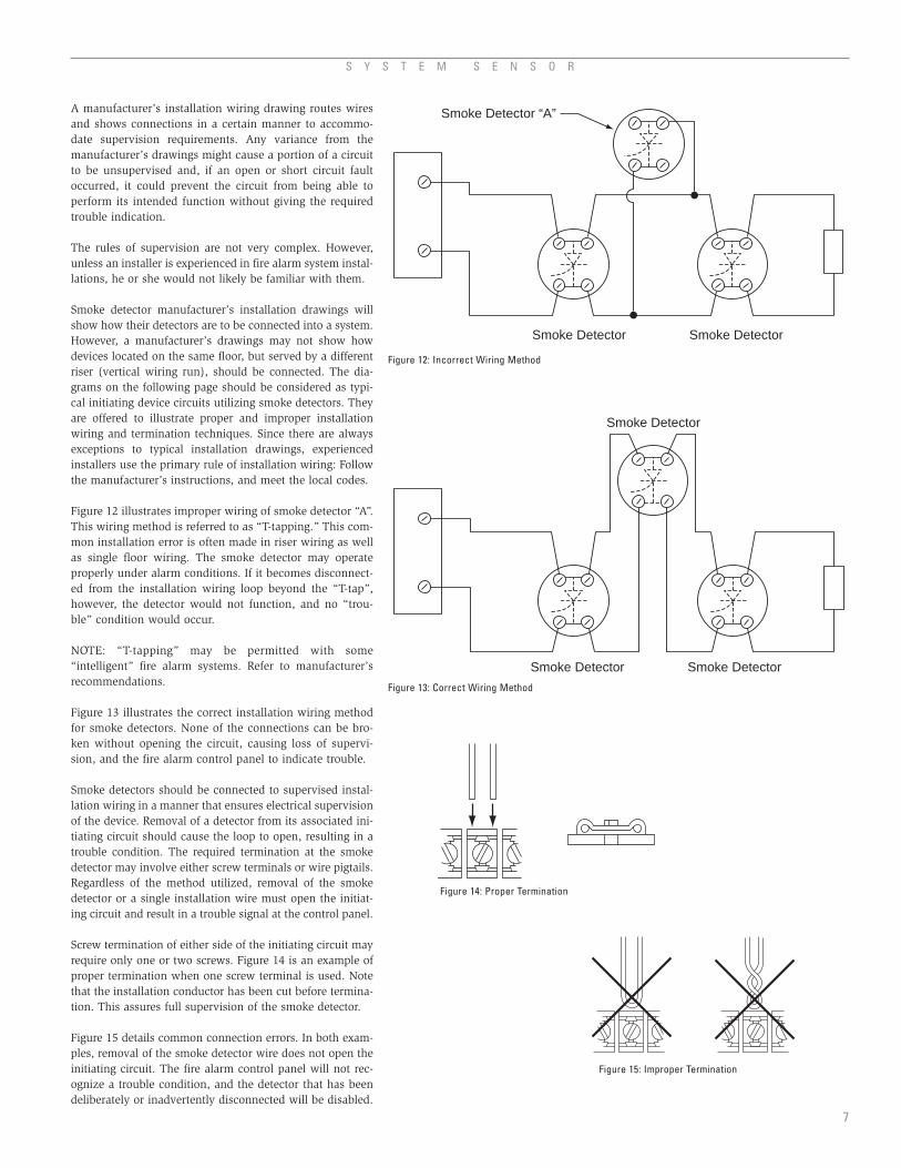
A manufacturer’s installation wiring drawing routes wiresand shows connections in a certain manner to accommo-date supervision requirements. Any variance from themanufacturer’s drawings might cause a portion of a circuitto be unsupervised and, if an open or short circuit faultoccurred, it could prevent the circuit from being able toperform its intended function without giving the requiredtrouble indication.
The rules of supervision are not very complex. However,unless an installer is experienced in fire alarm system instal-lations, he or she would not likely be familiar with them.
Smoke detector manufacturer’s installation drawings willshow how their detectors are to be connected into a system.However, a manufacturer’s drawings may not show howdevices located on the same floor, but served by a differentriser (vertical wiring run), should be connected. The dia-grams on the following page should be considered as typi-cal initiating device circuits utilizing smoke detectors. Theyare offered to illustrate proper and improper installationwiring and termination techniques. Since there are alwaysexceptions to typical installation drawings, experiencedinstallers use the primary rule of installation wiring: Followthe manufacturer’s instructions, and meet the local codes.
Figure 12 illustrates improper wiring of smoke detector “A”.This wiring method is referred to as “T-tapping.” This com-mon installation error is often made in riser wiring as wellas single floor wiring. The smoke detector may operateproperly under alarm conditions. If it becomes disconnect-ed from the installation wiring loop beyond the “T-tap”,however, the detector would not function, and no “trou-ble” condition would occur.
NOTE: “T-tapping” may be permitted with some “intelligent” fire alarm systems. Refer to manufacturer’srecommendations.
Figure 13 illustrates the correct installation wiring methodfor smoke detectors. None of the connections can be bro-ken without opening the circuit, causing loss of supervi-sion, and the fire alarm control panel to indicate trouble.
Smoke detectors should be connected to supervised instal-lation wiring in a manner that ensures electrical supervisionof the device. Removal of a detector from its associated ini-tiating circuit should cause the loop to open, resulting in atrouble condition. The required termination at the smokedetector may involve either screw terminals or wire pigtails.Regardless of the method utilized, removal of the smokedetector or a single installation wire must open the initiat-ing circuit and result in a trouble signal at the control panel.
Screw termination of either side of the initiating circuit mayrequire only one or two screws. Figure 14 is an example ofproper termination when one screw terminal is used. Notethat the installation conductor has been cut before termina-tion. This assures full supervision of the smoke detector.
Figure 15 details common connection errors. In both exam-ples, removal of the smoke detector wire does not open theinitiating circuit. The fire alarm control panel will not rec-ognize a trouble condition, and the detector that has beendeliberately or inadvertently disconnected will be disabled.
Smoke Detector “A”
Smoke Detector Smoke Detector
Smoke Detector
Smoke Detector
Smoke Detector
Figure 12: Incorrect Wiring Method
Figure 13: Correct Wiring Method
Figure 14: Proper Termination
Figure 15: Improper Termination

After all detectors have beeninstalled, test the completesystem to ensure that nowiring faults exist, and that allparts of the system operate asintended. A complete system
checkout consists of testing each detector at its installedlocation and following the panel manufacturer’s instruc-tions for system checkout. Also, refer to NFPA 72 for addi-tional information.
Where to Place DetectorsDetector placement is critical to early warning functions.To provide effective early warning of a developing fire sit-uation, smoke detectors should be installed in all areas ofthe protected premises. Total coverage as defined by NFPA72 should include all rooms, halls, storage areas, base-ments, attics, lofts, and spaces above suspended ceilingsincluding plenum areas utilized as part of the HVAC sys-tem. In addition, this should include all closets, elevatorshafts, enclosed stairways, dumbwaiter shafts, chutes andother subdivisions and accessible spaces.
Fire detection systems installed to meet local codes or ordi-nances may not be adequate for early warning of fire.
A P P L I C A T I O N S G U I D E : S Y S T E M S M O K E D E T E C T O R S
8
Figure 16 is an example of properly connectedsmoke detectors provided with pigtails. Thismethod of termination supervises all wiring tothe point at which it connects to the detector.
Figure 17 shows an incorrect pigtail connec-tion. This is a form of “T-tapping” discussedearlier. Note that the conductor between thewire nut (or splice) and the detector is unsu-pervised, and could be cut or disconnectedwithout resulting in a trouble signal.
Wireless SystemsWireless smoke detectors do not require anyfield wiring as the power for the initiatingdevices is contained and incorporated withinthe device. Removal of a wireless smoke detec-tor initiates a distinct tamper or trouble signal.Follow the instructions in the manufacturer’sinstallation manual for wireless systems.
Installation Do’s and Don’tsDo:
• Verify that 2-wire smoke detectors to beused have been tested and UL listed forcompatibility with the equipment towhich they are connected. If necessary,contact the manufacturer for this informa-tion.
• Locate any end-of-line devices electricallyat the end of the circuit, beyond all initi-ating devices (not at the control unit,except in a Class A installation).
• Use caution when utilizing 2-wire detec-tors with integral relays, because they
may require more power than the initiating device cir-cuit can supply. This could result in the inability of therelay to control auxiliary equipment to which it is con-nected.
• When using wireless detectors, follow the manufactur-er’s installation instructions to assure proper radiocommunication between the smoke detector and thecontrol panel.
• Observe polarity when required.• Protect detectors against contamination during con-
struction or renovation.• Carefully follow the manufacturer’s installation
instructions.
Don’t:• “T-tap” smoke detectors or circuit conductors, except
when specifically permitted by the manufacturer aspart of an intelligent/addressable system.
• Loop uncut installation conductors around screw ter-minations.
• Exceed the maximum resistance permitted for the ini-tiating device system.
• Exceed the number of 2-wire detectors allowed on a 2-wire initiating circuit (specified by UL).
Wiring and System CheckoutAs required for all installation wiring of fire alarm systems,check the detector loop wiring for grounds, short circuits,and open faults before the system is placed into operation.Each detector should be tested in accordance with themanufacturer’s instructions.
When using wireless detectors, verify the radio signal trans-mission strength in accordance with the installation manual.
Section 4
Proper DetectorApplications,Placement andSpacing*
*The guidelines in this section of the guide are adapted from Standards published by the National Fire Protection Association, Quincy,Massachusetts, USA. These standards include NFPA 72, National Fire Alarm Code; NFPA 70, “National Electrical Code”, Article 760; and NFPA90A, “Installation of Air Conditioning and Ventilating Systems”.
SmokeDetector
Wire Nut
Figure 16: Pigtail Connections –Correct Wiring Method
Figure 17: Pigtail Connections –Incorrect Wiring Method
Some codes or ordinances have minimum objectives suchas capturing elevators or preventing circulation of smokethrough the HVAC systems instead of early detection of fire.
A user should weigh the costs against the benefits ofinstalling a complete fire detection system when any detec-tion system is being installed. The location, quantity andzoning of detectors should be determined by what objec-tives are desired rather than the minimum requirements ofany local codes or ordinances.
“Total coverage”, as defined in NFPA 72, is the definitionof a complete fire detection system. In some of the speci-fied areas of coverage, such as attics, closets, under openloading docks or platforms, a heat detector may be moreappropriate than a smoke detector. Careful considerationshould be given to the detector manufacturer’s instructionsand the following recommendations in this guide.
In general, when only one detector is required in a room orspace, the detector should be placed as close to the centerof the ceiling as possible. Central location of the detector isbest for sensing fires in any part of the room. If a centerlocation is not possible, it may be placed no closer than 4inches from the wall, or if listed for wall mounting, it may
SmokeDetector
Wire Nut

S Y S T E M S E N S O R
be mounted on the wall. Wall-mounted detectors should belocated not less than 4 inches nor more than 12 inchesfrom the ceiling to the top of the detector, and at least 4inches (10 cm) from any corner wall junction. (See Figure18.)
When air supply and/or air return ducts are present in aroom or space, the detector(s) should not be placed in thepath of the air flow supply or return duct (NFPA 72, 1999Edition).
Smoke tests are helpful in determining proper placement.Special attention should be given to smoke travel directionsand velocity, since either can affect detector performance.
Placement of detectors near air conditioning or incomingair vents can also cause excessive accumulation of dustand dirt on the detectors. This dirt can cause detectors tomalfunction and cause unwanted alarms. Detectors shouldnot be located closer than 3 feet from an air supply diffuseror an air return vent.
Spot type detectors, in properly engineered systems, mayalso be placed in return air ducts, or in approved ductdetector housings designed for this application. Althoughduct detectors are not a substitute for open area detectors,they can provide an effective method of initiating buildingcontrol functions to prevent smoke from being transportedfrom the fire area to other parts of a building. (See DuctSmoke Detector Applications Guide.)
Ceiling
Acceptable HereNever Here
Top of Detector Acceptable Here
Side Wall
4 in. (10 cm)
4 in
. (10
cm
)M
inim
um
12 in
. (30
cm
)M
axim
um
Note: Measurements shown are to theclosest edge of the detector.
Figure 18: Wall Mounted Detector – Placement
Where Not To Place DetectorsSee Table A-2-3.6.1.2A in NFPA 72-1999.
One of the major causes of unwanted alarms is improperplacement of detectors. The best way to avoid unwantedalarms is not to install detectors in environments that cancause them to malfunction, or to install detectors speciallydesigned for those environments. Examples follow:
• Excessively Dusty or Dirty AreasIn excessively dusty or dirty areas consider using theFiltrex™ smoke detector. This detector incorporates amicroprocessor-controlled air intake fan and filter thatallows the unit to be installed in areas where ordinarydetectors cannot be used. Filtrex is an intelligentsmoke detector that removes airborne particles beforethey reach the sensing chamber. It is ideal for textilemills, dusty manufacturing facilities, paper mills, andrecycling centers. For more information see SystemSensor’s Filtrex™ Applications Guide.
• OutdoorsAvoid using detectors outdoors, in open storage sheds,or other open structures affected by dust, air currents,or excessive humidity and temperature extremes.
• Wet or Excessively Humid AreasAvoid damp, wet or excessively humid areas, or nextto bathrooms with showers.
• Elevator LobbiesDo not place over ashtrays or where people will smokewhile waiting for the elevator.
• Extreme Cold or Hot EnvironmentsAvoid very cold or very hot environments, or unheat-ed buildings or rooms where the temperature can fallbelow or exceed the operating temperature range ofthe detector. At temperatures above or below the oper-ating range of the detector*, its internal componentsmay not function properly.*Manufacturers’ specifications should list acceptabletemperatures in these ranges.
• Areas with Combustion Particles Avoid areas where particles of combustion are nor-mally present, such as in kitchens or other areas withovens and burners; in garages, where particles of com-bustion are present in vehicle exhausts. When a detec-tor must be located in or adjacent to such an area, aheat detector may be appropriate.
• Manufacturing AreasAvoid manufacturing areas, battery rooms, or otherareas where substantial quantities of vapors, gases, orfumes may be present. Strong vapors can make detec-tors overly sensitive or less sensitive than normal. Invery large concentrations, gases heavier than air, suchas carbon dioxide, may make detectors more sensitive,while gases lighter than air, such as helium, may makethem less sensitive. Aerosol particles may collect ondetector chamber surfaces and cause nuisance alarms.
• Fluorescent Light FixturesAvoid placement near fluorescent light fixtures.Electrical noise generated by fluorescent light fixturesmay cause unwanted alarms. Install detectors at least1 foot (0.3 m) away from such light fixtures.
9

A P P L I C A T I O N S G U I D E : S Y S T E M S M O K E D E T E C T O R S
Special Application DetectorsThe guidelines in this document generally apply to stan-dard open-area smoke detectors. System Sensor has a num-ber of advanced technology detectors that are optimizedfor specific environments and should be considered.
Pinnacle™ Laser technology smoke detector is designed foruse in areas that require extremely early warning of fire. Itis designed to detect the earliest particles of combustionmaking it ideal for clean rooms, computer rooms ortelecommunication centers — any area where any damageis too much. As Pinnacle is ultra-sensitive to smoke — asmuch as 100 times more sensitive than standard detectors— care and judgement of application is needed to preventunwanted alarms. See System Sensor’s Pinnacle™
Applications Guide.
For environments classified as hazardous, System Sensoroffers Intrinsically Safe Detectors designed to providedetection for high-risk areas such as oil production facili-ties, refineries and chemical plants. These units operate onlow energy levels and are used with a safety barrier. Seeour Guide for Proper Use of Intrinsically Safe FireProtection Devices.
Standards for Smoke DetectorsUnderwriters Laboratories (UL) has three standards forsmoke detectors: one for duct detectors, UL 268A; one forsingle and multiple station smoke alarms, UL 217; and onefor systems type detectors, UL 268. Detectors should onlybe used for the applications for which they are specificallylisted.
The 2000 NFPA 101 Life Safety Code notes in Section9.6.2.10.4 that single station smoke alarms shall sound analarm only within an individual living unit, suite of rooms,or similar area and shall not actuate the building fire alarmsystem unless otherwise permitted by the authority havingjurisdiction. Section 9.6.1.5 states, “All systems and com-ponents shall be approved for the purpose for whichinstalled.”
In addition to possible code noncompliance, the followingdeficiencies would exist in a series of residential smokedetectors, connected in a system mode:
• Since the system is not supervised, vandals or otherscould disconnect a detector or the entire system, leav-ing a building without protection. The residents wouldbe unaware of this serious life threatening condition.
• Residential smoke alarms do not latch in alarm. Inother words, the smoke alarm self-resets. One smokealarm in alarm will sound all the smoke alarms con-nected together. It would be difficult to identify orlocate a specific smoke alarm that initially put the sys-tem into alarm after the alarm condition was cleared.
System detectors latch in alarm. They do not reset untilpower is momentarily disconnected. This makes it conven-ient to identify the location of a detector that caused thecontrol panel to alarm. In addition, system detectors arespecifically designed to connect to a panel. Two-wire detec-tors require a UL compatibility review to verify that thedetector and panel operate together. A typical life safetyfire protection system for an apartment complex would be
to use system detectors and manual fire alarm stations inthe hallways and common areas of the complex and resi-dential single station type smoke detectors and heat detec-tors in the individual apartments. The system detectors,manual stations and heat detectors would be connected toa control panel, sound a general alarm and automaticallynotify the proper authorities that a fire condition exists.The residential smoke detectors located in the apartmentswould be interconnected only within the individual livingquarters of each apartment. These residential units wouldsound an alarm only in the apartment where a fire started.
Detector SpacingGeneral Spacing GuidelinesSome fire protection codes specify detector spacing on agiven center-to-center distance between detectors underideal conditions. These distances are based on rooms withsmooth ceilings with no physical obstructions between thecontents being protected and the detectors. Moreover, theyare also based on a maximum ceiling height, and on theassumption that the value and the combustible nature ofthe contents of the room to be protected do not warrantgreater protection or closer spacing.
If we assume a typical center distance spacing guideline is30 feet (90 meters), how do we determine whether a givenroom or space can be protected by a single detector? Figure19 shows four detectors spaced horizontally and vertically30 feet (9 meters) apart. Detectors B and D, however, aremore than 30 feet apart. Clearly, in this example detectorspacing can exceed the given 30 foot spacing and still com-ply with the code if any source of combustion is within21.2 feet (6.4 meters) of the horizontal projection of adetector, and if no more than 900 square feet (82.8 squaremeters) are being protected by one detector.
To determine what coverage patterns are permissible with-in the 30 foot spacing, start by tracing a circle with a radiusof 21.2 feet. Keeping in mind the fact that most rooms andareas to be protected are rectangular or square in shape, anysquare or rectangle that fits within the circumference of thecircle may be protected by one detector. (See Figure 20.)
10
30 ft. (9.1 m)
21.2
ft. (
6.4
m)
30 ft
. (9.
1 m
)
A
F
B
CD
Figure 19: Typical Detector Spacing

S Y S T E M S E N S O R
In other words, if a diagonal through the center of the roomis no greater than the diameter of the circle, or 42.4 feet(12.8 meters), one detector can be used under ideal condi-tions. Figure 21 shows how a length of hallway can be pro-tected by only two detectors under ideal conditions.
Special Spacing ProblemsThe ideal conditions upon which code guidelines are baseddo not exist in the majority of buildings. Detector installersusually have to deal with a variety of problems, such asuneven ceilings or ceilings crossed by beams and joists;storage racks and partitions that obstruct the path of smoketoward detectors; air stratification due to uninsulated roofs,peaked or sloped ceilings, or localized heating or coolingfrom heating, ventilating, and air conditioning systems;and extensive variability in the value and combustion char-acteristics of building contents. The following are suggest-ed techniques for dealing with some of the special detectorspacing problems:
• Solid joist and beam construction. Per NFPA 72-1996,solid joists are to be considered equivalent to beamsfor smoke detector spacing guidelines. For ceilingheights of 12 ft. (3.66 m) or lower and beam depths of1 ft. (0.3 m) or less, smooth ceiling spacing running inthe direction parallel to the run of the beams is to beused, and 1/2 the smooth ceiling spacing is to be usedin the direction perpendicular to the run of the beams.Spot-type detectors may be located either on the ceil-ing or on the bottom of the beams. For beam depthsexceeding 1 ft. (0.3 m) or for ceiling heights exceeding12 ft. (3.66 m), detectors are to be located on the ceil-ing in every beam pocket. If the beamed ceiling is alsosloped, use the spacing determined for flat beamedceilings. Use the average height over the slope as theceiling height in such cases. Note that, by definition inNFPA 72, ceilings are to be considered smooth unlessthe beams or joists are more than 4 in. (0.1 m) indepth.
• High storage racks. Multi-level storage racks presentspecial problems for early fire detection. Developingfires, especially smoldering fires, on the lower levels ofthe racks may not be sensed rapidly by ceiling mount-ed detectors. Upward convection of smoke can beslowed or blocked by goods stored on the upper levelsof the racks. Multi-level fire detection is required.Detectors should be installed on the ceiling above eachaisle and on intermediate levels of the racks adjacentto alternate pallet sections, shown in NFPA 72-1999,A-2-3.6.5. A consultant’s judgement may be requiredfor specific installations.
• Partitions. Partitions and many types of large, tallequipment standing on the floor can block the flow ofsmoke toward detectors. Any partition or similarobstruction that is less than 18 inches (45 cm) fromthe ceiling should be treated as a side wall dividing thearea protected.
• Air Stratification. Air stratification in a room may keepair containing smoke from reaching ceiling-mounteddetectors. Three conditions are known to accentuateair stratification: when a layer of hot air exists under apoorly insulated roof heated by the sun, cooler air willstratify the hot air layer at the ceiling; when a layer ofcold air exists under a poorly insulated roof cooledfrom the outside by cold air, the heated air is cooled asit reaches the cold air layer; or when a heating, venti-
lating, or air conditioning (HVAC) system creates arti-ficial hot or cold air layers in a room, the layers mayaffect the flow of smoke to the detectors.
• Uninsulated Roofs. Uninsulated roofs present specialplacement problems. Air movement toward ceilingdetectors is not impeded when the outside tempera-ture is cool, but stratification can occur when outsidetemperature is warm or hot, or when the roof is heat-ed by the sun on bright, sunny days. Although truethermal barriers are not present in many installations,smoke tests should be run in factories or warehouseswith metal roofs on warm sunny days to determinewhether such a thermal barrier exists.
• Peaked or Sloped Ceilings. Peaked or sloped ceilingscan foster air stratification. Codes may specify spacingdetectors by using horizontal spacing from the peak ofthe roof or ceiling. For instance, if the specified dis-tance from the peak is 3 feet (1 m), the dis-tance is measured on the base of theright triangle formed by a vertical linedropped from the peak of the roof,with the roof incline as thehypotenuse. Additional detec-tors are installed on theselected spacing, usingthe horizontal distance,not the distancealong the incline ofthe ceiling. (SeeFigure 22.)
Rectangles
A 10 ft. × 41 ft. = 410 sq. ft.
B 15 ft. × 39 ft. = 585 sq. ft.
C 20 ft. × 37 ft. = 740 sq. ft.
D 25 ft. × 34 ft. = 850 sq. ft.
E 30 ft. × 30 ft. = 900 sq. ft.
21 ft.21 ft. 21 ft.21 ft.
41 ft.20.5 ft. 20.5 ft.
82 ft.
10 ft.
Figure 20: Detector Coverage Patterns
Figure 21: Detector Placement in Hallways
Detector may be placedanywhere in shaded area.
S = Detector Spacing
S/2 S S
3 ft. 3 ft.
S/2
Figure 22: Detector Spacing Layout – Sloped Ceilings (peaked type)
11

A P P L I C A T I O N S G U I D E : S Y S T E M S M O K E D E T E C T O R S
12
• Alternate Detector Mounting. Mounting alternatedetectors up to 3 feet (1 m) below the ceiling canincrease detection of small or smoldering fires whenthe possibility of air stratification exists. Figure 23illustrates such an installation. Specific designs forsuch an alternate detection should be based upon anengineering survey.
• Heating, Ventilating and Air Conditioning (HVAC)effects on air flow and air stratification should bedetermined and considered when planning detectorplacement. In rooms where forced-air ventilation ispresent, detectors should not be located where airfrom supply diffusers could dilute smoke before itreaches the detector. This may require additionaldetectors, because placing detectors only near returnair openings may leave the balance of the area withinadequate protection, especially when the Heating,Ventilating and Air Conditioning (HVAC) system is notoperating.
• Detectors placed in an above-ceiling air handling spaceshould not be used as a substitute for open area pro-tection, because smoke may not be drawn into the airhandling space when the ventilating system is shutdown. The detector will be less responsive to a firecondition in the room below than a detector located onthe ceiling of the room below due to dilution and fil-tering of the air in the air handling space before thesmoke reaches a detector. (See the discussion of detec-tor placement in Section 4: Where To Place Detectors).
• Burn characteristics and the value of assets being pro-tected influence the spacing of detectors and theamount of protection provided in a specific room orarea. Refer to NFPA 72-1999, Section 2-3.6 for moredetailed information on spacing of detectors underspecial applications. Likewise, if the contents are espe-cially valuable, for example, sophisticated and expen-sive machinery or irreplaceable records, detectorsshould be placed closer together.
Detectors in Air Handling and Air ConditioningSystemsSee NEMA Guide for Proper Use of Smoke Detectors inDuct Applications and NFPA 72, National Fire Alarm Codefor more specific information.
Detectors in Above-Ceiling Plenum AreasIncluding Plenums Utilized as Part of the HVACSystem Detectors should be placed in plenum areas (above ceilingair handling space) in addition to the open area detectorsinstalled in the open areas below and duct detectorsinstalled in the ducts. Plenum detectors are required to belisted or tested and approved for the air velocities withinthe environment in which they are to be installed.
Detectors placed in plenums MAY NOT be used as a sub-stitute for open area protection, because smoke may not bedrawn into the plenum when the ventilating system is shutdown. When the system is operating, the detector may beless responsive to a fire condition in the room below thanwill a detector located on the ceiling of the room below.This may be due to blockage, dilution, and filtering of theair prior to its arrival at the detector location in the plenumarea.
Since the air circulating through the plenums is usually athigher velocities than would be prevalent in the roombelow, detector spacing should be reduced.
Also, the dilution of the smoke in plenum spaces is animportant consideration when utilizing smoke detectorsrated for higher velocities. Therefore, plenum detectorsshould be utilized to detect fire in the plenum but shouldnever be utilized as a substitute for duct detectors andopen area detectors.
Maintenance requirements of detectors exposed to unusu-al velocities (above 300 fpm) are generally increased due tothe excessive dirt buildup and contamination present inthese environments.
Figure 23: High Ceiling Area
A A
3 ft. Minimum
Smoke Detectors at Ceiling
Smoke Detectors below Ceiling

S Y S T E M S E N S O R
13
Smoke detectors are designedto be as maintenance free aspossible. However, dust, dirt,and other foreign matter canaccumulate inside a detector’ssensing elements and changeits sensitivity. They can
become either more sensitive, which may cause unwantedalarms, or less sensitive, which could reduce the amount ofwarning time given in case of a fire. Both are undesirable.Therefore, detectors should be tested periodically andmaintained at regular intervals. Follow closely the manu-facturer’s specific recommended practices for maintenanceand testing. Also refer to Appendix B of NFPA 90A andNFPA 72, Chapter 7.
Typical Inspection, Test and MaintenancePracticesDetectors should be given a visual inspection at installationand at least twice a year thereafter. This ensures that eachdetector remains in good physical condition and that thereare no changes that would affect detector performance,such as building modifications, occupancy hazards, andenvironmental effects.
Notify the proper authorities that the smoke detector isundergoing maintenance, and therefore the system willtemporarily be out of service. NOTE: Disable the zone orsystem undergoing maintenance to prevent unwantedalarms and possible dispatch of the fire department.
Use a high power vacuum cleaner and remove dust fromthe detector by placing the nozzle as close as possible tothe openings in the outside housing. A nozzle with a brushattachment will assist in dust removal. Some detector’ssensing chambers can be removed for more thoroughcleaning; refer to the manufacturer’s recommended proce-dure for details.
Test each detector’s sensitivity per the manufacturer’s rec-ommended procedure within one year after installationand every alternate year thereafter.
Test each detector functionally in place annually, asdetailed in NFPA 72 1999 (Chapter 7).
If a detector’s sensitivity is within specifications, nothingfurther needs to be done to the detector. If the detector’ssensitivity is outside specifications, clean the detector andretest. If that does not place the sensitivity within the unitspecified range then follow the manufacturer’s recom-mended procedure.
Restore zone or system at the completion of testing.
Notify the proper authorities that testing has been com-pleted and the system is again operational.
Refer to paragraph 7-4.1 of NFPA 72 for additional infor-mation.
To assure that each smoke detector is within its listed andmarked sensitivity range it should be tested using either:
• A calibrated test method, or• The manufacturer’s calibrated sensitivity test instru-
ment, or• Listed control equipment arranged for the purpose, or• Other calibrated sensitivity test method acceptable to
the authority having jurisdiction.
Detectors found to have a sensitivity of 0.25 percent/ft.obscuration or more outside the listed and marked sensi-tivity range should be cleaned and recalibrated or replaced.Exception: Detectors listed as field adjustable may beeither adjusted within the listed and marked sensitivityrange, cleaned and recalibrated, or replaced.
Restore the zone or system at the completion of testing.
Notify all the persons contacted at the beginning of the testthat testing has been completed and the system is againoperational.
Some individuals rely on an aerosol chemical spray to testthe sensitivity of a detector. This can give unsatisfactoryresults since an aerosol chemical spray does not accurate-ly test detector sensitivity. NFPA 72-1999, Chapter 7,Section 7-3.2.1 notes that, “The detector sensitivity shallnot be tested or measured using any device that adminis-ters an unmeasured concentration of smoke or otheraerosol into the detector.” The duration of spray, distancebetween the detector and the aerosol container, angle ofdischarge, and different environmental conditions can pro-duce random results. In addition, many aerosols leave anoily residue. Over a period of time, this oily residue canattract dust or dirt, which can make a detector more sensi-tive and result in nuisance alarms.
Be sure to follow the manufacturer’s recommendation ontest gas, aerosol or smoke.
Section 5
Testing,Maintenance and Service ofDetectors
CautionSmoke detectors are sophisticated electronic devices thatneed periodic testing and maintenance. To maintain theintegrity of any fire alarm system, it is important to have aqualified person periodically test the system.
14
A P P L I C A T I O N S G U I D E : S Y S T E M S M O K E D E T E C T O R S
What to Do AboutUnwanted AlarmsNo detection system is imper-vious to unwanted alarms.
Statistically, as the system size and the total number ofdetectors increases, the total number of nuisance alarmsper year tends to increase. Historical experience in a giveninstallation or data on similar sized buildings with similarutilization patterns can provide a basis for a rough indica-tion of how many nuisance alarms are probable during a12 month span; however, no two installations are identical.
In small- to moderate-sized detection systems protectingrelatively combustion-free environments, like office build-ings, more than one or two unwanted alarms per yearwould be unusual. In more adverse environments, such aslaboratory or manufacturing facilities where combustionprocesses are present, more frequent alarms can be antici-pated. In very adverse environments, one alarm per monthmight not be considered excessive.
After the first few months, which serve as a shakedownperiod, it should be possible to arrive at some reasonableexpectation for probable unwanted alarms from the sys-tem. After that, any unexpected change in frequency or dis-tribution indicates a problem that should be investigated.The best way to monitor alarm frequency and distributionis to maintain an alarm log.
Reasons for Unwanted AlarmsUnwanted alarms can result from a wide variety of causes,including:
• Improper locations are environments where they willnot operate properly because of temperature extremes;excessive dust, dirt, or humidity, excessive air flowrates, or the normal presence of combustion particlesin the air streams surrounding the detectors.
• Improper installation can occur when detectors andtheir wiring are not protected from interference frominduced currents and noise in adjacent wiring systems,radio-frequency transmissions, and other types of elec-tromagnetic effects.
• Inadequate maintenance can result in the accumula-tion of dust and dirt on the detector’s sensing cham-bers over a period of time.
• Seasonal effects such as the reactivation of a buildingheating system after an extended summer shutdowncan cause alarms.
• Building maintenance issues, such as accidental trig-gering of a detector’s magnetic test switch, or theintroduction of plaster dust from drywall repairs into adetector’s sensing chamber can cause unwantedalarms.
• Induced current effects from lightning storms cancause alarms.
• Infestation from insects small enough to enter thedetector’s sensing chamber.
• Vandalism or mischievous acts — detectors set off as aprank have been found to be a problem in dormitories.
If an alarm occurs and a fire does not exist, the alarmshould be silenced, the problem unit located, and thealarm system controls reset so that the effectiveness of thedetection system is restored.
Make sure that all the detectors in the zone or pinpointeddevice(s) that show an alarm are checked before decidingthat it is a false alarm. If a fire does exist, more than onedetector may be in the alarm state, although no signs of firemay be evident in the vicinity of the first activated detec-tor. The fire could be overlooked.
Maintain an Alarm LogThe next step for all alarms should be entry of a report intoan Alarm Log. A typical Alarm Log is shown in Appendix2 (page 19). Such a log serves immediate and long-termpurposes.
The Alarm Log indicates which individuals responded tothe alarm and whether or not they took appropriate action.
Periodic review of the cumulative Alarm Log can help thoseresponsible for the detection system discern patterns in thereported alarms. Generally, several months (or even years)of data may be necessary before patterns begin to emerge.
In a worst case example, a pattern of repeated alarms orsmall fires in a particular area may indicate a serious defi-ciency in safety practices that should be promptly correct-ed. In less obvious cases, patterns are indicated by repeat-ed alarms in the same or adjacent zones with similar prob-able causes, or repeated alarms in the same zone thatoccur at about the same time of day, or time of year.
Effects of Location or EnvironmentCheck for the effects of location and environment. Reviewthe information in this guide Where To Place Detectors andWhere NOT to Place Detectors to determine whether thedetector’s location or its environment is potentially causingthe unwanted alarms. Also, refer to the installation manu-al for further information.
One often overlooked source of problems is the placementof detectors where air streams carry smoke or chemicalfumes from some areas of an installation past detectors inother areas unrelated to the source of the contaminants.Diagnosing problems of this kind requires that air move-ments into the problem area, especially near the ceiling, becarefully checked and their sources be determined.Experienced heating, ventilating, and air conditioning(HVAC) engineers or contractors usually have the trainingand specialized equipment (flow meters, etc.) to conductsuch a study. In very difficult cases, a full-scale smoke testmay be required to solve the problem.
Conversely, strong air streams near air inlet or supplyducts, etc. can also prevent a detector from signaling analarm when a fire is present by blowing smoke away fromthe detector heads.
Inspect Detector for Dirt and Review MaintenanceIf the Alarm Log indicated that after several months or ayear with a fairly stable alarm rate, there is a gradualincrease in the frequency of unwanted alarms, this is usu-ally an indication that the detectors in the system shouldbe cleaned.
Section 6
TroubleshootingTechniques

S Y S T E M S E N S O R
15
NFPA standards require and smoke detector manufacturersrecommend that all detectors be visually inspected twice a year.
Clean the detectors at least once a year, or more frequent-ly if environmental conditions warrant it. See the sectionon Detector Testing and Maintenance in this guide for moredetails.
In cases where the probable cause of a number of alarmsappears to be dust or dirt on the detectors, detector main-tenance schedules should be reviewed to determine thedates when the detectors were last cleaned and tested. Ifthe detectors are due or overdue for maintenance, schedul-ing and performing the recommended cleaning and testingshould eliminate the problem.
If the problem resulted from a temporary overall increasein airborne dust due to nearby construction, scheduling aone-time special cleaning for all the detectors in the systemshould alleviate the problem. If the problem is confined toone or two zones and is the result of higher dust levels ina particular area, scheduling the detectors in those areasfor more frequent maintenance and cleaning may preventthe development of similar alarm problems in the future.
Effects of Other Systems on Alarm SystemIn checking for the effects of other systems on the alarmsystem wiring the Alarm Log may be very valuable in help-ing to pinpoint relationships among apparently causelessalarms. One important fact that can be obtained from anAlarm Log is the beginning date for a rash of apparentlycauseless alarms that may or may not be grouped aroundone particular zone. The sudden onset of such a group ofalarms may result when an addition or change in the alarmsystem or in another electrical or electromechanical systemin the building affects the detectors or the alarm systemcircuitry.
Systems that can affect the alarm system include: othersecurity systems; walkie-talkie; mobile telephones; heat-ing, ventilating, and air conditioning controls; elevator callsystems; remote control equipment (door closers, etc.);and even the installation of microwave antenna. If thealarm pattern supports the possibility of some kind ofinterference with a fairly definite initiation date, all equip-ment changes made in the building immediately prior to orconcurrent with the beginning of the development of thealarm pattern should be reviewed. In addition, the wiringlayouts of the alarm system and any recent building or sys-tem modifications should be compared to make sure thatthe spacing and/or shielding required to protect the alarmsystem wiring from other potentially interfering electricalsystems was maintained.
Miscellaneous Causes of Unwanted AlarmsIsolated alarm causes such as a maintenance person acci-dentally triggering an alarm by touching a detector with amagnetic screwdriver can be ignored, except to periodical-ly remind maintenance personnel to be careful when work-ing around detectors.
Steps should also be taken to protect detectors from dustwhenever maintenance requires sawing, sanding, drilling,
or other dust-producing operations in the vicinity of thedetector heads to prevent false alarms due to the dust get-ting into the detector sensing chambers. In new construc-tion applications drywall dust contamination affects alltypes of smoke detectors. To help overcome this problem, itis strongly recommended that installation of detector headsbe delayed until after drywall installation is completed or toprotect detector heads from dust contamination.
If alarms occur whenever the heating system is turned onafter an extended shutdown, due to the accumulated dustburning off as the system components heat, the detectorsystem can be turned off for a short period while the heat-ing system is activated and checked out, or the start-up ofthe heating system can be scheduled for an evening, week-end or other off-hours period to minimize the effects ofalarms on regular daytime activities.
Not all unwanted alarms are caused by dirt, interference orother effects on the detectors. If the control panel shows analarm but no detectors in the zone are indicating an alarmcondition, the possibility of interference or a failure of acontrol panel component should also be investigated.
Responsibilities of Detector Owners andInstallersThe owners of smoke detector-equipped fire alarm systemsare responsible for maintaining the integrity of the detec-tion system. This can be accomplished by:
• Maintaining an Alarm Log and training appropriatepersonnel to properly maintain the system asdescribed above in the section titled What To Do WhenUnwanted Alarms Occur.
• Maintaining a Detector Maintenance Log that recordsinspection, testing and cleaning data for each detectorin the system. (Refer to Section 6 of this manual –Testing, Maintenance and Service of Detectors forinformation on recommended testing and maintenanceintervals and procedures, and a sample DetectorMaintenance Log page.)
• Maintaining a complete file of information on thealarm system in a readily accessible location. This fileshould include specifications and installation instruc-tions for the detectors, control panel, and auxiliarydevices, wiring diagrams and wire location informa-tion, and the manufacturer’s recommendations for iso-lating the detection system wiring from other electricalwiring to prevent interference and unwanted alarms.
• Making certain that maintenance personnel or con-tractors working on the building’s electrical systemsare given copies of the alarm system wiring layout andlocations so that potential interference from otherwiring systems can be prevented by proper insulationand spacing during installation.
• Keeping accurate records of installation and modifica-tions to all other building electromechanical systemsthat could cause interference with the alarm system,including updating schematics, wiring layouts, andwiring location information whenever changes aremade, so that problems can be promptly found andeliminated.
• Making a record of everything done during investiga-tion of a series of alarms, indicating a problem exists.

A P P L I C A T I O N S G U I D E : S Y S T E M S M O K E D E T E C T O R S
16
If assistance must be sought from the installer or man-ufacturer, there will be an indication of the tests thathave already been done by the owner’s personnel.
These services can be provided by qualified outside organizations.
The installers of smoke detector equipped alarm systemsare responsible for providing the owners with the neces-sary information and training so that their personnel canmaintain the integrity of the alarm system. These respon-sibilities should include:
• Providing copies of the specifications and installationinstructions for the detectors, control panel, and auxil-iary devices; wiring diagrams and wire location infor-mation; and the manufacturer’s recommendations forisolating the detection system wiring from other elec-trical wiring to prevent interference and unwantedalarms.
• Verifying that the alarm system installation meets allapplicable code requirements.
• Completely testing a newly installed, expanded, ormodified alarm system to ensure that all componentsare working properly.
• Providing troubleshooting assistance to the owners fora specified break-in period after installation in caseproblems develop.
• Helping the owner set up appropriate DetectorMaintenance and Alarm Logs for the system.
• Providing initial instruction and training to theowner’s personnel or outside organization which willbe monitoring and maintaining the system.
• Providing troubleshooting assistance if nuisance alarmproblems cannot be solved satisfactorily by theowner’s personnel or outside organization.
Where to Get Help if the Source of UnwantedAlarms Can’t be FoundIn the event a series of unexplained unwanted alarmsand/or a review of the Alarm Log indicates that a problemsituation exists, the owner should conduct the initial inves-tigation to find a solution. If the owner’s personnel areunable to determine the cause for the alarms, the installeror representative of the manufacturer should be contactedto help pinpoint the problem.
Manufacturers can be contacted by phone for additionalsuggestions. If factory assistance is needed, a factory engi-neer may be able to explain the source of the problem withdata from your Alarm Log, complete description of youralarm system including detector model numbers, make andmodel number of the control panel and other components,and a complete summary of all aspects of the problem thathave already been checked.

S Y S T E M S E N S O R
Addressable System SmokeDetectorSystem smoke detectors,
which, in addition to providing alarm and trouble indica-tions to a control unit, are capable of communicating aunique identification (address).
Air Sampling-type DetectorA sampling-type detector consists of piping or tubing distri-bution from the detector unit to the area(s) to be protected.An air pump draws air from the protected area back to thedetector through the air sampling ports and piping or tub-ing. At the detector, the air is analyzed for fire particulate.
Alarm (Signal) Notification ApplianceAn electromechanical appliance that converts energy intoaudible or visible signal for perception as an alarm signal.
Alarm SignalA signal indicating an emergency requiring immediateaction, such as an alarm for fire from a manual box, awaterflow alarm, or an alarm from an automatic fire alarmsystem, or other emergency signal.
Alarm Verification FeatureA feature of automatic fire detection and alarm systems toreduce unwanted alarms, wherein automatic fire detectorsmust report alarm conditions for a minimum period of timeor confirm alarm conditions within a given time period,after being reset, to be accepted as a valid alarm initiationsignal.
AnnunciationA visible and/or audible indication of system status.
Automatic Fire Alarm SystemA system of controls, initiating devices and alarm signals inwhich all or some of the initiating circuits are activated byautomatic devices such as smoke detectors.
Class A Circuit (Loop)An arrangement of supervised initiating device, signalingline, or indicating appliance circuits that prevents a singleopen or ground on the installation wiring of these circuitsfrom causing loss of the system’s intended function.
Class B Circuit (Loop)An arrangement of supervised initiating device, signalingline, or indicating appliance circuits, which does not pre-vent a single open or ground on the installation wiring ofthese circuits from causing loss of the system’s intendedfunction.
Combination Smoke DetectorA smoke detector that combines two or more smoke or firesensing technologies.
Detector CoverageThe recommended maximum distance between adjacentdetectors or the area that a detector is designated to protect.
Drift CompensationThe capability of a detector to automatically adjust itsalarm sensitivity to compensate for any changes over timein the factory settings for smoke and/or fire detection. Inanalog systems, this may be done by the panel.
End of LineA device such as a resistor or diode placed at the end of aClass B wire loop to maintain supervision.
Appendix 1
Glossary of TermsEnd of Line RelayDevice used to supervise power (for four-wire smokedetectors) and installed after the last device on the loop.
False AlarmsAn unwanted alarm caused by non-smoke contaminantssuch as dust or insects.
FireA chemical reaction between oxygen and a combustiblematerial where rapid oxidation results in the release ofheat, light, flame and/or smoke.
Flame DetectorA device that detects the infrared, ultraviolet, or visibleradiation produced by a fire.
Four-wire Smoke DetectorA smoke detector which initiates an alarm condition ontwo separate wires (initiating loop) apart from the twopower leads.
Heat DetectorA device that detects abnormally high temperature or rate-of-temperature rise.
Initiating CircuitA circuit which transmits an alarm signal initiated manu-ally or automatically, such as a fire alarm box, smoke, heat,or flame sensing device, sprinkler waterflow alarm switchor similar device or equipment to a control panel or anysimilar device or equipment which, when activated, caus-es an alarm to be indicated or retransmitted. An InitiatingDevice Circuit (Loop) is a circuit to which automatic ormanual signal initiating devices are connected where thesignal received does not identify the individual deviceoperated.
Initiating DeviceAny manually operated or automatically operated equip-ment which, when activated, initiates an alarm through analarm signaling device.
Intelligent (Analog, Smart) System Smoke DetectorA system smoke detector capable of communicating infor-mation about smoke conditions at its location to a controlunit. This type of detector typically communicates aunique identification (address) along with an analog (data)signal, which indicates the level of smoke at its location.
Ionization Smoke DetectorAn ionization smoke detector has a small amount ofradioactive material that ionizes the air in the sensingchamber, thus rendering it conductive and permitting acurrent to flow between two charged electrodes. This givesthe sensing chamber an effective electrical conductance.When particles of combustion enter the ionization area,they decrease the conductance of the air by attachingthemselves to the ions, causing a reduction in mobility.When the conductance is less than a predetermined level,the detector responds in a fire alarm condition.
Light ScatteringThe action of light being reflected and/or refracted bysmoke particles for detection by a photoelectric smokedetector. The action of light being refracted or reflected.
ListedEquipment or materials included in a list published by anorganization (e.g., Underwriters Laboratories) acceptableto the “authority having jurisdiction” and concerned with
17

A P P L I C A T I O N S G U I D E : S Y S T E M S M O K E D E T E C T O R S
18
product evaluation, that maintains periodic inspection oflisted equipment or materials and whose listing stateseither that the equipment or material meets appropriatestandards or has been tested and found suitable for use ina specified manner.
Note: The means for identifying listed equipment may varyfor each organization concerned with product evaluation,some of which do not recognize equipment as listed unlessit is also labeled.
Maintenance ConditionMethod of providing annunciation of a smoke detector thatit is out of its listed sensitivity range.
National Fire Protection Association (NFPA) An organization that administers the development andpublishing of codes, standards, and other materials con-cerning all phases of fire safety.
Nuisance AlarmAn unwanted alarm caused by smoke from cooking or cig-arettes.
ObscurationA reduction in the atmospheric transparency caused bysmoke usually expressed in percent per foot.
Particles of CombustionSubstances (products that either remain at the site of burn-ing such as ash, or scatter as volatile products) resultingfrom the chemical process of a fire.
Photoelectric Smoke DetectorIn a photoelectric light scattering smoke detector, a lightsource and a photosensitive sensor are so arranged that therays from the light source do not normally fall on the pho-tosensitive sensor. When smoke particles enter the lightpath, some of the light is scattered by reflection and refrac-tion onto the sensor, causing the detector to respond.
Projected Beam Smoke DetectorIn a projected beam detector the amount of light transmit-ted between a light source and a photosensitive sensor ismonitored. When smoke particles are introduced into thelight path, some of the light is scattered and someabsorbed, thereby reducing the light reaching the receiver,causing the detector to respond.
Rate-of-rise Heat DetectorA device which will respond when the temperature rises ata rate exceeding a predetermined amount, usually 15° perminute.
Remote Maintenance ConditionNFPA 72 listed method of providing annunciation at thecontrol unit that the smoke detector is outside of its listedsensitivity.
Smoke DetectorA device that detects the visible or invisible particles ofcombustion.
Smoothing AlgorithmsA method of “smoothing out” a detector’s interpretation ofsudden, short-duration increases in obscuration within thesensing chamber, intended to reduce the occurrence of nui-sance alarms.
Spot (Point) DetectorA device whose detecting element is concentrated at a par-ticular location. Typical examples are bimetallic detectors,fusible alloy detectors, certain pneumatic rate-of-rise detec-tors, most smoke detectors and thermoelectric detectors.
StratificationAn effect that occurs when air containing smoke particlesor gaseous combustion products is heated by smolderingor burning material and, becoming less dense than the sur-rounding cooler air, rises until it reaches a level at whichthere is no longer a difference in temperature between itand the surrounding air. Stratification can also be causedby forced ventilation.
Trouble SupervisionThe ability of a fire alarm control unit (FACU) to detect afault condition in the installation wiring, which would pre-vent normal operation of the fire alarm system.
Thermal LagWhen a fixed temperature device operates, the temperatureof the surrounding air will always be higher than the oper-ating temperature of the device itself. This differencebetween the operating temperature of the device and theactual air temperature is commonly spoken of as thermallag, and is proportional to the rate at which the tempera-ture is rising.
Two-wire CompatibilityPer NFPA 72, 1999 edition: “All fire detection devices thatreceive their power from the initiating device circuit or usea signaling line circuit of a fire alarm control unit shall belisted for use with the control unit.”
Two-wire Smoke DetectorA smoke detector which initiates an alarm condition on thesame two wires that also supply power to the detector.
Unwanted AlarmAny false alarm or nuisance alarm.
Wireless Smoke DetectorA smoke detector which contains an internal battery orbatteries that supply power to both the smoke detector andintegral radio frequency transmitter. The internal powersource is supervised and degradation of the power sourceis communicated to the control panel. On stimuli, thedetector transmits a radio signal to a repeater or Fire AlarmControl Unit (FACU) that in turn generates a signal or sta-tus condition.

S Y S T E M S E N S O R
19
Customer Name:
Installation Date: Installing Contractor:
Inspection and Test Date: Inspection and Test Performed By:
Check one Location Action Taken By
Date Time Recorded By Fire Trouble (Bldg, Zone, Det #) Probable Cause Action Taken Name and Date
Appendix 2
Fire Alarm Log

©2002 System Sensor. The company reserves the right to change specifications at any time. A05-1003-002