system requirements and specifications - rice...
TRANSCRIPT
OwlSimCOMP 410 Fall 2011
System Requirements and Specification Document Revision 9
December 21, 2011
ContentsIntroduction....................................................................................................................................................3
System Requirements and Specification Purpose......................................................................................3
Definitions..................................................................................................................................................3
Project Description.........................................................................................................................................4
High-Level Objectives...............................................................................................................................4
Requirements.................................................................................................................................................5
Comp 410 Energy Model Requirements....................................................................................................5
Comp 410 Plan Requirements...................................................................................................................5
Simulation Framework Requirements.......................................................................................................6
General Requirements............................................................................................................................6
Basic User Use Cases.............................................................................................................................6
Authenticated User Use Cases...............................................................................................................7
Expert Authenticated User Use Cases...................................................................................................7
Use Cases Block Diagram.....................................................................................................................9
Specification................................................................................................................................................10
Theoretical Model....................................................................................................................................10
Overview..................................................................................................................................................11
System and Dependencies........................................................................................................................12
Events.......................................................................................................................................................12
User Interface...........................................................................................................................................12
Graph/Model View..............................................................................................................................12
Timeline...............................................................................................................................................13
Events List...........................................................................................................................................13
Implementation............................................................................................................................................15
Simulation Framework Implementation..................................................................................................15
GUI Implementation................................................................................................................................17
Basic Users...........................................................................................................................................17
Authenticated Users.............................................................................................................................19
Expert Authenticated Users.................................................................................................................22
—2 —

IntroductionSystem Requirements and Specification PurposeThis System Requirements and Specification document describes the system developed for Citizens for Affordable Energy by the Fall 2011 Comp 410 class at Rice University. This document was written for technical consultants to Citizens for Affordable Energy; developers wishing to expand on the system, and developers interested in learning about the system for their own projects.
Definitions1. CFAE – Citizens for Affordable Energy.2. Comp 410 – The Fall 2011 Comp 410 “Software Engineering Methodology” class at Rice
University.3. Comp 410 Energy Model – The energy model developed by Comp 410.4. Comp 410 Plans – The best case, worst case, and average case plans developed by Comp 410
associated with the Comp 410 Energy Model.5. Composite Module – A module whose internal lambda is other modules.6. Energy Model – A representation in terms of interconnected modules of the energy industry and
external events which may affect the energy industry. 7. Event – A module representation of an external change to the energy industry. Event modules
have, among other module parameters, a parameter representing the date(s) at which the event occurs.
8. GUI – Graphical user interface. 9. Lambda – Code which takes a set of input values and generates a set of output values.10. Module – A component which takes in a set of input values and generates a set of output values
according to its internal lambda.11. Module Parameter – A parameter of a specific module.12. Module Parameter Value – The value of a module parameter in a particular simulation.13. Plan – A set of module parameter values for all events in a particular energy model, including the
date(s) at which each event occurs.14. Simulation – An energy model and the parameter values of all modules in the model.15. Simulation Framework – A computer system capable of storing and running simulations.16. Simulation Results – Certain outputs of particular modules produced by running a specific
simulation with the simulation framework which are displayed to the user.
—3 —

—4 —
Project DescriptionMotivationThe U.S. needs affordable energy – for transportation, for residential use, for commercial use, for industrial use – to continue to be a vibrant economy with a high standard of living. Although current supplies of energy are sufficient to meet demand, in the future demand will grow and supply will decline due to aging energy production and transportation infrastructure.
However, there is currently no long-term national plan for the U.S. energy system to ensure that the supply of energy will increase to meet demand, or demand is reduced through technological advances in energy efficiency. There are many reasons for the lack of such a plan, of which two are addressed by this project. First, the public does not pressure policymakers to create a long-term energy policy since it is a low-profile political issue. Although short-term actions such as extending a renewable energy tax break are hotly debated in the news, there is little public awareness of the long-term impacts of today’s energy policy decisions, and thus little public demand for policymakers to consider the issue seriously. Second, the energy industry is extremely complex and experts’ predictions of the future vary widely. It can be difficult for the public or elected officials to get straight answers on the impact of policy decisions when experts give conflicting predictions on future oil prices, world natural gas reserves and a host of other critical factors.
High-Level ObjectivesIn light of these challenges, Citizens for Affordable Energy proposed developing a simulation framework capable of simulating the outcomes of different energy plans with different models of the energy industry. Such a framework would allow policymakers to quickly test the consequences of long-term plans with a consistent energy model. The framework would also allow policymakers to test the consequences of the same plan with different energy models, enabling development of a plan robust in the face of uncertainty about the energy industry.
COMP 410 Problem StatementDevelop a simulation framework capable of simulating the results of various energy plans for different energy models. Create a non-partisan plan for the U.S. energy system for the next 50 years which ensures energy is available, affordable, and sustainable. Verify the plan produces desired results by developing an energy model of the U.S. energy system and running the plan and model on the simulation framework. Make the plan and results readily available to the public.
—5 —

RequirementsComp 410 Energy Model RequirementsThe Comp 410 Energy Model must:
Be grounded in energy research by established energy research institutions. Include calculation of these values over time:
o Energy production broken down by 10 energy sources (coal, oil, natural gas, nuclear, hydropower, biofuels, solar, hydrogen fuel cells, wind, geothermal).
o Energy demand.o Energy cost as a percentage of income for a median 4-person household.o Pollution produced, for pollutants covered under the Clean Air Act and Clean Water Act.
Comp 410 Plan RequirementsThe Comp 410 Plans must include three plans associated with the Comp 410 Energy Model. Each of the three plans span the years 2010 to 2060. These three plans are examples of plans which cause best case, average case, or worst case scenarios with regards to energy availability, affordability, and sustainability:
Best case plan - Sufficient events occur, and energy is available, affordable, and sustainable. Average case plan - Some events occur, but energy is not as available, affordable, or sustainable
as in the best case. Worst case plan - No events occur.
—6 —

Simulation Framework Requirements
General Requirements
The simulation framework must be able to:
Store and display the Comp 410 Energy Model. Store and display the Comp 410 Plans. Store and display the simulation results of each of the Comp 410 Plans with the Comp 410
Energy Model. Simulate a wide variety of energy models and plans.
The simulation framework must support use by several types of users.
Basic Users – Members of the general public interested in learning about the U.S. energy industry and the future of the energy industry. They do not necessarily have domain knowledge about the energy industry or technical knowledge about modeling and simulation.
Authenticated Users – May have domain or technical knowledge; interested in making minor changes to models and/or plans and viewing the results of those changes.
Expert Authenticated Users – Probably have domain or technical knowledge; interested in making major changes to models and/or plans and viewing the results of those changes; may be interested in sharing these models and/or plans with the general public.
System Administrators – Trusted users who are expected to have the domain and/or technical knowledge to verify the reliability of models and/or plans; qualified to designate certain models and/or plans as suitable for sharing with the general public. Administrators have the authority to control access to the system.
Basic User Use Cases
1. Viewing the simulation framework GUI via the web
The Basic User can navigate from the CFAE website to an interface to the simulation framework.
2. Selecting a plan with an associated energy model
Upon visiting the simulation framework, the Basic User is presented with a list of plans associated with an energy model with pre-computed simulation results. The Basic User selects one of these plans.
3. Viewing Pre-computed Simulation Results
After Selecting a Plan, the Basic User can view the pre-computed results of the simulation of the selected plan as graphs.
4. Viewing a Plan—7 —

After Selecting a Plan, the Basic User can view the events that comprise the selected plan in such a way that they are able to correlate the events in the plan with changes in the result graphs.
5. Viewing the Energy Model and its Parameter Values
After Selecting a Plan, the Basic User can view the model on which the plan is based, and the parameter values in the energy model.
Authenticated User Use Cases
All the use cases for Basic Users also apply to Authenticated Users, in addition to:
6. Authenticating (Logging In)
Upon visiting the web site, the Authenticated User can authenticate with the web site using their credentials.
7. Selecting an Energy Model and Plan
After Authenticating, the Authenticated User is presented with a list of models (not necessarily with any pre-computed simulation results). The Authenticated User selects one of these energy models and an associated plan.
8. Editing the Parameter Values
After Selecting an Energy Model and Plan, the Authenticated User can edit the parameter values in the energy model.
9. Editing the Plan
After Selecting an Energy Model and Plan, the Authenticated User can edit the plan by changing the date(s) at which actions occur, or other parameters associated with the plan.
10. Saving the Edited Simulation
This use case extends Selecting an Energy Model and Plan, Editing the Parameter Values, and Editing the Plan.
The Authenticated User can save the edited plan and parameters on the system, providing an identifying name. The plan and parameters will then be available to this user later under that name.
11. Running a Simulation
After Selecting an Energy Model and Plan, the Authenticated User can run a simulation. The Authenticated User can view the results as in use cases 2 and 3.
Expert Authenticated User Use Cases
—8 —
All the use cases for Authenticated Users also apply to Expert Authenticated Users, in addition to:
12. Editing the Energy Model
This use case extends Authenticating (Logging In).
Expert Authenticated Users will have access to a special engineering interface that allows altering the details of the energy model itself, including adding arbitrary behavior to the energy model.
System Administrator User Use Cases
All the use cases for Expert Authenticated Users also apply to System Administrators, in addition to:
13. Adjusting User Privileges
The system administrator users will have access to an interface for changing the access level of users known to the system.
14. Plan and Model Publication
The system administrator users will have the ability to allow plans and models created by Authenticated and Expert Authenticated Users to be viewed by users other than the developers.
—9 —

Use Cases Block Diagram
Use cases which only apply to Expert Authenticated Users are shown in purple. Use cases which only apply to Authenticated Users and Expert Authenticated Users are shown in blue. Use cases which apply to Basic Users, Authenticated Users, and Expert Authenticated Users are shown in green.
—10 —

SpecificationTheoretical ModelOur simulation framework must be able to handle many different kinds of models, from equation based models to agent based modeling. This flexibility requirement is tied in with the requirement that the
—11 —

framework must also be able to handle a model of arbitrary complexity. The framework must effectively utilize system recourses in a cost efficient manner. To meet these requirements we have decided that our framework will represent models as a interconnected modules. This system is extremely flexible in acceptable model design and is very powerful, allowing for complex and computationally difficult modeling. Additionally, the module system provides an intuitive and easy way to view and edit models.
Representing models as interconnected modules is a flexible solution for a few main reasons. First of all, the very design of modules allows for great variety in their behavior. Modules can be defined in 2 ways: 1) compositing modules and 2) defining inter-relationships via lambdas. By allowing users to interconnect these modules we give them a formal way to decouple different parts of their model. Users can then modify certain sections of their model without having to consider the entire system. This gives the users great flexibility during their design of their model, allowing them to test out multiple designs quickly and easily by just swapping out large modules.
Modules allow for arbitrarily complex models due to their inherently encapsulated design. By breaking the work that has to be done for an entire simulation into individual modules we are also breaking up the need to do these pieces of work together. This separation makes it much easier to handle complex models: our simulation framework only has to ensure that it creates the proper modules, that each individual module does the work it needs to, and that data is passed around as defined in the model. There are no theoretical upper limits on how complex a model can be built with such a mechanism.
The design of modules allows us to view complex systems in a clear concise manner. Because of the way that modules can be composited, one can view a model at many different levels. Each level will be a collection of interconnected modules. At this point the user can "zoom in" on any composite module and see the collection of interconnected modules that define this composite. Similarly, they can "zoom out" and see the level above the current view, the level that contains the module defined by the modules seen in the current view. This way of visualizing models gives users the ability to understand the high level design of a complex model without having to dive into specific details. Similarly, it gives the users the options to make more and more finely grained models by creating deeper and deeper levels of modules.
—12 —

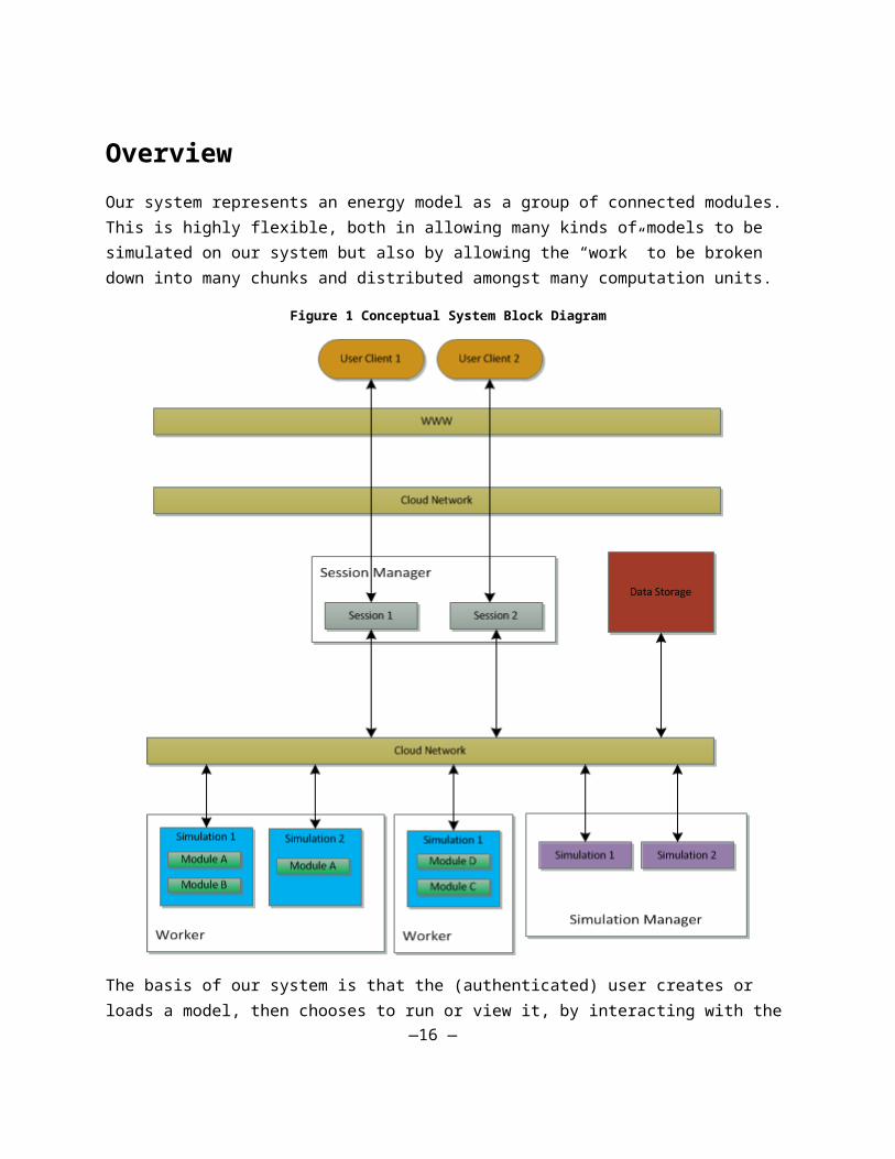
OverviewOur system represents an energy model as a group of connected modules. This is highly flexible, both in allowing many kinds of models to be simulated on our system but also by allowing the “work” to be broken down into many chunks and distributed amongst many computation units.
Figure 1 Conceptual System Block Diagram
The basis of our system is that the (authenticated) user creates or loads a model, then chooses to run or view it, by interacting with the Session Manager (as above). To obtain a view of the model for a user, the Session Manager retrieves the results from Data Storage and formats them and sends them to the User Client.
—13 —

The Session Manager instructs the Simulation Manager to simulate the specified model and plan together. The Simulation Manager then creates a representation of a simulation (e.g. the purple “Simulation 1”), which creates the relevant Simulation parts on each available Worker. Modules in simulations that are split among multiple Workers communicate with each other through the Cloud Network, using services provided by the simulation grouping (e.g. the blue “Simulation 1.”) Results, when created, are placed in Data Storage for the Session Manager to access and provide to the user whenever the user requests it.
System and DependenciesOur simulation framework, at heaviest use, will be running an arbitrary number of simulations with arbitrary complexity, parceled out to different users. At lightest use, it will be running no simulations, and only serving up static results from previously run (and published) simulations. The client could handle high demand by running a large server farm, but that has its own costs, and is a rather hefty investment. The client could choose to strictly limit the amount of power available to the system, thereby reducing costs, but also usability.
However, neither of these solutions is particularly desirable. An ideal solution would rather scale up when demand is high (with a cap, of course) but also be able to shrink down when demand is low. The system should also require minimal maintenance from the client.
To solve these problems, our simulation framework will run on Microsoft's Azure cloud computing platform. Azure supports hosting web applications, allowing the public to easily access simulation results through the Internet. Using Azure will allow us to meet the requirement of efficiently utilizing system resources because computing resources in Azure can be automatically scaled up and down on demand. Furthermore, Azure eliminates the need for the customer to buy, administer, and maintain computing infrastructure.
EventsThe framework must also be able to allow for events to occur at specific times in the simulation. These actions will be changes in the functionality of a set of modules. Events can effect both small and large changes in the overall model, from affecting a small section of a single module’s internal workings to changing the logic in several modules. These actions can be turned on or off and moved in time (and potentially repeated) by the user, but the events that are possible for a module are defined by the module itself. That is, a user cannot add an event to a module without editing the actual model implementation.
User InterfaceThe GUI was designed to enable the viewing of the plan and computed results graphs by all users, as well as the editing of these plans by authenticated and expert authenticated users. The GUI is split into 3 components to accomplish this:
—14 —

Graph/Model View
The Graph/Model View is designed to allow any user of this website to view the model, as well as the returned graphs of that particular simulation run. The interconnection of modules is shown in the center using blocks and lines, in order to illustrate the concept of the interconnectedness between these modules. Double clicking on modules will open the assumptions present in the module, and authenticated users will be allowed to edit their values. Clicking on the various tabs will switch between different returned line graphs, allowing the user to view and compare the results of simulations.
Timeline
The Timeline (top right) section of the screen is the representation of the energy plan. The events that occur in a given plan will be displayed chronologically in this view, to show which events occur and at which years. This view is placed directly over the graph, so that they can have similar time-steps (as an x-value), and the effects of events can be seen directly in the graph below.
Events List
The events list on the left will appear once a user has logged in as either an Authenticated User or an Expert Authenticated user. This list is a central location where authenticated users will be able to see the available events that they can use to create the energy plan. Authenticated Users will be able to create and edit events in the Timeline using this view. In addition to events, Expert Authenticated Users will be able to add in module components from this view.
—15 —
—16 —

—17 —

ImplementationSimulation Framework ImplementationOur implementation of the simulation framework has four overall components: the User Client Web Front-End, the Server Back-End, the Simulation Manager, and a set of Worker Handlers. The User Client Web Front-End contains the user-facing portion of our framework. This consists of a website that users can access using their Internet browser of choice. The Web Front-End will be written using standard HTML 5, CSS, and JavaScript technologies to maximize portability across various browsers. Each user's browser client is henceforth referred to simply as a "User Client." An arbitrary number of User Clients can be in communication with our system at any given time; this is made possible by the scalability of Azure web hosting services. The Server Back-End resides in Windows Azure and acts as the access point through which User Clients communicate with the rest of our system. The Server Back-End consists of a Session Manager and a network interface to communicate with other components of our system.
The Session Manager uses Windows Live ID authentication to identify and track users. Each Live ID corresponding to one user is associated with a privilege level, which can be adjusted by system administrator. The Simulation Framework differentiates between requests for different users with their live ID.
The Simulation Manager handles requests to run new simulations by creating a Simulation Instance for each new simulation. The Simulation Instance issues commands through the Worker Interface to initialize all modules (including assumptions and plan events) and connections between modules in the simulation.
The Simulation Instance constructs the entire simulation as one composite module which contains the various modules (including other composite modules) for the simulation. The function of a composite module is to route its inputs to the modules it contains as well as route the outputs of its inner modules to modules outside the composite. Also, every composite module can run on a different time scale, allowing inner composite modules to simulate finer-grained time scales than its enclosing module. For example, the outermost composite module can simulate on a yearly time scale, while its inner modules simulate monthly events. This type of compositing allows our framework to simulate an arbitrarily complex simulation. The Worker Interface assigns each module to a Worker Handler through the Simulation Network Layer. Each Worker Handlers runs on a specific Azure Virtual Machine and encloses several running modules. Spreading the different modules of the simulation across several Virtual Machines allows our framework to utilize Azure’s resources more effectively and provides the ability to simulate very complex simulations.
—18 —

Communication between the Worker Interface and running modules goes through the encapsulated Simulation Network Layer. This network layer is responsible for distributing modules across various Virtual Machines and routing communication between modules.
—19 —

GUI Implementation
Basic Users
—20 —

—21 —

Authenticated Users
—22 —
—23 —

—24 —