system overview model 1122 reject gate control technology bruce t. dobbie
TRANSCRIPT

System OverviewSystem Overview
Model 1122 Reject Gate Control TechnologyBruce T. Dobbie

Mission StatementMission Statement
Splice Detector Technologies is a designer and manufacturer of high speed splice, tearout, missing ply and web break detection equipment and related
products. We are committed to the industry and our customers that depend on us to ensure that
quality is maintained at the highest possible level. We are dedicated to increasing customer
satisfaction, continuously improving our products and services, and providing opportunities for our employees to achieve their maximum potential.

Product: Reject Gate/Control TechnologyProduct: Reject Gate/Control Technology
http://www.splicedetector.net/splicedetector_products/reject_gate_control.html orhttp://www.splicedetector.com/splicedetector_products/reject_gate_control.html
FOR MORE INFO...

TechnologyTechnology

System OverviewSystem Overview
The Model 1122 Reject control computer is intended for fully automating the cutting/sorting application, providing an automatic reject facility for defective sheets. Typically installed between the automatic sorting and inspection system, the reject control computer ensures that the product is inspected, cut or sorted automatically without intervention by operators. This method of operation provides faster and more reliable defect rejecting capability. The 1122 rejects defective sheets regardless of operation speed. In any application, if the defect occurs in such a manner that it is bisected by the knife, the system's accuracy will ensure that both sheets are rejected (assuming margin inhibit is not employed).

System OverviewSystem Overview
The model 1122 receives three (3) types of information from the inspection system that is stored in digital memory. First it provides a pulse corresponding to the hole defect when it passes the inspection line. Second, it receives a synchronizing pulse that corresponds to future cut lines (trailing edges), and third, a synchronizing pulse relative to the instant cut and the reject line to determine when to move the deflector safely before the leading edge of the defective sheet approaches the deflector. The model 1122 also can determine how many complete sheets and parts (fraction) of one sheet are between the inspection line and rejection line. The system is capable of memorizing up to 16 sheet lengths from the inspection line to the reject line. As safety, a margin inhibit switch disengages the reject mechanism when a defect falls within 1/4"(6.35 mm) of the cut line, (i,e., within a margin which will be trimmed later).

Theory of OperationTheory of Operation The Model 1122 Reject Control Computer is comprised of 4 modules
and a shaft encoder. The shaft encoder is mechanically linked to the knife of a cutter via direct coupling or a timing belt and timing belt pulley. The signals generated by this shaft encoder are two. One signal is 1 pulse per rotation of the shaft encoder, the other signal is 1000 pulse per rotation of the encoder
Theory of OperationTheory of Operation
To set the encoder the 1 pulse per revolution must occur. That is the pulse must be high ‑ 12 volts when the knife is 50% through the cut. This pulse is called the "zero" pulse or "marker" pulse. The other signal is continuous with the rotation of the knife. The 3 modules are called the "DCM" or "Detector Control Module", "GCM" or "Gate Control Module" and the PSM "Power Supply and Gate Control Module". Shaft encoder signals are introduced into the GCM and are conditioned, that is they go to a squaring circuit to make nice, clean, sharp, rise and fall pulses, they are then fed to circuits in both the DCM and GCM. These pulses are used to define "future cut line pulse" in the DCM when a "future cut line" passes the detector. A "leading edge" pulse is generated in the GCM to define when a "leading edge" of a sheet is approaching the "reject gate". If a sheet with a splice on it approaches the "reject gate" it will open and stay open for 1 full sheet length and then close. If there is splices on sequential sheets, the reject gate will stay open until the next clean sheet approaches the reject gate, then it will close again.

Features and BenefitsFeatures and Benefits
Can be utilized with any type of web based material that is being slit, cut and sorted.

Features and BenefitsFeatures and Benefits
Can be interfaced with any inspection system from any company monitoring one or multiple webs. Widely used with SDT splice detectors and FCS-WIS systems.

Features and BenefitsFeatures and Benefits
Unaffected by material basis weight changes, color, defect types or process speed.

Features and BenefitsFeatures and Benefits
Unaffected by printed material.

Features and BenefitsFeatures and Benefits Special splice tapes or color marking do not affect detection
and rejection.

Features and BenefitsFeatures and Benefits The 1122 Reject Control Technology incorporates state-of-
the-art electronic design circuitry, components, filtering and processing techniques unequaled in the industry.

Features and BenefitsFeatures and Benefits
State-of-the-Art Proprietary Processing.

Features and BenefitsFeatures and Benefits Highly visible indicator lamps and optional audio/visual
alarms provide immediate alert to operational staff. Provide user friendly outputs you can actually use too process control instrumentation.

Features and BenefitsFeatures and Benefits Military type connections ensure solid electrical
specifications are maintained and environmental protection is achieved.

Features and BenefitsFeatures and Benefits
Automatic calibration verification of sheet length and reject settings.

Features and BenefitsFeatures and Benefits
Meets quality initiative and ISO requirements.
Operation 24/7 without the need for operational intervention.
Eliminate the need for manual rejection of defects.

ApplicationsApplications
SheetersOr any process machine that has
rejection capabilities

Detection ResultsDetection Results The result is the rejection of any defect or splice type fault.

Power RequirementsPower Requirements
Inputs required ‑ 115 VAC, 50‑60 cps, 1 ampDefect signals ‑ Positive going 12 +/‑ 3 volt pulses of at least 100 microsecond duration are required. These may originate from an detecting equipment such as the R.K.B. Model 1032 Splice Detector or other devices.Pulse Generator ‑ The pulse generator provided
with equipment must be installed by the customer such that it is coupled to the knife cutter at a ratio of 1:1 exact.
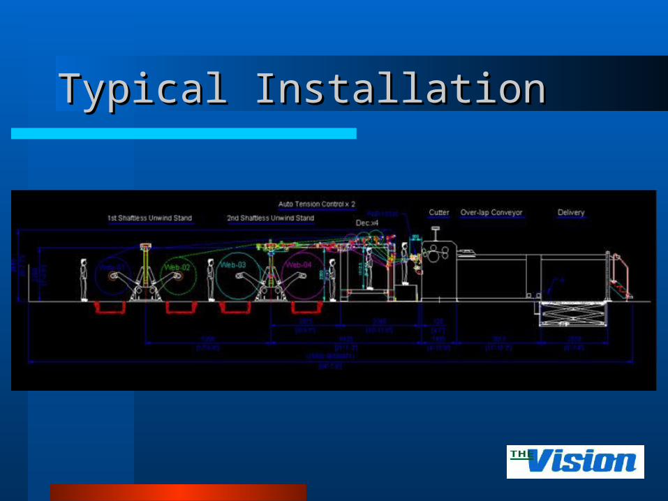
Typical InstallationTypical Installation

Typical InstallationTypical Installation

Typical InstallationTypical Installation

Installation at Major Paper MakerInstallation at Major Paper Maker

ReferencesReferences
For reliability; large, medium and small companies turn to SDT for their reject control technology needs.

Related WebsitesRelated Websites
http://www.rkbopto.com– Syracuse, New York, United States
http://rkb.chinapaper.net– Suzhou, Jiangsu, China
http://www. fioproin.it– Milan, Italy
http://www.swallowmachinery.com/– Meltham, Holmfirth, United Kingdom
http://www.quality2process.com– Delden, Netherlands
http://www.splicedetector.net / www.hole-detection.com / www.webinspection.us / www.splicedetector.com– Syracuse, New York, United States