system-of-systems viewpoint for system architecture
TRANSCRIPT

System-of-Systems Viewpoint for SystemArchitecture Documentation
John Klein∗ and Hans van Vliet†
VU University, Amsterdam, Netherlands
Revised 11 Nov 2017
AbstractContext: The systems comprising a system of systems (SoS) are inde-pendently acquired, operated, and managed. Frequently, the architecturedocumentation of these existing systems addresses only a stand-aloneperspective, and must be augmented to address concerns that arise in theintegrated SoS.Objective: We evaluated an architecture documentation viewpoint toaddress the concerns of a SoS architect about a constituent system, tosupport SoS design and analysis involving that constituent system.Method: We performed an expert review of documentation produced byapplying the viewpoint to a system, using the active review method.Results: The expert panel was able to used a view constructed usingthe baseline version of the viewpoint to answer questions related to allSoS architect concerns about a constituent system, except for questionsconcerning the interaction of the constituent system with the platform andnetwork infrastructure.Conclusions: We found that the expert panel was unable to answercertain questions because the baseline version of the viewpoint had a gapin coverage related to relationship of software units of execution (e.g.,processes or services) to computers and networks. The viewpoint wasrevised to add a Deployment Model to address these concerns, and isincluded in an appendix.
Keywords: architecture documentation; system of systems; viewpoint defi-nition; active review; expert panel; design cycle
1 IntroductionA system of systems (SoS) is created by composing constituent systems. Eachconstituent system retains operational independence (it operates to achieve
∗[email protected], Corresponding author†[email protected]
1
arX
iv:1
801.
0683
7v1
[cs
.SE
] 2
1 Ja
n 20
18

a useful purpose independent of its participation in the SoS) and managerialindependence (it is managed and evolved, at least in part, to achieve its own goalsrather than the SoS goals) [1]. In order to assess suitability of the system foruse in the SoS and to reason about SoS functionality and quality attributes, thearchitect of a SoS relies on documentation about the constituent system. In anideal world, constituent system documentation would be available and address allSoS concerns. Our previous research (discussed in Related Work below) reportsthat this is not usually the case [2]. The challenge of documenting architectureswhose parts are designed by separate organizations is a fundamental challengeof SoS and ultra-large scale systems [3].
Pragmatically, the SoS architect seeking information about a constituentsystem has limited options. If there is documentation and/or source codeavailable, the SoS architect can attempt to learn enough about the constituentsystem design to address concerns about how that system will operate in theSoS. However, constituent systems are developed independently, and often thereis limited or no access to documentation or code. The architect of the SoS couldseek to collaborate with the architect of each constituent system to augmentthe constituent system architecture documentation with the information neededto address the SoS concerns. However, the managerial independence of thedevelopment and evolution of constituent systems within a SoS [1] often createsbarriers to collaboration. Consider three examples of these barriers:
1. Each constituent system owner retains independent management of fundingand objectives, and the constituent system architect’s responsibilities fordelivering system-oriented capabilities may not provide slack time to allowcollaboration with the SoS architect.
2. There is no ongoing development on a particular constituent system, and sothere is no architect assigned who could collaborate with the SoS architect.
3. Firms are integrating IT systems after a merger or acquisition, and thearchitects of particular acquired systems have been reassigned or dismissed,and so are not available to collaborate.
In each of these scenarios, collaboration between the SoS architect and thearchitects of each constituent system may become a tightly planned and managed,high ceremony event. The SoS architect must articulate a precise request forinformation, for which the constituent system architect estimates the cost torespond. The SoS owner and the constituent system owner negotiate to fund theconstituent system architect’s work to respond, and eventually the constituentsystem architect is directed to supply the requested information to the SoSarchitect. There is often little or no ability to iterate the information requests orseek elaboration of the responses, and given these high stakes, the architect ofthe SoS needs a pedigreed basis for a request for information.
The contribution of this paper is an architecture documentation viewpointto assist SoS architects in collecting or creating sufficient documentation aboutconstituent systems in a SoS. The viewpoint addresses stakeholder concerns
2

about SoS design and analysis. This reusable “library viewpoint” conformsto the ISO/IEC 42010 standard for architecture description [4], and providesguidance for SoS architects to request sufficient information about constituentsystem architectures to satisfy SoS-level concerns about each constituent systemoperating in the SoS context. The viewpoint was evaluated by an expert panelin a single case mechanism experiment using the active design review method [5].We found that the baseline version of the viewpoint covered most SoS stakeholderconcerns; however, the experiment uncovered a gap in the area of deployment ofsoftware units to computers and networks. We describe how the viewpoint wasreworked by adding a new model kind to address this gap.
This paper is organized as follows: §2 discusses related work in the areas ofSoS and architecture documentation. §3 describes our approach to developingand evaluating the viewpoint, which was based on Wieringa’s design cycle [6].§4 presents the results of our evaluation experiment, and our analysis andinterpretation, including how the baseline version of the viewpoint was reworkedbased on the results of the experiment. §5 summarizes our conclusions, and thereworked viewpoint is included as an appendix.
2 Related WorkGenerally, concern-driven architecture documentation approaches organize archi-tecture documentation into views to address stakeholder concerns [4, 7, 8]. Theseapproaches are widely used for software system architecture documentation, forexample in the Rational Unified Process (RUP) 4+1 Views [9].
At the SoS level, view-based frameworks such as DoDAF [10] and MODAF[11] have emerged to document SoS architecture. The EU COMPASS Project[12], which ended in 2014, addressed SoS modeling, and SoS architecture doc-umentation continues to be an area of active research [13], producing newdocumentation approaches such as S3 [14] and SySML-based approaches fromthe EU AMADEOS project [15].
The architect of a SoS must depend on the documentation of constituentsystems. Our earlier research reported that one challenge to designing a SoSarchitecture is gaps in the architecture documentation of the constituent systems[2]. The architecture documentation of each constituent system usually focuseson the stand-alone operation of that system, and on the stand-alone developmentand evolution of that system. The architecture documentation for constituentsystems is created during engineering development of the constituent system,for different purposes than SoS, notably constituent system bounds, constituentsystem goals, different modeling goals, and different characteristics of interest [16].While functional interaction with external systems in support of the system’sstandalone operation may be addressed by the architecture documentation, thequality attribute aspects of those interactions are typically not well covered.
Participation of a constituent system in a SoS introduces new concerns aboutthat system; however, a survey by Bianchi and colleagues found that there areno applicable quality attribute frameworks for these concerns [17]. Our earlier
3

research found interoperability to be a primary concern of SoS designers [18], andmore recent work by Batista [19] and by Guessi and colleagues [13] confirmedthat interoperability is a primary focus of SoS architecture documentation.The system mission characterization of Silva and colleagues provides insightinto functional interoperation concerns [20]. Architecture documentation forconstituent systems that addresses standalone operation may not address SoSinteroperability concerns, which go beyond interface syntax. As the contextfor interface semantics is expanded to the SoS, behavior that might have beenconsidered private to the system becomes externally visible. For example, designdecisions such as whether to retry a failed request to an external system may notbe architectural in the context of standalone operation, but become externallyvisible and architectural in the context of SoS operation.
The viewpoint that we developed could be considered an extension of theSystem Context Viewpoint defined by Woods and Rozanski [21], or of the systemcontext diagram in the Beyond Views section of a Views and Beyond architecturedocument [7]. However, each of these focuses on how external interfaces andinteractions support the independent operation of the system, and not on howthe system interoperates with other systems to achieve an SoS capability.
3 ApproachOur objective is to design an artifact that contributes to the achievement of somegoal. Here, the artifact is an architecture viewpoint, and the goal is to allow SoSarchitects to reason about a constituent system to design a SoS. Wieringa labelsthis a design problem and we used the Design Cycle approach [6] as follows:
1. Problem Investigation—We built on the related work discussed above toidentify stakeholders in the SoS design process and their concerns relatedto constituent systems operating in the SoS context.
2. Treatment Design—We defined an architecture viewpoint to address thosestakeholder concerns.
3. Treatment Evaluation—We evaluated the treatment by a single case mech-anism experiment [6], using an expert panel to conduct an active designreview [5].
3.1 Problem Investigation—IdentifyStakeholders and Concerns
There are many stakeholders in a SoS and in its architecture [22]. Our focus ison the architecture design and analysis task, and specifically, reasoning about aconstituent system in the context of the SoS, which narrowed the scope to thestakeholder roles listed in Table 1.
These stakeholders were selected because they are directly involved in un-derstanding the constituent system architectures, proposing or defining changes
4

Table 1: Selected SoS Architecture Stakeholders
Stakeholder Name Stakeholder Role
SoS Architect Creates architecture designs to allow con-stituent systems to interoperate to achieveSoS goals. Proposes or defines necessary ordesirable changes to constituent systems.
SoS Program Manager Has ultimate responsibility for achievingSoS goals. Negotiates with program man-agers of constituent systems to make nec-essary or desirable changes to constituentsystems.
Developer Makes necessary or desirable changes to thesoftware of the constituent systems.
SoS Testers and Integrators Installs, configures, and tests the con-stituent systems interoperating as a SoS.
to those architectures for use in the SoS, and then constructing, testing, andintegrating the constituent systems in the SoS.
Our earlier systematic review found that SoS research has heavily focusedon interoperability concerns [18], however, our state of the practice surveyindicated that practitioners designing and analyzing SoS architectures havebroader technical and non-technical concerns [2]. Since this treatment will beemployed by practitioners, we decided to augment the researcher-oriented findingswith a survey of practitioner-focused literature to identify additional concernsabout constituent systems when designing and analyzing SoS architectures.
The survey focused on an annual practitioner conference organized by theSystems Engineering Division of the National Defense Industry Association(NDIA)1. We reviewed all papers in the SoS Track and Architecture Track forthe conferences from 2009 through 2016, and identified 14 papers that discussedSoS architecture concerns. We also reviewed the United States Departmentof Defense Systems Engineering Handbook for Systems of Systems [23], whichprovides guidance to a broad community of practice. From these sources, weidentified a set of concerns that are shown in Table 2. As described below, theseconcerns were used to define the architecture viewpoint artifact.
3.2 Treatment Design—Define the Architecture ViewpointWieringa defines a treatment as “the interaction between the artifact and the prob-lem context” [6, §3.1.1]. We will define an artifact—an architecture viewpoint—that will be applied by an SoS architect to create an architecture view of aconstituent system that provides the information needed to reason about thatconstituent system when it is operating in the context of the SoS. In this section
1See http://www.ndia.org/divisions/systems-engineering
5

Table 2: SoS Stakeholder Concerns from Practitioner-oriented Literature
Publication Concerns about constituent systems in an SoS
Benipayo 2016 [24] Dependencies on other constituent systems
Sitterle 2016 [25] Interface adaptability (Interoperability), Recovery
Gump 2014 [26] Interoperability, Dependencies on other constituent sys-tems
Manas 2014 [27] Dependencies on other constituent systems, Shared Re-sources
Carson 2014 [28] Dependencies on other constituent systems
Guertin 2014 [29] Portability, Scalability, Dependencies on other constituentsystems, Security
Baldwin 2014 [30] Stakeholders, Dependencies on other constituent systems
Gagliardi 2013 [31] Shared resources
Pritchett 2013 [32] Dependencies on other constituent systems
Dahmann 2012 [33] InteroperabilityPerceived needs of constituent systemsProcesses, cultures, working practices between differentparticipating organizationsDependencies at development time and run time
Dahmann 2012 [34] Dependencies on other constituent systems
Smith 2011 [35] Interoperability context: assumptions, constraints, drivers
Lane 2010 [36] Monitoring and measurement
DoD 2008 [23] Technical and organizational dependenciesInteroperabilitySynchronization of delivery of features across constituentsystems (dependencies)Constituent system stakeholdersConstituent system needs and constraintsConstituent system evolution strategy and built-in vari-abilities
we focus on the design of the architecture viewpoint, however, our evaluationwill consider the entire treatment.
The viewpoint definition conforms to the ISO/IEC/IEEE 42010 standard [4],using Annex B of that standard as the template for the viewpoint specification.This approach was selected because of its status as a global standard and becauseit is compatible with producing documentation using other approaches such asViews and Beyond (see, for example, Appendix E in [7]).
The subset of the ISO 42010 conceptual model related to viewpoint definitionis reproduced in Fig. 1.
6

architecture
viewpoint
stakeholderconcern
view
model
has 1..*
frames 1..*
model
kind
1..*
1..*
governs 11
governs 11
1..*1..*
Key: UML 2.0
Figure 1: Extract from ISO 42010 Conceptual Model (Adapted from [4])
As shown in Fig. 1, the viewpoint definition begins by identifying stakeholdersand concerns. The concerns identified in Table 2 are somewhat general. In orderto define an architecture viewpoint to address the concerns, we refined theseby mapping them to the set of quality attributes that Bass and colleagues [37]defined and found to be relevant to all software systems, namely performance,availability, security, testability, modifiability, and usability. In Table 3, weconsider each of these quality attributes (along with a category for concernsabout the system context that are shared by many stakeholders) as concernsat the SoS level, and then trace down to information needed at the constituentsystem level in order to address the SoS concern. This tracing was performed byconsidering the tactics [37] that might be applied to achieved the quality. Tacticsthat could be applied in the SoS context became concerns about constituentsystems in Table 3. Bass and colleagues also discuss which stakeholders aretypically concerned with each quality attribute, and we include this informationin Table 3. Note that the SoS architect is concerned with all qualities.
Fig. 1 shows that the viewpoint comprises one or more model kinds. Themodel kinds were developed iteratively, using the following approach:
1. Identify the type of elements and relations needed to address each concern.
2. Group concerns that had the same types of elements and relations.
3. Define a model kind for each group of concerns.
Following this approach, we developed five model kinds, each addressingparticular concerns from Table 3, and collectively addressing all concerns. Themodel kinds are listed below. Each model kind includes a brief discussion ofthe model elements and relationships, and the complete definition of the modelkinds is provided in the appendix:
7
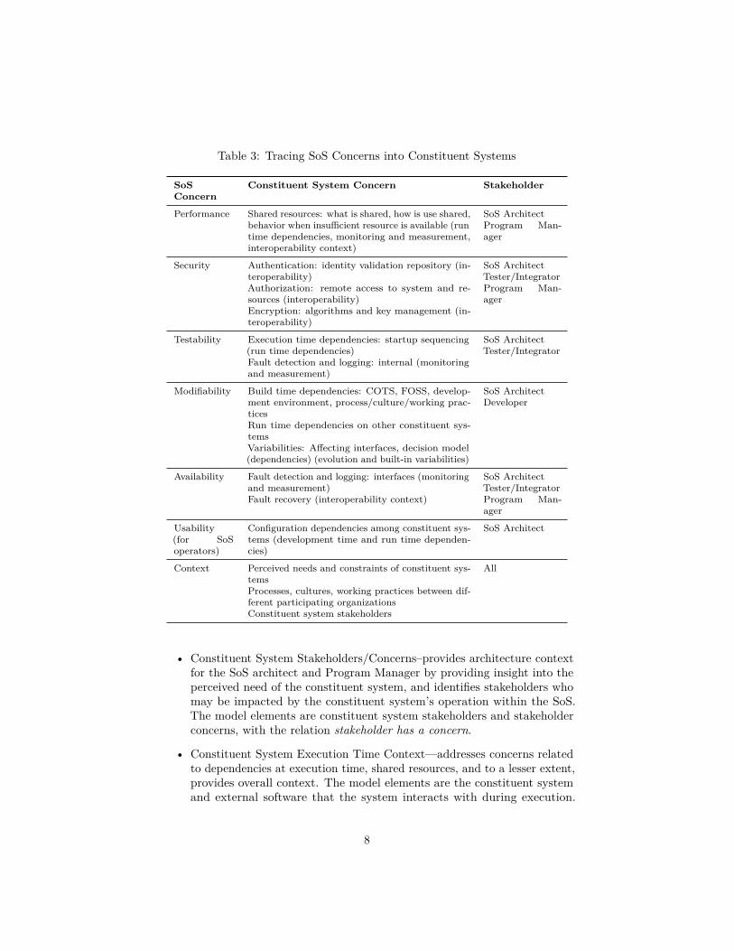
Table 3: Tracing SoS Concerns into Constituent Systems
SoSConcern
Constituent System Concern Stakeholder
Performance Shared resources: what is shared, how is use shared,behavior when insufficient resource is available (runtime dependencies, monitoring and measurement,interoperability context)
SoS ArchitectProgram Man-ager
Security Authentication: identity validation repository (in-teroperability)Authorization: remote access to system and re-sources (interoperability)Encryption: algorithms and key management (in-teroperability)
SoS ArchitectTester/IntegratorProgram Man-ager
Testability Execution time dependencies: startup sequencing(run time dependencies)Fault detection and logging: internal (monitoringand measurement)
SoS ArchitectTester/Integrator
Modifiability Build time dependencies: COTS, FOSS, develop-ment environment, process/culture/working prac-ticesRun time dependencies on other constituent sys-temsVariabilities: Affecting interfaces, decision model(dependencies) (evolution and built-in variabilities)
SoS ArchitectDeveloper
Availability Fault detection and logging: interfaces (monitoringand measurement)Fault recovery (interoperability context)
SoS ArchitectTester/IntegratorProgram Man-ager
Usability(for SoSoperators)
Configuration dependencies among constituent sys-tems (development time and run time dependen-cies)
SoS Architect
Context Perceived needs and constraints of constituent sys-temsProcesses, cultures, working practices between dif-ferent participating organizationsConstituent system stakeholders
All
• Constituent System Stakeholders/Concerns–provides architecture contextfor the SoS architect and Program Manager by providing insight into theperceived need of the constituent system, and identifies stakeholders whomay be impacted by the constituent system’s operation within the SoS.The model elements are constituent system stakeholders and stakeholderconcerns, with the relation stakeholder has a concern.
• Constituent System Execution Time Context—addresses concerns relatedto dependencies at execution time, shared resources, and to a lesser extent,provides overall context. The model elements are the constituent systemand external software that the system interacts with during execution.
8
The relations are execution time interactions, e.g., sends/receives message,call/return, read/write data, etc.
• Constituent System Code Context—addresses concerns related to imple-mentation dependencies. The model elements are the constituent systemsoftware, and external modules (e.g., libraries, development tools, packages,etc.). The relation is uses.
• Constituent System Interface Information Model—addresses concerns re-lated to semantic interoperation of data elements. The elements areinformation elements of interest to the SoS (e.g., a SoS that deals withgeo-location might use concepts like position, elevation, and direction),and information elements in the constituent system software. Relations arelogical associations (1-to-1, 1-to-N, N-to-M), specialization/generalization,and aggregation.
• Shared Resource Model—addresses concerns about runtime resource shar-ing. Elements are components in the SoS representing resources used bythe constituent system and by other systems, including processor computecycles, memory, disk space, network bandwidth, files, databases, virtualinfrastructure, or physical resources such as a display, antenna, or radiofrequency. Relations are acquires/releases and consumes.
Table 4 shows the mapping from the concerns listed in Table 3 to the modelkinds listed above.
The 42010 standard permits three approaches to accommodate multiplemodel kinds:
• Define multiple independent viewpoints, with each viewpoint comprising asingle model kind. We rejected this approach because the models are notindependent: In our case, omitting one model kind leaves a set of concernsuncovered.
• Define a framework that comprises multiple viewpoints, with each viewpointcomprising a single model kind. The standard characterizes a framework as“establishing a common practice. . . within a particular domain of applicationor stakeholder community” [4, §4.5]. We rejected this approach for tworeasons: The resulting artifact was applicable beyond a single applicationdomain, and a framework does not inherently imply that all viewpoints areused together, and so we have the model omission issue described above.
• Define a single viewpoint that comprises multiple model kinds. We selectedthis approach because it treats the set of model kinds as an atomic unit.
The single viewpoint was titled “SoS Constituent System Viewpoint”. Thecomplete viewpoint definition that conforms to the ISO 42010 standard ispresented in the appendix to this paper (§6 below).
9

Table 4: Mapping Concerns to Model Kinds
Concern (from Table 3)Model kind(s) thataddress the concern
Shared resources—what is shared, how is use shared Shared ResourceExecution Time Con-textDeployment
Behavior when insufficient resource is available (run time de-pendencies, monitoring and measurement, interoperability con-text)
Shared ResourceInterface InformationExecution Time Con-text
Authentication—identity validation repository (interoperabil-ity)
Interface InformationShared ResourceExecution Time Con-text
Authorization—remote access to system and resources (inter-operability)
Interface InformationShared ResourceExecution Time Con-text
Encryption—algorithms and key management (interoperabil-ity)
Interface InformationShared ResourceExecution Time Con-text
Execution time dependencies—startup sequencing (run timedependencies)
Execution Time Con-textDeployment
Fault detection and logging—internal (monitoring and mea-surement)
Interface InformationExecution Time Con-text
Fault recovery (interoperability context) Execution Time Con-textDeployment
Build time dependencies—COTS, FOSS assumptions Code Context
Development environment dependencies (development timedependencies, process/culture/working practices)
Code ContextDeploymentStakeholder/Concerns
Variabilities affecting interfaces Interface Information
Decision model (dependencies, evolution and built-in variabili-ties)
Code ContextInterface Information
Configuration dependencies among constituent systems (devel-opment time and run time dependencies)
Code ContextExecution Time Con-textInterface Information
Perceived needs and constraints of constituent systems Stakeholder/Concerns
Processes, cultures, working practices between different partic-ipating organizations
Stakeholder Concerns
Constituent system stakeholders Stakeholder/Concerns
10

3.3 Treatment Evaluation—Active Design Review byExpert Panel
Treatment evaluation is “the investigation of a treatment as applied by stake-holders in the field. . . to investigate how implemented artifacts interact withtheir real-world context” [6, §3.1.5]. Our evaluation criteria were that the view-point provides sufficient coverage of concerns, and that a view created using theviewpoint provides sufficient detail to allow an SoS architect to reason aboutthe constituent system operating in the context of the SoS.
The Introduction, above, described the high stakes involved in acquiringdocumentation about constituent systems, arising from the managerial indepen-dence of the systems. Therefore, an initial evaluation of this untested treatmentthrough an observational case study [6, §17] or through technical action research[6, §19] would not be a responsible approach. We chose to perform a single casemechanism experiment [6, §18] using an expert panel, to complete the initialevaluation without impacting a real-world project. Expert panel assessmenthas been used by a number of researchers (e.g., Dyba [38], van den Bosch andcolleagues [39], and Beecham and colleagues [40]), and so we saw this approachas both prudent and appropriate for an initial evaluation of an untested artifact.According to Hakim [41], small samples are effective to test explanations, partic-ularly in the early stages of work. Expert panel recruitment is discussed belowin §3.3.4, and panel demographics are shown below in §4.1.
Our treatment artifact is architecture documentation. Nord and colleaguesprovide a six-step structured approach to reviewing architecture documentation[42], which we followed for our evaluation. Steps 1-5 are discussed in subsequentsubsections, and the results of the review (Step 6) are discussed below in §4.This six-step process is comparable to the eight-step process used by Beechamand colleagues [40], collapsing multiple process steps in several places.
3.3.1 Step 1: Establish the Purpose of the Review
We aim to produce an artifact to guide an SoS architect to request the architectureinformation about a constituent system that is sufficient for the architect andother stakeholders to reason about that system in the context of a SoS.
As discussed above, our criteria for the treatment evaluation were that theviewpoint provides sufficient coverage of concerns, and that a view created usingthe viewpoint provides sufficient detail to allow an SoS architect to reason aboutthe constituent system operating in the context of the SoS.
3.3.2 Step 2: Establish the Subject of the Review
We are evaluating the treatment: the artifact applied in context, specificallythe viewpoint applied to a system to produce an architecture view. For this,we applied the viewpoint to the Adventure Builder system, which was chosenbecause it has an openly available architecture description to use as the basisfor constructing the view documentation.
11

The Adventure Builder system is a reference application, developed for aa fictitious company that sells adventure travel packages that bundle airlinetransportation, hotel accommodations, and guided activities. The system has acustomer-facing website that allows customers to shop and purchase adventurepackages, and a service-oriented architecture back-end that integrates withexternal payment processing and travel provider services.
The view documentation that was produced is available as part of the reviewinstrument, shown below in §7.
3.3.3 Step 3: Build or Adapt Appropriate Question Sets
Nord and colleagues identified several review styles:
• Questionnaire—reviewers assess the artifact using a list of questions pro-vided by the review organizer.
• Checklist—reviewers rate the artifact using a list of yes/no questions (aspecial case of the questionnaire style).
• Subjective review—stakeholders also play the role of reviewer and posequestions to themselves.
• Active review—architects ask questions that require reviewers to use thesubject artifact in order to answer the questions.
We chose to use an active review style, as this approach ensures that the reviewersskim the entire artifact and read some parts of the artifact in detail. It alsoevaluates the treatment (artifact in use), and not just the contents of the artifact.
However, we also wanted to understand how our experts would use theirknowledge and experience to approach a SoS design problem, and so we incorpo-rated a subjective review, where each expert formulated questions about a SoSdesign problem, and then later in the review, answered these as active reviewquestions.
The instrument we created for the review had multiple parts (see §7, below):
1. Demographic information about the reviewer.
2. A narrative vignette that created a usage scenario for the architectureview. It asked each reviewer to play the role of a SoS architect tasked tointegrate the Adventure Builder system into an SoS, and specified a designproblem with three new SoS capabilities.
3. Subjective review questions—we asked each reviewer to record three ques-tions that they had about the architecture of the Adventure Builder system,related to the design problem.
4. We next provided the architecture view artifact.
12
5. For each of the three new capabilities, we created several questions aboutthe new SoS design, and the reviewer had to use the architecture view toanswer the questions.Our questions were refined from the “Key Design Decisions” question listfrom Nord and colleagues [42, §4.5]. Two examples of the questions areshown here; the entire instrument is contained in the Appendix in §7.
• Does the Adventure Builder system have existing request-responseinterfaces with external systems? If so, what protocols/technologiesare used for these interfaces?
• The inputs to the new payment processing interface are: Card Type,Card Number, Card Expiration, and Card Security Code/CCV. Canthe current Adventure Builder system provide all of these elements?
Reviewers also answered the three subjective review questions that theycreated earlier in the review. We asked reviewers to annotate their responsesindicating the document sections that they consulted to answer eachquestion. We wanted to limit the duration of the review exercise to onehour, and so we presented eight active review questions, which along withthe three subjective review questions, required each reviewer to answer atotal of 11 questions.
6. The instrument concluded by recording the amount of time that thereviewer spent, and with open-ended questions about the realism of thescenario, the contents of the architecture view, and any comments aboutthe review exercise.
3.3.4 Step 4: Plan the details of the review
Nord and colleagues define three major activities in this step: Constructing thereview instrument in light of constraints and intentions for reporting results;identifying actual reviewers; and planning review logistics.
Our review instrument is outlined above in §3.3.3. It includes the questionset, reflects how we addressed review time constraints, and collects demographicand other information to support our reporting of research results. We decidedto present all reviewers with the same set of eight active review questions (i.e.all participants were assigned the same treatment).
Experts were recruited from a population of experienced practitioners in theareas of SoS and enterprise system integration, who have worked in the fieldfor several years and have been responsible for designing the architecture forseveral SoS. Experts were targeted to represent different backgrounds and systemdomains, as recommended by Kitchenham and colleagues [43]. Additionally,we sought geographic diversity and organizational diversity. We recruited eightexperts from eight different organizations to participate in the review exercise,and seven accepted.
13

Finally, our review logistics were simple: We emailed the instrument to eachreviewer, who worked independently to complete the review and return thecompleted instrument to us by email.
3.3.5 Step 5: Perform the Review
As noted above, we performed the review by sending an identical survey instru-ment by email to each reviewer, and receiving a completed instrument sent backto us by email.
4 Analysis and Results4.1 Expert Panel DemographicsThe expert panel demographics are presented in Table 5. These data wereself-reported by each expert. These data were collected to verify that the inviteemet the inclusion standards in §3.3.4, and to assess the diversity of experienceof the panel.
4.2 Active Review Question ResponsesHere we discuss responses to the eight active review questions that we createdand which were assigned to all reviewers.
All of the participants answered the eight active review questions correctly,with some minor variations in responses due to differing interpretations of thequestion wording and the context. In particular, the use of the unqualified term“interface” in several questions proved confusing: This was interpreted to meanprogrammatic interface or user interface, or both.
Six of the seven reviewers indicated which model(s) they used to answereach question (Some reviewers used more than one model to answer a question.).These responses showed that every model was used by at least one reviewer toanswer at least one question, indicating that the questions covered the breadthof the artifact.
Based on the small sample size (N=7), we hesitate to perform statisticalanalysis on the relationship between questions and models; however, we showthe frequency of each model’s use in Table 6.
4.3 Subjective QuestionsAs discussed above in §3.3.3, in addition to the eight active review questions thatwe developed, we asked each reviewer to specify three questions that they thoughtwere important for this design problem. In addition to helping triangulate toimprove the quality of evaluation (discussed in the next section), it provideddirect insight into an SoS architect’s concerns when presented with a designproblem.
14

Table 5: Expert Panel Demographic Information (N=7)
Variable Reported Value(s)
Current position title Software Architect (3)Chief Enterprise Architect (1)Chief Technical Officer (1)Solution Architect (1)Information Architect (1)
Current industry Consulting services—multiple industry do-mains (4)Government (2)Financial services (1)
Prior industry experience(multiple responses allowed)
Software product development (4)Financial services (2)Academia (2)Consulting services—multiple industry do-mains (1)Government (1)Utility (1)Telecommunications (1)Transportation (1)Defense (1)
Nationality USA (3)Netherlands (2)Brazil (1)UK (1)
Number of years of profes-sional experience developingor integrating systems
18-40 years (Average = 30, Median = 30)
Approximate number ofsystem integration projectsworked on
Responses ranged from 8 to “more than 100”.
Our seven reviewers posed three questions each. There was significant overlapamong these 21 questions, and we clustered the questions into six categories,shown in Table 7.
The questions in the Platform category could not be readily answered bythe reviewers using the architecture documentation provided. The viewpointincluded a Code Context model kind, which could represent the dependencieson platform code modules, including application containers, operating systemsand database libraries, and virtual machines. However, the viewpoint does notinclude a deployment model that would directly address this category of concernsby showing the relationship between the execution elements of the constituentsystem—processes, services, applications, etc.—to computer nodes and networks
15

Table 6: Active Review Coverage of Models
Model Name Number of times used toanswer active review question
Stakeholder/Concerns 13
Execution-time Context Model 12
Code Context Model 8
Interface Information Model 22
Shared Resource Model 3
Table 7: Subjective Question Categorization
Category Example Questions Frequency(N=21)
PlatformWhat is the platform/technologystack/runtime environment used by theconstituent system?
7
Data Model
What is the logical data model used inthe constituent system? How iscustomer-identifying or user-identifyingdata handled?
6
ImplementationQuality/Risk
What are the known problems in theconstituent system? What is thedevelopment history (internal, acquired,outsourced, etc.)?
3
User Interface What is the user interface exposed bythe constituent system? 2
FunctionalStructure
What is the functional structure of theconstituent system? 2
Architecturally-SignificantRequirements
What are the quality attributerequirements for the constituent system? 1
(e.g., [7, §5.2]).The questions in the Implementation Quality/Risk category address issues
that are important to understand when designing a SoS; however, this informationis not part of the architecture (i.e. structures comprising elements, relationships,and properties) of the constituent system, and these concerns can be addressedby reviewing or inspecting non-architectural artifacts such as an issue trackingsystem or source code repository.
The questions in the User Interface category could not be readily answered bythe reviewers using the architecture documentation provided. Further research is
16

needed into the underlying concern—a possible explanation is that the enterprisebusiness system context for the vignette that we used for the exercise triggeredthis concern based on the expert’s experiences, even though none of the desirednew capabilities involved the user interface.
The question about Architecturally-Significant Requirements was not readilyanswered by that reviewer using the architecture documentation provided. Acomplete ISO/IEC/IEEE 42010-compliant architecture description would containrationale that includes architecturally significant requirements [4, §5.8]. Ourreview instrument included only a subset of a complete architecture descriptioncontaining the view that was the subject of the evaluation, and the view containedmodels with no rationale.
Questions in the Data Model and Functional Structure categories were readilyanswered by the reviewers using the architecture documentation provided.
4.4 Interpretation and Viewpoint ReworkBased on the experiment results discussed above, we found that the baselineversion of the architecture viewpoint adequately covered the SoS stakeholderconcerns that we had identified in our Problem Investigation. However, ourexpert review panel’s subjective review questions uncovered three categories ofconcerns that we had not identified in our Problem Investigation, and were notaddressed by the baseline version of architecture viewpoint.
Below, we discuss each of these categories of concerns, and how the baselineversion of viewpoint definition was reworked to produce the fubak viewpointdefinition presented in the Appendix (§6).
4.4.1 Runtime Deployment Environment Concerns
The first category of concerns that was not addressed by the baseline versionof the architecture viewpoint involved the runtime deployment environment ofthe constituent system. The subjective review questions that raised this concerncovered two areas: the software platform (operating system, application server,database manager, service bus, etc.), and the physical deployment (mapping ofsoftware to compute nodes and networks).
In developing the viewpoint definition, we expected that the software platformconcerns would be addressed by the Execution Time Context Model and/or theCode Context Model; however, those models in the Adventure Builder Systemartifact provided to the reviewers did not contain sufficient detail to address theconcern. We have reworked the viewpoint definition by extending the “Elements”section of these two models to add the software platform elements to the model,and by extending the “What’s it for” section to add that the model is used toanswer questions such as those posed by the expert panel.
The physical deployment concerns arise from the distributed nature of aSoS. This physical distribution affects performance, availability, and possiblysecurity and other qualities. It is necessary for the SoS architect to understandthe physical deployment of the constituent system (how software is mapped to
17

compute and network resources) because, when the system becomes part of anSoS, those compute and network resources may be shared with other constituentsystems, or may be configured differently from the constituent system’s stand-alone architecture.
The Shared Resource Model definition identifies network bandwidth andcompute resources as elements that may be shared, in order to address concernsabout performance. In the Adventure Builder System artifact provided to thereviewers, that model was represented as a table, with deployment informationprovided as part of the description of each element. This presentation style didnot provide sufficient detail to address the reviewer’s concern. Many architecturedocumentation approaches define a Deployment Model, for example the Deploy-ment Style defined by Clements and colleagues [7] or the Physical View definedby Kruchten [9]. In this model, elements are units of software execution (e.g.,processes, services, etc.), and physical infrastructure (e.g., computer nodes andnetworks), and the relation of “executes on” maps software to physical infrastruc-ture. This model is used to address concerns about performance, availability, andpossibly security and other qualities. We have reworked the viewpoint definitionto add a Deployment Model.
4.4.2 Implementation Quality and Risk Concerns
The second category of concerns that was not addressed by the baseline versionof the architecture viewpoint involved the quality of the implementation of theconstituent system, and assessing risk in integrating it into the SoS.
These concerns might be seen to intersect with several of the concerns drawnfrom the practitioner-oriented literature shown in Table 2, namely “Processes,cultures, working practices” and “Constituent System Evolution Strategy”, buton the whole, they were not considered in developing the baseline version of theviewpoint.
As discussed above, it is important to understand these issues when designinga SoS. The expert panel’s questions reflect common architecture approaches,such as the Risk and Cost Driven Architecture approach [44]. However, we thinkthat this is not part of the architecture (i.e. structures comprising elements,relationships, and properties) of the constituent system, and that these concernscan be addressed by reviewing artifacts such as an issue tracking system orsource code repository. We did not rework the baseline version of the viewpointin response to this gap.
4.4.3 User Interface Concerns
The third category of concerns that was not addressed by the baseline version ofthe architecture viewpoint involved the user interface of the constituent system.As noted above, the constituent systems in a SoS are characterized by operationalindependence, which would imply one of two user interface integration patterns:
• Mashup, where the SoS user interface is developed using APIs of theconstituent systems. In this case, the constituent system’s user interface is
18

not presented directly.
• Portal, where the user interface of a constituent system is presented in asub-window (e.g., frame or pane) of the SoS user interface. In this case,the constituent system’s user interface is presented in its entirety, withoutmodification.
Therefore, concerns about the user interface, per se, do not appear to begeneralizable SoS concerns, but there may be system-specific concerns. Forexample, a mashup approach would introduce concerns that would be addressedby the Execution Time Context Model and the Interface Information Model.A portal could introduce concerns about the user interface display as a sharedresource, to be addressed by the Shared Resource Model.
We did not rework the baseline version of the viewpoint in response to thisgap; however, this may be an area for further research.
4.5 Threats to ValidityConstruct validity is the degree to which the case is relevant with respect tothe evaluation objectives [45]. Here, our objective was to evaluate the abilityof an architecture documentation viewpoint to address the concerns of a SoSarchitect about a constituent system within the SoS, in order to support SoSdesign and analysis involving that constituent system. The selection of theactive review evaluation method ensured that the reviewers at least skimmedthe entire document, and our recording of the sections of the document used toanswer each question ensured that certain sections were read in detail. Also, thereviewer’s positive comments about the realism of the review vignette supportthe construct validity of the experiment. Our objective was not to compare thistreatment (use of the viewpoint to reason about the constituent system) to othertreatments (e.g., using documentation and code from the constituent system toreason about the system).
Internal validity concerns hidden factors, which is a concern when examiningcausal relations [45]. Our use of the active review method introduced thepotential threat to internal validity that the questions created for the reviewmay have been unconsciously influenced by our knowledge of the AdventureBuilder system architecture and its documentation. We mitigated this risk byalso incorporating subjective review questions: prior to reading the architecturedocumentation, each reviewer created three questions, and then later used thedocumentation to answer those questions. This use of triangulation increasesthe reliability of our results [45].
External validity is related to the generalizability of the results in the contextof a specific population. As discussed above in §3.3, we chose to use an expertpanel with a small sample size. According to Hakim [41], small samples areeffective to test explanations, particularly in the early stages of work. Bydefinition, our single case mechanism experiment does not support statisticalgeneralization, and so suffers the same external validity challenges of all casestudy research [46]. Our total response rate (recruitment to completion) was
19

87.5%, from an expert panel with a diversity of experience and system domaincoverage, so we believe that our findings are valid at least for SoS and constituentsystems that are similar in size and scope to the SoS described in the vignettethat formed the basis of our review.
5 Conclusions and Future WorkIn this paper, we have introduced an architecture viewpoint to address theconcerns of a SoS stakeholders about a constituent system within the SoS, inorder to support SoS design and analysis involving that constituent system. Weevaluated this viewpoint using a single case mechanism experiment: An expertpanel performed an active design review using a question set that we provided.The expert panel also created subjective questions, which provided additionalinsight into the concerns of a SoS architect when solving a design problem andimproved the quality of our data by mitigating internal validity concerns inherentin the active review process.
The evaluation results were generally positive, with the viewpoint showingpromise in providing guidance for SoS architects seeking architecture knowledgeabout a constituent system. However, the evaluation identified a gap in thebaseline version of the viewpoint definition: It was missing a deployment modelfor the constituent system that shows the relationship of the software to computernodes and networks. The viewpoint definition presented in the appendix hasbeen reworked to reflect this change.
The viewpoint conforms to the ISO/IEC/IEEE 42010:2011 (E) standardfor architecture description, and the revised viewpoint comprises five modelkinds: Constituent System Stakeholders/Concerns, Constituent System Exe-cution Time Context, Constituent System Code Context, Constituent SystemInterface Information Model, Shared Resource Model, and Deployment Model.
The managerial independence of constituent systems poses challenges for SoSarchitecture designers, and frequently the architecture knowledge acquisition pro-cess involves high stakes activities that risk damage to the architect’s reputationand other consequences. Further empirical research in this area must be designedwithin the constraints of this context. Our results provide the confidence toevaluate this viewpoint using methods such as case study or technical actionresearch.
6 Appendix: Viewpoint DefinitionThe viewpoint defined here is a revised version of the baseline viewpoint used tocreate the artifact that was the subject of the experiment discussed in the bodyof this paper. The following revisions were made to the baseline version of theviewpoint, as described in §4.4:
• The “Elements” sections of the Execution Time Context Metamodel (Ta-ble 10) and the Code Context Metamodel (Table 11) were revised to specify
20

that platform elements such as operating system, application server, anddatabase manager should be included.
• A new metamodel was added. The Deployment Metamodel (Table 14)relates software units of execution (e.g., processes or services) to theexecution environment of computers and networks. Table 15 and Table 16were revised to add a reference to the new Deployment Metamodel.
This viewpoint definition follows the template in Annex B of ISO 42010 [4].
6.1 Viewpoint NameThis defines the “SoS Constituent System Viewpoint”, for use in documentingthe relevant parts of the architecture of one constituent system in a SoS.
6.2 Viewpoint OverviewThe need for this viewpoint is discussed in §1 of this paper.
6.3 Concerns Addressed by this ViewpointTable 2 and Table 3 in the body of this paper show the concerns addressedby this viewpoint, and map the concerns to the stakeholder roles identified inthe next section, below. §3.3.1 also discusses the method used to identify theconcerns.
6.4 Typical StakeholdersThe stakeholder roles addressed by this viewpoint are shown in Table 1 in thebody of this paper.
These stakeholders were selected because they are directly involved in un-derstanding the constituent system architectures, proposing or defining changesto those architectures for use in the SoS, and then constructing, testing, andintegrating the changed constituent systems in the SoS.
6.5 Model Kinds/MetamodelsThis viewpoint specifies of a number of model kinds2.
We apply the principle of separation of concerns, and so each model kind isdefined using a single architecture style [7]: module styles address developmenttime concerns, component and connector styles address execution time concerns,and allocation styles map between software elements and their environment.
Each model kind is specified as a metamodel. The metamodel template isshown in Table 8, and is based on the Style Guide Template defined by Clementsand colleagues [7].
2In the terminology of ISO 42010, a viewpoint applied to a system yields a view. Analogously,the standard defines a model kind, which, when applied to a system, yields a model.
21

Table 8: Template used to specify metamodels for model kinds in this viewpoint
Name: Name of the model kind
Type: Module, component and connector, or allocation, as defined byClements and colleagues [7].
Elements: The types of elements allowed in this model kind, and the prop-erties that should be attached to each element instance.
Relations: The types of relations among elements allowed in this modelkind, and the properties that should be attached to each relationinstance.
Constraints: Any model construction constraints, such as cardinality of ele-ment or relation types or topology constraints.
What’s it for: Brief description of how the model kind is used to supportSoS architecture tasks such as design, analysis, evolution, orevaluation.
Notations: Recommended notations for documenting the model kind, suchas table, diagram, or list.
The first model kind is defined in Table 9, and represents the stakeholders andtheir concerns for the constituent system. This provides architecture context forthe SoS architect and Program Manager by providing insight into the perceivedneed of the constituent system, and identifies stakeholders who may be impactedby the constituent system’s operation within the SoS.
The second metamodel in this viewpoint, shown in Table 10, addressesconcerns related to dependencies at execution time, shared resources, and to alesser extent, overall context.
Concerns related to development time are addressed in the metamodel definedin Table 11.
The metamodel defined in Table 12 addresses general information interopera-tion concerns.
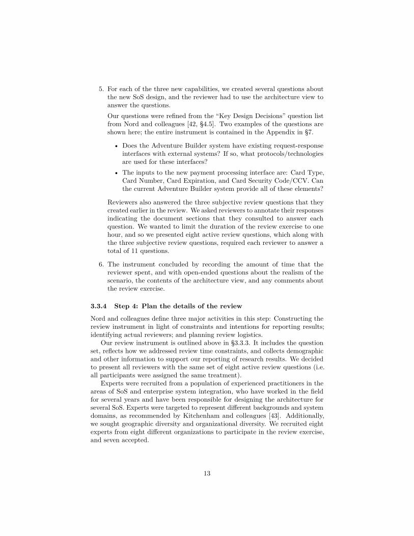
Concerns about resource sharing are addressed in the metamodel defined inTable 13.
Concerns about deployment of software onto computers and networks areaddressed in the metamodel defined in Table 14.
6.6 Correspondence rulesThere are no specific correspondence rules for the models constructed using thisviewpoint.
22

Table 9: Constituent System Stakeholders/Concerns Metamodel
Name: Constituent System Stakeholders/Concerns
Type: Allocation
Elements: Constituent system stakeholdersStakeholder concerns about system architecture
Relations: A stakeholder has a concern
Constraints: Stakeholders can have multiple concerns.Multiple stakeholders can have the same concern.
What’s it for: Aids in understanding the scope of the constituent system, andwho will be impacted by changes made to the constituent systemto allow it to join the SoS.
AddingAssumptions:
List any stakeholders that were considered but intentionallyexcluded.Note concerns that were identified but not addressed by thearchitecture.
Notations: List—one item per stakeholder, with list of concerns.Matrix—one row per stakeholder, one column per unique concern,“x” at row-column intersection means that the stakeholder inthat row has the concern in that column
6.7 Operations on views6.7.1 Creating a view of a constituent system using this viewpoint
In some cases, the information needed to create a view using this viewpointalready exists in the architecture documentation for the constituent system.Table 15 and Table 16 map the information required for this viewpoint to sourcesin two commonly used documentation frameworks: Views and Beyond [7], andDoDAF [10].
6.7.2 Interpretive, Analysis, and Design Methods
These operations on a view created from this viewpoint are discussed in the“What’s it for” section of the metamodels specified above.
6.8 Examples and NotesThe evaluation instrument in §7 provides an example of applying this viewpointto create a view on a constituent system.
23

Table 10: Constituent System Execution Time Context Metamodel
Name: Constituent System Execution Time Context
Type: Component and Connector
Elements: Running systemExternal software that the system interacts with
Relations: Any interaction at execution time (e.g., sends/receives message,call/return, reads/writes data, interrupts, synchronizes with)Property: Interfaces used for the interaction on self and externalsoftwareProperty: Direction of interaction (initiated by constituent sys-tem or external system)
Constraints: An interface on the constituent system may be used to interactwith multiple external systemsMultiple external systems may interact with the constituentsystem through the same interface on the constituent system
What’s it for: Aids in understanding the scope of the constituent system toanalyze the impacts of necessary or desired changesIdentifying viable SoS subsets and activity sequencing duringSoS integration
AddingAssumptions:
Startup behavior should be documented, using a notation suchas a message sequence diagramMonitoring and performance measurement behavior should bedocumented, using notations such as message sequence diagramsand state transition diagrams.
Notations: Diagram—e.g., Context Diagram from Clements [7]List—one item per constituent system interface, with list of ex-ternal systems and interfaces that it interacts withMatrix—rows are interfaces on the constituent system, columnsare interfaces on external systems, “S” at a row-column intersec-tion means that the constituent system interface sends an inter-action to the external system, “R” means that the constituentsystem interface receives an interaction from the external system
24

Table 11: Constituent System Code Context Metamodel
Name: Constituent System Code Context
Type: Module
Elements: Constituent system softwareExternal modules (libraries, packages, development tools, etc.)that the constituent software depends on
Relations: UsesProperties: type of dependency (e.g., code generation, build, unittest, integration test), version identification or key features usedfor external modules, source of external modules (e.g., FOSS,COTS, GOTS)
Constraints: Many-to-many
What’s it for: Aids in understanding the scope of the constituent system toanalyze the impacts of necessary or desired changes.Identifying mismatches among external dependencies that willconstrain deployment decisions or interactions among constituentsystems in the SoS.
AddingAssumptions:
What evolution is assumed for the external modules? Are therenew features or capabilities that are expected to be availablethat the constituent system will use?
Notations: Diagram—e.g., Uses Context Diagram from Clements [7]ListMatrix—This structure may be documented in a DependencyStructure Matrix generated for static analysis of the constituentsystem code.
25

Table 12: Constituent System Interface Information Metamodel
Name: Constituent System Interface Information Model
Type: Module
Elements: Information elements of interest to the SoS (e.g., a SoS that dealswith geo-location might have concepts like position, elevation,and direction)Information elements in the constituent system software archi-tectureProperties: Should include units, timeliness, precision, securitylevel, etc., as applicable
Relations: Between SoS and constituent system information elements, andfrom constituent system elements to sub-elements (to refinedetails).Logical associations (1-1, 1-n, n-m)Specialization/generalization (is-a)Aggregation
Constraints: None
What’s it for: Understanding how common concepts in the SoS are representedin a constituent system, and identifying mismatch between rep-resentations among constituent systems in the SoS
AddingAssumptions:
Explicitly identify SoS information elements that have no rela-tionship to the constituent system
Notations: Logical data modeling notations (ERD, UML)
26
Table 13: Shared Resource Metamodel
Name: Shared Resource
Type: Component and Connector
Elements: Component(s) representing a resource that is used by the con-stituent system and by other external systems. These includeprocessor computing cycles, memory, disk space, network inter-faces, network bandwidth, files, databases or repository, virtualinfrastructure, and system physical resources such as a display,radio frequency, or antenna.Component(s) in the constituent system that use the sharedresource
Relations: Any interaction during execution that acquires, consumes, orreleases the shared resource.
Constraints: None
What’s it for: Analyzing capacity and performance/availability of the SoS. Iden-tifying cases of undesirable SoS behavior due to mismatch be-tween resource sharing approaches of constituent systems.
AddingAssumptions:
Is the resource explicitly or implicitly acquired and released?What is the behavior if insufficient (or no) resources are available?
Notations: Static diagrams—e.g., from Views and Beyond component andconnector style guide [7]Behavior diagrams—message sequence charts, state transitiondiagrams, etc.
27

Table 14: Deployment Metamodel
Name: Deployment
Type: Allocation
Elements: Software units of execution, with properties that specify theexecution needs and constraintsComputers and networks that execute software, with proper-ties that specify the execution resources (e.g., compute cycles,memory, storage, and bandwidth) provided
Relations: Software units execute on computers and networks.
Constraints: None
What’s it for: Analyzing performance and availability, and possibly securityand other qualities. Assessing operating cost (e.g., requiredhardware and software, operations staff skills).
AddingAssumptions:
Can any part of the execution environment be virtualized?What are the assumptions about the network’s ability to reachthe internet or particular resources on a private network?
Notations: Table—Rows are instances or types of software elements, columnsare instances or types of computers and networksDiagram—e.g., Deployment Diagram from Clements [7]
Table 15: Mapping from SoS Viewpoint Metamodels to Views and BeyondApproach
Viewpoint Meta-model Name
Source of information in a Views and Beyond ar-chitecture document
Constituent Sys-tem Stakehold-ers/Concerns
Information Beyond Views—Documentation Roadmap.Stakeholder/View Matrix (typically generated by the ar-chitect but not explicitly included in the architecturedocumentation).
Constituent SystemExecution Time Con-text
Context diagram from one of the component and con-nector views, e.g., client-server, SOA, pipe and filter, orpublish-subscribe.
Constituent SystemCode Context
Context diagram from a module uses view.
Constituent SystemInterface InformationModel
Interface documentation for externally-visible interfaces(from component and connector views), or a data modelview packet focused on externally-visible information ele-ments.
Shared Resource Component and connector view.
Deployment Deployment view primary presentation or context dia-gram.
28
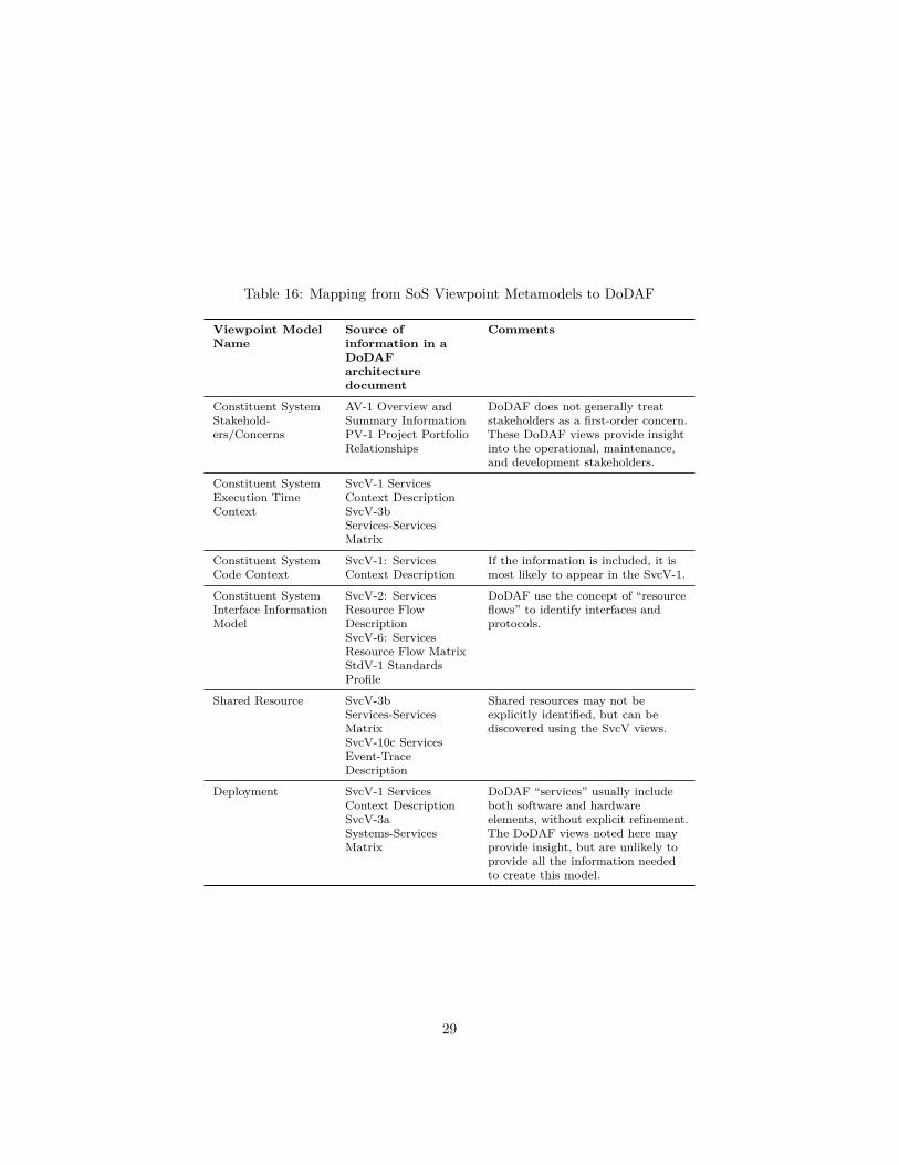
Table 16: Mapping from SoS Viewpoint Metamodels to DoDAF
Viewpoint ModelName
Source ofinformation in aDoDAFarchitecturedocument
Comments
Constituent SystemStakehold-ers/Concerns
AV-1 Overview andSummary InformationPV-1 Project PortfolioRelationships
DoDAF does not generally treatstakeholders as a first-order concern.These DoDAF views provide insightinto the operational, maintenance,and development stakeholders.
Constituent SystemExecution TimeContext
SvcV-1 ServicesContext DescriptionSvcV-3bServices-ServicesMatrix
Constituent SystemCode Context
SvcV-1: ServicesContext Description
If the information is included, it ismost likely to appear in the SvcV-1.
Constituent SystemInterface InformationModel
SvcV-2: ServicesResource FlowDescriptionSvcV-6: ServicesResource Flow MatrixStdV-1 StandardsProfile
DoDAF use the concept of “resourceflows” to identify interfaces andprotocols.
Shared Resource SvcV-3bServices-ServicesMatrixSvcV-10c ServicesEvent-TraceDescription
Shared resources may not beexplicitly identified, but can bediscovered using the SvcV views.
Deployment SvcV-1 ServicesContext DescriptionSvcV-3aSystems-ServicesMatrix
DoDAF “services” usually includeboth software and hardwareelements, without explicit refinement.The DoDAF views noted here mayprovide insight, but are unlikely toprovide all the information neededto create this model.
29

7 Appendix: Evaluation Instrument (includingexample use of the viewpoint)
This appendix contains the instrument used to evaluate the viewpoint, asdiscussed above in §3.3.3.
In order to construct the evaluation instrument, we had to use the viewpoint toconstruct system architecture documentation for the Adventure Builder System.The models were created in accordance with the viewpoint definition specifiedin §6, and so this also provides an example of the use of the viewpoint.
The evaluation instrument begins on the next page.
30

This is a role-playing exercise. You will play the role of an architect at afictitious company called “Social Travel”. Your business sells travel packages,and provides a number of social networking capabilities to allow your usersto connect and share information with each other. You are responsible for acollection of integrated enterprise systems:
• TravelPhotos:provides photo storage, tagging, and sharing with other SocialTravel users.
• TravelStuff : an online retailer for travel-related gear
• TravelIns: marketing travel insurance, such as trip cancellation coverage,international medical coverage, and emergency rescue/evacuation coverage.
• Enterprise-wide Social Features: a back-end system for cross-cutting fea-tures such as Profiles, Friends, Tags, Recommendations, Sharing, etc.
Your company has just acquired a smaller company called “Adventure Builder”that specialized in selling adventure travel packages. You need to integrate someof their systems with your enterprise systems, to realize three new capabilities:New Capability #1—Social featuresThis capability adds social features to Adventure Builder catalog browsing. Auser can see which trips her friends have taken, see comments about trips fromother users, see trip photos from other users, share plans and itineraries withfriends, etc.The architecture approach to achieve this capability will store the social datarepository (i.e. user profile, tags, sharing links, comments, etc.) outside of theAdventure Builder system. The Adventure Builder system must provide keys(or IDs) for data inside Adventure Builder that the social repository can link to.We also need to insert new widgets and elements into the customer UI to allowaccess to the social features.New Capability #2—Common payment processing interfaceThis capability changes the Adventure Builder payment processing interface touse the same interface as is used by the existing TravelStuff systems.The architecture approach to achieve this capability is to completely replaceAdventure Builder’s “Bank” interface.New Capability #3—Add cross-sell features This capability changes theAdventure Builder user interface to cross-sell products from TravelStuff andTravelIns when user books trip. For example, based on the destination, offerrelevant clothing products from TravelStuff and insurance from TravelIns againsta hurricane forcing the trip to be cancelled.The architecture approach to achieve this capability is to make a request toexisting SocialTravel cross-sell business logic trip with itinerary information,and then insert new widgets and elements into the customer UI to display thecross-sell offers.
In order to scope the work to develop these new capabilities, you needinformation about the Adventure Builder system. Below, please list threequestions that you have about the Adventure Builder system architecture. These
31

questions do not have to be the highest priority, or listed in any particular order.We are trying to understand how you approach this problem.
Your Questions:
Question 1:
Question 2:
Question 3:
32
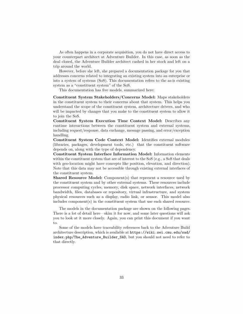
As often happens in a corporate acquisition, you do not have direct access toyour counterpart architect at Adventure Builder. In this case, as soon as thedeal closed, the Adventure Builder architect cashed in her stock and left on atrip around the world.
However, before she left, she prepared a documentation package for you thataddresses concerns related to integrating an existing system into an enterprise orinto a system of systems (SoS). This documentation refers to the as-is existingsystem as a “constituent system” of the SoS.
This documentation has five models, summarized here:
Constituent System Stakeholders/Concerns Model: Maps stakeholdersin the constituent system to their concerns about that system. This helps youunderstand the scope of the constituent system, architecture drivers, and whowill be impacted by changes that you make to the constituent system to allow itto join the SoS.Constituent System Execution Time Context Model: Describes anyruntime interactions between the constituent system and external systems,including request/response, data exchange, message passing, and error/exceptionhandling.Constituent System Code Context Model: Identifies external modules(libraries, packages, development tools, etc.) that the constituent softwaredepends on, along with the type of dependency.Constituent System Interface Information Model: Information elementswithin the constituent system that are of interest to the SoS (e.g., a SoS that dealswith geo-location might have concepts like position, elevation, and direction).Note that this data may not be accessible through existing external interfaces ofthe constituent system.Shared Resource Model: Component(s) that represent a resource used bythe constituent system and by other external systems. These resources includeprocessor computing cycles, memory, disk space, network interfaces, networkbandwidth, files, databases or repository, virtual infrastructure, and systemphysical resources such as a display, radio link, or sensor. This model alsoincludes component(s) in the constituent system that use each shared resource.
The models in the documentation package are shown on the following pages.There is a lot of detail here—skim it for now, and some later questions will askyou to look at it more closely. Again, you can print this document if you wantto.
Some of the models have traceability references back to the Adventure Buildarchitecture description, which is available at https://wiki.sei.cmu.edu/sad/index.php/The_Adventure_Builder_SAD, but you should not need to refer tothat directly.
33
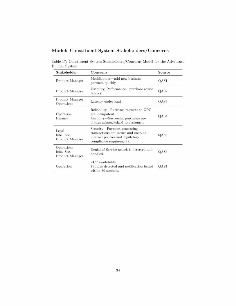
Model: Constituent System Stakeholders/Concerns
Table 17: Constituent System Stakeholders/Concerns Model for the AdventureBuilder System
Stakeholder Concerns Source
Product Manager Modifiability—add new businesspartners quickly QAS1
Product Manager Usability, Performance—purchase actionlatency QAS2
Product ManagerOperations Latency under load QAS3
OperationFinance
Reliability—Purchase requests to OPCare idempotent.Usability—Successful purchases arealways acknowledged to customer.
QAS4
LegalInfo. Sec.Product Manager
Security—Payment processingtransactions are secure and meet allinternal policies and regulatorycompliance requirements.
QAS5
OperationsInfo. Sec.Product Manager
Denial of Service attack is detected andhandled. QAS6
Operation24/7 availability.Failures detected and notification issuedwithin 30 seconds.
QAS7
34

Model: Constituent System Execution Time Context
Table 18: Constituent System Execution-Time Context Model for the AdventureBuilder System
ExternalSystem
Interfaces to the external systemand interface properties Source
BankInterface: CreditCardService/SOAP/Adventure Builderinvokes request
Top Level SOAView PrimaryPresentation
AirlineProvider
Interface: AirlinePOService/SOAP/Adventure Builderinvokes request Interface: Web Service
Broker/SOAP/Adventure Builderreceives request
Top Level SOAView PrimaryPresentation
LodgingProvider
Interface: LodgingPOService/SOAP/Adventure Builderinvokes request Interface: Web Service
Broker/SOAP/Adventure Builderreceives request
Top Level SOAView PrimaryPresentation
ActivityProvider
Interface: ActivityPOService/SOAP/Adventure Builderinvokes requestInterface: Web Service
Broker /SOAP/ Adventure Builderreceives request
Top Level SOAView PrimaryPresentation
User’s EmailClient
Interface: SMTP/SMTP/externalconfiguration file
Top Level SOAView PrimaryPresentation
Also, the top-level workflow diagram is applicable here to show how theseinterfaces are used in practice. This is shown in Fig. 2.
35

Figure 2: Workflow behavior diagram from Adventure Builder Architecture
36

Model: Constituent System Code Context
Table 19: Constituent System Code Context Model for the Adventure BuilderSystem
ExternalModule used byAB System
Properties Source
gwt (Google WebToolkit)
Dependency Type: Build (generatesJavascript for execution);Version unspecified;Open Source
Top LevelModule UsesDiagram
waf (WebApplicationFramework)
Dependency Type: Build?;Version “Java Blueprints”;Open Source
Top LevelModule UsesDiagram
wsdlsDependency: Build;Version unspecified;license unspecified
Top LevelModule UsesDiagram
37

Model: Constituent System Interface Information Model
Figure 3: Part 1 of Constituent System Interface Information Model for theAdventure Builder System (From Adventure Builder Data Model View)
38

Our approach for new capability #2 requires us to replace the Bank interface.Part of the information model for the Bank interface is shown in Fig. 4.
Table 20: Element Catalog for Part 1 of Interface Information ModelInformationElement Description
PurchaseOrder Aggregate of transportation, lodging, package, andactivity orders.
UserAccount An end user of the AdventureBuilder application. Westore email id, password, and contact info.
AirlineOrder Aggregate of purchased transportation entries.
Transportation
Each transportation entry is a flight available forbooking in our travel packages. For each one, we record:name, departure and arrival airports, days and times,airline name, flight number, rate, cabin class.
LodgingOrder Aggregate of purchased lodging entries.
LodgingA hotel, guesthouse or B&B that can be used for lodgingin our travel packages. For each type of lodging, we storename, description, location info, room description, rates.
Package
A travel package available in our catalog. A packagespecifies lodging and a list of activities. Attributes of apackage include name, description, rate per person,category and a representative image to show to the user.
Category
A category of adventure travel packages. Examples:island packages, mountain adventures. Thiscategorization helps the user to browse through ourcatalog of packages. Category data consists of a name,description and a representative image to show on theuser screen.
Activity
An adventure activity available. Examples: snorkeling,fishing, bird watching, rafting, surfing. Activities areavailable in selected packages. Information stored foreach activity include: name, description, rate, and arepresentative image to show to the user.
ActivityInPackageThis entity represents the many-to-many relationshipbetween activity and package. It simply lists theactivities in each package (“join table”)
ActivityPurchase-Order Aggregate of purchased activity entries (“join table”)
39

Type CreditCard// This type is used to store the credit card information of the user.String cardExpiryDateString cardNumberString cardType
Figure 4: Part 2 of Constituent System Interface Information Model for theAdventure Builder System
40

Model: Shared Resource ModelIn the stand-alone Adventure Builder system, there are no resources shared withany external systems.
In the new SoS, we have several resources that now will be shared. Theseare shown in Table 21. For each resource identified in Table 21, the source ofthe information in the Adventure Builder Architecture Documentation is shown.
Table 21: Shared Resource Model for the Adventure Builder System
ExternalResource
AdventureBuilder ResourceUsage
Resource sharedwith Source
BankInterface(accessedthroughFirewall)
Validate credit cardfor every customerpurchase(Call/Return)
OtherSocialTravel.comapplications(Call/Return)
OPC C&CView andDeploymentView
AdventureOrderProcessingDB (executeson srv-dbopc)
The OrderProcessingComponent uses thisfor consumer accountdata, consumerpurchases andexternal invoices(R/W)
Consumer Website(mostly read forauthentication, writeonly at accountcreation and update)Social features(read—need tocharacterizeworkload)Cross-sell(read—once perpurchase)
OPC C&CView andDeploymentView
Consumer UI(executes onsrv-web1 andsrv-web2)
Primary shop andpurchase workflows.
SocialFeatures—insert newcontent for tagging,sharing, etc.Cross-sell— insertcross-sell features.
Top LevelUses Viewand InstallView andDeploymentView
41

Now you are going to use the models provided in the view of the AB systemto answer some questions. We have a few questions related to each of the newcapabilities. Obviously, in a real integration project, there would be a multitudeof questions: Here, we attempt to cover a small sample of these questions toassess the utility of the models.
In each answer, please note which models you consulted to make your decision.If you cannot find sufficient information in the models to make your decision,please state this (these questions were formulated without consulting the models).
First, let’s consider our approach to achieving the first new capability: addingsocial features to the AB system. These social features will create runtimedependencies between the AB system and the Social Travel system.
Question Your Answer
1. The AB system has 7x24 availability.The Social Travel systems have had recentoutages, and there is ongoing work toimprove availability. Which ABstakeholders do you need to engage withto understand the AB availabilityrequirements?
2. You need to expose the social featuresin the AB web user interface, which usesgwt (Google Web Toolkit). The SocialTravel system uses V2.7.0 of the gwt.Which version does AB use?
3. Is there an external programmaticinterface to access the User Account andPurchase Order data elements?
Next, let’s consider the second new capability, which requires us to replacethe payment processing interface on the AB system. AB calls this interface the“Bank” interface.
Question Your Answer
4. The inputs to the new paymentprocessing interface are: Card Type, CardNumber, Card Expiration, and CardSecurity Code/CCV. Can the current ABsystem provide all of these elements?
5. Using the new payment processinginterface may impact the purchasecompletion latency of the AB system.Which stakeholders do you need to consultwith about the performance requirements?
42
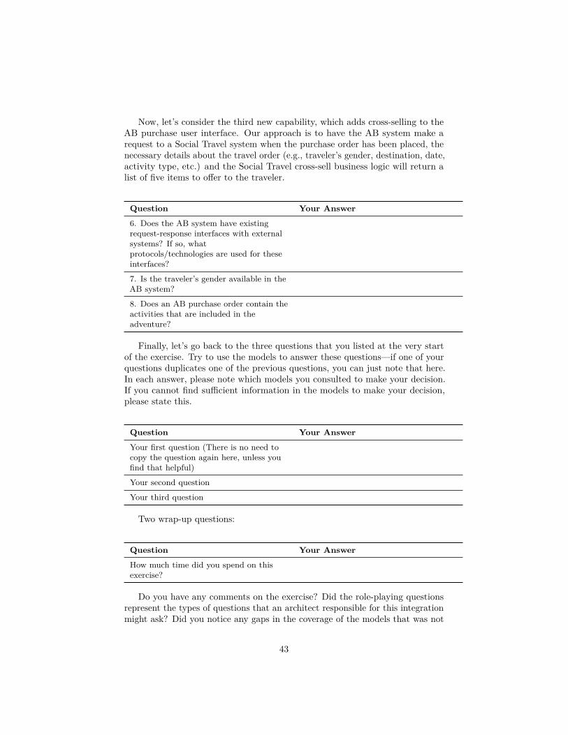
Now, let’s consider the third new capability, which adds cross-selling to theAB purchase user interface. Our approach is to have the AB system make arequest to a Social Travel system when the purchase order has been placed, thenecessary details about the travel order (e.g., traveler’s gender, destination, date,activity type, etc.) and the Social Travel cross-sell business logic will return alist of five items to offer to the traveler.
Question Your Answer
6. Does the AB system have existingrequest-response interfaces with externalsystems? If so, whatprotocols/technologies are used for theseinterfaces?
7. Is the traveler’s gender available in theAB system?
8. Does an AB purchase order contain theactivities that are included in theadventure?
Finally, let’s go back to the three questions that you listed at the very startof the exercise. Try to use the models to answer these questions—if one of yourquestions duplicates one of the previous questions, you can just note that here.In each answer, please note which models you consulted to make your decision.If you cannot find sufficient information in the models to make your decision,please state this.
Question Your Answer
Your first question (There is no need tocopy the question again here, unless youfind that helpful)
Your second question
Your third question
Two wrap-up questions:
Question Your Answer
How much time did you spend on thisexercise?
Do you have any comments on the exercise? Did the role-playing questionsrepresent the types of questions that an architect responsible for this integrationmight ask? Did you notice any gaps in the coverage of the models that was not
43

exposed by the questions? Do you have any comments about the utility of themodels in this viewpoint?
Your Answer:
This is the end of the exercise. Thank you for your contribution. Wewill share the results with you as soon as we complete the analysis.
44

References[1] M. W. Maier, Architecting principles for systems-of-systems, Systems En-
gineering 1 (4) (1998) 267–284. doi:10.1002/(SICI)1520-6858(1998)1:4<267::AID-SYS3>3.0.CO;2-D.
[2] J. Klein, S. Cohen, R. Kazman, Common platforms in system-of-systemsarchitectures: The state of the practice, in: Proc. IEEE/SMC Int. Conf. onSystem of Systems Eng., SoSE, 2013 [cited 1 Jan 2017].URL http://resources.sei.cmu.edu/library/asset-view.cfm?assetID=68315
[3] L. Northrop, P. Feiler, R. P. Gabriel, J. Goodenough, R. Linger,T. Longstaff, R. Kazman, M. Klein, D. Schmidt, K. Sullivan, K. Wallnau,Ultra-large-scale systems: The software challenge of the future, Tech. rep.,Software Engineering Institute, Carnegie Mellon University, Pittsburgh, PA(2006) [cited 1 Apr 2017].URL http://resources.sei.cmu.edu/library/asset-view.cfm?assetid=30519
[4] ISO/IEC/IEEE, ISO/IEC/IEEE 42010: Systems and software engineering -architecture description, Standard, ISO/IEC/IEEE (2011).
[5] D. L. Parnas, D. M. Weiss, Active design reviews: principles and practices,in: Proc. 8th Int. Conf. on Software Engineering, ICSE ’85, 1985, pp.132–136.
[6] R. J. Wieringa, Design Science Methodology for Information Systems andSoftware Engineering, Springer, Heidelberg, Germany, 2014.
[7] P. Clements, F. Bachman, L. Bass, D. Garlan, J. Ivers, R. Little, P. Merson,R. Nord, J. Stafford, Documenting Software Architectures: Views andBeyond, 2nd Edition, Addison-Wesley, 2011.
[8] N. Rozanski, E. Woods, Software Systems Architecture: Working WithStakeholders Using Viewpoints and Perspectives, Addison-Wesley, 2005.
[9] P. Kruchten, The Rational Unified Process: An Introduction, 3rd Edition,Addison-Wesley Professional, Boston, MA, USA, 2003.
[10] DOD Deputy Chief Information Officer, The DOD architecture frameworkversion 2.02, Standard, United States Department of Defense (2010) [cited18 Oct 2016].URL http://dodcio.defense.gov/Library/DoD-Architecture-Framework/
[11] Ministry of Defence, MOD architecture framework (2012) [cited 1 Jan 2017].URL https://www.gov.uk/guidance/mod-architecture-framework
45
[12] COMPASS. Comprehensive modelling for advanced systems of systems[online] (2014) [cited 1 June 2017].
[13] M. Guessi, V. V. G. Neto, T. Bianchi, K. R. Felizardo, F. Oquendo, E. Y.Nakagawa, A systematic literature review on the description of softwarearchitectures for systems of systems, in: Proc. 30th Ann. ACM Symp. onApplied Computing, SAC ’15, 2015, pp. 1433–1440. doi:10.1145/2695664.2695795.
[14] J. Brøndum, L. Zhu, Towards an architectural viewpoint for systems ofsoftware intensive systems, in: Proc. 2010 ICSE Workshop on Sharing andReusing Arch. Knowledge, SHARK ’10, 2010, pp. 60–63. doi:10.1145/1833335.1833344.
[15] M. Mori, A. Ceccarelli, P. Lollini, B. Frömel, F. Brancati, A. Bondavalli,Systems-of-systems modeling using a comprehensive viewpoint-based sysmlprofile, Journal of Software: Evolution and Process Early View (2017)e1878–n/a. doi:10.1002/smr.1878.
[16] E. Honour, DANSE–an effective, tool-supported methodology for systemsof systems engineering in Europe, in: Proc. 16th Ann. NDIA Systems Eng.Conf., National Defense Industry Association, 2013 [cited 1 June 2017].URL http://www.dtic.mil/ndia/2013/system/TH16282_Honour.pdf
[17] T. Bianchi, D. S. Santos, K. R. Felizardo, Quality attributes of systems-of-systems: A systematic literature review, in: Proc. 3rd Int. Workshop onSoftware Engineering for Systems-of-Systems, SESoS ’15, 2015, pp. 23–30.doi:DOI10.1109/SESoS.2015.12.
[18] J. Klein, H. van Vliet, A systematic review of system-of-systems architectureresearch, in: Proc. 9th Int. ACM SIGSOFT Conf. on the Quality of SoftwareArchitectures, QoSA’13, ACM, Vancouver, BC, Canada, 2013, pp. 13–22.doi:10.1145/2465478.2465490.
[19] T. Batista, Challenges for SoS architecture description, in: Proc. 1st Int.Workshop on Software Engineering for Systems-of-Systems, SESoS ’13, 2013,pp. 35–37. doi:10.1145/2489850.2489857.
[20] E. Silva, E. Cavalcante, T. Batista, F. Oquendo, F. C. Delicato, P. F. Pires,On the characterization of missions of systems-of-systems, in: Proc. of the2014 European Conf. on Software Architecture Workshops, ECSAW ’14,2014, pp. 26:1–26:8. doi:10.1145/2642803.2642829.
[21] E. Woods, N. Rozanski, The system context architectural viewpoint, in:Proc. Joint European Conf. on Software Arch. and Working IEEE/IFIPConf. on Software Arch., WICSA/ECSA’09, 2009, pp. 333–336. doi:10.1109/WICSA.2009.5290673.
46
[22] J. Bergey, J. Stephen Blanchette, P. Clements, M. Gagliardi, R. Wojcik,W. Wood, J. Klein, U.S. Army workshop on exploring enterprise, systemof systems, system, and software architectures, Tech. Rep. CMU/SEI-2009-TR-008, Software Engineering Institute, Carnegie Mellon University,Pittsburgh, PA (2009) [cited 1 Jan 2017].URL http://resources.sei.cmu.edu/library/asset-view.cfm?AssetID=9099
[23] ODUSD(A&T), Systems engineering guide for systems of systems, version1.0, Guide, US Department of Defense (2008).URL http://www.acq.osd.mil/se/docs/SE-Guide-for-SoS.pdf
[24] C. Benipayo, Understanding system interdependence to improve resilienceof shipboard cyber physical system, in: Proc. 19th Ann. NDIA SystemsEng. Conf., National Defense Industry Association, 2016 [cited 1 June2017].URL http://www.dtic.mil/ndia/2016/systems/18881_CaesarBenipayo.pdf
[25] V. Sitterle, Cross-scale resilience: Bridging system of systems andconsitituent systems engineering and analysis, in: Proc. 19th Ann. NDIASystems Eng. Conf., National Defense Industry Association, 2016 [cited 1June 2017].URL http://www.dtic.mil/ndia/2016/systems/18864_ValerieSitterle.pdf
[26] J. Gump, An architecture for agile systems engineering of secure commercial-off-the-shelf (COTS) mobile communications, in: Proc. 17th Ann. NDIASystems Eng. Conf., National Defense Industry Association, 2014 [cited 1June 2017].URL http://www.dtic.mil/ndia/2014/system/16845ThursTrack6Gump.pdf
[27] J. Manas, Test perspectives for architecture, in: Proc. 17th Ann. NDIASystems Eng. Conf., National Defense Industry Association, 2014 [cited 1June 2017].URL http://www.dtic.mil/ndia/2014/system/17006ThursTrack6Manas.pdf
[28] R. Carson, Differentiating system architectures, in: Proc. 17th Ann. NDIASystems Eng. Conf., National Defense Industry Association, 2014 [cited 1June 2017].URL http://www.dtic.mil/ndia/2014/system/16801ThursTrack6Carson.pdf
[29] N. Guertin, Capability based technical reference frameworks for opensystem architecture implementations, in: Proc. 17th Ann. NDIA SystemsEng. Conf., National Defense Industry Association, 2014 [cited 1 June
47

2017].URL http://www.dtic.mil/ndia/2014/system/16909ThursTrack6Guertin.pdf
[30] K. Baldwin, J. Dahmann, Sos considerations in the engineering of systems,in: Proc. 17th Ann. NDIA Systems Eng. Conf., National Defense IndustryAssociation, 2014 [cited 1 June 2017].URL http://www.dtic.mil/ndia/2014/system/16865ThursTrack2Baldwin.pdf
[31] M. Gagliardi, Identifying architectural challenges in system of systemsarchitectures, in: Proc. 16th Ann. NDIA Systems Eng. Conf., NationalDefense Industry Association, 2013 [cited 1 June 2017].URL http://www.dtic.mil/ndia/2013/system/TH16018_Gagliardi.pdf
[32] W. Pritchett, Application of a ground system architecture framework usingSysML, in: Proc. 16th Ann. NDIA Systems Eng. Conf., National DefenseIndustry Association, 2013 [cited 1 June 2017].URL http://www.dtic.mil/ndia/2013/system/W16096_Pritchett.pdf
[33] J. Dahmann, SoS pain points - INCOSE SoS working group survey, in:Proc. 15th Ann. NDIA Systems Eng. Conf., National Defense IndustryAssociation, San Diego, CA, 2012 [cited 27 Sep 2013].URL http://www.dtic.mil/ndia/2012system/ttrack214770.pdf
[34] J. Dahmann, R. Heilmann, SoS Systems Engineering (SE) and Test &Evaluation (T&E): Final Report of the NDIA SE Division SoS SE and T&ECommittees, in: Proc. 15th Ann. NDIA Systems Eng. Conf., NDIA, SanDiego, CA, 2012 [cited 27 Sep 2013].URL http://www.dtic.mil/ndia/2012system/ttrack214771.pdf
[35] J. Smith, P. Place, M. Novakouski, D. Carney, Examining the role of contextin data interoperability, in: Proc. 14th Ann. NDIA Systems Eng. Conf.,National Defense Industry Association, San Diego, CA, 2011 [cited 27 Sep2013].URL http://www.dtic.mil/ndia/2011system/13101_SmithWednesday.pdf
[36] J. A. Lane, J. Dahmann, G. Rebovich, R. Lowry, Key system of systemsengineering artifacts to guide engineering activities, in: Proc. 13th Ann.NDIA Systems Eng. Conf., National Defense Industry Association, SanDiego, CA, 2010 [cited 27 Sep 2013].URL http://www.dtic.mil/ndia/2010systemengr/WednesdayTrack3_10806Lane.pdf
[37] L. Bass, P. Clements, R. Kazman, Software Architecture in Practice, 3rdEdition, Addison-Wesley, 2013.
48

[38] T. Dyba, T. Dingsoyr, G. K. Hanssen, Applying systematic reviews todiverse study types: An experience report, in: Proc. 1st Int. Symp. onEmpirical Software Eng. and Measurement, ESEM 2007, 2007, pp. 225–234.doi:10.1109/ESEM.2007.59.
[39] M. A. P. M. van den Bosch, M. E. van Steenbergen, M. Lamaitre, R. Bos,A selection-method for enterprise application integration solutions, in: Proc.9th Int. Conf. on Business Informatics Research, BIR 2010, 2010, pp. 176–187. doi:10.1007/978-3-642-16101-8_14.
[40] S. Beecham, T. Hall, C. Britton, M. Cottee, A. Rainer, Using an expert panelto validate a requirements process improvement model, Journal of Systemsand Software 76 (3) (2005) 251–275. doi:10.1016/j.jss.2004.06.004.
[41] C. Hakim, Contemporary Social Research: 13, Routledge, London, UK,1987, Ch. Research Design: Strategies and Choices in the Design of SocialResearch.
[42] R. Nord, P. C. Clements, D. Emery, R. Hilliard, A structured approachfor reviewing architecture documentation, Technical Note CMU/SEI-2009-TN-030, Software Engineering Institute, Pittsburgh, PA (December 2009)[cited 22 Dec 2013].URL http://resources.sei.cmu.edu/library/asset-view.cfm?assetID=9045#
[43] B. A. Kitchenham, L. Pfleeger, L. M. Pickard, P. W. Jones, D. C. Hoaglin,K. E. Emam, J. Rosenberg, Preliminary guidelines for empirical researchin software engineering, IEEE Trans. Softw. Eng. 28 (8) (2002) 721–734.doi:10.1109/TSE.2002.1027796.
[44] E. R. Poort, H. van Vliet, RCDA: Architecting as a risk- and cost manage-ment discipline, Journal of Systems and Software 85 (9) (2012) 1995–2013.doi:10.1016/j.jss.2012.03.071.
[45] P. Runeson, M. Höst, Guidelines for conducting and reporting case studyresearch in software engineering, Empirical Software Engineering 14 (2)(2009) 131–164. doi:10.1007/s10664-008-9102-8.
[46] R. Yin, Case Study Research: Design and Methods, 3rd Edition, AppliedSocial Research Methods Series, Sage Publications, 2003.
49