system modelling - opencoursehub.cs.sfu.ca20-3-16 3 system modelling system modelling: – each...
TRANSCRIPT

20-3-16 1
System ModellingChapter 5.1 - 5.5Slides #12
CMPT 276 © Dr. B. FraserBased on slides from Software Engineering 9th ed, Sommerville.

20-3-16 2
Topics
1) Why model a system?
2) How can we model...a) the context of a system?
b) the interactions with the system?
c) the structure of a system?
d) the behaviour of a system?
3) Can we use models to generate a system?

20-3-16 3
System modelling
● System modelling:
– each model shows a..
● Usually models are graphical, Unified Modelling Language (UML).
● Modelling leaves out details:– Challenge is including
only the right details.

20-3-16 4
System perspectives
● Many perspectives of same systemCouch Ex: Concept art, design sketch, blueprint, assembly diag. etc.
● External perspective: – model the (context) where system is used.
● Interaction perspective: – model the interactions between
..
● Structural perspective: – model of a system or structure of its data.
● Behavioural perspective: – model the dynamic behaviour of the system and how it
..

20-3-16 5
Context models(Section 5.1)

20-3-16 6
Context models
● Context models: ..
– Show other systems which use or are used by the new system.
– Does not show the nature of the relationships: "who uses whom?"
● Position of the system boundary has a..on system requirements.
– political judgment
Ex: Electric Car’s Central processor

20-3-16 7
Interaction models(Section 5.2)

20-3-16 8
“Use-Case” modelling
● Each use-case represents..
● Use-case shows a very high-level view– Actors (stick-figures): people or other systems.
– Actions (ellipses): the interaction.
● Can complete the model with a..of the interaction.
● Does not show sequence of actions.

20-3-16 9
Order Out Pizza Use-Case Diagram
Note: The system being developed..

20-3-16 10
Use-Case Exercise: CourSysDraw a UML Use-Case diagram of CourSys for the following:Actions: Grade submission, Submit, Configure class, View gradeUsers: Student, Instructor, TA, Admin

20-3-16 11
Structural models

20-3-16 12
Structural models
● Structural models of software: ..
● Static Structural model– ..
Ex: Classes
● Use structural models of a system when discussing and designing the system architecture.
20-3-16 13
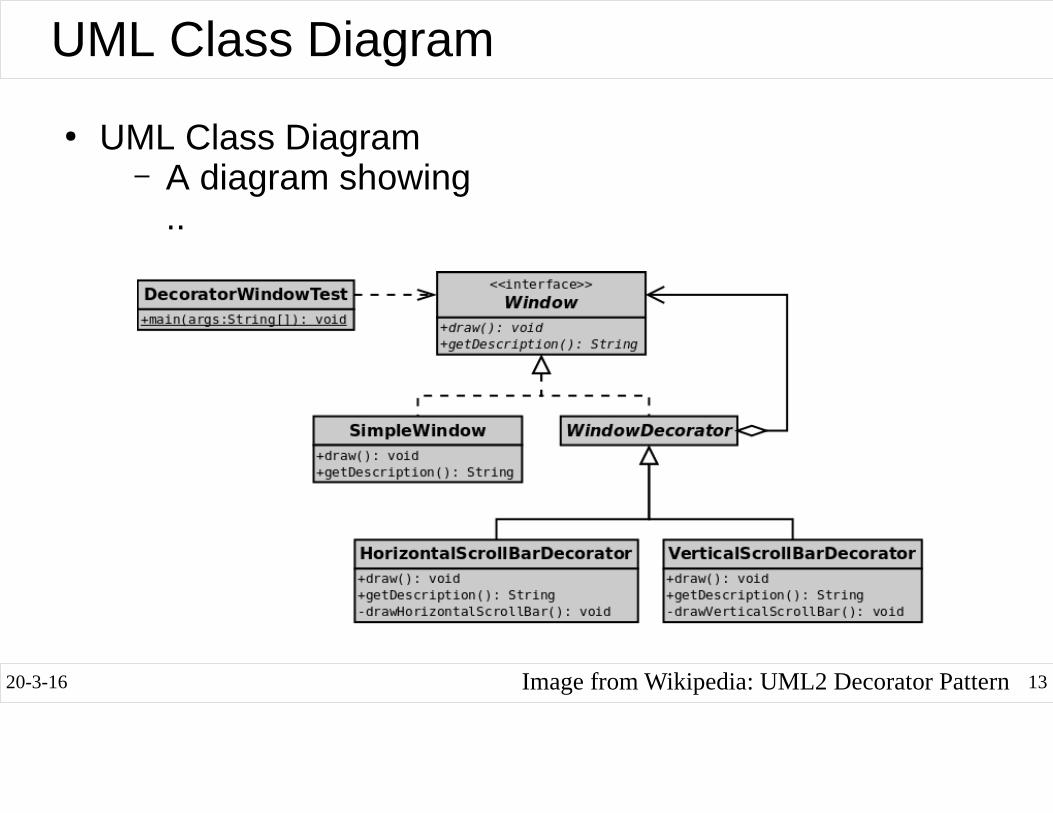
UML Class Diagram
● UML Class Diagram– A diagram showing
..
Image from Wikipedia: UML2 Decorator Pattern

20-3-16 14
Relationships: Aggregation
● Aggregation:..– Shows an object composed of other objects.
Ex: A cell-phone has-a screen, or has many buttons.
● Show number: 1, 0..1, *
● Hint:– This is usually for ..

20-3-16 15
Relationship: Dependency● Dependency:
Class X depends on class Y if..
– Usually said: “X uses Y”
– If X knows of Y's existence, then..
– ..
– Hint: Usually for..
● Example:class PizzaOrder {
private List<Pizza> pizzas;// ...public void slicePizzas() {
Slicer slicer = new Slicer();slicer.slicePizzas(pizzas);
}}

20-3-16 16
Relationships: Inheritance
● Inheritance:
– A cell-phone is a type of phone: cell-phone inherits from phone.
–
pointing from the subclass to the superclass (more general class).

20-3-16 17
Exercise: Label the relationships
«interface»

20-3-16 18
Exercise: UML Class Diagram● Draw the UML class diagram for the following Java code:
(Draw on next slide)class Phone {}
class SimCard {}class SimEjectorTool{}
class Battery {}class LiPoBattery extends Battery{}class LithiumIonBattery extends Battery {}
class CellPhone extends Phone{private Battery battery;private SimCard card;
void changeSimCard(SimCard card, SimEjectorTool tool) {}void setBattery(Battery battery) {}int countInstalledApps()
}

20-3-16 19
Draw UML Class Diagram Here

20-3-16 20
Behavioural models

20-3-16 21
Behavioural models
● Behavioural models: ..
● Real-time systems are often event-driven, with minimal data processing.
– Ex: microwave oven, alarm clock, etc.
● Event-driven modelling shows how a system..
– System has states, and events (stimuli) cause...
– Called state diagram, or FSM: Finite state machine.

20-3-16 22
System authentication diagram

20-3-16 23
State Machines
● What are each of the following state machines for?
http://www.uml-diagrams.org/examples/state-machine-example-water.png http://cphacker0901.wordpress.com/1900/01/01/android-power-management/

20-3-16 24
Android
● Many events can occur in the lifetime of an Android activity.
● Trace the following:– Creation
– While running, switch to home screen.
– While in background, killed by OS.
DEMO: LifeCycleDemo

20-3-16 25
..
..
..
..
UML State Diagram Components
Hot
Cold
Turn on green light
Warm
Error
Sound alarm
Cancelbutton
End
Coolbutton
Heatbutton
Coolbutton
After1 min
Greenbutton
State diagram for the Acme “Arbitrary Widget”
ShutdownAfter10s

20-3-16 26
Exercise: Boss-Fight State Diagram● Imagine you are in a game battling an epic dragon. Draw a
state diagram for the “Boss”.– Ground Phase: Dragon on ground (start).
● After 1 minute goes to air phase.
– Air Phase: Dragon in air, summons a minion.
● After minion is killed, go to ground phase.
– Burn Phase:
● When boss’s health reaches 30% he lands and starts breathing fire.
– Tamed: Boss at 0% health, players have tamed the dragon.
– Enraged:
● After 5 minutes, dragon heals fully, takes to the air and enrages killing everyone.
– Boss Win: If all players die.

20-3-16 28
Draw State Diagram Here
20-3-16 29
Model-driven engineering

20-3-16 30
Model-driven engineering
● Model-driven engineering– An approach to software development where
models rather than programs are the principal outputs of the development process.
–
● Pros– Work at...
– Cheaper port to new platforms: code is generated!
● Cons– Models for abstraction not always suited to
implementation.
–

20-3-16 31
Model-driven engineering example
● StarUML Generates C++ code from class diagram
– Generates all .h files and function stubs in .cpp files.
● Umple is for Java.
// Generated by StarUML(tm) C++ Add-In//// @ Project : Untitled// @ File Name : Zoo.h// @ Date : 20/02/2014// @ Author :
#if !defined(_ZOO_H)#define _ZOO_H
class Zoo {public:
void listAnimals();int getId();string getName();
private:string name;int id;
};
#endif //_ZOO_H

20-3-16 32
Summary● Model: abstract view of system; ignores some details
● System’s context– Context models show environment around system
● Interactions– Use cases - external actor interactions with system
● Structural models show system architecture– Class Diagrams shows static structure of classes
● Behavioural models - dynamic behaviour of executing system.
– State Diagram - states and internal/external events
● Model-driven engineering: build the model, and then tools automatically transformed to executable code.