system - konica minolta...enters digital output signals into the image processing device . the...
TRANSCRIPT

Operation Manual
EN 08A4T4BA01EN08
2015-09-04(SE)
AeroDR Portable UF UnitSYSTEM
DIRECT DIGITIZER


3
Contents
Introduction . . . . . . . . . . . . . . . . 5Introduction . . . . . . . . . . . . . . . . . . . . . . . . . . . . . . 6
Summary of usability specifications (for IEC/EN 60601-1-6, IEC/EN 62366) . . . . . . . 7Disclaimer . . . . . . . . . . . . . . . . . . . . . . . . . . . . . . 7Trademark . . . . . . . . . . . . . . . . . . . . . . . . . . . . . 8Term description . . . . . . . . . . . . . . . . . . . . . . . . . 8Structure of pages . . . . . . . . . . . . . . . . . . . . . . . 9
Chapter 1Safety Precautions & Warnings . . . . . . . . . . . . . . . . . 11
1 .1 Symbols relating to safety . . . . . . . . . . . . 121 .1 .1 Safety alert symbol . . . . . . . . . . . . . . 121 .1 .2 Warning notice (signal words) . . . . . . 121 .1 .3 Description of graphic symbols . . . . . 12
1 .2 Warning labels . . . . . . . . . . . . . . . . . . . . . 131 .2 .1 AeroDR Portable UF Unit . . . . . . . . . . 131 .2 .2 Mount kits . . . . . . . . . . . . . . . . . . . . . . 14
1 .3 Safety precautions . . . . . . . . . . . . . . . . . . 151 .3 .1 Precautions before usage . . . . . . . . . 151 .3 .2 Precautions for usage . . . . . . . . . . . . 151 .3 .3 Precautions regarding
electromagnetic waves . . . . . . . . . . . 171 .3 .4 Precautions regarding wireless
communication . . . . . . . . . . . . . . . . . . 211 .3 .5 Precautions for installing, moving,
and storing . . . . . . . . . . . . . . . . . . . . . 211 .3 .6 Precautions regarding maintenance . 211 .3 .7 Precautions on service life . . . . . . . . . 22
Chapter 2Product Overview . . . . . . . . . . 23
2 .1 Overview of the AeroDR Portable UF Unit . . . . . . . . . . . . . . . . . . . . . . . . . . . . . 24
2 .1 .1 Functions . . . . . . . . . . . . . . . . . . . . . . 242.1.2 System configuration . . . . . . . . . . . . . 24
2 .2 Component names and functions . . . . . . 262 .2 .1 AeroDR Portable UF Unit . . . . . . . . . . 262 .2 .2 AeroDR Portable Unit Battery . . . . . . 272 .2 .3 AeroDR Portable UF Detector
Charger Kit . . . . . . . . . . . . . . . . . . . . . 28
Chapter 3General Operations . . . . . . . . . 29
3 .1 Startup and shutdown . . . . . . . . . . . . . . . 303 .1 .1 Startup of each system device . . . . . . 303 .1 .2 Shutdown of each system device . . . 31
3 .2 Operations on the AeroDR Portable UF Unit . . . . . . . . . . . . . . . . . . . . . . . . . . . . . 32
3 .2 .1 Preparation to take radiography . . . . . 323 .2 .2 Exposure . . . . . . . . . . . . . . . . . . . . . . 333 .2 .3 Operations after radiography . . . . . . . 343 .2 .4 Mounting or dismounting the
AeroDR Portable Unit Battery . . . . . . 353 .2 .5 Operating the mount kit . . . . . . . . . . . 373 .2 .6 Precautions of operations . . . . . . . . . 38
3 .3 Recharging of the AeroDR Portable Unit Battery . . . . . . . . . . . . . . . . . . . . . . . . . . . 41
3 .3 .1 Recharging . . . . . . . . . . . . . . . . . . . . . 413 .3 .2 When recharging the battery with the
AeroDR Portable UF Unit inserted in the X-ray device . . . . . . . . . . . . . . . . . 42
3 .3 .3 Charging time guide . . . . . . . . . . . . . . 433 .3 .4 Charging indication . . . . . . . . . . . . . . 43
3 .4 Operations on the AeroDR Portable UF Detector Charger Kit . . . . . . . . . . . . . . . . 44
3 .4 .1 Preparation . . . . . . . . . . . . . . . . . . . . 443 .4 .2 Recharging of the AeroDR Detector . 453 .4 .3 Operations after recharging the
AeroDR Detector . . . . . . . . . . . . . . . . 453 .4 .4 Storing Panel Charge Cable . . . . . . . 46
Chapter 4Status (LED) Display . . . . . . . . 47
4 .1 LED display of respective devices . . . . . . 484 .1 .1 AeroDR Portable UF Unit . . . . . . . . . . 484 .1 .2 AeroDR Portable Unit Battery . . . . . . 48
Contents
4
Chapter 5Troubleshooting . . . . . . . . . . . 49
5 .1 Various problems and countermeasures . 505 .1 .1 AeroDR Portable UF Unit . . . . . . . . . . 505 .1 .2 AeroDR Portable UF Detector
Charger Kit . . . . . . . . . . . . . . . . . . . . 51
Chapter 6Maintenance . . . . . . . . . . . . . . . 53
6 .1 Maintenance and inspection items . . . . . 546 .1 .1 Maintenance schedule . . . . . . . . . . . . 546 .1 .2 Cleaning . . . . . . . . . . . . . . . . . . . . . . . 546 .1 .3 Periodical replacement parts . . . . . . . 55
Chapter 7Specifications . . . . . . . . . . . . . 57
7.1 Specifications . . . . . . . . . . . . . . . . . . . . . 587 .1 .1 AeroDR Portable UF Unit . . . . . . . . . . 587 .1 .2 AeroDR Portable Unit Battery . . . . . . 597 .1 .3 AeroDR Portable UF Detector
Charger Kit . . . . . . . . . . . . . . . . . . . . . 597 .1 .4 General AeroDR Portable UF Unit . . . 607.1.5 Product configuration . . . . . . . . . . . . . 60
5
Introduction
6
Introduction
The Direct Digitizer AeroDR System picks up an X-ray image of human body using the X-ray planar detector, and enters digital output signals into the image processing device . The system then acquires this image as diagnostic im-age data using the digital image acquisition device, and transfers the image data to the filing system, the printer, the image display unit and others . Especially, the AeroDR Portable UF Unit can be combined with a X-ray device, and used as a portable radiography unit anywhere inside hospital facilities .Note that the Direct Digitizer AeroDR System can be used for radiography diagnosis, but not for mammography .
The AeroDR Detector, AeroDR Interface Unit, AeroDR Battery Charger, and the DIRECT DIGITIZER CS-7 or Image-Pilot (hereafter referred to as the image processing controller), which controls the receiving, processing, and output of image data of this device, are required for the operation of AeroDR Portable UF Unit . For the operation of the im-age processing controller, refer to the "Operation Manual" of the image processing controller .
This Operation Manual describes the basic functions of AeroDR Portable UF Unit so that you or the operator of this unit can understand the basic unit functions. When you use the AeroDR Portable UF Unit for the first time, be sure to read this manual and start the actual operation . Also, after you have read this manual, keep this manual close to the AeroDR Portable UF Unit and use it as a guidebook to operate the AeroDR Portable UF Unit in the best conditions .
* If the pages of the operation manual are smudged or illegible, replace it with a new one (Charged) .* Illustrations of X-ray device included in this manual are an example .
CAUTION
•The AeroDR Portable UF Unit can be used together with the AeroDR SYSTEM and AeroDR SYSTEM 2 .
•This manual collectively refers to both the AeroDR SYSTEM and AeroDR SYSTEM 2 as the "AeroDR SYSTEM" .
•Before using the AeroDR Portable UF Unit, carefully read the AeroDR System/AeroDR SYSTEM 2 Operation Manual and the image processing controller Operation Manual, and refer to the operation manuals for the AeroDR Access Point and any optional devices .
• In this manual, the AeroDR Interface Unit and the AeroDR Battery Charger are used in the examples . Replace the device names with the devices to be used .

7
Introduction
Summaryofusabilityspecifications(forIEC/EN60601-1-6,IEC/EN62366)
1) Medical purposes • Provision and reading of disease and injury diagnostic images .
2) Patient groups • No patient population exists who uses the device . • Patient population for the X-ray images read is not specified.
3) Parts of body or organizations to which the device is mounted or that interact with the device . • The AeroDR Portable UF Unit comes in contact with the skin of an operator .
4) Operating principle • The AeroDR Portable UF Unit is used together with the X-ray device which takes radiography . The built-in
AeroDR Access Point (wireless communication device) communicates with the AeroDR Detector and image processing controller .
• AeroDR Detector forms the still images according to the X-ray energy passing through human and animal bodies; after digitizing the exposed image, it is transmitted to the image processing controller console via the AeroDR Portable UF Unit by wireless communication .
• Connect the AeroDR Interface Unit to the AeroDR Detector using the AeroDR I/F Cable in order to recharge the AeroDR Detector and to register the AeroDR Detector used for the X-ray device .
• The AeroDR Battery Charger is used to recharge the AeroDR Detector and to register the AeroDR Detector used for the X-ray device .
• The image processing controller processes the image data into the diagnostic image, and then stores and outputs the images along with relevant patient information .
• The AeroDR Portable UF Unit connects to the AeroDR via the Panel Charge Cable and charges the AeroDR Detector while using the AeroDR Portable UF Detector Charger Kit .
5) Significant physical characteristics • Refer to "7.1 Specifications".
6) Significant performance characteristics • Refer to "2 .1 Overview of the AeroDR Portable UF Unit" .
7) User of this device • No special training is required to use this device . The intended users of this device are as follows .
A professional in good health with specialist knowledge/qualifications who has fully understood the content of this document . (Such as a doctor or radiological technologist)
Disclaimer
(1) This manual may not be reproduced in whole or in part without the permission of Konica Minolta, Inc .(2) The contents of this manual may be subject to change without prior notice .(3) Konica Minolta, Inc . is not responsible for any claims made for malfunction or damage caused by installation,
relocation, modification, maintenance, and repair made by anyone except Konica Minolta and contractors designated by Konica Minolta .
(4) Konica Minolta, Inc . is not responsible for any claims made for malfunction or damage to Konica Minolta products, caused by third-party products not installed by Konica Minolta .
(5) Konica Minolta, Inc . is not responsible for any claims made for malfunction or damage caused by maintenance and repair using maintenance parts other than those specified by Konica Minolta.
(6) Konica Minolta, Inc . is not responsible for any claims made for malfunction or damage caused by not observing the precautions and operation methods described in the operation manual .
(7) Konica Minolta, Inc . is not responsible for any claim for malfunction or damage of system units based on the environmental conditions that deviate from installation or application conditions of power supply and installation environment described in the Installation Requirements or Operation Manual .
(8) Konica Minolta, Inc . is not responsible for any claims for malfunction or damage caused by acts of nature such as fires, earthquakes, floods, or lightning strikes.
(9) Konica Minolta, Inc . is not responsible for any claims for malfunction or damage caused by using this device for any purpose other than that specified for this device.
(10) Diagnostic and treatment action is performed under the responsibility of the physician(s) . Konica Minolta, Inc . is not responsible for any diagnostic/treatment conditions or diagnostic/treatment results .

8
Introduction
Trademark
Company names and product names in this manual are trademarks or registered trademarks of their respective owners .Please note that ©, ® and ™ marks are omitted hereafter .
Copyright © 2011 - 2015 Konica Minolta, Inc . All Rights Reserved .
Term description
The meanings of terms used in this operation manual are as follows:
Terms Explanation
AeroDR Detector Collective term indicating AeroDR 1417HQ, AeroDR 1717HQ, AeroDR 1012HQ, AeroDR 2 1417HQ and AeroDR 2 1417S .
AeroDR Interface Unit It supplies the electric power to the AeroDR Detector when the AeroDR I/F Cable is used . Also, it has the hub function .
AeroDR Battery Charger It recharges the AeroDR Detector . Also, it has the registration function of AeroDR Detector .
AeroDR I/F Cable It connects between the AeroDR Detector and AeroDR Interface Unit . Also, it has the charging and registration functions of the AeroDR Detector .
Image processing controller The image processing workstation (CS-7 or ImagePilot) is referred to as the image processing controller .
9
Introduction
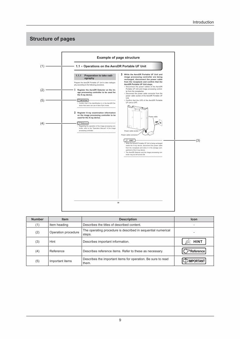
Structure of pages
200
3 While theAeroDRPortableUFUnitandimageprocessingcontroller arebeingrecharged,disconnect thepowercablefromthereceptacleandconfirmthattheAeroDRPortableUFUnitstops.• Disconnect thepowercablesof theAeroDRPortableUFUnitandimageprocessingcontrol-lerfromthereceptacles.
• Disconnectthepowercableconnectorfromthepowercablesocketof theAeroDRPortableUFUnit.
• Confirm that theLEDof theAeroDRPortableUFUnitisOFF.
Powercablesocket
Powercableconnector
Powercable
HINT • ••••••••••••••••••••••••••••••••••••
• WhiletheAeroDRPortableUFUnitisbeingrechargedinside theX-raydevice,disconnect thepowercablefromthereceptacleandstore it in thestoragecom-partmentoftheX-raydevice.
• TheAeroDRDetectorandtheimageprocessingcon-trollermaybeleftturnedON.
•••••••••••••••••••••••••••••••••••••••••••••••••••••
1.1.1 Preparationtotakeradi-ography
PreparetheAeroDRPortableUFUnit totakeradiogra-phyaccordingtothefollowingprocedure.
1 RegistertheAeroDRDetectoronthe im-ageprocessingcontroller tobeusedfortheX-raydevice.
IMPORTANT • ••••••••••••••••••••••••••••••••••••
• Confirmthat if the identification is in theAeroDRDe-tectorthatuserscanuseinAeroSyncmode.
•••••••••••••••••••••••••••••••••••••••••••••••••••••
2 RegisterX-rayexamination informationontheimageprocessingcontrollertobeusedfortheX-raydevice.
Reference • ••••••••••••••••••••••••••••••••••••
• Regardingtheoperationoftheimageprocessingcon-troller, refer to the"OperationManual"of the imageprocessingcontroller.
•••••••••••••••••••••••••••••••••••••••••••••••••••••
1.1●OperationsontheAeroDRPortableUFUnit
Exampleofpagestructure
(1)
(3)
(2)
(5)
(4)
Number Item Description Icon(1) Item heading Describes the titles of described content . -
(2) Operation procedure The operating procedure is described in sequential numerical steps . -
(3) Hint Describes important information . HINT
(4) Reference Describes reference items . Refer to these as necessary . Reference
(5) Important items Describes the important items for operation . Be sure to read them . IMPORTANT

10

11
Chapter 1Safety Precautions & Warnings
This chapter describes precautions and warnings
to ensure safe use of the AeroDR Portable UF Unit .

12
1 .1 Symbols relating to safety
1 .1 .1 Safety alert symbol
This is a "safety alert symbol" . This symbol alerts you to matters and/or operation potentially hazardous to yourself and other people . Read these messages and follow the instructions carefully .
1 .1 .2 Warning notice (signal words)
Signal words indicate the degree of potential hazards in the use of the product .Signal words include the following three types, which are used according to risk of damage caused by dan-ger and the severity of damage .
DANGERIndicates an imminently hazardous situation which, if not avoided, will result in death or serious injury .
WARNINGIndicates a potentially hazardous situation which, if not avoided, could result in death or serious injury .
CAUTIONIndicates a potentially hazardous situation which, if not avoided, could result in minor or moderate injury . It may also be used to indicate hazardous situation where only physical damage is likely to occur .
1 .1 .3 Description of graphic symbols
Indicates the Power On or Standby po-sition .
Indicates that it is necessary to read the Operation Manual before use or opera-tion of this device .
Indicates devices including radio fre-quency transmitters .
Indicates possibility of squeezing fingers in the moving part of the monitor fixture.
Indicates possibility of squeezing fingers in the moving part of the monitor fixture.
Indicates possibility of squeezing fingers in the moving part of the monitor fixture.
Indicates possibility of squeezing fin-gers .
Indicates that a load should not be placed on this device .
Indicates that items should not be placed on this device .
This CE mark on this product indi-cates that this product is in conformity with the applicable requirements set out in the Directive 93/42/EEC (Medi-cal Device Directive) and in Directive 2011/65/EU (RoHS Directive) .EC Directive 93/42/EEC does not cover animal use .

13
Chapter 1
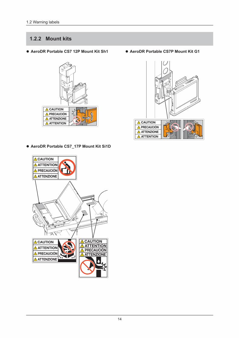
1 .2 Warning labels
Various warning labels are attached to the AeroDR Portable UF Unit and mount kits in locations shown below . Do not remove these labels from the AeroDR Portable UF Unit and mount kits .Warning labels are there to make sure that the user recognizes potential hazards when operating the AeroDR Por-table UF Unit and mount kits .
* If a warning label is too dirty or damaged to read, contact Konica Minolta technical representatives to have a new warning label attached, and redisplay by parts replacement . (There is a fee for this service .)
1 .2 .1 AeroDR Portable UF Unit
14
1 .2 Warning labels
1 .2 .2 Mount kits
z AeroDR Portable CS7P Mount Kit G1 z AeroDR Portable CS7 12P Mount Kit Sh1
z AeroDR Portable CS7_17P Mount Kit Si1D
15
Chapter 1
1 .3 Safety precautions
Read all safety precautions thoroughly before using the AeroDR Portable UF Unit .Be sure to observe the safety precautions described in this section .
CAUTIONBefore using the AeroDR Portable UF Unit, read the "Safety Warnings and Cautions" of the AeroDR SYSTEM/AeroDR SYSTEM 2 Operation Manual and be familiar with the unit handling precautions .
1 .3 .1 Precautions before usage
CAUTION• The operator (hospital or clinic) is responsible to the
usage and maintenance of the AeroDR Portable UF Unit . Any person other than the physician or other than certified person under law must not use this unit.
• The AeroDR Portable UF Unit is suitable to use outside of patient environment .
• Before using the AeroDR Portable UF Unit, check to see that the unit operates normally .
• If the AeroDR Portable UF Unit has failed, turn its power switch Off and place a warning tag showing the "Out of order" or others . Contact Konica Minolta technical representatives .
• As the AeroDR Portable UF Unit is not explosion-proof, do not use any flammable or an explosive gas near this unit .
• If you dispose the AeroDR Portable UF Unit, its ac-cessories, options, consumables, storage media and their packing materials, follow the applicable Waste Management Law (the Waste Disposal and Public Cleaning Law) and ask an authorized indus-trial waste disposal contractor for their disposal . For the disposal method, follow the applicable regula-tions and rules of local government .
This symbol means: Do not dispose of this product together with your household waste!
Please refer to the information of your local community or contact our dealers regarding the proper handling of end-of-life electric and electronic equipments .
Recycling of this product will help to conserve natural resources and prevent potential negative consequences for the environment and human health caused by inappropriate waste handling .
1 .3 .2 Precautions for usage
WARNING• Take note of the following when using the AeroDR
Portable UF Unit: - Do not subject the unit to strong shocks or ex-
cessive loads by dropping and others . - Do not disassemble or modify the unit . - Do not attach a third-party device (except for
those purchased from Konica Minolta) to this unit . - Do not turn the Power switch Off or unplug the
power cable from the receptacle when the sys-tem is operating .
- Take care not to drop the unit on the human body . - Do not use the unit when it is being charged or
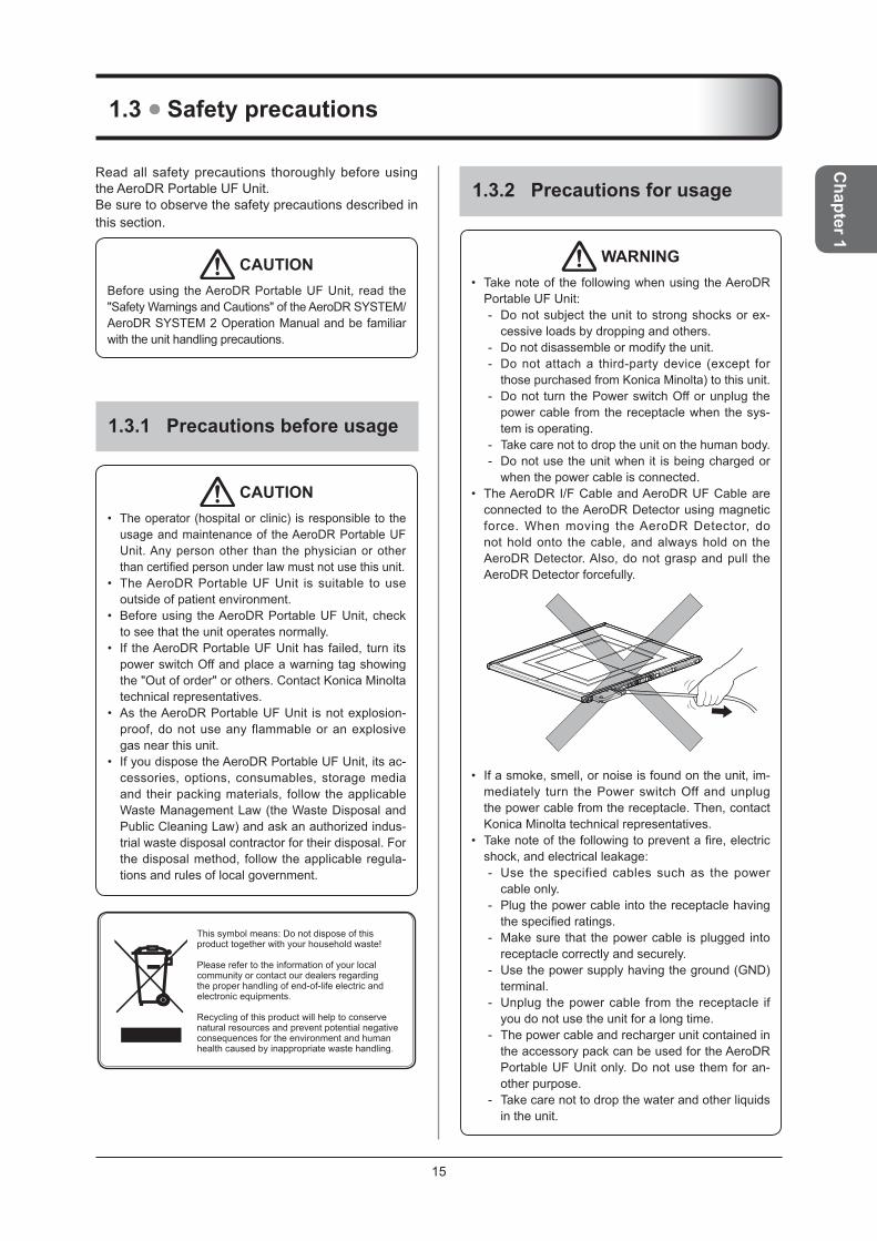
when the power cable is connected .• The AeroDR I/F Cable and AeroDR UF Cable are
connected to the AeroDR Detector using magnetic force . When moving the AeroDR Detector, do not hold onto the cable, and always hold on the AeroDR Detector . Also, do not grasp and pull the AeroDR Detector forcefully .
• If a smoke, smell, or noise is found on the unit, im-mediately turn the Power switch Off and unplug the power cable from the receptacle . Then, contact Konica Minolta technical representatives .
• Take note of the following to prevent a fire, electric shock, and electrical leakage:
- Use the specified cables such as the power cable only .
- Plug the power cable into the receptacle having the specified ratings.
- Make sure that the power cable is plugged into receptacle correctly and securely .
- Use the power supply having the ground (GND) terminal .
- Unplug the power cable from the receptacle if you do not use the unit for a long time .
- The power cable and recharger unit contained in the accessory pack can be used for the AeroDR Portable UF Unit only . Do not use them for an-other purpose .
- Take care not to drop the water and other liquids in the unit .

1 .3 Safety precautions
16
WARNING - Take care not to drop or insert foreign materials
such as metals and wires in the unit . - Do not allow any metal or conductive objects to
come into contact with the spring connector of the Panel Charge Cable .
- Do not handle the power plug with wet hands . - Take care to avoid contaminating the power plug
and Panel Charge Cable with dust and others . - Do not use extension cables . - Do not use the star-burst connection of power cables . - Take care not to damage the power cable and
Panel Charge Cable . Also, do not use the power cable if it is damaged .
- Do not connect a metal wire or other conductors to the terminal of AeroDR Portable Unit Batteries .
- Do not carry or store the AeroDR Portable Unit Batteries together with metallic items such as necklaces, hairpins, coins and keys .
• If the housing is deformed or cracked, stop using the unit immediately and contact Konica Minolta technical representatives .
• Register the AeroDR Detector using the AeroDR Bat-tery Charger, AeroDR Battery Charger2, AeroDR Interface Unit, or AeroDR Interface Unit2 which sup-ports the image processing controller to be used and the AeroDR Portable UF Unit . If an incorrect device is registered, the AeroDR Detector may be selected from another CS-7 .
• If the buzzer of AeroDR Portable UF Unit sounds (and the orange Power LED blinks), immediately stop the radiography and recharge the AeroDR Por-table Unit Batteries .
• Do not leave the AeroDR Portable Unit Batteries in a high temperature such as direct sunlight or a ve-hicle parking under the hot sun . If done, the battery fluid may leak.
• The AeroDR Portable Unit Batteries are consum-able parts . If the operation time of AeroDR Portable UF Unit has been shortened, replace the AeroDR Portable Unit Batteries with new ones .
• Take note of the following to prevent an overheating, an explosion, and a fire of AeroDR Portable Unit Batteries:
- Keep the batteries away from a heat source such as a space heater .
- Do not give a strong shock to the batteries by dropping them from height or others . Also, do not throw the batteries .
- Do not point a nail into batteries, do not hammer the batteries, and do not step on the batteries .
- Recharge the specified rechargeable batteries only.
CAUTION• Take note of the following when using the AeroDR
Portable UF Unit: - Do not use devices that emit electromagnetic
waves such as high-frequency therapy equipment, mobile phones, or pocket pagers, close to this unit .
- Take note of the reception status for radios and TVs near this unit, since an interference may oc-cur in them when this unit is in use .
- Use under the specified environmental condi-tions . Failure to do so may result in degradation of performance or malfunction of this unit .
- Do not recharge the AeroDR Detector using the AeroDR Portable UF Detector Charger Kit when an exposure is being carried out .
• When using the Panel Charge Cable, observe the following:
- Remove the cable by holding the connector housing .
- Do not let the cable get pinched by doors and do not place heavy objects on it .
- Do not bend or pull the cable excessively . - Make sure that the cable is properly connected
to the AeroDR Detector without wobbling . - Do not connect the connector housing back-
wards .• When the AeroDR Portable UF Unit is being
charged while stored in the X-ray device, do not move the X-ray device to another place .
• Take note of the following when handling the mount kit of the image processing controller:
- When moving the base, check to see that no person is around and move the base quietly .
- When moving the X-ray device, retract and se-cure the arm of the mount kit of the image pro-cessing controller .
- Take care not to bump your head and body to the arm .
- Take care as the mount kit of the image process-ing controller also moves when you move the arm of X-ray device .
- Do not lean on the device, and do not press it with force .
- Take care that your fingers and cables are not caught in the arm of the mount kit of the image processing controller .
1 .3 Safety precautions
17
Chapter 1
1 .3 .3 Precautions regarding electromagnetic waves
z EMC StatementThe AeroDR Portable UF Unit (called This Device) has been tested and found to comply with the IEC 60601-1-2: 2007 Standard .These limits are designed to provide reasonable pro-tection against harmful interference in a typical medi-cal installation . The device generates, uses and can radiate radio frequency energy and, if not installed and used in accordance with the instructions, may cause harmful interference to other devices in its vicinity . However, there is no guarantee that interference will not occur in a particular installation . Whether this device does cause harmful interference to other devices can be determined by turning this de-vice off and on . If it causes harmful interference, the user is encouraged to try to correct the interference by 1 or more of the following measures:• Reorient or relocate the receiving device .• Increase the separation between the devices .• Connect this device into a wall outlet on a circuit differ-
ent from that to which the other devices are connected .• Contact Konica Minolta technical representatives .
z Supplementary information regarding IEC 60601-1-2:2007
(1) Take precautions against this device especially regarding EMC . Install and put into service according to the electromagnetic compatibility (EMC) information provided in the manual (Table 1 - Table 4) .
(2) Do not use mobile phones or pocket pagers in the vicinity of this device . Use of mobile phones or pocket pagers near this device can cause errors in operation due to electromagnetic wave interference, so such devices should be turned off in the vicinity of this device .
(3) Cable list • Power cable (1 .8 m/3-Wire/Without shield; in-
cluded in the recharger unit package .) • Ethernet cable (max 20 m/With shield) • Panel Charge Cable (1 .5m; included in the
AeroDR Portable UF Detector Charger Kit .)(4) The use of accessories, transducers and cables
other than those sold by Konica Minolta, Inc . as internal components, may result in increased emissions or decreased electromagnetic immunity of this device .
(5) Do not use this device adjacent to or stacked with other devices . If adjacent or stacked use is necessary, confirm normal operation in the configuration in which this device will be used.
Normal operation has been checked when mounted on the X-ray device . For applicable X-ray devices, contact Konica Minolta technical representatives .
(6) Speci f icat ions regarding RF transmit ters frequency: • Frequency: 5150 to 5350 MHz, 5470 to 5850
MHz • Modulation: OFDM • Maximum effective radiation power: +15 dBm • This device may be interfered with by other de-
vices that conform to CISPR emission require-ments .

18
1 .3 Safety precautions
Table 1
Guidelines and manufacture's declaration - electromagnetic emissions
This device is intended for use in the electromagnetic environment specified below.The customer or the user of this device should assure that it is used in such an environment .
Emissions test Compliance Electromagnetic environment - guidelines
RF emissions
CISPR 11Group 1
The device uses RF energy only for its internal function . Therefore, its RF emissions are very low and are not likely to cause any interference in nearby electronic equipment .
RF emissions
CISPR 11Class B
This device is suitable for use in all establishments including the following:Domestic establishments and those directly connected to the public low-voltage power supply network that supplies buildings for domestic purposes .
Harmonic emissions
IEC 61000-3-2Class A
Voltage fluctuations/flicker emissions
IEC 61000-3-3
Complies
Table 2
Guidelines and manufacturer's declaration - electromagnetic immunity
This device is intended for use in the electromagnetic environment specified below.The customer or the user of this device should assure that it is used in such an environment .
Immunity test IEC60601testlevel Compliance levelElectromagnetic environment -
guidelinesElectrostatic discharge (ESD)
IEC 61000-4-2
± 6 kV contact ± 6 kV contactFloors should be wood, concrete or ceramic tile. If floors are covered with synthetic material, the relative humidity should be at least 30% . Mains power quality should be that of a typical com-mercial or hospital environment .
± 8 kV air ± 8 kV air
Electrical fast transient/burst
IEC 61000-4-4
± 2 kV for power supply lines
± 2 kV for power supply lines
± 1 kV for input/output lines
± 1 kV for input/output lines
Surge
IEC 61000-4-5
± 1 kV differential mode ± 1 kV differential mode Mains power quality should be that of a typical commercial or hospital environ-ment . ± 2 kV common mode ± 2 kV common mode
Voltage dips, short interruptions and voltage variations on power supply input lines
IEC 61000-4-11
<5% UT (>95% dip in UT) for 0 .5 cycle
<5% UT (>95% dip in UT) for 0 .5 cycle Mains power quality should be that of a
typical commercial or hospital environ-ment . If the user of the device requires continued operation during power mains interruptions, it is recommended that the device be powered from an uninterrupted power supply or a battery .
40% UT (60% dip in UT) for 5 cycles
40% UT (60% dip in UT) for 5 cycles
70% UT (30% dip in UT) for 25 cycles
70% UT (30% dip in UT) for 25 cycles
<5% UT (<95% dip in UT) for 5 sec
<5% UT (<95% dip in UT) for 5 sec
Power frequency (50/60 Hz) magnetic field
IEC 61000-4-8
3 A/m 3 A/m
Power frequency magnetic fields should be at levels characteristic of a typical lo-cation in a typical commercial or hospital environment .
[NOTE] UT is the AC mains voltage prior to application of the test level .
19
Chapter 1
1 .3 Safety precautions
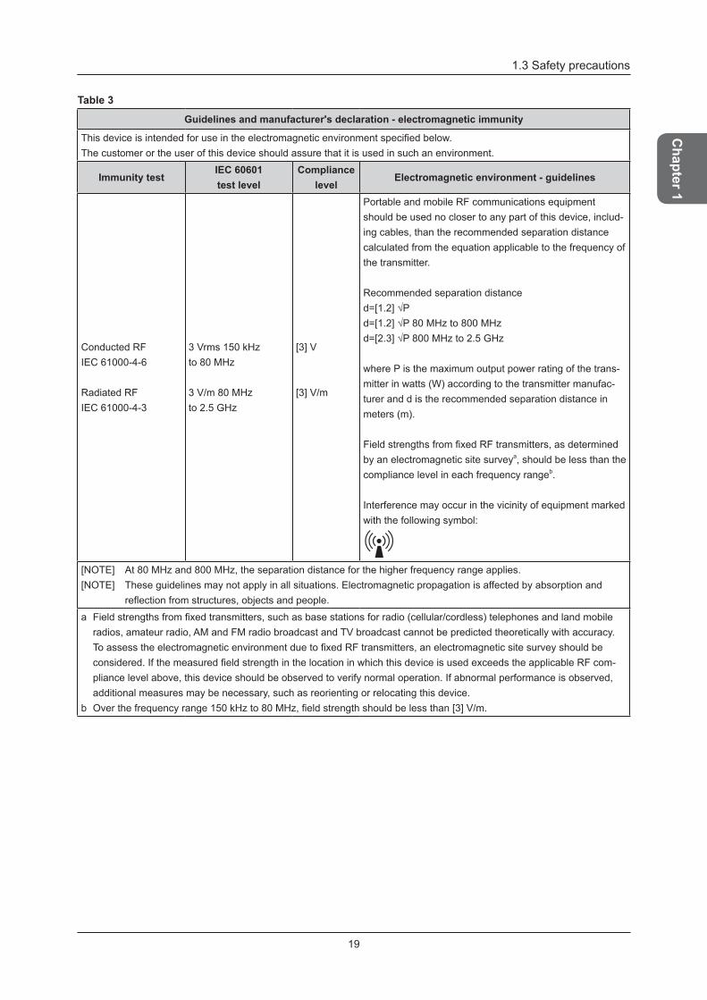
Table 3
Guidelines and manufacturer's declaration - electromagnetic immunity
This device is intended for use in the electromagnetic environment specified below.The customer or the user of this device should assure that it is used in such an environment .
Immunity testIEC60601 test level
Compliance level
Electromagnetic environment - guidelines
Conducted RFIEC 61000-4-6
Radiated RFIEC 61000-4-3
3 Vrms 150 kHzto 80 MHz
3 V/m 80 MHzto 2 .5 GHz
[3] V
[3] V/m
Portable and mobile RF communications equipment should be used no closer to any part of this device, includ-ing cables, than the recommended separation distance calculated from the equation applicable to the frequency of the transmitter .
Recommended separation distanced=[1.2] √Pd=[1.2] √P 80 MHz to 800 MHzd=[2.3] √P 800 MHz to 2.5 GHz
where P is the maximum output power rating of the trans-mitter in watts (W) according to the transmitter manufac-turer and d is the recommended separation distance in meters (m) .
Field strengths from fixed RF transmitters, as determined by an electromagnetic site surveya, should be less than the compliance level in each frequency rangeb .
Interference may occur in the vicinity of equipment marked with the following symbol:
[NOTE] At 80 MHz and 800 MHz, the separation distance for the higher frequency range applies . [NOTE] These guidelines may not apply in all situations . Electromagnetic propagation is affected by absorption and
reflection from structures, objects and people.
a Field strengths from fixed transmitters, such as base stations for radio (cellular/cordless) telephones and land mobile radios, amateur radio, AM and FM radio broadcast and TV broadcast cannot be predicted theoretically with accuracy . To assess the electromagnetic environment due to fixed RF transmitters, an electromagnetic site survey should be considered. If the measured field strength in the location in which this device is used exceeds the applicable RF com-pliance level above, this device should be observed to verify normal operation . If abnormal performance is observed, additional measures may be necessary, such as reorienting or relocating this device .
b Over the frequency range 150 kHz to 80 MHz, field strength should be less than [3] V/m.

20
1 .3 Safety precautions
Table 4
Recommended separation distance between portable and mobile RF communications equipment and the device
This device is intended for use in an electromagnetic environment in which radiated RF disturbances are controlled . The customer or the user of this device can help prevent electromagnetic interference by maintaining a minimum distance between portable and mobile RF communications equipment (transmitters) and this device as recommended below, according to the maximum output power of the communications equipment .
Rated maximum output power of the transmitter
W
Separation distance according to frequency of transmitterm
150kHzto80MHzd=[1.2]√P
80MHzto800MHzd=[1.2]√P
800MHzto2.5GHzd=[2.3]√P
0 .01 0 .12 0 .12 0 .23
0 .1 0 .38 0 .38 0 .73
1 1 .2 1 .2 2 .3
10 3 .8 3 .8 8
100 12 12 23
For transmitters rated at a maximum output power not listed above, the recommended separation distance d in meters (m) can be estimated using the equation applicable to the frequency of the transmitter, where P is the maximum output power rating of the transmitter in watts (W) according to the transmitter manufacturer .[NOTE] At 80 MHz and 800 MHz, the separation distance for the higher frequency range applies . [NOTE] These guidelines may not apply in all situations . Electromagnetic propagation is affected by absorption and
reflection from structures, objects and people.
1 .3 Safety precautions
21
Chapter 1
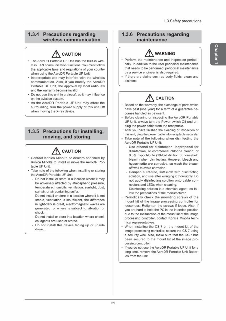
1 .3 .4 Precautions regarding wireless communication
CAUTION• The AeroDR Portable UF Unit has the built-in wire-
less LAN communication functions . You must follow the applicable laws and regulations of your country when using the AeroDR Portable UF Unit .
• Inappropriate use may interfere with the wireless communication . Also, if you modify the AeroDR Portable UF Unit, the approval by local radio law and the warranty become invalid .
• Do not use this unit in a aircraft as it may influence on the aviation system .
• As the AeroDR Portable UF Unit may affect the surrounding, turn the power supply of this unit Off when moving the X-ray device .
1 .3 .5 Precautions for installing, moving, and storing
CAUTION• Contact Konica Minolta or dealers specified by
Konica Minolta to install or move the AeroDR Por-table UF Unit .
• Take note of the following when installing or storing the AeroDR Portable UF Unit:
- Do not install or store in a location where it may be adversely affected by atmospheric pressure, temperature, humidity, ventilation, sunlight, dust, salt-air, or air containing sulfur .
- Do not install or store in a location where it is not stable, ventilation is insufficient, the difference in light-dark is great, electromagnetic waves are generated, or where is subject to vibration or shock .
- Do not install or store in a location where chemi-cal agents are used or stored .
- Do not install this device facing up or upside down .
1 .3 .6 Precautions regarding maintenance
WARNING• Perform the maintenance and inspection periodi-
cally . In addition to the user periodical maintenance that needs to be performed, periodical maintenance by a service engineer is also required .
• If there are stains such as body fluids, clean and disinfect .
CAUTION• Based on the warranty, the exchange of parts which
have past (one year) for a term of a guarantee be-comes handled as payment .
• Before cleaning or inspecting the AeroDR Portable UF Unit, always turn the Power switch Off and un-plug the power cable from the receptacle .
• After you have finished the cleaning or inspection of this unit, plug the power cable into receptacle securely .
• Take note of the following when disinfecting the AeroDR Portable UF Unit:
- Use ethanol for disinfection, isopropanol for disinfection, or commercial chlorine bleach, or 0 .5% hypochlorite (10-fold dilution of household bleach) when disinfecting . However, bleach and hypochlorite are corrosive, so wash the bleach off well to avoid corrosion .
- Dampen a lint-free, soft cloth with disinfecting solution, and use after wringing it thoroughly . Do not apply disinfecting solution onto cable con-nectors and LEDs when cleaning .
- Disinfecting solution is a chemical agent, so fol-low the precautions of the manufacturer .
• Periodically check the mounting screws of the mount kit of the image processing controller for looseness . Retighten the screws if loose . Also, if you are hard to hold the PC in the intended position due to the malfunction of the mount kit of the image processing controller, contact Konica Minolta tech-nical representatives .
• When installing the CS-7 on the mount kit of the image processing controller, secure the CS-7 using a security wire . Also, make sure that the CS-7 has been secured to the mount kit of the image pro-cessing controller .
• If you do not use the AeroDR Portable UF Unit for a long time, remove the AeroDR Portable Unit Batter-ies from the unit .
1 .3 Safety precautions
22
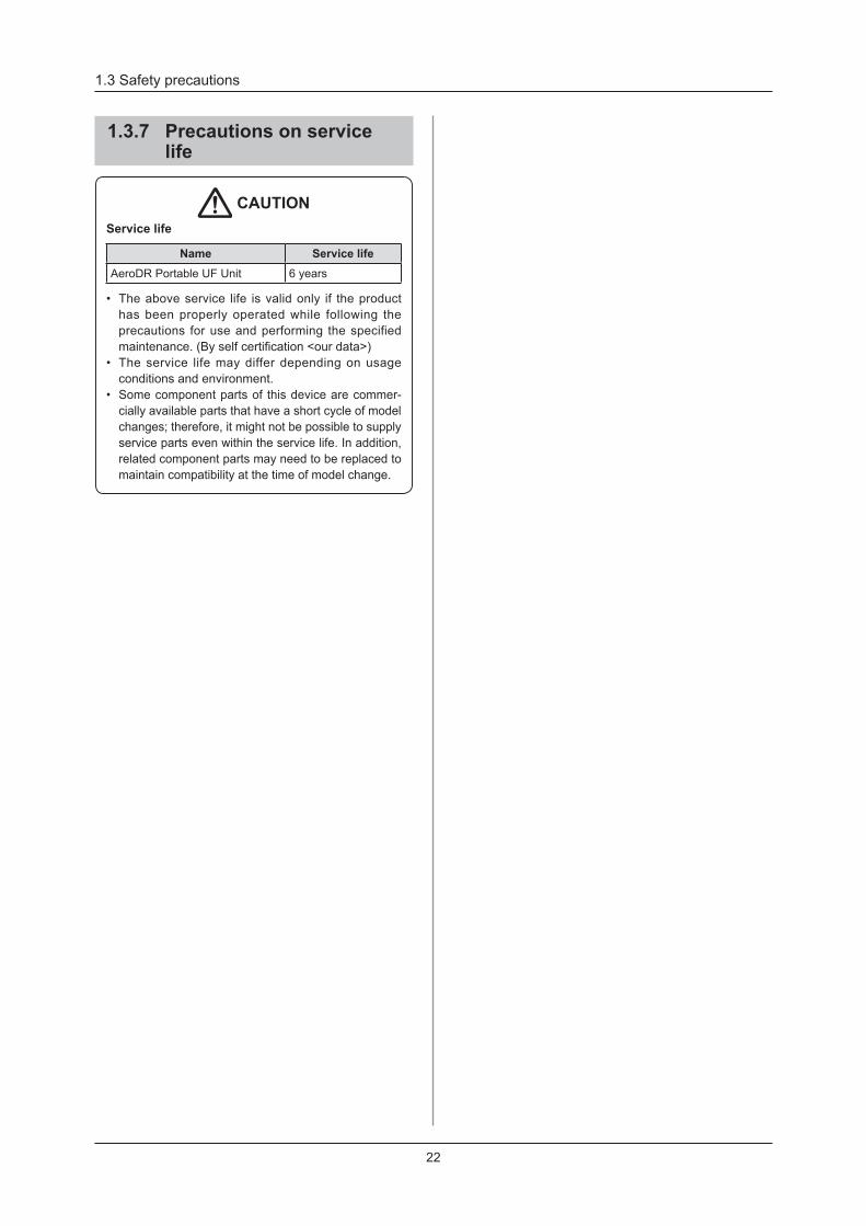
1 .3 .7 Precautions on service life
CAUTIONService life
Name Service lifeAeroDR Portable UF Unit 6 years
• The above service life is valid only if the product has been properly operated while following the precautions for use and performing the specified maintenance. (By self certification <our data>)
• The service life may differ depending on usage conditions and environment .
• Some component parts of this device are commer-cially available parts that have a short cycle of model changes; therefore, it might not be possible to supply service parts even within the service life . In addition, related component parts may need to be replaced to maintain compatibility at the time of model change .

23
Chapter 2Product Overview
This chapter describes the overview of the AeroDR Portable UF Unit .
24
2 .1 Overview of the AeroDR Portable UF Unit
This section describes the functions of AeroDR Portable UF Unit and its system configuration.
2 .1 .1 Functions
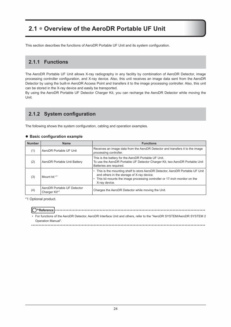
The AeroDR Portable UF Unit allows X-ray radiography in any facility by combination of AeroDR Detector, image processing controller configuration, and X-ray device. Also, this unit receives an image data sent from the AeroDR Detector by using the built-in AeroDR Access Point and transfers it to the image processing controller . Also, this unit can be stored in the X-ray device and easily be transported .By using the AeroDR Portable UF Detector Charger Kit, you can recharge the AeroDR Detector while moving the Unit .
2 .1 .2 Systemconfiguration
The following shows the system configuration, cabling and operation examples.
z BasicconfigurationexampleNumber Name Functions
(1) AeroDR Portable UF Unit Receives an image data from the AeroDR Detector and transfers it to the image processing controller .
(2) AeroDR Portable Unit BatteryThis is the battery for the AeroDR Portable UF Unit .To use the AeroDR Portable UF Detector Charger Kit, two AeroDR Portable Unit Batteries are required .
(3) Mount kit *1
• This is the mounting shelf to store AeroDR Detector, AeroDR Portable UF Unit and others in the storage of X-ray device .
• This kit mounts the image processing controller or 17-inch monitor on the X-ray device .
(4)AeroDR Portable UF Detector Charger Kit*1 Charges the AeroDR Detector while moving the Unit .
*1 Optional product .
Reference • ••••••••••••••••••••••••••••••••••••••••••••••••••••••••••••••••••••••••••••••••••••••••••••••••••••
• For functions of the AeroDR Detector, AeroDR Interface Unit and others, refer to the "AeroDR SYSTEM/AeroDR SYSTEM 2 Operation Manual" .
• ••••••••••••••••••••••••••••••••••••••••••••••••••••••••••••••••••••••••••••••••••••••••••••••••••••••••••••••••••••

25
Chapter 2
2 .1 Overview of the AeroDR Portable UF Unit
z System cabling example of AeroDR Portable UF Unit
AeroDR Detector
AeroDR Battery Charger
or
AeroDR Detector
AeroDR I/F Cable
AeroDR Interface Unit
AeroDR Detector registration side
Hub(2) AeroDR Portable
Unit Battery
(1) AeroDR Portable UF Unit
(4) AeroDR Portable UF Detector Charger Kit
Image processing controller
z Operation example of AeroDR Portable UF Unit
AeroDR DetectorImage processing
controller
(1) AeroDR Portable UF Unit
(3) Mount kit
(3) Mount kit
X-ray device
HINT • ••••••••••••••••••••••••••••••••••••••••••••••••••••••••••••••••••••••••••••••••••••••••••••••••••••
• The wired connection may be used in the AeroDR Portable UF Unit and image processing controller by preparing X-ray de-vice side hub .
• When the mount kit of the image processing controller is used, attach the image processing controller to the mount kit of the image processing controller .
• If the AeroDR Portable UF Detector Charger Kit is not used, do not use the AeroDR Portable Unit Battery on the LAN port . • ••••••••••••••••••••••••••••••••••••••••••••••••••••••••••••••••••••••••••••••••••••••••••••••••••••••••••••••••••••

26
2 .2 Component names and functions
2 .2 .1 AeroDR Portable UF Unit
The component names and functions of the AeroDR Portable UF Unit are as follows .
(11) Power cable socket
(14) Power cable
(13) Recharger unit
(9) System rear view(8) System front view
(7) Power LED light
(1) Battery insertion port
(10) Power cable cover
(2) Battery stopper(4) LAN cable
cover
(6) Power switch
(3) Holder grip (5) LAN port
(12) Power cable con-nector
Number Name Functions(1) Battery insertion port AeroDR Portable Unit Battery loading port .
(2) Battery stopper Locks and prevents the AeroDR Portable Unit Battery from falling .
(3) Holder grip This grip is used to carry the AeroDR Portable UF Unit .
(4) LAN cable cover This is the Ethernet cable connector cover .
(5) LAN port The port for connecting the image processing controller through a wired con-nection .
(6) Power switch Turns the power supply of AeroDR Portable UF Unit on and off .
(7) Power LED light
Displays the Power On/Off status and the battery alarm of AeroDR Portable Unit Batteries .
Reference • For the display patterns and status of the LEDs, refer to "Chapter 4 Status
(LED) Display" .
(8) System front view Protects the internal parts .
(9) System rear view Protects the internal parts .
(10) Power cable cover This is the cover of the power cable connector .
(11) Power cable socket This is the socket of the power cable connector .
(12) Power cable connector Plugs into the power cable socket of AeroDR Portable UF Unit .
(13) Recharger unitUsed to recharge the AeroDR Portable Unit Batteries .
(14) Power cable
27
Chapter 2
2 .2 Component names and functions
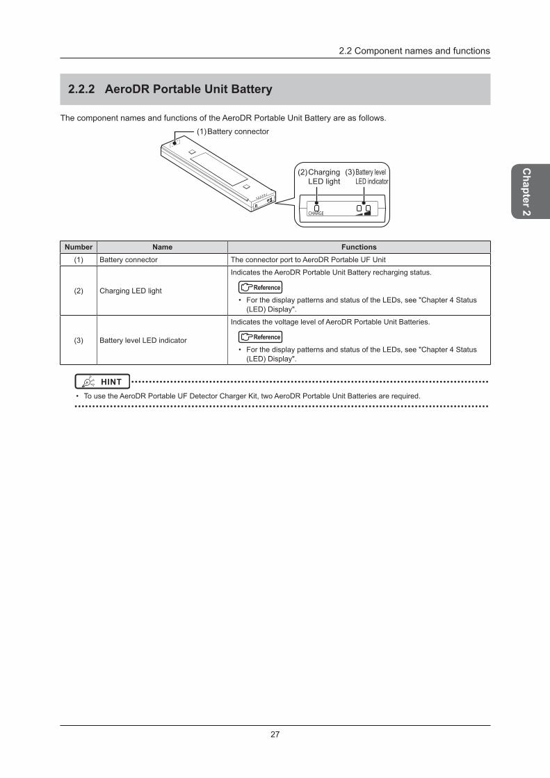
2 .2 .2 AeroDR Portable Unit Battery
The component names and functions of the AeroDR Portable Unit Battery are as follows .
(2) Charging LED light
(3) Battery level LED indicator
(1) Battery connector
Number Name Functions(1) Battery connector The connector port to AeroDR Portable UF Unit
(2) Charging LED light
Indicates the AeroDR Portable Unit Battery recharging status .
Reference • For the display patterns and status of the LEDs, see "Chapter 4 Status
(LED) Display" .
(3) Battery level LED indicator
Indicates the voltage level of AeroDR Portable Unit Batteries .
Reference • For the display patterns and status of the LEDs, see "Chapter 4 Status
(LED) Display" .
HINT • ••••••••••••••••••••••••••••••••••••••••••••••••••••••••••••••••••••••••••••••••••••••••••••••••••••
• To use the AeroDR Portable UF Detector Charger Kit, two AeroDR Portable Unit Batteries are required . • ••••••••••••••••••••••••••••••••••••••••••••••••••••••••••••••••••••••••••••••••••••••••••••••••••••••••••••••••••••

28
2 .2 Component names and functions
2 .2 .3 AeroDR Portable UF Detector Charger Kit
(1) Battery stopper (2) Battery insertion port(4) Panel Charge Cable
(6) Power cable cover
(5) Power cable socket
(3) Panel Charge port
(9) Power cable
(8) Recharger unit
(7) Power cable connector
Number Name Functions(1) Battery stopper Locks and prevents the AeroDR Portable Unit Battery from falling .
(2) Battery insertion port AeroDR Portable Unit Battery loading port .
(3) Panel Charge port The connector port to the Panel Charge Cable .
(4) Panel Charge Cable Use to recharge the AeroDR Detector .
(5) Power cable socket This is the socket of the power cable connector .
(6) Power cable cover This is the cover of the power cable connector .
(7) Power cable connector Plugs into the power cable socket of AeroDR Portable UF Unit .
(8) Recharger unitUsed to recharge the AeroDR Portable Unit Batteries .
(9) Power cable
29
Chapter 3General Operations
This chapter describes general operation methods
of the AeroDR Portable UF Unit .
30
3 .1 Startup and shutdown
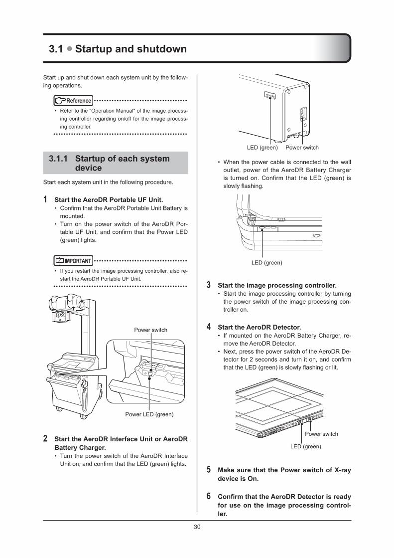
Power switchLED (green)
• When the power cable is connected to the wall outlet, power of the AeroDR Battery Charger is turned on . Confirm that the LED (green) is slowly flashing.
LED (green)
3 Start the image processing controller .• Start the image processing controller by turning
the power switch of the image processing con-troller on .
4 Start the AeroDR Detector .• If mounted on the AeroDR Battery Charger, re-
move the AeroDR Detector .• Next, press the power switch of the AeroDR De-
tector for 2 seconds and turn it on, and confirm that the LED (green) is slowly flashing or lit.
LED (green)
Power switch
5 Make sure that the Power switch of X-ray device is On .
6 ConfirmthattheAeroDRDetectorisreadyfor use on the image processing control-ler .
Start up and shut down each system unit by the follow-ing operations .
Reference • ••••••••••••••••••••••••••••••••••••
• Refer to the "Operation Manual" of the image process-ing controller regarding on/off for the image process-ing controller .
• ••••••••••••••••••••••••••••••••••••••••••••••••••••
3 .1 .1 Startup of each system device
Start each system unit in the following procedure .
1 Start the AeroDR Portable UF Unit .• Confirm that the AeroDR Portable Unit Battery is
mounted .• Turn on the power switch of the AeroDR Por-
table UF Unit, and confirm that the Power LED (green) lights .
IMPORTANT • ••••••••••••••••••••••••••••••••••••
• If you restart the image processing controller, also re-start the AeroDR Portable UF Unit .
• ••••••••••••••••••••••••••••••••••••••••••••••••••••
Power switch
Power LED (green)
2 Start the AeroDR Interface Unit or AeroDR Battery Charger .• Turn the power switch of the AeroDR Interface
Unit on, and confirm that the LED (green) lights.
3 .1 Startup and shutdown
31
Chapter 3
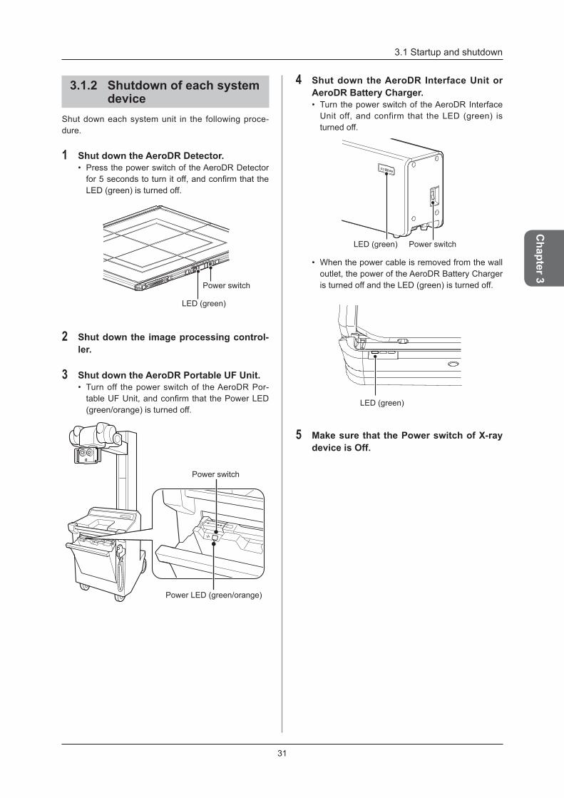
3 .1 .2 Shutdown of each system device
Shut down each system unit in the following proce-dure .
1 Shut down the AeroDR Detector .• Press the power switch of the AeroDR Detector
for 5 seconds to turn it off, and confirm that the LED (green) is turned off .
LED (green)
Power switch
2 Shut down the image processing control-ler .
3 Shut down the AeroDR Portable UF Unit .• Turn off the power switch of the AeroDR Por-
table UF Unit, and confirm that the Power LED (green/orange) is turned off .
Power switch
Power LED (green/orange)
4 Shut down the AeroDR Interface Unit or AeroDR Battery Charger .• Turn the power switch of the AeroDR Interface
Unit off, and confirm that the LED (green) is turned off .
Power switchLED (green)
• When the power cable is removed from the wall outlet, the power of the AeroDR Battery Charger is turned off and the LED (green) is turned off .
LED (green)
5 Make sure that the Power switch of X-ray device is Off .
32
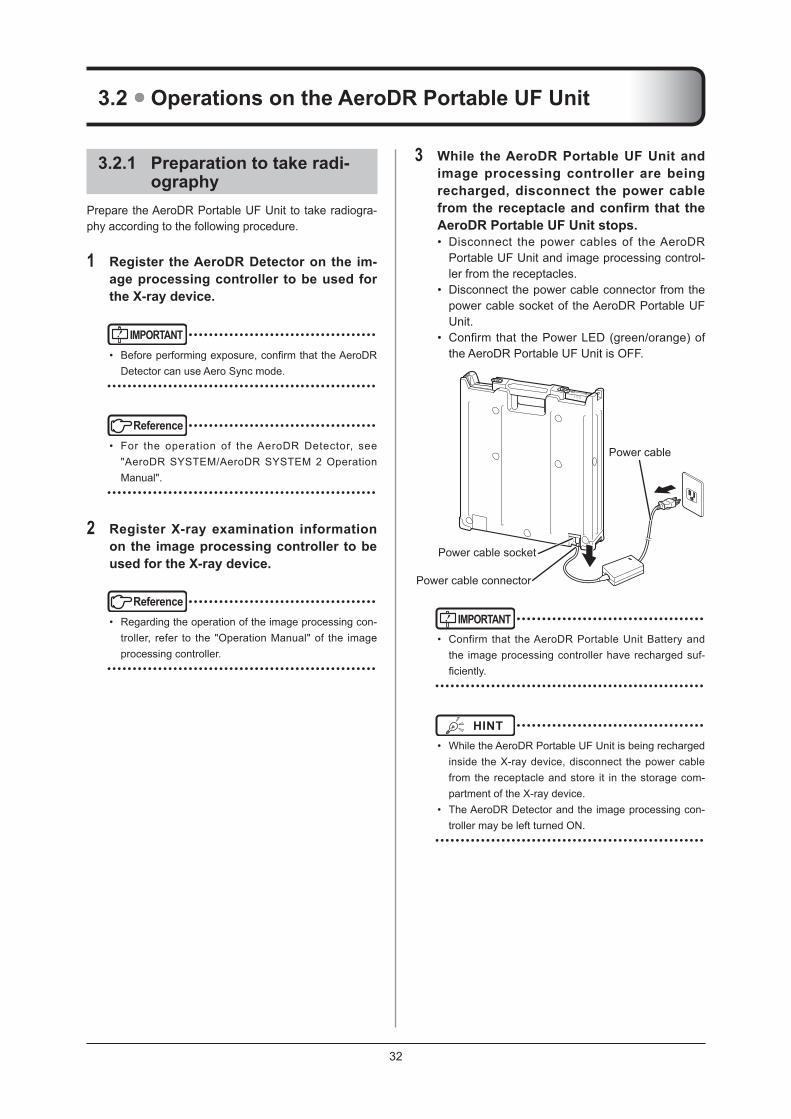
3 While the AeroDR Portable UF Unit and image processing controller are being recharged, disconnect the power cable from the receptacle and confirm that the AeroDR Portable UF Unit stops .• Disconnect the power cables of the AeroDR
Portable UF Unit and image processing control-ler from the receptacles .
• Disconnect the power cable connector from the power cable socket of the AeroDR Portable UF Unit .
• Confirm that the Power LED (green/orange) of the AeroDR Portable UF Unit is OFF .
Power cable socket
Power cable connector
Power cable
IMPORTANT • ••••••••••••••••••••••••••••••••••••
• Confirm that the AeroDR Portable Unit Battery and the image processing controller have recharged suf-ficiently.
•••••••••••••••••••••••••••••••••••••••••••••••••••••
HINT • ••••••••••••••••••••••••••••••••••••
• While the AeroDR Portable UF Unit is being recharged inside the X-ray device, disconnect the power cable from the receptacle and store it in the storage com-partment of the X-ray device .
• The AeroDR Detector and the image processing con-troller may be left turned ON .
• ••••••••••••••••••••••••••••••••••••••••••••••••••••
3 .2 .1 Preparation to take radi-ography
Prepare the AeroDR Portable UF Unit to take radiogra-phy according to the following procedure .
1 Register the AeroDR Detector on the im-age processing controller to be used for the X-ray device .
IMPORTANT • ••••••••••••••••••••••••••••••••••••
• Before performing exposure, confirm that the AeroDR Detector can use Aero Sync mode .
• ••••••••••••••••••••••••••••••••••••••••••••••••••••
Reference • ••••••••••••••••••••••••••••••••••••
• For the operation of the AeroDR Detector, see "AeroDR SYSTEM/AeroDR SYSTEM 2 Operation Manual" .
• ••••••••••••••••••••••••••••••••••••••••••••••••••••
2 Register X-ray examination information on the image processing controller to be used for the X-ray device .
Reference • ••••••••••••••••••••••••••••••••••••
• Regarding the operation of the image processing con-troller, refer to the "Operation Manual" of the image processing controller .
• ••••••••••••••••••••••••••••••••••••••••••••••••••••
3 .2 Operations on the AeroDR Portable UF Unit

3 .2 Operations on the AeroDR Portable UF Unit
33
Chapter 3
4 Remove the Ethernet cable that is con-nected to the AeroDR Detector registra-tion side hub from the image processing controller .
Image processing controller
Ethernet cable
HINT • ••••••••••••••••••••••••••••••••••••
• When the AeroDR Portable UF Unit and image pro-cessing controller use a wired connection, disconnect the Ethernet cable that is connected to the AeroDR Detector registration side hub from the X-ray device side hub .
• ••••••••••••••••••••••••••••••••••••••••••••••••••••
5 Set the AeroDR Detector, AeroDR Portable UF Unit and image processing controller on the X-ray device, and move them to the exposure area .
AeroDR Portable UF Unit
AeroDR Detector
Image process-ing controller
HINT • ••••••••••••••••••••••••••••••••••••
• When the mount kit of the image processing controller is used, attach the image processing controller to the mount kit of the image processing controller .
• ••••••••••••••••••••••••••••••••••••••••••••••••••••
3 .2 .2 Exposure
Carry out radiography using the AeroDR Portable UF Unit according to the following procedure .
IMPORTANT • ••••••••••••••••••••••••••••••••••••
• Do not recharge the AeroDR Portable Unit Battery during exposure .
• ••••••••••••••••••••••••••••••••••••••••••••••••••••
1 When the car arrives at the destination, take the AeroDR Detector and image pro-cessing controller out .
2 Turn the power switch of each equipment ON .
IMPORTANT • ••••••••••••••••••••••••••••••••••••
• After the AeroDR Portable UF Unit is turned ON, it may require approximately 1 minute for wireless con-nection .
• ••••••••••••••••••••••••••••••••••••••••••••••••••••
Reference • ••••••••••••••••••••••••••••••••••••
• For the startup of each system, refer to "3 .1 Startup and shutdown" .
• ••••••••••••••••••••••••••••••••••••••••••••••••••••
3 Check that each unit is ready to operate, and prepare to take radiography .
4 Press the exposure switch of the X-ray device and perform exposure .• When the exposure is completed, images are
stored in the AeroDR Detector, and sequentially converted to digital data and sent to the image processing controller .
3 .2 Operations on the AeroDR Portable UF Unit
34
5 Check that the exposed image is dis-played on the image processing control-ler .
IMPORTANT • ••••••••••••••••••••••••••••••••••••
• The AeroDR detector is precision equipment, and therefore impact or vibration during radiography or im-age transfer may affect the image quality . Be careful when handling the AeroDR detector during and just after radiography .
• ••••••••••••••••••••••••••••••••••••••••••••••••••••
HINT • ••••••••••••••••••••••••••••••••••••
• If the AeroDR Detector remains unused for a long time (time can be set), it transitions to the sleep mode .
• When the image processing controller is ready to ex-pose, it recovers from the sleep mode .
• ••••••••••••••••••••••••••••••••••••••••••••••••••••
Reference • ••••••••••••••••••••••••••••••••••••
• Regarding the operation of image processing control-ler, refer to the "Operation Manual" of the image pro-cessing controller .
• ••••••••••••••••••••••••••••••••••••••••••••••••••••
6 When moving the AeroDR Portable UF Unit, turn the unit OFF because its wire-less communication may affect the sur-rounding .• Use the power switch to turn OFF the AeroDR
Portable UF Unit and confirm that the Power LED (green/orange) is turned OFF .
3 .2 .3 Operations after radiogra-phy
After you finish taking radiography, follow the proce-dures below .
1 Afteryoufinishtakingradiography,storethe AeroDR Detector and image process-ing controller in the X-ray device .
2 Shut down the AeroDR Portable UF Unit .• Turn the AeroDR Portable UF Unit OFF and
confirm that the Power LED (green/orange) is turned OFF .
HINT • ••••••••••••••••••••••••••••••••••••
• The AeroDR Detector and the image processing controller may be left turned ON .
• ••••••••••••••••••••••••••••••••••••••••••••••••••••
Reference • ••••••••••••••••••••••••••••••••••••
• For the shutdown of the AeroDR Portable UF Unit, re-fer to "3 .1 Startup and shutdown" .
• ••••••••••••••••••••••••••••••••••••••••••••••••••••
3 Move the X-ray device .
4 Connect the Ethernet cable that is con-nected to the AeroDR Detector registra-tion side hub to the image processing controller .
HINT • ••••••••••••••••••••••••••••••••••••
• When a wired connection is used between the AeroDR Portable UF Unit and image processing controller, connect the Ethernet cable that is connected to the AeroDR Detector registration side hub to the X-ray de-vice side hub .
• ••••••••••••••••••••••••••••••••••••••••••••••••••••
5 Output taken images from the image pro-cessing controller used for the X-ray de-vice .
Reference • ••••••••••••••••••••••••••••••••••••
• Regarding the operation of image processing control-ler, refer to the "Operation Manual" of the image pro-cessing controller .
• ••••••••••••••••••••••••••••••••••••••••••••••••••••
3 .2 Operations on the AeroDR Portable UF Unit
35
Chapter 3
6 Plug the power cables in a receptacle to recharge the AeroDR Portable UF Unit and the image processing controller .
7 Recharge the AeroDR Detector and the X-ray device .
Reference • ••••••••••••••••••••••••••••••••••••
• For the operation of the AeroDR Detector, see "AeroDR SYSTEM/AeroDR SYSTEM 2 Operation Manual" .
• ••••••••••••••••••••••••••••••••••••••••••••••••••••
3 .2 .4 Mounting or dismounting the AeroDR Portable Unit Battery
z Mounting
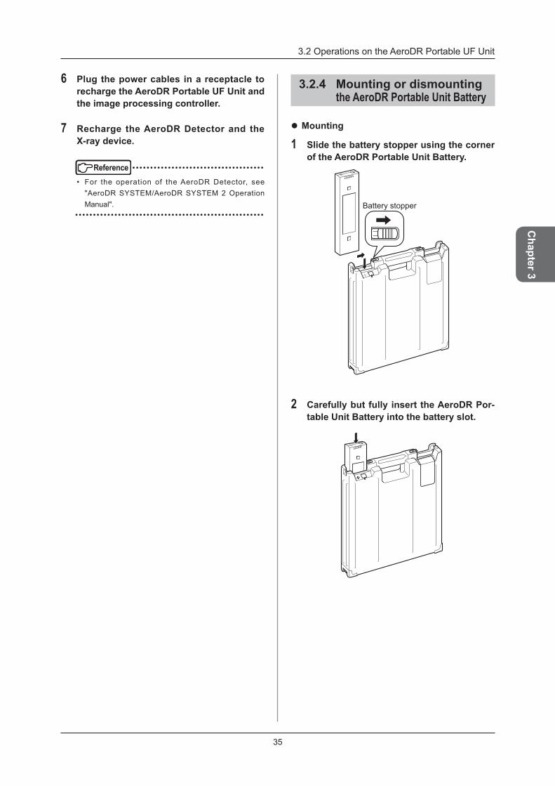
1 Slide the battery stopper using the corner of the AeroDR Portable Unit Battery .
Battery stopper
2 Carefully but fully insert the AeroDR Por-table Unit Battery into the battery slot .

3 .2 Operations on the AeroDR Portable UF Unit
36
3 Make sure that the AeroDR Portable Unit Battery is locked and secured by the bat-tery stopper .
Battery stopper
z Dismounting
1 Slide the battery stopper to release it .Battery stopper
2 Pull out the AeroDR Portable Unit Battery from the battery slot .
HINT • ••••••••••••••••••••••••••••••••••••
• The AeroDR Portable Unit Battery on the AeroDR Portable UF Detector Charger Kit side is inserted or removed in the same way .
• ••••••••••••••••••••••••••••••••••••••••••••••••••••
3 .2 Operations on the AeroDR Portable UF Unit
37
Chapter 3
3 .2 .5 Operating the mount kit
IMPORTANT • ••••••••••••••••••••••••••••••••••••
• Do not forcefully spin the mount kit of the image pro-cessing controller .
• Be careful not to pinch your fingers during operation. •••••••••••••••••••••••••••••••••••••••••••••••••••••
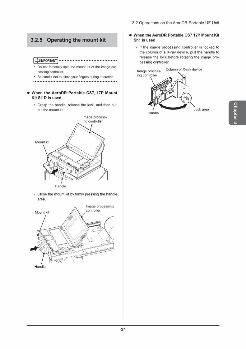
z When the AeroDR Portable CS7_17P Mount Kit Si1D is used
• Grasp the handle, release the lock, and then pull out the mount kit .
Handle
Image process-ing controller
Mount kit
• Close the mount kit by firmly pressing the handle area .
Handle
Mount kit
Image processing controller
z When the AeroDR Portable CS7 12P Mount Kit Sh1 is used
• If the image processing controller is locked to the column of a X-ray device, pull the handle to release the lock before rotating the image pro-cessing controller .
Column of X-ray device
Lock areaHandle
Image process-ing controller
3 .2 Operations on the AeroDR Portable UF Unit
38
3 .2 .6 Precautions of operations
IMPORTANT • ••••••••••••••••••••••••••••••••••••
• Do not rotate the mount kit of the image processing controller swiftly .
• ••••••••••••••••••••••••••••••••••••••••••••••••••••
When transporting the X-ray device
IMPORTANT • ••••••••••••••••••••••••••••••••••••
• Turn off the AeroDR Portable UF Unit when transport-ing the X-ray device because it may affect the sur-roundings with radio transmissions .
• ••••••••••••••••••••••••••••••••••••••••••••••••••••
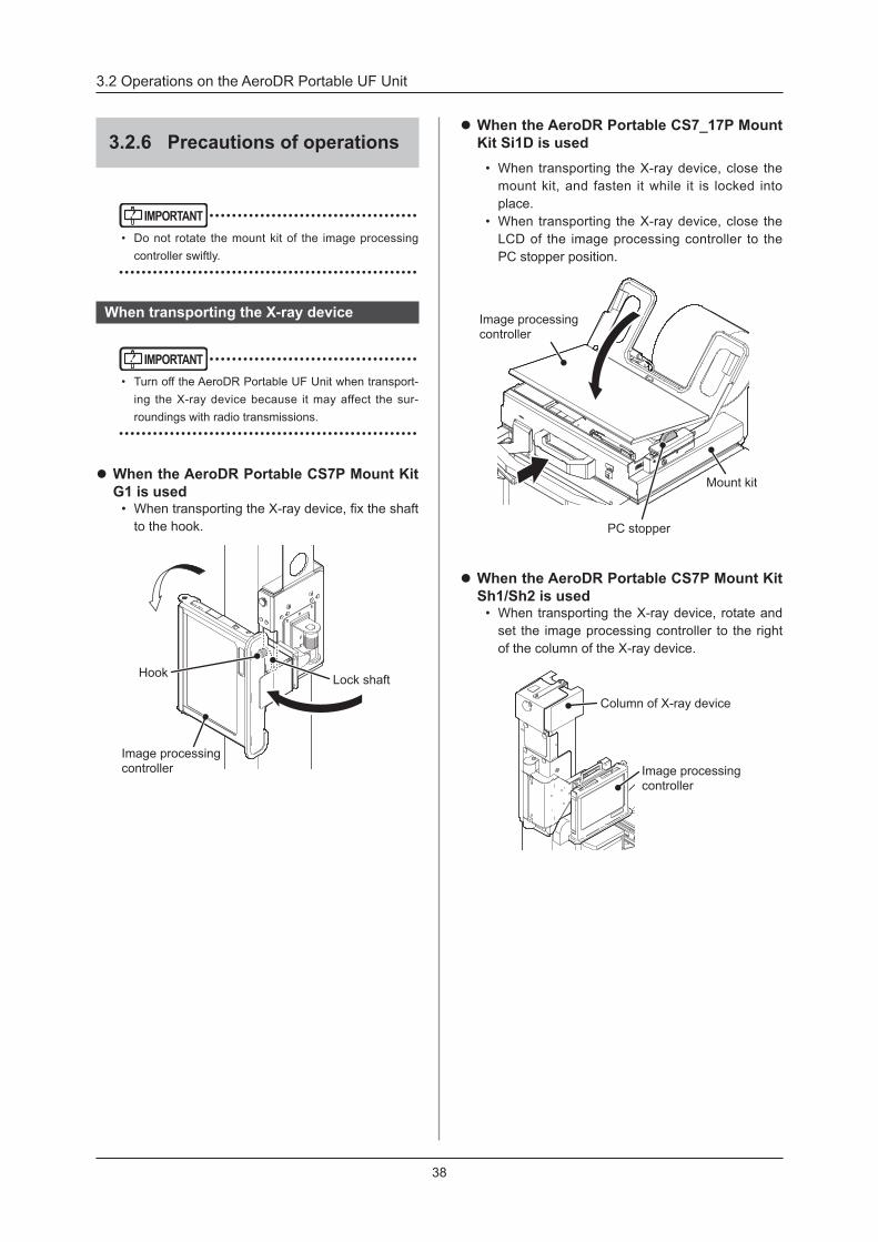
z When the AeroDR Portable CS7P Mount Kit G1 is used
• When transporting the X-ray device, fix the shaft to the hook .
Lock shaft
Image processing controller
Hook
z When the AeroDR Portable CS7_17P Mount Kit Si1D is used
• When transporting the X-ray device, close the mount kit, and fasten it while it is locked into place .
• When transporting the X-ray device, close the LCD of the image processing controller to the PC stopper position .
PC stopper
Mount kit
Image processing controller
z When the AeroDR Portable CS7P Mount Kit Sh1/Sh2 is used
• When transporting the X-ray device, rotate and set the image processing controller to the right of the column of the X-ray device .
Column of X-ray device
Image processing controller
3 .2 Operations on the AeroDR Portable UF Unit
39
Chapter 3
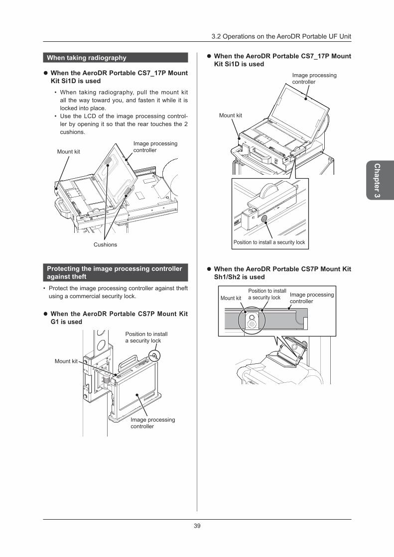
When taking radiography
z When the AeroDR Portable CS7_17P Mount Kit Si1D is used
• When taking radiography, pull the mount kit all the way toward you, and fasten it while it is locked into place .
• Use the LCD of the image processing control-ler by opening it so that the rear touches the 2 cushions .
Mount kit
Cushions
Image processing controller
Protecting the image processing controller against theft
• Protect the image processing controller against theft using a commercial security lock .
z When the AeroDR Portable CS7P Mount Kit G1 is used
Mount kit
Image processing controller
Position to install a security lock
z When the AeroDR Portable CS7_17P Mount Kit Si1D is used
Image processing controller
Position to install a security lock
Mount kit
z When the AeroDR Portable CS7P Mount Kit Sh1/Sh2 is used
Mount kit Image processing controller
Position to install a security lock
3 .2 Operations on the AeroDR Portable UF Unit
40
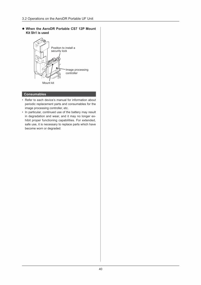
z When the AeroDR Portable CS7 12P Mount Kit Sh1 is used
Mount kit
Image processing controller
Position to install a security lock
Consumables• Refer to each device’s manual for information about
periodic replacement parts and consumables for the image processing controller, etc .
• In particular, continued use of the battery may result in degradation and wear, and it may no longer ex-hibit proper functioning capabilities . For extended, safe use, it is necessary to replace parts which have become worn or degraded .
41
Chapter 3
IMPORTANT • ••••••••••••••••••••••••••••••••••••
• Never carry out exposure while recharging the Aero-DR Portable Unit Battery .
• When charging is completed or the power cable is disconnected, the CHARGE LED (blue) lamp may become unstable . But, there is nothing wrong with the equipment .
• ••••••••••••••••••••••••••••••••••••••••••••••••••••
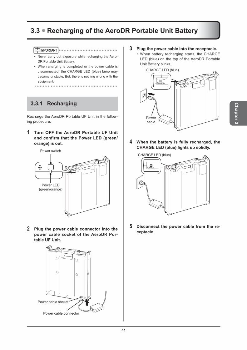
3 .3 .1 Recharging
Recharge the AeroDR Portable UF Unit in the follow-ing procedure .
1 Turn OFF the AeroDR Portable UF Unit and confirm that the Power LED (green/orange) is out .
Power LED (green/orange)
Power switch
2 Plug the power cable connector into the power cable socket of the AeroDR Por-table UF Unit .
Power cable socket
Power cable connector
3 Plug the power cable into the receptacle .• When battery recharging starts, the CHARGE
LED (blue) on the top of the AeroDR Portable Unit Battery blinks .
CHARGE LED (blue)
Power cable
4 When the battery is fully recharged, the CHARGELED(blue)lightsupsolidly.CHARGE LED (blue)
5 Disconnect the power cable from the re-ceptacle .
3 .3 Recharging of the AeroDR Portable Unit Battery

3 .3 Recharging of the AeroDR Portable Unit Battery
42
3 .3 .2 When recharging the battery with the AeroDR Portable UF Unit inserted in the X-ray device
To recharge the battery with the AeroDR Portable UF Unit inserted in the X-ray device, follow the steps be-low .
1 Turn OFF the AeroDR Portable UF Unit and confirm that the Power LED (green/orange) is turned OFF .
Power switch
Power LED (green/orange)
2 Take out the power cable stored in the X-ray device .
Power cable
3 Plug the power cable into a receptacle .• When battery recharging starts, the CHARGE
LED (blue) on the top of the AeroDR Portable Unit Battery blinks .
Power cable
CHARGE LED (blue)
4 When the battery is fully recharged, the CHARGELED(blue)lightsupsolidly.
CHARGE LED (blue)
5 Disconnect the power cable from the re-ceptacle and store it in the X-ray device .
3 .3 Recharging of the AeroDR Portable Unit Battery
43
Chapter 3
3 .3 .3 Charging time guide
It takes approximately 5 hours to fully charge up AeroDR Portable Unit Batteries if they have been fully discharged .
HINT • ••••••••••••••••••••••••••••••••••••
• The charging time of AeroDR Portable Unit Batteries vary depending on the battery application environment and frequency of usage .
• ••••••••••••••••••••••••••••••••••••••••••••••••••••
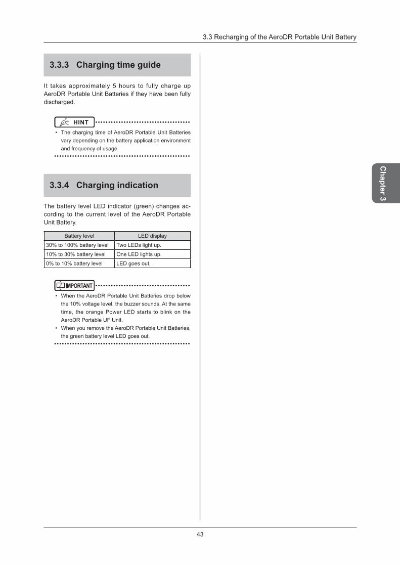
3 .3 .4 Charging indication
The battery level LED indicator (green) changes ac-cording to the current level of the AeroDR Portable Unit Battery .
Battery level LED display
30% to 100% battery level Two LEDs light up .
10% to 30% battery level One LED lights up .
0% to 10% battery level LED goes out .
IMPORTANT • ••••••••••••••••••••••••••••••••••••
• When the AeroDR Portable Unit Batteries drop below the 10% voltage level, the buzzer sounds . At the same time, the orange Power LED starts to blink on the AeroDR Portable UF Unit .
• When you remove the AeroDR Portable Unit Batteries, the green battery level LED goes out .
• ••••••••••••••••••••••••••••••••••••••••••••••••••••

44
3 .4 Operations on the AeroDR Portable UF Detector Charger Kit
By using the AeroDR Portable UF Detector Charger Kit, you can recharge the AeroDR Detector while mov-ing the Unit .
IMPORTANT • ••••••••••••••••••••••••••••••••••••
• Do not recharge the AeroDR Detector using the AeroDR Portable UF Detector Charger Kit when an exposure is being carried out .
• The battery level LED of the AeroDR Portable Unit Battery on the AeroDR Portable UF Detector Charger Kit side remains lit even when the AeroDR Portable UF Unit power switch is turned off .
• Even when the battery level of the AeroDR Portable Unit Batteries on the AeroDR Portable UF Detector Charger Kit side drops below the 10% voltage level, the buzzer will not activate . In addition, the orange Power LED will not start to blink .
• ••••••••••••••••••••••••••••••••••••••••••••••••••••
3 .4 .1 Preparation
Prepare the AeroDR Portable UF Detector Charger Kit according to the following procedure .
1 If the AeroDR Portable Unit Battery on the AeroDR Portable UF Detector Charger Kit sideisbeingrecharged,finishrechargingit .• Disconnect the power cable of the AeroDR Por-
table Unit Battery from the receptacle .• Disconnect the power cable connector from the
power cable socket of the AeroDR Portable UF Unit .
Power cable socket
Power cable connector
Power cable
IMPORTANT • ••••••••••••••••••••••••••••••••••••
• Check that the AeroDR Portable Unit Battery on the AeroDR Portable UF Detector Charger Kit side is fully charged .
• ••••••••••••••••••••••••••••••••••••••••••••••••••••
2 If the Panel Charge Cable has been re-moved, connect it to the AeroDR Portable UF Unit .• Remove the LAN cable cover .• Connect the Panel Charge Cable to the Panel
Charge port .

3 .4 Operations on the AeroDR Portable UF Detector Charger Kit
45
Chapter 3
3 .4 .2 Recharging of the AeroDR Detector
While the Unit is being moved, the procedure to re-charge the AeroDR Detector using the AeroDR Por-table UF Detector Charger Kit is as follows .
IMPORTANT • ••••••••••••••••••••••••••••••••••••
• Do not recharge the AeroDR Detector using the AeroDR Portable UF Detector Charger Kit when an exposure is being carried out .
• Do not recharge the AeroDR Detector while recharg-ing the AeroDR Portable Unit Battery .
• ••••••••••••••••••••••••••••••••••••••••••••••••••••
HINT • ••••••••••••••••••••••••••••••••••••
• The effect of charging is the same as that achieved when using the AeroDR I/F Cable .
• ••••••••••••••••••••••••••••••••••••••••••••••••••••
1 Securely connect the Panel Charge Cable to the wired connector of the AeroDR De-tector . Once it is connected, the AeroDR Detector will be charged .
IMPORTANT • ••••••••••••••••••••••••••••••••••••
• To check the charge condition of the AeroDR Detector, use the image processing controller .
• Note that the connection direction is the reverse of the connection direction used with the AeroDR I/F Cable .
• ••••••••••••••••••••••••••••••••••••••••••••••••••••
3 .4 .3 Operations after recharg-ing the AeroDR Detector
After recharging the AeroDR Detector, follow the pro-cedures below .
IMPORTANT • ••••••••••••••••••••••••••••••••••••
• Do not recharge the AeroDR Detector while recharg-ing the AeroDR Portable Unit Battery .
• ••••••••••••••••••••••••••••••••••••••••••••••••••••
1 Recharge the AeroDR Portable Unit Bat-tery on the AeroDR Portable UF Detector Charger Kit side .• Plug the power cable connector into the power
cable socket of the AeroDR Portable UF Unit . • Plug the power cable of the AeroDR Portable
Unit Battery into the receptacle .Power cable socket
Power cable connector
Power cable
3 .4 Operations on the AeroDR Portable UF Detector Charger Kit
46
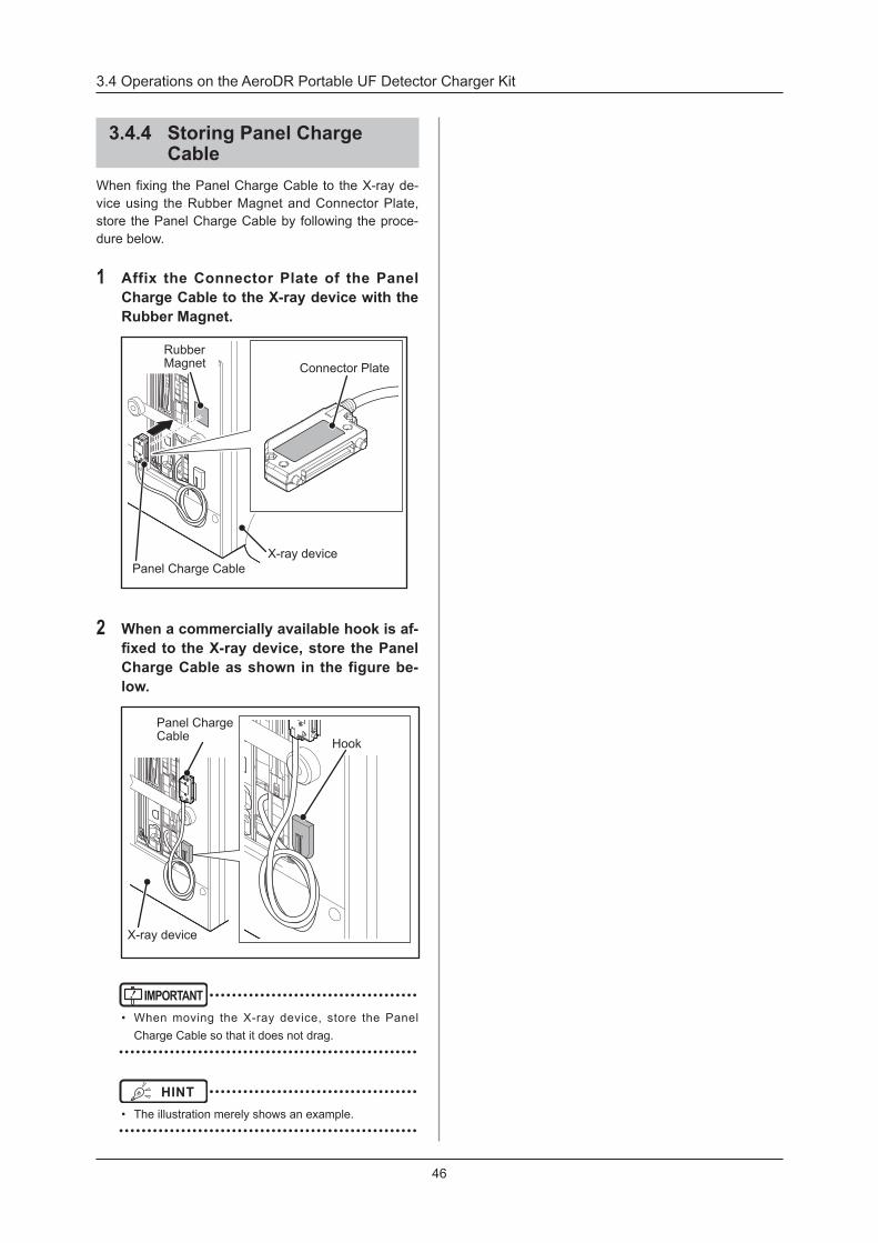
3 .4 .4 Storing Panel Charge Cable
When fixing the Panel Charge Cable to the X-ray de-vice using the Rubber Magnet and Connector Plate, store the Panel Charge Cable by following the proce-dure below .
1 Affix the Connector Plate of the Panel Charge Cable to the X-ray device with the Rubber Magnet .
Rubber Magnet Connector Plate
Panel Charge CableX-ray device
2 When a commercially available hook is af-fixedtotheX-raydevice,storethePanelCharge Cable as shown in the figure be-low .
Hook
Panel Charge Cable
X-ray device
IMPORTANT • ••••••••••••••••••••••••••••••••••••
• When moving the X-ray device, store the Panel Charge Cable so that it does not drag .
• ••••••••••••••••••••••••••••••••••••••••••••••••••••
HINT • ••••••••••••••••••••••••••••••••••••
• The illustration merely shows an example . • ••••••••••••••••••••••••••••••••••••••••••••••••••••

47
Chapter 4Status (LED) Display
This chapter describes the LED display patterns and the status
of the respective devices .

48
Status of the respective devices can be confirmed with LEDs. Check the status of the respective devices, referring to the "LED display pattern" .
LED display patternNotation Display pattern
Off
Flashing
On
4 .1 .1 AeroDR Portable UF Unit
Power LED light
Power LED (green/orange)Display pattern Status
Shutdown condition
The level of AeroDR Portable Unit Batteries is lower than 10% (and the orange LED blinks) .
The system is operating or the level of AeroDR Portable Unit Batteries is 10% to 100% (and the green LED lights) .
4 .1 .2 AeroDR Portable Unit Battery
CHARGE :CHARGELED(blue)Display pattern Status
Shutdown condition
The battery is being charged .
The battery has been charged .
:BatterylevelLED(green)Display pattern Status
The battery level is lower than 10 %, or no battery charge remaining .
When two LEDs light up, the battery is 30% to 100% charged .When one LED lights up, the battery is 10% to 30% charged .
4 .1 LED display of respective devices

49
Chapter 5Troubleshooting
This chapter describes problems that may occur and error codes that may be
displayed, and how to resolve each of them .
50
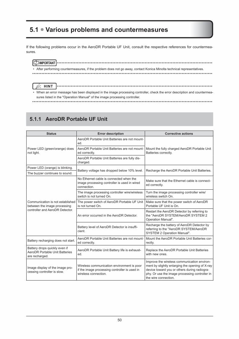
5 .1 Various problems and countermeasures
If the following problems occur in the AeroDR Portable UF Unit, consult the respective references for countermea-sures .
IMPORTANT • ••••••••••••••••••••••••••••••••••••••••••••••••••••••••••••••••••••••••••••••••••••••••••••••••••••
• After performing countermeasures, if the problem does not go away, contact Konica Minolta technical representatives . • ••••••••••••••••••••••••••••••••••••••••••••••••••••••••••••••••••••••••••••••••••••••••••••••••••••••••••••••••••••
HINT • ••••••••••••••••••••••••••••••••••••••••••••••••••••••••••••••••••••••••••••••••••••••••••••••••••••
• When an error message has been displayed in the image processing controller, check the error description and countermea-sures listed in the "Operation Manual" of the image processing controller .
• ••••••••••••••••••••••••••••••••••••••••••••••••••••••••••••••••••••••••••••••••••••••••••••••••••••••••••••••••••••
5 .1 .1 AeroDR Portable UF Unit
Status Error description Corrective actions
Power LED (green/orange) does not light .
AeroDR Portable Unit Batteries are not mount-ed .
Mount the fully charged AeroDR Portable Unit Batteries correctly .
AeroDR Portable Unit Batteries are not mount-ed correctly .
AeroDR Portable Unit Batteries are fully dis-charged .
Power LED (orange) is blinking .Battery voltage has dropped below 10% level . Recharge the AeroDR Portable Unit Batteries .
The buzzer continues to sound .
Communication is not established between the image processing controller and AeroDR Detector .
No Ethernet cable is connected when the image processing controller is used in wired connection .
Make sure that the Ethernet cable is connect-ed correctly .
The image processing controller wire/wireless switch is not turned On .
Turn the image processing controller wire/wireless switch On .
The power switch of AeroDR Portable UF Unit is not turned On .
Make sure that the power switch of AeroDR Portable UF Unit is On .
An error occurred in the AeroDR Detector .Restart the AeroDR Detector by referring to the "AeroDR SYSTEM/AeroDR SYSTEM 2 Operation Manual" .
Battery level of AeroDR Detector is insuffi-cient .
Recharge the battery of AeroDR Detector by referring to the "AeroDR SYSTEM/AeroDR SYSTEM 2 Operation Manual" .
Battery recharging does not start . AeroDR Portable Unit Batteries are not mount-ed correctly .
Mount the AeroDR Portable Unit Batteries cor-rectly .
Battery drops quickly even if AeroDR Portable Unit Batteries are recharged .
AeroDR Portable Unit Battery life is exhaust-ed .
Replace the AeroDR Portable Unit Batteries with new ones .
Image display of the image pro-cessing controller is slow .
Wireless communication environment is poor if the image processing controller is used in wireless connection .
Improve the wireless communication environ-ment by slightly enlarging the opening of X-ray device toward you or others during radiogra-phy . Or use the image processing controller in the wire connection .

5 .1 Various problems and countermeasures
51
Chapter 5
5 .1 .2 AeroDR Portable UF Detector Charger Kit
Status Error description Corrective actions
The Panel Charge Cable can-not be connected to the AeroDR Detector .
Part of the wired connection connector of the AeroDR Detector is deformed . Contact Konica Minolta technical representa-
tives .The spring connector of the Panel Charge Cable is deformed .
Foreign material is in the wired connection connector of the AeroDR Detector . Refer to "6 .1 .2 Cleaning" and remove the for-
eign material .Foreign material is in the spring connector of the Panel Charge Cable .
Charging of the AeroDR Detector does not start .
The connector of the Panel Charge Cable is not connected properly .
Correctly connect the connector of the Panel Charge Cable and the AeroDR Detector .
The Panel Charge Cable is not connected to the Panel Charge port properly .
Correctly connect the Panel Charge Cable to the Panel Charge port .
There is insufficient power remaining in the AeroDR Portable Unit Battery on the AeroDR Portable UF Detector Charger Kit side .
Recharge the AeroDR Portable Unit Battery on the AeroDR Portable UF Detector Charger Kit side .
The Panel Charge Cable may be disconnect-ed .
Contact Konica Minolta technical representa-tives .

52
53
Chapter 6Maintenance
This chapter describes the items that require periodic maintenance .

54
6 .1 Maintenance and inspection items
This chapter describes the inspections and cleaning required in order to maintain the use of the AeroDR Portable UF Unit in an optimum condition .
6 .1 .1 Maintenance schedule
The maintenance and inspection items that the user should perform are as follows .
Maintenance taskMainte-nance
intervalChecking and cleaning the surface of the AeroDR Portable UF Unit
Weekly
Checking for external damage to the AeroDR Portable UF Unit
Weekly
Full charge of the AeroDR Portable Unit Battery Monthly
Cleaning the spring connector of the Panel Charge Cable Weekly
IMPORTANT • ••••••••••••••••••••••••••••••••••••
• To ensure optimum use of the AeroDR Portable UF Unit, be sure to perform periodic maintenance .
• The above task intervals are estimates and vary ac-cording to usage .
• ••••••••••••••••••••••••••••••••••••••••••••••••••••
6 .1 .2 Cleaning
z AeroDR Portable UF UnitClean dust on the insert table of the AeroDR Portable UF Unit with a soft cloth moistened with anhydrous al-cohol or water .
Panel Charge portLAN port
Power LED light
Power cable socket
z Spring connectorIf foreign material has adhered to the spring connector of the Panel Charge Cable, remove it with a commer-cial plastic brush .
Spring connector
IMPORTANT • ••••••••••••••••••••••••••••••••••••
• Be careful not to apply any cleaning chemical or liquid onto the Power LED, LAN port, power cable socket and Panel Charge port .
• Do not clean with sharp or hard metal objects . If you cannot remove stains, contact Konica Minolta techni-cal representatives .
• ••••••••••••••••••••••••••••••••••••••••••••••••••••
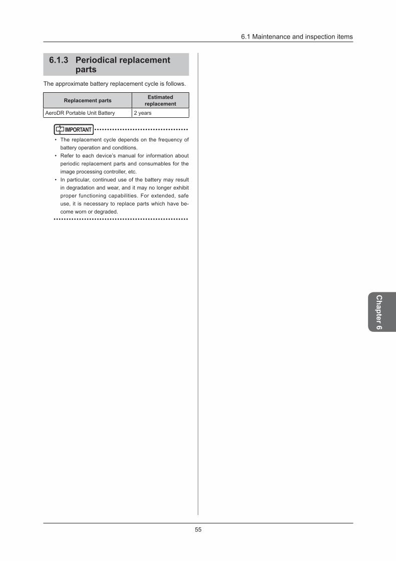
55
6 .1 Maintenance and inspection items
Chapter 6
6 .1 .3 Periodical replacement parts
The approximate battery replacement cycle is follows .
Replacement parts Estimated replacement
AeroDR Portable Unit Battery 2 years
IMPORTANT • ••••••••••••••••••••••••••••••••••••
• The replacement cycle depends on the frequency of battery operation and conditions .
• Refer to each device’s manual for information about periodic replacement parts and consumables for the image processing controller, etc .
• In particular, continued use of the battery may result in degradation and wear, and it may no longer exhibit proper functioning capabilities . For extended, safe use, it is necessary to replace parts which have be-come worn or degraded .
• ••••••••••••••••••••••••••••••••••••••••••••••••••••

56

57
Chapter 7Specifications
This chapter describes the specifications of each system device.

58
7 .1 Specifications
7 .1 .1 AeroDR Portable UF Unit
Item DescriptionProduct name AeroDR Portable UF Unit
Power requirements Normal operation: DC24 .6±0 .3V 2 .0A direct currentDuring charging: AC 100/110/115/120/200/220/230/240 VAC ±10%, single phase, 50/60 Hz
External dimensions
386(W)×72(D)×386(H)mm
386mm
386mm72mm
Weight 5 .0 kg (Including one AeroDR Portable Unit Battery)Battery operating time Approx . 11 hours
Battery Charger Specifications
Product Name: Battery Charger (Product Number: RPC Co .MDA10125202000)Dimensions: 140×62×35 mm (excluding cables)Weight: 300 gSafety Standards: UL1310, EN60355INPUT: AC100 to 240 V 1 .8 A(MAX .) 50/60 HzOUTPUT: DC24 .6V(MIN .) 2 .0A
• The described performance may change depending on the environment and frequency of use . (This is not a guarantee of performance .)
• The described battery performance is the performance after being fully charged .
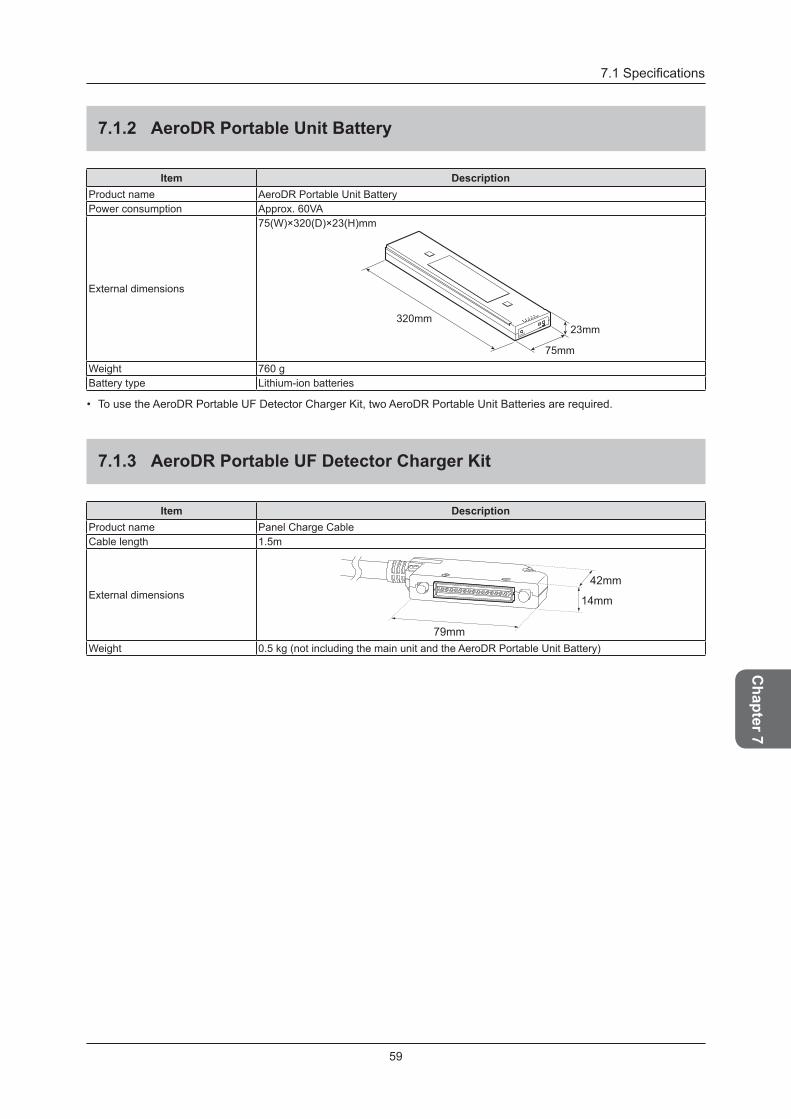
59
7.1 Specifications
Chapter 7
7 .1 .2 AeroDR Portable Unit Battery
Item DescriptionProduct name AeroDR Portable Unit BatteryPower consumption Approx . 60VA
External dimensions
75(W)×320(D)×23(H)mm
75mm
23mm320mm
Weight 760 gBattery type Lithium-ion batteries
• To use the AeroDR Portable UF Detector Charger Kit, two AeroDR Portable Unit Batteries are required .
7 .1 .3 AeroDR Portable UF Detector Charger Kit
Item DescriptionProduct name Panel Charge CableCable length 1 .5m
External dimensions42mm
14mm
79mmWeight 0 .5 kg (not including the main unit and the AeroDR Portable Unit Battery)
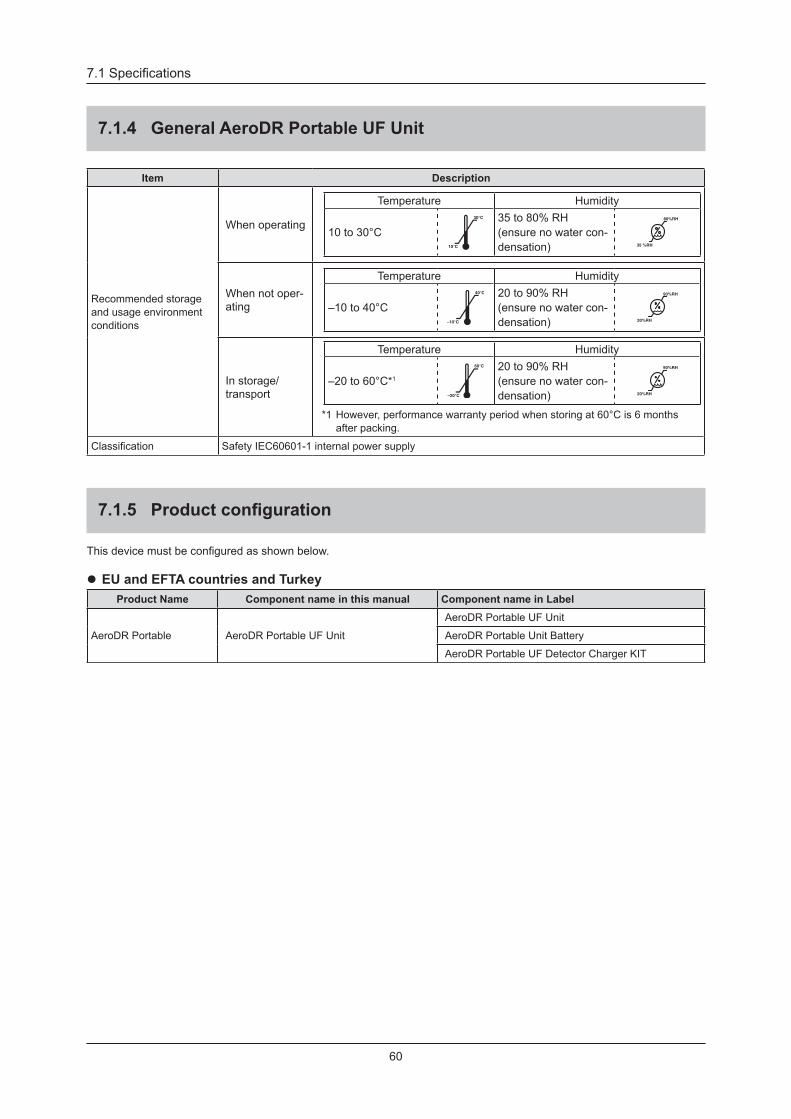
60
7.1 Specifications
7 .1 .4 General AeroDR Portable UF Unit
Item Description
Recommended storage and usage environment conditions
When operating
Temperature Humidity
10 to 30°C30°C
10°C
35 to 80% RH (ensure no water con-densation) 35 %RH
80%RH
When not oper-ating
Temperature Humidity
–10 to 40°C40°C
–10°C
20 to 90% RH (ensure no water con-densation) 20%RH
90%RH
In storage/transport
Temperature Humidity
–20 to 60°C*1
60°C
–20°C
20 to 90% RH (ensure no water con-densation) 20%RH
90%RH
*1 However, performance warranty period when storing at 60°C is 6 months after packing .
Classification Safety IEC60601-1 internal power supply
7 .1 .5 Productconfiguration
This device must be configured as shown below.
z EU and EFTA countries and TurkeyProduct Name Component name in this manual Component name in Label
AeroDR Portable AeroDR Portable UF Unit
AeroDR Portable UF Unit
AeroDR Portable Unit Battery
AeroDR Portable UF Detector Charger KIT

61

62


Operation Manual
EN 08A4T4BA01EN08
2015-09-04(SE)
AeroDR Portable UF UnitSYSTEM
DIRECT DIGITIZER