system engineering project - team 2
TRANSCRIPT

Final ProjectTeam 2AMITH VISWANATHAELLIOTT GILESNITIN MATHEWS JACOB UKESH CHAWALXINGLONG JU
POINT OF CONTACT: UKESH CHAWALCONTACT EMAIL: [email protected]
1
2Project Description
Part 1
Review information related to the Systems Engineering Book of Knowledge (SEBoK) and perform the following: Provide an introduction to the SEBoK including history, purpose,
description, current status, relationship to other systems engineering reference sources (e.g. INCOSE handbook, systems engineering standards).
Provide an overview of the SEBoK including each of the major parts.

3Project Description
Part 2
Select and review on of the following topics: SysML Provide an overview of the topic including history, purpose, description,
method, current status, as appropriate. How does this topic relate to systems engineering and what SE
processes does it relate to (if any)? How might Millennium Systems or another organization use the topic (or
an understanding of the topic) to its benefit?

4History of SEBoK
SEBoK was originally created by a project known as Body of Knowledge and Curriculum to Advance Systems Engineering (BKCASE). The US Defense Department helped fund the project and it was organized by the Stevens Institute of Technology and the Navel Postgraduate School.SEBoK was first created in 2010 and has since had 12 different revisions. After the initial version was released, the creators decided to make the SEBoK available online as a wiki-based product. This switch made SEBoK more accessible to users and made user feedback more useful. As the world of systems engineering grows, the SEBoK is continually updated and modeled to help its users tackle the most difficult engineering challenges. [1]

5Purpose of SEBoK
Over the past view decades, the complexity and diversity of systems engineering has grown exponentially. The emergence of new technologies and even new fields in which systems engineering can be applied has made the challenge of developing a successful system much more difficult. These challenges spawned the creation of SEBoK. [1]
While system engineering practices may be different across the globe or between industries, it provides users with a commonly recognized standard for system engineering information. SEBoK is a guide to help users successfully design and implement systems. [1]

6Description of SEBoK
SEBoK is broken down in to 7 different sections. These sections encompass all the facets of systems engineering from the governing principles to different applications and examples. The systems engineering covers product, service, and enterprise systems. Below are the seven different sections listed:
Part 1: SEBok Introduction Part 2: Foundations of Systems Engineering Part 3: Systems Engineering Management Part 4: Application of Systems Engineering Part 5: Enabling Systems Engineering Part 6: Related Disciplines Part 7: Systems Engineering Implementation Examples [2]

7Current Status of SEBoK
Version 1.4 of SEBoK was released in June of 2015. This is the thirteenth iteration of the SEBoK.
The latest update incorporated modifications to the followings:ISO/IEC/IEEE 15288:2015 standardUpdated articles in the following areas:
Systems Architecture Systems of Systems (SoS) Competencies Life Cycle Processes Ethics MBSE
3 new case studies [1]

8Relationship of SEBoK to other SE Sources
The Body of Knowledge and Curriculum to Advance Systems Engineering (BKCASE) which was discussed earlier consists of two different works:SEBoKGraduate Reference Curriculum for Systems Engineering (GRCSE)These two works are closely related as the GRCSE often references the SEBoK. The GRCSE focuses on teaching graduate level students about systems engineering.
The BKCASE which created these two works is sustained by three different organizations:International Council on Systems Engineering (INCOSE)Institute of Electrical and Electronics Engineers Computer Society (ISEE-CS)Systems Engineering Research Center (SERC) [1]

9An overview of the SEBoK
• The Guide to the Systems Engineering Body of Knowledge (SEBoK) was created by the Body of Knowledge and Curriculum to Advance Systems Engineering.
• Systems engineering is an interdisciplinary approach and means to enable the full life cycle of successful systems, including problem formulation, solution development and operational sustainment and use.
• The SEBoK came into being through recognition that the systems engineering discipline could benefit greatly by having a living authoritative guide closely related to those groups developing guidance on advancing the practice, education, research, work force development, professional certification, standards, etc. [2]

10Part 1 SEBoK Introduction
Systems engineering (SE) is essential to the success of many human endeavors. As systems increase in scale and complexity, SE is increasingly recognized worldwide for its importance in their development, deployment, operation, and evolution.[1]

11Part 2 Foundations of Systems Engineering
Part 2 of the Guide to the SE Body of Knowledge (SEBoK) is a guide to foundational knowledge which is relevant or useful to systems engineering (SE). This knowledge is included in the SEBoK firstly to help systems engineers benefit from an understanding of the foundations of their discipline, and to provide them with access to some of the theories and practices of systems science and other fields of systems practice. Including this, wider integrative systems science context in the SEBoK should also help to make SE knowledge more accessible to a wider audience outside of its traditional domains.Part 2 contains the following knowledge areas: Systems Fundamentals, Systems Science, Systems Thinking, Representing Systems with Models, Systems Approach Applied to Engineered Systems. [1]

12Part 3 SE and Management
This part of the SEBoK focuses on the general knowledge of how systems are engineered. It builds upon Part 2: Foundations of Systems Engineering.Part 3 provides an overview of the common uses of life cycle models to organize the technical and non technical aspects of SE and discusses Systems Engineering Management activities. Part 3 also discusses the most commonly-used SE technical processes; provides additional references to the common methods, tools, and techniques used in these processes.Part 3 contains the following knowledge areas(KAs): Introduction to Life Cycle Processes, Life Cycle Models, Concept Definition, System Definition, System Realization, System Deployment and Use, Systems Engineering Management, Product and Service Life Management, Systems Engineering Standards.[1]

13Part 4 Applications of Systems Engineering
This part of the SEBoK focuses on the application of systems engineering to the creation and life cycle management of various types of systems. Part 4 contains the following KAs: Product Systems Engineering, Service Systems Engineering, Enterprise Systems Engineering, Systems of Systems (SoS). [1]

14Part 5 Enabling Systems Engineering
This part of the SEBoK is a guide to knowledge about how an enterprise prepares and positions itself to effectively perform the systems engineering (SE) activities described elsewhere in the SEBoK.
The KAs in Part 5 explore how to enable an organization to perform SE:• Enabling Businesses and Enterprises• Enabling Teams• Enabling Individuals [1]

15Part 6 Related Disciplines
Systems engineering (SE), as a discipline, intersects with other disciplines across the practice of engineering and across the enterprise. Part 6 of the SEBoK presents knowledge that would be useful to systems engineers as they interact with these other fields and experts in those fields. The knowledge areas (KAs) contained in this part, and the topics under them, are not meant to comprise additional bodies of knowledge but, rather, to give an overview with emphasis on what a systems engineer needs to know, accompanied by pointers to that knowledge.Part 6 contains the following KAs: Systems Engineering and Software Engineering, Systems Engineering and Project Management, Systems Engineering and Industrial Engineering, Systems Engineering and Procurement/Acquisition, Systems Engineering and Specialty Engineering. [1]

16Part 7 SE Implementation Examples
To illustrate the principles described in the Systems Engineering Body of Knowledge (SEBoK) Parts 1-6, Part 7 is a collection of systems engineering (SE) implementation examples. These examples describe the application of SE practices, principles, and concepts in real settings. The intent is to provide typical instances of the application of SE so readers can learn from these experiences. This can improve the practice of SE by illustrating to students, educators, and practitioners the benefits of effective practice, as well as the risks and liabilities of poor practice.Part 7 is organized into the following KAs:• Matrix of Implementation Examples• Case Studies• Vignettes [1]

17SysML - An overview including history
The origins of the SysML initiative can be traced to a strategic decision by the International Council on Systems Engineering’s (INCOSE) Model Driven Systems Design workgroup in January 2001 to customize the Unified Modeling Language (UML) for systems engineering applications. This resulted in a collaborative effort between INCOSE and the Object Management Group (OMG), which maintains the UML specification, to jointly charter the OMG Systems Engineering Domain Special Interest Group (SE DSIG) in July 2001. The SE DSIG, with support from INCOSE and the ISO AP 233 workgroup, developed the requirements for the modeling language, which were subsequently issued by the OMG as part of the UML for Systems Engineering Request for Proposal (UML for SE RFP; OMG document ad/2003-03- 41) in March 2003. [4]

18SysML Roadmap
SysML were originally specified by: 2003-03-04 Version 1.0 Formal Specification: formal/2007-09-01 Version 1.1 Formal Specification: formal/2008-11-01 Version 1.2 Formal Specification: formal/2010-06-01 Version 1.3 Formal Specification: formal/2012-06-01 Version 1.4 Formal Specification: formal/2015-06-03 (Current Version)
[4]

19SysML - Description
The Systems Modeling Language (SysML) is general purpose visual modeling language for Systems Engineering applications.
SysML supports the specification, analysis, design, verification and validation of a broad range of systems and systems-of-systems. These systems may include hardware, software, information, processes, personnel, and facilities.
SysML is a dialect of UML 2, and is defined as a UML 2 Profile (Profile = UML customization that uses Stereotypes, Tagged Values, and Constraints.)
SysML is an enabling technology for Model-Based Systems Engineering (MBSE) SysML is independent of methodology and tool. [5]
20SysML – Description Cont.…
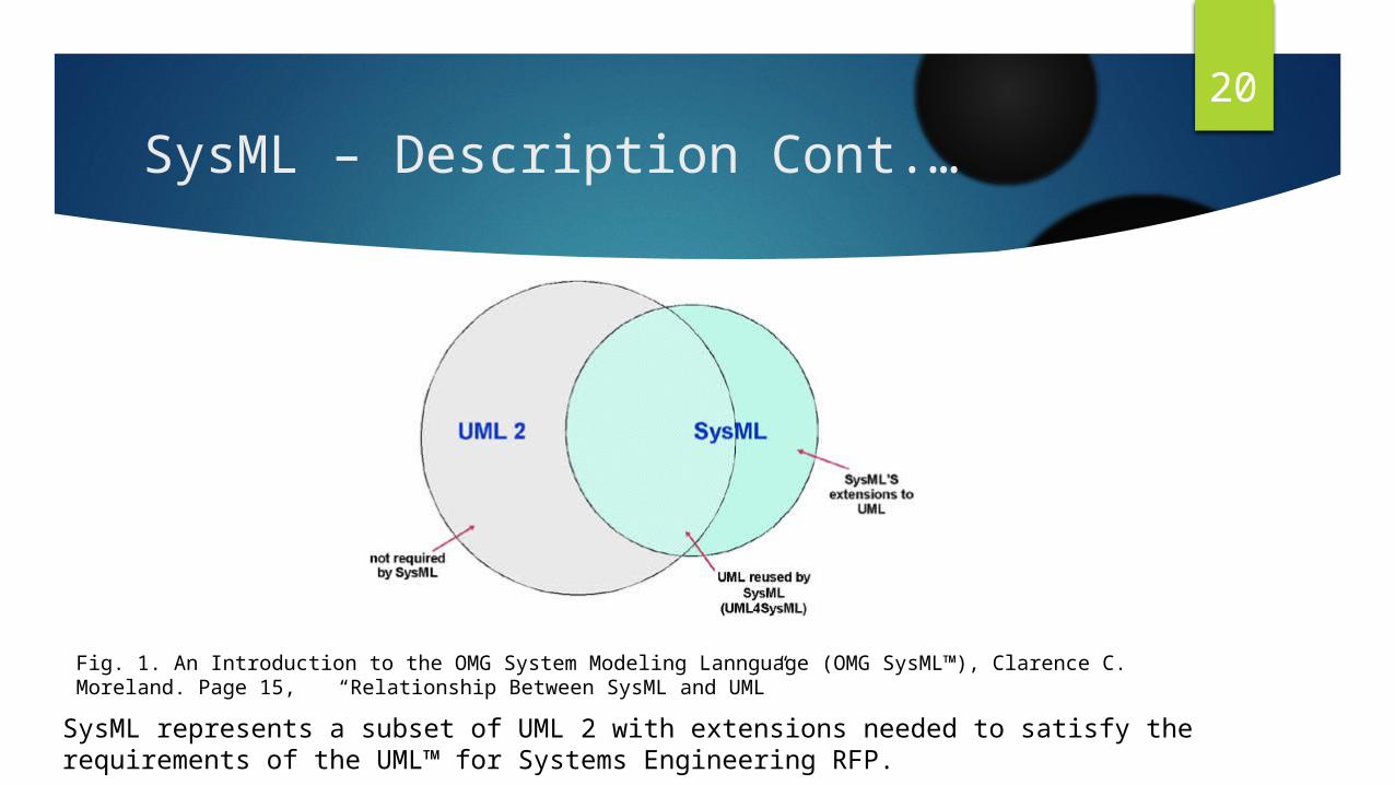
SysML represents a subset of UML 2 with extensions needed to satisfy the requirements of the UML™ for Systems Engineering RFP.
Fig. 1. An Introduction to the OMG System Modeling Lannguage (OMG SysML™), Clarence C. Moreland. Page 15, “Relationship Between SysML and UML”

21SysML - Purpose
If you are a Systems Engineering and want to improve the precision and efficiency of your communications with fellow Systems Engineers and other system and business stakeholders, then SysML is an excellent choice for a lingua franca. (If on the other hand, you are a Software Developer or a Business Analyst who wants to improve communications with your peers and other system stakeholders, then UML or BPMN may be better choices.) Here's a list of reasons why Systems Engineers may want to use SysML and a Model-Based Systems Engineering approach for their work: Facilitate communication among various stakeholders across the System Development Life Cycle Capture and manage corporate Intellectual Property related to system architectures, designs, and processes Compare and contrast “As Is” and “To Be” solutions Provide scalable structure for problem solving Furnish rich abstractions to manage size and complexity Explore multiple solutions or ideas concurrently with minimal risk Detect errors and omissions early in System Development Life Cycle [5]

22Purpose of SysML
Fig.2. An Introduction to the OMG Systems Modeling Language(OMG SysML™), Clarence C. Moreland Page 5 , “Purpose of SysML”.

23SysML Taxonomy of Diagrams
Fig.3. OMG SysML™, v1.4 Page 187, http://www.omg.org/spec/SysML/1.4/PDF.
24Requirements Diagram
Requirements Diagram is used to model the system requirements. 1. Statement of a customer needs and expectations.2. Describes the essential characteristics of the customer goals3. Requirements should be problem based and not describe the solution.
However, if there are solution based elements in the requirements, these must be modelled and included in the solution. [6]

25Requirements Diagram
A requirement “specifies a capability or condition that must (or should) be satisfied” [SysML]• Can specify function to be performed or performance criteria to be met• Basic attributes of a Requirement– ID: A unique identifier for the Requirement– Text: A Description of what is Required.• Users can create stereotypes and tags to add specific properties, e.g.– Requirement type (Performance, Safety, Functional, etc.)– Criticality– Test method– Status– Etc. [6]
Fig.4. An Introduction to the OMG Systems Modeling Language(OMG SysML™), Clarence C. Moreland Page 26 , “Requirements”.

26SysML Requirement Diagram Elements
Fig.5. An Introduction to the OMG Systems Modeling Language(OMG SysML™), Clarence C. Moreland Page 27 , “SysML Requirements DiagramElements”.

27Block Definition Diagram
SysML provides a basic structural element called Block, whose aim is to provide a discipline-agnostic building block for systems. Blocks can be used to represent all types of system components; e.g., functional, physical, human, etc. Blocks assemble to form architectures that represent how different elements in the system coexist. [7]
The SysML Block Definition Diagram (BDD) is the simplest way to describe the structure of the system. It is used to represent the system decomposition using, for example, associations and composition relationships. [7]

28Purpose of Blocks
Provides a unifying concept to describe the structure of anelement or system– Hardware– Software– Data– Procedure– Facility– Person
Multiple compartments can describe the blockcharacteristics– Properties (parts, references, values)– Operations– Constraints– Allocations to the block (e.g. activities)– Requirements the block satisfies[6] 1
Fig.6. An Introduction to the OMG Systems Modeling Language(OMG SysML™), Clarence C. Moreland Page 33 , “Blocks are Basic Structural Elements”.

29Using Blocks
• Block definition diagram (BDD) describes the relationship among blocks (e.g., composition, association, classification)
• Internal block diagram (IBD) describes the internal structure of a block in terms of its properties and connectors
• Behavior can be allocated to blocks [6]
30Block Definition Diagram Example
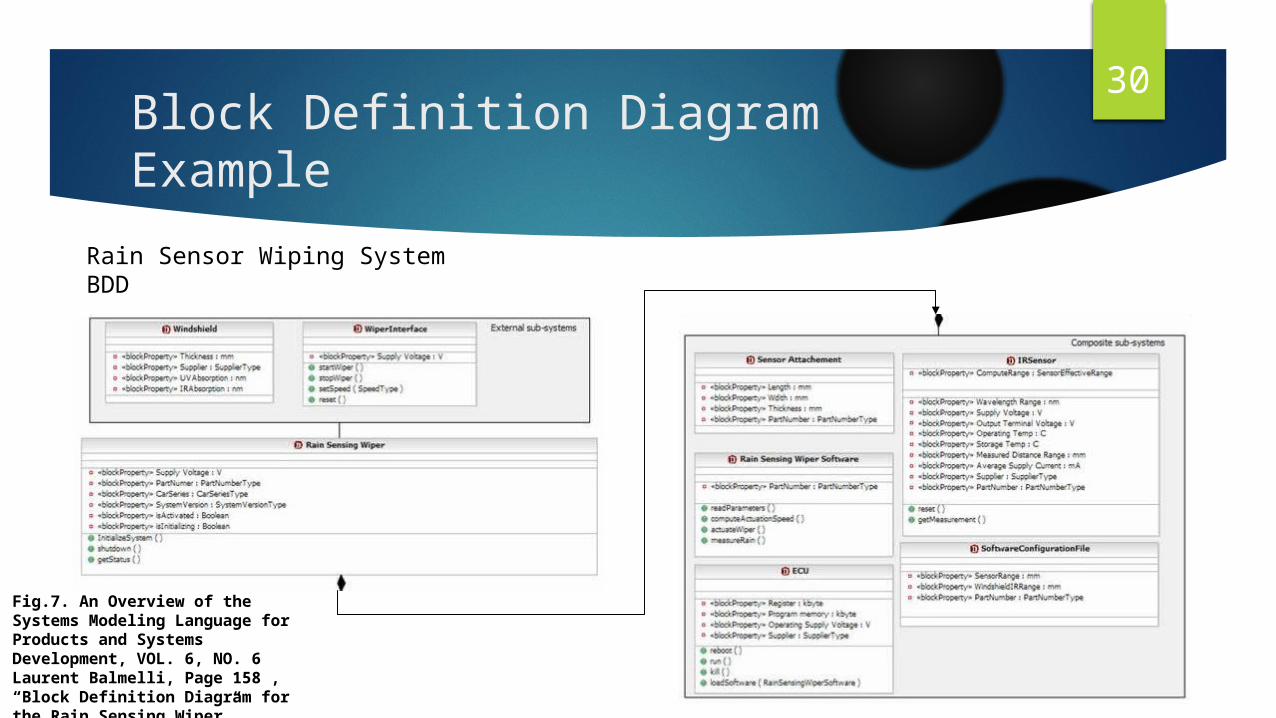
Rain Sensor Wiping System BDD
Fig.7. An Overview of the Systems Modeling Language for Products and Systems Development, VOL. 6, NO. 6 Laurent Balmelli, Page 158 , “Block Definition Diagram for the Rain Sensing Wiper”.

31Internal Block Diagram Example
Fig.8. An Introduction to the OMG Systems Modeling Language(OMG SysML™), Clarence C. Moreland Page 47 , “IBD for Distiller”.

32Parametric Diagram
Used to express constraints (equations) between value properties– Provides support for engineering analysis(e.g., performance, reliability)
• Constraint block captures equations– Expression language can be formal (e.g., MathML, OCL) or informal– Computational engine is defined by applicable analysis tool and notby SysML
• Parametric diagram represents the usage of the constraints in ananalysis context– Binding of constraint usage to value properties of blocks (e.g.,vehicle mass bound to F= ma) [6]

33Example for Constraint Block
Fig.9. An Introduction to the OMG Systems Modeling Language(OMG SysML™), Clarence C. Moreland Page 140 , “Constraint Blocks”.
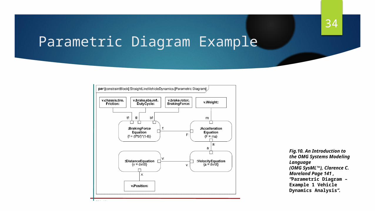
34Parametric Diagram Example
Fig.10. An Introduction to the OMG Systems Modeling Language(OMG SysML™), Clarence C. Moreland Page 141 , “Parametric Diagram – Example 1 Vehicle Dynamics Analysis”.
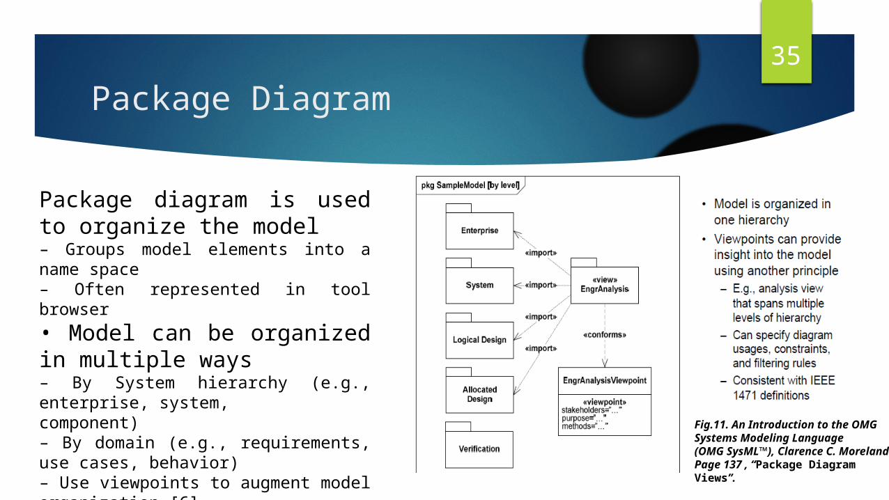
35Package Diagram
Package diagram is used to organize the model– Groups model elements into a name space– Often represented in tool browser• Model can be organized in multiple ways– By System hierarchy (e.g., enterprise, system,component)– By domain (e.g., requirements, use cases, behavior)– Use viewpoints to augment model organization [6]
Fig.11. An Introduction to the OMG Systems Modeling Language(OMG SysML™), Clarence C. Moreland Page 137 , “Package Diagram Views”.

36Package Diagram Examples
Fig.12. An Introduction to the OMG Systems Modeling Language(OMG SysML™), Clarence C. Moreland Page 136 , “Package Diagram Organizing the Model”.
37Activity Diagram
“Activity modelling emphasizes the inputs, outputs, sequences,and conditions for coordinating other behaviors.” (SysML)– ‘behavior’ as in something the system does– describes flow of activity and data– can link activity elements to owning block
Useful for the following purposes:– Exploring system functionality– Human/subsystem communication modelling– Data/item flow modelling– General flow of control modelling [6]

38Activity Diagram Example
Fig.13. An Introduction to the OMG Systems Modeling Language(OMG SysML™), Clarence C. Moreland Page 75 , “Pin vs. Object Node Notation”.
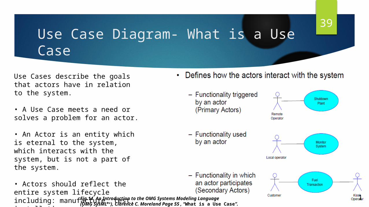
39Use Case Diagram- What is a Use Case
Use Cases describe the goals that actors have in relation to the system.
• A Use Case meets a need or solves a problem for an actor.
• An Actor is an entity which is eternal to the system, which interacts with the system, but is not a part of the system.
• Actors should reflect the entire system lifecycle including: manufacture, test, installation, maintenance, etc.[6]
1Fig.14. An Introduction to the OMG Systems Modeling Language(OMG SysML™), Clarence C. Moreland Page 55 , “What is a Use Case”.

40Use Case Diagram Example
Fig.15. An Overview of the Systems Modeling Language for Products and Systems Development, VOL. 6, NO. 6 Laurent Balmelli, Page 155 , “SysML Use Case Diagram”.

41Sequence Diagrams
Sequence Diagrams are created for two reasons:– Understanding the requirements in more detail by creating a model of the end-users problems (Modelling the Problem)
– Typically however, after defining an initial System Architecture and exploring the capabilities of the system (captured as Use Cases) you’ll want to see how the capabilities are delivered by the components within the System Architecture (Modelling the Solution). [6]
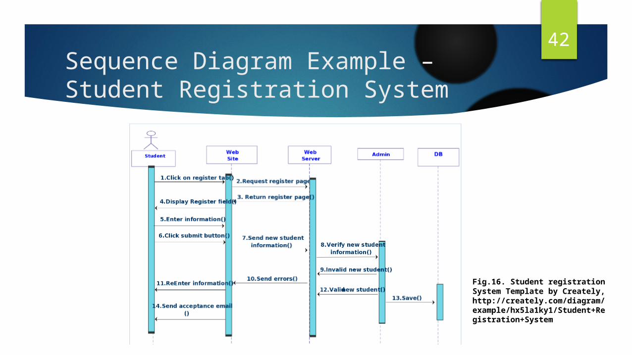
42Sequence Diagram Example – Student Registration System
Fig.16. Student registration System Template by Creately, http://creately.com/diagram/example/hx5la1ky1/Student+Registration+System

43Refinement through Iteration
Fig.17. An Introduction to the OMG Systems Modeling Language(OMG SysML™), Clarence C. Moreland Page 101 , “Refinement through Iteration”.

44System State Machines
Defines:
• High level operational states of the system
• How the system as a whole reacts to the various external events that it can receive
• Failure conditions and circumstances under which the system can recover
• Cross references system capabilities in terms of Use Case availability for a system state
• Defines pre- and post-conditions for high-level use cases
• System functions which should be mutually exclusive[6]

45State Machine Diagram
Fig.18. An Introduction to the OMG Systems Modeling Language(OMG SysML™), Clarence C. Moreland Page 114 , “A Simple Example”.

46Relationship with System Engineering
During the last decade SysML has evolved into enabling modeling for Model-Based Systems Engineering (MBSE), a Systems Engineering paradigm that emphasizes the application of rigorous visual modeling principles to Systems Engineering activities throughout the System Development Life Cycle (SDLC). These Systems Engineering activities include, but are not limited to requirements analysis and verification, architectural analysis and allocations, performance analysis, trade studies, and system architecture specification.
SysML standards are used to specify the System Architecture Model and to serve as a common language among Systems Engineers and other stakeholders (Software Engineers, Electrical Engineers, Mechanical Engineers, Customers, etc.)
SysML ensures that the System Architecture Model is requirements-driven to the extent that all model elements combine traditional Systems Engineering best practices with visual modeling best practices.
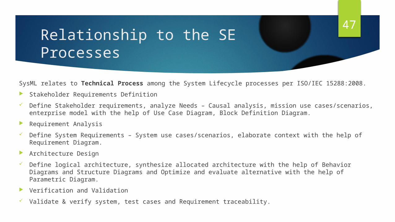
47Relationship to the SE Processes
SysML relates to Technical Process among the System Lifecycle processes per ISO/IEC 15288:2008. Stakeholder Requirements Definition Define Stakeholder requirements, analyze Needs – Causal analysis, mission use cases/scenarios,
enterprise model with the help of Use Case Diagram, Block Definition Diagram. Requirement Analysis Define System Requirements – System use cases/scenarios, elaborate context with the help of
Requirement Diagram. Architecture Design Define logical architecture, synthesize allocated architecture with the help of Behavior Diagrams and
Structure Diagrams and Optimize and evaluate alternative with the help of Parametric Diagram. Verification and Validation Validate & verify system, test cases and Requirement traceability.

48Application of SysML to Millennium Systems
We use SysML to create a blueprint to guide us through each of the life cycle stages involved from inception to final production of the SPIRIT phone.
Primarily used in the technical process to bring out the stakeholder requirements, use case scenarios for SPIRIT phone, identifying verification and validation criteria, test cases and finally establishing traceability between the architecture and the requirements.
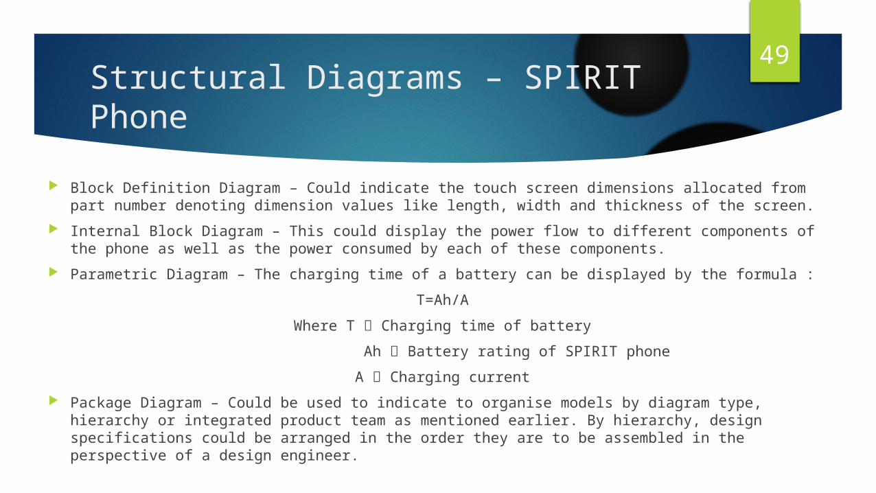
49Structural Diagrams – SPIRIT Phone
Block Definition Diagram – Could indicate the touch screen dimensions allocated from part number denoting dimension values like length, width and thickness of the screen.
Internal Block Diagram – This could display the power flow to different components of the phone as well as the power consumed by each of these components.
Parametric Diagram – The charging time of a battery can be displayed by the formula :T=Ah/A
Where T Charging time of battery Ah Battery rating of SPIRIT phone
A Charging current Package Diagram – Could be used to indicate to organise models by diagram type, hierarchy or
integrated product team as mentioned earlier. By hierarchy, design specifications could be arranged in the order they are to be assembled in the perspective of a design engineer.

50Behaviour Diagrams – SPIRIT Phone
Activity Diagram – This might chart the detailed activity program for the assembly line of the production unit.
Sequence Diagram – Could indicate the success or failure scenario of a user playing music on the SPIRIT phone. The success scenario would be similar to the use case diagram sequence where as a failure scenario would contain multiple iterations performed in order to achieve a successful scenario.
State Machine Diagram – As mentioned earlier, there are 3 states:1. Deactivated – Phone waits for the user to play a track activating the command.2. Initializing – When the signal is received, it transitions to “Initializing” state.3. Activated – When the task is successfully completed, the phone transitions to “Activated”
state.

51Use Case Diagram – Spirit Phone
Play Music Audio Player
Speaker
Unlock Phone
<<include>>
<<include>>
<<allocated>>
<<include>>
<<allocated>>
<<allocated>><<allocated>>
<<allocated>>
Sound Output<<include>>
Actor
Fig. 19. Use case Diagram for Spirit Phone

52Use Case Diagram – Spirit Phone
An example for Use Case Diagram is shown indicating procedural method of how a user would play music on the SPIRIT phone.
The user is termed as an “Actor” in the Use Case Diagram. Each use case represents a goal that is necessary to run in order to
perform the final function.

53Requirement Diagram – Spirit Phone
<<requirement>>
REQ_A1
The phone shall open an aplication in 2 secondsFunction
<<requirement>>
REQ_A1.1
The phone shall have a Quadcore 1.2 GHz ProcessorPerformance :
<<requirement>>
REQ_A1.2
The phone shall have a Ram of 2 GBPerformance
Model Element Memory<<Refine>>
Model Element Qualcomm MSM 8226 Snapdragon 400<<verify>>
<<requirement>>
REQ_A1.1
The phone shall have a chip set compatible with Quadcore 1.2 GHz ProcessorPerformance :
<<DeriveReqt>>Model Element Cortex A7
Quadcore 1.2 GHz<<trace>>
Fig. 20. Requirement Diagram for Spirit Phone

54Requirement Diagram – Spirit Phone
An example for requirement diagram using “The phone shall open an application in 2 seconds” is shown which is further broken down into 2 sub requirements:
1. The phone shall have a 1.2GHz Quadcore Processor.2. The phone shall have a RAM of 2GB.
The first sub requirement has lead to a derived requirement, “The phone shall have a chipset compatible with 1.2GHz Quadcore Processor

55Backup Slide - Part 1 SEBoK Introduction
Articles included in this part:• Systems Engineering Overview• Economic Value of Systems Engineering• Systems Engineering: Historic and Future Challenges• Systems Engineering and Other Disciplines• Scope of the SEBoK• Structure of the SEBoK• SEBoK Users and Uses• Use Cases: Practicing Systems Engineers, Other Engineers, Customers
of Systems Engineering, Educators and Researchers, General Managers [1]

56Backup Slides - Part 2 Foundations of SystemsArticles included in this part:• Systems Fundamentals• What is a System• Types of Systems• Groupings of Systems• Complexity, Emergence, Systems Science, History of Systems Science, Systems Approaches,
Systems Thinking, What is Systems Thinking ,Concepts of Systems Thinking, Principles of Systems Thinking, Patterns of Systems Thinking, Representing Systems with Models, What is a Model, Why Model, Types of Models, System Modeling Concepts, Integrating Supporting Aspects into System Models, Modeling Standards, Systems Approach Applied to Engineered Systems, Overview of the Systems Approach, Engineered System Context, Identifying and Understanding Problems and Opportunities, Synthesizing Possible Solutions, Analysis and Selection between Alternative Solutions, Implementing and Proving a Solution; Deploying, Using, and Sustaining Systems to Solve Problems; Stakeholder Responsibility, Applying the Systems Approach [1]
57Backup Slides - Part 3 SE and Management
Articles included in this part:• Introduction to Life Cycle Processes• Generic Life Cycle Model• Applying Life Cycle Processes• Life Cycle Processes and Enterprise Need• Life Cycle Models, System Life Cycle Process Drivers and Choices, System Life Cycle Process
Models: Vee, System Life Cycle Process Models: Iterative, Integration of Process and Product Models, Lean Engineering, Concept Definition, Business or Mission Analysis, Stakeholder Needs and Requirements, System Definition, System Requirements, System Architecture, Logical Architecture Model Development, Physical Architecture Model Development, System Design, System Analysis, System Realization, System Implementation, System Integration, System Verification, System Validation, System Deployment and Use, System Deployment, Operation of the System, System Maintenance, Logistics [1]

58Backup Slides - Part 4 Applications of Systems Engineering
Articles included in this part:• Product Systems Engineering• Product Systems Engineering Background• Product as a System Fundamentals• Business Activities Related to Product Systems Engineering• Product Systems Engineering Key Aspects, Product Systems Engineering Special Activities,
Service Systems Engineering, Service Systems Background, Fundamentals of Services, Properties of Services, Scope of Service Systems Engineering, Value of Service Systems Engineering, Service Systems Engineering Stages, Enterprise Systems Engineering, Enterprise Systems Engineering Background, The Enterprise as a System, Related Business Activities, Enterprise Systems Engineering Key Concepts, Enterprise Systems Engineering Process Activities, Enterprise Capability Management, Systems of Systems (SoS), Architecting Approaches for Systems of Systems, Socio-Technical Features of Systems of Systems, Capability Engineering [1]

59Backup Slides - Part 5 Enabling Systems Engineering
Articles included in this part:• Enabling Businesses and Enterprises• Systems Engineering Organizational Strategy• Determining Needed Systems Engineering Capabilities in Businesses and
Enterprises• Organizing Business and Enterprises to Perform Systems Engineering• Assessing Systems Engineering Performance of Business and Enterprises• Developing Systems Engineering Capabilities within Businesses and Enterprises,
Culture, Enabling Teams, Team Capability, Team Dynamics, Technical Leadership in Systems Engineering, Enabling Individuals, Roles and Competencies, Assessing Individuals, Developing Individuals, Ethical Behavior [1]

60Backup Slides - Part 6 Related Disciplines
Articles included in this part:• Systems Engineering and Software Engineering• The Nature of Software• An Overview of the SWEBOK Guide• Key Points a Systems Engineer Needs to Know about Software Engineering, Key Points a Systems
Engineer Needs to Know about Managing a Software Team, Systems Engineering and Project Management, The Nature of Project Management, An Overview of the PMBOK Guide, Relationships between Systems Engineering and Project Management, The Influence of Project Structure and Governance on Systems Engineering and Project, Management Relationships, Systems Engineering and Industrial Engineering, Systems Engineering and Procurement/Acquisition, Systems Engineering and Specialty Engineering, Integration of Specialty Engineering; Reliability, Availability, and Maintainability; Human Systems Integration; Safety Engineering; Security Engineering; System Assurance, Electromagnetic Interference/Electromagnetic Compatibility, Resilience Engineering, Manufacturability and Producibility, Affordability, Environmental Engineering [1]

61Backup Slides - Part 7 SE Implementation Examples
Articles included in this part:• Matrix of Implementation Examples• Case Studies• Successful Business Transformation within a Russian Information Technology
Company• Federal Aviation Administration Next Generation Air Transportation System• How Lack of Information Sharing Jeopardized the NASA/ESA Cassini/Huygens Mission to
Saturn, Hubble Space Telescope Case Study, Global Positioning System Case Study, Global Positioning System Case Study II, Medical Radiation Case Study, FBI Virtual Case File System Case Study, MSTI Case Study, Next Generation Medical Infusion Pump Case Study, Design for Maintainability, Complex Adaptive Operating System Case Study, Vignettes, Denver Airport Baggage Handling System Vignette, Virginia Class Submarine Vignette, UK West Coast Route Modernisation Project Vignette, Singapore Water Management Vignette, FAA Advanced Automation System (AAS) Vignette, Standard Korean Light Transit System Vignette. [1]

62Backup Slides - SysML - An overview including history
Modeling is the designing of software applications before coding. Modeling is an Essential Part of large software projects, and helpful to medium and even small projects as well. A model plays the analogous role in software development that blueprints and other plans (site maps, elevations, physical models) play in the building of a skyscraper. Using a model, those responsible for a software development project's success can assure themselves that business functionality is complete and correct, end-user needs are met, and program design supports requirements for scalability, robustness, security, extendibility, and other characteristics, before implementation in code renders changes difficult and expensive to make. [3]UML (Unified Modeling Language) is a standard notation for the modeling of real-world objects as a first step in developing an object-oriented design methodology. [3]

63Backup Slides - Purpose of SysML
Improved communications Assists in managing complex system development Separation of concerns Hierarchical modeling Incremental development & evolutionary acquisition Improved design quality Reduced errors and ambiguity More complete representation Early and on-going verification & validation to reduce risk Other life cycle support (e.g., training) Enhanced knowledge capture [6]

64Backup Slides - The Four Pillars of SysML
Structure: This defines the system hierarchies and the interconnections between elements.
Behavior: This includes function based and state based behaviors of system elements.
Properties: This includes the parametric models which has scientific equations and formulas to define parameters.
Requirements: This includes all the requirements, the requirement hierarchy and its traceability.[6]

65Backup Slides SysML Diagram Frames
1. Each SysML diagram represents a model element2. Each SysML Diagram must have a Diagram Frame3. Diagram context is indicated in the header: - Diagram kind (act, bdd, ibd, seq, etc.) - Model element type (activity, block, interaction, etc.) - Model element name - Descriptive diagram name or view name4. A separate diagram description block is used to indicate if the diagram is complete, or has elements hidden [6]
66Backup Slides Requirement Diagram Elements
The requirement diagram shows both requirements and the different types ofrelationship that can be specified between them.Requirement properties (such as the textual description) can be shown ifrequired.Containment (sometimes referred to as ‘flowdown’) is used to show whererequirements are decomposed into sub-requirements.The «deriveReqt» and «copy» relationships can only exist betweenrequirements. «trace», «refine», «satisfy» and «verify» can exist between arequirement and any other model element.The «verify» relationship can only exist between a requirement and a behavioralmodel element stereotyped as a «testCase».An alternative to these direct relationships is to use the callout notation – onlyone example of the callout notation is shown here.«problem» and «rationale» comments can be added as required to any modelelement to capture issues and decisions.[6]

67Backup Slides - Block Property and Ports
There are three part block property types
1.Part Property: Usage of a block to reference a part.2.Reference Property: Used to indicate the logical interface between two parts.3.Value Property: Defines a value with units, dimensions, and probability distribution
SysML port specifies an interaction point on a block or a part– Supports integration of behavior and structure– Linked by a connector to one or more other ports
There are three port types:1. Standard UML port : Specifies the operations and signals of a block2. Flow Port : Specifies what flows in and out of a block. It can be unidirectional ( Atomic
Port ) and bi-directional ( Non Atomic port) [6]

68Backup Slides-Requirement Allocation to Blocks
Fig.21. An Overview of the Systems Modeling Language for Products and Systems Development, VOL. 6, NO. 6 Laurent Balmelli, Page 159 , “Example of requirement allocation”.
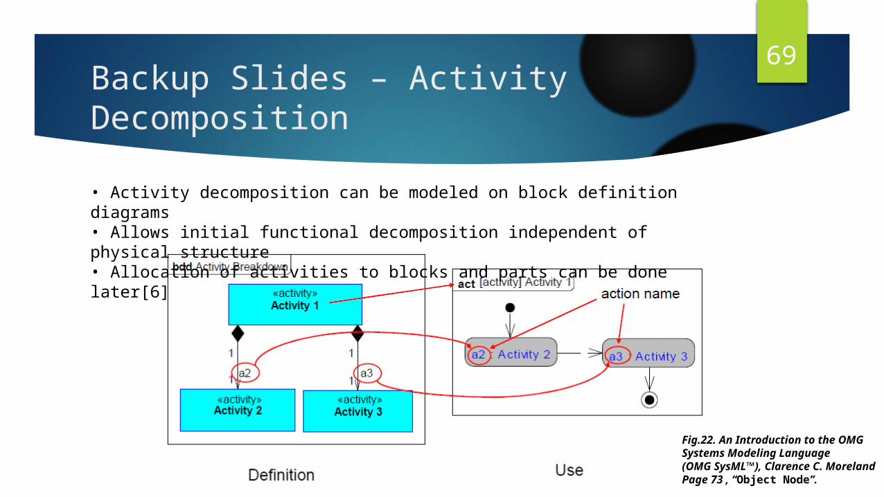
69Backup Slides – Activity Decomposition• Activity decomposition can be modeled on block definition diagrams• Allows initial functional decomposition independent of physical structure• Allocation of activities to blocks and parts can be done later[6]
Fig.22. An Introduction to the OMG Systems Modeling Language(OMG SysML™), Clarence C. Moreland Page 73 , “Object Node”.

70Backup Slides – Activity Decomposition
Fig.23. An Introduction to the OMG Systems Modeling Language(OMG SysML™), Clarence C. Moreland Page 78 , “Activity Diagram – Model ElementsControl Nodes”.
71Backup Slides – Use Case Diagram
In Use Case diagrams we make use of the parent, child use case concept where child use cases are extracted from parent use case. An example would be the battery charging system in a phone which is a parent use case from which we have wireless charging, USB charging as the child use cases.

72Backup Slides - Test Case Diagram
Test Case diagram states the tests to be conducted on an element, the testing conditions, and test constraints to verify if it is able to meet the requirements and ensure traceability. Test diagrams can be for an element or sub systems
Fig.24. An Overview of the Systems Modeling Language for Products and Systems Development, VOL. 6, NO. 6 Laurent Balmelli, Page 157 , “Requirement and Test Case Traceability”.

73Backup Slide - Sequence Diagram
The sequence diagram can result in two scenarios
1. Success scenarios– Everything goes well and the actor achieves the Use Case goal– Also called sunny day scenarios.– Defines what is supposed to happen, so that the stakeholders canagree prior to investigating everything that can go wrong.
2. Failure scenarios– Models failure conditions and their consequences.– May map to full blown Use Cases that will “extend” the main UseCase, or– may involve a simple variation on the normal sequence.
• Scenarios are expressed as interaction diagrams [6]

74Backup Slides – System State Machine
Component State Machines defines• State behavior of a «block» component• How the block and any elements typed by thatblock react to the various events they can receive• Cross references block functional capabilities tostates and events• Defines pre- and post-conditions for thesecapabilities• Defines mutually exclusive capabilities [6]
Fig.25. An Introduction to the OMG Systems Modeling Language(OMG SysML™), Clarence C. Moreland Page 113 , “Initial and Final States”.

75References
[1] BKCASE Project, Guide to the Systems Engineering Body of Knowledge (SEBoK). v1.4. (2015)[2] BKCASE Project, “SEBoK”, http://sebokwiki.org/wiki/Guide_to_the_Systems_Engineering_Body_of_Knowledge_%28SEBoK%29. wiki, Dec. 2015. Web. 8 Dec. 2015.[3] "SysML Forum." SysML FAQ: Frequently Asked Questions about SysML. Web. 8 Dec. 2015.[4]OMG Systems Modeling Language (OMG SysML™) v1.4 Page 23 - 26, http://www.omg.org/spec/SysML/1.4/PDF.[5] "FAQ." SysML.Tools: SysML Modeling Tools. Web. 8 Dec. 2015.[6]. Fig.3. An Introduction to the OMG Systems Modeling Language (OMG SysML™), Clarence C. Moreland, http://www.omg.org/news/meetings/workshops/Real-time_WS_Final_Presentations_2008/Tutorials/00-T2_Moreland.pdf[7]. Balmelli, Laurent. "An overview of the systems modeling language for products and systems development." Journal of Object Technology Vol 6, No 6 (2007): 149-177.