system engineering for industrial air pollution control · system engineering for industrial air...
TRANSCRIPT

Proceedings of Academics World 10th International Conference, Istanbul, Turkey, 11th December 2015, ISBN: 978-93-85832-62-8
41
SYSTEM ENGINEERING FOR INDUSTRIAL AIR POLLUTION CONTROL
MOHAMED. A. SAAD
National Research Centre, Textile Engineering Department, 33 EL Bohouthst.
(former: El Tahrirst.) –Dokki – Giza – Egypt, P.O.B.12622
Abstract—The paper represents a case study regarding the conversion of Electro-Static Precipitators (ESP`s) into Fabric Filters (FF). Seven cement production companies were established in Egypt during the period 1927 to 1980 and 6 new companies were established to cope with the increasing cement demand in 1980, s. the cement production market share in Egypt indicate that there are six multinational companies in the local market, they are interested in the environmental conditions improving and so decided to achieve emission reduction project. Methods to mitigate dust emissions in Egyptian cement plants are presented with a special focus on converting the Electrostatic Precipitators(ESP`s) into Fabric Filters(FF)using the same ESP casing, bottom hoppers, dust transportation system and ESP ductwork .Only, the fan system for the higher pressure drop with the fabric filter was replaced. The proper selection of bag material was a prime factor with regard to gas composition, temperature and particle size. Fiberglass with PTFE membrane coated bags was selected. This fabric is rated for a continuous temperature of 250 C and a surge temperature of 280C.The dust emission recorded was less than 20 mg/m3 from the production line fitted with fabric filters which is super compared with the ESP`s working lines stack.
Keywords—Engineering, Electrostatic Precipitator, Filtration, Dust Collectors, Filter Fabrics, Membrane, Cement, Filter Efficiency.
I. INTRODUCTION During the 90s, 6 new cement companies were established to cope with the increasing construction activity and the resulting increasing cement demand In 2008, local cement consumption reached 38.4mn tons and the capacity 43.3 million tons Egypt’s cement industry is still growing strong, additional 18 million tons production capacity increase is expected during the coming 3 years the cement production market shares indicate that there are 6 Multinational Companies in the local market, they are interested the environmental conditions improving and so allocated considerable budget to achieve the emission reduction projects. Fig (1) shows the chronological establishment of cement producing companies in Egypt.
Fig.1 the major cement content companies established during
the period 1927 to late 70,s and 80,s
Traditionally, filter fabrics are tested and examined for physical and mechanical properties subsequent to usage and application in a typical industry. Nevertheless, it is more important to measure the filter performance in terms of air permeability, filtration efficiency, cleaning efficiency and pressure drop. . From the practical point of view, the fabrics having
particular air permeability and filtration efficiency may be used in a particular type of industry. Early investigations by Georgy [1],Marsh Mac[2],Barr [3] and Lamb [4] show that air permeability of different materials and fabrics used with gaseous and liquid media were measured using different methods, e.g., by drawing air through filter fabrics via suction fans or compressed air, and then measuring the pressure drop using water manometers or gas meters. Different filtration apparatus were described in previous literature by Lamb [5], Lgwe [6], Chatterjee [7] and Saad et.al [8]-[13]. However, the main parameters influencing the filtration efficiency of the filter media are deduced from different variables, which are as follows: Cement plant stack dust emission Due to high emissions, the production lines are interrupted at a rate 150 stopping hours per year on the average. Table (1) shows maximum limit for emissions and amendment of the law to be applied within the coming two years.
TABLE I
LIMITS OF EMISSIONS AND METHOD ACCORDING TO EGYPT ENVIRONMENTAL LAW 4/94

System Engineering for Industrial Air Pollution Control
Proceedings of Academics World 10th International Conference, Istanbul, Turkey, 11th December 2015, ISBN: 978-93-85832-62-8
42
Fig.2 Method of recording dust emissions
Basically The collected dust is returned back to the process (except the bypass dust) increasing productivity and result in energy savings, Fig (2) shows method recording dust emissions. According to the rates of emissions recorded for both kinds of filters,Cairo&Helwan governorates receive around 20.000 tons/year ( if the main EP is stopped for 4hours/day) as solid pollutant. Fig (3) shows a comparison of emission rate for both ESP`s and fabric filters. The values given and calculation was based on cement production line of one million ton per annum capacity.
Fig.3 Comparison for dust emission of both kinds of filters
Fig (4) shows a schematic diagram of ESP with details of outer and inner parts. The mechanism of dust collection via ESP is shown in fig (5).
Fig.4 Mechanism of dust collection via ESP.
Fig.5 Schematic diagram of Electrostatic Precipitator
Electrons are emitted from discharge electrodes which have been charged with a rectified negative high voltage. These electrons migrate to the collecting electrodes. As the electrons accumulate on the dust particles, the latter become negatively charged. The electric field transports them to the earthed collecting electrodes where they are deposited. Fig 6(a) shows a schematic diagram of filter fabric and fig 6 (b) shows the pulse jet cleaning system, and the mechanism of pulse jet cleaning principle is shown in fig 6(C). It is worthy noted that repeated filtering and cleaning cycles are counted about 3 million times until the fabric bag is worn away based on 3 minutes intervals of cleaning cycles.
Fig.6 (a) Schematic diagram of fabric filter.
In fabric filters the gas carrying dust is forced to pass through fabric elements that can be shaped in cylinder (bags) or pannels.The dust layer over the fabric surface collaborates to dust collection and in some application helps to protect the surface of the fabric from moisture or chemical attack. Filtering elements

System Engineering for Industrial Air Pollution Control
Proceedings of Academics World 10th International Conference, Istanbul, Turkey, 11th December 2015, ISBN: 978-93-85832-62-8
43
are periodically cleaned by a proper cleaning system. Filtering velocity and fabric pressure drop are calculated according to equations (1) & (2): Filtering velocity:
Fig.6 (b) Pulse-jet cleaning system.
Fig.6(c) Pulse jet cleaning principle.
Needle felt fabric bags development and production in Egypt in 1994 was the milestone for the local manufacturing of Fabric Filters. Until the year 1994, all fabric bags (the filter media) was imported at high prices, moreover technical specifications were not identified, due to this it had shorter operational lifetime. II. EXPERIMENTAL WORK A. ESP`s in series at Suez&Kattameya cement plants: In Kattameya and Suez ESPs in series were installed in 2005 but after two years of operation the emission
targeted for 50 mg/m3 is still close to 100 mg/m3 with some peaks above the 200 mg/m3 and still the two production lines suffer interruptions due to high emissions, this is shown in fig. 7.
Fig.7 ESP in series – Suez plant
B. Conversion of ESP into fabric filter methodology The following items were adopted to achieve the method of conversion
▪ Using the same ESP Casing ▪ Using the same ESP Dust hoppers ▪ Using the same ESP Dust Transportation
System in most cases ▪ Using the same ESP Ductwork ▪ Replacing the fan system for the higher
pressure drop with the FF Connecting compressed air pipes for bags cleaning system. Power consumption will remain the same to achieve the low dust emission An important consideration is the selection of bag material. Gas Temperature and gas conditions are major factors in this decision.
C. Steps of Converting ESP to FF Five steps are followed to convert the ESP to Fabric Filter; these are shown in figs (8) to (24).
Fig.8 Step No.1-Cut the ESP roof.
Fig.9 Step No.2-Strip off the ESP Internals.

System Engineering for Industrial Air Pollution Control
Proceedings of Academics World 10th International Conference, Istanbul, Turkey, 11th December 2015, ISBN: 978-93-85832-62-8
44
Fig.10 Collecting plates of ESP removed out.
Fig.11 Step No.3-Install new gas plenum
Fig.12 Step No.4–Replace old ID fan
Fig.13 Step No.5–Adjusting filter bags
The Stack of the Assuit Cement Plant with low dust emission less than 20 mg/m3 from the line was fitted with FF, meanwhile the ESP working lines stack emission is viewed and considered good performing, and this is shown in fig (14). The converted bypass ESP after erection in its final place is shown in fig (15). A comparison between ESP of line9 and converted ESP of line8 in Torah Co. is shown in fig (16).
Fig.14 Comparison between ESP stacks and converted
ESP into FF stack in Assiut Cement Company
Fig.15 The converted bypass filter after conversion into FF
inTourah cement Co. (December2011).
Fig.16 Comparison between ESP of line9 and converted ESP of
line8 in Torah Co.
Table 2 Data for Torah Line 8 main ESP to FF conversion as the first kiln and Raw Mill ESP
conversion case in Egypt within EPAP II
D. Design Considerations of pulse jet filters in Torah This bag filter utilized an online pulse jet system, which is the highest level of technology available. The pulse jet system is more advanced and offers far superior performance compared to reverse air bag

System Engineering for Industrial Air Pollution Control
Proceedings of Academics World 10th International Conference, Istanbul, Turkey, 11th December 2015, ISBN: 978-93-85832-62-8
45
filters, or electrostatic precipitators. The principle of the pulse jet system is as follows: The filter employs cylindrical filter bags and is cleaned on demand by the reverse pulse jet principle. Dust laden air enters the bag chamber via a specially designed side inlet and existing dropout chamber, which allows large dust particles to settle out due to the reduction in velocity and change of direction and drop directly into the dust collecting hopper. This also serves to protect the filter bags against impact from large particles. The dust is collected on the outside of the bag, while the clean air passes through the filtration medium. The clean air is then drawn up the center of the bag and into the clean air plenum. The dust, which builds up on the surface of the bag, forms a ‘cake’ and inhibits airflow. At this stage the differential pressure becomes too high and the cleaning sequence is commenced. The dust cake is removed from the filter bags by the introduction of compressed air to each row of filter bags in turn. This compressed air expands the bag and cracks the cake from the surface of the bag. The cake is then heavy enough to fall into the collection hopper. This cleaning action is enhanced by a venturi located in the neck of each filter bag support cage, which induces a secondary airflow. Each compartment is arranged into rows, with each row having 14 bags. Each row will have its own pulse pipe and a 2.5” from AUTEL pulse valve. Within each row, the bags are spaced at 255mm centers, with the bags 300mm (center line) from the compartment wall. This will result in a can velocity of 1.1m/s. The can velocity is a critical factor for the filter bags life. The system supplied can be used as a high pressure system. The walk-on clean air plenum with penthouse allows for easy inspection and convenient bag replacement, even in inclement weather. The bags are inserted and removed via the walk on plenum and can be fitted by one person. The top of the bag has a stainless steel snap band sewn into heavy felt and snaps into circular holes in the tube sheet. The cage, with integral venturi, is simply lowered into the bag–no bolts, screws or fasteners are required. Fiberglass with PTFE membrane for the bags was selected. This fabric is rated for a continuous temperature of 250 C and a surge temperature of 280 C. It achieved emissions of less than 25 mg/m3, and a bag life of 3 years.
E. Bags needed to be changed if the following occurs
1. Bags are punctured or worn through 2 .Bags are blinded and pressure drop is too high
Once either of the above occurs the bags need to be changed. Firstly the pulse pipe must be disconnected and placed to one side. Then the cage is removed, by first lifting up the cage so that all the top section and 200mm of the bottom section are exposed above the bag. The top section is then removed from the bottom
section. The bottom section can then be lifted away from the bag. Once done the 2 cage sections can be placed to one side in the compartment or placed outside depending on the number of bags being changed. The bag is then removed, folded in thirds and taken outside and preferably dropped through a chute to an enclosed bin. The area around the removed bag must then be cleaned with a brush so that any dust present drops into the hopper (and does not fall into the neighboring bags) A new bag is inserted and snapped into the tube sheet. The bottom cage section is lowered into the bag until only the last 2 rings are visible (approx 200mm). The top section is then placed onto the bottom section at a 30 degree angle. It is then raised vertical and locked into place with the bottom section. The entire cage is then lowered into the bag. The pulse pipe can then be reattached. Once the compartment has been sealed, the dampers can deactivated and gas can again pass into that compartment. Figs (17), 18), and (19) show the steps for correct installation of the bag into the tube sheet.
Fig.17 installing the bag into the tube sheet.
Fig.18 Incorrectly installed bag.
Fig.19 Correctly installed bag.
The cage is manufactured in 2 sections. It has 20 longitudinal wires manufactured in a 4 mm carbon steel wire. It has support rings spaced every 200mm; these rings are constructed from a 4mm carbon steel
System Engineering for Industrial Air Pollution Control
Proceedings of Academics World 10th International Conference, Istanbul, Turkey, 11th December 2015, ISBN: 978-93-85832-62-8
46
wire. The surface of the cage wires must have no sharp edges that can damage the bag. The top section of the cage has a venturi, which is manufactured from a 1.2mm KCR material. The purpose of the venturi is to guide and increase the velocity of the pulsed air into the bag to ensure complete bag cleaning. This venturi is welded in and cannot be removed, thereby saving time during installation and change outs. The bottom section has a bottom cap manufactured from 1mm carbon steel. The cage is joined by means of a “Rotating joint.” The cage does not require a clamp as it has an in built venturi that sits on the tube sheet around the bag, fig (20) shows a cage being installed into a bag.
Fig.20 Cage being installed into a bag.
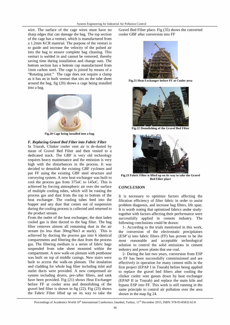
F. Replacing Gravel Bed Filter into Fabric Filter In Tourah, Clinker cooler vent air is de-dusted by mean of Gravel Bed Filter and then vented to a dedicated stack. The GBF is very old technology requires heavy maintenance and the emission is very high with the disturbances in the process. It was decided to demolish the existing GBF cyclones and put FF using the existing GBF steel structure and conveying system. A new heat exchanger was built to cool the process gas from 375oC to 145oC. This is achieved by forcing atmospheric air over the surface of multiple cooling tubes, which will be routing the process gas and dust from the top to bottom of the heat exchanger. The cooling tubes feed into the hopper and any dust that comes out of suspension during the cooling process is collected and returned to the product stream. From the outlet of the heat exchanger, the dust laden cooled gas is then ducted to the bag filter. The bag filter removes almost all remaining dust in the air stream (to less than 30mg/Nm3 at stack). This is achieved by ducting the process gas into 6 identical compartments and filtering the dust from the process gas. The filtering medium is a series of fabric bags suspended from tube sheet mounted within the compartment. A new walk-on plenum with penthouse was built on top of middle casings. New stairs were built to access the walk-on plenum. The insulation and cladding for whole bag filter including inlet and outlet ducts were provided. A new compressed air system including dryers, pre-/after filters, and tank have been provided. Fig (21) shows Heat Exchanger before FF at cooler area and demolishing of the gravel bed filter is shown in fig (22). Fig (23) shows the Fabric Filter lifted up on its way to take the
Gravel Bed Filter place. Fig (35) shows the converted cooler GBF after conversion into FF
Fig.21 Heat Exchanger before FF at Cooler area
Fig.22 Demolishing of the Gravel Bed Filter
Fig.23 Fabric Filter is lifted up on its way to take the Gravel
Bed Filter place CONCLUSION It is necessary to optimize factors affecting the filtration efficiency of filter fabric in order to assist problem diagnosis, and increase bag filters, life span. It is worth noting that optimized fabrics under study-together with factors affecting their performance were successfully applied in cement industry. The following conclusions could be drawn:
1- According to the trials mentioned in this work, the conversion of the electrostatic precipitators (ESP`s) into fabric filters (FF) has proven to be the most reasonable and acceptable technological solution to control the solid emissions in cement industry and power plants that use coal.
2- During the last two years, conversion from ESP to FF has been successfully commissioned and are effectively in operation for many cement mills in the first project (EPAP I in Tourah) before being applied to replace the gravel bed filters after cooling the clinker cooler vent gasses down by heat exchanger (EPAP II in Tourah) and replace the main kiln and bypass ESP into FF. This work is still running in the same principle to control air pollution over the area shown in the map fig 24.

System Engineering for Industrial Air Pollution Control
Proceedings of Academics World 10th International Conference, Istanbul, Turkey, 11th December 2015, ISBN: 978-93-85832-62-8
47
Fig.24 Map of polluted area due to solid emissions.
REFERENCES
[1] Georgy : J. text. Inst., 21, t 66- 84 (1930). [2] Marsh Mac: J. text. Inst., 21, t 56, - 63 (1930). [3] Barr: J. text. lnst. 23, pp 206 – 216 (1932). [4] Clayton FH J. text. Inst., 26, t 171 – 186 (1935).
[5] Lamb G E R, Costanza P.A. and Miller B. Text. Res. J.,45,No,6, pp452-463(1975).
[6] Igwe , G j I : Text. Res. J., 54, No,5, pp 280 – 286 (1988).
[7] Chatterjee, K N Adas , S G Jllalani and B P Mani : Indian textile journal ,October (1992).
[8] M.A.Saad "Fabric for dust collectors" The Indian textile Journal, April, 1998/3.
[9] M.A.Saad and S.A Mansour “Filter fabric “The Indian textile Journal, April, January/February 1999/3.
[10] M.A.Saad " Can polyester replace fiber glass for silica fumes filtration " 14th International Conference Structure and Structural Mechanics of Textiles, November 2006 TU Liberec, Czech Republic
[11] M.A.Saad "Performance of membrane coated filter fabrics vs traditional Filter fabrics" 13th International Conference Structure and Structural Mechanics of Textiles, November 2007 TU Liberec, Czech Republic
[12] M.A.Saad "Dust filter fabrics" 15th International Conference Structure and Structural Mechanics of Textiles , November 2008 TU Liberec, Czech Republic
[13] M.A.Saad "Micro-fiber / fabrics for dust collectors" 16th International Conference Structure and Structural Mechanics of Textiles, November 2009 TU Liberec, Czech Republic)