system description ip-dect · pdf file3.1.1 radio ... the ims3 contains also a device manager...
TRANSCRIPT

TD 92375EN
20 May 2014 / Ver. O
System DescriptionAscom IP-DECT System

TD 92375ENSystem DescriptionAscom IP-DECT System
Contents
1 Introduction............................................................................................................. 1
1.1 Abbreviations ..................................................................................................... 1
1.2 Glossary ............................................................................................................. 2
2 Ascom IP-DECT System Overview.......................................................................... 3
2.1 System Size ........................................................................................................ 3
2.2 System Components .......................................................................................... 3
2.2.1 Handsets ................................................................................................... 3
2.2.2 IPBS ........................................................................................................... 4
2.2.3 IPBL ........................................................................................................... 4
2.2.4 RFP ............................................................................................................ 4
2.2.5 IP-PBX ........................................................................................................ 4
2.2.6 Integrated Message Server (IMS3) .............................................................. 4
2.2.7 Unite Connectivity Manager (Unite CM) ..................................................... 4
2.3 LAN and WAN ................................................................................................... 4
2.4 Supported third-party functions ......................................................................... 5
3 Ascom IP-DECT System ........................................................................................... 6
3.1 Software Components ....................................................................................... 6
3.1.1 Radio ......................................................................................................... 6
3.1.2 Master ....................................................................................................... 6
3.1.3 Pari Master ................................................................................................ 7
3.1.4 Mobility Master .......................................................................................... 7
3.1.5 Crypto Master ............................................................................................ 7
3.2 Enhanced DECT Security .................................................................................... 7
3.2.1 Early Encryption ......................................................................................... 7
3.2.2 Re-keying .................................................................................................. 8
3.2.3 Subscription Requirements ......................................................................... 8
3.3 System Layout .................................................................................................... 8
3.3.1 One Master Systems .................................................................................. 9
3.3.2 Multiple Master Systems .......................................................................... 11
3.3.3 Multiple Mobility Master Systems ............................................................. 16
3.3.4 One Master Systems with Enhanced DECT Security .................................. 18
3.3.5 Multiple Master Systems with Enhanced DECT Security ............................ 19
3.3.6 Multiple Mobility Master Systems with Enhanced DECT Security ............... 19
3.4 Standby Devices ............................................................................................... 21
3.5 Mirror Devices .................................................................................................. 21
3.5.1 Description of Mirror Mode ...................................................................... 21
3.5.2 Benefits With Mirror Mode Compared to Standby Mode .......................... 22
3.6 Call Localization ............................................................................................... 22
20 May 2014 / Ver. O

TD 92375ENSystem DescriptionAscom IP-DECT System
3.7 Messaging in Multiple Master Systems ............................................................. 23
3.8 Broadcast Messaging in Multiple Master Systems ............................................. 25
3.9 Multicast Messaging in Multiple Master Systems .............................................. 25
3.10 Device Management ...................................................................................... 25
3.11 Fault Reporting .............................................................................................. 26
3.12 Load Balancing .............................................................................................. 26
3.13 Synchronization ............................................................................................. 27
3.13.1 Air Synchronization ................................................................................ 27
3.13.2 Ring Synchronization ............................................................................. 27
3.14 Channel Distribution ...................................................................................... 28
3.14.1 BS3x0 Connected to the IPBL ................................................................. 28
3.14.2 IPBS ....................................................................................................... 28
3.15 Ascom IP-DECT System Management ............................................................. 29
3.15.1 On Site Management ............................................................................. 29
3.15.2 Remote Management ............................................................................ 29
3.15.3 IP Administration Security ...................................................................... 29
3.15.4 Software Upgrade .................................................................................. 29
4 VoIP Signalling Protocols ...................................................................................... 30
4.1 H.323 .............................................................................................................. 30
4.1.1 H.450 Supplementary Services for H.323 ................................................. 30
4.2 Session Initiation Protocol (SIP) ......................................................................... 30
4.3 IP-DECT System Internal Communication ......................................................... 30
5 Related Documents ............................................................................................... 31
Appendix A. Messaging Capacity ........................................................................... 34
Appendix B. Ascom Technical Documentation....................................................... 37
20 May 2014 / Ver. O
TD 92375ENSystem DescriptionAscom IP-DECT System
1 Introduction
This document gives a general description of the Ascom IP-DECT system, an IP based cordless telephony and messaging system for connection to private telephone exchanges.
The Ascom IP-DECT system supports the DECT standard which gives a full integration of messaging and voice functions. The Ascom IP-DECT system can be integrated with external applications such as different alarm systems, networks and e-mail. This gives features such as; messages to handset, alarm from handset, message acknowledgement, and absent handling.
1.1 Abbreviations
CKI The CKI, Cipher Key Index, is stored in both the handset and in the system and is used for Early Encryption. It uniquely identifies a DefCK and is used for Early Encryption.
DECT Digital Enhanced Cordless Telecommunications:global standard for cordless telecommunication.
DefCK The DefCK, Default Cipher Key, is stored in both the handset and in the system and is used for Early Encryption.
HDB Home location DataBase
IMS3 Integrated Message Server:Unite module that enables messaging to and from the connected cordless telephone system.
Unite CM Unite Connectivity Manager.Unite module used for messaging and alarm handling. It is also used for the administration of users and groups, for supervision, activity logging and fault logging.
IP Internet Protocol:global standard that defines how to send data from one computer to another through the Internet
IPBS IP-DECT Base Station
IPBL IP-DECT Gateway
ISDN Integrated Services Digital Network
LAN Local Area Network:a group of computers and associated devices that share a common communication line.
LDAP Lightweight Directory Access Protocol
PBX Private Branch Exchange:telephone system within an enterprise that switches calls between local lines and allows all users to share a certain number of external lines.
PSTN Public Switched Telephone Network
QoS Quality of Service
RAS Registration, Admission, Status (H.323)
RFP Radio Fixed Part. DECT base station part of the DECT Infrastructure.TDM-DECT base station connected to an IPBL or the local RFP part in an IPBS.
RFPI The RFPI, Radio Fixed Part Identity, is the broadcast identity which uniquely identifies a RFP geographically.
20 May 2014 / Ver. O 1

TD 92375ENSystem DescriptionAscom IP-DECT System
1.2 Glossary
Roaming The procedure of moving the handset from one IPBS/IPBL to another and still be able to place outgoing and receive incoming calls.
External Handover
The procedure of moving an active call from one IPBS/IPBL to another.
System ID System ID in the Pari Master defines the sync domain and handover domain. Within the coverage area, the System ID must be unique from other Ascom IP-DECT systems.
Master ID Master ID must be unique for each Master in a system. The Standby Master must have the same id as the Master.
Cover Radius
The radius of the circle (circular radiation patterns of the base station antennas are assumed), around a particular base station, in which portable parts can communicate with that base station.
Sync Radius The radius of the circle, around a particular base station, in which other Base Stations may synchronize with that Base Station.
Sync Coverage
A sync coverage is the air sync coverage areas for all base stations connected to the same sync Master.
Sync Domain
Sync domain defines the Radios to which automatic synchronization is allowed. Sync domain is defined by the System ID.
Handover Domain
Handover domain defines the Radios to which external handover is allowed. Handover domain is defined by the System ID.
SIP Session Initiation Protocol
Unite Generic term for messaging system that unites different systems, for example System 900, System 9d, and teleCARE M.
VoIP Voice over Internet Protocol
20 May 2014 / Ver. O 2
TD 92375ENSystem DescriptionAscom IP-DECT System
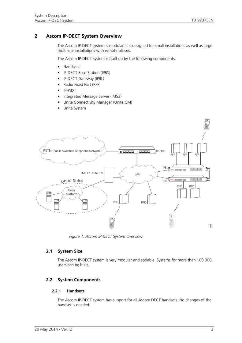
2 Ascom IP-DECT System Overview
The Ascom IP-DECT system is modular. It is designed for small installations as well as large multi-site installations with remote offices.
The Ascom IP-DECT system is built up by the following components:
• Handsets
• IP-DECT Base Station (IPBS)
• IP-DECT Gateway (IPBL)
• Radio Fixed Part (RFP)
• IP-PBX
• Integrated Message Server (IMS3)
• Unite Connectivity Manager (Unite CM)
• Unite System
LAN
PSTN (Public Switched Telephone Network)
Uniteplatform
Unite Suite
IMS3 / Unite CM
IPBS IPBS
RFP RFP
RFP RFP
RFP
IPBL
IPBL
001
IP-PBX
Figure 1. Ascom IP-DECT System Overview
2.1 System Size
The Ascom IP-DECT system is very modular and scalable. Systems for more than 100 000 users can be built.
2.2 System Components
2.2.1 Handsets
The Ascom IP-DECT system has support for all Ascom DECT handsets. No changes of the handset is needed.
20 May 2014 / Ver. O 3

TD 92375ENSystem DescriptionAscom IP-DECT System
2.2.2 IPBS
The IPBS has eight channels used for speech, message and alarm. The IPBS also has one channel which is reserved for messaging and alarm.
2.2.3 IPBL
Up to 16 RFPs can be connected to the IPBL. The IPBL has eight channels for each RFP used for speech, message and alarm. The IPBL also has two channels which are reserved for messaging and alarm. Totally the IPBL has 40 speech channels.
2.2.4 RFP
All Ascom TDM-DECT base stations can be connected to the IPBL.
2.2.5 IP-PBX
The Ascom IP-DECT system is connected to the IP-PBX with standardized H.323 or SIP protocol.
2.2.6 Integrated Message Server (IMS3)
The IMS3 contains support for messaging and alarm and connects the Ascom IP-DECT system to the Unite platform.
The IMS3 contains also a Device Manager which supports parameter and software download to handsets. For more information, see the Unite documentation.
All features are license dependent.
2.2.7 Unite Connectivity Manager (Unite CM)
The Unite CM contains support for messaging and alarm and connects the Ascom IP-DECT system to the Unite platform.
Depending on the version of the Unite CM it might also contains a Device Manager which supports parameter and software download to handsets. For more information, see the Unite documentation.
All features are license dependent.
The Ascom IP-DECT system is designed to enable voice traffic, messaging and alarm handling between handsets within an enterprise LAN. The Ascom IP-DECT system supports roaming and handover between all IPBSs and IPBLs in the system.
2.3 LAN and WAN
There are several vendors providing components needed to deploy a LAN/WAN. In order to achieve optimal performance for IP-DECT the following is recommended:
• Quality of Service (QoS)
• The infrastructure should be connected to a switched network. (i.e hubs or repeaters should be avoided)
• Depending on network size, a backbone of least 100 Mbps should be used.
20 May 2014 / Ver. O 4
TD 92375ENSystem DescriptionAscom IP-DECT System
2.4 Supported third-party functions
The Ascom developed products are designed to work in system provided by different vendors.
20 May 2014 / Ver. O 5

TD 92375ENSystem DescriptionAscom IP-DECT System
3 Ascom IP-DECT System
The Ascom IP-DECT system is connected via one or several IP-PBXs to the PSTN. For messaging purposes the Ascom IP-DECT system can be connected to one or several Integrated Message Servers (IMS3) or Unite Connectivity Managers (Unite CM), see 3.7 Messaging in Multiple Master Systems on page 23.
The Ascom IP-DECT system have a modular structure that can be modelled as a number of network entities. The network entities defined are:
• the entity offering the H323-DECT gateway functionality will be referred to as Radio• the entity acting as the proxy for the IP terminated DECT handsets within the coverage
of the associated Radios will be referred to as Master• the entity offering support for distribution of the DECT identity RFPI will be referred to
as Pari Master• the entity offering support for finding home location information will be referred to as
Mobility Master• the entity offering support for distribution of the CKI identity will be referred to as
Crypto Master
3.1 Software Components
An Multiple Master system consists of the following entities which are software components which can be activated in an IPBS and IPBL:
• Radio
• Master
• Pari Master
• Mobility Master
• Crypto Master
For information on how to set these software components, see Installation and Operation Manual for IP-DECT Base Station and IP-DECT Gateway.
3.1.1 Radio
The Radio is a software interface between DECT and H323.
Location registration requests that cannot be resolved locally are forwarded to the Master acting as Pari Master. If the handset cannot be resolved locally in the Pari Master, the Mobility Master needs to be involved in the process of resolving the home location master, as it has knowledge of all DECT handsets in the system. The RAS channel will be established by the Radio for the first handset assigned to a Master and maintained until the last handset assigned to this Master has left the Radio. Thus, the Radio may have several concurrent RAS channels established to different Masters. Information for authentication of the handset will be sent by the home location master to the Radio.
3.1.2 Master
This software component is responsible for the communication to the IP-PBX. Translation between the internal H.323 to the DECT Radios and the external protocol (H.323 / SIP) to the IP-PBX is done by this component.
A Master is responsible for the DECT handsets that are assigned to it. When the Master has been notified about that a handset is within coverage it makes a registration to the IP-PBX. This registration is maintained by the Master until a notification is received that the
20 May 2014 / Ver. O 6

TD 92375ENSystem DescriptionAscom IP-DECT System
handsets access rights has been terminated or the handset has detached. At startup the registration is done only for the handsets that notifies itself with the location registration message.
The Master will establish a RAS channel to any associated Mobility Master at startup. All DECT handsets in the HDB are sent to the Mobility Master, to be used in the home location master resolution process.
The Master is also responsible for the mapping of keypad information to supplementary PBX features. Some features are handled locally by the Master and some are communicated to the IP-PBX.
3.1.3 Pari Master
This software component is responsible for assigning RFPIs, being part of the same external handover domain, to the Radios associated. A Radio will always be given the same RFPI, based on the RFPI-mac-address association.
3.1.4 Mobility Master
The Mobility Master will establish a RAS channel to any associated Mobility Masters, for which roaming agreements has been configured. This ensures scalability to a world wide level by distributing the home location master information to local Radios and remote Mobility Masters in the system.
In an Enhanced DECT Security system, the Mobility Master will establish a RAS channel to the Crypto Master at startup. To guarantee that the assigned CKIs are system unique, all CKIs for the DECT handsets supporting Enhanced DECT Security are sent to the Crypto Master.
3.1.5 Crypto Master
This software component is responsible for assigning CKIs. The Crypto Master keeps track of all CKIs and allocates a new unique CKI whenever subscribing a new handset that supports Enhanced DECT Security in the system and frees values when unsubscribing. For more information about Enhanced DECT Security, see 3.2 Enhanced DECT Security.
3.2 Enhanced DECT Security
The enhanced DECT security feature is a mechanism to enhance DECT security by introduction of early encryption and re-keying during an ongoing call. It also addresses the security risk of staying permanently open for registration.
3.2.1 Early Encryption
This procedure is used for encryption of each DECT link, directly after establishment. The purpose is to protect data like caller ID and dialed digits, exchanged before encryption with the handsets private cipher key can start.
When a handset that supports early encryption is registered, a CKI with a corresponding DefCK is allocated/calculated and stored both in the handset and in the IP-DECT system. The CKI uniquely identifies the corresponding DefCK for each handset within the system. Later at each DECT link establishment this CKI is used to identify the DefCK to be used for early encryption of the link. The handset will release the connection in case early encryption activation is rejected.
20 May 2014 / Ver. O 7

TD 92375ENSystem DescriptionAscom IP-DECT System
3.2.2 Re-keying
This procedure periodically modifies the handsets private cipher key used for encryption of an ongoing call. The purpose is to protect against any attempts to crack the ciphering e.g. like super-computing.
3.2.3 Subscription Requirements
This procedure is used to control if registration is allowed or not. A system that permanently allows registration will make it possible for an attacker to do over-the-air subscriptions using exhaustive testing of AC-codes.
The subscription method “With System AC”, used to allow anonymous registrations, will permanently allow subscription attempts.Therefore, for safety reasons, when the anonymous registration is finished change the Subscription Method to "Disable"or "With User AC".
With the subscription method “With User AC”, the system will allow subscription attempts only after activation in the IPBS/IPBL web GUI. The system will thereafter remain in enabled subscription mode for a maximum time of two minutes. After successful registration of the activated IPEI, the system will not allow registrations any longer.
3.3 System Layout
This section describes examples of different system layout sizes:
• One Master systems, see 3.3.1 One Master Systems on page 9.
• Multiple Master systems, see 3.3.2 Multiple Master Systems on page 11.
• Multiple Mobility Master systems, see 3.3.3 Multiple Mobility Master Systems on page 16.
• One Master systems with Enhanced DECT Security, see 3.3.4 One Master Systems with Enhanced DECT Security on page 18.
• Multiple Master systems with Enhanced DECT Security, see 3.3.5 Multiple Master Systems with Enhanced DECT Security on page 19.
• Multiple Mobility Master systems with Enhanced DECT Security, see 3.3.6 Multiple Mobility Master Systems with Enhanced DECT Security on page 19.
20 May 2014 / Ver. O 8
TD 92375ENSystem DescriptionAscom IP-DECT System
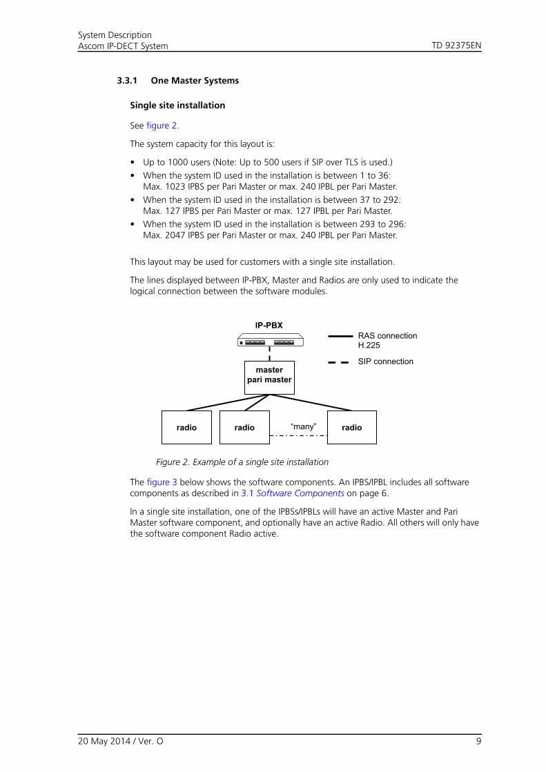
3.3.1 One Master Systems
Single site installation
See figure 2.
The system capacity for this layout is:
• Up to 1000 users (Note: Up to 500 users if SIP over TLS is used.)
• When the system ID used in the installation is between 1 to 36:Max. 1023 IPBS per Pari Master or max. 240 IPBL per Pari Master.
• When the system ID used in the installation is between 37 to 292:Max. 127 IPBS per Pari Master or max. 127 IPBL per Pari Master.
• When the system ID used in the installation is between 293 to 296:Max. 2047 IPBS per Pari Master or max. 240 IPBL per Pari Master.
This layout may be used for customers with a single site installation.
The lines displayed between IP-PBX, Master and Radios are only used to indicate the logical connection between the software modules.
“many”
masterpari master
radio radio radio
RAS connection H.225
SIP connection
IP-PBX
Figure 2. Example of a single site installation
The figure 3 below shows the software components. An IPBS/IPBL includes all software components as described in 3.1 Software Components on page 6.
In a single site installation, one of the IPBSs/IPBLs will have an active Master and Pari Master software component, and optionally have an active Radio. All others will only have the software component Radio active.
20 May 2014 / Ver. O 9

TD 92375ENSystem DescriptionAscom IP-DECT System
IP-PBX
masterpari mastermobility masterradio
masterpari mastermobility masterradio
masterpari mastermobility masterradio
masterpari mastermobility masterradio
Figure 3. Distribution of software components
Multiple site installation
See figure 4.
The system capacity for this layout is:
• Up to 1000 users (Note: Up to 500 users if SIP over TLS is used.)
• When the system ID used in the installation is between 1 to 36:Max. 1023 IPBS per Pari Master or max. 240 IPBL per Pari Master.
• When the system ID used in the installation is between 37 to 292:Max. 127 IPBS per Pari Master or max. 127 IPBL per Pari Master.
• When the system ID used in the installation is between 293 to 296:Max. 2047 IPBS per Pari Master or max. 240 IPBL per Pari Master.
This layout is chosen if there is no need for local functionality in remote sites.
The same layout as in a single site can also be used for customers with an installation on several sites. The sites may have one or several IPBS/IPBL at each site. The IP-PBX and the Pari Master and Master are centrally located.
With this solution the handset will be able to roam to a different site and it will be possible to receive incoming and make outgoing calls.
20 May 2014 / Ver. O 10

TD 92375ENSystem DescriptionAscom IP-DECT System
IP-PBX
radio
Central site
Remote site A Remote site B Remote site X
masterpari master
radio radio radio radio
Remote site A
radio radio
Remote site B
radio
Remote site X
radio
RAS connection H.225
SIP connection
IP-PBX
radio
CentralC site
masterpari master Radio coverage area
Figure 4. Multiple site installation
3.3.2 Multiple Master Systems
Single site installation
See figure 5.
The system capacity for this layout is:
• Up to 1000 users per Master (Note: Up to 500 users per Master if SIP over TLS is used.)
• When the system ID used in the installation is between 1 to 36:Max. 1023 IPBS per Pari Master or max. 240 IPBL per Pari Master.
• When the system ID used in the installation is between 37 to 292:Max. 127 IPBS per Pari Master or max. 127 IPBL per Pari Master.
• When the system ID used in the installation is between 293 to 296:Max. 2047 IPBS per Pari Master or max. 240 IPBL per Pari Master.
• Max. 100 Masters per Mobility Master
This layout may be used for customers with a large single site installation. Load must be distributed over a number of Masters to be able to cope with the load generated from a large number of handsets. It will be possible to do roaming and handover between all Radios.
The lines displayed between IP-PBX, Mobility Master, Master and Radios are only used to indicate the logical connection between the software modules.
20 May 2014 / Ver. O 11
TD 92375ENSystem DescriptionAscom IP-DECT System
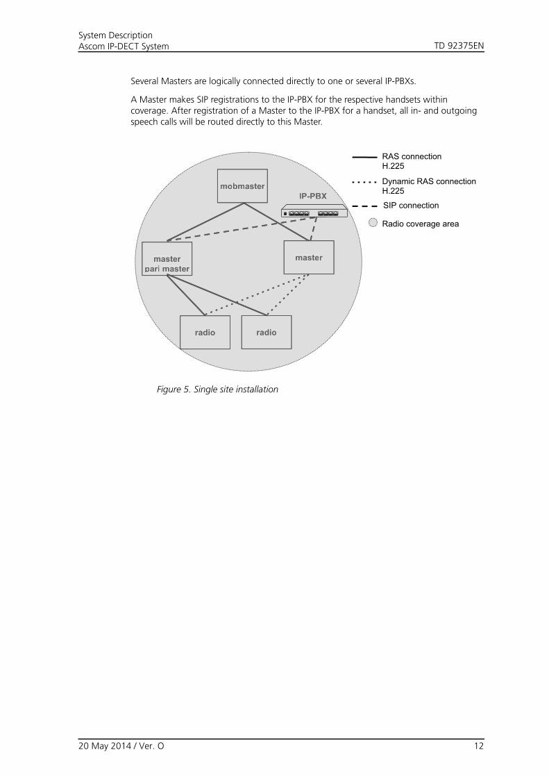
Several Masters are logically connected directly to one or several IP-PBXs.
A Master makes SIP registrations to the IP-PBX for the respective handsets within coverage. After registration of a Master to the IP-PBX for a handset, all in- and outgoing speech calls will be routed directly to this Master.
IP-PBX
masterpari master
radio
master
radio
mobmasterIP-PBX
masterpari master
radio
master
radio
mobmaster
RAS connection H.225
SIP connection
Radio coverage area
Dynamic RAS connection H.225
Figure 5. Single site installation
20 May 2014 / Ver. O 12
TD 92375ENSystem DescriptionAscom IP-DECT System
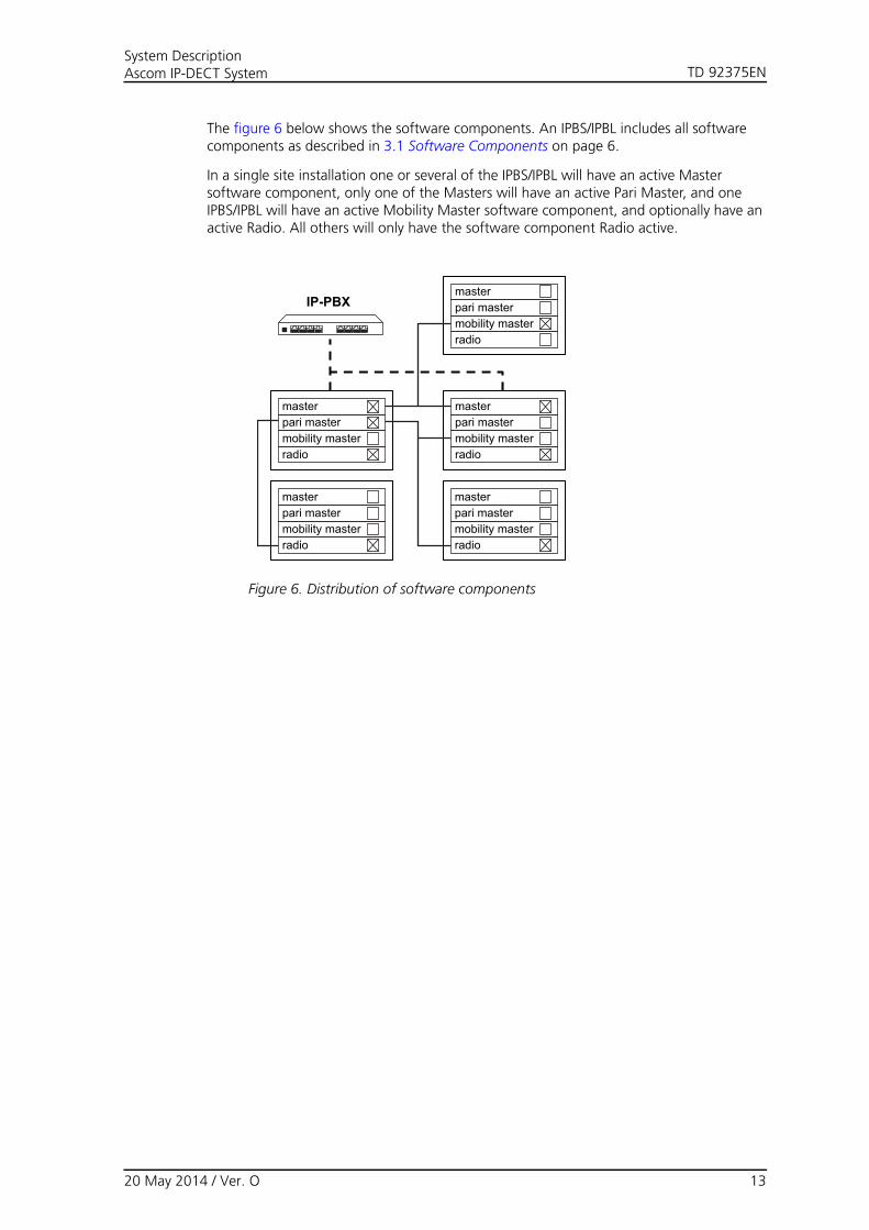
The figure 6 below shows the software components. An IPBS/IPBL includes all software components as described in 3.1 Software Components on page 6.
In a single site installation one or several of the IPBS/IPBL will have an active Master software component, only one of the Masters will have an active Pari Master, and one IPBS/IPBL will have an active Mobility Master software component, and optionally have an active Radio. All others will only have the software component Radio active.
IP-PBX
masterpari mastermobility masterradio
masterpari mastermobility masterradio
masterpari mastermobility masterradio
masterpari mastermobility masterradio
masterpari mastermobility masterradio
Figure 6. Distribution of software components
20 May 2014 / Ver. O 13

TD 92375ENSystem DescriptionAscom IP-DECT System
Multiple site installation
See figure 7.
The system capacity for this layout is:
• Up to 1000 users per Master (Note: Up to 500 users per Master if SIP over TLS is used.)
• When the system ID used in the installation is between 1 to 36:Max. 1023 IPBS per Pari Master or max. 240 IPBL per Pari Master
• When the system ID used in the installation is between 37 to 292:Max. 127 IPBS per Pari Master or max. 127 IPBL per Pari Master.
• When the system ID used in the installation is between 293 to 296:Max. 2047 IPBS per Pari Master or max. 240 IPBL per Pari Master.
• Max. 100 Masters per Mobility Master
This layout is chosen if there is no need for local functionality in remote sites.
The same layout as in a single site can also be used for customers with an installation on several sites. The sites may have one or several base stations at each site. The IP-PBX and the Pari Master and Master are centrally located.
With this solution the handsets will be able to roam to a different site and it will be possible to receive incoming and make outgoing calls.
Remote site B
IP-PBX
Central site
masterpari master
radioradio radio radio
Remote site B
radio
Remote site A
master
radio
mob master
radio radio
Remote site A
IP-PBX
Centrtt arr l site
masterpari master
radio
master
radio
mob master
RAS connection H.225
SIP connection
Radio coverage area
Dynamic RAS connection H.225
Figure 7. Multiple site installation with central Master
20 May 2014 / Ver. O 14

TD 92375ENSystem DescriptionAscom IP-DECT System
Multiple site installation with local functionality
See figure 8. The system capacity for this layout is:
• Up to 1000 users per Master (Note: Up to 500 users per Master if SIP over TLS is used.)
• When the system ID used in the installation is between 1 to 36:Max. 1023 IPBS per Pari Master or max. 240 IPBL per Pari Master.
• When the system ID used in the installation is between 37 to 292:Max. 127 IPBS per Pari Master or max. 127 IPBL per Pari Master.
• When the system ID used in the installation is between 293 to 296:Max. 2047 IPBS per Pari Master or max. 240 IPBL per Pari Master.
• Max. 100 Masters per Mobility Master
This layout is chosen if there is a need for local functionality in remote sites.
IP-PBX
Central site
masterpari master
radio radio radio
Remote site A
master
radio
mob master IP-PBX
Centrtt arr l site
masterpari master
radio
master
radio
mob master
masterpari master
radio radio
Remote site A
masterpari master
RAS connection H.225
SIP connection
Radio coverage area
Dynamic RAS connection H.225
Figure 8. Multiple site installation with remote Master
The figure 9 below shows the software components. An IPBS/IPBL includes all software components as described in 3.1 Software Components on page 6.
In site A, one of the IPBS/IPBL will have an active Master and Pari Master software component, and optionally have an active Radio. All others will only have the software component Radio active, see figure 8.
20 May 2014 / Ver. O 15

TD 92375ENSystem DescriptionAscom IP-DECT System
IP-PBX
masterpari mastermobility masterradio
masterpari mastermobility masterradio
masterpari mastermobility masterradio
masterpari mastermobility masterradio
Figure 9. Distribution of software components in remote site A.
3.3.3 Multiple Mobility Master Systems
See figure 10. The system capacity for this layout is:
• Up to 1000 users per Master (Note: Up to 500 users per Master if SIP over TLS is used.)
• Max. 10 Mobility Masters per System
• When the system ID used in the installation is between 1 to 36:Max. 1023 IPBS per Pari Master or max. 240 IPBL per Pari Master.
• When the system ID used in the installation is between 37 to 292:Max. 127 IPBS per Pari Master or max. 127 IPBL per Pari Master.
• When the system ID used in the installation is between 293 to 296:Max. 2047 IPBS per Pari Master or max. 240 IPBL per Pari Master.
• Max. 100 Masters per Mobility Master
This layout is chosen if there is a need for local functionality in a site with several Masters. This layout may be used for customers with large multiple site installations. Load must be distributed over a number of Masters to be able to cope with the load generated from a large number of handsets in one site. It will be possible to do roaming and handover between all Radios within each site. It will be possible to do roaming to all other sites to which roaming agreements exists and it will be possible to receive incoming and make outgoing calls.
The lines displayed between IP-PBX, Mobility Master, Master and Radios are only used to indicate the logical connection between the software modules.
A system can consist of several Masters where each Master is logically connected to a specific IP-PBX.
A Master dynamically makes SIP registrations to the “home” IP-PBX for each of the handsets within its coverage. After registration of a Master to the IP-PBX for a handset, all in- and outgoing speech calls will be routed directly to this Master.
20 May 2014 / Ver. O 16

TD 92375ENSystem DescriptionAscom IP-DECT System
IP-PBX IP-PBX
radio
masterpari master
radio
master
mob master
radio
masterpari master
radio
master
mob master
Site A Site B
IP-PBX
radio
masterpari master
radio
master
mob master
Site A
IP-PBX
radio
masterpari master
radio
master
mob master
Site B
RAS connection H.225
SIP connection
Radio coverage area
Dynamic RAS connection H.225
Figure 10. Multiple site installation
The figure 11 below shows the software components. An IPBS/IPBL includes all software components as described in 3.1 Software Components on page 6.
In each site one or several of the IPBS/IPBL will have an active Master software component, only one of the Masters will have an active Pari Master, and one IPBS/IPBL will have an active Mobility Master software component, and optionally have an active Radio. All others will only have the software component Radio active.
IP-PBX
masterpari mastermobility masterradio
masterpari mastermobility masterradio
masterpari mastermobility masterradio
masterpari mastermobility masterradio
masterpari mastermobility masterradio
Figure 11. Distribution of software components in site A and B.
20 May 2014 / Ver. O 17

TD 92375ENSystem DescriptionAscom IP-DECT System
3.3.4 One Master Systems with Enhanced DECT Security
“many”
masterpari master
radio radio radio
RAS connection H.225
SIP connection
IP-PBX
Note: The Crypto Master function needed for encryption, will be automatically activated in the Master.
Figure 12. Enhanced DECT Security in a one Master System
20 May 2014 / Ver. O 18
TD 92375ENSystem DescriptionAscom IP-DECT System
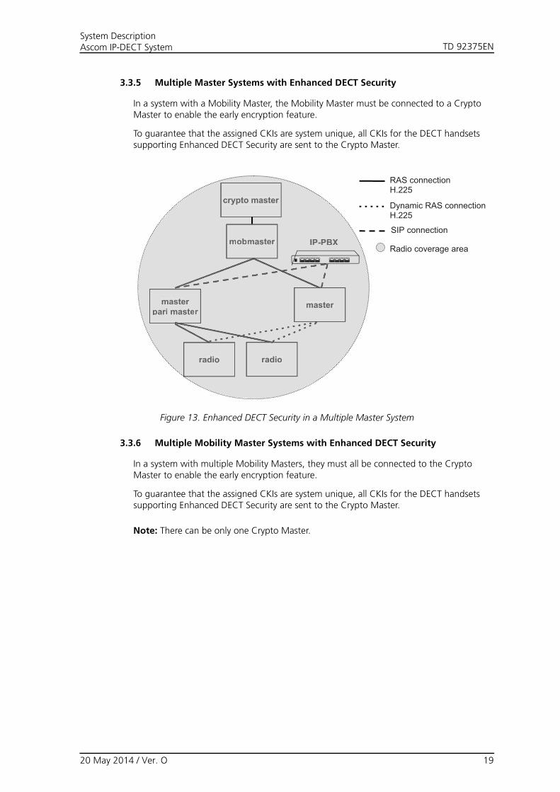
3.3.5 Multiple Master Systems with Enhanced DECT Security
In a system with a Mobility Master, the Mobility Master must be connected to a Crypto Master to enable the early encryption feature.
To guarantee that the assigned CKIs are system unique, all CKIs for the DECT handsets supporting Enhanced DECT Security are sent to the Crypto Master.
crypto master
IP-PBX
masterpari master
radio
master
radio
mobmaster
crypto master
IP-PBX
masterpari master
radio
master
radio
mobmaster
RAS connection H.225
SIP connection
Radio coverage area
Dynamic RAS connection H.225
Figure 13. Enhanced DECT Security in a Multiple Master System
3.3.6 Multiple Mobility Master Systems with Enhanced DECT Security
In a system with multiple Mobility Masters, they must all be connected to the Crypto Master to enable the early encryption feature.
To guarantee that the assigned CKIs are system unique, all CKIs for the DECT handsets supporting Enhanced DECT Security are sent to the Crypto Master.
Note: There can be only one Crypto Master.
20 May 2014 / Ver. O 19

TD 92375ENSystem DescriptionAscom IP-DECT System
IP-PBX IP-PBX
radio
masterpari master
radio
master
mob master
radio
masterpari master
radio
master
mob master
Site A Site B
IP-PBX
radio
masterpari master
radio
master
mob master
Site B
RAS connection H.225
SIP connection
Radio coverage area
Dynamic RAS connection H.225
cryptomaster
IP-PBX
radio
masterpari master
radio
master
mob master
Site A
cryptomaster
Figure 14. Enhanced DECT Security in a Multiple Mobility Master System
IP-PBX
masterpari mastermobility masterradio
masterpari mastermobility masterradio
masterpari mastermobility masterradio
masterpari mastermobility masterradio
masterpari mastermobility masterradiocrypto master
Figure 15. Distribution of software components in site A. Site B is the same but without Crypto Master.
20 May 2014 / Ver. O 20

TD 92375ENSystem DescriptionAscom IP-DECT System
3.4 Standby Devices
It is recommended to have Standby devices in an IP-DECT system. Depending on how the IP-DECT system is configured, standby devices can be Standby Master, Standby Pari Master, Standby Mobility Master. When a Master goes down the corresponding Standby Master takes over.
Read also about Mirror devices, see 3.5 Mirror Devices.
IP-PBX
radio radio
IP-PBX
radio radio
standby masterstandby pari master
masterpari master
Figure 16. An Ascom IP-DECT system with a Standby Pari Master.
3.5 Mirror Devices
For redundancy purposes, the Master can act in two ways: As Standby Master and Mirror. However, there are some limitations when using Standby Masters and in these cases using Mirror Masters can be a solution.
3.5.1 Description of Mirror Mode
Mirror Masters are configured in pairs in the same way as Active and Standby Masters are. A Mirror Master can act in both the two previous modes, Active and Standby. One Mirror will initially take the Active role while the other Mirror becomes the Standby. Both the previously used modes "Active" and "Standby" can now instead be set to "Mirror". It is not possible to mix the Mirror mode with any other modes, both masters must be set to Mirror.
The administrator decides which Mirror that initially should be the active one by clicking on the "Activate mirror" link in that device. When the active Mirror fails, the Mirror acting as the standby will automatically become the active Mirror. When the failing Mirror is in operation again it will take the role as the standby and stay inactive.
The administrator can, when both Mirrors are in operation, switch the active role by clicking on the "Switch active mirror" link. This should then be done within a maintenance window as all ongoing calls will be lost.
In the special case where both Mirrors become active due to a network error between the Mirrors, conflicts might arise when the connection between the Mirrors is established again. In this case the Mirror that became active most recently will "win" and changes made to the other mirror will be lost.
20 May 2014 / Ver. O 21

TD 92375ENSystem DescriptionAscom IP-DECT System
The LDAP replication of the user database between Mirrors will be done automatically when needed and no configuration of this is necessary when using the Mirror mode.
If LDAP replication is also used towards an IP6000 or an Active Directory this must be configured at both Mirrors. This replicator will be disabled automatically when the Mirror is inactive.
The Mirror mode will not affect the communication towards the IP-PBX except for the change of master IP address after a fail over.
3.5.2 Benefits With Mirror Mode Compared to Standby Mode
Note: For new installations we recommend to use the Mirror mode.
The functionality will not be limited when failing over to the Mirror that has acted as Standby. It will still be possible to add/edit/delete users, login/logout shared phones, and subscribe new handsets. With the Standby mode this is not possible.
When the failing Mirror becomes available again the system will not automatically fall back to this Mirror and this is not necessary from a functional point of view. If the administrator anyway wants this to happen it is possible to manually switch back to the previously active Mirror. This should then be done at an appropriate time as ongoing calls will be lost. With the Standby mode the fallback is uncontrolled and can be brutal as ongoing calls are lost.
The LDAP replication of users will be done automatically when needed and no configuration of this is necessary with the Mirror mode.
IP-PBX
radio radio
IP-PBX
radio radio
inactive mirror masterinactive mirror pari master
active mirror masteractive mirror pari master
Figure 17. An Ascom IP-DECT system with Mirror Masters.
3.6 Call Localization
When placing calls from IP-DECT in a multiple site installation, the IP-PBX has no way of knowing in which site the user is located because the call is always sent from that user's Master. Knowing the location becomes especially important for emergency calls.
In each Master it is possible to configure a region code which can consist of numbers 0-9, * and #. Each radio will be assigned the same region code as the PARI Master the radio is
20 May 2014 / Ver. O 22

TD 92375ENSystem DescriptionAscom IP-DECT System
connected to. When a call is placed, the Master responsible for that user will check if its region code is the same as the region code of the radio where the handset is located. If not, the region code of the radio will be added as a prefix to the dialed number.
Example (see the figure below): There are two sites (a PARI Master in each). Site A with region code *1# and site B with region code *2#.Case 1: A user, configured in the site A Master and located on a radio in site A, calls number 100, then number 100 is sent to the IP-PBX.Case 2: If the same user moves to site B and calls number 100, then the number *2#100 is sent to the IP-PBX (case 2).
IP-PBX
IP-PBX
masterpari master
radio radio radio
master(home location)
radio
mob master IP-PBX
masterpari master
radio
master(home location)
radio
mob master
masterpari master
IP-PBX
radio radio
masterpari master1
IP-PBX
masterpari master
radio radio radio
master(home location)
radio
mob master IP-PBX
masterpari master
radio
master(home location)
radio
mob master
masterpari master
radio radio
masterpari master
Site A
Regioncode *1#
Regioncode *2#
Site B
2
100 is sentto the IP-PBX
*2#100 is sent to the IP-PBX
Regioncode *1#
Regioncode *2#
Regioncode *1#
Regioncode *1#
Regioncode *1#
Regioncode *1#
Regioncode *2#
calls100
calls100
Site A Site B
Site A Site B
Case 1
Case 2
Figure 18. Call Localization using region codes.
3.7 Messaging in Multiple Master Systems
For messaging purposes the Ascom IP-DECT system can be connected to one or several Integrated Message Servers (IMS3) or Unite Connectivity Managers (Unite CM). To have
20 May 2014 / Ver. O 23

TD 92375ENSystem DescriptionAscom IP-DECT System
messaging functionality for all handsets in a multiple Master system, each Master with handsets assigned must have a connection to an IMS3 or Unite CM.
IP-PBX
radio
master
radio
mobmaster
masterpari master
IMS3 / Unite CM
Figure 19. Messaging in multiple Master systems.
20 May 2014 / Ver. O 24
TD 92375ENSystem DescriptionAscom IP-DECT System
3.8 Broadcast Messaging in Multiple Master Systems
With broadcast messaging it is possible to deliver one message to all users in the system simultaneously. When a message is sent as a broadcast all handsets in the coverage area can receive the message. Broadcast messaging is not 100% proof since the system does not get a delivery receipt from the handsets, but the message is sent three times to increase the reliability of the transmission.
Message with broadcast (e.g. fire alarm) must be sent via an IMS3 or Unite CM connected to the Pari Master since the Pari Master is the only Master that is always connected to all Radios. The message will then be transmitted to all Radios that are connected to the Pari Master. All handsets within the coverage area of the system, will receive the message.
3.9 Multicast Messaging in Multiple Master Systems
Multicast messaging makes it possible to create and reach large groups in the system. A multicast message is sent out simultaneously to all members in the group. All handsets in the coverage area can receive the message. Multicast messaging is not 100% proof since the system does not get a delivery receipt from the handsets, but the message is sent three times to increase the reliability of the transmission.
Multicast groups are configured in the Unite CM module. Message with multicast (e.g. fire alarm) must be sent via an IMS3 connected to the Pari Master since the Pari Master is the only Master that is always connected to all Radios. The message will then be transmitted to all Radios that are connected to the Pari Master.
Users that are members of multicast groups must be located/configured on the Pari Master. The users will only receive Multicast messages within its Pari Master domain.
3.10 Device Management
Note: The Unite CM support for the below functions is depending on the Unite CM software version.
A Device Manager (included in the IMS3/Unite CM) is an application for managing handsets and chargers in wireless systems. The Device Manager can be connected to one or several Masters. It is also possible to have several Device Managers in the Ascom IP-DECT system.
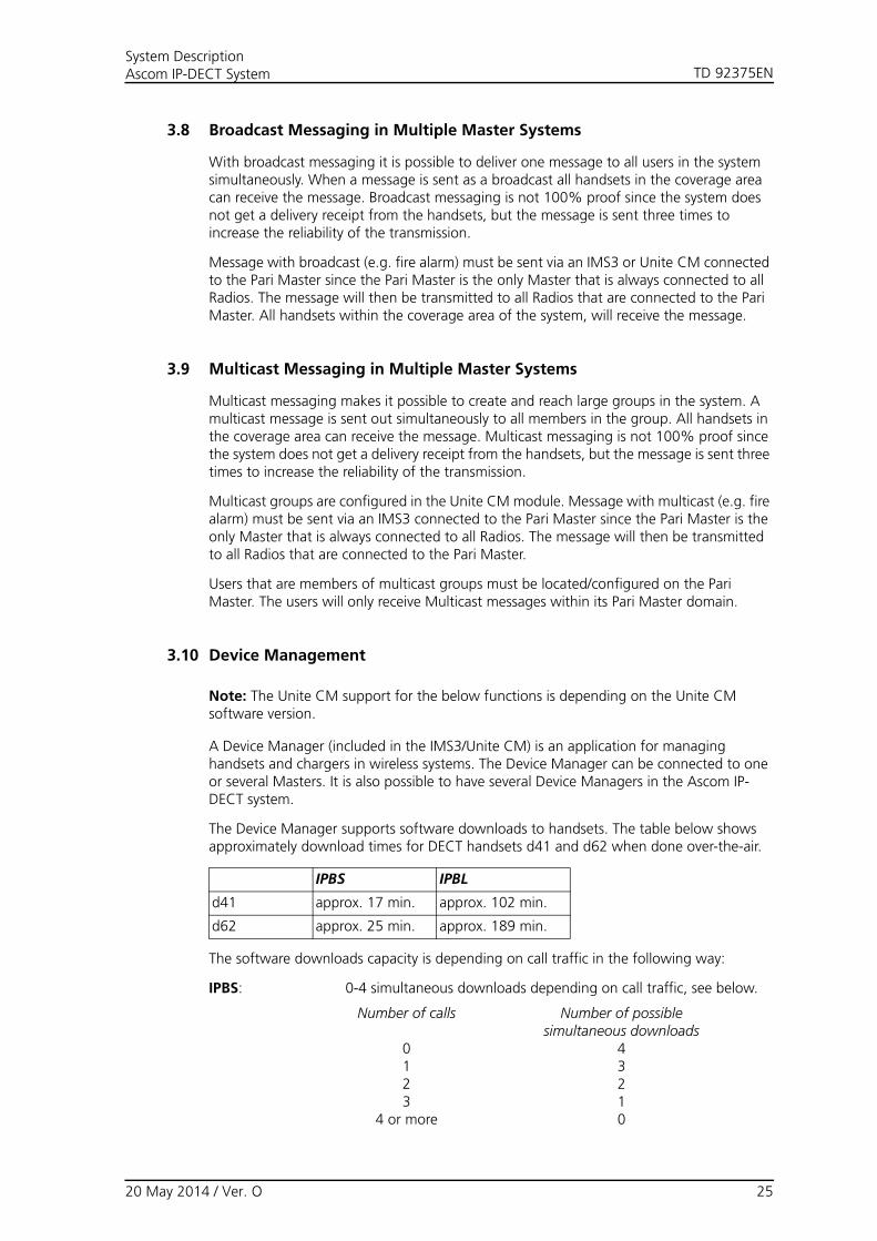
The Device Manager supports software downloads to handsets. The table below shows approximately download times for DECT handsets d41 and d62 when done over-the-air.
IPBS IPBL
d41 approx. 17 min. approx. 102 min.
d62 approx. 25 min. approx. 189 min.
The software downloads capacity is depending on call traffic in the following way:
IPBS: 0-4 simultaneous downloads depending on call traffic, see below.
Number of calls
0123
4 or more
Number of possiblesimultaneous downloads
43210
20 May 2014 / Ver. O 25

TD 92375ENSystem DescriptionAscom IP-DECT System
There are a number of factors that affect the software download time:
• The number of base stations.
• The number of handsets per base station.
• How much the handsets are moving between the base stations. When moving between RFPs there will be a 1-2 minute break in the software download.
• Speech calls will delay the software download.
3.11 Fault Reporting
Faults that occur in the Ascom IP-DECT system are shown locally in the faulty IPBS/IPBL. The faults can be forwarded to a central point (the Master) in the Ascom IP-DECT system. The faults can also be forwarded to the Ascom’s Messaging system and to an external SNMP manager.
3.12 Load Balancing
Load balancing can be used in an Ascom IP-DECT system when the number of handsets exceeds what an IP-PBX is able to register.
When load balancing, the traffic is distributed over several IP-PBXs which can be done in two ways using:
• fixed connections for users on each Master towards multiple IP-PBXs.
• dynamic connection for users on each Master towards IP-PBX network using DNS services.
For more information about load balancing, see Installation and Operation Manual for IP-DECT Base Station and IP-DECT Gateway.
IPBL: 0-4 simultaneous downloads depending on call traffic. Same limitations as for IPBS, see above.
IMS3/Unite CM: Max. 10 simultaneous downloads (max. 20 when using an external web server).
20 May 2014 / Ver. O 26

TD 92375ENSystem DescriptionAscom IP-DECT System
3.13 Synchronization
Synchronization within the Ascom IP-DECT system is done with the following methods:
• Air synchronization (IPBS)
• Ring synchronization (IPBL)
• Air and ring synchronization combined
3.13.1 Air Synchronization
If the planned system shall have IPBS base stations, both speech coverage and air sync coverage have to be considered. If the system only consists of TDM-DECT base stations, only speech coverage has to be considered.
Speech coverage: the radius of the circle (circular radiation patterns of the IPBS antennas are assumed for reasons of simplicity), around a particular IPBS, in which portable parts can communicate with that IPBS, see figure 20.
Sync coverage: the radius of the circle, around a particular IPBS, in which other IPBSs can synchronize with that IPBS with a given synchronization loss probability. This means that the size of the sync radius depends on requested probability of losing synchronization, see figure 20.
005
Air Sync Coverage
Speech Coverage
Figure 20. Air- and speech sync radius.
3.13.2 Ring Synchronization
Each synchronization port sends and receives synchronization signals. Each IPBL has two ports (in/out) for ring synchronization and two ports (in/out) for reference synchronization.
The ring synchronization can be made in two different ways:
• Redundant (preferred)
• Non redundant
Each synchronization ring dynamically assigns a sync master.
20 May 2014 / Ver. O 27

TD 92375ENSystem DescriptionAscom IP-DECT System
3.14 Channel Distribution
When a handset is used for speech, message, or alarm it always occupies one channel. However, when a handset is used for speech it can send or receive a message or an alarm on the same channel.
3.14.1 BS3x0 Connected to the IPBL
The BS3x0 that is connected to the IPBL has in total twelve channels. One channel is reserved for broadcast messages. Alarm from handset can occupy eleven channels. Messages to/from handsets can occupy ten channels but only eight speech calls can be handled simultaneous, see figure 21.
005
123456789101112
Speech
calls
Mess
ages
to/f
rom
handse
t
Ala
rm f
rom
handse
t
Bro
ad
cast
LAN
IPBL
Figure 21. Channel distribution in the BS3x0 connected to the IPBL.
This means that even if a BS3x0 reports that it is busy i.e. fully occupied with speech calls and/or messaging, there are always channels free for alarm from handset and broadcast messages.
3.14.2 IPBS
The IPBS has in total twelve channels. One channel is reserved for broadcast messages and two channels are reserved for synchronization. Alarm from handset can occupy nine channels but only eight speech and/or messaging can be handled simultaneously, see figure 22.
20 May 2014 / Ver. O 28

TD 92375ENSystem DescriptionAscom IP-DECT System
006
123456789101112
Speech
and M
ess
agin
g
Ala
rm f
rom
handse
t
Bro
ad
cast
LAN
Syn
c. b
eare
r
Figure 22. Channel distribution in the IPBS.
This means that even if a IPBS reports that it is busy i.e. fully occupied with speech calls and/or messaging, there are always channels free for alarm from handset and broadcast messages.
3.15 Ascom IP-DECT System Management
3.15.1 On Site Management
The IPBS and IPBL are is managed using a web GUI accessed over the LAN.
3.15.2 Remote Management
The IPBS and IPBL can be managed over the Internet using a VPN client.
Remote management is also possible by using the ESS module. For more information, see Function Description, Remote Management, TD 92257GB.
3.15.3 IP Administration Security
All IP administration is based on secure IP (HTTPS). All access to the IPBS and IPBL are password protected in order to prevent unauthorised access.
3.15.4 Software Upgrade
The IPBS and IPBL have support for software download and it is possible to do a software upgrade using the web interface. It also has support for automatic firmware update from a web server.
20 May 2014 / Ver. O 29

TD 92375ENSystem DescriptionAscom IP-DECT System
4 VoIP Signalling Protocols
Two of the protocols used for VoIP signalling are H.323 and SIP. H.323 was the first standard and is in fact a set of protocols designed to enable multimedia traffic in single LANs. One protocol of many in the set of protocols defined in H.323, is H.450, which is a series of protocols which defines Supplementary Services for H.323.
Like H.323, SIP can be used for VoIP but while H.323 is ISDN-based (Q. 931 and earlier H series), SIP is text-based. As opposed to H.323 which uses Abstract Syntax Notation number One (ASN.1), SIP encodes its messages as text, similar to HTTP and SMTP.
4.1 H.323
H.323 was developed by the International Telecommunications Union (ITU) and was designed from a telecommunications perspective. Ratified in 1996 it has become a defacto choice for interoperability among VoIP equipment. It is a standard that provides specification for computers, equipment, and services for multimedia communication over networks that do not provide a guaranteed QoS.
H.323 equipment can carry real-time video, audio, and data, or any combination of these elements. Included in the H.323 standard are H.225, H.245 and the IETF protocols RTP and RTCP, with additional protocols for call signalling, data and audiovisual communications.
H.323 products and services offer the following benefits to users:
• Products and services developed by multiple manufacturers under the H.323 standard can interoperate without platform limitations. H.323 conferencing clients, bridges, servers, and gateways support this interoperability.
• H.323 provides multiple audio and video codecs that format data according to the requirements of various networks, using different bit rates, delays, and quality options. Users can choose the codecs that best support their computer and network selections.
4.1.1 H.450 Supplementary Services for H.323
H.450 is a series of protocols which are used to exchange signalling information to control the supplementary services such as, Call Transfer, Call Diversion, Call Waiting etc. over a LAN.
4.2 Session Initiation Protocol (SIP)
SIP is an application layer control (signalling) protocol for creating, modifying, and terminating sessions with one or more participants. These sessions include Internet multimedia conferences, Internet telephone calls and multimedia distribution. SIP is designed as part of the IETF standards.
SIP itself is not sufficient to set up a call and other IETF protocols such as RTP and SDP are required to support a VoIP call. However, the functionality and operation of SIP does not depend on any of these protocols.
4.3 IP-DECT System Internal Communication
The internal communication is based on H.323 but is always encrypted.
The Mobility Master listens to the following port:
20 May 2014 / Ver. O 30
TD 92375ENSystem DescriptionAscom IP-DECT System
• 1718-1719 UDP
The Master listens to the following ports:
• 1718-1719 UDP
• 1716-1717 TCP
• 1722-1723 TCP
The Radio listens to the following ports:
• 1718-1719 UDP
• 1718-1719 TCP
• 1724-1727 TCP
The Radio may also listen to 1728 and upwards if in a Multiple Master system.
1718-1719 are used for connection with the PARI Master. 1724-1727 are used for DECT broadcast and multicast messaging. Two additional ports starting at 1728 will be used for each dynamic master connection. The dynamic connections are created and destroyed when users from other Masters than the PARI Master, enters and leaves the coverage area of the Radio.For example: In a system there are 4 Masters. One user from each Master is located on the same Radio. This Radio will then listen to ports 1718-1719,1724-1733.
5 Related Documents
System Planning, Ascom IP-DECT System TD 92422EN
Installation Guide, IP-DECT Base Station and IP-DECT Gateway TD 92989EN
Installation and Operation Manual for IP-DECT Base Station and IP-DECT Gateway
TD 92579EN
Data Sheet, IP-DECT Base Station TD 92370GB
Data Sheet, IP-DECT Base Station (IPBS2) TD 92836EN
Data Sheet, IP-DECT Gateway TD 92430GB
Installation and Operation Manual, Integrated Message Server (IMS3) TD 92762EN
Installation and Operation Manual, Alarm Management Server (AMS) TD 92047GB
Installation and Operation Manual, Enhanced System Service (ESS) TD 92253GB
Function Description, Remote Management TD 92257GB
Data sheet, Integrated Message server (IMS3) TD 92779EN
Data Sheet, Enhanced System Service (ESS) TD 92250GB
System Description, Unite TD 92243GB
20 May 2014 / Ver. O 31

TD 92375ENSystem DescriptionAscom IP-DECT System
Document History
For details in the latest version, see change bars in the document.
Version Date Description
A 2006-05-24 First released version.
B 2006-08-15 General improvments.
C 2007-01-15 New document structure.
D 2007-04-20 IP-DECT Gateway added.
E 2007-10-25 • Chapter 3.13.2 Ring Synchronization on page 27 updated.
• Appendix A Messaging Capacity updated.
F 2009-02-02 Major update of the document with the introduction of the Multiple Master system concept.
G 2009-04-15 Added some information about broadcast messaging and device management. Updated Appendix A: Messaging Capacity.
H 2010-03-05 Minor changes.
I 2010-09-24 Updated system capacity figures. Updated Appendix A Messaging Capacity. Added information about Multicast.
J 2010-10-22 Updated several figures etc.
K 2011-05-31 3.3.3 Multiple Mobility Master Systems on page 16 Updated to 10 Mobility Masters per system.
L 2011-06-29 Minor changes, see change bars.
M 31 May 20013 Updated1.1 Abbreviations on page 13.1.4 Mobility Master on page 73.3 System Layout on page 83.9 Multicast Messaging in Multiple Master Systems on page 25
New3 Ascom IP-DECT System on page 63.1.5 Crypto Master on page 73.2 Enhanced DECT Security on page 73.2.1 Early Encryption on page 73.2.2 Re-keying on page 83.2.3 Subscription Requirements on page 83.3.4 One Master Systems with Enhanced DECT Security on page 183.3.5 Multiple Master Systems with Enhanced DECT Security on page 193.3.6 Multiple Mobility Master Systems with Enhanced DECT Security on page 194.3 IP-DECT System Internal Communication on page 30
20 May 2014 / Ver. O 32

TD 92375ENSystem DescriptionAscom IP-DECT System
N 10 January 2014 Updated sections 3.3.1 One Master Systems on page 9, 3.3.2 Multiple Master Systems on page 11 and 3.3.3 Multiple Mobility Master Systems on page 16 to reflect that 2047 IPBSs can now be used per Pari Master in an installation by setting the system ID to 293-296.Updated sections 3.8 Broadcast Messaging in Multiple Master Systems on page 25 and 3.9 Multicast Messaging in Multiple Master Systems on page 25 regarding that broadcast and multicast messaging is not supported in large IP-DECT systems with more than 1023 IPBSs per Pari Master. (Issue IPDECT-509)
Have added section 3.5 Mirror Devices on page 21 to reflect that a new DECT Master mode "Mirror" has been added to the currently available modes. Both the previously used modes "Active" and "Standby" can now instead be set to "Mirror". (Issue IPDECT-355)
Have added section 3.6 Call Localization on page 22 which describes the new feature Call Localization. This feature is especially important for emergency calls when it is necessary to know the location of the calling party. (Issue IPDECT-633)
Have updated sections 3.8 Broadcast Messaging in Multiple Master Systems on page 25 and 3.9 Multicast Messaging in Multiple Master Systems on page 25 to explain the concept of broadcast and multicast messaging and that they are not 100% proof. (Issue IPDECT-644)
PO1 23 January 2014 Have updated sections 3.8 Broadcast Messaging in Multiple Master Systems on page 25 and 3.9 Multicast Messaging in Multiple Master Systems on page 25 regarding that broadcast and multicast messaging are now supported in large IP-DECT systems with more than 1023 IPBSs per Pari Master. Previously it was stated that broadcast and multicast messaging are not supported in large IP-DECT systems (Issue IPDECT-1193)
Have updated the section 4.3 IP-DECT System Internal Communication on page 30 with IP ports:1718-1719, 1722-1723, 1724-1727 and 1728. (Issue IPDECT-1191)
O 20 May 2014 Have only removed the preliminary stamp at top of pages.
Version Date Description
20 May 2014 / Ver. O 33

TD 92375ENSystem DescriptionAscom IP-DECT System
Appendix A. Messaging Capacity
A.1 Alarm Messages from DECT handset
A.2 No Highspeed Data to DECT handset 9d24
A.2.1 Incoming Messages to DECT handset 9d24 (version 3.0 or later)
The time for a message to be delivered differ dependent on how many characters the message contain and if it is delivered to a single handset or a group of handsets.
Number of message characters:No of DECT handsets:
For IPBL:Time in seconds until one handset is paged:
For IPBS:Time in seconds until one handset is paged:
20 characters 1 ~ 4 ~ 3
120 characters 1 ~ 5 ~ 3
240 characters 1 ~ 6 ~ 4
500 characters 1 ~ 9 ~ 7
Number of message characters:No of DECT handsets:
For IPBL:Time in seconds until all handsets are paged:
For IPBS:Time in seconds until all handsets are paged:
20 characters 11030100
~ 4~ 6~ 14~ 43
~ 3~ 4~ 11~ 32
120 characters 11030100
~ 5~ 7~ 17~ 56
~ 3~ 4~ 13~ 39
Time until received in the Unite system: ~ 2 sec
20 May 2014 / Ver. O 34
TD 92375ENSystem DescriptionAscom IP-DECT System
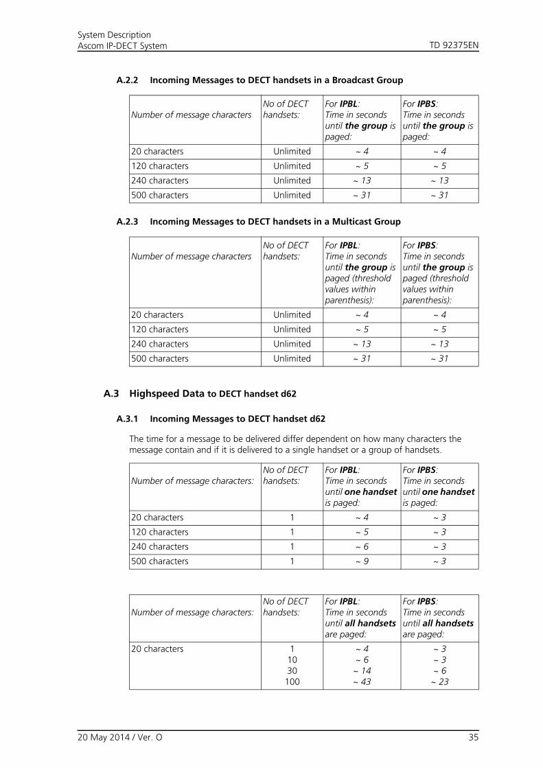
A.2.2 Incoming Messages to DECT handsets in a Broadcast Group
A.2.3 Incoming Messages to DECT handsets in a Multicast Group
A.3 Highspeed Data to DECT handset d62
A.3.1 Incoming Messages to DECT handset d62
The time for a message to be delivered differ dependent on how many characters the message contain and if it is delivered to a single handset or a group of handsets.
Number of message characters:No of DECT handsets:
For IPBL:Time in seconds until one handset is paged:
For IPBS:Time in seconds until one handset is paged:
20 characters 1 ~ 4 ~ 3
120 characters 1 ~ 5 ~ 3
240 characters 1 ~ 6 ~ 3
500 characters 1 ~ 9 ~ 3
Number of message charactersNo of DECT handsets:
For IPBL:Time in seconds until the group is paged:
For IPBS:Time in seconds until the group is paged:
20 characters Unlimited ~ 4 ~ 4
120 characters Unlimited ~ 5 ~ 5
240 characters Unlimited ~ 13 ~ 13
500 characters Unlimited ~ 31 ~ 31
Number of message charactersNo of DECT handsets:
For IPBL:Time in seconds until the group is paged (threshold values within parenthesis):
For IPBS:Time in seconds until the group is paged (threshold values within parenthesis):
20 characters Unlimited ~ 4 ~ 4
120 characters Unlimited ~ 5 ~ 5
240 characters Unlimited ~ 13 ~ 13
500 characters Unlimited ~ 31 ~ 31
Number of message characters:No of DECT handsets:
For IPBL:Time in seconds until all handsets are paged:
For IPBS:Time in seconds until all handsets are paged:
20 characters 11030100
~ 4~ 6~ 14~ 43
~ 3~ 3~ 6~ 23
20 May 2014 / Ver. O 35

TD 92375ENSystem DescriptionAscom IP-DECT System
A.3.2 Incoming Messages to DECT handsets in a Broadcast Group
A.3.3 Incoming Messages to DECT handsets in a Multicast Group
120 characters 11030100
~ 5~ 7~ 17~ 56
~ 3~ 3~ 9~ 27
Number of message charactersNo of DECT handsets:
For IPBL:Time in seconds until the group is paged:
For IPBS:Time in seconds until the group is paged:
20 characters Unlimited ~ 4 ~ 4
120 characters Unlimited ~ 5 ~ 5
240 characters Unlimited ~ 13 ~ 13
500 characters Unlimited ~ 31 ~ 31
Number of message charactersNo of DECT handsets:
For IPBL:Time in seconds until the group is paged (threshold values within parenthesis):
For IPBS:Time in seconds until the group is paged (threshold values within parenthesis):
20 characters Unlimited ~ 4 ~ 4
120 characters Unlimited ~ 5 ~ 5
240 characters Unlimited ~ 13 ~ 13
500 characters Unlimited ~ 31 ~ 31
20 May 2014 / Ver. O 36

TD 92375ENSystem DescriptionAscom IP-DECT System
Appendix B. Ascom Technical Documentation
This appendix explains the technical documentation structure and gives a description of each document type.
1. System Description (SD)
3. System Installation (SI)2. System Planning (SP)
User Manual (UM)
Installation Guide (IG)
Installation and Operation Manual (IOM)
Quick Reference Guide (QRG)
Data Sheet (DS)
System documents
Product documents
(Portable Devices only)
Function Description (FD)
(Software)(Fixed units)(Portable Devices,PC software)
(Describes functions on system- and product level, and requirementsto achive them.)
Repair Manuals (RM)1st, 2nd and 3rd line
Service documents
On-line Help (OH)
(Portable Devices, Fixed Units)
Configuration Manual (CM)(Settings for Products)
Configuration Notes (CN)(Settings for interconnection with other products)
Assembly Card (AC)(Products)
Figure 23. Document structure
System Description (SD)
Gives a general description of the system philosophy with basic functions and general configuration possibilities associated to functions.Target groups: is relevant for system responsible at the customer site, sales department, training department, project manager or whoever wants to know the basics of the system.
System Planning (SP)
Is to be read after taking part of the System Description. It describes different functions, possible technical system solutions and deals with factors that can affect the installation.Target groups: technical engineers planning a system.
20 May 2014 / Ver. O 37

TD 92375ENSystem DescriptionAscom IP-DECT System
System Installation (SI)
Primarily explains system dependent aspects to be considered at system installation and gives an overview of how to install the system.Target groups: technical engineers planning the system and technicians installing it
Function Description (FD)
Gives all relevant information, requirements and configuration notes, concerning functions in system and products, for example positioning, interactive messaging etc.Target groups: see under System Description section.
Configuration Manual (CM)
Describes the complete configuration for a specific product.Target groups: installation-, service-, support technicians and system responsible.
Configuration Notes (CN)
Describes configuration required for two or more interconnected products to achieve best performance or specific functions. Is a complement to other product specific documents.Target groups: installation-, service-, support technicians and system responsible.
Data Sheet (DS)
Technical data of a software/products etc. It includes a short list of features, applications and possibly extended functions with other software/products.Target groups: end customer, system responsible, technical engineers and sales department.
Installation Guide (IG)
Describes how to install any fixed units in the system.Target groups: installation- and service personnel.
Installation and Operation Manual (IOM)
Describes how to install and operate different PC software programmes. In many cases complemented with or replaced by on-line help or CD.Target groups: service engineer or administration responsible of the end user system.
Quick Reference Guide (QRG)
This document is available for handsets only. It contains a concise, how to use description, and is normally distributed together with the handset.Target groups: user of the handset for quick learning of included functions.
User Manual (UM)
For handsets:Is a complement to the QRG. It gives a thorough description of the specific functions and how to use the product for example a Transceiver.Target groups: responsible for handling the administration and distribution of pocket units at the end customer site, or anyone interested to get deeper usage knowledge.For PC Software:If it is preferable to separate installations and operations a UM describes how the end user operates the software.In many cases UM is complemented with on-line help.Target groups: End user.
On-Line Help (OH)
Gives help and information via the PC screen.
20 May 2014 / Ver. O 38

TD 92375ENSystem DescriptionAscom IP-DECT System
Repair Manual (RM)
For service and repair on some of the Ascom products. The document describes the repair of a product defined by one of three levels:1st Line RepairMechanical/cosmetic repair such as change of housing etc. and upgrade of software. No advanced soldering knowledge is needed but test equipment to verify functionality/quality after repair is needed. (Could also include test /programming equipment for field/onsite service).2nd Line RepairElectrical repair on PCB level, changing of PCB:s, minor electrical repair of PCB level and change of easily soldered parts. Test equipment to verify functionality/quality after repair is needed.3rd Line RepairAdvanced electrical repair on PCB level. Major knowledge in soldering technique is needed. Changing of SMD, BGA circuits etc. Advanced test equipment and equipment to verify functionality/quality after repair is needed.Target groups: service- and support technicians.
Assembly Card
Leaflet packed together with a product. Shows either how to mount or assembly some part, for example a battery back, or how to start up a product.
Old documents: II = Installation Instructions AA = Alignment and Adjustment SAG = Setup & Application GuideED = Electrical DiagramCD = Circuit DescriptionCL = Component Layout
20 May 2014 / Ver. O 39