system description electronic engine governor emr 2 manuals... · this system description provides...
TRANSCRIPT

System DescriptionElectronic Engine Governor EMR 2


© 06/02 Page 61
EMR 2Chapter Overview
1
2
3
4
5
6
7
8
9
10
11
12
13
Chapter
Introduction
Important Notes
System Description
System Functions
Interfaces
Configuration and Parameter Setting
Diagnostic Button and Fault Indicator Lamp
Replacement of System Components
Technical Data
Index of Specialist Terms
Index
Connection Diagams

Page 62 © 06/02
EMR 2Chapter Overview
1
2
3
4
5
6
7
8
9
10
11
12
12
© 06/02 Seite 63
EMR 2Table of Contents
Contents Page
1 Introduction 65
2 Important Notes 672.1 Operating instructions 672.2 Installation guidelines 672.3 Damage 672.4 Customer side wiring, plug connection 682.5 Remove plug 682.6 Electrical welding 68
3 System Description 693.1 Utilization of the EMR 2 693.2 System overview 693.3 Description of functions 703.4 Basic equipment 70
4 System Functions 714.1 Overview features 724.2 Function extensions 734.3 Speed control 744.4 Set point settings 764.5 Fuel quantity limitation (performance curve) 774.6 Droop control 784.7 Engine start/stop 784.8 Displays / Outputs (monitoring function) 794.9 LDA function 814.10 Temperature-dependent start control 814.11 Speed throttling (input F 7) 814.12 Engine protection functions 814.13 Altitude correction 824.14 Fuel volume control 824.15 Emergency running (limp home) 824.16 Cold start installation 82
5 Interfaces 835.1 Diagnostic interface (basic function) 835.2 CAN-Bus interface 83
6 Configuration and Parameter Setting 856.1 Function overview, pin assignment and configuration example 86
7 Diagnostic Button and Fault Indicator Lamp 877.1 Self-diagnostic (without operating the diagnostic button) 877.2 Diagnostic with Button and Error Code 907.3 Diagnostic possibilities with the SERDIA software 98
8 Replacement of system components 998.1 Replacement EMR ↔↔↔↔ EMR 2 998.2 Features of the Replacement of the Control Unit 998.3 Features of the Replacement of the Actuator 1008.4 Combination EMR, EMR 2, Control Unit and Actuator 100

Seite 64 © 06/02
EMR 2Table of Contents
9 Technical Data 1019.1 General Data 1019.2 Signal Specification 1029.3 Plug assignments 1039.4 Sensor Data 105
10 Index of Specialist Terms 107
11 Index 109
12 Connection diagrams 113
Appendix 11512.1 Connection diagram - Vehicle side / Unit side 11512.2 Connection diagram Engine side (sheet 1) 11612.3 Connection diagram Engine side (sheet 2) 11712.4 Connection diagram for CAN-Bus and Diagnostic Line 118

© 06/02 Page 65
1
2
3
4
5
6
7
8
9
10
11
12
13
EMR 2Introduction
1 Introduction
This system description provides an overview of the design and operation of the electronic engine governor(EMR 2) as a control unit when used in engines of the model series 1012/1013/2012/2013/10151).
In addition, an explanation is given of the functions of the EMR 2 and how problems with the EMR 2 can berecognized and overcome.
The EMR 2 is a further development of the previously utilized EMR.
Basically, it has the same functionality as the EMR, but is equipped with additional functions and extensi-ons that are summarized in Chapter 4.2.
Reference is made to Chapter 8 for information regarding replacements,
1) Same system with Bosch EDC-actuator (1015).
General notesIt is our aim to permanently improve and extend the contents of this brochure. For this purpose, the experi-ences of the circle of users can be particularly helpful.
Should you desire changes, extensions, improvements, etc., we would welcome your input (Engine mainte-nance technology department, VS-TI). Please make as much use of this as you wish. In this way, you areassisting in making the next version more up-to-date. We pay close attention to every message and willprepare a new issue of the brochure at the appropriate time. We thank you in advance for your cooperation.
Your
DEUTZ AG
Maintenance technology engines

1
2
3
4
5
6
7
8
9
10
11
12
12
Page 66 © 06/02
EMR 2Introduction

© 06/02 Seite 67
1
2
3
4
5
6
7
8
9
10
11
12
13
EMR 2Important Notes
2 Important Notes
2.1 Operating instructions
IMPORTANT!The purpose of this document is the explanation and clarification of the design and functionsof engines, engine components and systems.The information contained herein always corresponds to the technical conditions valid at thetime of going into print and are not subject to any immediate alteration service.
IMPORTANT!Applicable for the operation, maintenance and start-up are exclusively the information of thepublished and currently valid technical documentation, corresponding to the scope of deli-very and function (such as operating instructions, switching diagrams, workshop manual,repair and adjustment instructions, technical circulars, service information, etc.).
2.2 Installation guidelines
IMPORTANT!For the mechanical installation of the apparatus, reference should be made to the applicableissue of the “Installation Guidelines for electronic systems of DEUTZ diesel engines”. Moreinformation can be obtained from the DEUTZ AG, dept. technical operation support.
H REMARKS!Sufficient ventilation of control unit and actuator must be ensured in order to prevent limitati-ons of function and damage.
2.3 Damage
H REMARKS!Sensors and actuators may not be fitted individually to, or between, power sources for eitherinspection or testing purposes but only in connection with the EMR 2, as there is a danger ofdestruction!
H REMARKS!Despite polarity reversal protection in the control apparatus, it is necessary to prevent incor-rect polarity. Incorrect polarity can damage control units!
H REMARKS!The plug connections of the control units are only dust and watertight when plugged intomating connection! Until the mating connector has been plugged in, the control units must beprotected against spray water!

1
2
3
4
5
6
7
8
9
10
11
12
12
Seite 68 © 06/02
EMR 2Important Notes
2.4 Customer side wiring, plug connection
IMPORTANT!In order to attain the required protection class (IP 66) at the control unit, the individual wireseals, plugs and sealing rings provided must be used.
IMPORTANT!The connection between pins and individual wires must only be carried out with the properpinching tools.
H REMARKS!The voltage supply for inputs and outputs for the users must be able to be switched in a de-energized manner via the key switch (terminal 15) - not via continuous positive.
2.5 Remove plug
H REMARKS!Removing the 25-pole equipment plug and engine plug when the control unit is on, i.e. whenthe voltage supply is on (terminal 15 on) is not permitted.
1. Voltage supply off- only then -
2. pull out equipment plug and engine plug
2.6 Electrical welding
H REMARKS!In order to prevent damage when carrying out ELECTRIC welding of the installation, the plugconnections at the control unit must first be pulled out.
H REMARKS!The ignition (terminal 15) must be switched off when working at the EMR 2.

© 06/02 Page 69
1
2
3
4
5
6
7
8
9
10
11
12
13
EMR 2System Description
3 System Description
3.1 Utilization of the EMR 2
The purpose of the electronic engine governor (EMR 2) is the regulation of the speed of revolution of DEUTZDiesel engines of the model series 1012/1013/2012/2013/1015 for applications in agricultural and con-struction machinery as well as in generating sets. It is designed for heavy duty also under difficult environ-mental conditions and possesses the corresponding protection classes.
The governor fulfils all the functions of the mechanical governor (variable speed governing, torque limitati-ons, LDA function) and makes further functions available.
3.2 System overview
Basically, the EMR 2 consists of the sensors, the control unit and the actuator. Engine-side as well as vehicle-side or plant-side installation are connected by means of separate cable har-nesses to the EMR control unit. The cabling on the plant side is carried out by the vehicle or plant manufac-turer.
For arrangement on the engine and plant/vehicle side, see the following figure.
Charge-air pressure
sensor (optional) Power supply
Set and vehicle-side equipmentEngine-side equipment
Multi function displays
Outputs (modifiable)
Accelerator pedel
Hand operated throttle(optional)
Start/StopKey-operated switch
Functions changeoverswitch
Diagnostic button
Fault indicatorlamp
Diagnosis interface/CAN-Bus
Inputs (modifiable)(PWM/digital/analog)
2nd Speed sensor(optional)
Cold start aid(optional)
Fuel temperature(optional)
Charge air temperature(optional)Lifting solenoid
(optional)Oil pressure sensor
(optional)
Coolant temperaturesensor
Camshaft speedsensor
Control rod position sensor/
actuator -Control unit
Üs_en © 06/02*with atmospheric pressure sensor (otional)
1
2
3
4
5
6
7
8
9
10
11
12
12
Seite 70 © 06/02
EMR 2System Description
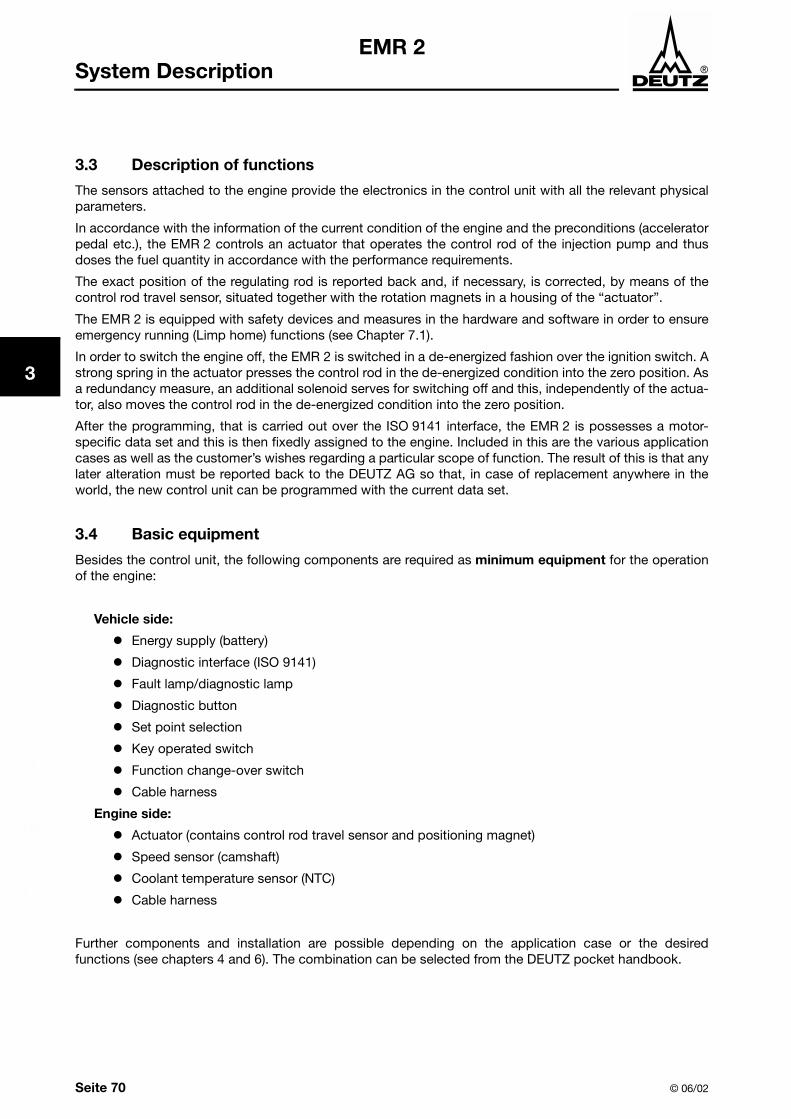
3.3 Description of functions
The sensors attached to the engine provide the electronics in the control unit with all the relevant physicalparameters.
In accordance with the information of the current condition of the engine and the preconditions (acceleratorpedal etc.), the EMR 2 controls an actuator that operates the control rod of the injection pump and thusdoses the fuel quantity in accordance with the performance requirements.
The exact position of the regulating rod is reported back and, if necessary, is corrected, by means of thecontrol rod travel sensor, situated together with the rotation magnets in a housing of the “actuator”.
The EMR 2 is equipped with safety devices and measures in the hardware and software in order to ensureemergency running (Limp home) functions (see Chapter 7.1).
In order to switch the engine off, the EMR 2 is switched in a de-energized fashion over the ignition switch. Astrong spring in the actuator presses the control rod in the de-energized condition into the zero position. Asa redundancy measure, an additional solenoid serves for switching off and this, independently of the actua-tor, also moves the control rod in the de-energized condition into the zero position.
After the programming, that is carried out over the ISO 9141 interface, the EMR 2 is possesses a motor-specific data set and this is then fixedly assigned to the engine. Included in this are the various applicationcases as well as the customer’s wishes regarding a particular scope of function. The result of this is that anylater alteration must be reported back to the DEUTZ AG so that, in case of replacement anywhere in theworld, the new control unit can be programmed with the current data set.
3.4 Basic equipment
Besides the control unit, the following components are required as minimum equipment for the operationof the engine:
Vehicle side:
! Energy supply (battery)
! Diagnostic interface (ISO 9141)
! Fault lamp/diagnostic lamp
! Diagnostic button
! Set point selection
! Key operated switch
! Function change-over switch
! Cable harness
Engine side:
! Actuator (contains control rod travel sensor and positioning magnet)
! Speed sensor (camshaft)
! Coolant temperature sensor (NTC)
! Cable harness
Further components and installation are possible depending on the application case or the desiredfunctions (see chapters 4 and 6). The combination can be selected from the DEUTZ pocket handbook.

© 06/02 Seite 71
1
2
3
4
5
6
7
8
9
10
11
12
13
EMR 2System Functions
4 System Functions
The EMR 2 makes a broad range of functions available and these can be activated by the application-dependent configuration and the allocation of the inputs and outputs. It makes possible signal exchangebetween the engine (via the engine plug) and the EMR 2, as well as between the vehicle (via the vehicleplug) and the EMR 2. The signals can be transmitted as analog, digital, impulse modulated (PWM signals)and as CAN-Bus messages.Which functions are used, depends on the application conditions of the engine. Correspondingly, there aredifferent variations of the functions and the pin assignments of the plugs.
The functions of the EMR 2 refer to the speed control, quantity limitations (fuel injection), monitoring,vehicle and apparatus functions and communication and diagnostic interfaces.
The EMR 2 offer a basic equipment on which all the optional variations can be structured.
Because of the numerous possibilities of combinations, DEUTZ has defined function ranges. These can becrossed off in the DEUTZ pocket handbook. The switching diagram for each function range should also benoted especially for the wiring required on the customers side.
Sensor inputs:
! Control rod travel! Speed! Coolant temperature! (Charge air pressure)! (Oil pressure)! (2nd speed)! (Coolant level)! (Charge air temperature)! (Fuel temperature)! (Tacho signal)
Actuator functions
! Actuator! (Switch-off magnet)
Display functions /outputs
! Fault lamp! (Warning signals)! (Multi-function dis-
plays)
Interfaces
! ISO 9141! CAN-Bus, SAE J1939
Microprocessor
Memory for
! Parameters! Char. curve ! Char. diagram! Faults
Set point input
! Key-operated switch! (Pedal sensor)! (Throttle lever)! (Via CAN-Bus)! (Voltage 0 - 5 V)! (PWM signal)
© 06/02
EMR 2(Atm pressure sensor)
Transfer switch forfunctions
The functions shown in brackets are optional.
Memory foroperatingsoftware
Energy supply

1
2
3
4
5
6
7
8
9
10
11
12
12
Seite 72 © 06/02
EMR 2System Functions
4.1 Overview features
Feature Chapter Description
Speed control 4.3
As variable speed, idling/end or fixed speed governor; choice of switchable governor features during operation, freezing the current speed, fixed speed governor for network synchronization or load distribution, overdrive speed
Set point input 4.4
By means of! Pedal sensor and/or hand throttle! External voltage signal (0 - 5 V)! CAN Bus (remote electronics)! Fixed speed signal (genset operation)! Pulse width modulation (PWM)! Touch control operation Up/Down (digital)Optimal adaptation to different applications
Torque limitation 4.5 Up to three performance curves can be set independently of each other within the framework of the engine limits
Governor behaviour (speed droop)
4.6 Constant, variable or switchable speed droop from 0 - 80 % for adaptation to the application
Engine Start/Stop 4.7 Engine switch-off by means of EMR actuator (additional safety using switch-off solenoid possible)
Monitoring and signaloutput functions
4.8
Coolant temperature and level, oil pressure, charge air temperature, fuel temperature → fault display and/or performance reduction or engine switch-off for engine protection
LDA function 4.9Smoke limitation through charge air pressure and/or temperature-dependent limitation of the adjustment speed of the injection
Temperature-dependent start control
4.10 Improving the starting ability, gentle cold start without smoke ejection
Altitude correction 4.13 Engine protection because of reduced air pressure
Fuel volume correction 4.14 Compensation for loss of performance due to fuel heating
Emergency running 4.15Emergency running after failure of set point signal (e.g. using accelerator pedal), the charge air sensor or the vehicle speed signal
Selection of coldstart help installations
4.16 Failure of auxiliary control units, EMR 2 controls a selection of heating flange, glow plugs or flame starting apparatus
Data communication 5 Interfaces, diagnostics and programming
Output of fault fault blink codes
7.2 Simplified fault diagnosis
© 06/02 Seite 73
1
2
3
4
5
6
7
8
9
10
11
12
13
EMR 2System Functions
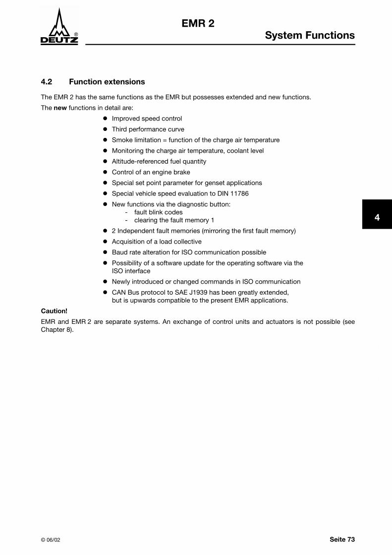
4.2 Function extensions
The EMR 2 has the same functions as the EMR but possesses extended and new functions.
The new functions in detail are:
! Improved speed control
! Third performance curve
! Smoke limitation = function of the charge air temperature
! Monitoring the charge air temperature, coolant level
! Altitude-referenced fuel quantity
! Control of an engine brake
! Special set point parameter for genset applications
! Special vehicle speed evaluation to DIN 11786
! New functions via the diagnostic button:- fault blink codes- clearing the fault memory 1
! 2 Independent fault memories (mirroring the first fault memory)
! Acquisition of a load collective
! Baud rate alteration for ISO communication possible
! Possibility of a software update for the operating software via the ISO interface
! Newly introduced or changed commands in ISO communication
! CAN Bus protocol to SAE J1939 has been greatly extended, but is upwards compatible to the present EMR applications.
Caution!
EMR and EMR 2 are separate systems. An exchange of control units and actuators is not possible (seeChapter 8).

1
2
3
4
5
6
7
8
9
10
11
12
12
Seite 74 © 06/02
EMR 2System Functions
4.3 Speed control
Provision is made for various variations of speed control that must be programmed in advance (at the endof the programming) depending on the application case (power generation, building or agricultural machi-nes) and usage conditions. The variations depend on the type of programmed and the selected functions.
The following types of speed regulation (switches) are optional and are programmed at the works depen-ding on the variant (pin assignment see Chapter 6.1):
Function Variant Description RemarksVariable speedcontrol
Variable speed
governor1)
1) Types of speed controlVariable speed control
For this type of control the speed of the engine is governed or kept constant with reference to the desired speed of revolution.For changes of load, the new required amount of fuel is set in accordance with a PID control. The desired value can bedetermined through various variants.
Min/Max controlFor this type of control, the fuel injection quantity is determined on the basis of the desired value. the result of this is that, forthis type of control, a speed of revolution depending on the load situation is set. The idling (= Minimum) and the endrevolutions (= Maximum) are controlled taking into account the control parameter speed droop 1 and speed droop 2. Thebasis for this type of control is the drive characteristic field.
Pure variable speed governor without addi-tion and switch-over functions
Only one vari-ant can be selectedFixed speed governor Variable speed governor with fixed, pre-defi-
ned speed for gensets (1,500 or 1,800 rpm), desired speed of rotation is defined in the scope of customer supply (KLU).
Change-over switching speed 1 /
22)
2) Change-over switching see point 4.3.1.
Variable speed governor with change-over switching possibility between two speeds.
Change-over swit-ching speed fixed/
variable2)
Variable speed governor with change-over switching possibility between a fixed pro-grammed and a variable speed of revolution.
Speed variable /
freeze2)Variable speed governor with change-over switching possibility between:freezing a current desired speed as set point independent of the pedal setting, and a varia-ble revolution.
Speed memoryfunction
Customer-specific solution for storing and calling up two speeds of revolution.
Gensetapplications
Power generationgovernor with adju-stable speed range
As for change-over switching fixed/variable speed. Without Load the speed can be adju-sted in the speed range.
See also system des-cription EMR Genset, TN 0297 9939
Power generation for network synchronisa-tion or Load distribu-tion
As for change-over switching fixed/variable speed. The variable revolutions can be adju-sted in the revolution range for network syn-chronization or load distribution.
Power generationgovernor with adju-stable speed and switchable overdrive speed
As for change-over switching fixed/variable speed the power generator, in fixed speed mode, can be used as the overdrive speed without loading, in variable mode or forparallel switching.
Variable speed-, Min/Max-control
Variable speed,
Min/Max governor2)Switching over between variable speed and Min/Max control.
Min/Max-control Min/Max governor1) Idling and end revolutions for vehicle applications.

© 06/02 Seite 75
1
2
3
4
5
6
7
8
9
10
11
12
13
EMR 2System Functions
4.3.1 Switchable speed functions
The conditions for the switchable variants are selected by means of a switch (Input pin 18, GND pin 17V plug). The switch closes a contact to -UBatt.
The following is applicable for the switchable speed functions:
The switching condition can be displayed with the aid of the SERDIA diagnostic software (see Chapter 7.3)
4.3.2 Second speed input (optional)
This input can be used as a redundant speed input. If a second speed sensor has been installed, then theengine will not be switched off on failure of the first speed sensor but will switch over to the second one.The failure of a speed sensor is indicated by the continuous burning of the fault lamp. The operation of theengine can be limited by defining a lower desired speed (see also Chapter 7.1).
4.3.3 Excess speed protection
when the speed limit is exceeded, the EMR 2 moves the control rod into the Stop position. The output,engine switch off (Digital 3, M 2) is activated (if it is programmed) and a fault message is generated.
With applications in mobile machines the thrust mode is programmed as a safety measure. Exceeding of the revolution limit can occur in thrust mode. In this case the control rod is moved to the zeroposition and the fault lamp lights up. The engine is protected against excess revolutions also in this type ofoperation.After falling below the programmed recovery limit, the governing is again taken up and the fault lamp isextinguished. The parameters “Above speed limit” and “Recovery limit” are adjustable.
Switchable speed functions(for a selectable)
Switch open1)
(1/HIGH)
1) With an open switch, the underlined conditions above are activated as preset values (default values).
Switch closed(0/LOW)
Speed 1/ speed 2 Speed 1 Speed 2
Fixed / variable speed Variable Fixed
Speed variable / freeze Variable Freeze
Variable speed governor / Min/Max governor
Variable speed governor Min/Max regulator

1
2
3
4
5
6
7
8
9
10
11
12
12
Seite 76 © 06/02
EMR 2System Functions
4.4 Set point settings
The following variants for the set point settings of the governor can be configured:
Function Variant Description Remarks
Set point setting Accelerator value sensor(SWG 1)
Setting with potentiometer (5 V reference
voltage, max. 30 mA1), typ. 1 kΩ linear, pin 25,
input pin 24, GND pin 23, V-plug2))
1) PIN 25: Imax=30 mA (Pedal value sensor and hand throttle combined).2) V*plug = Vehicle plug / GND = Ground.
Voltage Setting by means of external voltage (0.5 -4.5 V, input pin 24, GND pin 23, V-plug)
Replacement for pedal value sensor
Hand throttle(SWG 2)
Setting with hand throttle. The set point in the EMR 2 is determined by means of a maximum
function (5 V reference voltage, max. 30 mA1), typ. 1 kΩ linear, pin 25, input pin 20, GND pin 23 V-plug)
Memoryfunction
Freezing the current engine speed Only possible in con-nection with the pedal value sensor (SWG 1)
CAN Setting via the CAN interface (see Chapter 6.1)
CAN = Controller Area Network
Internal (fixed speed)
Setting via internal parameters. The parameter is determined in the customer scope of supply (KLU).
For gensets
PWM signal 1 PWM signal 2
The desired value is set by means of an exter-nal PWM signal (frequecyz=100 Hz) with a modulation of 5 % to 95 % (see Chapter. 9.2) Input pin 18 or 20, GND pin 17 V-plug
Auxiliary for pedal value sensor

© 06/02 Seite 77
1
2
3
4
5
6
7
8
9
10
11
12
13
EMR 2System Functions
4.5 Fuel quantity limitation (performance curve)
In order to set the engine performance and the desired torque course, the maximum injection quantity/thrust must be limited in accordance with the settings.
Provision is made in the EMR 2 for three performance curves. The performance curve is created as a cha-racteristic curve with 13 freely selectable speed support points. The sampling points must be supportpoints, whereby the sample of the engine is carried out with performance curve 1. The performance curve 2is correspondingly corrected with the correction data of performance curve 1.
Function Variant Description Remarks
Perfor-mance curve
Performance curve 1
Quantity limitation with a performance curve (perfor-mance curve 1)
Only 1 variant can be selected
Performance curves 1/2
Switching between two performance curves
Performance curves 1/2/3
Change-over switching only via CAN
Performance curve change-over switching (Input)
pin 19, GND pin17 V-plug
Switch open(1/HIGH)1)
1) With open switches, the underlined conditions above are activated as default values.
Switch closed(0/LOW)
Performance curve 1/ performance curve 2 Performance curve 1 Performance curve 2
1
2
3
4
5
6
7
8
9
10
11
12
12
Seite 78 © 06/02
EMR 2System Functions
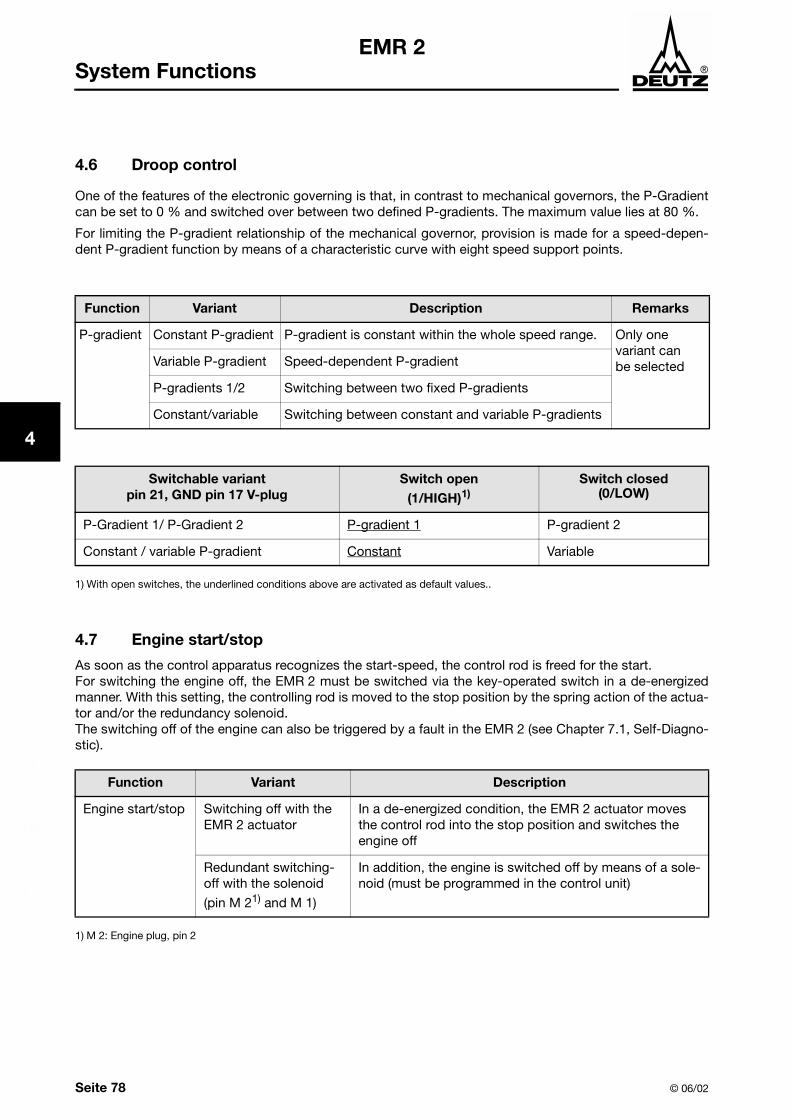
4.6 Droop control
One of the features of the electronic governing is that, in contrast to mechanical governors, the P-Gradientcan be set to 0 % and switched over between two defined P-gradients. The maximum value lies at 80 %.
For limiting the P-gradient relationship of the mechanical governor, provision is made for a speed-depen-dent P-gradient function by means of a characteristic curve with eight speed support points.
4.7 Engine start/stop
As soon as the control apparatus recognizes the start-speed, the control rod is freed for the start.For switching the engine off, the EMR 2 must be switched via the key-operated switch in a de-energizedmanner. With this setting, the controlling rod is moved to the stop position by the spring action of the actua-tor and/or the redundancy solenoid.The switching off of the engine can also be triggered by a fault in the EMR 2 (see Chapter 7.1, Self-Diagno-stic).
Function Variant Description Remarks
P-gradient Constant P-gradient P-gradient is constant within the whole speed range. Only one variant canbe selectedVariable P-gradient Speed-dependent P-gradient
P-gradients 1/2 Switching between two fixed P-gradients
Constant/variable Switching between constant and variable P-gradients
Switchable variantpin 21, GND pin 17 V-plug
Switch open(1/HIGH)1)
1) With open switches, the underlined conditions above are activated as default values..
Switch closed(0/LOW)
P-Gradient 1/ P-Gradient 2 P-gradient 1 P-gradient 2
Constant / variable P-gradient Constant Variable
Function Variant Description
Engine start/stop Switching off with the EMR 2 actuator
In a de-energized condition, the EMR 2 actuator moves the control rod into the stop position and switches the engine off
Redundant switching-off with the solenoid
(pin M 21) and M 1)
1) M 2: Engine plug, pin 2
In addition, the engine is switched off by means of a sole-noid (must be programmed in the control unit)

© 06/02 Seite 79
1
2
3
4
5
6
7
8
9
10
11
12
13
EMR 2System Functions
4.8 Displays / Outputs (monitoring function)
By means of the digital PWM outputs and depending on the configuration, various signals can be displayedand output.
Fault lamp (Pin 4 vehicle plug)
A red fault lamp must be placed where it is easily visible at the customer apparatus side. The fault lamp ser-ves as a rough estimate of the fault that has occurred; here the following means:
! Lamp 2 s on: Self diagnosis with switched on the voltage supply. Result: There are no faults.
! Continuous light: There is a fault message; however the system is operational (possibly limited).
! Flashing: Serious malfunction - engine will be switched off or engine cannot be started.
! Blink code: Query malfunction locality by means of diagnostic button.
For detailed information see Chapter 7.1.
Output signals (maximum of 4 output signals possible)
Function Variant Description
Display functions Speed 1(pin 16, vehicle plug)
Corresponding to the (No. of teeth on gear wheel) symmetrical square signal (Voltage level from 0 V to +UBatt)
Torque(pin 5, vehicle plug)
PWM signal (100 Hz) with button relationship from 5 to 95 %. Reference value: performance curve in the working point or MdMax
Warning signal coolant temperature(pin 3, vehicle plug)
Overstepping limiting valueHigh/Low change-over switching
Warning signal oil pres-sure(pin 15, vehicle plug)
Speed-dependent oil pressure controlHigh/Low change-over switching
Warning signal charge air monitor (pin variable)
General display for overstepping or falling below the limi-ting values
Freely selectable digital output signal
By arrangement
Freely selectable measu-ring or calculation value(PWM- signal)

1
2
3
4
5
6
7
8
9
10
11
12
12
Seite 80 © 06/02
EMR 2System Functions
Load collective
The EMR 2 measures the loading of the engine. For this purpose, the respective load and revolution regionsare allocated to the engine operating hours.
S1 to S9 are operating hours within the respective sector.
The load collective can only be displayed and printed with SERDIA.
© 06/02
Speed [rpm]
© 06/02
(torquemax)
Torque referred to torquemax [%]
100
50
30
S7 S8 S9
S4 S5 S6
S1 S2 S3
1000 2000 4000

© 06/02 Seite 81
1
2
3
4
5
6
7
8
9
10
11
12
13
EMR 2System Functions
4.9 LDA function
For mobile applications, the injection quantity for acceleration and dynamic load increase is limited withreference to the charge air pressure (smoke quantity-characteristic field). Usage: protection of the exhaustturbo supercharger and prevention of smoke ejection.
4.10 Temperature-dependent start control
In order to prevent smoke ejection and for optimizing the governing relationship, the start quantity, thespeed ramp and the governor parameters are controlled with reference to the temperature (required basicfunction).
4.11 Speed throttling (input F 7)
This function is designed for a driving speed evaluation is accordance with DIN 11786.
4.12 Engine protection functions
All monitoring functions can be provided with a message lamp on the plant side (dependent on the scope ofthe function and the pins that can be assigned).
Oil pressure monitoring
The user is warned by means of the message lamp when! the oil pressure has overstepped the warning limit and/or! after a pre-warning period, the performance has been reduced by the EMR 2, or! the oil pressure falls below the switch-off limit and, after a pre-warning period,
the engine is switched off.
Coolant temperature monitoring
The user is warned by means of the message lamp when! the temperature exceeds the warning limit and/or! after a pre-warning period, the performance has been reduced by the EMR 2, or! the temperature exceeds the switch-off limit and, after a pre-warning period,
the engine is switched off
Charge air monitoring
The user is warned by means of the message lamp when! the temperature exceeds the warning limit and/or! after a pre-warning period, the performance has been reduced by the EMR 2, or! The temperature exceeds the switch-off limit and after a pre-warning period, the engine is
switched off.

1
2
3
4
5
6
7
8
9
10
11
12
12
Seite 82 © 06/02
EMR 2System Functions
Coolant monitoring
The user is warned by means of the message lamp when! the coolant level falls below the warning limit and/or! after a pre-warning period, the performance has been reduced by the EMR 2, or! the the coolant level falls below the switch-off limit and, after a pre-warning period, the engine is
switched off.
4.13 Altitude correction
The altitude correction is carried out by means of an Atmospheric pressure sensor in the control unit. Twodifferent control unit variants are offered (with and without atmospheric pressure sensor).
4.14 Fuel volume control
Compensation for loss of performance due to fuel heating. Necessary variant with fuel temperature sensor.
4.15 Emergency running (limp home)
The EMR 2 provides comprehensive emergency running functions that are configured depending on thefield of application. These functions are necessary in order that, in an emergency, the operation can be con-tinued with auxiliary speed. In detail, this function can be activated by
a) set point defaultb) charge air pressurec) vehicle speed signal and/ord) speed acquisition
It is also possible by the failure of the set point default to switch over via CAN Bus
a) on the accelerator pedal andb) on auxiliary speed
The respective type of malfunction is defined in the fault memory.
4.16 Cold start installation
Failure of additional control units; if desired EMR 2 controls heating flange, glow plugs or flame start instal-lation.

© 06/02 Page 83
1
2
3
4
5
6
7
8
9
10
11
12
13
EMR 2Interfaces
5 Interfaces
The EMR 2 is equipped with various interfaces. The wiring is carried out on the customers side and must beintegrated in the vehicle plug. For pin assignment see the application-dependent switch diagrams.
5.1 Diagnostic interface (basic function)
The end programming of the EMR 2 is carried out via the serial diagnostic interface (according toISO 9141).
With the aid of a PC connected to an interface and the SERDIA (see also Chapter 7.3) diagnostic software -measuring values, error messages and other parameters can be displayed and set - depending on accessauthorization. Furthermore, new control units can be programmed.
Communication is only possible with the electric power switched on.
5.2 CAN-Bus interface
The CAN-Bus interface (Controller Area Network) is increasingly being used in vehicles and is suitable formeasuring values and data exchange with one or more apparatus-side control units (hydraulics, drive con-trol, etc.). The SAE J1939 protocol is utilized for communication.
The following is an aid to utilization of the respective scope of functions:
! Selection according to the DEUTZ pocket handbook! Definition before supply of engine! Connection in accordance with connection diagram (see Chapter 12.1 to 12.3)
Subsequent changes to the configuration is only possible in conjunction with the DEUTZ operating partnerand the aid of SERDIA (see Chapter 6).

1
2
3
4
5
6
7
8
9
10
11
12
12
Page 84 © 06/02
EMR 2Interfaces
© 06/02 Page 85
EMR 2 Configuration andParameter Setting
1
2
3
4
5
6
7
8
9
10
11
12
13
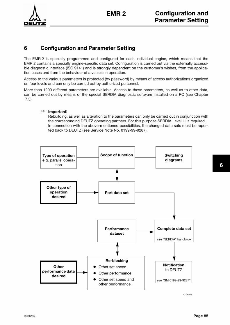
6 Configuration and Parameter Setting
The EMR 2 is specially programmed and configured for each individual engine, which means that theEMR 2 contains a specially engine-specific data set. Configuration is carried out via the externally accessi-ble diagnostic interface (ISO 9141) and is strongly dependent on the customer’s wishes, from the applica-tion cases and from the behaviour of a vehicle in operation.
Access to the various parameters is protected (by password) by means of access authorizations organizedon four levels and can only be carried out by authorized personnel.
More than 1200 different parameters are available. Access to these parameters, as well as to other data,can be carried out by means of the special SERDIA diagnostic software installed on a PC (see Chapter7.3).
Important!Rebuilding, as well as alteration to the parameters can only be carried out in conjunction withthe corresponding DEUTZ operating partners. For this purpose SERDIA Level III is required. In connection with the above-mentioned possibilities, the changed data sets must be repor-ted back to DEUTZ (see Service Note No. 0199-99-9287).
Type of operatione.g. parallel opera-
tion
Scope of function Switchingdiagrams
Other type ofoperationdesired
Part data set
Performance dataset
Complete data set
see “SERDIA” handbook
Notificationto DEUTZ
see “SM 0199-99-9287”
Re-blocking
! Other set speed
! Other performance
! Other set speed and other performance
Otherperformance data
desired
© 06/02

Page 86 © 06/02
EMR 2Configuration and Parameter Setting
1
2
3
4
5
6
7
8
9
10
11
12
12
6.1 Function overview, pin assignment and configuration example
Summarized function overview with examples of function selection
The user-referenced selection is carried out using the DEUTZ pocket handbook
Functions Plugengine/vehicle
Pin Input/OutputScope of function
(Example1))
1) Above example applicable to genset series 1012/1013, single frequency generating sets.
Scope of function 0211 2291Model No. 0029 3766No. of connection diagram engine side 0419 9752No.of connection diagram vehicle/plant side 0419 9780
Sensor inputsSpeed sensor 1 (camshaft) E 12, 13 E !
Speed sensor 2 (crankshaft) E 10, 11 E -Charge air sensor (LDA function) E 23, 24, 25 E -Oil pressure sensor E 20, 21, 22 E !
Atmospheric pressure sensor (in control unit) - - - -Coolant level sensor E 6, 8 E -Charge air temperature sensor E 4, 8 E -Fuel temperature sensor E 5, 8 E -Coolant temperature sensor E 9, 8 E -Control rod travel sensor E 16, 17, 18, 19 E !
Actuator functionsOperating solenoid E 14, 15 A -Dig. output (PWM) E 3 A -Solenoid E 2 A !
Default functions (set point defaults via)Hand throttle V 23, 20, 25 E -Voltage V 23, 24 E -Accelerator pedal (potentiometer) V 23, 24, 25 E !
CAN V 12, 13 E/A !
PWM signal 1 V 17, 18 E -PWM signal 2 V 17, 21 E -
Memory functionsFixed speed (upper limit) V 17, 18 E -Fixed speed (lower limit) V 17, 21 E -Freeze current speed V 17, 19 E -Limit fuel quantity of a performance curve !
Switch-over functionsspeed 1 / 2 V 17, 18 E -Fixed / variable speed V 17, 18 E -Freezing / variable speeds V 17, 18 E -Variable speed governor min/max regulation V 17, 18 E -Performance curve1 / 2 V 17, 19 E -Performance curve1 / 2 / 3 (via CAN) V 12, 13 E -P-gradient 1 / 2 V 17, 21 E !
P-gradient const. / variable V 17, 21 E -Key-operated Start/Stop, energy supply V 1, 14 !
Display / output functionsFault lamp V 4, (Cl. 15) A !
Warning coolant temperature V 3, (Cl. 15) A !
Warning oil pressure V 15, (Cl.15) A !
speed V 16, (Cl. 15) A -Torque (reserve) V 5, (Cl. 15) A -Warning monitoring charge air -Freely selectable digital output signal -Freely selectable measuring or calculation value -Load collective !
Diagnostic interfaceISO 9141-L V 10 E/A !
ISO 9141-K V 11 E/A !
CAN-Bus (SAE J1939 protocolCAN-H V 12 E/A !
CAN-L V 13 E/A !

© 06/02 Seite 87
EMR 2 Diagnostic Button andFault Indicator Lamp
1
2
3
4
5
6
7
8
9
10
11
12
13
7 Diagnostic Button and Fault Indicator Lamp
Diagnostic button and fault indicator lamp must be placed in the vehicle or plant on the customer side.They can be used for diagnosis.
7.1 Self-diagnostic (without operating the diagnostic button)
The EMR 2 possesses numerous protection functions for the engine - depending on the available measu-ring points or sensors. Depending on the seriousness of the recognized fault, the engine may run on inreduced mode (limp home), whereby the fault indicator lamp is continuously lit, or the engine is switchedoff, whereby the fault indicator lamp flashes.
A lit fault indicator lamp indicates an error in the wiring (short circuit, cable break) or a defect in the displaysof the corresponding sensors. A further source of faults could be falling below or exceeding the measuringvalue limits (see Chapter 9.4).
Faults in the electronics are registered or stored in the control unit and shown by the fault indicator lamp.The fault indicator lamp is extinguished as soon as the fault has been removed. Only when the electronicshas been switched to emergency running (-speed), need the engine be switched off briefly with the key-operated switch in order to extinguish the fault indicator lamp.
Also corrected or non-current faults remain stored in the control unit and can be read out or deleted withthe SERDIA diagnostic software (see Chapter 7.3).
+UBatt 15
Diagnostic button switch diagram
Pin F 4Fault indicator lamp
Diagnostic button
GND-UBatt
© 06/02

Seite 88 © 06/02
EMR 2Diagnostic Button and Fault Indicator Lamp
1
2
3
4
5
6
7
8
9
10
11
12
12
On
OffTime
2 s
On
OffTime
© 06/02
Key switch (terminal 15)
On
OffTime
On
OffTime
Fault indicator lamp
Case a) Lamp extinguished after 2 s: there is no active fault
2 s 1 s1 s
Case b) Lamp flashes after 2 s: there is at least one serious fault.the engine cannot be started.
Case c) Continuous light: there is at least one fault.
On
OffTime
2 s
Case d) As case c), only with monitoring delay tv dependent on selected setting.
tv

© 06/02 Seite 89
EMR 2 Diagnostic Button andFault Indicator Lamp
1
2
3
4
5
6
7
8
9
10
11
12
13
Function control of the configured warning lamps
With the activation of the key switch (pin 15), the warning lamp is also switched on for the duration of theself-diagnostic (2 s).
On
OffTime
2 s
On
OffTime
© 06/02
Key switch (terminal 15)
On
OffTime
Fault indicator lamp
2 s
e.g. warning lamp oil pressure
Seite 90 © 06/02
EMR 2Diagnostic Button and Fault Indicator Lamp
1
2
3
4
5
6
7
8
9
10
11
12
12
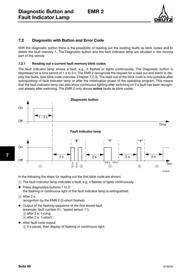
7.2 Diagnostic with Button and Error Code
With the diagnostic button there is the possibility of reading out the existing faults as blink codes and todelete the fault memory 1. The Diagnostic button and the fault indicator lamp are situated in the movingpart of the vehicle.
7.2.1 Reading out a current fault memory blink codes
The fault indicator lamp shows a fault, e.g., it flashes or lights continuously. The Diagnostic button isdepressed for a time period of 1 s to 3 s. The EMR 2 recognizes the request for a read out and starts to dis-play the faults. (see blink code overview, Chapter 7.2.3). The read-out of the blink code is only possible afterextinguishing of fault indicator lamp or after the initialization phase of the operating program. This meansthat the fault indicator lamp can also show continuous lighting after switching on if a fault has been recogni-zed already after switching. The EMR 2 only shows active faults as blink codes.
In the following the steps for reading out the first blink code are shown:
a The fault indicator lamp indicates a fault, e.g. it flashes of lights continuously.
! Press diagnostics buttons 1 to 3: the flashing or continuous light of the fault indicator lamp is extinguished.
b After 2 s: recognition by the EMR 2 (2×short flashes).
! Output of the flashing sequence of the first stored fault. (example: fault number 01, “speed sensor 1“):c after 2 s: 1×longd after 2 s: 1×short
! After fault code output e 5 s pause, then display of flashing or continuous light.
© 06/02
On
OffTime
1 - 3 s
Diagnostic button
Fault indicator lamp
On
OffTim
2 s 2 s 2 s
0.8 s 0.8 s
0.4
s
0.4
s
5 s
“2” “1” “1”
a b c d e

© 06/02 Seite 91
EMR 2 Diagnostic Button andFault Indicator Lamp
1
2
3
4
5
6
7
8
9
10
11
12
13
Steps for reading out the next fault:
a The fault indicator lamp indicates a fault, e.g. it flashes of lights continuously.
! Press diagnostics buttons 1 to 3:the flashing or continuous light of the fault indicator lamp is extinguished
b After 2 s: recognition by the EMR 2 (2×short flashes).
! The next blink code is output (c, d)
! After fault code output e 5 s pause, then display of flashing or continuous light.
The steps can be repeated until the last stored fault code is output. After that, the first fault code is shownagain.

Seite 92 © 06/02
EMR 2Diagnostic Button and Fault Indicator Lamp
1
2
3
4
5
6
7
8
9
10
11
12
12
7.2.2 Deletion of the fault memory 1
The EMR 2 has two fault memories (1 and 2). Every fault is stored in both memories at the same time. Withthe aid of the diagnostic button it is possible to delete passive faults in fault memory 1. The fault memory 2can only be deleted with SERDIA.
The following shows the steps for deleting the fault memory 1:
a Press, and keep depressed, the diagnostic button.
b Switch ignition on.
c Whilst the fault indicator lamp is lit up (duration 2 s) release diagnostic button.
d All passive faults in faults in fault memory 1 are deleted.
e The deletion process is confirmed by three short flash impulses.
© 06/02
On
OffTime
Diagnostic button
Fault indicator lamp
On
OffTime
0.4
s
0.4
s
On
OffTime
Key switch (terminal 15)
2 s
< 2 s
a
b
c
d e

© 06/02 Seite 93
EMR 2 Diagnostic Button andFault Indicator Lamp
1
2
3
4
5
6
7
8
9
10
11
12
13
7.2.
3F
ault
blin
k co
de
ove
rvie
w
Faul
t g
roup
Faul
t no
.(in
SE
RD
IA)
Fau
lt lo
calit
y/Fa
ult
des
crip
tio
nB
link
cod
eF
MI
SP
NC
ause
Rem
arks
Hel
p
sho
rtlo
ngsh
ort
0,4
s0,
8s
0,4
s
Zero
err
or
disp
lay
-N
o fa
ults
2-
-31
5242
87No
act
ive
faul
ts p
rese
nt
Revo
lutio
ns
/ spe
ed
acqu
isiti
on
01S
pee
d s
enso
r 1
21
18
190
Sens
or fa
ilure
. Dis
tanc
e fro
m g
ear
too
far.
Addi
tiona
l fau
lt im
puls
es.
Cabl
e jo
int i
nter
rupt
ed.
Gove
rnor
in e
mer
genc
y op
erat
ion
(if
sens
or 2
ava
ilabl
e). E
mer
genc
y sw
itch-
off (
if se
nsor
2 n
ot a
vaila
ble
or fa
iled)
. Ch
eck
dist
ance
. Che
ck c
able
co
nnec
tion.
Che
ck s
enso
r and
re
plac
e if
requ
ired.
02S
pee
d s
enso
r 2
21
28
190
Gove
rnor
in e
mer
genc
y op
erat
ion
(with
sen
sor 1
)Em
erge
ncy
switc
h-of
f (if
sens
or 1
no
t ava
ilabl
e or
faile
d).
03S
pee
d s
enso
r2
13
884
Tach
o fa
iled.
Add
ition
al fa
ult
impu
lses
. Cab
le c
onne
ctio
n in
terr
upte
d.Go
vern
or in
em
erge
ncy
oper
atio
n.
(see
Cha
pter
4.1
5).
Chec
k ca
ble
conn
ectio
n an
d Ta
cho.
Rep
lace
if re
quire
d.
04E
xces
s sp
eed
sw
itch-
off
21
40
190
Spee
d w
as/is
in e
xces
s of
lim
it.e.
Engi
ne s
top.
(s
ee C
hapt
er 4
.3.3
)Ch
eck
para
met
er(2
1). C
heck
sp
eed
setti
ngs.
Chec
k PI
D se
tting
. Che
ck ro
ds. C
heck
act
uato
r and
repl
ace
if re
quire
d. C
heck
cab
le to
act
uato
r (im
puls
e on
in
corr
ect s
peed
). Ch
eck
No. o
f tee
th. F
or v
ehic
les
chec
k fo
r pos
sibl
e th
rust
mod
e.
Sens
ors
05S
et p
oint
sen
sor
1ac
cele
rato
r p
edal
)2
21
291
Faul
t at c
orre
spon
ding
sen
sor e
ntry
(e
.g. s
hort
circ
uit o
r cab
le b
reak
).
See
Chap
ter 4
.15
influ
enci
ng fa
ult
reac
tion.
With
failu
re o
f the
sen
sor,
the
asso
ciat
ed m
onito
ring
func
tion
is
de-a
ctiv
ated
.
Chec
k se
nsor
cab
le. C
heck
se
nsor
and
repl
ace
if re
quire
d.
Chec
k fa
ult l
imits
for s
enso
r.
06S
et p
oint
sen
sor
2 (h
and
thr
ottle
)2
22
220
1
07C
harg
e ai
r p
ress
ure
22
32
102
08O
il p
ress
ure
22
42
100
09C
oola
nt t
emp
erat
ure
22
52
110
10C
harg
e ai
r te
mp
erat
ure
22
62
105
11Fu
el t
emp
erat
ure
22
72
174

Seite 94 © 06/02
EMR 2Diagnostic Button and Fault Indicator Lamp
1
2
3
4
5
6
7
8
9
10
11
12
12
Func
tiona
l fa
ult
war
ning
30O
il p
ress
ure
war
ning
23
11
100
Oil p
ress
ure
belo
w s
peed
-de
pend
ent w
arni
ng li
ne
char
acte
ristic
Faul
t mes
sage
(dis
appe
ars
whe
n oi
l pr
essu
re is
aga
in a
bove
reco
very
lim
it).
Afte
r a d
elay
tim
e - f
ill li
mita
tion.
Chec
k en
gine
(oil
leve
l, oi
l pu
mp)
. Che
ck o
il pr
essu
re
sens
or a
nd c
able
. Che
ck o
il pr
essu
re w
arni
ng li
ne
char
acte
ristic
.
31C
oola
nt t
emp
erat
ure
war
ning
23
20
110
Cool
ant t
empe
ratu
re h
as e
xcee
ded
war
ning
leve
l.
Faul
t mes
sage
(dis
appe
ars
whe
n co
olan
t tem
pera
ture
aga
in d
rops
be
low
reco
very
leve
l). A
fter a
del
ay
time
- fill
lim
itatio
n.
Chec
k co
olan
t. Ch
eck
cool
ant
tem
pera
ture
sen
sor a
nd c
able
.
32C
harg
e ai
r te
mp
erat
ure
war
ning
23
30
105
Char
ge a
ir te
mpe
ratu
re h
as
exce
eded
war
ning
leve
l.
Faul
t mes
sage
(dis
appe
ars
whe
n ch
arge
air
tem
pera
ture
gai
n dr
ops
belo
w re
cove
ry le
vel).
Afte
r a d
elay
tim
e - f
ill li
mita
tion.
Chec
k ch
arge
air.
Che
ck c
harg
e ai
r-te
mpe
ratu
re s
enso
r and
ca
ble.
34C
oola
nt le
vel w
arni
ng2
35
111
1Sw
itch
inpu
t “Lo
w c
oola
nt le
vel”
is
activ
e.Fa
ult m
essa
ge.
Chec
k co
olan
t lev
el. C
heck
co
olan
t lev
el s
enso
r and
cab
le.
35S
pee
d w
arni
ng (w
ith
thru
st m
ode
oper
atio
n).
23
614
SID
190
revo
lutio
ns w
as/is
abo
ve (t
op)
revo
lutio
n sp
eed
limit.
“Th
rust
m
ode”
func
tion
is a
ctiv
e.Se
e Ch
apte
r 4.3
.3 E
xces
s sp
eed
prot
ectio
n.Ch
eck
para
met
ers.
Che
ck s
peed
se
tting
s(21
).
Chec
k PI
D se
tting
. Che
ck ro
ds. C
heck
act
uato
r and
repl
ace
if re
quire
d. C
heck
cab
le to
act
uato
r. Ch
eck
spee
d se
nsor
(im
puls
es o
n in
corr
ect s
peed
). Ch
eck
No. o
f tee
th. F
or v
ehic
les
chec
k fo
r pos
sibl
e th
rust
mod
e.
36Fu
el t
emp
erat
ure
war
ning
23
70
174
Fuel
-tem
pera
ture
has
exc
eede
d w
arni
ng le
vel.
Faul
t mes
sage
(dis
appe
ars
whe
n fu
el
tem
pera
ture
aga
in d
rops
bel
ow
reco
very
leve
l).
Chec
k fu
el. C
heck
fuel
te
mpe
ratu
re s
enso
r and
cab
le.
Faul
t g
roup
Faul
t no
.(in
SE
RD
IA)
Fau
lt lo
calit
y/Fa
ult
des
crip
tio
nB
link
cod
eF
MI
SP
NC
ause
Rem
arks
Hel
p
sho
rtlo
ngsh
ort
0,4
s0,
8s
0,4
s

© 06/02 Seite 95
EMR 2 Diagnostic Button andFault Indicator Lamp
1
2
3
4
5
6
7
8
9
10
11
12
13
Func
tiona
l fa
ult,
switc
h-of
f
40O
il p
ress
ure
switc
h-of
f2
31
110
0Oi
l pre
ssur
e be
low
sw
itch-
off l
imit
Emer
genc
y st
op
Chec
k en
gine
(oil
leve
l, oi
l pu
mp)
. Che
ck o
il pr
essu
re
sens
or a
nd c
able
. Che
ck o
il pr
essu
re -s
witc
h-of
f lim
it.
41C
oola
nt t
emp
erat
ure
switc
h-of
f2
32
011
0Co
olan
t tem
pera
ture
has
exc
eede
d sw
itch-
off l
imit.
Chec
k co
olan
t lev
el. C
heck
co
olan
t lev
el s
enso
r and
cab
le.
Chec
k sw
itch-
off l
imit.
42C
harg
e ai
r te
mp
erat
ure
switc
h-
off
23
30
105
Char
ge a
ir te
mpe
ratu
re h
as
exce
eded
sw
itch-
off l
imit.
Chec
k ch
arge
air.
Che
ck c
harg
e ai
r-te
mpe
ratu
re s
enso
r and
ca
ble.
Che
ck s
witc
h-of
f lim
it.
44C
oola
nt le
vel s
witc
h-of
f2
35
111
1Sw
itch
inpu
t “Lo
w c
oola
nt le
vel”
is
activ
e.Em
erge
ncy
stop
. Sta
rt lo
ck.
Chec
k co
olan
t lev
el. C
heck
co
olan
t lev
el s
enso
r and
cab
le.
Actu
ator
50Fe
edb
ack
25
1
12S
ID 2
4
Actu
ator
not
con
nect
ed. F
ault
in
actu
ator
con
firm
atio
n.Em
erge
ncy
switc
h-of
f. Ac
tuat
or
cann
ot b
e op
erat
ed.
Chec
k ac
tuat
or, r
epla
ce if
re
quire
d. C
heck
cab
le, c
heck
fa
ult l
imits
for “
Conf
irmat
ion”
.
52R
efer
ence
feed
bac
k13
SID
24
Chec
k ac
tuat
or, r
epla
ce if
re
quire
d. C
heck
cab
le, c
heck
fa
ult l
imits
for “
Rife
ness
co
nfirm
atio
n”.
53C
ontr
ol t
rave
l d
iffer
ence
7S
ID 2
3In
ject
ion
pum
p/ac
tuat
or ja
mm
ed o
r no
t con
nect
ed. D
iffer
ence
bet
wee
n no
min
al/a
ctua
l con
trol t
rave
l is
>10
% o
f the
ove
rall
cont
rol p
ath.
Faul
t mes
sage
(dis
appe
ars
whe
n di
ffere
nce
is <
10%
).Ch
eck
actu
ator
/act
uato
r rod
s /
inje
ctio
n pu
mp,
repl
ace
if re
quire
d. C
heck
act
uato
r cab
le.
59A
uto
calib
ratio
n B
OS
CH
-ED
C p
ump
s fa
ulty
op
erat
ion
25
213
SID
23
No a
utom
atic
act
uato
r equ
aliza
tion
poss
ible
. Inc
orre
ct in
put o
f the
ac
tuat
or re
fere
nce
valu
es.
Engi
ne s
top
/ sta
rt lo
ck. G
over
nor
cann
ot b
e ta
ken
into
use
. EDC
ac
tuat
or c
alib
ratio
n re
quire
d(s
ee C
hapt
er8.
4).
Chec
k ac
tuat
or a
nd re
plac
ed if
re
quire
d. C
heck
feed
back
cab
le.
Chec
k vo
ltage
sup
ply/
cabl
es.
Chec
k fa
ult l
imits
and
refe
renc
e va
lues
of t
he fe
edba
ck. P
rogr
am
the
faul
t lim
its fo
r fee
dbac
k, s
ave
valu
es. S
witc
h ig
nitio
n of
f and
on
agai
n.Ch
eck
agai
n. If
faul
ty,
info
rm D
EUTZ
-Ser
vice
and
car
ry
out a
utom
atic
equ
aliza
tion
agai
n.
Set f
ault
limits
aga
in.
Faul
t g
roup
Faul
t no
.(in
SE
RD
IA)
Fau
lt lo
calit
y/Fa
ult
des
crip
tio
nB
link
cod
eF
MI
SP
NC
ause
Rem
arks
Hel
p
sho
rtlo
ngsh
ort
0,4
s0,
8s
0,4
s

Seite 96 © 06/02
EMR 2Diagnostic Button and Fault Indicator Lamp
1
2
3
4
5
6
7
8
9
10
11
12
12
Hard
war
e in
puts
/ou
tput
s
60D
igita
l out
put
3
(Sw
itch-
off s
olen
oid
, p
in M
2)2
61
2S
ID 5
1Fa
ult (
shor
t circ
uit /
cab
le b
reak
) at
digi
tal o
utpu
t.
Driv
er le
vel i
s sw
itche
d of
f.Ch
eck
cabl
e of
dig
ital o
utpu
t (c
able
bre
ak o
r sho
rt ci
rcui
t).
62D
igita
l out
put
6, p
in
M7
26
22
SID
60
Faul
t mes
sage
.
63E
xces
s vo
ltage
sw
itch-
off s
olen
oid
26
16
SID
51
67E
rror
Han
d S
etp
12
62
1191
68E
rror
CA
N S
etp
12
898
Com
mun
i-ca
tion
70C
AN
-Bus
con
trol
ler
27
1
12S
ID 2
31CA
N-co
ntro
ller f
or C
AN-b
us is
fa
ulty
. Fau
lt re
mov
al d
espi
te re
-in
itial
isin
g co
ntin
uous
ly n
ot
poss
ible
Ap
plic
atio
n-de
pend
ent.
Chec
k CA
N co
nnec
tion,
te
rmin
atin
g re
sist
or (s
ee C
hapt
er
12.4
), Ch
eck
cont
rol u
nit.
71C
AN
inte
rfac
e S
AE
J19
399
SID
231
Over
flow
in in
put b
uffe
r or a
tra
nsm
issi
on c
anno
t be
plac
ed o
n th
e bu
s.
74C
able
bre
ak,
shor
t ci
rcui
t or
b
us-e
rror
14S
ID 2
31Ch
eck
CAN
conn
ectio
n, c
able
co
nnec
tion.
Che
ck s
enso
r and
re
plac
e if
requ
ired.
Mem
ory
76P
aram
eter
p
rogr
amm
ing
(writ
e E
EP
RO
M)
28
1
12S
ID 2
53Fa
ult i
n pa
ram
eter
pro
gram
min
g in
th
e go
vern
or fi
xed
valu
e m
emor
y.
Emer
genc
y sw
itch-
off.
engi
ne c
anno
t be
sta
rted.
Switc
h ig
nitio
n of
f and
on
agai
n.
Chec
k ag
ain.
If fa
ulty
info
rm
DEUT
Z Se
rvic
e
77C
yclic
pro
gram
tes
t12
SID
240
Cons
tant
mon
itorin
g of
pro
gram
m
emor
y sh
ows
erro
r (so
-cal
led
“Fla
sh-te
st”)
.
78C
yclic
RA
M t
est
2S
ID 2
54Co
nsta
nt m
onito
ring
of w
orki
ng
mem
ory
show
s er
ror.
Note
val
ues
of p
aram
eter
s (3
895
and
3896
). Sw
itch
igni
tion
off
and
on a
gain
. Che
ck a
gain
. If
faul
ty in
form
DEU
TZ S
ervi
ce.
Faul
t g
roup
Faul
t no
.(in
SE
RD
IA)
Fau
lt lo
calit
y/Fa
ult
des
crip
tio
nB
link
cod
eF
MI
SP
NC
ause
Rem
arks
Hel
p
sho
rtlo
ngsh
ort
0,4
s0,
8s
0,4
s

© 06/02 Seite 97
EMR 2 Diagnostic Button andFault Indicator Lamp
1
2
3
4
5
6
7
8
9
10
11
12
13
Cont
rol u
nit
hard
war
e
80P
ower
sup
ply
(A
ctua
tor)
29
12
SID
254
Pow
er s
uppl
y fo
r act
uato
r not
in th
e pe
rmis
sibl
e ra
nge.
Fa
ult m
essa
ge (d
isap
pear
s w
hen
pow
er a
gain
in th
e no
rmal
rang
e).
Switc
h ig
nitio
n of
f and
on
agai
n.
Chec
k ag
ain.
If fa
ulty
info
rm
DEUT
Z Se
rvic
e.
83R
efer
ence
vol
tage
1
28
2
2S
ID 2
54
Refe
renc
e vo
ltage
for a
ctua
tor n
ot
in th
e pe
rmis
sibl
e ra
nge.
Faul
t mes
sage
(dis
appe
ars
whe
n po
wer
aga
in in
the
norm
al ra
nge)
. Au
xilia
ry v
alue
5V
Chec
k vo
ltage
sup
ply.
Sw
itch
igni
tion
off a
nd o
n ag
ain.
Che
ck
agai
n. If
faul
ty in
form
DEU
TZ
Serv
ice.
84R
efer
ence
vol
tage
22
SID
254
85R
efer
ence
vol
tage
42
SID
254
86In
tern
al t
emp
erat
ure
29
2
1217
1In
tern
al te
mpe
ratu
re fo
r con
trol u
nit
not i
n pe
rmis
sibl
e ra
nge.
Faul
t mes
sage
(dis
appe
ars
whe
n po
wer
aga
in in
the
norm
al ra
nge)
.Sw
itch
igni
tion
off a
nd o
n ag
ain.
Ch
eck
agai
n. If
faul
ty in
form
DE
UTZ
Serv
ice.
87A
tmos
phe
ric p
ress
ure
1210
8At
mos
pher
ic p
ress
ure
not i
n pe
rmis
sibl
e ra
nge.
Faul
t mes
sage
(dis
appe
ars
whe
n po
wer
aga
in in
nor
mal
rang
e).
Atm
osph
eric
pre
ssur
e m
onito
ring
func
tion
de-a
ctiv
ated
.
Prog
ram
lo
gic
90P
aram
eter
faul
t (E
EP
RO
M r
etrie
val o
r ch
ecks
um fa
ulty
).
210
1
2S
ID 2
53No
dat
a fo
und
or c
heck
sum
of d
ata
is fa
ulty
(not
e: fa
ult o
nly
occu
rs
durin
g se
tting
of p
aram
eter
/ sa
ving
or
rese
t.).
Engi
ne c
anno
t be
star
ted.
Chec
k da
ta fo
r cor
rect
set
tings
. Sa
ve p
aram
eter
s. S
witc
h ig
nitio
n of
f and
on
agai
n. C
heck
aga
in. I
f fa
ulty
info
rm D
EUTZ
Ser
vice
.
93S
tack
ove
rflo
w2
SID
240
Inte
rnal
cal
cula
tion
faul
t (so
-cal
led
“Sta
ck o
verf
low
” fa
ult).
Emer
genc
y sw
itch-
off.
Engi
ne c
anno
t be
sta
rted.
Note
par
amet
ers
(389
7 an
d 38
98).
Switc
h ig
nitio
n of
f and
on
agai
n. C
heck
aga
in. I
f fau
lty
info
rm D
EUTZ
Ser
vice
.
94In
tern
al fa
ult
2S
ID 2
54
Faul
t g
roup
Faul
t no
.(in
SE
RD
IA)
Fau
lt lo
calit
y/Fa
ult
des
crip
tio
nB
link
cod
eF
MI
SP
NC
ause
Rem
arks
Hel
p
sho
rtlo
ngsh
ort
0,4
s0,
8s
0,4
s

Seite 98 © 06/02
EMR 2Diagnostic Button and Fault Indicator Lamp
1
2
3
4
5
6
7
8
9
10
11
12
12
7.3 Diagnostic possibilities with the SERDIA software
SERDIA (Service Diagnosis) is a software program with the aid of which the user can monitor the measure-ment value on a running diesel engine from a PC or Notebook computer and can thus recognize faulty ope-rating behaviour.
! With a stopped engine, it is possible to enter certain parameters in a targeted manner from the PC intothe control unit (parameter setting) in order to change the operating behaviour of the engine.
! With the aid of the SERDIA diagnostic software, the fault messages stored in the control unit can beread out and evaluated.
Information is displayed on the following:
- Fault locality (e.g. pedal sensor, coolant temperature sensor).- Fault type (e.g. lower limit exceeded, sporadic error).- Environmental data/operating data (speed and operating hours at the time of the occurrence of the last
fault).- Number of fault localities- Frequency of the fault- Fault status (active - fault persists / passive - fault eliminated).
Fault messages of non-current and eliminated faults can be deleted with SERDIA.
! Function test
In the function test, the outputs and the control rod travel can be activated with the engine stopped.
! Input/output assignment
Display of the current input/output assignment.
! Measuring value depiction
A large selection of measuring values are available and these can also be used if there is no EMR 2 error(starting behaviour, engine saws, poor performance).
For this purpose, the PC is connected by an interface cable to the diagnostic interface. Communicationwith the control unit is carried out via a special EMR 2 protocol.
Working with SERDIA is described in a separate operating instruction.

© 07/02 Page 99
EMR 2 Replacement of systemcomponents
1
2
3
4
5
6
7
8
9
10
11
12
13
8 Replacement of system components
In case of malfunction, the individual system components such as sensors, control unit, actuators, can bereplaced but not repaired.
8.1 Replacement EMR ↔↔↔↔ EMR 2
The EMR 2 is a further development of the EMR. But are not compatible in the case of replacement. Onlythe part numbers (TN) that count for the respective system can be utilized.
8.2 Features of the Replacement of the Control Unit
Each control unit is fixedly assigned to the engine (engine number) in accordance with its individual applica-tion case. In case of a replacement, therefore, the control unit must be equipped
a) with its engine-specific data set and
b) with a ticket [engine number...]
Programming with an engine-specific data set is only possible with SERDIA (Levels III and IIIa) and can becarried out in two ways:
! By ordering a new control unit with information of the engine and part number (completion by DEUTZ-Parts Logistics).
! Transferring the data set 1:1 from the “old” control unit to the “new” control unit (see SERDIA manual).
Remarks:
– TN on control unit → non programmed control unit (stores unit). Engine cannot be started!Control unit must be programmed.
– TN in SERPIC → programmed and completed control unit (with engine number - ticket)
Caution!
Only setting alterations that have been notified back to DEUTZ permit proper return of a programmed andcompleted control unit with current data settings (see SM 0199-99-9287).

Page 100 © 07/02
EMR 2Replacement of system components
1
2
3
4
5
6
7
8
9
10
11
12
12
8.3 Features of the Replacement of the Actuator
8.3.1 Model series1012/1013/2012/2013
The actuators are replaceable on a 1:1 basis without additional programming.
8.3.2 Model series 1015
Actuator (EDC-actuator) and Bosch pump belong together (one TN). In the case of a replacement, theactuator (with the pump) must be calibrated with the control unit. This calibration is necessary (with SERDIALevel IIIa), because the new characteristic curves must be stored in the control unit.
8.4 Combination EMR, EMR 2, Control Unit and Actuator
EMR control units, see also SM 0199-99-9334.
The EMR 2 control unit automatically recognizes the actuator EMR or EMR 2. In order to limit errors, there-fore, an “old” EMR actuator can be combined with the EMR 2 control unit. In reverse, a “new” EMR 2actuator is not accepted by the EMR control unit (fault message).
Control unit Actuator EMR1012/1013/2012
Actuator EMR 21012/1013/2012
EDC actuator1015
EMR Fault message
Engine cannot be started Calibration required
EMR 2

© 06/02 Page 101
1
2
3
4
5
6
7
8
9
10
11
12
13
EMR 2Technical Data
9 Technical Data
9.1 General Data
Designation Technical data / Remarks
Nominal voltage 12 and 24 V DC, working range 10 ... 36 V DC, engine starting is possible from 6 V
Maximum cable length governor-engine 5 m (remote engine extension)
Current consumption (inc. actuator) ≤ 9 A, ≤ 11.5 A for 60 s, (fuse 15 A)
Permissible operating temperatures -40 ... +85 °C
Dimensions 231 × 204 × 62 mm (length × width × height)
Weight 1.6 kg
Air humidity < 98 % (at 55 °C)
Type of protection IP 66k, IP X7, IP X9k to DIN 40050
Shock permissibility < 50 g
Vibration< 1,5 mm (at 10 ... 20 Hz)< 180 mm/s (at 21 ... 63 Hz)< 7 g (at 64 ... 2.000 Hz)
Resistance Resistant to usual materials in an engine environment
Housing material Cast aluminium, unvarnished
Diagnostic interface Serial interface to ISO 9141
Data interface CAN-Bus with protocol to ISO/DIS 11989, SAE J1939
Plug connection to vehicle/plant, cable harness
Company AMP, 2 x 25-pole, coded, individual strand isolation
EMVEmitted interference to 95/54/EWGinterference immunity up to 100 V/m to ISO 11452-2, ISO 7637, TR 10605
Load dump U < 60 V(actuator not powered during the interference effects)

1
2
3
4
5
6
7
8
9
10
11
12
12
Seite 102 © 06/02
EMR 2Technical Data
9.2 Signal Specification
All outputs are short circuit-protected against negative and positive polarity of the battery.
Pin1)
1) Double assignment possible.
Pin type/Signal type Technical data / Remarks
Inputs
F4, F6, F7, F18, F19, F20, F21, F24, M6, M11, M21, M24
Digital input Ulow < 2 V, Uhigh > 6,5 V, Rpull = 4.7 kΩ after +UBatt
F4 Digital inputIsink < 0.5 A, Urest < 0.5 V, Ileck < 0.1 mA (ground switching),Diagnostic button (closing) after -UBatt
F20, F24, M21, M24 Analog input
Uin = 0 ... 5 V, fg = 7 Hz, Ri = 220 kΩ,Uref = 5 V ± 25 mV, Imax = 25 mA
F18, F21 PWM inputUlow < 2 V, Uhigh > 6,5 V, Rpull = 4,7 kΩ, fin < 500 Hz (typ. 100 Hz), Tan/Tper = 5 ... 95 %
M11, M13 Frequency input Inductive sensor, Uin = 0,2 ... 30 V AC, fin = 25 ... 9.000 Hz
F7, M11 Speed input max. 255 Impulse/m
M17, M18, M19 Inductive input Control travel sensor
M4, M5, M9 Temperature input NTC resistance measurement, max. ± 4 °C (tolerance, typ. ± 2 °C)
Outputs
F4 Digital outputIsink < 0.5 A, Urest < 0.5 V, Ileck < 0.1 mA (ground switching),Diagnostic button (closing) after -UBatt
F3, F5, F15, F16,M3
Digital output(low side)
Isink < 0.5 A, Urest < 0.5 V, Ileck < 0.1 mA (ground switching)
M2 Digital power output(high side)
Isource < 4 A, Urest < 0.5 V, Ileck < 0.1 mA (positive switching)
M7 Digital power output(low side)
Isource < 4 A, Urest < 0.5 V, Ileck < 0.1 mA (ground switching)
M7 PWM power outputIsource < 4 A, Urest < 0.5 V, Ileck < 0.1 mA (positive switching),faus < 500 Hz (typ. 100 Hz), Tan/Tper = 5 % ... 95 %
M14, M15 PWM power output Actuator control (actuator), to 11.5 A
F5 PWM outputIsink < 0.5 A, Urest < 0.5 V, Ileck < 0.1 mA (ground switching),faus < 500 Hz (typ. 100 Hz), Tan/Tper = 5 % ... 95 %
F16 Frequency outputIsink < 0.5 A, Urest < 0.5 V, Ileck < 0.1 mA (ground switching),with Pull-Up resistance Uaus = 0 ... +UBatt
Interfaces
F10, F11 ISO 9141-Bus Baud rate typ. 9,600 Baud, stimulation via L-line, communication via K-line
F12, F13 CAN-Bus Extended CAN, < 250 kBaud

© 06/02 Page 103
1
2
3
4
5
6
7
8
9
10
11
12
13
EMR 2Technical Data
9.3 Plug assignments
The 25-pole plugs of the EMR 2 control unit are mechanically coded (different part numbers). Because ofthe different pins, the vehicle plugs (F) or the plant plugs (F) and engine plug (M) only into the sockets provi-ded for them, so that incorrect plugging in is impossible.
9.3.1 Engine Plug (M)
Pin No. Designation Description1 Reserve Reserve
2 Output: digital 3 Digital output for solenoid1)
1) For continuous power: < 4 A
3 Output: digital 4 For heating flange (optional)/glow plug (optional)
4 Input (optional) Temp 1 Fuel temperature2)
2) Corresponds to special function”fuel temperature compensation at the EMR (0211 2571)
5 Input (optional) Temp 2 Charge air temperature
6 Input (optional) DigIn 5 Coolant level / oil level
7 Output: PWM2/digital 6
8 GND Reference potential for analog signal at pin 9
9 Input: analog 7 Analog input for Coolant temperature sensor (NTC)
10 GND Reference potential for analog signal at pin 11
11 Multi-function input: speed 2/DigIn 2
Digital input second engine speed (crankshaft) (optional) and speed signal (optional)
12 GND Reference potential for analog signal at pin 13
13 Input: speed 1 Digital input first engine speed (camshaft)
14 STG - PWM output, signal for actuator coil
15 STG + PWM output, signal for actuator coil
16 Screen Screening regulating rod travel sensor (for lines 17, 18, 19)
17 RF - General connection for reference and measuring coil
18 RF REF Analog input, reference signal of the reference coil
19 RF MESS Analog input, measuring signal of the measuring coil
20 GND Reference potential for signal at pin 21
21 Input: analog 4/digital 9 Analog input 4 (sensor signal oil pressure sensor) or digital input 9
22 +5 V REF +5 V Reference voltage for signal at pin 21 (max. 15 mA)
23 GND Reference potential for signal at pin 24
24 Input: analog 2/digital 7 Analog input 2 (sensor signal charge air) or digital input 7
25 +5 V LDA +5 V Reference potential for signal at pin 24 (max. 15 mA)
Pb_mst1 © 06/02
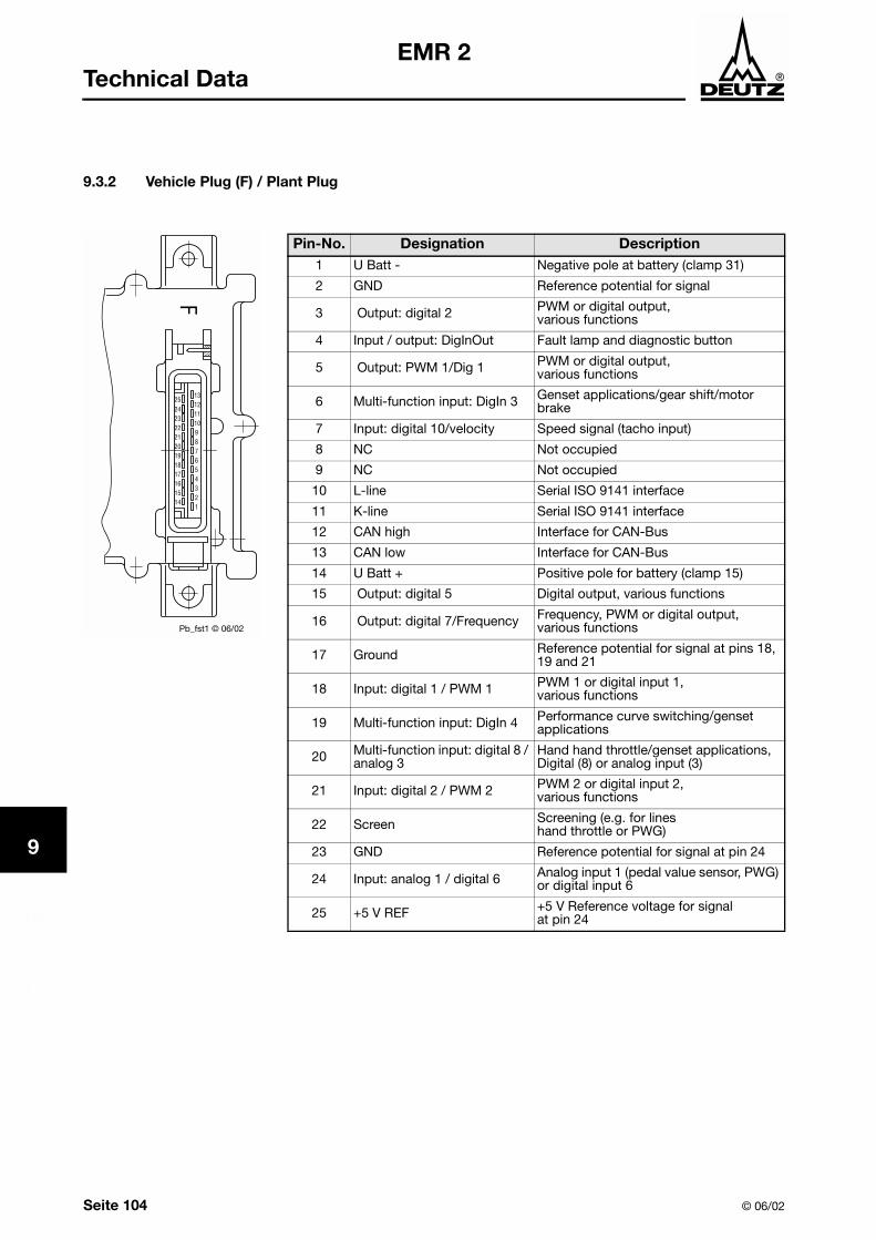
1
2
3
4
5
6
7
8
9
10
11
12
12
Seite 104 © 06/02
EMR 2Technical Data
9.3.2 Vehicle Plug (F) / Plant Plug
Pin-No. Designation Description1 U Batt - Negative pole at battery (clamp 31)
2 GND Reference potential for signal
3 Output: digital 2 PWM or digital output, various functions
4 Input / output: DigInOut Fault lamp and diagnostic button
5 Output: PWM 1/Dig 1 PWM or digital output, various functions
6 Multi-function input: DigIn 3 Genset applications/gear shift/motor brake
7 Input: digital 10/velocity Speed signal (tacho input)
8 NC Not occupied
9 NC Not occupied
10 L-line Serial ISO 9141 interface
11 K-line Serial ISO 9141 interface
12 CAN high Interface for CAN-Bus
13 CAN low Interface for CAN-Bus
14 U Batt + Positive pole for battery (clamp 15)
15 Output: digital 5 Digital output, various functions
16 Output: digital 7/Frequency Frequency, PWM or digital output, various functions
17 Ground Reference potential for signal at pins 18, 19 and 21
18 Input: digital 1 / PWM 1 PWM 1 or digital input 1,various functions
19 Multi-function input: DigIn 4 Performance curve switching/genset applications
20 Multi-function input: digital 8 / analog 3
Hand hand throttle/genset applications, Digital (8) or analog input (3)
21 Input: digital 2 / PWM 2 PWM 2 or digital input 2,various functions
22 Screen Screening (e.g. for lines hand throttle or PWG)
23 GND Reference potential for signal at pin 24
24 Input: analog 1 / digital 6 Analog input 1 (pedal value sensor, PWG) or digital input 6
25 +5 V REF +5 V Reference voltage for signal at pin 24
Pb_fst1 © 06/02

© 06/02 Page 105
1
2
3
4
5
6
7
8
9
10
11
12
13
EMR 2Technical Data
9.4 Sensor Data
Temperature sensor (NTC), coolant
Pins: Signal pin 9, GND pin 8, engine plug
Measuring range: -40 °C to 130 °C
Temperature sensor (NTC), fuel
Pins: Signal pin 5, GND pin 8, engine plug
Measuring range: -40 °C to 130 °C
Temperature sensor (NTC), charge air
Pins: Signal pin 4, GND pin 8, engine plug
Measuring range: -40 °C to 130 °C
Oil pressure sensor
Pins: Signal pin 21, GND pin 20, reference voltage +5 V pin 22, engine plug
Measuring range: 0 to 10 bar
Output signal: 0.5 V to 4.5 V DC
Charge air pressure sensor
Pins: Signal pin 24, GND pin 23, reference voltage +5 V pin 25, engine plug
Measuring range: 0.5 to 4 bar
Output signal: 0.5 V to 4.5 V DC
Speed sensor
Measuring range: 30 to 4,500 1/min
1st speed:
Conn. locality: camshaft, wheel box
Pins: Signal pin 13, GND pin 12, engine plug
- 44 Impulse/camshafts-revolutions for model series 1012/2012
- 48 Impulse/camshafts-revolutions for model series 1013/2013
- 167 Impulse/camshafts-revolutions for model series 1015
2nd speed (optional):
Conn. locality SAE-housing, crankshaft
Pins: Signal pin 11, GND pin 10, engine plug
- 129 Impulse/crankshafts-revolutions for model series 1012/1013
- Clamp w (dynamo impulses)

1
2
3
4
5
6
7
8
9
10
11
12
12
Seite 106 © 06/02
EMR 2Technical Data
Coolant level sensor
Pins: Signal pin 6, GND pin 8, engine plug
Measuring range:
Atmospheric pressure sensor
Depending on unit configuration, integrated into control unit, see Chapter 4.13

© 06/02 Page 107
1
2
3
4
5
6
7
8
9
10
11
12
13
EMR 2Index of Specialist Terms
10 Index of Specialist Terms
AGR Exhaust gas return
Actuator Actuator
AMP plug Multi-pole plug of the AMP company
Baud rate Data transmission speed [Bit/s]
CAN-Bus Interface (Controler Area Network)
EDC-actuator Actuator of the Bosch company
EEPROM Memory module in the microprocessor
EER 2 Electronic engine governer
ELTAB Electronic engine pocket handbook
EMV Electromagnetic compatibility
F-plug Vehicle plug / plant-side plug at the control unit
GND Mass (Ground)
High Switch open (high)
ISO International Standard Organization
Clamp 31 Minus clamp at battery
KLU Scope of customer supply
KM-temperature Coolant temperature
LDA Charge air pressure dependent full load stop
Limp home Emergency running features
Load dump Noise limit
Low Switch closed (low)
M-plug Engine plug
Md Torque
NC Not assigned
NTC Negative temperature coefficient
P-grad Proportional gradient; P-grad = 0 (Isochronous); P-grad adjustable (Droop).
PID control Proportional, integral, differential parts of the control
Pin Plug pin
Pull-up resistance Resistance to supply voltage
PWM-signal Pulse width modulated signal
REF Reference voltage or potential
SERDIA DEUTZ service diagnosis software with interface
Setpoint Setpoint
SWG 1/2 Setpoint sensor 1/2

1
2
3
4
5
6
7
8
9
10
11
12
12
Page 108 © 06/02
EMR 2Index of Specialist Terms

© 06/02 Seite 109
1
2
3
4
5
6
7
8
9
10
11
12
13
EMR 2Index
11 Index
A
Actuator ..................................................................................................................................................... 100Actuator functions ....................................................................................................................................... 86Altitude correction ....................................................................................................................................... 82Atmospheric pressure sensor .............................................................................................................. 82, 106
B
basic equipment .............................................................................................................................. 70, 71, 72Blink codes .................................................................................................................................................. 90
C
CAN-Bus ...................................................................................................................................................... 86CAN-Bus interface ....................................................................................................................................... 83Charge air monitoring .................................................................................................................................. 81Charge air pressure sensor ........................................................................................................................ 105Cold start installation ................................................................................................................................... 82Configuration ............................................................................................................................................... 85Configuration example ................................................................................................................................. 86Connection diagrams ................................................................................................................................. 113Coolant level sensor .................................................................................................................................. 106Coolant monitoring ...................................................................................................................................... 82Coolant temperature monitoring .................................................................................................................. 81
D
Damages ...................................................................................................................................................... 67Default functions .......................................................................................................................................... 86Description of functions ............................................................................................................................... 70Diagnostic button ........................................................................................................................................ 87Diagnostic interface ............................................................................................................................... 83, 86Display / output functions ............................................................................................................................ 86Displays ....................................................................................................................................................... 79Droop control ............................................................................................................................................... 78
E
Electrical welding ......................................................................................................................................... 68Emergency running ...................................................................................................................................... 82Engine plug ................................................................................................................................................ 103Engine protection functions ......................................................................................................................... 81Engine-start/stop ......................................................................................................................................... 78Error code .................................................................................................................................................... 90Excess speed protection ............................................................................................................................. 75

1
2
3
4
5
6
7
8
9
10
11
12
13
Seite 110 © 06/02
EMR 2Index
F
Fault blink code overview ............................................................................................................................ 93Fault group ................................................................................................................................................... 93Fault indicator lamp ..................................................................................................................................... 87Fault lamp .................................................................................................................................................... 79Fault locality/fault description ...................................................................................................................... 93Fault memory ............................................................................................................................................... 92Fault no. ....................................................................................................................................................... 93Fuel quantity limitation (performance curve) ................................................................................................ 77Fuel volume control ..................................................................................................................................... 82Function control ........................................................................................................................................... 89Function extensions ..................................................................................................................................... 73Function overview ........................................................................................................................................ 86Functions ..................................................................................................................................................... 86
I
Important notes ........................................................................................................................................... 67Installation guidelines .................................................................................................................................. 67Interfaces ............................................................................................................................................. 83, 102Introduction .................................................................................................................................................. 65
L
LDA function ................................................................................................................................................ 81Limp home ................................................................................................................................................... 82Load collective ............................................................................................................................................. 80
M
Memory functions ........................................................................................................................................ 86Min/Max control ........................................................................................................................................... 74Monitoring function ...................................................................................................................................... 79
N
Notes ........................................................................................................................................................... 65
O
Oil pressure monitoring ................................................................................................................................ 81Oil pressure sensor .................................................................................................................................... 105Operating instructions ................................................................................................................................. 67Output signals .............................................................................................................................................. 79Outputs ................................................................................................................................................ 79, 102
P
Parameter setting ......................................................................................................................................... 85Pin .............................................................................................................................................................. 102Pin assignment ............................................................................................................................................ 86Pin type ...................................................................................................................................................... 102Plant plug ................................................................................................................................................... 104Plug assignments ...................................................................................................................................... 103Plug connection ........................................................................................................................................... 68

© 06/02 Seite 111
1
2
3
4
5
6
7
8
9
10
11
12
13
EMR 2Index
R
Replacement of system components .......................................................................................................... 99
S
Scope of function ........................................................................................................................................ 86Second speed input ..................................................................................................................................... 75Self-diagnostic ............................................................................................................................................. 87Sensor data ................................................................................................................................................ 105Sensor inputs ............................................................................................................................................... 86SERDIA ........................................................................................................................................................ 98Set point settings ......................................................................................................................................... 76Signal specification .................................................................................................................................... 102Signal type ................................................................................................................................................. 102Software ....................................................................................................................................................... 98Speed control .............................................................................................................................................. 74Speed sensor ............................................................................................................................................. 105Speed throttling ........................................................................................................................................... 81Switchable speed functions ......................................................................................................................... 75System description ...................................................................................................................................... 69System functions ......................................................................................................................................... 71System overview .......................................................................................................................................... 69
T
Technical data ........................................................................................................................................... 101Temperature sensor (NTC), charge air ....................................................................................................... 105Temperature sensor (NTC), coolant ........................................................................................................... 105Temperature sensor (NTC), fuel ................................................................................................................. 105Temperature-dependent start control ......................................................................................................... 81
U
Utilization of the EMR 2 ............................................................................................................................... 69
V
Variable speed regulation ............................................................................................................................ 74Vehicle plug ............................................................................................................................................... 104
W
Wiring ........................................................................................................................................................... 68

1
2
3
4
5
6
7
8
9
10
11
12
13
Seite 112 © 06/02
EMR 2Index

© 06/02 Page 113
1
2
3
4
5
6
7
8
9
10
11
12
13
EMR 2Connection diagrams
12 Connection diagrams
The following connection diagrams present the maximum scope of the EMR2. Customer or model-specificwishes are not taken into account.
12.1 Connection diagram vehicle / plant side
12.2 Connection diagram vehicle side (sheet 1)
12.3 Connection diagram vehicle side (sheet 2)
12.4 Connection diagram for CAN-Bus and diagnostic line
Only the switching diagram specific for the particular engine is binding. This is prepared by the DEUTZcustomer representative before supply of the first engine as the switching diagram is not part of the docu-mentation supplied with the engine.
Methods of obtaining the switching diagrams are:
! Sales or customer representative, or
! Dept. Sales Documentation (Format DIN-A2) or
! Sales drawing CD-ROM or
! Engine pocket handbook (from page 3.150, size DIN-A4) or
! ELTAB CD-ROM


© 06/02 Seite/Page 115
EMR 2 Anhang/Appendix
12.1 Anschlussplan Fahrzeug-/Anlagenseite Connection diagram - Vehicle side / Unit side
geraeteseite © 06/02

Seite/Page 116 © 06/02
EMR 2AnhangAppendix
12.2 Anschlussplan Motorseite (Blatt 1) Connection diagram - Engine side (sheet 1)
motorseite1 © 06/02

© 06/02 Seite/Page 117
EMR 2 Anhang/Appendix
12.3 Anschlussplan Motorseite (Blatt 2) Connection diagram - Engine side (sheet 2)
motorseite2 © 06/02

Seite/Page 118 © 06/02
EMR 2AnhangAppendix
12.4 Anschlussplan für CAN-Bus und Diagnoseleitung Connection Diagram for CAN-Bus and Diagnostic Line
emsemr2 © 06/02