system components - motion control - power jacks
TRANSCRIPT
www.powerjacks.com
System Components
Motion Control

1
motion control
sectioneight
Contents
8. Motion Control 2
8.1. Rotary Limit Switches 2
8.2. Proximity and Contact Limit Switches 10
8.3. Encoders 14
8.4. Position Indicators 18
8.5. Control Panels 20
2
motion control
sectioneight
8.1. Rotary Limit Switches
8.1.1. RLS-51 Rotary Limit Switches
8.1.1.1. RLS-51 Rotary Cam Limit Switch Overview
Power Jacks products are used in a wide spectrum of industries for lifting, positioning and materials handling applications. All of whichrequire a level of motion control.
Power Jacks RLS-51 series geared cam limit switches are ideal for use as:
• End of travel limit switches to stop or reverse an actuator system.
• Mid travel signal providers to allow integration of other process operations.
And allow integration of other feedback devices such as potentiometers and encoders inside their compact housing.
RLS-51 Features include:
1. Useable revolutions from 4 to 16000.
2. 2 to 8 position limit switches.
3. Enclosure IP66 as standard.
4. Mounting options for B14 face, B5 flange and B3 foot mounted.
5. Available in three voltages 250 VAC, 24 VDC and 80 VDC.
6. Modular design to allow a wide variety of options.
7. Operating temperature: -40ºC → +80ºC.
8.1.1.1.1. Illustrated Examples
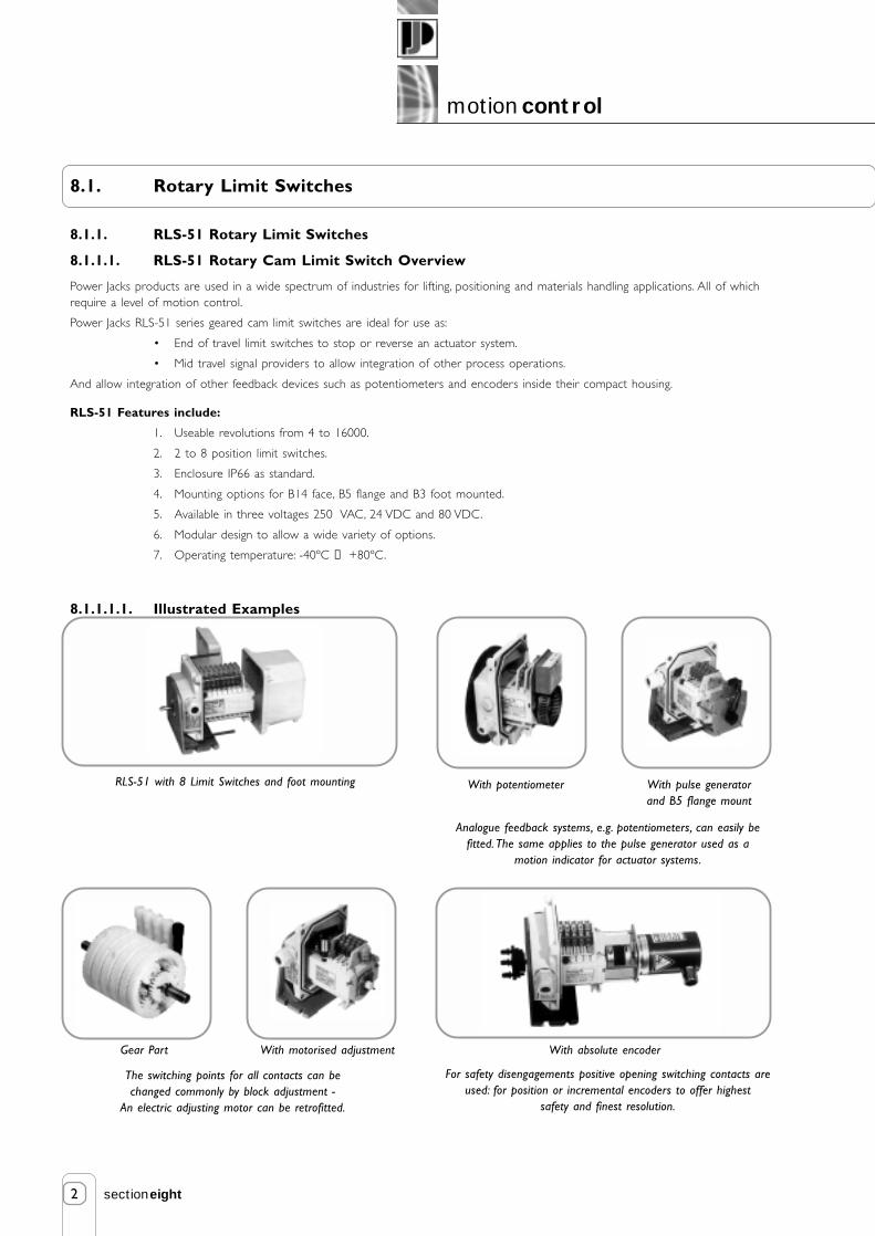
RLS-51 with 8 Limit Switches and foot mounting
The switching points for all contacts can bechanged commonly by block adjustment -
An electric adjusting motor can be retrofitted.
Analogue feedback systems, e.g. potentiometers, can easily befitted. The same applies to the pulse generator used as a
motion indicator for actuator systems.
For safety disengagements positive opening switching contacts areused: for position or incremental encoders to offer highest
safety and finest resolution.
With motorised adjustmentGear Part
With pulse generatorand B5 flange mount
With potentiometer
With absolute encoder
3
motion control
sectioneight
8.1.1.2. RLS-51 Features and Options
The RLS-51 geared cam limit switches are universal mechanical switching devices that have been designed for use in conjunction withcam discs on a specific angle of rotation for the indication of a large number of shaft revolutions. These cam discs serve to operatemechanical contacts.
Design features include:
• Low Friction Planetary Gearing with irreversable, self-locking worm adjustment of the cam discs.
• Fixed Cam Adjustment in the housing. The adjusting worms of the cam discs are arranged so that they can beaccessed from the same direction as the contact connections for optimal accessibility in confined conditions.Adjustment is possible during operation. The simplicity and accuracy of the cam adjustment is unsurpassed.
• Block Adjustment of all switching contacts jointly is made possible by a single adjusting worm (black) without theswitching points of individual switching contacts being altered with respect to each other.
• Large Cam Disc Diameter for good adjustability and high switching point repeat accuracy.
• Reinforced Polycarbonate Housing as standard with IP66 protection and a wide operating temperature range.
• Modular Design allows adaptation to suit individual requirements via intermediate pieces.
• Maintenance Free gearbox components.
Options
• Position indicating plate for block adjustment.
• Potentiometer feedback drives (2 available) to suit single and multi-turn potentiometers.
• Pulse transmitter with 50 pulses per revolution.
• Anti-condensation heater to prevent condensation and excessively low temperatures in switches.
• Motor driven contact block adjuster.
• Mounting for encoders (incremental and absolute).
• Extended drive shaft for feedback devices.
• Aluminium housing for harsh environments and fitment of large and heavy encoders, IP 65 enclosure.
• Cam discs with a 40O cam angle can be provided at no extra cost. Standard is 15O cam angle. Other angles can bemanufactured at extra cost on request. Note different cam angles alter the number of useable revolutions from thestandard. The 40O cam has less useable revolutions than a 15O cam, consult Power Jacks.
• Stage Technology Tested Unit can be provided to VBG 70 with test certificates. A 40O angle cam disc is used for thisapplication.
8.1.1.2.1. RLS-51 Coupling Note
The ideal drive for the limit switch is transmitted by torsionally stiff, flexible coupling with low axial and radial restoring forces. Therebymisalignment and axial displacement are balanced. For radial load rating and coupling advice consult Power Jacks.
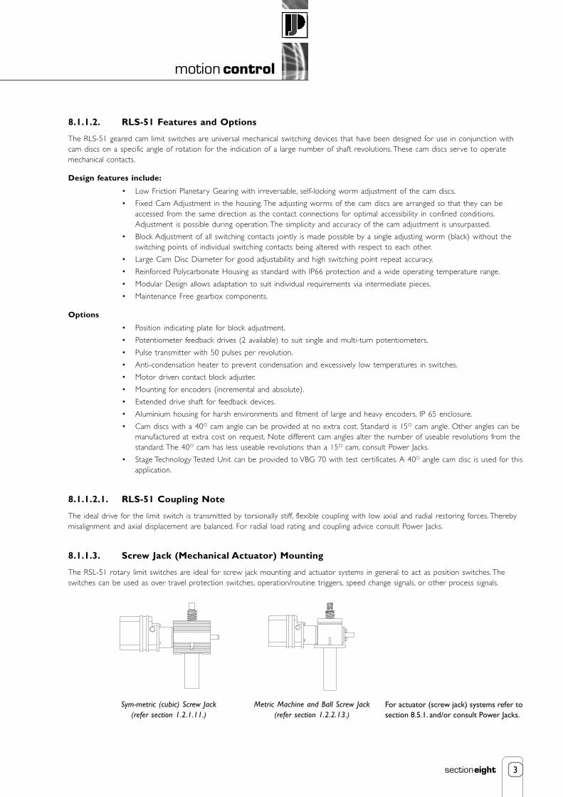
8.1.1.3. Screw Jack (Mechanical Actuator) Mounting
The RSL-51 rotary limit switches are ideal for screw jack mounting and actuator systems in general to act as position switches. Theswitches can be used as over travel protection switches, operation/routine triggers, speed change signals, or other process signals.
For actuator (screw jack) systems refer tosection 8.5.1. and/or consult Power Jacks.
Sym-metric (cubic) Screw Jack(refer section 1.2.1.11.)
Metric Machine and Ball Screw Jack(refer section 1.2.2.13.)

4
motion control
sectioneight
8.1.1.4. RLS-51 Performance
Contactdesignation
Contact type Contactmaterial
92
97 ➁
99L
99P
96
Silver
Gold
Silver
Silver
Silver
Yes
Yes
Yes
Yes
Yes
6
6
6
3
6
250
250
250
250
250
6
6
3
3
6
2
2
2
2
2
10
10
10
10
10
Snapaction
Snapaction
Snapaction
Snapaction
Snapaction
Screwterminal
Screwterminal
Printedcard
Flat plug6.3
Screwterminal
Change-overswitch
Change-overswitch
Change-overswitch
Change-overswitch
➀ DC switching capacity with T = 0 ms (pure resistive load) DC switching capacity with inductive load on request➁ Contact 97 for SPC applications (gold contacts)
Type ofcontact
connection
Switch Rating
AC 24V DC 80V DC
Amps AmpsAmps Volts
Positive opening toVDE0660 part 200
from 7.92EN60947T5-1
Switchactuation
Mec. life inmillions ofswitching
operations
Normallyclosed contact
Change over switch
92
97
99L
99P
(12, 22, . . .) (14, 24, . . .)
(11, 21, . . .)
2
1
4
Normally closed contact
96
(12, 22, . . .)
(11, 21, . . .)
2
1
* Caution! Due to the slow actuation speed of the switching contacts caused by the high gear reductions, the change-over behaviour of the contacts is affected negatively.
From gear size 6 it is therefore recommended to use only the normally - closed contacts of the switches.Before using analogue feedback systems (e.g. potentiometer) please consult our technical department.
GearSize
Usable revs.
selected
Usable revs.theoretical
with 15° camdiscs
4.166.8811.2317.8429.548.1376.45126.39206.26327.6541.5883.81403.72320.23787.16014.779942.216227.6
4.16.511
17.529.048751252053235408801384228837355900980016000
1
2
3
4
5
6
Input/output stage
1 rev. of thedrive shaft -
corresp. to anang. motion
of cam disc =°
No ofin-termstages
Change - overcontact resetrev. at driving
shaft
Max drivespeed(RPM)
Gear Ratio
4.2857.08311.5618.36130.3549.53878.678130.054212.272337.135557.284909.591444.622387.963897.586190.20410232.40716701.17
1 x 4.2851 x 4.2851 x 4.2852 x 4.2852 x 4.2852 x 4.2853 x 4.2853 x 4.2853 x 4.2854 x 4.2854 x 4.2854 x 4.2855 x 4.2855 x 4.2855 x 4.2856 x 4.2856 x 4.2856 x 4.285
-1.6532.698
-1.6532.698
-1.6532.698
-1.6532.698
-1.6532.698
-1.6532.698
100012001500180018001800180018001800180018001800180018001800180018001800
0.007140.01180.01930.03060.05050.08250.1310.21660.35360.56160.92841.5152.4063.9786.49310.31317.04727.824
8450.831.1419.611.867.274.572.771.691.060.650.40.250.150.090.060.040.02
Min driveshaft speed(only for
change - overcontact)
0.671.11.82.94.77.712.220.2335287141224371606***
8.1.1.5. Switching Contacts
The contacts can either be connected through screw terminals for a cable cross section of 0.75 mm2 to 1.5 mm2 or through flat plugs6.3 x 0.8 mm or through a printed card with cage tension spring terminals for a cross section of 0.14 to 2.5 mm2.
For contacts with
flat-plug connection, insulated flat - plug receptables must be used at voltages above 25V AC and 60 VDC.
5
motion control
sectioneight
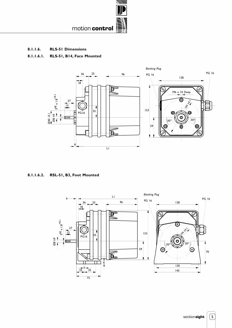
8.1.1.6. RLS-51 Dimensions
8.1.1.6.1. RLS-51, B14, Face Mounted
8.1.1.6.2. RSL-51, B3, Foot Mounted
6
18
36 25 96
35
59
153
9
70
725 35
75
27
15
Ø8
h9
3pg x
1.8
+0.
1
PG16
130
145
128
30O 30O
104
±0.1
L1
18
36 25 96
27
15
Ø40
-0.
1
Ø8
h93pg
x 1
.8+
0.1
PG1635 153
128
PG 16
Blanking Plug
30O
59
PG 16
30O
L16
Blanking Plug
PG 16PG 16
104
±0.1
M6 x 10 Deep
6
motion control
sectioneight
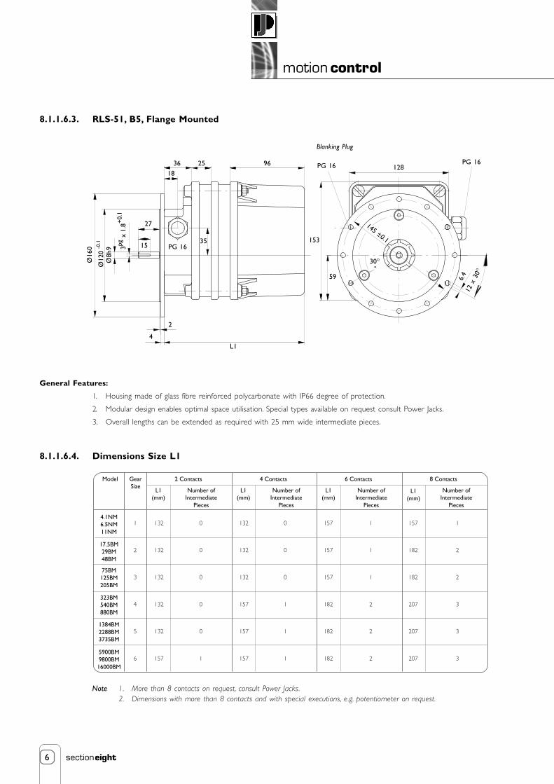
8.1.1.6.3. RLS-51, B5, Flange Mounted
General Features:
1. Housing made of glass fibre reinforced polycarbonate with IP66 degree of protection.
2. Modular design enables optimal space utilisation. Special types available on request consult Power Jacks.
3. Overall lengths can be extended as required with 25 mm wide intermediate pieces.
8.1.1.6.4. Dimensions Size L1
1836 25 96
35
59
153
4
2
27
15
Ø16
0
Ø12
0 -0.
1
PG 16
30O
145 ±0.1
Ø8h
9 3pg x
1.8
+0.
1
L1
6.4
12 x
30
O
128PG 16
Blanking Plug
PG 16
Model GearSize
L1(mm)
Number ofIntermediate
Pieces
2 Contacts
4.1NM6.5NM11NM
17.5BM29BM48BM
75BM125BM205BM
323BM540BM880BM
1384BM2288BM3735BM
5900BM9800BM16000BM
1
2
3
4
5
6
132
132
132
132
132
157
132
132
132
157
157
157
0
0
0
0
0
1
0
0
0
1
1
1
157
157
157
182
182
182
1
1
1
2
2
2
157
182
182
207
207
207
1
2
2
3
3
3
L1(mm)
Number ofIntermediate
Pieces
L1(mm)
Number ofIntermediate
Pieces
L1(mm)
Number ofIntermediate
Pieces
4 Contacts 6 Contacts 8 Contacts
Note 1. More than 8 contacts on request, consult Power Jacks.2. Dimensions with more than 8 contacts and with special executions, e.g. potentiometer on request.

7
motion control
sectioneight
8.1.2. SKA Rotary Limit Switches
8.1.2.1. SKA Rotary Limit Switch Features
• 2 Limit Switches.
• Available in three voltage ratings - 250, 480 or 600 Volt.
• Available in three gear ratios.
• Sturdy and compact.
• Constructed of corrosion resistant materials, with housing of anodised aluminium.
• Simple to adjust. Two micro-switches, one for up/stop and one for down/stop, are activated by the adjustable limitswitch nuts which travel laterally when the internal screw is rotated through gear reduction.
• Enclosure IP65 (NEMA-4).
• Lifetime lubricated.
• Operating temperature range: -29ºC → +65ºC (-20ºF → +150ºF).
• Designed especially for all Power Jacks machine screw and ball screw actuators.
• Bolts on to all Power Jacks actuators except 5kN and 10kN Metric, 1/4, 1/2 and 1 Ton Imperial and Micro-Miniatureactuators were the limit switch has to be mounted separately and shaft driven.
• Optional 4-position limit switch available. Consult Power Jacks for details.
Screw Limit Switch Nut
Microswitches
Input shaft 0.300” Nut Dia
8
motion control
sectioneight
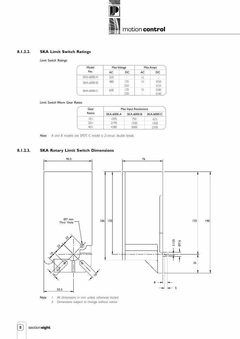
8.1.2.2. SKA Limit Switch Ratings
Note A and B models are SPDT; C model is 2-circuit, double break.
8.1.2.3. SKA Rotary Limit Switch Dimensions
Note 1. All dimensions in mm unless otherwise stated.2. Dimensions subject to change without notice.
Ø7 mmThro’ Hole
555.5
23
7690.5
23
14
1010
8
155166
3.12
5
Ø7.
6
35
155 190
Limit Switch Ratings
Limit Switch Worm Gear Ratios
ModelNo.
SKA-6000-A
SKA-6000-B
SKA-6000-C
AC DC AC DC
250
480-
600-
-125250125230
1515-
15-
-0.500.250.800.40
Max Voltage Max Amps
GearRatios
10:120:140:1
Max Input Revolutions
SKA-6000-A SKA-6000-B SKA-6000-C
109521904380
75015003000
67513502700

9
motion control
sectioneight
Wiring Diagram"A" & "B" Model
Wiring Diagram"C" Models
1 Caution: Disconnect powerbefore makingany adjustment.
2 Check drift before adjusting limits.
3 Remove screw “A” and nut guide keeper“B” to adjust limits.
4 Run actuator unit to desired limit.
5 Rotate appropriate nut until switch clicks,then turn 1/2 turn more.
6 Replace “A” and “B”.
7 Run actuator unit to the other limit.
8 Repeat steps 2, 4 and 5 to adjust this nut.
8.1.2.5. SKA Electric Limit Switch Specifications
3 9/
16”
8.1.2.4. SKA Limit Switch Screw Jack (Mechanical Acutator) Mounting
The SKA rotary limit switch is an ideal compact limit switch formounting on a screw jack (mechanical actuator). The units aretypically used for over travel protection. The SKA units can beinstalled with either “close” or “extended” mountings. Closemounting has to be done at the factory but extended mountingcan be done in the field.
For full details on screw jack (mechancical actuator) mountingrefer to the following options:
Metric Machine or Ball Screw Jacks - refer section 1.2.1.14.
Imperial Machine or Ball Screw Jacks - refer section 1.2.3.11.
8.1.2.5. Ordering the Right SKA Limit Switch
To ensure that the limit switch has sufficient travel capability for the actuator unit, use the following formula:
Max. Input Revolutions
Turns of Actuator Worm per mm (inch) of RaiseMax raise of actuator model in mm (inches =
Note For water-tight connection, use a weather-tight connector and sealant around the threads.Limit switches will be damaged if over travelled.For shipping purposes, the 0.5” NPT hole is closed with a plastic plug, which is not water tight.
Note NO = Normally Open NC = Normally Closed
Electric Limit Switch Specifications
Max.Voltage
SKA-6000-A-10SKA-6000-A-20SKA-6000-A-40SKA-6000-B-10SKA-6000-B-20SKA-6000-B-40SKA-6000-C-10SKA-6000-C-20SKA-6000-C-40
TPU = Turns Per Unit of raise of actuator model, where Unit = millimetre or inches.
Max. Amps Max.Worm Rev.AC
250
480
120240480800
DC
125250
115230
AC
15
15
15
DC
0.500.25
0.800.40
1095219043807501500300067513502700
Max.Raise
1095/TPU2190/TPU4380/TPU750/TPU1500/TPU3000/TPU675/TPU1350/TPU2700/TPU
Max.Allowable Drift
24/TPU48/TPU96/TPU29/TPU57/TPU115/TPU38.5/TPU77/TPU154/TPU
NotchAdjustment
1/TPU2/TPU4/TPU1/TPU2/TPU4/TPU1/TPU2/TPU4/TPU
Model No.
Slight adjustments may be necessary. See chartbelow for notch adjustment value.
NONONONO NC NCNC NC
CB A AB
6 5/8”
6 1/4”
1/2 N.P.T.

10
motion control
sectioneight
8.2. Proximity and Contact Limit Switches
8.2.1. Proximity Sensors
• Inductive Proximity Sensors.
• Non-contact, so no wearing parts.
• 2 Wire sensor for either Normally Closed (NC) orNormally Open (NO) switching.
• Long sensing range.
• Rugged one-piece Metal housing.• Optical setting aid with 2 LED colour settings:-
Red LED indicates just in sensing range.Yellow LED only indicates within 80% safe sensing range.
• M12 Plug in connection for fast change-ability.
• M12 sockets available straight or angled with5 m cable.
• Full 360° visibility for switching with 4 yellow LED’sat 90° offset.
• Flush face as standard, non-flush available.
• Housing plated brass, Stainless Steel available on request.• Operating voltage 10 → 30 VDC.
• Enclosure IP67.
• Operating temperature -25°C → +70°C• Other types available on request. Consult power Jacks.
• Ideal for screw jack or linear actuator mounting.
L
Model
Electrical DesignOutputOperating Voltage (V)Current Rating (mA)Minimum Load Current (mA)Short-circuit ProtectionReverse Polarity ProtectionOverload ProtectionVoltage Drop (V)Leakage Current (mA)Operating Distance (mm)Switch-point Drift (%/Sr)Hysteresis (%/Sr)Switching Frequency (Hz)Correction Factors (approx.)Mild SteelStainless SteelBrassAluminiumCopperFunction DisplaySwitching Status LEDSetting Aid LEDOperating Temperature (°C)ProtectionEMCHousing MaterialConnection
M18
DC PNP/NPNnormally open/closed programmable
10 → 36 DC1004
YesYesYes
< 4.6< 1
0 → 6.48
3 → 20250
10.70.450.40.33
yellow (4 x 90°)red
-25 → +70IP 67
EN 60947-5-2; EN 55011 class Bbrass; special coated; CO-PC
M12 connector
M12
0 → 3.25
400
10.70.40.370.25
M30
0 →12.1
200
10.70.50.50.4
2 1
3 4
1
4
L+
L-
4
1
L+
L-
Sensor
Sensing Range (flush)
Overall Length, L
M12
4 mm
62 mm
M18
8 mm
72 mm
M30
15 mm
72 mm

11
motion control
sectioneight
8.2.2. Compact Electro-Mechanical Contact Limit Switches
8.2.2.1. Compact Contact Limit Switch Overview
• Compact electro-mechanical limit switch.
• Study metal enclosure
• Pre-cabled unit.
• High end enclosure protection IP67.
• Available with plug-in connector.
• Other sizes and acutation heads are available on request.Consult Power Jacks.
• Ideal for scew jack or linear actuator mounting.
8.2.2.2. Compact Contact Limit Switch Technical Data
16
86.4
E E
30
51(1)
35.4
4
M12 x 1
Ø10.6Ø10.6
30
51(1)
35.4
16
86.4
4
M12 x 1
Note 1. All dimensions in mm unless otherwise stated.2. Dimensions subject to change without notice.3. For dimensions of other switches consult Power Jacks.4. For a full switch data sheet consult Power Jacks.
8.2.2.3. Compact Contact Limit Switch Dimensions
Item
Housing
Pre-cabled
Switch type
Switch actuation
Max actuation speed
Mechanical durability
Ambient temperatureOperationStorage
Product conformity
Enclosure
Operating characteristics
Insulation voltage
Description
Metal, compact hosuing, totally enclosed and sealed
2m PVC cable 5 x 0.75mm2 (other cable lengths available on request)
Single pole, 1 change-over, snap action
Steel Roller Plungera Lateral Cam Approach CSL-RPTLb Travers Cam Approach CSL-RPTT
0.5 m/s
10 million operating cycles
-25°C → +77°C-40°C → +70°C
IEC947-5-1
IP67
AC - 15; B300 (UE = 240V, le = 1.5A)DC - 13; R300 (UE = 240V, le = 0.1A)
Ui = 300V
CLS-RPTL(a)
CLS-RPTT(b)
E = 8 mm Max, Clearance Diameter Ø12.5 mm
(1) = Ø8 mm Cable
BK-WH
GN
YE
BN
BK
BU

12
motion control
sectioneight
8.2.3. Safety Related Electro-Mechanical Contact Limit Switches
8.2.3.1. Safety Related Contact Limit Switch Overview
• Positive break Normally Closed contacts - will not stick or weld shut.
• Watertight design to IP67 washdown requirements.
• Rugged corrosion resistant housing tolerants hostile environments.
• Safety system approved.
• Thermoplastic enclosure. Double insulated.
• Snap action with positive-break Normally Closed contact, approved for use insafety systems.
• Wiring compartment.
• Alternative actuators heads are available on request. Consult Power Jacks.
• Actuator heads can be repositioned in steps 4 x 90°
• Good resistance to oil and petroleum spirit.
• Actuating force: Min. 9 N.
• Positive break force: 19 N.
• Actuating speed with actuating angle 30° to switch axis. Snap action: Min. 20 mm/min, max. 1 m/s.
• Cable entry: Long Body - 1 cable entry, at end. Short Body - 2 cable entries from sides.
• Ideal for screw jack or linear actuator mounting.
8.2.3.2. Safety Related Contact Limit Switch Specification
** For the switch plunger.
Note 1. Technical Data subject to change without notice.2. For a full set of limit switch details consult Power Jacks.
Feature Description
Standards IEC/EN 60947-5-1; EN 1088; BG-GS-ET-15
Design EN 50047
Enclosure material Glass-fibre reinforced thermoplastic, self-extinguishing
Protection class IP 67 to IEC/EN 60529/DIN VDE 0470-1
Contact material Silver
Contact type Change-over with double break Zb, NC contacts with positive break
Switching system A IEC 60947-5-1; B BG-GS-ET-15; snap action, NC contacts with positive break
Termination Screw terminals for max. 2.5 mm2 cables (including conductor ferrules)
Rated impulse withstand voltage U imp 6 kV
Rated insulation voltage U i 500 V
Thermal test current I th 10 A
Utilisation category AC-15; DC-13
Rated operating current/voltage Ie/Ue 4 A/230 VAC; 2.5 A/400 VAC; 1 A/500 VAC; 1 A/24 VDC
Max. fuse rating 10 A (slow blow); 16 A (quick blow),
6 A (slow blow) as positive break position switch
Ambient temperature -30 °C → +80 °CMechanical life 20 million operations
Switching frequency Max. 5,000/h
Switching point accuracy -
Actuating speed ** Min. 10 mm/min
Contact break for complete stroke 2 x 2 mm
Bounce duration < 3 ms
Switchover time > 5.5 ms
13
motion control
sectioneight
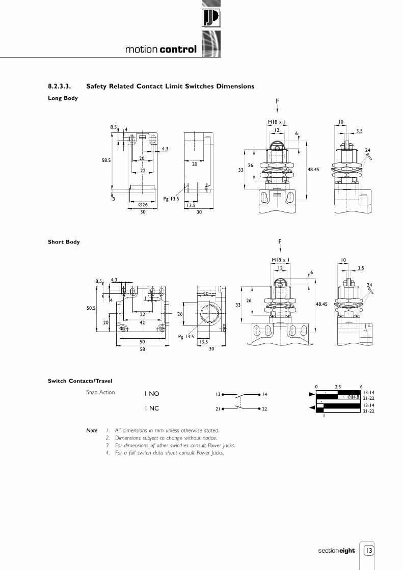
8.2.3.3. Safety Related Contact Limit Switches Dimensions
Long Body
Short Body
Switch Contacts/Travel
Snap Action
Note 1. All dimensions in mm unless otherwise stated.2. Dimensions subject to change without notice.3. For dimensions of other switches consult Power Jacks.4. For a full switch data sheet consult Power Jacks.
0
13
21
14
22
1 NO
1 NC
2,5
1
4.8
613-1421-22
13-1421-22
p
58.5
3
30Ø26
22
20
4.3
48.5
Pg 13.513.5
30
2033
2648.45
M18 x 1
126
24
3.5
10
F
8.5
20
58
50
22 26
4
4.3
Pg 13.513.5
30
20
3326
48.45
M18 x 1
126
24
3.5
10
1
50.5
F
42
14
motion control
sectioneight
8.3. Encoders
8.3.1. Incremental Encoders
8.3.1.1. Incremental Encoder Features
• Simple zero-pulse assignment directly on the Encoder by pressing a button.
• Long service life of the LED by using automatic light regulation.
• Maximum reliability using opto-ASICs with chip-on-board technology.
• Any number of desired lines from 1 → 8192.
• RS422 or push-pull output drivers.
• Servo flange for 6 mm solid shaft.
• Face mount flange for 10 mm solid shaft.
• Connector or cable outlet.
• High degree of protection up to IP66.
• Interchangeable collets for hollow shaft diameters fromØ6 → Ø15 mm and Ø1/4 → Ø1/2 inch.
• Screw Jack and Electro-mechanical Linear Actuator mounting kits available.Consult Power Jacks for details
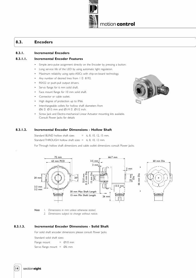
8.3.1.2. Incremental Encoder Dimensions - Hollow Shaft
Standard BLIND hollow shaft sizes = 6, 8, 10, 12, 15 mm.
Standard THROUGH hollow shaft sizes = 6, 8, 10, 12 mm.
For Through hollow shaft dimensions and cable outlet dimensions consult Power Jacks.
.
8.3.1.3. Incremental Encoder Dimensions - Solid Shaft
For solid shaft encoder dimensions please consult Power Jacks.
Standard solid shaft sizes:
Flange mount = Ø10 mm
Servo flange mount = Ø6 mm
Note 1. Dimensions in mm unless otherwise stated.2. Dimensions subject to change without notice.
72 mm
63 mm PCD
20 mm
3.3 mm3.2 mm
32.0
mm
31.5
mm
Dia
20°
26 mm
66.7 mm
22 m
mD
ia
66 m
m D
ia
60 mm Dia
2 mm
15 m
m D
ia(F
7)
13.5 mm
3.5 mm
2 mm
30 mm Max Shaft Length
15 mm Min Shaft Length
15
motion control
sectioneight
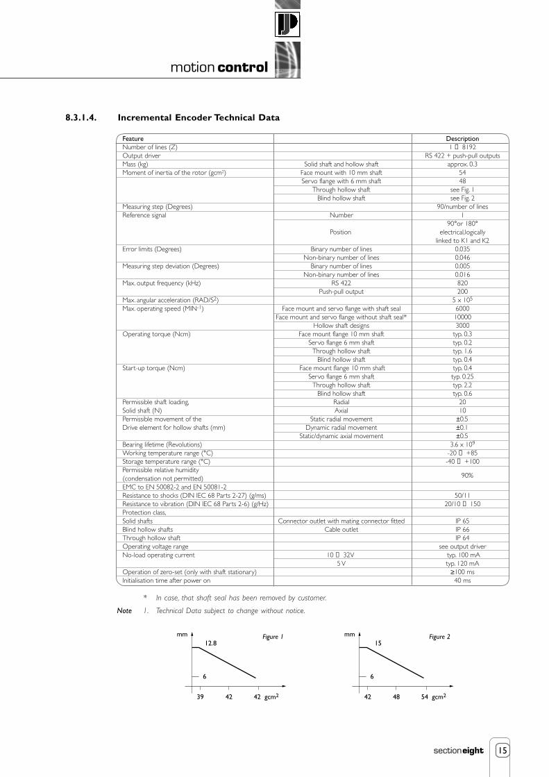
8.3.1.4. Incremental Encoder Technical Data
39 42 42 gcm2
12.8
6
mm Figure 1
42 48 54 gcm2
15
6
mm Figure 2
Feature DescriptionNumber of lines (Z) 1 → 8192Output driver RS 422 + push-pull outputsMass (kg) Solid shaft and hollow shaft approx. 0.3Moment of inertia of the rotor (gcm2) Face mount with 10 mm shaft 54
Servo flange with 6 mm shaft 48Through hollow shaft see Fig. 1
Blind hollow shaft see Fig. 2Measuring step (Degrees) 90/number of linesReference signal Number 1
90°or 180° electrical,logically
linked to K1 and K2Error limits (Degrees) Binary number of lines 0.035
Non-binary number of lines 0.046Measuring step deviation (Degrees) Binary number of lines 0.005 Non-binary number of lines 0.016Max. output frequency (kHz) RS 422 820
Push-pull output 200Max. angular acceleration (RAD/S2) 5 x 10⁵
Max. operating speed (MIN-1) Face mount and servo flange with shaft seal 6000Face mount and servo flange without shaft seal* 10000
Hollow shaft designs 3000Operating torque (Ncm) Face mount flange 10 mm shaft typ. 0.3
Servo flange 6 mm shaft typ. 0.2Through hollow shaft typ. 1.6
Blind hollow shaft typ. 0.4Start-up torque (Ncm) Face mount flange 10 mm shaft typ. 0.4
Servo flange 6 mm shaft typ. 0.25Through hollow shaft typ. 2.2
Blind hollow shaft typ. 0.6Permissible shaft loading, Radial 20Solid shaft (N) Axial 10Permissible movement of the Static radial movement ±0.5Drive element for hollow shafts (mm) Dynamic radial movement ±0.1
Static/dynamic axial movement ±0.5Bearing lifetime (Revolutions) 3.6 x 10⁹
Working temperature range (°C) -20 → +85Storage temperature range (°C) -40 → +100Permissible relative humidity(condensation not permitted)EMC to EN 50082-2 and EN 50081-2 Resistance to shocks (DIN IEC 68 Parts 2-27) (g/ms) 50/11Resistance to vibration (DIN IEC 68 Parts 2-6) (g/Hz) 20/10 → 150Protection class, Solid shafts Connector outlet with mating connector fitted IP 65Blind hollow shafts Cable outlet IP 66Through hollow shaft IP 64Operating voltage range see output driverNo-load operating current 10 → 32V typ. 100 mA 5 V typ. 120 mAOperation of zero-set (only with shaft stationary) ≥100 msInitialisation time after power on 40 ms
90%
Position
* In case, that shaft seal has been removed by customer.
Note 1. Technical Data subject to change without notice.

16
motion control
sectioneight
8.3.2. Absolute Encoders
8.3.2.1 Absolute Encoder Features
• Rugged, magnetic pick-up system.
• Rotary multiturn absolute encoder with integral gearbox, therefore a battery is not necessary.
• Basic resolution max. 8192 steps, 8192 revolutions.
• SSI, 25 bit (Synchronous Serial Interface).
• RS 422 configurable interface.
• Zero set push button.
• Electronically adjustable configurable interface.
• Compact dimensions.
• Highly shock-proof and vibration-proof.
• High degree of protection IP 67.
• Connector or cable outlet.
• Servo flange for 6 mm solid shaft.
• Face mount flange for 10 mm solid shaft.
• Blind hollow shaft: max. shaft diameter 15 mm. Option of using interchangeable collets, diametersfrom 6 to 12 mm, and 1/4 inch and 1/2 inch can be realised. Easy to install and no coupling needed.
• Screw Jack and Electro-mechanical Linear Actuator mounting kits available. Consult Power Jacks for details.
8.3.2.2. Absolute Encoder Dimensions - Hollow Shaft
8.3.2.3. Absolute Encoder Dimensions - Solid Shaft
For solid shaft encoder dimensions please consult Power Jacks.
Standard solid shaft sizes:
Flange mount = Ø10mm.
Servo flange mount = Ø6mm.
For cable outlet dimensions consult Power Jacks.
Note 1. Dimensions in mm unless otherwise stated.
2. Dimensions subject to change without notice.
72 mm
63 mm P.C.D.
20 mm
3.3 mm3.2 mm
32.0
mm
31.5
mm
Dia
20°
30 mm Max Shaft Length
15 mm Min Shaft Length 26 mm
73 mm
24 m
mD
ia66
mm
Dia
60 mm Dia
13 mm
15 m
m D
ia(F
7)
13.5 mm
3.5 mm
2 mm

17
motion control
sectioneight
Note Technical details subject to change without notice.
8.3.2.4. Absolute Encoder Technical Data
Feature
Shaft Type Solid Shaft with face mount/servo flange Blind Hollow Shaft
Communication type
Programmable code type
Programmable code direction
Shaft Size (mm) Ø6 or Ø10 Ø6 → Ø15
Number of steps per revolution
Number of revolutions
Measuring step (degrees
Error limits (degrees)
Repeatability (degrees)
Operating speed (min-1) 6000 3000
Position forming time (ms)
Max. angular acceleration (rad/s2)
Moment of inertia of the rotor (gcm2) 35 55
Operational torque with shaft sealing ring (Ncm) 1.8 0.8
Operational torque without shaft sealing ring (Ncm) 0.3 -
Start-up torque with shaft sealing ring (Ncm) 2.5 1.2
Start-up torque without shaft sealing ring (Ncm) 0.5 -
Maximum shaft loading radial/axial (N) 300/500 -
Permissible shaft movement of the drive element
Radial static/dynamic (mm) - ±0.3/±0.1
Axial static/dynamic (mm) - ±0.5/±0.2
Bearing lifetime (revolutions)
Working temperature range (°C)
Operating temperature range(°C)
Storage temperature range (°C)
Permissible relative humidity (%)
Mass (kg) 0.5 0.4
EMC
Resistance to shocks in the mounted state (DIN IEC 68 part 2-27)
Resistance to vibration in the mounted state (DIN IEC 68 part 2-6)
Degree of protection according to IEC 60529
With shaft sealing ring IP 67 IP 67
Without shaft sealing ring and encoder flange not sealed IP43 IP43
Without shaft sealing ring and encoder flange sealed IP65 -
Operating voltage range (VDC)
Recommended supply voltage (W)
Initialisation time (ms)
Signals connection
Interface signals
Clock+, Clock-, Data+, Data-
SET (electronic adjustment)
CW/CCW (step sequence in direction of rotation)
Description
SSI (Synchronous Serial Interface) 25bit
Gray / Binary
cw/ccw
8192
8192
0.043
±0.25
0.1
0.15
5 x 10⁵
3.6 x 10⁹
-20 → +85
-40 → +100
-40 → +100
98
EN 50081 part 2 and EN 50082 part 2
100/(6ms)
20 / (10 → 2000 Hz)
10 → 32
0.8
1050 (from the moment the supply voltage is applied, this is thetime which elapses before the data word can be correctly read in.)
12-way connector, potential-free with respect to housing.
SSI max clock frequency: 1 MHz i.e. min duration of low level(clock+): 500 ns.
»H« - active (L ≅ 0 → 4.7 V; H ≅ 10 → Us V)
»L« - active (L ≅ 0 → 1.5 V; H ≅ 2.0 → Us V)

18
motion control
sectioneight
1 2 3 4 5
The position indicator can be furnished as a complete actuator positioning kitwhich includes digital position indicator, incremental shaft encoder with flyinglead or connector and cable (variable cable length available), actuator couplingand worm shaft adapter (for installing the encoder) and mounting bracket.Electrical connections are made at the rear to the unit to terminal strips.
8.4. Position Indicators
8.4.1. Digital Position Indicators
8.4.1.1. Programmable Digital Position Indicator T-735
• For use in positioning applications with Power Jacks actuators.
• Displays position of lifting screws in increments of 0.01 mm or 0.001”.
• Brilliant 18.5 mm high Dual colour display. Red or Green user definede.g. Green normal operation and Red position limit reached.
• User-Friendly interface programmable from front panel via four rubber keys with help function on secondary7 mm high display.
• Non-volatile memory retains all programmed information and count value in the event of power loss.
• Two adjustable up/down output limits (pre-sets), with a 0 → ±99999 range, can act as limit switches.
• Five digit input scaling 0.0001 → 9.9999, programmable decimal point location and lead zero blanking.
• Display convertible to metric, imperial or other units of measurement.
• For position indication on actuator applications Power Jacks recommend feedback from a shaft encoder forprecise, reliable and maintenance-free operation.
• Programmable front panel functions may be locked out to prevent unauthorised adjustment.
• Reset capability allows reset to zero from front panel.
Inputs
• Count inputs - 2 channels A and B ideal for encoder connection. Capable of TTL, 30V DC max. at 10 kHz.
• Digital inputs - 2 terminals (NPN) can be used to activate pre-configured functionality e.g. remote reset andsecurity mode.
Outputs
• 2 NPN outputs activated by each pre-set. Two red LED’s on panel indicate activation.
• 2 Relay outputs (Normally Closed or Open) activated by each pre-set.
• Sensor power supply 12 VDC (unregulated), 125 mA max., ripple < 0.5V.
User Parameters
• Up/down travel limits (pre-sets). • Voltage/Current output definition and scaling.
• Calibration factor. • Serial communication settings.
• Decimal position. • Display colour settings.
• Reset value -19999 → 99999 (default is zero). • Pre-set lock on/off.
• Filter speed 20, 200 or 10 kHz. • Help display on/off.
• Front panel reset enable/disable.
• Power supply 90 → 264 V AC 50/60 Hz or 20 → 50 V AC/DC.
• DIN housing 48 x 96 mm, mounting depth 100 mm. Panel 45 +0.5 mm x 92+0.5 mm, 12 mm max. thick.
• Operating temperature 0°C → +55°C. Relative humidity 20% → 90%, non-condensing.
• Protection - front panel IP66.
• CE marked and safety to DIN EN 61010 part 1.
Options
• Linear output 0/4-20mA, 0/1-5 V, 0/2-10 V, 10 bit resolution.
• RS485 Serial interface. Open ASC11, Master-slaveup to 99 zones.
50 kN Metric Actuator
EncoderAnti-Rotation Pin
PositionIndicator
Protective Cover
Example Illustration
DriveShaft
Adaptor
Encoder(Hollow Shaft)
Plug-in connectorand cable

19
motion control
sectioneight
8.4.2. Analogue Postion Indicators
8.4.2.1. Transducer SKA-6200-T Remote Screw Position Indicator
The SKA-6200-T position transducer is designed to mount on the end of any SKA-6000-T limit switch. Its major component is apotentiometer which has a slider tap and a tap at each end of the element.
Gear ratios of 10:1, 20:1 and 40:1 allow for a wide range of raises. Total resistance of element is 500 ohms. Other resistance’s areavailable on special order. Consult Power Jacks for additional information.
Note 1. Included with each position transducer are the following mounting parts:3 socket head cap screws.3 lock washers.(position transducer shipped assembled in separate package to be installed at site by customer.)
2. Transducer supplied with black anodised finish as standard.
Position transducer available in following models:
Model No.
SKA-6200-T-10SKA-6200-T-20SKA-6200-T-40
GearRatio
10 :120 :140 :1
Max. TurnsTransducerWorm Shaft
100200400
CCW and CW refer to worm shaftrotation as viewed from slotted end.
Worm Gear(40 mm)
Housing
Potentiometer (10 Turn)
Worm
Worm Shaft
CWCCW2 1/4"
3 1/8"
1 1/4"
STD 1/2" NPT
3 13/16" ±1/16"
2 11/16"
19/32"
19/32"19/32"
19/32"7/8"27/32"
7/8"
7/8"7/8"
2 7/8"
9/32" DiaThree Holes
B
A
B
CCW
CWS
A
2 1/2"
.300" Dia
.125"
Section A-A
Power Rating: 2 W at 40°C, 0 W at 0°C, Total Resistance = 500 ohms
S (Slider)
Section B-B

20
motion control
sectioneight
8.5. Control Panels
Power Jacks offer control systems for machine screw and ball screw actuators. These control panels provide the option of jogging(inching), or maintained operation, when specified as part of a Power Jacks linear positioning system. The control panels are built tointernational standards to individual customer requirements with numerous options available, consult Power jacks for details.
8.5.1. Example of Actuator Control System
Two mechanically linked Sym-metric actuator systems are electronically synchronised for speed and position control using thePowerMAX 5000 frequency converter with integral control card. The PowerMAX 5000 controls the systems by controlling the motionof each motor comparing actual and required performance via a closed feedback loop. This is provided by the encoders in each motorfeeding back direct to the PowerMAX 5000. Each actuator system is referenced from a datum point signalled by the RLS-51 limitswitch on each system. The RLS-51 also provides end of travel limits that are installed for safety. Each frequency conver ter has anintegral motion control card, which are linked together and arranged in a master-slave relationship for control purposes.
This type of system is used where mechanical links to all linear motion components are not possible and where complete motioncontrol is required for a specific process. For example a platform lift where a series of precise positions are required along theactuators stroke where the platform must stop for a specified time with variable speeds at the end of each stroke and a certainnumber of cycles per complete operation. All of which can be programmed into the unit with key user parameters accessible via thecontrol keypad.
For advice on specifying the best solution for your application consult Power Jacks Ltd.
PowerMAX 5000Frequency Converterwith integral motion control card. Two bookstyle units linked to sychronise a 2 axis system for speed and position control.
Neeter Drive Spiral Bevel Gearbox
RLS51 limit switchprovides extreme end of travel limits for each actuator system and a datum reference point for position control.
Sym-metric translating screw actuators mechanically linked in a two actuator system.
Spacer coupling (self supporting)
AC motor with integralbrake and encoder

PRECISION SCREW JACKS . ELECTRIC LINEAR ACTUATORS .
PLANETARY ROLLER SCREWS . SPIRAL BEVEL GEARBOXES .
Power Jacks are an industry leader in the manufacture of quality industrial lifting, positioning, material handling and power transmission equipment.
Our products are supplied globally to most industry sectors including nuclear, water, oil & gas, chemical, defence, steel, aluminium, automotive and others.
DESIGN WITH POWER
All information in this document is subject to change without notice .
Power Jacks Ltd Balmacassie Commercial Park Ellon, AB41 8BX Scotland (UK)
Tel: +44 (0)1358 285100
www.powerjacks.com [email protected]
PJB-SC-Motion-Control-EN-01
FM 23810