system components 12-2 cylinder/piston...
TRANSCRIPT

12. CYLINDER/PISTON
SYSTEM COMPONENTS 12-2 CYLINDER/PISTON REMOVAL 12-5
SERVICE INFORMATION 12-3 CYLINDER/PISTON INSTALLATION 12-10
TROUBLESHOOTING 12-4
12-1

CYLINDER/PISTON
SYSTEM COMPONENTS
12N-m(1.2kgfm,9lbf-ft)
12-2
CYLINDER/PISTON
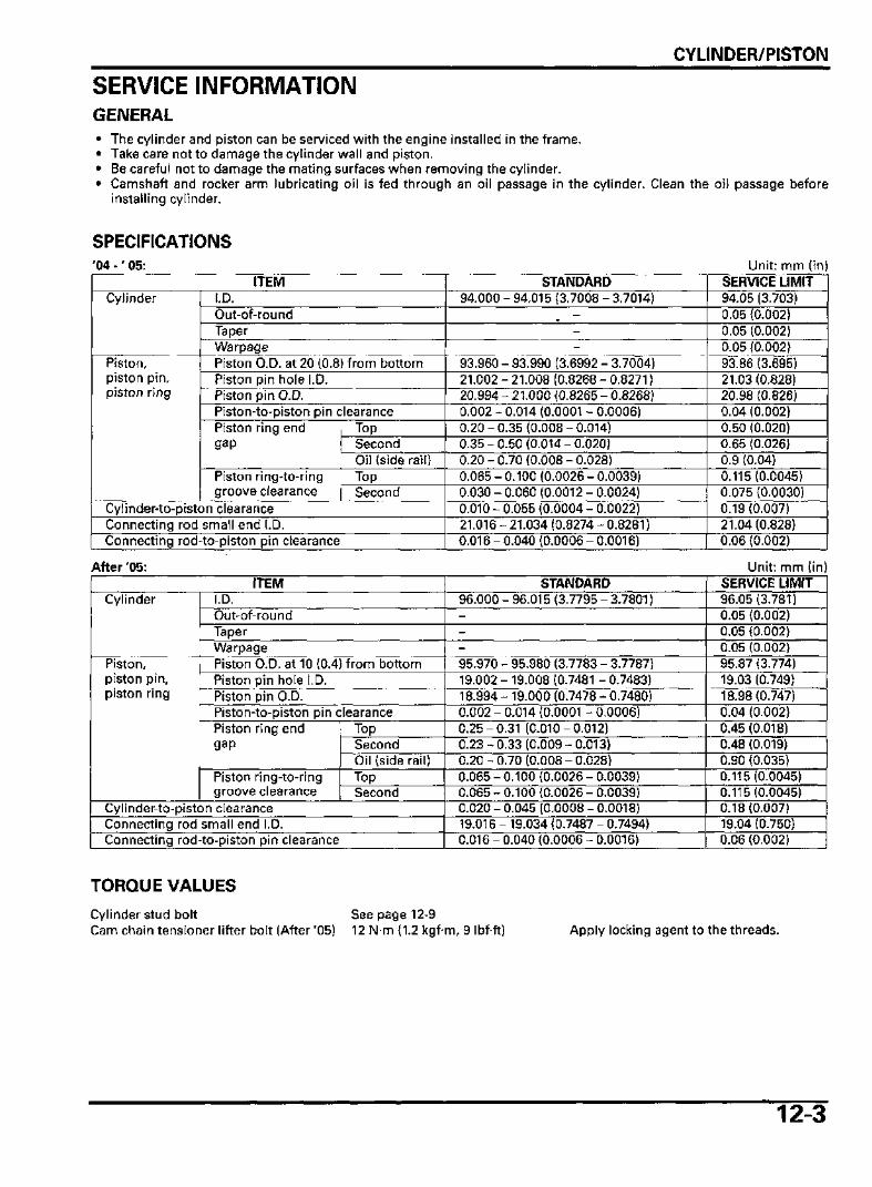
SERVICE INFORMATIONGENERAL• The cylinder and piston can be serviced with the engine installed in the frame.• Take care not to damage the cylinder wall and piston.• Be careful not to damage the mating surfaces when removing the cylinder.• Camshaft and rocker arm lubricating oil is fed through an oil passage in the cylinder. Clean the oil passage before
installing cylinder.
SPECIFICATIONS'04 - ' 05:
ITEMCylinder
Piston,piston pin,piston ring
I.D.Out-of-roundTaperWarpagePiston O.D. at 20 (0.8) from bottomPiston pin hole I.D.Piston pin O.D.Piston-to-piston pin clearancePiston ring endgap
Piston ring-to-ringgroove clearance
TopSecondOil (side rail)TopSecond
Cylinder-to-piston clearanceConnecting rod small end I.D.Connecting rod-to-piston pin clearance
STANDARD94.000 - 94.015 (3.7008 - 3.7014)
---
93.960 - 93.990 (3.6992 - 3.7004)21.002 - 21.008 (0.8268 - 0.8271)20.994 - 21.000 (0.8265 - 0.8268)0.002 - 0.014 (0.0001 - 0.0006)0.20-0.35(0.008-0.014)0.35-0.50(0.014-0.020)0.20-0.70(0.008-0.028)0.065 - 0.100 (0.0026 - 0.0039)0.030 - 0.060 (0.0012 - 0.0024)0.010 - 0.055 (0.0004 - 0.0022)21.016 - 21.034 (0.8274 - 0.8281)0.016 - 0.040 (0.0006 - 0.0016)
Unit: mm (in)SERVICE LIMIT94.05 (3.703)0.05 (0.002)0.05 (0.002)0.05 (0.002)93.86 (3.695)21.03 (0.828)20.98 (0.826)0.04 (0.002)0.50 (0.020)0.65 (0.026)0.9 (0.04)0.115(0.0045)0.075 (0.0030)0.19(0.007)21.04 (0.828)0.06 (0.002)
After '05:ITEM
Cylinder
Piston,piston pin,piston ring
I.D.Out-of-roundTaperWarpagePiston O.D. at 10 (0.4) from bottomPiston pin hole I.D.Piston pin O.D.Piston-to-piston pin clearancePiston ring endgap
Piston ring-to-ringgroove clearance
TopSecondOil (side rail)TopSecond
Cylinder-to-piston clearanceConnecting rod small end I.D.Connecting rod-to-piston pin clearance
STANDARD96.000 - 96.015 (3.7795 - 3.7801)---95.970 - 95.980 (3.7783 - 3.7787)19.002 - 19.008 (0.7481 - 0.7483)18.994 - 19.000 (0.7478 - 0.7480)0.002 - 0.014 (0.0001 - 0.0006)0.25-0.31 (0.010-0.012)0.23-0.33(0.009-0.013)0.20-0.70(0.008-0.028)0.065 - 0.100 (0.0026 - 0.0039)0.065 - 0.100 (0.0026 - 0.0039)0.020 - 0.045 (0.0008 - 0.0018)19.016 - 19.034 (0.7487 - 0.7494)0.016 - 0.040 (0.0006 - 0.0016)
Unit: mm (in)SERVICE LIMIT96.05(3.781)0.05 (0.002)0.05 (0.002)0.05 (0.002)95.87 (3.774)19.03 (0.749)18.98(0.747)0.04 (0.002)0.45 (0.018)0.48 (0.019)0.90 (0.035)0.115(0.0045)0.115(0.0045)0.18(0.007)19.04 (0.750)0.06 (0.002)
TORQUE VALUES
Cylinder stud boltCam chain tensioner lifter bolt (After '05)
See page 12-912N-m(1.2kgfm, 9 Ibfft) Apply locking agent to the threads.
12-3
CYLINDER/PISTON
TROUBLESHOOTINGCompression too low, hard starting or poor performance at low speed• Leaking cylinder head gasket• Worn, stuck or broken piston ring• Worn or damaged cylinder and piston
Compression too high, overheating or knocking• Excessive carbon built-up on piston head or combustion chamber
Excessive smoke• Worn cylinder, piston or piston rings• Improper installation of piston rings• Scored or scratched piston or cylinder wall
Abnormal noise• Worn piston pin or piston pin hole• Worn connecting rod small end• Worn cylinder, piston or piston rings
12-4

CYLINDER/PISTON
CYLINDER/PISTON REMOVALCYLINDER REMOVALRemove the cylinder head (page 11-15).
Remove the following:- bolt- cylinder (being careful not to damage the piston
with the stud bolts)
- joint collar- dowel pins- gasket
'04 - '05: - two bolts- cam chain tensioner lifter- gasket
After '05: - two bolts- cam chain tensioner lifter- gaskets- lifter base
LIFTER BASE
iGASKETS
12-5

CYLINDER/PISTONAfter '05: Disconnect the breather hose from cylinder.
Place a clean shoptowel over the
crankcase toprevent the clip
from falling into thecrankcase.
Do not damage thepiston rings by
spreading the endstoo far.
BREATHER HOSE
PISTON REMOVALRemove the piston pin clip with pliers.
Push the piston pin out of the piston and connectingrod, and remove the piston.
I / PISTON PIN ,
Vk
\ CLIP '
PISTON/ / s
V
Spread each piston ring and remove it by lifting upat a point opposite the gap.
Never use a wire Clean carbon deposits from the piston ring groovesbrush; it will scratch with a ring that will be discarded.
the groove.
12-6
CYLINDER/PISTON
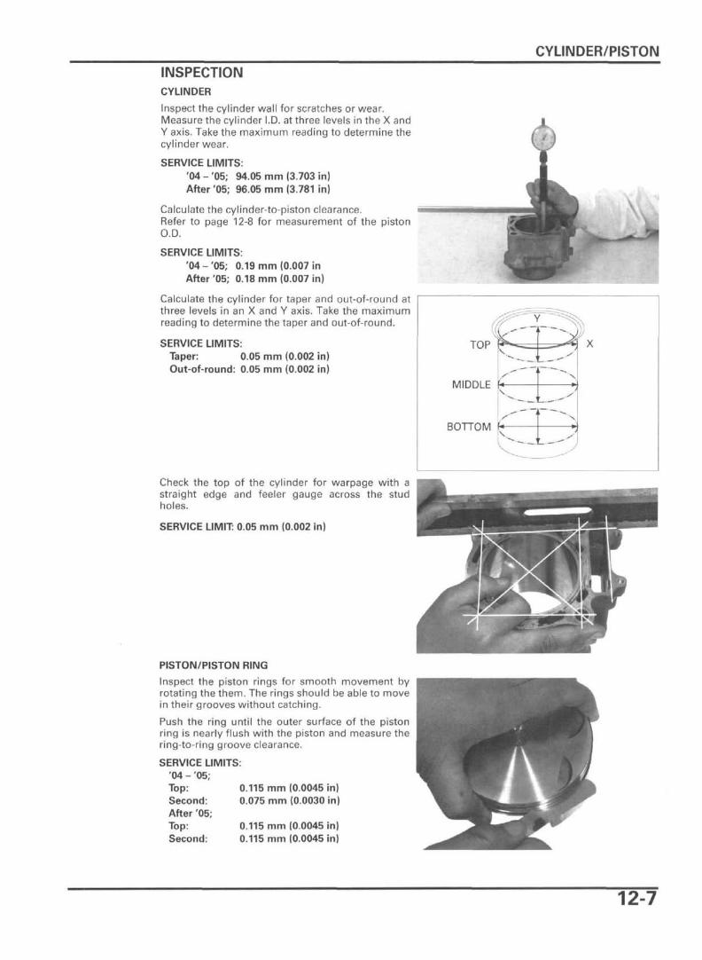
INSPECTIONCYLINDER
Inspect the cylinder wall for scratches or wear.Measure the cylinder I.D. at three levels in the X andY axis. Take the maximum reading to determine thecylinder wear.
SERVICE LIMITS:'04 - '05; 94.05 mm (3.703 in)After '05; 96.05 mm (3.781 in)
Calculate the cylinder-to-piston clearance.Refer to page 12-8 for measurement of the pistonO.D.
SERVICE LIMITS:'04-'05; 0.19 mm (0.007 inAfter '05; 0.18 mm (0.007 in)
Calculate the cylinder for taper and out-of-round atthree levels in an X and Y axis. Take the maximumreading to determine the taper and out-of-round.
SERVICE LIMITS:Taper: 0.05 mm (0.002 in)Out-of-round: 0.05 mm (0.002 in)
TOP
MIDDLE
BOTTOM
v.
V !
^5y
X
Check the top of the cylinder for warpage with astraight edge and feeler gauge across the studholes.
SERVICE LIMIT: 0.05 mm (0.002 in)
PISTON/PISTON RING
Inspect the piston rings for smooth movement byrotating the them. The rings should be able to movein their grooves without catching.
Push the ring until the outer surface of the pistonring is nearly flush with the piston and measure thering-to-ring groove clearance.
SERVICE LIMITS:'04 - '05;Top:Second:After 05;Top:Second:
0.115 mm (0.0045 in)0.075 mm (0.0030 in)
0.115 mm (0.0045 in)0.115 mm (0.0045 in)
12-7
CYLINDER/PISTON
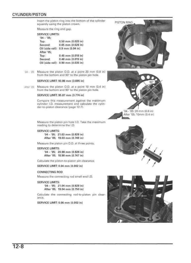
Insert the piston ring into the bottom of the cylindersquarely using the piston crown.
Measure the ring end gap.
SERVICE LIMITS:'04 - '05;Top: 0.50 mm (0.020 in)Second: 0.65 mm (0.026 in)Oil (side rail): 0.9 mm (0.04 in)After '05;Top: 0.45 mm (0.018 in)Second: 0.48 mm (0.019 in)Oil (side rail): 0.90 mm (0.035 in)
'04- '05: Measure the piston O.D. at a point 20 mm (0.8 in)from the bottom and 90° to the piston pin hole.
SERVICE LIMIT: 93.86 mm (3.695 in)
After '05: Measure the piston O.D. at a point 10 mm (0.4 in)from the bottom and 90° to the piston pin hole.
SERVICE LIMIT: 95.87 mm (3.774 in)
Compare this measurement against the maximumcylinder I.D. measurement and calculate the cylin-der-to-piston clearance (page 12-7).
Measure the piston pin hole I.D. Take the maximumreading to determine the I.D.
SERVICE LIMITS:'04 - '05; 21.03 mm (0.828 in)After '05; 19.03 mm (0.749 in)
Measure the piston pin O.D. at three points.
SERVICE LIMITS:'04 - '05; 20.98 mm (0.826 in)After '05; 18.98 mm (0.747 in)
Calculate the piston-to-piston pin clearance.
SERVICE LIMIT: 0.04 mm (0.002 in)
CONNECTING ROD
Measure the connecting rod small end I.D.
SERVICE LIMITS:'04-'05; 21.04 mm (0.828 in)After '05; 19.04 mm (0.750 in)
Calculate the connecting rod-to-piston pin clear-ance.
SERVICE LIMIT: 0.06 mm (0.002 in)
PISTON RING
'04-'05: 20 mm (0.8 in)After'05:10mm (0.4 in)
12-8
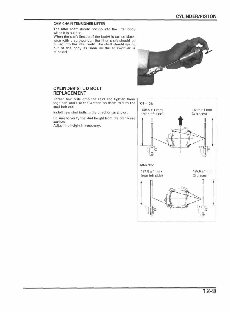
CYLINDER/PISTONCAM CHAIN TENSIONER LIFTER
The lifter shaft should not go into the lifter bodywhen it is pushed.When the shaft (inside of the body) is turned clock-wise with a screwdriver, the lifter shaft should bepulled into the lifter body. The shaft should springout of the body as soon as the screwdriver isreleased.
CYLINDER STUD BOLTREPLACEMENTThread two nuts onto the stud and tighten themtogether, and use the wrench on them to turn thestud bolt out.
Install new stud bolts in the direction as shown.
Be sure to verify the stud height from the crankcasesurface.Adjust the height if necessary.
'04 - '05:
145.5 ± 1 mm(rear left side)
149.5±1 mm(3 places)
After '05:
134.5 ± 1 mm(rear left side)
138.511 mm(3 places)
12-9

CYLINDER/PISTON
CYLINDER/PISTON INSTALLATIONPISTON RING INSTALLATIONCarefully install the piston rings into the piston ringgrooves with the marks facing up.
NOTE:• Do not confuse the top and second rings.• To install the oil ring, install the spacer first, then
install the side rails.
Stagger the piston ring end gaps 120° apart fromeach other.Stagger the side rail end gaps as shown.
MARK
SIDE RAILS
SPACER
TOP RING
SECOND RING
OIL RING
20 mm or more
PISTON INSTALLATIONPlace a clean shop towel over the crankcase to pre-vent the piston pin clip from falling into the crank-case.
Apply molybdenum oil solution to the connectingrod small end inner surface and piston pin outersurface.
12-10
CYLINDER/PISTON
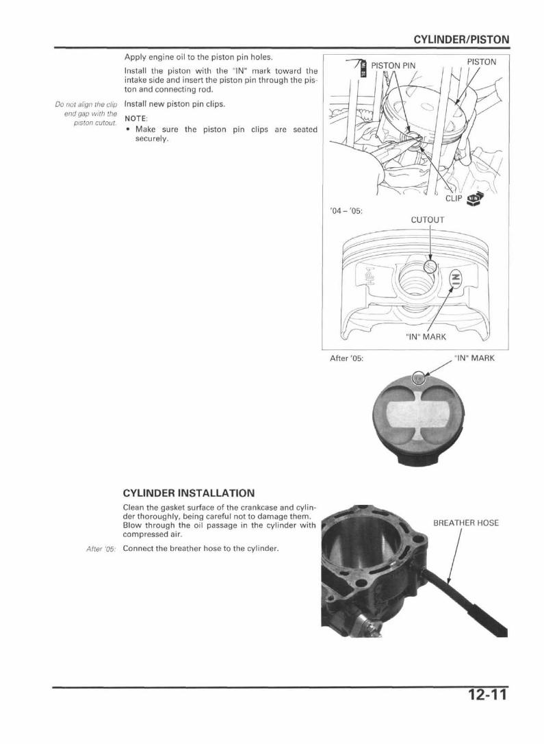
Apply engine oil to the piston pin holes.
Install the piston with the "IN" mark toward theintake side and insert the piston pin through the pis-ton and connecting rod.
Do not align the clip Install new piston pin clips.end gap with the N r . T F
piston cutout. N O T E
• Make sure the piston pin clips are seatedsecurely.
PISTON PIN PISTON
'04- '05:CUTOUT
After '05: "IN" MARK
CYLINDER INSTALLATIONClean the gasket surface of the crankcase and cylin-der thoroughly, being careful not to damage them.Blow through the oil passage in the cylinder withcompressed air.
After '05: Connect the breather hose to the cylinder.
BREATHER HOSE
12-11
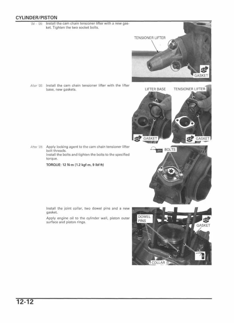
CYLINDER/PISTON'04 - '05: Install the cam chain tensioner lifter with a new gas-
ket. Tighten the two socket bolts.
TENSIONER LIFTER
After '05: Install the cam chain tensioner lifter with the lifterbase, new gaskets. LIFTER BASE TENSIONER LIFTER
After '05: Apply locking agent to the cam chain tensioner lifterbolt threads.Install the bolts and tighten the bolts to the specifiedtorque.
TORQUE: 12 N m (1.2 kgf m, 9 Ibf-ft)
Install the joint collar, two dowel pins and a newgasket.
Apply engine oil to the cylinder wall, piston outersurface and piston rings.
12-12

CYLINDER/PISTON
Route the cam chain through the cylinder and install Ithe cylinder over the piston while compressing the *piston rings with your fingers. CHAIN
Tighten the cylinderbolt after installingthe cylinder head.
Make sure that the cylinder touches the crankcaseevenly. Install the cylinder bolt.
Install the cylinder head (page 11-24).
12-13