system architecture for variable message...
TRANSCRIPT

System Architecture for Variable Message Signs
Hannes Kulovitsswarco Futurit Ges.m.b.H.
Software DevelopmentZichygasse 8
A-1140 [email protected]
Christoph Stogererswarco Futurit Ges.m.b.H.
Software DevelopmentZichygasse 8
A-1140 [email protected]
Wolfgang KastnerTU Vienna
Institute of AutomationTreitlstrasse 1
A-1040 [email protected]
Abstract
Traffic control and information systems are used inmodern traffic technology for information propagationfrom a higher order control unit to the traffic participant.In up to date systems, the user interface for the trafficparticipant is provided via programmable signs display-ing traffic jam warnings, speed limits or route diversion.These signs can be switched on or off and fed with arbi-trary data corresponding to the present traffic situation.However, signs are manifold in size, functionality andmeans to communicate with them. This paper proposesa component based software architecture that allows arapid integration of such (and future) signs into existingtraffic management systems.
1. Introduction
Traffic signaling has its roots in the late 1970s whenfiber optic signs for speed limit signalization appeared. Atthat time, traffic signs based on dot matrices were mainlyaccessed on-site via specialized hardware and digital I/Oand were able to display different, but fixed signalizationpictograms (Figure 1).
Figure 1. Traffic sign dot matrix
Soon, first simple serial communication protocols su-perseded digital I/O lines and offered to better fulfill up-coming demands for monitoring the sign facilities (e. g.the light source).
With the advent of light emitting diodes (LEDs) en-abling rising performance regarding light output, reduc-tion of power consumption and higher lifetime in con-trast to the light sources used in the fiber optic tech-nology, sign manufacturers changed over using LED-technology for signaling issues. At the beginning thesediodes were mainly found in the advertising domainwhere monochrome LED-screens and later on full colortechnology composing pixels of three LEDs in red, greenand blue (RGB) color were used. Shortly after, the con-cept was taken over to the traffic domain as well.
Starting from relatively simple traffic signs (e. g. againfor speed limit signalization) with a limited number ofdepictable pictures (“limited signs”), applications weregetting more complex. So called “programmable trafficsigns” were coming up, providing the possibility to dis-play text and pictures that are not predefined (Figure 2).
Figure 2. Programmable traffic sign
Since then signs for the purpose of displaying one of anumber of legends that may be changed or switched off asrequired, were named Variable Message Signs in the con-text of road applications [13]. Besides Variable MessageSigns (VMS), Dynamic Route Information Panels (DRIP)as outlined by Schouten et.al. [11] or Graphical Route In-formation Panels (GRIP) as presented by Alkim et.al. [2]were introduced.
Subsequently, different combinations and variations oflimited and programmable traffic signs emerged with in-creasing complexity and demands for safety issues (re-liability, dependability). For instance, the requirementschanged from initially more or less simple monitoringof the light source to consistently supervising electronic
0-7803-9402-X/05/$20.00 © 2005 IEEE
Traffic Management andInformation Center
* data processing* data collection* video monitoring* global control
Sub-Station
A
* data processing* error detection* traffic situation reporting* autonomous control
B
* data processing* error detection* traffic situation reporting* manual control* on-site control
A 1
Local Control Unit(Outstation)
E 12
B
Sub-Station
Control module
I/O-Converter
I/O-Converter...
E
D
VMSDetector Detector VMS
Local Control Unit(Outstation)
C
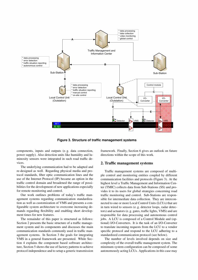
Figure 3. Structure of traffic management systems
components, inputs and outputs (e. g. data connection,power supply). Also detection units like humidity and lu-minosity sensors were integrated in such road traffic de-vices.
The underlying communication had to be adapted andre-designed as well. Regarding physical media and pro-tocol standards, fiber optic communication lines and theuse of the Internet Protocol (IP) became an option in thetraffic control domain and broadened the range of possi-bilities for the development of new applications especiallyfor remote monitoring and control.
Our work outlines problems of today’s traffic man-agement systems regarding communication standardiza-tion as well as customization of VMS and presents a con-figurable system architecture to overcome increasing de-mands regarding flexibility and enabling short develop-ment times for new features.
The remainder of this paper is structured as follows:Section 2 presents the basic structure of a traffic manage-ment system and its components and discusses the maincommunication standards commonly used in traffic man-agement systems. In Section 3 the goals for integratingVMS in a general framework are presented. While Sec-tion 4 explains the component based software architec-ture, Section 5 shows the use of factory patterns to achieveprotocol independence and to setup a generic transmission
framework. Finally, Section 6 gives an outlook on futuredirections within the scope of this work.
2. Traffic management systems
Traffic management systems are composed of multi-ple control and monitoring entities coupled by differentcommunication facilities and protocols (Figure 3). At thehighest level a Traffic Management and Information Cen-ter (TMIC) collects data from Sub-Stations (SS) and pro-vides it to its users for global strategies concerning roadtraffic monitoring and control. Sub-Stations are respon-sible for intermediate data collection. They are intercon-nected to one or more Local Control Units (LCUs) that arein turn wired to sensors (e. g. detector loops, radar detec-tors) and actuators (e. g. gates, traffic lights, VMS) and areresponsible for data processing and autonomous controljobs. A LCU is composed of a Control Module and (op-tional) I/O-Converters. It is the task of an I/O-Converterto translate incoming requests from the LCU to a vendorspecific protocol and respond to the LCU adhering to astandardized communication protocol (see below).
The number of levels involved depends on size andcomplexity of the overall traffic management system. Theminimum system configuration can be composed of someautonomously acting LCUs. Applications in this case may
care for the visualization of successive speed reductionfor a specific section of road. This could be handled forinstance via three VMS with 500 m in between display-ing 130 km/h, 100 km/h and 80 km/h, respectively. Themaximum system configuration consists of multiple lev-els of control and monitoring facilities, where each levelis designed for autonomous operation as a kind of fall-back in case of breakdown of a higher order level facility.Applications in this case include sophisticated traffic jamcollision detection mechanisms and control of VMS withinstructions for rerouting.
Throughout the hierarchical structure, communicationfacilities differ in requirements depending on the levels in-volved. After several pilot projects were started, some re-gional restricted (de-facto) standards regarding communi-cation protocols and facilities were introduced. The mostimportant ones are listed in Table 1.
Table 1. Communication standards in thetraffic domain: overview
Communication standard Country of originTLS [5] Germany
TLS over IP [4] AustriaDAP [14] NetherlandsNTCIP [1] US
Up to now, these communication standards are dedi-cated to specific communication levels of a traffic man-agement system structure. Thus, one single standard can-not be applied to a fully deployed traffic management sys-tem, i. e. from its highest level A to its lowest levels Dor E (cf. Figure 3). Table 2 shows for each mentionedprotocol its position and the devices included.
Table 2. Communication standards in thetraffic domain: levels and devices involved
Communication Data exchangestandard Levels between
device deviceTLS over IP A TMIC SSTLS over IP B SS LCU
TLS B SS LCUTLS C SS I/O-Conv.
TMIC orDAP (A− C) SS or End device
LCUTMIC or
NTCIP (A− C) SS or End deviceTMIC
3. Goals
The remainder of this paper focuses on the communi-cation between end devices, especially VMS, and – de-
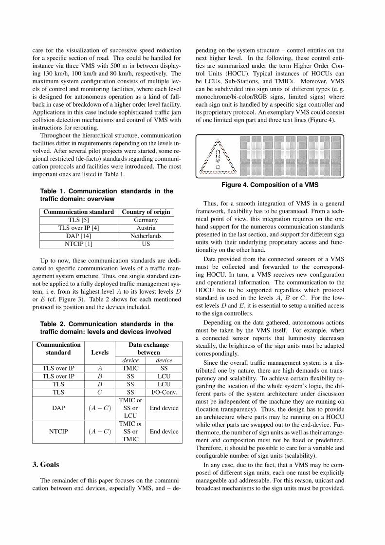
pending on the system structure – control entities on thenext higher level. In the following, these control enti-ties are summarized under the term Higher Order Con-trol Units (HOCU). Typical instances of HOCUs canbe LCUs, Sub-Stations, and TMICs. Moreover, VMScan be subdivided into sign units of different types (e. g.monochrome/bi-color/RGB signs, limited signs) whereeach sign unit is handled by a specific sign controller andits proprietary protocol. An exemplary VMS could consistof one limited sign part and three text lines (Figure 4).
Figure 4. Composition of a VMS
Thus, for a smooth integration of VMS in a generalframework, flexibility has to be guaranteed. From a tech-nical point of view, this integration requires on the onehand support for the numerous communication standardspresented in the last section, and support for different signunits with their underlying proprietary access and func-tionality on the other hand.
Data provided from the connected sensors of a VMSmust be collected and forwarded to the correspond-ing HOCU. In turn, a VMS receives new configurationand operational information. The communication to theHOCU has to be supported regardless which protocolstandard is used in the levels A, B or C. For the low-est levels D and E, it is essential to setup a unified accessto the sign controllers.
Depending on the data gathered, autonomous actionsmust be taken by the VMS itself. For example, whena connected sensor reports that luminosity decreasessteadily, the brightness of the sign units must be adaptedcorrespondingly.
Since the overall traffic management system is a dis-tributed one by nature, there are high demands on trans-parency and scalability. To achieve certain flexibility re-garding the location of the whole system’s logic, the dif-ferent parts of the system architecture under discussionmust be independent of the machine they are running on(location transparency). Thus, the design has to providean architecture where parts may be running on a HOCUwhile other parts are swapped out to the end-device. Fur-thermore, the number of sign units as well as their arrange-ment and composition must not be fixed or predefined.Therefore, it should be possible to care for a variable andconfigurable number of sign units (scalability).
In any case, due to the fact, that a VMS may be com-posed of different sign units, each one must be explicitlymanageable and addressable. For this reason, unicast andbroadcast mechanisms to the sign units must be provided.

Specific protocol Communicator
Request action viastandardized
interface
Controller
Request action viastandardized
interface
PLC Service
FuturitCom protocol
Response to requestvia standardizedinterface (connectionpoint)
Third PartyPLC System
Response to requestvia standardizedinterface (connectionpoint)
Control UnitHigher Order
HardwareController Sign
Figure 5. Communication interface schema
4. Software architecture
From an economic point of view, the developmentcosts (especially for future extensions) have to be kept aslow as possible. In addition, the ability to react to newmarkets needs (e. g. integration of protocols for commu-nication with HOCUs) has to be done as fast as possible.Therefore our approach is to integrate the I/O-Converter’sfunctionality as part of the LCU using component tech-nology with the goal of shortening reaction times whenadopting different protocols in a configurable and flexibleway.
The following higher order requirements had to be met:
• The solution had to be designed in a highly flexible,adaptable and distributed way.
• The coupling of the components had to be held aslow as possible to ease software updates (integrationof further protocols) and minimize error propagation.
• The solution had to provide a high degree of stabilityand reliability. Therefore it is necessary to executethe software in some kind of system mode and startrunning it automatically after computer restart with-out user actions being taken.
• Most notably, the solution had to be based on a MS-Windows embedded operating system.
To meet the main requirements the following technol-ogy decisions were taken:
• The Rational Unified Process [9] was used as thesoftware life cycle, due to the fact that this approachallows for an architecture-centric development pro-cess.
• To provide a range of services for component interac-tion, from services promoting component integrationon a single platform, to component interaction acrossheterogeneous networks, COM/DCOM [7] was cho-sen.
• As the components must be able to (1) run in thebackground of the system, (2) start automatically incase of a system reboot, (3) execute without user lo-gin, the decision was taken to use MS-Windows Ser-vices.
Finally, the software architecture was divided into threeindependent and self-contained components, namely PLCService, Communicator and Controller discussed in moredetail in the remainder of this section (Figure 5).
4.1. PLC ServiceThe PLC Service is responsible for interfacing with the
underlying hardware (in our case this is a third party PLCsystem) and provides an (abstract) interface to it. Thus,components that use the PLC Service are completely hard-ware independent. Consequently, whenever the PLC sys-tem is to be replaced, the only part of the software archi-tecture that has to be adapted is the PLC Service.

Moreover, the PLC Service cares for a publisher-subscriber mechanism. It provides notifications for inter-ested subscribers each time a modification of the processdata occurs. Such interesting events can be for instancethe change of luminosity or the change of temperature.
Via the PLC Service it is possible to define for interest-ing parts of the process data (so-called I/O points) a nameand description, a corresponding unit, a factor for scalingpurpose, a range for the scaled value, as well as a time slot.In case of an updated value that is stable within the spec-ified time slot, the component provides it to subscribersvia a dedicated connection point. Each I/O point is con-figurable regarding its address, where its current valuescan be derived from. In addition, the PLC Service allowsconfiguration issues supporting to categorize and store theconnected I/O points in groups called I/O-Categories.
The benefit of the PLC Service lies in this configura-bility which enables a customization of the whole systemwithout changing the PLC Service application itself. Thesetup process consists of two important phases. The firstone copes with the creation of the appropriate PLC pro-gram in the underlying PLC application the PLC Serviceis connected to. The second one tackles the connection tothe underlying PLC application (i. e. communication facil-ities) and logging issues by configuring the system usingan XML configuration file.
4.2. ControllerThe Controller component has to manage the commu-
nication to a configurable quantity of different sign con-trollers belonging to one or more physical VMS. Thus,the most important task of the Controller is to provide auniform interface for communicating with them. This in-terface is bundled into the so-called FuturitCom protocol(Figure 6).
Signcontroller 1
Signcontroller 2
Signcontroller n
Hardwarespecific
protocol 1
Hardwarespecific
protocol 2
...
Hardwarespecific
protocol n
FuturitComprotocol
Figure 6. FuturitCom protocol
The communication to sign controllers can be handledeither via a serial connection or via UDP/IP. To make each
sign controller as well as the whole VMS addressable,the sign units and their corresponding Controller need aunique address. For this reason, the address structure x.ywas introduced where x stands for the address of the Con-troller and y for the address of a sign unit. To operate allsign units at once in the custody of a specific Controllerthe sub-address is set to zero.
The component offers the full command language setof the FuturitCom protocol via the IFuturitCom in-terface. The interface includes functions like Poll()which is used to determine the status of the sign,SetBrightness(), for setting the current luminos-ity of the sign, or SetContent() to upload a specificcontent (e. g. a bitmap). Following the address scheme,each method needs the address of the Controller and thesub-address of the sign unit to uniquely identify the cor-responding part of the sign. As a result the Controllercomponent enables an absolute transparent, uniform andcoherent way of controlling and monitoring the sign con-nected to the system.
Furthermore, the component cares for an event inter-face, called IFuturitComEvents, which must be im-plemented by each user of the Controller component.This interface contains a counterpart for each method con-tained in the IFuturitCom interface. A method of theIFuturitComEvents interface is activated whenevera response of a call to the corresponding IFuturitCommethod is ready. For instance, to determine the status ofa sign, the Poll() command must be used. After theController processed the command, it notifies the callerby invoking the corresponding OnPoll() method of theIFuturitComEvents interface.
Last but not least, the Controller is responsible for au-tonomous control. Therefore, it reacts to data receivedfrom the PLC Service, such as controlling the brightnessof a VMS autonomously. For this reason, it can subscribeto the events provided by the PLC Service.
The configuration of the Controller is divided up intotwo parts: The first part deals with the communication,i. e. what kind of communication (serial or UDP/IP) shallbe used, and which sign units are driven by the Con-troller. The second part covers issues for autonomouscontrol (e. g. automatically dimming the sign) and safetyrelevant features (e. g. cyclic testing of LED-displays).
4.3. CommunicatorFigure 3 outlined that a VMS is integrated into a traf-
fic management system where different units are involved.As mentioned at the beginning of this section, one impor-tant requirement is to cut down on the need to use an I/O-Converter to enable the communication with the VMS.However, without an I/O-Converter the VMS has to han-dle the different communication standards on its own (cf.Table 2). Thus, the HOCU directly connects to the VMSin order to control it via varying commands.
The interface to the HOCU is provided by the Commu-nicator component. The main challenge of the Communi-

cator is to perform the following tasks independently ofthe protocol used (e. g. FuturitCom, TLS, SiTOS [12]):
• wait for an incoming request from a HOCU.
• validate the request, i. e. send a positive acknowledg-ment, if it is correct, return a negative acknowledg-ment, if the request is invalid, or ignore the requestin all other cases.
• delegate the request to the Controller componentwhich communicates with the underlying VMS andits sign units.
• wait for a response from the Controller component.
• return the response to the HOCU.
5. Communication based on factory patterns
The whole system must be configurable in a waythat allows to choose between different command lan-guage sets before run-time. This requirement especiallybothers the Communicator, for it has to react to com-mands requested by the HOCU. To solve this problemtwo abstract classes were defined. The first one, namedGenericTelegram, forms the base class for the dif-ferent telegrams of the supported command languagesets. It provides an interface for retrieving the telegrambyte stream and its length. The second class, calledTransmission, offers an interface for establishing andclosing a connection, and transmitting telegrams. It actsas base class for the different supported forms of commu-nication mechanisms (serial and UDP/IP).
+GetTelegramStream()+GetTelegramLength()
GenericTelegram
FuturitComTelegram TLSTelegram
+CreateTelegram()ITelegramFactory
+CreateTelegram()FuturitComTelegramFactory
+CreateTelegram()TLSTelegramFactory
Figure 7. Telegram factory
These two classes build the essential components ofa transmission framework used to send and receive tele-grams. Both, the Controller and Communicator use the
transmission framework as an integral part of their func-tionality. The Controller utilizes the framework to com-municate with its connected sign controllers and the Com-municator needs it to interact with the HOCU.
The main functionality of the transmission framework(send and receive commands) seems not to be a thrillingjob and suggests that there should be ready-to-use so-lutions (i. e. libraries) available. However, in our casetwo requirements make it a very special task and, as faras we know, unique: transmitting of commands mustbe performed in a very generic way in terms of (1) theused command language set and (2) the desired commu-nication mechanisms. To solve this problem we proposea design where the transmission framework rests uponthe abstract classes GenericTelegram (Figure 7) andTransmission (Figure 8), only. In addition, for bothclasses the Abstract Factory Pattern [6] is chosen. Thisdecision enables a very flexible design that can be easilyadapted in two directions: the first one is related to the de-sired way of communication and the second one opens fa-cilities to rapidly react to upcoming command languages.Forthcoming extensions have never to touch the transmis-sion framework regardless whether an additional way ofcommunication (e. g. TCP/IP) or a further command lan-guage set (e. g. NTCIP) has to be implemented.
+Send()#EstablishConnection()#CloseConnection()
UDPTransmission+Send()#EstablishConnection()#CloseConnection()
SerialTransmission
+CreateTransmission()TransmissionFactory
+CreateTransmission()SerialTransmissionFactory
+CreateTransmission()UDPTransmissionFactory
GenericTelegram#EstablishConnection()#CloseConnection()+Initialize()+UnInitialize()+Send()
Transmission
Figure 8. Transmission factory
By means of the method CreateTelegram(), atelegram of the configured protocol (e. g. TLS) can be cre-ated from a given byte stream, which will be provided viaa parameter. The method throws an exception in case thetelegram is not valid, i. e. if it does not correspond to thecommand language set (e. g. FuturitCom) or is syntacti-cally incorrect. If the telegram is valid, it returns an ob-ject of the created telegram represented by its superclassGenericTelegram.
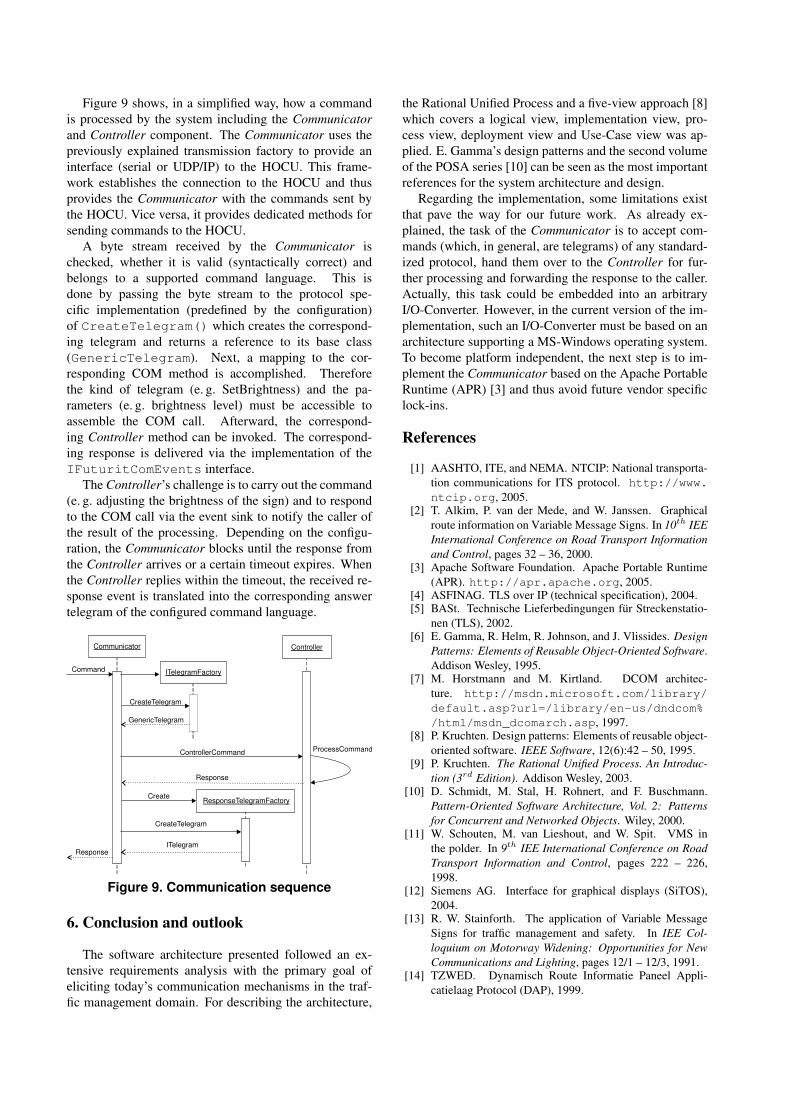
Figure 9 shows, in a simplified way, how a commandis processed by the system including the Communicatorand Controller component. The Communicator uses thepreviously explained transmission factory to provide aninterface (serial or UDP/IP) to the HOCU. This frame-work establishes the connection to the HOCU and thusprovides the Communicator with the commands sent bythe HOCU. Vice versa, it provides dedicated methods forsending commands to the HOCU.
A byte stream received by the Communicator ischecked, whether it is valid (syntactically correct) andbelongs to a supported command language. This isdone by passing the byte stream to the protocol spe-cific implementation (predefined by the configuration)of CreateTelegram() which creates the correspond-ing telegram and returns a reference to its base class(GenericTelegram). Next, a mapping to the cor-responding COM method is accomplished. Thereforethe kind of telegram (e. g. SetBrightness) and the pa-rameters (e. g. brightness level) must be accessible toassemble the COM call. Afterward, the correspond-ing Controller method can be invoked. The correspond-ing response is delivered via the implementation of theIFuturitComEvents interface.
The Controller’s challenge is to carry out the command(e. g. adjusting the brightness of the sign) and to respondto the COM call via the event sink to notify the caller ofthe result of the processing. Depending on the configu-ration, the Communicator blocks until the response fromthe Controller arrives or a certain timeout expires. Whenthe Controller replies within the timeout, the received re-sponse event is translated into the corresponding answertelegram of the configured command language.
Command
Communicator
ITelegramFactory
Controller
ControllerCommand
Response
ResponseTelegramFactoryCreate
CreateTelegram
ITelegramResponse
ProcessCommand
CreateTelegram
GenericTelegram
Figure 9. Communication sequence
6. Conclusion and outlook
The software architecture presented followed an ex-tensive requirements analysis with the primary goal ofeliciting today’s communication mechanisms in the traf-fic management domain. For describing the architecture,
the Rational Unified Process and a five-view approach [8]which covers a logical view, implementation view, pro-cess view, deployment view and Use-Case view was ap-plied. E. Gamma’s design patterns and the second volumeof the POSA series [10] can be seen as the most importantreferences for the system architecture and design.
Regarding the implementation, some limitations existthat pave the way for our future work. As already ex-plained, the task of the Communicator is to accept com-mands (which, in general, are telegrams) of any standard-ized protocol, hand them over to the Controller for fur-ther processing and forwarding the response to the caller.Actually, this task could be embedded into an arbitraryI/O-Converter. However, in the current version of the im-plementation, such an I/O-Converter must be based on anarchitecture supporting a MS-Windows operating system.To become platform independent, the next step is to im-plement the Communicator based on the Apache PortableRuntime (APR) [3] and thus avoid future vendor specificlock-ins.
References
[1] AASHTO, ITE, and NEMA. NTCIP: National transporta-tion communications for ITS protocol. http://www.ntcip.org, 2005.
[2] T. Alkim, P. van der Mede, and W. Janssen. Graphicalroute information on Variable Message Signs. In 10th IEEInternational Conference on Road Transport Informationand Control, pages 32 – 36, 2000.
[3] Apache Software Foundation. Apache Portable Runtime(APR). http://apr.apache.org, 2005.
[4] ASFINAG. TLS over IP (technical specification), 2004.[5] BASt. Technische Lieferbedingungen fur Streckenstatio-
nen (TLS), 2002.[6] E. Gamma, R. Helm, R. Johnson, and J. Vlissides. Design
Patterns: Elements of Reusable Object-Oriented Software.Addison Wesley, 1995.
[7] M. Horstmann and M. Kirtland. DCOM architec-ture. http://msdn.microsoft.com/library/default.asp?url=/library/en-us/dndcom%/html/msdn_dcomarch.asp, 1997.
[8] P. Kruchten. Design patterns: Elements of reusable object-oriented software. IEEE Software, 12(6):42 – 50, 1995.
[9] P. Kruchten. The Rational Unified Process. An Introduc-tion (3rd Edition). Addison Wesley, 2003.
[10] D. Schmidt, M. Stal, H. Rohnert, and F. Buschmann.Pattern-Oriented Software Architecture, Vol. 2: Patternsfor Concurrent and Networked Objects. Wiley, 2000.
[11] W. Schouten, M. van Lieshout, and W. Spit. VMS inthe polder. In 9th IEE International Conference on RoadTransport Information and Control, pages 222 – 226,1998.
[12] Siemens AG. Interface for graphical displays (SiTOS),2004.
[13] R. W. Stainforth. The application of Variable MessageSigns for traffic management and safety. In IEE Col-loquium on Motorway Widening: Opportunities for NewCommunications and Lighting, pages 12/1 – 12/3, 1991.
[14] TZWED. Dynamisch Route Informatie Paneel Appli-catielaag Protocol (DAP), 1999.
