sysmac library - assets.omron.eu · sysmac library high speed analog test library user's...
TRANSCRIPT

Sysmac Library
High Speed Analog Test Library
User's Manual
SYSMAC-XR016
W607-E1-01

NOTE
(1) All rights reserved. No part of this publication may be reproduced, stored in a retrieval system, ortransmitted, in any form, or by any means, mechanical, electronic, photocopying, recording, orotherwise, without the prior written permission of OMRON.
(2) No patent liability is assumed with respect to the use of the information contained herein.Moreover, because OMRON is constantly striving to improve its high-quality products, the infor-mation contained in this manual is subject to change without notice.
(3) Every precaution has been taken in the preparation of this manual. Nevertheless, OMRON as-sumes no responsibility for errors or omissions.Neither is any liability assumed for damages resulting from the use of the information containedin this publication.
Trademarks• Sysmac and SYSMAC are trademarks or registered trademarks of OMRON Corporation in Japan
and other countries for OMRON factory automation products.• Microsoft, Windows, Windows Vista, Excel, and Visual Basic are either registered trademarks or
trademarks of Microsoft Corporation in the United States and other countries.
• EtherCAT® is a patented technology and registered trademark, licensed by Beckhoff AutomationGmbH, Germany.
• ODVA, CIP, CompoNet, DeviceNet, and EtherNet/IP are trademarks of ODVA.
• The SD and SDHC logos are trademarks of SD-3C, LLC.
Other company names and product names in this document are the trademarks or registered trade-marks of their respective companies.
Copyrights• Microsoft product screen shots reprinted with permission from Microsoft Corporation.

IntroductionThank you for purchasing an NJ/NX-series CPU Unit, PC for NY-series production.This manual contains information that is necessary to use Function block for High Speed Analog TestLibrary (hereafter, sometimes abbreviated to FB). Please read this manual and make sure you under-stand the functionality and performance of the product before you attempt to use it in a control system.This manual provides function block specifications. It does not describe application restrictions or com-bination restrictions for Controllers, Units, and components.Make sure to read the user's manual for each product before use.Keep this manual in a safe place where it will be available for reference during operation.
Features of the LibraryThe High Speed Analog Test Library uses a time series to record the NX-series High Speed AnalogInput Unit NX-HAD£££ analog input values.It provides the necessary functions for product tests in the production process, such as calculation ofthe data maximum value, minimum value, average value, and other feature amounts, and comparativejudgment with master data, saving data files, etc.
Intended AudienceThis manual is intended for the following personnel,who must also have knowledge of electrical systems (an electrical engineer or the equivalent).• Personnel in charge of introducing FA systems.• Personnel in charge of designing FA systems.• Personnel in charge of installing and maintaining FA systems.• Personnel in charge of managing FA systems and facilities.For programming, this manual is intended for personnel who understand the programming languagespecifications in international standard IEC 61131-3 or Japanese standard JIS B 3503.
Applicable ProductsThis manual covers the following products.
Item Product name Model VersionAutomation Software Sysmac Studio SYSMAC-SE££££ Version 1.23 or
higherDevice CPU Unit NX701-££££
NX1P2-££££££(1)Version 1.18 orlater
NX102-££££ Version 1.30 orlater
NJ501-££££NJ301-££££NJ101-££££
Version 1.18 orlater
Industrial PC NY5££-1£££ Version 1.18 orlater
Introduction
1Sysmac Library User's Manual High Speed Analog Test Library (W607)

Item Product name Model VersionNX-seriesHigh Speed Analog InputUnit
NX-HAD£££ Version 1.0 orlater
Introduction
2 Sysmac Library User's Manual High Speed Analog Test Library (W607)

Manual Structure
Page StructureThe following page structure is used in this manual.
4-9
4 Installation and Wiring
NJ-series CPU Unit Hardware User’s Manual (W500)
sti
nU
gni
tn
uo
M
3-4
4
s tn
en
op
mo
C r
ellor
tn
oC
gni
tc
en
no
C
1-3-
4
4-3 Mounting Units
The Units that make up an NJ-series Controller can be connected simply by pressing the Units together
and locking the sliders by moving them toward the back of the Units. The End Cover is connected in the
same way to the Unit on the far right side of the Controller.
1 Join the Units so that the connectors fit exactly.
2 The yellow sliders at the top and bottom of each Unit lock the Units together. Move the sliders
toward the back of the Units as shown below until they click into place.
Precautions for Correct UsePrecautions for Correct Use
4-3-1 Connecting Controller Components
Connector
Hook Hook holes
Slider
Lock
Release
Move the sliders toward the back until they lock into place.
Level 1 heading
Level 2 heading
Level 3 headingLevel 2 heading
A step in a procedure
Manual name
Special information
Level 3 heading
Page tab
Gives the current
headings.
Indicates a procedure.
Icons indicate
precautions, additional
information, or reference
information.
Gives the number
of the main section.
The sliders on the tops and bottoms of the Power Supply Unit, CPU Unit, I/O Units, Special I/O
Units, and CPU Bus Units must be completely locked (until they click into place) after connecting
the adjacent Unit connectors.
Note This illustration is provided only as a sample. It may not literally appear in this manual.
Manual Structure
3Sysmac Library User's Manual High Speed Analog Test Library (W607)

Special InformationSpecial information in this manual is classified as follows:
Precautions for Safe Use
Precautions on what to do and what not to do to ensure safe usage of the product.
Precautions for Correct Use
Precautions on what to do and what not to do to ensure proper operation and performance.
Additional Information
Additional information to read as required.This information is provided to increase understanding and make operation easier.
Version Information
Information on differences in specifications and functionality for CPU Units with different unitversions and for different versions of the industrial-use PC, Sysmac Studio are given.
Manual Structure
4 Sysmac Library User's Manual High Speed Analog Test Library (W607)

CONTENTSIntroduction .............................................................................................................. 1
Features of the Library.....................................................................................................................................1Intended Audience...........................................................................................................................................1Applicable Products .........................................................................................................................................1
Manual Structure...................................................................................................... 3Page Structure.................................................................................................................................................3Special Information ..........................................................................................................................................4
Terms and Conditions Agreement.......................................................................... 8Warranty, Limitations of Liability ......................................................................................................................8Application Considerations ..............................................................................................................................9Disclaimers ......................................................................................................................................................9
Safety Precautions................................................................................................. 11Definition of Precautionary Information.......................................................................................................... 11Symbols ......................................................................................................................................................... 11WARNING...................................................................................................................................................... 11
Precautions for Correct Use ................................................................................. 13Using the Library............................................................................................................................................13
Related Manuals..................................................................................................... 14
Revision History..................................................................................................... 17
Sections in this Manual ......................................................................................... 19
Section 1 Sysmac Library Usage Procedure1-1 Procedure to Use Sysmac Library Installed Using the Installer......................................1 - 2
1-1-1 Using a Newly Installed Sysmac Library ...................................................................................1 - 21-1-2 Using an Upgraded Sysmac Library .........................................................................................1 - 4
1-2 How to use Sysmac Library in the CPU Unit or Industrial PC.........................................1 - 6
Section 2 High Speed Analog Test Library2-1 Overview...............................................................................................................................2 - 2
2-1-1 System Configuration Example.................................................................................................2 - 22-1-2 Library Configuration.................................................................................................................2 - 22-1-3 Data Flow and FB/FUN Structure .............................................................................................2 - 3
Section 3 Common Specifications of Function Blocks3-1 Common Variables...............................................................................................................3 - 2
3-1-1 Definition of Input Variables and Output Variables ....................................................................3 - 23-1-2 Execute-type Function Blocks...................................................................................................3 - 33-1-3 Enable-type Function Blocks.....................................................................................................3 - 5
3-2 Precautions ..........................................................................................................................3 - 73-2-1 Nesting ......................................................................................................................................3 - 73-2-2 Instruction Options ....................................................................................................................3 - 7
CONTENTS
5Sysmac Library User's Manual High Speed Analog Test Library (W607)

3-2-3 Re-execution of Function Blocks...............................................................................................3 - 7
Section 4 FB/FUN Individual Specifications (NX_HAD)DeviceVariableToArray_*** ............................................................................................................4 - 2
Library Information......................................................................................................................................4 - 2Input Variables ............................................................................................................................................4 - 2Output Variables .........................................................................................................................................4 - 3Input-Output Variables ................................................................................................................................4 - 3Function ......................................................................................................................................................4 - 3Precautions for Correct Use .......................................................................................................................4 - 4Sample Programming 1 ..............................................................................................................................4 - 5Sample Programming 2 ..............................................................................................................................4 - 7
ScaleTrans_HAD .......................................................................................................................... 4 - 11Library Information....................................................................................................................................4 - 11Input Variables ..........................................................................................................................................4 - 11Output Variables .......................................................................................................................................4 - 12Input-Output Variables ..............................................................................................................................4 - 12Function ....................................................................................................................................................4 - 12Sample Programming ...............................................................................................................................4 - 13
LimitAlarm_HAD...........................................................................................................................4 - 14Library Information....................................................................................................................................4 - 14Input Variables ..........................................................................................................................................4 - 14Output Variables .......................................................................................................................................4 - 15Input-Output Variables ..............................................................................................................................4 - 16Function ....................................................................................................................................................4 - 16Timing Chart .............................................................................................................................................4 - 18Troubleshooting ........................................................................................................................................4 - 19Sample Programming ...............................................................................................................................4 - 19
Section 5 FB/FUN Individual Specifications (DataRecorder)TrigControl......................................................................................................................................5 - 2
Library Information......................................................................................................................................5 - 2Input Variables ............................................................................................................................................5 - 2Output Variables .........................................................................................................................................5 - 3Input-Output Variables ................................................................................................................................5 - 3Structure .....................................................................................................................................................5 - 4Function ......................................................................................................................................................5 - 4Timing Chart ...............................................................................................................................................5 - 6Troubleshooting ..........................................................................................................................................5 - 7Sample Programming .................................................................................................................................5 - 7
DataRecorder................................................................................................................................5 - 12Library Information....................................................................................................................................5 - 12Input Variables ..........................................................................................................................................5 - 12Output Variables .......................................................................................................................................5 - 13Input-Output Variables ..............................................................................................................................5 - 13Structure ...................................................................................................................................................5 - 14Function ....................................................................................................................................................5 - 14Timing Chart .............................................................................................................................................5 - 16Troubleshooting ........................................................................................................................................5 - 17Sample Programming ...............................................................................................................................5 - 18
LimitTest .......................................................................................................................................5 - 19Library Information....................................................................................................................................5 - 19Input Variables ..........................................................................................................................................5 - 19Output Variables .......................................................................................................................................5 - 20Input-Output Variables ..............................................................................................................................5 - 20Structure ...................................................................................................................................................5 - 21Function ....................................................................................................................................................5 - 21
CONTENTS
6 Sysmac Library User's Manual High Speed Analog Test Library (W607)

Timing Chart .............................................................................................................................................5 - 22Precautions for Correct Use .....................................................................................................................5 - 23Troubleshooting ........................................................................................................................................5 - 23Sample Programming ...............................................................................................................................5 - 24
CalcFeatureValues .......................................................................................................................5 - 25Library Information....................................................................................................................................5 - 25Input Variables ..........................................................................................................................................5 - 25Output Variables .......................................................................................................................................5 - 26Input-Output Variables ..............................................................................................................................5 - 27Structure ...................................................................................................................................................5 - 27Function ....................................................................................................................................................5 - 27Timing Chart .............................................................................................................................................5 - 28Precautions for Correct Use .....................................................................................................................5 - 29Troubleshooting ........................................................................................................................................5 - 29Sample Programming ...............................................................................................................................5 - 29
LogDataToCSV .............................................................................................................................5 - 34Library Information....................................................................................................................................5 - 34Input Variables ..........................................................................................................................................5 - 34Output Variables .......................................................................................................................................5 - 35Input-Output Variables ..............................................................................................................................5 - 35Structure ...................................................................................................................................................5 - 35Function ....................................................................................................................................................5 - 36Additional Information ...............................................................................................................................5 - 37Timing Chart .............................................................................................................................................5 - 37Precautions for Correct Use .....................................................................................................................5 - 38Troubleshooting ........................................................................................................................................5 - 39Sample Programming ...............................................................................................................................5 - 40
CSVToLogData .............................................................................................................................5 - 41Library Information....................................................................................................................................5 - 41Input Variables ..........................................................................................................................................5 - 41Output Variables .......................................................................................................................................5 - 42Input-Output Variables ..............................................................................................................................5 - 42Structure ...................................................................................................................................................5 - 42Function ....................................................................................................................................................5 - 43Timing Chart .............................................................................................................................................5 - 43Precautions for Correct Use .....................................................................................................................5 - 44Troubleshooting ........................................................................................................................................5 - 45Sample Programming ...............................................................................................................................5 - 46
AppendixA-1 Referring to Library Information........................................................................................ A - 2
A-1-1 Library Attributes, and FB or FUN Attributes............................................................................ A - 2A-1-2 Referring to Attributes of Libraries, Function Blocks, and Functions ....................................... A - 3
A-2 Referring to Function Block and Function Source Codes.............................................. A - 5
Index
CONTENTS
7Sysmac Library User's Manual High Speed Analog Test Library (W607)

Terms and Conditions Agreement
Warranty, Limitations of Liability
Warranties
Exclusive WarrantyOmron’s exclusive warranty is that the Products will be free from defects in materials and work-manship for a period of twelve months from the date of sale by Omron (or such other period ex-pressed in writing by Omron). Omron disclaims all other warranties, express or implied.
LimitationsOMRON MAKES NO WARRANTY OR REPRESENTATION, EXPRESS OR IMPLIED, ABOUTNON-INFRINGEMENT, MERCHANTABILITY OR FITNESS FOR A PARTICULAR PURPOSE OFTHE PRODUCTS. BUYER ACKNOWLEDGES THAT IT ALONE HAS DETERMINED THAT THEPRODUCTS WILL SUITABLY MEET THE REQUIREMENTS OF THEIR INTENDED USE.
Omron further disclaims all warranties and responsibility of any type for claims or expenses basedon infringement by the Products or otherwise of any intellectual property right.
Buyer RemedyOmron’s sole obligation hereunder shall be, at Omron’s election, to (i) replace (in the form originallyshipped with Buyer responsible for labor charges for removal or replacement thereof) the non-com-plying Product, (ii) repair the non-complying Product, or (iii) repay or credit Buyer an amount equalto the purchase price of the non-complying Product; provided that in no event shall Omron be re-sponsible for warranty, repair, indemnity or any other claims or expenses regarding the Productsunless Omron’s analysis confirms that the Products were properly handled, stored, installed andmaintained and not subject to contamination, abuse, misuse or inappropriate modification. Returnof any Products by Buyer must be approved in writing by Omron before shipment. Omron Compa-nies shall not be liable for the suitability or unsuitability or the results from the use of Products incombination with any electrical or electronic components, circuits, system assemblies or any othermaterials or substances or environments. Any advice, recommendations or information given orallyor in writing, are not to be construed as an amendment or addition to the above warranty.
See http://www.omron.com/global/ or contact your Omron representative for published information.
Limitation on Liability; EtcOMRON COMPANIES SHALL NOT BE LIABLE FOR SPECIAL, INDIRECT, INCIDENTAL, OR CON-SEQUENTIAL DAMAGES, LOSS OF PROFITS OR PRODUCTION OR COMMERCIAL LOSS IN ANY
Terms and Conditions Agreement
8 Sysmac Library User's Manual High Speed Analog Test Library (W607)

WAY CONNECTED WITH THE PRODUCTS, WHETHER SUCH CLAIM IS BASED IN CONTRACT,WARRANTY, NEGLIGENCE OR STRICT LIABILITY.
Further, in no event shall liability of Omron Companies exceed the individual price of the Product onwhich liability is asserted.
Application Considerations
Suitability of UseOmron Companies shall not be responsible for conformity with any standards, codes or regulationswhich apply to the combination of the Product in the Buyer’s application or use of the Product. At Buy-er’s request, Omron will provide applicable third party certification documents identifying ratings andlimitations of use which apply to the Product. This information by itself is not sufficient for a completedetermination of the suitability of the Product in combination with the end product, machine, system, orother application or use. Buyer shall be solely responsible for determining appropriateness of the par-ticular Product with respect to Buyer’s application, product or system. Buyer shall take application re-sponsibility in all cases.
NEVER USE THE PRODUCT FOR AN APPLICATION INVOLVING SERIOUS RISK TO LIFE ORPROPERTY OR IN LARGE QUANTITIES WITHOUT ENSURING THAT THE SYSTEM AS A WHOLEHAS BEEN DESIGNED TO ADDRESS THE RISKS, AND THAT THE OMRON PRODUCT(S) ISPROPERLY RATED AND INSTALLED FOR THE INTENDED USE WITHIN THE OVERALL EQUIP-MENT OR SYSTEM.
Programmable ProductsOmron Companies shall not be responsible for the user’s programming of a programmable Product, orany consequence thereof.
Disclaimers
Performance DataData presented in Omron Company websites, catalogs and other materials is provided as a guide forthe user in determining suitability and does not constitute a warranty. It may represent the result ofOmron’s test conditions, and the user must correlate it to actual application requirements. Actual per-formance is subject to the Omron’s Warranty and Limitations of Liability.
Change in SpecificationsProduct specifications and accessories may be changed at any time based on improvements and oth-er reasons. It is our practice to change part numbers when published ratings or features are changed,or when significant construction changes are made. However, some specifications of the Product may
Terms and Conditions Agreement
9Sysmac Library User's Manual High Speed Analog Test Library (W607)

be changed without any notice. When in doubt, special part numbers may be assigned to fix or estab-lish key specifications for your application. Please consult with your Omron’s representative at anytime to confirm actual specifications of purchased Product.
Errors and OmissionsInformation presented by Omron Companies has been checked and is believed to be accurate; how-ever, no responsibility is assumed for clerical, typographical or proofreading errors or omissions.
Terms and Conditions Agreement
10 Sysmac Library User's Manual High Speed Analog Test Library (W607)

Safety Precautions
Definition of Precautionary InformationThe following notation is used in this user's manual to provide precautions required to ensure safe us-age of an NJ/NX-series CPU Unit, PC for NY-series production.The safety precautions that are provided are extremely important for safety. Always read and heed theinformation provided in all safety precautions.The following notation is used.
Indicates a potentially hazardous situation which, if not avoided, could result in death or serious injury. Additionally, there may be severe property damage.
Indicates a potentially hazardous situation which, if not avoided, may result in minor or moderate injury, or property damage.
WARNING
Caution
Symbols
The circle and slash symbol indicates operations that you must not do.The specific operation is shown in the circle and explained in text.This example indicates that disassembly is prohibited.The triangle symbol indicates precautions (including warnings).The specific operation is shown in the triangle and explained in text.This example indicates a precaution for electric shock.The triangle symbol indicates precautions (including warnings).The specific operation is shown in the triangle and explained in text.This example indicates a general precaution.The filled circle symbol indicates operations that you must do.The specific operation is shown in the circle and explained in text.This example shows a general precaution for something that you must do.
WARNING
Caution
Read all related manuals carefully before you use this library.
Emergency stop circuits, interlock circuits, limit circuits, and similar safety measures must be pro-vided in external control circuits.
Safety Precautions
11Sysmac Library User's Manual High Speed Analog Test Library (W607)

Check the user program, data, and parameter settings for proper execution before you use themfor actual operation.
Do not allow anyone other than persons corresponding to Intended Audience on page 1, or per-sons under the guidance of such, to use the Sysmac library and its manual.
You must confirm that the user program and parameter values are appropriate to the specifica-tions and operation methods of the devices.
• The sample programming shows only the portion of a program that uses the function or func-tion block from the library.
• When using actual devices, also program safety circuits, device interlocks, I/O with other devi-ces, and other control procedures.
• Understand the contents of sample programming before you use the sample programming andcreate the program.
• Create a user program that will produce the intended device operation.• Check the user program for proper execution before you use it for actual operation.
Safety Precautions
12 Sysmac Library User's Manual High Speed Analog Test Library (W607)

Precautions for Correct Use
Using the Library• Specify the input parameter values within the valid range.• In a function or function block with an Enabled output variable, if the value of Enabled is FALSE, do
not use the processing result of the function or function block as a command value to the controltarget.
• In the function block with Execute, do not perform re-execution by the same instance. The outputvalue of the function block will return to the default value.
Precautions for Correct Use
13Sysmac Library User's Manual High Speed Analog Test Library (W607)

Related ManualsThe following are the manuals related to this manual. Use these manuals for reference.
Manual name Man. No. Model Application DescriptionNJ/NX-series CPU UnitSoftware User’s Manual
W501 NX701-££££NX102-££££NX1P2-££££NJ501-££££NJ301-££££NJ101-££££
Learning how toprogram and setup an NJ/NX-series CPU Unit.Mainly softwareinformation isprovided.
The following informationis provided on a Controllerbuilt with an NJ/NX-seriesCPU Unit.• CPU Unit operation• CPU Unit features• Initial settings• Programming based on
IEC 61131-3 languagespecifications
NJ/NX-series InstructionsReference Manual
W502 NX701-££££NX102-££££NX1P2-££££NJ501-££££NJ301-££££NJ101-££££
Learning de-tailed specifica-tions on the ba-sic instructionsof an NJ/NX-ser-ies CPU Unit.
The instructions in the in-struction set (IEC 61131-3specifications) are descri-bed.
NJ/NX-seriesTroubleshootingManual
W503 NX701-££££NX1P2-££££NJ501-££££NJ301-££££NJ101-££££
Learning aboutthe errors thatmay be detectedin an NJ/NX-ser-ies Controller.
Concepts on managing er-rors that may be detectedin an NJ/NX-series Con-troller and information onindividual errors are de-scribed.
Sysmac Studio Version 1Operation Manual
W504 SYSMAC-SE2£££ Learning aboutthe operatingprocedures andfunctions of theSysmac Studio.
Describes the operatingprocedures of the SysmacStudio.
NJ/NX-series CPU UnitMotion Control User’sManual
W507 NX701-££££NX102-££££NX1P2-££££NJ501-££££NJ301-££££NJ101-££££
Learning aboutmotion controlsettings and pro-gramming con-cepts.
The settings and opera-tion of the CPU Unit andprogramming concepts formotion control are descri-bed.
NJ/NX-seriesMotion Control Instruc-tionsReference Manual
W508 NX701-££££NX102-££££NX1P2-££££NJ501-££££NJ301-££££NJ101-££££
Learning aboutthe specifica-tions of the mo-tion control in-structions.
The motion control in-structions are described.
Related Manuals
14 Sysmac Library User's Manual High Speed Analog Test Library (W607)

Manual name Man. No. Model Application DescriptionNJ-series CPU UnitHardware User's Manual
W500 NJ501-££££NJ301-££££NJ101-££££
Learning the ba-sic specificationsof the NJ-seriesCPU Units, in-cluding introduc-tory information,designing, instal-lation, and main-tenance.Mainly hardwareinformation isprovided.
An introduction to the en-tire NJ-series system isprovided along with thefollowing information onthe CPU Unit.• Features and system
configuration• Introduction• Part names and func-
tions• General specifications• Installation and wiring• Maintenance and in-
spectionNY-seriesIPC Machine ControllerIndustrial Panel PC / In-dustrialBox PCSoftware User’s Manual
W558 NY532-1£££NY512-1£££
Learning how toprogram and setup the Controllerfunctions of anNY-series Indus-trial PC.
The following informationis provided on the NY-ser-ies Controller functions.• Controller operation• Controller features• Controller settings• Programming based on
IEC 61131-3 languagespecifications
NY-seriesInstructions ReferenceManual
W560 NY532-1£££NY512-1£££
Learning de-tailed specifica-tions on the ba-sic instructionsof an NY-seriesIndustrial PC.
The instructions in the in-struction set (IEC 61131-3specifications) are descri-bed.
NY-seriesTroubleshootingManual
W564 NY532-1£££NY512-1£££
Learning aboutthe errors thatmay be detectedin an NY-seriesIndustrial PC.
Concepts on managing er-rors that may be detectedin an NY-series Controllerand information on individ-ual errors are described.
NY-seriesIPC Machine ControllerIndustrial Panel PC / In-dustrialBox PCMotion Control User’sManual
W559 NY532-1£££NY512-1£££
Learning aboutmotion controlsettings and pro-gramming con-cepts of an NY-series IndustrialPC.
The settings and opera-tion of the Controller andprogramming concepts formotion control are descri-bed.
NY-seriesMotion Control Instruc-tionsReference Manual
W561 NY532-1£££NY512-1£££
Learning aboutthe specifica-tions of the mo-tion control in-structions of anNY-series Indus-trial PC.
The motion control in-structions are described.
Related Manuals
15Sysmac Library User's Manual High Speed Analog Test Library (W607)

Manual name Man. No. Model Application DescriptionNY-seriesIPC Machine ControllerIndustrial Panel PC/ IndustrialBox PCBuilt-in EtherNet/IP™ PortUser’s Manual
W563 NY532-1£££NY512-1£££
Using the built-inEtherNet/IP portin an NY-seriesIndustrial PC.
Information on the built-inEtherNet/IP port is provid-ed.Information is provided onthe basic setup, tag datalinks, and other features.
NX-seriesEtherCAT® Coupler UnitUser’s Manual
W519 NX-ECC20£ Learning how touse an NX-ser-ies EtherCATCoupler Unit andEtherCAT SlaveTerminals.
The following items aredescribed: the overall sys-tem and configurationmethods of an EtherCATSlave Terminal (whichconsists of an NX-seriesEtherCAT Coupler Unitand NX Units), and infor-mation on hardware, set-up, and functions to setup, control, and monitorNX Units through Ether-CAT.
NX-seriesAnalog I/O UnitHigh Speed Analog InputUnitUser's Manual
SBCA-461 NX-HAD£££ Learning how touse the NX-ser-ies High SpeedAnalog InputUnit.
Describes the hardware,setup methods, and func-tions of the NX-seriesHigh Speed Analog InputUnit.
Related Manuals
16 Sysmac Library User's Manual High Speed Analog Test Library (W607)
Revision HistoryA manual revision code appears as a suffix to the catalog number on the front and back covers of themanual.
W607-E1-01
Revision code
Revisioncode Date Revised content
A May 2018 Original production
Revision History
17Sysmac Library User's Manual High Speed Analog Test Library (W607)

Revision History
18 Sysmac Library User's Manual High Speed Analog Test Library (W607)

Sections in this Manual
1
2
3
4
5
A
I
Sysmac Library Usage Procedure
High Speed Analog Test Library
Common Specifications of Function Blocks
FB/FUN Individual Specifications (NX_HAD)
FB/FUN Individual Specifications (DataRecorder)
Appendix
Index
1
2
3
4
A
A
I
Sections in this Manual
19Sysmac Library User's Manual High Speed Analog Test Library (W607)

Sections in this Manual
20 Sysmac Library User's Manual High Speed Analog Test Library (W607)

1Sysmac Library Usage Procedure
The section describes the procedure to use Sysmac Library installed using the instal-ler, and Sysmac Library in the CPU unit or Industrial PC.
1-1 Procedure to Use Sysmac Library Installed Using the Installer .............. 1 - 21-1-1 Using a Newly Installed Sysmac Library....................................................... 1 - 21-1-2 Using an Upgraded Sysmac Library ............................................................. 1 - 4
1-2 How to use Sysmac Library in the CPU Unit or Industrial PC ................. 1 - 6
1 - 1Sysmac Library User's Manual High Speed Analog Test Library (W607)
1
1-1 Procedure to Use Sysmac Library In-stalled Using the Installer
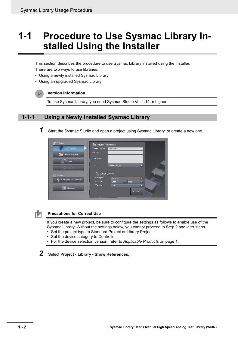
This section describes the procedure to use Sysmac Library installed using the installer.There are two ways to use libraries.• Using a newly installed Sysmac Library• Using an upgraded Sysmac Library
Version Information
To use Sysmac Library, you need Sysmac Studio Ver.1.14 or higher.
1-1-1 Using a Newly Installed Sysmac Library
1 Start the Sysmac Studio and open a project using Sysmac Library, or create a new one.
Precautions for Correct Use
If you create a new project, be sure to configure the settings as follows to enable use of theSysmac Library. Without the settings below, you cannot proceed to Step 2 and later steps.• Set the project type to Standard Project or Library Project.• Set the device category to Controller.• For the device selection version, refer to Applicable Products on page 1.
2 Select Project - Library - Show References.
1 Sysmac Library Usage Procedure
1 - 2 Sysmac Library User's Manual High Speed Analog Test Library (W607)

Device
Precautions for Correct Use
If you have multiple devices registered in the project, make sure that the currently selected de-vice is the NJ/NX-series CPU Unit or NY-series Industrial PC. If the NJ/NX-series CPU Unit orNY-series Industrial PC is not selected, the menu for browsing the library will not appear. Whenthe selected device is the NJ/NX-series CPU Unit or NY-series Industrial PC, the device icondisplayed in Multiview Explorer changes to .
3 Add Sysmac Library to the list and click OK.
Sysmac Library is read into the project.Now, when you select the Ladder Editor or ST Editor, the function blocks and functions includ-ed in the Sysmac Library appear in the Toolbox.For the procedure for adding and setting libraries in the above screen, refer to the SysmacStudio Version 1 Operation Manual (W504).
4 Insert the Sysmac Library's function blocks and functions into the circuit using one of the fol-lowing two methods.• Select the desired function block or function in the Toolbox and drag and drop it onto the
Ladder Editor.
Drug & Drop
• Right-click the Ladder Editor, select Insert Function Block in the menu, and enter the fullyqualified name (¥¥namespacename¥FBname).
1 Sysmac Library Usage Procedure
1 - 3Sysmac Library User's Manual High Speed Analog Test Library (W607)
1-1 Procedure to Use Sysm
ac Li-brary Installed U
sing the Installer
1
1-1-1 Using a N
ewly Installed Sysm
ac Library

1-1-2 Using an Upgraded Sysmac Library
1 Start Sysmac Studio and open a project in which any old-version Sysmac Library is included.
2 Select Project - Library - Show References.
Device
Precautions for Correct Use
If you have multiple devices registered in the project, make sure that the currently selected de-vice is the NJ/NX-series CPU Unit or NY-series Industrial PC. If the NJ/NX-series CPU Unit orNY-series Industrial PC is not selected, the menu for browsing the library will not appear. Whenthe selected device is the NJ/NX-series CPU Unit or NY-series Industrial PC, the device icondisplayed in Multiview Explorer changes to .
3 Select an old-version Sysmac Library and click the Delete Reference Button.
4 Add Sysmac Library to the list and click OK.
1 Sysmac Library Usage Procedure
1 - 4 Sysmac Library User's Manual High Speed Analog Test Library (W607)

Precautions for Correct Use
Upgrade the Sysmac Library version, and then execute All Program Check, and confirm thatthere are no errors in the Build Window Program Check results.From the Main Menu, select Project - All Program Check.
1 Sysmac Library Usage Procedure
1 - 5Sysmac Library User's Manual High Speed Analog Test Library (W607)
1-1 Procedure to Use Sysm
ac Li-brary Installed U
sing the Installer
1
1-1-2 Using an U
pgraded Sysmac Library

1-2 How to use Sysmac Library in theCPU Unit or Industrial PC
Even when Sysmac Library is not installed on your computer, you can use Sysmac Library by upload-ing it from the CPU Unit or Industrial PC to your computer.The procedure to use Sysmac Library in the CPU Unit or Industrial PC is as follows.
Version Information
To use Sysmac Library, you need Sysmac Studio Ver.1.14 or higher.
1 Start the Sysmac Studio and create a new project in which you want to use Sysmac Library.
2 Connect online to the CPU Unit or Industrial PC.
3 Upload the POUs in which Sysmac Library is used.Now, when you select the Ladder Editor or ST Editor, the function blocks and functions includ-ed in the Sysmac Library used in the uploaded POUs appear in the Toolbox.
4 Insert the Sysmac Library's function blocks and functions into the circuit using one of the fol-lowing two methods.• Select the desired function block or function in the Toolbox and drag and drop it onto the
Ladder Editor.
Drug & Drop
• Right-click the Ladder Editor, select Insert Function Block in the menu, and enter the fullyqualified name (¥¥namespacename¥FBname).
1 Sysmac Library Usage Procedure
1 - 6 Sysmac Library User's Manual High Speed Analog Test Library (W607)

Precautions for Correct Use
• The Sysmac Studio installs Sysmac Library library files to the specified folder on the comput-er if they are not present. However, the Sysmac Studio does not install libraries to the speci-fied folder on the computer if they are present.The specified folder here means the folder in which library files are installed by the installer.
• Note that uploading Sysmac Library from a CPU Unit or Industrial PC does not install themanual and help files for Sysmac Library, unlike installation using the installer. Please installthe manual and help files using the installer if you need them.
1 Sysmac Library Usage Procedure
1 - 7Sysmac Library User's Manual High Speed Analog Test Library (W607)
1-2 How
to use Sysmac Library
in the CPU
Unit or Industrial PC
1

1 Sysmac Library Usage Procedure
1 - 8 Sysmac Library User's Manual High Speed Analog Test Library (W607)

2High Speed Analog Test Library
This section describes the shared specifications of each FB in the High Speed AnalogTest Library.
2-1 Overview ....................................................................................................... 2 - 22-1-1 System Configuration Example .................................................................... 2 - 22-1-2 Library Configuration .................................................................................... 2 - 22-1-3 Data Flow and FB/FUN Structure ................................................................. 2 - 3
2 - 1Sysmac Library User's Manual High Speed Analog Test Library (W607)
2

2-1 OverviewThe High Speed Analog Test Library uses a time series to record the NX-series High Speed AnalogInput Unit NX-HAD£££ analog input values.Furthermore, various functions necessary for product inspections in the production process, such ascalculation of the feature amount, pass-fail judgment, etc. of the recorded data, are provided.
2-1-1 System Configuration ExampleThe figure below shows an application system configuration example for characteristic test equipmentthat uses this library.Incorporate the analog input signals of sounds, vibrations, and torque values generated during testsinto the NX-series High Speed Analog Input Unit, and use the library FB/FUN to perform workpiecepass/fail judgments.You can use the input from a photoelectric sensor, etc. as trigger input to easily obtain the analog inputdata necessary for tests.
G5-series
Servo Drive
NX-series
CPU Unit
NX102-****
EtherCAT
NX-PF0***
NX-series
Additional I/O Power Supply Unit
NX-series
High-speed Analog Input Unit
NX-HAD***
Rotational
torque
meter
Servomotor
Microphone
Vibration meter
Acceleration sensorWorkpiece
Photoelectric sensor
Analog input
Trigger input
2-1-2 Library ConfigurationThis library consists of two library files, NX_HAD and DataRecorder.These can be used either at the same time, or as separate respective units.
2 High Speed Analog Test Library
2 - 2 Sysmac Library User's Manual High Speed Analog Test Library (W607)
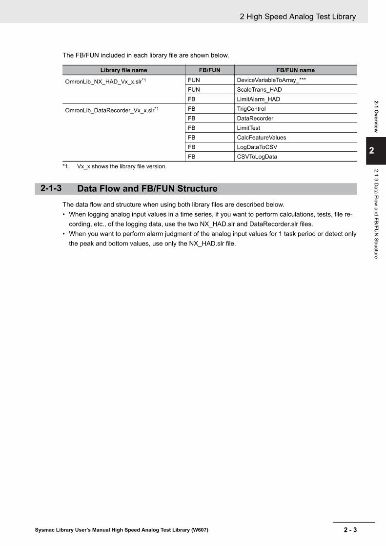
The FB/FUN included in each library file are shown below.
Library file name FB/FUN FB/FUN name
OmronLib_NX_HAD_Vx_x.slr*1 FUN DeviceVariableToArray_***FUN ScaleTrans_HADFB LimitAlarm_HAD
OmronLib_DataRecorder_Vx_x.slr*1 FB TrigControlFB DataRecorderFB LimitTestFB CalcFeatureValuesFB LogDataToCSVFB CSVToLogData
*1. Vx_x shows the library file version.
2-1-3 Data Flow and FB/FUN StructureThe data flow and structure when using both library files are described below.• When logging analog input values in a time series, if you want to perform calculations, tests, file re-
cording, etc., of the logging data, use the two NX_HAD.slr and DataRecorder.slr files.• When you want to perform alarm judgment of the analog input values for 1 task period or detect only
the peak and bottom values, use only the NX_HAD.slr file.
2 High Speed Analog Test Library
2 - 3Sysmac Library User's Manual High Speed Analog Test Library (W607)
2-1 Overview
2
2-1-3 Data Flow
and FB/FUN
Structure

Trigger ControlTrigControl
Data RecorderDataRcorder
Feature Amount Calculation
CalcFeatureValues
Log Data CSV File WriteLogDataToCSV
Log Data CSV File Read-Out
CSVToLogData
Upper and Lower Limit TestLimitTest
CSVFile
Converted Sampling Data
Recording Start Trigger
Upper Limit / Lower Limit Warning
Peak Value / Bottom Value
Log Data
Log Data Log Data(TEXT)
Average Value, Standard Deviation,Skew, Kurtosis,Maximum Value, Minimum Value
Device Output Data AssociationDeviceVariableToArray_***
Analog Input Value
Sampling Time
NX-seriesHigh Speed
Analog Input Unit
FB/FUN Included in NX_HAD_Vx_x.slr
FB Included in DataRecoder_Vx_x.slr
Sampling Data Associated with Array
NX-seriesHigh Speed Analog Input Unit Scale Conversion
NX-seriesHigh Speed Analog Input
Unit Upper and Lower Limit Warning
2 High Speed Analog Test Library
2 - 4 Sysmac Library User's Manual High Speed Analog Test Library (W607)

3Common Specifications of Func-tion Blocks
This section describes the shared specifications of each FB in the Sysmac Library.
3-1 Common Variables....................................................................................... 3 - 23-1-1 Definition of Input Variables and Output Variables........................................ 3 - 23-1-2 Execute-type Function Blocks ...................................................................... 3 - 33-1-3 Enable-type Function Blocks ........................................................................ 3 - 5
3-2 Precautions................................................................................................... 3 - 73-2-1 Nesting.......................................................................................................... 3 - 73-2-2 Instruction Options........................................................................................ 3 - 73-2-3 Re-execution of Function Blocks .................................................................. 3 - 7
3 - 1Sysmac Library User's Manual High Speed Analog Test Library (W607)
3

3-1 Common VariablesThis section describes the specifications of variables (EN, Execute, Enable, Abort, ENO, Done,CalcRslt, Enabled, Busy, CommandAborted, Error, ErrorID, and ErrorIDEx) that are used for morethan one function or function block. The specifications are described separately for functions, for exe-cute-type function blocks, and for enable-type function blocks.
3-1-1 Definition of Input Variables and Output VariablesCommon input variables and output variables used in functions and function blocks are as follows.
Variable I/O Datatype
Function/function block typeto use
Meaning DefinitionFunction blockFunc-tion
Exe-cute-type
Enable-type
EN Input BOOL OK Execute The processing is executedwhile the variable is TRUE.
Execute BOOL OK Execute The processing is executedwhen the variable changes toTRUE.
Enable BOOL OK Run The processing is executedwhile the variable is TRUE.
Abort BOOL OK Abort The processing is aborted.You can select the abortingmethod.
ENO Output BOOL OK Done The variable changes to TRUEwhen the processing ends nor-mally.It is FALSE when the process-ing ends in an error, the proc-essing is in progress, or the ex-ecution condition is not met.
Done BOOL OK Done The variable changes to TRUEwhen the processing ends nor-mally.It is FALSE when the process-ing ends in an error, the proc-essing is in progress, or the ex-ecution condition is not met.
Busy BOOL OK OK Execut-ing
The variable is TRUE when theprocessing is in progress.It is FALSE when the process-ing is not in progress.
CalcRslt LREAL OK Calcula-tion Re-sult
The calculation result is output.
3 Common Specifications of Function Blocks
3 - 2 Sysmac Library User's Manual High Speed Analog Test Library (W607)

Variable I/O Datatype
Function/function block typeto use
Meaning DefinitionFunction blockFunc-tion
Exe-cute-type
Enable-type
Enabled BOOL OK Enabled The variable is TRUE when theoutput is enabled. It is used tocalculate the control amount formotion control, temperaturecontrol, etc.
Com-mandAborted
BOOL OK Com-mandAborted
The variable changes to TRUEwhen the processing is aborted.It changes to FALSE when theprocessing is executed the nexttime again.
Error BOOL OK OK Error This variable is TRUE whilethere is an error.It is FALSE when the process-ing ends normally, the process-ing is in progress, or the execu-tion condition is not met.
ErrorID WORD OK OK ErrorCode
An error code is output.
ErrorI-DEx
DWORD OK OK Expan-sion Er-ror Code
An expansion error code is out-put.
3-1-2 Execute-type Function Blocks• Processing starts when Execute changes to TRUE.• When Execute changes to TRUE, Busy also changes to TRUE. When processing is completed nor-
mally, Busy changes to FALSE and Done changes to TRUE.• When continuously executing function blocks of the same instance, change the next Execute to
TRUE for at least one task period after Done changes to FALSE in the previous execution.• If the function block has a CommandAborted (Instruction Aborted) output variable and processing is
aborted, CommandAborted changes to TRUE and Busy changes to FALSE.• If an error occurs in the function block, Error changes to TRUE and Busy changes to FALSE.• For function blocks that output the result of calculations for motion control and temperature control,
you can use the BOOL input variable Abort to abort the FB process. When Abort changes to TRUE,CommandAborted changes to TRUE and the execution of the function block is aborted.
Abcd_instance
InOut_Val InOut_Val
DoneBusy
CommandAborted
ErrorErrorID
ErrorIDEx
Execute
Abort
Abcd
Input-Output Variables
Input Variables
Input-Output Variables
Output Variables
3 Common Specifications of Function Blocks
3 - 3Sysmac Library User's Manual High Speed Analog Test Library (W607)
3-1 Com
mon Variables
3
3-1-2 Execute-type Function Blocks
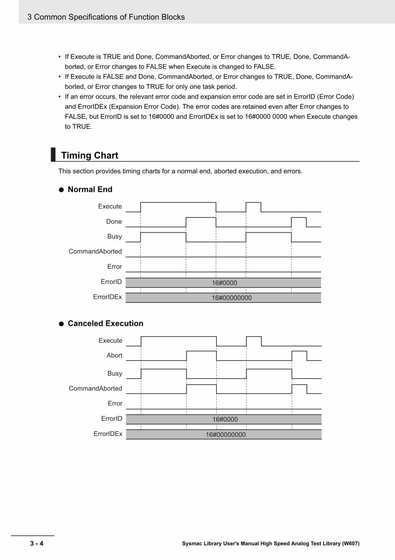
• If Execute is TRUE and Done, CommandAborted, or Error changes to TRUE, Done, CommandA-borted, or Error changes to FALSE when Execute is changed to FALSE.
• If Execute is FALSE and Done, CommandAborted, or Error changes to TRUE, Done, CommandA-borted, or Error changes to TRUE for only one task period.
• If an error occurs, the relevant error code and expansion error code are set in ErrorID (Error Code)and ErrorIDEx (Expansion Error Code). The error codes are retained even after Error changes toFALSE, but ErrorID is set to 16#0000 and ErrorIDEx is set to 16#0000 0000 when Execute changesto TRUE.
Timing ChartThis section provides timing charts for a normal end, aborted execution, and errors.
Normal End
Execute
Done
Busy
Error
ErrorID
ErrorIDEx
CommandAborted
16#0000
16#00000000
Canceled Execution
Execute
Abort
Busy
Error
ErrorID
ErrorIDEx
CommandAborted
16#0000
16#00000000
3 Common Specifications of Function Blocks
3 - 4 Sysmac Library User's Manual High Speed Analog Test Library (W607)
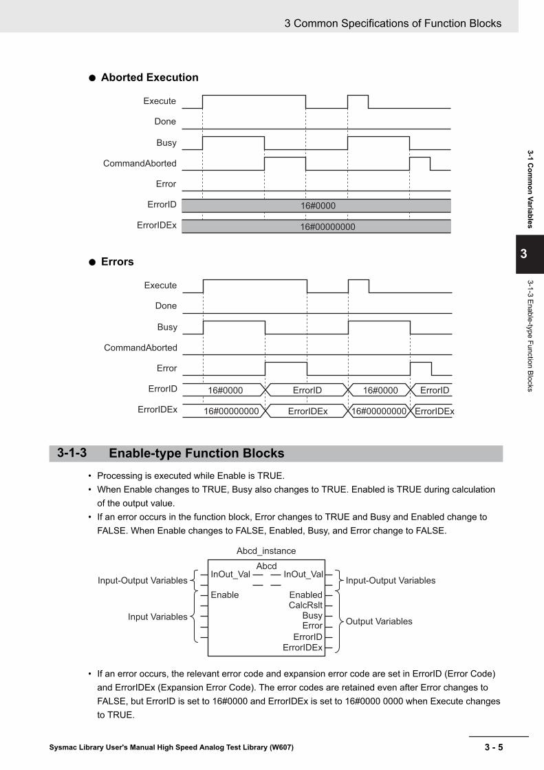
Aborted Execution
Execute
Done
Busy
Error
ErrorID
ErrorIDEx
CommandAborted
16#0000
16#00000000
Errors
Execute
Done
Busy
Error
ErrorID ErrorID
ErrorIDEx ErrorIDEx ErrorIDEx
CommandAborted
16#0000 16#0000
16#00000000 16#00000000
ErrorID
3-1-3 Enable-type Function Blocks• Processing is executed while Enable is TRUE.• When Enable changes to TRUE, Busy also changes to TRUE. Enabled is TRUE during calculation
of the output value.• If an error occurs in the function block, Error changes to TRUE and Busy and Enabled change to
FALSE. When Enable changes to FALSE, Enabled, Busy, and Error change to FALSE.
Abcd_instance
InOut_Val
Enable EnabledCalcRslt
BusyError
ErrorIDErrorIDEx
InOut_ValAbcd
Input-Output Variables
Input Variables
Input-Output Variables
Output Variables
• If an error occurs, the relevant error code and expansion error code are set in ErrorID (Error Code)and ErrorIDEx (Expansion Error Code). The error codes are retained even after Error changes toFALSE, but ErrorID is set to 16#0000 and ErrorIDEx is set to 16#0000 0000 when Execute changesto TRUE.
3 Common Specifications of Function Blocks
3 - 5Sysmac Library User's Manual High Speed Analog Test Library (W607)
3-1 Com
mon Variables
3
3-1-3 Enable-type Function Blocks

• For function blocks that calculate the control amount for motion control, temperature control, etc.,Enabled is FALSE when the value of CalcRslt (Calculation Result) is incorrect. In such a case, donot use CalcRslt. In addition, after the function block ends normally or after an error occurs, the val-ue of CalcRslt is retained until Enable changes to TRUE. The control amount will be calculatedbased on the retained CalcRslt value, if it is the same instance of the function block that changedEnable to TRUE. If it is a different instance of the function block, the control amount will be calculat-ed based on the initial value.
Timing ChartsThis section provides timing charts for a normal end, aborted execution, and errors.
Normal End
Enable
Enabled
CalcRslt
Busy
Error
ErrorID
ErrorIDEx
16#0000
16#00000000
RetentionRetention
Errors
16#0000
ErrorID
Enable
Enabled
CalcRslt
Busy
Error
ErrorID ErrorID
ErrorIDEx
16#0000 16#0000
16#00000000
16#00000000
ErrorID
ErrorID ErrorID
ErrorID
RetentionRetention
3 Common Specifications of Function Blocks
3 - 6 Sysmac Library User's Manual High Speed Analog Test Library (W607)

3-2 PrecautionsThis section provides precautions for the use of this function block.
3-2-1 NestingYou can nest calls to this function block for up to four levels.Refer to NJ/NX-series CPU Unit Software User's Manual (W501) or NY-series IPC Machine ControllerIndustrial Panel PC / Industrial Box PC Software User's Manual (W558) for details on the nesting func-tion block.
3-2-2 Instruction OptionsYou cannot use the upward differentiation option for this function block.
3-2-3 Re-execution of Function BlocksExecute-type function blocks cannot be re-executed by the same instance.If you do so, the output value will be the initial value.Refer to NJ/NX-series CPU Unit Motion Control User's Manual (W507) or NY-series IPC MachineController Industrial Panel PC / Industrial Box PC Motion Control User's Manual (W559) for details onre-execution.
3 Common Specifications of Function Blocks
3 - 7Sysmac Library User's Manual High Speed Analog Test Library (W607)
3-2 Precautions
3
3-2-1 Nesting

3 Common Specifications of Function Blocks
3 - 8 Sysmac Library User's Manual High Speed Analog Test Library (W607)

4FB/FUN Individual Specifications(NX_HAD)
This section describes the FB/FUN individual specifications included in NX_HAD.slr.
DeviceVariableToArray_*** .................................................................................... 4 - 2ScaleTrans_HAD................................................................................................... 4 - 11LimitAlarm_HAD................................................................................................... 4 - 14
4 - 1Sysmac Library User's Manual High Speed Analog Test Library (W607)
4

DeviceVariableToArray_***Bind the analog input values for 1 task period imported from the NX-series High Speed Analog InputUnit to a single array variable.The FB/FUN end _*** shows the maximum value of the FUN input sampling number with either 020 or100. Select the FUN most suitable for the required sampling number.
FB/FUNname Name FB/
FUN Graphic expression ST expression
Device-Variable-ToAr-ray_100
DeviceOutputDataBinding
FUN \\OmronLib\NX_HAD\DeviceVariableToArray_100
EN
Input01
Input02
ENO
NextPos
Input03
Input04
Input06
Input05
Input07
Input08
Input09
Input10
InputSize
DataArray DataArray
StartPos
DeviceVariableToAr-ray_100(Input01,Input02,Input03,Input04,Input05,Input06,Input07,Input08,Input09,Input10,StartPos,InputSize,NextPos,DataArray);
Device-Variable-ToAr-ray_020
\\OmronLib\NX_HAD\DeviceVariableToArray_020
EN
Input01
Input02
ENO
NextPos
StartPos
InputSize
DataArray DataArray
DeviceVariableToAr-ray_020(Input01,Input02,StartPos,InputSize,NextPos,DataArray);
Library InformationItem Description
Library file name OmronLib_NX_HAD_Vx_x.slr (x shows the version)Namespace OmronLib\NX_HADFunction block and func-tion number
DeviceVariableToArray_100: 00192DeviceVariableToArray_020: 00191
Source code Not Published
Input VariablesMeaning Data type Description Valid range Unit Default
EN Execute BOOL TRUE: ExecuteFALSE: Do not execute
TRUE,FALSE
― FALSE
4 FB/FUN Individual Specifications (NX_HAD)
4 - 2 Sysmac Library User's Manual High Speed Analog Test Library (W607)

Meaning Data type Description Valid range Unit DefaultInput01[] -Input10[]
Device Out-putData 01 to10
AR-RAY[0..9]OF INT
Inputs the Analog InputValue acquired from theI/O data
― ― ―
StartPos Start posi-tion
UINT Specifies whichDataArray[] element No.the device output data isbound from.Refer to Function on page4 - 3 for details.
Dependson datatype.
― 0
InputSize Number ofdata
UINT Inputs the Samplingnumber acquired from theI/O data
Dependson datatype.
― 1
Output VariablesMeaning Data type Description Valid range Unit Default
ENO Binding Re-sults
BOOL TRUE: Normal endFALSE: Error end, or exe-cution condition not met.
TRUE,FALSE
― ―
NextPos Next Posi-tion
UINT Output the next boundstart element No.Refer to Function on page4 - 3 for details.
Dependson datatype.
― ―
Input-Output VariablesMeaning Data type Description Valid range Unit Default
DataAr-ray[]*1
Bound Data ARRAY[*]OF REAL
Stores the bound inputdata
Dependson datatype.
― ―
*1. The number of array elements is arbitrary. However, the number of array elements must be equal to theInputSize or more. In addition, the array element start number can be either 0 or a number other than 0.
FunctionSince the analog values obtained from the NX-series High Speed Analog Input Unit are single or multi-ple ARRAY[0..9] OF INT type arrays, bind these to a single REAL type array.Bind the data specified in InputSize in order from Input01[0].When the data has been successfully bound, output TRUE to ENO.In the cases below, output FALSE to ENO without binding to an array.• When InputSize is 0• When the number of DataArray[] array elements is less than the InputSize• When StartPos is outside the DataArray[] range
Example: When the number of DataArray[] array elements is 100 and InputSize is 95, bind untilInput10[4].
4 FB/FUN Individual Specifications (NX_HAD)
4 - 3Sysmac Library User's Manual High Speed Analog Test Library (W607)
DeviceVariableToA
rray_***
4
Output Variables

Input01[] Ch Analog Input Value 1-10
Input02[] Analog Input Value 11-20Ch
Input10[] Analog Input Value 91-100Ch
[0] [1] [2] [3] [4] [5] [6] [7] [8] [9]
[1] [2] [3] [4] [5] [6] [7] [8] [9][0]
[1] [2] [3] [4] [5] [6] [7] [8] [9][0]
Input01 Input02 Input10
[0] [1] [2] [3] [4] [5] [6] [7] [8] [9] [10][11][12][13][14][15][16][17][18][19] [90][91][92][93][94][95][96][97][98][99]
DataArray[]
£←
£←
£←
• Series ConnectionIf the series connection for this FUN is performed as shown below, you can bind data in excess of themaximum value of a single FUN input sampling number.In addition, you can also perform connections mixing the DeviceVariableToArray_020 and DeviceVar-iableToArray_100.
Example: When the sampling number is 40 items.
\\OmronLib\NX_HAD\DeviceVariableToArray_020IO_Data_Is_Valid
Input01
Input02
StartPosUINT#0
InputSize
DataArray DataArray Ch1_PeriodicData
Ch1_PeriodicData
Ch1_PeriodicData
EN ENO
NextPos
\\OmronLib\NX_HAD\DeviceVariableToArray_020
Input01
Input02
StartPos
InputSize
DataArray DataArray
EN ENO
NextPos
Success_Concatenate
NextPos NextPos
N1_Ch1_Analog_Input_Value_1_10
N1_Ch1_Analog_Input_Value_11_20
N1_Ch1_Number_of_Samplings
Ch1_PeriodicData
N1_Ch1_Analog_Input_Value_21_30
N1_Ch1_Analog_Input_Value_31_40
N1_Ch1_Number_of_Samplings
Precautions for Correct UseWhen using a series connection, perform it in the following way.• In all InputSize, input the input Ch sampling number bound from the I/O data. In the example,
N1_Ch1_Number_of_Sampling is input.• Specify the same variable in DataArray[] for each FUN in the series connection.• For the number of DataArray[] array elements, specify a value equal to the InputSize or more.• For the StartPos of the 1st FUN, input 0.• For the StartPos of the 2nd and later FUN , input the NextPos value for the FUN that was immedi-
ately previous.
4 FB/FUN Individual Specifications (NX_HAD)
4 - 4 Sysmac Library User's Manual High Speed Analog Test Library (W607)

Sample Programming 1The NX-series High Speed Analog Input Unit binds the analog input values sampled 100 times per 1task period to a single array variable. Furthermore, this program performs a scale conversion of thebound data, and monitors the upper and lower limits of the data.This is an example of the connection of the NX-series High Speed Analog Input Unit to an NX-seriesCPU Unit.
System ConfigurationThe system configuration is as shown below.
(a) (b) (c)
Output Equipment
Let-ter Description Model Description
(a) NX-series CPU Units NX102-££££ —(b) I/O Power Additional Supply Unit NX-PF0730 • NX Unit No.: 1(c) NX-series High Speed Analog Unit NX-HAD401 • NX Unit No.: 2
• Channel Used: Ch1
Unit Operation SettingsSet the NX-series High Speed Analog Input Unit as shown in the table below. Refer to NX-seriesAnalog I/O Unit High Speed Analog Input Unit User's Manual (SBCA-461) for the setting method.
Setting Item Setting Value Setting MeaningCh1 Valid / Invalid TRUE Ch1 ValidCh1 Range Setting 0 -10 to +10 VCh1 Sampling Setting 100 100 times
Program• External Variables
Name Data typeConstant
Comment
NXBus_N2_NX_Unit_I_O_Data_Active_Status BOOL
4 FB/FUN Individual Specifications (NX_HAD)
4 - 5Sysmac Library User's Manual High Speed Analog Test Library (W607)
DeviceVariableToA
rray_***
4
Sample Program
ming 1

Name Data typeConstant
Comment
NXBus_N2_NX_Unit_Error_Status BOOLN2_Ch1_Number_of_Samplings UINTN2_Ch1_Analog_Input_Value_1_10 ARRAY[0..9] OF INTN2_Ch1_Analog_Input_Value_11_20 ARRAY[0..9] OF INTN2_Ch1_Analog_Input_Value_21_30 ARRAY[0..9] OF INTN2_Ch1_Analog_Input_Value_31_40 ARRAY[0..9] OF INTN2_Ch1_Analog_Input_Value_41_50 ARRAY[0..9] OF INTN2_Ch1_Analog_Input_Value_51_60 ARRAY[0..9] OF INTN2_Ch1_Analog_Input_Value_61_70 ARRAY[0..9] OF INTN2_Ch1_Analog_Input_Value_71_80 ARRAY[0..9] OF INTN2_Ch1_Analog_Input_Value_81_90 ARRAY[0..9] OF INTN2_Ch1_Analog_Input_Value_91_100 ARRAY[0..9] OF INTCh1_Input_Array100 ARRAY[0..99] OF REAL Analog Input Value for
1 Task Period
• Internal Variables
Name Data type Default AT
Retention
Constant
Comment
LimitAlarm_instance OmronLib\NX_HAD\Limi-tAlarm_HAD
IO_Data_Is_Valid BOOL Set to TRUE whenthe input value fromthe NX-series HighSpeed Analog Unitis normal
Success_Concatenate BOOLAlarm BOOL Set to TRUE when
any of QHH, QH,QL, or QLL isTRUE
QHH BOOLQH BOOLQL BOOLQLL BOOLPeakVal REALBottomBal REALClear_PkBtm BOOL FALSEEN_P1 BOOL FALSE While this variable's
value is TRUE,scale conversionand alarm judgmentare executed
• Task SettingDeploy in the primary periodic task.
4 FB/FUN Individual Specifications (NX_HAD)
4 - 6 Sysmac Library User's Manual High Speed Analog Test Library (W607)

• LD Program
(1) Check that normal data is being received from the NX-series High Speed Analog Input Unit.
(2) Bind the analog input values for 1 task period to the single variable Ch1_Input_Array100[].
(3) After scale conversion of the analog input values for 1 task period, and when the input valuesare outside the range set in HH, H, L, and LL, set Alarm to TRUE.
Scale Conversion Setting -32,000 to +32,000 → 0 to 10,000Alarm Settings Top Upper Limit HH Alarm When 9,000 is exceeded
Upper Limit H Alarm When 7,000 is exceededLower Limit L Alarm When less than 3,000Bottom Lower Limit LL Alarm When less than 1,000
Sample Programming 2The NX-series High Speed Analog Input Unit binds the analog input values sampled 100 times per 1task period to a single array variable. Furthermore, this program performs a scale conversion of thebound data, and monitors the upper and lower limits of the data.This is an example of the connection of the NX-series High Speed Analog Input Unit to an EtherCatslave terminal.
System ConfigurationThe system configuration is as shown below.
4 FB/FUN Individual Specifications (NX_HAD)
4 - 7Sysmac Library User's Manual High Speed Analog Test Library (W607)
DeviceVariableToA
rray_***
4
Sample Program
ming 2
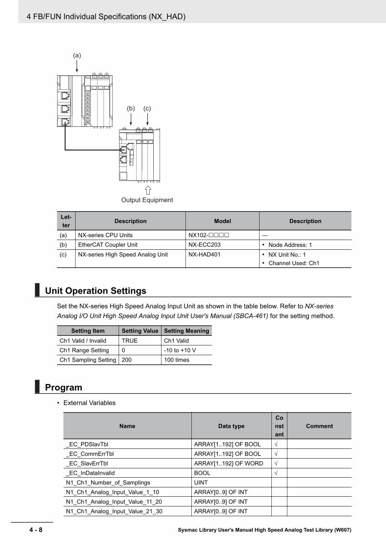
(a)
(b) (c)
Output Equipment
Let-ter Description Model Description
(a) NX-series CPU Units NX102-££££ —(b) EtherCAT Coupler Unit NX-ECC203 • Node Address: 1(c) NX-series High Speed Analog Unit NX-HAD401 • NX Unit No.: 1
• Channel Used: Ch1
Unit Operation SettingsSet the NX-series High Speed Analog Input Unit as shown in the table below. Refer to NX-seriesAnalog I/O Unit High Speed Analog Input Unit User's Manual (SBCA-461) for the setting method.
Setting Item Setting Value Setting MeaningCh1 Valid / Invalid TRUE Ch1 ValidCh1 Range Setting 0 -10 to +10 VCh1 Sampling Setting 200 100 times
Program• External Variables
Name Data typeConstant
Comment
_EC_PDSlavTbl ARRAY[1..192] OF BOOL √_EC_CommErrTbl ARRAY[1..192] OF BOOL √_EC_SlavErrTbl ARRAY[1..192] OF WORD √_EC_InDataInvalid BOOL √N1_Ch1_Number_of_Samplings UINTN1_Ch1_Analog_Input_Value_1_10 ARRAY[0..9] OF INTN1_Ch1_Analog_Input_Value_11_20 ARRAY[0..9] OF INTN1_Ch1_Analog_Input_Value_21_30 ARRAY[0..9] OF INT
4 FB/FUN Individual Specifications (NX_HAD)
4 - 8 Sysmac Library User's Manual High Speed Analog Test Library (W607)

Name Data typeConstant
Comment
N1_Ch1_Analog_Input_Value_31_40 ARRAY[0..9] OF INTN1_Ch1_Analog_Input_Value_41_50 ARRAY[0..9] OF INTN1_Ch1_Analog_Input_Value_51_60 ARRAY[0..9] OF INTN1_Ch1_Analog_Input_Value_61_70 ARRAY[0..9] OF INTN1_Ch1_Analog_Input_Value_71_80 ARRAY[0..9] OF INTN1_Ch1_Analog_Input_Value_81_90 ARRAY[0..9] OF INTN1_Ch1_Analog_Input_Value_91_100 ARRAY[0..9] OF INTCh1_Input_Array100 ARRAY[0..99] OF REAL Analog Input Value for
1 Task Period• Internal Variables
Name Data type Default AT
Retention
Constant
Comment
LimitAlarm_instance OmronLib\NX_HAD\Limi-tAlarm_HAD
IO_Data_Is_Valid BOOL Set to TRUE whenthe input value fromthe NX-series HighSpeed Analog Unitis normal
Success_Concatenate BOOLAlarm BOOL Set to TRUE when
any of QHH, QH,QL, or QLL isTRUE
QHH BOOLQH BOOLQL BOOLQLL BOOLPeakVal REALBottomBal REALClear_PkBtm BOOL FALSEEN_P1 BOOL FALSE While this variable's
value is TRUE,scale conversionand alarm judgmentare executed
• Task SettingDeploy in the primary periodic task.
• LD Program
(1) Check that normal data is being received from the NX-series High Speed Analog Input Unit.
4 FB/FUN Individual Specifications (NX_HAD)
4 - 9Sysmac Library User's Manual High Speed Analog Test Library (W607)
DeviceVariableToA
rray_***
4
Sample Program
ming 2

(2) Bind the analog input values for 1 task period to the single variable Ch1_Input_Array100[].
(3) After scale conversion of the analog input values for 1 task period, and when the input valuesare outside the range set in HH, H, L, and LL, set Alarm to TRUE.
Scale Conversion Setting -32,000 to +32,000 → 0 to 10,000Alarm Settings Top Upper Limit HH Alarm When 9,000 is exceeded
Upper Limit H Alarm When 7,000 is exceededLower Limit L Alarm When less than 3,000Bottom Lower Limit LL Alarm When less than 1,000
Precautions for Correct Use
• The sample programming shows only the portion of a program that uses the function or func-tion block from the library. When programming actual applications, also program safety cir-cuits, device interlocks, I/O with other devices, and other control procedures.
• Create a user program that will produce the intended device operation.• Check the user program for proper execution before you use it for actual operation.
4 FB/FUN Individual Specifications (NX_HAD)
4 - 10 Sysmac Library User's Manual High Speed Analog Test Library (W607)

ScaleTrans_HADPerform scale conversion of data imported from the NX-series High Speed Analog Input Unit.
FB/FUNname Name FB/
FUN Graphic expression ST expression
Scale-Trans_HAD
For NX-seriesHighSpeedAnalogInputUnitScaleConver-sion
FUN \\OmronLib\NX_HAD\ScaleTrans_HADEN
SclIn
SclOut
SclIn
ENO
SclOut
SclOfs
InputSize
X0
Y0
Y1
X1
ScaleTrans_HAD(SclIn,SclOut,X0,Y0,X1,Y1,ScaleOfs,InputSize);
Library InformationItem Description
Library file name OmronLib_NX_HAD_Vx_x.slr (x shows the version)Namespace OmronLib\NX_HADFunction block and func-tion number
00193
Source code Not Published
Input VariablesMeaning Data type Description Valid range Unit Default
EN Execute BOOL TRUE: ExecuteFALSE: Do not execute
TRUE,FALSE
— FALSE
X0 InputRangeLower LimitValue
REAL Lower limit value of inputrange
Dependson datatype.
— -32000
Y0 OutputRangeLower LimitValue
REAL Lower limit value of outputrange
Dependson datatype.
— -32000
X1 InputRange Up-per LimitValue
REAL Upper limit value of inputrange
Dependson datatype.
— 32000
Y1 OutputRange Up-per LimitValue
REAL Upper limit value of outputrange
Dependson datatype.
— 32000
4 FB/FUN Individual Specifications (NX_HAD)
4 - 11Sysmac Library User's Manual High Speed Analog Test Library (W607)
ScaleTrans_HA
D
4
Library Information

Meaning Data type Description Valid range Unit DefaultSclOfs Offset Val-
ueREAL Offset value exceeding
the output valueDependson datatype.
— 0.0
InputSize Number ofdata
UINT Inputs the Samplingnumber acquired from theI/O data
1 to 1000 — 1
Output VariablesMeaning Data type Description Valid range Unit Default
ENO ConversionResults
BOOL TRUE: Normal endFALSE: Error end, or exe-cution condition not met.
TRUE,FALSE
— —
Input-Output VariablesMeaning Data type Description Valid range Unit Default
SclIn[]*1 Input Value ARRAY[*]OF REAL
Data array targeted forconversion
Dependson datatype.
— —
SclOut[]*2 Output Val-ue
ARRAY[*]OF REAL
Data array after scaleconversion
Dependson datatype.
— —
*1. The number of array elements is arbitrary. However, the number of array elements must be equal to theInputSize or more. In addition, the array element start number can be either 0 or a number other than 0.
*2. The number of array elements is arbitrary. However, the number of array elements must be the same asSclIn[]. In addition, the array element start number can be either 0 or a number other than 0. Even if the startnumber for the array elements differs from SclIn[], it can still be executed.
FunctionConvert each of the SclIn[] elements from the input range specified in X0 and X1 to the output rangespecified from Y0 to Y1.Store the sum of the value converted to the output range and SclOfs in SclOut[].You can perform execution even if the input value is outside the input range.When conversion is successful, output TRUE to ENO.In the cases below, output FALSE to ENO without performing scale conversion.• When the number of SclIn[] and SclOut[] array elements is less than the InputSize• When SclIn[] and SclOut[] array element numbers do not match
However, differences in the Start No. are possible• When X0 and X1 are equal, or when Y0 and Y1 are equal• When InputSize is 0 or at 1001 or more
4 FB/FUN Individual Specifications (NX_HAD)
4 - 12 Sysmac Library User's Manual High Speed Analog Test Library (W607)
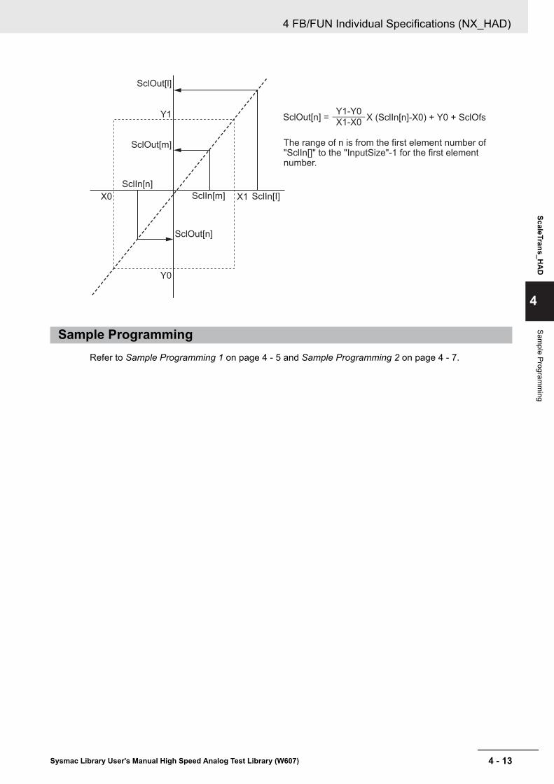
SclOut[l]
SclOut[m]
SclIn[n]
SclIn[m] SclIn[I]
SclOut[n]
Y1
X0
Y0
X1
The range of n is from the first element number of "SclIn[]" to the "InputSize"-1 for the first element number.
SclOut[n] =Y1-Y0
X1-X0X (SclIn[n]-X0) + Y0 + SclOfs
Sample ProgrammingRefer to Sample Programming 1 on page 4 - 5 and Sample Programming 2 on page 4 - 7.
4 FB/FUN Individual Specifications (NX_HAD)
4 - 13Sysmac Library User's Manual High Speed Analog Test Library (W607)
ScaleTrans_HA
D
4
Sample Program
ming

LimitAlarm_HADPerform the top upper limit, upper limit, lower limit, and bottom lower limit alarms for the data importedfrom the NX-series High Speed Analog Input Unit.
FB/FUNname Name FB/
FUN Graphic expression ST expression
LimitA-larm_HAD
For NX-seriesHighSpeedAnalogInputUnitUpperandLowerLimitAlarm
FB
\\OmronLib\NX_HAD\LimitAlarm_HAD
LimitAlarm_HAD_instance
Enable
HH
H
Input
L
LL
EPS
AlarmSelect
LatchSelect
InputSize
Clear_PeakBottomVal
Q
QHH
QH
Input
QL
QLL
PeakVal
BottomVal
Error
ErrorIDEx
ErrorID
LimitAlarm_HAD_in-stance(Enable,HH,H,Input,L,LL,EPS,AlarmSelect,LatchSelect,Clear_PeakBot-tomVal,InputSize,Q,QHH,QH,QL,QLL,PeakVal,BottomVal,Error,ErrorID,ErrorIDEx);
Library InformationItem Description
Library file name OmronLib_NX_HAD_Vx_x.slr (x shows the version)Namespace OmronLib\NX_HADFunction block and func-tion number
00194
Source code Not Published
Input VariablesMeaning Data type Description Valid range Unit Default
Enable Execute BOOL TRUE: ExecuteFALSE: Do not execute
TRUE,FALSE
— FALSE
HH Top UpperLimit Set-ting Value
REAL Top Upper Limit SettingValue of Input Value
Dependson datatype.
— 0.0
4 FB/FUN Individual Specifications (NX_HAD)
4 - 14 Sysmac Library User's Manual High Speed Analog Test Library (W607)
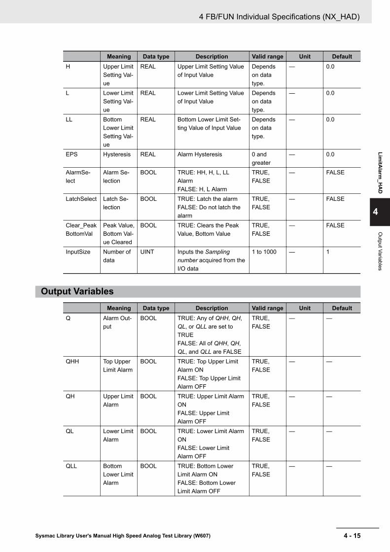
Meaning Data type Description Valid range Unit DefaultH Upper Limit
Setting Val-ue
REAL Upper Limit Setting Valueof Input Value
Dependson datatype.
— 0.0
L Lower LimitSetting Val-ue
REAL Lower Limit Setting Valueof Input Value
Dependson datatype.
— 0.0
LL BottomLower LimitSetting Val-ue
REAL Bottom Lower Limit Set-ting Value of Input Value
Dependson datatype.
— 0.0
EPS Hysteresis REAL Alarm Hysteresis 0 andgreater
— 0.0
AlarmSe-lect
Alarm Se-lection
BOOL TRUE: HH, H, L, LLAlarmFALSE: H, L Alarm
TRUE,FALSE
— FALSE
LatchSelect Latch Se-lection
BOOL TRUE: Latch the alarmFALSE: Do not latch thealarm
TRUE,FALSE
— FALSE
Clear_PeakBottomVal
Peak Value,Bottom Val-ue Cleared
BOOL TRUE: Clears the PeakValue, Bottom Value
TRUE,FALSE
— FALSE
InputSize Number ofdata
UINT Inputs the Samplingnumber acquired from theI/O data
1 to 1000 — 1
Output VariablesMeaning Data type Description Valid range Unit Default
Q Alarm Out-put
BOOL TRUE: Any of QHH, QH,QL, or QLL are set toTRUEFALSE: All of QHH, QH,QL, and QLL are FALSE
TRUE,FALSE
— —
QHH Top UpperLimit Alarm
BOOL TRUE: Top Upper LimitAlarm ONFALSE: Top Upper LimitAlarm OFF
TRUE,FALSE
— —
QH Upper LimitAlarm
BOOL TRUE: Upper Limit AlarmONFALSE: Upper LimitAlarm OFF
TRUE,FALSE
— —
QL Lower LimitAlarm
BOOL TRUE: Lower Limit AlarmONFALSE: Lower LimitAlarm OFF
TRUE,FALSE
— —
QLL BottomLower LimitAlarm
BOOL TRUE: Bottom LowerLimit Alarm ONFALSE: Bottom LowerLimit Alarm OFF
TRUE,FALSE
— —
4 FB/FUN Individual Specifications (NX_HAD)
4 - 15Sysmac Library User's Manual High Speed Analog Test Library (W607)
LimitA
larm_H
AD
4
Output Variables

Meaning Data type Description Valid range Unit DefaultPeakVal Peak Value REAL Maximum Input Value Depends
on datatype.
— —
BottomVal Bottom Val-ue
REAL Minimum Input Value Dependson datatype.
— —
Error Error BOOL TRUE: Error endFALSE: Normal end, exe-cution in progress, or exe-cution condition not met.
TRUE,FALSE
— —
ErrorID Error Code WORD This is the error ID for anerror end.The value is 16#0 for anormal end.
*1 — —
ErrorIDEx ExpansionError Code
DWORD This is the error ID for anExpansion Unit HardwareError.The value is 16#0 for anormal end.
*1 — —
*1. Refer to Troubleshooting on page 4 - 19 for details.
Input-Output VariablesMeaning Data type Description Valid range Unit Default
Input[]*1 Input Value ARRAY[*]OF REAL
Data array targeted formonitoring
Dependson datatype.
— —
*1. The number of array elements is arbitrary. However, the number of array elements must be equal to theInputSize or more. In addition, the array element start number can be either 0 or a number other than 0.
FunctionWhile Enable is TRUE, when each element value in Input[] exceeds the HH or H setting value, orwhen they fall short of the L or LL setting value, output an alarm.The relationship of the input and each setting value to the alarm output is shown below.• When Input[] is larger than HH, set QHH to TRUE.
When QHH is TRUE, and the input value becomes smaller than HH-EPS, set QHH to FALSE.• When Input[] is larger than H, set QH to TRUE.
When QH is TRUE, and the input value becomes smaller than H-EPS, set QH to FALSE.• When Input[] is smaller than L, set QL to TRUE.
When QL is TRUE, and the input value becomes larger than L+EPS, set QL to FALSE.• When Input[] is smaller than LL, set QLL to TRUE.
When QLL is TRUE, and the input value becomes larger than LL+EPS, set QLL to FALSE.• When any of QHH, QH, QL, or QLL is TRUE, set Q to TRUE.
If AlarmSelect is TRUE, set the four HH, H, L, and LL to alarm judgment.
If AlarmSelect is FALSE, set the two H and L to alarm judgment. In this case, QHH and QLL are al-ways FALSE.
4 FB/FUN Individual Specifications (NX_HAD)
4 - 16 Sysmac Library User's Manual High Speed Analog Test Library (W607)
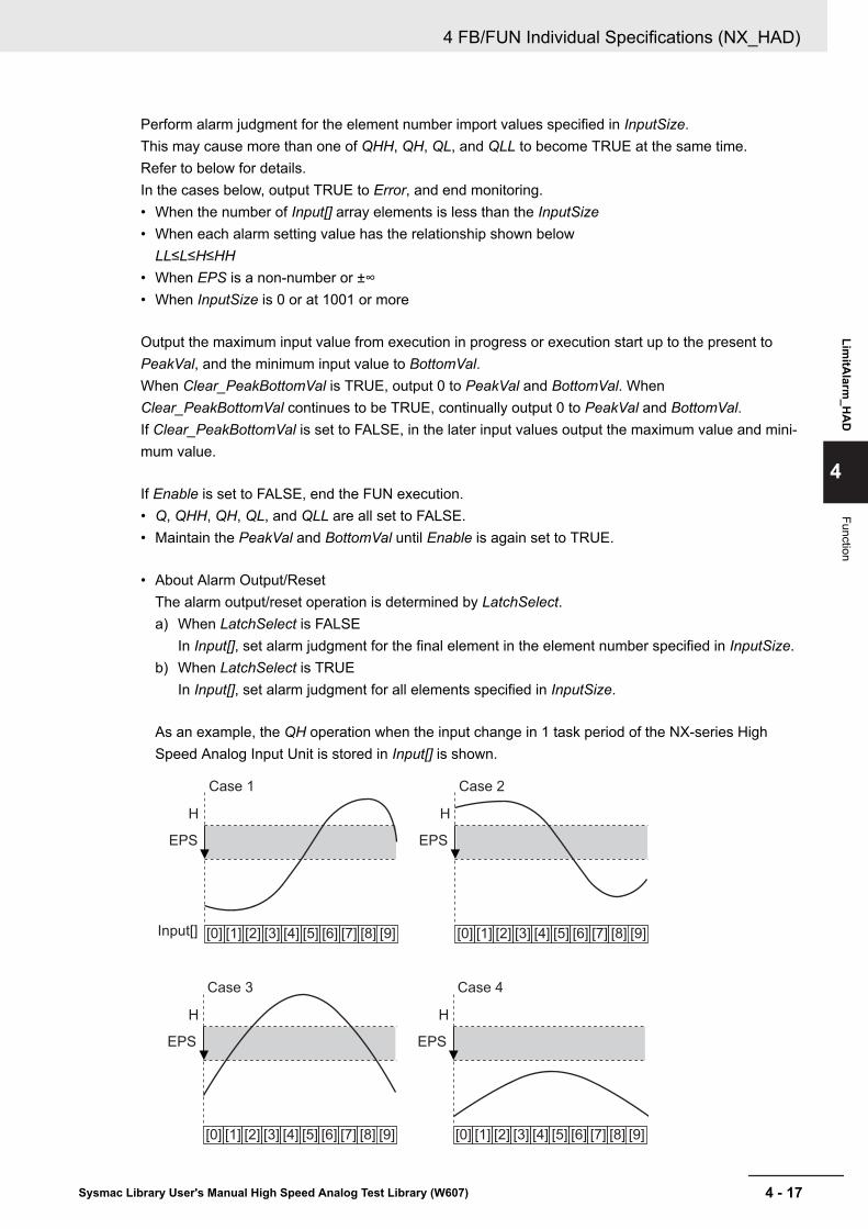
Perform alarm judgment for the element number import values specified in InputSize.This may cause more than one of QHH, QH, QL, and QLL to become TRUE at the same time.Refer to below for details.In the cases below, output TRUE to Error, and end monitoring.• When the number of Input[] array elements is less than the InputSize• When each alarm setting value has the relationship shown below
LL≤L≤H≤HH• When EPS is a non-number or ±∞• When InputSize is 0 or at 1001 or more
Output the maximum input value from execution in progress or execution start up to the present toPeakVal, and the minimum input value to BottomVal.When Clear_PeakBottomVal is TRUE, output 0 to PeakVal and BottomVal. WhenClear_PeakBottomVal continues to be TRUE, continually output 0 to PeakVal and BottomVal.If Clear_PeakBottomVal is set to FALSE, in the later input values output the maximum value and mini-mum value.
If Enable is set to FALSE, end the FUN execution.• Q, QHH, QH, QL, and QLL are all set to FALSE.• Maintain the PeakVal and BottomVal until Enable is again set to TRUE.
• About Alarm Output/ResetThe alarm output/reset operation is determined by LatchSelect.a) When LatchSelect is FALSE
In Input[], set alarm judgment for the final element in the element number specified in InputSize.b) When LatchSelect is TRUE
In Input[], set alarm judgment for all elements specified in InputSize.
As an example, the QH operation when the input change in 1 task period of the NX-series HighSpeed Analog Input Unit is stored in Input[] is shown.
Case 1
H
EPS
Case 2
H
EPS
Case 3
H
EPS
Case 4
H
EPS
Input[] [0] [1] [2] [3] [4] [5] [6] [7] [8] [9] [0] [1] [2] [3] [4] [5] [6] [7] [8] [9]
[0] [1] [2] [3] [4] [5] [6] [7] [8] [9] [0] [1] [2] [3] [4] [5] [6] [7] [8] [9]
4 FB/FUN Individual Specifications (NX_HAD)
4 - 17Sysmac Library User's Manual High Speed Analog Test Library (W607)
LimitA
larm_H
AD
4
Function

LatchSelectQH
Case 1 Case 2 Case 3 Case 4FALSE TRUE FALSE FALSE FALSETRUE TRUE TRUE TRUE FALSE
• Setting changes during executionConstantly reflect HH, H, L, LL, and EPS while execution is in progress.Even if changed during execution, AlarmSelect and LatchSelect will not be reflected.If changed during execution, set the alarm output to FALSE, and perform alarm judgment at the set-ting value after the change.
Timing ChartThe timing charts are shown below.• If Enable is set to TRUE, start the alarm monitoring.
Output the maximum input value from execution start up to the present to PeakVal, and the mini-mum input value to BottomVal.
• If Enable is set to FALSE, end the alarm monitoring.• While Clear_PeakBottomVal is TRUE, output 0 to PeakVal and BottomVal.• If an error occurs, set Error to TRUE. At the same time, output ErrorID and ErrorIDEx.• When an error occurs, retain Error while Enable is TRUE.
After Enable is set to FALSE, retain ErrorID and ErrorIDEx until Enable is again set to TRUE.
• Timing Chart for Normal End
Enable
Q
QHH
QH
QL
QLL
PeakVal 0 Maximum Input Value
Minimum Input Value
Maximum Input Value
Minimum Input Value0
0
0
0
0BootomVal
Error
ErrorID
ErrorIDEx
Clear_PeakBottomVal
• Timing Chart for Error End
4 FB/FUN Individual Specifications (NX_HAD)
4 - 18 Sysmac Library User's Manual High Speed Analog Test Library (W607)
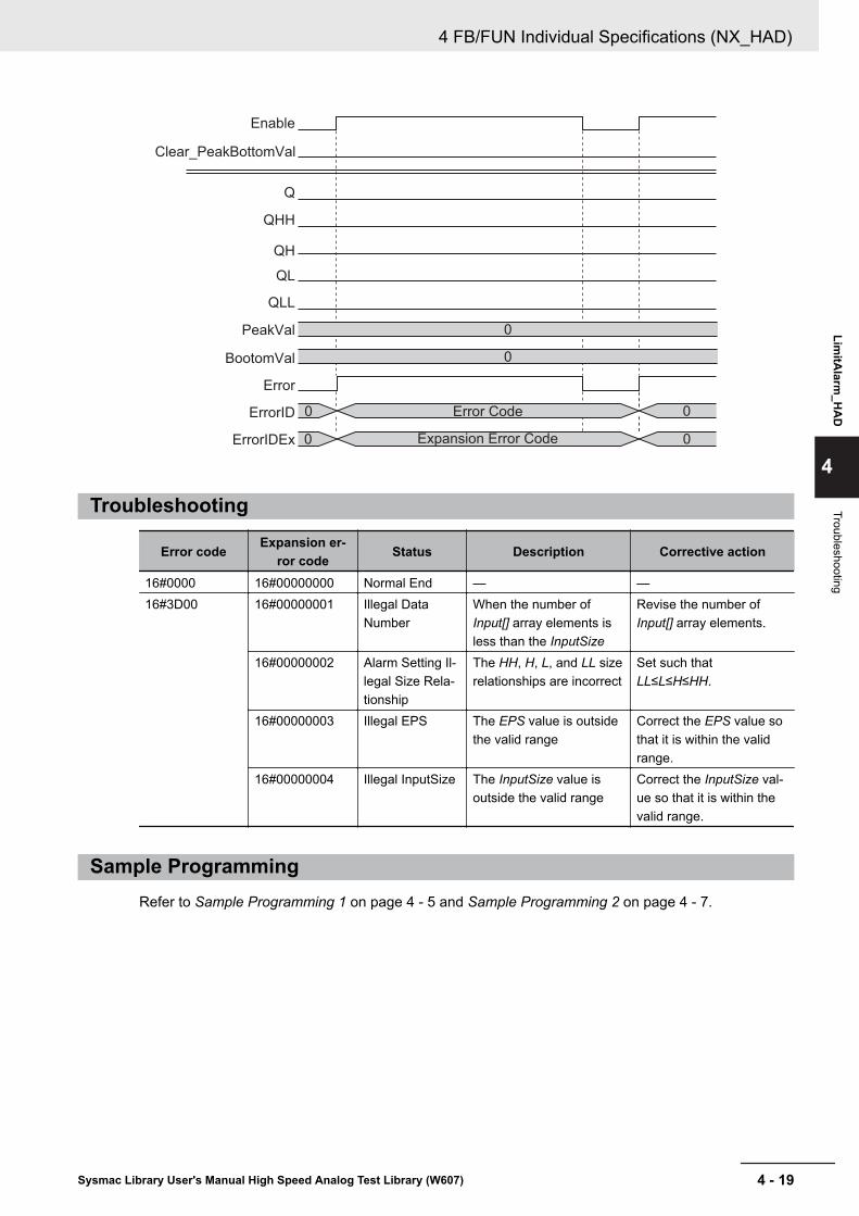
Enable
Q
QHH
QH
QL
QLL
PeakVal 0
Error Code
Expansion Error Code
0
0
0
0
0
BootomVal
Error
ErrorID
ErrorIDEx
Clear_PeakBottomVal
Troubleshooting
Error code Expansion er-ror code Status Description Corrective action
16#0000 16#00000000 Normal End — —16#3D00 16#00000001 Illegal Data
NumberWhen the number ofInput[] array elements isless than the InputSize
Revise the number ofInput[] array elements.
16#00000002 Alarm Setting Il-legal Size Rela-tionship
The HH, H, L, and LL sizerelationships are incorrect
Set such thatLL≤L≤H≤HH.
16#00000003 Illegal EPS The EPS value is outsidethe valid range
Correct the EPS value sothat it is within the validrange.
16#00000004 Illegal InputSize The InputSize value isoutside the valid range
Correct the InputSize val-ue so that it is within thevalid range.
Sample ProgrammingRefer to Sample Programming 1 on page 4 - 5 and Sample Programming 2 on page 4 - 7.
4 FB/FUN Individual Specifications (NX_HAD)
4 - 19Sysmac Library User's Manual High Speed Analog Test Library (W607)
LimitA
larm_H
AD
4
Troubleshooting

4 FB/FUN Individual Specifications (NX_HAD)
4 - 20 Sysmac Library User's Manual High Speed Analog Test Library (W607)

5FB/FUN Individual Specifications(DataRecorder)
This section describes the FB/FUN individual specifications included in DataRecor-der.slr.
TrigControl .............................................................................................................. 5 - 2DataRecorder........................................................................................................ 5 - 12LimitTest................................................................................................................ 5 - 19CalcFeatureValues ............................................................................................... 5 - 25LogDataToCSV...................................................................................................... 5 - 34CSVToLogData...................................................................................................... 5 - 41
5 - 1Sysmac Library User's Manual High Speed Analog Test Library (W607)
5

TrigControlGenerate the trigger information to start the log data recording by the DataRecorder FB.
FB/FUNname Name FB/
FUN Graphic expression ST expression
TrigCon-trol
TriggerControl
FB\\OmronLib\DataRecorder/TrigControl
TrigControl_instance
Enable
TrigInput
TrigConfig
TrigInputTimeStamp
InputDataTimeStamp
InputSize
TrigSource
Enabled
TrigOutput
TrigMark
Error
ErrorID
ErrorIDEx
TrigSource
TrigControl_in-stance(Enable,TrigSource,TrigInput,TrigConfig,TrigInputTimeS-tamp,InputDataTimeS-tamp,InputSize,Enabled,TrigOutput,TrigMark,Error,ErrorID,ErrorIDEx);
Library InformationItem Description
Library file name OmronLib_DataRecorder_Vx_x.slr (x shows the version)Namespace OmronLib\DataRecorderFunction block and func-tion number
00195
Source code Not Published
Input VariablesMeaning Data type Description Valid range Unit Default
Enable Execute BOOL TRUE: ExecuteFALSE: Do not execute
TRUE,FALSE
― ―
TrigInput Trigger in-put
BOOL Inputs the digital signal fordetecting the trigger.Trigger mode is valid forDigital Input Trigger Modeor Time Stamp TriggerMode
TRUE,FALSE
― ―
TrigConfig Trigger set-ting
OmronLib\DataRe-corder\sTrigConfig
Sets the trigger conditions ― ― ―
5 FB/FUN Individual Specifications (DataRecorder)
5 - 2 Sysmac Library User's Manual High Speed Analog Test Library (W607)

Meaning Data type Description Valid range Unit DefaultTrigInputTi-meStamp
Trigger In-put TimeStamp
ULINT Inputs the Trigger InputTime Stamp acquiredfrom the I/O data.Trigger mode is valid forTime Stamp Trigger Mode
Dependson datatype.
nsec 0
InputData-TimeStamp
Analog In-put TimeStamp
ULINT Inputs the Analog InputTime Stamp acquiredfrom the I/O data
Dependson datatype.
nsec 0
InputSize Number ofdata
UINT Inputs the Samplingnumber acquired from theI/O data
1 to 1000 ― 1
Output VariablesMeaning Data type Description Valid range Unit Default
Enabled Executing BOOL Set to TRUE during exe-cution
TRUE,FALSE
― ―
TrigOutput Trigger Out-put
BOOL When the trigger condi-tions are met, outputTRUE
TRUE,FALSE
― ―
TrigMark Trigger In-formation
OmronLib\DataRe-corder\sTrigMark
Output the TrigSource[]element Nos. and arrayelement values when thetrigger conditions are met
― ― ―
Error Error BOOL TRUE: Error endFALSE: Normal end, exe-cution in progress, or exe-cution condition not met.
TRUE,FALSE
― ―
ErrorID Error Code WORD This is the error ID for anerror end.The value is 16#0 for anormal end.
*1 ― ―
ErrorIDEx ExpansionError Code
DWORD This is the error ID for anExpansion Unit HardwareError.The value is 16#0 for anormal end.
*1 ― ―
*1. Refer to Troubleshooting on page 5 - 7 for details.
Input-Output VariablesMeaning Data type Description Valid range Unit Default
Trig-Source[]*1
Input Valuefor TriggerJudgment
ARRAY[*]OF REAL
Input the data array tar-geted for trigger conditionjudgment
― ― ―
*1. The number of array elements is arbitrary. However, the number of array elements must be equal to theInputSize or more. In addition, the array element start number can be either 0 or a number other than 0.
5 FB/FUN Individual Specifications (DataRecorder)
5 - 3Sysmac Library User's Manual High Speed Analog Test Library (W607)
TrigControl
5
Output Variables

Structure• OmronLib\DataRecorder\sTrigConfig
Member Name Data type DescriptionTrigMode USINT Sets the trigger mode. Refer to Function on page 5 - 4 for details.
• Analog Level Trigger ModeUses the TrigSource[] value and direction of change to judge the trig-ger.
• Digital Input Trigger ModeDetects the trigger with a rise in trigger input.
• Time Stamp Trigger ModeDetects the trigger with a rise in trigger input.You can more accurately obtain the time established by the triggerconditions than with the digital input trigger mode.The trigger input uses the trigger input function of the NX-series HighSpeed Analog Input Unit, or the NX-series Digital Input Unit, with achange time input method.
TrigSlope BOOL Specifies the TrigSource[] direction of change to detect the trigger.Valid for Analog Level Trigger Mode.FALSE: RisingTRUE: Falling
AnalogTrigLevel REAL Specifies the input threshold value for detecting the trigger.Valid for Analog Level Trigger Mode.
• OmronLib\DataRecorder\sTrigMark
Member Name Data type DescriptionPos UINT Outputs the TrigSource[] element No. when the trigger conditions are
metData REAL Outputs the data stored in TrigSource[] when the trigger conditions are
met
FunctionWhile Enable is TRUE, judge whether the trigger conditions specified in TrigConfig are satisfied.When the trigger conditions are met, set TrigOutput to TRUE, and output the TrigSource[] elementNos. and array elements that meet the trigger conditions established in TrigMark.Once the trigger conditions have been met, retain the TrigOutput and TrigMark while Enable is TRUE.If restarted, set Enable to FALSE for 1 task period or more.When Enable is set to FALSE, end the trigger judgment, and set Enabled and TrigOutput to FALSE.In addition, for TrigMark.Pos and TrigMark.Data, output 0.In the cases below, set Error to TRUE, and end the trigger judgment.• When the number of TrigSource[] elements is less than the InputSize• When TrigConfig.TrigMode is a number other than 0, 1, or 2• When InputSize is 0, or at 1001 or more• When the function block was executed in an event task
The trigger mode setting and action are as follows.• Analog Level Trigger Mode: TrigConfig.TrigMode is 0
When TrigConfig.TrigMode is 0, use TrigConfig.TrigSlope and TrigConfig.AnalogTrigLevel in the trig-ger conditions.
5 FB/FUN Individual Specifications (DataRecorder)
5 - 4 Sysmac Library User's Manual High Speed Analog Test Library (W607)

When each TrigSource[] element specified in InputSize crosses the TrigConfig. AnalogTrigLevel,judge the trigger conditions to be met. At this time, set TrigOutput to TRUE, and output theTrigSource[] element Nos. and array element values that meet the trigger conditions to TrigMark.
Example: When TrigConfig.TrigMode is 0, AnalogInputLevel is 250, TrigConfig.Slope is FALSE(startup), and TrigSource[0..9] and InputSize are 10
TrigSource
Enable
Execution Cycle
210200
1 2 3
265225198 265240197 265220196 265215195 265235196 265240198 265
200 265260202 265265204 265
702550
TrigOutput
TrigMark.Pos
TrigMark.Data
[0][1][2][3][4][5][6]
[8][9]
[7] 255
• Digital Input Trigger Mode: TrigConfig.TrigMode is 1When TrigInput is set to TRUE, set TrigOutput to TRUE, and output the TrigSource[] first elementNo. and its array element value to TrigMark.Do not use TrigConfig.TrigSlope and TrigConfig.AnalogTrigLevel for the judgment conditions.
Example: When TrigConfig.TrigMode is 1, and TrigSource[0..9] and InputSize are 10
TrigInput
Enable
Execution Cycle 1 2 3
TrigSource 200 265225198 265240197 265220196 265215195 265235196 265240198 265
200 265260202 265265204 265
002100
TrigOutput
TrigMark.Pos
TrigMark.Data
[0][1][2][3][4][5][6]
[8][9]
[7] 255
210
• Time Stamp Trigger Mode: TrigConfig.TrigMode is 2
5 FB/FUN Individual Specifications (DataRecorder)
5 - 5Sysmac Library User's Manual High Speed Analog Test Library (W607)
TrigControl
5
Function

When TrigInput is set to TRUE, set the trigger output to TRUE. At this time, specify the TrigSource[]array element No. immediately after trigger conditions are met from InputDataTimeStamp andTrigInputTimeStamp, and output the element No. and its array element value to TrigMark.Do not use TrigConfig.TrigSlope and TrigConfig.AnalogTrigLevel for the judgment conditions.
TrigSource
TrigInput
TrigOutput
Enable
Execution Cycle
210200
1 2 3
265
205000200000 2010000
225198 265240197 265220196 265215195 265235196 265240198 265
200 265260202 265265204 265
TrigMark.Pos
InputTimeStamp
2075320
60
2400
TrigInputTimeStamp
TrigMark.Data
[0][1][2][3][4][5][6]
[8][9]
[7] 255
• Setting changes during executionIf TrigConfig has been changed while execution is in progress, use the changed settings to performtrigger judgment.However, changes after trigger conditions are met (when TrigOutput is set to TRUE) are not reflect-ed.
Timing ChartThe timing charts are shown below.• If Enable is set to TRUE, start the trigger judgment.• If Enable is set to FALSE, end the trigger judgment.• When the trigger conditions are met, set TrigOutput to TRUE, and output the TrigSource[] element
Nos. and array element values that meet the trigger conditions established in TrigMark as trigger in-formation.
• If an error occurs, set Error to TRUE. At the same time, output ErrorID and ErrorIDEx.• When an error occurs, retain Error while Enable is TRUE.
After Enable is set to FALSE, retain ErrorID and ErrorIDEx until Enable is again set to TRUE.
• Timing Chart for Normal End
5 FB/FUN Individual Specifications (DataRecorder)
5 - 6 Sysmac Library User's Manual High Speed Analog Test Library (W607)
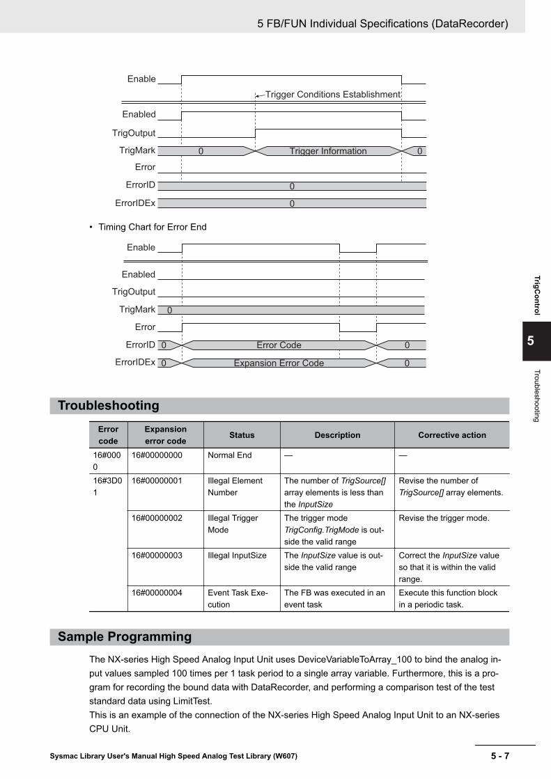
Enable
Enabled
Trigger Conditions Establishment
Trigger Information0 0
0
0
TrigOutput
TrigMark
Error
ErrorID
ErrorIDEx
• Timing Chart for Error End
Enable
Enabled
Error Code
Expansion Error Code
0
0
0
0
0
TrigOutput
TrigMark
Error
ErrorID
ErrorIDEx
TroubleshootingErrorcode
Expansionerror code Status Description Corrective action
16#0000
16#00000000 Normal End — —
16#3D01
16#00000001 Illegal ElementNumber
The number of TrigSource[]array elements is less thanthe InputSize
Revise the number ofTrigSource[] array elements.
16#00000002 Illegal TriggerMode
The trigger modeTrigConfig.TrigMode is out-side the valid range
Revise the trigger mode.
16#00000003 Illegal InputSize The InputSize value is out-side the valid range
Correct the InputSize valueso that it is within the validrange.
16#00000004 Event Task Exe-cution
The FB was executed in anevent task
Execute this function blockin a periodic task.
Sample ProgrammingThe NX-series High Speed Analog Input Unit uses DeviceVariableToArray_100 to bind the analog in-put values sampled 100 times per 1 task period to a single array variable. Furthermore, this is a pro-gram for recording the bound data with DataRecorder, and performing a comparison test of the teststandard data using LimitTest.This is an example of the connection of the NX-series High Speed Analog Input Unit to an NX-seriesCPU Unit.
5 FB/FUN Individual Specifications (DataRecorder)
5 - 7Sysmac Library User's Manual High Speed Analog Test Library (W607)
TrigControl
5
Troubleshooting

This sample programming consists of two POU, a program 0 for executing in the primary periodic task,and a program 1 for operation in periodic task 17.
Program 0 (Primary Periodic Task)• External Variables
Name Data typeConstant
Comment
NXBus_N2_NX_Unit_I_O_Data_Active_Status BOOLNXBus_N2_NX_Unit_Error_Status BOOLN2_Ch1_Analog_Input_Value_1_10 ARRAY[0..9] OF INTN2_Ch1_Analog_Input_Value_11_20 ARRAY[0..9] OF INTN2_Ch1_Analog_Input_Value_21_30 ARRAY[0..9] OF INTN2_Ch1_Analog_Input_Value_31_40 ARRAY[0..9] OF INTN2_Ch1_Analog_Input_Value_41_50 ARRAY[0..9] OF INTN2_Ch1_Analog_Input_Value_51_60 ARRAY[0..9] OF INTN2_Ch1_Analog_Input_Value_61_70 ARRAY[0..9] OF INTN2_Ch1_Analog_Input_Value_71_80 ARRAY[0..9] OF INTN2_Ch1_Analog_Input_Value_81_90 ARRAY[0..9] OF INTN2_Ch1_Analog_Input_Value_91_100 ARRAY[0..9] OF INTN2_Ch1_Number_of_Samplings UINTN2_Analog_Input_Time_Stamp ULINTCh1_Input_Array100 ARRAY[0..99] OF REAL Analog Input Value for
1 Task PeriodLogData ARRAY[0..4999] OF Omron-
Lib\DataRecorder\sLogDataRecorder Data Array
RecordEnd BOOLMasterReadEnd BOOL
• Internal Variables
Name Data typeDefault
AT
Retention
Constant
Comment
TrigControl_instance OmronLib\DataRecorder\Trig-Control
DataRecorder_instance OmronLib\DataRecorder\Data-Recorder
IO_Data_Is_Valid BOOLTrigConfig OmronLib\DataRecorder\sTrig-
ConfigTrigMark OmronLib\DataRecorder\sTrig-
MarkTrigOut BOOLDataBuf ARRAY[0..4999] OF OmronLib
\DataRecorder\sLogData
5 FB/FUN Individual Specifications (DataRecorder)
5 - 8 Sysmac Library User's Manual High Speed Analog Test Library (W607)

Name Data typeDefault
AT
Retention
Constant
Comment
RecordInfo OmronLib\DataRecorder\sRe-cordInfo
LogEnable BOOLSuccess_Concatenate BOOL
• Task SettingDeploy in the primary periodic task.
• LD Programa) Check that normal data is being received from the NX-series High Speed Analog Input Unit. If
connecting the NX-series High Speed Analog Input Unit to the EtherCAT slave terminal, refer to Sample Programming 2 on page 4 - 7.
b) Bind the analog input values for 1 task period to the single variable Ch1_Input_Array100[].
c) If executing the Program 1 (Periodic Task 17) on page 5 - 10 described below, and the masterdata CSV file readout is completed, the NX-series High Speed Analog Input Unit input value re-cord enters a trigger wait state. Set the trigger conditions in TrigConfig.• Trigger Conditions
TrigConfig.TrigMode=0 (Analog Level Trigger Mode)TrigMode.TrigSlope=FALSE (Startup)TrigMode.AnalogTrigLevel=REAL#100
5 FB/FUN Individual Specifications (DataRecorder)
5 - 9Sysmac Library User's Manual High Speed Analog Test Library (W607)
TrigControl
5
Sample Program
ming

d) If the trigger conditions are met, record the sampling data before trigger conditions were met withan input value of 1,000, and the sampling data after trigger conditions were met with a value of4,000 in LogData[].
Program 1 (Periodic Task 17)• External Variables
Name Data typeConstant
Comment
RecordEnd BOOLMasterReadEnd BOOLLogData ARRAY[0..4999] OF Omron-
Lib\DataRecorder\sLogData
• Internal Variables
Name Data typeDefault
AT
Retention
Constant
Comment
CSVToLogData_instance OmronLib\DataRecorder\CSVToLogData
LimitTest_instance OmronLib\DataRecorder\Lim-itTest
MasterData ARRAY[0..4999] OF OmronLib\DataRecorder\sLogData
FirstOutOfLimitPos UINTStart_P2 BOOL FA
LSE
If the value of this varia-ble is set to TRUE, exe-cute the program.
Pass BOOLCancel BOOL
• Task Setting
5 FB/FUN Individual Specifications (DataRecorder)
5 - 10 Sysmac Library User's Manual High Speed Analog Test Library (W607)
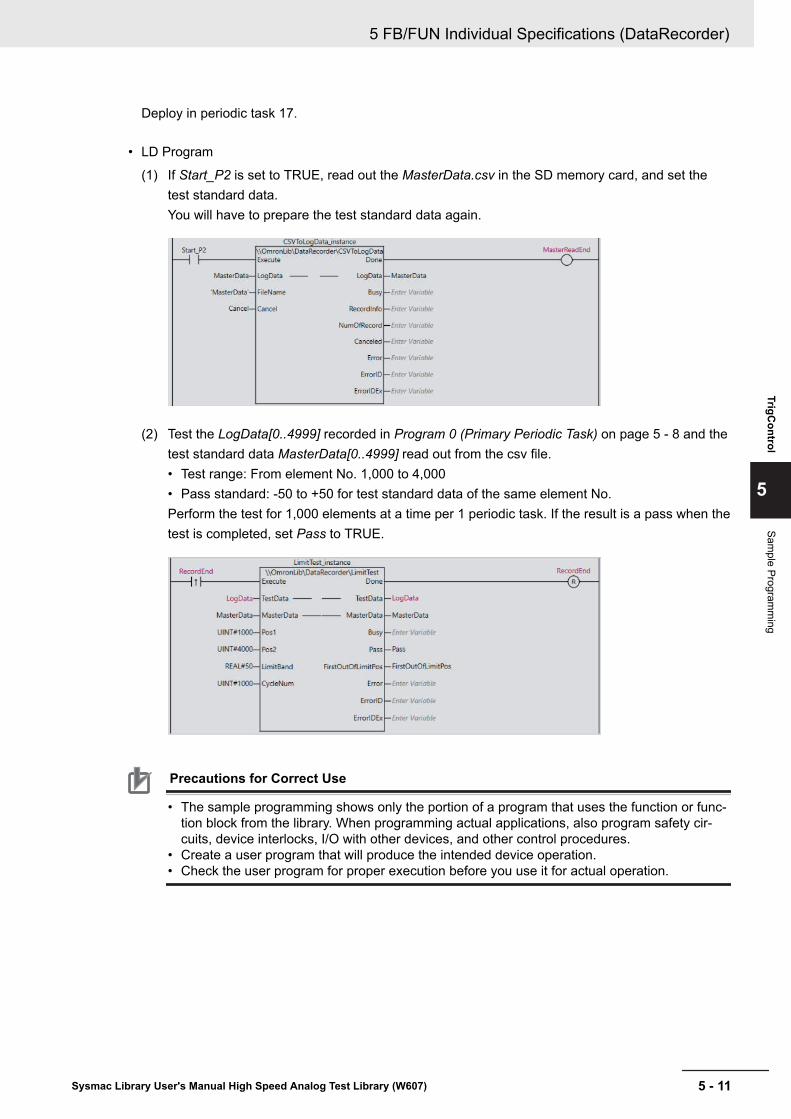
Deploy in periodic task 17.
• LD Program
(1) If Start_P2 is set to TRUE, read out the MasterData.csv in the SD memory card, and set thetest standard data.You will have to prepare the test standard data again.
(2) Test the LogData[0..4999] recorded in Program 0 (Primary Periodic Task) on page 5 - 8 and thetest standard data MasterData[0..4999] read out from the csv file.• Test range: From element No. 1,000 to 4,000• Pass standard: -50 to +50 for test standard data of the same element No.Perform the test for 1,000 elements at a time per 1 periodic task. If the result is a pass when thetest is completed, set Pass to TRUE.
Precautions for Correct Use
• The sample programming shows only the portion of a program that uses the function or func-tion block from the library. When programming actual applications, also program safety cir-cuits, device interlocks, I/O with other devices, and other control procedures.
• Create a user program that will produce the intended device operation.• Check the user program for proper execution before you use it for actual operation.
5 FB/FUN Individual Specifications (DataRecorder)
5 - 11Sysmac Library User's Manual High Speed Analog Test Library (W607)
TrigControl
5
Sample Program
ming

DataRecorderBind the data array for the specified number of elements to a single array variable for each task peri-od, and create the time series log data.
FB/FUNname Name FB/
FUN Graphic expression ST expression
DataRe-corder
Data Re-corder
FB\\OmronLib\DataRecorder\DataRecorder
DataRecorder_instance
Enable
InputData
LogData
DataBuf
TrigInput
TrigMark
TrigPos
InputDataTimeStamp
InputSize
TrigRdy
InputData
LogData
DataBuf
Busy
RecordEnd
RecordInfo
Error
ErrorID
ErrorIDEx
DataRecorder_in-stance(Enable,InputData,LogData,DataBuf,TrigInput,TrigMark,TrigPos,InputDataTimeS-tamp,InputSize,TrigRdy,Busy,RecordEnd,RecordInfo,Error,ErrorID,ErrorIDEx);
Library InformationItem Description
Library file name OmronLib_DataRecorder_Vx_x.slr (x shows the version)Namespace OmronLib\DataRecorderFunction block and func-tion number
00196
Source code Not Published
Input VariablesMeaning Data type Description Valid range Unit Default
Enable Execute BOOL TRUE: ExecuteFALSE: Do not execute
TRUE,FALSE
― FALSE
TrigInput Trigger in-put
BOOL Recording Start TriggerInput the BOOL type vari-ables, I/O data, or Trig-Control FB Trigger Output
TRUE,FALSE
― FALSE
TrigMark Trigger In-formation
OmronLib\DataRe-corder\sTrigMark
Input the TriggerInformation output by theTrigControl FB
― ― Pos=0Data=0
5 FB/FUN Individual Specifications (DataRecorder)
5 - 12 Sysmac Library User's Manual High Speed Analog Test Library (W607)

Meaning Data type Description Valid range Unit DefaultTrigPos Trigger Po-
sitionUINT During data recording,
specifies to which ele-ment No. in the LogData[]the data during trigger in-put will be recorded
Dependson datatype.
― 0
InputData-TimeStamp
Analog In-put TimeStamp
ULINT Inputs the Analog InputTime Stamp acquiredfrom the I/O data
Dependson datatype.
nsec 0
InputSize Number ofdata
UINT Inputs the Samplingnumber acquired from theI/O data
1 to 1000 ― 1
Output VariablesMeaning Data type Description Valid range Unit Default
TrigRdy Trigger in-put enabled
BOOL Set to TRUE when triggerinput can be accepted
TRUE,FALSE
― ―
Busy Now re-cording
BOOL Set to TRUE for the peri-od from when trigger inputis set to TRUE until re-cording is completed
TRUE,FALSE
― ―
RecordEnd Recordingcompleted
BOOL Set to TRUE when re-corded
TRUE,FALSE
― ―
RecordInfo Record In-formation
OmronLib\DataRe-corder\sRe-cordInfo
Outputs information suchas recording start time,trigger input time, etc.
― ― ―
Error Error BOOL TRUE: Error endFALSE: Normal end, exe-cution in progress, or exe-cution condition not met.
TRUE,FALSE
― ―
ErrorID Error Code WORD This is the error ID for anerror end.The value is 16#0 for anormal end.
*1 ― ―
ErrorIDEx ExpansionError Code
DWORD This is the error ID for anExpansion Unit HardwareError.The value is 16#0 for anormal end.
*1 ― ―
*1. Refer to Troubleshooting on page 5 - 17 for details.
Input-Output VariablesMeaning Data type Description Valid range Unit Default
InputDa-ta[]*1
Input Data ARRAY[*]OF REAL
Input the recording sourcedata array.
― ― ―
5 FB/FUN Individual Specifications (DataRecorder)
5 - 13Sysmac Library User's Manual High Speed Analog Test Library (W607)
DataR
ecorder
5
Output Variables

Meaning Data type Description Valid range Unit Default
LogData[]*2 Log Data ARRAY[*]OF Omron-Lib\DataRe-corder\sLogData
Input the recording desti-nation data array.The number of array ele-ments is the number ofrecords that can be re-corded
― ― ―
DataBuf[]*2 Input Buffer ARRAY[*]OF Omron-Lib\DataRe-corder\sLogData
Buffer that temporarilystores the recording data.The variables need to beassigned, but since this isintermediate data duringexecution of this FB, donot perform write or refer-encing.
― ― ―
*1. The number of array elements is arbitrary. However, the number of array elements must be equal to theInputSize or more. In addition, the array element start number can be either 0 or a number other than 0.
*2. The number of array elements is arbitrary. However, the number of array elements must be equal to theTrigPos or more. In addition, the array element start number can be either 0 or a number other than 0.
Structure• OmronLib\DataRecorder\sTrigMark
Refer to TrigControl on page 5 - 2 for the sTrigMark structure.• OmronLib\DataRecorder\sRecordInfo
Name Data type DescriptionStartDateTime DT Record the date and time for the first data item.EndDateTime DT Record the date and time for the final data item.
If the FB execution is ended during the recording, no recording is made.TriggerDateTime DT Record the date and time input by TrigInput.
The recording content may vary depending on the usage method. Referto Function on page 5 - 14 for details.
RecordNum UINT Record the number of data elements recorded in LogData[].TrigPos UINT Record the LogData[] element No. when TrigInput is set to TRUE.
• OmronLib\DataRecorder\sLogData
Name Data type DescriptionxTime ULINT Record the time stamp sampled by xData.xData REAL Record the input data.
FunctionWhile Enable is TRUE, record the element No. data specified in InputSize from InputData[] intoDataBuf[] for every task period.After Enable is set to TRUE, and if the data specified with TrigPos has finished being recorded inDataBuf[], set TrigRdy to TRUE.When TrigRdy is TRUE, TrigInput is set to TRUE, and when TrigRdy is FALSE, record the TrigPos andlater data in LogData[]. During this recording, set Busy to TRUE.When recording is completed, link the DataBuf[] data up to TrigPos to LogData[] and output it, andthen set RecordEnd to TRUE.
5 FB/FUN Individual Specifications (DataRecorder)
5 - 14 Sysmac Library User's Manual High Speed Analog Test Library (W607)

At the same time, output RecordInfo.When TrigRdy is FALSE, ignore TrigInput even if set to TRUE.If Enable is set to FALSE after recording is completed, end execution of this FB.After Enable is set to FALSE, retain RecordEnd and RecordInfo until Enable is again set to TRUE.
• Data Storage Method
(1) After Enable is set to TRUE and until TrigInput is set to TRUE, continue recording InputData[] toDataBuf[].
InputData[]
DataBuf[]
(2) When TrigInput is set to TRUE, record in order from TrigPos until the final element in LogData[].
InputData[]
TrigPos
LogData[]
(3) When recording up to the final element has ended, link the DataBuf[] data to the beginning ele-ment of LogData[] until the TrigPos -1 element in the new order, and complete the log data fromthe beginning to end elements of LogData[].
DataBuf[]
LogData[]
TrigPos
In the cases below, output TRUE to Error, and end the recording.a) When the number of InputData[] array elements is the InputSizeb) When the number of LogData[] or DataBuf[] array elements is less than the number of
InputData[] array elementsc) When TrigMark.Pos is an element No. outside the InputData[] array ranged) When TrigPos is outside the LogData[] or DataBuf[] rangee) When InputSize is 0, or at 1001 or moref) When the function block was executed in an event task
Perform the TrigInput and TrigMark input as shown below.
TrigInput TrigMarkWhen inputting arbitrary variables Variable is not assignedWhen inputting the TrigControl FB TrigOutput TrigControl FB TrigMark
5 FB/FUN Individual Specifications (DataRecorder)
5 - 15Sysmac Library User's Manual High Speed Analog Test Library (W607)
DataR
ecorder
5
Function
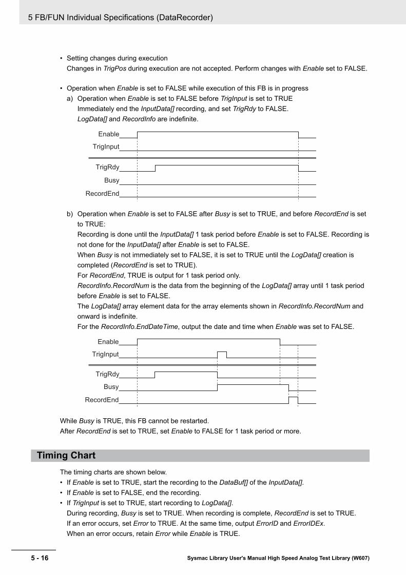
• Setting changes during executionChanges in TrigPos during execution are not accepted. Perform changes with Enable set to FALSE.
• Operation when Enable is set to FALSE while execution of this FB is in progressa) Operation when Enable is set to FALSE before TrigInput is set to TRUE
Immediately end the InputData[] recording, and set TrigRdy to FALSE.LogData[] and RecordInfo are indefinite.
Enable
TrigRdy
TrigInput
Busy
RecordEnd
b) Operation when Enable is set to FALSE after Busy is set to TRUE, and before RecordEnd is setto TRUE:Recording is done until the InputData[] 1 task period before Enable is set to FALSE. Recording isnot done for the InputData[] after Enable is set to FALSE.When Busy is not immediately set to FALSE, it is set to TRUE until the LogData[] creation iscompleted (RecordEnd is set to TRUE).For RecordEnd, TRUE is output for 1 task period only.RecordInfo.RecordNum is the data from the beginning of the LogData[] array until 1 task periodbefore Enable is set to FALSE.The LogData[] array element data for the array elements shown in RecordInfo.RecordNum andonward is indefinite.For the RecordInfo.EndDateTime, output the date and time when Enable was set to FALSE.
Enable
TrigRdy
TrigInput
Busy
RecordEnd
While Busy is TRUE, this FB cannot be restarted.After RecordEnd is set to TRUE, set Enable to FALSE for 1 task period or more.
Timing ChartThe timing charts are shown below.• If Enable is set to TRUE, start the recording to the DataBuf[] of the InputData[].• If Enable is set to FALSE, end the recording.• If TrigInput is set to TRUE, start recording to LogData[].
During recording, Busy is set to TRUE. When recording is complete, RecordEnd is set to TRUE.If an error occurs, set Error to TRUE. At the same time, output ErrorID and ErrorIDEx.When an error occurs, retain Error while Enable is TRUE.
5 FB/FUN Individual Specifications (DataRecorder)
5 - 16 Sysmac Library User's Manual High Speed Analog Test Library (W607)

After Enable is set to FALSE, retain ErrorID and ErrorIDEx until Enable is again set to TRUE.
• Timing Chart for Normal End
Enable
0
0
TrigRdy
Busy
TrigInput
RecordEnd
Error
ErrorID
ErrorIDEx
• Timing Chart for Error End
Enable
0 Error Code
Expansion Error Code0
0
0
TrigRdy
Busy
TrigInput
RecordEnd
Error
ErrorID
ErrorIDEx
TroubleshootingErrorcode
Expansionerror code Status Description Corrective action
16#0000
16#00000000 Normal End — —
16#3D02
16#00000001 Illegal InputData[]Element Number
The number of InputData[]array elements is less thanthe the InputSize
Revise the number ofInputData[] array elements.
16#00000002 Illegal LogData[],DataBuf[] ElementNumber
The number of LogData[] ar-ray or DataBuf[] array ele-ments is less than the num-ber of InputData[] array ele-ments
Revise the number ofLogData[] array or DataBuf[]array elements.
16#00000003 Illegal InputSize The InputSize value is out-side the valid range
Correct the InputSize valueso that it is within the validrange.
16#00000004 Illegal Trig-Mark.Pos
TrigMark.Pos exceeds theInputSize
Connect the TrigMark outputfor the TrigControl FB to theTrigMark for this FB.
5 FB/FUN Individual Specifications (DataRecorder)
5 - 17Sysmac Library User's Manual High Speed Analog Test Library (W607)
DataR
ecorder
5
Troubleshooting

Errorcode
Expansionerror code Status Description Corrective action
16#00000005 Illegal TrigPos The TrigPos is outside theLogData[] array or DataBuf[]array range
• Revise the TrigPos settingvalue.
• Revise the number ofLogData[] array orDataBuf[] array elements.
16#00000006 Event Task Exe-cution
The FB was executed in anevent task
Execute this function blockin a periodic task.
Sample ProgrammingRefer to Sample Programming on page 5 - 7.
5 FB/FUN Individual Specifications (DataRecorder)
5 - 18 Sysmac Library User's Manual High Speed Analog Test Library (W607)

LimitTestTest whether each element value in the data array targeted for tests is held to within the allowed rangefor test standard data.
FB/FUNname Name FB/
FUN Graphic expression ST expression
LimitTest UpperandLowerLimitTest
FB\\OmronLib\DataRecorder\LimitTestExecute
LimitTest_instance
Pos1
Pos2
LimitBand
CycleNum
TestData
MasterData
Done
Busy
Pass
FirstOutOfLimitPos
Error
ErrorID
ErrorIDEx
TestData
MasterData
LimitTest_instance(Execute,TestData,MasterData,Pos1,Pos2,LimitBand,CycleNum,Done,Busy,Pass,FirstOutOfLimitPos,Error,ErrorID,ErrorIDEx);
Library InformationItem Description
Library file name OmronLib_DataRecorder_Vx_x.slr (x shows the version)Namespace OmronLib\DataRecorderFunction block and func-tion number
00197
Source code Not Published
Input VariablesMeaning Data type Description Valid range Unit Default
Execute Execute BOOL TRUE: ExecuteFALSE: Do not execute
TRUE,FALSE
― FALSE
Pos1 Test RangeElement 1
UINT Specifies the start ele-ment No. in the test targetrange
Dependson datatype.
― 0
Pos2 Test RangeElement 2
UINT Specifies the end elementNo. in the test targetrange
Dependson datatype.
― 0
LimitBand ToleranceValue
REAL Specifies the tolerancerange
0 andgreater
― 0.0
5 FB/FUN Individual Specifications (DataRecorder)
5 - 19Sysmac Library User's Manual High Speed Analog Test Library (W607)
LimitTest
5
Library Information

Meaning Data type Description Valid range Unit DefaultCycleNum Number of
ElementsTested in 1Period
UINT Specifies the number ofelements tested in 1 taskperiodIf 0 is specified, processthe test target range ele-ment for 1 task period
Dependson datatype.
― 0
Output VariablesMeaning Data type Description Valid range Unit Default
Done Done BOOL TRUE: Normal endFALSE: Error end, execu-tion in progress, or execu-tion condition not met.
TRUE,FALSE
― ―
Busy Executing BOOL TRUE: Executing.FALSE: Not executing.
TRUE,FALSE
― ―
Pass Test Pass BOOL TRUE: PassFALSE: Non-passing ele-ments exist
TRUE,FALSE
― ―
FirstOutO-fLimitPos
First non-passing el-ement No.
UINT Element No. of first ele-ment discovered to be outof the allowed range
Dependson datatype.
― ―
Error Error BOOL TRUE: Error endFALSE: Normal end, exe-cution in progress, or exe-cution condition not met.
TRUE,FALSE
― ―
ErrorID Error Code WORD This is the error ID for anerror end.The value is 16#0 for anormal end.
*1 ― ―
ErrorIDEx ExpansionError Code
DWORD This is the error ID for anExpansion Unit HardwareError.The value is 16#0 for anormal end.
*1 ― ―
*1. Refer to Troubleshooting on page 5 - 23 for details.
Input-Output VariablesMeaning Data type Description Valid range Unit Default
TestData[]*1 Test TargetData
ARRAY[*]OF Omron-Lib\DataRe-corder\sLogData
Specifies the data arraytargeted for testing
― ― ―
5 FB/FUN Individual Specifications (DataRecorder)
5 - 20 Sysmac Library User's Manual High Speed Analog Test Library (W607)

Meaning Data type Description Valid range Unit DefaultMasterDa-ta[]*2
Test Stand-ard Data
ARRAY[*]OF Omron-Lib\DataRe-corder\sLogData
Specifies the data arrayforming the test standard
― ― ―
*1. The number of array elements is arbitrary. In addition, the array element start number can be either 0 or anumber other than 0.
*2. The number of array elements is arbitrary. However, it must have the same number of elements asTestData[]. In addition, the array element start number can be either 0 or a number other than 0.
Structure• OmronLib\DataRecorder\sLogData
Refer to TrigControl on page 5 - 2.
FunctionTest whether each TestData[] element is within the MasterData[] ± LimitBand range.The TestData[] test range is elements specified between Pos1 and Pos2. Do not test elements outsideof the range.With the startup of Execute, test each TestData[] element in order from Pos1.When all TestData[] elements from Pos1 to Pos2 are within the MasterData[] ± LimitBand range, setPass to TRUE, and output 65535 to FirstOutOfLimitPos.If testing elements outside the allowed range during testing, do not perform the tests up to Pos2.When elements outside the range are detected, set Busy to FALSE and Done to TRUE. InFirstOutOfLimitPos, output the element No. where the value outside the allowed range was first de-tected as a relative value from the beginning of the array.
MasterData[ ]
TestData[ ]
LimitBand
LimitBand
Pos1 Pos2
FirstOutOfLimitPos
The pass judgment standards are as shown below.MasterData[x] - LimitBand ≤ TestData[x] ≤ MasterData[x] + LimitBand
5 FB/FUN Individual Specifications (DataRecorder)
5 - 21Sysmac Library User's Manual High Speed Analog Test Library (W607)
LimitTest
5
Structure

In the cases below, output TRUE to Error, and end the test.• When TestData[] and MasterData[] array element numbers do not match• When the LimitBand value is a negative number, non-number, or ∞• When Pos1 and Pos2 are outside the TestData[] or MasterData[] array range
Pos1 and Pos2 specification methodSpecify the Pos1 and Pos2 values as relative values from the first element.Example: For TestData [10..100], if Pos1 is 0, it indicates TestData[10].
• Setting changes during executionMultiple startup of this FB, and changes while execution is in progress for Pos1, Pos2, LimitBand,and CycleNum are not accepted.
• CycleNum specificationWith specification of the number of test elements per 1 task period in CycleNum, you can adjust theexecution time per 1 task period of the FB and the time until test completion.If a small value is specified, the execution time per 1 task period is shortened, and the executionperiod until test completion is lengthened.If a large value is specified, the time until test completion is shortened, and the FB execution timeper 1 task period is lengthened.Perform the adjustment with consideration for the number of TestData[] array elements, the task pe-riod when deploying this FB, and the load from programs other than this FB that are operating.
Timing ChartThe timing charts are shown below.• With the startup of Execute, set Busy to TRUE.• If the judgment for all elements is completed, set Done to TRUE, and output the test results to Pass
and FirstOutOfLimitPos.Retain Done until Execute is set to FALSE.After Execute is set to FALSE, retain Pass and FirstOutOfLimitPos until Execute is again set toTRUE.
• If an error occurs, set Error to TRUE. At the same time, output ErrorID and ErrorIDEx.Retain Error until Execute is set to FALSE.After Execute is set to FALSE, retain ErrorID and ErrorIDEx until Execute is again set to TRUE.
• If Execute is set to FALSE while Busy is TRUE, then Done and Error are TRUE only for 1 periodafter the test end.
• Timing Chart for Normal End
5 FB/FUN Individual Specifications (DataRecorder)
5 - 22 Sysmac Library User's Manual High Speed Analog Test Library (W607)

FirstOutOfLimitPos
Execute
Busy
Pass
0
0
Error
ErrorID
ErrorIDEx
Done
0 0Element No. 655350
• Timing Chart for Error End
0
0
Error Code
Expansion Error Code
Execute
Busy
Pass
FirstOutOfLimitPos 0
0
0
Error
ErrorID
ErrorIDEx
Done
Error Code
Expansion Error Code
Precautions for Correct UseExecution of this function block will be continued until processing is ended even if Execute changes toFALSE or the execution time exceeds the task period.The value of Done changes to TRUE when processing is ended. Use this to confirm normal ending ofprocessing.
TroubleshootingErrorcode
Expansionerror code Status Description Corrective action
16#0000
16#00000000 Normal End — —
16#3D03
16#00000001 Array ElementMismatch
The TestData[] andMasterData[] array elementnumbers do not match
Revise the TestData[] andMasterData[] array elementnumber.
16#00000002 Illegal LimitBand The LimitBand value is out-side the valid range
Correct the LimitBand valueso that it is within the validrange.
16#00000003 Illegal Test Range Pos1 and Pos2 are outsidethe TestData[] orMasterData[] range
Revise the Pos1 and Pos2values.
5 FB/FUN Individual Specifications (DataRecorder)
5 - 23Sysmac Library User's Manual High Speed Analog Test Library (W607)
LimitTest
5
Precautions for Correct U
se

Sample ProgrammingRefer to Sample Programming on page 5 - 7.
5 FB/FUN Individual Specifications (DataRecorder)
5 - 24 Sysmac Library User's Manual High Speed Analog Test Library (W607)
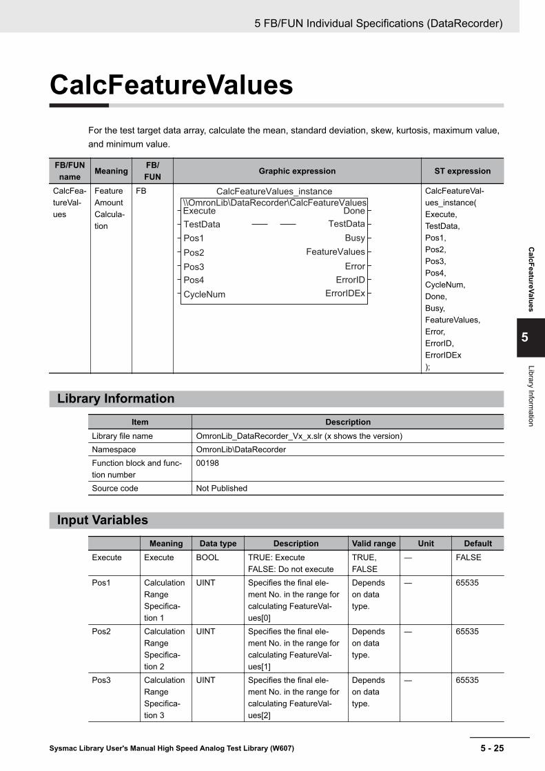
CalcFeatureValuesFor the test target data array, calculate the mean, standard deviation, skew, kurtosis, maximum value,and minimum value.
FB/FUNname Meaning FB/
FUN Graphic expression ST expression
CalcFea-tureVal-ues
FeatureAmountCalcula-tion
FB\\OmronLib\DataRecorder\CalcFeatureValuesExecute
CalcFeatureValues_instance
Pos1
Pos2
Pos3
Pos4
CycleNum
TestData
Done
Busy
FeatureValues
Error
ErrorID
ErrorIDEx
TestData
CalcFeatureVal-ues_instance(Execute,TestData,Pos1,Pos2,Pos3,Pos4,CycleNum,Done,Busy,FeatureValues,Error,ErrorID,ErrorIDEx);
Library InformationItem Description
Library file name OmronLib_DataRecorder_Vx_x.slr (x shows the version)Namespace OmronLib\DataRecorderFunction block and func-tion number
00198
Source code Not Published
Input VariablesMeaning Data type Description Valid range Unit Default
Execute Execute BOOL TRUE: ExecuteFALSE: Do not execute
TRUE,FALSE
― FALSE
Pos1 CalculationRangeSpecifica-tion 1
UINT Specifies the final ele-ment No. in the range forcalculating FeatureVal-ues[0]
Dependson datatype.
― 65535
Pos2 CalculationRangeSpecifica-tion 2
UINT Specifies the final ele-ment No. in the range forcalculating FeatureVal-ues[1]
Dependson datatype.
― 65535
Pos3 CalculationRangeSpecifica-tion 3
UINT Specifies the final ele-ment No. in the range forcalculating FeatureVal-ues[2]
Dependson datatype.
― 65535
5 FB/FUN Individual Specifications (DataRecorder)
5 - 25Sysmac Library User's Manual High Speed Analog Test Library (W607)
CalcFeatureValues
5
Library Information

Meaning Data type Description Valid range Unit DefaultPos4 Calculation
RangeSpecifica-tion 4
UINT Specifies the final ele-ment No. in the range forcalculating FeatureVal-ues[3]
Dependson datatype.
― 65535
CycleNum Number ofElementsCalculatedin 1 Period
UINT Specifies the number ofelements calculated in 1task period.If 0 is specified, processthe calculation targetrange element for 1 taskperiod
Dependson datatype.
― 0
Output VariablesMeaning Data type Description Valid range Unit Default
Done Done BOOL TRUE: Normal endFALSE: Error end, execu-tion in progress, or execu-tion condition not met.
TRUE,FALSE
― ―
Busy Executing BOOL TRUE: Executing.FALSE: Not executing.
TRUE,FALSE
― ―
FeatureVal-ues[]
FeatureAmount
AR-RAY[0..3]OF Omron-Lib\DataRe-corder\sFeature-Value
Feature Amount Calcula-tion Result
― ― ―
Error Error BOOL TRUE: Error endFALSE: Normal end, exe-cution in progress, or exe-cution condition not met.
TRUE,FALSE
― ―
ErrorID Error Code WORD This is the error ID for anerror end.The value is 16#0 for anormal end.
*1 ― ―
ErrorIDEx ExpansionError Code
DWORD This is the error ID for anExpansion Unit HardwareError.The value is 16#0 for anormal end.
*1 ― ―
*1. Refer to Troubleshooting on page 5 - 29 for details.
5 FB/FUN Individual Specifications (DataRecorder)
5 - 26 Sysmac Library User's Manual High Speed Analog Test Library (W607)

Input-Output VariablesMeaning Data type Description Valid range Unit Default
TestData[]*1 CalculationTarget Data
ARRAY[*]OF Omron-Lib\DataRe-corder\sLogData
Specifies the array target-ed for calculation of fea-ture amounts
― ― ―
*1. The number of array elements is arbitrary. In addition, the array element start number can be either 0 or anumber other than 0.
Structure• OmronLib\DataRecorder\sFeatureValue
Name Data type DescriptionxMean REAL Mean ValuexSD REAL Standard DeviationxSkewness REAL SkewxKurtosis REAL KurtosisxMax REAL Maximum ValuexMin REAL Minimum Value
• OmronLib\DataRecorder\sLogDataRefer to DataRecorder on page 5 - 12.
Function
With the startup of Execute, calculate the mean value, standard deviation, skew, kurtosis, maximumvalue, and minimum value of the TestData[] elements within the range specified in Pos1, Pos2, Pos3,and Pos4, and store the calculation results in FeatureValues[].
• Calculation range specificationItems related to the calculation range and calculation result storage location are shown below.You can perform calculation even if the four calculation range elements are overlapping. In addition,you can perform calculation even if the start element and end element sizes are reversed.
Calculation RangeCalculation Result Storage Location
Start Element Final ElementTestData[Array Start] TestData[Pos1]*1 FeatureValues[0]
TestData[Pos1+1]*2 TestData[Pos2]*1 FeatureValues[1]
TestData[Pos2+1]*2 TestData[Pos3]*1 FeatureValues[2]
TestData[Pos3+1]*2 TestData[Pos4]*1 FeatureValues[3]
*1. If values exceeding 65535 or the number of TestData[] elements are set to Pos1, Pos2, Pos3, or Pos4,the calculation range and later calculation ranges become invalid, and all calculation results are stored as0.
*2. If Pos1+1, Pos2+1, and Pos3+1 are outside the TestData[] range, the calculation range and later calcula-tion ranges become invalid, and all calculation results are stored as 0.
5 FB/FUN Individual Specifications (DataRecorder)
5 - 27Sysmac Library User's Manual High Speed Analog Test Library (W607)
CalcFeatureValues
5
Input-Output Variables

Pos1 Pos2 Pos3 Pos4 FeatureVal-ues [0]
FeatureVal-ues [1]
Feature-Values [2]
Feature-Values
[3]65535 Invalid Invalid Invalid 0 0 0 0Valid Value 65535 Invalid Invalid Calculation
Result0 0 0
Valid Value Valid Value 65535 Invalid CalculationResult
CalculationResult
0 0
Valid Value Valid Value Valid Value 65535 CalculationResult
CalculationResult
CalculationResult
0
Valid Value Valid Value Valid Value Valid Val-ue
CalculationResult
CalculationResult
CalculationResult
Calcula-tion Re-sult
• Pos1, Pos2, Pos3, and Pos4 specification methodSpecify Pos1, Pos2, Pos3, and Pos4 as relative values from the beginning of the TestData[] array.Example: For TestData[10..100], if Pos1 is 0, it indicates TestData[10].
• Setting changes during executionMultiple startups of this FB, and changes while execution is in progress for Pos1, Pos2, Pos3, Pos4,and CycleNum are not accepted.
• CycleNum specificationWith specification of the number of calculation elements per 1 task period in CycleNum, you can ad-just the execution time per 1 task period of the FB and the time until calculation completion.If a small value is specified, the execution time per 1 task period is shortened, and the executionperiod until calculation completion is lengthened.If a large value is specified, the time until calculation completion is shortened, and the FB executiontime per 1 task period is lengthened.Perform the adjustment with consideration for the number of TestData[] array elements, the task pe-riod when deploying this FB, and the load from programs other than this FB that are operating.
Timing ChartThe timing charts are shown below.• With the startup of Execute, set Busy to TRUE.• If the calculation of all feature amounts is completed, set Done to TRUE, and output the calculation
result to FeatureValues[].Retain Done until Execute is set to FALSE.After Execute is set to FALSE, retain FeatureValues[] until Execute is again set to TRUE.
• If Busy is set to FALSE while Busy is TRUE, then Done is TRUE only for 1 period after the calcula-tion end.
5 FB/FUN Individual Specifications (DataRecorder)
5 - 28 Sysmac Library User's Manual High Speed Analog Test Library (W607)

Execute
Busy
FeatureValues[] 0 0 0
0
0
Error
ErrorID
ErrorIDEx
Done
Calculation ResultCalculation Result
Precautions for Correct UseExecution of this function block will be continued until processing is ended even if Execute changes toFALSE or the execution time exceeds the task period.The value of Done changes to TRUE when processing is ended. Use this to confirm normal ending ofprocessing.
TroubleshootingErrorcode
Expansionerror code Status Description Corrective action
16#0000
16#00000000 Normal End — —
Sample ProgrammingThe NX-series High Speed Analog Input Unit uses DeviceVariableToArray_100 to bind the analog in-put values sampled 100 times per 1 task period to a single array variable. Furthermore, this is a pro-gram for recording the bound data with DataRecorder, and performing a comparison test of the teststandard data using LimitTest.This is an example of the connection of the NX-series High Speed Analog Input Unit to an NX-seriesCPU Unit.This sample programming consists of two POU, a program 0 for executing in the primary periodic task,and a program 1 for operation in periodic task 17.
Program 0 (Primary Periodic Task)• External Variables
Name Data typeConstant
Comment
NXBus_N2_NX_Unit_I_O_Data_Active_Status BOOLNXBus_N2_NX_Unit_Error_Status BOOLN2_Ch1_Analog_Input_Value_1_10 ARRAY[0..9] OF INTN2_Ch1_Analog_Input_Value_11_20 ARRAY[0..9] OF INTN2_Ch1_Analog_Input_Value_21_30 ARRAY[0..9] OF INT
5 FB/FUN Individual Specifications (DataRecorder)
5 - 29Sysmac Library User's Manual High Speed Analog Test Library (W607)
CalcFeatureValues
5
Precautions for Correct U
se

Name Data typeConstant
Comment
N2_Ch1_Analog_Input_Value_31_40 ARRAY[0..9] OF INTN2_Ch1_Analog_Input_Value_41_50 ARRAY[0..9] OF INTN2_Ch1_Analog_Input_Value_51_60 ARRAY[0..9] OF INTN2_Ch1_Analog_Input_Value_61_70 ARRAY[0..9] OF INTN2_Ch1_Analog_Input_Value_71_80 ARRAY[0..9] OF INTN2_Ch1_Analog_Input_Value_81_90 ARRAY[0..9] OF INTN2_Ch1_Analog_Input_Value_91_100 ARRAY[0..9] OF INTN2_Ch1_Number_of_Samplings UINTN2_Analog_Input_Time_Stamp ULINTN2_Ch1_Trigger_Input_Time_Stamp ULINTN2_Ch1_Trigger_Input BOOLCh1_Input_Array100 ARRAY[0..99] OF REAL Analog Input Value for
1 Task PeriodLogData ARRAY[0..4999] OF Omron-
Lib\DataRecorder\sLogDataRecorder Data Array
RecordInfo OmronLib\DataRecorder\sRecordInfo
RecordEnd BOOL
• Internal Variables
Name Data type Default AT
Retention
Constant
Comment
TrigControl_instance OmronLib\DataRecorder\TrigControl
DataRecorder_instance OmronLib\DataRecorder\DataRecorder
IO_Data_Is_Valid BOOLTrigConfig OmronLib\DataRecorder
\sTrigConfigTrigMark OmronLib\DataRecorder
\sTrigMarkTrigOut BOOLDataBuf ARRAY[0..4999] OF Om-
ronLib\DataRecorder\sLogData
Start_P3 BOOL FALSE If the value of thisvariable is set toTRUE, execute theprogram.
LogEnable BOOLSuccess_Concatenate BOOL
• Task SettingDeploy in the primary periodic task.
5 FB/FUN Individual Specifications (DataRecorder)
5 - 30 Sysmac Library User's Manual High Speed Analog Test Library (W607)

• LD Program
(1) Check that normal data is being received from the NX-series High Speed Analog Input Unit. Ifconnecting the NX-series High Speed Analog Input Unit to the EtherCAT slave terminal, refer to Sample Programming 2 on page 4 - 7.
(2) Bind the analog input values for 1 task period to the single variable Ch1_Input_Array100[].
(3) If Start_P3 is set to TRUE, the NX-series High Speed Analog Input Unit input value record en-ters a trigger wait state. Set the trigger conditions in TrigConfig.• Trigger Conditions
TrigConfig.TrigMode=2 (Time Stamp Trigger Mode)TrigInput=N2_Ch1_Trigger_Input (Ch1 Trigger Input of NX-series High Speed Analog InputUnit)
(4) If the trigger conditions are met, record the 5,000 sampling data from trigger establishment inLogData[].
5 FB/FUN Individual Specifications (DataRecorder)
5 - 31Sysmac Library User's Manual High Speed Analog Test Library (W607)
CalcFeatureValues
5
Sample Program
ming

Program 1 (Periodic Task 17)• External Variables
Name Data typeConstant
Comment
RecordEnd BOOLRecordInfo OmronLib\DataRecorder
\sRecordInfoLogData ARRAY[0..4999] OF Omron-
Lib\DataRecorder\sLogData
• Internal Variables
Name Data typeDefault
AT
Retention
Constant
Comment
CalcFeatureValues_in-stance
OmronLib\DataRecorder\Calc-FeatureValues
LogDataToCSV_instance OmronLib\DataRecorder\Log-DataToCSV
FeatureValues ARRAY[0..3] OF OmronLib\Da-taRecorder\sFeatureValue
Cancel BOOL
• Task SettingDeploy in periodic task 17.
• LD Program
(1) When the recording of the data executed in Program 0 (Primary Periodic Task) on page 5 - 29is completed, and RecordEnd is set to TRUE, calculate the recording data LogData[] featureamount for each data interval specified in Pos1 to Pos4.
5 FB/FUN Individual Specifications (DataRecorder)
5 - 32 Sysmac Library User's Manual High Speed Analog Test Library (W607)

When you complete the feature amount calculation, write the LogData[] data to an SD memorycard with the file name Data.csv.
In FeatureVlues[], store the following feature amounts.
.xMean .xSD .xSkew-ness
.xKurto-sis .xMax .xMin Remarks
Featur-eVlues[0]
Mean Val-ue
StandardDeviation
Skew Kurtosis MaximumValue
MinimumValue
LogData[0..1000]feature amount
Featur-eVlues[1]
Mean Val-ue
StandardDeviation
Skew Kurtosis MaximumValue
MinimumValue
LogDa-ta[1001..2000] fea-ture amount
Featur-eVlues[2]
Mean Val-ue
StandardDeviation
Skew Kurtosis MaximumValue
MinimumValue
LogDa-ta[2001..3000] fea-ture amount
Featur-eVlues[3]
Mean Val-ue
StandardDeviation
Skew Kurtosis MaximumValue
MinimumValue
LogDa-ta[3001..4000] fea-ture amount
Precautions for Correct Use
• The sample programming shows only the portion of a program that uses the function or func-tion block from the library. When programming actual applications, also program safety cir-cuits, device interlocks, I/O with other devices, and other control procedures.
• Create a user program that will produce the intended device operation.• Check the user program for proper execution before you use it for actual operation.
5 FB/FUN Individual Specifications (DataRecorder)
5 - 33Sysmac Library User's Manual High Speed Analog Test Library (W607)
CalcFeatureValues
5
Sample Program
ming

LogDataToCSVOutput the log data created in the DataRecorder FB as a CSV type file (*.csv) to an SD memory card.
FB/FUNname Name FB/
FUN Graphic expression ST expression
LogDa-taToCSV
Log DataCSV FileWrite
FB\\OmronLib\DataRecorder\LogDataToCSVExecute
LogDataToCSV_instance
FileName
WriteLineNum
Cancel
LogData
RecordInfo
Done
Busy
Canceled
Error
ErrorID
ErrorIDEx
LogData
LogDataToCSV_in-stance(Execute,LogData,RecordInfo,FileName,WriteLineNum,Cancel,Done,Busy,Canceled,Error,ErrorID,ErrorIDEx);
Library InformationItem Description
Library file name OmronLib_DataRecorder_Vx_x.slr (x shows the version)Namespace OmronLib\DataRecorderFunction block and func-tion number
00199
Source code Not Published
Input VariablesMeaning Data type Description Valid range Unit Default
Execute Execute BOOL TRUE: ExecuteFALSE: Do not execute
TRUE,FALSE
― FALSE
RecordInfo Record In-formation
OmronLib\DataRe-corder\sRe-cordInfo
Inputs record informationoutput by the DataRecor-der FB
― ― ―
FileName File Name STRING[66]
File name of CSV file towrite.Can specify items includ-ing directory
Maximum66 bytes(65 single-byte alpha-numericcharactersplus the fi-nal NULLcharacter)
― ‘’
5 FB/FUN Individual Specifications (DataRecorder)
5 - 34 Sysmac Library User's Manual High Speed Analog Test Library (W607)

Meaning Data type Description Valid range Unit DefaultWriteLine-Num
Number ofLines Out-put in 1 Pe-riod
USINT Specifies the number oflines written in each exe-cution period with this pa-rameter
1 to 255 ― 1
Cancel Cancel BOOL TRUE: Cancels the filewrite
TRUE,FALSE
― FALSE
Output VariablesMeaning Data type Description Valid range Unit Default
Done Done BOOL TRUE: Normal endFALSE: Error end, execu-tion in progress, or execu-tion condition not met.
TRUE,FALSE
― ―
Busy Executing BOOL TRUE: Executing.FALSE: Not executing.
TRUE,FALSE
― ―
Canceled Cancel End BOOL TRUE: Canceled.FALSE: Not canceled.
TRUE,FALSE
― ―
Error Error BOOL TRUE: Error endFALSE: Normal end, exe-cution in progress, or exe-cution condition not met.
TRUE,FALSE
― ―
ErrorID Error Code WORD This is the error ID for anerror end.The value is 16#0 for anormal end.
*1 ― ―
ErrorIDEx ExpansionError Code
DWORD This is the error ID for anExpansion Unit HardwareError.The value is 16#0 for anormal end.
*1 ― ―
*1. Refer to Troubleshooting on page 5 - 39 for details.
Input-Output VariablesMeaning Data type Description Valid range Unit Default
LogData[]*1 Log Data ARRAY[*]OF Omron-Lib\DataRe-corder\sLogData
Specifies log data read-out to the CSV file
― ― ―
*1. The number of array elements is arbitrary. In addition, the array element start number can be either 0 or anumber other than 0.
Structure• OmronLib\DataRecorder\sLogData
Refer to DataRecorder on page 5 - 12.• OmronLib\DataRecorder\sRecordInfo
Refer to DataRecorder on page 5 - 12.
5 FB/FUN Individual Specifications (DataRecorder)
5 - 35Sysmac Library User's Manual High Speed Analog Test Library (W607)
LogDataToC
SV
5
Output Variables
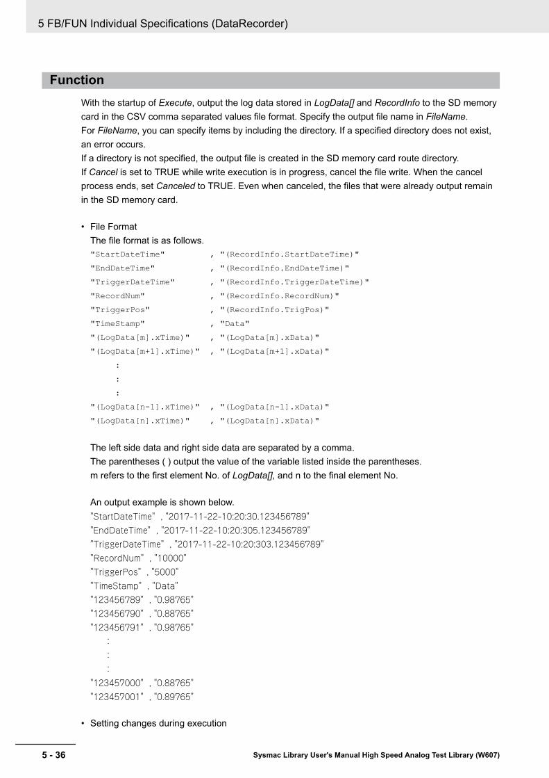
FunctionWith the startup of Execute, output the log data stored in LogData[] and RecordInfo to the SD memorycard in the CSV comma separated values file format. Specify the output file name in FileName.For FileName, you can specify items by including the directory. If a specified directory does not exist,an error occurs.If a directory is not specified, the output file is created in the SD memory card route directory.If Cancel is set to TRUE while write execution is in progress, cancel the file write. When the cancelprocess ends, set Canceled to TRUE. Even when canceled, the files that were already output remainin the SD memory card.
• File FormatThe file format is as follows."StartDateTime" , "(RecordInfo.StartDateTime)""EndDateTime" , "(RecordInfo.EndDateTime)""TriggerDateTime" , "(RecordInfo.TriggerDateTime)""RecordNum" , "(RecordInfo.RecordNum)""TriggerPos" , "(RecordInfo.TrigPos)""TimeStamp" , "Data""(LogData[m].xTime)" , "(LogData[m].xData)""(LogData[m+1].xTime)" , "(LogData[m+1].xData)" : : :"(LogData[n-1].xTime)" , "(LogData[n-1].xData)""(LogData[n].xTime)" , "(LogData[n].xData)"
The left side data and right side data are separated by a comma.The parentheses ( ) output the value of the variable listed inside the parentheses.m refers to the first element No. of LogData[], and n to the final element No.
An output example is shown below."StartDateTime" , "2017-11-22-10:20:30.123456789""EndDateTime" , "2017-11-22-10:20:305.123456789""TriggerDateTime" , "2017-11-22-10:20:303.123456789""RecordNum" , "10000""TriggerPos" , "5000""TimeStamp" , "Data""123456789" , "0.98765""123456790" , "0.88765""123456791" , "0.98765" : : :"123457000" , "0.88765""123457001" , "0.89765"
• Setting changes during execution
5 FB/FUN Individual Specifications (DataRecorder)
5 - 36 Sysmac Library User's Manual High Speed Analog Test Library (W607)
Multiple startups of this FB and changes in the FileName and WriteLineNum are not accepted.
• WriteLineNum specificationWith specification of the number of output lines per 1 task period in WriteLineNum, you can adjustthe execution time per 1 task period of the FB, and the time until output end.If a small value is specified, the execution time per 1 task period is shortened, and the executionperiod until calculation completion is lengthened.If a large value is specified, the time until calculation completion is shortened, and the FB executiontime per 1 task period is lengthened.Perform the adjustment with consideration for the number of LogData[] array elements, the task pe-riod when deploying this FB, and the load from programs other than this FB that are operating.However, in this FB, the limit of 1 KB per 1 task period is set as the upper limit.
Additional Information• For RecordInfo.StartDateTime, RecordInfo.EndDateTime, and RecordInfo.TriggerDateTime, use the
DtToString command to convert to text strings and write. Refer to the NJ/NX-series InstructionsReference Manual (Cat. No. W508) for details on the DtToString command.
• For LogData[].xData, use the RealToFormatString command and convert to a text string.For the number of digits, the overall is eight and the fractional part is six.Refer to the NJ/NX-series Instructions Reference Manual (Cat. No. W508) for details on the RealTo-FormatString command.
Timing ChartThe timing charts are shown below.• With the startup of Execute, set Busy to TRUE.• When the write of all the log data is completed, set Done to TRUE.
Retain Done until Execute is set to FALSE.• If Cancel is set to TRUE while write execution is in progress, cancel the file write, and set Canceled
to TRUE.• If an error occurs, set Error to TRUE. At the same time, output ErrorID and ErrorIDEx.
Retain Error and Canceled until Execute is set to FALSE.After Execute is set to FALSE, retain ErrorID and ErrorIDEx until Execute is again set to TRUE.
• If Execute is set to FALSE while Busy is TRUE, then Done, Canceled, and Error are TRUE for only1 period after the end of write/cancel processing.
• Timing Chart for Normal End
5 FB/FUN Individual Specifications (DataRecorder)
5 - 37Sysmac Library User's Manual High Speed Analog Test Library (W607)
LogDataToC
SV
5
Additional Information

Execute
Busy
Cancel
Canceled
0
0
Error
ErrorID
ErrorIDEx
Done
• Timing Chart for Cancel End
Execute
Busy
Cancel
Canceled
0
0
Error
ErrorID
ErrorIDEx
Done
• Timing Chart for Error End
Execute
Busy
Cancel
Canceled
0 Error Code
Expansion Error Code0
0
0
Error
ErrorID
ErrorIDEx
Done
Error Code
Expansion Error Code
Precautions for Correct Use• Execution of this function block will be continued until processing is ended even if the value of
Execute changes to FALSE or the execution time exceeds the task period. The value of Donechanges to TRUE when processing is ended. Use this to confirm normal ending of processing.
• While execution of this FB is in progress, do not access a write target file from another FB.
5 FB/FUN Individual Specifications (DataRecorder)
5 - 38 Sysmac Library User's Manual High Speed Analog Test Library (W607)

Troubleshooting
Error code Expansionerror code Status Description Corrective action
16#0000 16#00000000 Normal End — —16#0400 16#00000000 Input Value Out of Range The file name
specified withFileName containsone or more char-acters that cannotbe used
Set FileName cor-rectly.
The directoryname specifiedwith FileName istoo long
Check the lengthof the text stringsspecified withFileName so that itis within the validrange.
16#1400 16#00000000 SD Memory Card AccessFailure
This occurs when this FB is used in theNJ/NX-series CPU Unit.Refer to the NJ/NX-seriesTroubleshooting Manual (Cat. No.W503).
16#1401 16#00000000 SD Memory Card Write-protected
16#1402 16#00000000 SD Memory Card Insuffi-cient Capacity
16#1404 16#00000000 Too Many Files/Directo-ries
16#1405 16#00000000 File Already in Use16#140A 16#00000000 Write Access Denied16#140B 16#00000000 Too Many Files Open16#140D 16#00000000 File or Directory Name Is
Too Long16#140E 16#00000000 SD Memory Card Access
Failed16#4400 16#00000000 Shared Folder Cannot Be
UsedThis occurs when this FB is used in theNY-series Industrial PC.Refer to the NY-series TroubleshootingManual (SBCA-438).
16#4402 16#00000000 Insufficient Shared FolderCapacity
16#4404 16#00000000 Too Many Files/Directo-ries
16#440D 16#00000000 File or Directory Name IsToo Long
16#440E 16#00000000 Shared Folder AccessFailed
16#3D05 16#00000001 Illegal WriteLineNum WriteLineNum isoutside the range
Specify a valuewhich is within thevalid range.
5 FB/FUN Individual Specifications (DataRecorder)
5 - 39Sysmac Library User's Manual High Speed Analog Test Library (W607)
LogDataToC
SV
5
Troubleshooting

Sample ProgrammingRefer to Sample Programming on page 5 - 7.
5 FB/FUN Individual Specifications (DataRecorder)
5 - 40 Sysmac Library User's Manual High Speed Analog Test Library (W607)

CSVToLogDataRead out the log data recorded in the SD memory card from a CSV type file to the LogData[] arrayvariables as LimitTest FB test standard data.
FB/FUNname Name FB/
FUN Graphic expression ST expression
CSVTo-LogData
Log DataCSV FileRead-Out
FB\\OmronLib\DataRecorder\CSVToLogDataExecute
CSVToLogData_instance
FileName
Cancel
LogData
Done
Busy
RecordInfo
NumOfRecord
ErrorID
Error
Canceled
ErrorIDEx
LogData
CSVToLogData_in-stance(Execute,LogData,FileName,Cancel,Done,Busy,RecordInfo,NumOfRecord,Canceled,Error,ErrorID,ErrorIDEx);
Library InformationItem Description
Library file name OmronLib_DataRecorder_Vx_x.slr (x shows the version)Namespace OmronLib\DataRecorderFunction block and func-tion number
00200
Source code Not Published
Input VariablesMeaning Data type Description Valid range Unit Default
Execute Execute BOOL TRUE: ExecuteFALSE: Do not execute
TRUE,FALSE
― FALSE
FileName File Name STRING[66]
File name of CSV file toread.Can specify items includ-ing directory
Maximum66 bytes(65 single-byte alpha-numericcharactersplus the fi-nal NULLcharacter)
― ‘’
Cancel Cancel BOOL TRUE: Cancels the fileread-out
TRUE,FALSE
― FALSE
5 FB/FUN Individual Specifications (DataRecorder)
5 - 41Sysmac Library User's Manual High Speed Analog Test Library (W607)
CSVToLogD
ata
5
Library Information

Output VariablesMeaning Data type Description Valid range Unit Default
Done Done BOOL TRUE: Normal endFALSE: Error end, execu-tion in progress, or execu-tion condition not met.
TRUE,FALSE
― ―
Busy Executing BOOL TRUE: Executing.FALSE: Not executing.
TRUE,FALSE
― ―
RecordInfo Record In-formation
OmronLib\DataRe-corder\sRe-cordInfo
Record information forread-out log data
― ― ―
NumOfRe-cord
Number ofread-out re-cords
UINT Number of records read-out
Dependson datatype.
― ―
Canceled Cancel End BOOL TRUE: Canceled.FALSE: Not canceled.
TRUE,FALSE
― ―
Error Error BOOL TRUE: Error endFALSE: Normal end, exe-cution in progress, or exe-cution condition not met.
TRUE,FALSE
― ―
ErrorID Error Code WORD This is the error ID for anerror end.The value is 16#0 for anormal end.
*1 ― ―
ErrorIDEx ExpansionError Code
DWORD This is the error ID for anExpansion Unit HardwareError.The value is 16#0 for anormal end.
*1 ― ―
*1. Refer to Troubleshooting on page 5 - 45 for details.
Input-Output VariablesMeaning Data type Description Valid range Unit Default
LogData[]*1 Log Data ARRAY[*]OF Omron-Lib\DataRe-corder\sLogData
Specifies log data read-out to the CSV file
― ― ―
*1. The number of array elements is arbitrary. However, it must be equal to or more than the number of dataitems recorded in the read-out file. In addition, the array element start number can be either 0 or a numberother than 0.
Structure• OmronLib\DataRecorder\sLogData
Refer to DataRecorder on page 5 - 12.• OmronLib\DataRecorder\sRecordInfo
Refer to DataRecorder on page 5 - 12.
5 FB/FUN Individual Specifications (DataRecorder)
5 - 42 Sysmac Library User's Manual High Speed Analog Test Library (W607)

FunctionWith the startup of Execute, read out the log data from the file specified in FileName, and store it inLogData[].In addition, store the recording information in RecordInfo.Output the number of records read out from the file to NumOfRecord.After Execute is set to FALSE, retain RecordInfo and NumOfRecord until Execute is again set toTRUE.For FileName, you can specify items by including the directory. If a directory is not specified, the SDmemory card route directory is referenced. If a specified file does not exist, an error occursIn addition, the file type that this FB can handle is the CSV file type created in the LogDataToCSV FB.An error occurs if a different file format is specified.If Cancel is set to TRUE while read-out execution is in progress, abort the file read-out. When the can-cel process ends, set Canceled to TRUE. If the read-out is canceled, do not output RecordInfo andNumOfRecord. The LogData[] content is indefinite.
• File FormatRefer to the LogDataToCSV FB.
• Setting changes during executionMultiple startups of this FB and changes in the "FileName" while execution is in progress are notaccepted.
Timing ChartThe timing charts are shown below.• With the startup of Execute, set Busy to TRUE.• When the read-out of all the log data is completed, set Done to TRUE.
Retain Done until Execute is set to FALSE.After Execute is set to FALSE, retain RecordInfo and NumOfRecord until Execute is again set toTRUE.
• If Cancel is set to TRUE while read-out execution is in progress, cancel the file read-out, and setCanceled to TRUE.
• If an error occurs, set Error to TRUE. At the same time, output ErrorID and ErrorIDEx.Retain Error and Canceled until Execute is set to FALSE.After Execute is set to FALSE, retain ErrorID and ErrorIDEx until Execute is again set to TRUE.
• If Execute is set to FALSE while Busy is TRUE, then Done, Canceled, and Error are TRUE for 1only period after the end of the read-out/cancel processing end.
• Timing Chart for Normal End
5 FB/FUN Individual Specifications (DataRecorder)
5 - 43Sysmac Library User's Manual High Speed Analog Test Library (W607)
CSVToLogD
ata
5
Function

Execute
Busy
Cancel
Canceled
NumOfRecord 0
Number of Records
0
0
0
Error
ErrorID
ErrorIDEx
Done
Number of Read-In Lines
• Timing Chart for Cancel End
Execute
Busy
Cancel
Canceled
NumOfRecord 0
0
0
Error
ErrorID
ErrorIDEx
Done
• Timing Chart for Error End
Execute
Busy
Cancel
Canceled
NumOfRecord 0
0 Error Code
Expansion Error Code Expansion Error Code
Error Code
0
0
0
Error
ErrorID
ErrorIDEx
Done
Precautions for Correct Use• Execution of this function block will be continued until processing is ended even if the value of
Execute changes to FALSE or the execution time exceeds the task period. The value of Donechanges to TRUE when processing is ended. Use this to confirm normal ending of processing.
• While execution of this FB is in progress, do not access a read-out target file from another FB.
5 FB/FUN Individual Specifications (DataRecorder)
5 - 44 Sysmac Library User's Manual High Speed Analog Test Library (W607)

Troubleshooting
Error code Expansionerror code Status Description Corrective action
16#0000 16#00000000 Normal End — —16#0400 16#00000000 Input Value Out of Range The file name
specified withFileName containsone or more char-acters that cannotbe used
Set FileName cor-rectly.
The directoryname specifiedwith FileName istoo long
Check the lengthof the text stringsspecified withFileName so that itis within the validrange.
16#1400 16#00000000 SD Memory Card AccessFailure
This occurs when this FB is used in theNJ/NX-series CPU Unit.Refer to the NJ/NX-seriesTroubleshooting Manual (Cat. No.W503).
16#1401 16#00000000 SD Memory Card Write-protected
16#1402 16#00000000 SD Memory Card Insuffi-cient Capacity
16#1404 16#00000000 Too Many Files/Directo-ries
16#1405 16#00000000 File Already in Use16#140A 16#00000000 Write Access Denied16#140B 16#00000000 Too Many Files Open16#140D 16#00000000 File or Directory Name Is
Too Long16#140E 16#00000000 SD Memory Card Access
Failed16#4400 16#00000000 Shared Folder Cannot Be
UsedThis occurs when this FB is used in theNY-series Industrial PC.Refer to the NY-series TroubleshootingManual (SBCA-438).
16#4402 16#00000000 Insufficient Shared FolderCapacity
16#4404 16#00000000 Too Many Files/Directo-ries
16#440D 16#00000000 File or Directory Name IsToo Long
16#440E 16#00000000 Shared Folder AccessFailed
5 FB/FUN Individual Specifications (DataRecorder)
5 - 45Sysmac Library User's Manual High Speed Analog Test Library (W607)
CSVToLogD
ata
5
Troubleshooting

Error code Expansionerror code Status Description Corrective action
16#3D06 16#00000001 Insufficient number ofLogData[] elements
The number ofLogData[] ele-ments is insuffi-cient for the num-ber of records inthe file
Check the numberof records in thefile, and extend theLogData[] to an el-ement number ex-ceeding the num-ber of records.
16#00000002 Illegal Format The format doesnot match the re-cord content insidethe file
Check whether theread-out target fileis the one that wasoutput by LogData-ToCSV.
Sample ProgrammingRefer to Sample Programming on page 5 - 7.
5 FB/FUN Individual Specifications (DataRecorder)
5 - 46 Sysmac Library User's Manual High Speed Analog Test Library (W607)

AAppendix
This section describes information that is convenient to know, such as library informa-tion reference methods, FB or FUN source code reference methods, etc.
A-1 Referring to Library Information................................................................ A - 2A-1-1 Library Attributes, and FB or FUN Attributes ................................................A - 2A-1-2 Referring to Attributes of Libraries, Function Blocks, and Functions ............A - 3
A-2 Referring to Function Block and Function Source Codes ...................... A - 5
A - 1Sysmac Library User's Manual High Speed Analog Test Library (W607)
A
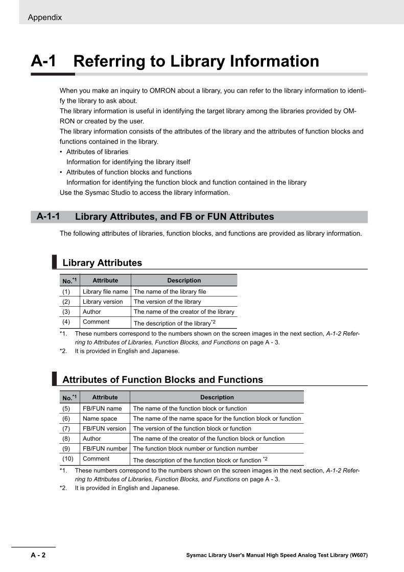
A-1 Referring to Library InformationWhen you make an inquiry to OMRON about a library, you can refer to the library information to identi-fy the library to ask about.The library information is useful in identifying the target library among the libraries provided by OM-RON or created by the user.The library information consists of the attributes of the library and the attributes of function blocks andfunctions contained in the library.• Attributes of libraries
Information for identifying the library itself• Attributes of function blocks and functions
Information for identifying the function block and function contained in the libraryUse the Sysmac Studio to access the library information.
A-1-1 Library Attributes, and FB or FUN AttributesThe following attributes of libraries, function blocks, and functions are provided as library information.
Library Attributes
No.*1 Attribute Description
(1) Library file name The name of the library file(2) Library version The version of the library(3) Author The name of the creator of the library(4) Comment The description of the library*2
*1. These numbers correspond to the numbers shown on the screen images in the next section, A-1-2 Refer-ring to Attributes of Libraries, Function Blocks, and Functions on page A - 3.
*2. It is provided in English and Japanese.
Attributes of Function Blocks and Functions
No.*1 Attribute Description
(5) FB/FUN name The name of the function block or function(6) Name space The name of the name space for the function block or function(7) FB/FUN version The version of the function block or function(8) Author The name of the creator of the function block or function(9) FB/FUN number The function block number or function number(10) Comment The description of the function block or function *2
*1. These numbers correspond to the numbers shown on the screen images in the next section, A-1-2 Refer-ring to Attributes of Libraries, Function Blocks, and Functions on page A - 3.
*2. It is provided in English and Japanese.
Appendix
A - 2 Sysmac Library User's Manual High Speed Analog Test Library (W607)
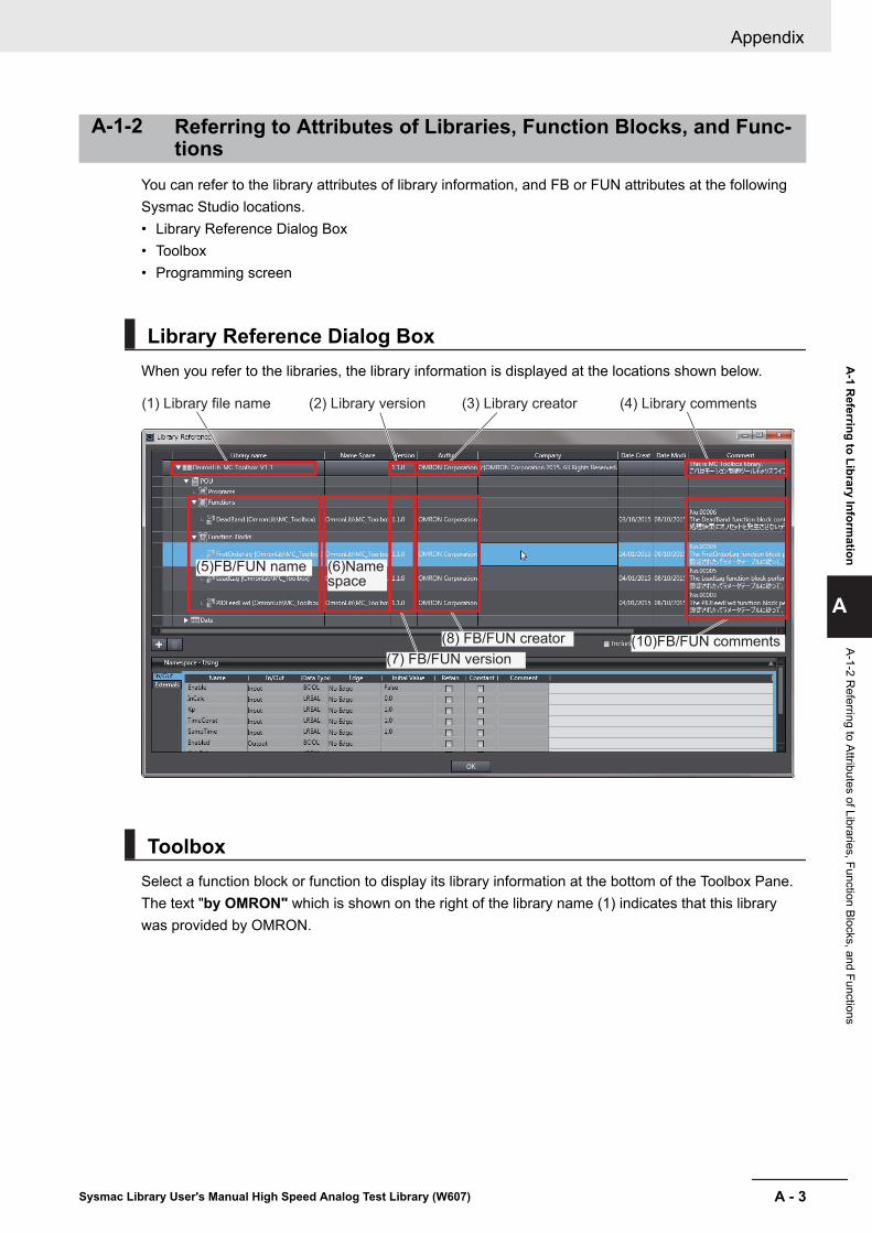
A-1-2 Referring to Attributes of Libraries, Function Blocks, and Func-tions
You can refer to the library attributes of library information, and FB or FUN attributes at the followingSysmac Studio locations.• Library Reference Dialog Box• Toolbox• Programming screen
Library Reference Dialog BoxWhen you refer to the libraries, the library information is displayed at the locations shown below.
(2) Library version(1) Library file name (3) Library creator (4) Library comments
(5)FB/FUN name
(7) FB/FUN version
(8) FB/FUN creator (10)FB/FUN comments
(6)Name space
ToolboxSelect a function block or function to display its library information at the bottom of the Toolbox Pane.The text "by OMRON" which is shown on the right of the library name (1) indicates that this librarywas provided by OMRON.
Appendix
A - 3Sysmac Library User's Manual High Speed Analog Test Library (W607)
A-1 R
eferring to Library Information
A
A-1-2 Referring to Attributes of Libraries, Function Blocks, and Functions

(5)FB/FUN name (6)Name space(1)Library file name(9)FB/FUN number(10)FB/FUN comment(7)FB/FUN version(8)FB/FUN author
Programming ScreenPlace the mouse on a function block and function to display the library information in a tooltip.
(6)Name space(5)FB/FUN name
(10)FB/FUN comment
(9)FB/FUN number
Appendix
A - 4 Sysmac Library User's Manual High Speed Analog Test Library (W607)

A-2 Referring to Function Block andFunction Source Codes
You can refer to the source codes of function blocks and functions provided by OMRON to customizethem to suit the user's environment.User function blocks and user functions can be created based on the copies of these source codes.The following are the examples of items that you may need to customize.• Customizing the "Array Size" to suit the memory capacity of the user's Controller• Customizing the "Data Type" to suit the user-defined data typesNote that you can access only function blocks and functions whose Source code published/not pub-lished is set to "Published " in the library information shown in their individual specifications.Use the following procedure to refer to the source codes of function blocks and functions.
1 Select a function block or function in the program.
2 Double-click or right-click and select To Lower Layer from the menu.The source code is displayed.
Appendix
A - 5Sysmac Library User's Manual High Speed Analog Test Library (W607)
A-2 R
eferring to Function Block and Function Source C
odes
A

Precautions for Correct Use
• For function blocks and functions whose source codes are not published, the following dialogbox is displayed in the above step 2. Click the Cancel button.
Appendix
A - 6 Sysmac Library User's Manual High Speed Analog Test Library (W607)

IIndex
I - 1Sysmac Library User's Manual High Speed Analog Test Library (W607)
I

IndexC
CalcFeatureValues........................................................ 5 - 25CSVToLogData..............................................................5 - 41
D
DataRecorder................................................................ 5 - 12DeviceVariableToArray_***.............................................. 4 - 2
L
LimitAlarm_HAD............................................................ 4 - 14LimitTest........................................................................ 5 - 19LogDataToCSV..............................................................5 - 34
S
ScaleTrans_HAD........................................................... 4 - 11
T
TrigControl.......................................................................5 - 2
Index
I - 2 Sysmac Library User's Manual High Speed Analog Test Library (W607)


Authorized Distributor:
In the interest of product improvement, specifications are subject to change without notice.
Cat. No. W607-E1-01 0518
© OMRON Corporation 2018 All Rights Reserved.
OMRON Corporation Industrial Automation Company
OMRON ELECTRONICS LLC2895 Greenspoint Parkway, Suite 200 Hoffman Estates, IL 60169 U.S.A.Tel: (1) 847-843-7900/Fax: (1) 847-843-7787
Regional Headquarters
OMRON EUROPE B.V.Wegalaan 67-69, 2132 JD HoofddorpThe NetherlandsTel: (31)2356-81-300/Fax: (31)2356-81-388
Contact: www.ia.omron.com
Kyoto, JAPAN
OMRON ASIA PACIFIC PTE. LTD.No. 438A Alexandra Road # 05-05/08 (Lobby 2), Alexandra Technopark, Singapore 119967Tel: (65) 6835-3011/Fax: (65) 6835-2711
OMRON (CHINA) CO., LTD.Room 2211, Bank of China Tower, 200 Yin Cheng Zhong Road, PuDong New Area, Shanghai, 200120, ChinaTel: (86) 21-5037-2222/Fax: (86) 21-5037-2200