sysdrive jx series - minhhungauto.files.wordpress.com · 3.11.2011 · adjustment, jogging...
TRANSCRIPT

CSM_3G3JX_DS_E_1_1
1
Simple, Compact Inverters
SYSDRIVE JX SeriesEasy-to-Use Compact Simplified Inverter for the Customer's Environment and Application Demands
• Provides a wide ranging capacity from 0.2 to 3.7 kW in spite of the compact size
• The main circuit adopts upper/lower wiring as with a conductor• Side-by-side mounting Contributes to space saving• The PID function is featured for the easier control of the fan and pump• The three-phase models incorporate a zero-phase reactor (radio noise filter)
as a standard specification• ModBus-RTU communication allows you to perform network operation at low
cost.
2
SYSDRIVE JX Series
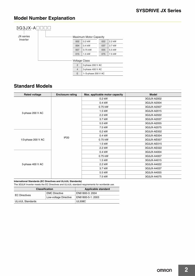
Model Number Explanation
Standard Models
International Standards (EC Directives and UL/cUL Standards)The 3G3JX Inverter meets the EC Directives and UL/cUL standard requirements for worldwide use.
Rated voltage Enclosure rating Max. applicable motor capacity Model
3-phase 200 V AC
IP20
0.2 kW 3G3JX-A2002
0.4 kW 3G3JX-A2004
0.75 kW 3G3JX-A2007
1.5 kW 3G3JX-A2015
2.2 kW 3G3JX-A2022
3.7 kW 3G3JX-A2037
5.5 kW 3G3JX-A2055
7.5 kW 3G3JX-A2075
1/3-phase 200 V AC
0.2 kW 3G3JX-AE002
0.4 kW 3G3JX-AE004
0.75 kW 3G3JX-AE007
1.5 kW 3G3JX-AE015
2.2 kW 3G3JX-AE022
3-phase 400 V AC
0.4 kW 3G3JX-A4004
0.75 kW 3G3JX-A4007
1.5 kW 3G3JX-A4015
2.2 kW 3G3JX-A4022
3.7 kW 3G3JX-A4037
5.5 kW 3G3JX-A4055
7.5 kW 3G3JX-A4075
Classification Applicable standard
EC DirectivesEMC Directive EN61800-3: 2004
Low-voltage Directive EN61800-5-1: 2003
UL/cUL Standards UL508C
3G3JX-A@@@@
Maximum Motor Capacity
Voltage Class
JX-seriesInverter
002
004
007
0.2 kW
0.4 kW
0.75 kW
022
037
2.2 kW
3.7 kW
015 1.5 kW 075 7.5 kW
055 5.5 kW
2
4
3-phase 200 V AC
3-phase 400 V AC
E 1-/3-phase 200 V AC
SYSDRIVE JX Series
3
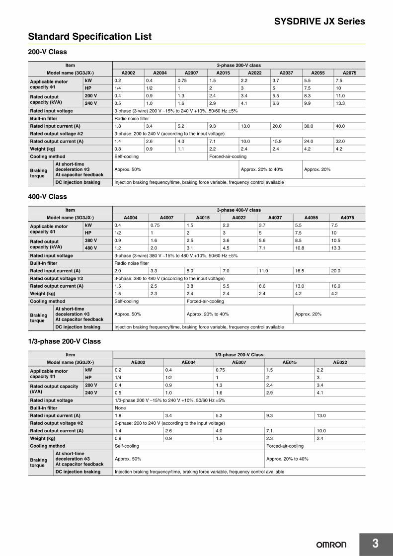
Standard Specification List
200-V Class
400-V Class
1/3-phase 200-V Class
Item 3-phase 200-V class
Model name (3G3JX-) A2002 A2004 A2007 A2015 A2022 A2037 A2055 A2075
Applicable motor capacity *1
kW 0.2 0.4 0.75 1.5 2.2 3.7 5.5 7.5
HP 1/4 1/2 1 2 3 5 7.5 10
Rated output capacity (kVA)
200 V 0.4 0.9 1.3 2.4 3.4 5.5 8.3 11.0
240 V 0.5 1.0 1.6 2.9 4.1 6.6 9.9 13.3
Rated input voltage 3-phase (3-wire) 200 V −15% to 240 V +10%, 50/60 Hz ±5%
Built-in filter Radio noise filter
Rated input current (A) 1.8 3.4 5.2 9.3 13.0 20.0 30.0 40.0
Rated output voltage *2 3-phase: 200 to 240 V (according to the input voltage)
Rated output current (A) 1.4 2.6 4.0 7.1 10.0 15.9 24.0 32.0
Weight (kg) 0.8 0.9 1.1 2.2 2.4 2.4 4.2 4.2
Cooling method Self-cooling Forced-air-cooling
Braking torque
At short-time deceleration *3At capacitor feedback
Approx. 50% Approx. 20% to 40% Approx. 20%
DC injection braking Injection braking frequency/time, braking force variable, frequency control available
Item 3-phase 400-V class
Model name (3G3JX-) A4004 A4007 A4015 A4022 A4037 A4055 A4075
Applicable motor capacity *1
kW 0.4 0.75 1.5 2.2 3.7 5.5 7.5
HP 1/2 1 2 3 5 7.5 10
Rated output capacity (kVA)
380 V 0.9 1.6 2.5 3.6 5.6 8.5 10.5
480 V 1.2 2.0 3.1 4.5 7.1 10.8 13.3
Rated input voltage 3-phase (3-wire) 380 V −15% to 480 V +10%, 50/60 Hz ±5%
Built-in filter Radio noise filter
Rated input current (A) 2.0 3.3 5.0 7.0 11.0 16.5 20.0
Rated output voltage *2 3-phase: 380 to 480 V (according to the input voltage)
Rated output current (A) 1.5 2.5 3.8 5.5 8.6 13.0 16.0
Weight (kg) 1.5 2.3 2.4 2.4 2.4 4.2 4.2
Cooling method Self-cooling Forced-air-cooling
Braking torque
At short-time deceleration *3At capacitor feedback
Approx. 50% Approx. 20% to 40% Approx. 20%
DC injection braking Injection braking frequency/time, braking force variable, frequency control available
Item 1/3-phase 200-V Class
Model name (3G3JX-) AE002 AE004 AE007 AE015 AE022
Applicable motor capacity *1
kW 0.2 0.4 0.75 1.5 2.2
HP 1/4 1/2 1 2 3
Rated output capacity (kVA)
200 V 0.4 0.9 1.3 2.4 3.4
240 V 0.5 1.0 1.6 2.9 4.1
Rated input voltage 1/3-phase 200 V −15% to 240 V +10%, 50/60 Hz ±5%
Built-in filter None
Rated input current (A) 1.8 3.4 5.2 9.3 13.0
Rated output voltage *2 3-phase: 200 to 240 V (according to the input voltage)
Rated output current (A) 1.4 2.6 4.0 7.1 10.0
Weight (kg) 0.8 0.9 1.5 2.3 2.4
Cooling method Self-cooling Forced-air-cooling
Braking torque
At short-time deceleration *3At capacitor feedback
Approx. 50% Approx. 20% to 40%
DC injection braking Injection braking frequency/time, braking force variable, frequency control available
SYSDRIVE JX Series
4
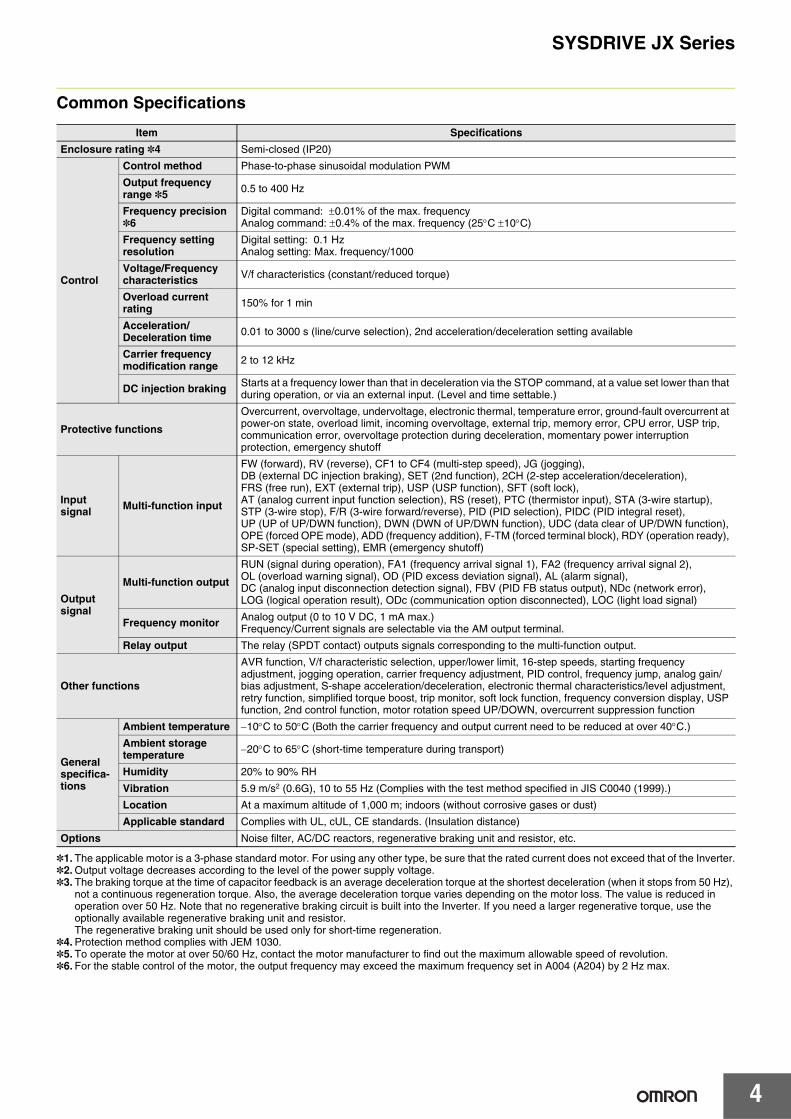
Common Specifications
*1. The applicable motor is a 3-phase standard motor. For using any other type, be sure that the rated current does not exceed that of the Inverter.*2. Output voltage decreases according to the level of the power supply voltage.*3. The braking torque at the time of capacitor feedback is an average deceleration torque at the shortest deceleration (when it stops from 50 Hz),
not a continuous regeneration torque. Also, the average deceleration torque varies depending on the motor loss. The value is reduced in operation over 50 Hz. Note that no regenerative braking circuit is built into the Inverter. If you need a larger regenerative torque, use the optionally available regenerative braking unit and resistor.The regenerative braking unit should be used only for short-time regeneration.
*4. Protection method complies with JEM 1030. *5. To operate the motor at over 50/60 Hz, contact the motor manufacturer to find out the maximum allowable speed of revolution.*6. For the stable control of the motor, the output frequency may exceed the maximum frequency set in A004 (A204) by 2 Hz max.
Item Specifications
Enclosure rating *4 Semi-closed (IP20)
Control
Control method Phase-to-phase sinusoidal modulation PWM
Output frequency range *5 0.5 to 400 Hz
Frequency precision *6
Digital command: ±0.01% of the max. frequencyAnalog command: ±0.4% of the max. frequency (25°C ±10°C)
Frequency setting resolution
Digital setting: 0.1 HzAnalog setting: Max. frequency/1000
Voltage/Frequency characteristics V/f characteristics (constant/reduced torque)
Overload current rating 150% for 1 min
Acceleration/Deceleration time 0.01 to 3000 s (line/curve selection), 2nd acceleration/deceleration setting available
Carrier frequency modification range 2 to 12 kHz
DC injection braking Starts at a frequency lower than that in deceleration via the STOP command, at a value set lower than that during operation, or via an external input. (Level and time settable.)
Protective functions
Overcurrent, overvoltage, undervoltage, electronic thermal, temperature error, ground-fault overcurrent at power-on state, overload limit, incoming overvoltage, external trip, memory error, CPU error, USP trip, communication error, overvoltage protection during deceleration, momentary power interruption protection, emergency shutoff
Input signal Multi-function input
FW (forward), RV (reverse), CF1 to CF4 (multi-step speed), JG (jogging), DB (external DC injection braking), SET (2nd function), 2CH (2-step acceleration/deceleration), FRS (free run), EXT (external trip), USP (USP function), SFT (soft lock), AT (analog current input function selection), RS (reset), PTC (thermistor input), STA (3-wire startup), STP (3-wire stop), F/R (3-wire forward/reverse), PID (PID selection), PIDC (PID integral reset), UP (UP of UP/DWN function), DWN (DWN of UP/DWN function), UDC (data clear of UP/DWN function), OPE (forced OPE mode), ADD (frequency addition), F-TM (forced terminal block), RDY (operation ready), SP-SET (special setting), EMR (emergency shutoff)
Output signal
Multi-function output
RUN (signal during operation), FA1 (frequency arrival signal 1), FA2 (frequency arrival signal 2), OL (overload warning signal), OD (PID excess deviation signal), AL (alarm signal), DC (analog input disconnection detection signal), FBV (PID FB status output), NDc (network error), LOG (logical operation result), ODc (communication option disconnected), LOC (light load signal)
Frequency monitor Analog output (0 to 10 V DC, 1 mA max.)Frequency/Current signals are selectable via the AM output terminal.
Relay output The relay (SPDT contact) outputs signals corresponding to the multi-function output.
Other functions
AVR function, V/f characteristic selection, upper/lower limit, 16-step speeds, starting frequency adjustment, jogging operation, carrier frequency adjustment, PID control, frequency jump, analog gain/bias adjustment, S-shape acceleration/deceleration, electronic thermal characteristics/level adjustment, retry function, simplified torque boost, trip monitor, soft lock function, frequency conversion display, USP function, 2nd control function, motor rotation speed UP/DOWN, overcurrent suppression function
General specifica-tions
Ambient temperature −10°C to 50°C (Both the carrier frequency and output current need to be reduced at over 40°C.)
Ambient storage temperature −20°C to 65°C (short-time temperature during transport)
Humidity 20% to 90% RH
Vibration 5.9 m/s2 (0.6G), 10 to 55 Hz (Complies with the test method specified in JIS C0040 (1999).)
Location At a maximum altitude of 1,000 m; indoors (without corrosive gases or dust)
Applicable standard Complies with UL, cUL, CE standards. (Insulation distance)
Options Noise filter, AC/DC reactors, regenerative braking unit and resistor, etc.
SYSDRIVE JX Series
5
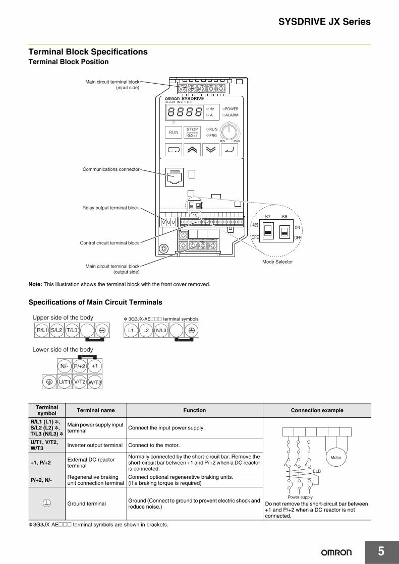
Terminal Block SpecificationsTerminal Block Position
Note: This illustration shows the terminal block with the front cover removed.
Specifications of Main Circuit Terminals
* 3G3JX-AE@@@ terminal symbols are shown in brackets.
Terminal symbol Terminal name Function Connection example
R/L1 (L1) *, S/L2 (L2) *, T/L3 (N/L3) *
Main power supply input terminal Connect the input power supply.
Do not remove the short-circuit bar between +1 and P/+2 when a DC reactor is not connected.
U/T1, V/T2, W/T3 Inverter output terminal Connect to the motor.
+1, P/+2 External DC reactor terminal
Normally connected by the short-circuit bar. Remove the short-circuit bar between +1 and P/+2 when a DC reactor is connected.
P/+2, N/- Regenerative braking unit connection terminal
Connect optional regenerative braking units.(If a braking torque is required)
Ground terminal Ground (Connect to ground to prevent electric shock and reduce noise.)
8k8k8k8
S7 S8
485
OPE
ON
OFF
Main circuit terminal block (input side)
Communications connector
Relay output terminal block
Control circuit terminal block
Main circuit terminal block (output side)
Mode Selector
T/L3 L1 L2 N/L3R/L1 S/L2
N/- P/+2 +1
U/T1 V/T2 W/T3
Upper side of the body
Lower side of the body
* 3G3JX-AE@@@ terminal symbols
Power supply
ELB
Motor
SYSDRIVE JX Series
6
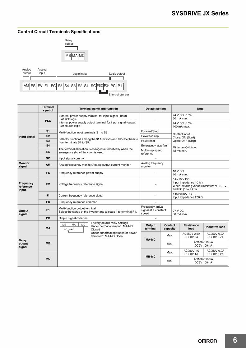
Control Circuit Terminals Specifications
Terminal symbol Terminal name and function Default setting Note
Input signal
PSC
External power supply terminal for input signal (input)...At sink logicInternal power supply output terminal for input signal (output)...At source logic
−
24 V DC ±10%30 mA max.
24 V DC ±10%100 mA max.
S1 Multi-function input terminals S1 to S5
Select 5 functions among the 31 functions and allocate them to from terminals S1 to S5.
The terminal allocation is changed automatically when the emergency shutoff function is used.
Forward/StopContact inputClose: ON (Start)Open: OFF (Stop)
Minimum ON time:12 ms min.
S2 Reverse/Stop
S3 Fault reset
S4 Emergency stop fault
S5 Multi-step speed reference 1
SC Input signal common −
Monitor signal AM Analog frequency monitor/Analog output current monitor Analog frequency
monitor
Frequency reference input
FS Frequency reference power supply − 10 V DC10 mA max.
FV Voltage frequency reference signal −
0 to 10 V DCInput impedance 10 kΩWhen installing variable resistors at FS, FV, and FC (1 to 2 kΩ)
FI Current frequency reference signal − 4 to 20 mA DCInput impedance 250 Ω
FC Frequency reference common −
Output signal
P1 Multi-function output terminalSelect the status of the Inverter and allocate it to terminal P1.
Frequency arrival signal at a constant speed
27 V DC50 mA max.
PC Output signal common −
Relay output signal
MA
Factory default relay settingsUnder normal operation: MA-MC ClosedUnder abnormal operation or power shutdown: MA-MC Open
MB
MC
MB MA MC
AM FS FV FI FC S5 S4 S3 S2 S1 SC PSC P24 PC P1
Relayoutput
Analogoutput Logic input Logic output
Short-circuit bar
Analoginput
MB MA MC Output terminal
Contact capacity
Resistance load Inductive load
MA-MCMax. AC250V 2.5A
DC30V 3AAC250V 0.2ADC30V 0.7A
Min. AC100V 10mADC5V 100mA
MB-MCMax. AC250V 1A
DC30V 1AAC250V 0.2ADC30V 0.2A
Min. AC100V 10mADC5V 100mA
SYSDRIVE JX Series
7
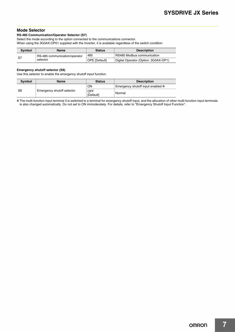
Mode SelectorRS-485 Communication/Operator Selector (S7)Select the mode according to the option connected to the communications connector.When using the 3G3AX-OP01 supplied with the Inverter, it is available regardless of the switch condition
Emergency shutoff selector (S8)Use this selector to enable the emergency shutoff input function.
* The multi-function input terminal 3 is switched to a terminal for emergency shutoff input, and the allocation of other multi-function input terminals is also changed automatically. Do not set to ON immoderately. For details, refer to "Emergency Shutoff Input Function".
Symbol Name Status Description
S7 RS-485 communication/operator selector
485 RS485 Modbus communication
OPE [Default] Digital Operator (Option: 3G3AX-OP1)
Symbol Name Status Description
S8 Emergency shutoff selectorON Emergency shutoff input enabled *OFF[Default] Normal
8
SYSDRIVE JX Series
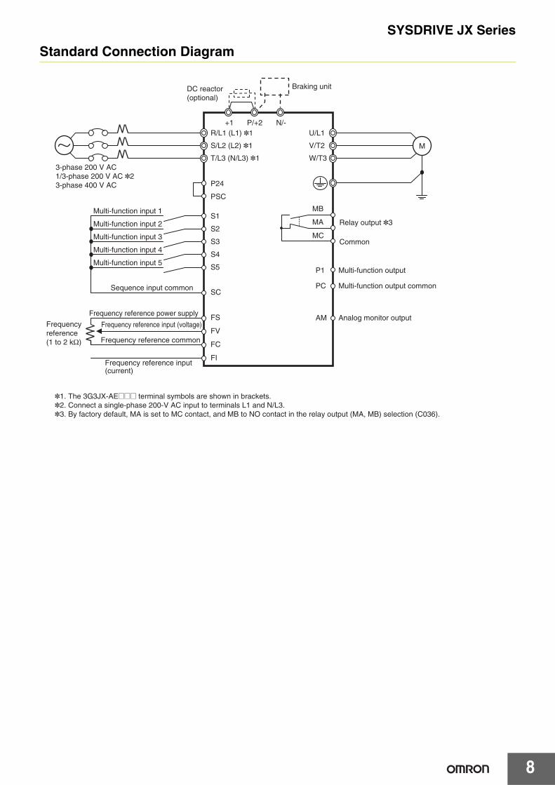
Standard Connection Diagram
Braking unitDC reactor (optional)
3-phase 200 V AC1/3-phase 200 V AC *23-phase 400 V AC
Multi-function input 1
Multi-function input 2
Multi-function input 3
Multi-function input 4
Multi-function input 5
Frequency reference power supply
Frequency reference (1 to 2 kΩ)
Frequency reference input (voltage)
Frequency reference input (current)
*1. The 3G3JX-AE@@@ terminal symbols are shown in brackets.*2. Connect a single-phase 200-V AC input to terminals L1 and N/L3.*3. By factory default, MA is set to MC contact, and MB to NO contact in the relay output (MA, MB) selection (C036).
Frequency reference common
Sequence input common
M
R/L1 (L1) *1+1 P/+2 N/-
T/L3 (N/L3) *1
S/L2 (L2) *1
U/L1
W/T3
P1
PC
Multi-function output
Multi-function output common
AM Analog monitor output
Relay output *3
Common
V/T2
PSC
P24
S2
S1
S5
SC
FS
FI
FC
FV
S4
S3
MB
MA
MC
SYSDRIVE JX Series
9
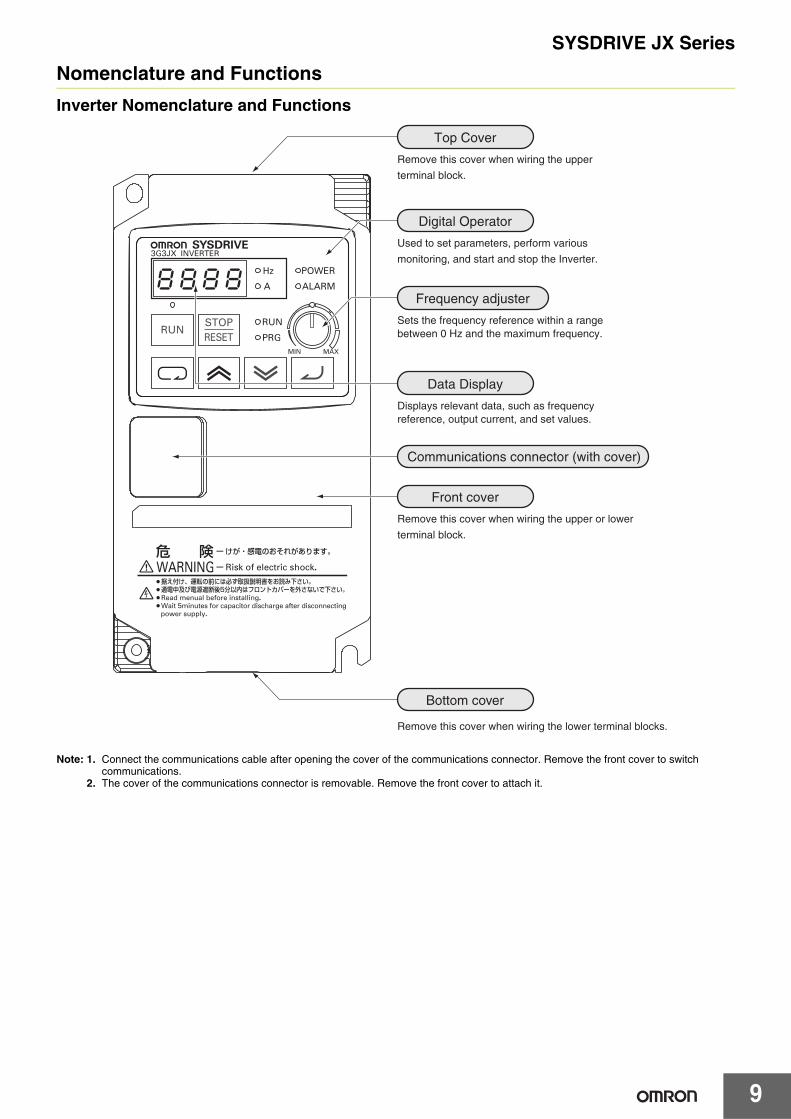
Nomenclature and Functions
Inverter Nomenclature and Functions
Note: 1. Connect the communications cable after opening the cover of the communications connector. Remove the front cover to switch communications.
2. The cover of the communications connector is removable. Remove the front cover to attach it.
8k8k8k8
Bottom cover
Remove this cover when wiring the lower terminal blocks.
Remove this cover when wiring the upper
terminal block.
Used to set parameters, perform various
monitoring, and start and stop the Inverter.
Displays relevant data, such as frequency reference, output current, and set values.
Top Cover
Digital Operator
Data Display
Remove this cover when wiring the upper or lower
terminal block.
Front cover
Sets the frequency reference within a range between 0 Hz and the maximum frequency.
Frequency adjuster
Communications connector (with cover)
SYSDRIVE JX Series
10
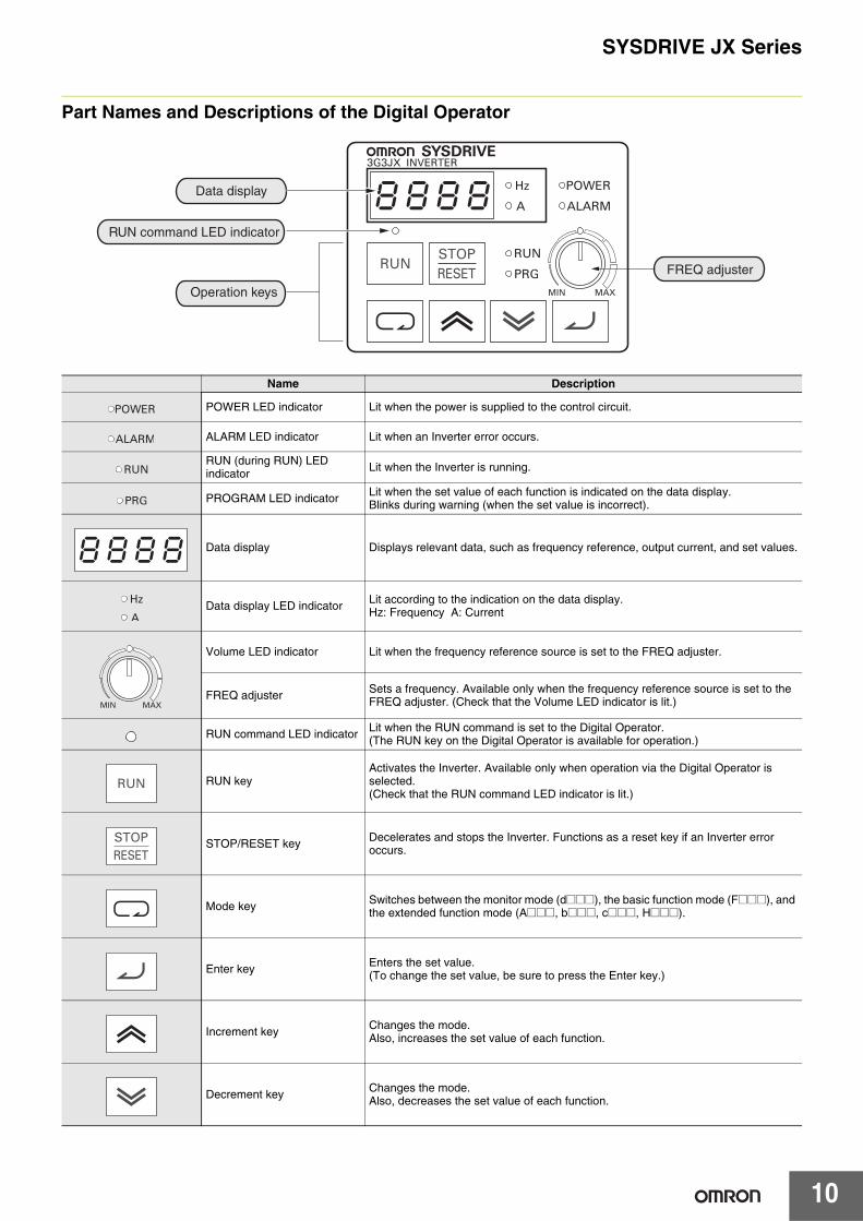
Part Names and Descriptions of the Digital Operator
Name Description
POWER LED indicator Lit when the power is supplied to the control circuit.
ALARM LED indicator Lit when an Inverter error occurs.
RUN (during RUN) LED indicator Lit when the Inverter is running.
PROGRAM LED indicator Lit when the set value of each function is indicated on the data display.Blinks during warning (when the set value is incorrect).
Data display Displays relevant data, such as frequency reference, output current, and set values.
Data display LED indicator Lit according to the indication on the data display.Hz: Frequency A: Current
Volume LED indicator Lit when the frequency reference source is set to the FREQ adjuster.
FREQ adjuster Sets a frequency. Available only when the frequency reference source is set to the FREQ adjuster. (Check that the Volume LED indicator is lit.)
RUN command LED indicator Lit when the RUN command is set to the Digital Operator.(The RUN key on the Digital Operator is available for operation.)
RUN keyActivates the Inverter. Available only when operation via the Digital Operator is selected.(Check that the RUN command LED indicator is lit.)
STOP/RESET key Decelerates and stops the Inverter. Functions as a reset key if an Inverter error occurs.
Mode key Switches between the monitor mode (d@@@), the basic function mode (F@@@), and the extended function mode (A@@@, b@@@, c@@@, H@@@).
Enter key Enters the set value.(To change the set value, be sure to press the Enter key.)
Increment key Changes the mode.Also, increases the set value of each function.
Decrement key Changes the mode.Also, decreases the set value of each function.
8k8k8k8Data display
RUN command LED indicator
Operation keys
FREQ adjuster
8k8k8k8
SYSDRIVE JX Series
11
Dimensions (Unit: mm)
143±0.2
5
155
67±0.2
80
5
6
2.6
D1
D1.9
3G3JX-A20023G3JX-A20043G3JX-A20073G3JX-AE0023G3JX-AE004
Rated voltage
Model3G3JX-
Dimensions (mm)D D1
3phase200 V AC
A2002 95.5 13A2004 109.5 27A2007 132.5 50
1/3phase200 V AC
AE002 95.5 13AE004 109.5 27
6
5
5
110
176±0.3
98±0.3
189
28
2.6
1.9 130.5
3G3JX-A40043G3JX-AE007
SYSDRIVE JX Series
12
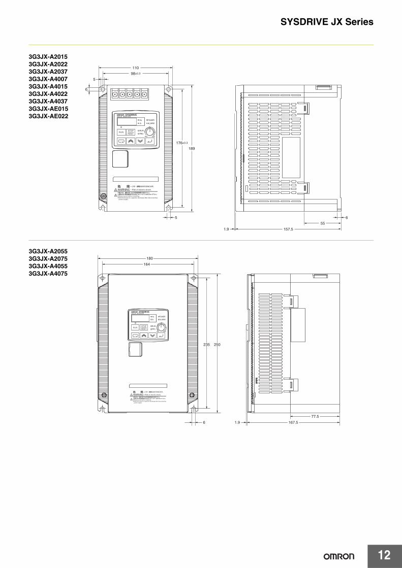
6
5
5
110
176±0.3
98±0.3
189
6
55
1.9 157.5
3G3JX-A20153G3JX-A20223G3JX-A20373G3JX-A40073G3JX-A40153G3JX-A40223G3JX-A40373G3JX-AE0153G3JX-AE022
180
164
250
167.5
77.5
235
6 1.9
3G3JX-A20553G3JX-A20753G3JX-A40553G3JX-A4075
SYSDRIVE JX Series
13
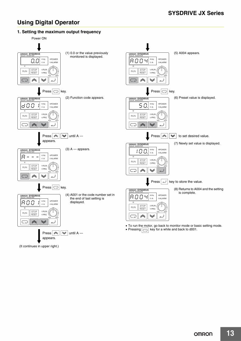
Using Digital Operator
1. Setting the maximum output frequencyPower ON
(1) 0.0 or the value previously monitored is displayed.
(2) Function code appears.
(3) A --- appears.
(4) A001 or the code number set in the end of last setting is displayed.
(It continues in upper right.)
0.0
Press key.
Ddk0k0k1
Press until A --- appears.
ak-k-k-
Press key.
ak0k0k1
Press until A --- appears.
(5) A004 appears.
(6) Preset value is displayed.
(7) Newly set value is displayed.
(8) Returns to A004 and the setting is complete.
• To run the motor, go back to monitor mode or basic setting mode.• Pressing key for a while and back to d001.
ak0k0k4
Press key.
5k0.
Press to set desired value.
1k0k0.
Press key to store the value.
ak0k0k4
SYSDRIVE JX Series
14
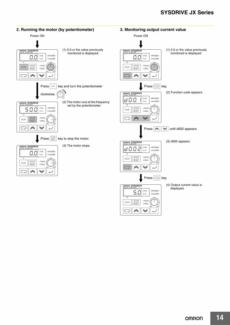
2. Running the motor (by potentiometer) 3. Monitoring output current valuePower ON
(1) 0.0 or the value previously monitored is displayed.
(2) The motor runs at the frequency set by the potentiometer.
(3) The motor stops.
0.0
Press key and turn the potentiometer
clockwise.
D5k0k0
Press key to stop the motor.
0.0
Power ON
(1) 0.0 or the value previously monitored is displayed.
(2) Function code appears.
(3) d002 appears.
(4) Output current value is displayed.
0.0
Press key.
Ddk0k0k1
Press until d002 appears.
Ddk0k0k2
Press key.
5.0
SYSDRIVE JX Series
15
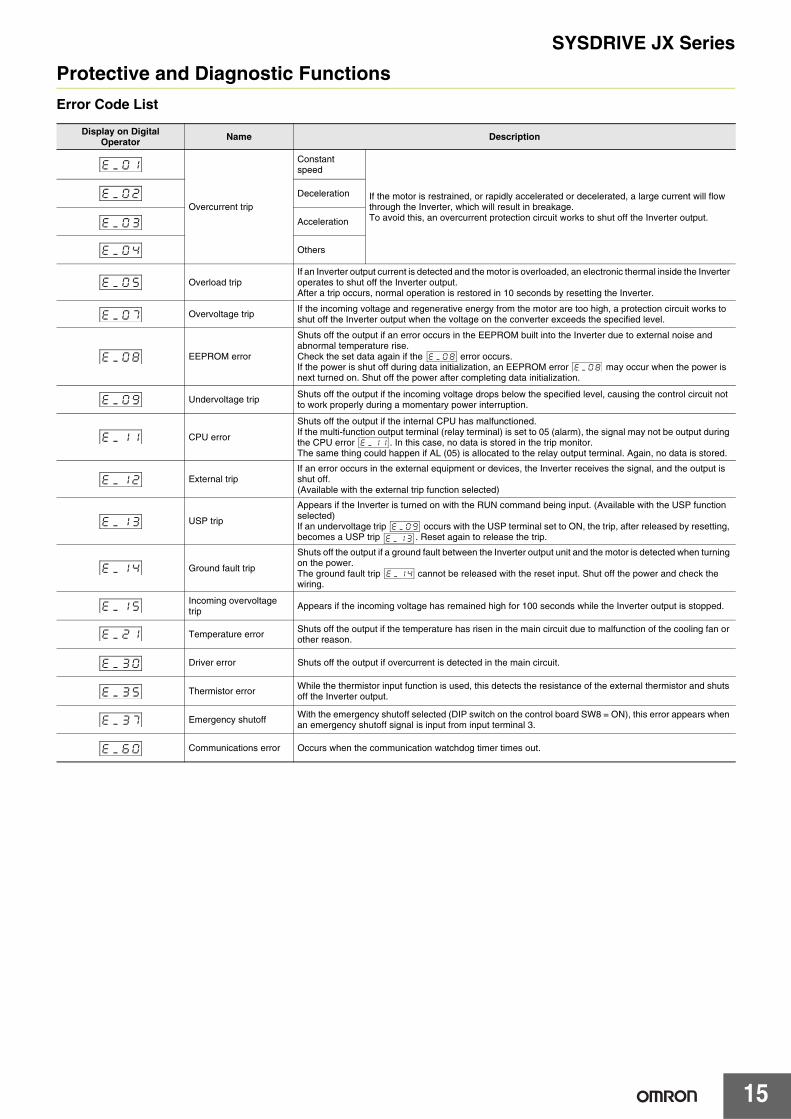
Protective and Diagnostic Functions
Error Code List
Display on Digital Operator Name Description
Overcurrent trip
Constant speed
If the motor is restrained, or rapidly accelerated or decelerated, a large current will flow through the Inverter, which will result in breakage.To avoid this, an overcurrent protection circuit works to shut off the Inverter output.
Deceleration
Acceleration
Others
Overload tripIf an Inverter output current is detected and the motor is overloaded, an electronic thermal inside the Inverter operates to shut off the Inverter output.After a trip occurs, normal operation is restored in 10 seconds by resetting the Inverter.
Overvoltage trip If the incoming voltage and regenerative energy from the motor are too high, a protection circuit works to shut off the Inverter output when the voltage on the converter exceeds the specified level.
EEPROM error
Shuts off the output if an error occurs in the EEPROM built into the Inverter due to external noise and abnormal temperature rise.Check the set data again if the error occurs.If the power is shut off during data initialization, an EEPROM error may occur when the power is next turned on. Shut off the power after completing data initialization.
Undervoltage trip Shuts off the output if the incoming voltage drops below the specified level, causing the control circuit not to work properly during a momentary power interruption.
CPU error
Shuts off the output if the internal CPU has malfunctioned.If the multi-function output terminal (relay terminal) is set to 05 (alarm), the signal may not be output during the CPU error . In this case, no data is stored in the trip monitor.The same thing could happen if AL (05) is allocated to the relay output terminal. Again, no data is stored.
External tripIf an error occurs in the external equipment or devices, the Inverter receives the signal, and the output is shut off.(Available with the external trip function selected)
USP trip
Appears if the Inverter is turned on with the RUN command being input. (Available with the USP function selected)If an undervoltage trip occurs with the USP terminal set to ON, the trip, after released by resetting, becomes a USP trip . Reset again to release the trip.
Ground fault trip
Shuts off the output if a ground fault between the Inverter output unit and the motor is detected when turning on the power.The ground fault trip cannot be released with the reset input. Shut off the power and check the wiring.
Incoming overvoltage trip Appears if the incoming voltage has remained high for 100 seconds while the Inverter output is stopped.
Temperature error Shuts off the output if the temperature has risen in the main circuit due to malfunction of the cooling fan or other reason.
Driver error Shuts off the output if overcurrent is detected in the main circuit.
Thermistor error While the thermistor input function is used, this detects the resistance of the external thermistor and shuts off the Inverter output.
Emergency shutoff With the emergency shutoff selected (DIP switch on the control board SW8 = ON), this error appears when an emergency shutoff signal is input from input terminal 3.
Communications error Occurs when the communication watchdog timer times out.
ek_k0k1
ek_k0k2
ek_k0k3
ek_k0k4
ek_k0k5
ek_k0k7
ek_k0k8 ek_k0k8 ek_k0k8
ek_k0k9
ek_k1k1 ek_k1k1
ek_k1k2
ek_k1k3 ek_k0k9 ek_k1k3
ek_k1k4 ek_k1k4
ek_k1k5
ek_k2k1
ek_k3k0
ek_k3k5
ek_k3k7
ek_k6k0
16
SYSDRIVE JX Series
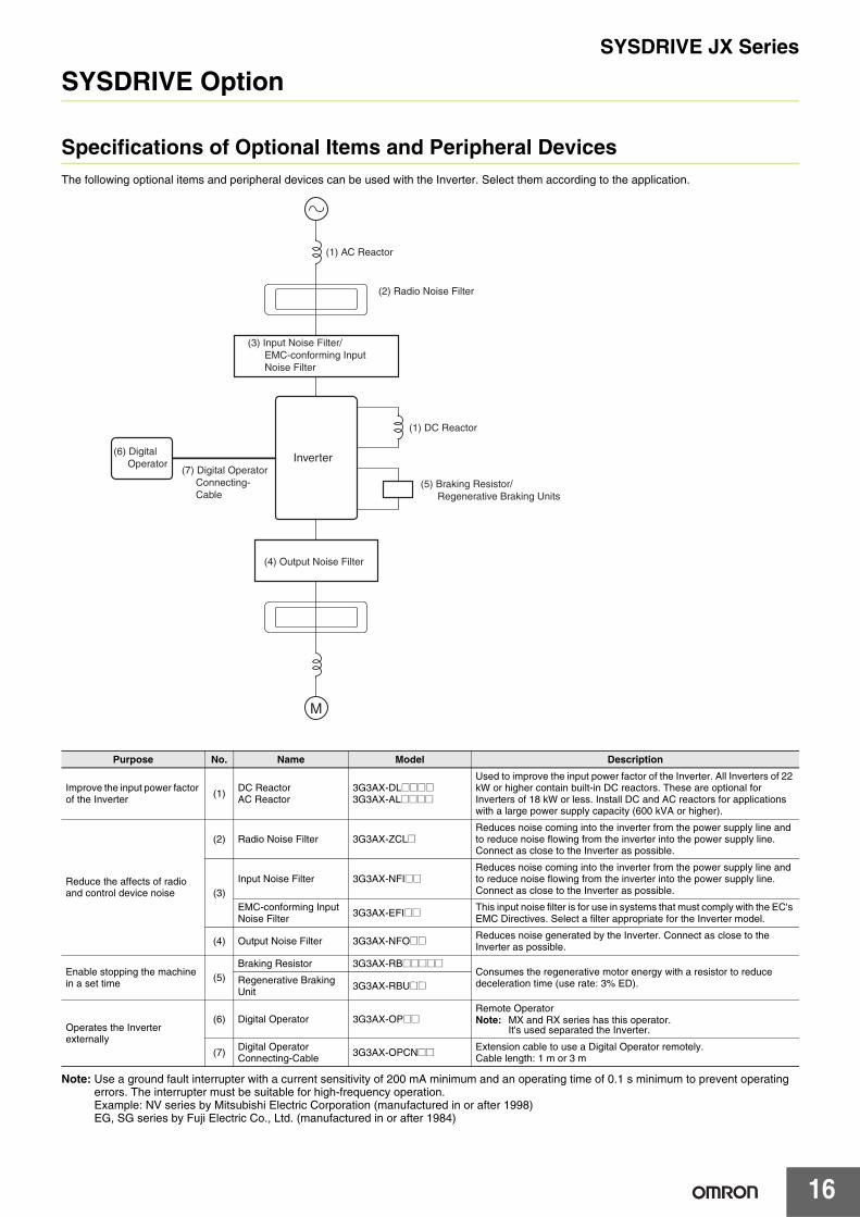
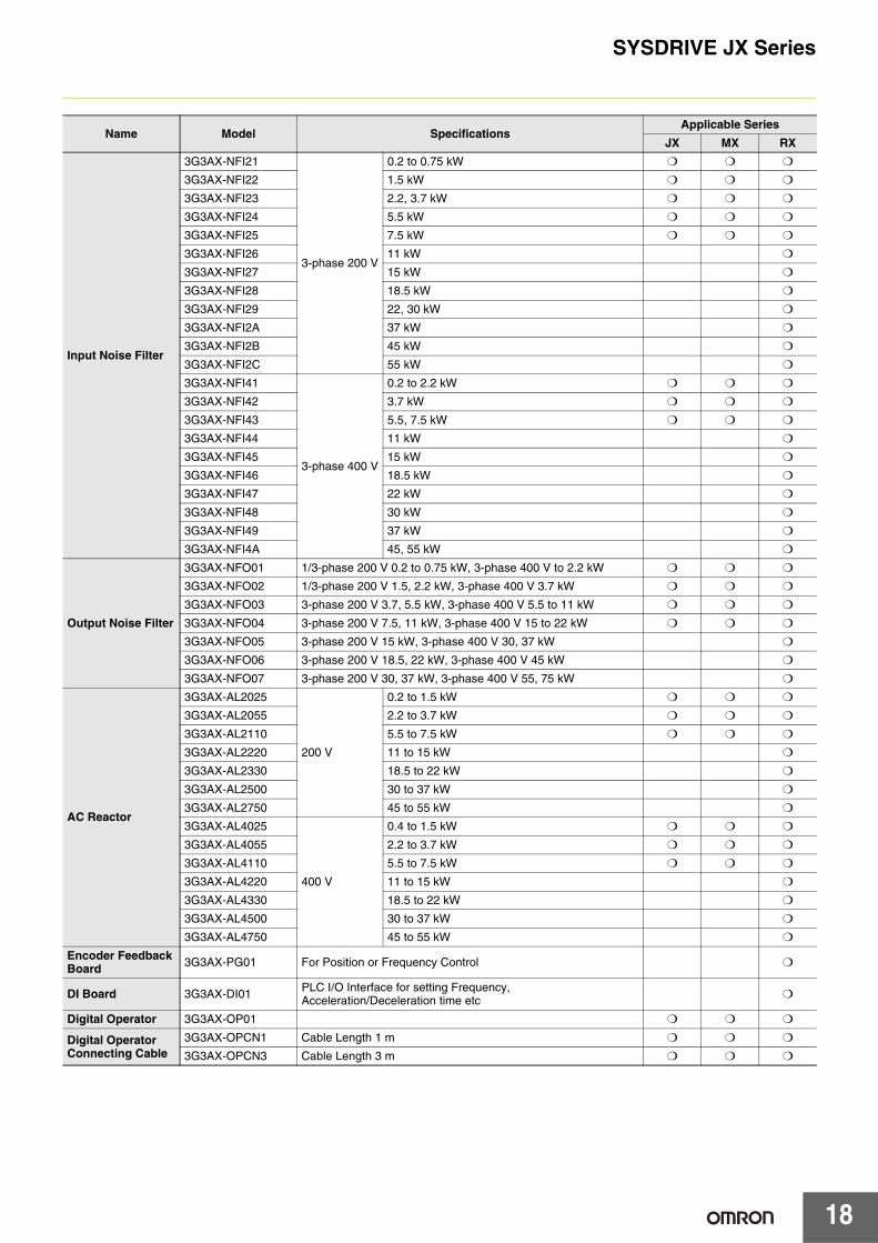
SYSDRIVE Option
Specifications of Optional Items and Peripheral DevicesThe following optional items and peripheral devices can be used with the Inverter. Select them according to the application.
Note: Use a ground fault interrupter with a current sensitivity of 200 mA minimum and an operating time of 0.1 s minimum to prevent operating errors. The interrupter must be suitable for high-frequency operation.Example: NV series by Mitsubishi Electric Corporation (manufactured in or after 1998)EG, SG series by Fuji Electric Co., Ltd. (manufactured in or after 1984)
Purpose No. Name Model Description
Improve the input power factor of the Inverter (1) DC Reactor
AC Reactor3G3AX-DL@@@@3G3AX-AL@@@@
Used to improve the input power factor of the Inverter. All Inverters of 22 kW or higher contain built-in DC reactors. These are optional for Inverters of 18 kW or less. Install DC and AC reactors for applications with a large power supply capacity (600 kVA or higher).
Reduce the affects of radio and control device noise
(2) Radio Noise Filter 3G3AX-ZCL@Reduces noise coming into the inverter from the power supply line and to reduce noise flowing from the inverter into the power supply line. Connect as close to the Inverter as possible.
(3)Input Noise Filter 3G3AX-NFI@@
Reduces noise coming into the inverter from the power supply line and to reduce noise flowing from the inverter into the power supply line. Connect as close to the Inverter as possible.
EMC-conforming Input Noise Filter 3G3AX-EFI@@ This input noise filter is for use in systems that must comply with the EC's
EMC Directives. Select a filter appropriate for the Inverter model.
(4) Output Noise Filter 3G3AX-NFO@@ Reduces noise generated by the Inverter. Connect as close to the Inverter as possible.
Enable stopping the machine in a set time (5)
Braking Resistor 3G3AX-RB@@@@@Consumes the regenerative motor energy with a resistor to reduce deceleration time (use rate: 3% ED).Regenerative Braking
Unit 3G3AX-RBU@@
Operates the Inverter externally
(6) Digital Operator 3G3AX-OP@@Remote OperatorNote: MX and RX series has this operator.
It's used separated the Inverter.
(7) Digital Operator Connecting-Cable 3G3AX-OPCN@@ Extension cable to use a Digital Operator remotely.
Cable length: 1 m or 3 m
M
(1) AC Reactor
(2) Radio Noise Filter
(1) DC Reactor
Inverter
(3) Input Noise Filter/ EMC-conforming Input Noise Filter
(4) Output Noise Filter
(5) Braking Resistor/ Regenerative Braking Units
(6) Digital Operator
(7) Digital Operator Connecting- Cable
SYSDRIVE JX Series
17
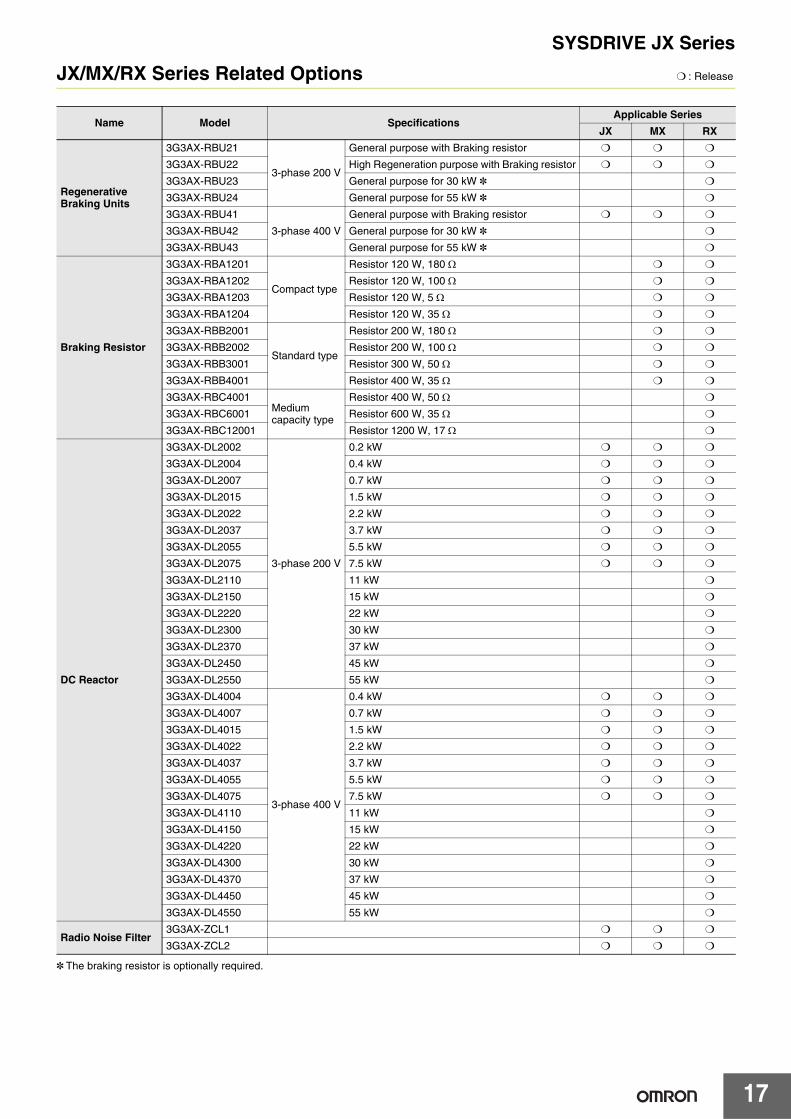
JX/MX/RX Series Related Options ❍ : Release
* The braking resistor is optionally required.
Name Model SpecificationsApplicable Series
JX MX RX
Regenerative Braking Units
3G3AX-RBU21
3-phase 200 V
General purpose with Braking resistor ❍ ❍ ❍
3G3AX-RBU22 High Regeneration purpose with Braking resistor ❍ ❍ ❍
3G3AX-RBU23 General purpose for 30 kW * ❍
3G3AX-RBU24 General purpose for 55 kW * ❍
3G3AX-RBU41
3-phase 400 V
General purpose with Braking resistor ❍ ❍ ❍
3G3AX-RBU42 General purpose for 30 kW * ❍
3G3AX-RBU43 General purpose for 55 kW * ❍
Braking Resistor
3G3AX-RBA1201
Compact type
Resistor 120 W, 180 Ω ❍ ❍
3G3AX-RBA1202 Resistor 120 W, 100 Ω ❍ ❍
3G3AX-RBA1203 Resistor 120 W, 5 Ω ❍ ❍
3G3AX-RBA1204 Resistor 120 W, 35 Ω ❍ ❍
3G3AX-RBB2001
Standard type
Resistor 200 W, 180 Ω ❍ ❍
3G3AX-RBB2002 Resistor 200 W, 100 Ω ❍ ❍
3G3AX-RBB3001 Resistor 300 W, 50 Ω ❍ ❍
3G3AX-RBB4001 Resistor 400 W, 35 Ω ❍ ❍
3G3AX-RBC4001Medium capacity type
Resistor 400 W, 50 Ω ❍
3G3AX-RBC6001 Resistor 600 W, 35 Ω ❍
3G3AX-RBC12001 Resistor 1200 W, 17 Ω ❍
DC Reactor
3G3AX-DL2002
3-phase 200 V
0.2 kW ❍ ❍ ❍
3G3AX-DL2004 0.4 kW ❍ ❍ ❍
3G3AX-DL2007 0.7 kW ❍ ❍ ❍
3G3AX-DL2015 1.5 kW ❍ ❍ ❍
3G3AX-DL2022 2.2 kW ❍ ❍ ❍
3G3AX-DL2037 3.7 kW ❍ ❍ ❍
3G3AX-DL2055 5.5 kW ❍ ❍ ❍
3G3AX-DL2075 7.5 kW ❍ ❍ ❍
3G3AX-DL2110 11 kW ❍
3G3AX-DL2150 15 kW ❍
3G3AX-DL2220 22 kW ❍
3G3AX-DL2300 30 kW ❍
3G3AX-DL2370 37 kW ❍
3G3AX-DL2450 45 kW ❍
3G3AX-DL2550 55 kW ❍
3G3AX-DL4004
3-phase 400 V
0.4 kW ❍ ❍ ❍
3G3AX-DL4007 0.7 kW ❍ ❍ ❍
3G3AX-DL4015 1.5 kW ❍ ❍ ❍
3G3AX-DL4022 2.2 kW ❍ ❍ ❍
3G3AX-DL4037 3.7 kW ❍ ❍ ❍
3G3AX-DL4055 5.5 kW ❍ ❍ ❍
3G3AX-DL4075 7.5 kW ❍ ❍ ❍
3G3AX-DL4110 11 kW ❍
3G3AX-DL4150 15 kW ❍
3G3AX-DL4220 22 kW ❍
3G3AX-DL4300 30 kW ❍
3G3AX-DL4370 37 kW ❍
3G3AX-DL4450 45 kW ❍
3G3AX-DL4550 55 kW ❍
Radio Noise Filter3G3AX-ZCL1 ❍ ❍ ❍
3G3AX-ZCL2 ❍ ❍ ❍
SYSDRIVE JX Series
18
Name Model SpecificationsApplicable Series
JX MX RX
Input Noise Filter
3G3AX-NFI21
3-phase 200 V
0.2 to 0.75 kW ❍ ❍ ❍
3G3AX-NFI22 1.5 kW ❍ ❍ ❍
3G3AX-NFI23 2.2, 3.7 kW ❍ ❍ ❍
3G3AX-NFI24 5.5 kW ❍ ❍ ❍
3G3AX-NFI25 7.5 kW ❍ ❍ ❍
3G3AX-NFI26 11 kW ❍
3G3AX-NFI27 15 kW ❍
3G3AX-NFI28 18.5 kW ❍
3G3AX-NFI29 22, 30 kW ❍
3G3AX-NFI2A 37 kW ❍
3G3AX-NFI2B 45 kW ❍
3G3AX-NFI2C 55 kW ❍
3G3AX-NFI41
3-phase 400 V
0.2 to 2.2 kW ❍ ❍ ❍
3G3AX-NFI42 3.7 kW ❍ ❍ ❍
3G3AX-NFI43 5.5, 7.5 kW ❍ ❍ ❍
3G3AX-NFI44 11 kW ❍
3G3AX-NFI45 15 kW ❍
3G3AX-NFI46 18.5 kW ❍
3G3AX-NFI47 22 kW ❍
3G3AX-NFI48 30 kW ❍
3G3AX-NFI49 37 kW ❍
3G3AX-NFI4A 45, 55 kW ❍
Output Noise Filter
3G3AX-NFO01 1/3-phase 200 V 0.2 to 0.75 kW, 3-phase 400 V to 2.2 kW ❍ ❍ ❍
3G3AX-NFO02 1/3-phase 200 V 1.5, 2.2 kW, 3-phase 400 V 3.7 kW ❍ ❍ ❍
3G3AX-NFO03 3-phase 200 V 3.7, 5.5 kW, 3-phase 400 V 5.5 to 11 kW ❍ ❍ ❍
3G3AX-NFO04 3-phase 200 V 7.5, 11 kW, 3-phase 400 V 15 to 22 kW ❍ ❍ ❍
3G3AX-NFO05 3-phase 200 V 15 kW, 3-phase 400 V 30, 37 kW ❍
3G3AX-NFO06 3-phase 200 V 18.5, 22 kW, 3-phase 400 V 45 kW ❍
3G3AX-NFO07 3-phase 200 V 30, 37 kW, 3-phase 400 V 55, 75 kW ❍
AC Reactor
3G3AX-AL2025
200 V
0.2 to 1.5 kW ❍ ❍ ❍
3G3AX-AL2055 2.2 to 3.7 kW ❍ ❍ ❍
3G3AX-AL2110 5.5 to 7.5 kW ❍ ❍ ❍
3G3AX-AL2220 11 to 15 kW ❍
3G3AX-AL2330 18.5 to 22 kW ❍
3G3AX-AL2500 30 to 37 kW ❍
3G3AX-AL2750 45 to 55 kW ❍
3G3AX-AL4025
400 V
0.4 to 1.5 kW ❍ ❍ ❍
3G3AX-AL4055 2.2 to 3.7 kW ❍ ❍ ❍
3G3AX-AL4110 5.5 to 7.5 kW ❍ ❍ ❍
3G3AX-AL4220 11 to 15 kW ❍
3G3AX-AL4330 18.5 to 22 kW ❍
3G3AX-AL4500 30 to 37 kW ❍
3G3AX-AL4750 45 to 55 kW ❍
Encoder Feedback Board 3G3AX-PG01 For Position or Frequency Control ❍
DI Board 3G3AX-DI01 PLC I/O Interface for setting Frequency, Acceleration/Deceleration time etc ❍
Digital Operator 3G3AX-OP01 ❍ ❍ ❍
Digital Operator Connecting Cable
3G3AX-OPCN1 Cable Length 1 m ❍ ❍ ❍
3G3AX-OPCN3 Cable Length 3 m ❍ ❍ ❍
SYSDRIVE JX Series
19
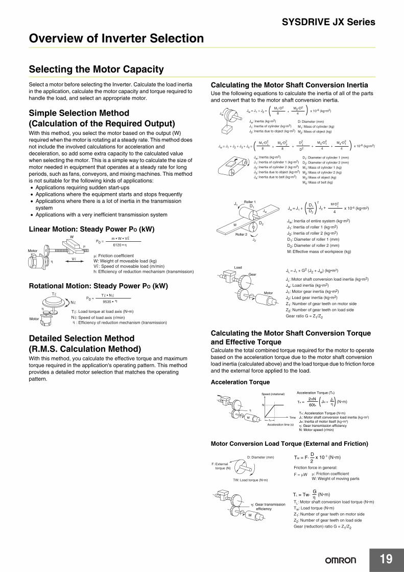
Overview of Inverter Selection
Selecting the Motor CapacitySelect a motor before selecting the Inverter. Calculate the load inertia in the application, calculate the motor capacity and torque required to handle the load, and select an appropriate motor.
Simple Selection Method (Calculation of the Required Output)With this method, you select the motor based on the output (W) required when the motor is rotating at a steady rate. This method does not include the involved calculations for acceleration and deceleration, so add some extra capacity to the calculated value when selecting the motor. This is a simple way to calculate the size of motor needed in equipment that operates at a steady rate for long periods, such as fans, conveyors, and mixing machines. This method is not suitable for the following kinds of applications:• Applications requiring sudden start-ups• Applications where the equipment starts and stops frequently• Applications where there is a lot of inertia in the transmission
system• Applications with a very inefficient transmission system
Linear Motion: Steady Power PO (kW)
Rotational Motion: Steady Power PO (kW)
Detailed Selection Method (R.M.S. Calculation Method)With this method, you calculate the effective torque and maximum torque required in the application's operating pattern. This method provides a detailed motor selection that matches the operating pattern.
Calculating the Motor Shaft Conversion InertiaUse the following equations to calculate the inertia of all of the parts and convert that to the motor shaft conversion inertia.
Calculating the Motor Shaft Conversion Torque and Effective TorqueCalculate the total combined torque required for the motor to operate based on the acceleration torque due to the motor shaft conversion load inertia (calculated above) and the load torque due to friction force and the external force applied to the load.
Acceleration Torque
Motor Conversion Load Torque (External and Friction)
μ: Friction coefficientW: Weight of moveable load (kg)V : Speed of moveable load (m/min)h: Efficiency of reduction mechanism (transmission)
Motor
W
V
μ
m • W • V
6120 • η
η
P0 =
TNη
: Load torque at load axis (N�m)
: Speed of load axis (r/min): Efficiency of reduction mechanism (transmission)
T • N
9535 • ηP0 =
Motor
N
T
η
D1: Diameter of cylinder 1 (mm)
D2: Diameter of cylinder 2 (mm)
M1: Mass of cylinder 1 (kg)
M2: Mass of cylinder 2 (kg)
M3: Mass of object (kg)
M4: Mass of belt (kg)
Jw: Inertia (kg�m2)
J1: Inertia of cylinder 1 (kg�m2)
J2: Inertia of cylinder 2 (kg�m2)
J3: Inertia due to object (kg�m2)
J4: Inertia due to belt (kg�m2)
Jw = J1 + J2 + J3 + J4 = M1�D
2
8+
M2�D2
8x 10⁻⁶ (kg�m2)1 2 +
D2
D21 +
M3�D2
41
+M4�D
2
41
D: Diameter (mm)
M1: Mass of cylinder (kg)
M2: Mass of object (kg)
Jw: Inertia (kg�m2)
J1: Inertia of cylinder (kg�m2)
J2: Inertia due to object (kg�m2)
Jw = J1 + J2 = M1�D
2
8+
M2�D2
4x 10⁻⁶ (kg�m2)
Jw
Roller 1
Roller 2
Load
Gear
Motor
J1 D1
D2
J2
Jw
M
Jw = J1 + D1
D2
2
J2 + M�D2
1
4x 10⁻⁶ (kg�m2)
Jw: Inertia of entire system (kg�m2)
J1: Inertia of roller 1 (kg�m2)
J2: Inertia of roller 2 (kg�m2)
D1: Diameter of roller 1 (mm)
D2: Diameter of roller 2 (mm)
M: Effective mass of workpiece (kg)
JL = J1 + G2 (J2 + Jw) (kg�m2)
JL: Motor shaft conversion load inertia (kg�m2)
Jw: Load inertia (kg�m2)
J1: Motor gear inertia (kg�m2)
J2: Load gear inertia (kg�m2)
Z1: Number of gear teeth on motor side
Z2: Number of gear teeth on load side
Gear ratio G = Z1/Z2
A
N
Acceleration time (s)
Speed (rotational)
Timet
TA =
Acceleration Torque (TA)
2πN
60tA
JM + JL
η (N�m)
TA: Acceleration Torque (N�m)JL: Motor shaft conversion load inertia (kg�m2)JM: Inertia of motor itself (kg�m2)η: Gear transmission efficiencyN: Motor speed (r/min)
M
η
D: Diameter (mm)
TW: Load torque (N�m)
F: External torque (N)
M
η: Gear transmission efficiency
2
DTW = F� x 10−3 (N�m)
Friction force in general:
F = μW μ: Friction coefficientW: Weight of moving parts
TL: Motor shaft conversion load torque (N�m)
Tw: Load torque (N�m)
Z1: Number of gear teeth on motor side
Z2: Number of gear teeth on load side
Gear (reduction) ratio G = Z1/Z2
ηG
TL = Tw� (N�m)
SYSDRIVE JX Series
20
Calculating the Combined Torque and Effective Torque
* Use the Servomotor's Motor Selection Software to calculate the motor conversion inertia, effective torque, and maximum torque shown above.
Selecting the MotorUse the results of the calculations above and the equations below to determine the required motor capacity from the effective torque and maximum torque. Use the larger of the following motor capacities when selecting the motor.When selecting the motor, set a motor capacity higher than the calculated capacity to provide some extra capacity.
Motor Capacity Supplied for Effective Torque:Motor capacity (kW): 1.048•N•TRMS•10-4
(N: Max. speed in r/min)
Motor Capacity Supplied for Maximum Torque:Motor capacity (kW): 1.048•N•TRMS•10-4/1.5(N: Max. speed in r/min)
Selecting the Inverter CapacitySelect an Inverter that is large enough to handle the motor selected in Selecting the Motor above. Basically, select an Inverter with a maximum motor capacity that matches the motor capacity calculated above.After selecting the Inverter, verify that the following conditions are satisfied. If the conditions are not satisfied, select the Inverter that is one size larger and check the conditions again.• Motor's rated current ≤ Inverter's rated output current• The application's continuous maximum torque output time ≤ 1
minute
Note: 1. If the Inverter's overload endurance is 120% of the rated output current for one minute, check for 0.8 minute.
2. When using the 0-Hz sensorless vector control, or a torque with a min. rating of 150% is frequently used under the condition that the holding torque is required with the rotation speed 0 (r/min), use an inverter with one size larger capacity than the inverter selection result.
(N�m)
(N�m)
Time (s)0
0Time (s)
Time (s)
Time (s)
N
=
Speed
(r/min)
Acc
eler
atio
n/D
ecel
erat
ion
torq
ueM
otor
sha
ft co
nver
sion
load
torq
ue
Com
bine
d to
rque
T3
T2T1
TL
TA
1 cycle
t1 t2 t3 t4
Σ(Ti)2�ti
Σti=
t1 + t2 + t3 + t4
T1 � t1 + T2 � t2 + T3 � t3 + T4 � t42 2 22
Maximum torque: TMAX = T1 = TA + TL
Effective torque: TRMS (N�m)
SYSDRIVE JX Series
21
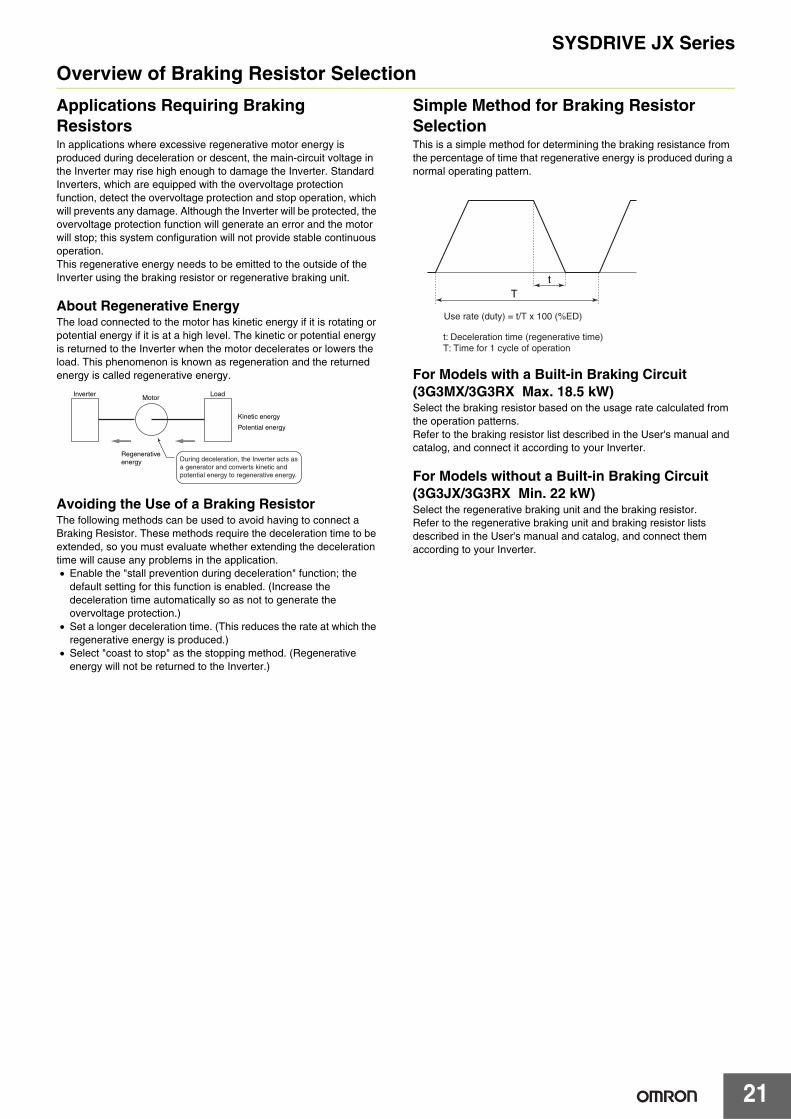
Overview of Braking Resistor Selection
Applications Requiring Braking ResistorsIn applications where excessive regenerative motor energy is produced during deceleration or descent, the main-circuit voltage in the Inverter may rise high enough to damage the Inverter. Standard Inverters, which are equipped with the overvoltage protection function, detect the overvoltage protection and stop operation, which will prevents any damage. Although the Inverter will be protected, the overvoltage protection function will generate an error and the motor will stop; this system configuration will not provide stable continuous operation.This regenerative energy needs to be emitted to the outside of the Inverter using the braking resistor or regenerative braking unit.
About Regenerative EnergyThe load connected to the motor has kinetic energy if it is rotating or potential energy if it is at a high level. The kinetic or potential energy is returned to the Inverter when the motor decelerates or lowers the load. This phenomenon is known as regeneration and the returned energy is called regenerative energy.
Avoiding the Use of a Braking ResistorThe following methods can be used to avoid having to connect a Braking Resistor. These methods require the deceleration time to be extended, so you must evaluate whether extending the deceleration time will cause any problems in the application.• Enable the "stall prevention during deceleration" function; the
default setting for this function is enabled. (Increase the deceleration time automatically so as not to generate the overvoltage protection.)
• Set a longer deceleration time. (This reduces the rate at which the regenerative energy is produced.)
• Select "coast to stop" as the stopping method. (Regenerative energy will not be returned to the Inverter.)
Simple Method for Braking Resistor SelectionThis is a simple method for determining the braking resistance from the percentage of time that regenerative energy is produced during a normal operating pattern.
For Models with a Built-in Braking Circuit (3G3MX/3G3RX Max. 18.5 kW)Select the braking resistor based on the usage rate calculated from the operation patterns.Refer to the braking resistor list described in the User's manual and catalog, and connect it according to your Inverter.
For Models without a Built-in Braking Circuit (3G3JX/3G3RX Min. 22 kW)Select the regenerative braking unit and the braking resistor.Refer to the regenerative braking unit and braking resistor lists described in the User's manual and catalog, and connect them according to your Inverter.
Inverter Load
Regenerativeenergy
Kinetic energy
Potential energy
Motor
During deceleration, the Inverter acts as a generator and converts kinetic and potential energy to regenerative energy.
Tt
Use rate (duty) = t/T x 100 (%ED)
t: Deceleration time (regenerative time)T: Time for 1 cycle of operation
SYSDRIVE JX Series
22
Detailed Method for Braking Resistor SelectionIf the Braking Resistor's use rate (duty factor) exceeds 10% ED or the application requires an extremely large braking torque, use the following method to calculate the regenerative energy and select a Braking Resistor.
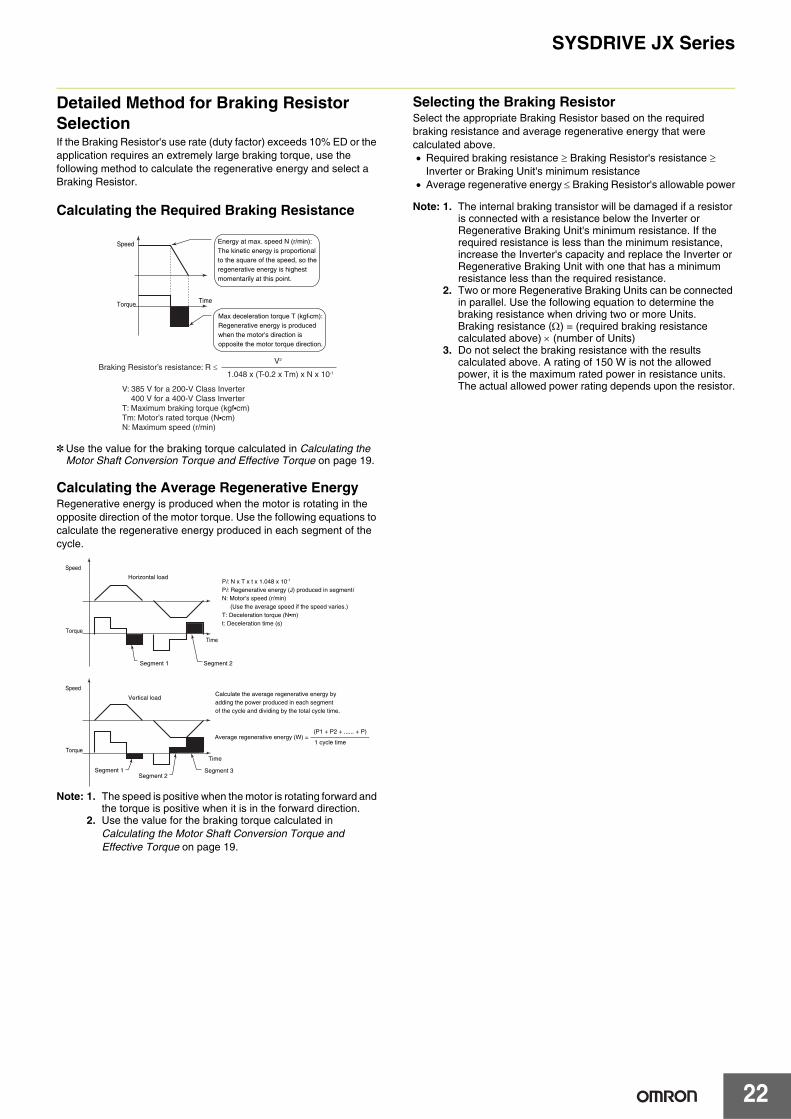
Calculating the Required Braking Resistance
* Use the value for the braking torque calculated in Calculating the Motor Shaft Conversion Torque and Effective Torque on page 19.
Calculating the Average Regenerative EnergyRegenerative energy is produced when the motor is rotating in the opposite direction of the motor torque. Use the following equations to calculate the regenerative energy produced in each segment of the cycle.
Note: 1. The speed is positive when the motor is rotating forward and the torque is positive when it is in the forward direction.
2. Use the value for the braking torque calculated in Calculating the Motor Shaft Conversion Torque and Effective Torque on page 19.
Selecting the Braking ResistorSelect the appropriate Braking Resistor based on the required braking resistance and average regenerative energy that were calculated above.• Required braking resistance ≥ Braking Resistor's resistance ≥
Inverter or Braking Unit's minimum resistance• Average regenerative energy ≤ Braking Resistor's allowable power
Note: 1. The internal braking transistor will be damaged if a resistor is connected with a resistance below the Inverter or Regenerative Braking Unit's minimum resistance. If the required resistance is less than the minimum resistance, increase the Inverter's capacity and replace the Inverter or Regenerative Braking Unit with one that has a minimum resistance less than the required resistance.
2. Two or more Regenerative Braking Units can be connected in parallel. Use the following equation to determine the braking resistance when driving two or more Units.Braking resistance (Ω) = (required braking resistance calculated above) × (number of Units)
3. Do not select the braking resistance with the results calculated above. A rating of 150 W is not the allowed power, it is the maximum rated power in resistance units. The actual allowed power rating depends upon the resistor.
Energy at max. speed N (r/min):The kinetic energy is proportionalto the square of the speed, so the regenerative energy is highest momentarily at this point.
Max deceleration torque T (kgf•cm):Regenerative energy is produced when the motor's direction is opposite the motor torque direction.
TimeTorque
Speed
Braking Resistor’s resistance: R ≤V2
1.048 x (T-0.2 x Tm) x N x 10-1
V: 385 V for a 200-V Class Inverter 400 V for a 400-V Class InverterT: Maximum braking torque (kgf•cm)Tm: Motor’s rated torque (N•cm)N: Maximum speed (r/min)
Segment 1 Segment 2
Horizontal load
Vertical load
Torque
Torque
Speed
Speed
Time
Segment 1Segment 2
Segment 3
Time
Pi: N x T x t x 1.048 x 10⁻¹
Pi: Regenerative energy (J) produced in segmentiN: Motor’s speed (r/min) (Use the average speed if the speed varies.)T: Deceleration torque (N•m)t: Deceleration time (s)
Calculate the average regenerative energy by adding the power produced in each segment of the cycle and dividing by the total cycle time.
Average regenerative energy (W) = (P1 + P2 + ...... + P)
1 cycle time