synthesisof color filter array pattern in digital...
TRANSCRIPT
Faculty of Computer Science Institute of Systems Architecture, Privacy and Data Security Research Group
Synthesis of Color Filter ArrayPattern in Digital Images
Matthias Kirchner and Rainer Böhme
{matthias.kirchner,rainer.boehme}@inf.tu-dresden.de
Media Forensics and Security XI
San Jose, CA · 2009/ 01/ 20
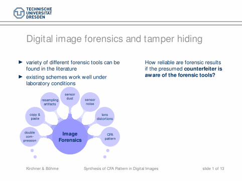
Digital image forensics and tamper hiding
◮ variety of different forensic tools can befound in the literature
◮ existing schemes work well underlaboratory conditions
Image
Forensics
lensdistortions
doublecom-
pression
copy &paste
resamplingartifacts
CFApattern
sensornoise
sensordust
How reliable are forensic resultsif the presumed counterfeiter isaware of the forensic tools?
Synthesis of CFA Pattern in Digital ImagesKirchner & Böhme slide 1 of 13
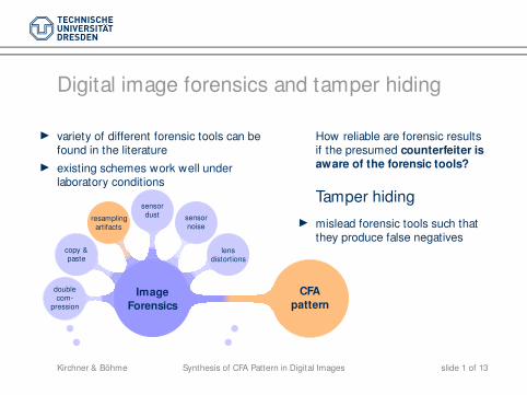
Digital image forensics and tamper hiding
◮ variety of different forensic tools can befound in the literature
◮ existing schemes work well underlaboratory conditions
Image
Forensics
lensdistortions
doublecom-
pression
copy &paste
CFA
pattern
resamplingartifacts
sensornoise
sensordust
How reliable are forensic resultsif the presumed counterfeiter isaware of the forensic tools?
Tamper hiding
◮ mislead forensic tools such thatthey produce false negatives
Synthesis of CFA Pattern in Digital ImagesKirchner & Böhme slide 1 of 13
1CFA Synthesis
Problem statement
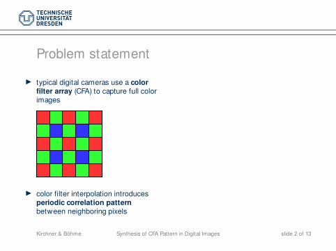
◮ typical digital cameras use a colorfilter array (CFA) to capture full colorimages
◮ color filter interpolation introducesperiodic correlation patternbetween neighboring pixels
Synthesis of CFA Pattern in Digital ImagesKirchner & Böhme slide 2 of 13
Problem statement
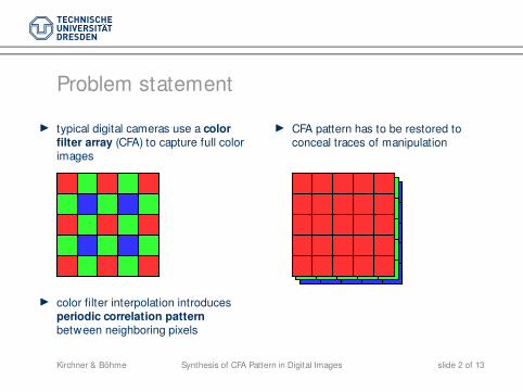
◮ typical digital cameras use a colorfilter array (CFA) to capture full colorimages
◮ CFA pattern has to be restored toconceal traces of manipulation
◮ color filter interpolation introducesperiodic correlation patternbetween neighboring pixels
Synthesis of CFA Pattern in Digital ImagesKirchner & Böhme slide 2 of 13
Problem statement
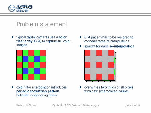
◮ typical digital cameras use a colorfilter array (CFA) to capture full colorimages
◮ CFA pattern has to be restored toconceal traces of manipulation
◮ straight-forward: re-interpolation
◮ color filter interpolation introducesperiodic correlation patternbetween neighboring pixels
◮ overwrites two thirds of all pixelswith new (interpolated) values
Synthesis of CFA Pattern in Digital ImagesKirchner & Böhme slide 2 of 13
A minimal distortion approach
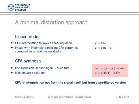
Linear model
◮ CFA interpolation follows a linear equation y = Hx
◮ image with incomplete/missing CFA pattern iscorrupted by an additive residual ǫ
y = Hx + ǫ
CFA synthesis
◮ find a possible sensor signal x such that ‖ǫ‖ = ‖y − y‖ → min
◮ least squares solution x = (H′H)−1H′y
CFA re-interpolation not from the signal itself, but from a pre-filtered version
Synthesis of CFA Pattern in Digital ImagesKirchner & Böhme slide 3 of 13
Structure of H
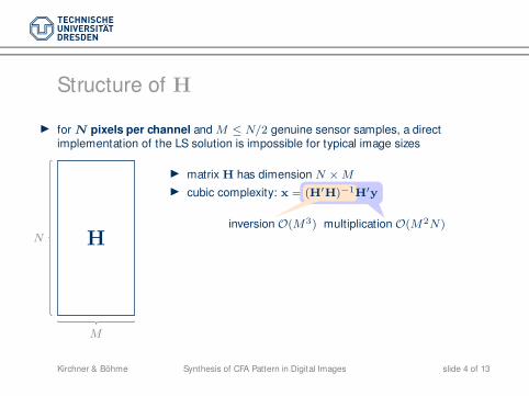
◮ for N pixels per channel and M ≤ N/2 genuine sensor samples, a directimplementation of the LS solution is impossible for typical image sizes
N
M
H
◮ matrix H has dimension N × M
◮ cubic complexity: x = (H′H)−1H′y
inversion O(M3) multiplication O(M2N)
Synthesis of CFA Pattern in Digital ImagesKirchner & Böhme slide 4 of 13
Structure of H
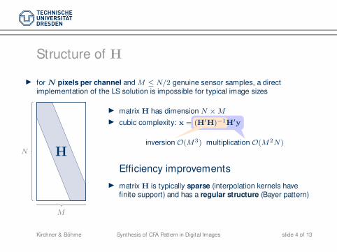
◮ for N pixels per channel and M ≤ N/2 genuine sensor samples, a directimplementation of the LS solution is impossible for typical image sizes
N
M
H
◮ matrix H has dimension N × M
◮ cubic complexity: x = (H′H)−1H′y
inversion O(M3) multiplication O(M2N)
Efficiency improvements
◮ matrix H is typically sparse (interpolation kernels havefinite support) and has a regular structure (Bayer pattern)
Synthesis of CFA Pattern in Digital ImagesKirchner & Böhme slide 4 of 13

2Red Channel
Partitioning H
=
b
b
A
1
1/2 1/2
1
1/2 1/2
1
1/2 1/2
1/4 1/4 1/4 1/4
1/2 1/2
1/4 1/4 1/4 1/4
1/2 1/2
1
1/2 1/2
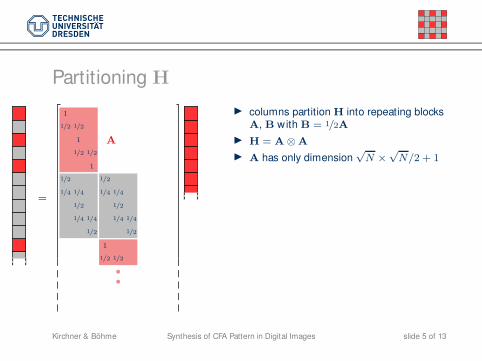
◮ columns partition H into repeating blocksA, B with B = 1/2A
◮ H = A ⊗ A
◮ A has only dimension√
N ×√
N/2 + 1
Synthesis of CFA Pattern in Digital ImagesKirchner & Böhme slide 5 of 13
Partitioning H
b
b
√N
1
1/2 1/2
1
1/2 1/2
1
1/2 1/2
1/4 1/4 1/4 1/4
1/2 1/2
1/4 1/4 1/4 1/4
1/2 1/2
1
1/2 1/2
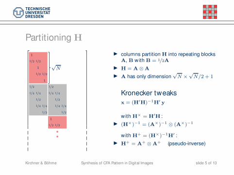
◮ columns partition H into repeating blocksA, B with B = 1/2A
◮ H = A ⊗ A
◮ A has only dimension√
N ×√
N/2 + 1
Kronecker tweaks
x = (H′H)−1H′ y
with H× = H′H :
◮ (H×)−1 = (A×)−1 ⊗ (A×)−1
with H+ = (H×)−1H′ :
◮ H+ = A+ ⊗ A+ (pseudo-inverse)
Synthesis of CFA Pattern in Digital ImagesKirchner & Böhme slide 5 of 13
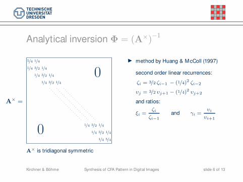
Analytical inversion Φ = (A×)−1
5/4 1/4
1/4 3/2 1/4
1/4 3/2 1/4
1/4 3/2 1/4
1/4 3/2 1/4
1/4 3/2 1/4
1/4 5/4
A×
=
0
0
A× is tridiagonal symmetric
◮ method by Huang & McColl (1997)
second order linear recurrences:
ζi = 3/2 ζi−1 − (1/4)2 ζi−2
υj = 3/2 υj+1 − (1/4)2 υj+2
and ratios:
ξi =ζi
ζi−1
and γi =υi
υi+1
Synthesis of CFA Pattern in Digital ImagesKirchner & Böhme slide 6 of 13
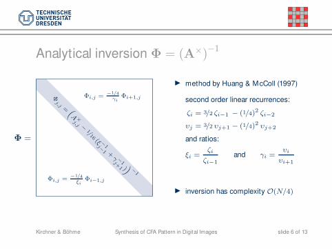
Analytical inversion Φ = (A×)−1
Φj,j = “
A ×j,j −
1/16 (ξ −
1j−1 +
γ −1j+1 )
”
−1
Φi,j =−1/4
ξi
Φi−1,j
Φi,j = −1/4γi
Φi+1,j
Φ =
◮ method by Huang & McColl (1997)
second order linear recurrences:
ζi = 3/2 ζi−1 − (1/4)2 ζi−2
υj = 3/2 υj+1 − (1/4)2 υj+2
and ratios:
ξi =ζi
ζi−1
and γi =υi
υi+1
◮ inversion has complexity O(N/4)
Synthesis of CFA Pattern in Digital ImagesKirchner & Böhme slide 6 of 13
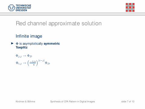
Red channel approximate solution
Infinite image
◮ Φ is asymptotically symmetricToeplitz
Φj,j → ΦD
Φi,j →“
−1/4q
”|i−j|ΦD
Synthesis of CFA Pattern in Digital ImagesKirchner & Böhme slide 7 of 13
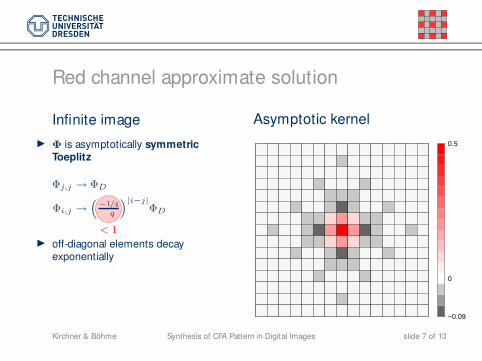
Red channel approximate solution
Infinite image
◮ Φ is asymptotically symmetricToeplitz
Φj,j → ΦD
Φi,j →“
−1/4q
”|i−j|ΦD
−1/4q
< 1◮ off-diagonal elements decay
exponentially
Asymptotic kernel
0.5
0
−0.09
Synthesis of CFA Pattern in Digital ImagesKirchner & Böhme slide 7 of 13

3Green Channel
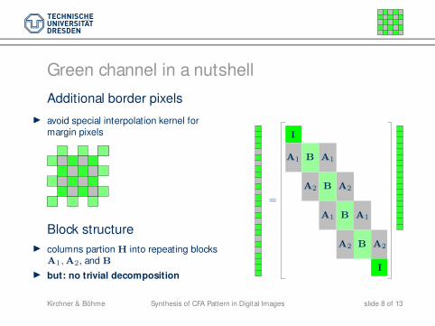
Green channel in a nutshell
Additional border pixels
◮ avoid special interpolation kernel formargin pixels
Block structure
◮ columns partion H into repeating blocksA1, A2, and B
◮ but: no trivial decomposition
I
B
B
B
B
A1
A1
A1
A1
A2
A2
A2
A2
I
=
Synthesis of CFA Pattern in Digital ImagesKirchner & Böhme slide 8 of 13
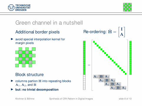
Green channel in a nutshell
Additional border pixels
◮ avoid special interpolation kernel formargin pixels
Block structure
◮ columns partion H into repeating blocksA1, A2, and B
◮ but: no trivial decomposition
Re-ordering: H =
[
I
A
]
B
B
B
B
A1
A1
A1
A1
A2
A2
A2
A2
=
Synthesis of CFA Pattern in Digital ImagesKirchner & Böhme slide 8 of 13
4Experimental Results
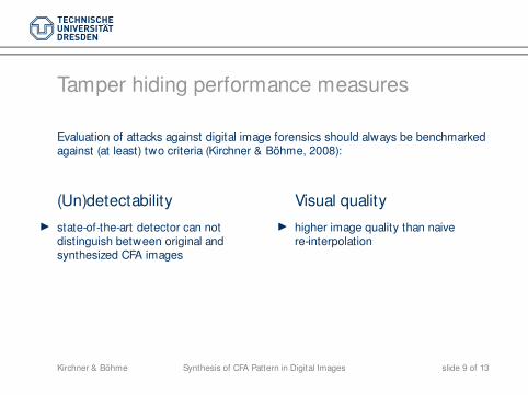
Tamper hiding performance measures
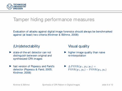
Evaluation of attacks against digital image forensics should always be benchmarkedagainst (at least) two criteria (Kirchner & Böhme, 2008):
(Un)detectability
◮ state-of-the-art detector can notdistinguish between original andsynthesized CFA images
Visual quality
◮ higher image quality than naivere-interpolation
Synthesis of CFA Pattern in Digital ImagesKirchner & Böhme slide 9 of 13
Tamper hiding performance measures
Evaluation of attacks against digital image forensics should always be benchmarkedagainst (at least) two criteria (Kirchner & Böhme, 2008):
(Un)detectability
◮ state-of-the-art detector can notdistinguish between original andsynthesized CFA images
Visual quality
◮ higher image quality than naivere-interpolation
◮ fast version of Popescu and Farid’sdetector (Popescu & Farid, 2005;Kirchner, 2008)
◮ ∆PSNR(y1, y2;y0) =PSNR(y1,y0) − PSNR(y2, y0)
Synthesis of CFA Pattern in Digital ImagesKirchner & Böhme slide 9 of 13
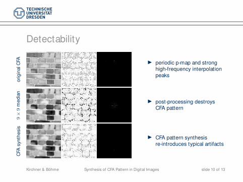
Detectability
ori
gin
alC
FA ◮ periodic p-map and stronghigh-frequency interpolationpeaks
9×
9m
ed
ian
◮ post-processing destroysCFA pattern
CFA
syn
the
sis
◮ CFA pattern synthesisre-introduces typical artifacts
Synthesis of CFA Pattern in Digital ImagesKirchner & Böhme slide 10 of 13
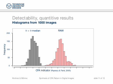
Detectability, quantitive resultsHistograms from 1000 images
0
50
100
150
200
fre
qu
en
cy
CFA indicator (Popescu & Farid, 2005)
9 × 9 median RAW
Synthesis of CFA Pattern in Digital ImagesKirchner & Böhme slide 11 of 13
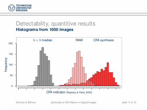
Detectability, quantitive resultsHistograms from 1000 images
0
50
100
150
200
fre
qu
en
cy
CFA synthesis
CFA indicator (Popescu & Farid, 2005)
9 × 9 median RAW
Synthesis of CFA Pattern in Digital ImagesKirchner & Böhme slide 11 of 13

Detectability, quantitive resultsHistograms from 1000 images
0
50
100
150
200
fre
qu
en
cy
CFA synthesis
CFA indicator (Popescu & Farid, 2005)
9 × 9 median RAW
CFA interpolation not the lastin-camera processing step!
Synthesis of CFA Pattern in Digital ImagesKirchner & Böhme slide 11 of 13
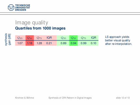
Image qualityQuartiles from 1000 images
syn
the
sis
gain
[dB
]
Q25 Q50 Q75 IQR Q25 Q50 Q75 IQR
1.07 1.18 1.28 0.21 0.89 0.94 0.99 0.10
LS approach yieldsbetter visual qualityafter re-interpolation.
Synthesis of CFA Pattern in Digital ImagesKirchner & Böhme slide 12 of 13
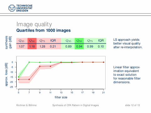
Image qualityQuartiles from 1000 images
syn
the
sis
gain
[dB
]
Q25 Q50 Q75 IQR Q25 Q50 Q75 IQR
1.07 1.18 1.28 0.21 0.89 0.94 0.99 0.10
LS approach yieldsbetter visual qualityafter re-interpolation.
-25
-20
-15
-10
-5
0
filter size
ap
pro
x.
loss
[dB
]
b
b b b b b b b b
b b
b b
b b b b b
5 7 9 11 13 15 17 19 21
Linear filter approx-imation equivalentto exact solutionfor reasonable filterdimensions.
Synthesis of CFA Pattern in Digital ImagesKirchner & Böhme slide 12 of 13
5Conclusion
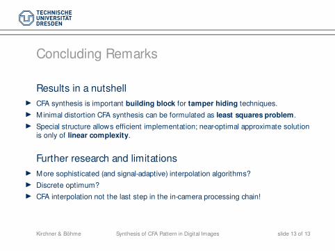
Concluding Remarks
Results in a nutshell
◮ CFA synthesis is important building block for tamper hiding techniques.
◮ Minimal distortion CFA synthesis can be formulated as least squares problem.
◮ Special structure allows efficient implementation; near-optimal approximate solutionis only of linear complexity.
Further research and limitations
◮ More sophisticated (and signal-adaptive) interpolation algorithms?
◮ Discrete optimum?
◮ CFA interpolation not the last step in the in-camera processing chain!
Synthesis of CFA Pattern in Digital ImagesKirchner & Böhme slide 13 of 13

Faculty of Computer Science Institute of Systems Architecture, Privacy and Data Security Research Group
Thanks for your attention
Questions?
Matthias Kirchner and Rainer Böhme
{matthias.kirchner,rainer.boehme}@inf.tu-dresden.de
The first author gratefully receives a doctorate scholarship fromDeutsche Telekom Stiftung, Bonn, Germany.
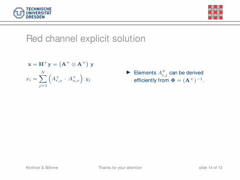
Red channel explicit solution
x = H+y =`
A+ ⊗ A+´
y
xi =N
X
j=1
“
A+r,s · A+
u,v
”
yj
◮ Elements A+
i,j can be derived
efficiently from Φ = (A×)−1.
Thanks for your attentionKirchner & Böhme slide 14 of 13
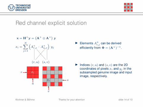
Red channel explicit solution
x = H+y =`
A+ ⊗ A+´
y
xi =N
X
j=1
“
A+r,s · A+
u,v
”
yj
(r, u) (s, v)
xir
uyj s
v
◮ Elements A+
i,j can be derived
efficiently from Φ = (A×)−1.
◮ Indices (r, u) and (s, v) are the 2Dcoordinates of pixels xi and yj in thesubsampled genuine image and inputimage, respectively.
Thanks for your attentionKirchner & Böhme slide 14 of 13
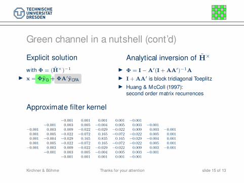
Green channel in a nutshell (cont’d)
Explicit solution
with Φ = (H×)−1
◮ x = ΦyG + ΦA′yCFA
Analytical inversion of H×
◮ Φ = I − A′(I + AA′)−1A
◮ I + AA′ is block tridiagonal Toeplitz
◮ Huang & McColl (1997):second order matrix recurrences
Approximate filter kernel
−0.001 0.001 0.001 0.001 −0.001−0.001 0.003 0.005 −0.004 0.005 0.003 −0.001
−0.001 0.003 0.009 −0.022 −0.029 −0.022 0.009 0.003 −0.0010.001 0.005 −0.022 −0.072 0.165 −0.072 −0.022 0.005 0.0010.001 −0.004 −0.029 0.165 0.835 0.165 −0.029 −0.004 0.0010.001 0.005 −0.022 −0.072 0.165 −0.072 −0.022 0.005 0.001
−0.001 0.003 0.009 −0.022 −0.029 −0.022 0.009 0.003 −0.001−0.001 0.003 0.005 −0.004 0.005 0.003 −0.001
−0.001 0.001 0.001 0.001 −0.001
Thanks for your attentionKirchner & Böhme slide 15 of 13