synthesis and characterization of thermally stable mcm-41/γ-al2o3 composite materials
TRANSCRIPT

www.elsevier.com/locate/micromeso
Microporous and Mesoporous Materials 94 (2006) 254–260
Synthesis and characterization of thermally stableMCM-41/c-Al2O3 composite materials
Weili Huang a, Baijun Liu a,*, Famin Sun b, Zhihua Zhang b, Xiaojun Bao a,*
a The Key Laboratory of Catalysis, China National Petroleum Co., China University of Petroleum, Beijing 102249, PR Chinab Research Institute of Daqing Petrochemical Company, PetroChina Company, Ltd., Daqing City, Heilongjiang 163714, PR China
Received 3 December 2004; received in revised form 16 March 2006; accepted 24 March 2006Available online 19 May 2006
Abstract
A thermally stable MCM-41/c-Al2O3 composite (‘‘Composite 2’’) was obtained by in situ synthesis using boehmite, a hydratedc-Al2O3, and compared to a MCM-41/c-Al2O3 composite (‘‘Composite 1’’) made using pure c-Al2O3. The two composites were studiedby means of X-ray diffraction (XRD), X-ray fluorescence (XRF), scanning electron microscopy (SEM), laser particle size analyzer, trans-mission electron microscopy (TEM), high-resolution transmission electron microscopy (HRTEM) equipped with energy dispersive X-rayspectroscopy (EDS), and nitrogen adsorption isotherm measurements. The results showed that with boehmite as the initial material, thethermal stability of the MCM-41 in Composite 2 was greatly improved and thus its specific surface area and pore volume were signif-icantly increased. It was also found that in the two composites MCM-41 grew in two different mechanisms: in Composite 1 MCM-41grew on the outer surface of c-Al2O3 or occurred as non-in situ crystallization product, whereas in Composite 2 MCM-41 overgrew onlyon the internal surface of boehmite grains.� 2006 Elsevier Inc. All rights reserved.
Keywords: MCM-41/c-Al2O3 composite; In situ synthesis; Hydration; Thermal stability
1. Introduction
MCM-41, a mesoporous material with hexagonal arrayof uniform mesopores and large specific surface area, hasattracted considerable attention in physics, chemistry,materials science, and other relevant areas in recent years[1–4]. MCM-41 can be used in many acid-catalyzed reac-tions because of its unique structure and properties [5],especially in converting molecules of large size such asheavy oil molecules [6]. Numerous results obtained onCo–Mo hydrodesulfurization (HDS) catalysts supportedon alumina with different amounts of MCM-41 showedthat the incorporation of MCM-41 could significantlydecrease the interaction between Co and Mo phases andthe support, leading to higher catalyst activity for the
1387-1811/$ - see front matter � 2006 Elsevier Inc. All rights reserved.
doi:10.1016/j.micromeso.2006.03.033
* Corresponding authors. Tel.: +86 10 8973 3751; fax: +86 10 8973 4979.E-mail addresses: [email protected] (B. Liu), [email protected] (X.
Bao).
HDS reaction of 4,6-dibenzothiophenes (4,6-DBT) [7,8].It was also found that for vacuum gas oil hydrocracking,MCM-41 supported catalysts could give high middle distil-lates selectivity because of its weak to moderate acidity,well-defined mesopores and high surface area [9–11]. How-ever, the poor thermal- and hydrothermal-stability andweak acidity of MCM-41 limit its industrial applicationsthat may involve severe operating conditions or needstrong acidity, such as in the fluid catalytic cracking(FCC) of heavy petroleum residua [12].
Extensive efforts have been dedicated to improvingthermal- and hydrothermal-stabilities of MCM-41. Therequirement for the thermal- and hydrothermal-stabilitiesof MCM-41 depends on different applications. Some in-dustrial processes, e.g., FCC of heavy petroleum residua,involve the operations that frequently expose catalysts tohigh temperature steam in riser reactors and to hightemperature oxidizing atmosphere in regenerators, so boththermal- and hydrothermal-stabilities of the catalysts are

W. Huang et al. / Microporous and Mesoporous Materials 94 (2006) 254–260 255
needed. For some applications, e.g., hydrogenation ofpetroleum products and fine chemicals, the feedstocks tohydrogenation units contain only trace-amount of waterand the catalysts are seldom exposed to high temperaturesteam, thus the only imposed requirement for the catalystsis their thermal stability for regeneration. To improve thethermal stability of MCM-41, the present investigationdeveloped an in situ synthesis technique by overgrowingMCM-41 on the surface of boehmite, a hydration productof c-Al2O3. It is hoped that by increasing the wall thicknessof MCM-41, a thermally stable MCM-41/c-Al2O3 compos-ite that may be directly used as catalyst supports can beobtained.
2. Experimental
2.1. Synthesis
c-Al2O3 (97%, Shandong Branch, China AluminumIndustry Co., Ltd.) and deionized water were added to aTeflon-lined stainless-steel autoclave for hydration at150 �C for 24 h. Cetyltrimethyl ammonium bromide(CH3(CH2)15N(CH3)3Br) (CTMABr, 99%, Beijing Chemi-cal Reagents Company) was added to the hydration prod-uct and agitated at 35 �C for 1 h, then water glass (20 wt%SiO2, Lanzhou PetroChemical Co., PetroChina Company,Ltd.) and 2 M H2SO4 were added to adjust the pH value ofthe system to 11.0, and finally a hydrogel with a molarcomposition of 5SiO2:2.1Al2O3:1CTMABr:462H2O wasobtained. After aged under agitation at 35 �C for 3 h, thehydrogel was placed in a static autoclave at 150 �C for24 h, then cooled down to room temperature, and finallyseparated by filtrating, followed with washing and dryingat 110 �C overnight, the solid product MCM-41/c-Al2O3
could be recovered. The as-synthesized product (Compos-ite 2) was then calcined at 550 �C in air for 6 h with a heat-ing rate of 2 �C/min. For comparison, the other MCM-41/c-Al2O3 composite (Composite 1) was synthesized with thesame procedure except for directly using c-Al2O3 instead ofits hydration product as the initial material.
The calcined samples were heated to 900 �C in air for 2 hwith a heating rate of 10 �C/min, and their thermal stabilitywere examined by comparing the integral X-ray diffraction(XRD) peak intensity of the synthesized samples beforeand after thermal treatment on (100) plane with that ofthe reference material, a MCM-41/c-Al2O3 composite syn-thesized in the present study, in which MCM-41 has thehighest integral peak intensity on (100) plane.
2.2. Characterization
XRD measurements were performed on a ShimadzuXRD-6000 X-ray diffractometer using Ni-filtered Cu Ka
radiation operated at 40 kV and 30 mA. The 2h angles inthe low angle range of 1.6–6� were scanned at a speed of1�/min with the slit parameters of DS = 0.5�, SS = 1� andRS = 0.30 mm. The 2h angles in the high angle range were
scanned from 10� to 70� at a speed of 4�/min with the slitparameters of DS = SS = 1� and RS = 0.30 mm. The cal-culations of the unit cell lattice a0 and pore wall thicknessof MCM-41 can be referred to the literature [1]. A mechan-ical mixture of c-Al2O3 and MCM-41 with the same massfraction of SiO2 as the two MCM-41/c-Al2O3 compositeshave was prepared and used as the reference material.The crystallinity of MCM-41 in the reference material istaken as 100%. The relative crystallinity of MCM-41 inthe two MCM-41/c-Al2O3 composites can be obtained bycomparing their intensities of the diffraction peaks at2h = 2.2� with that of the reference material.
The elemental analyses of the samples were conductedby a Rigaku ZSX 100e X-ray fluorescence (XRF) spec-trometer. The quantitatively results were used to calculaten(Al)/n(Si) of the samples.
Scanning electron microscopy (SEM) measurementswere performed on a LEO 435VP scanning electron micro-scope operated at 20 kV. Prior to the measurement, thesamples were coated with a thin layer of gold.
Particle size distributions of the samples were carriedout using a Malvern Zeta Sizer Nano ZS. Prior to themeasurement, the samples were dispersed in water withan ultrasonic machine.
Transmission electron microscopy (TEM) measure-ments were performed on a JEOL JEM-2000FX II trans-mission electron microscope operated at 120 kV. Prior tothe measurement, the samples were mounted on a car-bon-coated copper grid by drying a droplet of a suspensionof the ground sample in ethanol on the grid.
High-resolution transmission electron microscopy(HRTEM) analysis of Composite 2 was taken from aJEOL JEM-2010 transmission electron microscopeequipped with an energy dispersive spectrometer (Link-Inca) using an ultra-thin window. The microscope wasoperated at 200 kV with 0.19 nm point resolution. Thesample preparation for HRTEM and EDS analysesincludes four steps: monolayer dispersion, embedment,mechanical polishing and Ar ion sputtering.
Nitrogen adsorption measurements were performed at�196 �C on a Micromeritics ASAP 2020 volumetricadsorption analyzer. Prior to the measurements, thehydration product of c-Al2O3 was degassed at 250 �C for7 h, and other samples were degassed under vacuum at350 �C for 5 h. Surface areas, SBET, were calculated usingthe BET equation based on the adsorption data in the rel-ative pressure range of 0.05–0.25 [13]. The pore size distri-butions (PSD) were calculated from the desorptionbranches of the isotherms using the Barrett–Joyner–Hal-enda (BJH) method [14].
3. Results and discussion
3.1. XRD and XRF
The XRD patterns of the calcined Composites 1 and 2are shown in Fig. 1. In the low-angle 2h region

2 3 4 5 6 7
(200)(110)
(100)
Composite 2Composite 1
Inte
nsity
(cps
)
2θ (degrees)
2θ (degrees)
(A)
10 20 30 40 50 60 70 80 90
Inte
nsity
(cps
)
γ-alumina
Composite 2
Composite 1
(B)
Fig. 1. XRD patterns of c-Al2O3 and MCM-41/c-Al2O3 composites.
2 3 4 5 6 7
(200)(110)
(100)
Composite 2
Composite 1
Inte
nsity
(cps
)
2θ (degrees)
Fig. 2. XRD patterns of the composites after thermal treatment.
256 W. Huang et al. / Microporous and Mesoporous Materials 94 (2006) 254–260
(Fig. 1(A)), both Composites 1 and 2 exhibit three reflec-tions on (10 0), (110) and (200) planes that are typical tothe mesoporous molecular sieves with hexagonal symmetry[1], indicating that MCM-41 phase exists in the twocomposites with their relative crystallinity at 33.1% and135.0%, respectively. As shown in Table 1, the unit cellparameter and pore size of MCM-41 in Composite 2 are0.21 nm and 0.06 nm larger than those of MCM-41 inComposite 1, respectively, signifying that the pore wall ofMCM-41 in Composite 2 synthesized using boehmite asthe initial materials is 0.15 nm thicker than that ofMCM-41 in Composite 1. In the high-angle 2h region(Fig. 1(B)), both Composites 1 and 2 show the diffraction
Table 1Structural properties of the samples
Sample Bulkn(Si)/n(Al)
a0
(nm)Pore diameter(nm)
Wall thic(nm)
Composite 1 1.22 4.18 2.50 1.68Composite 2 1.26 4.39 2.56 1.83c-Al2O3 0 – – –Boehmite 0 – – –
peaks at 38.6�, 44.6�, and 66.7�, respectively, due to the for-mation of c-Al2O3, but Composite 2 exhibits higher andsharper diffraction peaks of c-Al2O3 than Composite 1,being attributed to the well-crystallized c-Al2O3 resultingfrom the well-crystallized boehmite formed during c-Al2O3 hydration [15], as shown as follows:
Al2O3c-alumina
��!H2O2AlOðOHÞ
well-crystallized boehmite
���!�H2OAl2O3c-alumina
ð1Þ
After calcined at 900 �C for 2 h in air, Composite 1 losesall the diffraction peaks that are specific to MCM-41, indi-cating the collapse of mesoporous channels (Fig. 2). Afterthe same thermal treatment condition, however, Composite2 still maintains its relative crystallinity at around 98.6%(Fig. 2). One possible mechanism for the improvement inthe thermal stability by substituting c-Al2O3 with boehmiteis much less dissolution of boehmite than that of c-Al2O3 inthe synthesis procedure of MCM-41 [16]. In the solutionwith high concentration alkaline sodium, AlðOHÞ�4 is theonly aluminum-bearing species [16]. AlðOHÞ�4 is incorpo-rated into the framework of mesoporous MCM-41 by iso-morphous substitution of aluminum atom for silicon atomduring hydrothermal synthesis [17]. The less introductionof AlðOHÞ�4 to the synthesis system results in thicker porewall and higher framework n(Si)/n(Al) of MCM-41 [18], i.e.,higher thermal stability, since the dealumination of MCM-41 during high temperature treatment is responsible for itsframework disruption.
kness Surface area(m2/g)
Pore volume(cm3/g)
Average pore size(nm)
520 0.55 3.21849 0.77 3.32295 0.89 10.1673 0.48 24.98
10 100 1000 100000
20
40
60
80
Volu
me
(%)
Diameter (nm)
A: γ-Al2O3
B: Composite 1 C: Composite 2 D: Boehmite A
BC
D
Fig. 4. Particle size distributions of the samples.
W. Huang et al. / Microporous and Mesoporous Materials 94 (2006) 254–260 257
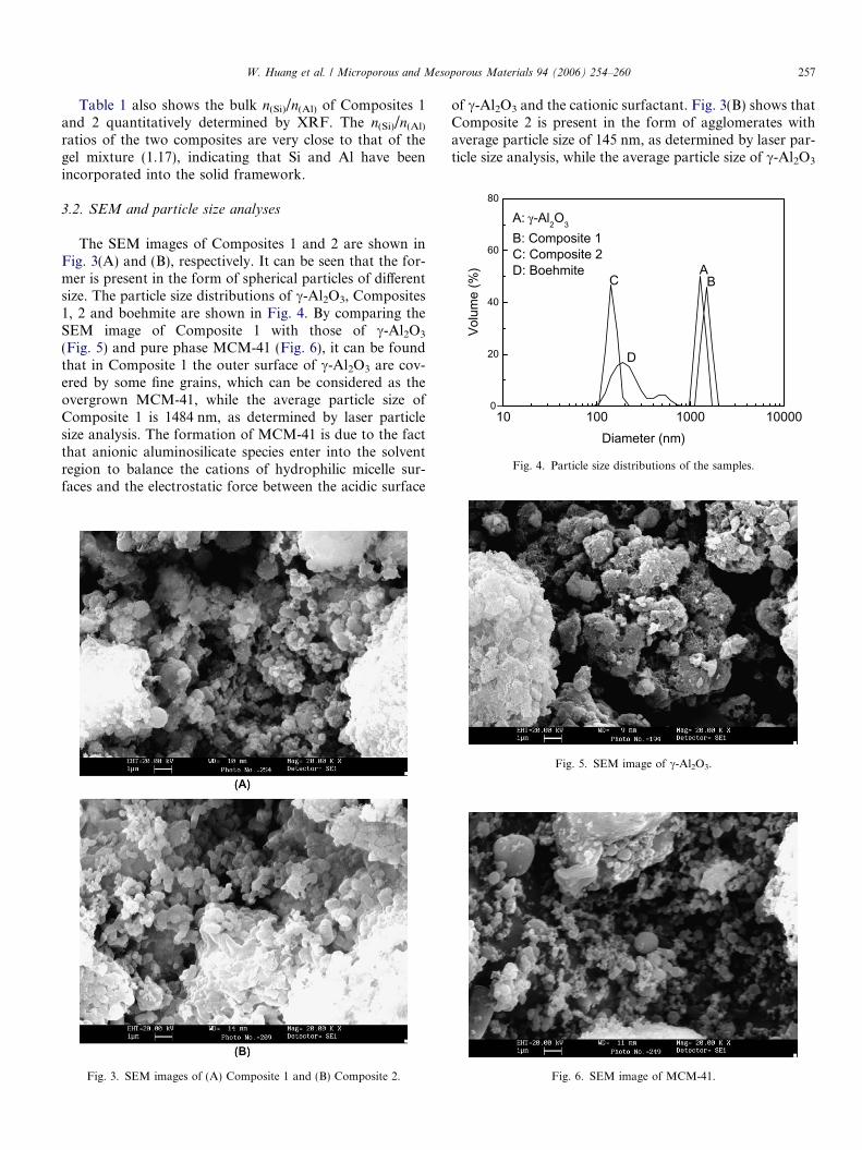
Table 1 also shows the bulk n(Si)/n(Al) of Composites 1and 2 quantitatively determined by XRF. The n(Si)/n(Al)
ratios of the two composites are very close to that of thegel mixture (1.17), indicating that Si and Al have beenincorporated into the solid framework.
3.2. SEM and particle size analyses
The SEM images of Composites 1 and 2 are shown inFig. 3(A) and (B), respectively. It can be seen that the for-mer is present in the form of spherical particles of differentsize. The particle size distributions of c-Al2O3, Composites1, 2 and boehmite are shown in Fig. 4. By comparing theSEM image of Composite 1 with those of c-Al2O3
(Fig. 5) and pure phase MCM-41 (Fig. 6), it can be foundthat in Composite 1 the outer surface of c-Al2O3 are cov-ered by some fine grains, which can be considered as theovergrown MCM-41, while the average particle size ofComposite 1 is 1484 nm, as determined by laser particlesize analysis. The formation of MCM-41 is due to the factthat anionic aluminosilicate species enter into the solventregion to balance the cations of hydrophilic micelle sur-faces and the electrostatic force between the acidic surface
Fig. 3. SEM images of (A) Composite 1 and (B) Composite 2.
of c-Al2O3 and the cationic surfactant. Fig. 3(B) shows thatComposite 2 is present in the form of agglomerates withaverage particle size of 145 nm, as determined by laser par-ticle size analysis, while the average particle size of c-Al2O3
Fig. 5. SEM image of c-Al2O3.
Fig. 6. SEM image of MCM-41.

Fig. 7. SEM image of boehmite obtained by hydrating c-Al2O3 at 150 �Cfor 24 h.
258 W. Huang et al. / Microporous and Mesoporous Materials 94 (2006) 254–260
is 1281 nm. To understand what happened to c-Al2O3 afterhydration at 150 �C for 24 h, the hydration product is
Fig. 8. TEM images of (A) c-Al2O3, (B) Compo
filtrated and dried at 110 �C, then its morphology isexamined by SEM and the result is shown in Fig. 7. It isobserved that the primary boehmite grains are present withaverage particle size of 192 nm.
3.3. TEM and HRTEM analyses
The TEM images of c-Al2O3 and Composite 1(Fig. 8(A) and (B)) reveal that MCM-41 phase grows withits channels stretching to various directions and surroundsthe c-Al2O3 phase, indicating that due to the asymmetry ofthe outer surface of c-Al2O3, MCM-41 tends to overgrowon the sites with high surface free energy and small spaceobstruction. The TEM image of boehmite (Fig. 8(C)) indi-cates that boehmite is present in the form of aggregatedparticles with size of ca. 100–200 nm, consistent with theresults of the SEM and laser particle size analyses, whilethe TEM image of Composite 2 (Fig. 8(D)) illustrates thatsome agglomerates exist. In order to obtain detailed struc-tural information of Composite 2, its HRTEM image is
site 1, (C) boehmite, and (D) Composite 2.

Fig. 9. HRTEM image of Composite 2.
W. Huang et al. / Microporous and Mesoporous Materials 94 (2006) 254–260 259
obtained on a HRTEM equipped with EDS and is shownin Fig. 9. It can be seen that in the elliptic slice some darkparticles are embedded into the light material, and in somedark regions there exist some parallel sticks, as pointed bythe arrowhead. The EDS analysis results show that thesedark particles have their n(Si)/n(Al) at about 3.1 and thusare considered to be MCM-41, so the pore wall thicknessand pore channel size of MCM-41 can be visually resolved.Obviously, the MCM-41/c-Al2O3 composite synthesized inthe present study is assembled by two kinds of nano-scaleparticles, in this case it is difficult to obtain MCM-41 withlong-range order. It should be noted that the accuratedetermination of n(Si)/n(Al) of MCM-41 in Composite 2 isalso difficult because the measurement region of EDS is lar-ger than the size of the MCM-41 particles.
3.4. Nitrogen adsorption isotherms
The nitrogen adsorption isotherms of Composites 1 and2 are shown in Fig. 10. It can be seen that Composites 1and 2 exhibit type IV isotherms that are specific to
0.0 0.1 0.2 0.3 0.4 0.5 0.6 0.7 0.8 0.9 1.00
100
200
300
400
500
600
Volu
me
adso
rbed
(cm
3 /g S
TP)
Relative pressure (P/P0 )
Adsorbed Desorbed Composite 2
Composite 1
Fig. 10. Nitrogen adsorption isotherms of Composites 1 and 2.
mesoporous materials [19], although a significant differencein their isotherms exists.
The significant adsorption of Composites 1 and 2 at lowrelative pressure (P/P0 < 0.25) is most probably due tomonolayer coverage of the pore walls by nitrogen. It isfound that at P/P0 ranging from 0.05 to 0.25, Composite2 has higher nitrogen adsorption amount, and its BET spe-cific surface area calculated within the P/P0 range canreach up to 849 m2/g, much higher than 520 m2/g of Com-posite 1. With P/P0 ranging from 0.25 to 0.34, a sharpinflection in adsorption isotherms for both of the two com-posites, especially for Composite 2, occurs, indicating thecapillary condensation in the primary mesopores that aretypical to mesostructured materials with uniform pores[20]. It is well-known that the inflection point on adsorp-tion–desorption isotherms is related to the diameter ofthe mesopore and the step sharpness indicates the unifor-mity of the pore size distributions [21]. Based on thedesorption branches of the isotherms, the pore sizes ofMCM-41 in Composites 1 and 2 calculated by using theBJH method are 2.50 and 2.56 nm, respectively, as givenin Table 1. The sharper inflection of the isotherms of Com-posite 2 indicates the existence of more abundant mesop-ores and narrower pore size distribution in Composite 2than in Composite 1 [13]. The hysteresis loops of the twocomposites appearing with the relative pressure P/P0 rang-ing from 0.45 to 0.9 can be attributive to the consequenceof filling of nitrogen in the textural mesopores of the sizearound 3.8 nm [22,23], while the relatively smaller hystere-sis loop for Composite 2 is due to the less amount of amor-phous silica–alumina and the higher size uniformity of themesopores. The final increases in nitrogen volumeabsorbed at P/P0 > 0.9 for both composites indicate thatthe inter-particle macropores are filled at high relativepressures.
The PSDs of Composites 1, 2, c-Al2O3 and boehmiteobtained by hydrating c-Al2O3 at 150 �C for 24 h areshown in Fig. 11. Compared with that of c-Al2O3, thePSD of boehmite significantly shifts to larger pores, giving
1 10 100
0
1
2
3
4
5
6 Composite-1 Composite-2γ-Al2O3
Boehmite
Pore
vol
ume
(cm
3 /g)
Pore size (nm)
Fig. 11. Pore size distributions of the samples.

260 W. Huang et al. / Microporous and Mesoporous Materials 94 (2006) 254–260
an average pore size of 24.98 nm, as shown in Table 1. Thedistinct difference between c-Al2O3 and boehmite in theirPSDs can be attributive to the dramatic changes in the sizeand morphology of c-Al2O3 before and after hydration, asshown in Figs. 6 and 7. It is interesting to note that thePSDs of Composites 1 and 2 do not inherit any character-istics that are attributive to c-Al2O3 and boehmite,although both c-Al2O3 and boehmite are used as the initialmaterials for the synthesis of the two composites. In Com-posite 1, the pore channels of c-Al2O3 are occupied byamorphous silica–alumina due to the fact that the hexago-nal liquid-crystals of CTMABr cannot be accommodatedin the small pores of c-Al2O3 and only amorphous silica-alumina is formed by Si species and Al species that haveentered into the pore channels of c-Al2O3. Consequently,the pores that originally belong to c-Al2O3 disappear afterthe synthesis. For Composite 2, MCM-41 grows on theinternal surface of boehmite and fills up the pore channelsof boehmite, as shown in Fig. 9.
4. Conclusions
A thermally stable MCM-41/c-Al2O3 composite (Com-posite 2) was obtained by in situ synthesis over boehmite,a hydration product of c-Al2O3, and compared to theother MCM-41/c-Al2O3 composite (Composite 1) directlysynthesized over c-Al2O3 in the present investigation.The results showed that the thermal stability of MCM-41in MCM-41/c-Al2O3 composites could be remarkablyimproved by using boehmite as the initial material insteadof c-Al2O3. By this way, the relative crystallinity of theMCM-41 in the MCM-41/c-Al2O3 composite couldreached up to 98.6% even after thermal treatment at900 �C for 2 h, which is contributive to the existence of lessstructural framework Al species and increased wall thick-ness of MCM-41 in Composite 2. The characterizationresults of SEM, TEM, HRTEM and nitrogen adsorptionisotherm analyses confirmed that in Composite 2 MCM-41 overgrew on the internal surface of boehmite grains,resulting in the disappearance of the pore size distributionof the c-Al2O3 phase. In addition to its high thermal stabil-ity, Composite 2 also has higher specific surface area, larger
pore volume, and improved pore size distribution com-pared to Composite 1.
Acknowledgement
The financial support by the National Basic ResearchProgram of China (Grant No. 2004CB217805) is gratefullyacknowledged.
References
[1] C.T. Kresge, M.E. Leonowicz, W.J. Roth, J.C. Vartuli, J.S. Beck,Nature 359 (1992) 710.
[2] Y.T. Liao, L. Zang, D.L. Akins, Catal. Commun. 6 (2005) 141.[3] N. Lang, A. Tuel, Micropor. Mesopor. Mater. 77 (2005) 147.[4] Q.H. Zhang, W. Yang, X.X. Wang, Y. Wang, T. Shishido, K.
Takehira, Micropor. Mesopor. Mater. 77 (2005) 223.[5] J.H. Kim, M. Tanabe, M. Niwa, Micropor. Mater. 10 (1997) 85.[6] A. Corma, A. Martınez, V. Martınez-Soria, J.B. Monton, J. Catal.
153 (1995) 25.[7] M.J. Cheng, F. Kumata, T. Saito, T. Komatsu, T. Yashima, Appl.
Catal. A 183 (1999) 199.[8] J. Ramırez, R. Contreras, P. Castillo, T. Klimova, R. Zarate, R.
Luna, Appl. Catal. A 197 (2000) 69.[9] F.A. Barbosa, A.C.B.D. Santos, M.I.P.D. Silva, Catal. Today 98
(2004) 109.[10] S.P. Elangovan, M. Hartmann, J. Catal. 217 (2003) 388.[11] A. Corma, A. Martinez, V. Martinezsoria, J.B. Monton, J. Catal. 153
(1995) 25.[12] A. Corma, M.S. Grande, V. Gonzalez-Alfaro, A.V. Orchilles, J.
Catal. 159 (1996) 75.[13] A. Matsumoto, H. Chen, K. Tsutsumi, M. Grun, K. Unger,
Micropor. Mesopor. Mater. 32 (1999) 55.[14] H. Naono, M. Hakuman, K. Nakal, J. Colloid Interface Sci. 165
(1994) 532.[15] A. Stanislaus, K. Al-Dolama, M. Absi-Halabi, J. Mol. Catal. Chem.
181 (2002) 33.[16] D. Panias, P. Asimidis, I. Paspaliaris, Hydrometallurgy 59 (2001) 15.[17] M.A. Zanjanchi, Sh. Asgari, Solid State Ionics 171 (2004) 277.[18] B. Chakraborty, B. Viswanathan, Catal. Today 49 (1999) 253.[19] S.J. Gregg, K.S.W. Sing, Adsorption, Surface and Porosity, Aca-
demic Press, New York, 1992, p. 94.[20] M. Kruk, M. Jaroniec, A. Sayari, Langmuir 13 (1997) 6267.[21] R. Schmidt, E.W. Hansen, M. Stocker, D. Akporiaye, O.H. Ellestad,
J. Am. Chem. Soc. 117 (1995) 4049.[22] S.S. Kim, W. Zhang, T.J. Pinnavaia, Science 282 (1998) 1302.[23] E. Prouzet, F. Cot, G. Nabias, A. Larbot, K. Patricia, T.J. Pinnavaia,
Chem. Mater. 11 (1999) 1498.