synergy series - stryker corporation
TRANSCRIPT
Synergy Series
1550 Extended Stay Stretcher
MAINTENANCE MANUAL
For Parts or Technical Assistance:1–800–327–0770
IMPORTANTFile in yourmaintenancerecords

Table of Contents
Introduction 3. . . . . . . . . . . . . . . . . . . . . . . . . . . . . . . . . . . . . . . . . . . . . . . . . . . . . . . . . . . . . . . . . . . . . . . . . . . . . . . . Specifications 3. . . . . . . . . . . . . . . . . . . . . . . . . . . . . . . . . . . . . . . . . . . . . . . . . . . . . . . . . . . . . . . . . . . . . . . . . . . . . . Warning / Caution / Note Definition 3. . . . . . . . . . . . . . . . . . . . . . . . . . . . . . . . . . . . . . . . . . . . . . . . . . . . . . . . . . . Cleaning 4. . . . . . . . . . . . . . . . . . . . . . . . . . . . . . . . . . . . . . . . . . . . . . . . . . . . . . . . . . . . . . . . . . . . . . . . . . . . . . . . . . Preventative Maintenance Checklist 4. . . . . . . . . . . . . . . . . . . . . . . . . . . . . . . . . . . . . . . . . . . . . . . . . . . . . . . . . . Service InformationSiderail Latch Adjustment 5. . . . . . . . . . . . . . . . . . . . . . . . . . . . . . . . . . . . . . . . . . . . . . . . . . . . . . . . . . . . . . . . . . . Pedal Linkage Adjustment – Dual Side Control Base 6. . . . . . . . . . . . . . . . . . . . . . . . . . . . . . . . . . . . . . . . . . . . Caster Assembly Replacement 7. . . . . . . . . . . . . . . . . . . . . . . . . . . . . . . . . . . . . . . . . . . . . . . . . . . . . . . . . . . . . . . Caster Cover Installation And Removal 8. . . . . . . . . . . . . . . . . . . . . . . . . . . . . . . . . . . . . . . . . . . . . . . . . . . . . . . . Troubleshooting 9. . . . . . . . . . . . . . . . . . . . . . . . . . . . . . . . . . . . . . . . . . . . . . . . . . . . . . . . . . . . . . . . . . . . . . . . . . . . Checking Hydraulic Fluid Level 10. . . . . . . . . . . . . . . . . . . . . . . . . . . . . . . . . . . . . . . . . . . . . . . . . . . . . . . . . . . . . . Removal of Excess Air (Vacuum) from the Hydraulic System 10. . . . . . . . . . . . . . . . . . . . . . . . . . . . . . . . . . . . Jack Descent Rate Adjustment 11. . . . . . . . . . . . . . . . . . . . . . . . . . . . . . . . . . . . . . . . . . . . . . . . . . . . . . . . . . . . . . Hydraulic Check Valve Replacement – Non Electric Lift Base Replacement Of Valve #1 12. . . . . . . . . . . . . . . . . . . . . . . . . . . . . . . . . . . . . . . . . . . . . . . . . . . . . . . . . . . . . . . . . Replacement Of Valve #2 13. . . . . . . . . . . . . . . . . . . . . . . . . . . . . . . . . . . . . . . . . . . . . . . . . . . . . . . . . . . . . . . . . Replacement Of Valve (Poppet) #3 13. . . . . . . . . . . . . . . . . . . . . . . . . . . . . . . . . . . . . . . . . . . . . . . . . . . . . . . . . Hydraulic Pressure Hose Replacement 14. . . . . . . . . . . . . . . . . . . . . . . . . . . . . . . . . . . . . . . . . . . . . . . . . . . . . . . Brake Adjustment 15. . . . . . . . . . . . . . . . . . . . . . . . . . . . . . . . . . . . . . . . . . . . . . . . . . . . . . . . . . . . . . . . . . . . . . . . . Base Lubrication Points 15. . . . . . . . . . . . . . . . . . . . . . . . . . . . . . . . . . . . . . . . . . . . . . . . . . . . . . . . . . . . . . . . . . . . Brake Cam Replacement 16. . . . . . . . . . . . . . . . . . . . . . . . . . . . . . . . . . . . . . . . . . . . . . . . . . . . . . . . . . . . . . . . . . . Brake Ring Replacement 16, 17. . . . . . . . . . . . . . . . . . . . . . . . . . . . . . . . . . . . . . . . . . . . . . . . . . . . . . . . . . . . . . . . Power Cord Replacement 17. . . . . . . . . . . . . . . . . . . . . . . . . . . . . . . . . . . . . . . . . . . . . . . . . . . . . . . . . . . . . . . . . . Static Discharge Precautions 18. . . . . . . . . . . . . . . . . . . . . . . . . . . . . . . . . . . . . . . . . . . . . . . . . . . . . . . . . . . . . . . Relay Replacement 19. . . . . . . . . . . . . . . . . . . . . . . . . . . . . . . . . . . . . . . . . . . . . . . . . . . . . . . . . . . . . . . . . . . . . . . . Jack/Motor Replacement 20. . . . . . . . . . . . . . . . . . . . . . . . . . . . . . . . . . . . . . . . . . . . . . . . . . . . . . . . . . . . . . . . . . . Fowler Lift Motor/Actuator Replacement 21, 22. . . . . . . . . . . . . . . . . . . . . . . . . . . . . . . . . . . . . . . . . . . . . . . . . . . Gatch Lift Motor/Actuator Replacement 23. . . . . . . . . . . . . . . . . . . . . . . . . . . . . . . . . . . . . . . . . . . . . . . . . . . . . . . Fowler and Knee Gatch Actuator Adjustment 24. . . . . . . . . . . . . . . . . . . . . . . . . . . . . . . . . . . . . . . . . . . . . . . . . . Fowler and Knee Gatch Limit Switch Adjustment 24. . . . . . . . . . . . . . . . . . . . . . . . . . . . . . . . . . . . . . . . . . . . . . Logic Circuit Board Replacement 25. . . . . . . . . . . . . . . . . . . . . . . . . . . . . . . . . . . . . . . . . . . . . . . . . . . . . . . . . . . . Patient Control Lockout Switch Replacement 25. . . . . . . . . . . . . . . . . . . . . . . . . . . . . . . . . . . . . . . . . . . . . . . . . . Patient Control Lockout LED Replacement 26. . . . . . . . . . . . . . . . . . . . . . . . . . . . . . . . . . . . . . . . . . . . . . . . . . . . Siderail Patient Control Replacement 26. . . . . . . . . . . . . . . . . . . . . . . . . . . . . . . . . . . . . . . . . . . . . . . . . . . . . . . . Field Replacement Parts 27. . . . . . . . . . . . . . . . . . . . . . . . . . . . . . . . . . . . . . . . . . . . . . . . . . . . . . . . . . . . . . . . . . . Assembly Drawings and Parts Lists Base/Hood Assembly w/o Electric Lift Option 28, 29. . . . . . . . . . . . . . . . . . . . . . . . . . . . . . . . . . . . . . . . . . . . . Side Control Base Assembly w/Wheels 30, 31. . . . . . . . . . . . . . . . . . . . . . . . . . . . . . . . . . . . . . . . . . . . . . . . . . Brake Adjuster Assembly 32. . . . . . . . . . . . . . . . . . . . . . . . . . . . . . . . . . . . . . . . . . . . . . . . . . . . . . . . . . . . . . . . . . Brake Cam Assembly 33. . . . . . . . . . . . . . . . . . . . . . . . . . . . . . . . . . . . . . . . . . . . . . . . . . . . . . . . . . . . . . . . . . . . . Steer Caster Assembly 34. . . . . . . . . . . . . . . . . . . . . . . . . . . . . . . . . . . . . . . . . . . . . . . . . . . . . . . . . . . . . . . . . . . Caster and Cover Assembly 35. . . . . . . . . . . . . . . . . . . . . . . . . . . . . . . . . . . . . . . . . . . . . . . . . . . . . . . . . . . . . . . Fifth Wheel Assembly 36. . . . . . . . . . . . . . . . . . . . . . . . . . . . . . . . . . . . . . . . . . . . . . . . . . . . . . . . . . . . . . . . . . . . . Side Control Base Assembly w/Jacks NO TAG, NO TAG. . . . . . . . . . . . . . . . . . . . . . . . . . . . . . . . . . . . . . . . . Pump Pedal Assembly 40. . . . . . . . . . . . . . . . . . . . . . . . . . . . . . . . . . . . . . . . . . . . . . . . . . . . . . . . . . . . . . . . . . . . Pedal Base Assembly, Left and Right 41. . . . . . . . . . . . . . . . . . . . . . . . . . . . . . . . . . . . . . . . . . . . . . . . . . . . . . . Jack Assembly, Non–Electric Lift Base 42. . . . . . . . . . . . . . . . . . . . . . . . . . . . . . . . . . . . . . . . . . . . . . . . . . . . . .

Table of Contents
Assembly Drawings and Parts Lists (Continued) Jack Base Assembly 43. . . . . . . . . . . . . . . . . . . . . . . . . . . . . . . . . . . . . . . . . . . . . . . . . . . . . . . . . . . . . . . . . . . . . Electric Lift Base Assembly w/Jacks 44–45. . . . . . . . . . . . . . . . . . . . . . . . . . . . . . . . . . . . . . . . . . . . . . . . . . . . . Pump Connecting Rod Assembly 48. . . . . . . . . . . . . . . . . . . . . . . . . . . . . . . . . . . . . . . . . . . . . . . . . . . . . . . . . . . Switch Assembly 49. . . . . . . . . . . . . . . . . . . . . . . . . . . . . . . . . . . . . . . . . . . . . . . . . . . . . . . . . . . . . . . . . . . . . . . . . Jack/Pump Motor Assembly, Head 50. . . . . . . . . . . . . . . . . . . . . . . . . . . . . . . . . . . . . . . . . . . . . . . . . . . . . . . . . Jack/Pump Motor Assembly, Foot 51. . . . . . . . . . . . . . . . . . . . . . . . . . . . . . . . . . . . . . . . . . . . . . . . . . . . . . . . . . Jack Assembly, Electric Lift Base 52. . . . . . . . . . . . . . . . . . . . . . . . . . . . . . . . . . . . . . . . . . . . . . . . . . . . . . . . . . . Jack Base Assembly 53. . . . . . . . . . . . . . . . . . . . . . . . . . . . . . . . . . . . . . . . . . . . . . . . . . . . . . . . . . . . . . . . . . . . . Base Hood Labeling Assembly 54, 55. . . . . . . . . . . . . . . . . . . . . . . . . . . . . . . . . . . . . . . . . . . . . . . . . . . . . . . . . . Base Hood Graphics 56. . . . . . . . . . . . . . . . . . . . . . . . . . . . . . . . . . . . . . . . . . . . . . . . . . . . . . . . . . . . . . . . . . . . . . Litter Assembly 56–61. . . . . . . . . . . . . . . . . . . . . . . . . . . . . . . . . . . . . . . . . . . . . . . . . . . . . . . . . . . . . . . . . . . . . . . Jack Support and Trend. Limiter Assembly 62. . . . . . . . . . . . . . . . . . . . . . . . . . . . . . . . . . . . . . . . . . . . . . . . . . Trend. Limiter Assembly 63. . . . . . . . . . . . . . . . . . . . . . . . . . . . . . . . . . . . . . . . . . . . . . . . . . . . . . . . . . . . . . . . . . Fowler/Gatch Quick Drop Assembly 64, 65. . . . . . . . . . . . . . . . . . . . . . . . . . . . . . . . . . . . . . . . . . . . . . . . . . . . . Fowler Crankscrew Assembly 66. . . . . . . . . . . . . . . . . . . . . . . . . . . . . . . . . . . . . . . . . . . . . . . . . . . . . . . . . . . . . . Gatch Crankscrew Assembly 67. . . . . . . . . . . . . . . . . . . . . . . . . . . . . . . . . . . . . . . . . . . . . . . . . . . . . . . . . . . . . . Fowler Crankscrew Assembly (Non–Quick Drop) 68. . . . . . . . . . . . . . . . . . . . . . . . . . . . . . . . . . . . . . . . . . . . . Gatch Crankscrew Assembly (Non–Quick Drop) 69. . . . . . . . . . . . . . . . . . . . . . . . . . . . . . . . . . . . . . . . . . . . . . Quick Drop Assembly, Fowler Only 70, 71. . . . . . . . . . . . . . . . . . . . . . . . . . . . . . . . . . . . . . . . . . . . . . . . . . . . . . Powered Fowler and Knee Gatch Assembly 72. . . . . . . . . . . . . . . . . . . . . . . . . . . . . . . . . . . . . . . . . . . . . . . . . Push Handle Assembly 73. . . . . . . . . . . . . . . . . . . . . . . . . . . . . . . . . . . . . . . . . . . . . . . . . . . . . . . . . . . . . . . . . . . Siderail Assembly 74. . . . . . . . . . . . . . . . . . . . . . . . . . . . . . . . . . . . . . . . . . . . . . . . . . . . . . . . . . . . . . . . . . . . . . . . Component Housing Assembly, Right 75. . . . . . . . . . . . . . . . . . . . . . . . . . . . . . . . . . . . . . . . . . . . . . . . . . . . . . . Component Housing Assembly, Left 76. . . . . . . . . . . . . . . . . . . . . . . . . . . . . . . . . . . . . . . . . . . . . . . . . . . . . . . . Permanent 2–Stage I.V. Pole Assembly NO TAG. . . . . . . . . . . . . . . . . . . . . . . . . . . . . . . . . . . . . . . . . . . . . . . . 2–Stage I.V. Pole Assembly NO TAG. . . . . . . . . . . . . . . . . . . . . . . . . . . . . . . . . . . . . . . . . . . . . . . . . . . . . . . . . . Permanent 3–Stage I.V. Pole Assembly NO TAG. . . . . . . . . . . . . . . . . . . . . . . . . . . . . . . . . . . . . . . . . . . . . . . . 3–Stage I.V. Pole Assembly NO TAG. . . . . . . . . . . . . . . . . . . . . . . . . . . . . . . . . . . . . . . . . . . . . . . . . . . . . . . . . . 2nd Stage Assembly NO TAG. . . . . . . . . . . . . . . . . . . . . . . . . . . . . . . . . . . . . . . . . . . . . . . . . . . . . . . . . . . . . . . . . 3rd Stage Assembly NO TAG. . . . . . . . . . . . . . . . . . . . . . . . . . . . . . . . . . . . . . . . . . . . . . . . . . . . . . . . . . . . . . . . . Upright Oxygen Bottle Holder Assembly NO TAG. . . . . . . . . . . . . . . . . . . . . . . . . . . . . . . . . . . . . . . . . . . . . . . . Fowler X–Ray Cassette Assembly NO TAG. . . . . . . . . . . . . . . . . . . . . . . . . . . . . . . . . . . . . . . . . . . . . . . . . . . . . Fowler X–Ray Cassette Installation Assembly NO TAG. . . . . . . . . . . . . . . . . . . . . . . . . . . . . . . . . . . . . . . . . . . Defibrillator Tray Assembly NO TAG. . . . . . . . . . . . . . . . . . . . . . . . . . . . . . . . . . . . . . . . . . . . . . . . . . . . . . . . . . . Foot Board/Chartholder Assembly NO TAG. . . . . . . . . . . . . . . . . . . . . . . . . . . . . . . . . . . . . . . . . . . . . . . . . . . . . C–Spine Cassette Holder Assembly NO TAG. . . . . . . . . . . . . . . . . . . . . . . . . . . . . . . . . . . . . . . . . . . . . . . . . . . C–Spine Support Pole Assembly NO TAG. . . . . . . . . . . . . . . . . . . . . . . . . . . . . . . . . . . . . . . . . . . . . . . . . . . . . . C–Spine Storage Bracket Assembly NO TAG. . . . . . . . . . . . . . . . . . . . . . . . . . . . . . . . . . . . . . . . . . . . . . . . . . . Circuit Board Diagram and Wiring Schematics Logic Control Board Diagram NO TAG. . . . . . . . . . . . . . . . . . . . . . . . . . . . . . . . . . . . . . . . . . . . . . . . . . . . . . . . . Electrical Outline of 1550 Stretcher NO TAG. . . . . . . . . . . . . . . . . . . . . . . . . . . . . . . . . . . . . . . . . . . . . . . . . . . . Electrical Outline of 1550 Litter and Lockout Controls NO TAG. . . . . . . . . . . . . . . . . . . . . . . . . . . . . . . . . . . . Electrical Outline of 1550 Power NO TAG. . . . . . . . . . . . . . . . . . . . . . . . . . . . . . . . . . . . . . . . . . . . . . . . . . . . . . . Electrical Outline of 1550 Fowler NO TAG. . . . . . . . . . . . . . . . . . . . . . . . . . . . . . . . . . . . . . . . . . . . . . . . . . . . . . Electrical Outline of 1550 Gatch NO TAG. . . . . . . . . . . . . . . . . . . . . . . . . . . . . . . . . . . . . . . . . . . . . . . . . . . . . . . ELectrical Outline of 1550 Lift NO TAG. . . . . . . . . . . . . . . . . . . . . . . . . . . . . . . . . . . . . . . . . . . . . . . . . . . . . . . . . Limited Warranty Obtaining Parts And Service NO TAG. . . . . . . . . . . . . . . . . . . . . . . . . . . . . . . . . . . . . . . . . . . . . . . . . . . . . . . . . . Supplemental Warranty Coverage NO TAG. . . . . . . . . . . . . . . . . . . . . . . . . . . . . . . . . . . . . . . . . . . . . . . . . . . . . Return Authorization NO TAG. . . . . . . . . . . . . . . . . . . . . . . . . . . . . . . . . . . . . . . . . . . . . . . . . . . . . . . . . . . . . . . . . Freight Damage Claims NO TAG. . . . . . . . . . . . . . . . . . . . . . . . . . . . . . . . . . . . . . . . . . . . . . . . . . . . . . . . . . . . . .
Introduction
3
INTRODUCTION
This manual is designed to assist you with the operation and maintenance of the 1550 Synergy Series Ex-tended Stay Stretcher. Read it thoroughly before using the equipment or beginning any maintenance on it.
SPECIFICATIONS
Maximum Weight Capacity 500 pounds
Overall Bed Length/Width 83.5”/34”
Minimum/Maximum Bed Height 22”/35”
Knee Gatch Angle 0� to 30�
Fowler Angle 0� to 70� (Electric), 0� to 90� (Crank)
Trendelenberg/Reverse Trendelenberg +12�/–18�
Electrical Requirements 110 VAC, 60 Hz, 5.0 Amp
WARNING / CAUTION / NOTE DEFINITION
The words WARNING, CAUTION and NOTE carry special meanings and should be carefully reviewed.
WARNING
The personal safety of the patient or user may be involved. Disregarding this information could result in injuryto the patient or user.
CAUTION
These instructions point out special procedures or precautions that must be followed to avoid damaging theequipment.
NOTEThis provides special information to make maintenance easier or important instructions clearer.

Preventative Maintenance
4
CLEANING1. Hand wash all surfaces of the stretcher with warm water and mild detergent. Dry thoroughly.
CAUTION
Do not steam clean or hose off the Synergy Series Extended Stay Stretcher. Do not immerse any part ofit. Some of the internal parts of the stretcher are electric and may be damaged by exposure to water.
2. Clean Velcro AFTER EACH USE. Saturate Velcro with disinfectant and allow disinfectant to evaporate.(Appropriate disinfectant for nylon Velcro should be determined by the hospital.)
NOTEQuaternary Germicidal Disinfectants, used as directed, and/or Chlorine Bleach products, typically 5.25% So-dium Hypochlorite in dilutions ranging between 1 part bleach to 100 parts water, and 2 parts bleach to 100parts water are not considered mild detergents. These products are corrosive in nature and may cause dam-age to your stretcher if used improperly. If these types of products are used to clean Stryker patient handlingequipment, measures must be taken to insure the stretchers are rinsed with clean water and thoroughly driedfollowing cleaning. Failure to properly rinse and dry the stretchers will leave a corrosive residue on the surfaceof the stretcher, possibly causing premature corrosion of critical components. Failure to follow the abovedirections when using these types of cleaners may void this product’s warranty.
BIANNUAL CHECKLIST
All fasteners secure (reference all assembly prints)
Siderails move and latch properly (page 5)
All casters lock with brake pedal engaged (page 15)
Steer function working properly
All casters secure and swivel properly
Body restraints working properly
I.V. pole intact and operating properly (page NO TAG & NO TAG)
Oxygen bottle holder intact and operating properly (page NO TAG)
Fowler operates properly
Knee Gatch operates properly
Trendelenberg/Reverse Trendelenberg operates properly
No rips or cracks in mattress cover
Ground chain intact
No leaks at hydraulic connections
Hydraulic jacks holding properly (page 9)
Hydraulic drop rate set properly (page 11)
Hydraulic oil level sufficient (page 10)
Lubricate where required, including the brake adjuster assembly and brake cam (page 15)
Serial No.______________
______________
______________
______________
______________
Completed By:_________________________________ Date:_____________
Service Information
5
SIDERAIL LATCH ADJUSTMENT
Required Tools:
1/8 Hex Allen Wrench
WARNINGThe siderail latch adjustment is pre–set at the factory, and there should not normally be a need for readjust-ment. If adjustment must be done it is important to follow the procedure below. If it is not done properly, injuryto the patient or user could occur.
Adjustment Procedure:
1. Using a 1/8 hex Allen wrench, adjust the hex Allen screw located on the latch assembly opposite the latch.Turning the Allen screw clockwise will DECREASE the amount of ”play” in the latching mechanism. Turn-ing counterclockwise will INCREASE the amount.
NOTEThe amount of ”play” in the siderail, when in full up engaged position, should be approximately 1/8 to 3/16inches.
CAUTION
Too much ”play” when the siderail is in the full up engaged position will give the siderail the appearance ofbeing unstable and could also cause premature wearing of the latch system.Too little ”play” will obstruct the latch and keep it from engaging completely in the full up position, which maycause damage to the latch and/or injury to the patient or user.
Service Information
6
PEDAL LINKAGE ADJUSTMENT – DUAL SIDE CONTROL BASE
Required Tools:
3/32 Hex Allen Wrench
7/16 Open End Wrench
1/2 Open End Wrench
(2) Wooden blocks (10 – 12 inches in length)
Adjustment Procedure:
1. Pump the litter up to full height.
2. Lift the base hood, separating the hood from the base frame. Using the wooden blocks, support the basehood.
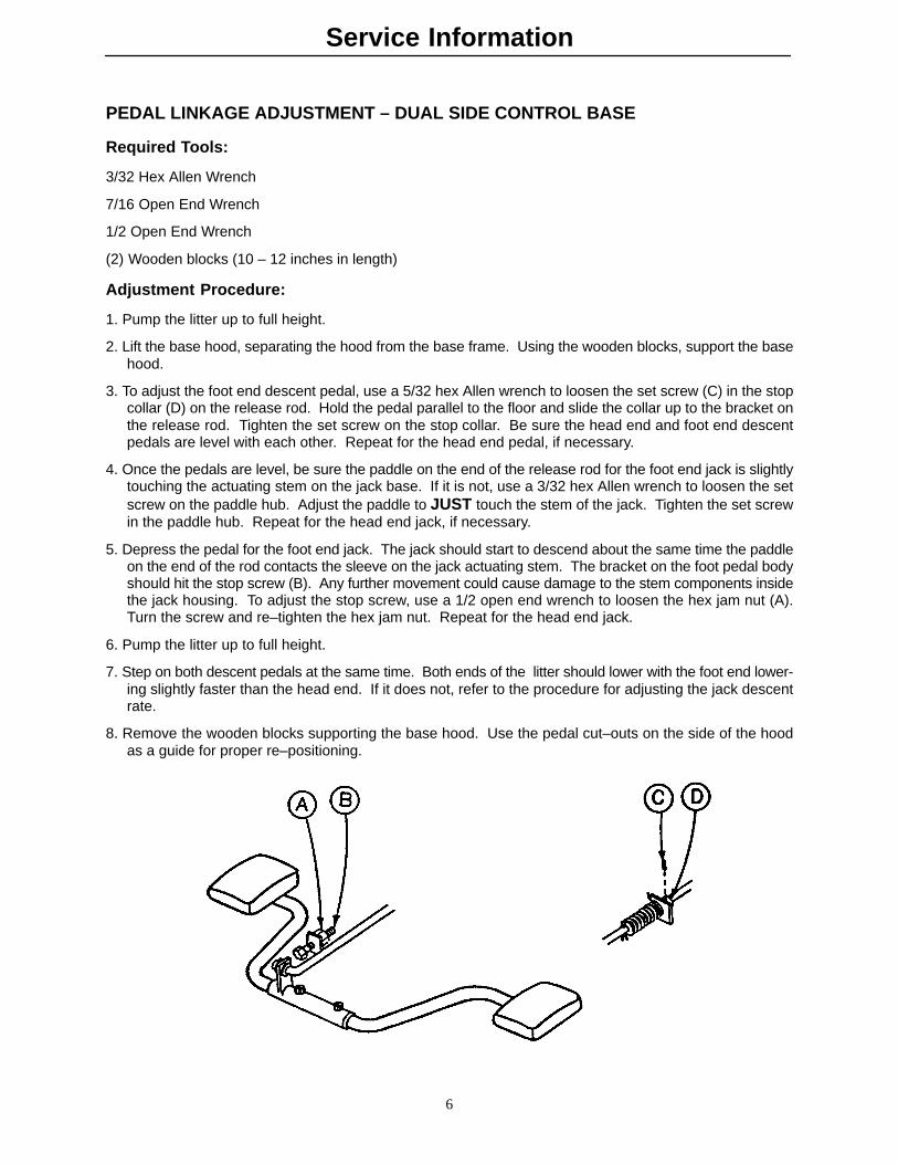
3. To adjust the foot end descent pedal, use a 5/32 hex Allen wrench to loosen the set screw (C) in the stopcollar (D) on the release rod. Hold the pedal parallel to the floor and slide the collar up to the bracket onthe release rod. Tighten the set screw on the stop collar. Be sure the head end and foot end descentpedals are level with each other. Repeat for the head end pedal, if necessary.
4. Once the pedals are level, be sure the paddle on the end of the release rod for the foot end jack is slightlytouching the actuating stem on the jack base. If it is not, use a 3/32 hex Allen wrench to loosen the setscrew on the paddle hub. Adjust the paddle to JUST touch the stem of the jack. Tighten the set screwin the paddle hub. Repeat for the head end jack, if necessary.
5. Depress the pedal for the foot end jack. The jack should start to descend about the same time the paddleon the end of the rod contacts the sleeve on the jack actuating stem. The bracket on the foot pedal bodyshould hit the stop screw (B). Any further movement could cause damage to the stem components insidethe jack housing. To adjust the stop screw, use a 1/2 open end wrench to loosen the hex jam nut (A).Turn the screw and re–tighten the hex jam nut. Repeat for the head end jack.
6. Pump the litter up to full height.
7. Step on both descent pedals at the same time. Both ends of the litter should lower with the foot end lower-ing slightly faster than the head end. If it does not, refer to the procedure for adjusting the jack descentrate.
8. Remove the wooden blocks supporting the base hood. Use the pedal cut–outs on the side of the hoodas a guide for proper re–positioning.
Service Information
7
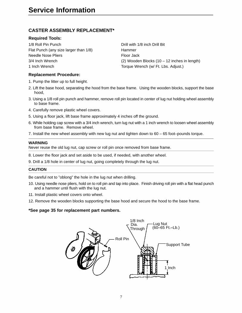
CASTER ASSEMBLY REPLACEMENT*
Required Tools:1/8 Roll Pin Punch Drill with 1/8 inch Drill BitFlat Punch (any size larger than 1/8) HammerNeedle Nose Pliers Floor Jack3/4 Inch Wrench (2) Wooden Blocks (10 – 12 inches in length)1 Inch Wrench Torque Wrench (w/ Ft. Lbs. Adjust.)
Replacement Procedure:
1. Pump the litter up to full height.
2. Lift the base hood, separating the hood from the base frame. Using the wooden blocks, support the basehood,
3. Using a 1/8 roll pin punch and hammer, remove roll pin located in center of lug nut holding wheel assemblyto base frame.
4. Carefully remove plastic wheel covers.
5. Using a floor jack, lift base frame approximately 4 inches off the ground.
6. While holding cap screw with a 3/4 inch wrench, turn lug nut with a 1 inch wrench to loosen wheel assemblyfrom base frame. Remove wheel.
7. Install the new wheel assembly with new lug nut and tighten down to 60 – 65 foot–pounds torque.
WARNINGNever reuse the old lug nut, cap screw or roll pin once removed from base frame.
8. Lower the floor jack and set aside to be used, if needed, with another wheel.
9. Drill a 1/8 hole in center of lug nut, going completely through the lug nut.
CAUTION
Be careful not to ”oblong” the hole in the lug nut when drilling.
10. Using needle nose pliers, hold on to roll pin and tap into place. Finish driving roll pin with a flat head punchand a hammer until flush with the lug nut.
11. Install plastic wheel covers onto wheel.
12. Remove the wooden blocks supporting the base hood and secure the hood to the base frame.
*See page 35 for replacement part numbers.
1/8 Inch
ThroughLug Nut(60–65 Ft.–Lb.)
Support Tube
1 Inch
Dia.
Roll Pin

Service Information
8
CASTER COVER INSTALLATION AND REMOVAL
Double Prongs
Single Prong
align cover with axle nut or bolt head, as shown.Push down on the opposite side of the cover untilsingle prong engages with caster horn.
Push with palm on cover until
Properly AttachedCover
To remove wheel cover, insert large screwdriver into cut–out inside of wheel cover and into the space between the double prongs.Pry up cover to disengage double prongs and push sharply upward
double prongs engage.
1.
2.
3.
Looking through the larger of the two side cut–outs,
Top View (Cut–Away)
Top View (Cut–Away)
Top View (Cut–Away)
to disengage single prong.
Service Information
9
HYDRAULIC SYSTEM TROUBLESHOOTING
NOTEBe sure the pedal linkage has been adjusted properly before beginning service on the jacks (see page 6).
PROBLEM/SYMPTOM SOLUTION
Jack will not raise to full height. Add hydraulic fluid (see p.10). Check for leaks.
Jack will not hold in raised position. Close the needle valve completely. If the jackholds, replace valve #1 (see p. 12). If the jackdoes not hold, replace valve #2 (see p. 13).
Jack will not pump up and the jack actuator roddoes not move.
Close the needle valve. If the jack will now pumpup, replace valve #1. If the jack still will not pumpup after closing the needle valve, replace valve #3(see p. 13).
Jack will not pump up but the jack actuator roddoes move when the pump pedal is activated.
Replace valve #2 (see p. 13).
Jack will not pump up and the jack actuator rodmay or may not move.
Remove excess air (vacuum) in system (see p.10).
Contact Stryker technical service at 1–800–327–0770 for further assistance.
ELECTRICAL TROUBLESHOOTING
PROBLEM/SYMPTOM SOLUTION
Power light not on after power cord is plugged in. Check wall receptacle for power.Remove control board cover & check for voltage(12 VDC) – test point 12 VDC ref. to gnd. If voltage is present, check power cord and re-place, if necessary.Check fuses F1, F2, F3, F4 on logic board.
Bed will not raise electrically. Check fuse F4 on logic control board. Replace, ifnecessary.Plug power cord in, depress pump pedal fully andlisten for switch activation. Check adjustment ofswitch inside the motor enclosure at the foot endof the stretcher. Replace switch (see page 19), ifnecessary. Check power cord and replace, if necessary.Replace capacitor (see page 20).Replace pump motor (see page 20).
No Gatch/Fowler function in either siderail. Check if lockout switch is on at either end of thestretcher. Be sure siderail controls are activated.Plug in power cord, press Gatch/Fowler switchand listen for switch activation – replace switch, ifnecessary.If only one siderail is not working, replace switchboard in that siderail (see page 26).Check fuses F2 (Gatch) and F3 (Fowler) on logiccontrol board.Check patient control switch cable and replace, ifnecessary.Replace Gatch and/or Fowler motors (see page21–23).
Service Information
10
CHECKING HYDRAULIC FLUID LEVEL
Required Tools:
3/8 Box End Wrench 3/4 Open End Wrench (2) Sawhorses (or equivalent)
Large Phillips Screwdriver Bungee Cords (or equivalent) Hydraulic Fluid (p/n )
Procedure:
WARNINGTo avoid personal injury or damage to the stretcher, remove the litter and the base hood before beginningservice on the jacks.
1. Raise the litter to the full up position.
2. Support both ends of the litter using sawhorses or the equivalent.
3. Using a 3/8 box end wrench, remove the square head set screws from both head and foot end jack supporttubes.
4. Press down on the release pedal for the end of the stretcher you are working on and, at the same time,push down on the jack actuator until it is fully down.
5. Using a large Phillips screwdriver, remove the four screws securing the base hood. Using bungee cordsor the equivalent, lift and support the base hood high enough to access the fill plug on the side of the jack.
6. Be sure there are no hydraulic leaks. If there are, jack replacement will be necessary.
7. Using a 3/4 open end wrench, slowly turn the fill plug counterclockwise to allow excess system pressureto vent. Remove the fill plug.
8. The hydraulic fluid should be visible at the bottom of the fill hole. If it is not, add Mobil AW–32 hydraulicfluid (Stryker part number 1550–570–10) until the fluid is visible at the bottom of the fill hole. Replace thefill plug.
CAUTION
Use of other types of oil may damage hydraulic units.
9. Replace the hood and reattach the litter.
REMOVAL OF EXCESS AIR (VACUUM) FROM THE HYDRAULIC SYSTEM
Procedure:
1. Verify all hydraulic linkages are secure and operating properly (see pedal linkage adjustment procedurepage 6).
2. Hold down the descent pedals and the pump pedal and allow the system to circulate for approximately 10seconds. This will force the air through the system and the jack should now pump up.
Service Information
11
JACK DESCENT RATE ADJUSTMENT
Required Tools:
Standard Screwdriver Large Phillips Screwdriver (2) 10 – 12 Inch Wooden Blocks
Adjustment Procedure:
1. Pump the litter up to full height.
2. Using a large Phillips screwdriver, remove the four Phillips screws securing the base hood. Lift the basehood and support it using the wooden blocks.
3. The descent rate needle valve is located on the base of the jack. Turning the needle valve clockwise, witha screwdriver, will decrease the rate of descent. Turning it counterclockwise will increase the rate of de-scent.
4. Adjust the needle valve so that the foot end of the stretcher descends slightly faster than the head end.
NOTEThe larger percentage of a patient’s weight is located in the torso area. Adjust descent rate accordingly.
5. Check all wires and cables to assure none were pulled loose.
6. Remove the wooden blocks supporting the base hood and replace the screws securing the hood to thebase frame.
NOTEThe jack descent rate was preset at the factory to drop the foot end faster than the head. It is recommendedthat the foot drop faster to avoid patient disorientation.

Service Information
12
HYDRAULIC CHECK VALVE REPLACEMENT – NON ELECTRIC LIFT BASE
Required Tools:3/8 Box End Wrench Stiff Wire (with bent, pointed end) Small Needle Nose Pliers3/4 Open End Wrench Torque Wrench (with Ft. Lbs. adjust.)7/32 Hex Allen Wrench 1/2 Inch Diameter Rod
Replacement of Valve #1
WARNINGTo avoid personal injury or damage to the stretcher, remove the litter and the base hood before beginningservice on the stretcher.
1. Using a 3/8 box end wrench, remove square head set screws from both head and foot end jack supporttubes. Remove litter top and set aside.
2. Lift base hood off base frame and set aside.3. Lower the jack to full down position. The actuator must be manually lowered while depressing the appropri-
ate release pedal.4. Remove the pin body assembly (4) with a 3/4 open end wrench and discard the housing gasket (5).NOTEAlthough the hydraulic fluid is not under pressure, some fluid loss will occur. The fluid loss should be minimalbut covering the floor is advisable.5. Using a 7/32 hex Allen wrench, remove the valve plug (6).6. Using a stiff wire with a bent, pointed end, remove and discard the valve (1) and the seal (7).7. Install the new seal (7) flat to the bottom of its hole with a 1/2 inch diameter rod and install the new valve
(1) with the beveled end out (as shown in the illustration).
8. Install the valve plug (6) with the countersunk end first and the beveled end out. Tighten to 10 foot poundstorque.
9. Install the pin body assembly (4) with the new housing gasket (5) and tighten to 10 foot pounds torque.10. Pump up the jack to the maximum height. Apply weight to be sure the jack holds its position and there
are no hydraulic leaks before replacing the base hood and the litter.
ITEM PART NO. PART NAME 1 926–20–153 Check Valve 2 926–20–153 Check Valve 3 715–1–341 Poppet 4 715–100–312 Pin Housing Assembly 5 715–1–330 Housing Gasket 6 715–1–309 Valve Plug 7 926–20–154 Seal 8 715–1–101 Base Plug 9 926–20–156 Seal 10 715–1–309 Valve Plug 11 926–20–154 Seal 12 715–1–301 Base Plug 13 926–20–156 Seal 14 390–2–134 Conical Comp. Spring
FILLER PLUG
3
14
12
13DESCENT RATENEEDLE VALVE

Service Information
13
HYDRAULIC CHECK VALVE REPLACEMENT – NON ELECTRIC LIFT BASE (CON-TINUED)
Replacement of Valve #2
WARNINGTo avoid personal injury or damage to the stretcher, remove the litter and the base hood before beginningservice on the jacks. Lower the jack rod completely to relieve the pressure on the pump piston side of thejack. This will prevent large hydraulic fluid loss and possible damage when the base plugs are removed.
1. Remove the base plug (8) and discard the seal (9).
2. Remove the valve plug (10).
3. Using a stiff wire with a bent, pointed end, remove the valve (2) and the seal (11) and discard the seal.
4. Install the new seal (11) flat to the bottom of its hole with a 1/2” diameter rod.
5. Install the new valve (2) with the beveled end out (as shown in the illustration).
6. Install the valve plug (10) and tighten to 10 foot–pounds torque.
7. Install the new seal (9) with the base plug (8) and tighten to 10 foot–pounds torque.
8. Pump up the jack to the maximum height.
9. Be sure there are no hydraulic leaks before replacing the base hood and the litter.
Replacement of Valve (Poppet) #3
WARNINGTo avoid personal injury or damage to the stretcher, remove the litter and the base hood before beginningservice on the jacks. Lower the jack rod completely to relieve the pressure on the pump piston side of thejack. This will prevent large hydraulic fluid loss and possible damage when the base plugs are removed.
1. Remove the base plug (12) and discard the seal (13).
2. Remove the compression spring (14).
3. Using a small needle nose pliers, remove the poppet (3).
4. Install the new poppet (3).
5. Install the compression spring (14).
6. Install the new seal (13) and the base plug (12) and tighten to 10 foot–pounds torque.
7. Pump up the jack to the maximum height to check its operation.
8. Check for hydraulic leaks before replacing the base hood and the litter.
Service Information
14
HYDRAULIC PRESSURE HOSE REPLACEMENT
Required Tools:
Large Phillips Screwdriver 9/16” Open End Wrench 11/16” Open End Wrench
6” 3/8 Drive Extension 3/8” Drive Ratchet Paper Towels or RagsString or Bungee Cord Modified Flair Nut Wrench – p/n 1550–570–5
Procedure:
1. Raise the litter to the full up position. Unplug the stretcher power cord from the wall socket.
NOTEIf the hydraulic system is completely disabled, manually lift up on the litter to raise the jack actuator.
2. Remove the four Phillips head screws securing the base hood to the base frame. Lift the hood and secureit to the litter using string or bungee cords. Use caution when lifting the hood so none of the wires leadingto the litter are pulled loose.
3. Locate the black pressure hose leading from the top of the jack casting to the head of the pump. Usinga 9/16” open end wrench, remove the hose from the 90� fitting. Before removing the hose from the jackbase, pack a paper towel or rag around the fitting to soak up the hydraulic oil that will run out of the hose.Using a modified flair nut wrench, loosen the hose fitting and remove the hose.
4. To install the new hose, pass it behind the jack brace and thread it onto the jack base fitting.
CAUTION
Do not over–tighten the fitting. Thread the brass nut by hand and tighten approximately 60� or one flat ofthe nut.
5. Attach the other end of the hose to the pump and tighten as described above. If the hose is tight or stressed,it may be necessary to change the angle of the fitting on the pump. Using an 11/16” open end wrench,loosen the nut against the pump 1/2 turn, reposition the fitting and tighten the nut. Remove the paper towelor rag used to soak up the hydraulic oil.
6. To replace the hydraulic oil lost when the hose was removed, remove the jack filler plug and add approxi-mately 1 ounce of Mobil AW–32 hydraulic oil (Stryker part number ). Do not fill to the bottom of the fill holebecause most of the oil is in the actuator cylinder when the litter is raised.
7. After the new hydraulic hose or hoses have been installed, plug the stretcher power cord into a properlygrounded wall receptacle. Cycle the litter up and down approximately 10 times and inspect the hose(s)and fittings for leaks.
8. Before installing the base hood, inspect all wires and connectors and be sure none have pulled loose. Posi-tion the hood and assure no wires are hanging out or pinched. Replace the four screws to hold the hoodin place.

Service Information
15
BRAKE ADJUSTMENT
Required Tools:
3/32” Hex Allen WrenchPry BarThread ”Locktite”
BASE LUBRICATION POINTS
1. Lubricate brake adjuster rodaround area shown with MPG–2grease or equivalent.
Do not grease area shown.
Service Information
16
BRAKE CAM REPLACEMENT
Brake Cam Part Number 715–1–213
Required Tools:
Phillips Screwdriver String or Bungee Cord 3/32” Allen Wrench1/8” Allen Wrench
Procedure:
1. Unplug the power cord from the wall socket.
2. Remove the four Phillips screws holding the base hood to the frame. Lift and support the base hood usingstring or bungee cord.
3. Using a 3/32” Allen wrench, loosen the set screw holding the brake adjuster to the brake ring and turn theadjuster clockwise to remove it.
4. Using a 1/8” Allen wrench, remove the shoulder bolt and nut holding the brake link on the cam and removethe cam.
5. Reverse steps 3 and 4 to install the new cam. Apply and release the brakes to assure they operate properly.If adjustment is required, see page 15. Reinstall the base hood.
BRAKE RING REPLACEMENT
Brake Ring Part Number 715–1–61
Required Tools:
Phillips Screwdriver String or Bungee Cord Floor Jack, Small Crate (or equiv.)Large Standard Screwdriver 3/32” Allen Wrench 11/16” Socket & Ratchet5/8” Wrench Needle–Nose Pliers (2) 7/16” Wrenches
Procedure:
1. Unplug the power cord from the wall socket.
2. Remove the four Phillips screws holding the base hood to the frame. Lift and support the base hood usingstring or bungee cord. Put the brake/steer pedal in the neutral position. Lift the end of the base needingservice until the casters are approximately 12” off the floor and support it with a jack or the equivalent.
3. Using a 3/32” Allen wrench, loosen the set screw holding the brake adjuster to the brake ring and turn theadjuster clockwise to remove it.
4. Remove the wheel covers on both casters (see page 8).
5. Remove one of the caster assemblies (see page 7). On the other caster, use an 11/16” socket and ratchetand a 5/8” wrench to remove the nut and bolt holding the wheel on the caster horn and remove only thewheel.
6. Using two 7/16” wrenches, remove the power cord bracket from the base.

Service Information
17
BRAKE RING REPLACEMENT (CONTINUED)
7. Using needle–nose pliers, carefully squeeze and remove the spring between the brake cam and the brakering.
WARNINGThe spring is tightly compressed. Use caution when removing it or personal injury could result.
8. If you are working on an end control base, remove the spring from the pump pedal.
9. Lower the brake ring and remove it from the base. Remove the brake pads and bushings and install themon the new brake ring.
10. Reverse the above steps to install the new brake ring and reinstall the caster and wheel. Apply and releasethe brakes to assure they operate properly. If adjustment is required, see page 15. Reinstall the base hood.
POWER CORD REPLACEMENT
Power Cord Part Number 1550–85–10
Required Tools:
Large Phillips Screwdriver String or Bungee Cord Wire CuttersPliers 5/32” Allen Wrench 3/8” Wrench
Procedure:
1. Unplug the power cord from the wall socket. Press fully down on the brake pedal to set the brakes. Pumpthe lift pedal and raise the litter fully. Remove the four Phillips screws holding the base hood to the baseframe. Lift and support the base hood using string or bungee cord. Properly ground yourself (see page18).
2. Disconnect the black and white wires from the motor cable inside the motor enclosure and clip off the con-nectors. Using a 5/32” Allen wrench and a 3/8” wrench, remove the nut and screw holding the greenground wire to the base tube.
3. Using pliers, squeeze and pull the cord strain relief out of the motor enclosure and pull the cord throughthe hole in the enclosure. Remove and save the strain relief. Using a 15/16” wrench, remove the plasticnut on the connector side of the cord and pull the cord out through the mounting bracket.
4. Remove the plastic nut from the connector side of the new power cord. Thread the new power cord throughthe bracket and replace and tighten the plastic nut. Clamp on the strain relief and push it back into theenclosure.
5. Connect the black and white wires to the motor cable. Reattach the green ground wire.
6. Reattach the base hood using the four Phillips screws. Plug the power cord into a properly grounded wallreceptacle and be sure the stretcher has power before returning it to service.

Service Information
18
STATIC DISCHARGE PRECAUTIONS
The electronic circuits in the 1550 are completely protected from static electricity damage only while thestretcher is assembled. It is extremely important that all service personnel always use adequate static protec-tion when servicing the electronic systems of the 1550. Whenever you are touching wires, you should beusing static protection.
Static Protection Equipment
The necessary equipment for proper static protection is:
� 1 static wrist strap; 3M part number 2214 or equivalent,
� 1 grounding plug; 3M part number 61038 or equivalent,
� 1 test lead with a banana plug on one end and an alligator clip on the other; Smith part number N132B699 or equivalent.
CAUTION
All electronic service parts will be shipped in static shielding bags. Do not open the bags until you have com-pleted steps 2 and 3 of the following procedure. Do not place unprotected circuit boards on the floor. All circuitboards to be returned to Stryker Medical should be shipped in the static shielding bags the new boards wereshipped in.
Static Protection Procedure
1. Turn off the main power switch at the foot end of the stretcher and unplug the power cord from the wallreceptacle.
2. Insert the grounding plug into a properly grounded hospital grade wall receptacle. Plug the banana plugof the test lead into the receptacle on the grounding plug. Connect the alligator clip on the other end ofthe test lead to the ground chain of the stretcher.
3. Place the static control wrist strap on your wrist. Connect the alligator clip at the other end of the wrist strapcord to the ground chain of the stretcher.
STRETCHER
GROUNDING DIAGRAM
Service Information
19
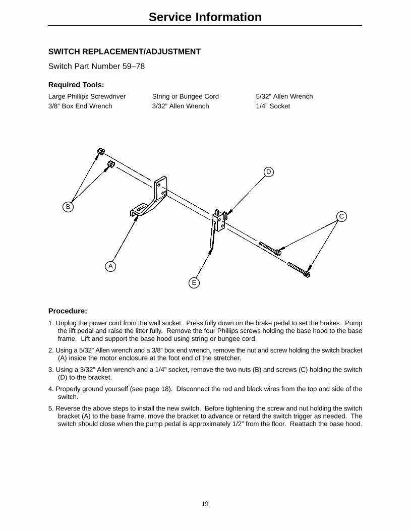
SWITCH REPLACEMENT/ADJUSTMENT
Switch Part Number 59–78
Required Tools:
Large Phillips Screwdriver String or Bungee Cord 5/32” Allen Wrench3/8” Box End Wrench 3/32” Allen Wrench 1/4” Socket
A
BC
D
E
Procedure:
1. Unplug the power cord from the wall socket. Press fully down on the brake pedal to set the brakes. Pumpthe lift pedal and raise the litter fully. Remove the four Phillips screws holding the base hood to the baseframe. Lift and support the base hood using string or bungee cord.
2. Using a 5/32” Allen wrench and a 3/8” box end wrench, remove the nut and screw holding the switch bracket(A) inside the motor enclosure at the foot end of the stretcher.
3. Using a 3/32” Allen wrench and a 1/4” socket, remove the two nuts (B) and screws (C) holding the switch(D) to the bracket.
4. Properly ground yourself (see page 18). DIsconnect the red and black wires from the top and side of theswitch.
5. Reverse the above steps to install the new switch. Before tightening the screw and nut holding the switchbracket (A) to the base frame, move the bracket to advance or retard the switch trigger as needed. Theswitch should close when the pump pedal is approximately 1/2” from the floor. Reattach the base hood.

Service Information
20
JACK/MOTOR REPLACEMENT
Head (Control) End Jack/Motor Assembly Part Number 1550–70–30, Foot End Jack/Motor Assembly Part Number 1550–70–35, Jack Part Number 1550–70–25, Motor Part Number 1550–70–10, Capacitor Part Number 1550–70–9
Required Tools:Large Phillips Screwdriver String or Bungee Cord Sawhorses (or equivalent)5/16” Open End Wrench 1/2” Socket w/6” Extension 1/2” Box End Wrench5/32” Allen Wrench 3/8” Box End Wrench 1/4” Allen WrenchSmall Standard Screwdriver 7/16” Box End Wrench
Procedure:
1. Unplug the power cord from the wall socket. Press fully down on the brake pedal to set the brakes. Pumpthe lift pedal and fully raise the litter. Remove the four Phillips screws holding the base hood to the frame.Lift and support the base hood using string or bungee cord. Using sawhorses or the equivalent, supportthe litter at the end of the stretcher that needs service.
2. Using a 3/8” box end wrench, remove the screw holding the jack to the litter support tube.
3. Press down on the release pedal for the end of the stretcher you are working on and, at the same time,push down on the jack actuator until it is fully down.
4. Put the brake/steer pedal in neutral and move the end of the base you are working on out from under thelitter to allow better access to the jack and motor. Press fully down on the pedal to reset the brakes.
WARNINGMove only the base. Be very careful not to move the litter. Personal injury could result if the litter falls offthe sawhorses (or equivalent) supporting it.
5. Using a 1/2” socket and a 1/2” wrench, remove the nuts and bolts holding the jack support bracket on bothsides of the jack. Using a 1/2” socket, remove the two nuts and bolts holding the support bracket on thebase tube bracket.
6. Properly ground yourself (see page 18). Disconnect the motor cables.
7. Using a 1/2” ratchet with a 6” extension and a 1/2” wrench, remove the five nuts and bolts holding the jack,motor and enclosure on the base frame,
8. Using a 5/32” Allen wrench and a 3/8” box end wrench, remove the nut and screw holding the switch bracketinside the motor enclosure.
9. Using a 1/4” Allen wrench and a 1/2” box end wrench, remove the nut and bolt holding the jack pump pistonto the linkage. If you are replacing the head (control) end jack, remove the nut and compress the jackspring before removing the bolt. Carefully release the spring and remove it from the spring holder.
10. Pull out the jack and motor. Using a 7/16” wrench, loosen the four fiberlock nuts under the bottom mountingbracket and slide the motor out of the two ”U” brackets.
11. If the capacitor needs to be replaced, use a small, standard screwdriver to remove it from the bracket onthe bottom of the enclosure.
12. Place the new jack/motor assembly in the enclosure. Reinstall the jack support brackets. Reinstall the jackpump piston to the linkage.
13. Line up the enclosure and motor with the holes in the base frame and reinstall the five nuts and bolts.
14. If the capacitor is being replaced, push the new capacitor into the bracket inside the enclosure. Reinstallthe switch (see page 19 for adjustment instructions). Reconnect all wires and cables.
15. Pump the lift pedal to raise the jack actuator and reattach the jack to the litter support tube. Reattach thebase hood. Test the bed lift functions before returning the stretcher to service.
Service Information
21
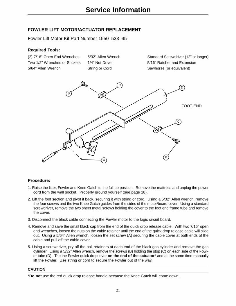
FOWLER LIFT MOTOR/ACTUATOR REPLACEMENT
Fowler Lift Motor Kit Part Number 1550–533–45
Required Tools:
(2) 7/16” Open End Wrenches 5/32” Allen Wrench Standard Screwdriver (12” or longer)
Two 1/2” Wrenches or Sockets 1/4” Nut Driver 5/16” Ratchet and Extension
5/64” Allen Wrench String or Cord Sawhorse (or equivalent)
A
C
C
B
B
D
FOOT END
Procedure:
1. Raise the litter, Fowler and Knee Gatch to the full up position. Remove the mattress and unplug the powercord from the wall socket. Properly ground yourself (see page 18).
2. Lift the foot section and pivot it back, securing it with string or cord. Using a 5/32” Allen wrench, removethe four screws and the two Knee Gatch guides from the sides of the motor/board cover. Using a standardscrewdriver, remove the two sheet metal screws holding the cover to the foot end frame tube and removethe cover.
3. Disconnect the black cable connecting the Fowler motor to the logic circuit board.
4. Remove and save the small black cap from the end of the quick drop release cable. With two 7/16” openend wrenches, loosen the nuts on the cable retainer until the end of the quick drop release cable will slideout. Using a 5/64” Allen wrench, loosen the set screw (A) securing the cable cover at both ends of thecable and pull off the cable cover.
5. Using a screwdriver, pry off the ball retainers at each end of the black gas cylinder and remove the gascylinder. Using a 5/32” Allen wrench, remove the screws (B) holding the stop (C) on each side of the Fowl-er tube (D). Trip the Fowler quick drop lever on the end of the actuator* and at the same time manuallylift the Fowler. Use string or cord to secure the Fowler out of the way.
CAUTION
*Do not use the red quick drop release handle because the Knee Gatch will come down.
Service Information
22
FOWLER LIFT MOTOR/ACTUATOR REPLACEMENT (CONTINUED)
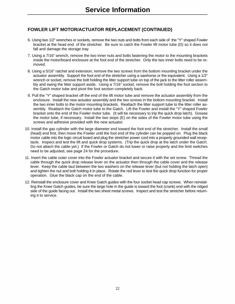
6. Using two 1/2” wrenches or sockets, remove the two nuts and bolts from each side of the ”Y” shaped Fowlerbracket at the head end of the stretcher. Be sure to catch the Fowler lift motor tube (D) so it does notfall and damage the storage tray.
7. Using a 7/16” wrench, remove the two inner nuts and bolts fastening the motor to the mounting bracketsinside the motor/board enclosure at the foot end of the stretcher. Only the two inner bolts need to be re-moved.
8. Using a 5/16” ratchet and extension, remove the two screws from the bottom mounting bracket under theactuator assembly. Support the foot end of the stretcher using a sawhorse or the equivalent. Using a 1/2”wrench or socket, remove the bolt holding the litter support tube on top of the jack to the litter roller assem-bly and swing the litter support aside. Using a 7/16” socket, remove the bolt holding the foot section tothe Gatch motor tube and pivot the foot section completely back.
9. Pull the ”Y” shaped bracket off the end of the lift motor tube and remove the actuator assembly from theenclosure. Install the new actuator assembly and the two screws in the bottom mounting bracket. Installthe two inner bolts to the motor mounting brackets. Reattach the litter support tube to the litter roller as-sembly. Reattach the Gatch motor tube to the Gatch. Lift the Fowler and install the ”Y” shaped Fowlerbracket onto the end of the Fowler motor tube. (It will be necessary to trip the quick drop latch). Greasethe motor tube, if necessary. Install the two stops (E) on the sides of the Fowler motor tube using thescrews and adhesive provided with the new actuator.
10. Install the gas cylinder with the large diameter end toward the foot end of the stretcher. Install the small(head) end first, then move the Fowler until the foot end of the cylinder can be popped on. Plug the blackmotor cable into the logic circuit board and plug the stretcher power cord into a properly grounded wall recep-tacle. Inspect and test the lift and quick drop systems. (Trip the quick drop at the latch under the Gatch.Do not attach the cable yet.) If the Fowler or Gatch do not lower or raise properly and the limit switchesneed to be adjusted, see page 24 for the procedure.
11. Insert the cable outer cover into the Fowler actuator bracket and secure it with the set screw. Thread thecable through the quick drop release lever on the actuator then through the cable cover and the releaselever. Keep the cable taut between the two washers on the release lever (but not holding the latch open)and tighten the nut and bolt holding it in place. Rotate the red lever to test the quick drop function for properoperation. Glue the black cap on the end of the cable.
12. Reinstall the enclosure cover and Knee Gatch guides with the four socket head cap screws. When reinstal-ling the Knee Gatch guides, be sure the large hole in the guide is toward the foot (crank) end with the ridgedside of the guide facing out. Install the two sheet metal screws. Inspect and test the stretcher before return-ing it to service.
Service Information
23
GATCH LIFT MOTOR/ACTUATOR REPLACEMENT
Required Tools:
7/16” Socket Ratchet 1/4” Socket or Wrench
Inclinometer 5/16” Socket 5/64” Allen Wrench3” Extension Medium Standard Screwdriver 1/2” Wrench or Socket1/2” Socket 5/32” Wrench (2) 7/16” WrenchesString or Cord Sawhorse (or equivalent)
Procedure:
1. Unplug the power cord from the wall socket. Properly ground yourself (see page 18).
2. Using a 1/2” wrench and socket, disconnect the bolts holding the Gatch motor assembly to the Knee Gatchmounting bracket underneath the litter midsection.
3. Lift the foot section and pivot it back, securing it with a string or cord. Using a 5/32” Allen wrench, removethe four screws and two Knee Gatch guides from the sides of the motor/board enclosure cover. Using astandard screwdriver, remove the two sheet metal screws holding the cover to the foot end frame tubeand remove the cover.
4. Manually crank up the Fowler (head end) to expose the quick drop lever assembly. Remove and save thesmall black cap from the end of the quick drop release cable. With two 7/16” open end wrenches, loosenthe nut on the cable retainer until the quick drop release cable will slide out. Using a 5/64” Allen wrench,loosen the set screw securing the cable cover at both ends of the cable and pull off the cable cover.
5. Using a 7/16” wrench, remove the two inner nuts and bolts fastening the Gatch motor to the mounting brack-ets inside the motor enclosure. Only the two inner bolts need to be removed.
6. Using a 5/16” socket and extension, remove the two bolts from the bottom mounting bracket under theactuator assembly inside the motor enclosure.
7. Unplug the black Gatch motor cable from the logic circuit board.
8. Support the foot end of the stretcher using a sawhorse or the equivalent. Using a 1/2” wrench or socket,remove the bolt holding the litter support tube on top of the jack to the litter roller assembly and swing thelitter support aside. Using a 7/16” socket, remove the bolt holding the foot section to the Gatch motor tubeand pivot the foot section completely back.
9. Remove Gatch motor.
10. Reverse steps 2–8 to install new Gatch motor.
11. Plug the stretcher power cord into a properly grounded wall socket and use siderail control to raise the Gatchuntil the motor stops.
12. Using an inclinometer, assure the Gatch is at a 30� angle. If it is not, run the motor until a 30� angle isachieved, then disconnect the motor from the Gatch mounting bracket and quick drop release cable.
13. Using the siderail controls, run the motor up, allowing the motor to spin freely, until it stops.
14. Reattach the motor to the Gatch mounting bracket and quick drop release cable and assure the Gatch isnow at a 30� angle. Run the Gatch fully down and assure it reaches the full down position. If the motorstops before the Gatch is fully down or continues to run after the Gatch is resting on the rubber Gatch stops,see page 24 for limit switch adjustment.

Service Information
24
FOWLER AND KNEE GATCH MOTOR/ACTUATOR ADJUSTMENT
Procedure:
1. Electrically raise the Fowler and/or Knee Gatch until it stops. Use an inclinometer to check the angle ofthe Fowler/Knee Gatch. If the angle is not 70�– 80� for the Fowler and 28�– 30� for the Gatch, the actua-tor(s) will need to be adjusted.
2. Lower the Fowler down flat and remove the socket head cap screws and spacers holding the drive bar tothe crankscrew/actuator assembly.
3. Standing at the head end of the bed, turn the outer drive tube clockwise if the Fowler angle is less than70�. Turn the outer drive tube counterclockwise if the Fowler angle is more than 80�. Reattach the drivebar to the crankscrew/actuator assembly. Electrically raise the Fowler fully and check the angle.
4. If the Knee Gatch angle is not correct, disconnect the pivot bolt from the Gatch. Standing at the head endof the bed, turn the drive tube clockwise if the Gatch angle is less than 28�. Turn the drive tube counter-clockwise if the Gatch angle is more than 30�. Reattach the drive bar to the crankscrew/actuator assem-bly. Electrically raise the Gatch fully and check the angle.
NOTEOne turn of the drive tube is equal to approximately 2� of Fowler/Gatch angle.
5. After the Fowler and Gatch upper limits are set properly, rotate the quick drop release lever to lower theFowler and Gatch. Press and hold the Fowler and Gatch down buttons until the motor stops to reset thequick drop Fowler and Gatch. The Fowler and Gatch should stop on the rests. So there isn’t any tensionon the actuators, you should be able to pull up slightly on the Fowler and Knee Gatch. See the procedurebelow for limit switch adjustment if the Gatch limits are not properly set.
FOWLER AND KNEE GATCH LIMIT SWITCH ADJUSTMENT
Procedure:
1. If the motor does not stop when the Fowler or Gatch reaches the full down position or stops before theFowler or Gatch is fully down on the rests, the limit switch needs to be adjusted.
2. Lower the Fowler and/or Gatch to the full down position being careful not to exceed the downward limiton the rubber stops.
3. Raise the Fowler/Gatch approximately 1”. Rotate the quick drop release lever and run the Fowler/Gatchmotor down to reset the quick drop.
4. Lift the foot section and pivot it back, securing it with a string or cord. Using a 5/32” Allen wrench, removethe four screws and two Knee Gatch guides from the sides of the motor/board enclosure cover. Using astandard screwdriver, remove the two sheet metal screws holding the cover to the foot end frame tubeand remove the cover.
5. Using a 1/4” wrench, remove the two screws on the end of the actuator holding the round limit switch coverplate and remove the plate to expose the limit switches.
6. Loosen the two screws on the outer limit switch cam and turn the cam by hand until it just contacts thelimit switch. The switch will click when the cam contacts it.
7. Tighten the screws on the cam.
8. Raise the Fowler/Gatch fully then rotate the quick drop lever and hold down the lowering button on thesiderail to reset the quick drop. The Fowler/Gatch should lower fully down on the rests and the motorshould stop. If it doesn’t, repeat steps 6–8.
9. Reattach the switch cover plate and motor enclosure cover when the switch is set properly.

Service Information
25
LOGIC CIRCUIT BOARD REPLACEMENT
Logic Circuit Board Part Number 1550–80–900
Required Tools:
Standard Screwdriver 5/32” Allen Wrench 7/64” Allen Wrench
Procedure:
1. Unplug the power cord from the wall socket. Properly ground yourself (see page 18).
2. Lift the foot section and pivot it back, securing it with a string or cord. Using a 5/32” Allen wrench, removethe four screws and two Knee Gatch guides from the sides of the motor/board enclosure cover. Using astandard screwdriver, remove the two sheet metal screws holding the cover to the foot end frame tubeand remove the cover.
3. Disconnect all cables and connectors from the logic circuit board, noting their locations so they will be re-connected properly.
4. Using a 7/64” Allen wrench, remove the 6 Allen screws on the bottom of the motor/board enclosure. Liftthe logic circuit board out of the enclosure.
5. Reverse the above steps to install the new circuit board. Reinstall the enclosure cover and Knee Gatchguides with the four socket head cap screws. When reinstalling the Knee Gatch guides, be sure the largehole in the guide is toward the foot (crank) end with the ridged side of the guide facing out. Install the twosheet metal screws. Test all bed functions before returning the stretcher to service.
PATIENT CONTROL LOCKOUT SWITCH REPLACEMENT
Rocker Switch Part Number 59–68
Required Tools:
Standard Screwdriver 5/32” Allen Wrench
Procedure:
1. Unplug the power cord from the wall socket. Properly ground yourself (see page 18).
2. Lift the foot section and pivot it back, securing it with a string or cord. Using a 5/32” Allen wrench, removethe four screws and two Knee Gatch guides from the sides of the motor/board enclosure cover. Using astandard screwdriver, remove the two sheet metal screws holding the cover to the foot end frame tubeand remove the cover.
3. Disconnect the three cables leading from the rocker switch to the lockout cable on the logic circuit board.
4. From inside the enclosure, squeeze the sides of the rocker switch and push the switch out of the frametube.
5. Push the new switch into the frame tube, threading the three cables through the tube. Connect the cablesto the lockout cable, being sure the white cable is connected in the center.
6. Reinstall the enclosure cover and Knee Gatch guides with the four socket head cap screws. When reinstal-ling the Knee Gatch guides, be sure the large hole in the guide is toward the foot (crank) end with the ridgedside of the guide facing out. Install the two sheet metal screws.
7. Plug the stretcher power cord into a properly grounded wall receptacle and test the lockout function beforereturning the stretcher to service.

Service Information
26
PATIENT CONTROL LOCKOUT LED REPLACEMENT
Required Tools:
Standard Screwdriver 5/32” Allen Wrench Wire Cutters
Procedure:
1. Unplug the power cord from the wall socket. Properly ground yourself (see page 18).
2. Lift the foot section and pivot it back, securing it with a string or cord. Using a 5/32” Allen wrench, removethe four screws and two Knee Gatch guides from the sides of the motor/board enclosure cover. Using astandard screwdriver, remove the two sheet metal screws holding the cover to the foot end frame tubeand remove the cover.
3. Disconnect the red and black LED wires from the lockout cable. Clip the red and black wires and pushthe LED out of the litter frame tube.
4. Thread the new LED wires through the frame tube. Push the new LED into the frame tube. Crimp newconnectors on the red and black wires on the new LED. Connect the new LED to the lockout cable onthe logic circuit board.
5. Reinstall the enclosure cover and Knee Gatch guides with the four socket head cap screws. When reinstal-ling the Knee Gatch guides, be sure the large hole in the guide is toward the foot (crank) end with the ridgedside of the guide facing out. Install the two sheet metal screws.
6. Plug the stretcher power cord into a properly grounded wall receptacle and be sure the LED lights whenthe lockout function is activated before returning the stretcher to service.
SIDERAIL PATIENT CONTROL REPLACEMENT
Required Tools:
5/64” Allen Wrench
Procedure:
1. Unplug the power cord from the wall socket. Properly ground yourself (see page 18). Lower the siderail.
2. Peel the label off the siderail top rail.
3. Using a 5/64” Allen wrench, remove the two screws from the top rail.
4. Pull the control assembly out of the inside of the top rail and disconnect the cable from the switch boardinside the rail.
5. Reverse the above steps to install the new control assembly, being sure the cable is aligned with the groovein the switch housing and doesn’t get pinched.
6. Plug the stretcher power cord into a properly grounded wall receptacle and be sure the siderail control isworking properly before returning the stretcher to service.
Field Replacement Parts
27
REPLACEMENT PARTS
ITEM PART NUMBER
Brake Cam 715–1–221. . . . . . . . . . . . . . . . . . . . . . . . . . . . . . . . . . . . . . . . . . . . . . . . . . . . . . . . . . Brake Ring 715–1–61. . . . . . . . . . . . . . . . . . . . . . . . . . . . . . . . . . . . . . . . . . . . . . . . . . . . . . . . . . Power Cord 1550–85–10. . . . . . . . . . . . . . . . . . . . . . . . . . . . . . . . . . . . . . . . . . . . . . . . . . . . . . . . . Switch 59–78. . . . . . . . . . . . . . . . . . . . . . . . . . . . . . . . . . . . . . . . . . . . . . . . . . . . . . . . . . . . . . Hydraulic Jack 1550–70–25. . . . . . . . . . . . . . . . . . . . . . . . . . . . . . . . . . . . . . . . . . . . . . . . . . . . . . . Capacitor 1550–70–9. . . . . . . . . . . . . . . . . . . . . . . . . . . . . . . . . . . . . . . . . . . . . . . . . . . . . . . . . . . Logic Circuit Board 1550–80–900. . . . . . . . . . . . . . . . . . . . . . . . . . . . . . . . . . . . . . . . . . . . . . . . . . . Rocker Switch 59–68. . . . . . . . . . . . . . . . . . . . . . . . . . . . . . . . . . . . . . . . . . . . . . . . . . . . . . . Brake Adjuster 715–1–150. . . . . . . . . . . . . . . . . . . . . . . . . . . . . . . . . . . . . . . . . . . . . . . . . . . . . . . Rubber Pedal (Release) 721–40–25. . . . . . . . . . . . . . . . . . . . . . . . . . . . . . . . . . . . . . . . . . . . . . Side Control Pedal Pad 715–1–126. . . . . . . . . . . . . . . . . . . . . . . . . . . . . . . . . . . . . . . . . . . . . . . Hydraulic Oil Kit 1550–570–10. . . . . . . . . . . . . . . . . . . . . . . . . . . . . . . . . . . . . . . . . . . . . . . . . . . . . .

1550–1–1 Base/H
oo
d A
ssemb
ly (With
ou
t Lift O
ptio
n)
28
p/n 715–1–260Jacks w/ Foot Controls
p/n 3–62 (Ref.)
p/n 11–262 (Ref.)
p/n 16–36 (Ref.)
TO UMBILICALCORD ASS”Y
TO UMBILICALCORD ASS”Y
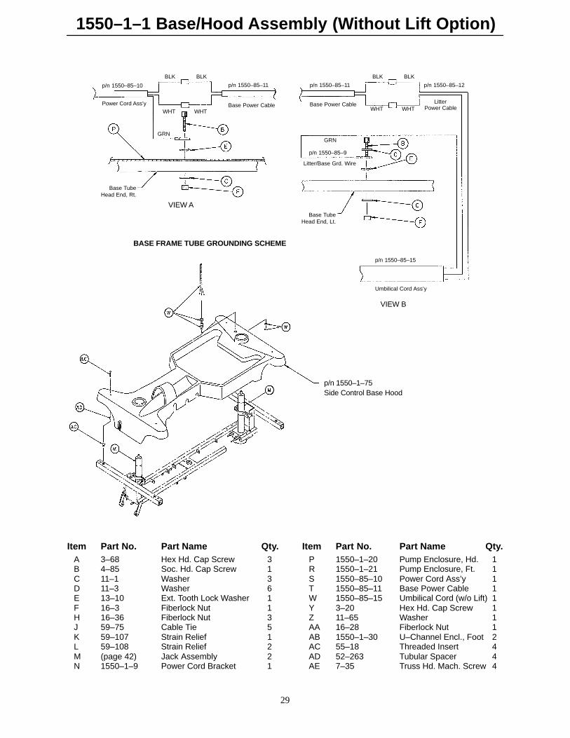
1550–1–1 Base/Hood Assembly (Without Lift Option)
29
p/n 1550–85–10
Power Cord Ass’y
BLK BLK
WHTWHT
p/n 1550–85–11
Base Power Cable
GRN
Base TubeHead End, Rt.
p/n 1550–85–11
Base Power Cable
BLK BLK
WHTWHT
p/n 1550–85–12
LitterPower Cable
GRN
p/n 1550–85–9
Litter/Base Grd. Wire
Base TubeHead End, Lt.
p/n 1550–85–15
Umbilical Cord Ass’y
BASE FRAME TUBE GROUNDING SCHEME
p/n 1550–1–75Side Control Base Hood
VIEW A
VIEW B
Item Part No. Part Name Qty. Item Part No. Part Name Qty.A 3–68 Hex Hd. Cap Screw 3 P 1550–1–20 Pump Enclosure, Hd. 1B 4–85 Soc. Hd. Cap Screw 1 R 1550–1–21 Pump Enclosure, Ft. 1C 11–1 Washer 3 S 1550–85–10 Power Cord Ass’y 1D 11–3 Washer 6 T 1550–85–11 Base Power Cable 1E 13–10 Ext. Tooth Lock Washer 1 W 1550–85–15 Umbilical Cord (w/o Lift) 1F 16–3 Fiberlock Nut 1 Y 3–20 Hex Hd. Cap Screw 1H 16–36 Fiberlock Nut 3 Z 11–65 Washer 1J 59–75 Cable Tie 5 AA 16–28 Fiberlock Nut 1K 59–107 Strain Relief 1 AB 1550–1–30 U–Channel Encl., Foot 2L 59–108 Strain Relief 2 AC 55–18 Threaded Insert 4M (page 42) Jack Assembly 2 AD 52–263 Tubular Spacer 4N 1550–1–9 Power Cord Bracket 1 AE 7–35 Truss Hd. Mach. Screw 4
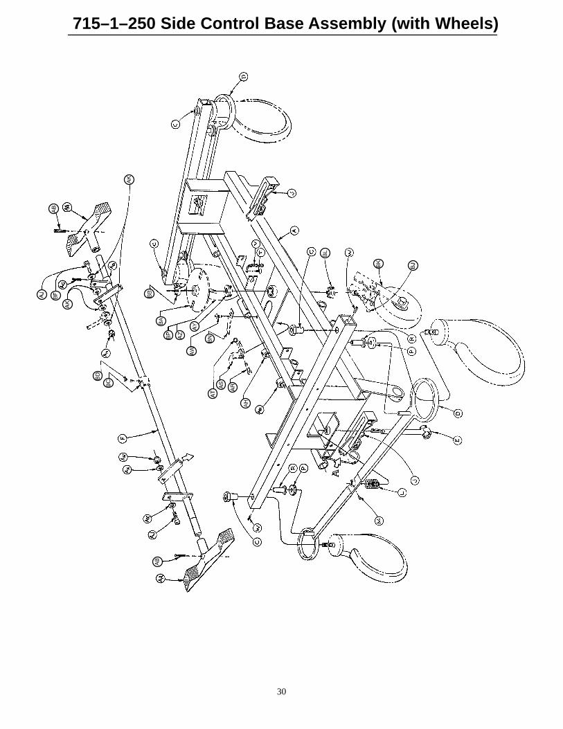
715–1–250 Side Control Base Assembly (with Wheels)
30

715–1–250 Side Control Base Assembly (with Wheels)
31
Item Part No. Part Name Qty.A 715–1–245 Base Weldment Assembly 1B 38–211 Spring 1C 715–1–158 Caster Nut 4D 715–1–61 Caster Brake Assembly 2E (Page 32) Brake Adjuster Assembly 2F 715–1–231 Brake/Steering Rod Assembly 1H 1000–10–62 Steering Lock Linkage Bar 1J (Page 33) Brake Cam Assembly 2L 715–1–94 Compression Spring 2M 21–50 Set Screw 2P 715–1–11 Brake Cushion 4R 946–1–116 Brake Bar Bushing 4T 23–25 Self–Tapping Screw 1V 715–1–156 Grounding Chain 1W 26–5 Roll Pin 4AA 715–1–201 Brake/Steer Pedal 2AB 26–196 Groove Pin 1AC 26–13 Roll Pin 1AD 715–1–165 Actuator Plate Assembly 1AH 42–20 Collar w/ Set Screw 2AJ 8–17 Soc. Hd. Cap Screw 2*AK 14–2 Nylon Washer 4AN 16–2 Fiberlock Nut 2AR 3–20 Hex Hd. Cap Screw 1AS 715–1–217 Fifth Wheel Latch 1AT 16–16 Nylock Nut 1AW 7–4 Truss Hd. Mach. Screw 1AY 715–1–157 Fifth Wheel Bearing 1AZ (Page 34) Steering Caster Assembly 1**BA 715–1–337 Fifth Wheel Plate Assembly 1BB 16–49 Flexlock Nut 1BC 715–1–161 Fifth Wheel Cam 1BD 26–8 Roll Pin 1BF 8–21 Soc. Hd. Cap Screw 1**BJ 715–1–149 Woodruff Key 1BK (Page 36) Fifth Wheel Assembly 1BL 81–219 Bearing 1BN 715–1–136 Fifth Wheel Spring 1BP (Page 35) Caster Wheel Assembly 3 ***
* Item AJ to be used only when fifth wheel is ordered. **Items AZ and BF to be used only when steerlock caster is ordered. *** Item BP quantity of four when fifth wheel is ordered.
STEERLOCKASSEMBLYDETAIL
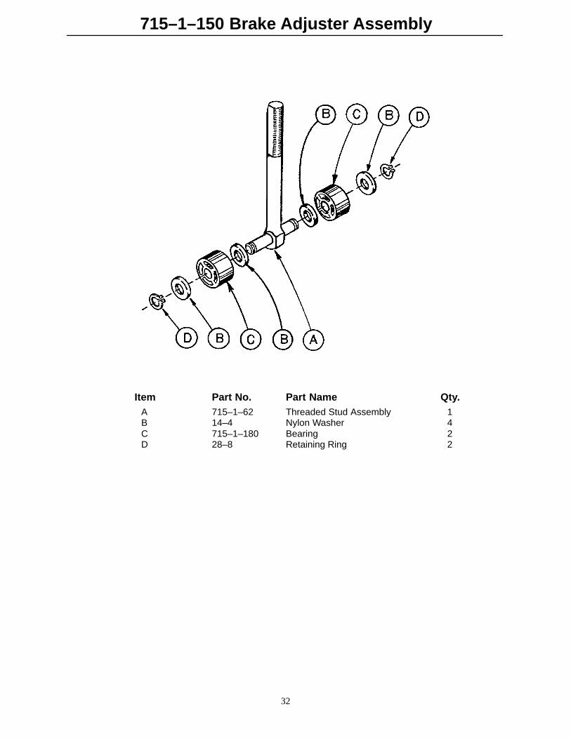
715–1–150 Brake Adjuster Assembly
32
Item Part No. Part Name Qty.A 715–1–62 Threaded Stud Assembly 1B 14–4 Nylon Washer 4C 715–1–180 Bearing 2D 28–8 Retaining Ring 2

715–1–213 Brake Cam Assembly
33
Item Part No. Part Name Qty.A 715–1–221 Brake Cam 1B 16–59 Fiberlock Nut 1C 8–21 Soc. Hd. Cap Screw 1D 715–1–173 Brake Connecting Link 1
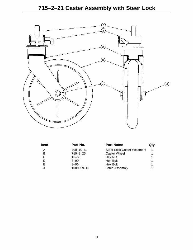
715–2–21 Caster Assembly with Steer Lock
34
Item Part No. Part Name Qty.A 700–10–50 Steer Lock Caster Weldment 1B 715–2–25 Caster Wheel 1C 16–60 Hex Nut 1D 3–99 Hex Bolt 1E 3–96 Hex Bolt 1J 1000–59–10 Latch Assembly 1
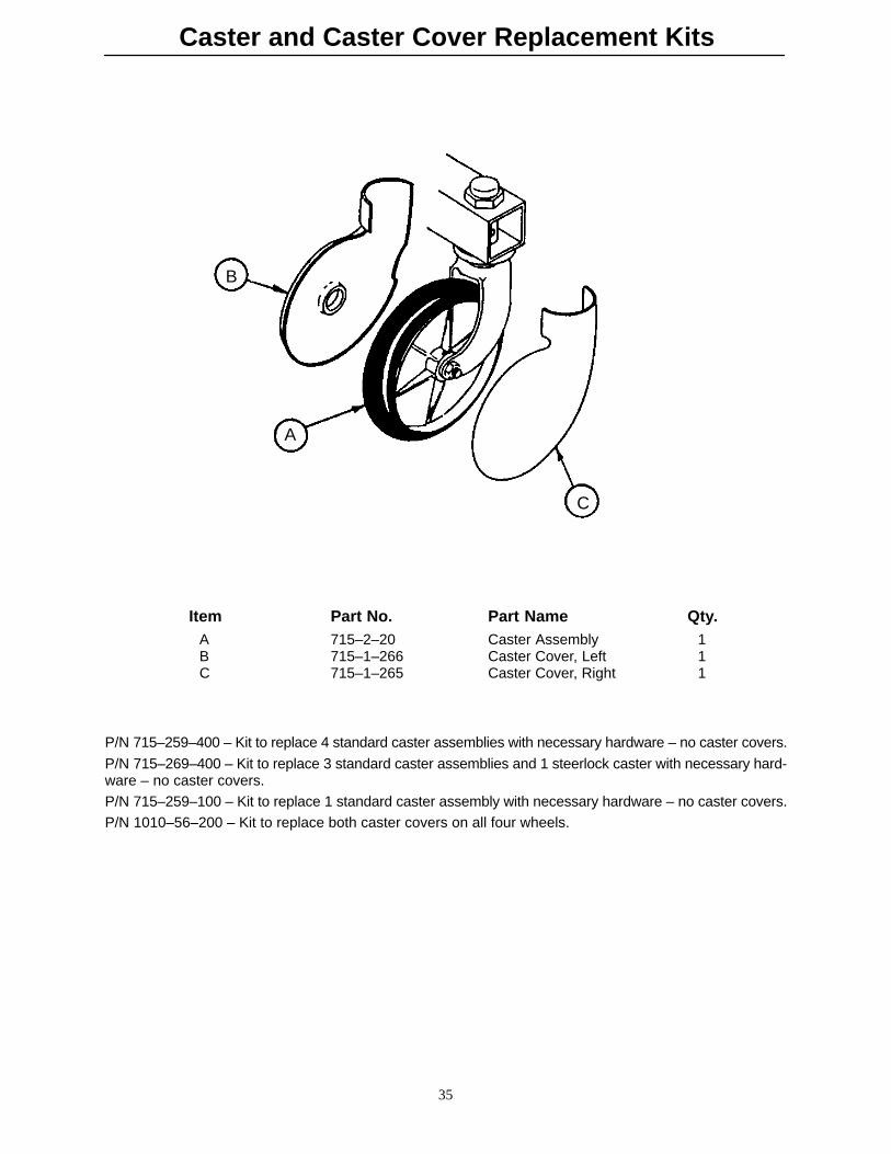
Caster and Caster Cover Replacement Kits
35
B
A
C
Item Part No. Part Name Qty.A 715–2–20 Caster Assembly 1B 715–1–266 Caster Cover, Left 1C 715–1–265 Caster Cover, Right 1
P/N 715–259–400 – Kit to replace 4 standard caster assemblies with necessary hardware – no caster covers.
P/N 715–269–400 – Kit to replace 3 standard caster assemblies and 1 steerlock caster with necessary hard-ware – no caster covers.P/N 715–259–100 – Kit to replace 1 standard caster assembly with necessary hardware – no caster covers.P/N 1010–56–200 – Kit to replace both caster covers on all four wheels.

715–1–25 Fifth Wheel Assembly
36
Item Part No. Part Name Qty.A 715–1–339 Fifth Wheel Pivot Assembly 1B 715–1–17 Fifth Wheel Bushing 1C 16–11 Flexlock Nut 1D 715–1–15 Spring 1E 715–1–13 Fifth Wheel Bracket 2F 16–12 Flexlock Nut 1G 390–1–54 Wheel 1H 3–31 Hex Head Cap Screw 1J 3–82 Hex Head Cap Screw 1

Notes
37
38
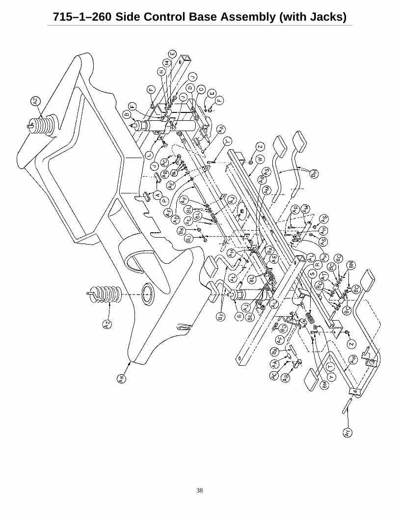
715–1–260 Side Control Base Assembly (with Jacks)A
Z
39
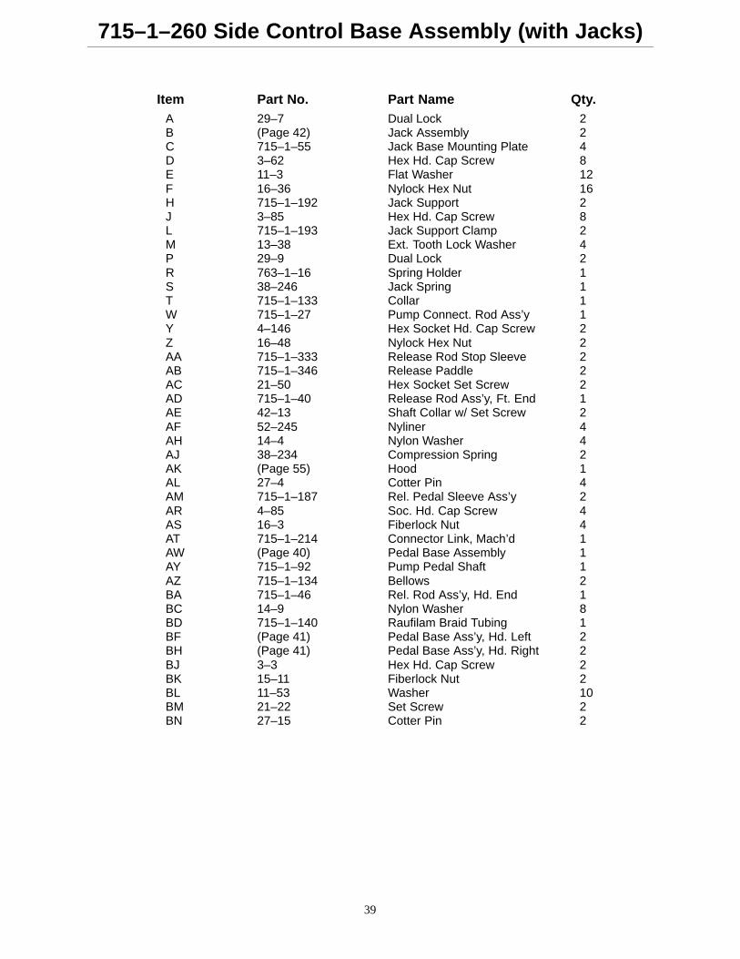
715–1–260 Side Control Base Assembly (with Jacks)
Item Part No. Part Name Qty.A 29–7 Dual Lock 2B (Page 42) Jack Assembly 2C 715–1–55 Jack Base Mounting Plate 4D 3–62 Hex Hd. Cap Screw 8E 11–3 Flat Washer 12F 16–36 Nylock Hex Nut 16H 715–1–192 Jack Support 2J 3–85 Hex Hd. Cap Screw 8L 715–1–193 Jack Support Clamp 2M 13–38 Ext. Tooth Lock Washer 4P 29–9 Dual Lock 2R 763–1–16 Spring Holder 1S 38–246 Jack Spring 1T 715–1–133 Collar 1W 715–1–27 Pump Connect. Rod Ass’y 1Y 4–146 Hex Socket Hd. Cap Screw 2Z 16–48 Nylock Hex Nut 2AA 715–1–333 Release Rod Stop Sleeve 2AB 715–1–346 Release Paddle 2AC 21–50 Hex Socket Set Screw 2AD 715–1–40 Release Rod Ass’y, Ft. End 1AE 42–13 Shaft Collar w/ Set Screw 2AF 52–245 Nyliner 4AH 14–4 Nylon Washer 4AJ 38–234 Compression Spring 2AK (Page 55) Hood 1AL 27–4 Cotter Pin 4AM 715–1–187 Rel. Pedal Sleeve Ass’y 2AR 4–85 Soc. Hd. Cap Screw 4AS 16–3 Fiberlock Nut 4AT 715–1–214 Connector Link, Mach’d 1AW (Page 40) Pedal Base Assembly 1AY 715–1–92 Pump Pedal Shaft 1AZ 715–1–134 Bellows 2BA 715–1–46 Rel. Rod Ass’y, Hd. End 1BC 14–9 Nylon Washer 8BD 715–1–140 Raufilam Braid Tubing 1BF (Page 41) Pedal Base Ass’y, Hd. Left 2BH (Page 41) Pedal Base Ass’y, Hd. Right 2BJ 3–3 Hex Hd. Cap Screw 2BK 15–11 Fiberlock Nut 2BL 11–53 Washer 10BM 21–22 Set Screw 2BN 27–15 Cotter Pin 2
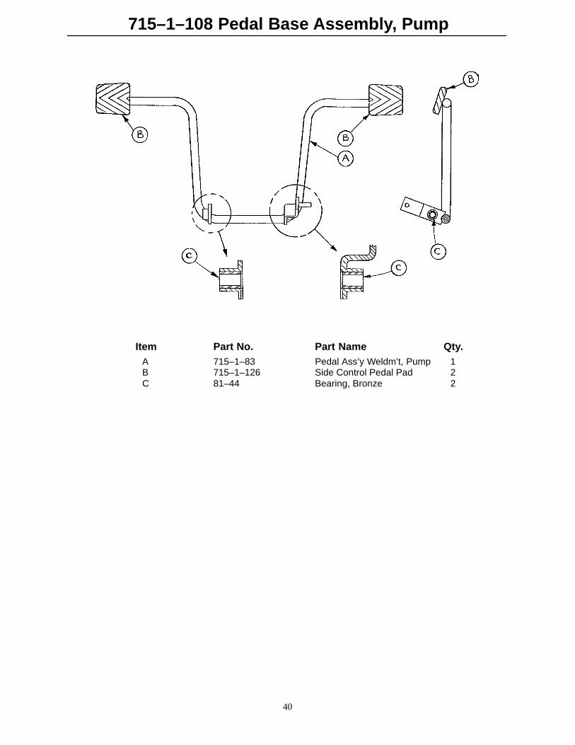
715–1–108 Pedal Base Assembly, Pump
40
Item Part No. Part Name Qty.A 715–1–83 Pedal Ass’y Weldm’t, Pump 1B 715–1–126 Side Control Pedal Pad 2C 81–44 Bearing, Bronze 2
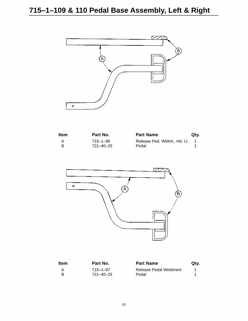
715–1–109 & 110 Pedal Base Assembly, Left & Right
41
Item Part No. Part Name Qty.A 715–1–98 Release Ped. Wldmt., Hd. Lt. 1B 721–40–25 Pedal 1
Item Part No. Part Name Qty.A 715–1–97 Release Pedal Weldment 1B 721–40–25 Pedal 1
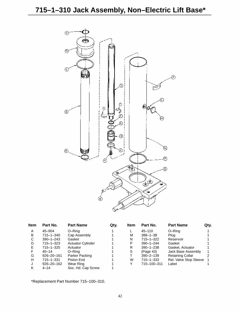
715–1–310 Jack Assembly, Non–Electric Lift Base*
42
Item Part No. Part Name Qty. Item Part No. Part Name Qty.A 45–904 O–Ring 1 L 45–110 O–Ring 1B 715–1–340 Cap Assembly 1 M 388–1–38 Plug 1C 390–1–243 Gasket 1 N 715–1–322 Reservoir 1D 715–1–323 Actuator Cylinder 1 P 390–1–244 Gasket 1E 715–1–325 Actuator 1 R 390–1–238 Gasket, Actuator 1F 45–14 O–Ring 1 S (Page 43) Jack Base Assembly 1G 926–20–161 Parker Packing 1 T 390–2–139 Retaining Collar 2H 715–1–331 Piston End 1 W 715–1–333 Rel. Valve Stop Sleeve 1J 926–20–162 Wear Ring 1 Y 715–100–311 Label 1K 4–14 Soc. Hd. Cap Screw 1
*Replacement Part Number 715–100–310.

715–1–300 Jack Base Assembly, Non–Electric Lift Base
43
AF
Item Part No. Part Name Qty. Item Part No. Part Name Qty.A 715–1–312 Base, Machined 1 R 45–110 O–Ring 1B 715–1–308 Base Plug 1 S 715–1–328 Piston Wear Ring 1C 715–1–306 Pin 1 T 14–50 Bearing Retainer 1D 28–8 Snap Ring 1 W 715–1–327 Cylinder Wear Ring 1E 390–2–176 Washer 1 X 715–1–316 Pump Cylinder 1F 38–231 Compression Spring 1 Y 715–1–329 Pump Seal 1H 45–6 O–Ring 2 AA 715–1–307 Needle Valve 1J 715–1–305 Pin Housing 1 AB 926–20–156 Seal 2K 715–1–330 Housing Gasket 1 AC 715–1–301 Base Plug 2L 715–1–309 Valve Plug 2 AD 715–1–341 Poppet 1M 926–20–153 Check Valve 2 AE 390–2–134 Conical Comp. Spring 1N 926–20–154 Seal 2 AF 715–100–312 Pin Housing Assembly 1P 715–1–318 Pump Piston 1
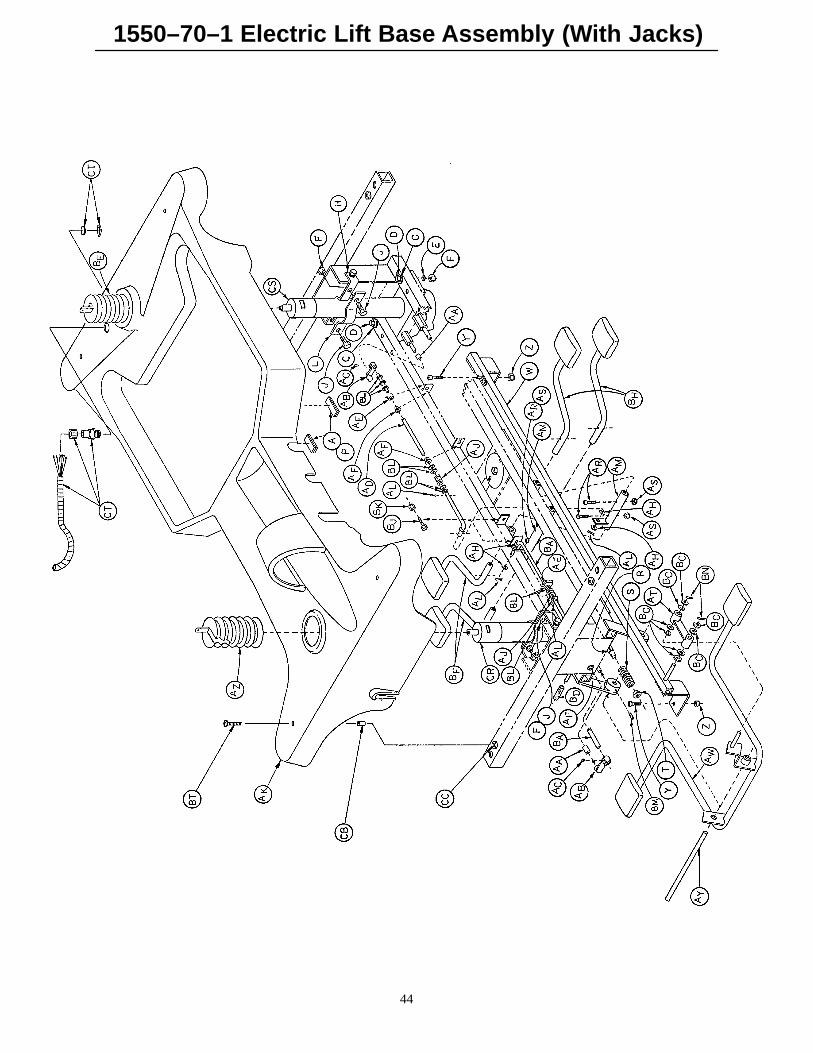
1550–70–1 Electric Lift Base Assembly (With Jacks)
44
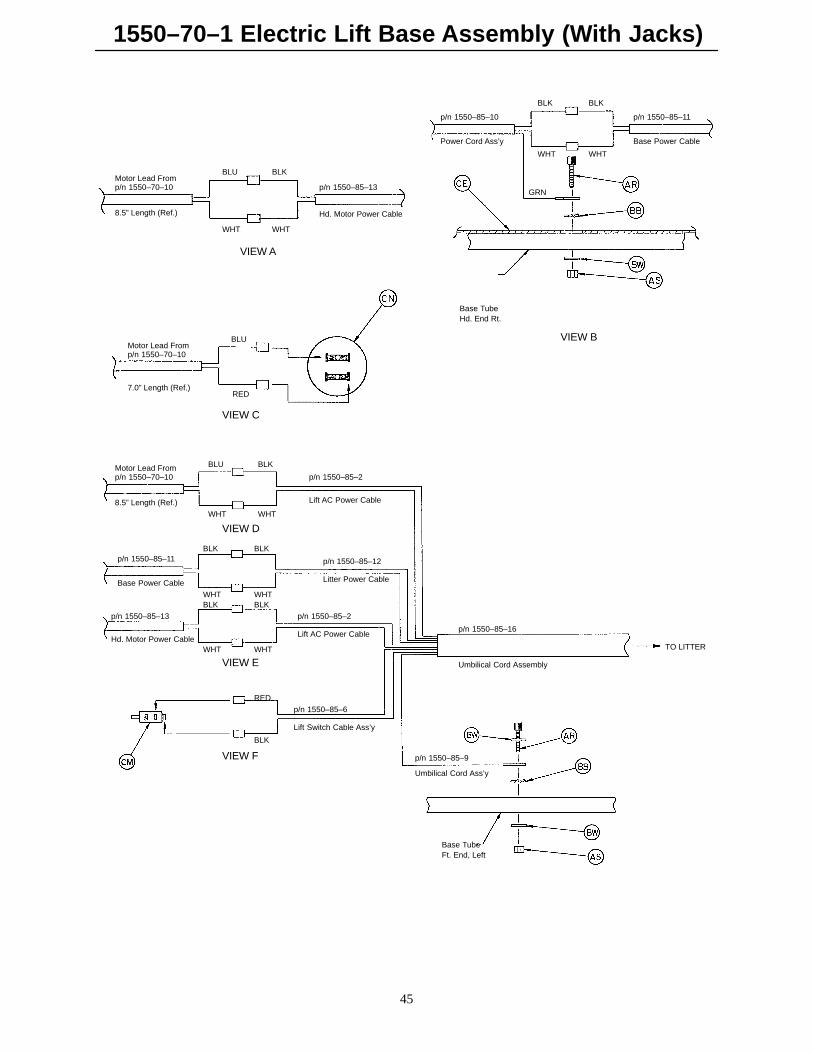
1550–70–1 Electric Lift Base Assembly (With Jacks)
45
Motor Lead Fromp/n 1550–70–10
BLU BLK
WHTWHT
p/n 1550–85–13
Hd. Motor Power Cable
VIEW A
Base TubeHd. End Rt.
GRN
BLK BLK
WHTWHT
p/n 1550–85–10 p/n 1550–85–11
Base Power CablePower Cord Ass’y
VIEW B
VIEW C
BLU
RED
Motor Lead Fromp/n 1550–70–10
8.5” Length (Ref.)
7.0” Length (Ref.)
TO LITTER
VIEW D
VIEW E
VIEW F
Base TubeFt. End, Left
Motor Lead Fromp/n 1550–70–10
8.5” Length (Ref.)
BLU BLK
WHTWHT
p/n 1550–85–2
Lift AC Power Cable
BLK BLK
WHTWHTBLK BLK
WHTWHT
p/n 1550–85–11
Base Power Cable
p/n 1550–85–12
Litter Power Cable
p/n 1550–85–13
Hd. Motor Power Cable
p/n 1550–85–2
Lift AC Power Cablep/n 1550–85–16
Umbilical Cord Assembly
RED
BLK
p/n 1550–85–6
Lift Switch Cable Ass’y
p/n 1550–85–9
Umbilical Cord Ass’y
1550–70–1 Electric L
ift Base A
ssemb
ly (With
Jacks)
46
HEAD END
TO UMBILICALCORD ASS”Y
TO UMBILICALCORD ASS”Y
TO UMBILICALCORD ASS”Y
TO UMBILICALCORD ASS”Y
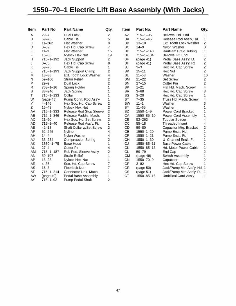
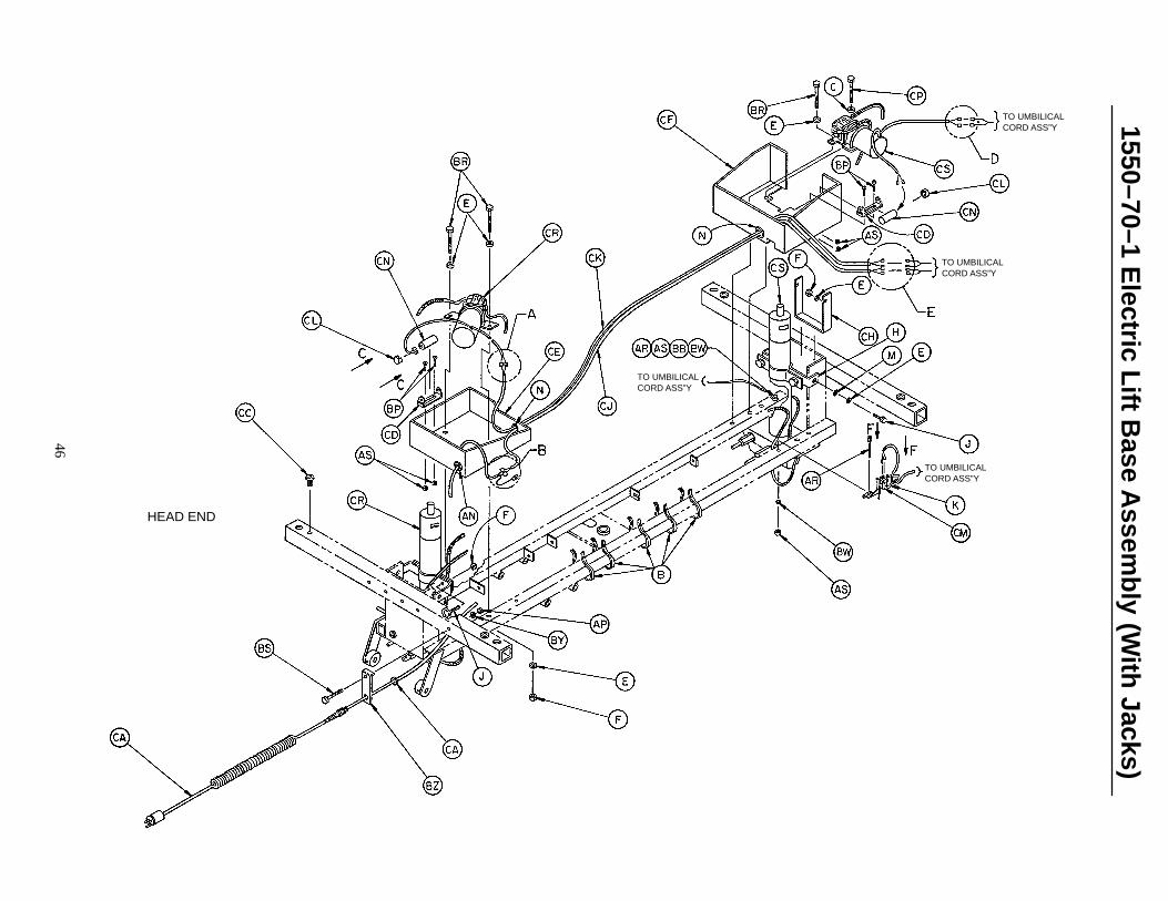
1550–70–1 Electric Lift Base Assembly (With Jacks)
47
Item Part No. Part Name Qty. Item Part No. Part Name Qty.A 29–7 Dual Lock 2 AZ 715–1–95 Bellows, Hd. End 1B 59–75 Cable Tie 5 BA 715–1–46 Release Rod Ass’y, Hd. 1C 11–262 Flat Washer 8 BB 13–10 Ext. Tooth Lock Washer 2D 3–62 Hex Hd. Cap Screw 7 BC 14–9 Nylon Washer 8E 11–3 Flat Washer 15 BD 715–1–140 Raufilam Braid Tubing 1F 16–36 Nylock Hex Nut 19 BE 715–1–134 Bellows, Ft. End 1H 715–1–192 Jack Support 2 BF (page 41) Pedal Base Ass’y, Lt. 2J 3–85 Hex Hd. Cap Screw 8 BH (page 41) Pedal Base Ass’y, Rt. 2K 59–76 Cable Tie 1 BJ 3–3 Hex Hd. Cap Screw 2L 715–1–193 Jack Support Clamp 2 BK 15–11 Hex Nut 2M 13–38 Ext. Tooth Lock Washer 4 BL 11–53 Washer 10N 59–106 Strain Relief 2 BM 21–22 Set Screw 2P 29–9 Dual Lock 2 BN 27–15 Cotter Pin 2R 763–1–16 Spring Holder 1 BP 1–21 Flat Hd. Mach. Screw 4S 38–246 Jack Spring 1 BR 3–68 Hex Hd. Cap Screw 3T 715–1–133 Collar 1 BS 3–20 Hex Hd. Cap Screw 1W (page 48) Pump Conn. Rod Ass’y 1 BT 7–35 Truss Hd. Mach. Screw 4Y 4–146 Hex Soc. Hd. Cap Screw 2 BW 11–1 Washer 3Z 16–48 Nylock Hex Nut 2 BY 11–65 Washer 1AA 715–1–333 Release Rod Stop Sleeve 2 BZ 1550–1–9 Power Cord Bracket 1AB 715–1–346 Release Paddle, Mach. 2 CA 1550–85–10 Power Cord Assembly 1AC 21–50 Hex Soc. Hd. Set Screw 2 CB 52–263 Tubular Spacer 4AD 715–1–40 Release Rod Ass’y, Ft. 1 CC 55–18 Threaded Insert 4AE 42–13 Shaft Collar w/Set Screw 2 CD 59–80 Capacitor Mtg. Bracket 2AF 52–245 Nyliner 4 CE 1550–1–20 Pump Encl., Hd. 1AH 14–4 Nylon Washer 4 CF 1550–1–21 Pump Encl., Ft. 1AJ 38–234 Compression Spring 2 CH 1550–1–30 U–Channel Encl., Ft. 1AK 1550–1–75 Base Hood 1 CJ 1550–85–11 Base Power Cable 1AL 27–4 Cotter Pin 4 CK 1550–85–13 Hd. Motor Power Cable 1AM 715–1–187 Rel. Ped. Sleeve Ass’y 2 CL 59–79 End Cap 2AN 59–107 Strain Relief 1 CM (page 49) Switch Assembly 1AP 16–28 Nylock Hex Nut 1 CN 1550–70–9 Capacitor 2AR 4–85 Soc. Hd. Cap Screw 7 CP 3–82 Hex Hd. Cap Screw 1AS 16–3 Fiberlock Nut 7 CR (page 50) Jack/Pump Mtr. Ass’y, Hd. 1AT 715–1–214 Connector Link, Mach. 1 CS (page 51) Jack/Pump Mtr. Ass’y, Ft. 1AW (page 40) Pedal Base Assembly 1 CT 1550–85–16 Umbilical Cord Ass’y 1AY 715–1–92 Pump Pedal Shaft 2
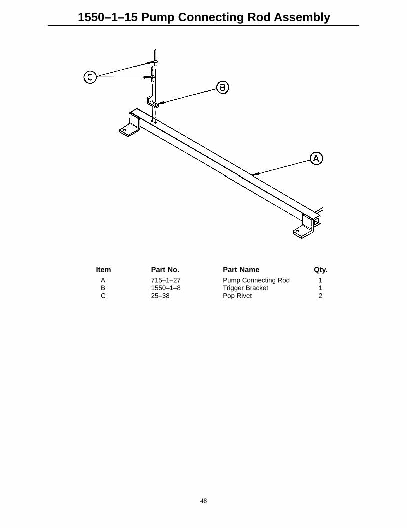
1550–1–15 Pump Connecting Rod Assembly
48
Item Part No. Part Name Qty.A 715–1–27 Pump Connecting Rod 1B 1550–1–8 Trigger Bracket 1C 25–38 Pop Rivet 2
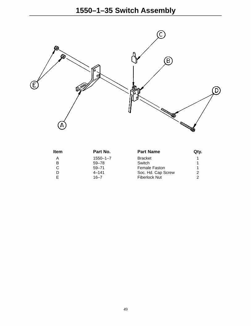
1550–1–35 Switch Assembly
49
Item Part No. Part Name Qty.A 1550–1–7 Bracket 1B 59–78 Switch 1C 59–71 Female Faston 1D 4–141 Soc. Hd. Cap Screw 2E 16–7 Fiberlock Nut 2

1550–70–30 Jack/Pump Motor Assembly, Head End
50
VIEW A VIEW B VIEW C
Item Part No. Part Name Qty.A (page 52) Jack Assembly 1B 1550–70–10 Pump/Motor Assembly 1C 1550–70–2 Pressure Line 1D 1550–70–3 Return Line 1E 48–144 90� Elbow O–Ring Fitting 2F 1550–1–29 U–Bolt, Pump/Motor 2H 3–47 Hex Hd. Cap Screw 2J 52–70 Nylon Shoulder Washer 2K 1550–1–28 U–Bracket Mount 1L 1550–1–22 Pump Mount Stand–Off 2M 1550–1–26 Pump Bracket, Hd. End 1N 11–224 Nylon Washer 2P 16–28 Fiberlock Hex Nut 6R 48–146 90� Elbow O–Ring Fitting 1
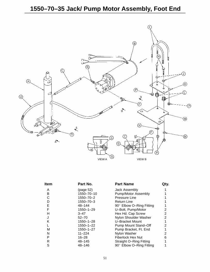
1550–70–35 Jack/ Pump Motor Assembly, Foot End
51
VIEW A VIEW B
Item Part No. Part Name Qty.A (page 52) Jack Assembly 1B 1550–70–10 Pump/Motor Assembly 1C 1550–70–2 Pressure Line 1D 1550–70–3 Return Line 1E 48–144 90� Elbow O–Ring Fitting 1F 1550–1–29 U–Bolt, Pump/Motor 2H 3–47 Hex Hd. Cap Screw 2J 52–70 Nylon Shoulder Washer 2K 1550–1–28 U–Bracket Mount 1L 1550–1–22 Pump Mount Stand–Off 2M 1550–1–27 Pump Bracket, Ft. End 1N 11–224 Nylon Washer 2P 16–28 Fiberlock Hex Nut 6R 48–145 Straight O–Ring Fitting 1S 48–146 90� Elbow O–Ring Fitting 1

1550–70–25 Jack Assembly, Electric Lift Base
52
Item Part No. Part Name Qty. Item Part No. Part Name Qty.A 45–904 O–Ring 1 K 4–14 Soc. Hd. Cap Screw 1B 1550–70–6 Cap Assembly 1 L 45–110 O–Ring 1C 390–1–243 Gasket 1 M 388–1–38 Plug 1D 1550–70–4 Actuator Cylinder 1 N 715–1–322 Reservoir 1E 715–1–325 Actuator 1 P 390–1–244 Gasket 1F 45–14 O–Ring 1 R 390–1–238 Gasket, Actuator 1G 926–20–161 Parker Packing 1 S (page 53) Jack Base Assembly 1H 715–1–331 Piston End 1 T 390–2–139 Retaining Collar 2J 926–20–162 Wear Ring 1 W 1550–90–11 Label 1
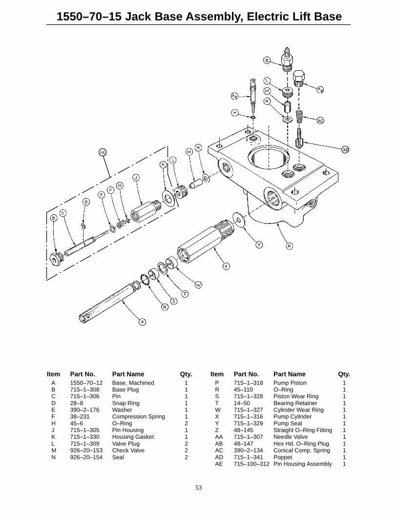
1550–70–15 Jack Base Assembly, Electric Lift Base
53
AE
Item Part No. Part Name Qty. Item Part No. Part Name Qty.A 1550–70–12 Base, Machined 1 P 715–1–318 Pump Piston 1B 715–1–308 Base Plug 1 R 45–110 O–Ring 1C 715–1–306 Pin 1 S 715–1–328 Piston Wear Ring 1D 28–8 Snap Ring 1 T 14–50 Bearing Retainer 1E 390–2–176 Washer 1 W 715–1–327 Cylinder Wear Ring 1F 38–231 Compression Spring 1 X 715–1–316 Pump Cylinder 1H 45–6 O–Ring 2 Y 715–1–329 Pump Seal 1J 715–1–305 Pin Housing 1 Z 48–145 Straight O–Ring Fitting 1K 715–1–330 Housing Gasket 1 AA 715–1–307 Needle Valve 1L 715–1–309 Valve Plug 2 AB 48–147 Hex Hd. O–Ring Plug 1M 926–20–153 Check Valve 2 AC 390–2–134 Conical Comp. Spring 1N 926–20–154 Seal 2 AD 715–1–341 Poppet 1
AE 715–100–312 Pin Housing Assembly 1
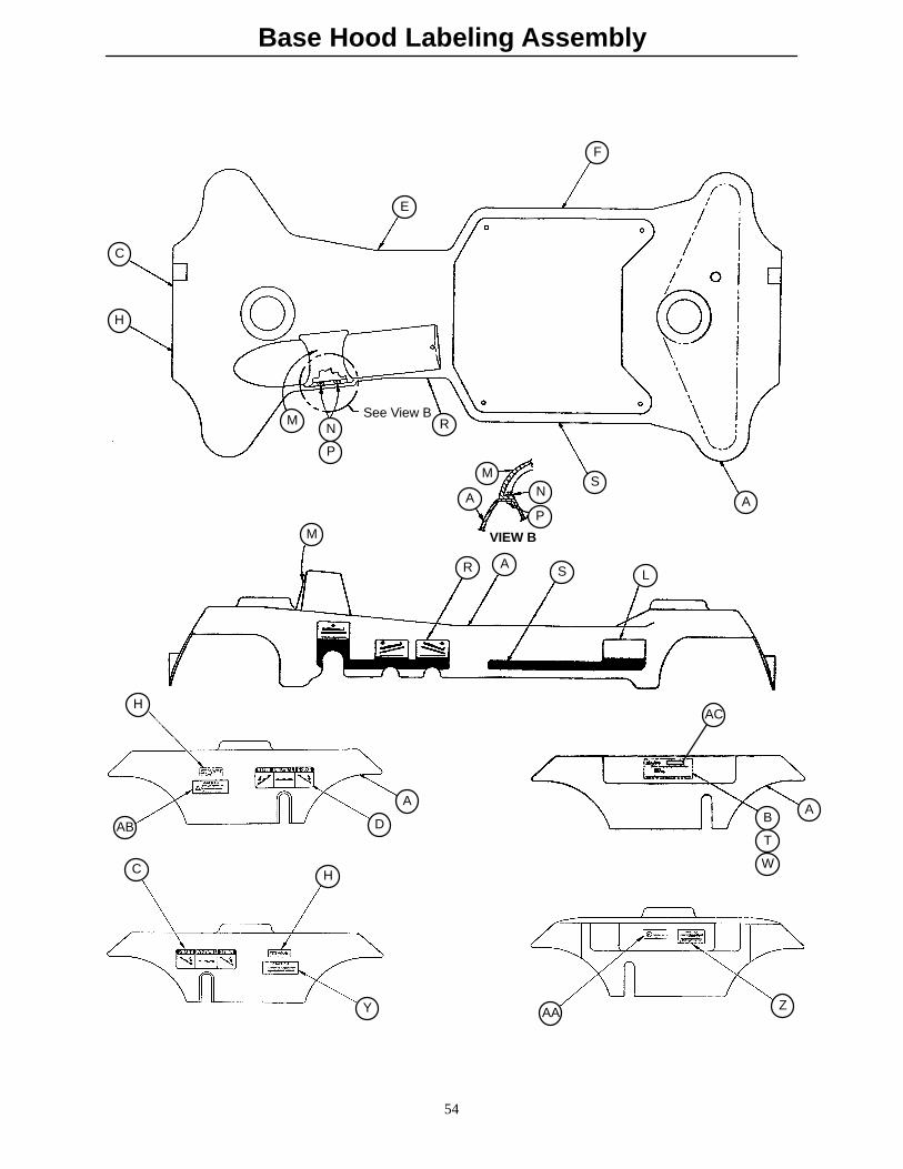
Base Hood Labeling Assembly
54
AB D
AB
A
See View B
VIEW B
H
C
E
F
A
SN
P
M
A
RN
P
M
M
R AS L
ACH
C H
Y AA Z
T
W
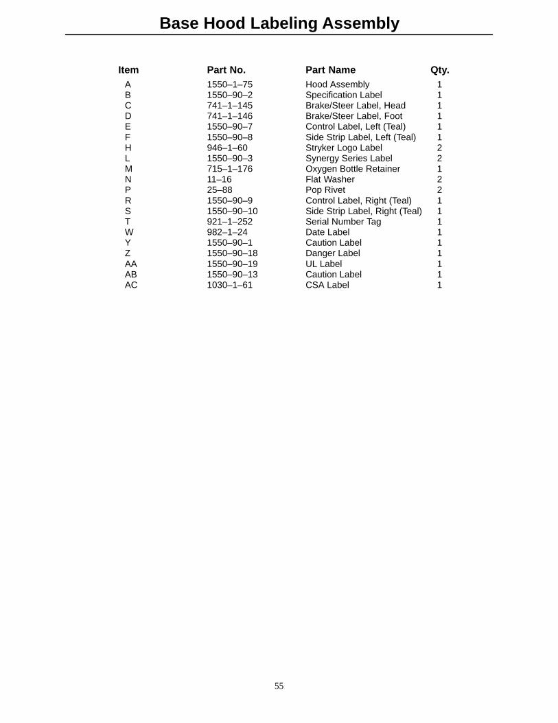
Base Hood Labeling Assembly
55
Item Part No. Part Name Qty.A 1550–1–75 Hood Assembly 1B 1550–90–2 Specification Label 1C 741–1–145 Brake/Steer Label, Head 1D 741–1–146 Brake/Steer Label, Foot 1E 1550–90–7 Control Label, Left (Teal) 1F 1550–90–8 Side Strip Label, Left (Teal) 1H 946–1–60 Stryker Logo Label 2L 1550–90–3 Synergy Series Label 2M 715–1–176 Oxygen Bottle Retainer 1N 11–16 Flat Washer 2P 25–88 Pop Rivet 2R 1550–90–9 Control Label, Right (Teal) 1S 1550–90–10 Side Strip Label, Right (Teal) 1T 921–1–252 Serial Number Tag 1W 982–1–24 Date Label 1Y 1550–90–1 Caution Label 1Z 1550–90–18 Danger Label 1AA 1550–90–19 UL Label 1AB 1550–90–13 Caution Label 1AC 1030–1–61 CSA Label 1

Side Control Graphics
1
B
D
A
CA
C
Reference below fordept. label part numbers.
Color Item A ControlLabel, Right
Item B ControlLabel, Left
Item C StripeLabel, Right
Item D StripeLabel, Left
Litter Bumper
RED 1010–700–11 1010–700–12 1010–700–13 1010–700–14 1010–700–15
PURPLE 1010–700–21 1010–700–22 1010–700–23 1010–700–24 1010–700–25
GREEN 1010–700–31 1010–700–32 1010–700–33 1010–700–34 1010–700–35
GRAY 1010–700–41 1010–700–42 1010–700–43 1010–700–44 1010–700–45
TEAL 1010–700–51 1010–700–52 1010–700–53 1010–700–54 1010–700–55
PINK 1010–700–61 1010–700–62 1010–700–63 1010–700–64 1010–700–65
BLUE 1010–700–71 1010–700–72 1010–700–73 1010–700–74 1010–700–75
Department Label Part Number Department Label Part NumberEmergency 1010–900–1 Endoscopy 1010–900–7P.A.C.U. 1010–900–2 Radiology 1010–900–8Transport 1010–900–3 Nuclear Medicine 1010–900–9Surgery 1010–900–4 Ambulatory Surgery 1010–900–10Extended Stay 1010–900–5 G.I. Lab 1010–900–11Maternity 1010–900–6 Cath. Lab 1010–900–12
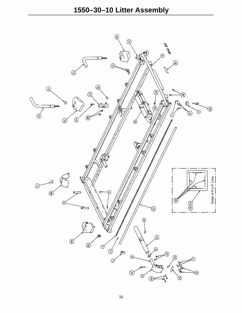
1550–30–10 Litter Assembly
56
Det
ail o
f P.U
.P. L
iner

1550–30–10 Litter Assembly
57
1550–34–7 (Ref.)
1550–33–28 (Ref.)

1550–30–10 Litter Assembly
58

1550–30–10 Litter Assembly
59
1550–85–1Switch Cable(Ref.)
1550–85–16 Powered Base1550–85–15 Non–Powered Base
1550–85–1Switch Cable(Ref.)
1550–85–8Head End Lockout Cable (Ref.)
1550–85–1Switch Cable(Ref.)

1550–30–10 Litter Assembly
60
Item Part No. Part Name Qty. Item Part No. Part Name Qty.A 1550–30–5 Frame Assembly 1 CH 3–41 Hex Hd. Cap Screw 2B 938–1–401 Collar 2 CJ 1550–90–14 Litter Fuse Label 1C 28–23 Retaining Ring 2 CK 3–47 Hex Hd. Cap Screw 20D 1001–40–12 Foot Board Receptacle 2 CL 37–59 Hole Plug 2E 23–104 Self–Tapping Screw 8 CM 14–3 Washer 3F 926–400–42 Corner Wheel 4 CN 4–32 Soc. Hd. Cap Screw 4H 1001–32–19 Wheel Housing 2 CP 4–101 Soc. Hd. Cap Screw 6J 1010–201–27 Bumper Extrusion 2 CR 25–79 Pop Rivet 6K 1001–1–36 End Plug 2 CS 1010–32–92 Foley Bag Rack 2L 1001–1–41 Tube Plug 2 CT 4–173 But. Hd. Cap Screw 12M 46–1 Sq. Hd. Set Screw 1 CW 7–20 Truss Hd. Mach. Screw 6N 1010–32–64 Carrier Tube, Std. 2 CZ 8–15 Shoulder Bolt 1P 4–100 Soc. Hd. Cap Screw 2 DA 13–10 Ext. Tooth Lock Washer 12R 919–30–28 Rack Guide 2 DB 1010–254–16 P.U.P. Liner 8S 1010–201–50 Support Roller 4 DC 13–18 Ext. Tooth Lock Washer 4T 721–32–107 Roller Sleeve 4 DD 14–2 Washer 12W (page 62) Jack Supt./Trend. Limiter 1 DE 1550–90–15 Caution Label 2Z 1–110 Flat Hd. Screw 4 DF 16–14 Nylock Nut 2AA 3–76 Hex Soc. Hd. Screw 4 DH 23–25 Hex Hd. Tap. Screw 8AB 16–28 Nylock Nut 56 DJ 25–122 Pop Rivet 35AC 3–40 Hex Hd. Cap Screw 2 DK 16–23 Lock Nut 2AD 16–11 Flexlock Nut 4 DL 26–12 Roll Pin 2AE 1550–26–18 Oval Sleeve 2 DM 30–33 Grommet Edging 2.7’AF 38–282 Disc Spring 8 DN 37–49 Hole Plug 2AH 16–35 Nylock Nut 4 DP 52–89 Fil. Slotted Nylon Screw 6AJ 25–38 Pop Rivet 20 DR 52–91 Female Spacer 6AK 4–201 Soc. Hd. Cap Screw 4 DS 59–54 5– Pin Housing 2AL 1550–26–24 Lock Support 2 DT 59–68 Rocker Switch 2AM 721–26–66 Pivot Screw 14 DW 59–69 Terminal Faston 4AN 721–26–69 Upright Sleeve 4 DZ 59–70 6–Pin Housing 1AP 4–136 But. Hd. Cap Screw 14 EA 59–72 Nylon Key Plug 1AR 4–135 But. Hd. Cap Screw 4 EB 59–74 Strain Relief Bushing 4AS 38–220 Compression Spring 2 EC 59–76 Nylon Cable Tie 2AT 1010–26–81 Lock Hsg. Ass’y, Lt. 1 ED 59–77 Yellow LED 2AW 1010–26–80 Lock Hsg. Ass’y, Rt. 1 EF 36–46 Ground Label 1AZ 14–21 Nylon Flat Washer 2 EH 59–100 Dome Plug 2BA 11–179 Nylon Flat Washer 6 EJ 1550–90–20 O2 Caution Label 2BB 37–74 Hole Plug 2 EK 460–2–32 Ground Strap 2BC 721–26–74 Lock Handle, Mach. 2 EL 1510–34–90 Slider Pad 2BD 21–104 Set Screw 2 EM 1510–34–94 Calf Stand Rest 2BE 11–2 Flat Washer 2 EN 946–1–155 Bumper 2BF 1501–27–23 Supt. Tube Ass’y 1 EP 988–2–676 Earth Ground Jumper 1BH 1501–31–13 Fowler Tube 1 ER 1001–34–25 Hole Plug 4BJ 4–183 Fowler Pivot Bolt 2 ES (page 73) Push Handle Assembly 2BK 1010–201–236 Corner Cover, Hole/Slot 1 ET 1501–33–24 Fowler Lever Assembly 1BL 1010–201–237 Corner Cover, Hole/Hole 1 EW 1501–34–21 Thigh Frame Assembly 1BM 1010–201–238 Corner Cover, Slot Only 1 EZ 1501–34–22 Calf Frame Assembly 1BN 1010–201–239 Corner Cover, Hole Only 1 FA 1501–34–23 Midsection Supt. Ass’y 1BP 1510–231–12 Fowler Skin 1 FB 1510–234–26 Calf Skin 1BR (page 74) Siderail Assembly, Lt. 1 FC 1510–234–27 Midsection Skin 1BS (page 74) Siderail Assembly, Rt. 1 FD 1510–234–28 Thigh Skin 1BT 946–1–60 Logo Label 1 FE 1550–30–21 Siderail Bumper (Teal) 2BW 3–50 Hex Hd. Cap Screw 4 FF 1550–1–31 Weigh Board Cover 1BZ 37–10 Hole Plug 2 FH 1550–26–9 Top Rail Nurse Label, Rt. 1CA 1010–254–4 Receptacle Ass’y, Lt. 1 FJ 1550–26–10 Top Rail Nurse Label, Lt. 1CB 1010–254–6 Receptacle Ass’y, Rt. 1 FK (page 75) Comp. Hsg. Ass’y, Rt. 1CC 25–50 Pop Rivet 7 FL (page 76) Comp. Hsg. Ass’y, Lt. 1CD 3–78 Hex Hd. Cap Screw 6 FM 1550–30–2 Board Housing Top 1CE 2–31 Round Hd. Mach. Screw 2 FN 1550–30–8 Board Housing Ass’y 1CF 26–57 Roll Pin 2 FP 1550–30–17 Hd. End Lockout Wldmt. 1

1550–30–10 Litter Assembly
61
Item Part No. Part Name Qty. Item Part No. Part Name Qty.FR 1550–30–25 Power Cord Hook 2 HD 1550–85–5 AC Motor Ground 1FS 1001–31–31 Pneumatic Fowler Rest 2 HE 1550–85–7 Ft. End Lockout Cable 1FT 23–100 Self–Tapping Screw 4 HF 1550–85–8 Hd. End Lockout Cable 1FW 1550–34–20 Crankscrew Mtg. Brkt. 4 HJ 1550–33–31 Fowler Supt. Ass’y 2FZ 1550–34–21 Thigh Support 2 HK 1550–90–5 Lockout Label 2HA 1550–80–900 Logic Control Board 1 HL 1550–90–13 Caution Label 1HB 1550–85–1 Switch Cable 2HC 1550–85–3 DC Ground 1

1550–35–1 Jack Support & Trend. Limiter Assembly
62
Item Part No. Part Name Qty.A 1550–35–2 Jack Supt. Ass’y, Rt. 1B 1550–35–3 Jack Supt. Ass’y, Lt. 1C 16–28 Nylock Nut 4D 3–15 Hex Hd. Cap Screw 4E (page 63) Trend. Limiter Ass’y 1F 1510–32–20 Support Tube Ass’y 1H 46–1 Set Screw 1

1550–35–5 Trend. Limiter Assembly
63
Item Part No. Part Name Qty.A 1550–35–6 Limiter Plate Assembly 1B 4–8 Hex Soc. Mach. Screw 1C 15–23 Hex Nut 1D 4–142 Hex Soc. Hd. Cap Screw 1E 715–1–114 Limiter Pin Assembly 1F 38–233 Extension Spring 1H 16–28 Fiberlock Nut 1
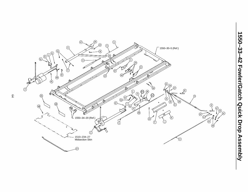
1550–33–42 Fo
wler/G
atch Q
uick D
rop
Assem
bly
64
1550–30–5 (Ref.)
1550–34–20 (Ref.)
1510–234–27Midsection Skin
AZ
BA

1550–33–42 Fowler/Gatch Quick Drop Assembly
65
Item Part No. Part Name Qty.A 1550–33–28 Drive Bar Weldment 1B 1550–33–14 Fowler Crkscr. Detent Ass’y 1C 1550–33–25 Quick Drop Brkt. Ass’y, Rt. 1D 1550–33–26 Quick Drop Brkt. Ass’y, Lt. 1E 1550–33–19 Release Arm Weldment 1F 1550–33–20 Handle Guard 2G 1550–33–36 Right Release Label 1H 1550–33–37 Left Release Label 1J 1550–33–38 E–Drop Release Label, Left 1K 1550–33–43 E–Drop Release Label, Right 1L 1550–33–11 Spring/Cable Pin 2M 1550–33–18 Cable Retainer 2N 1550–33–16 Cable Return Arm 2P 1550–33–29 Drive Tube Stop 3R 1550–33–8 Quick Drop Handle Grip 2S 1550–33–9 Fowler/Gatch Release Cable 2T 1550–34–16 Gatch Detent Arm Ass’y 1V 1550–34–7 Knee Gatch Ckscr. Extension 1W 1550–31–2 Threaded End Fitting 2X 1550–31–1 Fowler Gas Cylinder 1Y (page 66) Fow. Ckscr. Ass’y, w/ Act. 1Z (page 67) Gat. Ckscr. Ass’y, w/ Act. 1AA 1550–90–23 Reset Label, Fowler 1AB 1550–90–24 Reset Label, Gatch 1AC 4–5 Soc. Hd. Cap Screw 2AD 4–219 Soc. Hd. Cap Screw 3AE 16–47 Nylock Nut 2AF 21–8 Set Screw 4AG 38–285 Extension Spring 2AH 38–284 Extension Spring 2AJ 11–2 Washer 4AK 14–55 Washer 4AL 28–114 Retaining Ring 4AM 16–28 Nylock Nut 4AN 14–20 Washer 4AP 37–95 End Cap 2AR 3–47 Hex Hd. Cap Screw 4AS 25–79 Pop Rivet 8AT 1550–34–22 Cable Guide 1AV 59–76 Nylon Cable Tie 2AW 25–50 Pop Rivet 2AX 16–11 Flexlock Nut 1AY 3–68 Hex Hd. Cap Screw 1AZ 4–105 Hex Hd. Cap Screw 1BA 16–35 Nylock Nut 1
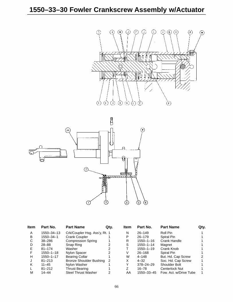
1550–33–30 Fowler Crankscrew Assembly w/Actuator
66
Item Part No. Part Name Qty. Item Part No. Part Name Qty.
A 1550–34–13 Crk/Coupler Hsg. Ass’y, Rt. 1 N 26–149 Roll Pin 1B 1550–34–1 Crank Coupler 1 P 26–179 Spiral Pin 1C 38–286 Compression Spring 1 R 1550–1–16 Crank Handle 1D 28–88 Snap Ring 2 S 1550–1–14 Magnet 1E 81–174 Washer 2 T 1550–1–19 Crank Knob 1F 1550–1–18 Nylon Spacer 2 V 26–168 Spiral Pin 1H 1550–1–17 Bearing Collar 1 W 4–148 But. Hd. Cap Screw 2J 81–213 Bronze Shoulder Bushing 2 X 4–32 Soc. Hd. Cap Screw 1K 11–45 Nylon Washer 1 Y 378–24–29 Shoulder Bolt 1L 81–212 Thrust Bearing 1 Z 16–78 Centerlock Nut 1M 14–44 Steel Thrust Washer 2 AA 1550–33–45 Fow. Act. w/Drive Tube 1

1550–34–5 Gatch Crankscrew Assembly w/Actuator
67
Item Part No. Part Name Qty. Item Part No. Part Name Qty.A 1550–34–14 Crk/Coupler Hsg. Ass’y, Lt. 1 N 26–149 Roll Pin 1B 1550–34–1 Crank Coupler 1 P 26–179 Spiral Pin 1C 38–286 Compression Spring 1 R 1550–1–16 Crank Handle 1D 28–88 Snap Ring 2 S 1550–1–14 Magnet 1E 81–174 Washer 2 T 1550–1–19 Crank Knob 1F 1550–1–18 Nylon Spacer 2 V 26–168 Spiral Pin 1H 1550–1–17 Bearing Collar 1 W 4–148 But. Hd. Cap Screw 2J 81–213 Bronze Shoulder Bushing 2 X 4–32 Soc. Hd. Cap Screw 1K 11–45 Nylon Washer 1 Y 378–24–29 Shoulder Bolt 1L 81–212 Thrust Bearing 1 Z 16–78 Centerlock Nut 1M 14–44 Steel Thrust Washer 2 AA 1550–34–25 Gat. Act. w/Drive Tube 1
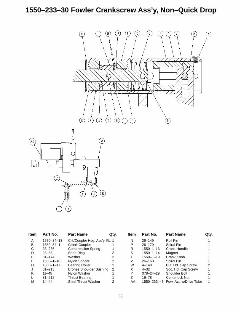
1550–233–30 Fowler Crankscrew Ass’y, Non–Quick Drop
68
Item Part No. Part Name Qty. Item Part No. Part Name Qty.
A 1550–34–13 Crk/Coupler Hsg. Ass’y, Rt. 1 N 26–149 Roll Pin 1B 1550–34–1 Crank Coupler 1 P 26–179 Spiral Pin 1C 38–286 Compression Spring 1 R 1550–1–16 Crank Handle 1D 28–88 Snap Ring 2 S 1550–1–14 Magnet 1E 81–174 Washer 2 T 1550–1–19 Crank Knob 1F 1550–1–18 Nylon Spacer 2 V 26–168 Spiral Pin 1H 1550–1–17 Bearing Collar 1 W 4–148 But. Hd. Cap Screw 2J 81–213 Bronze Shoulder Bushing 2 X 4–32 Soc. Hd. Cap Screw 1K 11–45 Nylon Washer 1 Y 378–24–29 Shoulder Bolt 1L 81–212 Thrust Bearing 1 Z 16–78 Centerlock Nut 1M 14–44 Steel Thrust Washer 2 AA 1550–233–45 Fow. Act. w/Drive Tube 1

1550–234–5 Gatch Crankscrew Ass’y, Non–Quick Drop
69
Item Part No. Part Name Qty. Item Part No. Part Name Qty.A 1550–34–14 Crk/Coupler Hsg. Ass’y, Lt. 1 N 26–149 Roll Pin 1B 1550–34–1 Crank Coupler 1 P 26–179 Spiral Pin 1C 38–286 Compression Spring 1 R 1550–1–16 Crank Handle 1D 28–88 Snap Ring 2 S 1550–1–14 Magnet 1E 81–174 Washer 2 T 1550–1–19 Crank Knob 1F 1550–1–18 Nylon Spacer 2 V 26–168 Spiral Pin 1H 1550–1–17 Bearing Collar 1 W 4–148 But. Hd. Cap Screw 2J 81–213 Bronze Shoulder Bushing 2 X 4–32 Soc. Hd. Cap Screw 1K 11–45 Nylon Washer 1 Y 378–24–29 Shoulder Bolt 1L 81–212 Thrust Bearing 1 Z 16–78 Centerlock Nut 1M 14–44 Steel Thrust Washer 2 AA 1550–234–25 Gat. Act. w/Drive Tube 1

1550–37–10 Qu
ick Dro
p A
ssemb
ly, Fo
wler O
nly
70
p/n 1550–34–20(Ref.)
1510–234–27Midsection Skin(Ref.)

1550–37–10 Quick Drop Assembly, Fowler Only
71
Item Part No. Part Name Qty.A 1550–33–28 Drive Bar Weldment 1B 1550–33–14 Fowler Crkscr. Detent Ass’y 1C 1550–33–25 Quick Drop Brkt. Ass’y, Rt. 1D 1550–33–26 Quick Drop Brkt. Ass’y, Lt. 1E 1550–33–19 Release Arm Weldment 1F 1550–33–20 Handle Guard 2G 1550–33–36 Release Label, Rt. 1H 1550–33–37 Release Label, Lt. 1J 1550–37–15 Fow. Emer. Drop Label, Lt. 1K 1550–37–16 Fow. Emer. Drop Label, Rt. 1L 1550–33–11 Spring/Cable Pin 1M 1550–33–18 Cable Retainer 1N 1550–33–16 Cable Return Arm 1P 1550–33–29 Drive Tube Stop 2R 1550–33–8 Quick Drop Handle Grip 2S 1550–33–9 Fowler/Gatch Release Cable 1T 16–35 Nylock Nut 1V 14–21 Nylon Washer 3W 1550–31–2 Threaded End Fitting 2X 1550–31–1 Fowler Gas Cylinder 1Y (page 66) Fowler Crankscrew Ass’y 1Z (page 69) Gatch Crankscrew Ass’y 1AA 1550–90–23 Fow. Quick Drop Reset Label 1AB 946–1–65 Gatch Symbol Label 1AC 4–5 Soc. Hd. Cap Screw 1AD 4–219 Soc. Hd. Cap Screw 2AE 16–47 Nylock Nut 1AF 21–8 Set Screw 2AG 38–285 Extension Spring 1AH 38–284 Extension Spring 2AJ 11–2 Washer 2AK 14–55 Washer 2AL 28–114 Retaining Ring 2AM 16–28 Nylock Nut 4AN 14–20 Washer 2AP 37–95 End Cap 1AR 3–47 Hex Hd. Cap Screw 4AS 25–79 Pop Rivet 8AT 1550–34–22 Cable Guide 1AV 59–76 Cable Tie 1AW 25–50 Pop Rivet 2AX 16–11 Flexlock Nut 1AY 3–68 Hex Hd. Cap Screw 1AZ 4–105 Hex Hd. Cap Screw 1
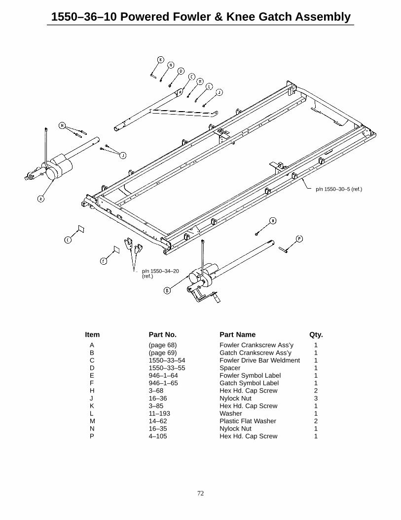
1550–36–10 Powered Fowler & Knee Gatch Assembly
72
p/n 1550–30–5 (ref.)
p/n 1550–34–20(ref.)
Item Part No. Part Name Qty.A (page 68) Fowler Crankscrew Ass’y 1B (page 69) Gatch Crankscrew Ass’y 1C 1550–33–54 Fowler Drive Bar Weldment 1D 1550–33–55 Spacer 1E 946–1–64 Fowler Symbol Label 1F 946–1–65 Gatch Symbol Label 1H 3–68 Hex Hd. Cap Screw 2J 16–36 Nylock Nut 3K 3–85 Hex Hd. Cap Screw 1L 11–193 Washer 1M 14–62 Plastic Flat Washer 2N 16–35 Nylock Nut 1P 4–105 Hex Hd. Cap Screw 1

1010–1–30 Push Handle Assembly
73
Item Part Name Part No. Qty.A 1010–254–18 Sleeve Assembly 1B 1010–254–24 Stop Link 1C 26–10 Roll Pin 1D 1010–254–23 Link Support 1
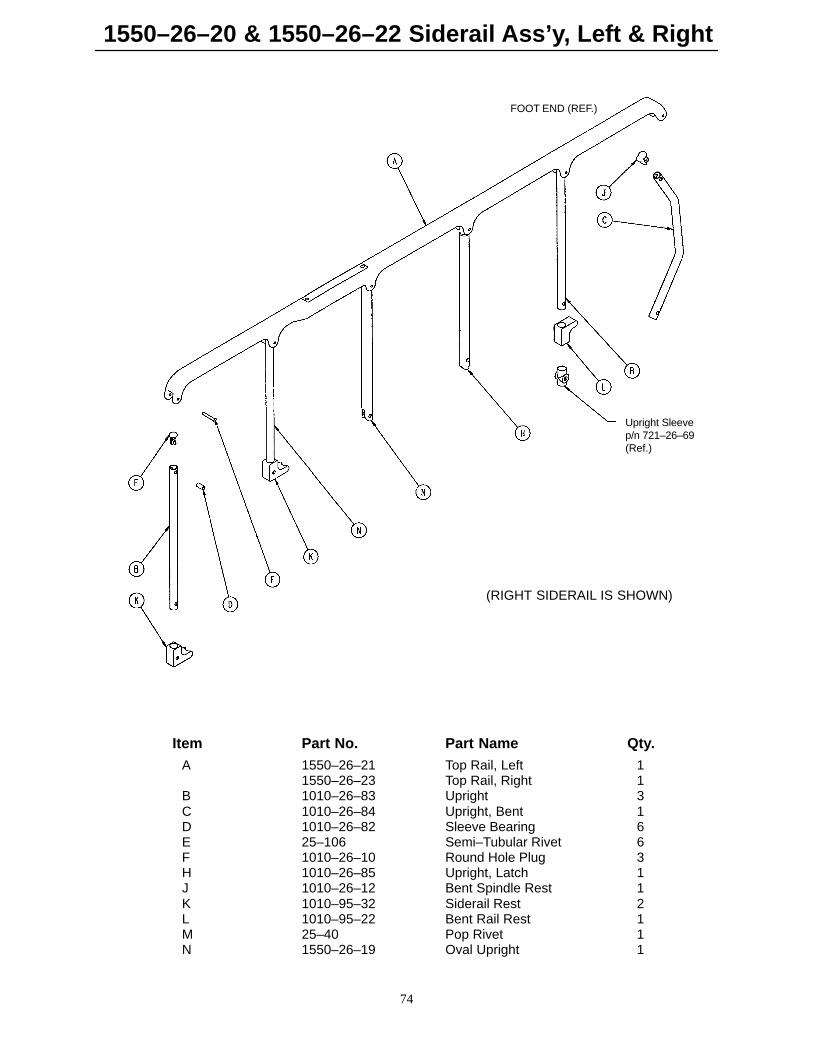
1550–26–20 & 1550–26–22 Siderail Ass’y, Left & Right
74
(RIGHT SIDERAIL IS SHOWN)
Upright Sleevep/n 721–26–69(Ref.)
FOOT END (REF.)
Item Part No. Part Name Qty.A 1550–26–21 Top Rail, Left 1
1550–26–23 Top Rail, Right 1B 1010–26–83 Upright 3C 1010–26–84 Upright, Bent 1D 1010–26–82 Sleeve Bearing 6E 25–106 Semi–Tubular Rivet 6F 1010–26–10 Round Hole Plug 3H 1010–26–85 Upright, Latch 1J 1010–26–12 Bent Spindle Rest 1K 1010–95–32 Siderail Rest 2L 1010–95–22 Bent Rail Rest 1M 25–40 Pop Rivet 1N 1550–26–19 Oval Upright 1
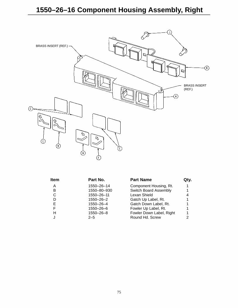
1550–26–16 Component Housing Assembly, Right
75
BRASS INSERT (REF.)
BRASS INSERT(REF.)
Item Part No. Part Name Qty.A 1550–26–14 Component Housing, Rt. 1B 1550–80–930 Switch Board Assembly 1C 1550–26–11 Lexan Shield 4D 1550–26–2 Gatch Up Label, Rt. 1E 1550–26–4 Gatch Down Label, Rt. 1F 1550–26–6 Fowler Up Label, Rt. 1H 1550–26–8 Fowler Down Label, Right 1J 2–5 Round Hd. Screw 2
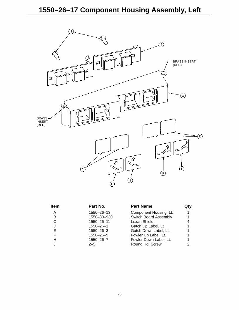
1550–26–17 Component Housing Assembly, Left
76
BRASSINSERT(REF.)
BRASS INSERT(REF.)
Item Part No. Part Name Qty.A 1550–26–13 Component Housing, Lt. 1B 1550–80–930 Switch Board Assembly 1C 1550–26–11 Lexan Shield 4D 1550–26–1 Gatch Up Label, Lt. 1E 1550–26–3 Gatch Down Label, Lt. 1F 1550–26–5 Fowler Up Label, Lt. 1H 1550–26–7 Fowler Down Label, Lt. 1J 2–5 Round Hd. Screw 2

DH 12/93 1550–90–22 REV__
6300 Sprinkle Road, Kalamazoo, MI 49001–9799 (800) 327–0770