synchroteq plusdatasheet stp030000 sp - border states · synchroteq plusdatasheet ... web browser...
TRANSCRIPT

STP030000-SP-en
SynchroTeq PlusDatasheet 2014-06-06
©2014 Vizimax Inc. All rights reserved. 1
SYNCHROTEQ PLUS
DESCRIPTION
The SynchroTeq™ Plus is the most advanced Point on Wave controllers – Controlled Switching Device – CSD - available on the market for medium to high-voltage Independent Pole Operated (IPO) and gang-operated circuit breakers (C/Bs). The SynchroTeq Plus not only controls C/B switching; it also monitors and reports C/B performance problems and alarms.
Using patented operating algorithms, the SynchroTeq Plus unit automatically adjusts C/B operations according to the supply voltage, air temperature, pressure of the drive mechanism and so on. In addition, the unit intelligently adjusts the next operation based on calculations from previous C/B performance.
SynchroTeq Plus supports different types of applications including:
Shunt reactors Capacitor banks while taking into account residual charge (fully charged, partially
discharged and completely discharged) Transmission lines Power transformers while taking into account the residual flux
Also, it can control different live tank/dead tank C/B technologies using hydraulic, pneumatic, spring or motor drive mechanisms.
VIZIMAX SynchroTeq™ products is a manufacturer agnostic solution and has been successfully used on modern and legacy C/B models from different manufacturers such as ABB, Siemens, Alstom, BHEL, and CG. It can be installed on brand new or existing C/Bs.
The SynchroTeq Plus can be controlled locally or remotely. The unit includes a graphical web operating interface and SynchroTeq Configuration Suite™ configuration and data analysis software designed for the MS Windows™ environment.
STP030000-SP-en
SynchroTeq PlusDatasheet 2014-06-06
©2014 Vizimax Inc. All rights reserved. 2
BENEFITS
The benefits of installing a SynchroTeq Plus controller are the following:
Mitigate disturbances, providing utilities, independent power producers (IPPs) and industrial customers with better waveforms and more reliable transmission networks.
Suitable for new or existing HV equipment, allowing you to make the most of your previous investments.
Manufacturer-agnostic solution, compatible with any brand of C/B. Complies with all substation protocols including DNP3, IEC 61850, IEC 60870 and
Modbus using the optional SynchroTeq communication module. Eliminates the need for pre-insertion resistors, which are a major cause of C/B
failure. Modular and expandable platform can be sized to fit any C/B switching application,
with dedicated hardware modules and custom configuration to serve shunt capacitor banks, shunt reactors, power transformers (3-phase and single phase) and uncompensated transmission lines, among others.
Residual flux management modules produce seamless power transformer energization, dramatically reducing the possibility of inrush current. The result? Guaranteed availability across your entire infrastructure, at all times.
CONTROLLED SWITCHING PRINCIPLES
The goal of the SynchroTeq Plus unit is to perform the controlled switching of circuit breaker for opening and/or closing operations. By optimizing the switching of each circuit breaker pole individually, inrush current and voltage transients are virtually eliminated, thus improving grid power quality.
When the SynchroTeq MV receives a CLOSE command, it waits for the first zero-crossing of the source voltage for synchronization of the C/B mechanical operation. It waits for a synchronization delay to send a controlled CLOSE command to each C/B pole at a very precise point on the wave for switching to occur. The OPEN operation is the same as that for CLOSE operation except that a current or a voltage zero-crossing can be used as the reference signal to control the C/B contacts arcing and avoid re-ignition.
The computed time delay is measured from the reference zero-crossing and, using adaptive control, adjusts to account for environmental factors, idle time, and other measurements and variations in the C/B characteristics of each phase.

STP030000-SP-en
SynchroTeq PlusDatasheet 2014-06-06
©2014 Vizimax Inc. All rights reserved. 3
FEATURES
C/B OPERATION TIMING PREDICTION
Using patented operating algorithms, SynchroTeq Plus automatically adjusts C/B operation timing based on measured operating variables, including C/B control voltage, ambient temperature and, for each pole, the pressure of the insulating gas or the drive mechanism. In addition, SynchroTeq Plus intelligently adjusts the next operation based on the elapsed time since the last operation (idle time compensation) and the past history of the C/B timing performance (adaptive control).
EVENTS AND WAVEFORM RECORDING
At each switching operation, SynchroTeq Plus records current and voltage waveforms including the C/B interface signals (52a/52b/Trip/Close/inputs/commands) over a period of 1250 ms (250 ms pre-trigger). These waveforms are part of the sequence of events list which includes the alarms and the operations performed on the unit (for example, alarm reset, in/out of service). Each event includes the SynchroTeq Plus’s complete status and operating environment to allow for detailed analysis. The SynchroTeq Plus has a memory capacity of 2000 events, including the waveforms.
WEB OPERATION INTERFACE
The current status, alarms, readings values and the event list can be displayed on any PC using a Web browser such as Internet Explorer™ or Firefox™. The SynchroTeq Plus Web interface is secured (https://) and access is only granted to authenticated users. This interface provides information about the current status or the status of the unit when an event occurred.
The event details interface is organized into five different views: Unit status, alarms, calculated values for opening, calculated values for closing and measured values. COMTRADE compatible waveforms can be downloaded on request from the Web interface.
COMMUNICATIONS AND HARDWARE OPTIONS
SynchroTeq Plus is equipped with two Ethernet ports for direct connection to a maintenance PC (front panel) or a LAN (back panel), which provides access to the unit. The following options are also offered at extra cost:
Additional Ethernet communication plug-In (fiber optic and/or copper) for remote data analysis and maintenance
Integrated bypass modules (STP 030302) that allows the C/B to be switched when the controlled switching functions are not available (unit unpowered, defective or out of service)
A dual supply SPSBO (STP030303) option can be added to the unit to have the trip/close circuits powered from different supplies.

STP030000-SP-en
SynchroTeq PlusDatasheet 2014-06-06
©2014 Vizimax Inc. All rights reserved. 4
RESIDUAL FLUX MANAGEMENT OPTION
SynchroTeq Plus offers additional three phase voltage measurement required for Power Transformer application algorithm to calculate residual Flux (option STP 030101 or STP 030103). The extra analog inputs are used to calculate the residual flux in each phase when a power transformer is de-energized. SynchroTeq Plus uses these residual flux calculations to optimize CLOSE operation timing, resulting in a drastic reduction or in some cases the complete elimination of the inrush current normally resulting from uncontrolled energizing of the power transformer.
ENCLOSURE AND CABLING
The SynchroTeq Plus cabling is done from the back using screw type removable terminal blocks. AC current connections are made on shorting plugs to prevent CT damage in case a connector is accidentally removed. SynchroTeq Plus is available as a standard Rackmount (RM) enclosure to be installed in the control building. It is also available as a Standalone (SA) unit which can be installed in the C/B control enclosure in the switchyard.
FRONT PANEL OR REMOTE CONTROL
SynchroTeq Plus can be controlled locally from the front panel or remotely with the Web operation interface or by substation protocols using the SynchroTeq Communication Module (RWK 000016).
The SynchroTeq Communication Module allows device to communicate with or operate SynchroTeq Plus using major substation communication protocols including DNP3, Modbus, IEC 60870‐5‐101 & ‐104 and IEC 61850 protocols on Ethernet Copper or FO links and is configured using a XML customization file.
SOFTWARE
SynchroTeq Plus system includes Windows-based SynchroTeq Configuration Suite™ software comprising the SynchroTeq Configurator and the Event Analyzer.
The SynchroTeq Configurator is used to customize the operation of the SynchroTeq Plus and its Web interface using system and application configuration files. It supports both offline and online modes of operation and provides features to exchange these configuration files with the SynchroTeq Plus unit. Typically, the configuration files are designed and managed offline on a maintenance PC and are uploaded to the SynchroTeq Plus as part of the system commissioning.
The Event Analyzer is a COMTRADE compatible enhanced waveform viewer that displays the waveforms and the C/B operation simultaneously

STP030000-SP-en
SynchroTeq PlusDatasheet 2014-06-06
©2014 Vizimax Inc. All rights reserved. 5
MOUNTING
DIMENSIONS
Specifications Value
Width 444 mm/17.5 inch for standard; 483 mm/19 inch for Rackmount installation
Height 4 UM (modular units: 177 mm/7 inch)
Depth 299 mm (12 inch)
Weight 7.5 kg (16.5 lbs.) with optional Residual flux and Bypass options
NOTES: SA version should be installed in a water protected shelter together with the C/B. The SA option provides conformal coating of the electronic circuit boards plus an additional environmental protective cover. For RM installation, the mounting ears can be installed in the front of the unit, but they can be moved to the back or bottom of the unit for panel mount installations.
FIGURE 1 SynchroTeq Plus rackmount dimensions
Leave at least 101.6 mm (4 in) clearance at the back of the unit for the cable connections. Leave at least 44,45 mm (1U, 1.75 in) on the top for heat

STP030000-SP-en
SynchroTeq PlusDatasheet 2014-06-06
©2014 Vizimax Inc. All rights reserved. 6
FIGURE 2 SynchroTeq Plus SA dimensions

STP030000-SP-en
SynchroTeq PlusDatasheet 2014-06-06
©2014 Vizimax Inc. All rights reserved. 7
SYNCHROTEQ PLUS CHARACTERISTICS
CERTIFICATION
COMPLIANCE
Characteristics Standards reference
Value
Operating temperature IEC 68-2-1 and IEC 68-2-2
-40 to +85 ºC *
Relative humidity (R.H.) IEC 68-2-30 < 95 % without condensation
Maximum Altitude MEAS CAT III < 2000 m
Mechanical resistance to vibrations
Performance IEC 60255-21-1 Class 2
Endurance IEC 60255-21-1 Class 1
Dielectric withstand
AC Inputs and I/Os IEC 60255-5 2200 V ac, 1 sec
Communication IEC 60255-5 1650 V ac, 1 sec
Impulse voltage withstand IEC 60255-5 5 kV
Electrostatic discharge (ESD)
Air discharge IEC 61000-4-2 15 kV
Direct contact discharge IEC 61000-4-2 8 kV
Damped Oscillatory Wave (1 MHz burst)
Common mode IEC 60255-22-1 2.5 kV
Differential mode 1.0 kV
Fast transients (bursts) IEC 60255-22-4 Level 4
RF Immunity Modulated IEC 61000-4-3 10 V/m, from 80 MHz to 1 GHz
Non-modulated 10 V/m, from 20 MHz to 80 MHz
Conducted disturbance immunity IEC 61000-4-6 150 KHz to 80 MHz
RF emissions CISPR 22 Class A
Safety IEC 61010-1 :2001
Equipment for measurement, control, and laboratory use
Surge IEC 61000-4-5 Level 4
*See Temperature Derating table
STP030000-SP-en
SynchroTeq PlusDatasheet 2014-06-06
©2014 Vizimax Inc. All rights reserved. 8
CATEGORIES
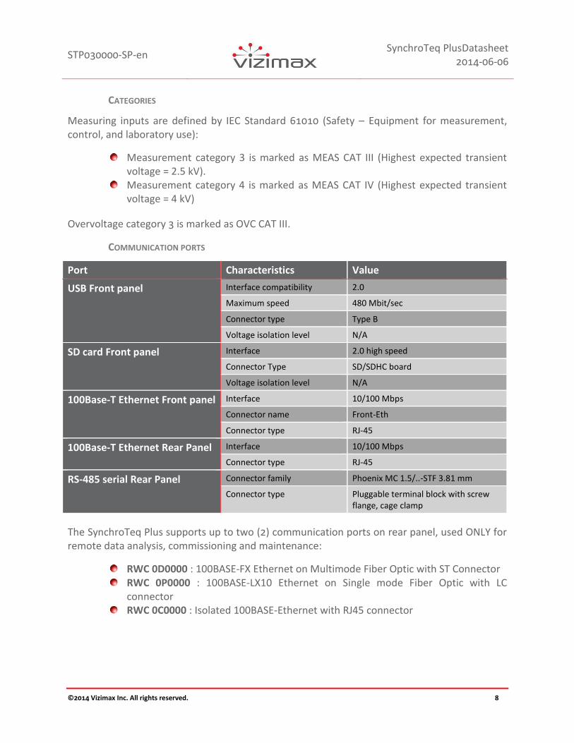
Measuring inputs are defined by IEC Standard 61010 (Safety – Equipment for measurement, control, and laboratory use):
Measurement category 3 is marked as MEAS CAT III (Highest expected transient voltage = 2.5 kV).
Measurement category 4 is marked as MEAS CAT IV (Highest expected transient voltage = 4 kV)
Overvoltage category 3 is marked as OVC CAT III.
COMMUNICATION PORTS
Port Characteristics Value
USB Front panel Interface compatibility 2.0
Maximum speed 480 Mbit/sec
Connector type Type B
Voltage isolation level N/A
SD card Front panel Interface 2.0 high speed
Connector Type SD/SDHC board
Voltage isolation level N/A
100Base-T Ethernet Front panel Interface 10/100 Mbps
Connector name Front-Eth
Connector type RJ-45
100Base-T Ethernet Rear Panel Interface 10/100 Mbps
Connector type RJ-45
RS-485 serial Rear Panel Connector family Phoenix MC 1.5/..-STF 3.81 mm
Connector type Pluggable terminal block with screw flange, cage clamp
The SynchroTeq Plus supports up to two (2) communication ports on rear panel, used ONLY for remote data analysis, commissioning and maintenance:
RWC 0D0000 : 100BASE‐FX Ethernet on Multimode Fiber Optic with ST Connector RWC 0P0000 : 100BASE‐LX10 Ethernet on Single mode Fiber Optic with LC
connector RWC 0C0000 : Isolated 100BASE‐Ethernet with RJ45 connector

STP030000-SP-en
SynchroTeq PlusDatasheet 2014-06-06
©2014 Vizimax Inc. All rights reserved. 9
TEMPERATURE DERATING
Specifications Standards Value
Temperature range Operating temperature IEC 61010-1 -40 to +55 ºC (still air)
Tested operating temperature
IEC 68-2-2 -50 to +75 ºC (natural convection)
Storage temperature -50 to +85 ºC
Temperature testing Cold IEC 68-2-1 -40 C
Dry Heat IEC 68-2-2 55 C (16 hours)
Damp Heat cyclic IEC 68-2-30 40 C at 93 % R.H. (96 hours)
CIRCUIT BREAKER COILS COMMAND OUTPUTS
The SynchroTeq Plus SPSBO module drives the circuit breaker (C/B) coils of each phase of the transformer and has the following characteristics:
Characteristics Value
Number of outputs 6
Output driver technology Solid State, Select Before Operate (SBO)
Rated voltage 48 Vdc, 110 Vdc, 125 Vdc, 220-250 Vdc
Overvoltage category OVC CAT III
DC rated continuous current (tmax= 300 s) 5 A
Maximum making current (tmax=5 ms) 35 A
Maximum breaking current (L/R=0 ms) 20 A
Maximum breaking current when (L/R=40 ms) 20 A
Over current supervision 45 A
Maximum output leakage current <1 mA
Output activation time 10 ms to 100 ms (Programmable increments of 10 ms)
100 ms to 1000 ms (Programmable increments of 100 ms)
C/B coil supervision 3 mA
NOTES: The dual supply SPSBO (STP030303) option can be added to the unit allowing the separation of the OPEN and CLOSE circuit breaker commands on two different isolated power supply using two separate modules (SPSBO Open, and SPSBO Close). The dual supply SPSBO option (STP030303) cannot be used with the Bypass module option (STP030302) since both modules are installed in the same slot.
STP030000-SP-en
SynchroTeq PlusDatasheet 2014-06-06
©2014 Vizimax Inc. All rights reserved. 10
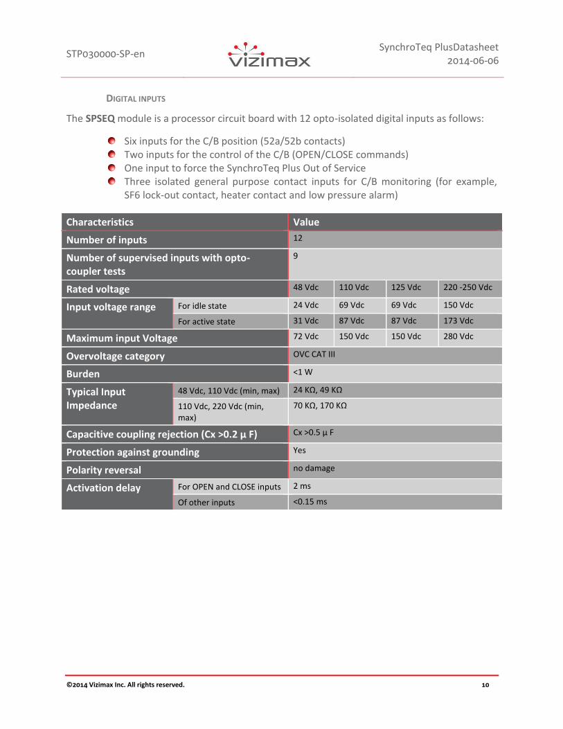
DIGITAL INPUTS
The SPSEQ module is a processor circuit board with 12 opto-isolated digital inputs as follows:
Six inputs for the C/B position (52a/52b contacts) Two inputs for the control of the C/B (OPEN/CLOSE commands) One input to force the SynchroTeq Plus Out of Service Three isolated general purpose contact inputs for C/B monitoring (for example,
SF6 lock-out contact, heater contact and low pressure alarm)
Characteristics Value
Number of inputs 12
Number of supervised inputs with opto-coupler tests
9
Rated voltage 48 Vdc 110 Vdc 125 Vdc 220 -250 Vdc
Input voltage range For idle state 24 Vdc 69 Vdc 69 Vdc 150 Vdc
For active state 31 Vdc 87 Vdc 87 Vdc 173 Vdc
Maximum input Voltage 72 Vdc 150 Vdc 150 Vdc 280 Vdc
Overvoltage category OVC CAT III
Burden <1 W
Typical Input Impedance
48 Vdc, 110 Vdc (min, max) 24 KΩ, 49 KΩ
110 Vdc, 220 Vdc (min, max)
70 KΩ, 170 KΩ
Capacitive coupling rejection (Cx >0.2 µ F) Cx >0.5 µ F
Protection against grounding Yes
Polarity reversal no damage
Activation delay For OPEN and CLOSE inputs 2 ms
Of other inputs <0.15 ms
STP030000-SP-en
SynchroTeq PlusDatasheet 2014-06-06
©2014 Vizimax Inc. All rights reserved. 11
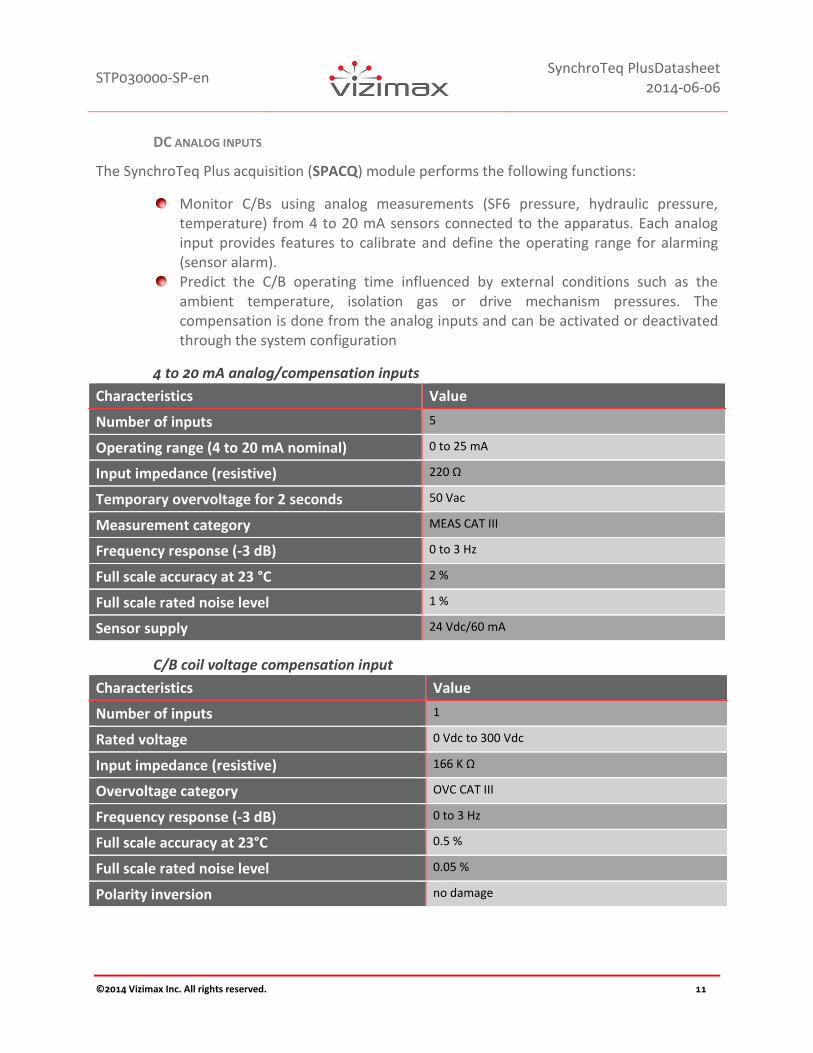
DC ANALOG INPUTS
The SynchroTeq Plus acquisition (SPACQ) module performs the following functions:
Monitor C/Bs using analog measurements (SF6 pressure, hydraulic pressure, temperature) from 4 to 20 mA sensors connected to the apparatus. Each analog input provides features to calibrate and define the operating range for alarming (sensor alarm).
Predict the C/B operating time influenced by external conditions such as the ambient temperature, isolation gas or drive mechanism pressures. The compensation is done from the analog inputs and can be activated or deactivated through the system configuration
4 to 20 mA analog/compensation inputs
Characteristics Value
Number of inputs 5
Operating range (4 to 20 mA nominal) 0 to 25 mA
Input impedance (resistive) 220 Ω
Temporary overvoltage for 2 seconds 50 Vac
Measurement category MEAS CAT III
Frequency response (-3 dB) 0 to 3 Hz
Full scale accuracy at 23 °C 2 %
Full scale rated noise level 1 %
Sensor supply 24 Vdc/60 mA
C/B coil voltage compensation input
Characteristics Value
Number of inputs 1
Rated voltage 0 Vdc to 300 Vdc
Input impedance (resistive) 166 K Ω
Overvoltage category OVC CAT III
Frequency response (-3 dB) 0 to 3 Hz
Full scale accuracy at 23°C 0.5 %
Full scale rated noise level 0.05 %
Polarity inversion no damage

STP030000-SP-en
SynchroTeq PlusDatasheet 2014-06-06
©2014 Vizimax Inc. All rights reserved. 12
SynchroTeq Plus internal temperature monitoring
Characteristics Value
Number of sensors 1
Operating range -55 °C to +85 °C
Frequency response (-3 dB) 0 to 3 Hz
Full scale accuracy 1 %
Full scale rated noise level 0.5 %

STP030000-SP-en
SynchroTeq PlusDatasheet 2014-06-06
©2014 Vizimax Inc. All rights reserved. 13
AC MEASUREMENTS INPUTS
The SynchroTeq Plus SPCTPT module inputs are used to measure the C/B current using current transformers (CTs), and the source (line or bus) voltage using potential transformers (PTs).
CT inputs
Characteristics Value
Number of inputs 3
Connector type Auto-shorting pluggable connector, screw clamp
Current Rated current 1 A or 5 A
Saturation current 2 x In
Maximum current for 1 second 20 x In
Measurement category MEAS CAT III
Burden At rated current In = 1 A/5 A < 0.1 VA/1 VA
Asymmetrical current During 100 ms 100 %
Reading after 100 ms 80 %
Nominal frequency 50 Hz or 60 Hz
Bandwidth (-3 dB) 0.5 Hz to 4 KHz
Sampling frequency 10,000/s
Conversion resolution 16 bit
Full scale Accuracy at 23 °C 0.3 %
Rated noise level 0.15 %
Zero crossing detection Range (frequency) 10 to 70 Hz
Range (current) 5 % to 200 % In
Accuracy 10 µs
Insensitivity to harmonic contents Up to 7 % In for 2nd to 10th harmonics
Crosstalk isolation between channels >76 dB

STP030000-SP-en
SynchroTeq PlusDatasheet 2014-06-06
©2014 Vizimax Inc. All rights reserved. 14
PT inputs
Characteristics Value
Number of inputs 3
Rated voltage 100 Vac, 110 Vac, 120 Vac, 100/3 Vac, 110/3 Vac, 120/3 Vac
Thermal capacity (1 minute) 167 Vac
Measurement category MEAS CAT III
Burden < 1 VA
Nominal frequency 50 Hz or 60 Hz
Bandwidth (-3 dB) 0.5 Hz to 4 KHz
Sampling frequency 10,000/s
Conversion resolution 16 bit
Full scale Accuracy at 23 °C 0.3 %
Rated noise level 0.05 %
Zero crossing detection Range (frequency) 10 to 70 Hz
Range (voltage) 37.5 % to 150 % Vn
Accuracy 10 µs
Insensitivity to harmonic contents Up to 50 % Vn for 2nd to 10th harmonics
Crosstalk isolation between channels >84 dB

STP030000-SP-en
SynchroTeq PlusDatasheet 2014-06-06
©2014 Vizimax Inc. All rights reserved. 15
ADDITIONAL THREE PHASE VOLTAGE MEASUREMENT REQUIRED FOR POWER TRANSFORMER AND
APPLICATION ALGORITHM TO CALCULATE RESIDUAL FLUX
The function boards (SPFLUX module) are used to calculate optimum C/B closing time based on the residual flux in the transformer core after the transformer is de-energized. The residual flux measurement option reduces the inrush current to a magnitude comparable to the magnetization current. SynchroTeq Plus calculates the residual flux from the voltage measurement on the transformer winding using either PTs or from High Voltage bushing sensors installed on the test tap of the bushing.
There are two function boards’ versions:
Acquisition & Residual Flux Calculation Module for PT/CVT with 3 x Analog Inputs (STP 030103): Three (3) additional PT/CVT inputs, plus three (3) 4 to 20 mA inputs. The 4 to 20 mA inputs can be used for two-wire sensor monitoring.
Acquisition & Residual Flux Calculation Module for Power Transformer High Voltage Bushing Sensors (STP 030101): Three (3) additional Power Transformer High Voltage Bushing Sensors inputs suitable for VIZIMAX bushing sensors. The residual flux calculation is made using measurements from the bushing sensors.
Acquisition & Residual Flux Calculation Module for PT/CVT w/ 3 x Analog Inputs (STP 030103)
PT/CVT inputs
Characteristics Value
Number of inputs 3
Input operating range 57 Vac (or 100/3 Vac ) to 120 Vac
Measurement category MEAS CAT III
Thermal capacity (1 minute) 167 Vac
Burden < 3 VA
Rated frequency 50 Hz or 60 Hz
Bandwidth (dc component included) 0 to 3.6 KHz
Sampling frequency 10,000/s
Conversion resolution 16 bit
Full scale accuracy at 23°C 0.5 %
Full scale rated noise level 0.1 %
STP030000-SP-en
SynchroTeq PlusDatasheet 2014-06-06
©2014 Vizimax Inc. All rights reserved. 16
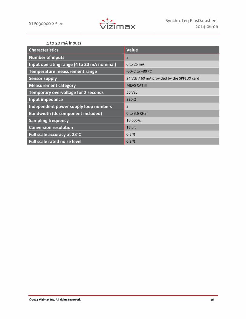
4 to 20 mA inputs
Characteristics Value
Number of inputs 3
Input operating range (4 to 20 mA nominal) 0 to 25 mA
Temperature measurement range -50ºC to +80 ºC
Sensor supply 24 Vdc / 60 mA provided by the SPFLUX card
Measurement category MEAS CAT III
Temporary overvoltage for 2 seconds 50 Vac
Input impedance 220 Ω
Independent power supply loop numbers 3
Bandwidth (dc component included) 0 to 3.6 KHz
Sampling frequency 10,000/s
Conversion resolution 16 bit
Full scale accuracy at 23°C 0.5 %
Full scale rated noise level 0.2 %

STP030000-SP-en
SynchroTeq PlusDatasheet 2014-06-06
©2014 Vizimax Inc. All rights reserved. 17
Acquisition & Residual Flux Calculation Module for PT/CVT w/ 3 x Analog Inputs (STP 030101)
Bushing sensor inputs
Characteristics Value
Number of inputs 3
Voltage operating sensor range 4 to 20 mA
Transformer bushing sensor supply 24 Vdc provided by the SPLUX card
Measurement category MEAS CAT III
Temporary overvoltage for 2 seconds 50 Vac
Input impedance 220 Ω
Independent power supply loop numbers 3
Bandwidth (dc component included) 0 to 3.6 KHz
Sampling frequency 10,000/s
Conversion resolution 16 bit
Full scale accuracy at 23°C 0.5 %
Full scale rated noise level 0.2 %
4 to 20 mA inputs
Characteristics Value
Number of inputs 3
Input operating range (4 to 20 mA nominal) 0 to 25 mA
Temperature measurement range -50ºC to +80 ºC
Sensor supply 24 Vdc / 60 mA provided by the SPLUX card
Measurement category MEAS CAT III
Temporary overvoltage for 2 seconds 50 Vac
Input impedance 220 Ω
Independent power supply loop numbers 3
Bandwidth (dc component included) 0 to 3.6 KHz
Sampling frequency 10,000/s
Conversion resolution 16 bit
Full scale accuracy at 23°C 0.5 %
Full scale rated noise level 0.2 %

STP030000-SP-en
SynchroTeq PlusDatasheet 2014-06-06
©2014 Vizimax Inc. All rights reserved. 18
POWER SUPPLY AND SIGNALING OUTPUTS
The SynchroTeq Plus power supply (SPALIM) module input is set according to the ordering four options are available: 48, 110, 125 or 220-250 Vdc.
Up to 11 electromechanical relays are provided to signal alarm conditions to external devices such as RTUs and annunciators. They can also drive the external bypass logic when the SynchroTeq Plus is defective or out of service.
Characteristics Value
Overvoltage category OVC CAT III
Maximum power consumption 45 W
Polarity inversion No damage
48 Vdc
Characteristics Value
Voltage range 36 Vdc to 72 Vdc
Tolerance to power interruption (IEC 61000-4-29)
Short voltage interruption and voltage variation of 30 %, 60 % and 100 %
100 ms
110 Vdc
Characteristics Value
Voltage range 88 Vdc to 140 Vdc
Tolerance to power interruption (IEC 61000-4-29)
Voltage dip 30% No impact
Short voltage interruption and voltage variation of 60 % and 100 %
100 ms
125 Vdc
Characteristics Value
Voltage range 104 Vdc to 140 Vdc
Tolerance to power interruption (IEC 61000-4-29)
Voltage dip 30% No impact
Short voltage interruption and voltage variation of 60 % and 100 %
100 ms
220-250 Vdc
Characteristics Value
Voltage range 180 Vdc to 280 Vdc
Tolerance to power interruption (IEC 61000-4-29)
Short voltage interruption and voltage variation of 30 %, 60 % and 100 %
100 ms
STP030000-SP-en
SynchroTeq PlusDatasheet 2014-06-06
©2014 Vizimax Inc. All rights reserved. 19
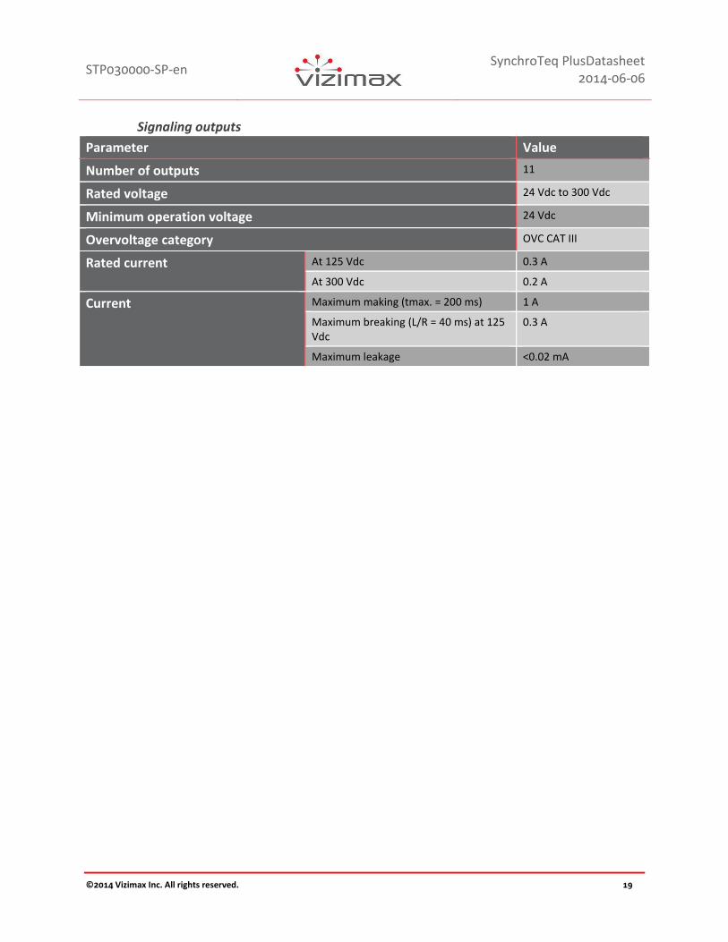
Signaling outputs
Parameter Value
Number of outputs 11
Rated voltage 24 Vdc to 300 Vdc
Minimum operation voltage 24 Vdc
Overvoltage category OVC CAT III
Rated current At 125 Vdc 0.3 A
At 300 Vdc 0.2 A
Current Maximum making (tmax. = 200 ms) 1 A
Maximum breaking (L/R = 40 ms) at 125 Vdc
0.3 A
Maximum leakage <0.02 mA

STP030000-SP-en
SynchroTeq PlusDatasheet 2014-06-06
©2014 Vizimax Inc. All rights reserved. 20
FUNCTIONAL SPECIFICATIONS
WAVEFORM CAPTURE
Parameter Value
Memory capacity Up to 2000 events (waveforms are stored in events)
Capture trigger C/B commands from SynchroTeq Plus (OPEN and CLOSE)
Voltage changes on switched side of C/B (for residual flux calculation on power transformer applications)
Manual trigger using snapshot capture
Sampling rate 167 samples/cycle at 50 Hz and 60 Hz
Recording time 1250 ms with 250 ms pre-trigger
Recorded signals Voltages from PTs on unswitched side of C/B (3)
Load current (3)
Option: Voltages on switched side of C/B (3)
Option: Residual flux calculation (3)
C/B control commands (3 x Open, 3 x close)
C/B position contacts ( 3 x 52a, 3 x 52b)
SynchroTeq Plus command inputs (OPEN and CLOSE)
Phase A synchronization (1 x I, 1 x V)
EVENT MEMORY
Parameter Value
Memory capacity 2000 events, including waveforms when applicable
Recording trigger sources
C/B commands from SynchroTeq Plus
Voltage changes on switched side of C/B (for residual flux calculation on power transformer applications)
Status change (local/remote, in/out of service, cold start, reset, etc.)
Alarms (self-check, sensors, C/B timing problems, C/B interface problem, loss of synchronization signal, etc.)
Configuration changes (new parameters)
Operation failure (rejected commands)
Manual waveform capture
Operation commands to SynchroTeq Plus (alarm reset, operation counters reset, set residual flux, etc.)
Search and display filtering capabilities
The event display can be filtered using one or the combination the following criteria:
By event sequential number
By date
By type (open command, close command, residual flux calculation, sensor problem, etc.)
By alarm type (sensor out of range, excessive inrush current, synchronization loss, etc.)

STP030000-SP-en
SynchroTeq PlusDatasheet 2014-06-06
©2014 Vizimax Inc. All rights reserved. 21
Time tagging display resolution
1 millisecond with time zone management
Time tagging synchronization
NTP time server on Ethernet
IEEE PTP 1588 clock source on Ethernet
Manual synchronization from PC computer
Real time clock autonomy
Approximately 1 week without power (protected with maintenance free super capacitor)
ORDERING INFORMATION
STP 030000 SynchroTeq Plus base unit (Smart Coding to be confirmed) - Compatible w/ either Rackmount or standalone mounting, -40 ºC to 75 ºC (-40 ºF to 165 ºF)
Download the SynchroTeq Plus smart coding on our website: http://www.vizimax.com/support/download
Options:
RWK 000016 Standard SynchroTeq Communication Module for the STU 0x5000 or STP 030000 (2 x Ethernet 100BASE-T + 1 x Ethernet 100BASE-FX multimode + 2 x serial ports) – Protocols DNP3 client and IEC 61850 server + GOOSE – integrated XCBR LN, -40 ºC to 75 ºC (-40 ºF to 165 ºF)
STP 030101 Acquisition & Residual Flux Calculation Module for Bushing Sensors STP 030103 Acquisition & Residual Flux Calculation Module for PT/CVT w/ 3 x
Analog Inputs STP 030302 SHL-1 - DCO Type - Bypass module STP 030303 Dual supply circuit breaker coils command (Dual SPSBO option) STP 030200 Active Junction Box STP 03040X Bushing Sensors for HV Power Transformer
Factory Acceptance Test, Site Acceptance Test, Configuration services and training Module are also available, please inquire.

STP030000-SP-en
SynchroTeq PlusDatasheet 2014-06-06
©2014 Vizimax Inc. All rights reserved. 22
Support contact: [email protected] www.vizimax.com/support
V-FOPR03-011en (2014-05-22)