synchronizer syn 671a - ambac international synchronizer ap-close the generator 's main breaker...
TRANSCRIPT

®
EngineGoverning Systems
SYNCHRONIZERSYN 671A
®
EngineGoverning Systems
®
EngineGoverning Systems
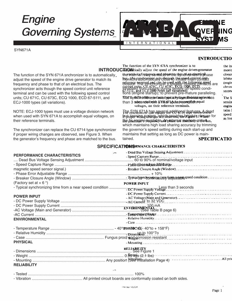
Page 1
ENGINE SYN 671A JGOVERNING
- SYSTEMS section EG 70.8A
INTRODUCTION
The function of the SYN 671A synchronizer is to the internal relay contacts of the synchronizer's phaseautomatically adjust the speed of the engine driven generator monitors automatically close to initiate main contactto match its frequency and phase to that of an electrical closure. The synchronizer's breaker closure contacts are in-bus. The synchronizer acts through the speed control unit hibited from closing during severe off-speed conditionsreference terminal and can be used with the following speed (engine startup), to prevent pre-mature paralleling. The syn-control units: CU 671C, CU 673C, ECQ 1000, ECD chronizer is fast, typically synchronizing in less than 367-5111, and ECJ-1000 types (all variations), seconds from a near speed condition.
NOTE: ECJ-1000 types must use a voltage division network 'The SYN 671A has several additional features. A dead buswhen used with SYN 671A to accomplish equal sensing system, which provides breaker closure for the firstvoltages, on their reference terminals, engine available. An internal memory circuit, which main-
tains high load sharing accuracy by trimming the governor'sThe synchronizer can replace the CU 6714 type synchronizer speed setting during each start-up and maintains that settingif proper wiring changes are observed, see Figure 3. When as long as DC power is maintained.the generator's frequency and phase are matched to the bus,
SPECIFICATIONS
PERFORMANCE CHARACTERISTICS
.... Dead Bus Voltage Sensing Adjustment .............................................. 60 to 90% of nominal/voltage input- Speed Capture Range ...................................................................... _4% (based on 3250 Hz.
magnetic speed sensor signal.)- Phase Error Adjustable Range .............................................................................. + 10%- Breaker Closure Angle (Window) ..................................................... 0 ° + 30 ° continuously adjustable
(Factory set at + 6 °)- Typical synchronizing time from a near speed condition .............................................. Less than 3 seconds
POWER INPUT
- DC Power Supply Voltage ............................................................................ 11 to 32 VDC- DC Power Supply Current ................................................................................. 100 mA- AC Voltage (Main and Generator) ................................................................ (See Table B page 6)- AC Current ....................................................................................... Less than 2 mA
ENVIRONMENTAL
- Temperature Range ............................................................ - 40°to + 70 ° C(- 40°to + 158°F)- Relative Humidity ..................................................................................... up to 100°7o- Case .......................................................................... Fungus proof and corrosion resistant
PHYSICAL
- Dimensions .......................................................................................... See Figure 1- Weight .......................................................................................... 0.95 kgs (2.1 lbs)- Mounting ..................................................................... Any position (See Installation Page 4)
RELIABILITY
- Tested .................................................................................................... 100%- Vibration ................................................ All printed circuit boards are conformally coated on both sides.
Printed in USA Issued December, 1984
Page 1
SYN671A
INTRODUCTION.
SPECIFICATIONS
The function of the SYN 671A snchronizer is to automatically adjust the speed of the engine drive generator to match its frequency and phase to that of an electrical bus. The synchronizer acts though the speed control unit reference terminal and can be used with the following speed control units; CU 671C, CU 673C, ECQ 1000, ECD 67-5111, and ECJ-1000 types (all variations).
NOTE: ECJ-1000 types must use a voltage division network when used with SYN 671A to accomplish equal voltages, on their reference terminals.
The synchronizer can replace the CU 6714 type synchronizer if proper wiring changes are observed, see Figure 3. When the generator’s frequency and phase are matched to the bus.
PERFORMANCE CHARACTERISTICS.... Dead Bus Voltage Sensing Adjustment .............................................. 60 to 90% of nominal/voltage input- Speed Capture Range ...................................................................... _4% (based on 3250 Hz.magnetic speed sensor signal.)- Phase Error Adjustable Range .............................................................................. + 10%- Breaker Closure Angle (Window) ..................................................... 0 ° + 30 ° continuously adjustable(Factory set at + 6 °)- Typical synchronizing time from a near speed condition .............................................. Less than 3 seconds
POWER INPUT- DC Power Supply Voltage ............................................................................ 11 to 32 VDC- DC Power Supply Current ................................................................................. 100 mA-AC Voltage (Main and Generator) ................................................................ (See Table B page 6)-AC Current ....................................................................................... Less than 2 mAENVIRONMENTAL
- Temperature Range ............................................................ - 40°to + 70 ° C(- 40°to + 158°F)- Relative Humidity ..................................................................................... up to 100°7o- Case .......................................................................... Fungus proof and corrosion resistantPHYSICAL
- Dimensions .......................................................................................... See Figure 1- Weight .......................................................................................... 0.95 kgs (2.1 lbs)- Mounting ..................................................................... Any position (See Installation Page 4)RELIABILITY
- Tested .................................................................................................... 100%- Vibration ................................................ All printed circuit boards are conformally coated on both sides.
the internal relay contacts of the synchronizer's phase monitors automatically close to initiate main contact closure. The synchronizer’s breaker closure contacts are inhabited from closing during severe off-speed condi-tions (engine startup), to prevent pre-mature paralleling. The synchronizer is fast, typically synchronizing in less than 3 seconds from a near speed condition.
The SYN 671A has several additional features. A dead bus sensing system, which provides breaker closure for the fis engine available. An internal memory circuit, which maintains high load sharing accuracy by trimming the governor’s speed setting during each start-up and maintains that setting as long as DC power is main-tained.
®
EngineGoverning Systems

®
EngineGoverning Systems
Page 2
ENGINE SYN 671A
GOVERNING JSYSTEMS section EG 70-8A ,:_
234.95 mm9.250" > |
_=_ 104.12 mm 14 104.12 mm _I _ 9.19rnm4.250" _ 4.250" .375 "I I
Q Q QI ;
GAINSTAGlUTY
I I
I [_ :154. mmBREAKER 6.0E3"
CLOSUREANGLE I JI 166.'7mm
I I
DEADBUS [_ _ PHASEERROR SYNCHRONIZED j 6.563"
'Q22,TOCOV. D.C. DEAD
SYN. RLY. SYN. SYN. BUS
MAIN GEN ACT DIG. AN. DIS- BATT. DIS- EN- RELAY DISABLE01 02 01 02 IN OUTOUTABLE r--'-i ABLEABLE _
1 2 3 4 5 6 7 8 j. 9 10 11 12 13 14 15 16
(_ WARNINGHIGHVOLTAGE ,_/
/ * ,,.Oloo6.35 mm .906"
l .250"6.73 mm
.265" DIA.6 MTG.HOLES
Figure 1. SYN 671A synchronizer dimensions
DESCRIPTION
The SYN 671A synchronizer operates by sensing the fre- Dead Bus Feature
quency and phase of the main bus AC signal and comparing
it with the corresponding frequency and phase of the A dead bus automatic breaker closure feature is provided to
generator's AC signal (See Figure 2). The synchronizer ap- close the generator's main breaker on the first generator
plys a DC signal to the speed control unit which increases or available for power generation. Other engines are signaled
decreases the speed setting of the governor in order to bring via a dead bus connection to auto-synchronize to the first
the generator to the same frequency and phase as the mains, generator on line.
The synchronizer is faster than motorized controls and like This exclusive feature automatically closes the generator's
the motorized control retains its setting as long as DC power main circuit breaker when the generator's voltage has reach-
is applied to the speed control unit. ed a given level of the nominal voltage rating (typically
75%). A main signal is available for other engines to syn- /--_
chronize to when the generator circuit breaker closes.
PrintedinUS.A Page 2 IssuedDecember,1984
SYN671A
GAIN
STABILITY
BREAKERCLOSURE ANGLE
DEAD BUS
REFER TO SERVICEPUBLICATION WHEN
INSTALLING OR SERVICINTHIS ENGINE SPEED
CONTROLLING DEVICE
-CAUTION-
SYNCHRONIZEDPHASE ERROR
TYPESERIAL NO.
MADE IN SPRINGFIELD MA USA4 REGISTERED TRADEMARKS
SYNCHRONIZER
1 2 3 4 5 6 7 8 9 10 11 12 13 14 15 1601 02 01 02 IN OUT OUT ABLE
BATT.MAIN GEN ACT DIG. AN.
TO COV.SYN.DIS-
ABLE ABLE
DEADBUS
DISABLE
D.C.SYN.EN-
RLY.DIS-
SYN.RELAY
WARNING HIGH VOLTAGE
Figure 1. CYN 671A synchronizer dimensions
DESCRIPTION
The SYN 671A synchronizer operates by sensing the frequency and phase of the main bus AC signal and comparing it with the correspond-ing frequency and phase of the generator’s AC signal (See figure 2). The synchronizer apply’s a DC signal to the speed control unit which increases or decreases the speed setting of the governor in order to bring the generator to the same frequency and phase in the mains.
The synchronizer is faster than motorized controls and like the motorized control retains its setting as long as DC power is applied to the speed control unit.
Dead Bus Feature
A dead bus automatic breaker closure feature is provided to close the generator’s main breaker on the first generator available for power generation. other engines are signaled via a dead bus conection to auto-synchronize to the first generator on line.
This exclusive feature automatically closes the generato’s mai circuit breaker when the generator’s voltage has reached a given level of the nominal voltage rating (typically 75%). A main signal is available for other engines to synchronize to when the generator circuit breaker closes.
154. mm6.063”
166.7 mm6.563”
6.73 mm.265” DIA.
6 MTG. HOLES
6.35 mm.250”
23.01 mm.906”
9.19mm.375”
234.95 mm9.250”
104.12 mm4.250”
104.12 mm4.250”
®
EngineGoverning Systems

®
EngineGoverning Systems
Page 3
SYN671A
Figure 2. SYN 671A synchronizer functional schematic
If the system is a single engine application to be operated in parallel with the utility, the synchronizer will initiate with the load, or synchro-nize to the utility without extra equipment. With multi engine applica-tions the dead bus sensor signals other units via a dead bus connec-tion (terminal 16) that a particular unit has closed to the mains. The dead bus feature is voided on all other units by the first unit to ground
terminal 16. This simple system automatically selects a master, eliminating an extra speed switch or voltage sensing circuits.
NOTE: The dead bus feature can be voided by manually connecting terminal 15 to terminal 16. In this mode, the relay will close only when it is synchronize to the master.
GENERATORSENSING
3
4
PHASEDETECTOR
GENERATORSENSING
DEADBUS
SENSING
VOLTAGELEVEL
SENSINGADJUSTMENT
PHASEERRORADJUST
INHIBIT
BREAKERCLOSURECIRCUIT
(E.G. STATUSSENSING)
(AC)
(DC)
FROMSPEED
CONTROLUNIT
RESETLOGIC
5
12
7
TOSPEED
CONTROLUNIT
ANALOGOUTPUT
1
2
DYNAMICCONTROLCIRCUIT
GAINSTABILITY
BREAKERCLOSURE
ANGLEADJUSTMENT
6DIGITALMEMORY
& OUTPUT
COMMON
RELAYDRIVER RELAY
N.O.
13
14
DEADBUS
PHASEOUTPUT
-
+
RELAYINHIBIT
POWERSUPPLY
11
9
10
LED
POWERSUPPLY
16 15 8
®
EngineGoverning Systems

®
EngineGoverning Systems
Page 4
ENGINE SYN 671A JGOVERNING
SYSTEMS section EG 70-8A s-,i j'
Memory Output Feature switch, then terminal 12 must be used. Applying the positiveDC voltage supply will commence synchronizer operation.
The SYN 671A synchronizer offers a digital based memory Generally, terminal 5 is used. Terminal 5 senses the speedoutput signal. Terminal 6 provides the digital base memory control unit status (actuator chopping frequency). When aoutput. This signal is continuous, smooth, exhibits high signal is present the synchronizer will commence operationresolution, and commands the speed control unit to change by adjusting the governor's speed setting.its speed setting when generator set synchronizing is re-quired. During synchronizing, this signal is active but, on Synchronizer Resetcompletion of synchronization, the digital signal holds itslast setting, either by manual or automatic methods, as long The synchronizer can be reset automaticaly or from feed-as DC power is applied to the synchronizer. The memory back from the main breaker. After synchronization andoutput signal is held manually by opening connections to r,Jay contact closure occurs the DC output signal (terminalterminal 5 or terminal 12 and automatically, approximately 6) to the speed control unit will hold at its value. The last2 seconds after the relay closes. The result is improved load value is held immediately if terminal 5 or terminal 12 are
disconnected (feedback via auxiliary contacts on main circuitsharing repeatability, even after repeated speed control unitspeed Setting changes to accomplish generator set syn- breaker). This value will be held until power is lost or the
synchronizer is enabled thru terminal 5 or terminal 12. If thechronizing.feedback contacts of the main circuit breaker do not open
The digital based memory output signal is typically selected terminal 5 or terminal 12, then the synchronizer willas the input to the speed control unit. However, utilizing the automatically turn off after 2 seconds. It will thendigital based memory effectively requires the initial setting automatically re-synchronize if the phaseof the speed of all generators to be close to the desired drifts beyond the + 6 o factory set breaker closure angle.
speed setting. The analog output signal (terminal 7) is in continuous opera-Synchronizer Enable Feature tion as long as terminal 5 or terminal 12 are connected to a :-.
voltage supply or the actuator terminal. Opening terminal 5 __j_The synchronizer is commanded to operate once a signal is or terminal 12 will cause the synchronizer to reset to zeroreceived at terminal 5 (AC) or terminal 12 (DC). If the syn- speed change (5 volts). This is exactly the same function aschronizer is to be turned on and off with contacts from a the CU 6714D synchronizer.
INSTALLATION
The SYN 671A synchronizer is rugged enough for mounting The synchronizer is connected to the speed control unit andin the control cabinet or engine mounted enclosure. Care the switch gear per the wiring diagram in Figure 3. The out-should be taken to insure that the synchronizer is not sub- put of the synchronizer is typically connected to the same in-jected to extreme heat, as the life of electronic devices is put on the speed control unit along with the load sharing.always related to heat. If it is expected that water or mist The synchronizer enable automatically activates the syn-will come in contact with the synchronizer, mount it ver- chronizer. This is typically connected to the actuator's cir-tically so the condensation will not accumulate in the syn- cuit or switch gear. Table A lists the terminals for connec-chronizer, tion of the synchronizer enable and memory outputs for
each type of United Technologies Diesel Systems speed con-trol units.
ADJUSTMENTS
Adjustments are provided for performance (gain and stabili- The phase inputs from the generator and the mains must bety), circuit breaker closer angle (window), dead bus voltage from corresponding phases as shown in Figure 3, so Phase 1sensing, and phase error trimming, of generator will synchronize with Phase 1 of main. It is
suggested that a temporary jumper be installed during initialFor line to neutral sensing, Phase 2 (terminals 2 and 4) mustinstallation to simplify adjustments from terminal 10 to ter-
be grounded to terminal 10 and the neutral of the generator minal 11 to prevent breaker closure until the system checksmust be grounded. The dead bus sensing range is F _automatically reduced by 40%. and alignment is completed. , _
Printed in U.S.A. Issued December, 1984Page 4
SYN671A
Memory Output Feature
The SYN 671A synchronizer offers a digital based memory output signal. Terminal 6 provides the digital base memory output. This signal is continuous, smooth, exhibits high resolution, and commands the speed control unit to change its speed setting when generator set synchronizing is required. During synchronizing, this signal is active but, on completion of synchronization, the digital signal holds its last setting, either by manual or automatic methods, as long as DC power is applied to the synchronizer. The memory output signal is held manually by opening connections to terminal 5 or terminal 12 and automatically, approximately 2 seconds after the relay closes. The result is improved load sharing repeatability, even after repeated speed control unit speed setting changes to accom-plish generator set synchronizing.The digital based memory output signal is typically selected as the input to the speed control unit. However utilizing the digital based memory effectively requires the initial setting of the speed of all generators to be closed to the desired speed setting.
Synchronizer Enable Feature
The synchronizer is commanded to operate once a signal is received at terminal 5 (AC) or terminal 12 (DC). If the synchro-nizer is to be turned on and off with contacts from a switch, then terminal 12 must be used.
switch, then terminal 12 must be used. Applying the positive DC voltage supply will commence synchronizer operation. Generally, terminal 5 is used. Terminal 5 senses the speed control unit status (actuator chopping frequency). When a signal is present the synchronizer wil commence operation by adjusting the governor’s speed setting.
Synchronizer Reset
The synchronizer can be reset automaticaly or from feedback from the main breaker. After synchronization and relay contact closure occurs the DC output signal (terminal 6) to the speed control unit will hold at its value. The last value is held immedi-ately if terminal 5 or terminal 12 are disconnected (feedback via auxiliary contacts on main circuit breaker). This value will be held until power is lost or the synchronizer is enabled thru terminal 5 or terminal 12. If the feedback contacts of the main circuit breaker do not open terminal 5 or terminal 12, then the synchronizer will automatically turn off after 2 seconds. It will then automatically re-synchronize if the phase drifts beyond the ± 6º factory set breaker closure angle.
The analog output signal (terminal 7) is in continuous operation as long as terminal 5 or terminal 12 are connected to a voltage supply or the actuator terminal. Opening terminal 5 or terminal 12 will cause the synchronizer to reset to zero speed change (5 volts). This is exactly the same function as the CU 6714D synchronizer.
INSTALLATION
ADJUSTMENTS
The SYN 671A sychronizer is rugged enough for mounting in the control cabinet or engine mounted enclosure. Care should be taken to insure that the synchrnoizer is not subjected to extreme heat, as the life of electric devices is always related to heat. If it is expected that water or mist will come in contact with the synchronizer, mount it vertically so the condensation will not accumulate in the synchronizer.
The synchroizer is connected to the speed control unit and the swich gear per the wiring diagram in Figure 3. The ouput of the synchronizer is typically connected to the same input on the speed control unit along with the load sharing. The synchroniz-er enable automatically activates the synchrnoizer. This is typically connected to the actuator’s circuit or sitch geat. Table A lists the terminals for connectio of the snchronizer enable and memory outputs for each type of United Technologies Diesel Systems speed control unit.
Adjustments are provided for performance (gain and stability), circuit breaker closer angle (window), dead bus voltage sensing, and phase error trimming.
For line to neutral sensing, Phase 2 (terminals 2 and 4) must be grounded to terminal 10 and the neutral of the generator must be grounded. The dead bus sensing range is automati-cally reduced by 40%
The phase inputs from the generator and the mains must be from corresponding phases as sshown in Figure 3, so Phase 1 of generator will synchronize with Phase 1 of main. It is suggested that a temporary jumper be installed during initial installation to simplify adjustments from terminal 10 to terminal 11 to prevent breaker closure until the system checks and alignment is completed.
®
EngineGoverning Systems

®
EngineGoverning Systems
Page 5
SYN671A
GAIN
STABILITY
BREAKERCLOSURE ANGLE
DEAD BUS
REFER TO SERVICEPUBLICATION WHEN
INSTALLING OR SERVICINTHIS ENGINE SPEED
CONTROLLING DEVICE
-CAUTION-
SYNCHRONIZEDPHASE ERROR
TYPESERIAL NO.
MADE IN SPRINGFIELD MA USA4 REGISTERED TRADEMARKS
SYNCHRONIZER
1 2 3 4 5 6 7 8 9 10 11 12 13 14 15 1601 02 01 02 IN OUT OUT ABLE
BATT.MAIN GEN ACT DIG. AN.
TO COV.SYN.DIS-
ABLE ABLE
DEADBUS
DISABLE
D.C.SYN.EN-
RLY.DIS-
SYN.RELAY
DEAD BUSSIGNAL
TEST
S1TO TERMINAL 16 ON
OTHER SYN 671’S
*
TO VOLAGESUPPLY
D.C.SUPPLY
-
+
ENABLE
OUTPUT(TO SPEED
CONTROL UNIT)
*NOTE: Jumper only required if dead bus feature is not to be used.
FIGURE 3. Wiring to SYN 671A synchronizer
®
EngineGoverning Systems
®
EngineGoverning Systems
Page 6
ENGINE SYN 671A iGOVERNING
SYSTEMS section EG 70-8A ,,,"_
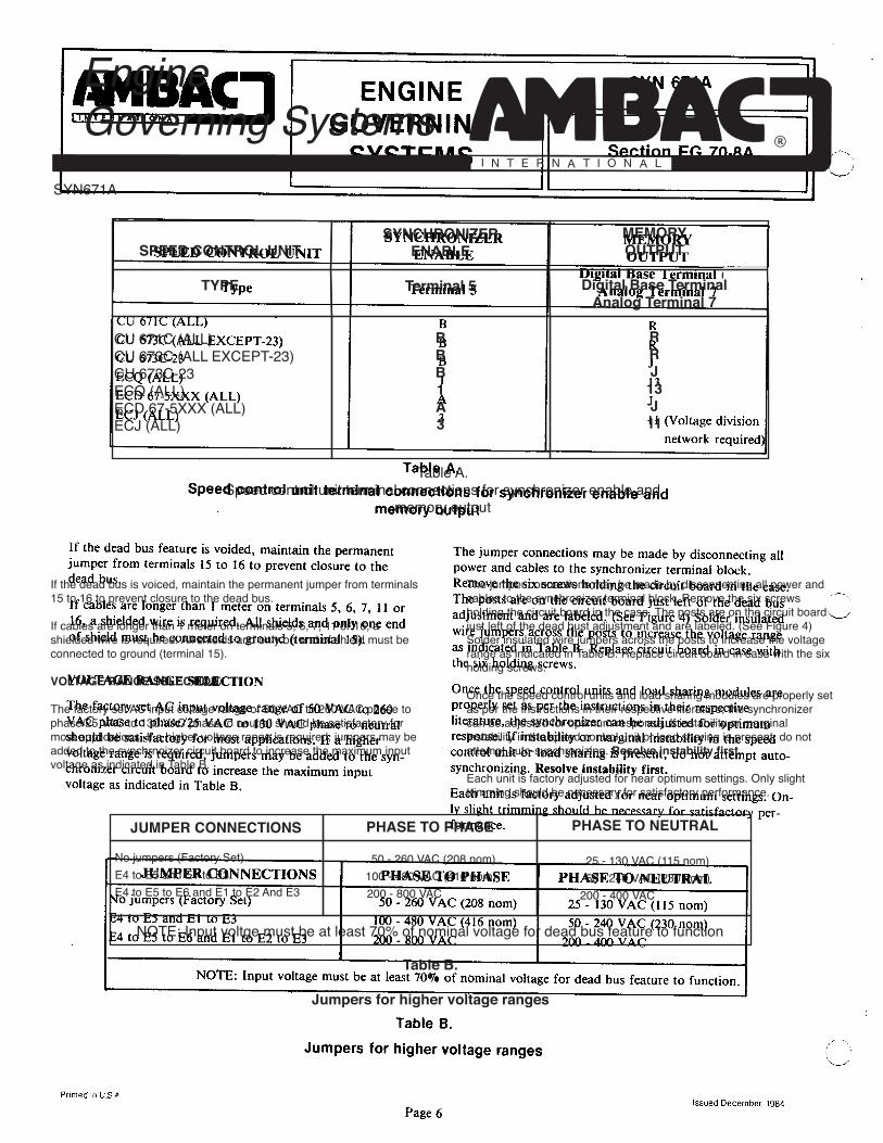
SYNCHRONIZER MEMORYSPEED CONTROL UNIT ENABLE OUTPUT
Digital Base Terminal 6/Type Terminal 5 Analog Terminal 7
CU 671C (ALL) " B R
CU 673C (ALL EXCEPT-23) B RCU 673C-23 B J
ECQ (ALL) l 13ECD 67-5XXX (ALL) A J
ECJ (ALL) 3 I I (Voltage divisionnetwork required)
Table A.
Speed control unit terminal connections for synchronizer enable andmemory output
If the dead bus feature is voided, maintain the permanent The jumper connections may be made by disconnecting alljumper from terminals 15 to 16 to prevent closure to the power and cables to the synchronizer terminal block.dead bus. Remove the six screws holding the circuit board in the case.
The posts are on the circuit board just left of the dead bus ' --"'If cables are longer than 1 meter on terminals 5, 6, 7, 11 or adjustment and are labeled. (See Figure 4) Solder insulated _-J16, a shielded wire is required. All shields and only one end wire jumpers across the posts to increase the voltage rangeof shield must be connected to ground (terminal 15). as indicated in Table B. Replace circuit board in case with
the six holding screws.
VOLTAGE RANGE SELECTION Once the speed control units and load sharing modules are
The factory set AC input voltage range of 50 VAC to 260 properly set as per the instructions in their respectiveVAC phase to phase/25 VAC to 130 VAC phase to neutral literature, the synchronizer can be adjusted for optimumshould be satisfactory for most applications. If a higher response. If instability or marginal instability in the speedvoltage range is required, jumpers may be added to the syn- control unit or load sharing is present, do not attempt auto-chronizer circuit board to increase the maximum input synchronizing. Resolve instability first.
voltage as indicated in Table B. Each unit is factory adjusted for near optimum settings. On-ly slight trimming should be necessary for satisfactory per-formance.
JUMPER CONNECTIONS PHASE TO PHASE PHASE TO NEUTRAL
No jumpers (Factory Set) 50 - 260 VAC (208 nora) 25 - 130 VAC (115 nom)E4 to E5 and El to E3 100 - 480 VAC (416 nom) 50 - 240 VAC (230 nom)E4 to E5 to E6 and El to E2 to E3 200 - 800 VAC _ - 400 VAC
NOTE: Input voltage must be at least 70% of nominal voltage for dead bus feature to function.
TableB.
Jumpersfor highervoltageranges
Prinled 'r_ U,S # Issued Oecember, 1984
Page 6
SYN671A
SYNCHRONIZERENABLE
Terminal 5
BBB1A3
SPEED CONTROL UNIT
TYPE
MEMORYOUTPUT
Digital Base TerminalAnalog Terminal 7
RRJ13J11
CU 671C (ALL)CU 673C (ALL EXCEPT-23)CU 673C-23ECQ (ALL)ECD 67-5XXX (ALL)ECJ (ALL)
Table A.Speed control unit terminal connections for synchronizer enable and
memory output
If the dead bus is voiced, maintain the permanent jumper from terminals 15 to 16 to prevent closure to the dead bus.
If cables are longer than 1 meter on terminals 5, 6, 7, 11 or 16, a shielded wire is required. All shields and only on end of shield must be connected to ground (terminal 15).
VOLTAGE RANGE SELECTION
The factory set AC input coltage range of 50 VAC to 260 VAC phase to phase/25 VAC to 130 VAC phase to neutral should be satisfactory for most applications. If a higher voltage range is required, jumpers may be added to the synchrnoizer circuit board to increase the maximum input voltage as indicated in Table B.
The jumper connections may be made by disconnecting all power and cables to the synchronizer terminal block. Remove the six screws holding the circuit board in the case. The posts are on the circuit board just left of the dead bust adjustment and are labeled. (See Figure 4) Solder insulated wire jumpers across the posts to increase the voltage range as indicated in Table B. Replace circuit board in case with the six holding screws.
Once the speed control units and load sharing modules are properly set as per the instructions in their respective literature, the synchronizer can be adjusted for optimum response. If instability or marginal instability in the speed control unit or load sharing is present, do not attempt auto-synchronizing. Resolve instability first.
Each unit is factory adjusted for near optimum settings. Only slight trimming should be necessary for satisfactory performance.
No jumpers (Factory Set)E4 to E5 and E1 to E3E4 to E5 to E6 and E1 to E2 And E3
JUMPER CONNECTIONS PHASE TO PHASE PHASE TO NEUTRAL
NOTE: Input voltge must be at least 70% of nominal voltage for dead bus feature to function
Table B.
Jumpers for higher voltage ranges
®
EngineGoverning Systems

®
EngineGoverning Systems
Page 7
GAIN
STABILITY
BREAKERCLOSURE ANGLE
REFER TO SERVICEPUBLICATION WHEN
INSTALLING OR SERVICINTHIS ENGINE SPEED
CONTROLLING DEVICE
-CAUTION-
SYNCHRONIZEDPHASE ERROR
TYPESERIAL NO.
MADE IN SPRINGFIELD MA USA4 REGISTERED TRADEMARKS
SYNCHRONIZER
1 2 3 4 5 6 7 8 9 10 11 12 13 14 15 1601 02 01 02 IN OUT OUT ABLE
BATT.MAIN GEN ACT DIG. AN.
TO COV.SYN.DIS-
ABLE ABLE
DEADBUS
DISABLE
D.C.SYN.EN-
RLY.DIS-
SYN.RELAY
E6 E4 E5E2E1E3
Figure 4. Post locations for voltage range selection
Five adjustments are located under the large rubber plug.The adjustments are factory set as follows: Gain Mid Range Stability 60% CW Breaker Closure Angle 6 Degree Window Phase Error Less than 3 Degrees Dead Bus Closure Voltage 160 Volts AC (Line to Line)
Step 1. Close the test switch S1 (relay will not close but LED will light when synchronized.)
2. Call for auto-synchronizing with the switch gear (main bus alive). The unit should send out a DC voltage to the speed control unit to take control. (Voltage can be measured at terminals 6 0r 7). The unit should synchronize to near zero phase.
3. Turn the gain control Cw until instability results. Then back-off slightly CCQ beyod the point where stability returns. Disturb the synchronizer off and on. Not the synchrnoizers characteristics on the synchrnoscope, both the time to scynchrnoize and the time response or
damping (under or over damped). f performance is satisfactory go to step 5.
4. Optimizing the control can be accomplished by adjsting the stability control. If the synchronizing to zero phase error is overdamped as it approaches zero turn the stability slightly CW. CCW adjustment will correct for an underdamped characteristics. Readjust the gain control per step 3.
5. Note the final positio of the synchroscope. If this is other than zero carefuly adjust the phase error control for a zero reading. The LED will light when the unit is synchronized. (The relay will not close until the test switch S1 is opened.)
6. The breaker closure angle is preset to ± 6 degrees. If an wider window is desired, urn the closure control CW. TOo narrow a window will increase synchronizing time. If misadjustment is encountered turn the control to the maximum CCw position. Allow the system to synchronize. Slowly turn the breakosure control SW until the LED lights then continue 30 degrees CW. This will be about a ± 6 degree window.
SYN671A
®
EngineGoverning Systems

®
EngineGoverning Systems
Page 8
SYN671A
STEP TERMINALS NORMAL READING PROBABLE CAUSE OF ABNORMAL READING
1 9 + to 10- Battery Voltage 1) Faulty wiring 2)Low battery
2
3 3 to 4 System voltage AC 1) No generator voltage (generator bus) 2) Faulty wiring
4 5 to 10- 5-20 VDC 1) Actuator full on or off (Actuator signal) 2) Faulty wiring
5 8 to 10- 4.8 ± 0.3 VDC 1) Low; external sync disable or out of frequency range (voltage vs. phase) 2) Erratic (noise on AC lines) 3) High; out of frequency range or defective unit
1 to 2 System voltage AC 1) No bus voltage (main bus) 2) Faulty wiring
6 10- to 11 0 VDC 1) Jumper from terminals 10 to 11 disconnected
7 15 to 16 0 VDC 1) Dead bus jumper terminals 15 to 16 not connected 2) Defective unit
8 7 to 10 3.5 to 6.5 VDC 1) Frequency out of range (typically 5.1 V) 2) Faulty wiring 3) defective unit9 6 to 10- Same as step 8 1) Faulty wiring 2) Defective unit
10 13 to 14 Breaker control voltage 1) Terminal 11 not grounded 2) Relay or contacts damaged, defective unit
TROUBLESHOOTING
7. Calibration of the dead bus feature to other than specified setting is accomplished by temporarily disconnecting the main sensing terminals (1 and 2) and applying an adjustable AC voltage to termainsl 3 and 4 (generator connections temporarily disconnected or output of generator lowered to 70% of rating. Adjust the dead bus adjustment CCW to lower
the relay closure point vs. AC voltage input or CW to raise the trip point.
8. Re-connect main sensing leads, open S1, and replace rubber grommet in cover.
Connect a jumper from terminal 10 to terminal 11 on SYN 671A synchrnozier to disable the breaker closure relay from closing. Also connect a jumper from synchrnozier terminal 5 to actuator terminal B. Start engine in manual with a live bus. The LED on the synchronizer will light when synchronized. If the unit synchronizes as noted on synchroscope, but LED on the
synchronizer does not light, breaker closure angle may be set too low.
If problems still exist, take the following measurements to determine if the unit is at fault with the engine running.
®
EngineGoverning Systems