symmetric 1a power supply - velleman · 2 features low cost universal symmetric power supply just...
TRANSCRIPT

SYMMETRIC 1A POWER SUPPLY
K8042
ILLUSTRATED ASSEMBLY MANUAL H8042IP-1
Low cost universal symmetric
power supply

2
Features low cost universal symmetric power supply just add a suitable transformer and a heatsink ideal for e.g. op-amp applications, amplifiers, ... trimmers can be replaced by potmeters to allow continuous adjustment of output voltage LED output indicators compact size Specifications : positive and negative output adjustable between 1.2 and 24VDC output current: up to 2 x 1A continuous (with suitable heatsink) max. input voltage: 2 x 24VAC very good line and load regulation low ripple short circuit protection thermal protection optional heatsink: HS4003 (for maximum 20W dissipation) dimensions: 78 x 52 x 24mm (3.1" x 2.0" x 0.9")
Features & Specifications

3
Assembly hints
1. Assembly (Skipping this can lead to troubles ! ) Ok, so we have your attention. These hints will help you to make this project successful. Read them carefully. 1.1 Make sure you have the right tools: A good quality soldering iron (25-40W) with a small tip.
Wipe it often on a wet sponge or cloth, to keep it clean; then apply solder to the tip, to give it a wet look. This is called ‘thinning’ and will protect the tip, and enables you to make good connections. When solder rolls off the tip, it needs cleaning.
Thin raisin-core solder. Do not use any flux or grease.
A diagonal cutter to trim excess wires. To avoid injury when cutting excess leads, hold the lead so they cannot fly towards the eyes.
Needle nose pliers, for bending leads, or to hold components in place.
Small blade and Phillips screwdrivers. A basic range is fine.
For some projects, a basic multi-meter is required, or might be handy
1.2 Assembly Hints :
Make sure the skill level matches your experience, to avoid disappointments. Follow the instructions carefully. Read and understand the entire step before you perform each operation. Perform the assembly in the correct order as stated in this manual Position all parts on the PCB (Printed Circuit Board) as shown on the drawings. Values on the circuit diagram are subject to changes. Values in this assembly guide are correct* Use the check-boxes to mark your progress. Please read the included information on safety and customer service
* Typographical inaccuracies excluded. Always look for possible last minute manual updates, indicated as ‘NOTE’ on a separate leaflet.
0.000

4
Assembly hints
1.3 Soldering Hints :
1- Mount the component against the PCB surface and carefully solder the leads
2- Make sure the solder joints are cone-shaped and shiny
3- Trim excess leads as close as possible to the solder joint
REMOVE THEM FROM THE TAPE ONE AT A TIME !
AXIAL COMPONENTS ARE TAPED IN THE CORRECT MOUNTING SEQUENCE !
You will find the colour code for the resistances and the LEDs on our website: http://www.velleman.be/common/service.aspx

5
R1 : 120 (1 - 2 - 1 - B) R2 : 120 (1 - 2 - 1 - B) R3 : 2K2 (2 - 2 - 2 - B) R4 : 2K2 (2 - 2 - 2 - B)
3. Resistors R...
Construction
D1 : 1N4007 D2 : 1N4007 D3 : 1N4007 D4 : 1N4007 D5 : 1N4007 D6 : 1N4007 D7 : 1N4007 D8 : 1N4007 D9 : 1N4007 D10 : 1N4007
2. Diodes. Watch the polarity !
D...CATHODE
J
1. Jump wire
C3 : 100nF (104) C4 : 100nF (104)
4. Capacitors.
C...
RV1 : 2K2 (2K5) RV2 : 2K2 (2K5)
5. Trim potentiometers
SK1 : 2p SK2 : 2p
SK3 : 3p
6. Terminal blocks
LD1 : 3mm Red LD2 : 3mm Red
LD...
CATHODE
23mm0.9"
7. LEDs. Watch the polarity!
10mm
C5 : 10µF C6 : 10µF C7 : 10µF C8 : 10µF
C1 : 1000µF C2 : 1000µF
8. Electrolytic Capacitors. Watch the polarity !
C...
6
Construction
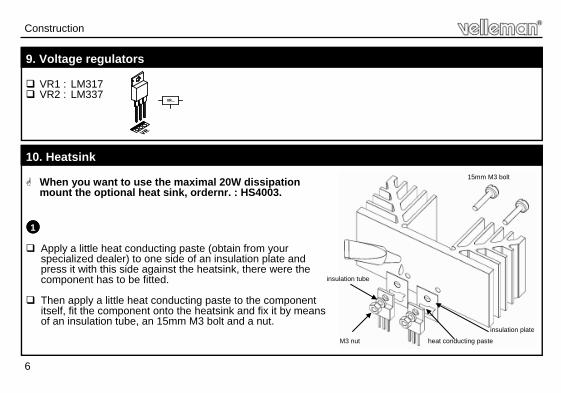
VR1 : LM317 VR2 : LM337
9. Voltage regulators
VR...
When you want to use the maximal 20W dissipation mount the optional heat sink, ordernr. : HS4003.
Apply a little heat conducting paste (obtain from your specialized dealer) to one side of an insulation plate and press it with this side against the heatsink, there were the component has to be fitted.
Then apply a little heat conducting paste to the component itself, fit the component onto the heatsink and fix it by means of an insulation tube, an 15mm M3 bolt and a nut.
10. Heatsink 15mm M3 bolt
insulation plate
M3 nut
insulation tube
1
heat conducting paste

7
Fit the components and heatsink onto the PCB and fix it by
means of two 5mm spacers and two screws.
Solder now the connections of the voltage regulators.
2
Heatsink construction
3
Screw
Spacer

8
Enclosure
When mounting the Kit into a enclosure, you have to drill two holes in the backside of the housing to pass the 15mm M3 bolts trough.
11. Using a metal enclosure as a heatsink
Heat conducting paste
15mm M3 bolt
Insulation plate
Insulation tube
M3 nut

9
12. Connection
enclosure
VA 0
Req. output voltage
Req. AC input voltage (transformer)
+/- 1,2 ... 5V 2 x 9VAC
+/- 5 ... 9V 2 x 12 - 15VAC
+/- 9 ... 12V 2 x 15VAC
+/- 12 ... 15V 2 x 18VAC
+/- 15 ... 18V 2 x 22VAC
Absolute max. AC input : 2 x 24VAC
0
VB

10
PCB
13. PCB layout

11
diagram
14. Diagram

5 4 1 0 3 2 9 3 2 7 1 3 2Modifications and typographical errors reserved © Velleman nv. H8042IP’1 - 2014 (rev.2)
VELLEMAN NV Legen Heirweg 33, B-9890 GAVERE
Belgium (Europe)