symantec cluster server 6.2installationguide-linux ·...
TRANSCRIPT
Symantec™ Cluster Server6.2 Installation Guide - Linux
January 2015

Symantec™ Cluster Server Installation GuideThe software described in this book is furnished under a license agreement and may be usedonly in accordance with the terms of the agreement.
Product version: 6.2
Document version: 6.2 Rev 2
Legal NoticeCopyright © 2015 Symantec Corporation. All rights reserved.
Symantec, the Symantec Logo, the Checkmark Logo, Veritas, Veritas Storage Foundation,CommandCentral, NetBackup, Enterprise Vault, and LiveUpdate are trademarks or registeredtrademarks of Symantec Corporation or its affiliates in the U.S. and other countries. Othernames may be trademarks of their respective owners.
The product described in this document is distributed under licenses restricting its use, copying,distribution, and decompilation/reverse engineering. No part of this document may bereproduced in any form by any means without prior written authorization of SymantecCorporation and its licensors, if any.
THE DOCUMENTATION IS PROVIDED "AS IS" AND ALL EXPRESS OR IMPLIEDCONDITIONS, REPRESENTATIONS AND WARRANTIES, INCLUDING ANY IMPLIEDWARRANTY OF MERCHANTABILITY, FITNESS FOR A PARTICULAR PURPOSE ORNON-INFRINGEMENT, ARE DISCLAIMED, EXCEPT TO THE EXTENT THAT SUCHDISCLAIMERS ARE HELD TO BE LEGALLY INVALID. SYMANTEC CORPORATION SHALLNOT BE LIABLE FOR INCIDENTAL OR CONSEQUENTIAL DAMAGES IN CONNECTIONWITH THE FURNISHING, PERFORMANCE, OR USE OF THIS DOCUMENTATION. THEINFORMATION CONTAINED IN THIS DOCUMENTATION IS SUBJECT TO CHANGEWITHOUT NOTICE.
The Licensed Software and Documentation are deemed to be commercial computer softwareas defined in FAR 12.212 and subject to restricted rights as defined in FAR Section 52.227-19"Commercial Computer Software - Restricted Rights" and DFARS 227.7202, "Rights inCommercial Computer Software or Commercial Computer Software Documentation", asapplicable, and any successor regulations, whether delivered by Symantec as on premisesor hosted services. Any use, modification, reproduction release, performance, display ordisclosure of the Licensed Software and Documentation by the U.S. Government shall besolely in accordance with the terms of this Agreement.

Symantec Corporation350 Ellis StreetMountain View, CA 94043
http://www.symantec.com
Technical SupportSymantec Technical Support maintains support centers globally. Technical Support’sprimary role is to respond to specific queries about product features and functionality.The Technical Support group also creates content for our online Knowledge Base.The Technical Support group works collaboratively with the other functional areaswithin Symantec to answer your questions in a timely fashion. For example, theTechnical Support group works with Product Engineering and Symantec SecurityResponse to provide alerting services and virus definition updates.
Symantec’s support offerings include the following:
■ A range of support options that give you the flexibility to select the right amountof service for any size organization
■ Telephone and/or Web-based support that provides rapid response andup-to-the-minute information
■ Upgrade assurance that delivers software upgrades
■ Global support purchased on a regional business hours or 24 hours a day, 7days a week basis
■ Premium service offerings that include Account Management Services
For information about Symantec’s support offerings, you can visit our website atthe following URL:
www.symantec.com/business/support/index.jsp
All support services will be delivered in accordance with your support agreementand the then-current enterprise technical support policy.
Contacting Technical SupportCustomers with a current support agreement may access Technical Supportinformation at the following URL:
www.symantec.com/business/support/contact_techsupp_static.jsp
Before contacting Technical Support, make sure you have satisfied the systemrequirements that are listed in your product documentation. Also, you should be atthe computer on which the problem occurred, in case it is necessary to replicatethe problem.
When you contact Technical Support, please have the following informationavailable:
■ Product release level
■ Hardware information
■ Available memory, disk space, and NIC information
■ Operating system
■ Version and patch level
■ Network topology
■ Router, gateway, and IP address information
■ Problem description:
■ Error messages and log files
■ Troubleshooting that was performed before contacting Symantec
■ Recent software configuration changes and network changes
Licensing and registrationIf your Symantec product requires registration or a license key, access our technicalsupport Web page at the following URL:
www.symantec.com/business/support/
Customer serviceCustomer service information is available at the following URL:
www.symantec.com/business/support/
Customer Service is available to assist with non-technical questions, such as thefollowing types of issues:
■ Questions regarding product licensing or serialization
■ Product registration updates, such as address or name changes
■ General product information (features, language availability, local dealers)
■ Latest information about product updates and upgrades
■ Information about upgrade assurance and support contracts
■ Information about the Symantec Buying Programs
■ Advice about Symantec's technical support options
■ Nontechnical presales questions
■ Issues that are related to CD-ROMs or manuals
DocumentationProduct guides are available on the media in PDF format. Make sure that you areusing the current version of the documentation. The document version appears on
page 2 of each guide. The latest product documentation is available on the Symantecwebsite.
https://sort.symantec.com/documents
Your feedback on product documentation is important to us. Send suggestions forimprovements and reports on errors or omissions. Include the title and documentversion (located on the second page), and chapter and section titles of the text onwhich you are reporting. Send feedback to:
For information regarding the latest HOWTO articles, documentation updates, orto ask a question regarding product documentation, visit the Storage and ClusteringDocumentation forum on Symantec Connect.
https://www-secure.symantec.com/connect/storage-management/forums/storage-and-clustering-documentation
Support agreement resourcesIf you want to contact Symantec regarding an existing support agreement, pleasecontact the support agreement administration team for your region as follows:
[email protected] and Japan
[email protected], Middle-East, and Africa
[email protected] America and Latin America
About Symantec ConnectSymantec Connect is the peer-to-peer technical community site for Symantec’senterprise customers. Participants can connect and share information with otherproduct users, including creating forum posts, articles, videos, downloads, blogsand suggesting ideas, as well as interact with Symantec product teams andTechnical Support. Content is rated by the community, and members receive rewardpoints for their contributions.
http://www.symantec.com/connect/storage-management
Technical Support ............................................................................................... 4
Section 1 Installation overview and planning .................. 22
Chapter 1 Introducing Symantec Cluster Server ............................. 23
About Symantec™ Cluster Server .................................................... 23About VCS basics ........................................................................ 23
About multiple nodes ............................................................... 24About shared storage .............................................................. 24About LLT and GAB ................................................................ 25About network channels for heartbeating ..................................... 25About preexisting network partitions ........................................... 26About VCS seeding ................................................................ 26
About VCS features ...................................................................... 27About VCS notifications ........................................................... 27About global clusters ............................................................... 27About I/O fencing ................................................................... 27
About VCS optional components .................................................... 29About Veritas Operations Manager ............................................. 29About Cluster Manager (Java Console) ....................................... 29About VCS Simulator .............................................................. 30
About Symantec Operations Readiness Tools .................................... 30About configuring VCS clusters for data integrity ................................. 32
About I/O fencing for VCS in virtual machines that do not supportSCSI-3 PR ...................................................................... 33
About I/O fencing components .................................................. 33About preferred fencing ........................................................... 35
Chapter 2 System requirements ......................................................... 37
Release notes ............................................................................. 37Important preinstallation information for VCS ...................................... 38Hardware requirements for VCS ...................................................... 38Disk space requirements ................................................................ 39Supported operating systems .......................................................... 39
Contents
Supported software for VCS ........................................................... 39I/O fencing requirements ................................................................ 40
Coordinator disk requirements for I/O fencing ............................... 40CP server requirements ........................................................... 41Non-SCSI-3 I/O fencing requirements ......................................... 44
Number of nodes supported ........................................................... 45Checking installed product versions and downloading maintenance
releases and patches .............................................................. 45Obtaining installer patches ............................................................. 46Disabling external network connection attempts .................................. 47
Chapter 3 Planning to install VCS ...................................................... 48
VCS installation methods ............................................................... 48About the script-based installer ................................................. 49About the VCS installation program ............................................ 51About the web-based installer ................................................... 53About response files ............................................................... 54
About installation and configuration methods ...................................... 55Typical VCS cluster setup models .................................................... 57
Typical configuration of two-node VCS cluster .............................. 58Typical configuration of VCS clusters in secure mode .................... 58Typical configuration of VOM-managed VCS clusters ..................... 59
Chapter 4 Licensing VCS ...................................................................... 61
About Symantec product licensing ................................................... 61Obtaining VCS license keys ............................................................ 62Installing Symantec product license keys ........................................... 63
Section 2 Preinstallation tasks .................................................. 65
Chapter 5 Preparing to install VCS ..................................................... 66
About preparing to install VCS ........................................................ 66Performing preinstallation tasks ....................................................... 66
Setting up the private network ................................................... 67Verifying network interfaces for persistent names .......................... 70About using ssh or rsh with the installer ...................................... 70Setting up shared storage ........................................................ 70Setting the PATH variable ........................................................ 74Setting the MANPATH variable .................................................. 74Setting the kernel.panic tunable ................................................. 74Setting the kernel.hung_task_panic tunable ................................. 75
8Contents
Optimizing LLT media speed settings on private NICs .................... 75Guidelines for setting the media speed of the LLT
interconnects ................................................................... 76VCS considerations for Blade server environments ....................... 76Mounting the product disc ........................................................ 76Performing automated preinstallation check ................................. 77Reformatting VCS configuration files on a stopped cluster .............. 78
Getting your VCS installation and configuration information ready .......... 79
Section 3 Installation using the script-basedinstaller ........................................................................ 86
Chapter 6 Installing VCS ....................................................................... 87
Installing VCS using the installer ...................................................... 87
Chapter 7 Preparing to configure VCS clusters for dataintegrity ........................................................................... 92
About planning to configure I/O fencing ............................................. 92Typical VCS cluster configuration with disk-based I/O
fencing ........................................................................... 96Typical VCS cluster configuration with server-based I/O
fencing ........................................................................... 97Recommended CP server configurations ..................................... 98
Setting up the CP server .............................................................. 101Planning your CP server setup ................................................ 101Installing the CP server using the installer .................................. 103Configuring the CP server cluster in secure mode ....................... 103Setting up shared storage for the CP server database .................. 104Configuring the CP server using the installer program .................. 105Configuring the CP server using the web-based installer ............... 117Configuring the CP server manually .......................................... 118Configuring CP server using response files ................................ 125Verifying the CP server configuration ........................................ 129
Chapter 8 Configuring VCS ................................................................. 131
Overview of tasks to configure VCS using the script-basedinstaller ............................................................................... 132
Starting the software configuration ................................................. 132Specifying systems for configuration ............................................... 133Configuring the cluster name ......................................................... 134
9Contents
Configuring private heartbeat links ................................................. 134Configuring the virtual IP of the cluster ............................................ 140Configuring Symantec Cluster Server in secure mode ........................ 142Setting up trust relationships for your VCS cluster ............................. 143Configuring a secure cluster node by node ...................................... 144
Configuring the first node ....................................................... 145Configuring the remaining nodes ............................................. 146Completing the secure cluster configuration ............................... 146
Adding VCS users ...................................................................... 149Configuring SMTP email notification ............................................... 150Configuring SNMP trap notification ................................................. 151Configuring global clusters ............................................................ 153Completing the VCS configuration .................................................. 154
Verifying the NIC configuration ................................................ 154Verifying and updating licenses on the system .................................. 155
Checking licensing information on the system ............................. 155Updating product licenses ...................................................... 156
Chapter 9 Configuring VCS clusters for data integrity ................. 158
Setting up disk-based I/O fencing using installvcs .............................. 158Initializing disks as VxVM disks ................................................ 158Configuring disk-based I/O fencing using installvcs ...................... 159Refreshing keys or registrations on the existing coordination points
for disk-based fencing using the installvcs ............................ 161Checking shared disks for I/O fencing ....................................... 163
Setting up server-based I/O fencing using installvcs ........................... 167Refreshing keys or registrations on the existing coordination points
for server-based fencing using the installvcs ......................... 175Setting the order of existing coordination points for server-based
fencing using the installvcs ............................................... 177Setting up non-SCSI-3 I/O fencing in virtual environments using
installvcs ............................................................................. 180Setting up majority-based I/O fencing using installvcs ......................... 182Enabling or disabling the preferred fencing policy .............................. 184
Section 4 Installation using the Web-basedinstaller ...................................................................... 187
Chapter 10 Installing VCS ..................................................................... 188
Before using the web-based installer .............................................. 188Starting the web-based installer ..................................................... 189
10Contents
Obtaining a security exception on Mozilla Firefox .............................. 189Performing a preinstallation check with the web-based installer ............ 190Installing VCS with the web-based installer ...................................... 190
Chapter 11 Configuring VCS ................................................................. 193
Configuring VCS using the web-based installer ................................. 193Configuring VCS for data integrity using the web-based installer ........... 199
Configuring disk-based fencing for data integrity using theweb-based installer ......................................................... 200
Configuring server-based fencing for data integrity using theweb-based installer ......................................................... 202
Configuring fencing in disabled mode using the web-basedinstaller ......................................................................... 204
Configuring fencing in majority mode using the web-basedinstaller ......................................................................... 205
Replacing, adding, or removing coordination points using theweb-based installer ......................................................... 206
Refreshing keys or registrations on the existing coordination pointsusing web-based installer ................................................. 208
Setting the order of existing coordination points using theweb-based installer ......................................................... 210
Section 5 Automated installation using responsefiles ............................................................................... 213
Chapter 12 Performing an automated VCS installation ................. 214
Installing VCS using response files ................................................. 214Response file variables to install VCS ............................................. 215Sample response file for installing VCS ........................................... 218
Chapter 13 Performing an automated VCS configuration ............. 220
Configuring VCS using response files ............................................. 220Response file variables to configure Symantec Cluster Server ............. 221Sample response file for configuring Symantec Cluster Server ............. 232
Chapter 14 Performing an automated I/O fencing configurationusing response files .................................................... 234
Configuring I/O fencing using response files ..................................... 234Response file variables to configure disk-based I/O fencing ................. 235
11Contents
Sample response file for configuring disk-based I/O fencing ................ 238Response file variables to configure server-based I/O fencing .............. 238Sample response file for configuring server-based I/O fencing ............. 240Response file variables to configure non-SCSI-3 I/O fencing ................ 241Sample response file for configuring non-SCSI-3 I/O fencing ............... 242Response file variables to configure majority-based I/O fencing ............ 243Sample response file for configuring majority-based I/O fencing ........... 243
Section 6 Manual installation ................................................... 245
Chapter 15 Performing preinstallation tasks ................................... 246
Requirements for installing VCS .................................................... 246
Chapter 16 Manually installing VCS ................................................... 247
About VCS manual installation ...................................................... 247Installing VCS software manually ................................................... 247
Viewing the list of VCS RPMs .................................................. 248Installing VCS RPMs for a manual installation ............................. 249Adding a license key for a manual installation ............................. 251Copying the installation guide to each node ............................... 253
Installing VCS using Kickstart ........................................................ 254Sample Kickstart configuration file .................................................. 256Installing Symantec Cluster Server using yum .................................. 258Installing VCS using the Red Hat Satellite server ............................... 263
Using Red Hat Satellite server to install VCS products .................. 264
Chapter 17 Manually configuring VCS ............................................... 266
About configuring VCS manually .................................................... 266Configuring LLT manually ............................................................. 267
Setting up /etc/llthosts for a manual installation ........................... 267Setting up /etc/llttab for a manual installation .............................. 268About LLT directives in /etc/llttab file ......................................... 268Additional considerations for LLT for a manual installation ............. 270
Configuring GAB manually ............................................................ 270Configuring VCS manually ............................................................ 270
Configuring the cluster UUID when creating a clustermanually ....................................................................... 272
Configuring VCS in single node mode ............................................. 272Disabling LLT, GAB, and I/O fencing on a single node
cluster .......................................................................... 272Enabling LLT, GAB, and I/O fencing .......................................... 274
12Contents
Starting LLT, GAB, and VCS after manual configuration ...................... 274About configuring cluster using VCS Cluster Configuration wizard ........ 276Before configuring a VCS cluster using the VCS Cluster Configuration
wizard ................................................................................ 277Launching the VCS Cluster Configuration wizard ............................... 278Configuring a cluster by using the VCS cluster configuration
wizard ................................................................................ 279Adding a system to a VCS cluster .................................................. 283Modifying the VCS configuration .................................................... 285
Configuring the ClusterService group ........................................ 285
Chapter 18 Manually configuring the clusters for dataintegrity ......................................................................... 286
Setting up disk-based I/O fencing manually ...................................... 286Identifying disks to use as coordinator disks ............................... 287Setting up coordinator disk groups ........................................... 287Creating I/O fencing configuration files ...................................... 288Modifying VCS configuration to use I/O fencing ........................... 289Verifying I/O fencing configuration ............................................ 291
Setting up server-based I/O fencing manually ................................... 291Preparing the CP servers manually for use by the VCS
cluster .......................................................................... 292Generating the client key and certificates manually on the client
nodes .......................................................................... 295Configuring server-based fencing on the VCS cluster
manually ....................................................................... 297Configuring CoordPoint agent to monitor coordination points ......... 304Verifying server-based I/O fencing configuration .......................... 305
Setting up non-SCSI-3 fencing in virtual environments manually ........... 306Sample /etc/vxfenmode file for non-SCSI-3 fencing ...................... 308
Setting up majority-based I/O fencing manually ................................ 312Creating I/O fencing configuration files ...................................... 312Modifying VCS configuration to use I/O fencing ........................... 312Verifying I/O fencing configuration ............................................ 314Sample /etc/vxfenmode file for majority-based fencing .................. 315
13Contents
Section 7 Managing your Symantecdeployments ........................................................... 316
Chapter 19 Performing centralized installations using theDeployment Server ...................................................... 317
About the Deployment Server ........................................................ 318Deployment Server overview ......................................................... 319Installing the Deployment Server .................................................... 320Setting up a Deployment Server .................................................... 321Setting deployment preferences ..................................................... 324Specifying a non-default repository location ...................................... 326Downloading the most recent release information .............................. 326Loading release information and patches on to your Deployment
Server ................................................................................ 327Viewing or downloading available release images ............................. 328Viewing or removing repository images stored in your repository .......... 333Deploying Symantec product updates to your environment .................. 335Finding out which releases you have installed, and which upgrades or
updates you may need .......................................................... 336Defining Install Bundles ................................................................ 338Creating Install Templates ............................................................ 343Deploying Symantec releases ....................................................... 345Connecting the Deployment Server to SORT using a proxy
server ................................................................................. 348
Section 8 Upgrading VCS ............................................................ 349
Chapter 20 Planning to upgrade VCS ................................................. 350
About upgrading to VCS 6.2 .......................................................... 350Supported upgrade paths for VCS 6.2 ............................................. 351Upgrading VCS in secure enterprise environments ............................ 355Considerations for upgrading secure VCS 5.x clusters to VCS
6.2 ..................................................................................... 356Considerations for upgrading VCS to 6.2 on systems configured with
an Oracle resource ............................................................... 357Considerations for upgrading secure VCS clusters to VCS 6.2 ............. 357Considerations for upgrading secure CP servers ............................... 358Considerations for upgrading secure CP clients ................................ 358Setting up trust relationship between CP server and CP clients
manually ............................................................................. 358
14Contents
Using Install Bundles to simultaneously install or upgrade full releases(base, maintenance, rolling patch), and individual patches ............ 359
Chapter 21 Performing a typical VCS upgrade using theinstaller .......................................................................... 362
Before upgrading VCS using the script-based or web-basedinstaller ............................................................................... 362
Upgrading VCS using the script-based installer ................................. 362Upgrading VCS using the web-based installer .................................. 364
Chapter 22 Performing an online upgrade ........................................ 367
Limitations of online upgrade ......................................................... 367Upgrading VCS online using the script-based installer ........................ 368Upgrading VCS online using the web-based installer .......................... 369
Chapter 23 Performing a phased upgrade of VCS ........................... 372
About phased upgrade ................................................................ 372Prerequisites for a phased upgrade .......................................... 372Planning for a phased upgrade ................................................ 373Phased upgrade limitations ..................................................... 373Phased upgrade example ....................................................... 373Phased upgrade example overview .......................................... 374
Performing a phased upgrade using the script-based installer .............. 375Moving the service groups to the second subcluster ..................... 375Upgrading the operating system on the first subcluster ................. 378Upgrading the first subcluster .................................................. 379Preparing the second subcluster .............................................. 381Activating the first subcluster ................................................... 384Upgrading the operating system on the second subcluster ............ 385Upgrading the second subcluster ............................................. 386Finishing the phased upgrade ................................................. 387
Chapter 24 Performing an automated VCS upgrade usingresponse files ............................................................... 390
Upgrading VCS using response files ............................................... 390Response file variables to upgrade VCS .......................................... 391Sample response file for upgrading VCS ......................................... 393Performing rolling upgrade of VCS using response files ...................... 393Response file variables to upgrade VCS using rolling upgrade ............. 394Sample response file for VCS using rolling upgrade ........................... 396
15Contents
Chapter 25 Performing a rolling upgrade .......................................... 398
About rolling upgrades ................................................................. 398Supported rolling upgrade paths .................................................... 401Performing a rolling upgrade using the installer ................................. 401
Performing a rolling upgrade using the script-based installer .......... 401Performing a rolling upgrade of VCS using the web-based
installer ............................................................................... 404
Section 9 Post-installation tasks ............................................ 408
Chapter 26 Performing post-installation tasks ................................ 409
About enabling LDAP authentication for clusters that run in securemode ................................................................................. 409Enabling LDAP authentication for clusters that run in secure
mode ........................................................................... 411Accessing the VCS documentation ................................................. 415Removing permissions for communication ....................................... 416
Chapter 27 Installing or upgrading VCS components ..................... 417
Installing the Java Console ........................................................... 417Software requirements for the Java Console .............................. 417Hardware requirements for the Java Console ............................. 418Installing the Java Console on Linux ......................................... 418Installing the Java Console on a Windows system ....................... 419
Upgrading the Java Console ......................................................... 419Installing VCS Simulator ............................................................... 420
Software requirements for VCS Simulator .................................. 420Installing VCS Simulator on Windows systems ............................ 420Reviewing the installation ....................................................... 420
Upgrading VCS Simulator ............................................................. 421Upgrading the VCS agents ........................................................... 422
Chapter 28 Verifying the VCS installation ......................................... 423
About verifying the VCS installation ................................................ 423About the cluster UUID ................................................................ 423Verifying the LLT, GAB, and VCS configuration files ........................... 424Verifying LLT, GAB, and cluster operation ........................................ 424
Verifying LLT ........................................................................ 425Verifying GAB ...................................................................... 427Verifying the cluster ............................................................... 428
16Contents
Verifying the cluster nodes ...................................................... 429Upgrading the disk group version ................................................... 432Performing a postcheck on a node ................................................. 433
About using the postcheck option ............................................. 433
Section 10 Adding and removing cluster nodes ............... 436
Chapter 29 Adding a node to a single-node cluster ........................ 437
Adding a node to a single-node cluster ............................................ 437Setting up a node to join the single-node cluster .......................... 438Installing and configuring Ethernet cards for private network .......... 439Configuring the shared storage ................................................ 440Bringing up the existing node .................................................. 440Installing the VCS software manually when adding a node to a
single node cluster .......................................................... 441Creating configuration files ..................................................... 441Starting LLT and GAB ............................................................ 441Reconfiguring VCS on the existing node .................................... 442Verifying configuration on both nodes ....................................... 443
Chapter 30 Adding a node to a multi-node VCS cluster ................. 444
Adding nodes using the VCS installer ............................................. 444Adding a node using the web-based installer .................................... 447Manually adding a node to a cluster ................................................ 448
Setting up the hardware ......................................................... 449Installing the VCS software manually when adding a node ............ 450Setting up the node to run in secure mode ................................. 450Configuring LLT and GAB when adding a node to the cluster ......... 453Configuring I/O fencing on the new node ................................... 456Adding the node to the existing cluster ...................................... 459Starting VCS and verifying the cluster ....................................... 460Adding a node using response files .......................................... 460
Chapter 31 Removing a node from a VCS cluster ............................ 463
Removing a node from a VCS cluster ............................................. 463Verifying the status of nodes and service groups ......................... 464Deleting the departing node from VCS configuration .................... 465Modifying configuration files on each remaining node ................... 468Removing the node configuration from the CP server ................... 468Removing security credentials from the leaving node .................. 469
17Contents
Unloading LLT and GAB and removing VCS on the departingnode ............................................................................ 470
Section 11 Uninstallation of VCS .............................................. 472
Chapter 32 Uninstalling VCS using the installer .............................. 473
Preparing to uninstall VCS ............................................................ 473Uninstalling VCS using the script-based installer ............................... 474
Removing VCS 6.2 RPMs ...................................................... 474Running uninstallvcs from the VCS 6.2 disc ............................... 475
Uninstalling VCS with the web-based installer ................................... 475Removing the CP server configuration using the installer
program .............................................................................. 476
Chapter 33 Uninstalling VCS using response files .......................... 479
Uninstalling VCS using response files ............................................. 479Response file variables to uninstall VCS .......................................... 480Sample response file for uninstalling VCS ........................................ 481
Chapter 34 Manually uninstalling VCS .............................................. 482
Removing VCS RPMs manually ..................................................... 482Manually remove the CP server fencing configuration ........................ 483Manually deleting cluster details from a CP server ............................. 484
Section 12 Installation reference .............................................. 487
Appendix A Services and ports ............................................................. 488
About SFHA services and ports ..................................................... 488
Appendix B VCS installation RPMs ...................................................... 490
Symantec Cluster Server installation RPMs ...................................... 490
Appendix C Installation command options ........................................ 493
Command options for installvcs ..................................................... 493Installation script options .............................................................. 494Command options for uninstallvcs .................................................. 500
18Contents
Appendix D Configuration files ............................................................. 501
About the LLT and GAB configuration files ....................................... 501About the AMF configuration files ................................................... 504About the VCS configuration files ................................................... 505
Sample main.cf file for VCS clusters ......................................... 506Sample main.cf file for global clusters ....................................... 508
About I/O fencing configuration files ................................................ 510Sample configuration files for CP server .......................................... 512
Sample main.cf file for CP server hosted on a single node thatruns VCS ...................................................................... 513
Sample main.cf file for CP server hosted on a two-node SFHAcluster .......................................................................... 515
Sample CP server configuration (/etc/vxcps.conf) file output .......... 518
Appendix E Installing VCS on a single node ...................................... 519
About installing VCS on a single node ............................................. 519Creating a single-node cluster using the installer program ................... 520
Preparing for a single node installation ...................................... 520Starting the installer for the single node cluster ........................... 520
Creating a single-node cluster manually .......................................... 521Setting the path variable for a manual single node installation .............. 521Installing VCS software manually on a single node ............................ 522Modifying the startup files ............................................................. 522Configuring VCS ......................................................................... 522Verifying single-node operation ...................................................... 522
Appendix F Configuring LLT over UDP ............................................... 523
Using the UDP layer for LLT .......................................................... 523When to use LLT over UDP .................................................... 523
Manually configuring LLT over UDP using IPv4 ................................. 523Broadcast address in the /etc/llttab file ...................................... 524The link command in the /etc/llttab file ....................................... 525The set-addr command in the /etc/llttab file ................................ 525Selecting UDP ports .............................................................. 526Configuring the netmask for LLT .............................................. 526Configuring the broadcast address for LLT ................................. 527Sample configuration: direct-attached links ................................ 527Sample configuration: links crossing IP routers ........................... 529
Manually configuring LLT over UDP using IPv6 ................................. 530The link command in the /etc/llttab file ....................................... 531The set-addr command in the /etc/llttab file ................................ 531
19Contents
Selecting UDP ports .............................................................. 532Sample configuration: direct-attached links ................................ 532Sample configuration: links crossing IP routers ........................... 534
LLT over UDP sample /etc/llttab ..................................................... 535
Appendix G Using LLT over RDMA ....................................................... 536
Using LLT over RDMA ................................................................. 536About RDMA over RoCE or InfiniBand networks in a clustering
environment ........................................................................ 536How LLT supports RDMA capability for faster interconnects between
applications ......................................................................... 537Using LLT over RDMA: supported use cases ................................... 538Configuring LLT over RDMA ......................................................... 538
Choosing supported hardware for LLT over RDMA ...................... 539Installing RDMA, InfiniBand or Ethernet drivers and utilities ........... 540Configuring RDMA over an Ethernet network .............................. 541Configuring RDMA over an InfiniBand network ............................ 543Tuning system performance .................................................... 547Manually configuring LLT over RDMA ....................................... 549LLT over RDMA sample /etc/llttab ............................................ 553Verifying LLT configuration ...................................................... 553
Troubleshooting LLT over RDMA ................................................... 554IP addresses associated to the RDMA NICs do not automatically
plumb on node restart ...................................................... 554Ping test fails for the IP addresses configured over InfiniBand
interfaces. .................................................................... 555After a node restart, by default the Mellanox card with Virtual
Protocol Interconnect (VPI) gets configured in InfiniBandmode ........................................................................... 555
The LLT module fails to start ................................................... 555
Appendix H Configuring the secure shell or the remote shell forcommunications .......................................................... 557
About configuring secure shell or remote shell communication modesbefore installing products ........................................................ 557
Manually configuring passwordless ssh ........................................... 558Setting up ssh and rsh connection using the installer -comsetup
command ............................................................................ 561Setting up ssh and rsh connection using the pwdutil.pl utility ................ 562Restarting the ssh session ............................................................ 565Enabling rsh for Linux .................................................................. 565
20Contents
Appendix I Troubleshooting VCS installation .................................. 568
What to do if you see a licensing reminder ....................................... 568Restarting the installer after a failed connection ................................ 569Starting and stopping processes for the Symantec products ............... 569Installer cannot create UUID for the cluster ...................................... 570LLT startup script displays errors .................................................... 571The vxfentsthdw utility fails when SCSI TEST UNIT READY command
fails .................................................................................... 571Issues during fencing startup on VCS cluster nodes set up for
server-based fencing ............................................................. 572
Appendix J Sample VCS cluster setup diagrams for CPserver-based I/O fencing ............................................ 573
Configuration diagrams for setting up server-based I/O fencing ............ 573Two unique client clusters served by 3 CP servers ....................... 573Client cluster served by highly available CPS and 2 SCSI-3
disks ............................................................................ 574Two node campus cluster served by remote CP server and 2
SCSI-3 disks .................................................................. 576Multiple client clusters served by highly available CP server and
2 SCSI-3 disks ............................................................... 578
Appendix K Compatibility issues when installing SymantecCluster Server with other products ......................... 580
Installing, uninstalling, or upgrading Storage Foundation products whenother Symantec products are present ........................................ 580
Installing, uninstalling, or upgrading Storage Foundation products whenVOM is already present .......................................................... 581
Installing, uninstalling, or upgrading Storage Foundation products whenApplicationHA is already present .............................................. 581
Installing, uninstalling, or upgrading Storage Foundation products whenNetBackup is already present .................................................. 582
Appendix L Upgrading the Steward process ..................................... 583
Upgrading the Steward process ..................................................... 583
Index ................................................................................................................... 585
21Contents
Installation overview andplanning
■ Chapter 1. Introducing Symantec Cluster Server
■ Chapter 2. System requirements
■ Chapter 3. Planning to install VCS
■ Chapter 4. Licensing VCS
1Section
Introducing SymantecCluster Server
This chapter includes the following topics:
■ About Symantec™ Cluster Server
■ About VCS basics
■ About VCS features
■ About VCS optional components
■ About Symantec Operations Readiness Tools
■ About configuring VCS clusters for data integrity
About Symantec™ Cluster ServerSymantec™ Cluster Server by Symantec is a high-availability solution forapplications and services configured in a cluster. Symantec Cluster Server (VCS)monitors systems and application services, and restarts services when hardwareor software fails.
About VCS basicsA single VCS cluster consists of multiple systems that are connected in variouscombinations to storage devices. When a system is part of a VCS cluster, it is calleda node. VCS monitors and controls applications running in the cluster on nodes,and restarts applications in response to a variety of hardware or software faults.
Applications can continue to operate with little or no downtime. In some cases, suchas NFS, this continuation is transparent to high-level applications and users. In
1Chapter
other cases, a user might have to retry an operation, such as a Web server reloadinga page.
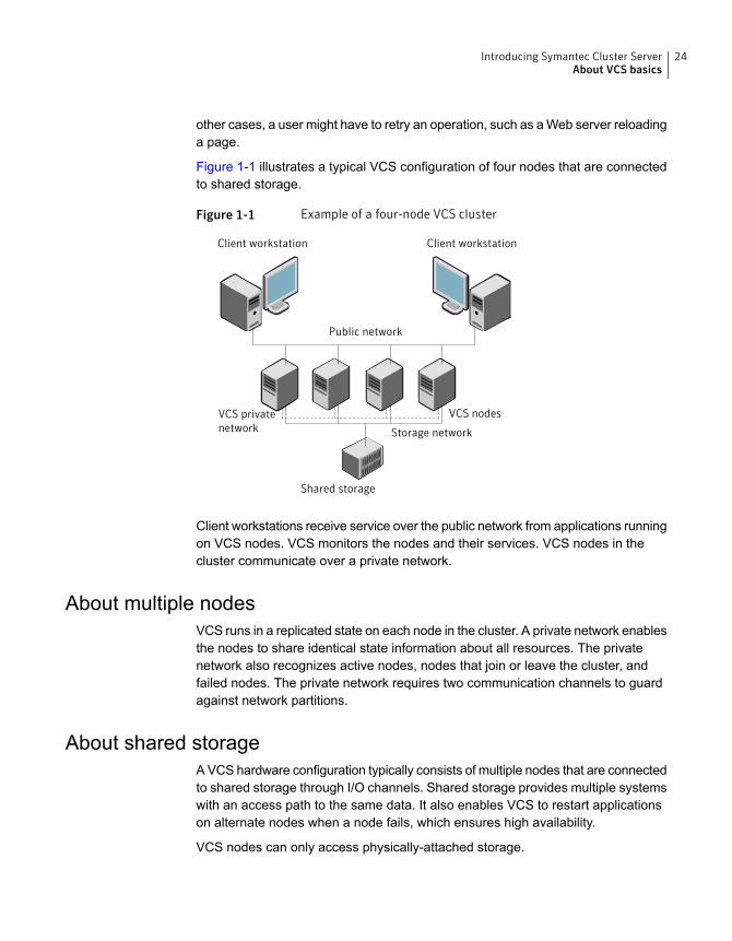
Figure 1-1 illustrates a typical VCS configuration of four nodes that are connectedto shared storage.
Figure 1-1 Example of a four-node VCS cluster
Client workstation Client workstation
Public network
Shared storage
VCS privatenetwork
VCS nodes
Storage network
Client workstations receive service over the public network from applications runningon VCS nodes. VCS monitors the nodes and their services. VCS nodes in thecluster communicate over a private network.
About multiple nodesVCS runs in a replicated state on each node in the cluster. A private network enablesthe nodes to share identical state information about all resources. The privatenetwork also recognizes active nodes, nodes that join or leave the cluster, andfailed nodes. The private network requires two communication channels to guardagainst network partitions.
About shared storageA VCS hardware configuration typically consists of multiple nodes that are connectedto shared storage through I/O channels. Shared storage provides multiple systemswith an access path to the same data. It also enables VCS to restart applicationson alternate nodes when a node fails, which ensures high availability.
VCS nodes can only access physically-attached storage.
24Introducing Symantec Cluster ServerAbout VCS basics

Figure 1-2 illustrates the flexibility of VCS shared storage configurations.
Figure 1-2 Two examples of shared storage configurations
Fully shared storage Distributed shared storage
About LLT and GABVCS uses two components, LLT and GAB, to share data over private networksamong systems. These components provide the performance and reliability thatVCS requires.
LLT (Low Latency Transport) provides fast kernel-to-kernel communications, andmonitors network connections.
GAB (Group Membership and Atomic Broadcast) provides globally ordered messagethat is required to maintain a synchronized state among the nodes.
About network channels for heartbeatingFor the VCS private network, two network channels must be available to carryheartbeat information. These network connections also transmit other VCS-relatedinformation.
Each cluster configuration requires at least two network channels between thesystems. The requirement for two channels protects your cluster against networkpartitioning. For more information on network partitioning, refer to the SymantecCluster Server Administrator's Guide.
Figure 1-3 illustrates a two-node VCS cluster where the nodes sys1 and sys2 havetwo private network connections.
25Introducing Symantec Cluster ServerAbout VCS basics
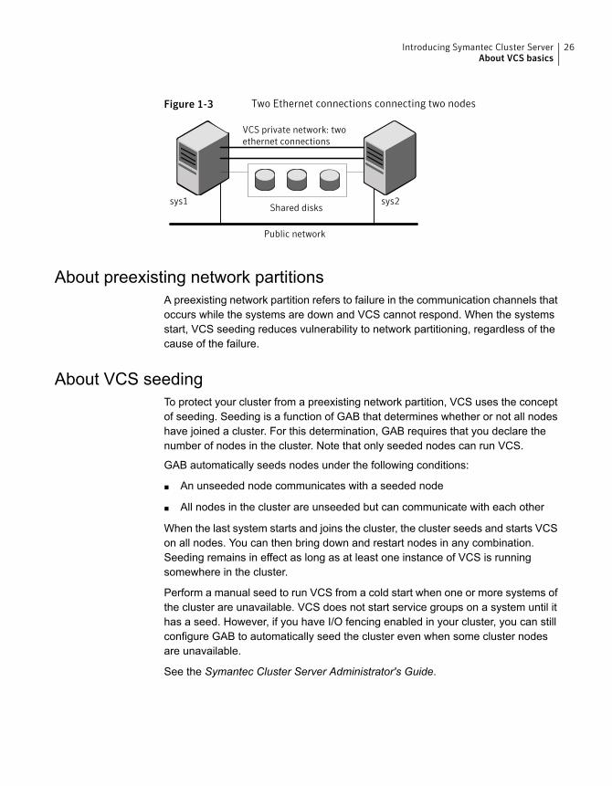
Figure 1-3 Two Ethernet connections connecting two nodes
VCS private network: twoethernet connections
Shared disks
Public network
sys1 sys2
About preexisting network partitionsA preexisting network partition refers to failure in the communication channels thatoccurs while the systems are down and VCS cannot respond. When the systemsstart, VCS seeding reduces vulnerability to network partitioning, regardless of thecause of the failure.
About VCS seedingTo protect your cluster from a preexisting network partition, VCS uses the conceptof seeding. Seeding is a function of GAB that determines whether or not all nodeshave joined a cluster. For this determination, GAB requires that you declare thenumber of nodes in the cluster. Note that only seeded nodes can run VCS.
GAB automatically seeds nodes under the following conditions:
■ An unseeded node communicates with a seeded node
■ All nodes in the cluster are unseeded but can communicate with each other
When the last system starts and joins the cluster, the cluster seeds and starts VCSon all nodes. You can then bring down and restart nodes in any combination.Seeding remains in effect as long as at least one instance of VCS is runningsomewhere in the cluster.
Perform a manual seed to run VCS from a cold start when one or more systems ofthe cluster are unavailable. VCS does not start service groups on a system until ithas a seed. However, if you have I/O fencing enabled in your cluster, you can stillconfigure GAB to automatically seed the cluster even when some cluster nodesare unavailable.
See the Symantec Cluster Server Administrator's Guide.
26Introducing Symantec Cluster ServerAbout VCS basics
About VCS featuresVCS offers the following features that you can configure during VCS configuration:
See “About VCS notifications” on page 27.VCS notifications
See “About global clusters” on page 27.VCS global clusters
See “About I/O fencing” on page 27.I/O fencing
About VCS notificationsYou can configure both Simple Network Management Protocol (SNMP) and SimpleMail Transfer Protocol (SMTP) notifications for VCS. Symantec recommends youto configure at least one of these notifications. You have the following options:
■ Configure SNMP trap notification of VCS events using the VCS Notifiercomponent.
■ Configure SMTP email notification of VCS events using the VCS Notifiercomponent.
See the Symantec Cluster Server Administrator's Guide for details on configuringthese notifications.
About global clustersGlobal clusters provide the ability to fail over applications between geographicallydistributed clusters when disaster occurs. You require a separate license to configureglobal clusters. You must add this license during the installation. The installer onlyasks about configuring global clusters if you have used the global cluster license.
See the Symantec Cluster Server Administrator's Guide.
About I/O fencingI/O fencing protects the data on shared disks when nodes in a cluster detect achange in the cluster membership that indicates a split-brain condition.
The fencing operation determines the following:
■ The nodes that must retain access to the shared storage
■ The nodes that must be ejected from the cluster
This decision prevents possible data corruption. The installer installs the I/O fencingdriver, part of VRTSvxfen RPM, when you install VCS. To protect data on shareddisks, you must configure I/O fencing after you install and configure VCS.
27Introducing Symantec Cluster ServerAbout VCS features
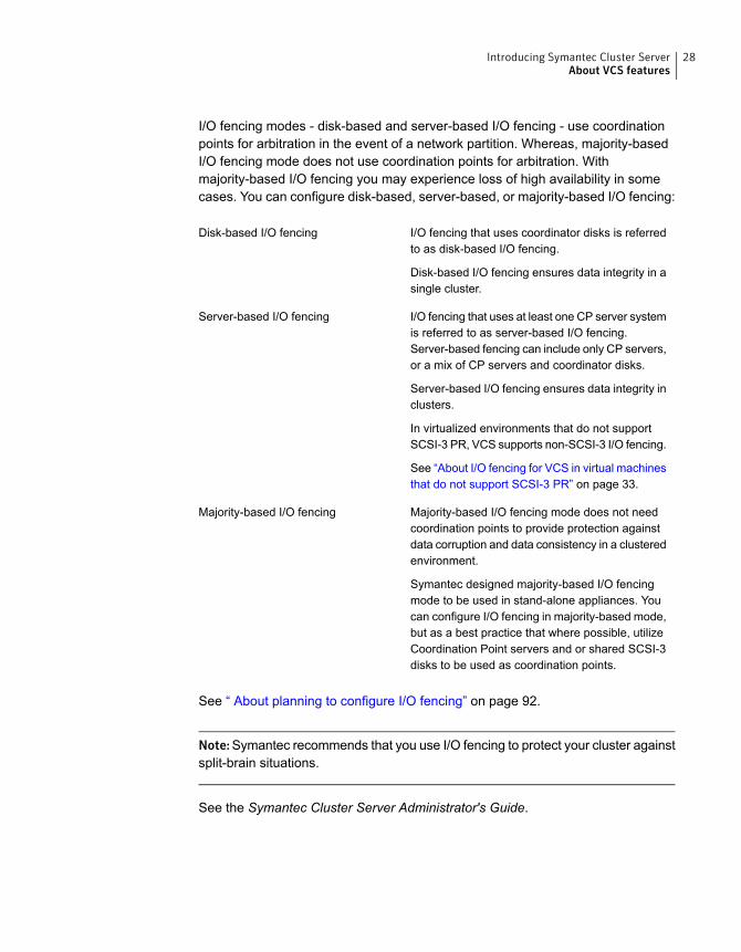
I/O fencing modes - disk-based and server-based I/O fencing - use coordinationpoints for arbitration in the event of a network partition. Whereas, majority-basedI/O fencing mode does not use coordination points for arbitration. Withmajority-based I/O fencing you may experience loss of high availability in somecases. You can configure disk-based, server-based, or majority-based I/O fencing:
I/O fencing that uses coordinator disks is referredto as disk-based I/O fencing.
Disk-based I/O fencing ensures data integrity in asingle cluster.
Disk-based I/O fencing
I/O fencing that uses at least one CP server systemis referred to as server-based I/O fencing.Server-based fencing can include only CP servers,or a mix of CP servers and coordinator disks.
Server-based I/O fencing ensures data integrity inclusters.
In virtualized environments that do not supportSCSI-3 PR, VCS supports non-SCSI-3 I/O fencing.
See “About I/O fencing for VCS in virtual machinesthat do not support SCSI-3 PR” on page 33.
Server-based I/O fencing
Majority-based I/O fencing mode does not needcoordination points to provide protection againstdata corruption and data consistency in a clusteredenvironment.
Symantec designed majority-based I/O fencingmode to be used in stand-alone appliances. Youcan configure I/O fencing in majority-based mode,but as a best practice that where possible, utilizeCoordination Point servers and or shared SCSI-3disks to be used as coordination points.
Majority-based I/O fencing
See “ About planning to configure I/O fencing” on page 92.
Note:Symantec recommends that you use I/O fencing to protect your cluster againstsplit-brain situations.
See the Symantec Cluster Server Administrator's Guide.
28Introducing Symantec Cluster ServerAbout VCS features
About VCS optional componentsYou can add the following optional components to VCS:
See “About Veritas Operations Manager” on page 29.Veritas Operations Manager
See “About Cluster Manager (Java Console)” on page 29.Cluster Manager (Java console)
See “About VCS Simulator” on page 30.VCS Simulator
About Veritas Operations ManagerVeritas Operations Manager provides a centralized management console forSymantec Storage Foundation and High Availability products. You can use VeritasOperations Manager to monitor, visualize, and manage storage resources andgenerate reports.
Symantec recommends using Veritas Operations Manager (VOM) to manageStorage Foundation and Cluster Server environments.
You can download Veritas Operations Manager from http://go.symantec.com/vom.
Refer to the Veritas Operations Manager documentation for installation, upgrade,and configuration instructions.
If you want to manage a single cluster using Cluster Manager (Java Console), aversion is available for download fromhttp://www.symantec.com/operations-manager/support. You cannot manage thenew features of this release using the Java Console. Symantec Cluster ServerManagement Console is deprecated.
About Cluster Manager (Java Console)Cluster Manager (Java Console) offers administration capabilities for your cluster.Use the different views in the Java Console to monitor and manage clusters andSymantec Cluster Server (VCS) objects, including service groups, systems,resources, and resource types. You cannot manage the new features of releases6.0 and later using the Java Console.
See Symantec Cluster Server Administrator's Guide.
You can download the console fromhttp://www.symantec.com/operations-manager/support.
29Introducing Symantec Cluster ServerAbout VCS optional components

About VCS SimulatorVCS Simulator enables you to simulate and test cluster configurations. Use VCSSimulator to view and modify service group and resource configurations and testfailover behavior. VCS Simulator can be run on a stand-alone system and does notrequire any additional hardware. You can install VCS Simulator only on a Windowsoperating system.
VCS Simulator runs an identical version of the VCS High Availability Daemon (HAD)as in a cluster, ensuring that failover decisions are identical to those in an actualcluster.
You can test configurations from different operating systems using VCS Simulator.For example, you can run VCS Simulator to test configurations for VCS clusters onWindows, AIX, HP-UX, Linux, and Solaris operating systems. VCS Simulator alsoenables creating and testing global clusters.
You can administer VCS Simulator from the Java Console or from the commandline.
To download VCS Simulator, go tohttp://www.symantec.com/operations-manager/support.
About Symantec Operations Readiness ToolsSymantec Operations Readiness Tools (SORT) is a website that automates andsimplifies some of the most time-consuming administrative tasks. It helps you identifyrisks in your datacenters and improve operational efficiency, enabling you to managethe complexity that is associated with datacenter architectures and scale.
Table 1-1 lists three major datacenter tasks and the SORT tools that can help youaccomplish them.
30Introducing Symantec Cluster ServerAbout Symantec Operations Readiness Tools
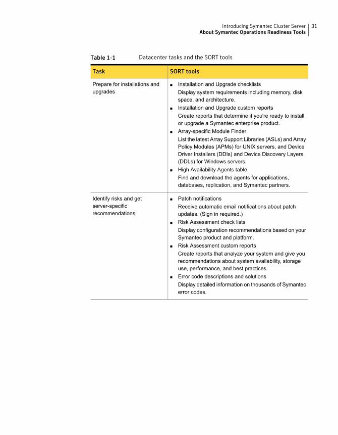
Table 1-1 Datacenter tasks and the SORT tools
SORT toolsTask
■ Installation and Upgrade checklistsDisplay system requirements including memory, diskspace, and architecture.
■ Installation and Upgrade custom reportsCreate reports that determine if you're ready to installor upgrade a Symantec enterprise product.
■ Array-specific Module FinderList the latest Array Support Libraries (ASLs) and ArrayPolicy Modules (APMs) for UNIX servers, and DeviceDriver Installers (DDIs) and Device Discovery Layers(DDLs) for Windows servers.
■ High Availability Agents tableFind and download the agents for applications,databases, replication, and Symantec partners.
Prepare for installations andupgrades
■ Patch notificationsReceive automatic email notifications about patchupdates. (Sign in required.)
■ Risk Assessment check listsDisplay configuration recommendations based on yourSymantec product and platform.
■ Risk Assessment custom reportsCreate reports that analyze your system and give yourecommendations about system availability, storageuse, performance, and best practices.
■ Error code descriptions and solutionsDisplay detailed information on thousands of Symantecerror codes.
Identify risks and getserver-specificrecommendations
31Introducing Symantec Cluster ServerAbout Symantec Operations Readiness Tools
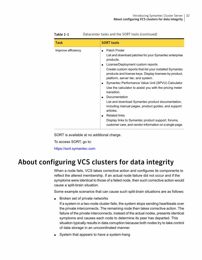
Table 1-1 Datacenter tasks and the SORT tools (continued)
SORT toolsTask
■ Patch FinderList and download patches for your Symantec enterpriseproducts.
■ License/Deployment custom reportsCreate custom reports that list your installed Symantecproducts and license keys. Display licenses by product,platform, server tier, and system.
■ Symantec Performance Value Unit (SPVU) CalculatorUse the calculator to assist you with the pricing metertransition.
■ DocumentationList and download Symantec product documentation,including manual pages, product guides, and supportarticles.
■ Related linksDisplay links to Symantec product support, forums,customer care, and vendor information on a single page.
Improve efficiency
SORT is available at no additional charge.
To access SORT, go to:
https://sort.symantec.com
About configuring VCS clusters for data integrityWhen a node fails, VCS takes corrective action and configures its components toreflect the altered membership. If an actual node failure did not occur and if thesymptoms were identical to those of a failed node, then such corrective action wouldcause a split-brain situation.
Some example scenarios that can cause such split-brain situations are as follows:
■ Broken set of private networksIf a system in a two-node cluster fails, the system stops sending heartbeats overthe private interconnects. The remaining node then takes corrective action. Thefailure of the private interconnects, instead of the actual nodes, presents identicalsymptoms and causes each node to determine its peer has departed. Thissituation typically results in data corruption because both nodes try to take controlof data storage in an uncoordinated manner.
■ System that appears to have a system-hang
32Introducing Symantec Cluster ServerAbout configuring VCS clusters for data integrity
If a system is so busy that it appears to stop responding, the other nodes coulddeclare it as dead. This declaration may also occur for the nodes that use thehardware that supports a "break" and "resume" function. When a node dropsto PROM level with a break and subsequently resumes operations, the othernodes may declare the system dead. They can declare it dead even if the systemlater returns and begins write operations.
I/O fencing is a feature that prevents data corruption in the event of a communicationbreakdown in a cluster. VCS uses I/O fencing to remove the risk that is associatedwith split-brain. I/O fencing allows write access for members of the active cluster.It blocks access to storage from non-members so that even a node that is alive isunable to cause damage.
After you install and configure VCS, you must configure I/O fencing in VCS to ensuredata integrity.
See “ About planning to configure I/O fencing” on page 92.
About I/O fencing for VCS in virtual machines that do not supportSCSI-3 PR
In a traditional I/O fencing implementation, where the coordination points arecoordination point servers (CP servers) or coordinator disks, Clustered VolumeManager (CVM) and Veritas I/O fencing modules provide SCSI-3 persistentreservation (SCSI-3 PR) based protection on the data disks. This SCSI-3 PRprotection ensures that the I/O operations from the losing node cannot reach a diskthat the surviving sub-cluster has already taken over.
See the Symantec Cluster Server Administrator's Guide for more information onhow I/O fencing works.
In virtualized environments that do not support SCSI-3 PR, VCS attempts to providereasonable safety for the data disks. VCS requires you to configure non-SCSI-3I/O fencing in such environments. Non-SCSI-3 fencing either uses majority-basedI/O fencing with only CP servers as coordination points or majority-based I/O fencing,which does not use coordination points, along with some additional configurationchanges to support such environments.
See “Setting up non-SCSI-3 I/O fencing in virtual environments using installvcs”on page 180.
See “Setting up non-SCSI-3 fencing in virtual environments manually” on page 306.
About I/O fencing componentsThe shared storage for VCS must support SCSI-3 persistent reservations to enableI/O fencing. VCS involves two types of shared storage:
33Introducing Symantec Cluster ServerAbout configuring VCS clusters for data integrity
■ Data disks—Store shared dataSee “About data disks” on page 34.
■ Coordination points—Act as a global lock during membership changesSee “About coordination points” on page 34.
About data disksData disks are standard disk devices for data storage and are either physical disksor RAID Logical Units (LUNs).
These disks must support SCSI-3 PR and must be part of standard VxVM diskgroups. VxVM is responsible for fencing data disks on a disk group basis. Disksthat are added to a disk group and new paths that are discovered for a device areautomatically fenced.
Note: Disk based fencing is possible only if VxVM is also present long with VCS.
About coordination pointsCoordination points provide a lock mechanism to determine which nodes get tofence off data drives from other nodes. A node must eject a peer from thecoordination points before it can fence the peer from the data drives. VCS preventssplit-brain when vxfen races for control of the coordination points and the winnerpartition fences the ejected nodes from accessing the data disks.
Note: Typically, a fencing configuration for a cluster must have three coordinationpoints. Symantec also supports server-based fencing with a single CP server asits only coordination point with a caveat that this CP server becomes a single pointof failure.
The coordination points can either be disks or servers or both.
■ Coordinator disksDisks that act as coordination points are called coordinator disks. Coordinatordisks are three standard disks or LUNs set aside for I/O fencing during clusterreconfiguration. Coordinator disks do not serve any other storage purpose inthe VCS configuration.You can configure coordinator disks to use Veritas Volume Manager's DynamicMulti-pathing (DMP) feature. Dynamic Multi-pathing (DMP) allows coordinatordisks to take advantage of the path failover and the dynamic adding and removalcapabilities of DMP. So, you can configure I/O fencing to use DMP devices. I/O
34Introducing Symantec Cluster ServerAbout configuring VCS clusters for data integrity
fencing uses SCSI-3 disk policy that is dmp-based on the disk device that youuse.
Note: The dmp disk policy for I/O fencing supports both single and multiplehardware paths from a node to the coordinator disks. If few coordinator diskshave multiple hardware paths and few have a single hardware path, then wesupport only the dmp disk policy. For new installations, Symantec only supportsdmp disk policy for IO fencing even for a single hardware path.
See the Symantec Storage Foundation Administrator’s Guide.
■ Coordination point servers
The coordination point server (CP server) is a software solution which runs ona remote system or cluster. CP server provides arbitration functionality byallowing the VCS cluster nodes to perform the following tasks:
■ Self-register to become a member of an active VCS cluster (registered withCP server) with access to the data drives
■ Check which other nodes are registered as members of this active VCScluster
■ Self-unregister from this active VCS cluster
■ Forcefully unregister other nodes (preempt) as members of this active VCScluster
In short, the CP server functions as another arbitration mechanism that integrateswithin the existing I/O fencing module.
Note: With the CP server, the fencing arbitration logic still remains on the VCScluster.
Multiple VCS clusters running different operating systems can simultaneouslyaccess the CP server. TCP/IP based communication is used between the CPserver and the VCS clusters.
About preferred fencingThe I/O fencing driver uses coordination points to prevent split-brain in a VCScluster. By default, the fencing driver favors the subcluster with maximum numberof nodes during the race for coordination points. With the preferred fencing feature,you can specify how the fencing driver must determine the surviving subcluster.
You can configure the preferred fencing policy using the cluster-level attributePreferredFencingPolicy for the following:
35Introducing Symantec Cluster ServerAbout configuring VCS clusters for data integrity
■ Enable system-based preferred fencing policy to give preference to high capacitysystems.
■ Enable group-based preferred fencing policy to give preference to service groupsfor high priority applications.
■ Enable site-based preferred fencing policy to give preference to sites with higherpriority.
■ Disable preferred fencing policy to use the default node count-based race policy.
See the Symantec Cluster Server Administrator's Guide for more details.
See “Enabling or disabling the preferred fencing policy” on page 184.
36Introducing Symantec Cluster ServerAbout configuring VCS clusters for data integrity
System requirements
This chapter includes the following topics:
■ Release notes
■ Important preinstallation information for VCS
■ Hardware requirements for VCS
■ Disk space requirements
■ Supported operating systems
■ Supported software for VCS
■ I/O fencing requirements
■ Number of nodes supported
■ Checking installed product versions and downloading maintenance releasesand patches
■ Obtaining installer patches
■ Disabling external network connection attempts
Release notesThe Release Notes for each Symantec product contains last-minute news andimportant details for each product, including updates to system requirements andsupported software. Review the Release notes for the latest information before youstart installing the product.
The product documentation is available on the web at the following location:
https://sort.symantec.com/documents
2Chapter
Important preinstallation information for VCSBefore you install VCS, make sure that you have reviewed the following information:
■ Preinstallation checklist for your configuration. Go to the SORT installationchecklist tool. From the drop-down lists, select the information for the Symantecproduct you want to install, and click Generate Checklist.
■ Hardware compatibility list for information about supported hardware:http://www.symantec.com/docs/TECH211575
■ For important updates regarding this release, review the Late-Breaking NewsTechnote on the Symantec Technical Support website:http://www.symantec.com/docs/TECH211540
■ You can install VCS on clusters of up to 64 systems.Every system where you want to install VCS must meet the hardware and thesoftware requirements.
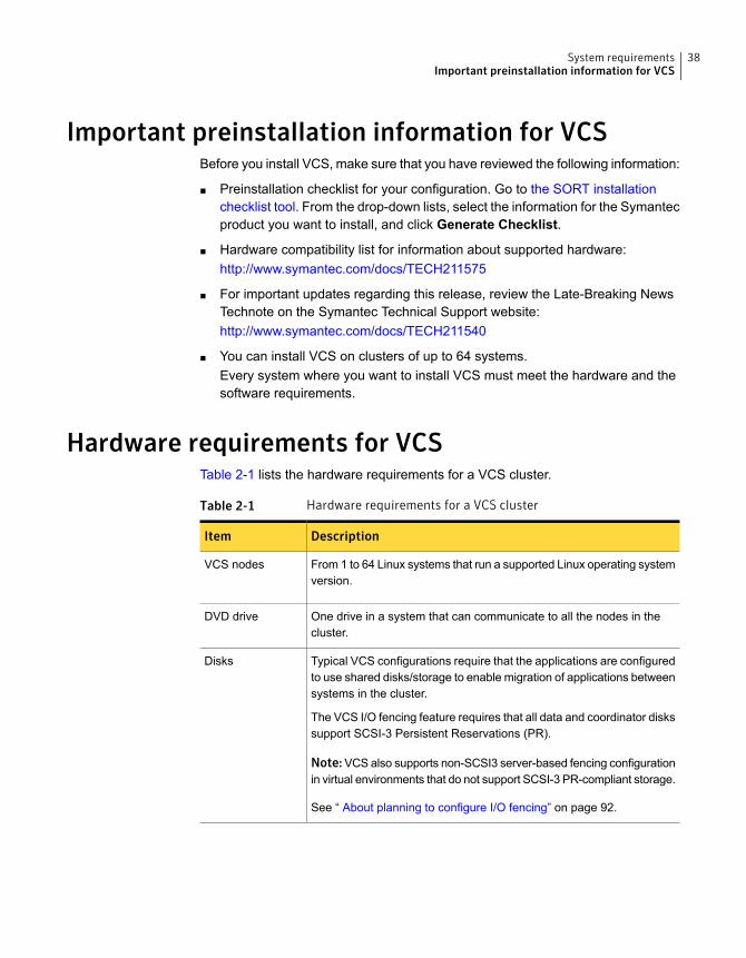
Hardware requirements for VCSTable 2-1 lists the hardware requirements for a VCS cluster.
Table 2-1 Hardware requirements for a VCS cluster
DescriptionItem
From 1 to 64 Linux systems that run a supported Linux operating systemversion.
VCS nodes
One drive in a system that can communicate to all the nodes in thecluster.
DVD drive
Typical VCS configurations require that the applications are configuredto use shared disks/storage to enable migration of applications betweensystems in the cluster.
The VCS I/O fencing feature requires that all data and coordinator diskssupport SCSI-3 Persistent Reservations (PR).
Note:VCS also supports non-SCSI3 server-based fencing configurationin virtual environments that do not support SCSI-3 PR-compliant storage.
See “ About planning to configure I/O fencing” on page 92.
Disks
38System requirementsImportant preinstallation information for VCS
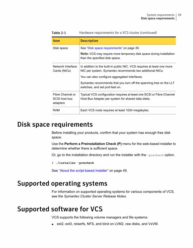
Table 2-1 Hardware requirements for a VCS cluster (continued)
DescriptionItem
See “Disk space requirements” on page 39.
Note: VCS may require more temporary disk space during installationthan the specified disk space.
Disk space
In addition to the built-in public NIC, VCS requires at least one moreNIC per system. Symantec recommends two additional NICs.
You can also configure aggregated interfaces.
Symantec recommends that you turn off the spanning tree on the LLTswitches, and set port-fast on.
Network InterfaceCards (NICs)
Typical VCS configuration requires at least one SCSI or Fibre ChannelHost Bus Adapter per system for shared data disks.
Fibre Channel orSCSI host busadapters
Each VCS node requires at least 1024 megabytes.RAM
Disk space requirementsBefore installing your products, confirm that your system has enough free diskspace.
Use the Perform a Preinstallation Check (P) menu for the web-based installer todetermine whether there is sufficient space.
Or, go to the installation directory and run the installer with the -precheck option.
# ./installer -precheck
See “About the script-based installer” on page 49.
Supported operating systemsFor information on supported operating systems for various components of VCS,see the Symantec Cluster Server Release Notes.
Supported software for VCSVCS supports the following volume managers and file systems:
■ ext2, ext3, reiserfs, NFS, and bind on LVM2, raw disks, and VxVM.
39System requirementsDisk space requirements
■ ext4 and xfs on LVM2 and raw disks
VCS supports the following versions of Symantec Storage Foundation:
Symantec Storage Foundation: Veritas Volume Manager (VxVM) with Veritas FileSystem (VxFS)
■ Storage Foundation 6.2
■ VxVM 6.2 with VxFS 6.2
■ Storage Foundation 6.1
■ VxVM 6.1 with VxFS 6.1
Note: VCS supports the previous and the next versions of Storage Foundation tofacilitate product upgrades.
For supported database versions of enterprise agents, refer the support matrix athttp://www.symantec.com/business/support/index?page=content&id=DOC4039.
I/O fencing requirementsDepending on whether you plan to configure disk-based fencing or server-basedfencing, make sure that you meet the requirements for coordination points:
■ Coordinator disksSee “Coordinator disk requirements for I/O fencing” on page 40.
■ CP serversSee “CP server requirements” on page 41.
To configure disk-based fencing or to configure server-based fencing with at leastone coordinator disk, make sure a version of Veritas Volume Manager (VxVM) thatsupports SCSI-3 persistent reservations (SCSI-3 PR) is installed on the VCS cluster.
See the Symantec Storage Foundation and High Availability Installation Guide.
If you have installed VCS in a virtual environment that is not SCSI-3 PR compliant,review the requirements to configure non-SCSI-3 fencing.
See “Non-SCSI-3 I/O fencing requirements” on page 44.
Coordinator disk requirements for I/O fencingMake sure that the I/O fencing coordinator disks meet the following requirements:
■ For disk-based I/O fencing, you must have at least three coordinator disks orthere must be odd number of coordinator disks.
40System requirementsI/O fencing requirements
■ The coordinator disks must be DMP devices.
■ Each of the coordinator disks must use a physically separate disk or LUN.Symantec recommends using the smallest possible LUNs for coordinator disks.
■ Each of the coordinator disks should exist on a different disk array, if possible.
■ The coordinator disks must support SCSI-3 persistent reservations.
■ Coordinator devices can be attached over iSCSI protocol but they must be DMPdevices and must support SCSI-3 persistent reservations.
■ Symantec recommends using hardware-based mirroring for coordinator disks.
■ Coordinator disks must not be used to store data or must not be included in diskgroups that store user data.
■ Coordinator disks cannot be the special devices that array vendors use. Forexample, you cannot use EMC gatekeeper devices as coordinator disks.
■ The coordinator disk size must be at least 128 MB.
CP server requirementsVCS 6.2 clusters (application clusters) support coordination point servers (CPservers) that are hosted on the following VCS and SFHA versions:
■ VCS 6.1 or later single-node cluster
■ SFHA 6.1 or later cluster
Upgrade considerations for CP servers
■ Upgrade VCS or SFHA on CP servers to version 6.2 if the current release versionis prior to version 6.1.
■ You do not need to upgrade CP servers to version 6.2 if the release version is6.1.
■ CP servers on version 6.2 support HTTPS-based communication with applicationclusters on version 6.1 or later.
■ CP servers on version 6.2 support IPM-based communication with applicationclusters on versions before 6.1.
■ You need to configure VIPs for HTTPS-based communication if release versionof application clusters is 6.1 or later.
■ You need to configure VIPs for IPM-based communication if release version ofapplication clusters is before 6.1.
Make sure that you meet the basic hardware requirements for the VCS/SFHA clusterto host the CP server.
41System requirementsI/O fencing requirements
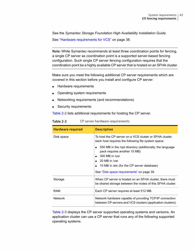
See the Symantec Storage Foundation High Availability Installation Guide.
See “Hardware requirements for VCS” on page 38.
Note: While Symantec recommends at least three coordination points for fencing,a single CP server as coordination point is a supported server-based fencingconfiguration. Such single CP server fencing configuration requires that thecoordination point be a highly available CP server that is hosted on an SFHA cluster.
Make sure you meet the following additional CP server requirements which arecovered in this section before you install and configure CP server:
■ Hardware requirements
■ Operating system requirements
■ Networking requirements (and recommendations)
■ Security requirements
Table 2-2 lists additional requirements for hosting the CP server.
Table 2-2 CP server hardware requirements
DescriptionHardware required
To host the CP server on a VCS cluster or SFHA cluster,each host requires the following file system space:
■ 550 MB in the /opt directory (additionally, the languagepack requires another 15 MB)
■ 300 MB in /usr■ 20 MB in /var■ 10 MB in /etc (for the CP server database)
See “Disk space requirements” on page 39.
Disk space
When CP server is hosted on an SFHA cluster, there mustbe shared storage between the nodes of this SFHA cluster.
Storage
Each CP server requires at least 512 MB.RAM
Network hardware capable of providing TCP/IP connectionbetween CP servers and VCS clusters (application clusters).
Network
Table 2-3 displays the CP server supported operating systems and versions. Anapplication cluster can use a CP server that runs any of the following supportedoperating systems.
42System requirementsI/O fencing requirements
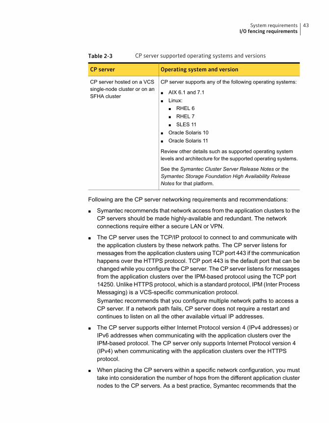
Table 2-3 CP server supported operating systems and versions
Operating system and versionCP server
CP server supports any of the following operating systems:
■ AIX 6.1 and 7.1■ Linux:
■ RHEL 6■ RHEL 7■ SLES 11
■ Oracle Solaris 10■ Oracle Solaris 11
Review other details such as supported operating systemlevels and architecture for the supported operating systems.
See the Symantec Cluster Server Release Notes or theSymantec Storage Foundation High Availability ReleaseNotes for that platform.
CP server hosted on a VCSsingle-node cluster or on anSFHA cluster
Following are the CP server networking requirements and recommendations:
■ Symantec recommends that network access from the application clusters to theCP servers should be made highly-available and redundant. The networkconnections require either a secure LAN or VPN.
■ The CP server uses the TCP/IP protocol to connect to and communicate withthe application clusters by these network paths. The CP server listens formessages from the application clusters using TCP port 443 if the communicationhappens over the HTTPS protocol. TCP port 443 is the default port that can bechanged while you configure the CP server. The CP server listens for messagesfrom the application clusters over the IPM-based protocol using the TCP port14250. Unlike HTTPS protocol, which is a standard protocol, IPM (Inter ProcessMessaging) is a VCS-specific communication protocol.Symantec recommends that you configure multiple network paths to access aCP server. If a network path fails, CP server does not require a restart andcontinues to listen on all the other available virtual IP addresses.
■ The CP server supports either Internet Protocol version 4 (IPv4 addresses) orIPv6 addresses when communicating with the application clusters over theIPM-based protocol. The CP server only supports Internet Protocol version 4(IPv4) when communicating with the application clusters over the HTTPSprotocol.
■ When placing the CP servers within a specific network configuration, you musttake into consideration the number of hops from the different application clusternodes to the CP servers. As a best practice, Symantec recommends that the
43System requirementsI/O fencing requirements
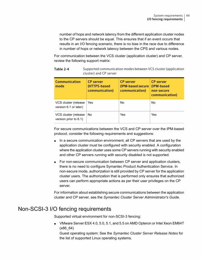
number of hops and network latency from the different application cluster nodesto the CP servers should be equal. This ensures that if an event occurs thatresults in an I/O fencing scenario, there is no bias in the race due to differencein number of hops or network latency between the CPS and various nodes.
For communication between the VCS cluster (application cluster) and CP server,review the following support matrix:
Table 2-4 Supported communication modes between VCS cluster (applicationcluster) and CP server
CP server(IPM-basednon-securecommunication)
CP server(IPM-basedsecurecommunication)
CP server(HTTPS-basedcommunication)
Communicationmode
NoNoYesVCS cluster (releaseversion 6.1 or later)
YesYesNoVCS cluster (releaseversion prior to 6.1)
For secure communications between the VCS and CP server over the IPM-basedprotocol, consider the following requirements and suggestions:
■ In a secure communication environment, all CP servers that are used by theapplication cluster must be configured with security enabled. A configurationwhere the application cluster uses some CP servers running with security enabledand other CP servers running with security disabled is not supported.
■ For non-secure communication between CP server and application clusters,there is no need to configure Symantec Product Authentication Service. Innon-secure mode, authorization is still provided by CP server for the applicationcluster users. The authorization that is performed only ensures that authorizedusers can perform appropriate actions as per their user privileges on the CPserver.
For information about establishing secure communications between the applicationcluster and CP server, see the Symantec Cluster Server Administrator's Guide.
Non-SCSI-3 I/O fencing requirementsSupported virtual environment for non-SCSI-3 fencing:
■ VMware Server ESX 4.0, 5.0, 5.1, and 5.5 on AMD Opteron or Intel Xeon EM64T(x86_64)Guest operating system: See the Symantec Cluster Server Release Notes forthe list of supported Linux operating systems.
44System requirementsI/O fencing requirements
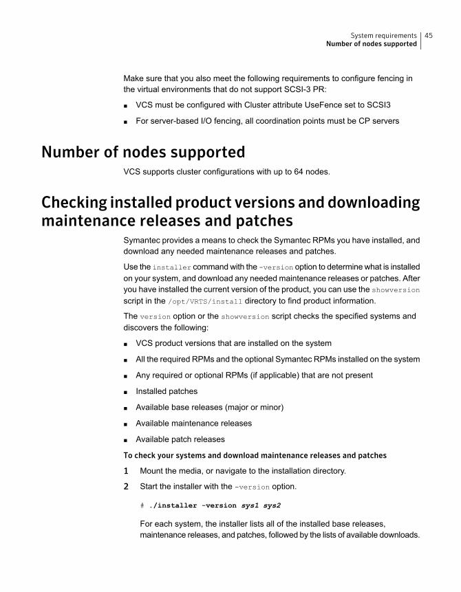
Make sure that you also meet the following requirements to configure fencing inthe virtual environments that do not support SCSI-3 PR:
■ VCS must be configured with Cluster attribute UseFence set to SCSI3
■ For server-based I/O fencing, all coordination points must be CP servers
Number of nodes supportedVCS supports cluster configurations with up to 64 nodes.
Checking installed product versions anddownloadingmaintenance releases and patches
Symantec provides a means to check the Symantec RPMs you have installed, anddownload any needed maintenance releases and patches.
Use the installer command with the -version option to determine what is installedon your system, and download any needed maintenance releases or patches. Afteryou have installed the current version of the product, you can use the showversion
script in the /opt/VRTS/install directory to find product information.
The version option or the showversion script checks the specified systems anddiscovers the following:
■ VCS product versions that are installed on the system
■ All the required RPMs and the optional Symantec RPMs installed on the system
■ Any required or optional RPMs (if applicable) that are not present
■ Installed patches
■ Available base releases (major or minor)
■ Available maintenance releases
■ Available patch releases
To check your systems and download maintenance releases and patches
1 Mount the media, or navigate to the installation directory.
2 Start the installer with the -version option.
# ./installer -version sys1 sys2
For each system, the installer lists all of the installed base releases,maintenance releases, and patches, followed by the lists of available downloads.
45System requirementsNumber of nodes supported
3 If you have Internet access, follow the prompts to download the availablemaintenance releases and patches to the local system.
4 If you do not have Internet access, you can download any needed maintenancereleases and patches from the Symantec Operations Readiness Tools (SORT)Patch Finder page at:
https://sort.symantec.com/patch/finder
You can obtain installer patches automatically or manually.
See “Obtaining installer patches” on page 46.
Downloading maintenance releases and patches requires the installer to makeoutbound networking calls. You can also disable external network connectionattempts.
See “Disabling external network connection attempts” on page 47.
Obtaining installer patchesSymantec occasionally finds issues with the Symantec Cluster Server installer, andposts public installer patches on the Symantec Operations Readiness Tools (SORT)website's Patch Finder page at:
https://sort.symantec.com/patch/finder
You can access installer patches automatically or manually.
To download installer patches automatically
◆ Starting with Symantec Cluster Server version 6.1, installer patches aredownloaded automatically. No action is needed on your part.
If you are running Symantec Cluster Server version 6.1 or later, and yoursystem has Internet access, the installer automatically imports any neededinstaller patch, and begins using it.
Automatically downloading installer patches requires the installer to make outboundnetworking calls. You can also disable external network connection attempts.
See “Disabling external network connection attempts” on page 47.
If your system does not have Internet access, you can download installer patchesmanually.
46System requirementsObtaining installer patches
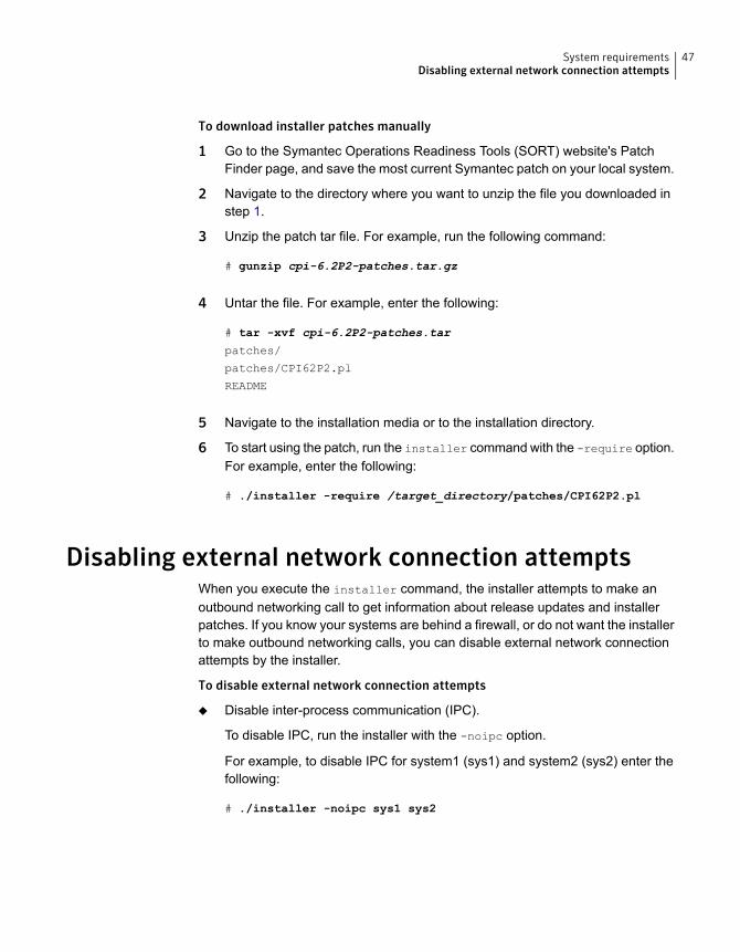
To download installer patches manually
1 Go to the Symantec Operations Readiness Tools (SORT) website's PatchFinder page, and save the most current Symantec patch on your local system.
2 Navigate to the directory where you want to unzip the file you downloaded instep 1.
3 Unzip the patch tar file. For example, run the following command:
# gunzip cpi-6.2P2-patches.tar.gz
4 Untar the file. For example, enter the following:
# tar -xvf cpi-6.2P2-patches.tar
patches/
patches/CPI62P2.pl
README
5 Navigate to the installation media or to the installation directory.
6 To start using the patch, run the installer command with the -require option.For example, enter the following:
# ./installer -require /target_directory/patches/CPI62P2.pl
Disabling external network connection attemptsWhen you execute the installer command, the installer attempts to make anoutbound networking call to get information about release updates and installerpatches. If you know your systems are behind a firewall, or do not want the installerto make outbound networking calls, you can disable external network connectionattempts by the installer.
To disable external network connection attempts
◆ Disable inter-process communication (IPC).
To disable IPC, run the installer with the -noipc option.
For example, to disable IPC for system1 (sys1) and system2 (sys2) enter thefollowing:
# ./installer -noipc sys1 sys2
47System requirementsDisabling external network connection attempts
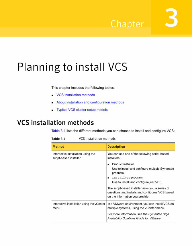
Planning to install VCS
This chapter includes the following topics:
■ VCS installation methods
■ About installation and configuration methods
■ Typical VCS cluster setup models
VCS installation methodsTable 3-1 lists the different methods you can choose to install and configure VCS:
Table 3-1 VCS installation methods
DescriptionMethod
You can use one of the following script-basedinstallers:
■ Product installerUse to install and configure multiple Symantecproducts.
■ installvcs programUse to install and configure just VCS.
The script-based installer asks you a series ofquestions and installs and configures VCS basedon the information you provide.
Interactive installation using thescript-based installer
In a VMware environment, you can install VCS onmultiple systems, using the vCenter menu.
For more information, see the Symantec HighAvailability Solutions Guide for VMware.
Interactive installation using the vCentermenu
3Chapter
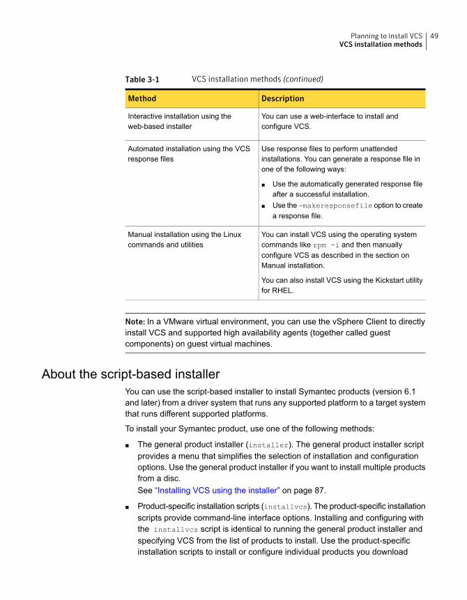
Table 3-1 VCS installation methods (continued)
DescriptionMethod
You can use a web-interface to install andconfigure VCS.
Interactive installation using theweb-based installer
Use response files to perform unattendedinstallations. You can generate a response file inone of the following ways:
■ Use the automatically generated response fileafter a successful installation.
■ Use the -makeresponsefile option to createa response file.
Automated installation using the VCSresponse files
You can install VCS using the operating systemcommands like rpm -i and then manuallyconfigure VCS as described in the section onManual installation.
You can also install VCS using the Kickstart utilityfor RHEL.
Manual installation using the Linuxcommands and utilities
Note: In a VMware virtual environment, you can use the vSphere Client to directlyinstall VCS and supported high availability agents (together called guestcomponents) on guest virtual machines.
About the script-based installerYou can use the script-based installer to install Symantec products (version 6.1and later) from a driver system that runs any supported platform to a target systemthat runs different supported platforms.
To install your Symantec product, use one of the following methods:
■ The general product installer (installer). The general product installer scriptprovides a menu that simplifies the selection of installation and configurationoptions. Use the general product installer if you want to install multiple productsfrom a disc.See “Installing VCS using the installer” on page 87.
■ Product-specific installation scripts (installvcs). The product-specific installationscripts provide command-line interface options. Installing and configuring withthe installvcs script is identical to running the general product installer andspecifying VCS from the list of products to install. Use the product-specificinstallation scripts to install or configure individual products you download
49Planning to install VCSVCS installation methods
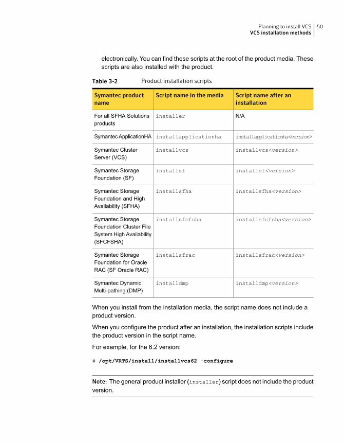
electronically. You can find these scripts at the root of the product media. Thesescripts are also installed with the product.
Table 3-2 Product installation scripts
Script name after aninstallation
Script name in the mediaSymantec productname
N/AinstallerFor all SFHA Solutionsproducts
installapplicationha<version>installapplicationhaSymantec ApplicationHA
installvcs<version>installvcsSymantec ClusterServer (VCS)
installsf<version>installsfSymantec StorageFoundation (SF)
installsfha<version>installsfhaSymantec StorageFoundation and HighAvailability (SFHA)
installsfcfsha<version>installsfcfshaSymantec StorageFoundation Cluster FileSystem High Availability(SFCFSHA)
installsfrac<version>installsfracSymantec StorageFoundation for OracleRAC (SF Oracle RAC)
installdmp<version>installdmpSymantec DynamicMulti-pathing (DMP)
When you install from the installation media, the script name does not include aproduct version.
When you configure the product after an installation, the installation scripts includethe product version in the script name.
For example, for the 6.2 version:
# /opt/VRTS/install/installvcs62 -configure
Note: The general product installer (installer) script does not include the productversion.
50Planning to install VCSVCS installation methods
At most points during the installation you can type the following characters fordifferent actions:
■ Use b (back) to return to a previous section of the installation procedure. Theback feature of the installation scripts is context-sensitive, so it returns to thebeginning of a grouped section of questions.
■ Use Ctrl+c to stop and exit the program if an installation procedure hangs.After a short delay, the script exits.
■ Use q to quit the installer.
■ Use ? to display help information.
■ Use the Enter button to accept a default response.
See “Installation script options” on page 494.
About the VCS installation programYou can access the installvcs program from the command line or through theproduct installer.
The VCS installation program is interactive and manages the following tasks:
■ Licensing VCS
■ Installing VCS RPMs on multiple cluster systems
■ Configuring VCS, by creating several detailed configuration files on each system
■ Starting VCS processes
You can choose to configure different optional features, such as the following:
■ SNMP and SMTP notification
■ VCS configuration in secure mode
■ The wide area Global Cluster Option feature
■ Cluster Virtual IP address
Review the highlights of the information for which installvcs prompts you as youproceed to configure.
See “About preparing to install VCS” on page 66.
The uninstallvcs, a companion to installvcs, uninstalls VCS RPMs.
See “Preparing to uninstall VCS” on page 473.
51Planning to install VCSVCS installation methods
Features of the script-based installerThe script-based installer supports installing, configuring, upgrading, and uninstallingVCS. In addition, the script-based installer also provides command options toperform the following tasks:
■ Check the systems for VCS installation requirements.See “Performing automated preinstallation check” on page 77.
■ Upgrade VCS if a previous version of VCS currently runs on a cluster.See “Upgrading VCS using the script-based installer” on page 362.
■ Start or stop VCS processesSee “Starting and stopping processes for the Symantec products ” on page 569.
■ Enable or disable a cluster to run in secure modeSee the Symantec Cluster Server Administrator's Guide.
■ Configure I/O fencing for the clusters to prevent data corruptionSee “Setting up disk-based I/O fencing using installvcs” on page 158.See “Setting up server-based I/O fencing using installvcs” on page 167.See “Setting up non-SCSI-3 I/O fencing in virtual environments using installvcs”on page 180.
■ Create a single-node clusterSee “Creating a single-node cluster using the installer program” on page 520.
■ Add a node to an existing clusterSee “Adding nodes using the VCS installer” on page 444.
■ Create a kickstart configuration file to install VCS using the Kickstart utility forRHEL.See “Installing VCS using Kickstart” on page 254.
■ Perform automated installations using the values that are stored in a configurationfile.See “Installing VCS using response files” on page 214.See “Configuring VCS using response files” on page 220.See “Upgrading VCS using response files” on page 390.
Interacting with the installvcsAs you run the program, you are prompted to answer yes or no questions. A set ofresponses that resemble [y, n, q, ?] (y) typically follow these questions. Theresponse within parentheses is the default, which you can select by pressing theEnter key. Enter the ? character to get help to answer the prompt. Enter q to quitthe installation.
52Planning to install VCSVCS installation methods
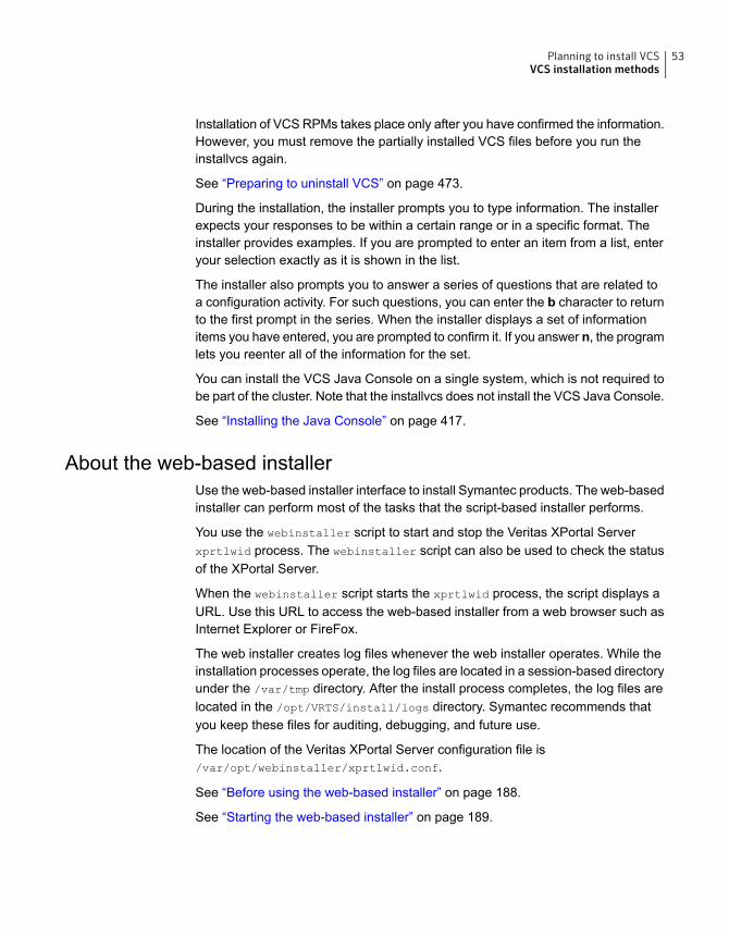
Installation of VCS RPMs takes place only after you have confirmed the information.However, you must remove the partially installed VCS files before you run theinstallvcs again.
See “Preparing to uninstall VCS” on page 473.
During the installation, the installer prompts you to type information. The installerexpects your responses to be within a certain range or in a specific format. Theinstaller provides examples. If you are prompted to enter an item from a list, enteryour selection exactly as it is shown in the list.
The installer also prompts you to answer a series of questions that are related toa configuration activity. For such questions, you can enter the b character to returnto the first prompt in the series. When the installer displays a set of informationitems you have entered, you are prompted to confirm it. If you answer n, the programlets you reenter all of the information for the set.
You can install the VCS Java Console on a single system, which is not required tobe part of the cluster. Note that the installvcs does not install the VCS Java Console.
See “Installing the Java Console” on page 417.
About the web-based installerUse the web-based installer interface to install Symantec products. The web-basedinstaller can perform most of the tasks that the script-based installer performs.
You use the webinstaller script to start and stop the Veritas XPortal Serverxprtlwid process. The webinstaller script can also be used to check the statusof the XPortal Server.
When the webinstaller script starts the xprtlwid process, the script displays aURL. Use this URL to access the web-based installer from a web browser such asInternet Explorer or FireFox.
The web installer creates log files whenever the web installer operates. While theinstallation processes operate, the log files are located in a session-based directoryunder the /var/tmp directory. After the install process completes, the log files arelocated in the /opt/VRTS/install/logs directory. Symantec recommends thatyou keep these files for auditing, debugging, and future use.
The location of the Veritas XPortal Server configuration file is/var/opt/webinstaller/xprtlwid.conf.
See “Before using the web-based installer” on page 188.
See “Starting the web-based installer” on page 189.
53Planning to install VCSVCS installation methods
About response filesThe installer generates a "response file" after performing an installer task such asinstallation, configuration, uninstallation, or upgrade. These response files containthe details that you provided to the installer questions in the form of values for theresponse file variables. The response file also contains descriptions and explanationsof the variables and their values.
You can also create a response file using the -makeresponsefile option of theinstaller.
The installer displays the location of the response file at the end of each successfulinstaller task. The installer saves the response file in the default location for theinstall-related log files: /opt/VRTS/install/logs. If you provided a different log pathusing the -logpath option, the installer saves the response file in the path that youspecified.
The format of the response file name is:/opt/VRTS/install/logs/installscript-YYYYMMDDHHSSxxx/installscript-YYYYMMDDHHSSxxx.response, where:
■ installscript may be, for example: installer, webinstaller, installvcs, or uninstallvcs
■ YYYYMMDDHHSS is the current date when the installscript is run and xxx arethree random letters that the script generates for an installation instance
For example:/opt/VRTS/install/logs/installer-200910101010ldS/installer-200910101010ldS.response
You can customize the response file as required to perform unattended installationsusing the -responsefile option of the installer. This method of automatedinstallations is useful in the following cases:
■ To perform multiple installations to set up a large VCS cluster.See “Installing VCS using response files” on page 214.
■ To upgrade VCS on multiple systems in a large VCS cluster.See “Upgrading VCS using response files” on page 390.
■ To uninstall VCS from multiple systems in a large VCS cluster.See “Uninstalling VCS using response files” on page 479.
Syntax in the response fileThe syntax of the Perl statements that is included in the response file variablesvaries. It can depend on whether the variables require scalar or list values.
For example, in the case of a string value:
$CFG{Scalar_variable}="value";
54Planning to install VCSVCS installation methods

or, in the case of an integer value:
$CFG{Scalar_variable}=123;
or, in the case of a list:
$CFG{List_variable}=["value 1 ", "value 2 ", "value 3 "];
About installation and configuration methodsYou can install and configure VCS using Symantec installation programs or usingnative operating system methods.
Note: In a VMware virtual environment, you can use the vSphere Client to installVCS and supported high availability agents (together called guest components) onthe guest virtual machines. See the Symantec High Availability Solution Guide forVMware for the installation details.
Table 3-3 shows the installation and configuration methods that VCS supports.
55Planning to install VCSAbout installation and configuration methods

Table 3-3 Installation and configuration methods
DescriptionMethod
Using the script-based installer, you can install Symantecproducts from a driver system running a supported platformto target computers running any supported platform.
To install your Symantec product using the installer, chooseone of the following:
■ The general product installer:installer
The general product installer script provides a menu thatsimplifies the selection of installation and configurationoptions. Use the general product installer if you want toinstall multiple products from a disc.
■ Product-specific installation scripts:installvcs<version>
The product-specific installation scripts providecommand-line interface options. Installing and configuringwith the installvcs script is identical to running thegeneral product installer and specifying VCS from the listof products to install.Use the product-specific installation scripts to install orconfigure individual products you download electronically.
See “About the script-based installer” on page 49.
The script-based installer
Using the web-based installer, you can install Symantecproducts from a driver system running a supported platformto target computers running any supported platform
The web-based installer provides an interface to managethe installation and configuration from a remote site using astandard web browser.
webinstaller
See “About the web-based installer” on page 53.
The web-based installer
Using the Deployment Server, you can store multiple releaseimages in one central location and deploy them to systemsof any supported platform.
See “About the Deployment Server” on page 318.
Deployment Server
56Planning to install VCSAbout installation and configuration methods
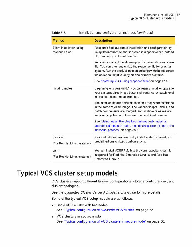
Table 3-3 Installation and configuration methods (continued)
DescriptionMethod
Response files automate installation and configuration byusing the information that is stored in a specified file insteadof prompting you for information.
You can use any of the above options to generate a responsefile. You can then customize the response file for anothersystem. Run the product installation script with the responsefile option to install silently on one or more systems.
See “Installing VCS using response files” on page 214.
Silent installation usingresponse files
Beginning with version 6.1, you can easily install or upgradeyour systems directly to a base, maintenance, or patch levelin one step using Install Bundles.
The installer installs both releases as if they were combinedin the same release image. The various scripts, RPMs, andpatch components are merged, and multiple releases areinstalled together as if they are one combined release.
See “Using Install Bundles to simultaneously install orupgrade full releases (base, maintenance, rolling patch), andindividual patches” on page 359.
Install Bundles
Kickstart lets you automatically install systems based onpredefined customized configurations.
Kickstart
(For RedHat Linux systems)
You can install VCSRPMs into the yum repository. yum issupported for Red Hat Enterprise Linux 6 and Red HatEnterprise Linux 7.
yum
(For RedHat Linux systems)
Typical VCS cluster setup modelsVCS clusters support different failover configurations, storage configurations, andcluster topologies.
See the Symantec Cluster Server Administrator's Guide for more details.
Some of the typical VCS setup models are as follows:
■ Basic VCS cluster with two nodesSee “Typical configuration of two-node VCS cluster” on page 58.
■ VCS clusters in secure modeSee “Typical configuration of VCS clusters in secure mode” on page 58.
57Planning to install VCSTypical VCS cluster setup models
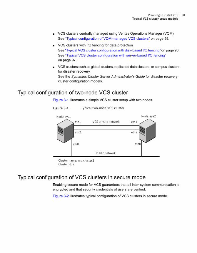
■ VCS clusters centrally managed using Veritas Operations Manager (VOM)See “Typical configuration of VOM-managed VCS clusters” on page 59.
■ VCS clusters with I/O fencing for data protectionSee “Typical VCS cluster configuration with disk-based I/O fencing” on page 96.See “Typical VCS cluster configuration with server-based I/O fencing”on page 97.
■ VCS clusters such as global clusters, replicated data clusters, or campus clustersfor disaster recoverySee the Symantec Cluster Server Administrator's Guide for disaster recoverycluster configuration models.
Typical configuration of two-node VCS clusterFigure 3-1 illustrates a simple VCS cluster setup with two nodes.
Figure 3-1 Typical two-node VCS cluster
Node: sys1
Cluster name: vcs_cluster2Cluster id: 7
VCS private network
Public network
eth1 eth1
eth2eth2
eth0 eth0
Node: sys2
Typical configuration of VCS clusters in secure modeEnabling secure mode for VCS guarantees that all inter-system communication isencrypted and that security credentials of users are verified.
Figure 3-2 illustrates typical configuration of VCS clusters in secure mode.
58Planning to install VCSTypical VCS cluster setup models
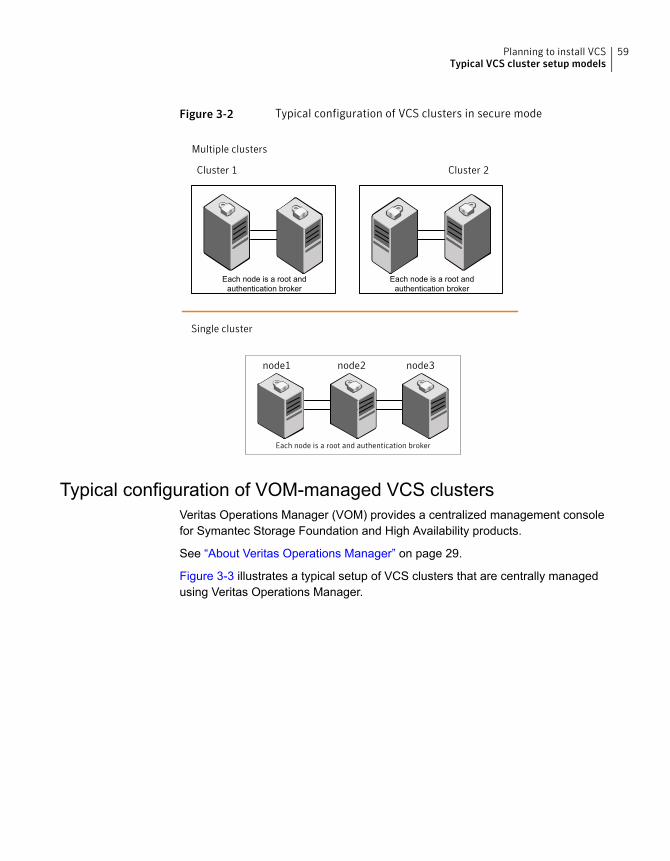
Figure 3-2 Typical configuration of VCS clusters in secure mode
Cluster 1 Cluster 2
node1 node2 node3
Multiple clusters
Single cluster
Each node is a root and authentication broker
Each node is a root andauthentication broker
Each node is a root andauthentication broker
Typical configuration of VOM-managed VCS clustersVeritas Operations Manager (VOM) provides a centralized management consolefor Symantec Storage Foundation and High Availability products.
See “About Veritas Operations Manager” on page 29.
Figure 3-3 illustrates a typical setup of VCS clusters that are centrally managedusing Veritas Operations Manager.
59Planning to install VCSTypical VCS cluster setup models
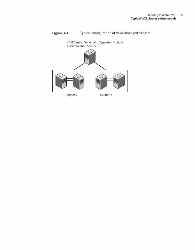
Figure 3-3 Typical configuration of VOM-managed clusters
Cluster 1 Cluster 2
VOM Central Server and Symantec ProductAuthentication Service
60Planning to install VCSTypical VCS cluster setup models
Licensing VCS
This chapter includes the following topics:
■ About Symantec product licensing
■ Obtaining VCS license keys
■ Installing Symantec product license keys
About Symantec product licensingYou have the option to install Symantec products without a license key. Installationwithout a license does not eliminate the need to obtain a license. A software licenseis a legal instrument governing the usage or redistribution of copyright protectedsoftware. The administrator and company representatives must ensure that a serveror cluster is entitled to the license level for the products installed. Symantec reservesthe right to ensure entitlement and compliance through auditing.
If you encounter problems while licensing this product, visit the Symantec licensingSupport website.
http://www.symantec.com/products-solutions/licensing/activating-software/detail.jsp?detail_id=licensing_portal
The product installer prompts you to select one of the following licensing methods:
■ Install a license key for the product and features that you want to install.When you purchase a Symantec product, you receive a License Key certificate.The certificate specifies the product keys and the number of product licensespurchased.
■ Continue to install without a license key.The installer prompts for the product modes and options that you want to install,and then sets the required product level.
4Chapter
Within 60 days of choosing this option, you must install a valid license keycorresponding to the license level entitled, or continue with keyless licensing bymanaging the systems with a management server. If you do not comply withthe above terms, continuing to use the Symantec product is a violation of yourEnd User License Agreement, and results in warning messagesFor more information about keyless licensing, see the following URL:http://go.symantec.com/sfhakeyless
If you upgrade to this release from a previous release of the Symantec software,the installer asks whether you want to upgrade the key to the new version. Theexisting license keys may not activate new features in this release.
If you upgrade with the product installer, or if you install or upgrade with a methodother than the product installer, you must do one of the following to license theproducts:
■ Run the vxkeyless command to set the product level for the products you havepurchased. This option also requires that you manage the server or cluster witha management server.See “Setting or changing the product level for keyless licensing” on page 251.See the vxkeyless(1m) manual page.
■ Use the vxlicinst command to install a valid product license key for theproducts you have purchased.See “Installing Symantec product license keys” on page 63.See the vxlicinst(1m) manual page.
You can also use the above options to change the product levels to another levelthat you are authorized to use. For example, you can add the replication option tothe installed product. You must ensure that you have the appropriate license forthe product level and options in use.
Note: To change from one product group to another, you may need to performadditional steps.
Obtaining VCS license keysThis product includes a License Key certificate. The certificate specifies the productkeys and the number of product licenses purchased. A single key lets you installthe product on the number and type of systems for which you purchased the license.A key may enable the operation of more products than are specified on thecertificate. However, you are legally limited to the number of product licensespurchased. The product installation procedure describes how to activate the key.
62Licensing VCSObtaining VCS license keys
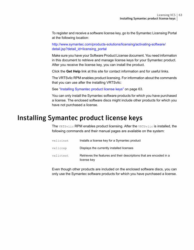
To register and receive a software license key, go to the Symantec Licensing Portalat the following location:
http://www.symantec.com/products-solutions/licensing/activating-software/detail.jsp?detail_id=licensing_portal
Make sure you have your Software Product License document. You need informationin this document to retrieve and manage license keys for your Symantec product.After you receive the license key, you can install the product.
Click the Get Help link at this site for contact information and for useful links.
The VRTSvlic RPM enables product licensing. For information about the commandsthat you can use after the installing VRTSvlic:
See “Installing Symantec product license keys” on page 63.
You can only install the Symantec software products for which you have purchaseda license. The enclosed software discs might include other products for which youhave not purchased a license.
Installing Symantec product license keysThe VRTSvlic RPM enables product licensing. After the VRTSvlic is installed, thefollowing commands and their manual pages are available on the system:
Installs a license key for a Symantec productvxlicinst
Displays the currently installed licensesvxlicrep
Retrieves the features and their descriptions that are encoded in alicense key
vxlictest
Even though other products are included on the enclosed software discs, you canonly use the Symantec software products for which you have purchased a license.
63Licensing VCSInstalling Symantec product license keys
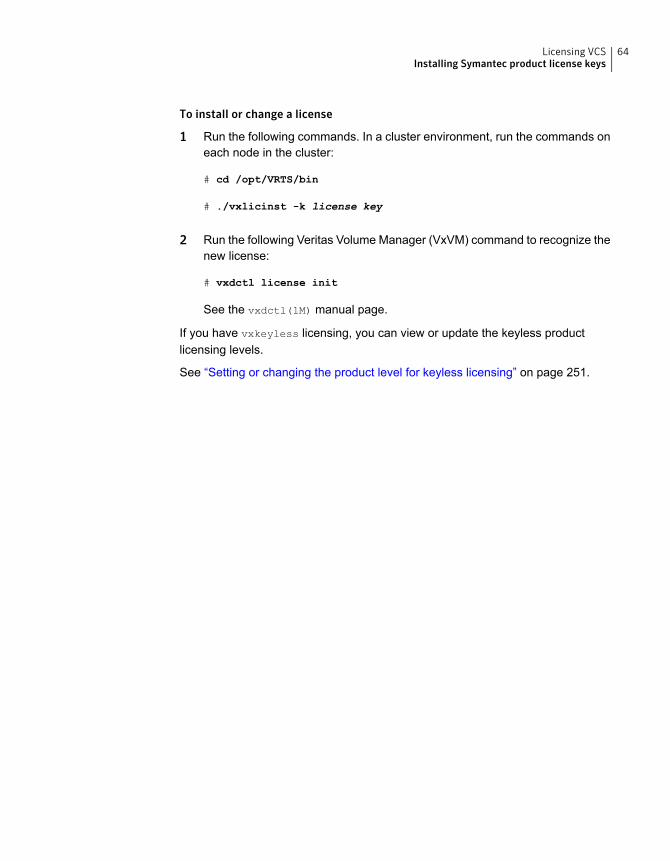
To install or change a license
1 Run the following commands. In a cluster environment, run the commands oneach node in the cluster:
# cd /opt/VRTS/bin
# ./vxlicinst -k license key
2 Run the following Veritas Volume Manager (VxVM) command to recognize thenew license:
# vxdctl license init
See the vxdctl(1M) manual page.
If you have vxkeyless licensing, you can view or update the keyless productlicensing levels.
See “Setting or changing the product level for keyless licensing” on page 251.
64Licensing VCSInstalling Symantec product license keys
Preinstallation tasks
■ Chapter 5. Preparing to install VCS
2Section
Preparing to install VCS
This chapter includes the following topics:
■ About preparing to install VCS
■ Performing preinstallation tasks
■ Getting your VCS installation and configuration information ready
About preparing to install VCSBefore you perform the preinstallation tasks, make sure you reviewed the installationrequirements, set up the basic hardware, and planned your VCS setup.
Performing preinstallation tasksTable 5-1 lists the tasks you must perform before proceeding to install VCS.
Table 5-1 Preinstallation tasks
ReferenceTask
See “Obtaining VCS license keys” on page 62.Obtain license keys if youdo not want to usekeyless licensing.
See “Setting up the private network” on page 67.Set up the privatenetwork.
See “Verifying network interfaces for persistent names”on page 70.
Configure persistentnetwork interfaces
See “About configuring secure shell or remote shellcommunication modes before installing products” on page 557.
Enable communicationbetween systems.
5Chapter
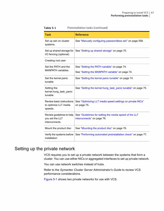
Table 5-1 Preinstallation tasks (continued)
ReferenceTask
See “Manually configuring passwordless ssh” on page 558.Set up ssh on clustersystems.
See “Setting up shared storage” on page 70.Set up shared storage forI/O fencing (optional)
Creating root user
See “Setting the PATH variable” on page 74.
See “Setting the MANPATH variable” on page 74.
Set the PATH and theMANPATH variables.
See “Setting the kernel.panic tunable” on page 74.Set the kernel.panictunable
See “Setting the kernel.hung_task_panic tunable” on page 75.Setting thekernel.hung_task_panictunable
See “Optimizing LLT media speed settings on private NICs”on page 75.
Review basic instructionsto optimize LLT mediaspeeds.
See “Guidelines for setting the media speed of the LLTinterconnects” on page 76.
Review guidelines to helpyou set the LLTinterconnects.
See “Mounting the product disc” on page 76.Mount the product disc
See “Performing automated preinstallation check” on page 77.Verify the systems beforeinstallation
Setting up the private networkVCS requires you to set up a private network between the systems that form acluster. You can use either NICs or aggregated interfaces to set up private network.
You can use network switches instead of hubs.
Refer to the Symantec Cluster Server Administrator's Guide to review VCSperformance considerations.
Figure 5-1 shows two private networks for use with VCS.
67Preparing to install VCSPerforming preinstallation tasks
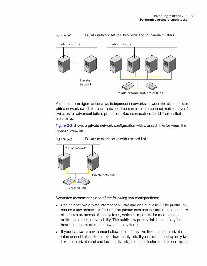
Figure 5-1 Private network setups: two-node and four-node clusters
Public network Public network
Privatenetwork
Private network switches or hubs
You need to configure at least two independent networks between the cluster nodeswith a network switch for each network. You can also interconnect multiple layer 2switches for advanced failure protection. Such connections for LLT are calledcross-links.
Figure 5-2 shows a private network configuration with crossed links between thenetwork switches.
Figure 5-2 Private network setup with crossed links
Crossed link
Public network
Private networks
Symantec recommends one of the following two configurations:
■ Use at least two private interconnect links and one public link. The public linkcan be a low priority link for LLT. The private interconnect link is used to sharecluster status across all the systems, which is important for membershiparbitration and high availability. The public low priority link is used only forheartbeat communication between the systems.
■ If your hardware environment allows use of only two links, use one privateinterconnect link and one public low priority link. If you decide to set up only twolinks (one private and one low priority link), then the cluster must be configured
68Preparing to install VCSPerforming preinstallation tasks
to use I/O fencing, either disk-based or server-based fencing configuration. Withonly two links, if one system goes down, I/O fencing ensures that other systemcan take over the service groups and shared file systems from the failed node.
To set up the private network
1 Install the required network interface cards (NICs).
Create aggregated interfaces if you want to use these to set up private network.
2 Connect the VCS private NICs on each system.
3 Use crossover Ethernet cables, switches, or independent hubs for each VCScommunication network. Note that the crossover Ethernet cables are supportedonly on two systems.
Ensure that you meet the following requirements:
■ The power to the switches or hubs must come from separate sources.
■ On each system, you must use two independent network cards to provideredundancy.
■ If a network interface is part of an aggregated interface, you must notconfigure the network interface under LLT. However, you can configure theaggregated interface under LLT.
■ When you configure Ethernet switches for LLT private interconnect, disablethe spanning tree algorithm on the ports used for the interconnect.
During the process of setting up heartbeat connections, consider a case wherea failure removes all communications between the systems.
Note that a chance for data corruption exists under the following conditions:
■ The systems still run, and
■ The systems can access the shared storage.
4 Test the network connections. Temporarily assign network addresses and usetelnet or ping to verify communications.
LLT uses its own protocol, and does not use TCP/IP. So, you must ensure thatthe private network connections are used only for LLT communication and notfor TCP/IP traffic. To verify this requirement, unplumb and unconfigure anytemporary IP addresses that are configured on the network interfaces.
The installer configures the private network in the cluster during configuration.
You can also manually configure LLT.
See “Configuring LLT manually” on page 267.
69Preparing to install VCSPerforming preinstallation tasks

Verifying network interfaces for persistent namesSymantec Cluster Server requires that the network interface cards use persistentinterface names. By default, SLES 10, RHEL5, and later Linux flavors use udev toachieve persistent interface names.
To verify and configure persistent network interfaces
◆ Make sure that the network interface names are persistent.
If the network interface names are not persistent, then manually configurepersistent interfaces.
For RHEL, SLES, and OL, refer to the OS documentation for information onconfiguring persistent interfaces.
About using ssh or rsh with the installerThe installer uses passwordless Secure Shell (ssh) or Remote Shell (rsh)communications among systems. The installer uses the ssh daemon or rsh daemonthat comes bundled with the operating system. During an installation, you choosethe communication method that you want to use. Or, you can run the installer
-comsetup command to set up ssh or rsh explicitly. You then provide the installerwith the superuser passwords for the systems where you plan to install. When theinstallation process completes, the installer asks you if you want to remove thepassword-less connection. If installation terminated abruptly, use the installationscript's -comcleanup option to remove the ssh configuration or rsh configurationfrom the systems.
See “Installation script options” on page 494.
In most installation, configuration, upgrade (where necessary), and uninstallationscenarios, the installer can configure ssh or rsh on the target systems. In thefollowing scenarios, you need to set up ssh or rsh manually, or use the installer
-comsetup option to set up an ssh or rsh configuration from the systems.
■ When you perform installer sessions using a response file.
See “About configuring secure shell or remote shell communication modes beforeinstalling products” on page 557.
Setting up shared storageThe following sections describe how to set up the SCSI and the Fibre Channeldevices that the cluster systems share.
70Preparing to install VCSPerforming preinstallation tasks
For I/O fencing, the data disks must support SCSI-3 persistent reservations. Youneed to configure a coordinator disk group that supports SCSI-3 PR and verify thatit works.
Note: VCS also supports non-SCSI3 server-based fencing configuration in virtualenvironments that do not support SCSI-3 PR-compliant storage.
See “ About planning to configure I/O fencing” on page 92.
See also the Symantec Cluster Server Administrator's Guide for a description ofI/O fencing.
Setting up shared storage: SCSIPerform the following steps to set up shared storage.
To set up shared storage
1 Connect the disk to the first cluster system.
2 Power on the disk.
3 Connect a terminator to the other port of the disk.
4 Boot the system. The disk is detected while the system boots.
5 Press CTRL+A to bring up the SCSI BIOS settings for that disk.
Set the following:
■ Set Host adapter SCSI ID = 7, or to an appropriate value for yourconfiguration.
■ Set Host Adapter BIOS in Advanced Configuration Options to Disabled.
6 Format the shared disk and create required partitions on it.
Perform the following:
■ Identify your shared disk name. If you have two internal SCSI hard disks,your shared disk is /dev/sdc.Identify whether the shared disk is sdc, sdb, and so on.
■ Type the following command:
# fdisk /dev/shareddiskname
For example, if your shared disk is sdc, type:
# fdisk /dev/sdc
■ Create disk groups and volumes using Volume Manager utilities.
71Preparing to install VCSPerforming preinstallation tasks
■ To apply a file system on the volumes, type:
# mkfs -t fs-type /dev/vx/dsk/disk-group/volume
For example, enter the following command:
# mkfs -t vxfs /dev/vx/dsk/dg/vol01
Where the name of the disk group is dg, the name of the volume is vol01,and the file system type is vxfs.
7 Power off the disk.
8 Remove the terminator from the disk and connect the disk to the other clustersystem.
9 Power on the disk.
10 Boot the second system. The system can now detect the disk.
11 Press Ctrl+A to bring up the SCSI BIOS settings for the disk.
Set the following:
■ Set Host adapter SCSI ID = 6, or to an appropriate value for yourconfiguration. Note that the SCSI ID should be different from the oneconfigured on the first cluster system.
■ Set Host Adapter BIOS in Advanced Configuration Options to Disabled.
12 Verify that you can view the shared disk using the fdisk command.
Setting up shared storage: Fibre ChannelPerform the following steps to set up Fibre Channel.
To set up shared storage for Fibre Channel
1 Connect the Fibre Channel disk to a cluster system.
2 Boot the system and change the settings of the Fibre Channel. Perform thefollowing tasks for all QLogic adapters in the system:
■ Press Alt+Q to bring up the QLogic adapter settings menu.
■ Choose Configuration Settings.
■ Click Enter.
■ Choose Advanced Adapter Settings.
■ Click Enter.
■ Set the Enable Target Reset option to Yes (the default value).
72Preparing to install VCSPerforming preinstallation tasks
■ Save the configuration.
■ Reboot the system.
3 Verify that the system detects the Fibre Channel disks properly.
4 Create volumes. Format the shared disk and create required partitions on itand perform the following:
■ Identify your shared disk name. If you have two internal SCSI hard disks,your shared disk is /dev/sdc.Identify whether the shared disk is sdc, sdb, and so on.
■ Type the following command:
# fdisk /dev/shareddiskname
For example, if your shared disk is sdc, type:
# fdisk /dev/sdc
■ Create disk groups and volumes using Volume Manager utilities.
■ To apply a file system on the volumes, type:
# mkfs -t fs-type /dev/vx/rdsk/disk-group/volume
For example, enter the following command:
# mkfs -t vxfs /dev/vx/rdsk/dg/vol01
Where the name of the disk group is dg, the name of the volume is vol01,and the file system type is vxfs.
5 Repeat step 2 and step 3 for all nodes in the clusters that require connectionswith Fibre Channel.
6 Power off this cluster system.
7 Connect the same disks to the next cluster system.
8 Turn on the power for the second system.
9 Verify that the second system can see the disk names correctly—the disknames should be the same.
See “Verifying that the nodes have access to the same disk” on page 165.
73Preparing to install VCSPerforming preinstallation tasks
Setting the PATH variableTo set the PATH variable
◆ Do one of the following:
■ For the Bourne Shell (sh), Bourne-again Shell (bash), or Korn shell (ksh),type:
# PATH=/opt/VRTS/bin:$PATH; export $PATH
■ For the C Shell (csh) or enhanced C Shell (tcsh), type:
# setenv PATH :/opt/VRTS/bin:$PATH
Setting the MANPATH variableSet the MANPATH variable to view the manual pages.
To set the MANPATH variable
◆ Do one of the following:
■ For the Bourne Shell (sh), Bourne-again Shell (bash), or Korn shell (ksh),type:
# MANPATH=/opt/VRTS/man:$MANPATH; export MANPATH
■ For the C Shell (csh) or enhanced C Shell (tcsh), type:
% setenv MANPATH /usr/share/man:/opt/VRTS/man
If you use the man command to access manual pages, set LC_ALL to "C" inyour shell for correct page display.
# export LC_ALL=C
See incident 82099 on the Red Hat support web site for more information.
Setting the kernel.panic tunableBy default, the kernel.panic tunable is set to zero. Therefore the kernel does notrestart automatically if a node panics. To ensure that the node restarts automaticallyafter it panics, this tunable must be set to a non-zero value.
74Preparing to install VCSPerforming preinstallation tasks

To set the kernel.panic tunable
1 Set the kernel.panic tunable to a desired value in the /etc/sysctl.conf file.
For example, kernel.panic = 10, will assign a value 10 seconds to thekernel.panic tunable. This step makes the change persistent across restarts.
2 Run the command:
sysctl -w kernel.panic=10
In case of a panic, the node will restart after 10 seconds.
Setting the kernel.hung_task_panic tunableBy default, in the Linux kernel the kernel.hung_task_panic tunable is enabledand the kernel.hung_task_timeout_secs tunable is set to a default non-zerovalue.
To ensure that the node does not panic, the kernel.hung_task_panic tunablemust be disabled. If kernel.hung_task_panic is enabled, then it causes the kernelto panic when any of the following kernel threads waits for more than thekernel.hung_task_timeout_secs value:
■ The vxfenconfig thread in the vxfen configuration path waits for GAB to seed.
■ The vxfenswap thread in the online coordinator disks replacement path waitsfor the snapshot of peer nodes of the new coordinator disks.
To disable the kernel.hung_task_panic tunable:
■ Set the kernel.hung_task_panic tunable to zero (0) in the /etc/sysctl.conf
file. This step ensures that the change is persistent across node restarts.
■ Run the command on each node.# sysctl -w kernel.hung_task_panic=0
To verify the kernel.hung_task_panic tunable value, run the following command:
■ # sysctl -a | grep hung_task_panic
Optimizing LLT media speed settings on private NICsFor optimal LLT communication among the cluster nodes, the interface cards oneach node must use the same media speed settings. Also, the settings for theswitches or the hubs that are used for the LLT interconnections must match that ofthe interface cards. Incorrect settings can cause poor network performance or evennetwork failure.
75Preparing to install VCSPerforming preinstallation tasks
If you use different media speed for the private NICs, Symantec recommends thatyou configure the NICs with lesser speed as low-priority links to enhance LLTperformance.
Guidelines for setting the media speed of the LLT interconnectsReview the following guidelines for setting the media speed of the LLT interconnects:
■ Symantec recommends that you manually set the same media speed settingon each Ethernet card on each node.If you use different media speed for the private NICs, Symantec recommendsthat you configure the NICs with lesser speed as low-priority links to enhanceLLT performance.
■ If you have hubs or switches for LLT interconnects, then set the hub or switchport to the same setting as used on the cards on each node.
■ If you use directly connected Ethernet links (using crossover cables), Symantecrecommends that you set the media speed to the highest value common to bothcards, typically 1000_Full_Duplex.
Details for setting the media speeds for specific devices are outside of the scopeof this manual. Consult the device’s documentation or the operating system manualfor more information.
VCS considerations for Blade server environmentsTypically, a server in the Blade environment has only two NICs. The followingconsiderations need to be observed while configuring VCS in Blade environmentin private networks:
■ If your heartbeat links do not use TCP/IP and are not routable, you must useseparate and dedicated physical networks. This will guard against inadvertentsplit brains due to inappropriate routing configurations.
■ Out of the two heartbeat links, one must be dedicated and the other can be alow-priority heartbeat shared on the public IP NIC. It is assumed that the twonodes in the cluster have public IPs on the same subnet and wire.
■ The size each packet of traffic on the public NIC must be 64 bytes/second andmust not interfere with the public traffic.
Mounting the product discYou must have superuser (root) privileges to load the VCS software.
76Preparing to install VCSPerforming preinstallation tasks
To mount the product disc
1 Log in as superuser on a system where you want to install VCS.
The system from which you install VCS does not need to be part of the cluster.The systems must be in the same subnet.
2 Insert the product disc with the VCS software into a drive that is connected tothe system.
The disc is automatically mounted.
3 If the disc does not automatically mount, then enter:
# mount -t iso9660 /dev/sr0 /media
4 Navigate to the location of the RPMs.
# cd /mnt/cdrom/dist_arch/rpms
Where dist is rhel6, rhel7 or sles11, and arch is x86_64 for RHEL and SLES.
Performing automated preinstallation checkBefore you begin the installation of VCS software, you can check the readiness ofthe systems where you plan to install VCS. The command to start the preinstallationcheck is:
installvcs -precheck system1 system2 ...
You can also run the installer -precheck command.
See “About Symantec Operations Readiness Tools” on page 30.
77Preparing to install VCSPerforming preinstallation tasks
To check the systems
1 Navigate to the folder that contains the installvcs.
# cd /cdrom/dist_arch/cluster_server
Where dist is rhel6, rhel7 or sles11, and arch is x86_64 for RHEL and SLES.
See “Mounting the product disc” on page 76.
2 Start the preinstallation check:
# ./installvcs -precheck sys1 sys2
The program proceeds in a noninteractive mode to examine the systems forlicenses, RPMs, disk space, and system-to-system communications.
3 Review the output as the program displays the results of the check and savesthe results of the check in a log file.
Reformatting VCS configuration files on a stopped clusterWhen you manually edit VCS configuration files (for example, the main.cf or types.cffile) you can potentially create formatting issues that may cause the installer tointerpret the cluster configuration information incorrectly.
If you have manually edited any of the configuration files, you need to perform oneof the following before you run the installation program:
■ On a running cluster, perform an haconf -dump command. This command savesthe configuration files and ensures that they do not have formatting errors beforeyou run the installer.
■ On cluster that is not running, perform the hacf -cftocmd and then the hacf
-cmdtocf commands to format the configuration files.
Note: Remember to make back up copies of the configuration files before you editthem.
You also need to use this procedure if you have manually changed the configurationfiles before you perform the following actions using the installer:
■ Upgrade VCS
■ Uninstall VCS
For more information about the main.cf and types.cf files, refer to the SymantecCluster Server Administrator's Guide.
78Preparing to install VCSPerforming preinstallation tasks
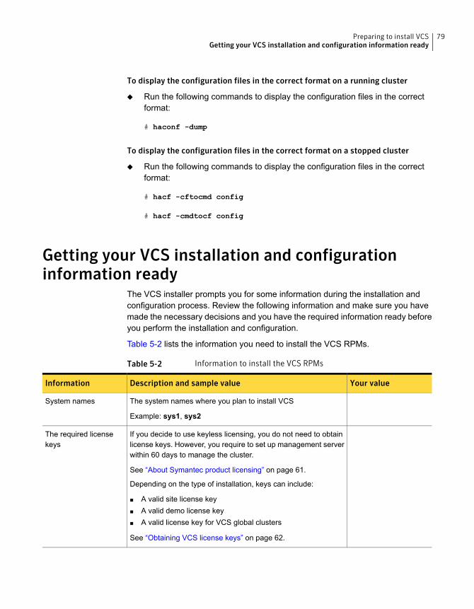
To display the configuration files in the correct format on a running cluster
◆ Run the following commands to display the configuration files in the correctformat:
# haconf -dump
To display the configuration files in the correct format on a stopped cluster
◆ Run the following commands to display the configuration files in the correctformat:
# hacf -cftocmd config
# hacf -cmdtocf config
Getting your VCS installation and configurationinformation ready
The VCS installer prompts you for some information during the installation andconfiguration process. Review the following information and make sure you havemade the necessary decisions and you have the required information ready beforeyou perform the installation and configuration.
Table 5-2 lists the information you need to install the VCS RPMs.
Table 5-2 Information to install the VCS RPMs
Your valueDescription and sample valueInformation
The system names where you plan to install VCS
Example: sys1, sys2
System names
If you decide to use keyless licensing, you do not need to obtainlicense keys. However, you require to set up management serverwithin 60 days to manage the cluster.
See “About Symantec product licensing” on page 61.
Depending on the type of installation, keys can include:
■ A valid site license key■ A valid demo license key■ A valid license key for VCS global clusters
See “Obtaining VCS license keys” on page 62.
The required licensekeys
79Preparing to install VCSGetting your VCS installation and configuration information ready
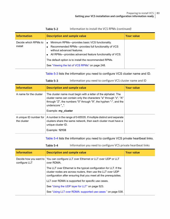
Table 5-2 Information to install the VCS RPMs (continued)
Your valueDescription and sample valueInformation
■ Minimum RPMs—provides basic VCS functionality.■ Recommended RPMs—provides full functionality of VCS
without advanced features.■ All RPMs—provides advanced feature functionality of VCS.
The default option is to install the recommended RPMs.
See “Viewing the list of VCS RPMs” on page 248.
Decide which RPMs toinstall
Table 5-3 lists the information you need to configure VCS cluster name and ID.
Table 5-3 Information you need to configure VCS cluster name and ID
Your valueDescription and sample valueInformation
The cluster name must begin with a letter of the alphabet. Thecluster name can contain only the characters "a" through "z", "A"through "Z", the numbers "0" through "9", the hyphen "-", and theunderscore "_".
Example: my_cluster
A name for the cluster
A number in the range of 0-65535. If multiple distinct and separateclusters share the same network, then each cluster must have aunique cluster ID.
Example: 12133
A unique ID number forthe cluster
Table 5-4 lists the information you need to configure VCS private heartbeat links.
Table 5-4 Information you need to configure VCS private heartbeat links
Your valueDescription and sample valueInformation
You can configure LLT over Ethernet or LLT over UDP or LLTover RDMA.
The LLT over Ethernet is the typical configuration for LLT. If thecluster nodes are across routers, then use the LLT over UDPconfiguration after ensuring that you meet all the prerequisites.
LLT over RDMA is supported for specific use cases.
See “Using the UDP layer for LLT” on page 523.
See “Using LLT over RDMA: supported use cases ” on page 538.
Decide how you want toconfigure LLT
80Preparing to install VCSGetting your VCS installation and configuration information ready
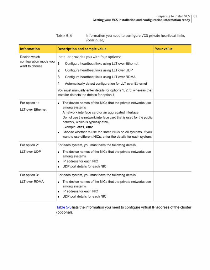
Table 5-4 Information you need to configure VCS private heartbeat links(continued)
Your valueDescription and sample valueInformation
Installer provides you with four options:
1 Configure heartbeat links using LLT over Ethernet
2 Configure heartbeat links using LLT over UDP
3 Configure heartbeat links using LLT over RDMA
4 Automatically detect configuration for LLT over Ethernet
You must manually enter details for options 1, 2, 3, whereas theinstaller detects the details for option 4.
Decide whichconfiguration mode youwant to choose
■ The device names of the NICs that the private networks useamong systemsA network interface card or an aggregated interface.Do not use the network interface card that is used for the publicnetwork, which is typically eth0.Example: eth1, eth2
■ Choose whether to use the same NICs on all systems. If youwant to use different NICs, enter the details for each system.
For option 1:
LLT over Ethernet
For each system, you must have the following details:
■ The device names of the NICs that the private networks useamong systems
■ IP address for each NIC■ UDP port details for each NIC
For option 2:
LLT over UDP
For each system, you must have the following details:
■ The device names of the NICs that the private networks useamong systems
■ IP address for each NIC■ UDP port details for each NIC
For option 3:
LLT over RDMA
Table 5-5 lists the information you need to configure virtual IP address of the cluster(optional).
81Preparing to install VCSGetting your VCS installation and configuration information ready
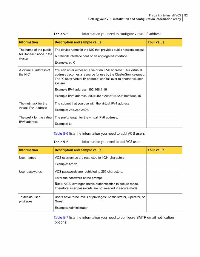
Table 5-5 Information you need to configure virtual IP address
Your valueDescription and sample valueInformation
The device name for the NIC that provides public network access.
A network interface card or an aggregated interface.
Example: eth0
The name of the publicNIC for each node in thecluster
You can enter either an IPv4 or an IPv6 address. This virtual IPaddress becomes a resource for use by the ClusterService group.The "Cluster Virtual IP address" can fail over to another clustersystem.
Example IPv4 address: 192.168.1.16
Example IPv6 address: 2001:454e:205a:110:203:baff:feee:10
A virtual IP address ofthe NIC
The subnet that you use with the virtual IPv4 address.
Example: 255.255.240.0
The netmask for thevirtual IPv4 address
The prefix length for the virtual IPv6 address.
Example: 64
The prefix for the virtualIPv6 address
Table 5-6 lists the information you need to add VCS users.
Table 5-6 Information you need to add VCS users
Your valueDescription and sample valueInformation
VCS usernames are restricted to 1024 characters.
Example: smith
User names
VCS passwords are restricted to 255 characters.
Enter the password at the prompt.
Note: VCS leverages native authentication in secure mode.Therefore, user passwords are not needed in secure mode.
User passwords
Users have three levels of privileges: Administrator, Operator, orGuest.
Example: Administrator
To decide userprivileges
Table 5-7 lists the information you need to configure SMTP email notification(optional).
82Preparing to install VCSGetting your VCS installation and configuration information ready
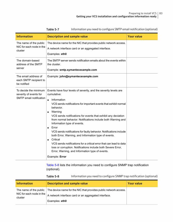
Table 5-7 Information you need to configure SMTP email notification (optional)
Your valueDescription and sample valueInformation
The device name for the NIC that provides public network access.
A network interface card or an aggregated interface.
Examples: eth0
The name of the publicNIC for each node in thecluster
The SMTP server sends notification emails about the events withinthe cluster.
Example: smtp.symantecexample.com
The domain-basedaddress of the SMTPserver
Example: [email protected] email address ofeach SMTP recipient tobe notified
Events have four levels of severity, and the severity levels arecumulative:
■ InformationVCS sends notifications for important events that exhibit normalbehavior.
■ WarningVCS sends notifications for events that exhibit any deviationfrom normal behavior. Notifications include both Warning andInformation type of events.
■ ErrorVCS sends notifications for faulty behavior. Notifications includeboth Error, Warning, and Information type of events.
■ CriticalVCS sends notifications for a critical error that can lead to dataloss or corruption. Notifications include both Severe Error,Error, Warning, and Information type of events.
Example: Error
To decide the minimumseverity of events forSMTP email notification
Table 5-8 lists the information you need to configure SNMP trap notification(optional).
Table 5-8 Information you need to configure SNMP trap notification (optional)
Your valueDescription and sample valueInformation
The device name for the NIC that provides public network access.
A network interface card or an aggregated interface.
Examples: eth0
The name of the publicNIC for each node in thecluster
83Preparing to install VCSGetting your VCS installation and configuration information ready
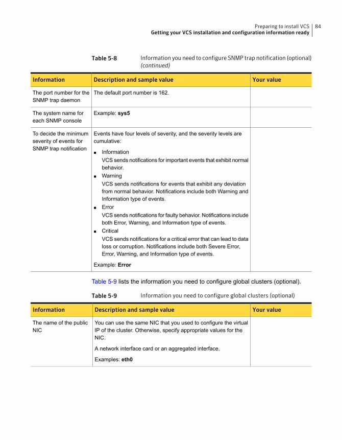
Table 5-8 Information you need to configure SNMP trap notification (optional)(continued)
Your valueDescription and sample valueInformation
The default port number is 162.The port number for theSNMP trap daemon
Example: sys5The system name foreach SNMP console
Events have four levels of severity, and the severity levels arecumulative:
■ InformationVCS sends notifications for important events that exhibit normalbehavior.
■ WarningVCS sends notifications for events that exhibit any deviationfrom normal behavior. Notifications include both Warning andInformation type of events.
■ ErrorVCS sends notifications for faulty behavior. Notifications includeboth Error, Warning, and Information type of events.
■ CriticalVCS sends notifications for a critical error that can lead to dataloss or corruption. Notifications include both Severe Error,Error, Warning, and Information type of events.
Example: Error
To decide the minimumseverity of events forSNMP trap notification
Table 5-9 lists the information you need to configure global clusters (optional).
Table 5-9 Information you need to configure global clusters (optional)
Your valueDescription and sample valueInformation
You can use the same NIC that you used to configure the virtualIP of the cluster. Otherwise, specify appropriate values for theNIC.
A network interface card or an aggregated interface.
Examples: eth0
The name of the publicNIC
84Preparing to install VCSGetting your VCS installation and configuration information ready
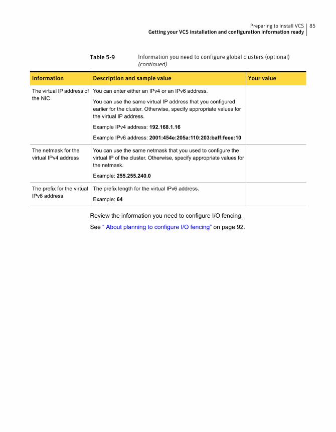
Table 5-9 Information you need to configure global clusters (optional)(continued)
Your valueDescription and sample valueInformation
You can enter either an IPv4 or an IPv6 address.
You can use the same virtual IP address that you configuredearlier for the cluster. Otherwise, specify appropriate values forthe virtual IP address.
Example IPv4 address: 192.168.1.16
Example IPv6 address: 2001:454e:205a:110:203:baff:feee:10
The virtual IP address ofthe NIC
You can use the same netmask that you used to configure thevirtual IP of the cluster. Otherwise, specify appropriate values forthe netmask.
Example: 255.255.240.0
The netmask for thevirtual IPv4 address
The prefix length for the virtual IPv6 address.
Example: 64
The prefix for the virtualIPv6 address
Review the information you need to configure I/O fencing.
See “ About planning to configure I/O fencing” on page 92.
85Preparing to install VCSGetting your VCS installation and configuration information ready
Installation using thescript-based installer
■ Chapter 6. Installing VCS
■ Chapter 7. Preparing to configure VCS clusters for data integrity
■ Chapter 8. Configuring VCS
■ Chapter 9. Configuring VCS clusters for data integrity
3Section
Installing VCS
This chapter includes the following topics:
■ Installing VCS using the installer
Installing VCS using the installerPerform the following steps to install VCS.
Note: The system from where you install VCS must run the same Linux distributionas the target systems.
To install VCS
1 Confirm that you are logged in as the superuser and you mounted the productdisc.
See “Mounting the product disc” on page 76.
2 If you want to install VCS using the product installer, perform the followingsteps:
■ Start the installer.
# ./installer
The installer starts with a copyright message and specifies the directorywhere the logs are created.
■ From the opening Selection Menu, choose I for "Install a Product."
■ From the displayed list of products to install, choose: Symantec ClusterServer.
If you want to install VCS using installvcs, perform the following steps:
6Chapter
■ Navigate to the folder that contains the installvcs.
# cd install_media/dist_arch/cluster_server
where dist is rhel6, rhel7, or sles11 and arch is x86_64.
■ Start the Install VCS program
# ./installvcs
The installer starts with a copyright message and specifies the directorywhere the logs are created.
If you want to install VCS in a VMware environment, with single sign-on betweenthe system and the Symantec High Availability Console enabled, perform thefollowing steps:
■ Create a file, say SSO_inputs_file, in the tmp directory with the followingcontents:$Obj::pool{Cfg}{sso_console_ip} = '1.2.3.4';$Obj::pool{Cfg}{sso_local_username} = 'root';$Obj::pool{Cfg}{sso_local_password} = 'encryptedpassword';
Note: You must enter only encrypted passwords in the SSO input files. Formore information:
■ Navigate to the directory that contains the installvcs.
# cd install_media/dist_arch/cluster_server
where dist is rhel6, rhel7, or sles11 and arch is x86_64.
■ Start the installvcs program:
# ./installvcs -require SSO_inputs_file
3 Enter y to agree to the End User License Agreement (EULA).
Do you agree with the terms of the End User License Agreement
as specified in the cluster_server/EULA/<lang>/EULA_SFHA_Ux_6.2.pdf
file present on media? [y,n,q,?] y
4 Choose the VCS RPMs that you want to install.
88Installing VCSInstalling VCS using the installer
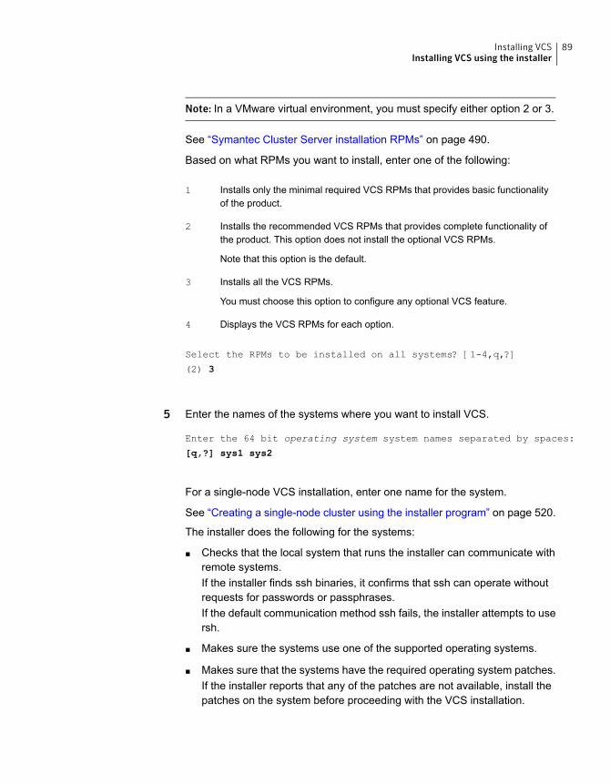
Note: In a VMware virtual environment, you must specify either option 2 or 3.
See “Symantec Cluster Server installation RPMs” on page 490.
Based on what RPMs you want to install, enter one of the following:
Installs only the minimal required VCS RPMs that provides basic functionalityof the product.
1
Installs the recommended VCS RPMs that provides complete functionality ofthe product. This option does not install the optional VCS RPMs.
Note that this option is the default.
2
Installs all the VCS RPMs.
You must choose this option to configure any optional VCS feature.
3
Displays the VCS RPMs for each option.4
Select the RPMs to be installed on all systems? [1-4,q,?]
(2) 3
5 Enter the names of the systems where you want to install VCS.
Enter the 64 bit operating system system names separated by spaces:
[q,?] sys1 sys2
For a single-node VCS installation, enter one name for the system.
See “Creating a single-node cluster using the installer program” on page 520.
The installer does the following for the systems:
■ Checks that the local system that runs the installer can communicate withremote systems.If the installer finds ssh binaries, it confirms that ssh can operate withoutrequests for passwords or passphrases.If the default communication method ssh fails, the installer attempts to usersh.
■ Makes sure the systems use one of the supported operating systems.
■ Makes sure that the systems have the required operating system patches.If the installer reports that any of the patches are not available, install thepatches on the system before proceeding with the VCS installation.
89Installing VCSInstalling VCS using the installer
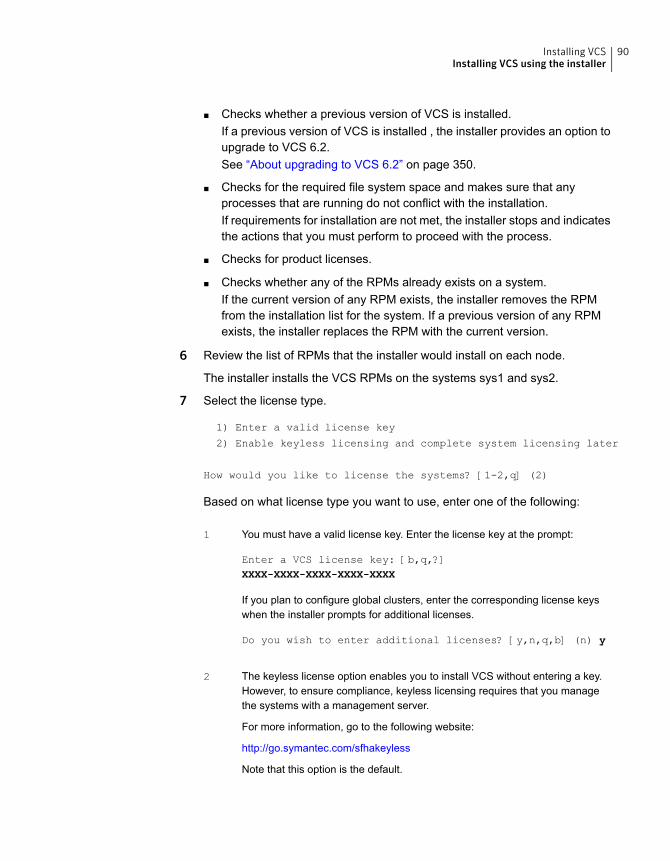
■ Checks whether a previous version of VCS is installed.If a previous version of VCS is installed , the installer provides an option toupgrade to VCS 6.2.See “About upgrading to VCS 6.2” on page 350.
■ Checks for the required file system space and makes sure that anyprocesses that are running do not conflict with the installation.If requirements for installation are not met, the installer stops and indicatesthe actions that you must perform to proceed with the process.
■ Checks for product licenses.
■ Checks whether any of the RPMs already exists on a system.If the current version of any RPM exists, the installer removes the RPMfrom the installation list for the system. If a previous version of any RPMexists, the installer replaces the RPM with the current version.
6 Review the list of RPMs that the installer would install on each node.
The installer installs the VCS RPMs on the systems sys1 and sys2.
7 Select the license type.
1) Enter a valid license key
2) Enable keyless licensing and complete system licensing later
How would you like to license the systems? [1-2,q] (2)
Based on what license type you want to use, enter one of the following:
You must have a valid license key. Enter the license key at the prompt:
Enter a VCS license key: [b,q,?]XXXX-XXXX-XXXX-XXXX-XXXX
If you plan to configure global clusters, enter the corresponding license keyswhen the installer prompts for additional licenses.
Do you wish to enter additional licenses? [y,n,q,b] (n) y
1
The keyless license option enables you to install VCS without entering a key.However, to ensure compliance, keyless licensing requires that you managethe systems with a management server.
For more information, go to the following website:
http://go.symantec.com/sfhakeyless
Note that this option is the default.
2
90Installing VCSInstalling VCS using the installer
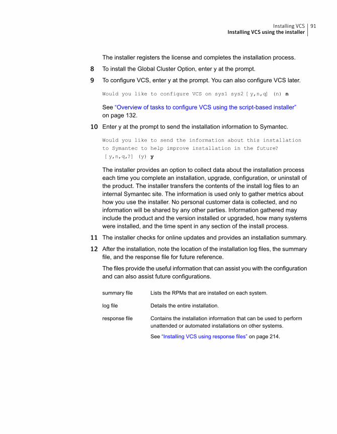
The installer registers the license and completes the installation process.
8 To install the Global Cluster Option, enter y at the prompt.
9 To configure VCS, enter y at the prompt. You can also configure VCS later.
Would you like to configure VCS on sys1 sys2 [y,n,q] (n) n
See “Overview of tasks to configure VCS using the script-based installer”on page 132.
10 Enter y at the prompt to send the installation information to Symantec.
Would you like to send the information about this installation
to Symantec to help improve installation in the future?
[y,n,q,?] (y) y
The installer provides an option to collect data about the installation processeach time you complete an installation, upgrade, configuration, or uninstall ofthe product. The installer transfers the contents of the install log files to aninternal Symantec site. The information is used only to gather metrics abouthow you use the installer. No personal customer data is collected, and noinformation will be shared by any other parties. Information gathered mayinclude the product and the version installed or upgraded, how many systemswere installed, and the time spent in any section of the install process.
11 The installer checks for online updates and provides an installation summary.
12 After the installation, note the location of the installation log files, the summaryfile, and the response file for future reference.
The files provide the useful information that can assist you with the configurationand can also assist future configurations.
Lists the RPMs that are installed on each system.summary file
Details the entire installation.log file
Contains the installation information that can be used to performunattended or automated installations on other systems.
See “Installing VCS using response files” on page 214.
response file
91Installing VCSInstalling VCS using the installer
Preparing to configure VCSclusters for data integrity
This chapter includes the following topics:
■ About planning to configure I/O fencing
■ Setting up the CP server
About planning to configure I/O fencingAfter you configure VCS with the installer, you must configure I/O fencing in thecluster for data integrity. Application clusters on release version 6.2 (HTTPS-basedcommunication) only support CP servers on release version 6.1 and later.
You can configure disk-based I/O fencing, server-based I/O fencing, ormajority-based I/O fencing. If your enterprise setup has multiple clusters that useVCS for clustering, Symantec recommends you to configure server-based I/Ofencing.
The coordination points in server-based fencing can include only CP servers or amix of CP servers and coordinator disks.
Symantec also supports server-based fencing with a single coordination point whichis a single highly available CP server that is hosted on an SFHA cluster.
7Chapter

Warning: For server-based fencing configurations that use a single coordinationpoint (CP server), the coordination point becomes a single point of failure. In suchconfigurations, the arbitration facility is not available during a failover of the CPserver in the SFHA cluster. So, if a network partition occurs on any applicationcluster during the CP server failover, the application cluster is brought down.Symantec recommends the use of single CP server-based fencing only in testenvironments.
You use majority fencing mechanism if you do not want to use coordination pointsto protect your cluster. Symantec recommends that you configure I/O fencing inmajority mode if you have a smaller cluster environment and you do not want toinvest additional disks or servers for the purposes of configuring fencing.
Note: Majority-based I/O fencing is not as robust as server-based or disk-basedI/O fencing in terms of high availability. With majority-based fencing mode, in rarecases, the cluster might become unavailable.
If you have installed VCS in a virtual environment that is not SCSI-3 PR compliant,you can configure non-SCSI-3 fencing.
See Figure 7-2 on page 95.
Figure 7-1 illustrates a high-level flowchart to configure I/O fencing for the VCScluster.
93Preparing to configure VCS clusters for data integrityAbout planning to configure I/O fencing

Figure 7-1 Workflow to configure I/O fencing
Initialize disks as VxVM disks
Check disks for I/O fencingcompliance
Manually configure disk-based I/Ofencing
Preparatory tasksvxdiskadm or vxdisksetup utilities
vxfenadm and vxfentsthdw utilities
Configuredisk-basedfencing (scsi3mode)
Configureserver-based fencing(customized mode)
Configuration tasksUse one of the following methods
Edit the values in the response fileyou created and use them withinstallsfcfsha -responsefile command
Install and configure VCS or SFHA on CP serversystems
Establish TCP/IP connection between CP server andVCS cluster
Edit the values in the response file you created anduse them with installvcs -responsefile command
Manually configure server-based I/O fencing
Preparatory tasksIdentify an existing CP server
Configuration tasksUse one of the following methods
Run the installsfcfsha -fencing, choose option 1, andfollow the prompts
If the CP server is clustered, set up shared storagefor the CP server
Run -configcps and follow the prompts (or) Manuallyconfigure CP server
Coordinationpoints for I/O
fencing?
Threedisks
At least one CPserver
Initialize disks as VxVM disks andCheck disks for I/O fencing compliance
For the disks that will serve as coordination points
Install and configure SFCFS
Run the installsfcfsha -fencing,choose option 2, and follow theprompts
(OR)Set up a CP server
Establish TCP/IP connection between CP server andVCS cluster
or
or
or
or
Choose to configure disk-basedfencing using the Web-based installer
or
Choose to configure server-based fencing using theWeb-based installer
orRun the installsfcfsha -fencing,choose option 3, and follow theprompts
Configuration tasksNo coordination points
Figure 7-2 illustrates a high-level flowchart to configure non-SCSI-3 I/O fencing forthe VCS cluster in virtual environments that do not support SCSI-3 PR.
94Preparing to configure VCS clusters for data integrityAbout planning to configure I/O fencing
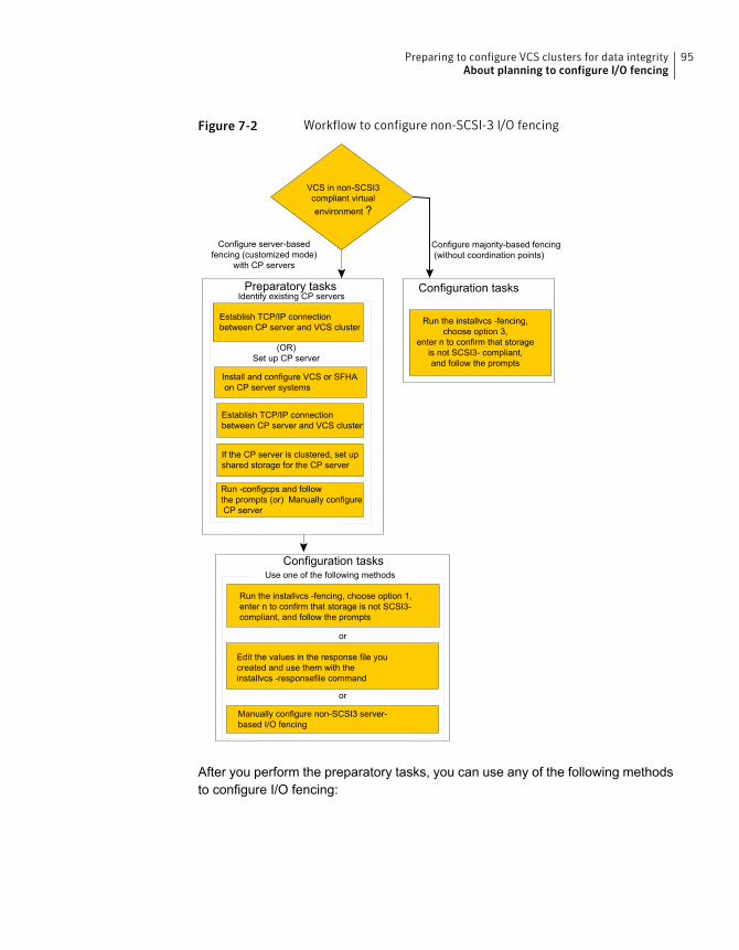
Figure 7-2 Workflow to configure non-SCSI-3 I/O fencing
Install and configure VCS or SFHAon CP server systems
Establish TCP/IP connectionbetween CP server and VCS cluster
Preparatory tasksIdentify existing CP servers
Configuration tasksUse one of the following methods
If the CP server is clustered, set upshared storage for the CP server
Run -configcps and followthe prompts (or) Manually configureCP server
VCS in non-SCSI3compliant virtualenvironment ?
(OR)Set up CP server
Establish TCP/IP connectionbetween CP server and VCS cluster
or
or
Configuration tasks
Configure majority-based fencing(without coordination points)
Run the installvcs -fencing, choose option 1,enter n to confirm that storage is not SCSI3-compliant, and follow the prompts
Run the installvcs -fencing,choose option 3,
enter n to confirm that storageis not SCSI3- compliant,and follow the prompts
Edit the values in the response file youcreated and use them with theinstallvcs -responsefile command
Manually configure non-SCSI3 server-based I/O fencing
Configure server-basedfencing (customized mode)
with CP servers
After you perform the preparatory tasks, you can use any of the following methodsto configure I/O fencing:
95Preparing to configure VCS clusters for data integrityAbout planning to configure I/O fencing

See “Setting up disk-based I/O fencing using installvcs” on page 158.
See “Setting up server-based I/O fencing using installvcs” on page 167.
See “Setting up non-SCSI-3 I/O fencing in virtual environments using installvcs”on page 180.
See “Setting up majority-based I/O fencing using installvcs” on page 182.
Using the installvcs
See “Configuring VCS for data integrity using the web-based installer” on page 199.Using the web-based installer
See “Response file variables to configure disk-based I/O fencing” on page 235.
See “Response file variables to configure server-based I/O fencing” on page 238.
See “Response file variables to configure non-SCSI-3 I/O fencing” on page 241.
See “Response file variables to configure majority-based I/O fencing” on page 243.
See “Configuring I/O fencing using response files” on page 234.
Using response files
See “Setting up disk-based I/O fencing manually” on page 286.
See “Setting up server-based I/O fencing manually” on page 291.
See “Setting up non-SCSI-3 fencing in virtual environments manually” on page 306.
See “Setting up majority-based I/O fencing manually ” on page 312.
Manually editing configuration files
You can also migrate from one I/O fencing configuration to another.
See the Symantec Storage foundation High Availability Administrator's Guide formore details.
Typical VCS cluster configuration with disk-based I/O fencingFigure 7-3 displays a typical VCS configuration with two nodes and shared storage.The configuration uses three coordinator disks for I/O fencing.
96Preparing to configure VCS clusters for data integrityAbout planning to configure I/O fencing
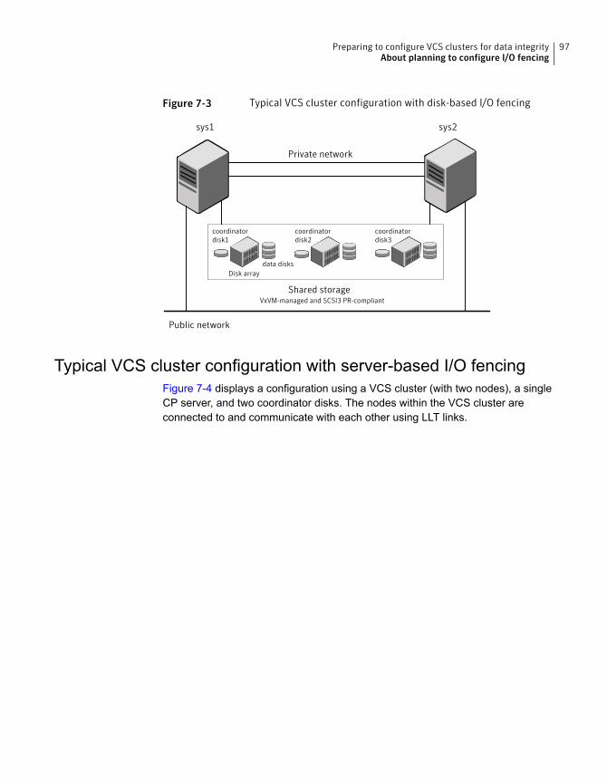
Figure 7-3 Typical VCS cluster configuration with disk-based I/O fencing
Public network
Private network
Shared storage
sys1 sys2
coordinatordisk1
data disksDisk array
coordinatordisk2
coordinatordisk3
VxVM-managed and SCSI3 PR-compliant
Typical VCS cluster configuration with server-based I/O fencingFigure 7-4 displays a configuration using a VCS cluster (with two nodes), a singleCP server, and two coordinator disks. The nodes within the VCS cluster areconnected to and communicate with each other using LLT links.
97Preparing to configure VCS clusters for data integrityAbout planning to configure I/O fencing
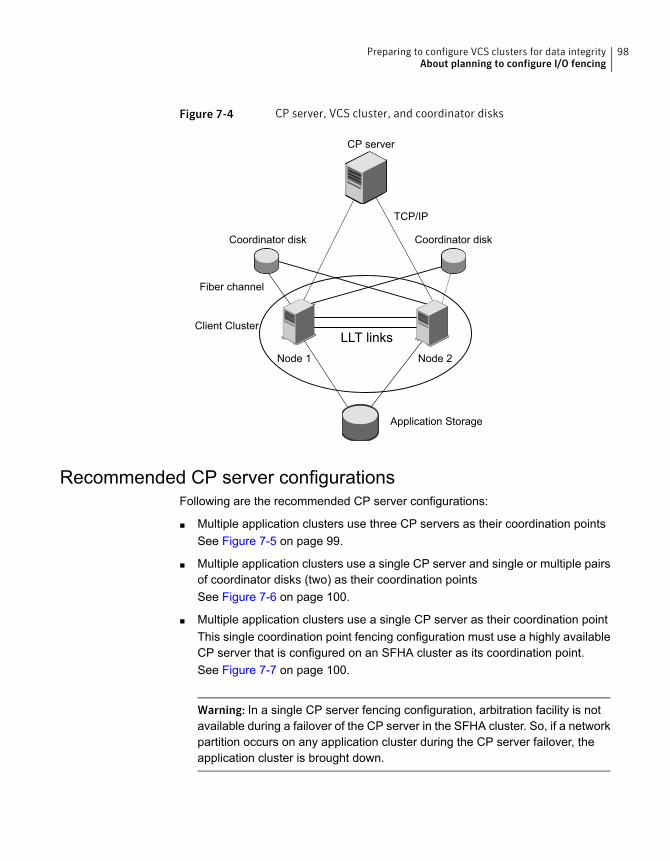
Figure 7-4 CP server, VCS cluster, and coordinator disks
Coordinator disk Coordinator disk
CP server
Client Cluster
Node 1 Node 2
Application Storage
LLT links
TCP/IP
Fiber channel
Recommended CP server configurationsFollowing are the recommended CP server configurations:
■ Multiple application clusters use three CP servers as their coordination pointsSee Figure 7-5 on page 99.
■ Multiple application clusters use a single CP server and single or multiple pairsof coordinator disks (two) as their coordination pointsSee Figure 7-6 on page 100.
■ Multiple application clusters use a single CP server as their coordination pointThis single coordination point fencing configuration must use a highly availableCP server that is configured on an SFHA cluster as its coordination point.See Figure 7-7 on page 100.
Warning: In a single CP server fencing configuration, arbitration facility is notavailable during a failover of the CP server in the SFHA cluster. So, if a networkpartition occurs on any application cluster during the CP server failover, theapplication cluster is brought down.
98Preparing to configure VCS clusters for data integrityAbout planning to configure I/O fencing
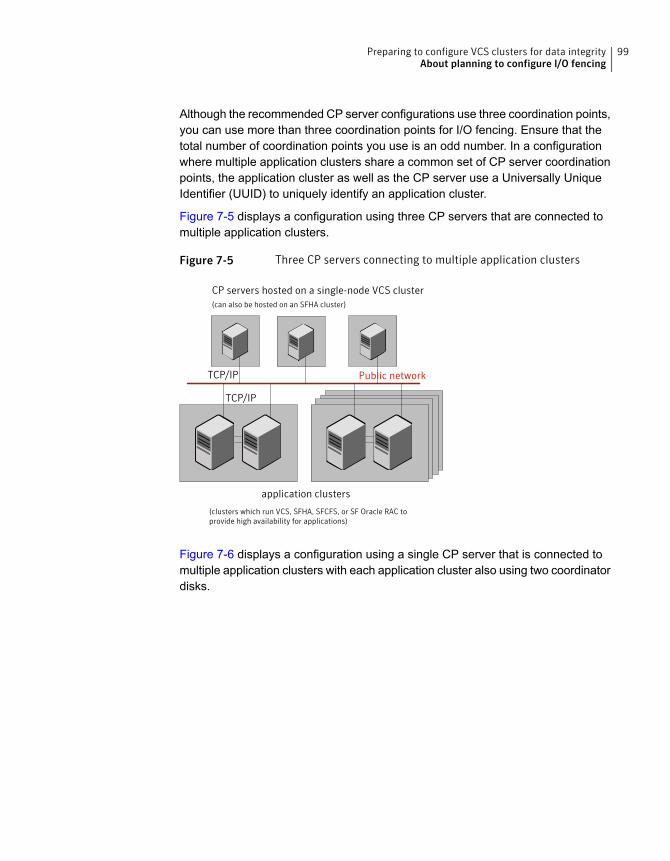
Although the recommended CP server configurations use three coordination points,you can use more than three coordination points for I/O fencing. Ensure that thetotal number of coordination points you use is an odd number. In a configurationwhere multiple application clusters share a common set of CP server coordinationpoints, the application cluster as well as the CP server use a Universally UniqueIdentifier (UUID) to uniquely identify an application cluster.
Figure 7-5 displays a configuration using three CP servers that are connected tomultiple application clusters.
Figure 7-5 Three CP servers connecting to multiple application clusters
Public networkTCP/IP
TCP/IP
CP servers hosted on a single-node VCS cluster(can also be hosted on an SFHA cluster)
application clusters
(clusters which run VCS, SFHA, SFCFS, or SF Oracle RAC toprovide high availability for applications)
Figure 7-6 displays a configuration using a single CP server that is connected tomultiple application clusters with each application cluster also using two coordinatordisks.
99Preparing to configure VCS clusters for data integrityAbout planning to configure I/O fencing
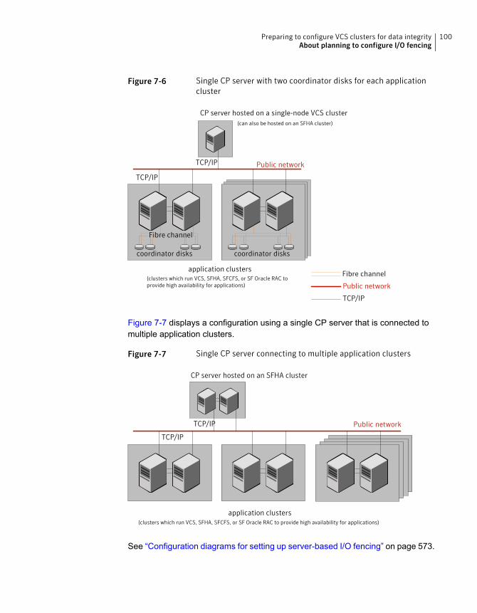
Figure 7-6 Single CP server with two coordinator disks for each applicationcluster
CP server hosted on a single-node VCS cluster
Public network
TCP/IP
TCP/IP
Fibre channel
Public network
TCP/IP
application clusters(clusters which run VCS, SFHA, SFCFS, or SF Oracle RAC toprovide high availability for applications)
Fibre channel
coordinator diskscoordinator disks
(can also be hosted on an SFHA cluster)
Figure 7-7 displays a configuration using a single CP server that is connected tomultiple application clusters.
Figure 7-7 Single CP server connecting to multiple application clusters
Public networkTCP/IP
TCP/IP
CP server hosted on an SFHA cluster
application clusters(clusters which run VCS, SFHA, SFCFS, or SF Oracle RAC to provide high availability for applications)
See “Configuration diagrams for setting up server-based I/O fencing” on page 573.
100Preparing to configure VCS clusters for data integrityAbout planning to configure I/O fencing
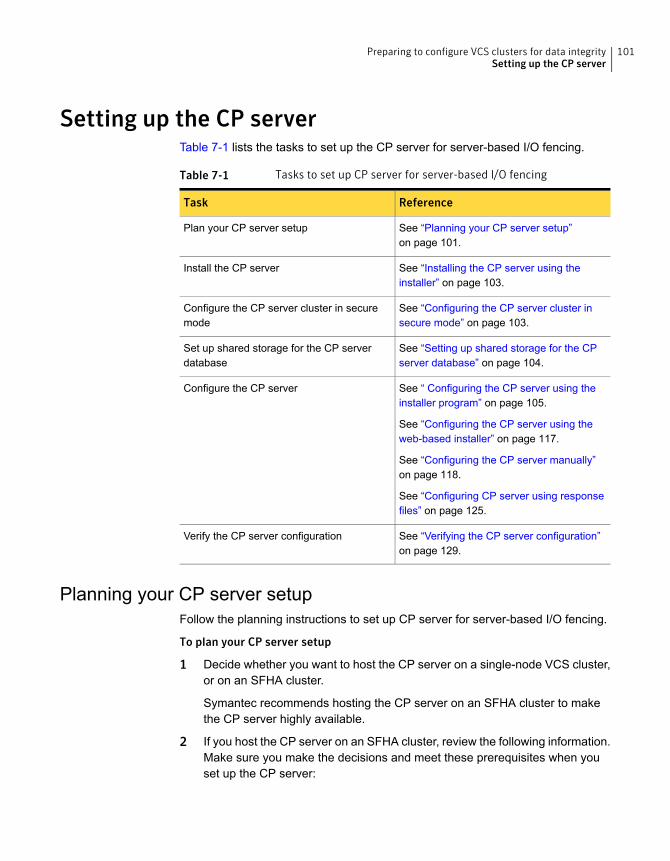
Setting up the CP serverTable 7-1 lists the tasks to set up the CP server for server-based I/O fencing.
Table 7-1 Tasks to set up CP server for server-based I/O fencing
ReferenceTask
See “Planning your CP server setup”on page 101.
Plan your CP server setup
See “Installing the CP server using theinstaller” on page 103.
Install the CP server
See “Configuring the CP server cluster insecure mode” on page 103.
Configure the CP server cluster in securemode
See “Setting up shared storage for the CPserver database” on page 104.
Set up shared storage for the CP serverdatabase
See “ Configuring the CP server using theinstaller program” on page 105.
See “Configuring the CP server using theweb-based installer” on page 117.
See “Configuring the CP server manually”on page 118.
See “Configuring CP server using responsefiles” on page 125.
Configure the CP server
See “Verifying the CP server configuration”on page 129.
Verify the CP server configuration
Planning your CP server setupFollow the planning instructions to set up CP server for server-based I/O fencing.
To plan your CP server setup
1 Decide whether you want to host the CP server on a single-node VCS cluster,or on an SFHA cluster.
Symantec recommends hosting the CP server on an SFHA cluster to makethe CP server highly available.
2 If you host the CP server on an SFHA cluster, review the following information.Make sure you make the decisions and meet these prerequisites when youset up the CP server:
101Preparing to configure VCS clusters for data integritySetting up the CP server
■ You must set up shared storage for the CP server database during yourCP server setup.
■ Decide whether you want to configure server-based fencing for the VCScluster (application cluster) with a single CP server as coordination pointor with at least three coordination points.Symantec recommends using at least three coordination points.
3 Decide whether you want to configure the CP server cluster for IPM-basedcommunication or HTTPS communication or both.
For IPM-based communication, the CP server on release 6.1 and later supportsclients prior to 6.1 release. When you configure the CP server, you are requiredto provide VIPs for IPM-based clients.
For HTTPS-based communication, the CP server on release 6.1 and later onlysupports clients on release 6.1 and later.
4 Decide whether you want to configure the CP server cluster in secure modefor IPM-based communication.
Symantec recommends configuring the CP server cluster in secure mode forIPM-based secure communication between the CP server and its clients (VCSclusters). Note that you use IPM-based communication if you want the CPserver to support clients that are installed with a release version prior to 6.1release.
5 Set up the hardware and network for your CP server.
See “CP server requirements” on page 41.
6 Have the following information handy for CP server configuration:
■ Name for the CP serverThe CP server name should not contain any special characters. CP servername can include alphanumeric characters, underscore, and hyphen.
■ Port number for the CP serverAllocate a TCP/IP port for use by the CP server.Valid port range is between 49152 and 65535. The default port number forHTTPS-based communication is 443 and for IPM-based securecommunication is 14250.
■ Virtual IP address, network interface, netmask, and networkhosts for theCP serverYou can configure multiple virtual IP addresses for the CP server.
102Preparing to configure VCS clusters for data integritySetting up the CP server
Installing the CP server using the installerPerform the following procedure to install and configure VCS or SFHA on CP serversystems.
To install and configure VCS or SFHA on the CP server systems
◆ Depending on whether your CP server uses a single system or multiple systems,perform the following tasks:
Install and configure VCS to create a single-node VCS cluster.
During installation of VCS 6.2, VRTScps will come under recommended set of RPMs.
Proceed to configure the CP server.
See “ Configuring the CP server using the installer program” on page 105.
See “Configuring the CP server manually” on page 118.
CP server setup uses asingle system
Install and configure SFHA to create an SFHA cluster. This makes the CP server highlyavailable.
Meet the following requirements for CP server:
■ During installation of SFHA 6.2, VRTScps will come under recommended set of RPMs.
See the Symantec Storage Foundation and High Availability Installation Guide for instructionson installing and configuring SFHA.
Proceed to set up shared storage for the CP server database.
CP server setup usesmultiple systems
Configuring the CP server cluster in secure modeYou must configure security on the CP server only if you want IPM-based (SymantecProduct Authentication Service) secure communication between the CP server andthe SFHA cluster (CP server clients). However, IPM-based communication enablesthe CP server to support application clusters prior to release 6.1.
This step secures the HAD communication on the CP server cluster.
Note: If you already configured the CP server cluster in secure mode during theVCS configuration, then skip this section.
103Preparing to configure VCS clusters for data integritySetting up the CP server
To configure the CP server cluster in secure mode
◆ Run the installer as follows to configure the CP server cluster in secure mode.
If you have VCS installed on the CP server, run the following command:
# /opt/VRTS/install/installvcs<version> -security
Where <version> is the specific release version.
If you have SFHA installed on the CP server, run the following command:
# /opt/VRTS/install/installsfha<version> -security
Where <version> is the specific release version.
See “About the script-based installer” on page 49.
Setting up shared storage for the CP server databaseIf you configured SFHA on the CP server cluster, perform the following procedureto set up shared storage for the CP server database.
The installer can set up shared storage for the CP server database when youconfigure CP server for the SFHA cluster.
Symantec recommends that you create a mirrored volume for the CP serverdatabase and that you use the VxFS file system type.
104Preparing to configure VCS clusters for data integritySetting up the CP server
To set up shared storage for the CP server database
1 Create a disk group containing the disks. You require two disks to create amirrored volume.
For example:
# vxdg init cps_dg disk1 disk2
2 Create a mirrored volume over the disk group.
For example:
# vxassist -g cps_dg make cps_vol volume_size layout=mirror
3 Create a file system over the volume.
The CP server configuration utility only supports vxfs file system type. If youuse an alternate file system, then you must configure CP server manually.
Depending on the operating system that your CP server runs, enter the followingcommand:
# mkfs -V vxfs /dev/vx/rdsk/cps_dg/cps_volumeAIX
# mkfs -t vxfs /dev/vx/rdsk/cps_dg/cps_volumeLinux
# mkfs -F vxfs /dev/vx/rdsk/cps_dg/cps_volumeSolaris
Configuring the CP server using the installer programUse the configcps option available in the installer program to configure the CPserver.
Perform one of the following procedures:
See “To configure the CP server on a single-node VCS cluster”on page 106.
For CP servers onsingle-node VCScluster:
See “To configure the CP server on an SFHA cluster” on page 111.For CP servers on anSFHA cluster:
105Preparing to configure VCS clusters for data integritySetting up the CP server
To configure the CP server on a single-node VCS cluster
1 Verify that the VRTScps RPM is installed on the node.
2 Run the installvcs<version> program with the configcps option.
# /opt/VRTS/install/installvcs<version> -configcps
Where <version> is the specific release version.
See “About the script-based installer” on page 49.
3 Installer checks the cluster information and prompts if you want to configureCP Server on the cluster.
Enter y to confirm.
4 Select an option based on how you want to configure Coordination Point server.
1) Configure Coordination Point Server on single node VCS system
2) Configure Coordination Point Server on SFHA cluster
3) Unconfigure Coordination Point Server
5 Enter the option: [1-3,q] 1.
The installer then runs the following preconfiguration checks:
■ Checks to see if a single-node VCS cluster is running with the supportedplatform.The CP server requires VCS to be installed and configured before itsconfiguration.
The installer automatically installs a license that is identified as a CPserver-specific license. It is installed even if a VCS license exists on the node.CP server-specific key ensures that you do not need to use a VCS license onthe single-node. It also ensures that Veritas Operations Manager (VOM)identifies the license on a single-node coordination point server as a CPserver-specific license and not as a VCS license.
6 Restart the VCS engine if the single-node only has a CP server-specific license.
A single node coordination point server will be configured and
VCS will be started in one node mode, do you want to
continue? [y,n,q] (y)
106Preparing to configure VCS clusters for data integritySetting up the CP server
7 Communication between the CP server and application clusters is secured byHTTPS from release 6.1.0 onwards. However, clusters on earlier releaseversions (prior to 6.1.0) that are using IPM-based communication are stillsupported.
Enter the name of the CP Server.
Enter the name of the CP Server: [b] cps1
8 Enter valid virtual IP addresses for the CP Server with HTTPS-based securecommunication. A CP Server can be configured with more than one virtual IPaddress. For HTTPS-based communication, only IPv4 addresses are supported.For IPM-based communication, both IPv4 and IPv6 addresses are supported.
Enter Virtual IP(s) for the CP server for HTTPS,
separated by a space: [b] 10.200.58.231 10.200.58.232
10.200.58.233
Note: Ensure that the virtual IP address of the CP server and the IP addressof the NIC interface on the CP server belongs to the same subnet of the IPnetwork. This is required for communication to happen between client nodesand CP server.
9 Enter the corresponding CP server port number for each virtual IP address orpress Enter to accept the default value (443).
Enter the default port '443' to be used for all the
virtual IP addresses for HTTPS communication or assign the
corresponding port number in the range [49152, 65535] for
each virtual IP address. Ensure that each port number is
separated by a single
space: [b] (443) 54442 54443 54447
10 Decide if you want to support clusters that are on releases prior to 6.1.0. Theseclusters use the Symantec Product Authentication Services (AT) (secureIPM-based protocol) to securely communicate with the CP servers.
Do you want to support older (prior to 6.1.0)
clusters? [y,n,q,b] (y)
107Preparing to configure VCS clusters for data integritySetting up the CP server
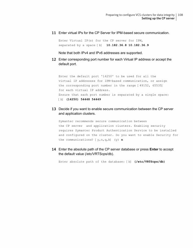
11 Enter virtual IPs for the CP Server for IPM-based secure communication.
Enter Virtual IP(s) for the CP server for IPM,
separated by a space [b] 10.182.36.8 10.182.36.9
Note that both IPv4 and IPv6 addresses are supported.
12 Enter corresponding port number for each Virtual IP address or accept thedefault port.
Enter the default port '14250' to be used for all the
virtual IP addresses for IPM-based communication, or assign
the corresponding port number in the range [49152, 65535]
for each virtual IP address.
Ensure that each port number is separated by a single space:
[b] (14250) 54448 54449
13 Decide if you want to enable secure communication between the CP serverand application clusters.
Symantec recommends secure communication between
the CP server and application clusters. Enabling security
requires Symantec Product Authentication Service to be installed
and configured on the cluster. Do you want to enable Security for
the communications? [y,n,q,b] (y) n
14 Enter the absolute path of the CP server database or press Enter to acceptthe default value (/etc/VRTScps/db).
Enter absolute path of the database: [b] (/etc/VRTScps/db)
108Preparing to configure VCS clusters for data integritySetting up the CP server
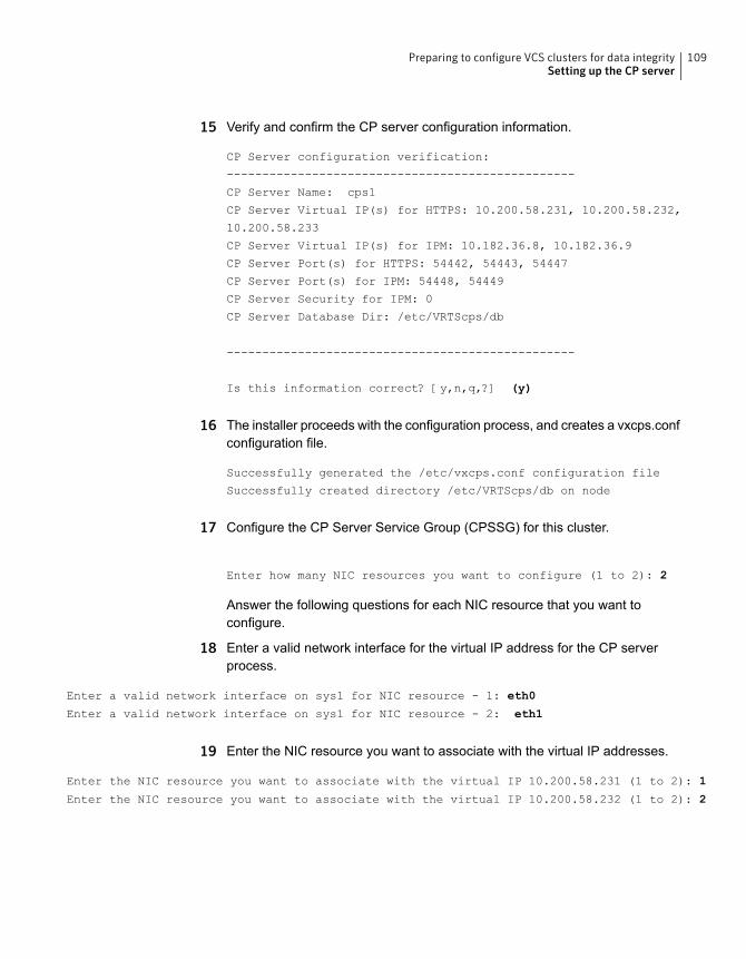
15 Verify and confirm the CP server configuration information.
CP Server configuration verification:
-------------------------------------------------
CP Server Name: cps1
CP Server Virtual IP(s) for HTTPS: 10.200.58.231, 10.200.58.232,
10.200.58.233
CP Server Virtual IP(s) for IPM: 10.182.36.8, 10.182.36.9
CP Server Port(s) for HTTPS: 54442, 54443, 54447
CP Server Port(s) for IPM: 54448, 54449
CP Server Security for IPM: 0
CP Server Database Dir: /etc/VRTScps/db
-------------------------------------------------
Is this information correct? [y,n,q,?] (y)
16 The installer proceeds with the configuration process, and creates a vxcps.confconfiguration file.
Successfully generated the /etc/vxcps.conf configuration file
Successfully created directory /etc/VRTScps/db on node
17 Configure the CP Server Service Group (CPSSG) for this cluster.
Enter how many NIC resources you want to configure (1 to 2): 2
Answer the following questions for each NIC resource that you want toconfigure.
18 Enter a valid network interface for the virtual IP address for the CP serverprocess.
Enter a valid network interface on sys1 for NIC resource - 1: eth0
Enter a valid network interface on sys1 for NIC resource - 2: eth1
19 Enter the NIC resource you want to associate with the virtual IP addresses.
Enter the NIC resource you want to associate with the virtual IP 10.200.58.231 (1 to 2): 1
Enter the NIC resource you want to associate with the virtual IP 10.200.58.232 (1 to 2): 2
109Preparing to configure VCS clusters for data integritySetting up the CP server
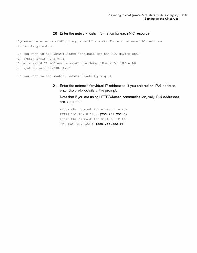
20 Enter the networkhosts information for each NIC resource.
Symantec recommends configuring NetworkHosts attribute to ensure NIC resource
to be always online
Do you want to add NetworkHosts attribute for the NIC device eth0
on system sys1? [y,n,q] y
Enter a valid IP address to configure NetworkHosts for NIC eth0
on system sys1: 10.200.56.22
Do you want to add another Network Host? [y,n,q] n
21 Enter the netmask for virtual IP addresses. If you entered an IPv6 address,enter the prefix details at the prompt.
Note that if you are using HTTPS-based communication, only IPv4 addressesare supported.
Enter the netmask for virtual IP for
HTTPS 192.169.0.220: (255.255.252.0)
Enter the netmask for virtual IP for
IPM 192.169.0.221: (255.255.252.0)
110Preparing to configure VCS clusters for data integritySetting up the CP server
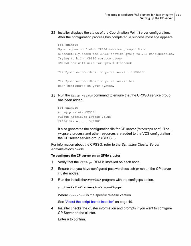
22 Installer displays the status of the Coordination Point Server configuration.After the configuration process has completed, a success message appears.
For example:
Updating main.cf with CPSSG service group.. Done
Successfully added the CPSSG service group to VCS configuration.
Trying to bring CPSSG service group
ONLINE and will wait for upto 120 seconds
The Symantec coordination point server is ONLINE
The Symantec coordination point server has
been configured on your system.
23 Run the hagrp -state command to ensure that the CPSSG service grouphas been added.
For example:
# hagrp -state CPSSG
#Group Attribute System Value
CPSSG State.... |ONLINE|
It also generates the configuration file for CP server (/etc/vxcps.conf). Thevxcpserv process and other resources are added to the VCS configuration inthe CP server service group (CPSSG).
For information about the CPSSG, refer to the Symantec Cluster ServerAdministrator's Guide.
To configure the CP server on an SFHA cluster
1 Verify that the VRTScps RPM is installed on each node.
2 Ensure that you have configured passwordless ssh or rsh on the CP servercluster nodes.
3 Run the installsfha<version> program with the configcps option.
# ./installsfha<version> -configcps
Where <version> is the specific release version.
See “About the script-based installer” on page 49.
4 Installer checks the cluster information and prompts if you want to configureCP Server on the cluster.
Enter y to confirm.
111Preparing to configure VCS clusters for data integritySetting up the CP server

5 Select an option based on how you want to configure Coordination Point server.
1) Configure Coordination Point Server on single node VCS system
2) Configure Coordination Point Server on SFHA cluster
3) Unconfigure Coordination Point Server
6 Enter 2 at the prompt to configure CP server on an SFHA cluster.
The installer then runs the following preconfiguration checks:
■ Checks to see if an SFHA cluster is running with the supported platform.The CP server requires SFHA to be installed and configured before itsconfiguration.
7 Communication between the CP server and application clusters is secured byHTTPS from Release 6.1.0 onwards. However, clusters on earlier releaseversions (prior to 6.1.0) that are using IPM-based communication are stillsupported.
Enter the name of the CP server.
Enter the name of the CP Server: [b] cps1
8 Enter valid virtual IP addresses for the CP Server. A CP Server can beconfigured with more than one virtual IP address. For HTTPS-basedcommunication, only IPv4 addresses are supported. For IPM-basedcommunication, both IPv4 and IPv6 addresses are supported
Enter Virtual IP(s) for the CP server for HTTPS,
separated by a space: [b] 10.200.58.231 10.200.58.232 10.200.58.233
9 Enter the corresponding CP server port number for each virtual IP address orpress Enter to accept the default value (443).
Enter the default port '443' to be used for all the virtual IP addresses
for HTTPS communication or assign the corresponding port number in the range [49152,
65535] for each virtual IP address. Ensure that each port number is separated by
a single space: [b] (443) 65535 65534 65537
10 Decide if you want to support clusters that are on releases prior to 6.1.0. Theseclusters use the Symantec Product Authentication Services (AT) (secureIPM-based protocol) to securely communicate with the CP servers.
Do you want to support older (prior to 6.1.0) clusters? [y,n,q,b] (y)
112Preparing to configure VCS clusters for data integritySetting up the CP server
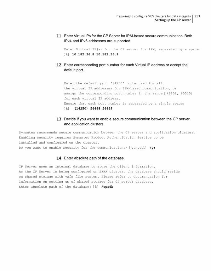
11 Enter Virtual IPs for the CP Server for IPM-based secure communication. BothIPv4 and IPv6 addresses are supported.
Enter Virtual IP(s) for the CP server for IPM, separated by a space:
[b] 10.182.36.8 10.182.36.9
12 Enter corresponding port number for each Virtual IP address or accept thedefault port.
Enter the default port '14250' to be used for all
the virtual IP addresses for IPM-based communication, or
assign the corresponding port number in the range [49152, 65535]
for each virtual IP address.
Ensure that each port number is separated by a single space:
[b] (14250) 54448 54449
13 Decide if you want to enable secure communication between the CP serverand application clusters.
Symantec recommends secure communication between the CP server and application clusters.
Enabling security requires Symantec Product Authentication Service to be
installed and configured on the cluster.
Do you want to enable Security for the communications? [y,n,q,b] (y)
14 Enter absolute path of the database.
CP Server uses an internal database to store the client information.
As the CP Server is being configured on SFHA cluster, the database should reside
on shared storage with vxfs file system. Please refer to documentation for
information on setting up of shared storage for CP server database.
Enter absolute path of the database: [b] /cpsdb
113Preparing to configure VCS clusters for data integritySetting up the CP server
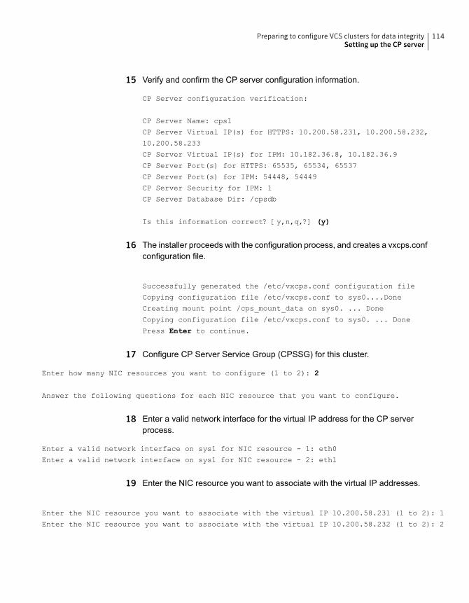
15 Verify and confirm the CP server configuration information.
CP Server configuration verification:
CP Server Name: cps1
CP Server Virtual IP(s) for HTTPS: 10.200.58.231, 10.200.58.232,
10.200.58.233
CP Server Virtual IP(s) for IPM: 10.182.36.8, 10.182.36.9
CP Server Port(s) for HTTPS: 65535, 65534, 65537
CP Server Port(s) for IPM: 54448, 54449
CP Server Security for IPM: 1
CP Server Database Dir: /cpsdb
Is this information correct? [y,n,q,?] (y)
16 The installer proceeds with the configuration process, and creates a vxcps.confconfiguration file.
Successfully generated the /etc/vxcps.conf configuration file
Copying configuration file /etc/vxcps.conf to sys0....Done
Creating mount point /cps_mount_data on sys0. ... Done
Copying configuration file /etc/vxcps.conf to sys0. ... Done
Press Enter to continue.
17 Configure CP Server Service Group (CPSSG) for this cluster.
Enter how many NIC resources you want to configure (1 to 2): 2
Answer the following questions for each NIC resource that you want to configure.
18 Enter a valid network interface for the virtual IP address for the CP serverprocess.
Enter a valid network interface on sys1 for NIC resource - 1: eth0
Enter a valid network interface on sys1 for NIC resource - 2: eth1
19 Enter the NIC resource you want to associate with the virtual IP addresses.
Enter the NIC resource you want to associate with the virtual IP 10.200.58.231 (1 to 2): 1
Enter the NIC resource you want to associate with the virtual IP 10.200.58.232 (1 to 2): 2
114Preparing to configure VCS clusters for data integritySetting up the CP server
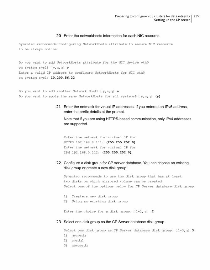
20 Enter the networkhosts information for each NIC resource.
Symantec recommends configuring NetworkHosts attribute to ensure NIC resource
to be always online
Do you want to add NetworkHosts attribute for the NIC device eth0
on system sys1? [y,n,q] y
Enter a valid IP address to configure NetworkHosts for NIC eth0
on system sys1: 10.200.56.22
Do you want to add another Network Host? [y,n,q] n
Do you want to apply the same NetworkHosts for all systems? [y,n,q] (y)
21 Enter the netmask for virtual IP addresses. If you entered an IPv6 address,enter the prefix details at the prompt.
Note that if you are using HTTPS-based communication, only IPv4 addressesare supported.
Enter the netmask for virtual IP for
HTTPS 192.168.0.111: (255.255.252.0)
Enter the netmask for virtual IP for
IPM 192.168.0.112: (255.255.252.0)
22 Configure a disk group for CP server database. You can choose an existingdisk group or create a new disk group.
Symantec recommends to use the disk group that has at least
two disks on which mirrored volume can be created.
Select one of the options below for CP Server database disk group:
1) Create a new disk group
2) Using an existing disk group
Enter the choice for a disk group: [1-2,q] 2
23 Select one disk group as the CP Server database disk group.
Select one disk group as CP Server database disk group: [1-3,q] 3
1) mycpsdg
2) cpsdg1
3) newcpsdg
115Preparing to configure VCS clusters for data integritySetting up the CP server
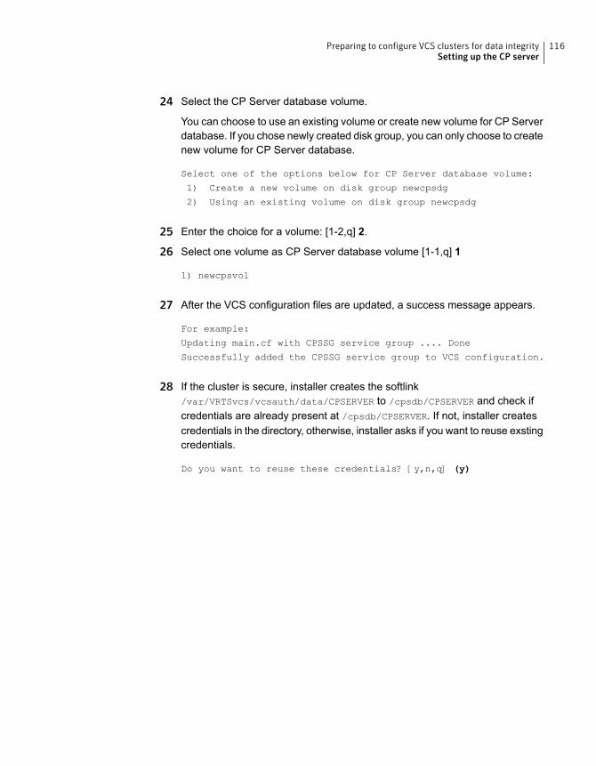
24 Select the CP Server database volume.
You can choose to use an existing volume or create new volume for CP Serverdatabase. If you chose newly created disk group, you can only choose to createnew volume for CP Server database.
Select one of the options below for CP Server database volume:
1) Create a new volume on disk group newcpsdg
2) Using an existing volume on disk group newcpsdg
25 Enter the choice for a volume: [1-2,q] 2.
26 Select one volume as CP Server database volume [1-1,q] 1
1) newcpsvol
27 After the VCS configuration files are updated, a success message appears.
For example:
Updating main.cf with CPSSG service group .... Done
Successfully added the CPSSG service group to VCS configuration.
28 If the cluster is secure, installer creates the softlink/var/VRTSvcs/vcsauth/data/CPSERVER to /cpsdb/CPSERVER and check ifcredentials are already present at /cpsdb/CPSERVER. If not, installer createscredentials in the directory, otherwise, installer asks if you want to reuse exstingcredentials.
Do you want to reuse these credentials? [y,n,q] (y)
116Preparing to configure VCS clusters for data integritySetting up the CP server

29 After the configuration process has completed, a success message appears.
For example:
Trying to bring CPSSG service group ONLINE and will wait for upto 120 seconds
The Symantec Coordination Point Server is ONLINE
The Symantec Coordination Point Server has been configured on your system.
30 Run the hagrp -state command to ensure that the CPSSG service grouphas been added.
For example:
# hagrp -state CPSSG
#Group Attribute System Value
CPSSG State cps1 |ONLINE|
CPSSG State cps2 |OFFLINE|
It also generates the configuration file for CP server (/etc/vxcps.conf). Thevxcpserv process and other resources are added to the VCS configuration inthe CP server service group (CPSSG).
For information about the CPSSG, refer to the Symantec Cluster ServerAdministrator's Guide.
Configuring the CP server using the web-based installerPerform the following steps to configure the CP server using the web-based installer.
To configure VCS on a cluster
1 Start the web-based installer.
See “Starting the web-based installer” on page 189.
2 On the Select a task and a product page, select the task and the product asfollows:
Configure CP serverTask
Symantec Cluster ServerProduct
Click Next.
3 On the Select Cluster page, enter the system names where you want toconfigure VCS and click Next.
117Preparing to configure VCS clusters for data integritySetting up the CP server
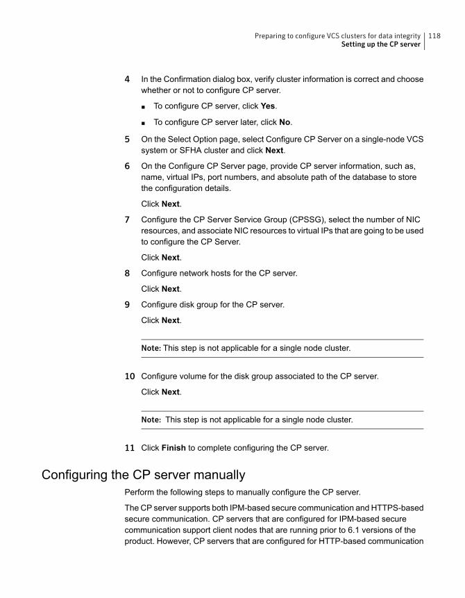
4 In the Confirmation dialog box, verify cluster information is correct and choosewhether or not to configure CP server.
■ To configure CP server, click Yes.
■ To configure CP server later, click No.
5 On the Select Option page, select Configure CP Server on a single-node VCSsystem or SFHA cluster and click Next.
6 On the Configure CP Server page, provide CP server information, such as,name, virtual IPs, port numbers, and absolute path of the database to storethe configuration details.
Click Next.
7 Configure the CP Server Service Group (CPSSG), select the number of NICresources, and associate NIC resources to virtual IPs that are going to be usedto configure the CP Server.
Click Next.
8 Configure network hosts for the CP server.
Click Next.
9 Configure disk group for the CP server.
Click Next.
Note: This step is not applicable for a single node cluster.
10 Configure volume for the disk group associated to the CP server.
Click Next.
Note: This step is not applicable for a single node cluster.
11 Click Finish to complete configuring the CP server.
Configuring the CP server manuallyPerform the following steps to manually configure the CP server.
The CP server supports both IPM-based secure communication and HTTPS-basedsecure communication. CP servers that are configured for IPM-based securecommunication support client nodes that are running prior to 6.1 versions of theproduct. However, CP servers that are configured for HTTP-based communication
118Preparing to configure VCS clusters for data integritySetting up the CP server
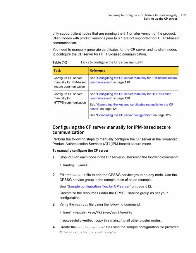
only support client nodes that are running the 6.1 or later version of the product.Client nodes with product versions prior to 6.1 are not supported for HTTPS-basedcommunication.
You need to manually generate certificates for the CP server and its client nodesto configure the CP server for HTTPS-based communication.
Table 7-2 Tasks to configure the CP server manually
ReferenceTask
See “Configuring the CP server manually for IPM-based securecommunication” on page 119.
Configure CP servermanually for IPM-basedsecure communication
See “Configuring the CP server manually for HTTPS-basedcommunication” on page 120.
See “Generating the key and certificates manually for the CPserver” on page 121.
See “Completing the CP server configuration” on page 125.
Configure CP servermanually forHTTPS-communication
Configuring the CP server manually for IPM-based securecommunicationPerform the following steps to manually configure the CP server in the SymantecProduct Authentication Services (AT) (IPM-based) secure mode.
To manually configure the CP server
1 Stop VCS on each node in the CP server cluster using the following command:
# hastop -local
2 Edit the main.cf file to add the CPSSG service group on any node. Use theCPSSG service group in the sample main.cf as an example:
See “Sample configuration files for CP server” on page 512.
Customize the resources under the CPSSG service group as per yourconfiguration.
3 Verify the main.cf file using the following command:
# hacf -verify /etc/VRTSvcs/conf/config
If successfully verified, copy this main.cf to all other cluster nodes.
4 Create the /etc/vxcps.conf file using the sample configuration file providedat /etc/vxcps/vxcps.conf.sample.
119Preparing to configure VCS clusters for data integritySetting up the CP server
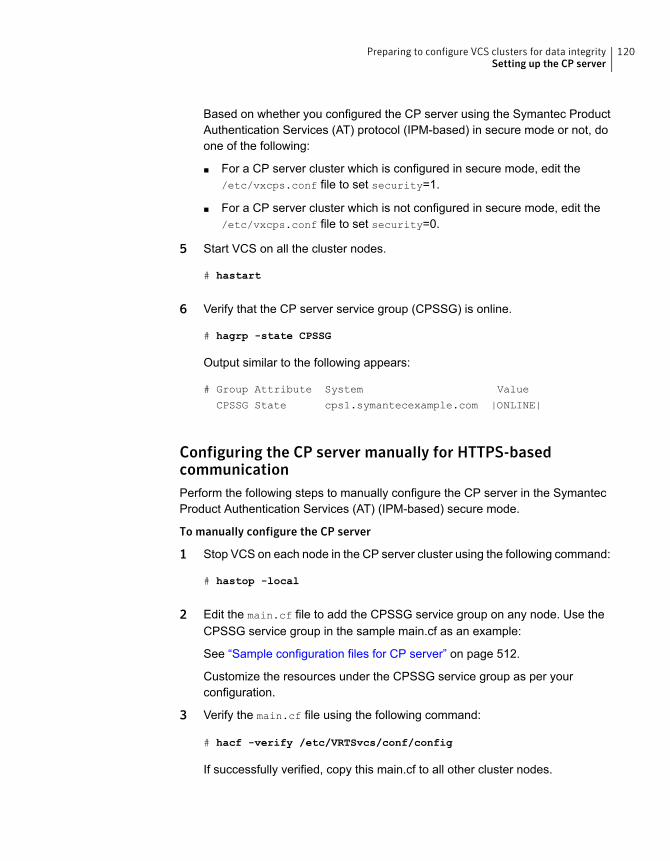
Based on whether you configured the CP server using the Symantec ProductAuthentication Services (AT) protocol (IPM-based) in secure mode or not, doone of the following:
■ For a CP server cluster which is configured in secure mode, edit the/etc/vxcps.conf file to set security=1.
■ For a CP server cluster which is not configured in secure mode, edit the/etc/vxcps.conf file to set security=0.
5 Start VCS on all the cluster nodes.
# hastart
6 Verify that the CP server service group (CPSSG) is online.
# hagrp -state CPSSG
Output similar to the following appears:
# Group Attribute System Value
CPSSG State cps1.symantecexample.com |ONLINE|
Configuring the CP server manually for HTTPS-basedcommunicationPerform the following steps to manually configure the CP server in the SymantecProduct Authentication Services (AT) (IPM-based) secure mode.
To manually configure the CP server
1 Stop VCS on each node in the CP server cluster using the following command:
# hastop -local
2 Edit the main.cf file to add the CPSSG service group on any node. Use theCPSSG service group in the sample main.cf as an example:
See “Sample configuration files for CP server” on page 512.
Customize the resources under the CPSSG service group as per yourconfiguration.
3 Verify the main.cf file using the following command:
# hacf -verify /etc/VRTSvcs/conf/config
If successfully verified, copy this main.cf to all other cluster nodes.
120Preparing to configure VCS clusters for data integritySetting up the CP server
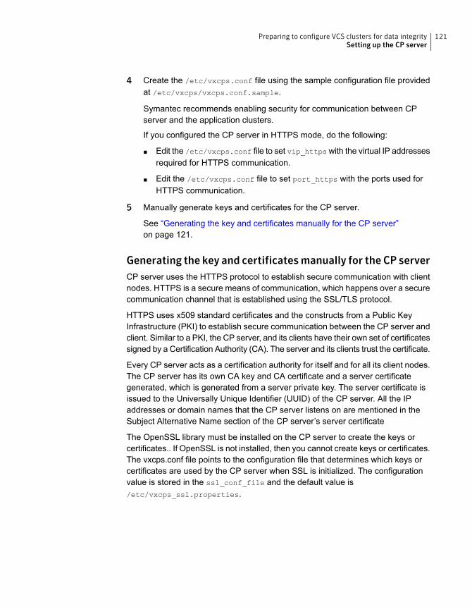
4 Create the /etc/vxcps.conf file using the sample configuration file providedat /etc/vxcps/vxcps.conf.sample.
Symantec recommends enabling security for communication between CPserver and the application clusters.
If you configured the CP server in HTTPS mode, do the following:
■ Edit the /etc/vxcps.conf file to set vip_https with the virtual IP addressesrequired for HTTPS communication.
■ Edit the /etc/vxcps.conf file to set port_https with the ports used forHTTPS communication.
5 Manually generate keys and certificates for the CP server.
See “Generating the key and certificates manually for the CP server”on page 121.
Generating the key and certificatesmanually for the CP serverCP server uses the HTTPS protocol to establish secure communication with clientnodes. HTTPS is a secure means of communication, which happens over a securecommunication channel that is established using the SSL/TLS protocol.
HTTPS uses x509 standard certificates and the constructs from a Public KeyInfrastructure (PKI) to establish secure communication between the CP server andclient. Similar to a PKI, the CP server, and its clients have their own set of certificatessigned by a Certification Authority (CA). The server and its clients trust the certificate.
Every CP server acts as a certification authority for itself and for all its client nodes.The CP server has its own CA key and CA certificate and a server certificategenerated, which is generated from a server private key. The server certificate isissued to the Universally Unique Identifier (UUID) of the CP server. All the IPaddresses or domain names that the CP server listens on are mentioned in theSubject Alternative Name section of the CP server’s server certificate
The OpenSSL library must be installed on the CP server to create the keys orcertificates.. If OpenSSL is not installed, then you cannot create keys or certificates.The vxcps.conf file points to the configuration file that determines which keys orcertificates are used by the CP server when SSL is initialized. The configurationvalue is stored in the ssl_conf_file and the default value is/etc/vxcps_ssl.properties.
121Preparing to configure VCS clusters for data integritySetting up the CP server
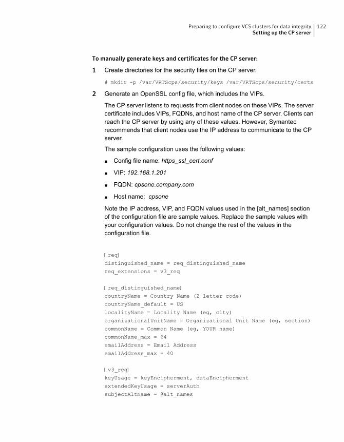
To manually generate keys and certificates for the CP server:
1 Create directories for the security files on the CP server.
# mkdir -p /var/VRTScps/security/keys /var/VRTScps/security/certs
2 Generate an OpenSSL config file, which includes the VIPs.
The CP server listens to requests from client nodes on these VIPs. The servercertificate includes VIPs, FQDNs, and host name of the CP server. Clients canreach the CP server by using any of these values. However, Symantecrecommends that client nodes use the IP address to communicate to the CPserver.
The sample configuration uses the following values:
■ Config file name: https_ssl_cert.conf
■ VIP: 192.168.1.201
■ FQDN: cpsone.company.com
■ Host name: cpsone
Note the IP address, VIP, and FQDN values used in the [alt_names] sectionof the configuration file are sample values. Replace the sample values withyour configuration values. Do not change the rest of the values in theconfiguration file.
[req]
distinguished_name = req_distinguished_name
req_extensions = v3_req
[req_distinguished_name]
countryName = Country Name (2 letter code)
countryName_default = US
localityName = Locality Name (eg, city)
organizationalUnitName = Organizational Unit Name (eg, section)
commonName = Common Name (eg, YOUR name)
commonName_max = 64
emailAddress = Email Address
emailAddress_max = 40
[v3_req]
keyUsage = keyEncipherment, dataEncipherment
extendedKeyUsage = serverAuth
subjectAltName = @alt_names
122Preparing to configure VCS clusters for data integritySetting up the CP server
[alt_names]
DNS.1 = cpsone.company.com
DNS.2 = cpsone
DNS.3 = 192.168.1.201
3 Generate a 4096-bit CA key that is used to create the CA certificate.
The key must be stored at /var/VRTScps/security/keys/ca.key. Ensurethat only root users can access the CA key, as the key can be misused tocreate fake certificates and compromise security.
# /usr/bin/openssl genrsa -out /var/VRTScps/security/keys/ca.key
4096
4 Generate a self-signed CA certificate.
# /usr/bin/openssl req -new -x509 -days days -key
/var/VRTScps/security/keys/ca.key -subj \
'/C=countryname/L=localityname/OU=COMPANY/CN=CACERT' -out \
/var/VRTScps/security/certs/ca.crt
Where, days is the days you want the certificate to remain valid, countrynameis the name of the country, localityname is the city, CACERT is the certificatename.
5 Generate a 2048-bit private key for CP server.
The key must be stored at /var/VRTScps/security/keys/server_privatekey.
# /usr/bin/openssl genrsa -out \
/var/VRTScps/security/keys/server_private.key 2048
6 Generate a Certificate Signing Request (CSR) for the server certificate.
The Certified Name (CN) in the certificate is the UUID of the CP server.
# /usr/bin/openssl genrsa -out
/var/VRTScps/security/keys/server_private.key 2048
123Preparing to configure VCS clusters for data integritySetting up the CP server
7 Generate a Certificate Signing Request (CSR) for the server certificate.
The Certified Name (CN) in the certificate is the UUID of the CP server.
# /usr/bin/openssl req -new -key
/var/VRTScps/security/keys/server_private.key \
-config https_ssl_cert.conf -subj \
'/C=CountryName/L=LocalityName/OU=COMPANY/CN=UUID' \
-out /var/VRTScps/security/certs/server.csr
Where, countryname is the name of the country, localityname is the city, UUIDis the certificate name.
8 Generate the server certificate by using the key certificate of the CA.
# /usr/bin/openssl x509 -req -days days -in
/var/VRTScps/security/certs/server.csr \
-CA /var/VRTScps/security/certs/ca.crt -CAkey \
/var/VRTScps/security/keys/ca.key \
-set_serial 01 -extensions v3_req -extfile https_ssl_cert.conf \
-out /var/VRTScps/security/certs/server.crt
Where, days is the days you want the certificate to remain valid,https_ssl_cert.conf is the configuration file name.
You successfully created the key and certificate required for the CP server.
9 Ensure that no other user except the root user can read the keys andcertificates.
10 Complete the CP server configuration.
See “Completing the CP server configuration” on page 125.
124Preparing to configure VCS clusters for data integritySetting up the CP server
Completing the CP server configurationTo verify the service groups and start VCS perform the following steps:
1 Start VCS on all the cluster nodes.
# hastart
2 Verify that the CP server service group (CPSSG) is online.
# hagrp -state CPSSG
Output similar to the following appears:
# Group Attribute System Value
CPSSG State cps1.symantecexample.com |ONLINE|
Configuring CP server using response filesYou can configure a CP server using a generated responsefile.
On a single node VCS cluster:
◆ Run the installvcs<version> command with the responsefile option toconfigure the CP server on a single node VCS cluster.
# /opt/VRTS/install/installvcs<version> -responsefile
'/tmp/sample1.res'
Where <version> is the specific release version.
See “About the script-based installer” on page 49.
On a SFHA cluster:
◆ Run the installsfha<version> command with the responsefile option toconfigure the CP server on a SFHA cluster.
# /opt/VRTS/install/installsfha<version> -responsefile
'/tmp/sample1.res'
Where <version> is the specific release version.
See “About the script-based installer” on page 49.
Response file variables to configure CP serverTable 7-3 describes the response file variables to configure CP server.
125Preparing to configure VCS clusters for data integritySetting up the CP server

Table 7-3 describes response file variables to configure CP server
DescriptionList orScalar
Variable
This variable performs CP serverconfiguration task
ScalarCFG{opt}{configcps}
This variable describes if the CP serverwill be configured on a singlenode VCScluster
ScalarCFG{cps_singlenode_config}
This variable describes if the CP serverwill be configured on a SFHA cluster
ScalarCFG{cps_sfha_config}
This variable describes if the CP serverwill be unconfigured
ScalarCFG{cps_unconfig}
This variable describes the name of theCP server
ScalarCFG{cpsname}
This variable describes the absolute pathof CP server database
ScalarCFG{cps_db_dir}
This variable describes if security isconfigured for the CP server
ScalarCFG{cps_security}
This variable describes if reusing theexisting credentials for the CP server
ScalarCFG{cps_reuse_cred}
This variable describes the virtual IPaddresses for the CP server configuredfor HTTPS-based communication
ListCFG{cps_https_vips}
This variable describes the virtual IPaddresses for the CP server configuredfor IPM-based communication
ListCFG{cps_ipm_vips}
This variable describes the port numberfor the virtual IP addresses for the CPserver configured for HTTPS-basedcommunication
ListCFG{cps_https_ports}
This variable describes the port numberfor the virtual IP addresses for the CPserver configured for IPM-basedcommunication
ListCFG{cps_ipm_ports}
This variable describes the NICs of thesystems for the virtual IP address
ListCFG{cps_nic_list}{cpsvip<n>}
126Preparing to configure VCS clusters for data integritySetting up the CP server
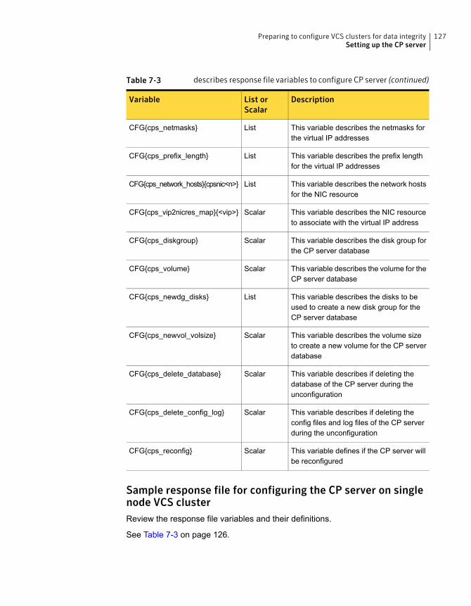
Table 7-3 describes response file variables to configure CP server (continued)
DescriptionList orScalar
Variable
This variable describes the netmasks forthe virtual IP addresses
ListCFG{cps_netmasks}
This variable describes the prefix lengthfor the virtual IP addresses
ListCFG{cps_prefix_length}
This variable describes the network hostsfor the NIC resource
ListCFG{cps_network_hosts}{cpsnic<n>}
This variable describes the NIC resourceto associate with the virtual IP address
ScalarCFG{cps_vip2nicres_map}{<vip>}
This variable describes the disk group forthe CP server database
ScalarCFG{cps_diskgroup}
This variable describes the volume for theCP server database
ScalarCFG{cps_volume}
This variable describes the disks to beused to create a new disk group for theCP server database
ListCFG{cps_newdg_disks}
This variable describes the volume sizeto create a new volume for the CP serverdatabase
ScalarCFG{cps_newvol_volsize}
This variable describes if deleting thedatabase of the CP server during theunconfiguration
ScalarCFG{cps_delete_database}
This variable describes if deleting theconfig files and log files of the CP serverduring the unconfiguration
ScalarCFG{cps_delete_config_log}
This variable defines if the CP server willbe reconfigured
ScalarCFG{cps_reconfig}
Sample response file for configuring the CP server on singlenode VCS clusterReview the response file variables and their definitions.
See Table 7-3 on page 126.
127Preparing to configure VCS clusters for data integritySetting up the CP server
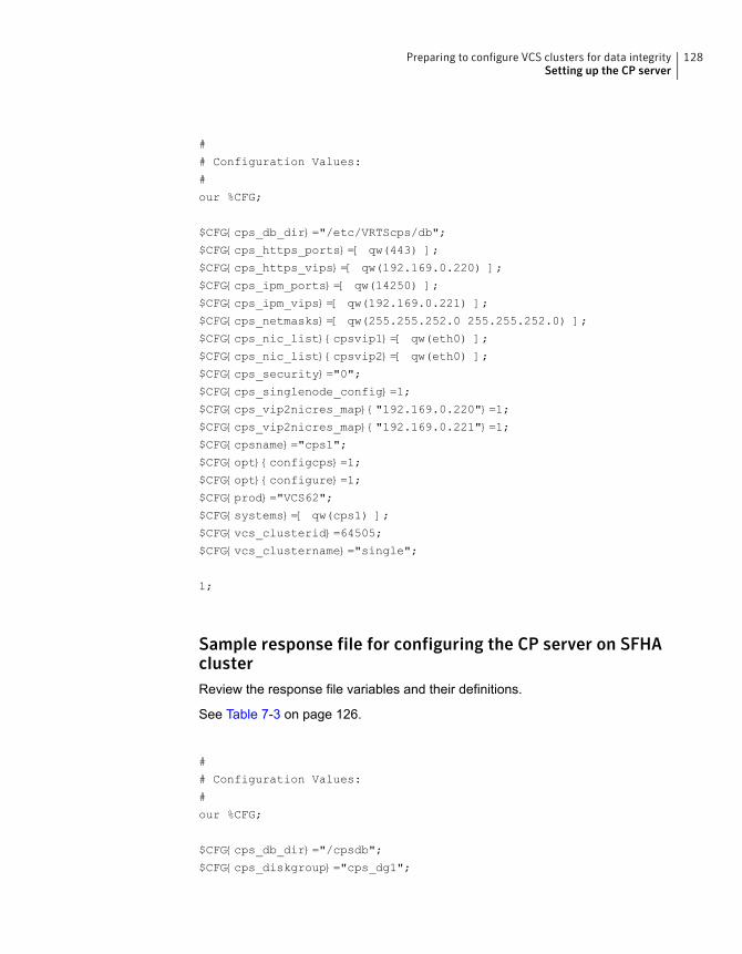
#
# Configuration Values:
#
our %CFG;
$CFG{cps_db_dir}="/etc/VRTScps/db";
$CFG{cps_https_ports}=[ qw(443) ];
$CFG{cps_https_vips}=[ qw(192.169.0.220) ];
$CFG{cps_ipm_ports}=[ qw(14250) ];
$CFG{cps_ipm_vips}=[ qw(192.169.0.221) ];
$CFG{cps_netmasks}=[ qw(255.255.252.0 255.255.252.0) ];
$CFG{cps_nic_list}{cpsvip1}=[ qw(eth0) ];
$CFG{cps_nic_list}{cpsvip2}=[ qw(eth0) ];
$CFG{cps_security}="0";
$CFG{cps_singlenode_config}=1;
$CFG{cps_vip2nicres_map}{"192.169.0.220"}=1;
$CFG{cps_vip2nicres_map}{"192.169.0.221"}=1;
$CFG{cpsname}="cps1";
$CFG{opt}{configcps}=1;
$CFG{opt}{configure}=1;
$CFG{prod}="VCS62";
$CFG{systems}=[ qw(cps1) ];
$CFG{vcs_clusterid}=64505;
$CFG{vcs_clustername}="single";
1;
Sample response file for configuring the CP server on SFHAclusterReview the response file variables and their definitions.
See Table 7-3 on page 126.
#
# Configuration Values:
#
our %CFG;
$CFG{cps_db_dir}="/cpsdb";
$CFG{cps_diskgroup}="cps_dg1";
128Preparing to configure VCS clusters for data integritySetting up the CP server
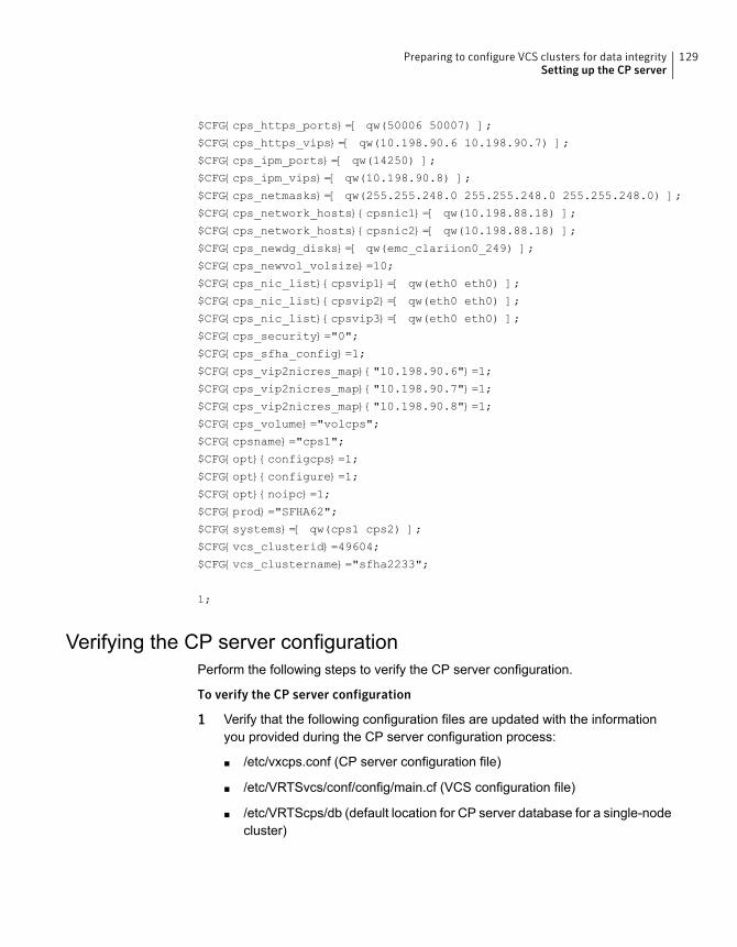
$CFG{cps_https_ports}=[ qw(50006 50007) ];
$CFG{cps_https_vips}=[ qw(10.198.90.6 10.198.90.7) ];
$CFG{cps_ipm_ports}=[ qw(14250) ];
$CFG{cps_ipm_vips}=[ qw(10.198.90.8) ];
$CFG{cps_netmasks}=[ qw(255.255.248.0 255.255.248.0 255.255.248.0) ];
$CFG{cps_network_hosts}{cpsnic1}=[ qw(10.198.88.18) ];
$CFG{cps_network_hosts}{cpsnic2}=[ qw(10.198.88.18) ];
$CFG{cps_newdg_disks}=[ qw(emc_clariion0_249) ];
$CFG{cps_newvol_volsize}=10;
$CFG{cps_nic_list}{cpsvip1}=[ qw(eth0 eth0) ];
$CFG{cps_nic_list}{cpsvip2}=[ qw(eth0 eth0) ];
$CFG{cps_nic_list}{cpsvip3}=[ qw(eth0 eth0) ];
$CFG{cps_security}="0";
$CFG{cps_sfha_config}=1;
$CFG{cps_vip2nicres_map}{"10.198.90.6"}=1;
$CFG{cps_vip2nicres_map}{"10.198.90.7"}=1;
$CFG{cps_vip2nicres_map}{"10.198.90.8"}=1;
$CFG{cps_volume}="volcps";
$CFG{cpsname}="cps1";
$CFG{opt}{configcps}=1;
$CFG{opt}{configure}=1;
$CFG{opt}{noipc}=1;
$CFG{prod}="SFHA62";
$CFG{systems}=[ qw(cps1 cps2) ];
$CFG{vcs_clusterid}=49604;
$CFG{vcs_clustername}="sfha2233";
1;
Verifying the CP server configurationPerform the following steps to verify the CP server configuration.
To verify the CP server configuration
1 Verify that the following configuration files are updated with the informationyou provided during the CP server configuration process:
■ /etc/vxcps.conf (CP server configuration file)
■ /etc/VRTSvcs/conf/config/main.cf (VCS configuration file)
■ /etc/VRTScps/db (default location for CP server database for a single-nodecluster)
129Preparing to configure VCS clusters for data integritySetting up the CP server
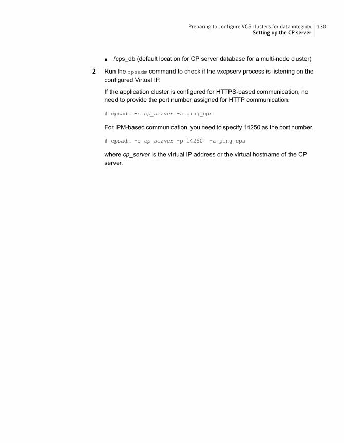
■ /cps_db (default location for CP server database for a multi-node cluster)
2 Run the cpsadm command to check if the vxcpserv process is listening on theconfigured Virtual IP.
If the application cluster is configured for HTTPS-based communication, noneed to provide the port number assigned for HTTP communication.
# cpsadm -s cp_server -a ping_cps
For IPM-based communication, you need to specify 14250 as the port number.
# cpsadm -s cp_server -p 14250 -a ping_cps
where cp_server is the virtual IP address or the virtual hostname of the CPserver.
130Preparing to configure VCS clusters for data integritySetting up the CP server
Configuring VCS
This chapter includes the following topics:
■ Overview of tasks to configure VCS using the script-based installer
■ Starting the software configuration
■ Specifying systems for configuration
■ Configuring the cluster name
■ Configuring private heartbeat links
■ Configuring the virtual IP of the cluster
■ Configuring Symantec Cluster Server in secure mode
■ Setting up trust relationships for your VCS cluster
■ Configuring a secure cluster node by node
■ Adding VCS users
■ Configuring SMTP email notification
■ Configuring SNMP trap notification
■ Configuring global clusters
■ Completing the VCS configuration
■ Verifying and updating licenses on the system
8Chapter
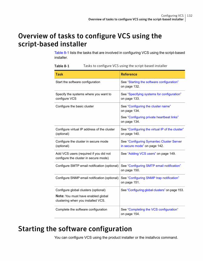
Overview of tasks to configure VCS using thescript-based installer
Table 8-1 lists the tasks that are involved in configuring VCS using the script-basedinstaller.
Table 8-1 Tasks to configure VCS using the script-based installer
ReferenceTask
See “Starting the software configuration”on page 132.
Start the software configuration
See “Specifying systems for configuration”on page 133.
Specify the systems where you want toconfigure VCS
See “Configuring the cluster name”on page 134.
See “Configuring private heartbeat links”on page 134.
Configure the basic cluster
See “Configuring the virtual IP of the cluster”on page 140.
Configure virtual IP address of the cluster(optional)
See “Configuring Symantec Cluster Serverin secure mode” on page 142.
Configure the cluster in secure mode(optional)
See “Adding VCS users” on page 149.Add VCS users (required if you did notconfigure the cluster in secure mode)
See “Configuring SMTP email notification”on page 150.
Configure SMTP email notification (optional)
See “Configuring SNMP trap notification”on page 151.
Configure SNMP email notification (optional)
See “Configuring global clusters” on page 153.Configure global clusters (optional)
Note: You must have enabled globalclustering when you installed VCS.
See “Completing the VCS configuration”on page 154.
Complete the software configuration
Starting the software configurationYou can configure VCS using the product installer or the installvcs command.
132Configuring VCSOverview of tasks to configure VCS using the script-based installer
Note: If you want to reconfigure VCS, before you start the installer you must stopall the resources that are under VCS control using the hastop command or thehagrp -offline command.
To configure VCS using the product installer
1 Confirm that you are logged in as the superuser and that you have mountedthe product disc.
2 Start the installer.
# ./installer
The installer starts the product installation program with a copyright messageand specifies the directory where the logs are created.
3 From the opening Selection Menu, choose: C for "Configure an InstalledProduct."
4 From the displayed list of products to configure, choose the correspondingnumber for your product:
Symantec Cluster Server
To configure VCS using the installvcs program
1 Confirm that you are logged in as the superuser.
2 Start the installvcs program.
# /opt/VRTS/install/installvcs<version> -configure
Where <version> is the specific release version.
See “About the script-based installer” on page 49.
The installer begins with a copyright message and specifies the directory wherethe logs are created.
Specifying systems for configurationThe installer prompts for the system names on which you want to configure VCS.The installer performs an initial check on the systems that you specify.
133Configuring VCSSpecifying systems for configuration
To specify system names for configuration
1 Enter the names of the systems where you want to configure VCS.
Enter the operating_system system names separated
by spaces: [q,?] (sys1) sys1 sys2
2 Review the output as the installer verifies the systems you specify.
The installer does the following tasks:
■ Checks that the local node running the installer can communicate withremote nodesIf the installer finds ssh binaries, it confirms that ssh can operate withoutrequests for passwords or passphrases. If ssh binaries cannot communicatewith remote nodes, the installer tries rsh binaries. And if both ssh and rshbinaries fail, the installer prompts to help the user to setup ssh or rshbinaries.
■ Makes sure that the systems are running with the supported operatingsystem
■ Checks whether VCS is installed
■ Exits if VCS 6.2 is not installed
3 Review the installer output about the I/O fencing configuration and confirmwhether you want to configure fencing in enabled mode.
Do you want to configure I/O Fencing in enabled mode? [y,n,q,?] (y)
See “ About planning to configure I/O fencing” on page 92.
Configuring the cluster nameEnter the cluster information when the installer prompts you.
To configure the cluster
1 Review the configuration instructions that the installer presents.
2 Enter a unique cluster name.
Enter the unique cluster name: [q,?] clus1
Configuring private heartbeat linksYou now configure the private heartbeat links that LLT uses.
134Configuring VCSConfiguring the cluster name
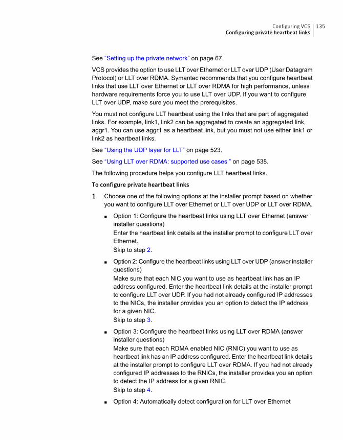
See “Setting up the private network” on page 67.
VCS provides the option to use LLT over Ethernet or LLT over UDP (User DatagramProtocol) or LLT over RDMA. Symantec recommends that you configure heartbeatlinks that use LLT over Ethernet or LLT over RDMA for high performance, unlesshardware requirements force you to use LLT over UDP. If you want to configureLLT over UDP, make sure you meet the prerequisites.
You must not configure LLT heartbeat using the links that are part of aggregatedlinks. For example, link1, link2 can be aggregated to create an aggregated link,aggr1. You can use aggr1 as a heartbeat link, but you must not use either link1 orlink2 as heartbeat links.
See “Using the UDP layer for LLT” on page 523.
See “Using LLT over RDMA: supported use cases ” on page 538.
The following procedure helps you configure LLT heartbeat links.
To configure private heartbeat links
1 Choose one of the following options at the installer prompt based on whetheryou want to configure LLT over Ethernet or LLT over UDP or LLT over RDMA.
■ Option 1: Configure the heartbeat links using LLT over Ethernet (answerinstaller questions)Enter the heartbeat link details at the installer prompt to configure LLT overEthernet.Skip to step 2.
■ Option 2: Configure the heartbeat links using LLT over UDP (answer installerquestions)Make sure that each NIC you want to use as heartbeat link has an IPaddress configured. Enter the heartbeat link details at the installer promptto configure LLT over UDP. If you had not already configured IP addressesto the NICs, the installer provides you an option to detect the IP addressfor a given NIC.Skip to step 3.
■ Option 3: Configure the heartbeat links using LLT over RDMA (answerinstaller questions)Make sure that each RDMA enabled NIC (RNIC) you want to use asheartbeat link has an IP address configured. Enter the heartbeat link detailsat the installer prompt to configure LLT over RDMA. If you had not alreadyconfigured IP addresses to the RNICs, the installer provides you an optionto detect the IP address for a given RNIC.Skip to step 4.
■ Option 4: Automatically detect configuration for LLT over Ethernet
135Configuring VCSConfiguring private heartbeat links

Allow the installer to automatically detect the heartbeat link details toconfigure LLT over Ethernet. The installer tries to detect all connected linksbetween all systems.Make sure that you activated the NICs for the installer to be able to detectand automatically configure the heartbeat links.Skip to step 7.
Note: Option 4 is not available when the configuration is a single nodeconfiguration.
2 If you chose option 1, enter the network interface card details for the privateheartbeat links.
The installer discovers and lists the network interface cards.
You must not enter the network interface card that is used for the public network(typically eth0.)
Enter the NIC for the first private heartbeat link on sys1:
[b,q,?] eth1
eth1 has an IP address configured on it. It could be a
public NIC on sys1.
Are you sure you want to use eth1 for the first private
heartbeat link? [y,n,q,b,?] (n) y
Would you like to configure a second private heartbeat link?
[y,n,q,b,?] (y)
Enter the NIC for the second private heartbeat link on sys1:
[b,q,?] eth2
eth2 has an IP address configured on it. It could be a
public NIC on sys1.
Are you sure you want to use eth2 for the second private
heartbeat link? [y,n,q,b,?] (n) y
Would you like to configure a third private heartbeat link?
[y,n,q,b,?](n)
Do you want to configure an additional low priority heartbeat
link? [y,n,q,b,?] (n)
136Configuring VCSConfiguring private heartbeat links

3 If you chose option 2, enter the NIC details for the private heartbeat links. Thisstep uses examples such as private_NIC1 or private_NIC2 to refer to theavailable names of the NICs.
Enter the NIC for the first private heartbeat
link on sys1: [b,q,?] private_NIC1
Do you want to use address 192.168.0.1 for the
first private heartbeat link on sys1: [y,n,q,b,?] (y)
Enter the UDP port for the first private heartbeat
link on sys1: [b,q,?] (50000)
Would you like to configure a second private
heartbeat link? [y,n,q,b,?] (y)
Enter the NIC for the second private heartbeat
link on sys1: [b,q,?] private_NIC2
Do you want to use address 192.168.1.1 for the
second private heartbeat link on sys1: [y,n,q,b,?] (y)
Enter the UDP port for the second private heartbeat
link on sys1: [b,q,?] (50001)
Do you want to configure an additional low priority
heartbeat link? [y,n,q,b,?] (n) y
Enter the NIC for the low priority heartbeat
link on sys1: [b,q,?] (private_NIC0)
Do you want to use address 192.168.3.1 for
the low priority heartbeat link on sys1: [y,n,q,b,?] (y)
Enter the UDP port for the low priority heartbeat
link on sys1: [b,q,?] (50004)
137Configuring VCSConfiguring private heartbeat links

4 If you chose option 3, choose the interconnect type to configure RDMA.
1) Converged Ethernet (RoCE)
2) InfiniBand
b) Back to previous menu
Choose the RDMA interconnect type [1-2,b,q,?] (1) 2
The system displays the details such as the required OS files, drivers requiredfor RDMA , and the IP addresses for the NICs.
A sample output of the IP addresses assigned to the RDMA enabled NICsusing InfiniBand network. Note that with RoCE, the RDMA NIC values arerepresented as eth0, eth1, and so on.
System RDMA NIC IP Address
=================================================================
sys1 ib0 192.168.0.1
sys1 ib1 192.168.3.1
sys2 ib0 192.168.0.2
sys2 ib1 192.168.3.2
138Configuring VCSConfiguring private heartbeat links
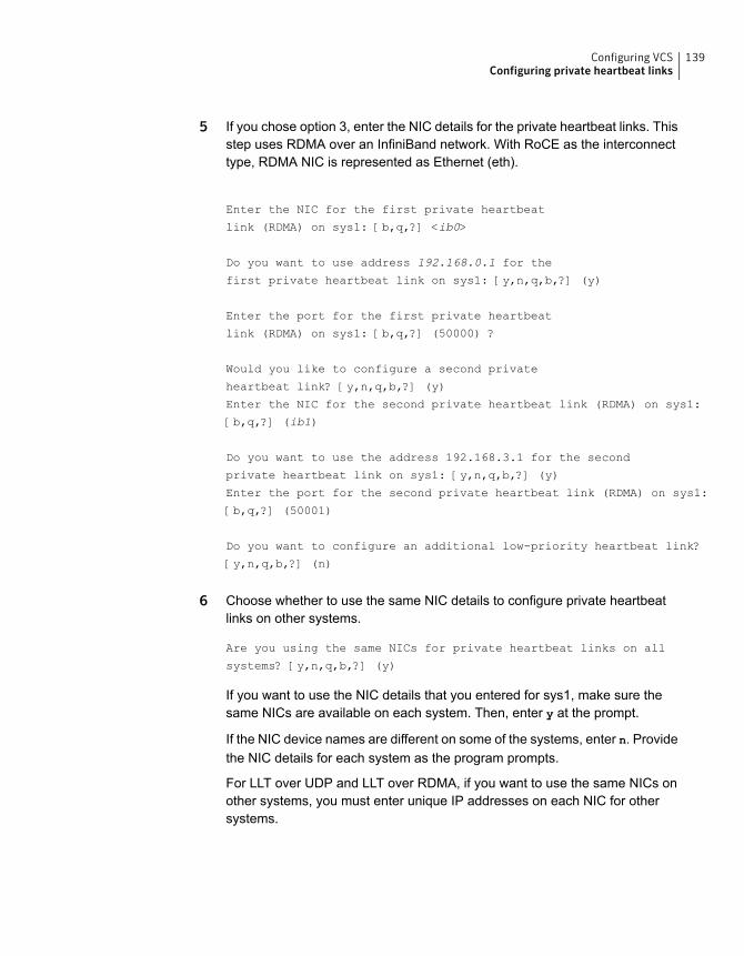
5 If you chose option 3, enter the NIC details for the private heartbeat links. Thisstep uses RDMA over an InfiniBand network. With RoCE as the interconnecttype, RDMA NIC is represented as Ethernet (eth).
Enter the NIC for the first private heartbeat
link (RDMA) on sys1: [b,q,?] <ib0>
Do you want to use address 192.168.0.1 for the
first private heartbeat link on sys1: [y,n,q,b,?] (y)
Enter the port for the first private heartbeat
link (RDMA) on sys1: [b,q,?] (50000) ?
Would you like to configure a second private
heartbeat link? [y,n,q,b,?] (y)
Enter the NIC for the second private heartbeat link (RDMA) on sys1:
[b,q,?] (ib1)
Do you want to use the address 192.168.3.1 for the second
private heartbeat link on sys1: [y,n,q,b,?] (y)
Enter the port for the second private heartbeat link (RDMA) on sys1:
[b,q,?] (50001)
Do you want to configure an additional low-priority heartbeat link?
[y,n,q,b,?] (n)
6 Choose whether to use the same NIC details to configure private heartbeatlinks on other systems.
Are you using the same NICs for private heartbeat links on all
systems? [y,n,q,b,?] (y)
If you want to use the NIC details that you entered for sys1, make sure thesame NICs are available on each system. Then, enter y at the prompt.
If the NIC device names are different on some of the systems, enter n. Providethe NIC details for each system as the program prompts.
For LLT over UDP and LLT over RDMA, if you want to use the same NICs onother systems, you must enter unique IP addresses on each NIC for othersystems.
139Configuring VCSConfiguring private heartbeat links
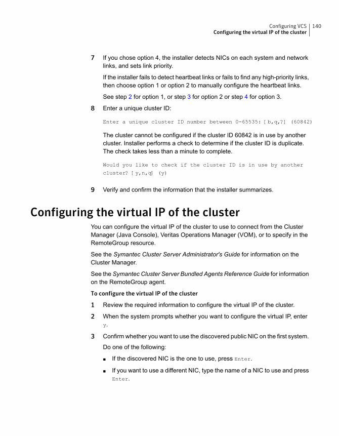
7 If you chose option 4, the installer detects NICs on each system and networklinks, and sets link priority.
If the installer fails to detect heartbeat links or fails to find any high-priority links,then choose option 1 or option 2 to manually configure the heartbeat links.
See step 2 for option 1, or step 3 for option 2 or step 4 for option 3.
8 Enter a unique cluster ID:
Enter a unique cluster ID number between 0-65535: [b,q,?] (60842)
The cluster cannot be configured if the cluster ID 60842 is in use by anothercluster. Installer performs a check to determine if the cluster ID is duplicate.The check takes less than a minute to complete.
Would you like to check if the cluster ID is in use by another
cluster? [y,n,q] (y)
9 Verify and confirm the information that the installer summarizes.
Configuring the virtual IP of the clusterYou can configure the virtual IP of the cluster to use to connect from the ClusterManager (Java Console), Veritas Operations Manager (VOM), or to specify in theRemoteGroup resource.
See the Symantec Cluster Server Administrator's Guide for information on theCluster Manager.
See the Symantec Cluster Server Bundled Agents Reference Guide for informationon the RemoteGroup agent.
To configure the virtual IP of the cluster
1 Review the required information to configure the virtual IP of the cluster.
2 When the system prompts whether you want to configure the virtual IP, entery.
3 Confirm whether you want to use the discovered public NIC on the first system.
Do one of the following:
■ If the discovered NIC is the one to use, press Enter.
■ If you want to use a different NIC, type the name of a NIC to use and pressEnter.
140Configuring VCSConfiguring the virtual IP of the cluster
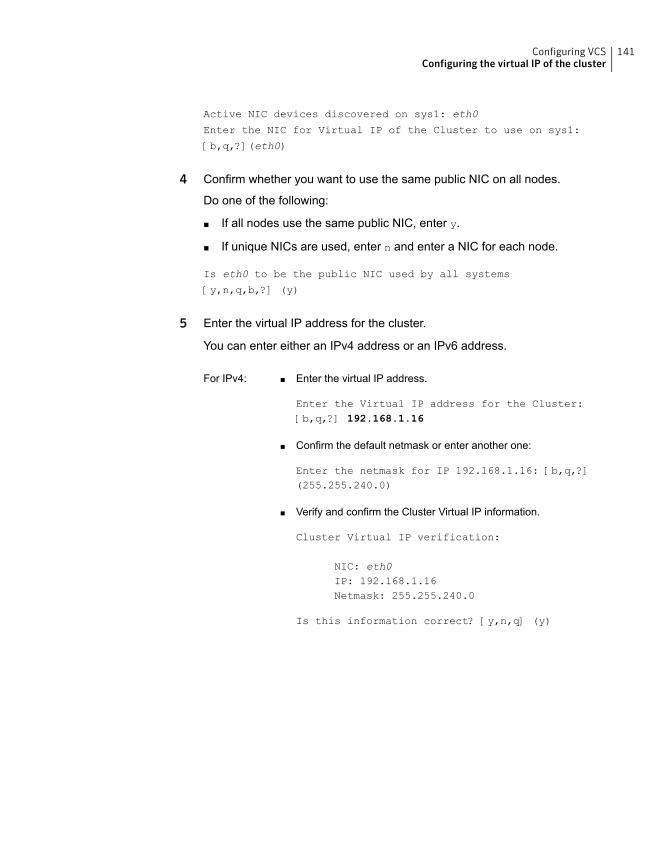
Active NIC devices discovered on sys1: eth0
Enter the NIC for Virtual IP of the Cluster to use on sys1:
[b,q,?](eth0)
4 Confirm whether you want to use the same public NIC on all nodes.
Do one of the following:
■ If all nodes use the same public NIC, enter y.
■ If unique NICs are used, enter n and enter a NIC for each node.
Is eth0 to be the public NIC used by all systems
[y,n,q,b,?] (y)
5 Enter the virtual IP address for the cluster.
You can enter either an IPv4 address or an IPv6 address.
■ Enter the virtual IP address.
Enter the Virtual IP address for the Cluster:[b,q,?] 192.168.1.16
■ Confirm the default netmask or enter another one:
Enter the netmask for IP 192.168.1.16: [b,q,?](255.255.240.0)
■ Verify and confirm the Cluster Virtual IP information.
Cluster Virtual IP verification:
NIC: eth0IP: 192.168.1.16Netmask: 255.255.240.0
Is this information correct? [y,n,q] (y)
For IPv4:
141Configuring VCSConfiguring the virtual IP of the cluster
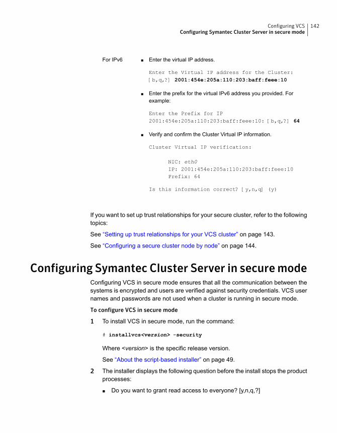
■ Enter the virtual IP address.
Enter the Virtual IP address for the Cluster:[b,q,?] 2001:454e:205a:110:203:baff:feee:10
■ Enter the prefix for the virtual IPv6 address you provided. Forexample:
Enter the Prefix for IP2001:454e:205a:110:203:baff:feee:10: [b,q,?] 64
■ Verify and confirm the Cluster Virtual IP information.
Cluster Virtual IP verification:
NIC: eth0IP: 2001:454e:205a:110:203:baff:feee:10Prefix: 64
Is this information correct? [y,n,q] (y)
For IPv6
If you want to set up trust relationships for your secure cluster, refer to the followingtopics:
See “Setting up trust relationships for your VCS cluster” on page 143.
See “Configuring a secure cluster node by node” on page 144.
Configuring Symantec Cluster Server in securemodeConfiguring VCS in secure mode ensures that all the communication between thesystems is encrypted and users are verified against security credentials. VCS usernames and passwords are not used when a cluster is running in secure mode.
To configure VCS in secure mode
1 To install VCS in secure mode, run the command:
# installvcs<version> -security
Where <version> is the specific release version.
See “About the script-based installer” on page 49.
2 The installer displays the following question before the install stops the productprocesses:
■ Do you want to grant read access to everyone? [y,n,q,?]
142Configuring VCSConfiguring Symantec Cluster Server in secure mode
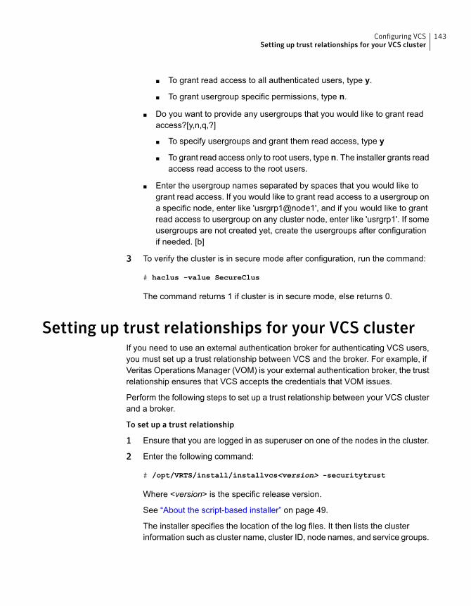
To grant read access to all authenticated users, type y.■
■ To grant usergroup specific permissions, type n.
■ Do you want to provide any usergroups that you would like to grant readaccess?[y,n,q,?]
■ To specify usergroups and grant them read access, type y
■ To grant read access only to root users, type n. The installer grants readaccess read access to the root users.
■ Enter the usergroup names separated by spaces that you would like togrant read access. If you would like to grant read access to a usergroup ona specific node, enter like 'usrgrp1@node1', and if you would like to grantread access to usergroup on any cluster node, enter like 'usrgrp1'. If someusergroups are not created yet, create the usergroups after configurationif needed. [b]
3 To verify the cluster is in secure mode after configuration, run the command:
# haclus -value SecureClus
The command returns 1 if cluster is in secure mode, else returns 0.
Setting up trust relationships for your VCS clusterIf you need to use an external authentication broker for authenticating VCS users,you must set up a trust relationship between VCS and the broker. For example, ifVeritas Operations Manager (VOM) is your external authentication broker, the trustrelationship ensures that VCS accepts the credentials that VOM issues.
Perform the following steps to set up a trust relationship between your VCS clusterand a broker.
To set up a trust relationship
1 Ensure that you are logged in as superuser on one of the nodes in the cluster.
2 Enter the following command:
# /opt/VRTS/install/installvcs<version> -securitytrust
Where <version> is the specific release version.
See “About the script-based installer” on page 49.
The installer specifies the location of the log files. It then lists the clusterinformation such as cluster name, cluster ID, node names, and service groups.
143Configuring VCSSetting up trust relationships for your VCS cluster
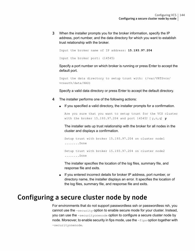
3 When the installer prompts you for the broker information, specify the IPaddress, port number, and the data directory for which you want to establishtrust relationship with the broker.
Input the broker name of IP address: 15.193.97.204
Input the broker port: (14545)
Specify a port number on which broker is running or press Enter to accept thedefault port.
Input the data directory to setup trust with: (/var/VRTSvcs/
vcsauth/data/HAD)
Specify a valid data directory or press Enter to accept the default directory.
4 The installer performs one of the following actions:
■ If you specified a valid directory, the installer prompts for a confirmation.
Are you sure that you want to setup trust for the VCS cluster
with the broker 15.193.97.204 and port 14545? [y,n,q] y
The installer sets up trust relationship with the broker for all nodes in thecluster and displays a confirmation.
Setup trust with broker 15.193.97.204 on cluster node1
........Done
Setup trust with broker 15.193.97.204 on cluster node2
........Done
The installer specifies the location of the log files, summary file, andresponse file and exits.
■ If you entered incorrect details for broker IP address, port number, ordirectory name, the installer displays an error. It specifies the location ofthe log files, summary file, and response file and exits.
Configuring a secure cluster node by nodeFor environments that do not support passwordless ssh or passwordless rsh, youcannot use the -security option to enable secure mode for your cluster. Instead,you can use the -securityonenode option to configure a secure cluster node bynode. Moreover, to enable security in fips mode, use the -fips option together with-securityonenode.
144Configuring VCSConfiguring a secure cluster node by node
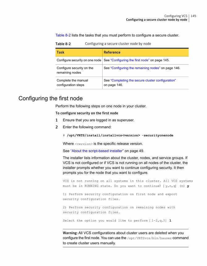
Table 8-2 lists the tasks that you must perform to configure a secure cluster.
Table 8-2 Configuring a secure cluster node by node
ReferenceTask
See “Configuring the first node” on page 145.Configure security on one node
See “Configuring the remaining nodes” on page 146.Configure security on theremaining nodes
See “Completing the secure cluster configuration”on page 146.
Complete the manualconfiguration steps
Configuring the first nodePerform the following steps on one node in your cluster.
To configure security on the first node
1 Ensure that you are logged in as superuser.
2 Enter the following command:
# /opt/VRTS/install/installvcs<version> -securityonenode
Where <version> is the specific release version.
See “About the script-based installer” on page 49.
The installer lists information about the cluster, nodes, and service groups. IfVCS is not configured or if VCS is not running on all nodes of the cluster, theinstaller prompts whether you want to continue configuring security. It thenprompts you for the node that you want to configure.
VCS is not running on all systems in this cluster. All VCS systems
must be in RUNNING state. Do you want to continue? [y,n,q] (n) y
1) Perform security configuration on first node and export
security configuration files.
2) Perform security configuration on remaining nodes with
security configuration files.
Select the option you would like to perform [1-2,q.?] 1
Warning: All VCS configurations about cluster users are deleted when youconfigure the first node. You can use the /opt/VRTSvcs/bin/hauser commandto create cluster users manually.
145Configuring VCSConfiguring a secure cluster node by node
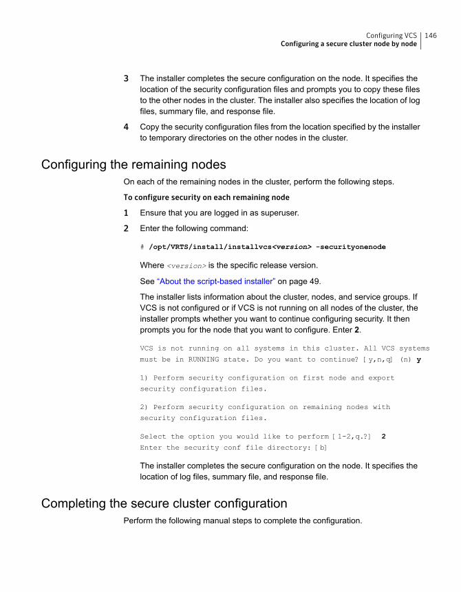
3 The installer completes the secure configuration on the node. It specifies thelocation of the security configuration files and prompts you to copy these filesto the other nodes in the cluster. The installer also specifies the location of logfiles, summary file, and response file.
4 Copy the security configuration files from the location specified by the installerto temporary directories on the other nodes in the cluster.
Configuring the remaining nodesOn each of the remaining nodes in the cluster, perform the following steps.
To configure security on each remaining node
1 Ensure that you are logged in as superuser.
2 Enter the following command:
# /opt/VRTS/install/installvcs<version> -securityonenode
Where <version> is the specific release version.
See “About the script-based installer” on page 49.
The installer lists information about the cluster, nodes, and service groups. IfVCS is not configured or if VCS is not running on all nodes of the cluster, theinstaller prompts whether you want to continue configuring security. It thenprompts you for the node that you want to configure. Enter 2.
VCS is not running on all systems in this cluster. All VCS systems
must be in RUNNING state. Do you want to continue? [y,n,q] (n) y
1) Perform security configuration on first node and export
security configuration files.
2) Perform security configuration on remaining nodes with
security configuration files.
Select the option you would like to perform [1-2,q.?] 2
Enter the security conf file directory: [b]
The installer completes the secure configuration on the node. It specifies thelocation of log files, summary file, and response file.
Completing the secure cluster configurationPerform the following manual steps to complete the configuration.
146Configuring VCSConfiguring a secure cluster node by node
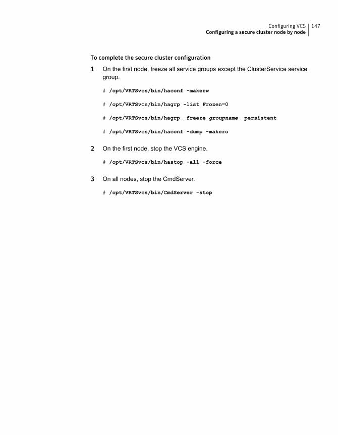
To complete the secure cluster configuration
1 On the first node, freeze all service groups except the ClusterService servicegroup.
# /opt/VRTSvcs/bin/haconf -makerw
# /opt/VRTSvcs/bin/hagrp -list Frozen=0
# /opt/VRTSvcs/bin/hagrp -freeze groupname -persistent
# /opt/VRTSvcs/bin/haconf -dump -makero
2 On the first node, stop the VCS engine.
# /opt/VRTSvcs/bin/hastop -all -force
3 On all nodes, stop the CmdServer.
# /opt/VRTSvcs/bin/CmdServer -stop
147Configuring VCSConfiguring a secure cluster node by node
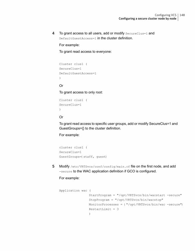
4 To grant access to all users, add or modify SecureClus=1 andDefaultGuestAccess=1 in the cluster definition.
For example:
To grant read access to everyone:
Cluster clus1 (
SecureClus=1
DefaultGuestAccess=1
)
Or
To grant access to only root:
Cluster clus1 (
SecureClus=1
)
Or
To grant read access to specific user groups, add or modify SecureClus=1 andGuestGroups={} to the cluster definition.
For example:
cluster clus1 (
SecureClus=1
GuestGroups={staff, guest}
5 Modify /etc/VRTSvcs/conf/config/main.cf file on the first node, and add-secure to the WAC application definition if GCO is configured.
For example:
Application wac (
StartProgram = "/opt/VRTSvcs/bin/wacstart -secure"
StopProgram = "/opt/VRTSvcs/bin/wacstop"
MonitorProcesses = {"/opt/VRTSvcs/bin/wac -secure"}
RestartLimit = 3
)
148Configuring VCSConfiguring a secure cluster node by node
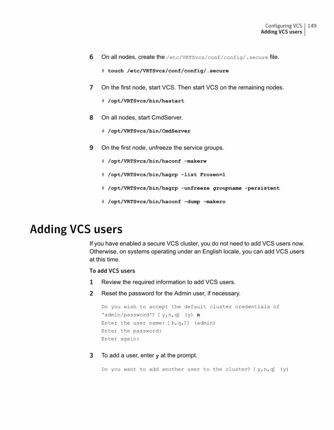
6 On all nodes, create the /etc/VRTSvcs/conf/config/.secure file.
# touch /etc/VRTSvcs/conf/config/.secure
7 On the first node, start VCS. Then start VCS on the remaining nodes.
# /opt/VRTSvcs/bin/hastart
8 On all nodes, start CmdServer.
# /opt/VRTSvcs/bin/CmdServer
9 On the first node, unfreeze the service groups.
# /opt/VRTSvcs/bin/haconf -makerw
# /opt/VRTSvcs/bin/hagrp -list Frozen=1
# /opt/VRTSvcs/bin/hagrp -unfreeze groupname -persistent
# /opt/VRTSvcs/bin/haconf -dump -makero
Adding VCS usersIf you have enabled a secure VCS cluster, you do not need to add VCS users now.Otherwise, on systems operating under an English locale, you can add VCS usersat this time.
To add VCS users
1 Review the required information to add VCS users.
2 Reset the password for the Admin user, if necessary.
Do you wish to accept the default cluster credentials of
'admin/password'? [y,n,q] (y) n
Enter the user name: [b,q,?] (admin)
Enter the password:
Enter again:
3 To add a user, enter y at the prompt.
Do you want to add another user to the cluster? [y,n,q] (y)
149Configuring VCSAdding VCS users
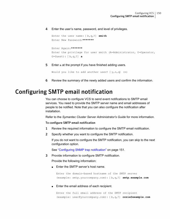
4 Enter the user’s name, password, and level of privileges.
Enter the user name: [b,q,?] smith
Enter New Password:*******
Enter Again:*******
Enter the privilege for user smith (A=Administrator, O=Operator,
G=Guest): [b,q,?] a
5 Enter n at the prompt if you have finished adding users.
Would you like to add another user? [y,n,q] (n)
6 Review the summary of the newly added users and confirm the information.
Configuring SMTP email notificationYou can choose to configure VCS to send event notifications to SMTP emailservices. You need to provide the SMTP server name and email addresses ofpeople to be notified. Note that you can also configure the notification afterinstallation.
Refer to the Symantec Cluster Server Administrator's Guide for more information.
To configure SMTP email notification
1 Review the required information to configure the SMTP email notification.
2 Specify whether you want to configure the SMTP notification.
If you do not want to configure the SMTP notification, you can skip to the nextconfiguration option.
See “Configuring SNMP trap notification” on page 151.
3 Provide information to configure SMTP notification.
Provide the following information:
■ Enter the SMTP server’s host name.
Enter the domain-based hostname of the SMTP server
(example: smtp.yourcompany.com): [b,q,?] smtp.example.com
■ Enter the email address of each recipient.
Enter the full email address of the SMTP recipient
(example: [email protected]): [b,q,?] [email protected]
150Configuring VCSConfiguring SMTP email notification
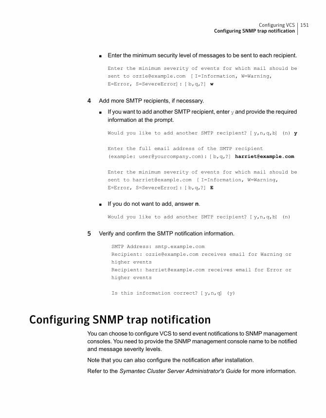
■ Enter the minimum security level of messages to be sent to each recipient.
Enter the minimum severity of events for which mail should be
sent to [email protected] [I=Information, W=Warning,
E=Error, S=SevereError]: [b,q,?] w
4 Add more SMTP recipients, if necessary.
■ If you want to add another SMTP recipient, enter y and provide the requiredinformation at the prompt.
Would you like to add another SMTP recipient? [y,n,q,b] (n) y
Enter the full email address of the SMTP recipient
(example: [email protected]): [b,q,?] [email protected]
Enter the minimum severity of events for which mail should be
sent to [email protected] [I=Information, W=Warning,
E=Error, S=SevereError]: [b,q,?] E
■ If you do not want to add, answer n.
Would you like to add another SMTP recipient? [y,n,q,b] (n)
5 Verify and confirm the SMTP notification information.
SMTP Address: smtp.example.com
Recipient: [email protected] receives email for Warning or
higher events
Recipient: [email protected] receives email for Error or
higher events
Is this information correct? [y,n,q] (y)
Configuring SNMP trap notificationYou can choose to configure VCS to send event notifications to SNMP managementconsoles. You need to provide the SNMP management console name to be notifiedand message severity levels.
Note that you can also configure the notification after installation.
Refer to the Symantec Cluster Server Administrator's Guide for more information.
151Configuring VCSConfiguring SNMP trap notification
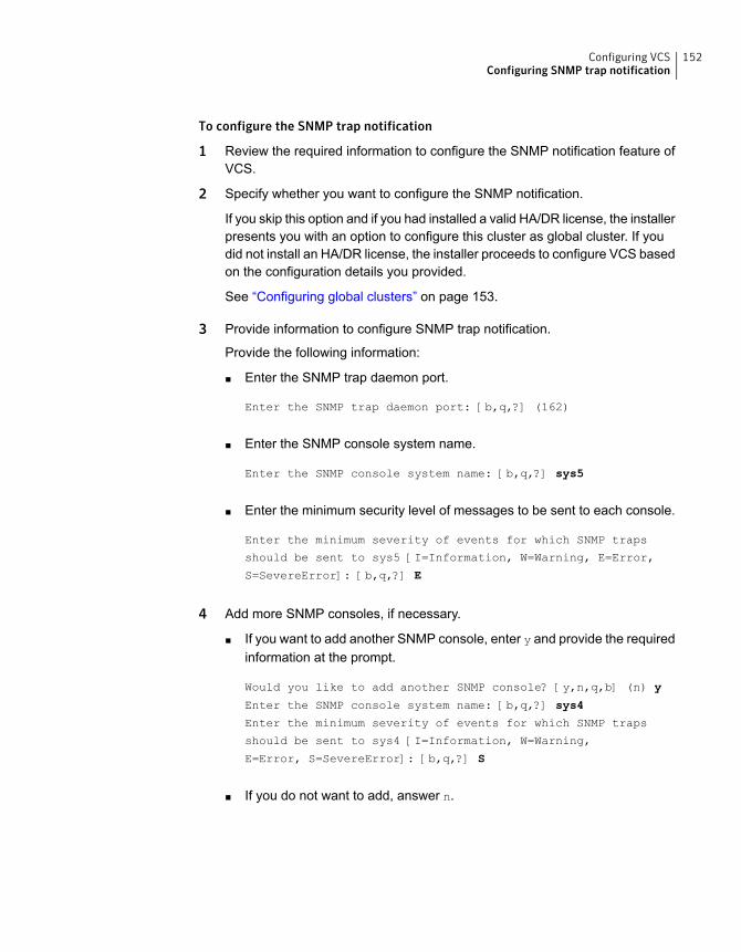
To configure the SNMP trap notification
1 Review the required information to configure the SNMP notification feature ofVCS.
2 Specify whether you want to configure the SNMP notification.
If you skip this option and if you had installed a valid HA/DR license, the installerpresents you with an option to configure this cluster as global cluster. If youdid not install an HA/DR license, the installer proceeds to configure VCS basedon the configuration details you provided.
See “Configuring global clusters” on page 153.
3 Provide information to configure SNMP trap notification.
Provide the following information:
■ Enter the SNMP trap daemon port.
Enter the SNMP trap daemon port: [b,q,?] (162)
■ Enter the SNMP console system name.
Enter the SNMP console system name: [b,q,?] sys5
■ Enter the minimum security level of messages to be sent to each console.
Enter the minimum severity of events for which SNMP traps
should be sent to sys5 [I=Information, W=Warning, E=Error,
S=SevereError]: [b,q,?] E
4 Add more SNMP consoles, if necessary.
■ If you want to add another SNMP console, enter y and provide the requiredinformation at the prompt.
Would you like to add another SNMP console? [y,n,q,b] (n) y
Enter the SNMP console system name: [b,q,?] sys4
Enter the minimum severity of events for which SNMP traps
should be sent to sys4 [I=Information, W=Warning,
E=Error, S=SevereError]: [b,q,?] S
■ If you do not want to add, answer n.
152Configuring VCSConfiguring SNMP trap notification
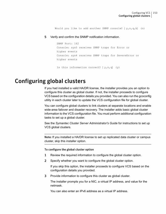
Would you like to add another SNMP console? [y,n,q,b] (n)
5 Verify and confirm the SNMP notification information.
SNMP Port: 162
Console: sys5 receives SNMP traps for Error or
higher events
Console: sys4 receives SNMP traps for SevereError or
higher events
Is this information correct? [y,n,q] (y)
Configuring global clustersIf you had installed a valid HA/DR license, the installer provides you an option toconfigure this cluster as global cluster. If not, the installer proceeds to configureVCS based on the configuration details you provided. You can also run the gcoconfigutility in each cluster later to update the VCS configuration file for global cluster.
You can configure global clusters to link clusters at separate locations and enablewide-area failover and disaster recovery. The installer adds basic global clusterinformation to the VCS configuration file. You must perform additional configurationtasks to set up a global cluster.
See the Symantec Cluster Server Administrator's Guide for instructions to set upVCS global clusters.
Note: If you installed a HA/DR license to set up replicated data cluster or campuscluster, skip this installer option.
To configure the global cluster option
1 Review the required information to configure the global cluster option.
2 Specify whether you want to configure the global cluster option.
If you skip this option, the installer proceeds to configure VCS based on theconfiguration details you provided.
3 Provide information to configure this cluster as global cluster.
The installer prompts you for a NIC, a virtual IP address, and value for thenetmask.
You can also enter an IPv6 address as a virtual IP address.
153Configuring VCSConfiguring global clusters
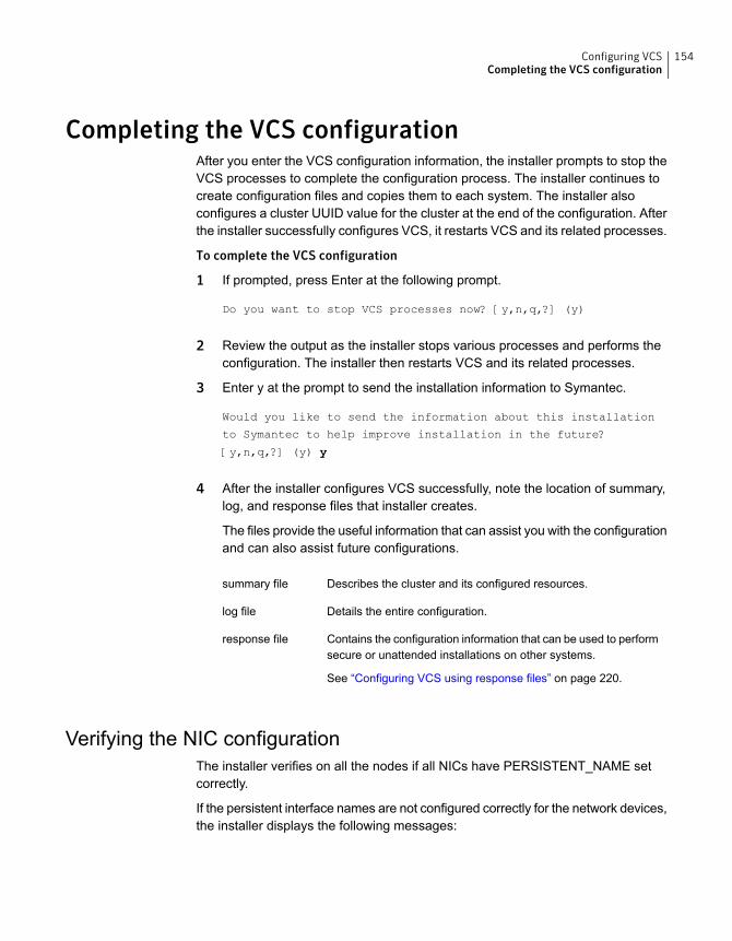
Completing the VCS configurationAfter you enter the VCS configuration information, the installer prompts to stop theVCS processes to complete the configuration process. The installer continues tocreate configuration files and copies them to each system. The installer alsoconfigures a cluster UUID value for the cluster at the end of the configuration. Afterthe installer successfully configures VCS, it restarts VCS and its related processes.
To complete the VCS configuration
1 If prompted, press Enter at the following prompt.
Do you want to stop VCS processes now? [y,n,q,?] (y)
2 Review the output as the installer stops various processes and performs theconfiguration. The installer then restarts VCS and its related processes.
3 Enter y at the prompt to send the installation information to Symantec.
Would you like to send the information about this installation
to Symantec to help improve installation in the future?
[y,n,q,?] (y) y
4 After the installer configures VCS successfully, note the location of summary,log, and response files that installer creates.
The files provide the useful information that can assist you with the configurationand can also assist future configurations.
Describes the cluster and its configured resources.summary file
Details the entire configuration.log file
Contains the configuration information that can be used to performsecure or unattended installations on other systems.
See “Configuring VCS using response files” on page 220.
response file
Verifying the NIC configurationThe installer verifies on all the nodes if all NICs have PERSISTENT_NAME setcorrectly.
If the persistent interface names are not configured correctly for the network devices,the installer displays the following messages:
154Configuring VCSCompleting the VCS configuration
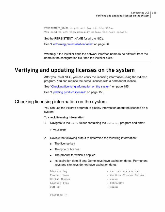
PERSISTENT_NAME is not set for all the NICs.
You need to set them manually before the next reboot.
Set the PERSISTENT_NAME for all the NICs.
See “Performing preinstallation tasks” on page 66.
Warning: If the installer finds the network interface name to be different from thename in the configuration file, then the installer exits.
Verifying and updating licenses on the systemAfter you install VCS, you can verify the licensing information using the vxlicrepprogram. You can replace the demo licenses with a permanent license.
See “Checking licensing information on the system” on page 155.
See “Updating product licenses” on page 156.
Checking licensing information on the systemYou can use the vxlicrep program to display information about the licenses on asystem.
To check licensing information
1 Navigate to the /sbin folder containing the vxlicrep program and enter:
# vxlicrep
2 Review the following output to determine the following information:
■ The license key
■ The type of license
■ The product for which it applies
■ Its expiration date, if any. Demo keys have expiration dates. Permanentkeys and site keys do not have expiration dates.
License Key = xxx-xxx-xxx-xxx-xxx
Product Name = Veritas Cluster Server
Serial Number = xxxxx
License Type = PERMANENT
OEM ID = xxxxx
Features :=
155Configuring VCSVerifying and updating licenses on the system
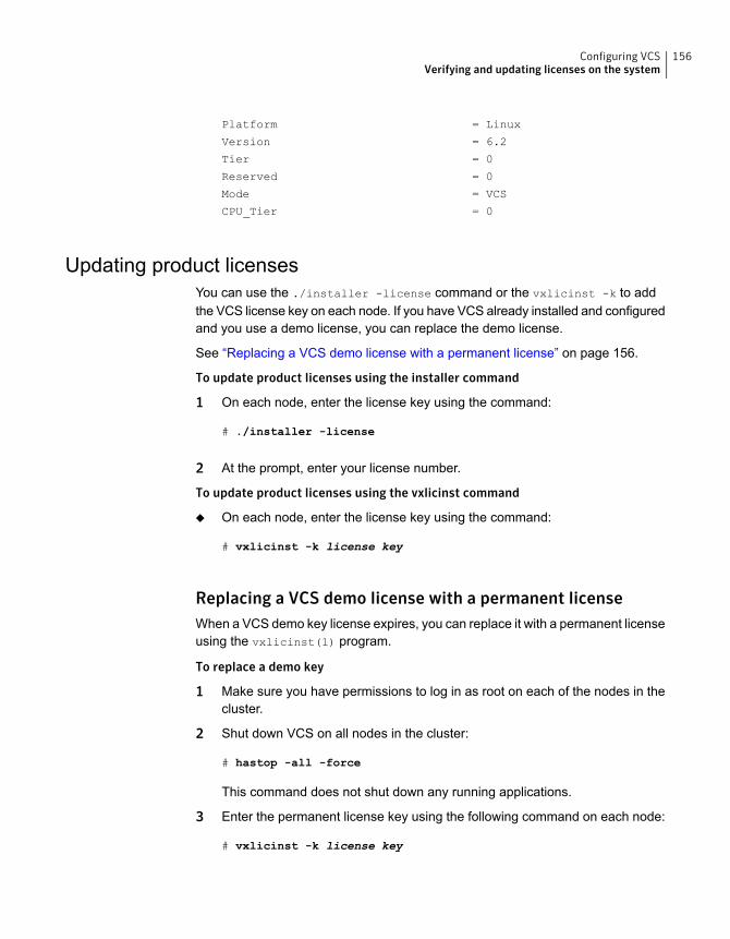
Platform = Linux
Version = 6.2
Tier = 0
Reserved = 0
Mode = VCS
CPU_Tier = 0
Updating product licensesYou can use the ./installer -license command or the vxlicinst -k to addthe VCS license key on each node. If you have VCS already installed and configuredand you use a demo license, you can replace the demo license.
See “Replacing a VCS demo license with a permanent license” on page 156.
To update product licenses using the installer command
1 On each node, enter the license key using the command:
# ./installer -license
2 At the prompt, enter your license number.
To update product licenses using the vxlicinst command
◆ On each node, enter the license key using the command:
# vxlicinst -k license key
Replacing a VCS demo license with a permanent licenseWhen a VCS demo key license expires, you can replace it with a permanent licenseusing the vxlicinst(1) program.
To replace a demo key
1 Make sure you have permissions to log in as root on each of the nodes in thecluster.
2 Shut down VCS on all nodes in the cluster:
# hastop -all -force
This command does not shut down any running applications.
3 Enter the permanent license key using the following command on each node:
# vxlicinst -k license key
156Configuring VCSVerifying and updating licenses on the system

4 Make sure demo licenses are replaced on all cluster nodes before startingVCS.
# vxlicrep
5 Start VCS on each node:
# hastart
157Configuring VCSVerifying and updating licenses on the system

Configuring VCS clustersfor data integrity
This chapter includes the following topics:
■ Setting up disk-based I/O fencing using installvcs
■ Setting up server-based I/O fencing using installvcs
■ Setting up non-SCSI-3 I/O fencing in virtual environments using installvcs
■ Setting up majority-based I/O fencing using installvcs
■ Enabling or disabling the preferred fencing policy
Setting up disk-based I/O fencing using installvcsYou can configure I/O fencing using the -fencing option of the installvcs.
Initializing disks as VxVM disksPerform the following procedure to initialize disks as VxVM disks.
To initialize disks as VxVM disks
1 List the new external disks or the LUNs as recognized by the operating system.On each node, enter:
# fdisk -l
2 To initialize the disks as VxVM disks, use one of the following methods:
■ Use the interactive vxdiskadm utility to initialize the disks as VxVM disks.
9Chapter
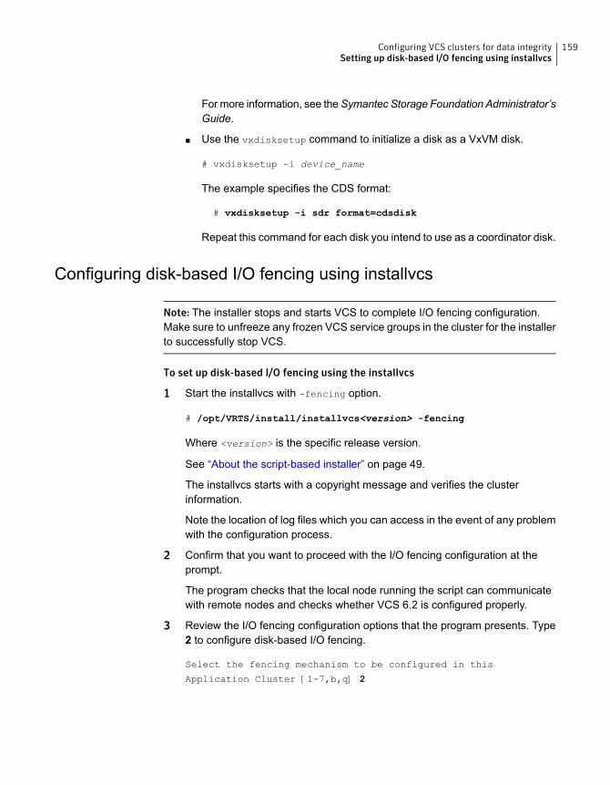
For more information, see theSymantec Storage Foundation Administrator’sGuide.
■ Use the vxdisksetup command to initialize a disk as a VxVM disk.
# vxdisksetup -i device_name
The example specifies the CDS format:
# vxdisksetup -i sdr format=cdsdisk
Repeat this command for each disk you intend to use as a coordinator disk.
Configuring disk-based I/O fencing using installvcs
Note: The installer stops and starts VCS to complete I/O fencing configuration.Make sure to unfreeze any frozen VCS service groups in the cluster for the installerto successfully stop VCS.
To set up disk-based I/O fencing using the installvcs
1 Start the installvcs with -fencing option.
# /opt/VRTS/install/installvcs<version> -fencing
Where <version> is the specific release version.
See “About the script-based installer” on page 49.
The installvcs starts with a copyright message and verifies the clusterinformation.
Note the location of log files which you can access in the event of any problemwith the configuration process.
2 Confirm that you want to proceed with the I/O fencing configuration at theprompt.
The program checks that the local node running the script can communicatewith remote nodes and checks whether VCS 6.2 is configured properly.
3 Review the I/O fencing configuration options that the program presents. Type2 to configure disk-based I/O fencing.
Select the fencing mechanism to be configured in this
Application Cluster [1-7,b,q] 2
159Configuring VCS clusters for data integritySetting up disk-based I/O fencing using installvcs
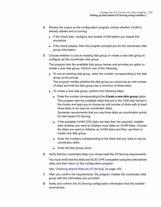
4 Review the output as the configuration program checks whether VxVM isalready started and is running.
■ If the check fails, configure and enable VxVM before you repeat thisprocedure.
■ If the check passes, then the program prompts you for the coordinator diskgroup information.
5 Choose whether to use an existing disk group or create a new disk group toconfigure as the coordinator disk group.
The program lists the available disk group names and provides an option tocreate a new disk group. Perform one of the following:
■ To use an existing disk group, enter the number corresponding to the diskgroup at the prompt.The program verifies whether the disk group you chose has an odd numberof disks and that the disk group has a minimum of three disks.
■ To create a new disk group, perform the following steps:
■ Enter the number corresponding to theCreate a new disk group option.The program lists the available disks that are in the CDS disk format inthe cluster and asks you to choose an odd number of disks with at leastthree disks to be used as coordinator disks.Symantec recommends that you use three disks as coordination pointsfor disk-based I/O fencing.
■ If the available VxVM CDS disks are less than the required, installerasks whether you want to initialize more disks as VxVM disks. Choosethe disks you want to initialize as VxVM disks and then use them tocreate new disk group.
■ Enter the numbers corresponding to the disks that you want to use ascoordinator disks.
■ Enter the disk group name.
6 Verify that the coordinator disks you chose meet the I/O fencing requirements.
You must verify that the disks are SCSI-3 PR compatible using the vxfentsthdwutility and then return to this configuration program.
See “Checking shared disks for I/O fencing” on page 163.
7 After you confirm the requirements, the program creates the coordinator diskgroup with the information you provided.
8 Verify and confirm the I/O fencing configuration information that the installersummarizes.
160Configuring VCS clusters for data integritySetting up disk-based I/O fencing using installvcs
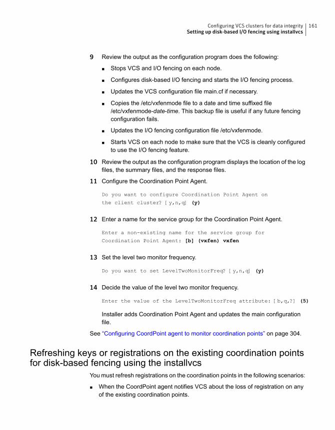
9 Review the output as the configuration program does the following:
■ Stops VCS and I/O fencing on each node.
■ Configures disk-based I/O fencing and starts the I/O fencing process.
■ Updates the VCS configuration file main.cf if necessary.
■ Copies the /etc/vxfenmode file to a date and time suffixed file/etc/vxfenmode-date-time. This backup file is useful if any future fencingconfiguration fails.
■ Updates the I/O fencing configuration file /etc/vxfenmode.
■ Starts VCS on each node to make sure that the VCS is cleanly configuredto use the I/O fencing feature.
10 Review the output as the configuration program displays the location of the logfiles, the summary files, and the response files.
11 Configure the Coordination Point Agent.
Do you want to configure Coordination Point Agent on
the client cluster? [y,n,q] (y)
12 Enter a name for the service group for the Coordination Point Agent.
Enter a non-existing name for the service group for
Coordination Point Agent: [b] (vxfen) vxfen
13 Set the level two monitor frequency.
Do you want to set LevelTwoMonitorFreq? [y,n,q] (y)
14 Decide the value of the level two monitor frequency.
Enter the value of the LevelTwoMonitorFreq attribute: [b,q,?] (5)
Installer adds Coordination Point Agent and updates the main configurationfile.
See “Configuring CoordPoint agent to monitor coordination points” on page 304.
Refreshing keys or registrations on the existing coordination pointsfor disk-based fencing using the installvcs
You must refresh registrations on the coordination points in the following scenarios:
■ When the CoordPoint agent notifies VCS about the loss of registration on anyof the existing coordination points.
161Configuring VCS clusters for data integritySetting up disk-based I/O fencing using installvcs
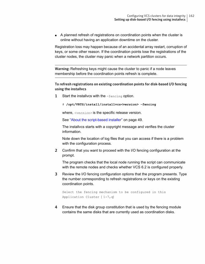
■ A planned refresh of registrations on coordination points when the cluster isonline without having an application downtime on the cluster.
Registration loss may happen because of an accidental array restart, corruption ofkeys, or some other reason. If the coordination points lose the registrations of thecluster nodes, the cluster may panic when a network partition occurs.
Warning: Refreshing keys might cause the cluster to panic if a node leavesmembership before the coordination points refresh is complete.
To refresh registrations on existing coordination points for disk-based I/O fencingusing the installvcs
1 Start the installvcs with the -fencing option.
# /opt/VRTS/install/installvcs<version> -fencing
where, <version> is the specific release version.
See “About the script-based installer” on page 49.
The installvcs starts with a copyright message and verifies the clusterinformation.
Note down the location of log files that you can access if there is a problemwith the configuration process.
2 Confirm that you want to proceed with the I/O fencing configuration at theprompt.
The program checks that the local node running the script can communicatewith the remote nodes and checks whether VCS 6.2 is configured properly.
3 Review the I/O fencing configuration options that the program presents. Typethe number corresponding to refresh registrations or keys on the existingcoordination points.
Select the fencing mechanism to be configured in this
Application Cluster [1-7,q]
4 Ensure that the disk group constitution that is used by the fencing modulecontains the same disks that are currently used as coordination disks.
162Configuring VCS clusters for data integritySetting up disk-based I/O fencing using installvcs
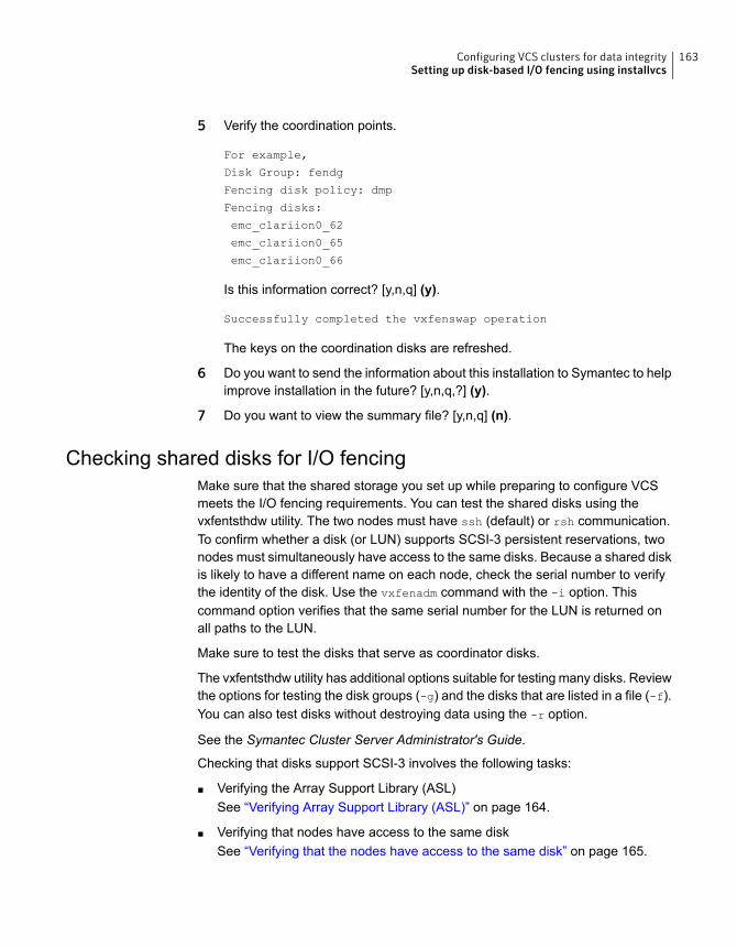
5 Verify the coordination points.
For example,
Disk Group: fendg
Fencing disk policy: dmp
Fencing disks:
emc_clariion0_62
emc_clariion0_65
emc_clariion0_66
Is this information correct? [y,n,q] (y).
Successfully completed the vxfenswap operation
The keys on the coordination disks are refreshed.
6 Do you want to send the information about this installation to Symantec to helpimprove installation in the future? [y,n,q,?] (y).
7 Do you want to view the summary file? [y,n,q] (n).
Checking shared disks for I/O fencingMake sure that the shared storage you set up while preparing to configure VCSmeets the I/O fencing requirements. You can test the shared disks using thevxfentsthdw utility. The two nodes must have ssh (default) or rsh communication.To confirm whether a disk (or LUN) supports SCSI-3 persistent reservations, twonodes must simultaneously have access to the same disks. Because a shared diskis likely to have a different name on each node, check the serial number to verifythe identity of the disk. Use the vxfenadm command with the -i option. Thiscommand option verifies that the same serial number for the LUN is returned onall paths to the LUN.
Make sure to test the disks that serve as coordinator disks.
The vxfentsthdw utility has additional options suitable for testing many disks. Reviewthe options for testing the disk groups (-g) and the disks that are listed in a file (-f).You can also test disks without destroying data using the -r option.
See the Symantec Cluster Server Administrator's Guide.
Checking that disks support SCSI-3 involves the following tasks:
■ Verifying the Array Support Library (ASL)See “Verifying Array Support Library (ASL)” on page 164.
■ Verifying that nodes have access to the same diskSee “Verifying that the nodes have access to the same disk” on page 165.
163Configuring VCS clusters for data integritySetting up disk-based I/O fencing using installvcs
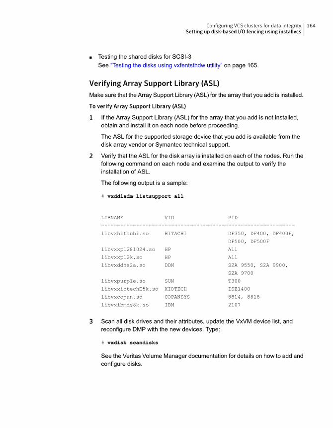
■ Testing the shared disks for SCSI-3See “Testing the disks using vxfentsthdw utility” on page 165.
Verifying Array Support Library (ASL)Make sure that the Array Support Library (ASL) for the array that you add is installed.
To verify Array Support Library (ASL)
1 If the Array Support Library (ASL) for the array that you add is not installed,obtain and install it on each node before proceeding.
The ASL for the supported storage device that you add is available from thedisk array vendor or Symantec technical support.
2 Verify that the ASL for the disk array is installed on each of the nodes. Run thefollowing command on each node and examine the output to verify theinstallation of ASL.
The following output is a sample:
# vxddladm listsupport all
LIBNAME VID PID
=============================================================
libvxhitachi.so HITACHI DF350, DF400, DF400F,
DF500, DF500F
libvxxp1281024.so HP All
libvxxp12k.so HP All
libvxddns2a.so DDN S2A 9550, S2A 9900,
S2A 9700
libvxpurple.so SUN T300
libvxxiotechE5k.so XIOTECH ISE1400
libvxcopan.so COPANSYS 8814, 8818
libvxibmds8k.so IBM 2107
3 Scan all disk drives and their attributes, update the VxVM device list, andreconfigure DMP with the new devices. Type:
# vxdisk scandisks
See the Veritas Volume Manager documentation for details on how to add andconfigure disks.
164Configuring VCS clusters for data integritySetting up disk-based I/O fencing using installvcs
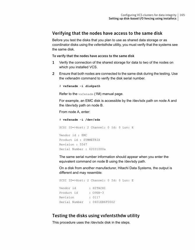
Verifying that the nodes have access to the same diskBefore you test the disks that you plan to use as shared data storage or ascoordinator disks using the vxfentsthdw utility, you must verify that the systems seethe same disk.
To verify that the nodes have access to the same disk
1 Verify the connection of the shared storage for data to two of the nodes onwhich you installed VCS.
2 Ensure that both nodes are connected to the same disk during the testing. Usethe vxfenadm command to verify the disk serial number.
# vxfenadm -i diskpath
Refer to the vxfenadm (1M) manual page.
For example, an EMC disk is accessible by the /dev/sdx path on node A andthe /dev/sdy path on node B.
From node A, enter:
# vxfenadm -i /dev/sdx
SCSI ID=>Host: 2 Channel: 0 Id: 0 Lun: E
Vendor id : EMC
Product id : SYMMETRIX
Revision : 5567
Serial Number : 42031000a
The same serial number information should appear when you enter theequivalent command on node B using the /dev/sdy path.
On a disk from another manufacturer, Hitachi Data Systems, the output isdifferent and may resemble:
SCSI ID=>Host: 2 Channel: 0 Id: 0 Lun: E
Vendor id : HITACHI
Product id : OPEN-3
Revision : 0117
Serial Number : 0401EB6F0002
Testing the disks using vxfentsthdw utilityThis procedure uses the /dev/sdx disk in the steps.
165Configuring VCS clusters for data integritySetting up disk-based I/O fencing using installvcs
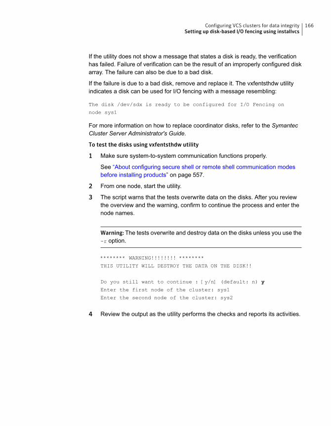
If the utility does not show a message that states a disk is ready, the verificationhas failed. Failure of verification can be the result of an improperly configured diskarray. The failure can also be due to a bad disk.
If the failure is due to a bad disk, remove and replace it. The vxfentsthdw utilityindicates a disk can be used for I/O fencing with a message resembling:
The disk /dev/sdx is ready to be configured for I/O Fencing on
node sys1
For more information on how to replace coordinator disks, refer to the SymantecCluster Server Administrator's Guide.
To test the disks using vxfentsthdw utility
1 Make sure system-to-system communication functions properly.
See “About configuring secure shell or remote shell communication modesbefore installing products” on page 557.
2 From one node, start the utility.
3 The script warns that the tests overwrite data on the disks. After you reviewthe overview and the warning, confirm to continue the process and enter thenode names.
Warning: The tests overwrite and destroy data on the disks unless you use the-r option.
******** WARNING!!!!!!!! ********
THIS UTILITY WILL DESTROY THE DATA ON THE DISK!!
Do you still want to continue : [y/n] (default: n) y
Enter the first node of the cluster: sys1
Enter the second node of the cluster: sys2
4 Review the output as the utility performs the checks and reports its activities.
166Configuring VCS clusters for data integritySetting up disk-based I/O fencing using installvcs
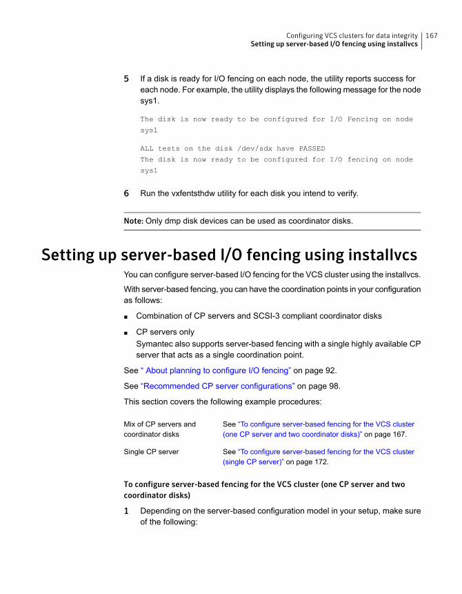
5 If a disk is ready for I/O fencing on each node, the utility reports success foreach node. For example, the utility displays the following message for the nodesys1.
The disk is now ready to be configured for I/O Fencing on node
sys1
ALL tests on the disk /dev/sdx have PASSED
The disk is now ready to be configured for I/O fencing on node
sys1
6 Run the vxfentsthdw utility for each disk you intend to verify.
Note: Only dmp disk devices can be used as coordinator disks.
Setting up server-based I/O fencing using installvcsYou can configure server-based I/O fencing for the VCS cluster using the installvcs.
With server-based fencing, you can have the coordination points in your configurationas follows:
■ Combination of CP servers and SCSI-3 compliant coordinator disks
■ CP servers onlySymantec also supports server-based fencing with a single highly available CPserver that acts as a single coordination point.
See “ About planning to configure I/O fencing” on page 92.
See “Recommended CP server configurations” on page 98.
This section covers the following example procedures:
See “To configure server-based fencing for the VCS cluster(one CP server and two coordinator disks)” on page 167.
Mix of CP servers andcoordinator disks
See “To configure server-based fencing for the VCS cluster(single CP server)” on page 172.
Single CP server
To configure server-based fencing for the VCS cluster (one CP server and twocoordinator disks)
1 Depending on the server-based configuration model in your setup, make sureof the following:
167Configuring VCS clusters for data integritySetting up server-based I/O fencing using installvcs
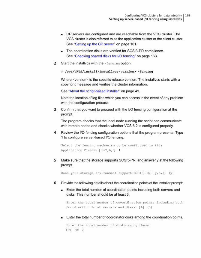
■ CP servers are configured and are reachable from the VCS cluster. TheVCS cluster is also referred to as the application cluster or the client cluster.See “Setting up the CP server” on page 101.
■ The coordination disks are verified for SCSI3-PR compliance.See “Checking shared disks for I/O fencing” on page 163.
2 Start the installvcs with the -fencing option.
# /opt/VRTS/install/installvcs<version> -fencing
Where <version> is the specific release version. The installvcs starts with acopyright message and verifies the cluster information.
See “About the script-based installer” on page 49.
Note the location of log files which you can access in the event of any problemwith the configuration process.
3 Confirm that you want to proceed with the I/O fencing configuration at theprompt.
The program checks that the local node running the script can communicatewith remote nodes and checks whether VCS 6.2 is configured properly.
4 Review the I/O fencing configuration options that the program presents. Type1 to configure server-based I/O fencing.
Select the fencing mechanism to be configured in this
Application Cluster [1-7,b,q] 1
5 Make sure that the storage supports SCSI3-PR, and answer y at the followingprompt.
Does your storage environment support SCSI3 PR? [y,n,q] (y)
6 Provide the following details about the coordination points at the installer prompt:
■ Enter the total number of coordination points including both servers anddisks. This number should be at least 3.
Enter the total number of co-ordination points including both
Coordination Point servers and disks: [b] (3)
■ Enter the total number of coordinator disks among the coordination points.
Enter the total number of disks among these:
[b] (0) 2
168Configuring VCS clusters for data integritySetting up server-based I/O fencing using installvcs
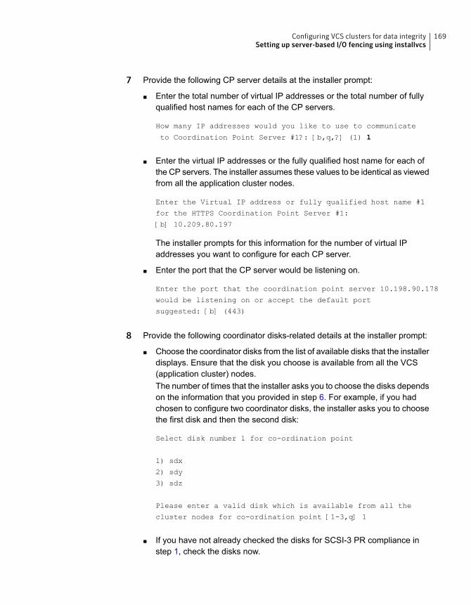
7 Provide the following CP server details at the installer prompt:
■ Enter the total number of virtual IP addresses or the total number of fullyqualified host names for each of the CP servers.
How many IP addresses would you like to use to communicate
to Coordination Point Server #1?: [b,q,?] (1) 1
■ Enter the virtual IP addresses or the fully qualified host name for each ofthe CP servers. The installer assumes these values to be identical as viewedfrom all the application cluster nodes.
Enter the Virtual IP address or fully qualified host name #1
for the HTTPS Coordination Point Server #1:
[b] 10.209.80.197
The installer prompts for this information for the number of virtual IPaddresses you want to configure for each CP server.
■ Enter the port that the CP server would be listening on.
Enter the port that the coordination point server 10.198.90.178
would be listening on or accept the default port
suggested: [b] (443)
8 Provide the following coordinator disks-related details at the installer prompt:
■ Choose the coordinator disks from the list of available disks that the installerdisplays. Ensure that the disk you choose is available from all the VCS(application cluster) nodes.The number of times that the installer asks you to choose the disks dependson the information that you provided in step 6. For example, if you hadchosen to configure two coordinator disks, the installer asks you to choosethe first disk and then the second disk:
Select disk number 1 for co-ordination point
1) sdx
2) sdy
3) sdz
Please enter a valid disk which is available from all the
cluster nodes for co-ordination point [1-3,q] 1
■ If you have not already checked the disks for SCSI-3 PR compliance instep 1, check the disks now.
169Configuring VCS clusters for data integritySetting up server-based I/O fencing using installvcs
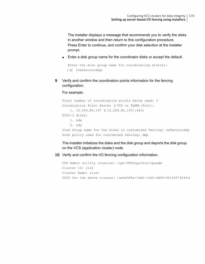
The installer displays a message that recommends you to verify the disksin another window and then return to this configuration procedure.Press Enter to continue, and confirm your disk selection at the installerprompt.
■ Enter a disk group name for the coordinator disks or accept the default.
Enter the disk group name for coordinating disk(s):
[b] (vxfencoorddg)
9 Verify and confirm the coordination points information for the fencingconfiguration.
For example:
Total number of coordination points being used: 3
Coordination Point Server ([VIP or FQHN]:Port):
1. 10.209.80.197 ([10.209.80.197]:443)
SCSI-3 disks:
1. sdx
2. sdy
Disk Group name for the disks in customized fencing: vxfencoorddg
Disk policy used for customized fencing: dmp
The installer initializes the disks and the disk group and deports the disk groupon the VCS (application cluster) node.
10 Verify and confirm the I/O fencing configuration information.
CPS Admin utility location: /opt/VRTScps/bin/cpsadm
Cluster ID: 2122
Cluster Name: clus1
UUID for the above cluster: {ae5e589a-1dd1-11b2-dd44-00144f79240c}
170Configuring VCS clusters for data integritySetting up server-based I/O fencing using installvcs
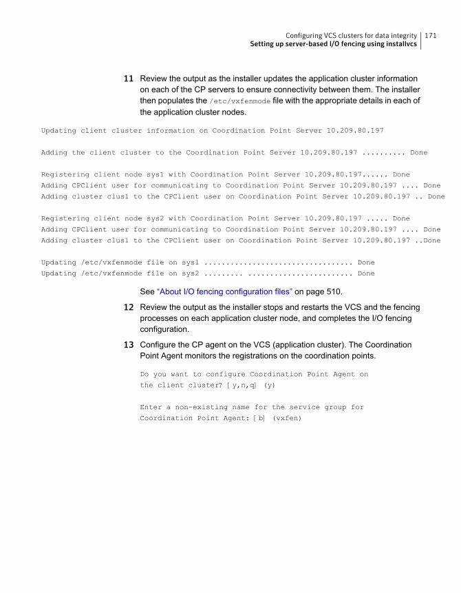
11 Review the output as the installer updates the application cluster informationon each of the CP servers to ensure connectivity between them. The installerthen populates the /etc/vxfenmode file with the appropriate details in each ofthe application cluster nodes.
Updating client cluster information on Coordination Point Server 10.209.80.197
Adding the client cluster to the Coordination Point Server 10.209.80.197 .......... Done
Registering client node sys1 with Coordination Point Server 10.209.80.197...... Done
Adding CPClient user for communicating to Coordination Point Server 10.209.80.197 .... Done
Adding cluster clus1 to the CPClient user on Coordination Point Server 10.209.80.197 .. Done
Registering client node sys2 with Coordination Point Server 10.209.80.197 ..... Done
Adding CPClient user for communicating to Coordination Point Server 10.209.80.197 .... Done
Adding cluster clus1 to the CPClient user on Coordination Point Server 10.209.80.197 ..Done
Updating /etc/vxfenmode file on sys1 .................................. Done
Updating /etc/vxfenmode file on sys2 ......... ........................ Done
See “About I/O fencing configuration files” on page 510.
12 Review the output as the installer stops and restarts the VCS and the fencingprocesses on each application cluster node, and completes the I/O fencingconfiguration.
13 Configure the CP agent on the VCS (application cluster). The CoordinationPoint Agent monitors the registrations on the coordination points.
Do you want to configure Coordination Point Agent on
the client cluster? [y,n,q] (y)
Enter a non-existing name for the service group for
Coordination Point Agent: [b] (vxfen)
171Configuring VCS clusters for data integritySetting up server-based I/O fencing using installvcs
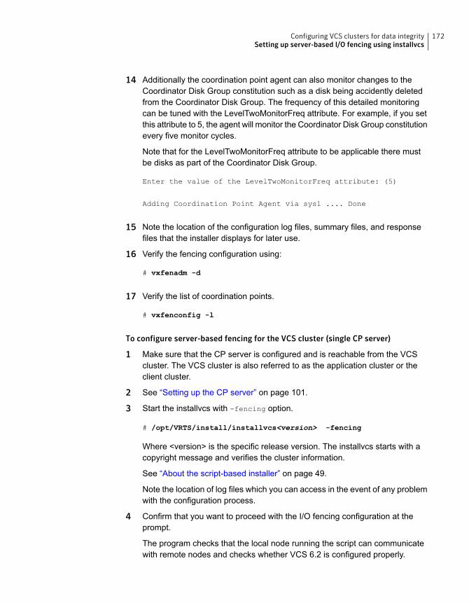
14 Additionally the coordination point agent can also monitor changes to theCoordinator Disk Group constitution such as a disk being accidently deletedfrom the Coordinator Disk Group. The frequency of this detailed monitoringcan be tuned with the LevelTwoMonitorFreq attribute. For example, if you setthis attribute to 5, the agent will monitor the Coordinator Disk Group constitutionevery five monitor cycles.
Note that for the LevelTwoMonitorFreq attribute to be applicable there mustbe disks as part of the Coordinator Disk Group.
Enter the value of the LevelTwoMonitorFreq attribute: (5)
Adding Coordination Point Agent via sys1 .... Done
15 Note the location of the configuration log files, summary files, and responsefiles that the installer displays for later use.
16 Verify the fencing configuration using:
# vxfenadm -d
17 Verify the list of coordination points.
# vxfenconfig -l
To configure server-based fencing for the VCS cluster (single CP server)
1 Make sure that the CP server is configured and is reachable from the VCScluster. The VCS cluster is also referred to as the application cluster or theclient cluster.
2 See “Setting up the CP server” on page 101.
3 Start the installvcs with -fencing option.
# /opt/VRTS/install/installvcs<version> -fencing
Where <version> is the specific release version. The installvcs starts with acopyright message and verifies the cluster information.
See “About the script-based installer” on page 49.
Note the location of log files which you can access in the event of any problemwith the configuration process.
4 Confirm that you want to proceed with the I/O fencing configuration at theprompt.
The program checks that the local node running the script can communicatewith remote nodes and checks whether VCS 6.2 is configured properly.
172Configuring VCS clusters for data integritySetting up server-based I/O fencing using installvcs
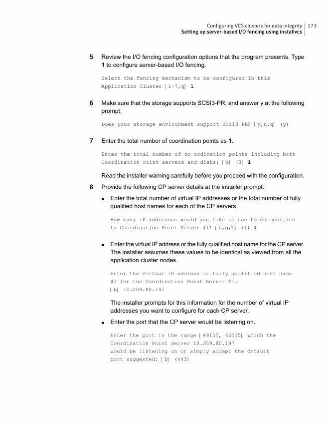
5 Review the I/O fencing configuration options that the program presents. Type1 to configure server-based I/O fencing.
Select the fencing mechanism to be configured in this
Application Cluster [1-7,q] 1
6 Make sure that the storage supports SCSI3-PR, and answer y at the followingprompt.
Does your storage environment support SCSI3 PR? [y,n,q] (y)
7 Enter the total number of coordination points as 1.
Enter the total number of co-ordination points including both
Coordination Point servers and disks: [b] (3) 1
Read the installer warning carefully before you proceed with the configuration.
8 Provide the following CP server details at the installer prompt:
■ Enter the total number of virtual IP addresses or the total number of fullyqualified host names for each of the CP servers.
How many IP addresses would you like to use to communicate
to Coordination Point Server #1? [b,q,?] (1) 1
■ Enter the virtual IP address or the fully qualified host name for the CP server.The installer assumes these values to be identical as viewed from all theapplication cluster nodes.
Enter the Virtual IP address or fully qualified host name
#1 for the Coordination Point Server #1:
[b] 10.209.80.197
The installer prompts for this information for the number of virtual IPaddresses you want to configure for each CP server.
■ Enter the port that the CP server would be listening on.
Enter the port in the range [49152, 65535] which the
Coordination Point Server 10.209.80.197
would be listening on or simply accept the default
port suggested: [b] (443)
173Configuring VCS clusters for data integritySetting up server-based I/O fencing using installvcs
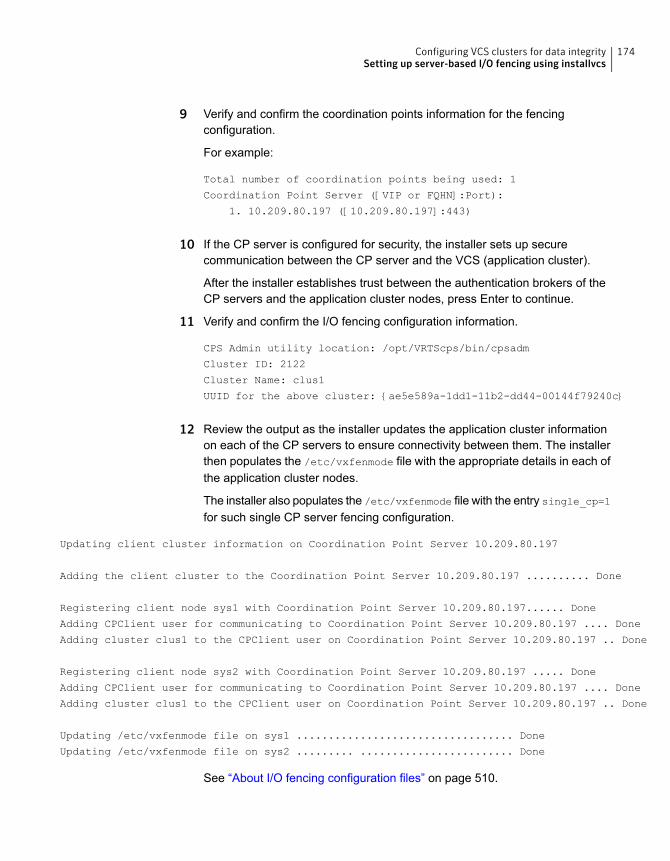
9 Verify and confirm the coordination points information for the fencingconfiguration.
For example:
Total number of coordination points being used: 1
Coordination Point Server ([VIP or FQHN]:Port):
1. 10.209.80.197 ([10.209.80.197]:443)
10 If the CP server is configured for security, the installer sets up securecommunication between the CP server and the VCS (application cluster).
After the installer establishes trust between the authentication brokers of theCP servers and the application cluster nodes, press Enter to continue.
11 Verify and confirm the I/O fencing configuration information.
CPS Admin utility location: /opt/VRTScps/bin/cpsadm
Cluster ID: 2122
Cluster Name: clus1
UUID for the above cluster: {ae5e589a-1dd1-11b2-dd44-00144f79240c}
12 Review the output as the installer updates the application cluster informationon each of the CP servers to ensure connectivity between them. The installerthen populates the /etc/vxfenmode file with the appropriate details in each ofthe application cluster nodes.
The installer also populates the /etc/vxfenmode file with the entry single_cp=1for such single CP server fencing configuration.
Updating client cluster information on Coordination Point Server 10.209.80.197
Adding the client cluster to the Coordination Point Server 10.209.80.197 .......... Done
Registering client node sys1 with Coordination Point Server 10.209.80.197...... Done
Adding CPClient user for communicating to Coordination Point Server 10.209.80.197 .... Done
Adding cluster clus1 to the CPClient user on Coordination Point Server 10.209.80.197 .. Done
Registering client node sys2 with Coordination Point Server 10.209.80.197 ..... Done
Adding CPClient user for communicating to Coordination Point Server 10.209.80.197 .... Done
Adding cluster clus1 to the CPClient user on Coordination Point Server 10.209.80.197 .. Done
Updating /etc/vxfenmode file on sys1 .................................. Done
Updating /etc/vxfenmode file on sys2 ......... ........................ Done
See “About I/O fencing configuration files” on page 510.
174Configuring VCS clusters for data integritySetting up server-based I/O fencing using installvcs
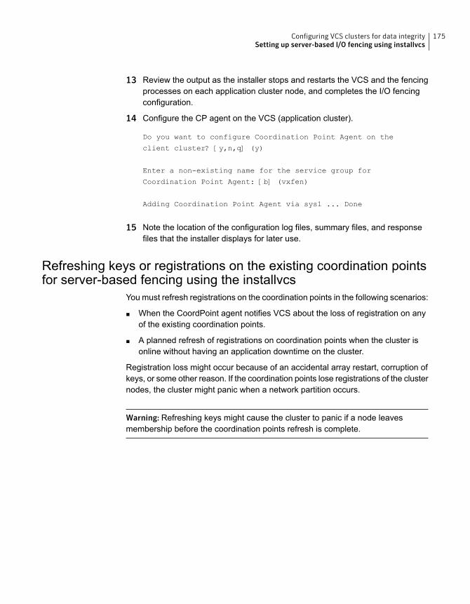
13 Review the output as the installer stops and restarts the VCS and the fencingprocesses on each application cluster node, and completes the I/O fencingconfiguration.
14 Configure the CP agent on the VCS (application cluster).
Do you want to configure Coordination Point Agent on the
client cluster? [y,n,q] (y)
Enter a non-existing name for the service group for
Coordination Point Agent: [b] (vxfen)
Adding Coordination Point Agent via sys1 ... Done
15 Note the location of the configuration log files, summary files, and responsefiles that the installer displays for later use.
Refreshing keys or registrations on the existing coordination pointsfor server-based fencing using the installvcs
You must refresh registrations on the coordination points in the following scenarios:
■ When the CoordPoint agent notifies VCS about the loss of registration on anyof the existing coordination points.
■ A planned refresh of registrations on coordination points when the cluster isonline without having an application downtime on the cluster.
Registration loss might occur because of an accidental array restart, corruption ofkeys, or some other reason. If the coordination points lose registrations of the clusternodes, the cluster might panic when a network partition occurs.
Warning: Refreshing keys might cause the cluster to panic if a node leavesmembership before the coordination points refresh is complete.
175Configuring VCS clusters for data integritySetting up server-based I/O fencing using installvcs
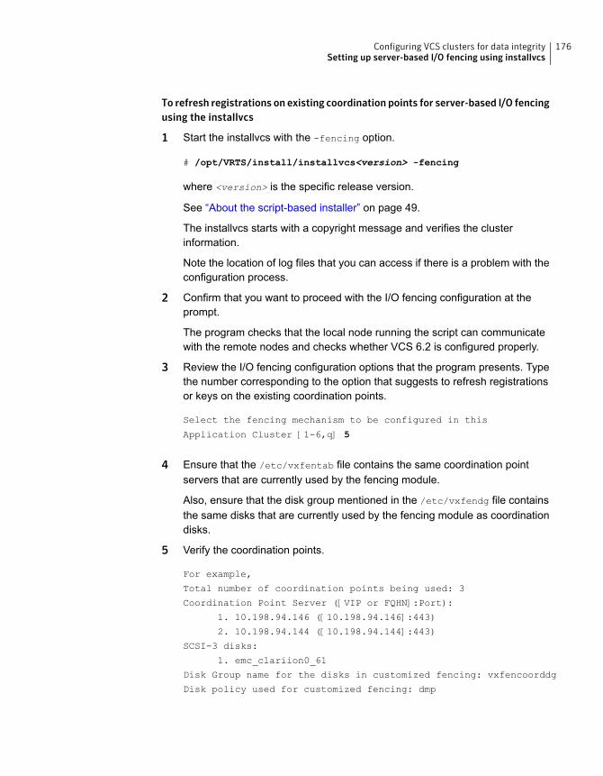
To refresh registrations on existing coordination points for server-based I/O fencingusing the installvcs
1 Start the installvcs with the -fencing option.
# /opt/VRTS/install/installvcs<version> -fencing
where <version> is the specific release version.
See “About the script-based installer” on page 49.
The installvcs starts with a copyright message and verifies the clusterinformation.
Note the location of log files that you can access if there is a problem with theconfiguration process.
2 Confirm that you want to proceed with the I/O fencing configuration at theprompt.
The program checks that the local node running the script can communicatewith the remote nodes and checks whether VCS 6.2 is configured properly.
3 Review the I/O fencing configuration options that the program presents. Typethe number corresponding to the option that suggests to refresh registrationsor keys on the existing coordination points.
Select the fencing mechanism to be configured in this
Application Cluster [1-6,q] 5
4 Ensure that the /etc/vxfentab file contains the same coordination pointservers that are currently used by the fencing module.
Also, ensure that the disk group mentioned in the /etc/vxfendg file containsthe same disks that are currently used by the fencing module as coordinationdisks.
5 Verify the coordination points.
For example,
Total number of coordination points being used: 3
Coordination Point Server ([VIP or FQHN]:Port):
1. 10.198.94.146 ([10.198.94.146]:443)
2. 10.198.94.144 ([10.198.94.144]:443)
SCSI-3 disks:
1. emc_clariion0_61
Disk Group name for the disks in customized fencing: vxfencoorddg
Disk policy used for customized fencing: dmp
176Configuring VCS clusters for data integritySetting up server-based I/O fencing using installvcs
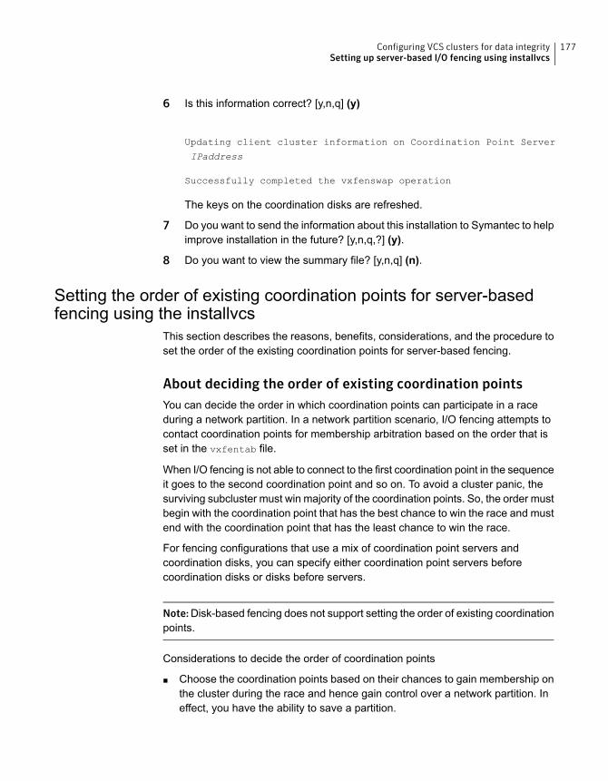
6 Is this information correct? [y,n,q] (y)
Updating client cluster information on Coordination Point Server
IPaddress
Successfully completed the vxfenswap operation
The keys on the coordination disks are refreshed.
7 Do you want to send the information about this installation to Symantec to helpimprove installation in the future? [y,n,q,?] (y).
8 Do you want to view the summary file? [y,n,q] (n).
Setting the order of existing coordination points for server-basedfencing using the installvcs
This section describes the reasons, benefits, considerations, and the procedure toset the order of the existing coordination points for server-based fencing.
About deciding the order of existing coordination pointsYou can decide the order in which coordination points can participate in a raceduring a network partition. In a network partition scenario, I/O fencing attempts tocontact coordination points for membership arbitration based on the order that isset in the vxfentab file.
When I/O fencing is not able to connect to the first coordination point in the sequenceit goes to the second coordination point and so on. To avoid a cluster panic, thesurviving subcluster must win majority of the coordination points. So, the order mustbegin with the coordination point that has the best chance to win the race and mustend with the coordination point that has the least chance to win the race.
For fencing configurations that use a mix of coordination point servers andcoordination disks, you can specify either coordination point servers beforecoordination disks or disks before servers.
Note:Disk-based fencing does not support setting the order of existing coordinationpoints.
Considerations to decide the order of coordination points
■ Choose the coordination points based on their chances to gain membership onthe cluster during the race and hence gain control over a network partition. Ineffect, you have the ability to save a partition.
177Configuring VCS clusters for data integritySetting up server-based I/O fencing using installvcs
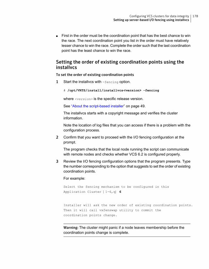
■ First in the order must be the coordination point that has the best chance to winthe race. The next coordination point you list in the order must have relativelylesser chance to win the race. Complete the order such that the last coordinationpoint has the least chance to win the race.
Setting the order of existing coordination points using theinstallvcsTo set the order of existing coordination points
1 Start the installvcs with -fencing option.
# /opt/VRTS/install/installvcs<version> -fencing
where <version> is the specific release version.
See “About the script-based installer” on page 49.
The installvcs starts with a copyright message and verifies the clusterinformation.
Note the location of log files that you can access if there is a problem with theconfiguration process.
2 Confirm that you want to proceed with the I/O fencing configuration at theprompt.
The program checks that the local node running the script can communicatewith remote nodes and checks whether VCS 6.2 is configured properly.
3 Review the I/O fencing configuration options that the program presents. Typethe number corresponding to the option that suggests to set the order of existingcoordination points.
For example:
Select the fencing mechanism to be configured in this
Application Cluster [1-6,q] 6
Installer will ask the new order of existing coordination points.
Then it will call vxfenswap utility to commit the
coordination points change.
Warning: The cluster might panic if a node leaves membership before thecoordination points change is complete.
178Configuring VCS clusters for data integritySetting up server-based I/O fencing using installvcs
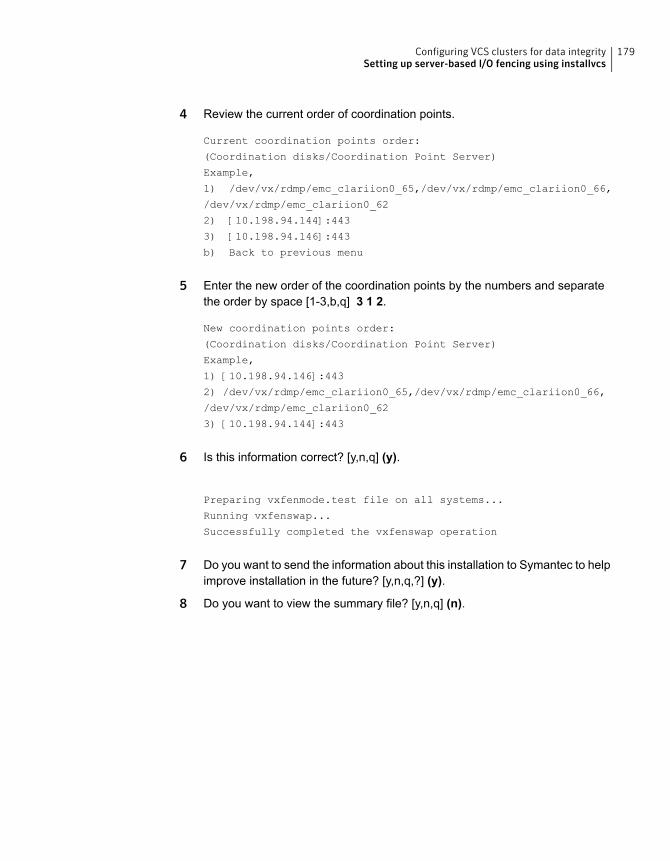
4 Review the current order of coordination points.
Current coordination points order:
(Coordination disks/Coordination Point Server)
Example,
1) /dev/vx/rdmp/emc_clariion0_65,/dev/vx/rdmp/emc_clariion0_66,
/dev/vx/rdmp/emc_clariion0_62
2) [10.198.94.144]:443
3) [10.198.94.146]:443
b) Back to previous menu
5 Enter the new order of the coordination points by the numbers and separatethe order by space [1-3,b,q] 3 1 2.
New coordination points order:
(Coordination disks/Coordination Point Server)
Example,
1) [10.198.94.146]:443
2) /dev/vx/rdmp/emc_clariion0_65,/dev/vx/rdmp/emc_clariion0_66,
/dev/vx/rdmp/emc_clariion0_62
3) [10.198.94.144]:443
6 Is this information correct? [y,n,q] (y).
Preparing vxfenmode.test file on all systems...
Running vxfenswap...
Successfully completed the vxfenswap operation
7 Do you want to send the information about this installation to Symantec to helpimprove installation in the future? [y,n,q,?] (y).
8 Do you want to view the summary file? [y,n,q] (n).
179Configuring VCS clusters for data integritySetting up server-based I/O fencing using installvcs
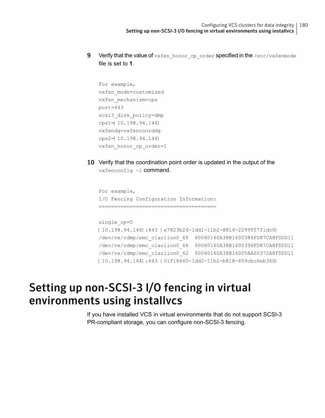
9 Verify that the value of vxfen_honor_cp_order specified in the /etc/vxfenmode
file is set to 1.
For example,
vxfen_mode=customized
vxfen_mechanism=cps
port=443
scsi3_disk_policy=dmp
cps1=[10.198.94.146]
vxfendg=vxfencoorddg
cps2=[10.198.94.144]
vxfen_honor_cp_order=1
10 Verify that the coordination point order is updated in the output of thevxfenconfig -l command.
For example,
I/O Fencing Configuration Information:
======================================
single_cp=0
[10.198.94.146]:443 {e7823b24-1dd1-11b2-8814-2299557f1dc0}
/dev/vx/rdmp/emc_clariion0_65 60060160A38B1600386FD87CA8FDDD11
/dev/vx/rdmp/emc_clariion0_66 60060160A38B1600396FD87CA8FDDD11
/dev/vx/rdmp/emc_clariion0_62 60060160A38B16005AA00372A8FDDD11
[10.198.94.144]:443 {01f18460-1dd2-11b2-b818-659cbc6eb360}
Setting up non-SCSI-3 I/O fencing in virtualenvironments using installvcs
If you have installed VCS in virtual environments that do not support SCSI-3PR-compliant storage, you can configure non-SCSI-3 fencing.
180Configuring VCS clusters for data integritySetting up non-SCSI-3 I/O fencing in virtual environments using installvcs
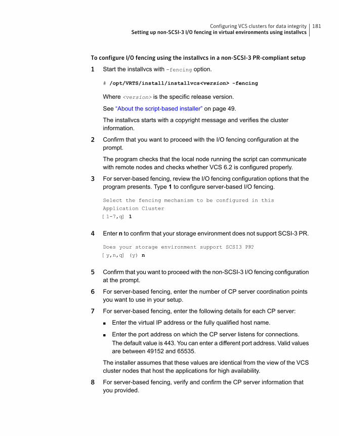
To configure I/O fencing using the installvcs in a non-SCSI-3 PR-compliant setup
1 Start the installvcs with -fencing option.
# /opt/VRTS/install/installvcs<version> -fencing
Where <version> is the specific release version.
See “About the script-based installer” on page 49.
The installvcs starts with a copyright message and verifies the clusterinformation.
2 Confirm that you want to proceed with the I/O fencing configuration at theprompt.
The program checks that the local node running the script can communicatewith remote nodes and checks whether VCS 6.2 is configured properly.
3 For server-based fencing, review the I/O fencing configuration options that theprogram presents. Type 1 to configure server-based I/O fencing.
Select the fencing mechanism to be configured in this
Application Cluster
[1-7,q] 1
4 Enter n to confirm that your storage environment does not support SCSI-3 PR.
Does your storage environment support SCSI3 PR?
[y,n,q] (y) n
5 Confirm that you want to proceed with the non-SCSI-3 I/O fencing configurationat the prompt.
6 For server-based fencing, enter the number of CP server coordination pointsyou want to use in your setup.
7 For server-based fencing, enter the following details for each CP server:
■ Enter the virtual IP address or the fully qualified host name.
■ Enter the port address on which the CP server listens for connections.The default value is 443. You can enter a different port address. Valid valuesare between 49152 and 65535.
The installer assumes that these values are identical from the view of the VCScluster nodes that host the applications for high availability.
8 For server-based fencing, verify and confirm the CP server information thatyou provided.
181Configuring VCS clusters for data integritySetting up non-SCSI-3 I/O fencing in virtual environments using installvcs
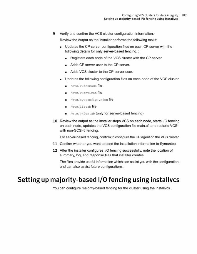
9 Verify and confirm the VCS cluster configuration information.
Review the output as the installer performs the following tasks:
■ Updates the CP server configuration files on each CP server with thefollowing details for only server-based fencing, :
■ Registers each node of the VCS cluster with the CP server.
■ Adds CP server user to the CP server.
■ Adds VCS cluster to the CP server user.
■ Updates the following configuration files on each node of the VCS cluster
■ /etc/vxfenmode file
■ /etc/vxenviron file
■ /etc/sysconfig/vxfen file
■ /etc/llttab file
■ /etc/vxfentab (only for server-based fencing)
10 Review the output as the installer stops VCS on each node, starts I/O fencingon each node, updates the VCS configuration file main.cf, and restarts VCSwith non-SCSI-3 fencing.
For server-based fencing, confirm to configure the CP agent on the VCS cluster.
11 Confirm whether you want to send the installation information to Symantec.
12 After the installer configures I/O fencing successfully, note the location ofsummary, log, and response files that installer creates.
The files provide useful information which can assist you with the configuration,and can also assist future configurations.
Setting upmajority-based I/O fencing using installvcsYou can configure majority-based fencing for the cluster using the installvcs .
182Configuring VCS clusters for data integritySetting up majority-based I/O fencing using installvcs
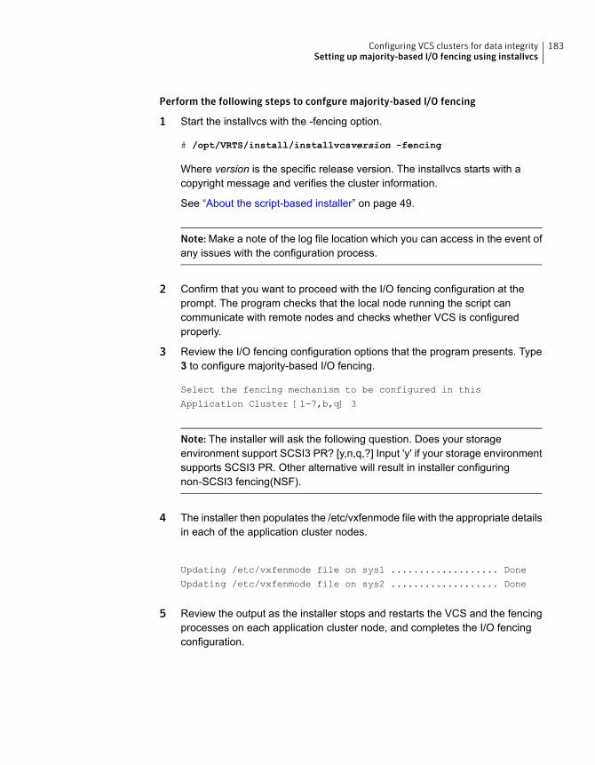
Perform the following steps to confgure majority-based I/O fencing
1 Start the installvcs with the -fencing option.
# /opt/VRTS/install/installvcsversion -fencing
Where version is the specific release version. The installvcs starts with acopyright message and verifies the cluster information.
See “About the script-based installer” on page 49.
Note: Make a note of the log file location which you can access in the event ofany issues with the configuration process.
2 Confirm that you want to proceed with the I/O fencing configuration at theprompt. The program checks that the local node running the script cancommunicate with remote nodes and checks whether VCS is configuredproperly.
3 Review the I/O fencing configuration options that the program presents. Type3 to configure majority-based I/O fencing.
Select the fencing mechanism to be configured in this
Application Cluster [1-7,b,q] 3
Note: The installer will ask the following question. Does your storageenvironment support SCSI3 PR? [y,n,q,?] Input 'y' if your storage environmentsupports SCSI3 PR. Other alternative will result in installer configuringnon-SCSI3 fencing(NSF).
4 The installer then populates the /etc/vxfenmode file with the appropriate detailsin each of the application cluster nodes.
Updating /etc/vxfenmode file on sys1 ................... Done
Updating /etc/vxfenmode file on sys2 ................... Done
5 Review the output as the installer stops and restarts the VCS and the fencingprocesses on each application cluster node, and completes the I/O fencingconfiguration.
183Configuring VCS clusters for data integritySetting up majority-based I/O fencing using installvcs
6 Note the location of the configuration log files, summary files, and responsefiles that the installer displays for later use.
7 Verify the fencing configuration.
# vxfenadm -d
Enabling or disabling the preferred fencing policyYou can enable or disable the preferred fencing feature for your I/O fencingconfiguration.
You can enable preferred fencing to use system-based race policy, group-basedrace policy, or site-based policy. If you disable preferred fencing, the I/O fencingconfiguration uses the default count-based race policy.
Preferred fencing is not applicable to majority-based I/O fencing.
See “About preferred fencing” on page 35.
To enable preferred fencing for the I/O fencing configuration
1 Make sure that the cluster is running with I/O fencing set up.
# vxfenadm -d
2 Make sure that the cluster-level attribute UseFence has the value set to SCSI3.
# haclus -value UseFence
3 To enable system-based race policy, perform the following steps:
■ Make the VCS configuration writable.
# haconf -makerw
■ Set the value of the cluster-level attribute PreferredFencingPolicy as System.
# haclus -modify PreferredFencingPolicy System
■ Set the value of the system-level attribute FencingWeight for each node inthe cluster.For example, in a two-node cluster, where you want to assign sys1 fivetimes more weight compared to sys2, run the following commands:
# hasys -modify sys1 FencingWeight 50
# hasys -modify sys2 FencingWeight 10
184Configuring VCS clusters for data integrityEnabling or disabling the preferred fencing policy
■ Save the VCS configuration.
# haconf -dump -makero
■ Verify fencing node weights using:
# vxfenconfig -a
4 To enable group-based race policy, perform the following steps:
■ Make the VCS configuration writable.
# haconf -makerw
■ Set the value of the cluster-level attribute PreferredFencingPolicy as Group.
# haclus -modify PreferredFencingPolicy Group
■ Set the value of the group-level attribute Priority for each service group.For example, run the following command:
# hagrp -modify service_group Priority 1
Make sure that you assign a parent service group an equal or lower prioritythan its child service group. In case the parent and the child service groupsare hosted in different subclusters, then the subcluster that hosts the childservice group gets higher preference.
■ Save the VCS configuration.
# haconf -dump -makero
5 To enable site-based race policy, perform the following steps:
■ Make the VCS configuration writable.
# haconf -makerw
■ Set the value of the cluster-level attribute PreferredFencingPolicy as Site.
# haclus -modify PreferredFencingPolicy Site
■ Set the value of the site-level attribute Preference for each site.
For example,
# hasite -modify Pune Preference 2
185Configuring VCS clusters for data integrityEnabling or disabling the preferred fencing policy
■ Save the VCS configuration.
# haconf -dump –makero
6 To view the fencing node weights that are currently set in the fencing driver,run the following command:
# vxfenconfig -a
To disable preferred fencing for the I/O fencing configuration
1 Make sure that the cluster is running with I/O fencing set up.
# vxfenadm -d
2 Make sure that the cluster-level attribute UseFence has the value set to SCSI3.
# haclus -value UseFence
3 To disable preferred fencing and use the default race policy, set the value ofthe cluster-level attribute PreferredFencingPolicy as Disabled.
# haconf -makerw
# haclus -modify PreferredFencingPolicy Disabled
# haconf -dump -makero
186Configuring VCS clusters for data integrityEnabling or disabling the preferred fencing policy
Installation using theWeb-based installer
■ Chapter 10. Installing VCS
■ Chapter 11. Configuring VCS
4Section
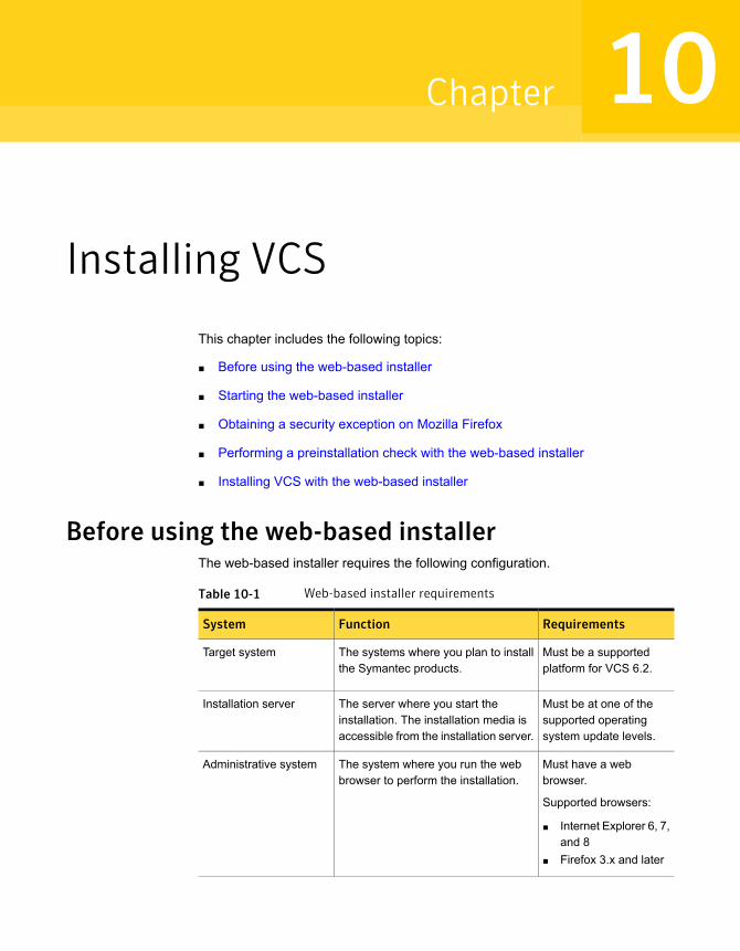
Installing VCS
This chapter includes the following topics:
■ Before using the web-based installer
■ Starting the web-based installer
■ Obtaining a security exception on Mozilla Firefox
■ Performing a preinstallation check with the web-based installer
■ Installing VCS with the web-based installer
Before using the web-based installerThe web-based installer requires the following configuration.
Table 10-1 Web-based installer requirements
RequirementsFunctionSystem
Must be a supportedplatform for VCS 6.2.
The systems where you plan to installthe Symantec products.
Target system
Must be at one of thesupported operatingsystem update levels.
The server where you start theinstallation. The installation media isaccessible from the installation server.
Installation server
Must have a webbrowser.
Supported browsers:
■ Internet Explorer 6, 7,and 8
■ Firefox 3.x and later
The system where you run the webbrowser to perform the installation.
Administrative system
10Chapter
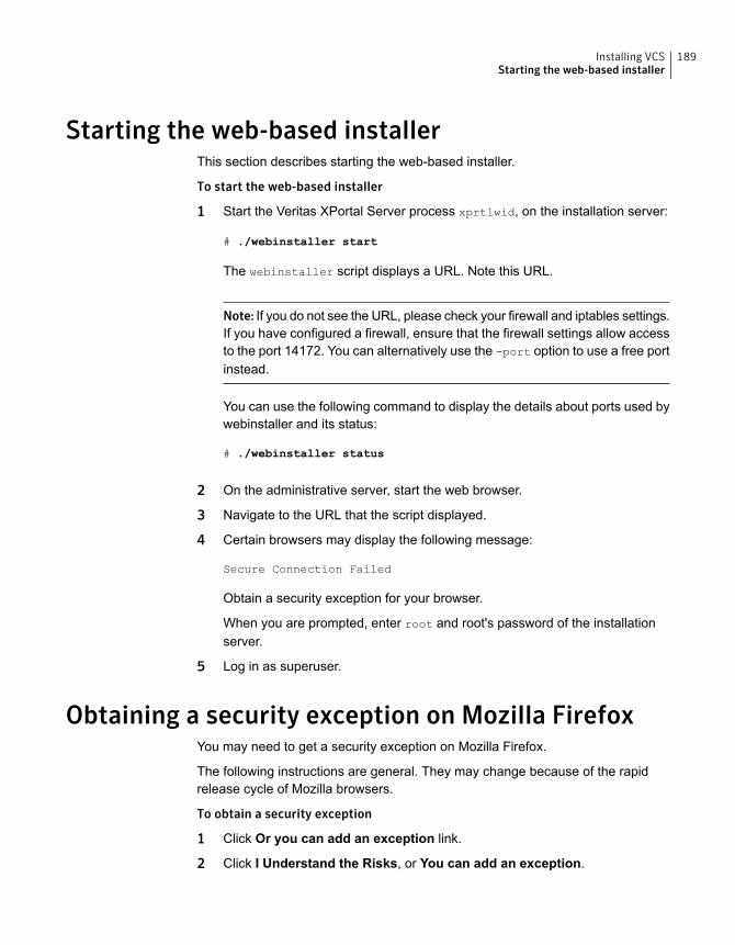
Starting the web-based installerThis section describes starting the web-based installer.
To start the web-based installer
1 Start the Veritas XPortal Server process xprtlwid, on the installation server:
# ./webinstaller start
The webinstaller script displays a URL. Note this URL.
Note: If you do not see the URL, please check your firewall and iptables settings.If you have configured a firewall, ensure that the firewall settings allow accessto the port 14172. You can alternatively use the -port option to use a free portinstead.
You can use the following command to display the details about ports used bywebinstaller and its status:
# ./webinstaller status
2 On the administrative server, start the web browser.
3 Navigate to the URL that the script displayed.
4 Certain browsers may display the following message:
Secure Connection Failed
Obtain a security exception for your browser.
When you are prompted, enter root and root's password of the installationserver.
5 Log in as superuser.
Obtaining a security exception on Mozilla FirefoxYou may need to get a security exception on Mozilla Firefox.
The following instructions are general. They may change because of the rapidrelease cycle of Mozilla browsers.
To obtain a security exception
1 Click Or you can add an exception link.
2 Click I Understand the Risks, or You can add an exception.
189Installing VCSStarting the web-based installer
3 Click Get Certificate button.
4 Uncheck Permanently Store this exception checkbox (recommended).
5 Click Confirm Security Exception button.
6 Enter root in User Name field and root password of the web server in thePassword field.
Performing a preinstallation check with theweb-based installer
This section describes performing a preinstallation check with the web-basedinstaller.
To perform a preinstallation check
1 Start the web-based installer.
See “Starting the web-based installer” on page 189.
2 On the Select a task and a product page, select Perform a Pre-installationCheck from the Task drop-down list.
3 Select Symantec Cluster Server from the Product drop-down list, and clickNext.
4 Indicate the systems on which to perform the precheck. Enter one or moresystem names, separated by spaces. Click Next.
5 The installer performs the precheck and displays the results.
6 If the validation completes successfully, click Next. The installer prompts youto begin the installation. Click Yes to install on the selected system. Click Noto install later.
7 Click Finish. The installer prompts you for another task.
Installing VCS with the web-based installerThis section describes installing VCS with the Symantec web-based installer.
190Installing VCSPerforming a preinstallation check with the web-based installer
To install VCS using the web-based installer
1 Perform preliminary steps.
See “Performing a preinstallation check with the web-based installer”on page 190.
2 Start the web-based installer.
See “Starting the web-based installer” on page 189.
3 Select Install a Product from the Task drop-down list.
4 Select Symantec Cluster Server from the Product drop-down list, and clickNext.
5 On the License agreement page, read the End User License Agreement (EULA).To continue, select Yes, I agree and click Next.
6 Choose minimal, recommended, or all RPMs. Click Next.
7 Indicate the systems where you want to install. Separate multiple system nameswith spaces. Click Next.
8 If you have not yet configured a communication mode among systems, youhave the option to let the installer configure ssh or rsh. If you choose to allowthis configuration, select the communication mode and provide the superuserpasswords for the systems.
9 After the validation completes successfully, click Next to install VCS on theselected system.
10 After the installation completes, you must choose your licensing method.
On the license page, select one of the following radio buttons:
■ Enable keyless licensing and complete system licensing later
Note: The keyless license option enables you to install without entering akey. However, to ensure compliance, you must manage the systems witha management server.
For more information, go to the following website:
http://go.symantec.com/sfhakeyless
Click Next
Complete the following information:
■ Choose whether you want to enable Global Cluster option.
■ Click Next.
191Installing VCSInstalling VCS with the web-based installer

■ Enter a valid license keyIf you have a valid license key, input the license key and click Next.
11 The installer prompts you to configure the cluster. Select Yes to continue withconfiguring the product.
If you select No, you can exit the installer. You must configure the productbefore you can use VCS.
After the installation completes, the installer displays the location of the logand summary files. If required, view the files to confirm the installation status.
12 If you are prompted, enter the option to specify whether you want to send yourinstallation information to Symantec.
Installation procedures and diagnostic information were saved in
the log files under directory
/var/tmp/installer-<platform>-<uuid>. Analyzing this information
helps Symantec discover and fix failed operations performed by
the installer. Would you like to send the information about this
installation to Symantec to help improve installation in the
future? [y,n,q,?]
Click Finish.
192Installing VCSInstalling VCS with the web-based installer
Configuring VCS
This chapter includes the following topics:
■ Configuring VCS using the web-based installer
■ Configuring VCS for data integrity using the web-based installer
Configuring VCS using the web-based installerBefore you begin to configure VCS using the web-based installer, review theconfiguration requirements.
See “Getting your VCS installation and configuration information ready” on page 79.
By default, the communication between the systems is selected as SSH. If SSH isused for communication between systems, the SSH commands execute withoutprompting for passwords or confirmations.
You can click Quit to quit the web-installer at any time during the configurationprocess.
To configure VCS on a cluster
1 Start the web-based installer.
See “Starting the web-based installer” on page 189.
2 On the Select a task and a product page, select the task and the product asfollows:
Configure a ProductTask
Symantec Cluster ServerProduct
Click Next.
11Chapter
3 On the Select Systems page, enter the system names where you want toconfigure VCS, and click Next.
Example: sys1 sys2
The installer performs the initial system verification. It checks for the systemcommunication. It also checks for release compatibility, installed productversion, platform version, and performs product prechecks.
Click Next after the installer completes the system verification successfully.
4 In the Confirmation dialog box that appears, choose whether or not to configureI/O fencing.
Would you like to configure I/O fencing on the cluster?, click Yes.
To configure I/O fencing later using the web-based installer, click No.
See “Configuring VCS for data integrity using the web-based installer”on page 199.
You can also configure I/O fencing later using the installvcs<version>
-fencing command, the response files, or manually configure.
Where <version> is the specific release version.
See “About the script-based installer” on page 49.
194Configuring VCSConfiguring VCS using the web-based installer
5 On the Set Cluster Name/ID page, specify the following information for thecluster.
Enter a unique cluster name.Cluster Name
Enter a unique cluster ID.
Note that you can have the installer check to see if the cluster IDis unique. Symantec recommends that you use the installer tocheck for duplicate cluster IDs in multi-cluster environments.
Cluster ID
Select the check box if you want the installer to verify if the givencluster ID is unique in your private network. The verification isperformed after you specify the heartbeat details in the followingpages. The verification takes some time to complete.
Check duplicatecluster ID
Select an LLT type from the list. You can choose to configure LLTover UDP or LLT over Ethernet or LLT over RDMA.
LLT Type
Choose the number of heartbeat links you want to configure.
See “Setting up the private network” on page 67.
Number ofHeartbeats
Select the check box if you want to configure a low priority link.The installer configures one heartbeat link as low priority link.
See “Setting up the private network” on page 67.
Additional LowPriority HeartbeatNIC
For LLT over Ethernet, select the check box if you do not wantto use the same NIC details to configure private heartbeat linkson other systems.
For LLT over UDP, this check box is selected by default.
For LLT over RDMA, this check box is selected by default.
Unique HeartbeatNICs per system
Click Next.
6 On the Set Cluster Heartbeat page, select the heartbeat link details for the LLTtype you chose on the Set Cluster Name/ID page.
Do the following:
■ If you are using the same NICs on all the systems, selectthe NIC for each private heartbeat link.
■ If you had selected Unique Heartbeat NICs per systemon the Set Cluster Name/ID page, provide the NIC detailsfor each system.
For LLT over Ethernet:
195Configuring VCSConfiguring VCS using the web-based installer
Select the NIC, Port, and IP address for each privateheartbeat link. You must provide these details for eachsystem.
For LLT over UDP:
Select the NIC, Port, and IP address for each privateheartbeat link. You must provide these details for eachsystem.
For LLT over RDMA
Click Next.
7 On the Optional Configuration page, decide the optional VCS features that youwant to configure. Click the corresponding tab to specify the details for eachoption:
To configure a secure VCS cluster, select the Configuresecure cluster check box.
If you want to perform this task later, do not select theConfigure secure cluster check box. You can use the-security option of the installvcs<version>.
Security
■ Select the Configure Virtual IP check box.■ If each system uses a separate NIC, select the
Configure NICs for every system separately checkbox.
■ Select the interface on which you want to configure thevirtual IP.
■ Enter a virtual IP address and value for the netmask.You can use an IPv4 or an IPv6 address.
Virtual IP
■ Reset the password for the Admin user, if necessary.■ Select the Configure VCS users option.■ Click Add to add a new user.
Specify the user name, password, and user privilegesfor this user.
VCS Users
196Configuring VCSConfiguring VCS using the web-based installer
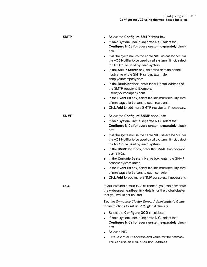
■ Select the Configure SMTP check box.■ If each system uses a separate NIC, select the
Configure NICs for every system separately checkbox.
■ If all the systems use the same NIC, select the NIC forthe VCS Notifier to be used on all systems. If not, selectthe NIC to be used by each system.
■ In the SMTP Server box, enter the domain-basedhostname of the SMTP server. Example:smtp.yourcompany.com
■ In the Recipient box, enter the full email address ofthe SMTP recipient. Example:[email protected].
■ In the Event list box, select the minimum security levelof messages to be sent to each recipient.
■ Click Add to add more SMTP recipients, if necessary.
SMTP
■ Select the Configure SNMP check box.■ If each system uses a separate NIC, select the
Configure NICs for every system separately checkbox.
■ If all the systems use the same NIC, select the NIC forthe VCS Notifier to be used on all systems. If not, selectthe NIC to be used by each system.
■ In the SNMP Port box, enter the SNMP trap daemonport: (162).
■ In the Console System Name box, enter the SNMPconsole system name.
■ In the Event list box, select the minimum security levelof messages to be sent to each console.
■ Click Add to add more SNMP consoles, if necessary.
SNMP
If you installed a valid HA/DR license, you can now enterthe wide-area heartbeat link details for the global clusterthat you would set up later.
See the Symantec Cluster Server Administrator's Guidefor instructions to set up VCS global clusters.
■ Select the Configure GCO check box.■ If each system uses a separate NIC, select the
Configure NICs for every system separately checkbox.
■ Select a NIC.■ Enter a virtual IP address and value for the netmask.
You can use an IPv4 or an IPv6 address.
GCO
197Configuring VCSConfiguring VCS using the web-based installer
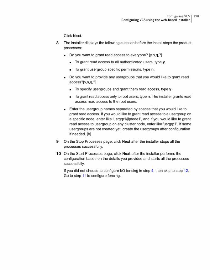
Click Next.
8 The installer displays the following question before the install stops the productprocesses:
■ Do you want to grant read access to everyone? [y,n,q,?]
■ To grant read access to all authenticated users, type y.
■ To grant usergroup specific permissions, type n.
■ Do you want to provide any usergroups that you would like to grant readaccess?[y,n,q,?]
■ To specify usergroups and grant them read access, type y
■ To grant read access only to root users, type n. The installer grants readaccess read access to the root users.
■ Enter the usergroup names separated by spaces that you would like togrant read access. If you would like to grant read access to a usergroup ona specific node, enter like 'usrgrp1@node1', and if you would like to grantread access to usergroup on any cluster node, enter like 'usrgrp1'. If someusergroups are not created yet, create the usergroups after configurationif needed. [b]
9 On the Stop Processes page, click Next after the installer stops all theprocesses successfully.
10 On the Start Processes page, click Next after the installer performs theconfiguration based on the details you provided and starts all the processessuccessfully.
If you did not choose to configure I/O fencing in step 4, then skip to step 12.Go to step 11 to configure fencing.
198Configuring VCSConfiguring VCS using the web-based installer
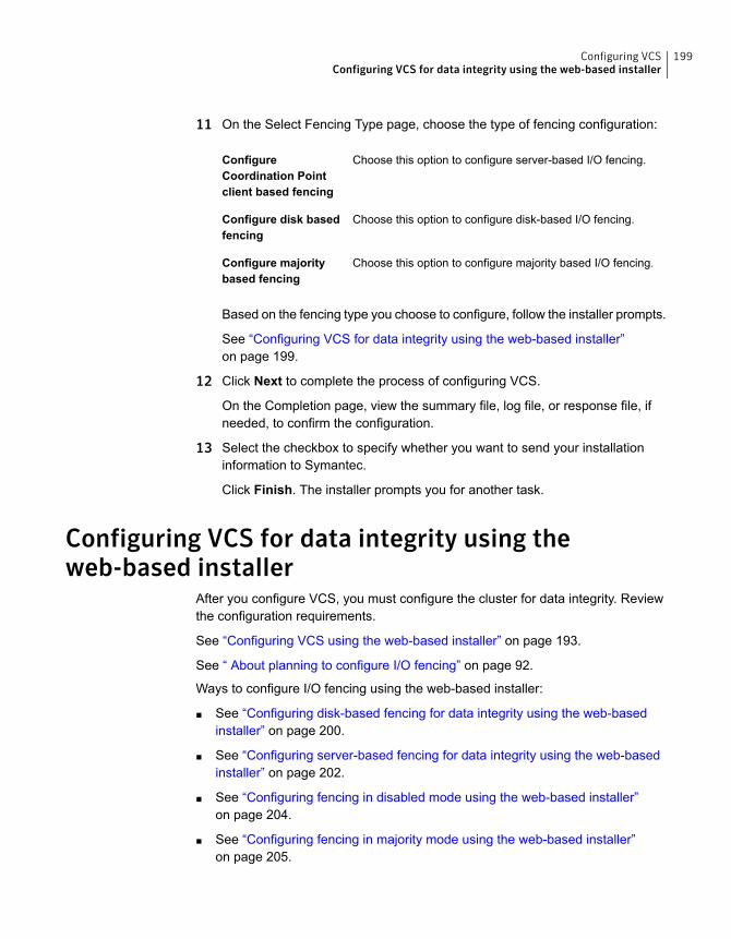
11 On the Select Fencing Type page, choose the type of fencing configuration:
Choose this option to configure server-based I/O fencing.ConfigureCoordination Pointclient based fencing
Choose this option to configure disk-based I/O fencing.Configure disk basedfencing
Choose this option to configure majority based I/O fencing.Configure majoritybased fencing
Based on the fencing type you choose to configure, follow the installer prompts.
See “Configuring VCS for data integrity using the web-based installer”on page 199.
12 Click Next to complete the process of configuring VCS.
On the Completion page, view the summary file, log file, or response file, ifneeded, to confirm the configuration.
13 Select the checkbox to specify whether you want to send your installationinformation to Symantec.
Click Finish. The installer prompts you for another task.
Configuring VCS for data integrity using theweb-based installer
After you configure VCS, you must configure the cluster for data integrity. Reviewthe configuration requirements.
See “Configuring VCS using the web-based installer” on page 193.
See “ About planning to configure I/O fencing” on page 92.
Ways to configure I/O fencing using the web-based installer:
■ See “Configuring disk-based fencing for data integrity using the web-basedinstaller” on page 200.
■ See “Configuring server-based fencing for data integrity using the web-basedinstaller” on page 202.
■ See “Configuring fencing in disabled mode using the web-based installer”on page 204.
■ See “Configuring fencing in majority mode using the web-based installer”on page 205.
199Configuring VCSConfiguring VCS for data integrity using the web-based installer
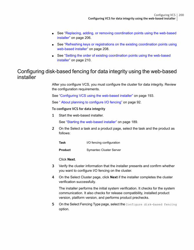
■ See “Replacing, adding, or removing coordination points using the web-basedinstaller” on page 206.
■ See “Refreshing keys or registrations on the existing coordination points usingweb-based installer” on page 208.
■ See “Setting the order of existing coordination points using the web-basedinstaller” on page 210.
Configuring disk-based fencing for data integrity using the web-basedinstaller
After you configure VCS, you must configure the cluster for data integrity. Reviewthe configuration requirements.
See “Configuring VCS using the web-based installer” on page 193.
See “ About planning to configure I/O fencing” on page 92.
To configure VCS for data integrity
1 Start the web-based installer.
See “Starting the web-based installer” on page 189.
2 On the Select a task and a product page, select the task and the product asfollows:
I/O fencing configurationTask
Symantec Cluster ServerProduct
Click Next.
3 Verify the cluster information that the installer presents and confirm whetheryou want to configure I/O fencing on the cluster.
4 On the Select Cluster page, click Next if the installer completes the clusterverification successfully.
The installer performs the initial system verification. It checks for the systemcommunication. It also checks for release compatibility, installed productversion, platform version, and performs product prechecks.
5 On the Select Fencing Type page, select the Configure disk-based fencing
option.
200Configuring VCSConfiguring VCS for data integrity using the web-based installer
6 In the Confirmation dialog box that appears, confirm whether your storageenvironment supports SCSI-3 PR.
You can configure non-SCSI-3 fencing in a virtual environment that is notSCSI-3 PR compliant.
7 On the Configure Fencing page, the installer prompts for details based on thefencing type you chose to configure. Specify the coordination points details.
Click Next.
8 On the Configure Fencing page, specify the following information:
Select the Create a new disk group option or select one ofthe disk groups from the list.
■ If you selected one of the disk groups that is listed, choosethe fencing disk policy for the disk group.
■ If you selected theCreate a new disk group option, makesure you have SCSI-3 PR enabled disks, and click Yesin the confirmation dialog box.Click Next.
Select a Disk Group
9 On the Create New DG page, specify the following information:
Enter a name for the new coordinator disk group you wantto create.
NewDisk Group Name
Select at least three disks to create the coordinator diskgroup.
If you want to select more than three disks, make sure toselect an odd number of disks.
Select Disks
10 Verify and confirm the I/O fencing configuration information.
The installer stops and restarts the VCS and the fencing processes on eachapplication cluster node, and completes the I/O fencing configuration.
11 If you want to configure the Coordination Point agent on the client cluster, dothe following:
■ At the prompt for configuring the Coordination Point agent on the clientcluster, click Yes and enter the Coordination Point agent service groupname.
■ If you want to set the LevelTwoMonitorFreq attribute, click Yes at the promptand enter a value (0 to 65535).
201Configuring VCSConfiguring VCS for data integrity using the web-based installer
■ Follow the rest of the prompts to complete the Coordination Point agentconfiguration.
12 Click Next to complete the process of configuring I/O fencing.
On the Completion page, view the summary file, log file, or response file, ifneeded, to confirm the configuration.
13 Select the checkbox to specify whether you want to send your installationinformation to Symantec.
Click Finish. The installer prompts you for another task.
Configuring server-based fencing for data integrity using theweb-based installer
After you configure VCS, you must configure the cluster for data integrity. Reviewthe configuration requirements.
See “Configuring VCS using the web-based installer” on page 193.
See “ About planning to configure I/O fencing” on page 92.
To configure VCS for data integrity
1 Start the web-based installer.
See “Starting the web-based installer” on page 189.
2 On the Select a task and a product page, select the task and the product asfollows:
I/O fencing configurationTask
Symantec Cluster ServerProduct
Click Next.
3 Verify the cluster information that the installer presents and confirm whetheryou want to configure I/O fencing on the cluster.
4 On the Select Cluster page, click Next if the installer completes the clusterverification successfully.
The installer performs the initial system verification. It checks for the systemcommunication. It also checks for release compatibility, installed productversion, platform version, and performs product prechecks.
5 On the Select Fencing Type page, select the Configure Coordination Point
client based fencing option.
202Configuring VCSConfiguring VCS for data integrity using the web-based installer
6 In the Confirmation dialog box that appears, confirm whether your storageenvironment supports SCSI-3 PR.
You can configure non-SCSI-3 fencing in a virtual environment that is notSCSI-3 PR compliant.
7 On the Configure Fencing page, the installer prompts for details based on thefencing type you chose to configure. Specify the coordination points details.
Click Next.
8 Provide the following details for each of the CP servers:
■ Enter the virtual IP addresses or host names of the virtual IP address. Theinstaller assumes these values to be identical as viewed from all theapplication cluster nodes.
■ Enter the port that the CP server must listen on.
■ Click Next.
9 If your server-based fencing configuration also uses disks as coordinationpoints, perform the following steps:
■ If you have not already checked the disks for SCSI-3 PR compliance, checkthe disks now, and click OK in the dialog box.
■ If you do not want to use the default coordinator disk group name, enter aname for the new coordinator disk group you want to create.
■ Select the disks to create the coordinator disk group.
■ Choose the fencing disk policy for the disk group.The default fencing disk policy for the disk group is dmp.
10 In the Confirmation dialog box that appears, confirm whether the coordinationpoints information you provided is correct, and click Yes.
11 Verify and confirm the I/O fencing configuration information.
The installer stops and restarts the VCS and the fencing processes on eachapplication cluster node, and completes the I/O fencing configuration.
12 If you want to configure the Coordination Point agent on the client cluster, dothe following:
■ At the prompt for configuring the Coordination Point agent on the clientcluster, click Yes and enter the Coordination Point agent service groupname.
■ Follow the rest of the prompts to complete the Coordination Point agentconfiguration.
203Configuring VCSConfiguring VCS for data integrity using the web-based installer
13 Click Next to complete the process of configuring I/O fencing.
On the Completion page, view the summary file, log file, or response file, ifneeded, to confirm the configuration.
14 Select the checkbox to specify whether you want to send your installationinformation to Symantec.
Click Finish. The installer prompts you for another task.
Configuring fencing in disabled mode using the web-based installerAfter you configure VCS, you must configure the cluster for data integrity. Reviewthe configuration requirements.
See “Configuring VCS using the web-based installer” on page 193.
See “ About planning to configure I/O fencing” on page 92.
To configure VCS for data integrity
1 Start the web-based installer.
See “Starting the web-based installer” on page 189.
2 On the Select a task and a product page, select the task and the product asfollows:
I/O fencing configurationTask
Symantec Cluster ServerProduct
Click Next.
3 Verify the cluster information that the installer presents and confirm whetheryou want to configure I/O fencing on the cluster.
4 On the Select Cluster page, click Next if the installer completes the clusterverification successfully.
The installer performs the initial system verification. It checks for the systemcommunication. It also checks for release compatibility, installed productversion, platform version, and performs product prechecks.
5 Fencing may be enabled, installer may prompt whether you want to reconfigureit.
Click Yes.
6 On the Select Fencing Type page, select the Configure fencing in disabled
mode option.
204Configuring VCSConfiguring VCS for data integrity using the web-based installer
7 Installer stops VCS before applying the selected fencing mode to the cluster.
Note: Unfreeze any frozen service group and unmount any file system that ismounted in the cluster.
Click Yes.
8 Installer restarts VCS on all systems of the cluster. I/O fencing is disabled.
9 Verify and confirm the I/O fencing configuration information.
On the Completion page, view the summary file, log file, or response file, ifneeded, to confirm the configuration.
10 Select the checkbox to specify whether you want to send your installationinformation to Symantec.
Click Finish. The installer prompts you for another task.
Configuring fencing in majority mode using the web-based installerAfter you configure VCS, you must configure the cluster for data integrity. Reviewthe configuration requirements.
See “Configuring VCS using the web-based installer” on page 193.
See “ About planning to configure I/O fencing” on page 92.
To configure VCS for data integrity
1 Start the web-based installer.
See “Starting the web-based installer” on page 189.
2 On the Select a task and a product page, select the task and the product asfollows:
I/O fencing configurationTask
Symantec Cluster ServerProduct
Click Next.
3 Verify the cluster information that the installer presents and confirm whetheryou want to configure I/O fencing on the cluster.
205Configuring VCSConfiguring VCS for data integrity using the web-based installer
4 On the Select Cluster page, click Next if the installer completes the clusterverification successfully.
The installer performs the initial system verification. It checks for the systemcommunication. It also checks for release compatibility, installed productversion, platform version, and performs product prechecks.
5 Fencing may be enabled, installer may prompt whether you want to reconfigureit.
Click Yes.
6 On the Select Fencing Type page, select the Configure fencing in majority
mode option.
7 Installer stops VCS before applying the selected fencing mode to the cluster.
Note: Unfreeze any frozen service group and unmount any file system that ismounted in the cluster.
Click Yes.
8 Installer restarts VCS on all systems of the cluster. I/O fencing is in majoritymode.
9 Verify and confirm the I/O fencing configuration information.
On the Completion page, view the summary file, log file, or response file, ifneeded, to confirm the configuration.
10 Select the checkbox to specify whether you want to send your installationinformation to Symantec.
Click Finish. The installer prompts you for another task.
Replacing, adding, or removing coordination points using theweb-based installer
After you configure VCS, you must configure the cluster for data integrity. Reviewthe configuration requirements.
This procedure does not apply to majority-based I/O fencing.
See “Configuring VCS using the web-based installer” on page 193.
See “ About planning to configure I/O fencing” on page 92.
206Configuring VCSConfiguring VCS for data integrity using the web-based installer
To configure VCS for data integrity
1 Start the web-based installer.
See “Starting the web-based installer” on page 189.
2 On the Select a task and a product page, select the task and the product asfollows:
I/O Fencing configurationTask
Symantec Cluster ServerProduct
Click Next.
3 Verify the cluster information that the installer presents and confirm whetheryou want to configure I/O Fencing on the cluster.
4 On the Select Cluster page, click Next if the installer completes the clusterverification successfully.
The installer performs the initial system verification. It checks for the systemcommunication. It also checks for release compatibility, installed productversion, platform version, and performs product prechecks.
5 Fencing may be enabled, installer may prompt whether you want to reconfigureit.
Click Yes.
6 On the Select Fencing Type page, select the Replace/Add/Remove
coordination points option.
7 The installer prompts to select the coordination points you want to remove fromthe currently configured coordination points.
Click Next.
8 Provide the number of Coordination point server and disk coordination pointsto be added to the configuration.
Click Next.
9 Provide the number of virtual IP addresses or Fully Qualified Host Name(FQHN) used for each coordination point server.
Click Next.
10 Provide the IP or FQHN and port number for each coordination point server.
Click Next.
207Configuring VCSConfiguring VCS for data integrity using the web-based installer
11 Installer prompts to confirm the online migration coordination point servers.
Click Yes.
12 Installer proceeds with migration of the new coordination point servers. VCSis restarted during configuration.
Click Next.
13 You can add a Coordination Point agent to the client cluster and also providename to the agent.
14 Click Next.
15 On the Completion page, view the summary file, log file, or response file, ifneeded, to confirm the configuration.
16 Select the check box to specify whether you want to send your installationinformation to Symantec.
Click Finish. The installer prompts you for another task.
Refreshing keys or registrations on the existing coordination pointsusing web-based installer
This procedure does not apply to majority-based I/O fencing.
You must refresh registrations on the coordination points in the following scenarios:
■ When the CoordPoint agent notifies VCS about the loss of registration on anyof the existing coordination points.
■ A planned refresh of registrations on coordination points when the cluster isonline without having an application downtime on the cluster.
Registration loss may happen because of an accidental array restart, corruption ofkeys, or some other reason. If the coordination points lose the registrations of thecluster nodes, the cluster may panic when a network partition occurs.
Warning: Refreshing keys might cause the cluster to panic if a node leavesmembership before the coordination points refresh is complete.
208Configuring VCSConfiguring VCS for data integrity using the web-based installer
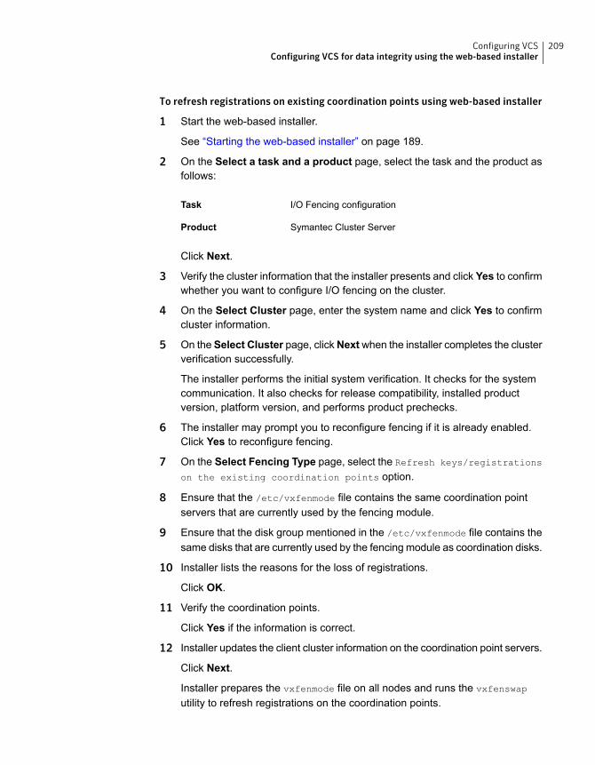
To refresh registrations on existing coordination points using web-based installer
1 Start the web-based installer.
See “Starting the web-based installer” on page 189.
2 On the Select a task and a product page, select the task and the product asfollows:
I/O Fencing configurationTask
Symantec Cluster ServerProduct
Click Next.
3 Verify the cluster information that the installer presents and click Yes to confirmwhether you want to configure I/O fencing on the cluster.
4 On the Select Cluster page, enter the system name and click Yes to confirmcluster information.
5 On the Select Cluster page, clickNextwhen the installer completes the clusterverification successfully.
The installer performs the initial system verification. It checks for the systemcommunication. It also checks for release compatibility, installed productversion, platform version, and performs product prechecks.
6 The installer may prompt you to reconfigure fencing if it is already enabled.Click Yes to reconfigure fencing.
7 On the Select Fencing Type page, select the Refresh keys/registrations
on the existing coordination points option.
8 Ensure that the /etc/vxfenmode file contains the same coordination pointservers that are currently used by the fencing module.
9 Ensure that the disk group mentioned in the /etc/vxfenmode file contains thesame disks that are currently used by the fencing module as coordination disks.
10 Installer lists the reasons for the loss of registrations.
Click OK.
11 Verify the coordination points.
Click Yes if the information is correct.
12 Installer updates the client cluster information on the coordination point servers.
Click Next.
Installer prepares the vxfenmode file on all nodes and runs the vxfenswap
utility to refresh registrations on the coordination points.
209Configuring VCSConfiguring VCS for data integrity using the web-based installer
13 On the Completion page, view the summary file, log file, or response file toconfirm the configuration.
14 Select the check box to specify whether you want to send your installationinformation to Symantec.
Click Finish.
Setting the order of existing coordination points using the web-basedinstaller
This section describes the reasons, benefits, considerations, and the procedure toset the order of the existing coordination points using the web-based installer.
It does not apply to majority-based I/O fencing.
About deciding the order of existing coordination pointsYou can decide the order in which coordination points can participate in a raceduring a network partition. In a network partition scenario, I/O fencing attempts tocontact coordination points for membership arbitration based on the order that isset in the vxfenmode file.
When I/O fencing is not able to connect to the first coordination point in the sequenceit goes to the second coordination point and so on. To avoid a cluster panic, thesurviving subcluster must win majority of the coordination points. So, the order mustbegin with the coordination point that has the best chance to win the race and mustend with the coordination point that has the least chance to win the race
For fencing configurations that use a mix of coordination point servers andcoordination disks, you can either specify coordination point servers beforecoordination point disks or disks before servers.
Note:Disk-based fencing does not support setting the order of existing coordinationpoints.
Considerations to decide the order of coordination points
■ Choose coordination points based on their chances gain membership on thecluster during the race and hence gain control over a network partition. In effect,you have the ability to save a partition.
■ First in the order must be the coordination point that has the best chance to winthe race. The next coordination point you list in the order must have relativelylesser chance to win the race. Complete the order such that the last coordinationpoint has the least chance to win the race.
210Configuring VCSConfiguring VCS for data integrity using the web-based installer
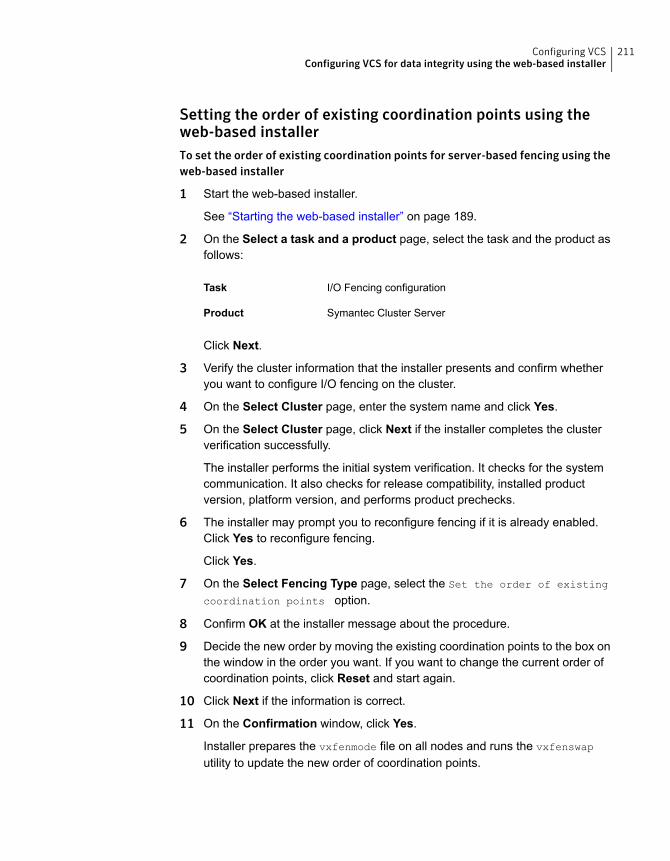
Setting the order of existing coordination points using theweb-based installerTo set the order of existing coordination points for server-based fencing using theweb-based installer
1 Start the web-based installer.
See “Starting the web-based installer” on page 189.
2 On the Select a task and a product page, select the task and the product asfollows:
I/O Fencing configurationTask
Symantec Cluster ServerProduct
Click Next.
3 Verify the cluster information that the installer presents and confirm whetheryou want to configure I/O fencing on the cluster.
4 On the Select Cluster page, enter the system name and click Yes.
5 On the Select Cluster page, click Next if the installer completes the clusterverification successfully.
The installer performs the initial system verification. It checks for the systemcommunication. It also checks for release compatibility, installed productversion, platform version, and performs product prechecks.
6 The installer may prompt you to reconfigure fencing if it is already enabled.Click Yes to reconfigure fencing.
Click Yes.
7 On the Select Fencing Type page, select the Set the order of existing
coordination points option.
8 Confirm OK at the installer message about the procedure.
9 Decide the new order by moving the existing coordination points to the box onthe window in the order you want. If you want to change the current order ofcoordination points, click Reset and start again.
10 Click Next if the information is correct.
11 On the Confirmation window, click Yes.
Installer prepares the vxfenmode file on all nodes and runs the vxfenswap
utility to update the new order of coordination points.
211Configuring VCSConfiguring VCS for data integrity using the web-based installer
12 On the Completion page, view the summary file, log file, or response file toconfirm the configuration.
13 Select the check box to specify whether you want to send your installationinformation to Symantec.
Click Finish.
212Configuring VCSConfiguring VCS for data integrity using the web-based installer
Automated installation usingresponse files
■ Chapter 12. Performing an automated VCS installation
■ Chapter 13. Performing an automated VCS configuration
■ Chapter 14. Performing an automated I/O fencing configuration using responsefiles
5Section
Performing an automatedVCS installation
This chapter includes the following topics:
■ Installing VCS using response files
■ Response file variables to install VCS
■ Sample response file for installing VCS
Installing VCS using response filesTypically, you can use the response file that the installer generates after you performVCS installation on one cluster to install VCS on other clusters. You can also createa response file using the -makeresponsefile option of the installer.
# ./installer -makeresponsefile
See “About the script-based installer” on page 49.
To install VCS using response files
1 Make sure the systems where you want to install VCS meet the installationrequirements.
2 Make sure that the preinstallation tasks are completed.
See “Performing preinstallation tasks” on page 66.
3 Copy the response file to one of the cluster systems where you want to installVCS.
See “Sample response file for installing VCS” on page 218.
12Chapter
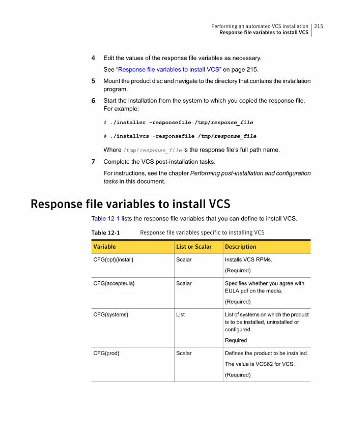
4 Edit the values of the response file variables as necessary.
See “Response file variables to install VCS” on page 215.
5 Mount the product disc and navigate to the directory that contains the installationprogram.
6 Start the installation from the system to which you copied the response file.For example:
# ./installer -responsefile /tmp/response_file
# ./installvcs -responsefile /tmp/response_file
Where /tmp/response_file is the response file’s full path name.
7 Complete the VCS post-installation tasks.
For instructions, see the chapter Performing post-installation and configurationtasks in this document.
Response file variables to install VCSTable 12-1 lists the response file variables that you can define to install VCS.
Table 12-1 Response file variables specific to installing VCS
DescriptionList or ScalarVariable
Installs VCS RPMs.
(Required)
ScalarCFG{opt}{install}
Specifies whether you agree withEULA.pdf on the media.
(Required)
ScalarCFG{accepteula}
List of systems on which the productis to be installed, uninstalled orconfigured.
Required
ListCFG{systems}
Defines the product to be installed.
The value is VCS62 for VCS.
(Required)
ScalarCFG{prod}
215Performing an automated VCS installationResponse file variables to install VCS
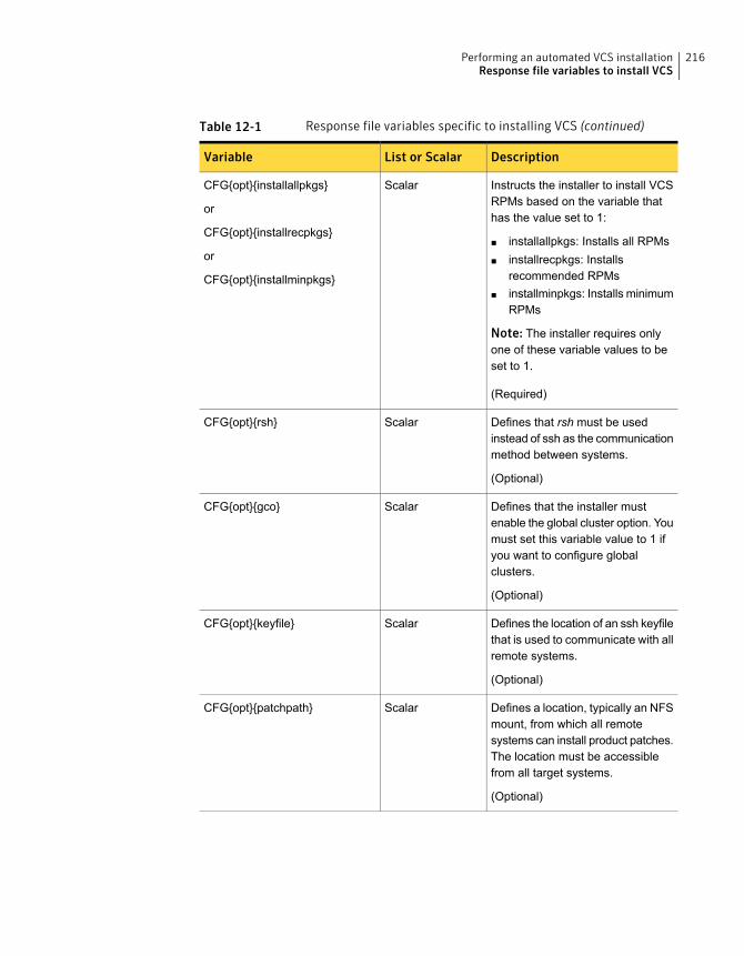
Table 12-1 Response file variables specific to installing VCS (continued)
DescriptionList or ScalarVariable
Instructs the installer to install VCSRPMs based on the variable thathas the value set to 1:
■ installallpkgs: Installs all RPMs■ installrecpkgs: Installs
recommended RPMs■ installminpkgs: Installs minimum
RPMs
Note: The installer requires onlyone of these variable values to beset to 1.
(Required)
ScalarCFG{opt}{installallpkgs}
or
CFG{opt}{installrecpkgs}
or
CFG{opt}{installminpkgs}
Defines that rsh must be usedinstead of ssh as the communicationmethod between systems.
(Optional)
ScalarCFG{opt}{rsh}
Defines that the installer mustenable the global cluster option. Youmust set this variable value to 1 ifyou want to configure globalclusters.
(Optional)
ScalarCFG{opt}{gco}
Defines the location of an ssh keyfilethat is used to communicate with allremote systems.
(Optional)
ScalarCFG{opt}{keyfile}
Defines a location, typically an NFSmount, from which all remotesystems can install product patches.The location must be accessiblefrom all target systems.
(Optional)
ScalarCFG{opt}{patchpath}
216Performing an automated VCS installationResponse file variables to install VCS
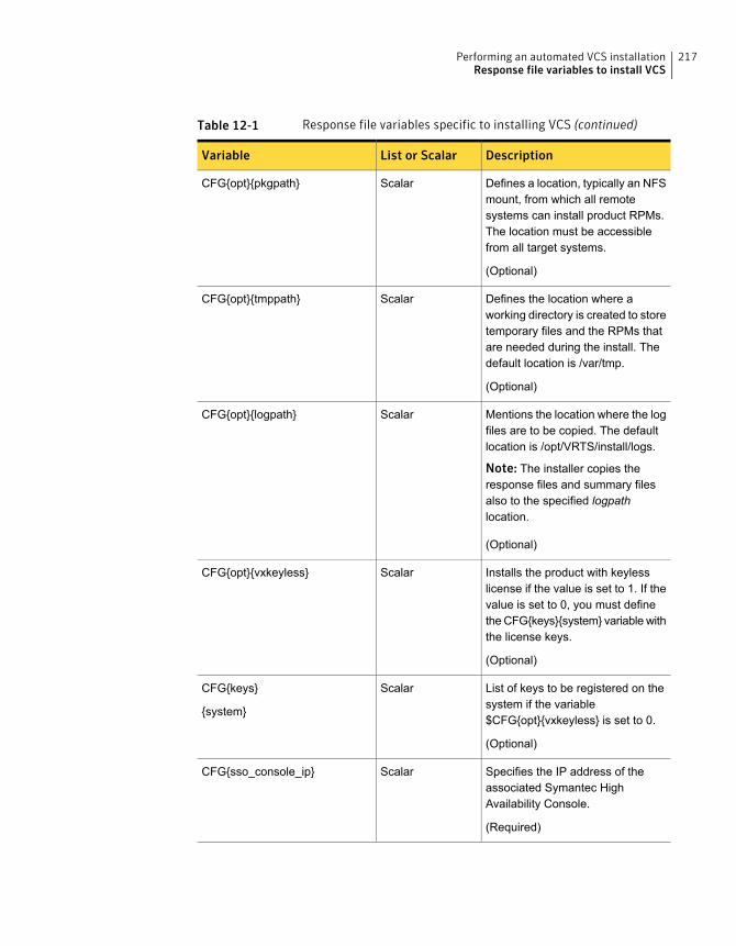
Table 12-1 Response file variables specific to installing VCS (continued)
DescriptionList or ScalarVariable
Defines a location, typically an NFSmount, from which all remotesystems can install product RPMs.The location must be accessiblefrom all target systems.
(Optional)
ScalarCFG{opt}{pkgpath}
Defines the location where aworking directory is created to storetemporary files and the RPMs thatare needed during the install. Thedefault location is /var/tmp.
(Optional)
ScalarCFG{opt}{tmppath}
Mentions the location where the logfiles are to be copied. The defaultlocation is /opt/VRTS/install/logs.
Note: The installer copies theresponse files and summary filesalso to the specified logpathlocation.
(Optional)
ScalarCFG{opt}{logpath}
Installs the product with keylesslicense if the value is set to 1. If thevalue is set to 0, you must definethe CFG{keys}{system} variable withthe license keys.
(Optional)
ScalarCFG{opt}{vxkeyless}
List of keys to be registered on thesystem if the variable$CFG{opt}{vxkeyless} is set to 0.
(Optional)
ScalarCFG{keys}
{system}
Specifies the IP address of theassociated Symantec HighAvailability Console.
(Required)
ScalarCFG{sso_console_ip}
217Performing an automated VCS installationResponse file variables to install VCS
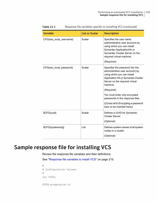
Table 12-1 Response file variables specific to installing VCS (continued)
DescriptionList or ScalarVariable
Specifies the user name(administrative user account) byusing which you can installSymantec ApplicationHA orSymantec Cluster Server on therequired virtual machine.
(Required)
ScalarCFG{sso_local_username}
Specifies the password (for theadministrative user account) byusing which you can installApplication HA or Symantec ClusterServer on the required virtualmachine.
(Required)
You must enter only encryptedpasswords in the response files.
((Cross ref to Encrypting a passwordtopic to be inserted here))
ScalarCFG{sso_local_password}
Defines a UUID for SymantecCluster Server.
(Optional)
Scalar$CFG{uuid}
Defines system names of all systemnodes in a cluster.
(Optional)
List$CFG{systemscfg}
Sample response file for installing VCSReview the response file variables and their definitions.
See “Response file variables to install VCS” on page 215.
#
# Configuration Values:
#
our %CFG;
$CFG{accepteula}=1;
218Performing an automated VCS installationSample response file for installing VCS

$CFG{opt}{install}=1;
$CFG{opt}{installrecpkgs}=1;
$CFG{prod}="VCS62";
$CFG{systems}=[ qw(sys1 sys2) ];
$CFG{uuid} = "16889f4e-1dd2-11b2-a559-afce02598e1b";
1;
219Performing an automated VCS installationSample response file for installing VCS
Performing an automatedVCS configuration
This chapter includes the following topics:
■ Configuring VCS using response files
■ Response file variables to configure Symantec Cluster Server
■ Sample response file for configuring Symantec Cluster Server
Configuring VCS using response filesTypically, you can use the response file that the installer generates after you performVCS configuration on one cluster to configure VCS on other clusters. You can alsocreate a response file using the -makeresponsefile option of the installer.
# ./installer -makeresponsefile -configure
# ./installvcs -makeresponsefile -configure
To configure VCS using response files
1 Make sure the VCS RPMs are installed on the systems where you want toconfigure VCS.
2 Copy the response file to one of the cluster systems where you want toconfigure VCS.
See “Sample response file for configuring Symantec Cluster Server” on page 232.
13Chapter

3 Edit the values of the response file variables as necessary.
To configure optional features, you must define appropriate values for all theresponse file variables that are related to the optional feature.
See “Response file variables to configure Symantec Cluster Server” on page 221.
4 Start the configuration from the system to which you copied the response file.For example:
# /opt/VRTS/install/installvcs<version>
-responsefile /tmp/response_file
Where <version> is the specific release version, and /tmp/response_file
is the response file’s full path name.
See “About the script-based installer” on page 49.
Response file variables to configureSymantecClusterServer
Table 13-1 lists the response file variables that you can define to configure VCS.
Table 13-1 Response file variables specific to configuring Symantec ClusterServer
DescriptionList or ScalarVariable
Performs the configuration if theRPMs are already installed.
(Required)
Set the value to 1 to configure VCS.
ScalarCFG{opt}{configure}
Specifies whether you agree withEULA.pdf on the media.
(Required)
ScalarCFG{accepteula}
List of systems on which the productis to be configured.
(Required)
ListCFG{systems}
Defines the product to beconfigured.
The value is VCS62 for VCS.
(Required)
ScalarCFG{prod}
221Performing an automated VCS configurationResponse file variables to configure Symantec Cluster Server

Table 13-1 Response file variables specific to configuring Symantec ClusterServer (continued)
DescriptionList or ScalarVariable
Defines the location of an ssh keyfilethat is used to communicate with allremote systems.
(Optional)
ScalarCFG{opt}{keyfile}
Defines the user groups which getread access to the cluster.
(Optional)
ListCFG{secusrgrps}
Defines the read access to thecluster only for root and other usersor usergroups which are grantedexplicit privileges on VCS objects.
(Optional)
ScalarCFG {rootsecusrgrps}
Defines that rsh must be usedinstead of ssh as the communicationmethod between systems.
(Optional)
ScalarCFG{opt}{rsh}
Mentions the location where the logfiles are to be copied. The defaultlocation is /opt/VRTS/install/logs.
Note: The installer copies theresponse files and summary filesalso to the specified logpathlocation.
(Optional)
ScalarCFG{opt}{logpath}
Defines a Boolean value 0 or 1.
The value 1 indicates that theinstallation logs are uploaded to theSymantec website.
The value 0 indicates that theinstallation logs are not uploaded tothe Symantec website.
(Optional)
ScalarCFG{uploadlogs}
222Performing an automated VCS configurationResponse file variables to configure Symantec Cluster Server
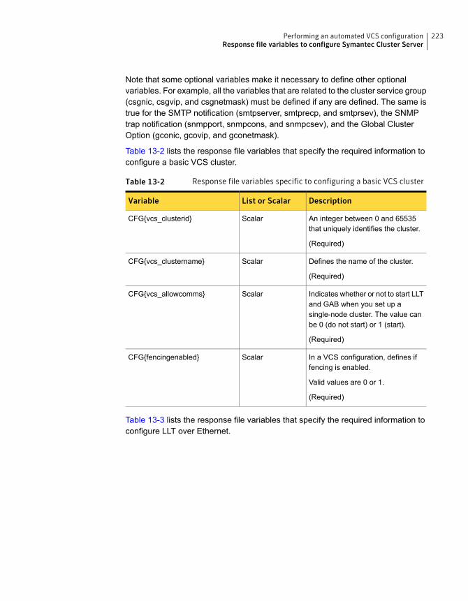
Note that some optional variables make it necessary to define other optionalvariables. For example, all the variables that are related to the cluster service group(csgnic, csgvip, and csgnetmask) must be defined if any are defined. The same istrue for the SMTP notification (smtpserver, smtprecp, and smtprsev), the SNMPtrap notification (snmpport, snmpcons, and snmpcsev), and the Global ClusterOption (gconic, gcovip, and gconetmask).
Table 13-2 lists the response file variables that specify the required information toconfigure a basic VCS cluster.
Table 13-2 Response file variables specific to configuring a basic VCS cluster
DescriptionList or ScalarVariable
An integer between 0 and 65535that uniquely identifies the cluster.
(Required)
ScalarCFG{vcs_clusterid}
Defines the name of the cluster.
(Required)
ScalarCFG{vcs_clustername}
Indicates whether or not to start LLTand GAB when you set up asingle-node cluster. The value canbe 0 (do not start) or 1 (start).
(Required)
ScalarCFG{vcs_allowcomms}
In a VCS configuration, defines iffencing is enabled.
Valid values are 0 or 1.
(Required)
ScalarCFG{fencingenabled}
Table 13-3 lists the response file variables that specify the required information toconfigure LLT over Ethernet.
223Performing an automated VCS configurationResponse file variables to configure Symantec Cluster Server
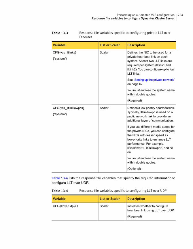
Table 13-3 Response file variables specific to configuring private LLT overEthernet
DescriptionList or ScalarVariable
Defines the NIC to be used for aprivate heartbeat link on eachsystem. Atleast two LLT links arerequired per system (lltlink1 andlltlink2). You can configure up to fourLLT links.
See “Setting up the private network”on page 67.
You must enclose the system namewithin double quotes.
(Required)
ScalarCFG{vcs_lltlink#}
{"system"}
Defines a low priority heartbeat link.Typically, lltlinklowpri is used on apublic network link to provide anadditional layer of communication.
If you use different media speed forthe private NICs, you can configurethe NICs with lesser speed aslow-priority links to enhance LLTperformance. For example,lltlinklowpri1, lltlinklowpri2, and soon.
You must enclose the system namewithin double quotes.
(Optional)
ScalarCFG{vcs_lltlinklowpri#}
{"system"}
Table 13-4 lists the response file variables that specify the required information toconfigure LLT over UDP.
Table 13-4 Response file variables specific to configuring LLT over UDP
DescriptionList or ScalarVariable
Indicates whether to configureheartbeat link using LLT over UDP.
(Required)
ScalarCFG{lltoverudp}=1
224Performing an automated VCS configurationResponse file variables to configure Symantec Cluster Server
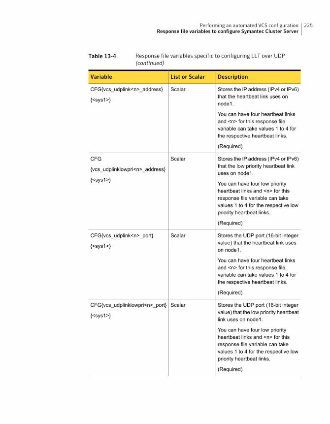
Table 13-4 Response file variables specific to configuring LLT over UDP(continued)
DescriptionList or ScalarVariable
Stores the IP address (IPv4 or IPv6)that the heartbeat link uses onnode1.
You can have four heartbeat linksand <n> for this response filevariable can take values 1 to 4 forthe respective heartbeat links.
(Required)
ScalarCFG{vcs_udplink<n>_address}
{<sys1>}
Stores the IP address (IPv4 or IPv6)that the low priority heartbeat linkuses on node1.
You can have four low priorityheartbeat links and <n> for thisresponse file variable can takevalues 1 to 4 for the respective lowpriority heartbeat links.
(Required)
ScalarCFG
{vcs_udplinklowpri<n>_address}
{<sys1>}
Stores the UDP port (16-bit integervalue) that the heartbeat link useson node1.
You can have four heartbeat linksand <n> for this response filevariable can take values 1 to 4 forthe respective heartbeat links.
(Required)
ScalarCFG{vcs_udplink<n>_port}
{<sys1>}
Stores the UDP port (16-bit integervalue) that the low priority heartbeatlink uses on node1.
You can have four low priorityheartbeat links and <n> for thisresponse file variable can takevalues 1 to 4 for the respective lowpriority heartbeat links.
(Required)
ScalarCFG{vcs_udplinklowpri<n>_port}
{<sys1>}
225Performing an automated VCS configurationResponse file variables to configure Symantec Cluster Server

Table 13-4 Response file variables specific to configuring LLT over UDP(continued)
DescriptionList or ScalarVariable
Stores the netmask (prefix for IPv6)that the heartbeat link uses onnode1.
You can have four heartbeat linksand <n> for this response filevariable can take values 1 to 4 forthe respective heartbeat links.
(Required)
ScalarCFG{vcs_udplink<n>_netmask}
{<sys1>}
Stores the netmask (prefix for IPv6)that the low priority heartbeat linkuses on node1.
You can have four low priorityheartbeat links and <n> for thisresponse file variable can takevalues 1 to 4 for the respective lowpriority heartbeat links.
(Required)
ScalarCFG{vcs_udplinklowpri<n>_netmask}
{<sys1>}
Table 13-5 lists the response file variables that specify the required information toconfigure LLT over RDMA.
Table 13-5 Response file variables specific to configuring LLT over RDMA
DescriptionList or ScalarVariable
Indicates whether to configureheartbeat link using LLT overRDMA.
(Required)
ScalarCFG{lltoverrdma}=1
Stores the IP address (IPv4 or IPv6)that the heartbeat link uses onnode1.
You can have four heartbeat linksand <n> for this response filevariable can take values 1 to 4 forthe respective heartbeat links.
(Required)
ScalarCFG{vcs_rdmalink<n>_address}
{<sys1>}
226Performing an automated VCS configurationResponse file variables to configure Symantec Cluster Server
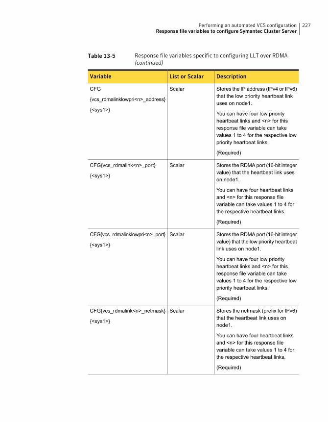
Table 13-5 Response file variables specific to configuring LLT over RDMA(continued)
DescriptionList or ScalarVariable
Stores the IP address (IPv4 or IPv6)that the low priority heartbeat linkuses on node1.
You can have four low priorityheartbeat links and <n> for thisresponse file variable can takevalues 1 to 4 for the respective lowpriority heartbeat links.
(Required)
ScalarCFG
{vcs_rdmalinklowpri<n>_address}
{<sys1>}
Stores the RDMA port (16-bit integervalue) that the heartbeat link useson node1.
You can have four heartbeat linksand <n> for this response filevariable can take values 1 to 4 forthe respective heartbeat links.
(Required)
ScalarCFG{vcs_rdmalink<n>_port}
{<sys1>}
Stores the RDMA port (16-bit integervalue) that the low priority heartbeatlink uses on node1.
You can have four low priorityheartbeat links and <n> for thisresponse file variable can takevalues 1 to 4 for the respective lowpriority heartbeat links.
(Required)
ScalarCFG{vcs_rdmalinklowpri<n>_port}
{<sys1>}
Stores the netmask (prefix for IPv6)that the heartbeat link uses onnode1.
You can have four heartbeat linksand <n> for this response filevariable can take values 1 to 4 forthe respective heartbeat links.
(Required)
ScalarCFG{vcs_rdmalink<n>_netmask}
{<sys1>}
227Performing an automated VCS configurationResponse file variables to configure Symantec Cluster Server

Table 13-5 Response file variables specific to configuring LLT over RDMA(continued)
DescriptionList or ScalarVariable
Stores the netmask (prefix for IPv6)that the low priority heartbeat linkuses on node1.
You can have four low priorityheartbeat links and <n> for thisresponse file variable can takevalues 1 to 4 for the respective lowpriority heartbeat links.
(Required)
ScalarCFG{vcs_rdmalinklowpri<n>_netmask}
{<sys1>}
Table 13-6 lists the response file variables that specify the required information toconfigure virtual IP for VCS cluster.
Table 13-6 Response file variables specific to configuring virtual IP for VCScluster
DescriptionList or ScalarVariable
Defines the NIC device to use on asystem. You can enter ‘all’ as asystem value if the same NIC isused on all systems.
(Optional)
ScalarCFG{vcs_csgnic}
{system}
Defines the virtual IP address forthe cluster.
(Optional)
ScalarCFG{vcs_csgvip}
Defines the Netmask of the virtualIP address for the cluster.
(Optional)
ScalarCFG{vcs_csgnetmask}
Table 13-7 lists the response file variables that specify the required information toconfigure the VCS cluster in secure mode.
228Performing an automated VCS configurationResponse file variables to configure Symantec Cluster Server
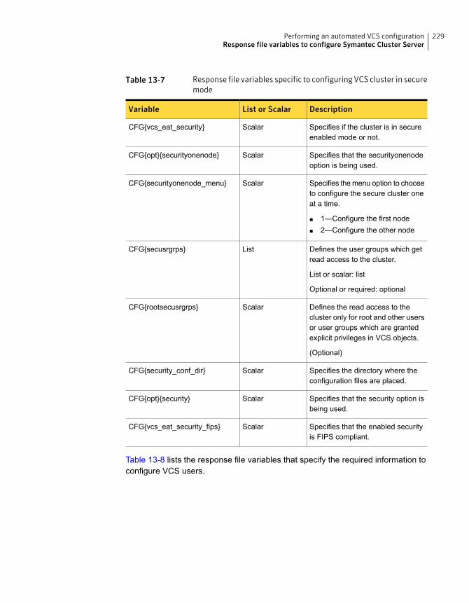
Table 13-7 Response file variables specific to configuring VCS cluster in securemode
DescriptionList or ScalarVariable
Specifies if the cluster is in secureenabled mode or not.
ScalarCFG{vcs_eat_security}
Specifies that the securityonenodeoption is being used.
ScalarCFG{opt}{securityonenode}
Specifies the menu option to chooseto configure the secure cluster oneat a time.
■ 1—Configure the first node■ 2—Configure the other node
ScalarCFG{securityonenode_menu}
Defines the user groups which getread access to the cluster.
List or scalar: list
Optional or required: optional
ListCFG{secusrgrps}
Defines the read access to thecluster only for root and other usersor user groups which are grantedexplicit privileges in VCS objects.
(Optional)
ScalarCFG{rootsecusrgrps}
Specifies the directory where theconfiguration files are placed.
ScalarCFG{security_conf_dir}
Specifies that the security option isbeing used.
ScalarCFG{opt}{security}
Specifies that the enabled securityis FIPS compliant.
ScalarCFG{vcs_eat_security_fips}
Table 13-8 lists the response file variables that specify the required information toconfigure VCS users.
229Performing an automated VCS configurationResponse file variables to configure Symantec Cluster Server
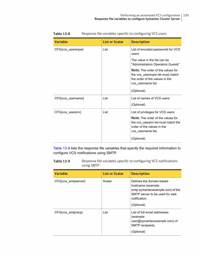
Table 13-8 Response file variables specific to configuring VCS users
DescriptionList or ScalarVariable
List of encoded passwords for VCSusers
The value in the list can be"Administrators Operators Guests"
Note: The order of the values forthe vcs_userenpw list must matchthe order of the values in thevcs_username list.
(Optional)
ListCFG{vcs_userenpw}
List of names of VCS users
(Optional)
ListCFG{vcs_username}
List of privileges for VCS users
Note: The order of the values forthe vcs_userpriv list must match theorder of the values in thevcs_username list.
(Optional)
ListCFG{vcs_userpriv}
Table 13-9 lists the response file variables that specify the required information toconfigure VCS notifications using SMTP.
Table 13-9 Response file variables specific to configuring VCS notificationsusing SMTP
DescriptionList or ScalarVariable
Defines the domain-basedhostname (example:smtp.symantecexample.com) of theSMTP server to be used for webnotification.
(Optional)
ScalarCFG{vcs_smtpserver}
List of full email addresses(example:[email protected]) ofSMTP recipients.
(Optional)
ListCFG{vcs_smtprecp}
230Performing an automated VCS configurationResponse file variables to configure Symantec Cluster Server
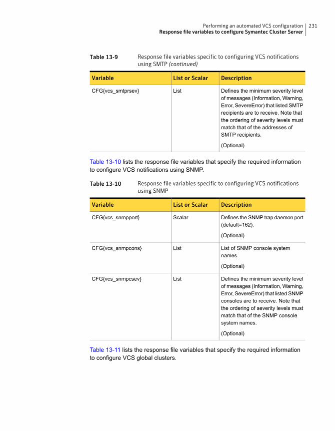
Table 13-9 Response file variables specific to configuring VCS notificationsusing SMTP (continued)
DescriptionList or ScalarVariable
Defines the minimum severity levelof messages (Information, Warning,Error, SevereError) that listed SMTPrecipients are to receive. Note thatthe ordering of severity levels mustmatch that of the addresses ofSMTP recipients.
(Optional)
ListCFG{vcs_smtprsev}
Table 13-10 lists the response file variables that specify the required informationto configure VCS notifications using SNMP.
Table 13-10 Response file variables specific to configuring VCS notificationsusing SNMP
DescriptionList or ScalarVariable
Defines the SNMP trap daemon port(default=162).
(Optional)
ScalarCFG{vcs_snmpport}
List of SNMP console systemnames
(Optional)
ListCFG{vcs_snmpcons}
Defines the minimum severity levelof messages (Information, Warning,Error, SevereError) that listed SNMPconsoles are to receive. Note thatthe ordering of severity levels mustmatch that of the SNMP consolesystem names.
(Optional)
ListCFG{vcs_snmpcsev}
Table 13-11 lists the response file variables that specify the required informationto configure VCS global clusters.
231Performing an automated VCS configurationResponse file variables to configure Symantec Cluster Server
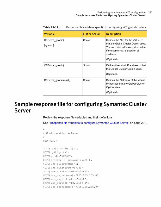
Table 13-11 Response file variables specific to configuring VCS global clusters
DescriptionList or ScalarVariable
Defines the NIC for the Virtual IPthat the Global Cluster Option uses.You can enter ‘all’ as a system valueif the same NIC is used on allsystems.
(Optional)
ScalarCFG{vcs_gconic}
{system}
Defines the virtual IP address to thatthe Global Cluster Option uses.
(Optional)
ScalarCFG{vcs_gcovip}
Defines the Netmask of the virtualIP address that the Global ClusterOption uses.
(Optional)
ScalarCFG{vcs_gconetmask}
Sample response file for configuringSymantecClusterServer
Review the response file variables and their definitions.
See “Response file variables to configure Symantec Cluster Server” on page 221.
#
# Configuration Values:
#
our %CFG;
$CFG{opt}{configure}=1;
$CFG{opt}{gco}=1;
$CFG{prod}="VCS62";
$CFG{systems}=[ qw(sys1 sys2) ];
$CFG{vcs_allowcomms}=1;
$CFG{vcs_clusterid}=13221;
$CFG{vcs_clustername}="clus1";
$CFG{vcs_csgnetmask}="255.255.255.0";
$CFG{vcs_csgnic}{all}="eth0";
$CFG{vcs_csgvip}="10.10.12.1";
$CFG{vcs_gconetmask}="255.255.255.0";
232Performing an automated VCS configurationSample response file for configuring Symantec Cluster Server
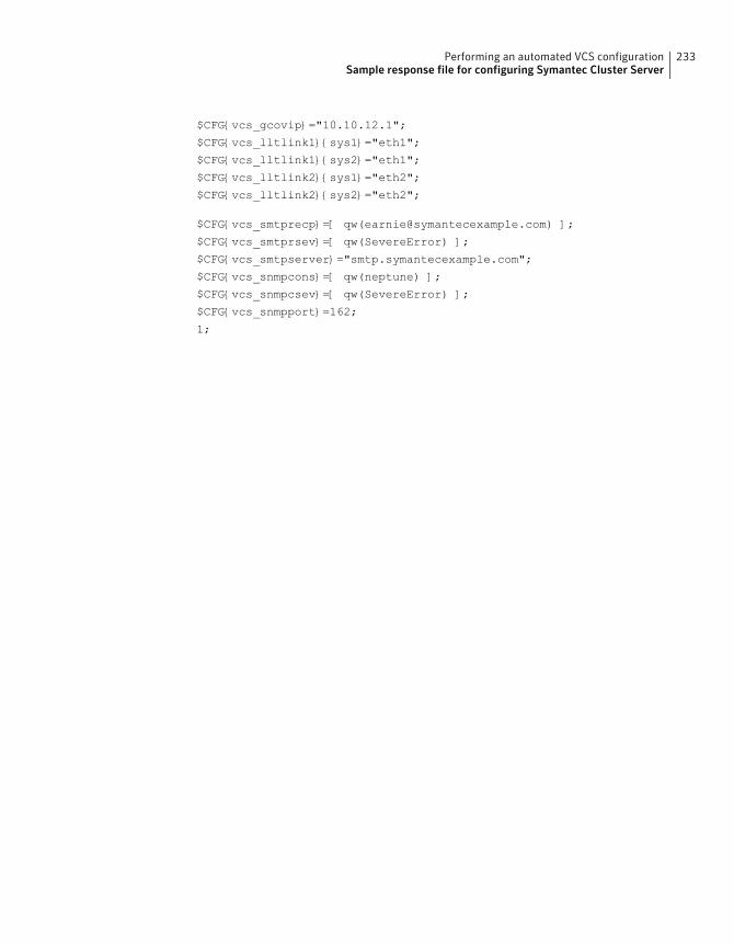
$CFG{vcs_gcovip}="10.10.12.1";
$CFG{vcs_lltlink1}{sys1}="eth1";
$CFG{vcs_lltlink1}{sys2}="eth1";
$CFG{vcs_lltlink2}{sys1}="eth2";
$CFG{vcs_lltlink2}{sys2}="eth2";
$CFG{vcs_smtprecp}=[ qw([email protected]) ];
$CFG{vcs_smtprsev}=[ qw(SevereError) ];
$CFG{vcs_smtpserver}="smtp.symantecexample.com";
$CFG{vcs_snmpcons}=[ qw(neptune) ];
$CFG{vcs_snmpcsev}=[ qw(SevereError) ];
$CFG{vcs_snmpport}=162;
1;
233Performing an automated VCS configurationSample response file for configuring Symantec Cluster Server
Performing an automatedI/O fencing configurationusing response files
This chapter includes the following topics:
■ Configuring I/O fencing using response files
■ Response file variables to configure disk-based I/O fencing
■ Sample response file for configuring disk-based I/O fencing
■ Response file variables to configure server-based I/O fencing
■ Sample response file for configuring server-based I/O fencing
■ Response file variables to configure non-SCSI-3 I/O fencing
■ Sample response file for configuring non-SCSI-3 I/O fencing
■ Response file variables to configure majority-based I/O fencing
■ Sample response file for configuring majority-based I/O fencing
Configuring I/O fencing using response filesTypically, you can use the response file that the installer generates after you performI/O fencing configuration to configure I/O fencing for VCS.
14Chapter
To configure I/O fencing using response files
1 Make sure that VCS is configured.
2 Based on whether you want to configure disk-based or server-based I/O fencing,make sure you have completed the preparatory tasks.
See “ About planning to configure I/O fencing” on page 92.
3 Copy the response file to one of the cluster systems where you want toconfigure I/O fencing.
See “Sample response file for configuring disk-based I/O fencing” on page 238.
See “Sample response file for configuring server-based I/O fencing” on page 240.
See “Sample response file for configuring non-SCSI-3 I/O fencing” on page 242.
See “Sample response file for configuring majority-based I/O fencing”on page 243.
4 Edit the values of the response file variables as necessary.
See “Response file variables to configure disk-based I/O fencing” on page 235.
See “Response file variables to configure server-based I/O fencing” on page 238.
See “Response file variables to configure non-SCSI-3 I/O fencing” on page 241.
See “Response file variables to configure majority-based I/O fencing”on page 243.
5 Start the configuration from the system to which you copied the response file.For example:
# /opt/VRTS/install/installvcs<version>
-responsefile /tmp/response_file
Where <version> is the specific release version, and /tmp/response_file
is the response file’s full path name.
See “About the script-based installer” on page 49.
Response file variables to configure disk-based I/Ofencing
Table 14-1 lists the response file variables that specify the required information toconfigure disk-based I/O fencing for VCS.
235Performing an automated I/O fencing configuration using response filesResponse file variables to configure disk-based I/O fencing
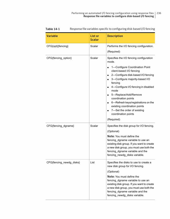
Table 14-1 Response file variables specific to configuring disk-based I/O fencing
DescriptionList orScalar
Variable
Performs the I/O fencing configuration.
(Required)
ScalarCFG{opt}{fencing}
Specifies the I/O fencing configurationmode.
■ 1—Configure Coordination Pointclient-based I/O fencing
■ 2—Configure disk-based I/O fencing■ 3—Configure majority-based I/O
fencing■ 4—Configure I/O fencing in disabled
mode■ 5—Replace/Add/Remove
coordination points■ 6—Refresh keys/registrations on the
existing coordination points■ 7—Set the order of existing
coordination points
(Required)
ScalarCFG{fencing_option}
Specifies the disk group for I/O fencing.
(Optional)
Note: You must define thefencing_dgname variable to use anexisting disk group. If you want to createa new disk group, you must use both thefencing_dgname variable and thefencing_newdg_disks variable.
ScalarCFG{fencing_dgname}
Specifies the disks to use to create anew disk group for I/O fencing.
(Optional)
Note: You must define thefencing_dgname variable to use anexisting disk group. If you want to createa new disk group, you must use both thefencing_dgname variable and thefencing_newdg_disks variable.
ListCFG{fencing_newdg_disks}
236Performing an automated I/O fencing configuration using response filesResponse file variables to configure disk-based I/O fencing
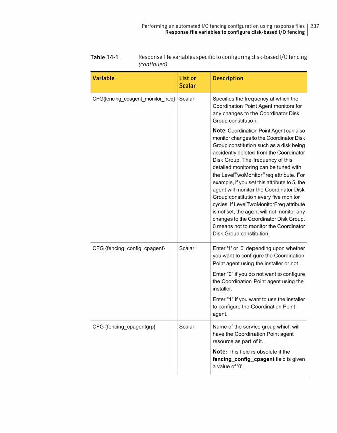
Table 14-1 Response file variables specific to configuring disk-based I/O fencing(continued)
DescriptionList orScalar
Variable
Specifies the frequency at which theCoordination Point Agent monitors forany changes to the Coordinator DiskGroup constitution.
Note:Coordination Point Agent can alsomonitor changes to the Coordinator DiskGroup constitution such as a disk beingaccidently deleted from the CoordinatorDisk Group. The frequency of thisdetailed monitoring can be tuned withthe LevelTwoMonitorFreq attribute. Forexample, if you set this attribute to 5, theagent will monitor the Coordinator DiskGroup constitution every five monitorcycles. If LevelTwoMonitorFreq attributeis not set, the agent will not monitor anychanges to the Coordinator Disk Group.0 means not to monitor the CoordinatorDisk Group constitution.
ScalarCFG{fencing_cpagent_monitor_freq}
Enter '1' or '0' depending upon whetheryou want to configure the CoordinationPoint agent using the installer or not.
Enter "0" if you do not want to configurethe Coordination Point agent using theinstaller.
Enter "1" if you want to use the installerto configure the Coordination Pointagent.
ScalarCFG {fencing_config_cpagent}
Name of the service group which willhave the Coordination Point agentresource as part of it.
Note: This field is obsolete if thefencing_config_cpagent field is givena value of '0'.
ScalarCFG {fencing_cpagentgrp}
237Performing an automated I/O fencing configuration using response filesResponse file variables to configure disk-based I/O fencing
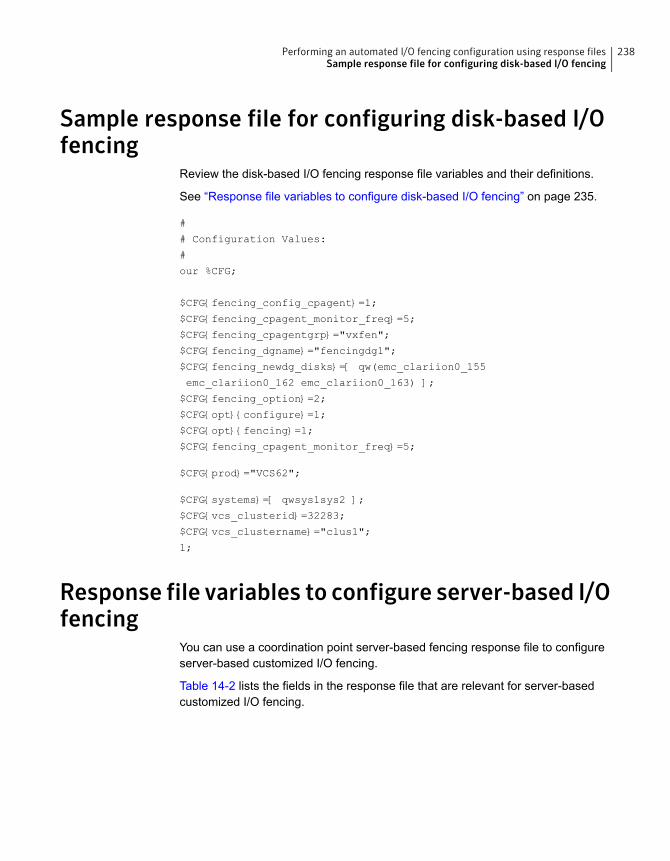
Sample response file for configuring disk-based I/Ofencing
Review the disk-based I/O fencing response file variables and their definitions.
See “Response file variables to configure disk-based I/O fencing” on page 235.
#
# Configuration Values:
#
our %CFG;
$CFG{fencing_config_cpagent}=1;
$CFG{fencing_cpagent_monitor_freq}=5;
$CFG{fencing_cpagentgrp}="vxfen";
$CFG{fencing_dgname}="fencingdg1";
$CFG{fencing_newdg_disks}=[ qw(emc_clariion0_155
emc_clariion0_162 emc_clariion0_163) ];
$CFG{fencing_option}=2;
$CFG{opt}{configure}=1;
$CFG{opt}{fencing}=1;
$CFG{fencing_cpagent_monitor_freq}=5;
$CFG{prod}="VCS62";
$CFG{systems}=[ qwsys1sys2 ];
$CFG{vcs_clusterid}=32283;
$CFG{vcs_clustername}="clus1";
1;
Response file variables to configure server-based I/Ofencing
You can use a coordination point server-based fencing response file to configureserver-based customized I/O fencing.
Table 14-2 lists the fields in the response file that are relevant for server-basedcustomized I/O fencing.
238Performing an automated I/O fencing configuration using response filesSample response file for configuring disk-based I/O fencing
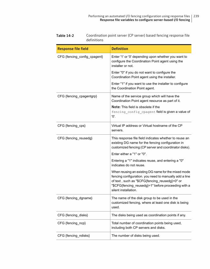
Table 14-2 Coordination point server (CP server) based fencing response filedefinitions
DefinitionResponse file field
Enter '1' or '0' depending upon whether you want toconfigure the Coordination Point agent using theinstaller or not.
Enter "0" if you do not want to configure theCoordination Point agent using the installer.
Enter "1" if you want to use the installer to configurethe Coordination Point agent.
CFG {fencing_config_cpagent}
Name of the service group which will have theCoordination Point agent resource as part of it.
Note: This field is obsolete if thefencing_config_cpagent field is given a value of'0'.
CFG {fencing_cpagentgrp}
Virtual IP address or Virtual hostname of the CPservers.
CFG {fencing_cps}
This response file field indicates whether to reuse anexisting DG name for the fencing configuration incustomized fencing (CP server and coordinator disks).
Enter either a "1" or "0".
Entering a "1" indicates reuse, and entering a "0"indicates do not reuse.
When reusing an existing DG name for the mixed modefencing configuration. you need to manually add a lineof text , such as "$CFG{fencing_reusedg}=0" or"$CFG{fencing_reusedg}=1" before proceeding with asilent installation.
CFG {fencing_reusedg}
The name of the disk group to be used in thecustomized fencing, where at least one disk is beingused.
CFG {fencing_dgname}
The disks being used as coordination points if any.CFG {fencing_disks}
Total number of coordination points being used,including both CP servers and disks.
CFG {fencing_ncp}
The number of disks being used.CFG {fencing_ndisks}
239Performing an automated I/O fencing configuration using response filesResponse file variables to configure server-based I/O fencing
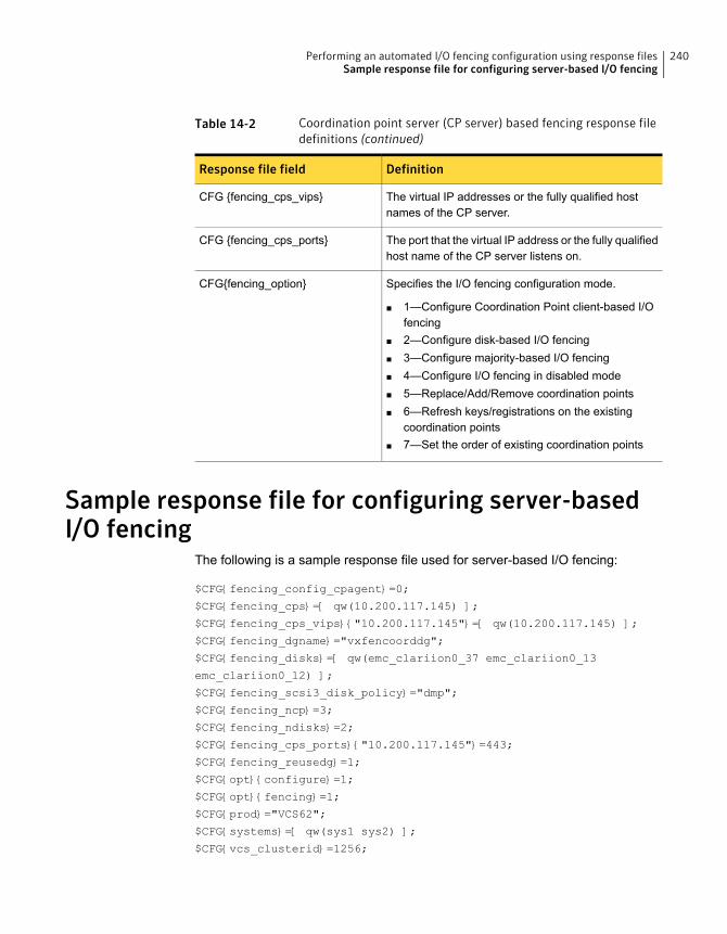
Table 14-2 Coordination point server (CP server) based fencing response filedefinitions (continued)
DefinitionResponse file field
The virtual IP addresses or the fully qualified hostnames of the CP server.
CFG {fencing_cps_vips}
The port that the virtual IP address or the fully qualifiedhost name of the CP server listens on.
CFG {fencing_cps_ports}
Specifies the I/O fencing configuration mode.
■ 1—Configure Coordination Point client-based I/Ofencing
■ 2—Configure disk-based I/O fencing■ 3—Configure majority-based I/O fencing■ 4—Configure I/O fencing in disabled mode■ 5—Replace/Add/Remove coordination points■ 6—Refresh keys/registrations on the existing
coordination points■ 7—Set the order of existing coordination points
CFG{fencing_option}
Sample response file for configuring server-basedI/O fencing
The following is a sample response file used for server-based I/O fencing:
$CFG{fencing_config_cpagent}=0;
$CFG{fencing_cps}=[ qw(10.200.117.145) ];
$CFG{fencing_cps_vips}{"10.200.117.145"}=[ qw(10.200.117.145) ];
$CFG{fencing_dgname}="vxfencoorddg";
$CFG{fencing_disks}=[ qw(emc_clariion0_37 emc_clariion0_13
emc_clariion0_12) ];
$CFG{fencing_scsi3_disk_policy}="dmp";
$CFG{fencing_ncp}=3;
$CFG{fencing_ndisks}=2;
$CFG{fencing_cps_ports}{"10.200.117.145"}=443;
$CFG{fencing_reusedg}=1;
$CFG{opt}{configure}=1;
$CFG{opt}{fencing}=1;
$CFG{prod}="VCS62";
$CFG{systems}=[ qw(sys1 sys2) ];
$CFG{vcs_clusterid}=1256;
240Performing an automated I/O fencing configuration using response filesSample response file for configuring server-based I/O fencing

$CFG{vcs_clustername}="clus1";
$CFG{fencing_option}=1;
Response file variables to configure non-SCSI-3 I/Ofencing
Table 14-3 lists the fields in the response file that are relevant for non-SCSI-3 I/Ofencing.
See “About I/O fencing for VCS in virtual machines that do not support SCSI-3 PR”on page 33.
Table 14-3 Non-SCSI-3 I/O fencing response file definitions
DefinitionResponse file field
Defines whether to configure non-SCSI-3 I/O fencing.
Valid values are 1 or 0. Enter 1 to configure non-SCSI-3I/O fencing.
CFG{non_scsi3_fencing}
Enter '1' or '0' depending upon whether you want toconfigure the Coordination Point agent using theinstaller or not.
Enter "0" if you do not want to configure theCoordination Point agent using the installer.
Enter "1" if you want to use the installer to configurethe Coordination Point agent.
Note: This variable does not apply to majority-basedfencing.
CFG {fencing_config_cpagent}
Name of the service group which will have theCoordination Point agent resource as part of it.
Note: This field is obsolete if thefencing_config_cpagent field is given a value of'0'. This variable does not apply to majority-basedfencing.
CFG {fencing_cpagentgrp}
Virtual IP address or Virtual hostname of the CPservers.
Note: This variable does not apply to majority-basedfencing.
CFG {fencing_cps}
241Performing an automated I/O fencing configuration using response filesResponse file variables to configure non-SCSI-3 I/O fencing
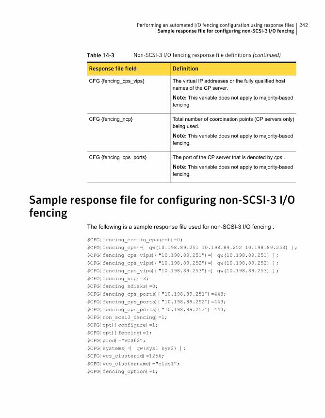
Table 14-3 Non-SCSI-3 I/O fencing response file definitions (continued)
DefinitionResponse file field
The virtual IP addresses or the fully qualified hostnames of the CP server.
Note: This variable does not apply to majority-basedfencing.
CFG {fencing_cps_vips}
Total number of coordination points (CP servers only)being used.
Note: This variable does not apply to majority-basedfencing.
CFG {fencing_ncp}
The port of the CP server that is denoted by cps .
Note: This variable does not apply to majority-basedfencing.
CFG {fencing_cps_ports}
Sample response file for configuring non-SCSI-3 I/Ofencing
The following is a sample response file used for non-SCSI-3 I/O fencing :
$CFG{fencing_config_cpagent}=0;
$CFG{fencing_cps}=[ qw(10.198.89.251 10.198.89.252 10.198.89.253) ];
$CFG{fencing_cps_vips}{"10.198.89.251"}=[ qw(10.198.89.251) ];
$CFG{fencing_cps_vips}{"10.198.89.252"}=[ qw(10.198.89.252) ];
$CFG{fencing_cps_vips}{"10.198.89.253"}=[ qw(10.198.89.253) ];
$CFG{fencing_ncp}=3;
$CFG{fencing_ndisks}=0;
$CFG{fencing_cps_ports}{"10.198.89.251"}=443;
$CFG{fencing_cps_ports}{"10.198.89.252"}=443;
$CFG{fencing_cps_ports}{"10.198.89.253"}=443;
$CFG{non_scsi3_fencing}=1;
$CFG{opt}{configure}=1;
$CFG{opt}{fencing}=1;
$CFG{prod}="VCS62";
$CFG{systems}=[ qw(sys1 sys2) ];
$CFG{vcs_clusterid}=1256;
$CFG{vcs_clustername}="clus1";
$CFG{fencing_option}=1;
242Performing an automated I/O fencing configuration using response filesSample response file for configuring non-SCSI-3 I/O fencing
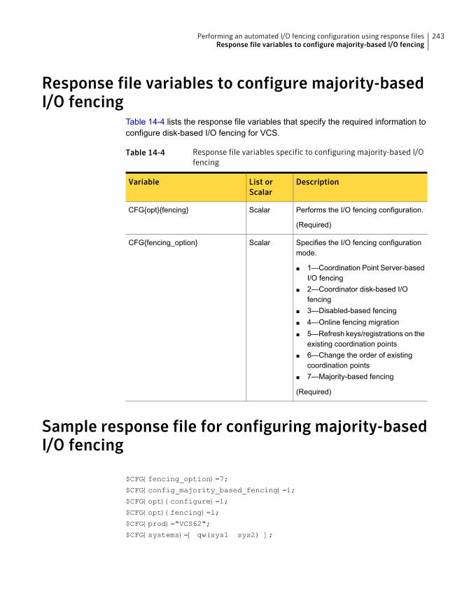
Response file variables to configure majority-basedI/O fencing
Table 14-4 lists the response file variables that specify the required information toconfigure disk-based I/O fencing for VCS.
Table 14-4 Response file variables specific to configuring majority-based I/Ofencing
DescriptionList orScalar
Variable
Performs the I/O fencing configuration.
(Required)
ScalarCFG{opt}{fencing}
Specifies the I/O fencing configurationmode.
■ 1—Coordination Point Server-basedI/O fencing
■ 2—Coordinator disk-based I/Ofencing
■ 3—Disabled-based fencing■ 4—Online fencing migration■ 5—Refresh keys/registrations on the
existing coordination points■ 6—Change the order of existing
coordination points■ 7—Majority-based fencing
(Required)
ScalarCFG{fencing_option}
Sample response file for configuring majority-basedI/O fencing
$CFG{fencing_option}=7;
$CFG{config_majority_based_fencing}=1;
$CFG{opt}{configure}=1;
$CFG{opt}{fencing}=1;
$CFG{prod}="VCS62";
$CFG{systems}=[ qw(sys1 sys2) ];
243Performing an automated I/O fencing configuration using response filesResponse file variables to configure majority-based I/O fencing

$CFG{vcs_clusterid}=59082;
$CFG{vcs_clustername}="clus1";
244Performing an automated I/O fencing configuration using response filesSample response file for configuring majority-based I/O fencing

Manual installation
■ Chapter 15. Performing preinstallation tasks
■ Chapter 16. Manually installing VCS
■ Chapter 17. Manually configuring VCS
■ Chapter 18. Manually configuring the clusters for data integrity
6Section
Performing preinstallationtasks
This chapter includes the following topics:
■ Requirements for installing VCS
Requirements for installing VCSReview requirements before you install.
See “Important preinstallation information for VCS” on page 38.
15Chapter
Manually installing VCS
This chapter includes the following topics:
■ About VCS manual installation
■ Installing VCS software manually
■ Installing VCS using Kickstart
■ Sample Kickstart configuration file
■ Installing Symantec Cluster Server using yum
■ Installing VCS using the Red Hat Satellite server
About VCS manual installationYou can manually install and configure VCS instead of using the installvcs.
A manual installation takes a lot of time, patience, and care. Symantec recommendsthat you use the installvcs instead of the manual installation when possible.
Installing VCS software manuallyTable 16-1 lists the tasks that you must perform when you manually install andconfigure VCS 6.2.
Table 16-1 Manual installation tasks for VCS 6.2
ReferenceTask
See “Installing VCS RPMs for a manual installation” on page 249.Install VCS softwaremanually on each node inthe cluster.
16Chapter
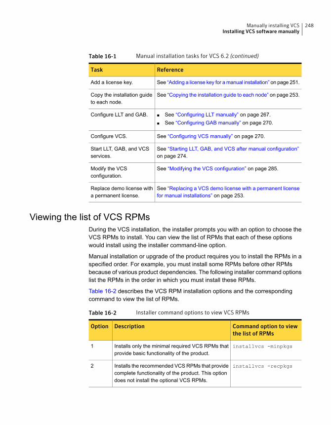
Table 16-1 Manual installation tasks for VCS 6.2 (continued)
ReferenceTask
See “Adding a license key for a manual installation” on page 251.Add a license key.
See “Copying the installation guide to each node” on page 253.Copy the installation guideto each node.
■ See “Configuring LLT manually” on page 267.■ See “Configuring GAB manually” on page 270.
Configure LLT and GAB.
See “Configuring VCS manually” on page 270.Configure VCS.
See “Starting LLT, GAB, and VCS after manual configuration”on page 274.
Start LLT, GAB, and VCSservices.
See “Modifying the VCS configuration” on page 285.Modify the VCSconfiguration.
See “Replacing a VCS demo license with a permanent licensefor manual installations” on page 253.
Replace demo license witha permanent license.
Viewing the list of VCS RPMsDuring the VCS installation, the installer prompts you with an option to choose theVCS RPMs to install. You can view the list of RPMs that each of these optionswould install using the installer command-line option.
Manual installation or upgrade of the product requires you to install the RPMs in aspecified order. For example, you must install some RPMs before other RPMsbecause of various product dependencies. The following installer command optionslist the RPMs in the order in which you must install these RPMs.
Table 16-2 describes the VCS RPM installation options and the correspondingcommand to view the list of RPMs.
Table 16-2 Installer command options to view VCS RPMs
Command option to viewthe list of RPMs
DescriptionOption
installvcs -minpkgsInstalls only the minimal required VCS RPMs thatprovide basic functionality of the product.
1
installvcs -recpkgsInstalls the recommended VCS RPMs that providecomplete functionality of the product. This optiondoes not install the optional VCS RPMs.
2
248Manually installing VCSInstalling VCS software manually
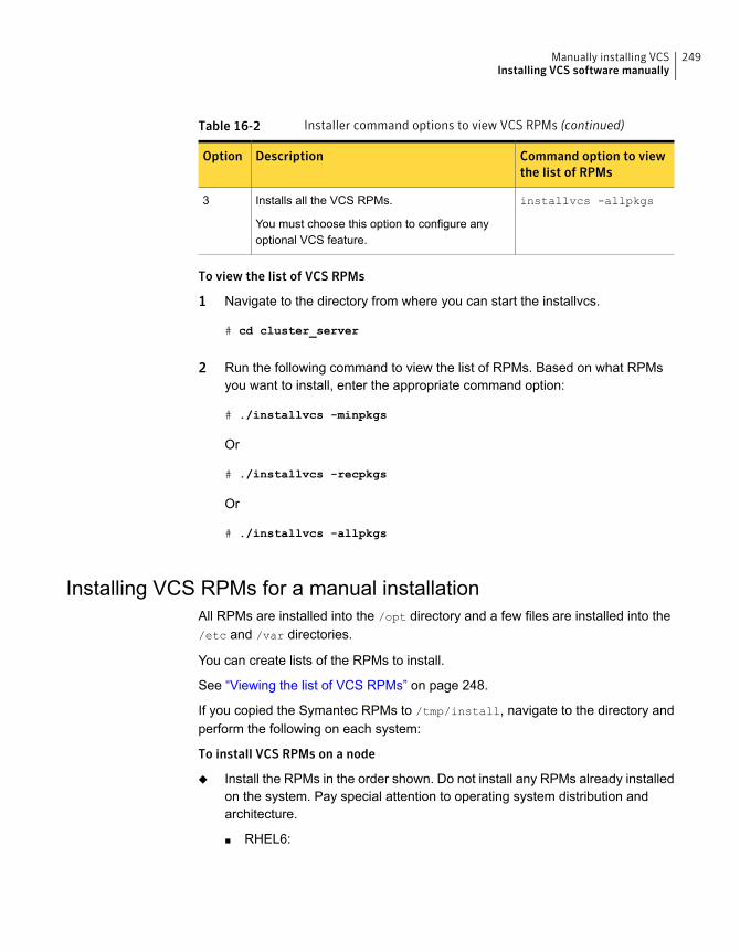
Table 16-2 Installer command options to view VCS RPMs (continued)
Command option to viewthe list of RPMs
DescriptionOption
installvcs -allpkgsInstalls all the VCS RPMs.
You must choose this option to configure anyoptional VCS feature.
3
To view the list of VCS RPMs
1 Navigate to the directory from where you can start the installvcs.
# cd cluster_server
2 Run the following command to view the list of RPMs. Based on what RPMsyou want to install, enter the appropriate command option:
# ./installvcs -minpkgs
Or
# ./installvcs -recpkgs
Or
# ./installvcs -allpkgs
Installing VCS RPMs for a manual installationAll RPMs are installed into the /opt directory and a few files are installed into the/etc and /var directories.
You can create lists of the RPMs to install.
See “Viewing the list of VCS RPMs” on page 248.
If you copied the Symantec RPMs to /tmp/install, navigate to the directory andperform the following on each system:
To install VCS RPMs on a node
◆ Install the RPMs in the order shown. Do not install any RPMs already installedon the system. Pay special attention to operating system distribution andarchitecture.
■ RHEL6:
249Manually installing VCSInstalling VCS software manually
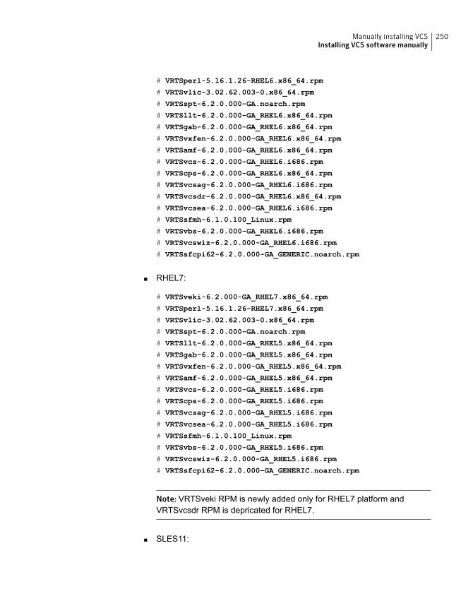
# VRTSperl-5.16.1.26-RHEL6.x86_64.rpm
# VRTSvlic-3.02.62.003-0.x86_64.rpm
# VRTSspt-6.2.0.000-GA.noarch.rpm
# VRTSllt-6.2.0.000-GA_RHEL6.x86_64.rpm
# VRTSgab-6.2.0.000-GA_RHEL6.x86_64.rpm
# VRTSvxfen-6.2.0.000-GA_RHEL6.x86_64.rpm
# VRTSamf-6.2.0.000-GA_RHEL6.x86_64.rpm
# VRTSvcs-6.2.0.000-GA_RHEL6.i686.rpm
# VRTScps-6.2.0.000-GA_RHEL6.x86_64.rpm
# VRTSvcsag-6.2.0.000-GA_RHEL6.i686.rpm
# VRTSvcsdr-6.2.0.000-GA_RHEL6.x86_64.rpm
# VRTSvcsea-6.2.0.000-GA_RHEL6.i686.rpm
# VRTSsfmh-6.1.0.100_Linux.rpm
# VRTSvbs-6.2.0.000-GA_RHEL6.i686.rpm
# VRTSvcswiz-6.2.0.000-GA_RHEL6.i686.rpm
# VRTSsfcpi62-6.2.0.000-GA_GENERIC.noarch.rpm
■ RHEL7:
# VRTSveki-6.2.000-GA_RHEL7.x86_64.rpm
# VRTSperl-5.16.1.26-RHEL7.x86_64.rpm
# VRTSvlic-3.02.62.003-0.x86_64.rpm
# VRTSspt-6.2.0.000-GA.noarch.rpm
# VRTSllt-6.2.0.000-GA_RHEL5.x86_64.rpm
# VRTSgab-6.2.0.000-GA_RHEL5.x86_64.rpm
# VRTSvxfen-6.2.0.000-GA_RHEL5.x86_64.rpm
# VRTSamf-6.2.0.000-GA_RHEL5.x86_64.rpm
# VRTSvcs-6.2.0.000-GA_RHEL5.i686.rpm
# VRTScps-6.2.0.000-GA_RHEL5.i686.rpm
# VRTSvcsag-6.2.0.000-GA_RHEL5.i686.rpm
# VRTSvcsea-6.2.0.000-GA_RHEL5.i686.rpm
# VRTSsfmh-6.1.0.100_Linux.rpm
# VRTSvbs-6.2.0.000-GA_RHEL5.i686.rpm
# VRTSvcswiz-6.2.0.000-GA_RHEL5.i686.rpm
# VRTSsfcpi62-6.2.0.000-GA_GENERIC.noarch.rpm
Note: VRTSveki RPM is newly added only for RHEL7 platform andVRTSvcsdr RPM is depricated for RHEL7.
■ SLES11:
250Manually installing VCSInstalling VCS software manually
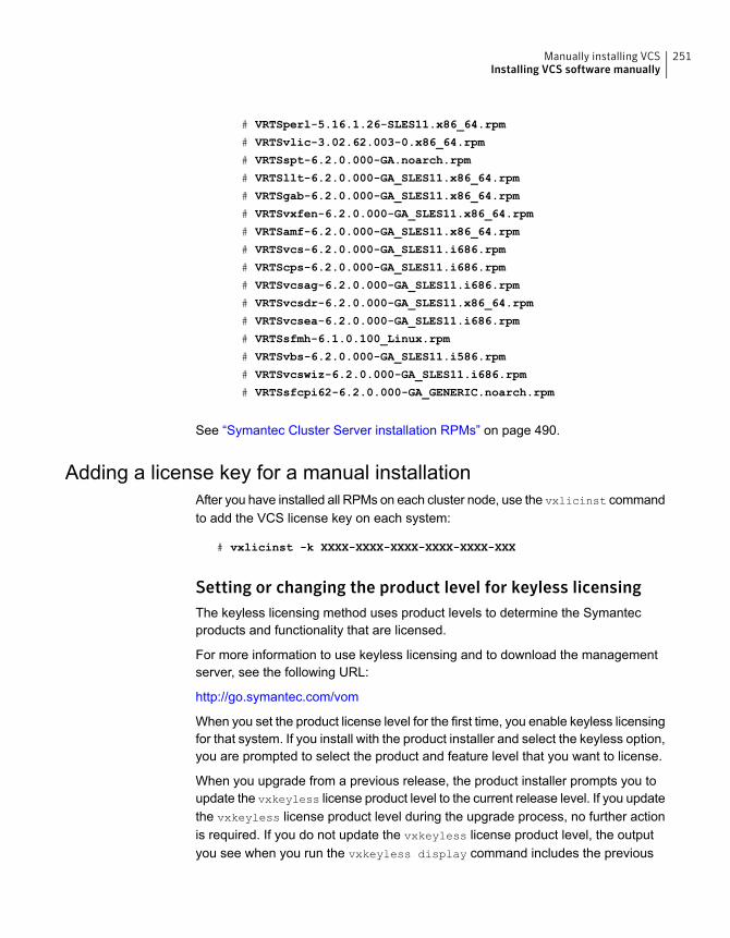
# VRTSperl-5.16.1.26-SLES11.x86_64.rpm
# VRTSvlic-3.02.62.003-0.x86_64.rpm
# VRTSspt-6.2.0.000-GA.noarch.rpm
# VRTSllt-6.2.0.000-GA_SLES11.x86_64.rpm
# VRTSgab-6.2.0.000-GA_SLES11.x86_64.rpm
# VRTSvxfen-6.2.0.000-GA_SLES11.x86_64.rpm
# VRTSamf-6.2.0.000-GA_SLES11.x86_64.rpm
# VRTSvcs-6.2.0.000-GA_SLES11.i686.rpm
# VRTScps-6.2.0.000-GA_SLES11.i686.rpm
# VRTSvcsag-6.2.0.000-GA_SLES11.i686.rpm
# VRTSvcsdr-6.2.0.000-GA_SLES11.x86_64.rpm
# VRTSvcsea-6.2.0.000-GA_SLES11.i686.rpm
# VRTSsfmh-6.1.0.100_Linux.rpm
# VRTSvbs-6.2.0.000-GA_SLES11.i586.rpm
# VRTSvcswiz-6.2.0.000-GA_SLES11.i686.rpm
# VRTSsfcpi62-6.2.0.000-GA_GENERIC.noarch.rpm
See “Symantec Cluster Server installation RPMs” on page 490.
Adding a license key for a manual installationAfter you have installed all RPMs on each cluster node, use the vxlicinst commandto add the VCS license key on each system:
# vxlicinst -k XXXX-XXXX-XXXX-XXXX-XXXX-XXX
Setting or changing the product level for keyless licensingThe keyless licensing method uses product levels to determine the Symantecproducts and functionality that are licensed.
For more information to use keyless licensing and to download the managementserver, see the following URL:
http://go.symantec.com/vom
When you set the product license level for the first time, you enable keyless licensingfor that system. If you install with the product installer and select the keyless option,you are prompted to select the product and feature level that you want to license.
When you upgrade from a previous release, the product installer prompts you toupdate the vxkeyless license product level to the current release level. If you updatethe vxkeyless license product level during the upgrade process, no further actionis required. If you do not update the vxkeyless license product level, the outputyou see when you run the vxkeyless display command includes the previous
251Manually installing VCSInstalling VCS software manually
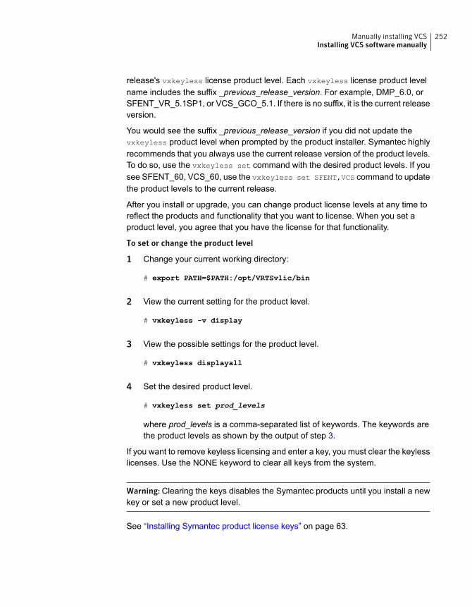
release's vxkeyless license product level. Each vxkeyless license product levelname includes the suffix _previous_release_version. For example, DMP_6.0, orSFENT_VR_5.1SP1, or VCS_GCO_5.1. If there is no suffix, it is the current releaseversion.
You would see the suffix _previous_release_version if you did not update thevxkeyless product level when prompted by the product installer. Symantec highlyrecommends that you always use the current release version of the product levels.To do so, use the vxkeyless set command with the desired product levels. If yousee SFENT_60, VCS_60, use the vxkeyless set SFENT,VCS command to updatethe product levels to the current release.
After you install or upgrade, you can change product license levels at any time toreflect the products and functionality that you want to license. When you set aproduct level, you agree that you have the license for that functionality.
To set or change the product level
1 Change your current working directory:
# export PATH=$PATH:/opt/VRTSvlic/bin
2 View the current setting for the product level.
# vxkeyless -v display
3 View the possible settings for the product level.
# vxkeyless displayall
4 Set the desired product level.
# vxkeyless set prod_levels
where prod_levels is a comma-separated list of keywords. The keywords arethe product levels as shown by the output of step 3.
If you want to remove keyless licensing and enter a key, you must clear the keylesslicenses. Use the NONE keyword to clear all keys from the system.
Warning: Clearing the keys disables the Symantec products until you install a newkey or set a new product level.
See “Installing Symantec product license keys” on page 63.
252Manually installing VCSInstalling VCS software manually
To clear the product license level
1 View the current setting for the product license level.
# vxkeyless [-v] display
2 If there are keyless licenses installed, remove all keyless licenses:
# vxkeyless [-q] set NONE
For more details on using the vxkeyless utility, see the vxkeyless(1m) manualpage.
Checking licensing information on the system for a manualinstallationUse the vxlicrep utility to display information about all Symantec licenses on asystem. For example, enter:
# vxlicrep
From the output, you can determine the following:
■ The license key
■ The type of license
■ The product for which it applies
■ Its expiration date, if one existsDemo keys have expiration dates, while permanent keys and site keys do not.
Replacing a VCS demo license with a permanent license formanual installationsWhen a VCS demo key license expires, you can replace it with a permanent licenseusing the vxlicinst program.
See “Checking licensing information on the system” on page 155.
Copying the installation guide to each nodeAfter you install VCS, Symantec recommends that you copy the PDF version ofthis guide from the installation disc to the /opt/VRTS/docs directory on each nodeto make it available for reference. The PDF is located atdocs/cluster_server/vcs_install_version_platform.pdf where version isthe release version and platform is the name of the operating system.
253Manually installing VCSInstalling VCS software manually
Installing VCS using KickstartYou can install VCS using Kickstart. Kickstart is supported for Red Hat EnterpriseLinux operating system.
To install VCS using Kickstart
1 Create a directory for the Kickstart configuration files.
# mkdir /kickstart_files/
2 Generate the Kickstart configuration files. The configuration files have theextension .ks. Do one of the following:
■ To generate configuration files, enter the following command:
# ./installer -kickstart /kickstart_files/
The system lists the files.
■ To only generate the configuration file for VCS, enter the following command:
# ./installvcs -kickstart /kickstart_files/
The command output includes the following:
The kickstart script for VCS is generated at
/kickstart_files/kickstart_vcs62.ks
3 Set up an NFS exported location which the Kickstart client can access. Forexample, if /nfs_mount_kickstart is the directory which has been NFSexported, the NFS exported location may look similar to the following:
# cat /etc/exports
/nfs_mount_kickstart * (rw,sync,no_root_squash)
4 Copy the rpms directory from the installation media to the NFS location.
5 Verify the contents of the directory.
# ls /nfs_mount_kickstart/
6 In the VCS Kickstart configuration file, modify the BUILDSRC variable to pointto the actual NFS location. The variable has the following format:
BUILDSRC="hostname_or_ip:/nfs_mount_kickstart"
254Manually installing VCSInstalling VCS using Kickstart
7 Append the entire modified contents of the Kickstart configuration file to theoperating system ks.cfg file.
8 Launch the Kickstart installation for the operating system.
9 After the operating system installation is complete, check the file/var/tmp/kickstart.log for any errors that are related to the installation ofRPMs and product installer scripts.
10 Verify that all the product RPMs have been installed. Enter the followingcommand:
# rpm -qa | grep -i vrts
11 If you do not find any installation issues or errors, configure the product stack.Enter the following command:
# /opt/VRTS/install/installvcs<version> -configure node1 node2
Where <version> is the specific release version.
See “About the script-based installer” on page 49.
12 Verify that all the configured llt links and gab ports have started.
For VCS, ports a and h should be open. Port b might be open depending if youconfigured fencing or not. The following command displays the ports that areopened for VCS:
# gabconfig -a
GAB Port Memberships
===============================================================
Port a gen 6e6e03 membership 01
Port h gen 6e6e06 membership 01
255Manually installing VCSInstalling VCS using Kickstart
13 Verify that the product is configured properly by entering commands such ashastatus and lltstat -n.
# hastatus -sum
-- SYSTEM STATE
-- System State Frozen
A sys1 RUNNING 0
A sys2 RUNNING 0
# lltstat -n
LLT node information:
Node State Links
0 sys1 OPEN 2
* 1 sys2 OPEN 2
14 If you configure the node in a secured mode, verify the status. For example:
# haclus -value SecureClus
1
Sample Kickstart configuration fileThe following is a sample RedHat Enterprise Linux 6 (RHEL6) Kickstart configurationfile.
# The packages below are required and will be installed
from OS installation media automatically # during the automated
installation of products in the DVD, if they have not been
installed yet.
%packages
systemd-libs.i686
device-mapper
device-mapper-libs
parted
libgcc.i686
ed
ksh
nss-softokn-freebl.i686
glibc.i686
libstdc++.i686
audit-libs.i686
256Manually installing VCSSample Kickstart configuration file
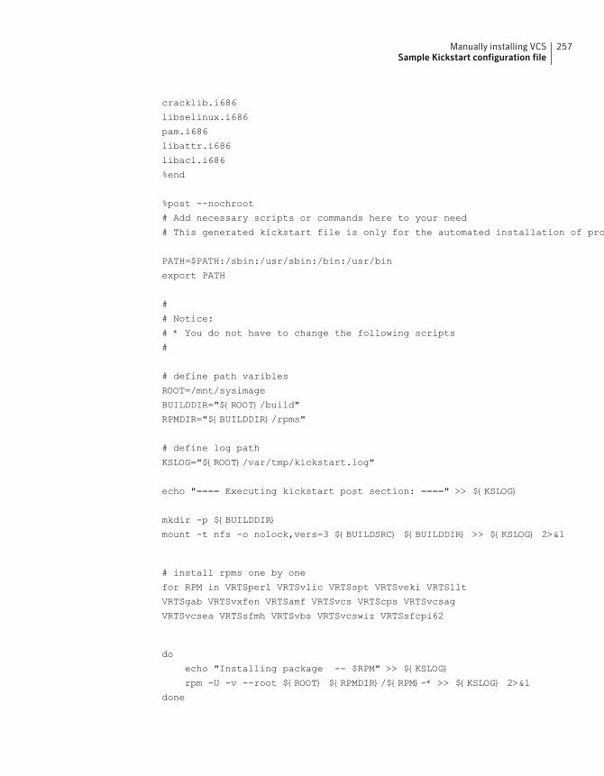
cracklib.i686
libselinux.i686
pam.i686
libattr.i686
libacl.i686
%end
%post --nochroot
# Add necessary scripts or commands here to your need
# This generated kickstart file is only for the automated installation of products in the DVD
PATH=$PATH:/sbin:/usr/sbin:/bin:/usr/bin
export PATH
#
# Notice:
# * You do not have to change the following scripts
#
# define path varibles
ROOT=/mnt/sysimage
BUILDDIR="${ROOT}/build"
RPMDIR="${BUILDDIR}/rpms"
# define log path
KSLOG="${ROOT}/var/tmp/kickstart.log"
echo "==== Executing kickstart post section: ====" >> ${KSLOG}
mkdir -p ${BUILDDIR}
mount -t nfs -o nolock,vers=3 ${BUILDSRC} ${BUILDDIR} >> ${KSLOG} 2>&1
# install rpms one by one
for RPM in VRTSperl VRTSvlic VRTSspt VRTSveki VRTSllt
VRTSgab VRTSvxfen VRTSamf VRTSvcs VRTScps VRTSvcsag
VRTSvcsea VRTSsfmh VRTSvbs VRTSvcswiz VRTSsfcpi62
do
echo "Installing package -- $RPM" >> ${KSLOG}
rpm -U -v --root ${ROOT} ${RPMDIR}/${RPM}-* >> ${KSLOG} 2>&1
done
257Manually installing VCSSample Kickstart configuration file
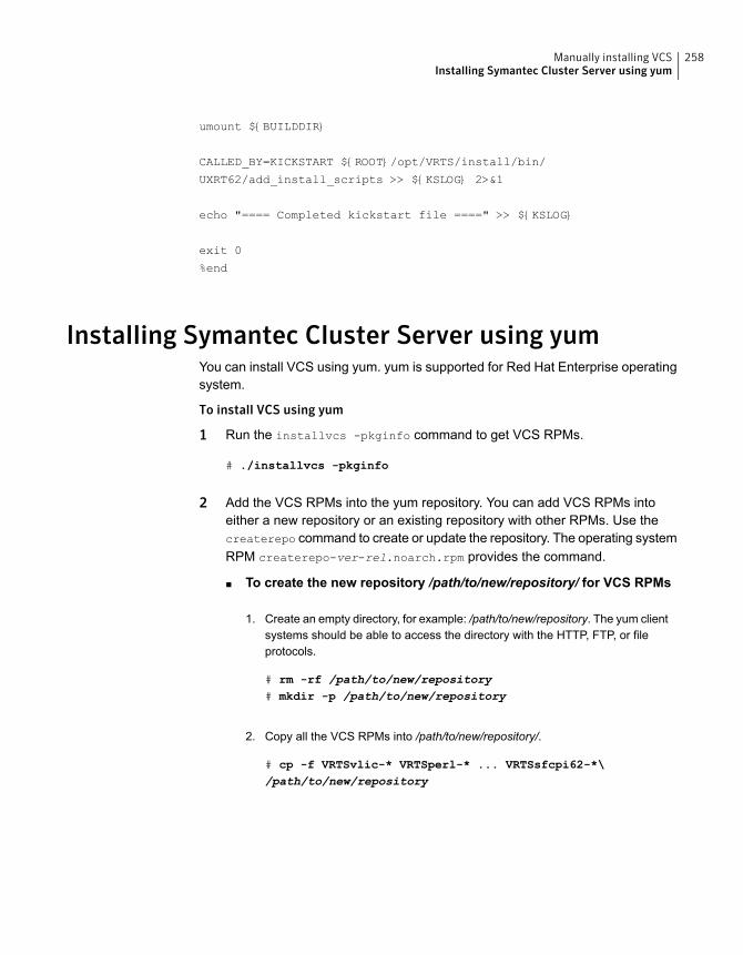
umount ${BUILDDIR}
CALLED_BY=KICKSTART ${ROOT}/opt/VRTS/install/bin/
UXRT62/add_install_scripts >> ${KSLOG} 2>&1
echo "==== Completed kickstart file ====" >> ${KSLOG}
exit 0
%end
Installing Symantec Cluster Server using yumYou can install VCS using yum. yum is supported for Red Hat Enterprise operatingsystem.
To install VCS using yum
1 Run the installvcs -pkginfo command to get VCS RPMs.
# ./installvcs -pkginfo
2 Add the VCS RPMs into the yum repository. You can add VCS RPMs intoeither a new repository or an existing repository with other RPMs. Use thecreaterepo command to create or update the repository. The operating systemRPM createrepo-ver-rel.noarch.rpm provides the command.
■ To create the new repository /path/to/new/repository/ for VCS RPMs
Create an empty directory, for example: /path/to/new/repository. The yum clientsystems should be able to access the directory with the HTTP, FTP, or fileprotocols.
# rm -rf /path/to/new/repository# mkdir -p /path/to/new/repository
1.
Copy all the VCS RPMs into /path/to/new/repository/.
# cp -f VRTSvlic-* VRTSperl-* ... VRTSsfcpi62-*\/path/to/new/repository
2.
258Manually installing VCSInstalling Symantec Cluster Server using yum
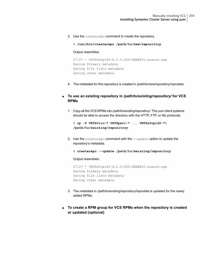
Use the createrepo command to create the repository.
# /usr/bin/createrepo /path/to/new/repository
Output resembles:
27/27 - VRTSsfcpi62-6.2.0.000-GENERIC.noarch.rpmSaving Primary metadataSaving file lists metadataSaving other metadata
3.
The metadata for this repository is created in /path/to/new/repository/repodata.4.
■ To use an existing repository in /path/to/existing/repository/ for VCSRPMs
Copy all the VCS RPMs into /path/to/existing/repository/. The yum client systemsshould be able to access the directory with the HTTP, FTP, or file protocols.
# cp -f VRTSvlic-* VRTSperl-* ... VRTSsfcpi62-*\/path/to/existing/repository
1.
Use the createrepo command with the --update option to update therepository's metadata.
# createrepo --update /path/to/existing/repository
Output resembles:
27/27 * VRTSsfcpi62-6.2.0.000-GENERIC.noarch.rpmSaving Primary metadataSaving file lists metadataSaving other metadata
2.
The metadata in /path/to/existing/repository/repodata is updated for the newlyadded RPMs.
3.
■ To create a RPM group for VCS RPMs when the repository is createdor updated (optional)
259Manually installing VCSInstalling Symantec Cluster Server using yum
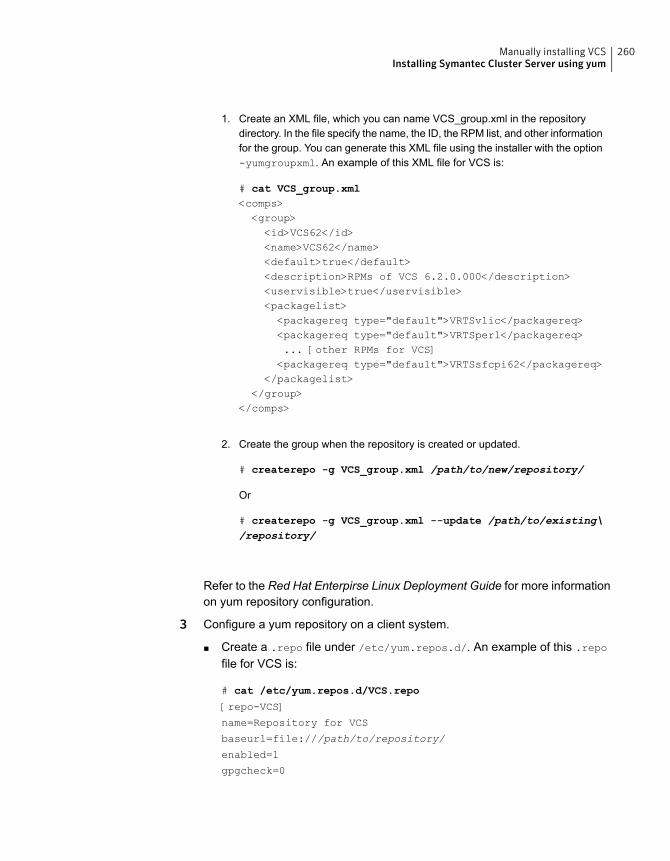
Create an XML file, which you can name VCS_group.xml in the repositorydirectory. In the file specify the name, the ID, the RPM list, and other informationfor the group. You can generate this XML file using the installer with the option-yumgroupxml. An example of this XML file for VCS is:
# cat VCS_group.xml<comps><group><id>VCS62</id><name>VCS62</name><default>true</default><description>RPMs of VCS 6.2.0.000</description><uservisible>true</uservisible><packagelist><packagereq type="default">VRTSvlic</packagereq><packagereq type="default">VRTSperl</packagereq>... [other RPMs for VCS]<packagereq type="default">VRTSsfcpi62</packagereq>
</packagelist></group>
</comps>
1.
Create the group when the repository is created or updated.
# createrepo -g VCS_group.xml /path/to/new/repository/
Or
# createrepo -g VCS_group.xml --update /path/to/existing\/repository/
2.
Refer to the Red Hat Enterpirse Linux Deployment Guide for more informationon yum repository configuration.
3 Configure a yum repository on a client system.
■ Create a .repo file under /etc/yum.repos.d/. An example of this .repo
file for VCS is:
# cat /etc/yum.repos.d/VCS.repo
[repo-VCS]
name=Repository for VCS
baseurl=file:///path/to/repository/
enabled=1
gpgcheck=0
260Manually installing VCSInstalling Symantec Cluster Server using yum
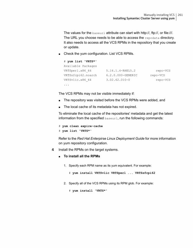
The values for the baseurl attribute can start with http://, ftp://, or file:///.The URL you choose needs to be able to access the repodata directory.It also needs to access all the VCS RPMs in the repository that you createor update.
■ Check the yum configuration. List VCS RPMs.
# yum list 'VRTS*'
Available Packages
VRTSperl.x86_64 5.16.1.4-RHEL5.2 repo-VCS
VRTSsfcpi62.noarch 6.2.0.000-GENERIC repo-VCS
VRTSvlic.x86_64 3.02.62.010-0 repo-VCS
...
The VCS RPMs may not be visible immediately if:
■ The repository was visited before the VCS RPMs were added, and
■ The local cache of its metadata has not expired.
To eliminate the local cache of the repositories' metadata and get the latestinformation from the specified baseurl, run the following commands:
# yum clean expire-cache
# yum list 'VRTS*'
Refer to the Red Hat Enterpirse Linux Deployment Guide for more informationon yum repository configuration.
4 Install the RPMs on the target systems.
■ To install all the RPMs
Specify each RPM name as its yum equivalent. For example:
# yum install VRTSvlic VRTSperl ... VRTSsfcpi62
1.
Specify all of the VCS RPMs using its RPM glob. For example:
# yum install 'VRTS*'
2.
261Manually installing VCSInstalling Symantec Cluster Server using yum
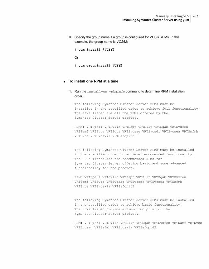
Specify the group name if a group is configured for VCS's RPMs. In thisexample, the group name is VCS62:
# yum install @VCS62
Or
# yum groupinstall VCS62
3.
■ To install one RPM at a time
Run the installvcs -pkginfo command to determine RPM installationorder.
The following Symantec Cluster Server RPMs must beinstalled in the specified order to achieve full functionality.The RPMs listed are all the RPMs offered by theSymantec Cluster Server product.
RPMs: VRTSperl VRTSvlic VRTSspt VRTSllt VRTSgab VRTSvxfenVRTSamf VRTSvcs VRTScps VRTSvcsag VRTSvcsdr VRTSvcsea VRTSsfmhVRTSvbs VRTSvcswiz VRTSsfcpi62
The following Symantec Cluster Server RPMs must be installedin the specified order to achieve recommended functionality.The RPMs listed are the recommended RPMs forSymantec Cluster Server offering basic and some advancedfunctionality for the product.
RPM: VRTSperl VRTSvlic VRTSspt VRTSllt VRTSgab VRTSvxfenVRTSamf VRTSvcs VRTSvcsag VRTSvcsdr VRTSvcsea VRTSsfmhVRTSvbs VRTSvcswiz VRTSsfcpi62
The following Symantec Cluster Server RPMs must be installedin the specified order to achieve basic functionality.The RPMs listed provide minimum footprint of theSymantec Cluster Server product.
RPM: VRTSperl VRTSvlic VRTSllt VRTSgab VRTSvxfen VRTSamf VRTSvcsVRTSvcsag VRTSsfmh VRTSvcswiz VRTSsfcpi62
1.
262Manually installing VCSInstalling Symantec Cluster Server using yum
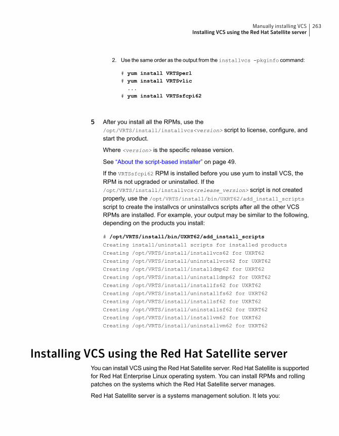
Use the same order as the output from the installvcs -pkginfo command:
# yum install VRTSperl# yum install VRTSvlic...
# yum install VRTSsfcpi62
2.
5 After you install all the RPMs, use the/opt/VRTS/install/installvcs<version> script to license, configure, andstart the product.
Where <version> is the specific release version.
See “About the script-based installer” on page 49.
If the VRTSsfcpi62 RPM is installed before you use yum to install VCS, theRPM is not upgraded or uninstalled. If the/opt/VRTS/install/installvcs<release_version> script is not createdproperly, use the /opt/VRTS/install/bin/UXRT62/add_install_scripts
script to create the installvcs or uninstallvcs scripts after all the other VCSRPMs are installed. For example, your output may be similar to the following,depending on the products you install:
# /opt/VRTS/install/bin/UXRT62/add_install_scripts
Creating install/uninstall scripts for installed products
Creating /opt/VRTS/install/installvcs62 for UXRT62
Creating /opt/VRTS/install/uninstallvcs62 for UXRT62
Creating /opt/VRTS/install/installdmp62 for UXRT62
Creating /opt/VRTS/install/uninstalldmp62 for UXRT62
Creating /opt/VRTS/install/installfs62 for UXRT62
Creating /opt/VRTS/install/uninstallfs62 for UXRT62
Creating /opt/VRTS/install/installsf62 for UXRT62
Creating /opt/VRTS/install/uninstallsf62 for UXRT62
Creating /opt/VRTS/install/installvm62 for UXRT62
Creating /opt/VRTS/install/uninstallvm62 for UXRT62
Installing VCS using the Red Hat Satellite serverYou can install VCS using the Red Hat Satellite server. Red Hat Satellite is supportedfor Red Hat Enterprise Linux operating system. You can install RPMs and rollingpatches on the systems which the Red Hat Satellite server manages.
Red Hat Satellite server is a systems management solution. It lets you:
263Manually installing VCSInstalling VCS using the Red Hat Satellite server
■ Inventory the hardware and the software information of your systems.
■ Install and update software on systems.
■ Collect and distribute custom software RPMs into manageable groups.
■ Provision (Kickstart) systems.
■ Manage and deploy configuration files to systems.
■ Monitor your systems.
■ Provision virtual guests.
■ Start, stop, and configure virtual guests.
In a Red Hat Satellite server, you can manage the system by creating a channel.A Red Hat Satellite channel is a collection of software RPMs. Using channels, youcan segregate the RPMs by defining some rules. For instance, a channel maycontain RPMs only from a specific Red Hat distribution. You can define channelsaccording to your own requirement. You can create a channel that contains VCSRPMs for custom usage in your organization's network.
Channels are of two types:
■ Base channelA base channel consists of RPMs based on a specific architecture and Red HatEnterprise Linux release.
■ Child channelA child channel is a channel which is associated with a base channel thatcontains extra custom RPMs like VCS.
A system can subscribe to only one base channel and multiple child channels ofits base channel. The subscribed system can only install or update the RPMs thatare available through its satellite channels.
For more information, see the Red Hat Satellite5.6 User Guide.
Using Red Hat Satellite server to install VCS productsYou can use the Red Hat Satellite server to install VCS products on your system.
To use Red Hat Satellite server to install VCS products
1 Set the base channel, child channel, and target system by following the RedHat Satellite documentation. You need to ensure that:
■ The base channel consists of RPMs based on RHEL6.3, RHEL6.4,RHEL6.5, or the RHEL7 release
■ The child channel consists of VCS RPMs or patches.
264Manually installing VCSInstalling VCS using the Red Hat Satellite server

■ The target system is registered to the Red Hat Satellite.
2 Log on to the Red Hat Satellite admin page. Select the Systems tab. Click onthe target system.
3 Select Alter Channel Subscriptions to alter the channel subscription of thetarget system.
4 Select the channel which contains the repository of VCS.
5 Enter the following command to check the YUM repository on the target system.
# yum repolist
6 Enter the following command to install the VCS RPMs using YUM:
# yum install @VCS62
7 Enter the following command to generate the script of the installer:
# /opt/VRTS/install/bin/UXRT62/add_install_scripts
8 Enter the following command to configure VCS using the installer:
# ./installvcs62 -configure
265Manually installing VCSInstalling VCS using the Red Hat Satellite server
Manually configuring VCS
This chapter includes the following topics:
■ About configuring VCS manually
■ Configuring LLT manually
■ Configuring GAB manually
■ Configuring VCS manually
■ Configuring VCS in single node mode
■ Starting LLT, GAB, and VCS after manual configuration
■ About configuring cluster using VCS Cluster Configuration wizard
■ Before configuring a VCS cluster using the VCS Cluster Configuration wizard
■ Launching the VCS Cluster Configuration wizard
■ Configuring a cluster by using the VCS cluster configuration wizard
■ Adding a system to a VCS cluster
■ Modifying the VCS configuration
About configuring VCS manuallyThis section describes the procedures to manually configure VCS.
Note:For manually configuring VCS in single node mode, you can skip steps aboutconfiguring LLT manually and configuring GAB manually.
17Chapter
Configuring LLT manuallyVCS uses the Low Latency Transport (LLT) protocol for all cluster communicationsas a high-performance, low-latency replacement for the IP stack. LLT has two majorfunctions.
It handles the following tasks:
■ Traffic distribution
■ Heartbeat traffic
To configure LLT over Ethernet, perform the following steps on each node in thecluster:
■ Set up the file /etc/llthosts.See “Setting up /etc/llthosts for a manual installation” on page 267.
■ Set up the file /etc/llttab.See “Setting up /etc/llttab for a manual installation” on page 268.
■ Edit the following file on each node in the cluster to change the values of theLLT_START and the LLT_STOP environment variables to 1:/etc/sysconfig/llt
You can also configure LLT over UDP.
See “Using the UDP layer for LLT” on page 523.
You can also configure LLT over RDMA.
See “Using LLT over RDMA: supported use cases ” on page 538.
Setting up /etc/llthosts for a manual installationThe file llthosts(4) is a database. It contains one entry per system that links the LLTsystem ID (in the first column) with the LLT host name. You must ensure thatcontents of this file are identical on all the nodes in the cluster. A mismatch of thecontents of the file can cause indeterminate behavior in the cluster.
Use vi or another editor, to create the file /etc/llthosts that contains the entries thatresemble:
0 sys1
1 sys2
267Manually configuring VCSConfiguring LLT manually

Setting up /etc/llttab for a manual installationThe /etc/llttab file must specify the system’s ID number (or its node name), its clusterID, and the network links that correspond to the system. In addition, the file cancontain other directives. Refer also to the sample llttab file in /opt/VRTSllt.
See “About LLT directives in /etc/llttab file” on page 268.
Use vi or another editor to create the file /etc/llttab that contains the entries thatresemble:
set-node node_name
set-cluster cluster_id
link eth1 eth-MAC_address - ether - -
link eth2 eth-MAC_address - ether - -
The first line must identify the system where the file exists. In the example, thevalue for set-node can be: sys1 or 0. The next line, beginning with the set-cluster
command, identifies the cluster number, which must be a unique number whenmore than one cluster is configured on the same physical network connection. Thenext two lines, beginning with the link command, identify the two private networkcards that the LLT protocol uses. The order of directives must be the same as inthe sample llttab file in /opt/VRTSllt.
If you use different media speed for the private NICs, Symantec recommends thatyou configure the NICs with lesser speed as low-priority links to enhance LLTperformance. For example:
Use vi or another editor to create the file /etc/llttab that contains the entries thatresemble:
set-node node name
set-cluster cluster_id
link eth1 eth-MAC_address - ether - -
link eth2 eth-MAC_address - ether - -
link-lowpri eth3 eth-MAC_address - ether - -
See “Setting up the private network” on page 67.
About LLT directives in /etc/llttab fileTable 17-1 lists the LLT directives in /etc/llttab file for LLT over Ethernet.
268Manually configuring VCSConfiguring LLT manually
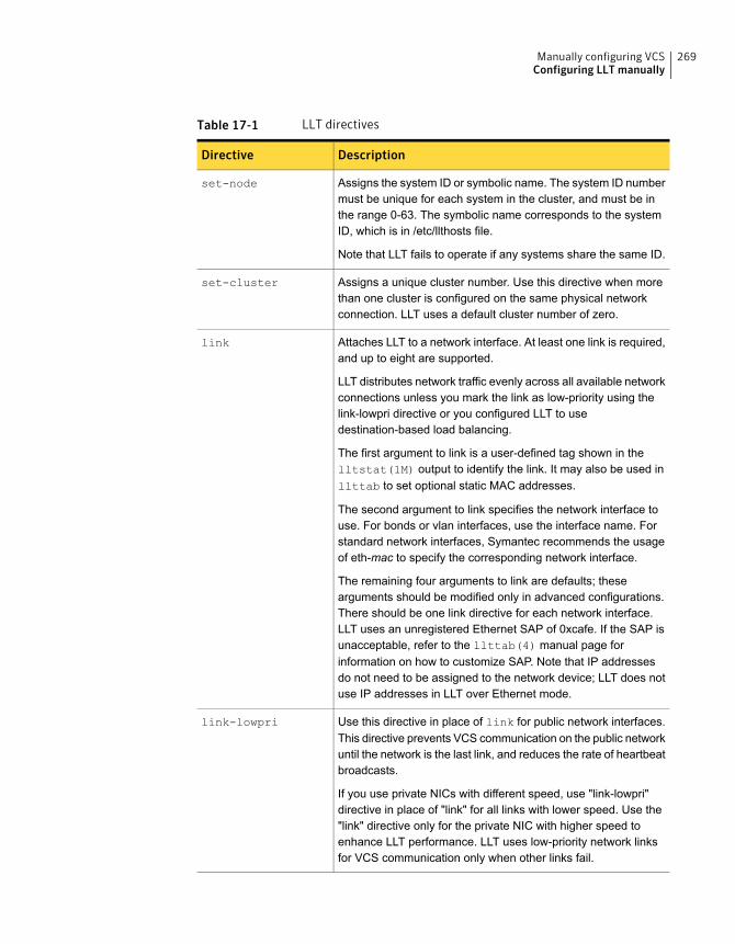
Table 17-1 LLT directives
DescriptionDirective
Assigns the system ID or symbolic name. The system ID numbermust be unique for each system in the cluster, and must be inthe range 0-63. The symbolic name corresponds to the systemID, which is in /etc/llthosts file.
Note that LLT fails to operate if any systems share the same ID.
set-node
Assigns a unique cluster number. Use this directive when morethan one cluster is configured on the same physical networkconnection. LLT uses a default cluster number of zero.
set-cluster
Attaches LLT to a network interface. At least one link is required,and up to eight are supported.
LLT distributes network traffic evenly across all available networkconnections unless you mark the link as low-priority using thelink-lowpri directive or you configured LLT to usedestination-based load balancing.
The first argument to link is a user-defined tag shown in thelltstat(1M) output to identify the link. It may also be used inllttab to set optional static MAC addresses.
The second argument to link specifies the network interface touse. For bonds or vlan interfaces, use the interface name. Forstandard network interfaces, Symantec recommends the usageof eth-mac to specify the corresponding network interface.
The remaining four arguments to link are defaults; thesearguments should be modified only in advanced configurations.There should be one link directive for each network interface.LLT uses an unregistered Ethernet SAP of 0xcafe. If the SAP isunacceptable, refer to the llttab(4) manual page forinformation on how to customize SAP. Note that IP addressesdo not need to be assigned to the network device; LLT does notuse IP addresses in LLT over Ethernet mode.
link
Use this directive in place of link for public network interfaces.This directive prevents VCS communication on the public networkuntil the network is the last link, and reduces the rate of heartbeatbroadcasts.
If you use private NICs with different speed, use "link-lowpri"directive in place of "link" for all links with lower speed. Use the"link" directive only for the private NIC with higher speed toenhance LLT performance. LLT uses low-priority network linksfor VCS communication only when other links fail.
link-lowpri
269Manually configuring VCSConfiguring LLT manually
For more information about the LLT directives, refer to the llttab(4) manual page.
Additional considerations for LLT for a manual installationYou must attach each network interface that is configured for LLT to a separateand distinct physical network.
Configuring GAB manuallyVCS uses the Group Membership Services/Atomic Broadcast (GAB) protocol forcluster membership and reliable cluster communications. GAB has two majorfunctions.
It handles the following tasks:
■ Cluster membership
■ Cluster communications
To configure GAB
1 Set up an /etc/gabtab configuration file on each node in the cluster using vi oranother editor. The following example shows an /etc/gabtab file:
/sbin/gabconfig -c -nN
Where the -c option configures the driver for use. The -nN option specifiesthat the cluster is not formed until at least N systems are ready to form thecluster. Symantec recommends that you set N to be the total number of systemsin the cluster.
Warning: Symantec does not recommend the use of the -c -x option or -xoption for /sbin/gabconfig. Using -c -x or -x can lead to a split-braincondition.
2 Edit the following file on each node in the cluster to change the values of theGAB_START and the GAB_STOP environment variables to 1:
/etc/sysconfig/gab
Configuring VCS manuallyVCS configuration requires the types.cf and main.cf files on each system in thecluster. Both of the files are in the /etc/VRTSvcs/conf/config directory.
270Manually configuring VCSConfiguring GAB manually
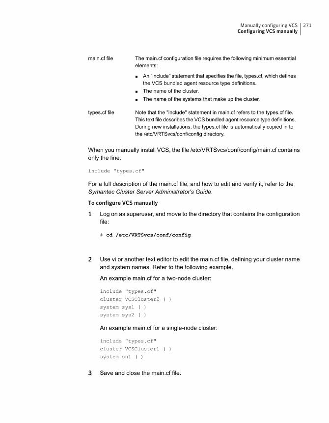
The main.cf configuration file requires the following minimum essentialelements:
■ An "include" statement that specifies the file, types.cf, which definesthe VCS bundled agent resource type definitions.
■ The name of the cluster.■ The name of the systems that make up the cluster.
main.cf file
Note that the "include" statement in main.cf refers to the types.cf file.This text file describes the VCS bundled agent resource type definitions.During new installations, the types.cf file is automatically copied in tothe /etc/VRTSvcs/conf/config directory.
types.cf file
When you manually install VCS, the file /etc/VRTSvcs/conf/config/main.cf containsonly the line:
include "types.cf"
For a full description of the main.cf file, and how to edit and verify it, refer to theSymantec Cluster Server Administrator's Guide.
To configure VCS manually
1 Log on as superuser, and move to the directory that contains the configurationfile:
# cd /etc/VRTSvcs/conf/config
2 Use vi or another text editor to edit the main.cf file, defining your cluster nameand system names. Refer to the following example.
An example main.cf for a two-node cluster:
include "types.cf"
cluster VCSCluster2 ( )
system sys1 ( )
system sys2 ( )
An example main.cf for a single-node cluster:
include "types.cf"
cluster VCSCluster1 ( )
system sn1 ( )
3 Save and close the main.cf file.
271Manually configuring VCSConfiguring VCS manually
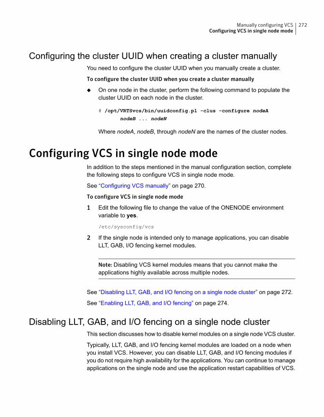
Configuring the cluster UUID when creating a cluster manuallyYou need to configure the cluster UUID when you manually create a cluster.
To configure the cluster UUID when you create a cluster manually
◆ On one node in the cluster, perform the following command to populate thecluster UUID on each node in the cluster.
# /opt/VRTSvcs/bin/uuidconfig.pl -clus -configure nodeA
nodeB ... nodeN
Where nodeA, nodeB, through nodeN are the names of the cluster nodes.
Configuring VCS in single node modeIn addition to the steps mentioned in the manual configuration section, completethe following steps to configure VCS in single node mode.
See “Configuring VCS manually” on page 270.
To configure VCS in single node mode
1 Edit the following file to change the value of the ONENODE environmentvariable to yes.
/etc/sysconfig/vcs
2 If the single node is intended only to manage applications, you can disableLLT, GAB, I/O fencing kernel modules.
Note: Disabling VCS kernel modules means that you cannot make theapplications highly available across multiple nodes.
See “Disabling LLT, GAB, and I/O fencing on a single node cluster” on page 272.
See “Enabling LLT, GAB, and I/O fencing” on page 274.
Disabling LLT, GAB, and I/O fencing on a single node clusterThis section discusses how to disable kernel modules on a single node VCS cluster.
Typically, LLT, GAB, and I/O fencing kernel modules are loaded on a node whenyou install VCS. However, you can disable LLT, GAB, and I/O fencing modules ifyou do not require high availability for the applications. You can continue to manageapplications on the single node and use the application restart capabilities of VCS.
272Manually configuring VCSConfiguring VCS in single node mode
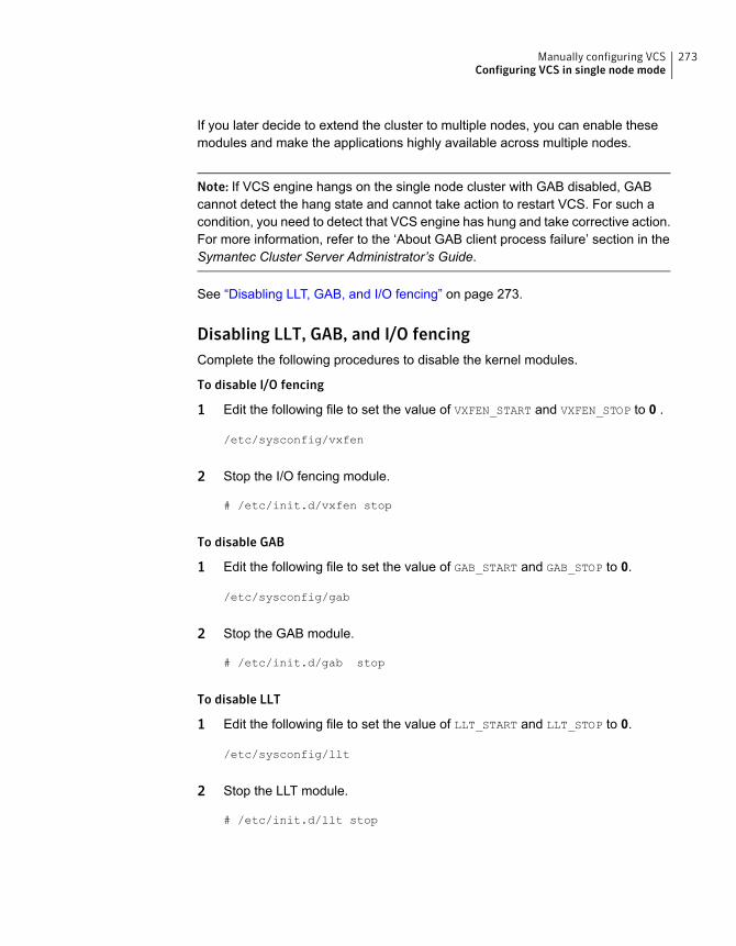
If you later decide to extend the cluster to multiple nodes, you can enable thesemodules and make the applications highly available across multiple nodes.
Note: If VCS engine hangs on the single node cluster with GAB disabled, GABcannot detect the hang state and cannot take action to restart VCS. For such acondition, you need to detect that VCS engine has hung and take corrective action.For more information, refer to the ‘About GAB client process failure’ section in theSymantec Cluster Server Administrator’s Guide.
See “Disabling LLT, GAB, and I/O fencing” on page 273.
Disabling LLT, GAB, and I/O fencingComplete the following procedures to disable the kernel modules.
To disable I/O fencing
1 Edit the following file to set the value of VXFEN_START and VXFEN_STOP to 0 .
/etc/sysconfig/vxfen
2 Stop the I/O fencing module.
# /etc/init.d/vxfen stop
To disable GAB
1 Edit the following file to set the value of GAB_START and GAB_STOP to 0.
/etc/sysconfig/gab
2 Stop the GAB module.
# /etc/init.d/gab stop
To disable LLT
1 Edit the following file to set the value of LLT_START and LLT_STOP to 0.
/etc/sysconfig/llt
2 Stop the LLT module.
# /etc/init.d/llt stop
273Manually configuring VCSConfiguring VCS in single node mode
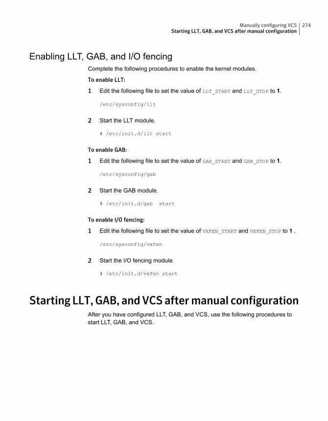
Enabling LLT, GAB, and I/O fencingComplete the following procedures to enable the kernel modules.
To enable LLT:
1 Edit the following file to set the value of LLT_START and LLT_STOP to 1.
/etc/sysconfig/llt
2 Start the LLT module.
# /etc/init.d/llt start
To enable GAB:
1 Edit the following file to set the value of GAB_START and GAB_STOP to 1.
/etc/sysconfig/gab
2 Start the GAB module.
# /etc/init.d/gab start
To enable I/O fencing:
1 Edit the following file to set the value of VXFEN_START and VXFEN_STOP to 1 .
/etc/sysconfig/vxfen
2 Start the I/O fencing module.
# /etc/init.d/vxfen start
Starting LLT,GAB, andVCSaftermanual configurationAfter you have configured LLT, GAB, and VCS, use the following procedures tostart LLT, GAB, and VCS.
274Manually configuring VCSStarting LLT, GAB, and VCS after manual configuration
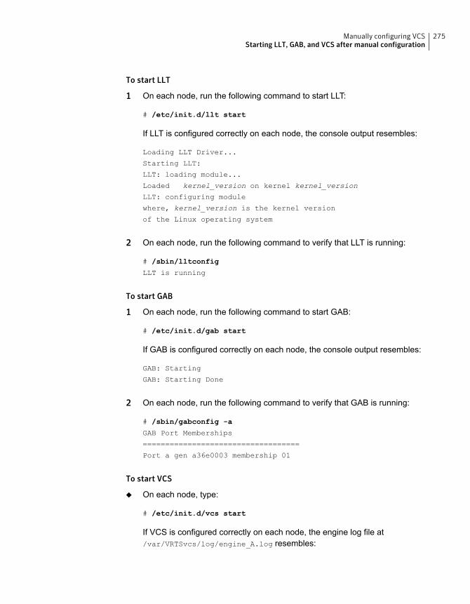
To start LLT
1 On each node, run the following command to start LLT:
# /etc/init.d/llt start
If LLT is configured correctly on each node, the console output resembles:
Loading LLT Driver...
Starting LLT:
LLT: loading module...
Loaded kernel_version on kernel kernel_version
LLT: configuring module
where, kernel_version is the kernel version
of the Linux operating system
2 On each node, run the following command to verify that LLT is running:
# /sbin/lltconfig
LLT is running
To start GAB
1 On each node, run the following command to start GAB:
# /etc/init.d/gab start
If GAB is configured correctly on each node, the console output resembles:
GAB: Starting
GAB: Starting Done
2 On each node, run the following command to verify that GAB is running:
# /sbin/gabconfig -a
GAB Port Memberships
===================================
Port a gen a36e0003 membership 01
To start VCS
◆ On each node, type:
# /etc/init.d/vcs start
If VCS is configured correctly on each node, the engine log file at/var/VRTSvcs/log/engine_A.log resembles:
275Manually configuring VCSStarting LLT, GAB, and VCS after manual configuration
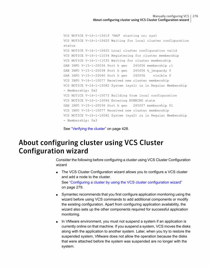
VCS NOTICE V-16-1-10619 ‘HAD’ starting on: sys1
VCS NOTICE V-16-1-10620 Waiting for local cluster configuration
status
VCS NOTICE V-16-1-10625 Local cluster configuration valid
VCS NOTICE V-16-1-11034 Registering for cluster membership
VCS NOTICE V-16-1-11035 Waiting for cluster membership
GAB INFO V-15-1-20036 Port h gen 265f06 membership ;1
GAB INFO V-15-1-20038 Port h gen 265f06 k_jeopardy 0
GAB INFO V-15-1-20040 Port h gen 265f06 visible 0
VCS INFO V-16-1-10077 Received new cluster membership
VCS NOTICE V-16-1-10082 System (sys1) is in Regular Membership
- Membership: 0x2
VCS NOTICE V-16-1-10073 Building from local configuration
VCS NOTICE V-16-1-10066 Entering RUNNING state
GAB INFO V-15-1-20036 Port h gen 265f07 membership 01
VCS INFO V-16-1-10077 Received new cluster membership
VCS NOTICE V-16-1-10082 System (sys2) is in Regular Membership
- Membership: 0x3
See “Verifying the cluster” on page 428.
About configuring cluster using VCS ClusterConfiguration wizard
Consider the following before configuring a cluster using VCS Cluster Configurationwizard
■ The VCS Cluster Configuration wizard allows you to configure a VCS clusterand add a node to the cluster.See “Configuring a cluster by using the VCS cluster configuration wizard”on page 279.
■ Symantec recommends that you first configure application monitoring using thewizard before using VCS commands to add additional components or modifythe existing configuration. Apart from configuring application availability, thewizard also sets up the other components required for successful applicationmonitoring.
■ In VMware environment, you must not suspend a system if an application iscurrently online on that machine. If you suspend a system, VCS moves the disksalong with the application to another system. Later, when you try to restore thesuspended system, VMware does not allow the operation because the disksthat were attached before the system was suspended are no longer with thesystem.
276Manually configuring VCSAbout configuring cluster using VCS Cluster Configuration wizard
Before configuring aVCScluster using theVCSClusterConfiguration wizard
Ensure that you complete the following tasks before launching the VCS ClusterConfiguration wizard to configure a VCS cluster:
■ Install Symantec Cluster Server (VCS) on the system on which you want toconfigure the VCS cluster.
■ You must have the following user privileges when you attempt to configure theVCS cluster:
■ Configure Application Monitoring (Admin) privileges when you launch thewizard from the vSphere client.
■ Admin role privileges if you launch the wizard through VOM
■ Install the application and the associated components that you want to monitoron the system.
■ If you have configured a firewall, ensure that your firewall settings allow accessto ports used by Symantec Cluster Server installer, wizards, and services.Verify that the following ports are not blocked by the firewall:
443, 5634, 14152, and 14153VMware environment
5634, 14161, 14162, 14163, and 14164 Atleast one port from 14161, 14162, 14163,and 14164 must be open.
Physical environment
■ You must not select bonded interfaces for cluster communication. A bondedinterface is a logical NIC, formed by grouping several physical NICs together.All NICs in a bond have an identical MAC address, due to which you mayexperience the following issues:
■ Single Sign On (SSO) configuration failure.
■ The wizard may fail to discover the specified network adapters.
■ The wizard may fail to discover or validate the specified system name.
■ In VMware environment, verify that the disks used by the application that youwant to monitor are attached to non-shared controllers so that they can bedetached from the system and attached to another system.
■ The host name of the system must be resolvable through the DNS server orlocally, using /etc/hosts file entries.
277Manually configuring VCSBefore configuring a VCS cluster using the VCS Cluster Configuration wizard
Launching the VCS Cluster Configuration wizardYou must launch the VCS Cluster Configuration wizard from the system where thedisk residing on the shared datastore is attached.
You can launch the VCS Cluster Configuration wizard from:
■ VMware vSphere ClientSee Launching the VCS Cluster Configuration wizard from VMware vSphereClient.
■ A browser windowSee Launching the VCS Cluster Configuration wizard from a browser window.
Launching theVCSCluster Configurationwizard fromVMwarevSphere ClientTo launch the wizard from the VMware vSphere Client:
1 Launch the VMware vSphere Client and connect to the VMware vCenter Serverthat hosts the virtual machine.
2 From the vSphere Client’s Inventory view in the left pane, select the virtualmachine where you want to configure the VCS cluster.
3 Select the Symantec High Availability tab.
The tab displays various menus based on the what is configured on the system.The menu options launch the appropriate wizard panel based on the tasks thatyou choose to perform.
Launching theVCSClusterConfigurationwizard fromabrowserwindowYou can launch the VCS Cluster Configuration wizard from the Symantec HighAvailability view.
1 Open a browser window and enter the following URL:
https://<IP_or_HostName>:5634/vcs/admin/application_health.html
where <IP_or_HostName> is the IP address or host name of the system onwhich you want to configure the cluster.
2 Click the Configure cluster link on the Symantec High Availability view pageto launch the wizard.
Note:At various stages of cluster configuration, the Symantec High Availability viewoffers different configuration options. These options launch appropriate wizardpanels based on the tasks that you choose to perform.
278Manually configuring VCSLaunching the VCS Cluster Configuration wizard
See “Configuring a cluster by using the VCS cluster configuration wizard”on page 279.
See “Adding a system to a VCS cluster” on page 283.
Refer to theAdministering applicationmonitoring from the Symantec High Availabilityview section in Symantec Cluster Server Administrator's Guide for more informationon the configurations possible from the Symantec High Availability view.
Configuring a cluster by using the VCS clusterconfiguration wizard
Perform the following steps to configure a Symantec Cluster Server (VCS) clusterby using the VCS Cluster Configuration wizard.
To configure a VCS cluster
1 Access the Symantec High Availability view (for any system belonging therequired cluster).
See “Launching the VCS Cluster Configuration wizard” on page 278.
2 Review the information on the Welcome panel and click Next.
The Configuration Inputs panel appears.
The local system is by default selected as a cluster system.
279Manually configuring VCSConfiguring a cluster by using the VCS cluster configuration wizard
3 If you do not want to add more systems to the cluster, skip this step. You canadd systems later using the same wizard.
To add a system to the cluster, click Add System.
In the Add System dialog box, specify the following details for the system thatyou want to add to the VCS cluster and click OK.
Specify the name or IP address of thesystem that you want to add to the VCScluster.
System Name or IP address
Specify the user account for the system.
Typically, this is the root user. The rootuser should have the necessary privileges.
User name
Specify the password for the user accountyou specified.
Password
Select this check box to use the specifieduser account on all the cluster systems thathave the same user name and password.
Use the specified user account on allsystems
4 On the Configuration Inputs panel, do one of the following actions:
■ To add another system to the cluster, click Add System and repeat step 3.
■ To modify the specified User name or Password for a cluster system, usethe edit icon.
■ Click Next
5 If you do not want to modify the security settings for the cluster, click Next, andproceed to step 7.
By default, the wizard configures single sign-on for secure clustercommunication. If you want to modify the security settings for the cluster, clickAdvanced Settings.
280Manually configuring VCSConfiguring a cluster by using the VCS cluster configuration wizard
6 In the Advanced settings dialog box, specify the following details and click OK.
Select to configure single sign-on usingVCS Authentication Service for clustercommunication.
This option is enabled by default.
Use Single Sign-on
Select to configure a user withadministrative privileges to the cluster.
Specify the username and password andclick OK.
Use VCS user privileges
7 On the Network Details panel, select the type of network protocol to configurethe VCS cluster network links (Low Latency Transport or LLT module), andthen specify the adapters for network communication.
The wizard configures the VCS cluster communication links using theseadapters. You must select a minimum of two adapters per cluster system.
Note: By default, the LLT links are configured over Ethernet.
Select Use MAC address for cluster communication (LLT over Ethernet)or select Use IP address for cluster communication (LLT over UDP), andspecify the following details for each cluster system.
■ To configure LLT over Ethernet, select the adapter for each networkcommunication link. You must select a different network adapter for eachcommunication link.
■ To configure LLT over UDP, select the type of IP protocol (IPv4 or IPv6),and then specify the required details for each communication link.
Select a network adapter for thecommunication links.
You must select a different networkadapter for each communication link.
Network Adapter
Displays the IP address.IP Address
281Manually configuring VCSConfiguring a cluster by using the VCS cluster configuration wizard
Specify a unique port number for eachlink.
For IPv4 and IPv6, the port range is from49152 to 65535.
A specified port for a link is used for allthe cluster systems on that link.
Port
Displays the subnet mask details.Subnet mask (IPv4)
Displays the prefix details.Prefix (IPv6)
By default, one of the links is configured as a low-priority link on a public networkinterface. The second link is configured as a high-priority link.
To change a high-priority link to a low-priority link, click Modify. In the Modifylow-priority link dialog box, select the link and click OK.
Note: Symantec recommends that you configure one of the links on a publicnetwork interface. You can assign the link on the public network interface asa low-priority link for minimal VCS cluster communication over the link.
8 On the Configuration Summary panel, specify a cluster name and unique clusterID and then click Validate.
Note: If multiple clusters exist in your network, the wizard validates if thespecified cluster ID is a unique cluster ID among all clusters accessible fromthe current system. Among clusters that are not accessible from the currentsystem, you must ensure that the cluster ID you specified is unique
9 Review the VCS Cluster Configuration Details and then click Next to proceedwith the configuration
10 On the Implementation panel, the wizard creates the VCS cluster.
The wizard displays the status of the configuration task. After the configurationis complete, click Next.
If the configuration task fails, click Diagnostic information to check the detailsof the failure. Rectify the cause of the failure and run the wizard again toconfigure the VCS cluster.
11 On the Finish panel, click Finish to complete the wizard workflow.
This completes the VCS cluster configuration.
282Manually configuring VCSConfiguring a cluster by using the VCS cluster configuration wizard
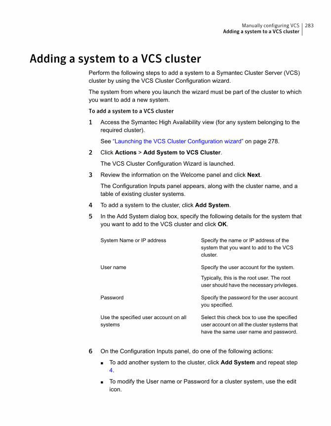
Adding a system to a VCS clusterPerform the following steps to add a system to a Symantec Cluster Server (VCS)cluster by using the VCS Cluster Configuration wizard.
The system from where you launch the wizard must be part of the cluster to whichyou want to add a new system.
To add a system to a VCS cluster
1 Access the Symantec High Availability view (for any system belonging to therequired cluster).
See “Launching the VCS Cluster Configuration wizard” on page 278.
2 Click Actions > Add System to VCS Cluster.
The VCS Cluster Configuration Wizard is launched.
3 Review the information on the Welcome panel and click Next.
The Configuration Inputs panel appears, along with the cluster name, and atable of existing cluster systems.
4 To add a system to the cluster, click Add System.
5 In the Add System dialog box, specify the following details for the system thatyou want to add to the VCS cluster and click OK.
Specify the name or IP address of thesystem that you want to add to the VCScluster.
System Name or IP address
Specify the user account for the system.
Typically, this is the root user. The rootuser should have the necessary privileges.
User name
Specify the password for the user accountyou specified.
Password
Select this check box to use the specifieduser account on all the cluster systems thathave the same user name and password.
Use the specified user account on allsystems
6 On the Configuration Inputs panel, do one of the following actions:
■ To add another system to the cluster, click Add System and repeat step4.
■ To modify the User name or Password for a cluster system, use the editicon.
283Manually configuring VCSAdding a system to a VCS cluster
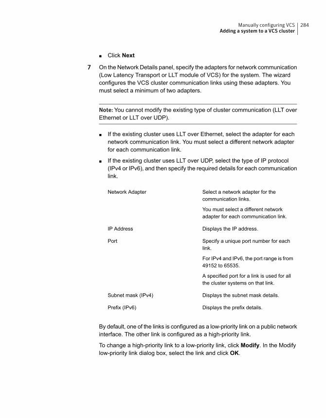
■ Click Next
7 On the Network Details panel, specify the adapters for network communication(Low Latency Transport or LLT module of VCS) for the system. The wizardconfigures the VCS cluster communication links using these adapters. Youmust select a minimum of two adapters.
Note: You cannot modify the existing type of cluster communication (LLT overEthernet or LLT over UDP).
■ If the existing cluster uses LLT over Ethernet, select the adapter for eachnetwork communication link. You must select a different network adapterfor each communication link.
■ If the existing cluster uses LLT over UDP, select the type of IP protocol(IPv4 or IPv6), and then specify the required details for each communicationlink.
Select a network adapter for thecommunication links.
You must select a different networkadapter for each communication link.
Network Adapter
Displays the IP address.IP Address
Specify a unique port number for eachlink.
For IPv4 and IPv6, the port range is from49152 to 65535.
A specified port for a link is used for allthe cluster systems on that link.
Port
Displays the subnet mask details.Subnet mask (IPv4)
Displays the prefix details.Prefix (IPv6)
By default, one of the links is configured as a low-priority link on a public networkinterface. The other link is configured as a high-priority link.
To change a high-priority link to a low-priority link, click Modify. In the Modifylow-priority link dialog box, select the link and click OK.
284Manually configuring VCSAdding a system to a VCS cluster
Note: Symantec recommends that you configure one of the links on a publicnetwork interface. You can assign the link on the public network interface asa low-priority link for minimal VCS cluster communication over the link.
8 On the Configuration Summary panel, review the VCS Cluster ConfigurationDetails.
9 On the Implementation panel, the wizard creates the VCS cluster.
The wizard displays the status of the configuration task. After the configurationis complete, click Next.
If the configuration task fails, click Diagnostic information to check the detailsof the failure. Rectify the cause of the failure and run the wizard again to addthe required system to the VCS cluster.
10 On the Finish panel, click Finish to complete the wizard workflow.
Modifying the VCS configurationAfter the successful installation of VCS, you can modify the configuration of VCSusing several methods. You can dynamically modify the configuration from thecommand line, Veritas Operations Manager, or the Cluster Manager (Java Console).For information on management tools, refer to the Symantec Cluster ServerAdministrator's Guide.
You can also edit the main.cf file directly. For information on the structure of themain.cf file, refer to the Symantec Cluster Server Administrator's Guide.
Configuring the ClusterService groupWhen you have installed VCS, and verified that LLT, GAB, and VCS work, you cancreate a service group to include the optional features. These features include theVCS notification components and the Global Cluster option. If you manually addedVCS to your cluster systems, you must manually create the ClusterService group.You can refer to the configuration examples of a system with a ClusterServicegroup. See the Symantec Cluster Server Administrator's Guide for more information.
See “Sample main.cf file for VCS clusters” on page 506.
285Manually configuring VCSModifying the VCS configuration
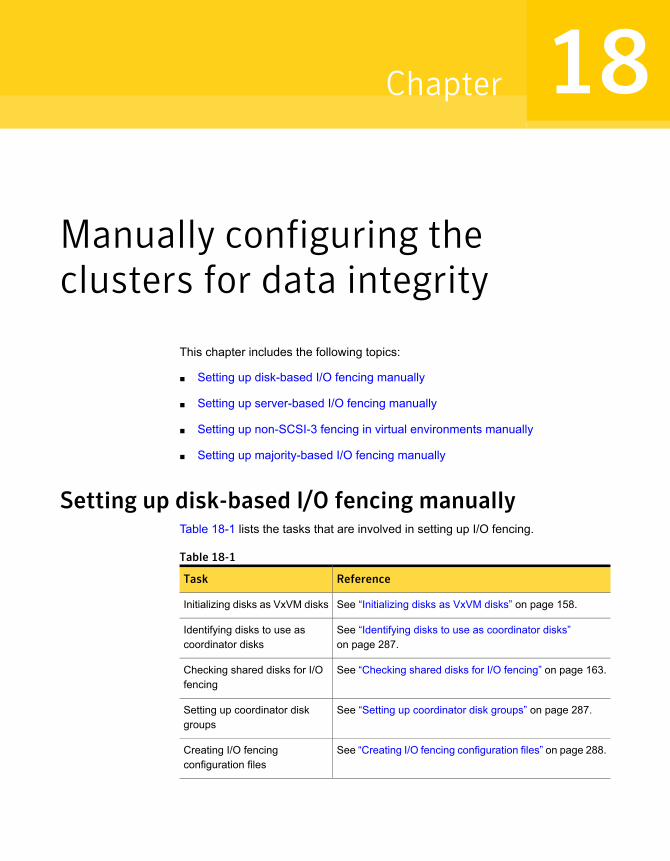
Manually configuring theclusters for data integrity
This chapter includes the following topics:
■ Setting up disk-based I/O fencing manually
■ Setting up server-based I/O fencing manually
■ Setting up non-SCSI-3 fencing in virtual environments manually
■ Setting up majority-based I/O fencing manually
Setting up disk-based I/O fencing manuallyTable 18-1 lists the tasks that are involved in setting up I/O fencing.
Table 18-1
ReferenceTask
See “Initializing disks as VxVM disks” on page 158.Initializing disks as VxVM disks
See “Identifying disks to use as coordinator disks”on page 287.
Identifying disks to use ascoordinator disks
See “Checking shared disks for I/O fencing” on page 163.Checking shared disks for I/Ofencing
See “Setting up coordinator disk groups” on page 287.Setting up coordinator diskgroups
See “Creating I/O fencing configuration files” on page 288.Creating I/O fencingconfiguration files
18Chapter
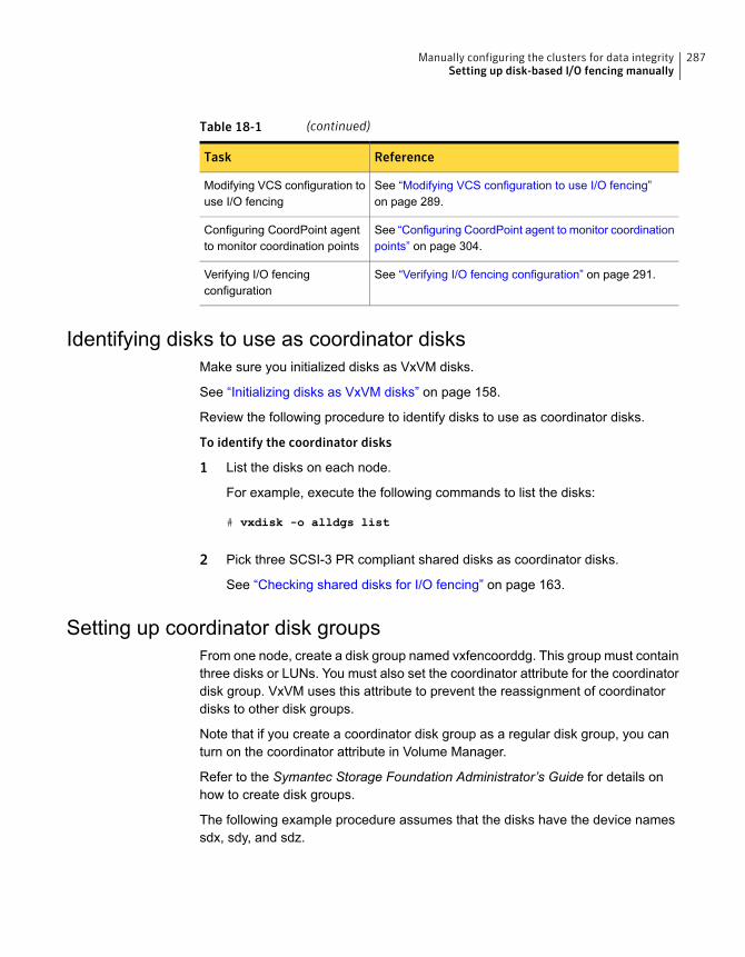
Table 18-1 (continued)
ReferenceTask
See “Modifying VCS configuration to use I/O fencing”on page 289.
Modifying VCS configuration touse I/O fencing
See “Configuring CoordPoint agent to monitor coordinationpoints” on page 304.
Configuring CoordPoint agentto monitor coordination points
See “Verifying I/O fencing configuration” on page 291.Verifying I/O fencingconfiguration
Identifying disks to use as coordinator disksMake sure you initialized disks as VxVM disks.
See “Initializing disks as VxVM disks” on page 158.
Review the following procedure to identify disks to use as coordinator disks.
To identify the coordinator disks
1 List the disks on each node.
For example, execute the following commands to list the disks:
# vxdisk -o alldgs list
2 Pick three SCSI-3 PR compliant shared disks as coordinator disks.
See “Checking shared disks for I/O fencing” on page 163.
Setting up coordinator disk groupsFrom one node, create a disk group named vxfencoorddg. This group must containthree disks or LUNs. You must also set the coordinator attribute for the coordinatordisk group. VxVM uses this attribute to prevent the reassignment of coordinatordisks to other disk groups.
Note that if you create a coordinator disk group as a regular disk group, you canturn on the coordinator attribute in Volume Manager.
Refer to the Symantec Storage Foundation Administrator’s Guide for details onhow to create disk groups.
The following example procedure assumes that the disks have the device namessdx, sdy, and sdz.
287Manually configuring the clusters for data integritySetting up disk-based I/O fencing manually
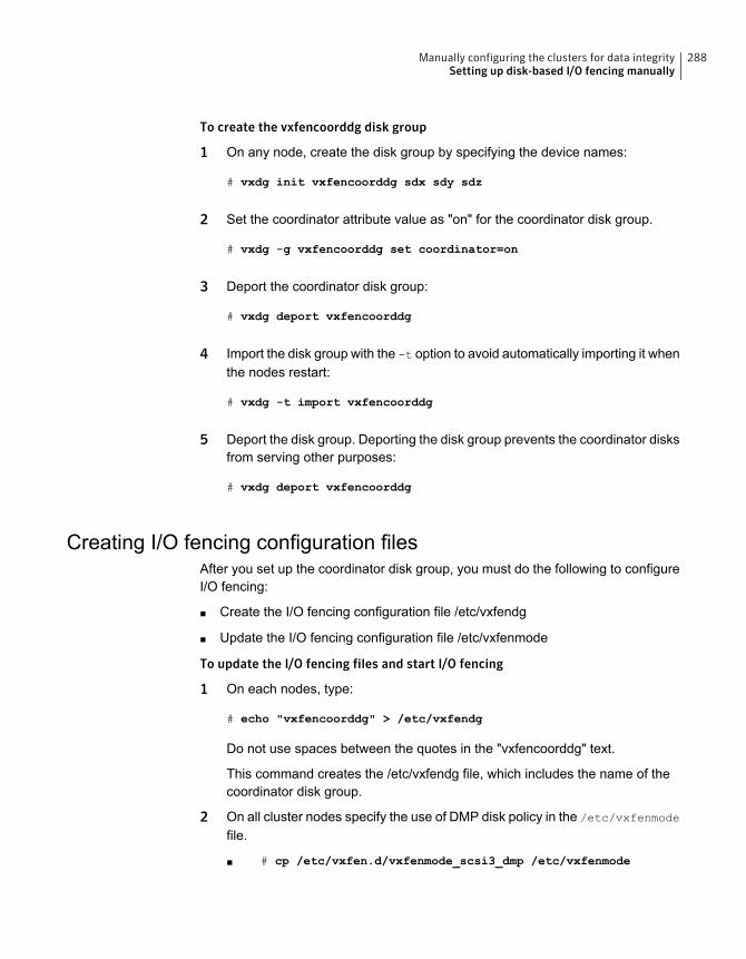
To create the vxfencoorddg disk group
1 On any node, create the disk group by specifying the device names:
# vxdg init vxfencoorddg sdx sdy sdz
2 Set the coordinator attribute value as "on" for the coordinator disk group.
# vxdg -g vxfencoorddg set coordinator=on
3 Deport the coordinator disk group:
# vxdg deport vxfencoorddg
4 Import the disk group with the -t option to avoid automatically importing it whenthe nodes restart:
# vxdg -t import vxfencoorddg
5 Deport the disk group. Deporting the disk group prevents the coordinator disksfrom serving other purposes:
# vxdg deport vxfencoorddg
Creating I/O fencing configuration filesAfter you set up the coordinator disk group, you must do the following to configureI/O fencing:
■ Create the I/O fencing configuration file /etc/vxfendg
■ Update the I/O fencing configuration file /etc/vxfenmode
To update the I/O fencing files and start I/O fencing
1 On each nodes, type:
# echo "vxfencoorddg" > /etc/vxfendg
Do not use spaces between the quotes in the "vxfencoorddg" text.
This command creates the /etc/vxfendg file, which includes the name of thecoordinator disk group.
2 On all cluster nodes specify the use of DMP disk policy in the /etc/vxfenmode
file.
■ # cp /etc/vxfen.d/vxfenmode_scsi3_dmp /etc/vxfenmode
288Manually configuring the clusters for data integritySetting up disk-based I/O fencing manually
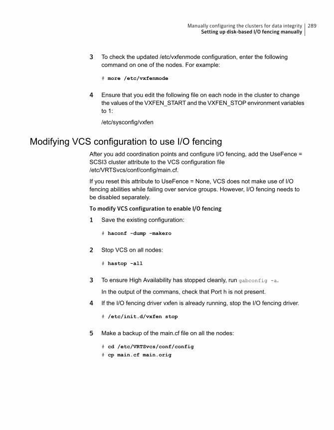
3 To check the updated /etc/vxfenmode configuration, enter the followingcommand on one of the nodes. For example:
# more /etc/vxfenmode
4 Ensure that you edit the following file on each node in the cluster to changethe values of the VXFEN_START and the VXFEN_STOP environment variablesto 1:
/etc/sysconfig/vxfen
Modifying VCS configuration to use I/O fencingAfter you add coordination points and configure I/O fencing, add the UseFence =SCSI3 cluster attribute to the VCS configuration file/etc/VRTSvcs/conf/config/main.cf.
If you reset this attribute to UseFence = None, VCS does not make use of I/Ofencing abilities while failing over service groups. However, I/O fencing needs tobe disabled separately.
To modify VCS configuration to enable I/O fencing
1 Save the existing configuration:
# haconf -dump -makero
2 Stop VCS on all nodes:
# hastop -all
3 To ensure High Availability has stopped cleanly, run gabconfig -a.
In the output of the commans, check that Port h is not present.
4 If the I/O fencing driver vxfen is already running, stop the I/O fencing driver.
# /etc/init.d/vxfen stop
5 Make a backup of the main.cf file on all the nodes:
# cd /etc/VRTSvcs/conf/config
# cp main.cf main.orig
289Manually configuring the clusters for data integritySetting up disk-based I/O fencing manually
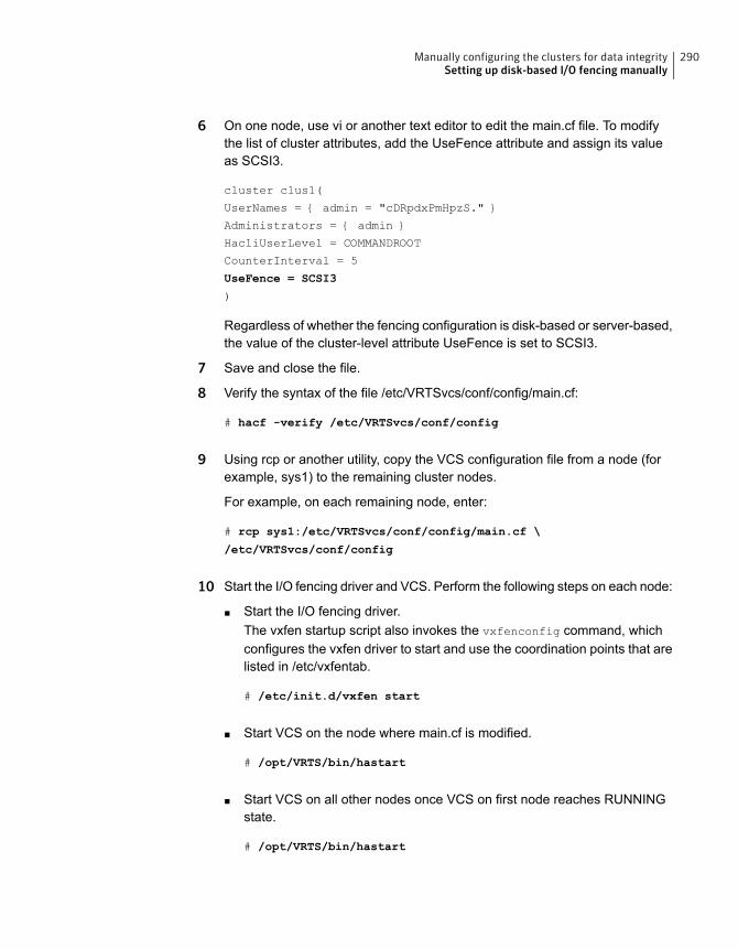
6 On one node, use vi or another text editor to edit the main.cf file. To modifythe list of cluster attributes, add the UseFence attribute and assign its valueas SCSI3.
cluster clus1(
UserNames = { admin = "cDRpdxPmHpzS." }
Administrators = { admin }
HacliUserLevel = COMMANDROOT
CounterInterval = 5
UseFence = SCSI3
)
Regardless of whether the fencing configuration is disk-based or server-based,the value of the cluster-level attribute UseFence is set to SCSI3.
7 Save and close the file.
8 Verify the syntax of the file /etc/VRTSvcs/conf/config/main.cf:
# hacf -verify /etc/VRTSvcs/conf/config
9 Using rcp or another utility, copy the VCS configuration file from a node (forexample, sys1) to the remaining cluster nodes.
For example, on each remaining node, enter:
# rcp sys1:/etc/VRTSvcs/conf/config/main.cf \
/etc/VRTSvcs/conf/config
10 Start the I/O fencing driver and VCS. Perform the following steps on each node:
■ Start the I/O fencing driver.The vxfen startup script also invokes the vxfenconfig command, whichconfigures the vxfen driver to start and use the coordination points that arelisted in /etc/vxfentab.
# /etc/init.d/vxfen start
■ Start VCS on the node where main.cf is modified.
# /opt/VRTS/bin/hastart
■ Start VCS on all other nodes once VCS on first node reaches RUNNINGstate.
# /opt/VRTS/bin/hastart
290Manually configuring the clusters for data integritySetting up disk-based I/O fencing manually
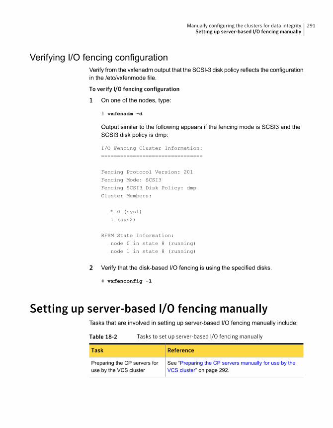
Verifying I/O fencing configurationVerify from the vxfenadm output that the SCSI-3 disk policy reflects the configurationin the /etc/vxfenmode file.
To verify I/O fencing configuration
1 On one of the nodes, type:
# vxfenadm -d
Output similar to the following appears if the fencing mode is SCSI3 and theSCSI3 disk policy is dmp:
I/O Fencing Cluster Information:
================================
Fencing Protocol Version: 201
Fencing Mode: SCSI3
Fencing SCSI3 Disk Policy: dmp
Cluster Members:
* 0 (sys1)
1 (sys2)
RFSM State Information:
node 0 in state 8 (running)
node 1 in state 8 (running)
2 Verify that the disk-based I/O fencing is using the specified disks.
# vxfenconfig -l
Setting up server-based I/O fencing manuallyTasks that are involved in setting up server-based I/O fencing manually include:
Table 18-2 Tasks to set up server-based I/O fencing manually
ReferenceTask
See “Preparing the CP servers manually for use by theVCS cluster” on page 292.
Preparing the CP servers foruse by the VCS cluster
291Manually configuring the clusters for data integritySetting up server-based I/O fencing manually
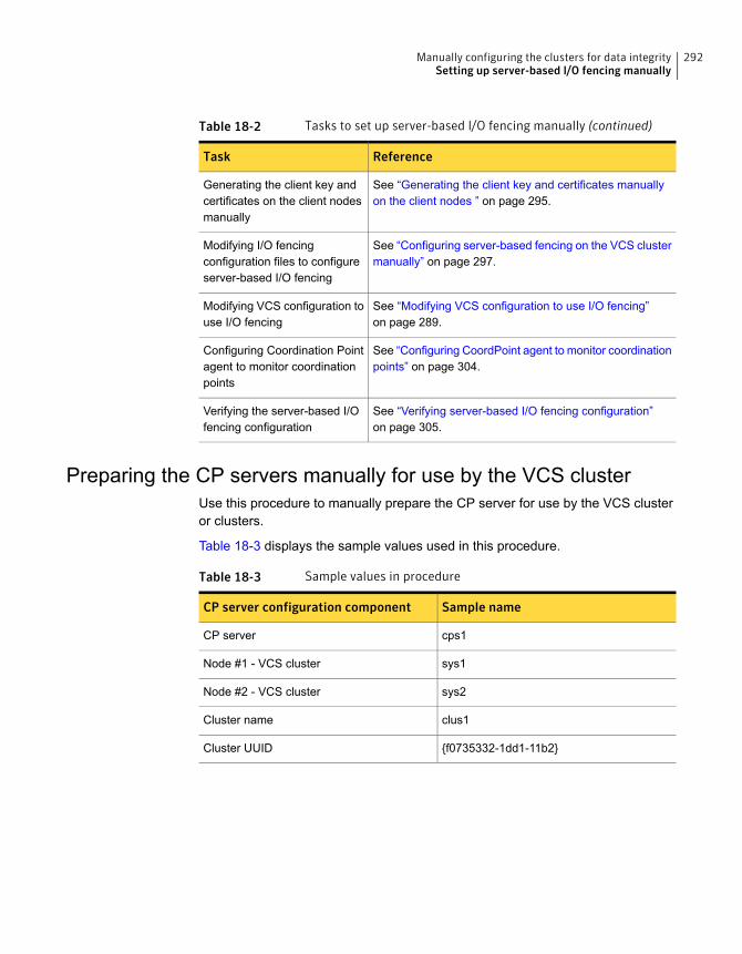
Table 18-2 Tasks to set up server-based I/O fencing manually (continued)
ReferenceTask
See “Generating the client key and certificates manuallyon the client nodes ” on page 295.
Generating the client key andcertificates on the client nodesmanually
See “Configuring server-based fencing on the VCS clustermanually” on page 297.
Modifying I/O fencingconfiguration files to configureserver-based I/O fencing
See “Modifying VCS configuration to use I/O fencing”on page 289.
Modifying VCS configuration touse I/O fencing
See “Configuring CoordPoint agent to monitor coordinationpoints” on page 304.
Configuring Coordination Pointagent to monitor coordinationpoints
See “Verifying server-based I/O fencing configuration”on page 305.
Verifying the server-based I/Ofencing configuration
Preparing the CP servers manually for use by the VCS clusterUse this procedure to manually prepare the CP server for use by the VCS clusteror clusters.
Table 18-3 displays the sample values used in this procedure.
Table 18-3 Sample values in procedure
Sample nameCP server configuration component
cps1CP server
sys1Node #1 - VCS cluster
sys2Node #2 - VCS cluster
clus1Cluster name
{f0735332-1dd1-11b2}Cluster UUID
292Manually configuring the clusters for data integritySetting up server-based I/O fencing manually

To manually configure CP servers for use by the VCS cluster
1 Determine the cluster name and uuid on the VCS cluster.
For example, issue the following commands on one of the VCS cluster nodes(sys1):
# grep cluster /etc/VRTSvcs/conf/config/main.cf
cluster clus1
# cat /etc/vx/.uuids/clusuuid
{f0735332-1dd1-11b2-bb31-00306eea460a}
2 Use the cpsadm command to check whether the VCS cluster and nodes arepresent in the CP server.
For example:
# cpsadm -s cps1.symantecexample.com -a list_nodes
ClusName UUID Hostname(Node ID) Registered
clus1 {f0735332-1dd1-11b2-bb31-00306eea460a} sys1(0) 0
clus1 {f0735332-1dd1-11b2-bb31-00306eea460a} sys2(1) 0
If the output does not show the cluster and nodes, then add them as describedin the next step.
For detailed information about the cpsadm command, see the Symantec ClusterServer Administrator's Guide.
293Manually configuring the clusters for data integritySetting up server-based I/O fencing manually
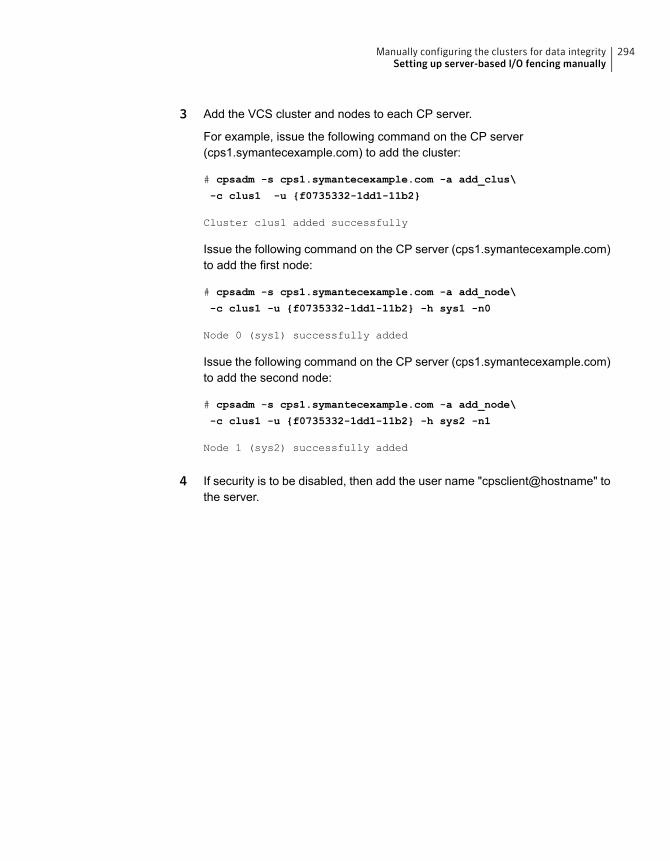
3 Add the VCS cluster and nodes to each CP server.
For example, issue the following command on the CP server(cps1.symantecexample.com) to add the cluster:
# cpsadm -s cps1.symantecexample.com -a add_clus\
-c clus1 -u {f0735332-1dd1-11b2}
Cluster clus1 added successfully
Issue the following command on the CP server (cps1.symantecexample.com)to add the first node:
# cpsadm -s cps1.symantecexample.com -a add_node\
-c clus1 -u {f0735332-1dd1-11b2} -h sys1 -n0
Node 0 (sys1) successfully added
Issue the following command on the CP server (cps1.symantecexample.com)to add the second node:
# cpsadm -s cps1.symantecexample.com -a add_node\
-c clus1 -u {f0735332-1dd1-11b2} -h sys2 -n1
Node 1 (sys2) successfully added
4 If security is to be disabled, then add the user name "cpsclient@hostname" tothe server.
294Manually configuring the clusters for data integritySetting up server-based I/O fencing manually
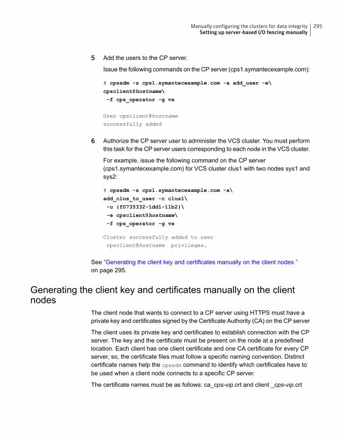
5 Add the users to the CP server.
Issue the following commands on the CP server (cps1.symantecexample.com):
# cpsadm -s cps1.symantecexample.com -a add_user -e\
cpsclient@hostname\
-f cps_operator -g vx
User cpsclient@hostname
successfully added
6 Authorize the CP server user to administer the VCS cluster. You must performthis task for the CP server users corresponding to each node in the VCS cluster.
For example, issue the following command on the CP server(cps1.symantecexample.com) for VCS cluster clus1 with two nodes sys1 andsys2:
# cpsadm -s cps1.symantecexample.com -a\
add_clus_to_user -c clus1\
-u {f0735332-1dd1-11b2}\
-e cpsclient@hostname\
-f cps_operator -g vx
Cluster successfully added to user
cpsclient@hostname privileges.
See “Generating the client key and certificates manually on the client nodes ”on page 295.
Generating the client key and certificates manually on the clientnodes
The client node that wants to connect to a CP server using HTTPS must have aprivate key and certificates signed by the Certificate Authority (CA) on the CP server
The client uses its private key and certificates to establish connection with the CPserver. The key and the certificate must be present on the node at a predefinedlocation. Each client has one client certificate and one CA certificate for every CPserver, so, the certificate files must follow a specific naming convention. Distinctcertificate names help the cpsadm command to identify which certificates have tobe used when a client node connects to a specific CP server.
The certificate names must be as follows: ca_cps-vip.crt and client _cps-vip.crt
295Manually configuring the clusters for data integritySetting up server-based I/O fencing manually
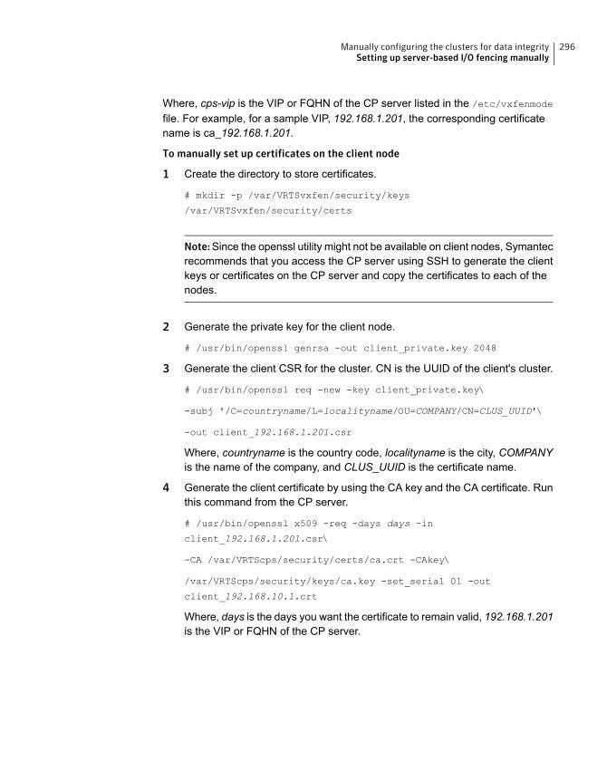
Where, cps-vip is the VIP or FQHN of the CP server listed in the /etc/vxfenmode
file. For example, for a sample VIP, 192.168.1.201, the corresponding certificatename is ca_192.168.1.201.
To manually set up certificates on the client node
1 Create the directory to store certificates.
# mkdir -p /var/VRTSvxfen/security/keys
/var/VRTSvxfen/security/certs
Note:Since the openssl utility might not be available on client nodes, Symantecrecommends that you access the CP server using SSH to generate the clientkeys or certificates on the CP server and copy the certificates to each of thenodes.
2 Generate the private key for the client node.
# /usr/bin/openssl genrsa -out client_private.key 2048
3 Generate the client CSR for the cluster. CN is the UUID of the client's cluster.
# /usr/bin/openssl req -new -key client_private.key\
-subj '/C=countryname/L=localityname/OU=COMPANY/CN=CLUS_UUID'\
-out client_192.168.1.201.csr
Where, countryname is the country code, localityname is the city, COMPANYis the name of the company, and CLUS_UUID is the certificate name.
4 Generate the client certificate by using the CA key and the CA certificate. Runthis command from the CP server.
# /usr/bin/openssl x509 -req -days days -in
client_192.168.1.201.csr\
-CA /var/VRTScps/security/certs/ca.crt -CAkey\
/var/VRTScps/security/keys/ca.key -set_serial 01 -out
client_192.168.10.1.crt
Where, days is the days you want the certificate to remain valid, 192.168.1.201is the VIP or FQHN of the CP server.
296Manually configuring the clusters for data integritySetting up server-based I/O fencing manually
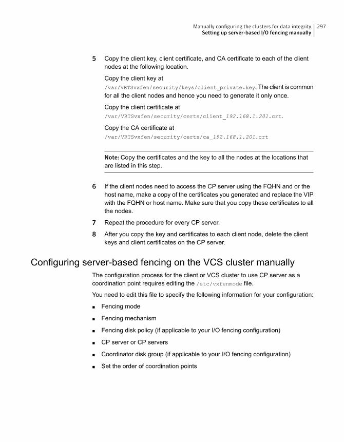
5 Copy the client key, client certificate, and CA certificate to each of the clientnodes at the following location.
Copy the client key at/var/VRTSvxfen/security/keys/client_private.key. The client is commonfor all the client nodes and hence you need to generate it only once.
Copy the client certificate at/var/VRTSvxfen/security/certs/client_192.168.1.201.crt.
Copy the CA certificate at/var/VRTSvxfen/security/certs/ca_192.168.1.201.crt
Note: Copy the certificates and the key to all the nodes at the locations thatare listed in this step.
6 If the client nodes need to access the CP server using the FQHN and or thehost name, make a copy of the certificates you generated and replace the VIPwith the FQHN or host name. Make sure that you copy these certificates to allthe nodes.
7 Repeat the procedure for every CP server.
8 After you copy the key and certificates to each client node, delete the clientkeys and client certificates on the CP server.
Configuring server-based fencing on the VCS cluster manuallyThe configuration process for the client or VCS cluster to use CP server as acoordination point requires editing the /etc/vxfenmode file.
You need to edit this file to specify the following information for your configuration:
■ Fencing mode
■ Fencing mechanism
■ Fencing disk policy (if applicable to your I/O fencing configuration)
■ CP server or CP servers
■ Coordinator disk group (if applicable to your I/O fencing configuration)
■ Set the order of coordination points
297Manually configuring the clusters for data integritySetting up server-based I/O fencing manually
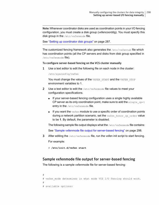
Note:Whenever coordinator disks are used as coordination points in your I/O fencingconfiguration, you must create a disk group (vxfencoorddg). You must specify thisdisk group in the /etc/vxfenmode file.
See “Setting up coordinator disk groups” on page 287.
The customized fencing framework also generates the /etc/vxfentab file whichhas coordination points (all the CP servers and disks from disk group specified in/etc/vxfenmode file).
To configure server-based fencing on the VCS cluster manually
1 Use a text editor to edit the following file on each node in the cluster:
/etc/sysconfig/vxfen
You must change the values of the VXFEN_START and the VXFEN_STOP
environment variables to 1.
2 Use a text editor to edit the /etc/vxfenmode file values to meet yourconfiguration specifications.
■ If your server-based fencing configuration uses a single highly availableCP server as its only coordination point, make sure to add the single_cp=1
entry in the /etc/vxfenmode file.
■ If you want the vxfen module to use a specific order of coordination pointsduring a network partition scenario, set the vxfen_honor_cp_order valueto be 1. By default, the parameter is disabled.
The following sample file output displays what the /etc/vxfenmode file contains:
See “Sample vxfenmode file output for server-based fencing” on page 298.
3 After editing the /etc/vxfenmode file, run the vxfen init script to start fencing.
For example:
# /etc/init.d/vxfen start
Sample vxfenmode file output for server-based fencingThe following is a sample vxfenmode file for server-based fencing:
#
# vxfen_mode determines in what mode VCS I/O Fencing should work.
#
# available options:
298Manually configuring the clusters for data integritySetting up server-based I/O fencing manually

# scsi3 - use scsi3 persistent reservation disks
# customized - use script based customized fencing
# disabled - run the driver but don't do any actual fencing
#
vxfen_mode=customized
# vxfen_mechanism determines the mechanism for customized I/O
# fencing that should be used.
#
# available options:
# cps - use a coordination point server with optional script
# controlled scsi3 disks
#
vxfen_mechanism=cps
#
# scsi3_disk_policy determines the way in which I/O fencing
# communicates with the coordination disks. This field is
# required only if customized coordinator disks are being used.
#
# available options:
# dmp - use dynamic multipathing
#
scsi3_disk_policy=dmp
#
# security parameter is deprecated release 6.1 onwards
# since communication with CP server will always happen
# over HTTPS which is inherently secure. In pre-6.1 releases,
# it was used to configure secure communication to the
# cp server using VxAT (Veritas Authentication Service)
# available options:
# 0 - don't use Veritas Authentication Service for cp server
# communication
# 1 - use Veritas Authentication Service for cp server
# communication
security=1
#
# vxfen_honor_cp_order determines the order in which vxfen
# should use the coordination points specified in this file.
#
# available options:
299Manually configuring the clusters for data integritySetting up server-based I/O fencing manually

# 0 - vxfen uses a sorted list of coordination points specified
# in this file,
# the order in which coordination points are specified does not matter.
# (default)
# 1 - vxfen uses the coordination points in the same order they are
# specified in this file
# Specify 3 or more odd number of coordination points in this file,
# each one in its own line. They can be all-CP servers,
# all-SCSI-3 compliant coordinator disks, or a combination of
# CP servers and SCSI-3 compliant coordinator disks.
# Please ensure that the CP server coordination points
# are numbered sequentially and in the same order
# on all the cluster nodes.
#
# Coordination Point Server(CPS) is specified as follows:
#
# cps<number>=[<vip/vhn>]:<port>
#
# If a CPS supports multiple virtual IPs or virtual hostnames
# over different subnets, all of the IPs/names can be specified
# in a comma separated list as follows:
#
# cps<number>=[<vip_1/vhn_1>]:<port_1>,[<vip_2/vhn_2>]:<port_2>,
...,[<vip_n/vhn_n>]:<port_n>
#
# Where,
# <number>
# is the serial number of the CPS as a coordination point; must
# start with 1.
# <vip>
# is the virtual IP address of the CPS, must be specified in
# square brackets ("[]").
# <vhn>
# is the virtual hostname of the CPS, must be specified in square
# brackets ("[]").
# <port>
# is the port number bound to a particular <vip/vhn> of the CPS.
# It is optional to specify a <port>. However, if specified, it
# must follow a colon (":") after <vip/vhn>. If not specified, the
# colon (":") must not exist after <vip/vhn>.
#
# For all the <vip/vhn>s which do not have a specified <port>,
300Manually configuring the clusters for data integritySetting up server-based I/O fencing manually
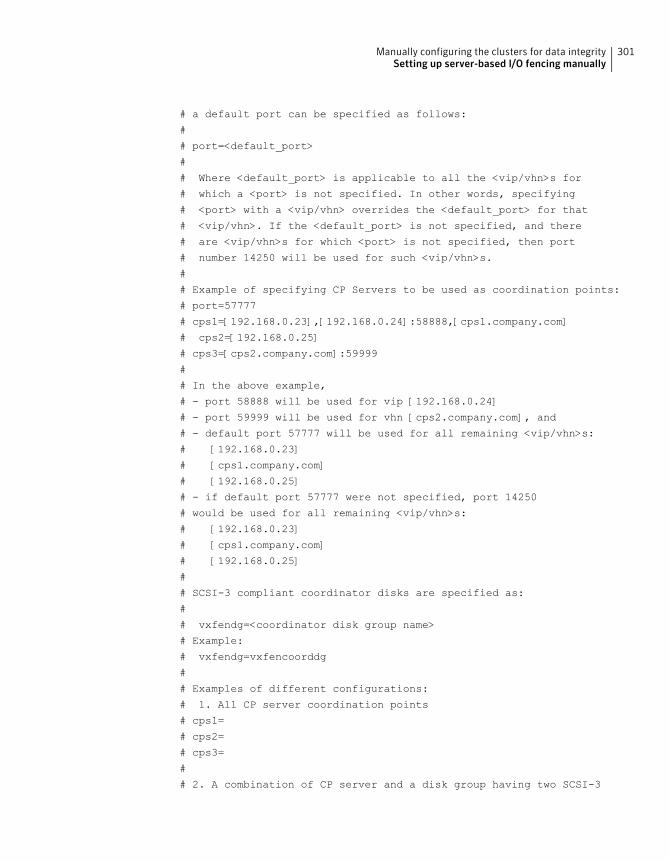
# a default port can be specified as follows:
#
# port=<default_port>
#
# Where <default_port> is applicable to all the <vip/vhn>s for
# which a <port> is not specified. In other words, specifying
# <port> with a <vip/vhn> overrides the <default_port> for that
# <vip/vhn>. If the <default_port> is not specified, and there
# are <vip/vhn>s for which <port> is not specified, then port
# number 14250 will be used for such <vip/vhn>s.
#
# Example of specifying CP Servers to be used as coordination points:
# port=57777
# cps1=[192.168.0.23],[192.168.0.24]:58888,[cps1.company.com]
# cps2=[192.168.0.25]
# cps3=[cps2.company.com]:59999
#
# In the above example,
# - port 58888 will be used for vip [192.168.0.24]
# - port 59999 will be used for vhn [cps2.company.com], and
# - default port 57777 will be used for all remaining <vip/vhn>s:
# [192.168.0.23]
# [cps1.company.com]
# [192.168.0.25]
# - if default port 57777 were not specified, port 14250
# would be used for all remaining <vip/vhn>s:
# [192.168.0.23]
# [cps1.company.com]
# [192.168.0.25]
#
# SCSI-3 compliant coordinator disks are specified as:
#
# vxfendg=<coordinator disk group name>
# Example:
# vxfendg=vxfencoorddg
#
# Examples of different configurations:
# 1. All CP server coordination points
# cps1=
# cps2=
# cps3=
#
# 2. A combination of CP server and a disk group having two SCSI-3
301Manually configuring the clusters for data integritySetting up server-based I/O fencing manually
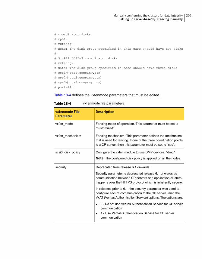
# coordinator disks
# cps1=
# vxfendg=
# Note: The disk group specified in this case should have two disks
#
# 3. All SCSI-3 coordinator disks
# vxfendg=
# Note: The disk group specified in case should have three disks
# cps1=[cps1.company.com]
# cps2=[cps2.company.com]
# cps3=[cps3.company.com]
# port=443
Table 18-4 defines the vxfenmode parameters that must be edited.
Table 18-4 vxfenmode file parameters
Descriptionvxfenmode FileParameter
Fencing mode of operation. This parameter must be set to“customized”.
vxfen_mode
Fencing mechanism. This parameter defines the mechanismthat is used for fencing. If one of the three coordination pointsis a CP server, then this parameter must be set to “cps”.
vxfen_mechanism
Configure the vxfen module to use DMP devices, "dmp".
Note: The configured disk policy is applied on all the nodes.
scsi3_disk_policy
Deprecated from release 6.1 onwards.
Security parameter is deprecated release 6.1 onwards ascommunication between CP servers and application clustershappens over the HTTPS protocol which is inherently secure.
In releases prior to 6.1, the security parameter was used toconfigure secure communication to the CP server using theVxAT (Veritas Authentication Service) options. The options are:
■ 0 - Do not use Veritas Authentication Service for CP servercommunication
■ 1 - Use Veritas Authentication Service for CP servercommunication
security
302Manually configuring the clusters for data integritySetting up server-based I/O fencing manually
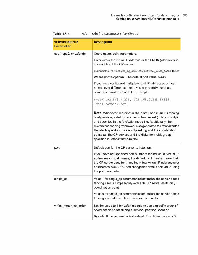
Table 18-4 vxfenmode file parameters (continued)
Descriptionvxfenmode FileParameter
Coordination point parameters.
Enter either the virtual IP address or the FQHN (whichever isaccessible) of the CP server.
cps<number>=[virtual_ip_address/virtual_host_name]:port
Where port is optional. The default port value is 443.
If you have configured multiple virtual IP addresses or hostnames over different subnets, you can specify these ascomma-separated values. For example:
cps1=[192.168.0.23],[192.168.0.24]:58888,[cps1.company.com]
Note: Whenever coordinator disks are used in an I/O fencingconfiguration, a disk group has to be created (vxfencoorddg)and specified in the /etc/vxfenmode file. Additionally, thecustomized fencing framework also generates the /etc/vxfentabfile which specifies the security setting and the coordinationpoints (all the CP servers and the disks from disk groupspecified in /etc/vxfenmode file).
cps1, cps2, or vxfendg
Default port for the CP server to listen on.
If you have not specified port numbers for individual virtual IPaddresses or host names, the default port number value thatthe CP server uses for those individual virtual IP addresses orhost names is 443. You can change this default port value usingthe port parameter.
port
Value 1 for single_cp parameter indicates that the server-basedfencing uses a single highly available CP server as its onlycoordination point.
Value 0 for single_cp parameter indicates that the server-basedfencing uses at least three coordination points.
single_cp
Set the value to 1 for vxfen module to use a specific order ofcoordination points during a network partition scenario.
By default the parameter is disabled. The default value is 0.
vxfen_honor_cp_order
303Manually configuring the clusters for data integritySetting up server-based I/O fencing manually

Configuring CoordPoint agent to monitor coordination pointsThe following procedure describes how to manually configure the CoordPoint agentto monitor coordination points.
The CoordPoint agent can monitor CP servers and SCSI-3 disks.
See the Symantec Cluster Server Bundled Agents Reference Guide for moreinformation on the agent.
To configure CoordPoint agent to monitor coordination points
1 Ensure that your VCS cluster has been properly installed and configured withfencing enabled.
2 Create a parallel service group vxfen and add a coordpoint resource to thevxfen service group using the following commands:
# haconf -makerw
# hagrp -add vxfen
# hagrp -modify vxfen SystemList sys1 0 sys2 1
# hagrp -modify vxfen AutoFailOver 0
# hagrp -modify vxfen Parallel 1
# hagrp -modify vxfen SourceFile "./main.cf"
# hares -add coordpoint CoordPoint vxfen
# hares -modify coordpoint FaultTolerance 0
# hares -override coordpoint LevelTwoMonitorFreq
# hares -modify coordpoint LevelTwoMonitorFreq 5
# hares -modify coordpoint Enabled 1
# haconf -dump -makero
3 Configure the Phantom resource for the vxfen disk group.
# haconf -makerw
# hares -add RES_phantom_vxfen Phantom vxfen
# hares -modify RES_phantom_vxfen Enabled 1
# haconf -dump -makero
304Manually configuring the clusters for data integritySetting up server-based I/O fencing manually
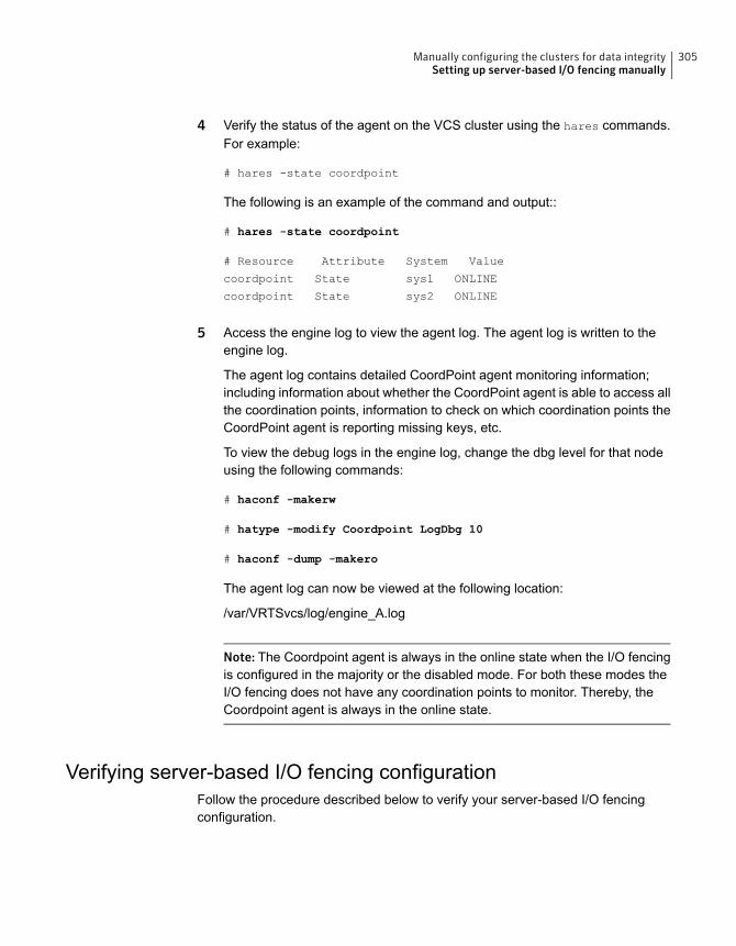
4 Verify the status of the agent on the VCS cluster using the hares commands.For example:
# hares -state coordpoint
The following is an example of the command and output::
# hares -state coordpoint
# Resource Attribute System Value
coordpoint State sys1 ONLINE
coordpoint State sys2 ONLINE
5 Access the engine log to view the agent log. The agent log is written to theengine log.
The agent log contains detailed CoordPoint agent monitoring information;including information about whether the CoordPoint agent is able to access allthe coordination points, information to check on which coordination points theCoordPoint agent is reporting missing keys, etc.
To view the debug logs in the engine log, change the dbg level for that nodeusing the following commands:
# haconf -makerw
# hatype -modify Coordpoint LogDbg 10
# haconf -dump -makero
The agent log can now be viewed at the following location:
/var/VRTSvcs/log/engine_A.log
Note: The Coordpoint agent is always in the online state when the I/O fencingis configured in the majority or the disabled mode. For both these modes theI/O fencing does not have any coordination points to monitor. Thereby, theCoordpoint agent is always in the online state.
Verifying server-based I/O fencing configurationFollow the procedure described below to verify your server-based I/O fencingconfiguration.
305Manually configuring the clusters for data integritySetting up server-based I/O fencing manually
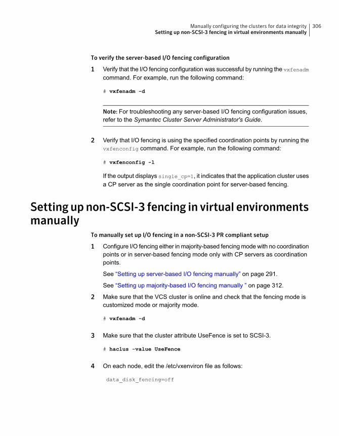
To verify the server-based I/O fencing configuration
1 Verify that the I/O fencing configuration was successful by running the vxfenadm
command. For example, run the following command:
# vxfenadm -d
Note: For troubleshooting any server-based I/O fencing configuration issues,refer to the Symantec Cluster Server Administrator's Guide.
2 Verify that I/O fencing is using the specified coordination points by running thevxfenconfig command. For example, run the following command:
# vxfenconfig -l
If the output displays single_cp=1, it indicates that the application cluster usesa CP server as the single coordination point for server-based fencing.
Setting upnon-SCSI-3 fencing in virtual environmentsmanually
To manually set up I/O fencing in a non-SCSI-3 PR compliant setup
1 Configure I/O fencing either in majority-based fencing mode with no coordinationpoints or in server-based fencing mode only with CP servers as coordinationpoints.
See “Setting up server-based I/O fencing manually” on page 291.
See “Setting up majority-based I/O fencing manually ” on page 312.
2 Make sure that the VCS cluster is online and check that the fencing mode iscustomized mode or majority mode.
# vxfenadm -d
3 Make sure that the cluster attribute UseFence is set to SCSI-3.
# haclus -value UseFence
4 On each node, edit the /etc/vxenviron file as follows:
data_disk_fencing=off
306Manually configuring the clusters for data integritySetting up non-SCSI-3 fencing in virtual environments manually
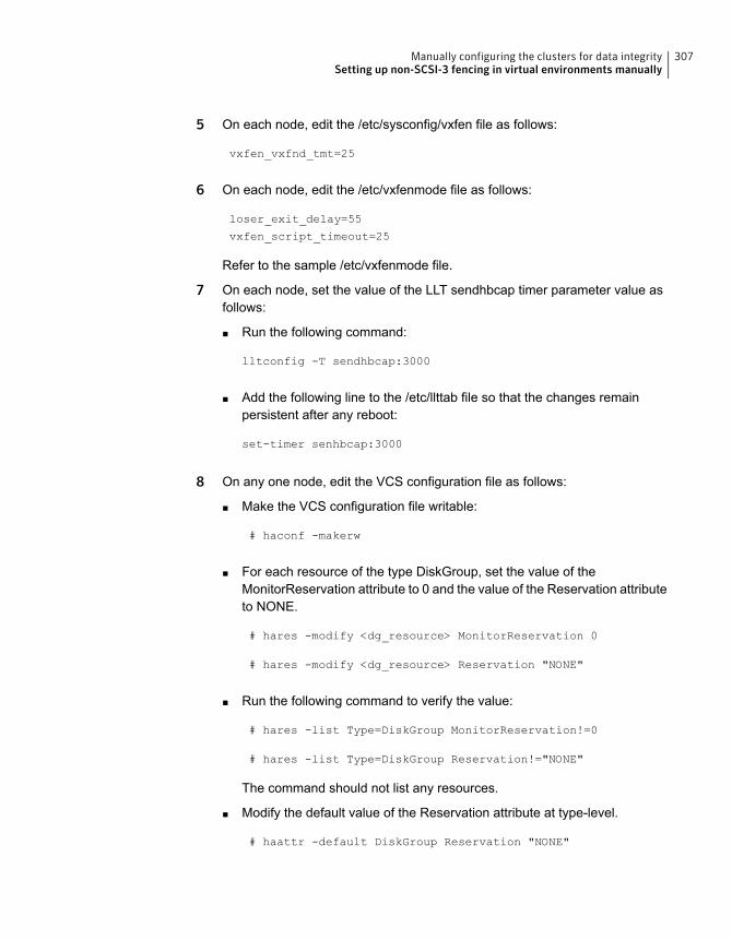
5 On each node, edit the /etc/sysconfig/vxfen file as follows:
vxfen_vxfnd_tmt=25
6 On each node, edit the /etc/vxfenmode file as follows:
loser_exit_delay=55
vxfen_script_timeout=25
Refer to the sample /etc/vxfenmode file.
7 On each node, set the value of the LLT sendhbcap timer parameter value asfollows:
■ Run the following command:
lltconfig -T sendhbcap:3000
■ Add the following line to the /etc/llttab file so that the changes remainpersistent after any reboot:
set-timer senhbcap:3000
8 On any one node, edit the VCS configuration file as follows:
■ Make the VCS configuration file writable:
# haconf -makerw
■ For each resource of the type DiskGroup, set the value of theMonitorReservation attribute to 0 and the value of the Reservation attributeto NONE.
# hares -modify <dg_resource> MonitorReservation 0
# hares -modify <dg_resource> Reservation "NONE"
■ Run the following command to verify the value:
# hares -list Type=DiskGroup MonitorReservation!=0
# hares -list Type=DiskGroup Reservation!="NONE"
The command should not list any resources.
■ Modify the default value of the Reservation attribute at type-level.
# haattr -default DiskGroup Reservation "NONE"
307Manually configuring the clusters for data integritySetting up non-SCSI-3 fencing in virtual environments manually
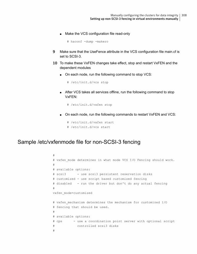
■ Make the VCS configuration file read-only
# haconf -dump -makero
9 Make sure that the UseFence attribute in the VCS configuration file main.cf isset to SCSI-3.
10 To make these VxFEN changes take effect, stop and restart VxFEN and thedependent modules
■ On each node, run the following command to stop VCS:
# /etc/init.d/vcs stop
■ After VCS takes all services offline, run the following command to stopVxFEN:
# /etc/init.d/vxfen stop
■ On each node, run the following commands to restart VxFEN and VCS:
# /etc/init.d/vxfen start
# /etc/init.d/vcs start
Sample /etc/vxfenmode file for non-SCSI-3 fencing
#
# vxfen_mode determines in what mode VCS I/O Fencing should work.
#
# available options:
# scsi3 - use scsi3 persistent reservation disks
# customized - use script based customized fencing
# disabled - run the driver but don't do any actual fencing
#
vxfen_mode=customized
# vxfen_mechanism determines the mechanism for customized I/O
# fencing that should be used.
#
# available options:
# cps - use a coordination point server with optional script
# controlled scsi3 disks
#
308Manually configuring the clusters for data integritySetting up non-SCSI-3 fencing in virtual environments manually

vxfen_mechanism=cps
#
# scsi3_disk_policy determines the way in which I/O fencing
# communicates with the coordination disks. This field is
# required only if customized coordinator disks are being used.
#
# available options:
# dmp - use dynamic multipathing
#
scsi3_disk_policy=dmp
#
# Seconds for which the winning sub cluster waits to allow for the
# losing subcluster to panic & drain I/Os. Useful in the absence of
# SCSI3 based data disk fencing loser_exit_delay=55
#
# Seconds for which vxfend process wait for a customized fencing
# script to complete. Only used with vxfen_mode=customized
# vxfen_script_timeout=25
# security parameter is deprecated release 6.1 onwards since
# communication with CP server will always happen over HTTPS
# which is inherently secure. In pre-6.1 releases, it was used
# to configure secure communication to the cp server using
# VxAT (Veritas Authentication Service) available options:
# 0 - don't use Veritas Authentication Service for cp server
# communication
# 1 - use Veritas Authentication Service for cp server
# communication
security=1
#
# vxfen_honor_cp_order determines the order in which vxfen
# should use the coordination points specified in this file.
#
# available options:
# 0 - vxfen uses a sorted list of coordination points specified
# in this file, the order in which coordination points are specified
# does not matter.
# (default)
# 1 - vxfen uses the coordination points in the same order they are
# specified in this file
309Manually configuring the clusters for data integritySetting up non-SCSI-3 fencing in virtual environments manually
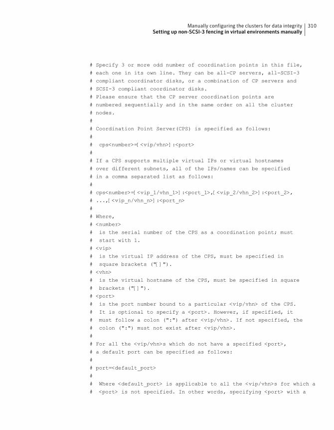
# Specify 3 or more odd number of coordination points in this file,
# each one in its own line. They can be all-CP servers, all-SCSI-3
# compliant coordinator disks, or a combination of CP servers and
# SCSI-3 compliant coordinator disks.
# Please ensure that the CP server coordination points are
# numbered sequentially and in the same order on all the cluster
# nodes.
#
# Coordination Point Server(CPS) is specified as follows:
#
# cps<number>=[<vip/vhn>]:<port>
#
# If a CPS supports multiple virtual IPs or virtual hostnames
# over different subnets, all of the IPs/names can be specified
# in a comma separated list as follows:
#
# cps<number>=[<vip_1/vhn_1>]:<port_1>,[<vip_2/vhn_2>]:<port_2>,
# ...,[<vip_n/vhn_n>]:<port_n>
#
# Where,
# <number>
# is the serial number of the CPS as a coordination point; must
# start with 1.
# <vip>
# is the virtual IP address of the CPS, must be specified in
# square brackets ("[]").
# <vhn>
# is the virtual hostname of the CPS, must be specified in square
# brackets ("[]").
# <port>
# is the port number bound to a particular <vip/vhn> of the CPS.
# It is optional to specify a <port>. However, if specified, it
# must follow a colon (":") after <vip/vhn>. If not specified, the
# colon (":") must not exist after <vip/vhn>.
#
# For all the <vip/vhn>s which do not have a specified <port>,
# a default port can be specified as follows:
#
# port=<default_port>
#
# Where <default_port> is applicable to all the <vip/vhn>s for which a
# <port> is not specified. In other words, specifying <port> with a
310Manually configuring the clusters for data integritySetting up non-SCSI-3 fencing in virtual environments manually
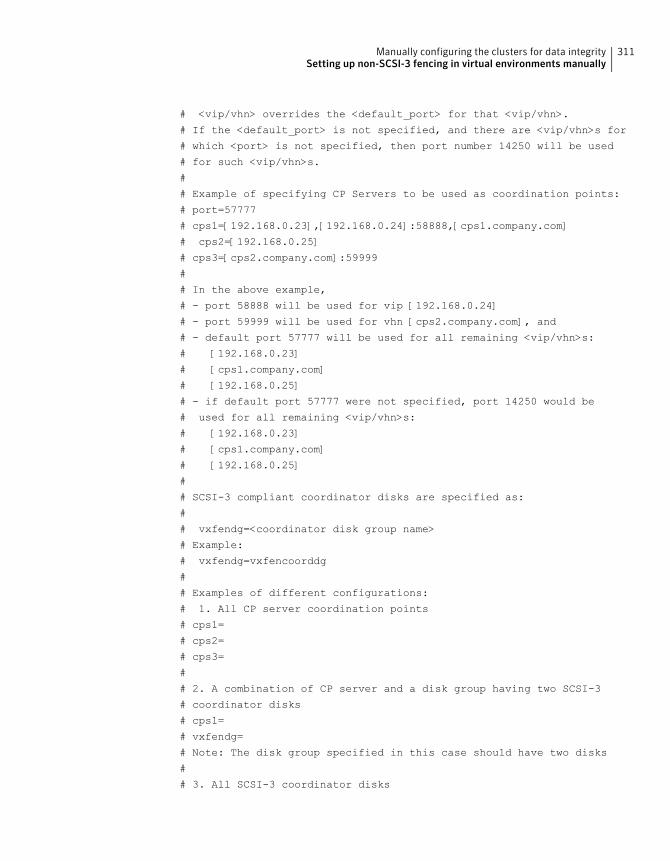
# <vip/vhn> overrides the <default_port> for that <vip/vhn>.
# If the <default_port> is not specified, and there are <vip/vhn>s for
# which <port> is not specified, then port number 14250 will be used
# for such <vip/vhn>s.
#
# Example of specifying CP Servers to be used as coordination points:
# port=57777
# cps1=[192.168.0.23],[192.168.0.24]:58888,[cps1.company.com]
# cps2=[192.168.0.25]
# cps3=[cps2.company.com]:59999
#
# In the above example,
# - port 58888 will be used for vip [192.168.0.24]
# - port 59999 will be used for vhn [cps2.company.com], and
# - default port 57777 will be used for all remaining <vip/vhn>s:
# [192.168.0.23]
# [cps1.company.com]
# [192.168.0.25]
# - if default port 57777 were not specified, port 14250 would be
# used for all remaining <vip/vhn>s:
# [192.168.0.23]
# [cps1.company.com]
# [192.168.0.25]
#
# SCSI-3 compliant coordinator disks are specified as:
#
# vxfendg=<coordinator disk group name>
# Example:
# vxfendg=vxfencoorddg
#
# Examples of different configurations:
# 1. All CP server coordination points
# cps1=
# cps2=
# cps3=
#
# 2. A combination of CP server and a disk group having two SCSI-3
# coordinator disks
# cps1=
# vxfendg=
# Note: The disk group specified in this case should have two disks
#
# 3. All SCSI-3 coordinator disks
311Manually configuring the clusters for data integritySetting up non-SCSI-3 fencing in virtual environments manually
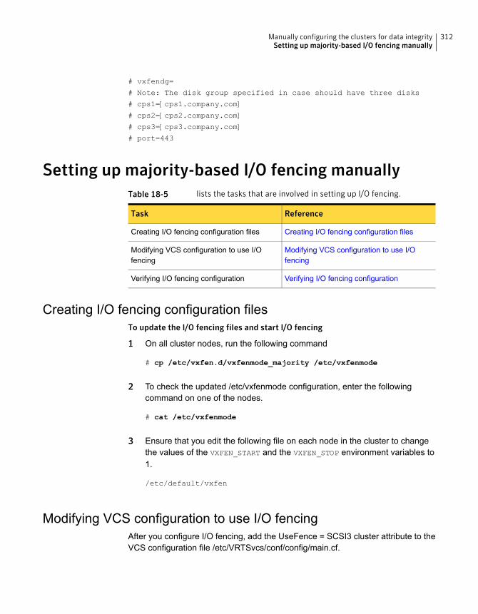
# vxfendg=
# Note: The disk group specified in case should have three disks
# cps1=[cps1.company.com]
# cps2=[cps2.company.com]
# cps3=[cps3.company.com]
# port=443
Setting up majority-based I/O fencing manuallyTable 18-5 lists the tasks that are involved in setting up I/O fencing.
ReferenceTask
Creating I/O fencing configuration filesCreating I/O fencing configuration files
Modifying VCS configuration to use I/Ofencing
Modifying VCS configuration to use I/Ofencing
Verifying I/O fencing configurationVerifying I/O fencing configuration
Creating I/O fencing configuration filesTo update the I/O fencing files and start I/O fencing
1 On all cluster nodes, run the following command
# cp /etc/vxfen.d/vxfenmode_majority /etc/vxfenmode
2 To check the updated /etc/vxfenmode configuration, enter the followingcommand on one of the nodes.
# cat /etc/vxfenmode
3 Ensure that you edit the following file on each node in the cluster to changethe values of the VXFEN_START and the VXFEN_STOP environment variables to1.
/etc/default/vxfen
Modifying VCS configuration to use I/O fencingAfter you configure I/O fencing, add the UseFence = SCSI3 cluster attribute to theVCS configuration file /etc/VRTSvcs/conf/config/main.cf.
312Manually configuring the clusters for data integritySetting up majority-based I/O fencing manually
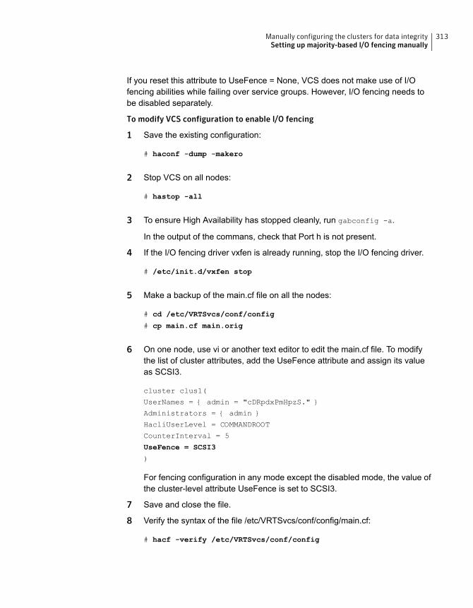
If you reset this attribute to UseFence = None, VCS does not make use of I/Ofencing abilities while failing over service groups. However, I/O fencing needs tobe disabled separately.
To modify VCS configuration to enable I/O fencing
1 Save the existing configuration:
# haconf -dump -makero
2 Stop VCS on all nodes:
# hastop -all
3 To ensure High Availability has stopped cleanly, run gabconfig -a.
In the output of the commans, check that Port h is not present.
4 If the I/O fencing driver vxfen is already running, stop the I/O fencing driver.
# /etc/init.d/vxfen stop
5 Make a backup of the main.cf file on all the nodes:
# cd /etc/VRTSvcs/conf/config
# cp main.cf main.orig
6 On one node, use vi or another text editor to edit the main.cf file. To modifythe list of cluster attributes, add the UseFence attribute and assign its valueas SCSI3.
cluster clus1(
UserNames = { admin = "cDRpdxPmHpzS." }
Administrators = { admin }
HacliUserLevel = COMMANDROOT
CounterInterval = 5
UseFence = SCSI3
)
For fencing configuration in any mode except the disabled mode, the value ofthe cluster-level attribute UseFence is set to SCSI3.
7 Save and close the file.
8 Verify the syntax of the file /etc/VRTSvcs/conf/config/main.cf:
# hacf -verify /etc/VRTSvcs/conf/config
313Manually configuring the clusters for data integritySetting up majority-based I/O fencing manually
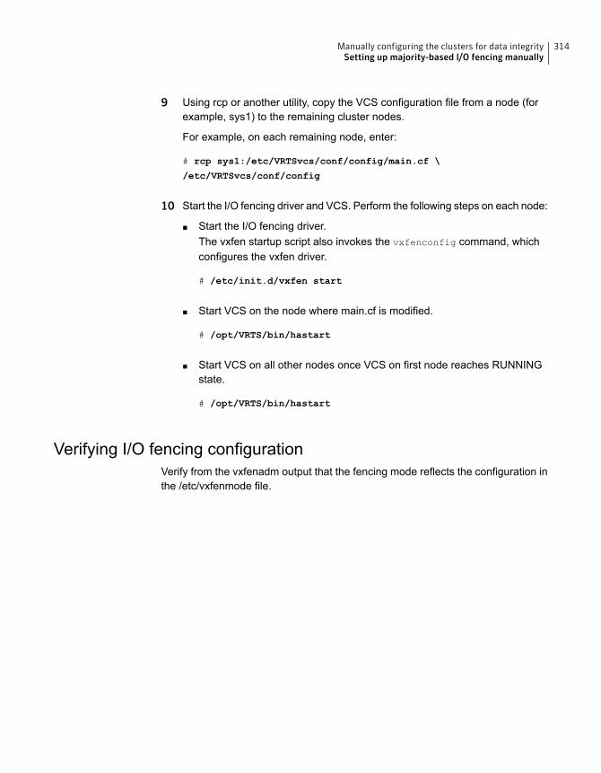
9 Using rcp or another utility, copy the VCS configuration file from a node (forexample, sys1) to the remaining cluster nodes.
For example, on each remaining node, enter:
# rcp sys1:/etc/VRTSvcs/conf/config/main.cf \
/etc/VRTSvcs/conf/config
10 Start the I/O fencing driver and VCS. Perform the following steps on each node:
■ Start the I/O fencing driver.The vxfen startup script also invokes the vxfenconfig command, whichconfigures the vxfen driver.
# /etc/init.d/vxfen start
■ Start VCS on the node where main.cf is modified.
# /opt/VRTS/bin/hastart
■ Start VCS on all other nodes once VCS on first node reaches RUNNINGstate.
# /opt/VRTS/bin/hastart
Verifying I/O fencing configurationVerify from the vxfenadm output that the fencing mode reflects the configuration inthe /etc/vxfenmode file.
314Manually configuring the clusters for data integritySetting up majority-based I/O fencing manually
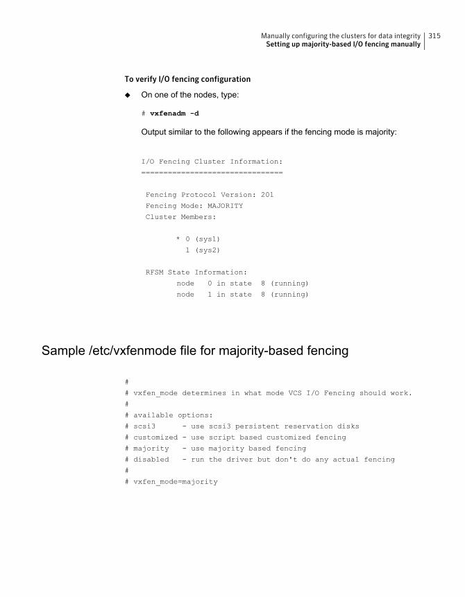
To verify I/O fencing configuration
◆ On one of the nodes, type:
# vxfenadm -d
Output similar to the following appears if the fencing mode is majority:
I/O Fencing Cluster Information:
================================
Fencing Protocol Version: 201
Fencing Mode: MAJORITY
Cluster Members:
* 0 (sys1)
1 (sys2)
RFSM State Information:
node 0 in state 8 (running)
node 1 in state 8 (running)
Sample /etc/vxfenmode file for majority-based fencing
#
# vxfen_mode determines in what mode VCS I/O Fencing should work.
#
# available options:
# scsi3 - use scsi3 persistent reservation disks
# customized - use script based customized fencing
# majority - use majority based fencing
# disabled - run the driver but don't do any actual fencing
#
# vxfen_mode=majority
315Manually configuring the clusters for data integritySetting up majority-based I/O fencing manually
Managing your Symantecdeployments
■ Chapter 19. Performing centralized installations using the Deployment Server
7Section
Performing centralizedinstallations using theDeployment Server
This chapter includes the following topics:
■ About the Deployment Server
■ Deployment Server overview
■ Installing the Deployment Server
■ Setting up a Deployment Server
■ Setting deployment preferences
■ Specifying a non-default repository location
■ Downloading the most recent release information
■ Loading release information and patches on to your Deployment Server
■ Viewing or downloading available release images
■ Viewing or removing repository images stored in your repository
■ Deploying Symantec product updates to your environment
■ Finding out which releases you have installed, and which upgrades or updatesyou may need
■ Defining Install Bundles
■ Creating Install Templates
19Chapter
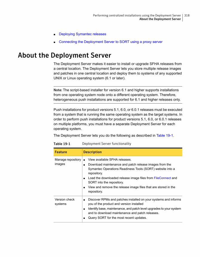
■ Deploying Symantec releases
■ Connecting the Deployment Server to SORT using a proxy server
About the Deployment ServerThe Deployment Server makes it easier to install or upgrade SFHA releases froma central location. The Deployment Server lets you store multiple release imagesand patches in one central location and deploy them to systems of any supportedUNIX or Linux operating system (6.1 or later).
Note: The script-based installer for version 6.1 and higher supports installationsfrom one operating system node onto a different operating system. Therefore,heterogeneous push installations are supported for 6.1 and higher releases only.
Push installations for product versions 5.1, 6.0, or 6.0.1 releases must be executedfrom a system that is running the same operating system as the target systems. Inorder to perform push installations for product versions 5.1, 6.0, or 6.0.1 releaseson multiple platforms, you must have a separate Deployment Server for eachoperating system.
The Deployment Server lets you do the following as described in Table 19-1.
Table 19-1 Deployment Server functionality
DescriptionFeature
■ View available SFHA releases.■ Download maintenance and patch release images from the
Symantec Operations Readiness Tools (SORT) website into arepository.
■ Load the downloaded release image files from FileConnect andSORT into the repository.
■ View and remove the release image files that are stored in therepository.
Manage repositoryimages
■ Discover RPMs and patches installed on your systems and informsyou of the product and version installed
■ Identify base, maintenance, and patch level upgrades to your systemand to download maintenance and patch releases.
■ Query SORT for the most recent updates.
Version checksystems
318Performing centralized installations using the Deployment ServerAbout the Deployment Server
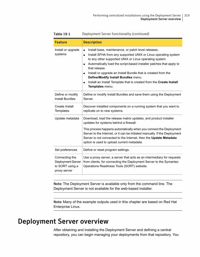
Table 19-1 Deployment Server functionality (continued)
DescriptionFeature
■ Install base, maintenance, or patch level releases.■ Install SFHA from any supported UNIX or Linux operating system
to any other supported UNIX or Linux operating system.■ Automatically load the script-based installer patches that apply to
that release.■ Install or upgrade an Install Bundle that is created from the
Define/Modify Install Bundles menu.■ Install an Install Template that is created from the Create Install
Templates menu.
Install or upgradesystems
Define or modify Install Bundles and save them using the DeploymentServer.
Define or modifyInstall Bundles
Discover installed components on a running system that you want toreplicate on to new systems.
Create InstallTemplates
Download, load the release matrix updates, and product installerupdates for systems behind a firewall.
This process happens automatically when you connect the DeploymentServer to the Internet, or it can be initiated manually. If the DeploymentServer is not connected to the Internet, then the Update Metadataoption is used to upload current metadata.
Update metadata
Define or reset program settings.Set preferences
Use a proxy server, a server that acts as an intermediary for requestsfrom clients, for connecting the Deployment Server to the SymantecOperations Readiness Tools (SORT) website.
Connecting theDeployment Serverto SORT using aproxy server
Note: The Deployment Server is available only from the command line. TheDeployment Server is not available for the web-based installer.
Note: Many of the example outputs used in this chapter are based on Red HatEnterprise Linux.
Deployment Server overviewAfter obtaining and installing the Deployment Server and defining a centralrepository, you can begin managing your deployments from that repository. You
319Performing centralized installations using the Deployment ServerDeployment Server overview
can load and store product images for Symantec products back to version 5.1 inyour Deployment Server. The Deployment Server is a central installation server forstoring and managing your product updates.
Setting up and managing your repository involves the following tasks:
■ Installing the Deployment Server.See “Installing the Deployment Server” on page 320.
■ Setting up a Deployment Server.See “Setting up a Deployment Server” on page 321.
■ Finding out which products you have installed, and which upgrades or updatesyou may need.See “Viewing or downloading available release images” on page 328.
■ Adding release images to your Deployment Server.See “Viewing or downloading available release images” on page 328.
■ Removing release images from your Deployment Server.See “Viewing or removing repository images stored in your repository”on page 333.
■ Defining or modifying Install Bundles to manually install or upgrade a bundle oftwo or more releases.See “Defining Install Bundles” on page 338.
■ Creating Install Templates to discover installed components on a system thatyou want to replicate to another system.See “Creating Install Templates” on page 343.
Later, when your repository is set up, you can use it to deploy Symantec productsto other systems in your environment.
See “Deploying Symantec product updates to your environment” on page 335.
See “Deploying Symantec releases” on page 345.
Installing the Deployment ServerYou can obtain the Deployment Server by either:
■ Installing the Deployment Server manually.
■ Running the Deployment Server after installing at least one Symantec 6.2product.
320Performing centralized installations using the Deployment ServerInstalling the Deployment Server
Note:The VRTSperl and the VRTSsfcpi<version>RPMs are included in all StorageFoundation (SF) products, so installing any Symantec 6.2 product lets you accessthe Deployment Server.
To install theDeployment Servermanuallywithout installing aSymantec 6.2 product
1 Log in as superuser.
2 Mount the installation media.
See “Mounting the product disc” on page 76.
3 Move to the top-level directory on the disc.
# cd /mnt/cdrom/dist_arch
where dist is rhel6, rhel7, or sles11, and arch is x86_64 for RHEL and SLES.
4 Navigate to the following directory:
# cd rpms
5 Run the following command to install the VRTSperl and theVRTSsfcpi<version> RPMs:
# rpm -ivh VRTSperl*.rpm VRTSsfcpi<version>*.rpm
To run the Deployment Server
1 Log in as superuser.
2 Navigate to the following directory:
# cd /opt/VRTS/install
3 Run the Deployment Server.
# ./deploy_sfha
Setting up a Deployment ServerSymantec recommends that you create a dedicated Deployment Server to manageyour product updates.
A Deployment Server is useful for doing the following tasks:
■ Storing release images for the latest upgrades and updates from Symantec ina central repository directory.
321Performing centralized installations using the Deployment ServerSetting up a Deployment Server
■ Installing and updating systems directly by accessing the release images thatare stored within a central repository.
■ Defining or modifying Install Bundles for deploying a bundle of two or morereleases.
■ Discovering installed components on a system that you want to replicate toanother system.
■ Installing Symantec products from the Deployment Server to systems runningany supported platform.
■ Creating a file share on the repository directory provides a convenient, centrallocation from which systems running any supported platform can install the latestSymantec products and updates.
Create a central repository on the Deployment Server to store and manage thefollowing types of Symantec releases:
■ Base releases. These major releases and minor releases are available for allSymantec products. They contain new features, and you can download themfrom FileConnect.
■ Maintenance releases. These releases are available for all Symantec products.They contain bug fixes and a limited number of new features, and you candownload them from the Symantec Operations Readiness Tools (SORT) website.
■ Patches. These releases contain fixes for specific products, and you candownload them from the SORT website.
Note:All base releases and maintenance releases can be deployed using the installscripts that are included in the release. Before version 6.0.1, patches were installedmanually. From the 6.0.1 release and onwards, install scripts are included withpatch releases.
You can set up a Deployment Server with or without Internet access.
■ If you set up a Deployment Server that has Internet access, you can downloadmaintenance releases and patches from Symantec directly. Then, you candeploy them to your systems.Setting up a Deployment Server that has Internet access
■ If you set up a Deployment Server that does not have Internet access, you candownload maintenance releases and patches from Symantec on another systemthat has Internet access. Then, you can load the images onto the DeploymentServer separately.Setting up a Deployment Server that does not have Internet access
322Performing centralized installations using the Deployment ServerSetting up a Deployment Server
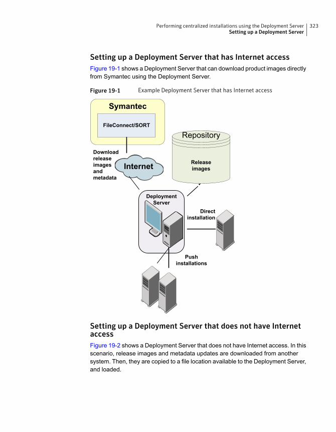
Setting up a Deployment Server that has Internet accessFigure 19-1 shows a Deployment Server that can download product images directlyfrom Symantec using the Deployment Server.
Figure 19-1 Example Deployment Server that has Internet access
DeploymentServer
Symantec
FileConnect/SORT
Downloadreleaseimagesandmetadata
Pushinstallations
Directinstallation
Internet Releaseimages
Repository
Setting up a Deployment Server that does not have InternetaccessFigure 19-2 shows a Deployment Server that does not have Internet access. In thisscenario, release images and metadata updates are downloaded from anothersystem. Then, they are copied to a file location available to the Deployment Server,and loaded.
323Performing centralized installations using the Deployment ServerSetting up a Deployment Server
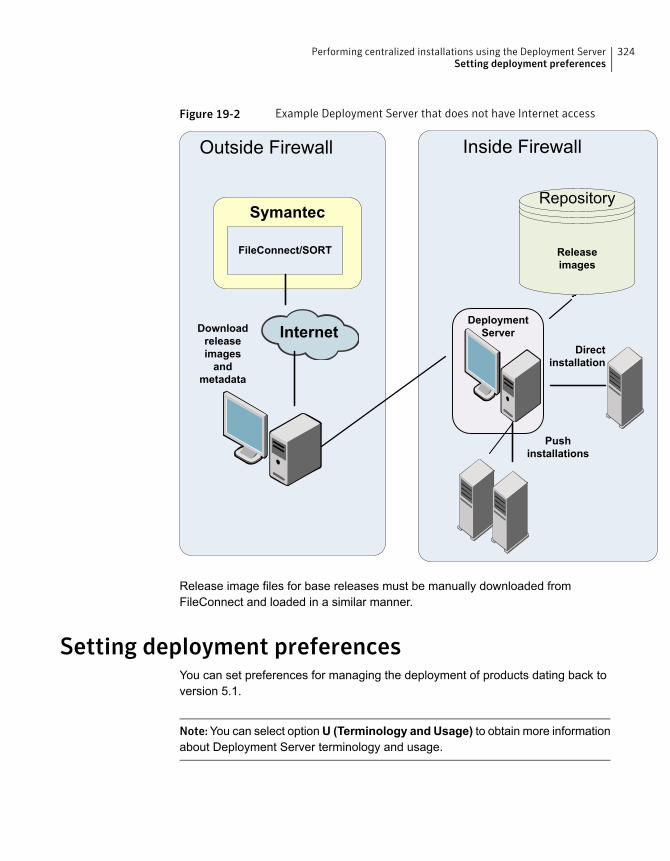
Figure 19-2 Example Deployment Server that does not have Internet access
Inside FirewallOutside Firewall
DeploymentServer
Symantec
FileConnect/SORT
Downloadreleaseimagesand
metadata
Pushinstallations
Directinstallation
Internet
Releaseimages
Repository
Release image files for base releases must be manually downloaded fromFileConnect and loaded in a similar manner.
Setting deployment preferencesYou can set preferences for managing the deployment of products dating back toversion 5.1.
Note:You can select optionU (Terminology and Usage) to obtain more informationabout Deployment Server terminology and usage.
324Performing centralized installations using the Deployment ServerSetting deployment preferences
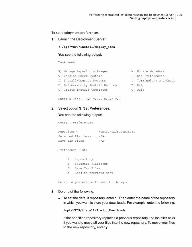
To set deployment preferences
1 Launch the Deployment Server.
# /opt/VRTS/install/deploy_sfha
You see the following output:
Task Menu:
R) Manage Repository Images M) Update Metadata
V) Version Check Systems S) Set Preferences
I) Install/Upgrade Systems U) Terminology and Usage
B) Define/Modify Install Bundles ?) Help
T) Create Install Templates Q) Quit
Enter a Task: [R,M,V,S,I,U,B,?,T,Q]
2 Select option S, Set Preferences.
You see the following output:
Current Preferences:
Repository /opt/VRTS/repository
Selected Platforms N/A
Save Tar Files N/A
Preference List:
1) Repository
2) Selected Platforms
3) Save Tar Files
b) Back to previous menu
Select a preference to set: [1-3,b,q,?]
3 Do one of the following:
■ To set the default repository, enter 1. Then enter the name of the repositoryin which you want to store your downloads. For example, enter the following:
/opt/VRTS/install/ProductDownloads
If the specified repository replaces a previous repository, the installer asksif you want to move all your files into the new repository. To move your filesto the new repository, enter y.
325Performing centralized installations using the Deployment ServerSetting deployment preferences
■ To add or remove a platform, enter 2. You are provided selections for addingor deleting a platform. When a single platform is removed, it becomes N/A,which means that it is not defined. By default, all platforms are chosen.Once you select to add or remove a platform, the platform is added orremoved in the preferences file and the preference platforms are updated.If only one platform is defined, no platform, architecture, distribution, andversion selection menu is displayed.
■ To set the option for saving or removing tar files, enter 3. At the prompt, ifyou want to save the tar files after untarring them, enter y. Or, if you wantto remove tar files after untarring them, enter n.By default, the installer does not remove tar files after the releases havebeen untarred.
Specifying a non-default repository locationYou can specify a repository location other than the default that has been set withinthe system preferences by using the command line option. The command line optionis mainly used to install a release image from a different repository location. Whenyou use the command line option, the designated repository folder is used insteadof the default for the execution time of the script. Using the command line optiondoes not override the repository preference set by the Set Preference menu item.
Note: When you specify a non-default repository, you are allowed only to view therepository (View/Remove Repository), and use the repository to install or upgrade(Install/Upgrade Systems) on other systems.
To use the command line option to specify a non-default repository location
◆ At the command line, to specify a non-default repository location, enter thefollowing:
# ./deploy_sfha -repository repository_path
where repository_path is the location of the repository.
Downloading the most recent release informationUse one of the following methods to obtain a .tar file with the most recent releaseinformation:
■ Download a copy from the SORT website.
■ Run the Deployment Server from a system that has Internet access.
326Performing centralized installations using the Deployment ServerSpecifying a non-default repository location
To obtain a data file by downloading a copy from the SORT website
1 Download the .tar file from the SORT site at:
https://sort.symantec.com/support/related_links/offline-release-updates
2 Click on deploy_sfha.tar [Download], and save the file to your desktop.
To obtain a data file by running the Deployment Server from a systemwith Internetaccess
1 Run the Deployment Server. Enter the following:
# /opt/VRTS/install/deploy_sfha
2 Select option M, Update Metadata.
You see the following output:
The Update Metadata option is used to load release matrix updates on to systems that do
not have an Internet connection with SORT (https://sort.symantec.com). Your system has a
connection with SORT and is able to receive updates. No action is necessary unless you
would like to create a file to update another Deployment Server system.
1) Download release matrix updates and installer patches
2) Load an update tar file
b) Back to previous menu
Select the option: [1-2,b,q,?]
3 Select option 1, Download release matrix updates and installer patches.
Loading release information and patches on to yourDeployment Server
In this procedure, the Internet-enabled system is the system to which youdownloaded the deploy_sfha.tar file.
See “Downloading the most recent release information” on page 326.
327Performing centralized installations using the Deployment ServerLoading release information and patches on to your Deployment Server
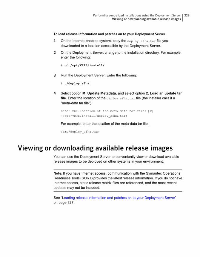
To load release information and patches on to your Deployment Server
1 On the Internet-enabled system, copy the deploy_sfha.tar file youdownloaded to a location accessible by the Deployment Server.
2 On the Deployment Server, change to the installation directory. For example,enter the following:
# cd /opt/VRTS/install/
3 Run the Deployment Server. Enter the following:
# ./deploy_sfha
4 Select option M, Update Metadata, and select option 2, Load an update tarfile. Enter the location of the deploy_sfha.tar file (the installer calls it a"meta-data tar file").
Enter the location of the meta-data tar file: [b]
(/opt/VRTS/install/deploy_sfha.tar)
For example, enter the location of the meta-data tar file:
/tmp/deploy_sfha.tar
Viewing or downloading available release imagesYou can use the Deployment Server to conveniently view or download availablerelease images to be deployed on other systems in your environment.
Note: If you have Internet access, communication with the Symantec OperationsReadiness Tools (SORT) provides the latest release information. If you do not haveInternet access, static release matrix files are referenced, and the most recentupdates may not be included.
See “Loading release information and patches on to your Deployment Server”on page 327.
328Performing centralized installations using the Deployment ServerViewing or downloading available release images
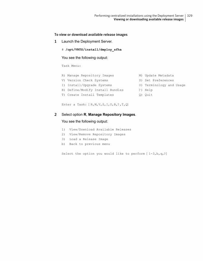
To view or download available release images
1 Launch the Deployment Server.
# /opt/VRTS/install/deploy_sfha
You see the following output:
Task Menu:
R) Manage Repository Images M) Update Metadata
V) Version Check Systems S) Set Preferences
I) Install/Upgrade Systems U) Terminology and Usage
B) Define/Modify Install Bundles ?) Help
T) Create Install Templates Q) Quit
Enter a Task: [R,M,V,S,I,U,B,?,T,Q]
2 Select option R, Manage Repository Images.
You see the following output:
1) View/Download Available Releases
2) View/Remove Repository Images
3) Load a Release Image
b) Back to previous menu
Select the option you would like to perform [1-3,b,q,?]
329Performing centralized installations using the Deployment ServerViewing or downloading available release images
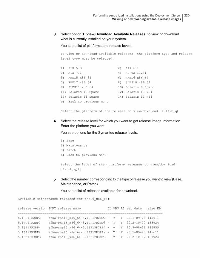
3 Select option 1, View/Download Available Releases, to view or downloadwhat is currently installed on your system.
You see a list of platforms and release levels.
To view or download available releases, the platform type and release
level type must be selected.
1) AIX 5.3 2) AIX 6.1
3) AIX 7.1 4) HP-UX 11.31
5) RHEL5 x86_64 6) RHEL6 x86_64
7) RHEL7 x86_64 8) SLES10 x86_64
9) SLES11 x86_64 10) Solaris 9 Sparc
11) Solaris 10 Sparc 12) Solaris 10 x64
13) Solaris 11 Sparc 14) Solaris 11 x64
b) Back to previous menu
Select the platform of the release to view/download [1-14,b,q]
4 Select the release level for which you want to get release image information.Enter the platform you want.
You see options for the Symantec release levels.
1) Base
2) Maintenance
3) Patch
b) Back to previous menu
Select the level of the <platform> releases to view/download
[1-3,b,q,?]
5 Select the number corresponding to the type of release you want to view (Base,Maintenance, or Patch).
You see a list of releases available for download.
Available Maintenance releases for rhel6_x86_64:
release_version SORT_release_name DL OBS AI rel_date size_KB
============================================================================
5.1SP1PR2RP2 sfha-rhel6_x86_64-5.1SP1PR2RP2 - Y Y 2011-09-28 145611
5.1SP1PR2RP3 sfha-rhel6_x86_64-5.1SP1PR2RP3 - Y Y 2012-10-02 153924
5.1SP1PR2RP4 sfha-rhel6_x86_64-5.1SP1PR2RP4 - - Y 2013-08-21 186859
5.1SP1PR3RP2 sfha-rhel6_x86_64-5.1SP1PR3RP2 - Y Y 2011-09-28 145611
5.1SP1PR3RP3 sfha-rhel6_x86_64-5.1SP1PR3RP3 - Y Y 2012-10-02 153924
330Performing centralized installations using the Deployment ServerViewing or downloading available release images
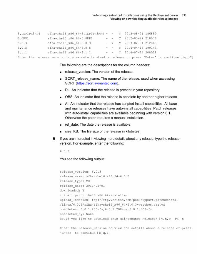
5.1SP1PR3RP4 sfha-rhel6_x86_64-5.1SP1PR3RP4 - - Y 2013-08-21 186859
6.0RP1 sfha-rhel6_x86_64-6.0RP1 - - Y 2012-03-22 210076
6.0.3 sfha-rhel6_x86_64-6.0.3 - Y Y 2013-02-01 212845
6.0.5 sfha-rhel6_x86_64-6.0.5 - - Y 2014-04-15 199143
6.1.1 sfha-rhel6_x86_64-6.1.1 - - Y 2014-07-24 208028
Enter the release_version to view details about a release or press 'Enter' to continue [b,q,?]
The following are the descriptions for the column headers:
■ release_version: The version of the release.
■ SORT_release_name: The name of the release, used when accessingSORT (https://sort.symantec.com).
■ DL: An indicator that the release is present in your repository.
■ OBS: An indicator that the release is obsolete by another higher release.
■ AI: An indicator that the release has scripted install capabilities. All baseand maintenance releases have auto-install capabilities. Patch releaseswith auto-install capabilities are available beginning with version 6.1.Otherwise the patch requires a manual installation.
■ rel_date: The date the release is available.
■ size_KB: The file size of the release in kilobytes.
6 If you are interested in viewing more details about any release, type the releaseversion. For example, enter the following:
6.0.3
You see the following output:
release_version: 6.0.3
release_name: sfha-rhel6_x86_64-6.0.3
release_type: MR
release_date: 2013-02-01
downloaded: Y
install_path: rhel6_x86_64/installmr
upload_location: ftp://ftp.veritas.com/pub/support/patchcentral
/Linux/6.0.3/sfha/sfha-rhel6_x86_64-6.0.3-patches.tar.gz
obsoletes: 6.0.1.200-fs,6.0.1.200-vm,6.0.1.300-fs
obsoleted_by: None
Would you like to download this Maintenance Release? [y,n,q] (y) n
Enter the release_version to view the details about a release or press
'Enter' to continue [b,q,?]
331Performing centralized installations using the Deployment ServerViewing or downloading available release images
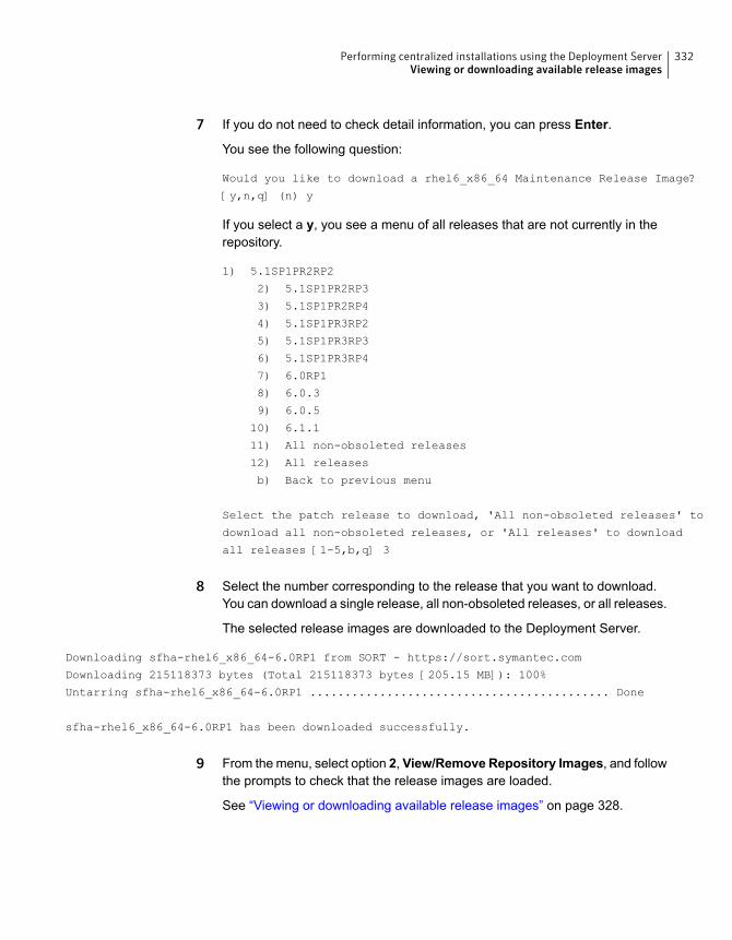
7 If you do not need to check detail information, you can press Enter.
You see the following question:
Would you like to download a rhel6_x86_64 Maintenance Release Image?
[y,n,q] (n) y
If you select a y, you see a menu of all releases that are not currently in therepository.
1) 5.1SP1PR2RP2
2) 5.1SP1PR2RP3
3) 5.1SP1PR2RP4
4) 5.1SP1PR3RP2
5) 5.1SP1PR3RP3
6) 5.1SP1PR3RP4
7) 6.0RP1
8) 6.0.3
9) 6.0.5
10) 6.1.1
11) All non-obsoleted releases
12) All releases
b) Back to previous menu
Select the patch release to download, 'All non-obsoleted releases' to
download all non-obsoleted releases, or 'All releases' to download
all releases [1-5,b,q] 3
8 Select the number corresponding to the release that you want to download.You can download a single release, all non-obsoleted releases, or all releases.
The selected release images are downloaded to the Deployment Server.
Downloading sfha-rhel6_x86_64-6.0RP1 from SORT - https://sort.symantec.com
Downloading 215118373 bytes (Total 215118373 bytes [205.15 MB]): 100%
Untarring sfha-rhel6_x86_64-6.0RP1 ........................................... Done
sfha-rhel6_x86_64-6.0RP1 has been downloaded successfully.
9 From the menu, select option 2, View/Remove Repository Images, and followthe prompts to check that the release images are loaded.
See “Viewing or downloading available release images” on page 328.
332Performing centralized installations using the Deployment ServerViewing or downloading available release images
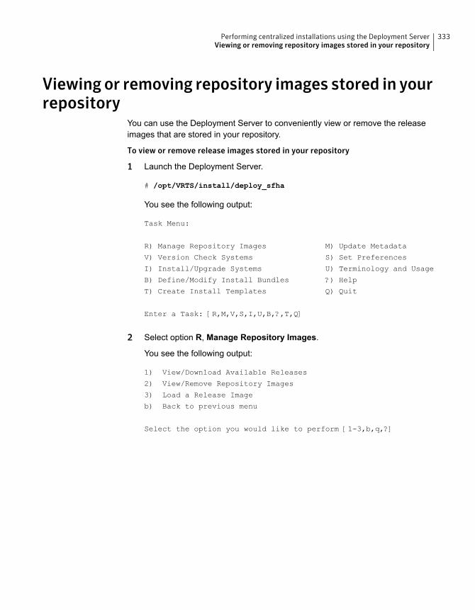
Viewing or removing repository images stored in yourrepository
You can use the Deployment Server to conveniently view or remove the releaseimages that are stored in your repository.
To view or remove release images stored in your repository
1 Launch the Deployment Server.
# /opt/VRTS/install/deploy_sfha
You see the following output:
Task Menu:
R) Manage Repository Images M) Update Metadata
V) Version Check Systems S) Set Preferences
I) Install/Upgrade Systems U) Terminology and Usage
B) Define/Modify Install Bundles ?) Help
T) Create Install Templates Q) Quit
Enter a Task: [R,M,V,S,I,U,B,?,T,Q]
2 Select option R, Manage Repository Images.
You see the following output:
1) View/Download Available Releases
2) View/Remove Repository Images
3) Load a Release Image
b) Back to previous menu
Select the option you would like to perform [1-3,b,q,?]
333Performing centralized installations using the Deployment ServerViewing or removing repository images stored in your repository
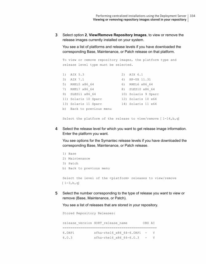
3 Select option 2, View/Remove Repository Images, to view or remove therelease images currently installed on your system.
You see a list of platforms and release levels if you have downloaded thecorresponding Base, Maintenance, or Patch release on that platform.
To view or remove repository images, the platform type and
release level type must be selected.
1) AIX 5.3 2) AIX 6.1
3) AIX 7.1 4) HP-UX 11.31
5) RHEL5 x86_64 6) RHEL6 x86_64
7) RHEL7 x86_64 8) SLES10 x86_64
9) SLES11 x86_64 10) Solaris 9 Sparc
11) Solaris 10 Sparc 12) Solaris 10 x64
13) Solaris 11 Sparc 14) Solaris 11 x64
b) Back to previous menu
Select the platform of the release to view/remove [1-14,b,q]
4 Select the release level for which you want to get release image information.Enter the platform you want.
You see options for the Symantec release levels if you have downloaded thecorresponding Base, Maintenance, or Patch release.
1) Base
2) Maintenance
3) Patch
b) Back to previous menu
Select the level of the <platform> releases to view/remove
[1-3,b,q]
5 Select the number corresponding to the type of release you want to view orremove (Base, Maintenance, or Patch).
You see a list of releases that are stored in your repository.
Stored Repository Releases:
release_version SORT_release_name OBS AI
================================================
6.0RP1 sfha-rhel6_x86_64-6.0RP1 - Y
6.0.3 sfha-rhel6_x86_64-6.0.3 - Y
334Performing centralized installations using the Deployment ServerViewing or removing repository images stored in your repository
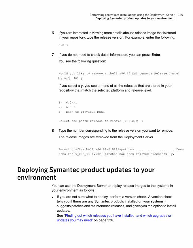
6 If you are interested in viewing more details about a release image that is storedin your repository, type the release version. For example, enter the following:
6.0.3
7 If you do not need to check detail information, you can press Enter.
You see the following question:
Would you like to remove a rhel6_x86_64 Maintenance Release Image?
[y,n,q] (n) y
If you select a y, you see a menu of all the releases that are stored in yourrepository that match the selected platform and release level.
1) 6.0RP1
2) 6.0.3
b) Back to previous menu
Select the patch release to remove [1-2,b,q] 1
8 Type the number corresponding to the release version you want to remove.
The release images are removed from the Deployment Server.
Removing sfha-rhel6_x86_64-6.0RP1-patches ..................... Done
sfha-rhel6_x86_64-6.0RP1-patches has been removed successfully.
Deploying Symantec product updates to yourenvironment
You can use the Deployment Server to deploy release images to the systems inyour environment as follows:
■ If you are not sure what to deploy, perform a version check. A version checktells you if there are any Symantec products installed on your systems. Itsuggests patches and maintenance releases, and gives you the option to installupdates.See “Finding out which releases you have installed, and which upgrades orupdates you may need” on page 336.
335Performing centralized installations using the Deployment ServerDeploying Symantec product updates to your environment
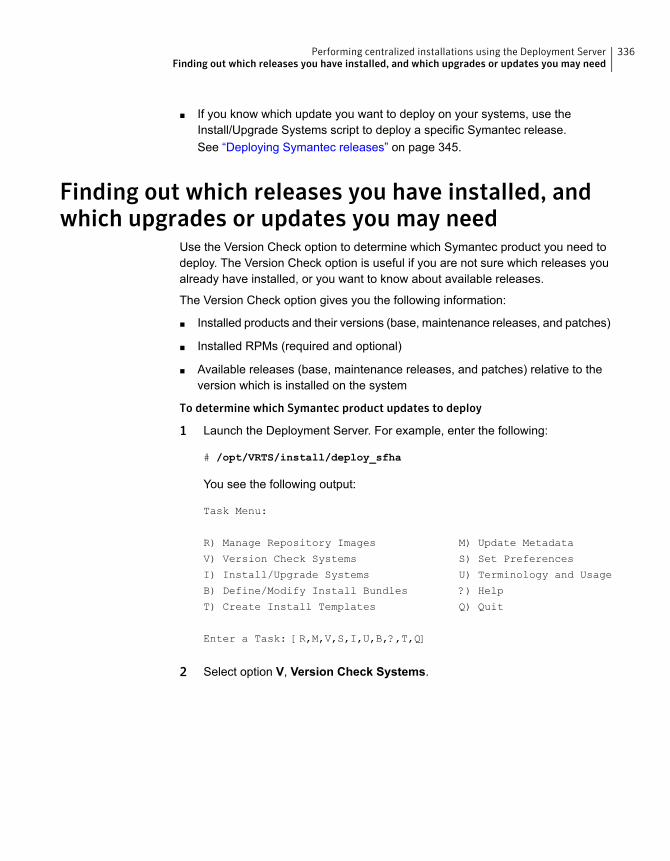
■ If you know which update you want to deploy on your systems, use theInstall/Upgrade Systems script to deploy a specific Symantec release.See “Deploying Symantec releases” on page 345.
Finding out which releases you have installed, andwhich upgrades or updates you may need
Use the Version Check option to determine which Symantec product you need todeploy. The Version Check option is useful if you are not sure which releases youalready have installed, or you want to know about available releases.
The Version Check option gives you the following information:
■ Installed products and their versions (base, maintenance releases, and patches)
■ Installed RPMs (required and optional)
■ Available releases (base, maintenance releases, and patches) relative to theversion which is installed on the system
To determine which Symantec product updates to deploy
1 Launch the Deployment Server. For example, enter the following:
# /opt/VRTS/install/deploy_sfha
You see the following output:
Task Menu:
R) Manage Repository Images M) Update Metadata
V) Version Check Systems S) Set Preferences
I) Install/Upgrade Systems U) Terminology and Usage
B) Define/Modify Install Bundles ?) Help
T) Create Install Templates Q) Quit
Enter a Task: [R,M,V,S,I,U,B,?,T,Q]
2 Select option V, Version Check Systems.
336Performing centralized installations using the Deployment ServerFinding out which releases you have installed, and which upgrades or updates you may need
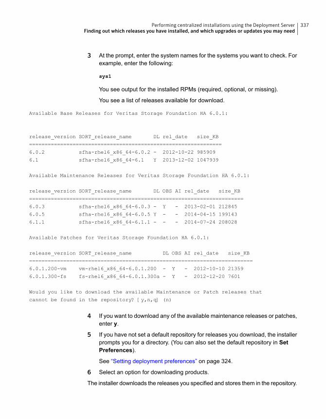
3 At the prompt, enter the system names for the systems you want to check. Forexample, enter the following:
sys1
You see output for the installed RPMs (required, optional, or missing).
You see a list of releases available for download.
Available Base Releases for Veritas Storage Foundation HA 6.0.1:
release_version SORT_release_name DL rel_date size_KB
==============================================================
6.0.2 sfha-rhel6_x86_64-6.0.2 - 2012-10-22 985909
6.1 sfha-rhel6_x86_64-6.1 Y 2013-12-02 1047939
Available Maintenance Releases for Veritas Storage Foundation HA 6.0.1:
release_version SORT_release_name DL OBS AI rel_date size_KB
=====================================================================
6.0.3 sfha-rhel6_x86_64-6.0.3 - Y - 2013-02-01 212845
6.0.5 sfha-rhel6_x86_64-6.0.5 Y - - 2014-04-15 199143
6.1.1 sfha-rhel6_x86_64-6.1.1 - - - 2014-07-24 208028
Available Patches for Veritas Storage Foundation HA 6.0.1:
release_version SORT_release_name DL OBS AI rel_date size_KB
========================================================================
6.0.1.200-vm vm-rhel6_x86_64-6.0.1.200 - Y - 2012-10-10 21359
6.0.1.300-fs fs-rhel6_x86_64-6.0.1.300a - Y - 2012-12-20 7601
Would you like to download the available Maintenance or Patch releases that
cannot be found in the repository? [y,n,q] (n)
4 If you want to download any of the available maintenance releases or patches,enter y.
5 If you have not set a default repository for releases you download, the installerprompts you for a directory. (You can also set the default repository in SetPreferences).
See “Setting deployment preferences” on page 324.
6 Select an option for downloading products.
The installer downloads the releases you specified and stores them in the repository.
337Performing centralized installations using the Deployment ServerFinding out which releases you have installed, and which upgrades or updates you may need

Defining Install BundlesYou can use Install Bundles to directly install the latest base, maintenance, andpatch releases on your system. Install Bundles are a combination of base,maintenance, and patch releases that can be bundled and installed or upgradedin one operation.
Note: Install Bundles can be defined only from version 6.1 or later. The exceptionto this rule is base releases 6.0.1, 6.0.2, or 6.0.4 or later with maintenance release6.0.5 or later.
To define Install Bundles
1 Launch the Deployment Server.
# /opt/VRTS/install/deploy_sfha
You see the following output:
Task Menu:
R) Manage Repository Images M) Update Metadata
V) Version Check Systems S) Set Preferences
I) Install/Upgrade Systems U) Terminology and Usage
B) Define/Modify Install Bundles ?) Help
T) Create Install Templates Q) Quit
Enter a Task: [R,M,V,S,I,U,B,?,T,Q]
2 Select option B, Define/Modify Install Bundles.
You see the following output the first time you enter:
Select a Task:
1) Create a new Install Bundle
b) Back to previous menu
Select the task you would like to perform [1-1,b,q]
338Performing centralized installations using the Deployment ServerDefining Install Bundles
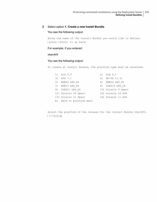
3 Select option 1, Create a new Install Bundle.
You see the following output:
Enter the name of the Install Bundle you would like to define:
{press [Enter] to go back)
For example, if you entered:
rhel605
You see the following output:
To create an Install Bundle, the platform type must be selected:
1) AIX 5.3 2) AIX 6.1
3) AIX 7.1 4) HP-UX 11.31
5) RHEL5 x86_64 6) RHEL6 x86_64
7) RHEL7 x86_64 8) SLES10 x86_64
9) SLES11 x86_64 10) Solaris 9 Sparc
11) Solaris 10 Sparc 12) Solaris 10 x64
13) Solaris 11 Sparc 14) Solaris 11 x64
b) Back to previous menu
Select the platform of the release for the Install Bundle rhel605:
[1-14,b,q]
339Performing centralized installations using the Deployment ServerDefining Install Bundles
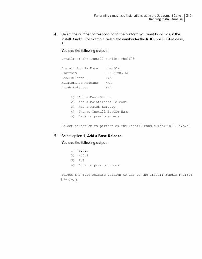
4 Select the number corresponding to the platform you want to include in theInstall Bundle. For example, select the number for theRHEL5 x86_64 release,5.
You see the following output:
Details of the Install Bundle: rhel605
Install Bundle Name rhel605
Platform RHEL5 x86_64
Base Release N/A
Maintenance Release N/A
Patch Releases N/A
1) Add a Base Release
2) Add a Maintenance Release
3) Add a Patch Release
4) Change Install Bundle Name
b) Back to previous menu
Select an action to perform on the Install Bundle rhel605 [1-4,b,q]
5 Select option 1, Add a Base Release.
You see the following output:
1) 6.0.1
2) 6.0.2
3) 6.1
b) Back to previous menu
Select the Base Release version to add to the Install Bundle rhel605
[1-3,b,q]
340Performing centralized installations using the Deployment ServerDefining Install Bundles
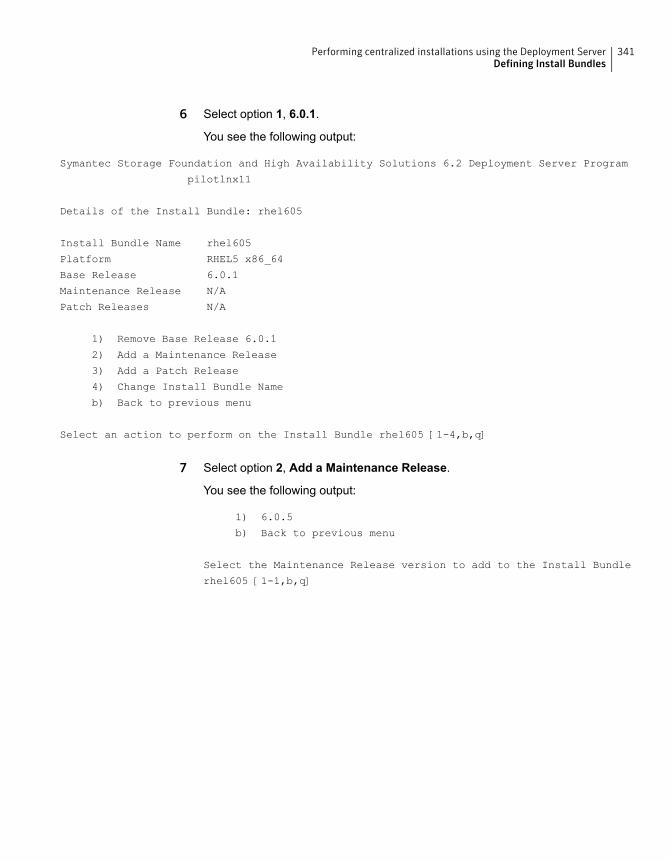
6 Select option 1, 6.0.1.
You see the following output:
Symantec Storage Foundation and High Availability Solutions 6.2 Deployment Server Program
pilotlnx11
Details of the Install Bundle: rhel605
Install Bundle Name rhel605
Platform RHEL5 x86_64
Base Release 6.0.1
Maintenance Release N/A
Patch Releases N/A
1) Remove Base Release 6.0.1
2) Add a Maintenance Release
3) Add a Patch Release
4) Change Install Bundle Name
b) Back to previous menu
Select an action to perform on the Install Bundle rhel605 [1-4,b,q]
7 Select option 2, Add a Maintenance Release.
You see the following output:
1) 6.0.5
b) Back to previous menu
Select the Maintenance Release version to add to the Install Bundle
rhel605 [1-1,b,q]
341Performing centralized installations using the Deployment ServerDefining Install Bundles
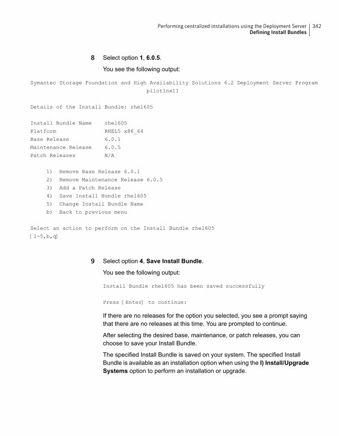
8 Select option 1, 6.0.5.
You see the following output:
Symantec Storage Foundation and High Availability Solutions 6.2 Deployment Server Program
pilotlnx11
Details of the Install Bundle: rhel605
Install Bundle Name rhel605
Platform RHEL5 x86_64
Base Release 6.0.1
Maintenance Release 6.0.5
Patch Releases N/A
1) Remove Base Release 6.0.1
2) Remove Maintenance Release 6.0.5
3) Add a Patch Release
4) Save Install Bundle rhel605
5) Change Install Bundle Name
b) Back to previous menu
Select an action to perform on the Install Bundle rhel605
[1-5,b,q]
9 Select option 4, Save Install Bundle.
You see the following output:
Install Bundle rhel605 has been saved successfully
Press [Enter] to continue:
If there are no releases for the option you selected, you see a prompt sayingthat there are no releases at this time. You are prompted to continue.
After selecting the desired base, maintenance, or patch releases, you canchoose to save your Install Bundle.
The specified Install Bundle is saved on your system. The specified InstallBundle is available as an installation option when using the I) Install/UpgradeSystems option to perform an installation or upgrade.
342Performing centralized installations using the Deployment ServerDefining Install Bundles
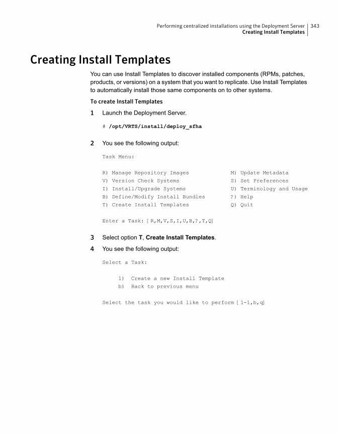
Creating Install TemplatesYou can use Install Templates to discover installed components (RPMs, patches,products, or versions) on a system that you want to replicate. Use Install Templatesto automatically install those same components on to other systems.
To create Install Templates
1 Launch the Deployment Server.
# /opt/VRTS/install/deploy_sfha
2 You see the following output:
Task Menu:
R) Manage Repository Images M) Update Metadata
V) Version Check Systems S) Set Preferences
I) Install/Upgrade Systems U) Terminology and Usage
B) Define/Modify Install Bundles ?) Help
T) Create Install Templates Q) Quit
Enter a Task: [R,M,V,S,I,U,B,?,T,Q]
3 Select option T, Create Install Templates.
4 You see the following output:
Select a Task:
1) Create a new Install Template
b) Back to previous menu
Select the task you would like to perform [1-1,b,q]
343Performing centralized installations using the Deployment ServerCreating Install Templates
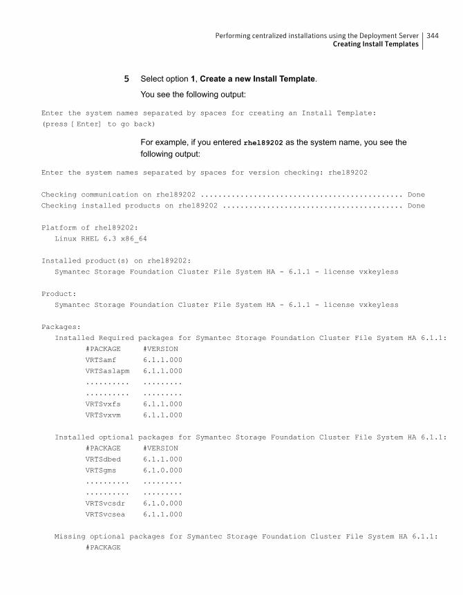
5 Select option 1, Create a new Install Template.
You see the following output:
Enter the system names separated by spaces for creating an Install Template:
(press [Enter] to go back)
For example, if you entered rhel89202 as the system name, you see thefollowing output:
Enter the system names separated by spaces for version checking: rhel89202
Checking communication on rhel89202 .............................................. Done
Checking installed products on rhel89202 ......................................... Done
Platform of rhel89202:
Linux RHEL 6.3 x86_64
Installed product(s) on rhel89202:
Symantec Storage Foundation Cluster File System HA - 6.1.1 - license vxkeyless
Product:
Symantec Storage Foundation Cluster File System HA - 6.1.1 - license vxkeyless
Packages:
Installed Required packages for Symantec Storage Foundation Cluster File System HA 6.1.1:
#PACKAGE #VERSION
VRTSamf 6.1.1.000
VRTSaslapm 6.1.1.000
.......... .........
.......... .........
VRTSvxfs 6.1.1.000
VRTSvxvm 6.1.1.000
Installed optional packages for Symantec Storage Foundation Cluster File System HA 6.1.1:
#PACKAGE #VERSION
VRTSdbed 6.1.1.000
VRTSgms 6.1.0.000
.......... .........
.......... .........
VRTSvcsdr 6.1.0.000
VRTSvcsea 6.1.1.000
Missing optional packages for Symantec Storage Foundation Cluster File System HA 6.1.1:
#PACKAGE
344Performing centralized installations using the Deployment ServerCreating Install Templates

VRTScps
VRTSfssdk
VRTSlvmconv
Summary:
Packages:
17 of 17 required Symantec Storage Foundation Cluster File System HA 6.1.1 packages installed
8 of 11 optional Symantec Storage Foundation Cluster File System HA 6.1.1 packages installed
Installed Public and Private Hot Fixes for Symantec Storage Foundation Cluster File
System HA 6.1.1:
None
Would you like to generate a template file based on the above release information? [y,n,q] (y)
1) rhel89202
b) Back to previous menu
Select a machine list to generate the template file [1-1,b,q]
6 Select option 1, rhel89202.
You see the following output:
Enter the name of the Install Template you would like to define:
(press [Enter] to go back)
7 Enter the name of your Install Template. For example, if you enterMyTemplateas the name for your Install Template, you would see the following:
Install Template MyTemplate has been saved successfully
Press [Enter] to continue:
All of the necessary information is stored in the Install Template you created.
Deploying Symantec releasesYou can use the Deployment Server to deploy your licensed Symantec productsdating back to version 5.1. If you know which product version you want to install,follow the steps in this section to install it.
You can use the Deployment Server to install the following:
345Performing centralized installations using the Deployment ServerDeploying Symantec releases
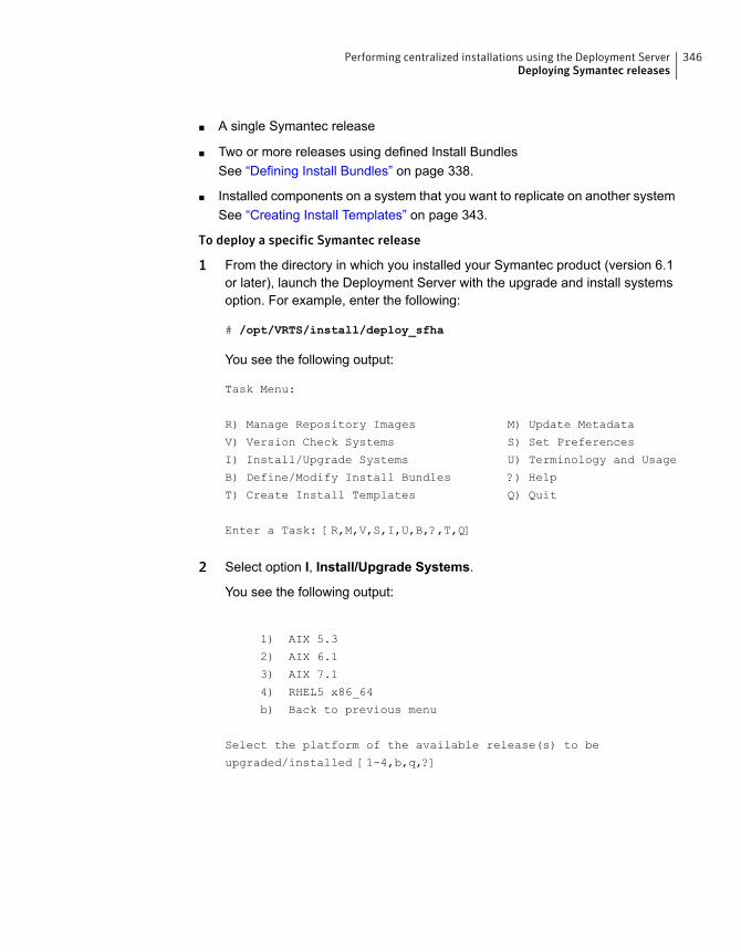
■ A single Symantec release
■ Two or more releases using defined Install BundlesSee “Defining Install Bundles” on page 338.
■ Installed components on a system that you want to replicate on another systemSee “Creating Install Templates” on page 343.
To deploy a specific Symantec release
1 From the directory in which you installed your Symantec product (version 6.1or later), launch the Deployment Server with the upgrade and install systemsoption. For example, enter the following:
# /opt/VRTS/install/deploy_sfha
You see the following output:
Task Menu:
R) Manage Repository Images M) Update Metadata
V) Version Check Systems S) Set Preferences
I) Install/Upgrade Systems U) Terminology and Usage
B) Define/Modify Install Bundles ?) Help
T) Create Install Templates Q) Quit
Enter a Task: [R,M,V,S,I,U,B,?,T,Q]
2 Select option I, Install/Upgrade Systems.
You see the following output:
1) AIX 5.3
2) AIX 6.1
3) AIX 7.1
4) RHEL5 x86_64
b) Back to previous menu
Select the platform of the available release(s) to be
upgraded/installed [1-4,b,q,?]
346Performing centralized installations using the Deployment ServerDeploying Symantec releases

3 Select the number corresponding to the platform for the release you want todeploy. For example, select the number for the RHEL5 x86_64 release or theAIX 6.1 release.
You see the following output:
1) Install/Upgrade systems using a single release
2) Install/Upgrade systems using an Install Bundle
3) Install systems using an Install Template
b) Back to previous menu
Select the method by which you want to Install/Upgrade your systems
[1-3,b,q]
4 Section option 1, Install/Upgrade systems using a single release if you wantto deploy a specific Symantec release.
Select a Symantec product release.
The installation script is executed and the release is deployed on the specifiedserver.
To deploy an Install Bundle
1 Follow Steps 1 - 3.
2 Select option 2, Install/Upgrade systems using an Install Bundle.
You see the following output:
1) <NameofInstallBundle1>
2) <NameofInstallBundle2>
b) Back to previous menu
Select the bundle to be installed/upgraded [1-2,b,q]
You see the following output:
Enter the platform target system name(s) separated by spaces:
[press [Enter] to go back)
3 Enter the name of the target system for which you want to install or upgradethe Install Bundle.
The installation script for the selected Install Bundle is executed, and the InstallBundle is deployed on the specified target system.
347Performing centralized installations using the Deployment ServerDeploying Symantec releases
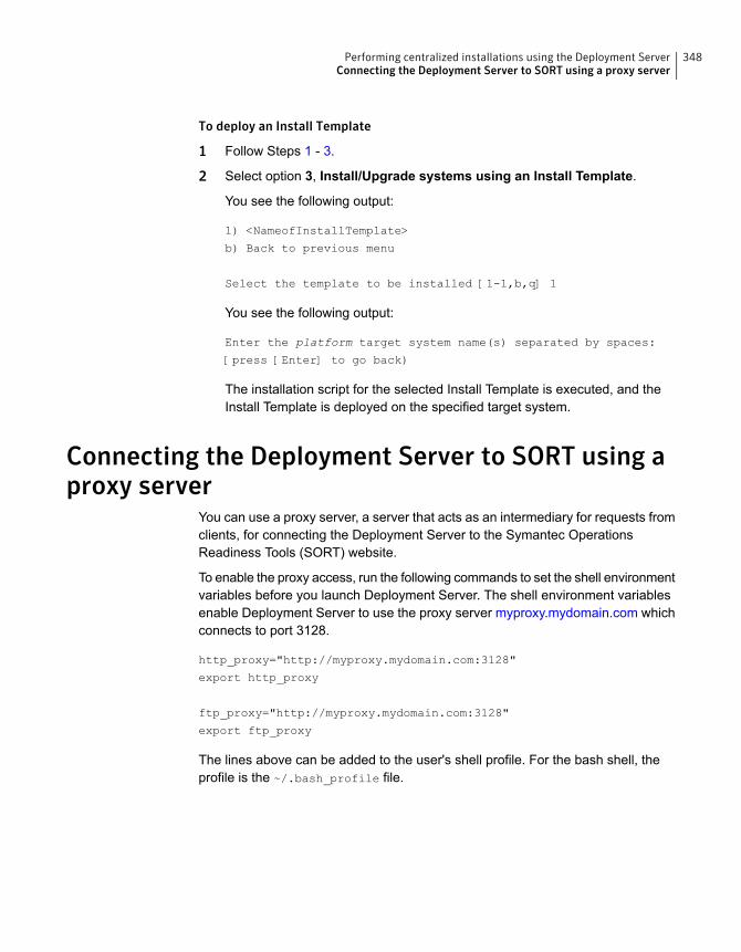
To deploy an Install Template
1 Follow Steps 1 - 3.
2 Select option 3, Install/Upgrade systems using an Install Template.
You see the following output:
1) <NameofInstallTemplate>
b) Back to previous menu
Select the template to be installed [1-1,b,q] 1
You see the following output:
Enter the platform target system name(s) separated by spaces:
[press [Enter] to go back)
The installation script for the selected Install Template is executed, and theInstall Template is deployed on the specified target system.
Connecting the Deployment Server to SORT using aproxy server
You can use a proxy server, a server that acts as an intermediary for requests fromclients, for connecting the Deployment Server to the Symantec OperationsReadiness Tools (SORT) website.
To enable the proxy access, run the following commands to set the shell environmentvariables before you launch Deployment Server. The shell environment variablesenable Deployment Server to use the proxy server myproxy.mydomain.com whichconnects to port 3128.
http_proxy="http://myproxy.mydomain.com:3128"
export http_proxy
ftp_proxy="http://myproxy.mydomain.com:3128"
export ftp_proxy
The lines above can be added to the user's shell profile. For the bash shell, theprofile is the ~/.bash_profile file.
348Performing centralized installations using the Deployment ServerConnecting the Deployment Server to SORT using a proxy server
Upgrading VCS
■ Chapter 20. Planning to upgrade VCS
■ Chapter 21. Performing a typical VCS upgrade using the installer
■ Chapter 22. Performing an online upgrade
■ Chapter 23. Performing a phased upgrade of VCS
■ Chapter 24. Performing an automated VCS upgrade using response files
■ Chapter 25. Performing a rolling upgrade
8Section
Planning to upgrade VCS
This chapter includes the following topics:
■ About upgrading to VCS 6.2
■ Supported upgrade paths for VCS 6.2
■ Upgrading VCS in secure enterprise environments
■ Considerations for upgrading secure VCS 5.x clusters to VCS 6.2
■ Considerations for upgrading VCS to 6.2 on systems configured with an Oracleresource
■ Considerations for upgrading secure VCS clusters to VCS 6.2
■ Considerations for upgrading secure CP servers
■ Considerations for upgrading secure CP clients
■ Setting up trust relationship between CP server and CP clients manually
■ Using Install Bundles to simultaneously install or upgrade full releases (base,maintenance, rolling patch), and individual patches
About upgrading to VCS 6.2When you upgrade to VCS 6.2, you need not reconfigure application monitoringwith VCS. All existing monitoring configurations are preserved.
You can upgrade VCS using one of the following methods:
■ Typical upgrade using product installer or the installvcsSee “Supported upgrade paths for VCS 6.2” on page 351.See “Upgrading VCS using the script-based installer” on page 362.
■ Typical upgrade using Veritas web installer
20Chapter
See “Supported upgrade paths for VCS 6.2” on page 351.See “Upgrading VCS using the web-based installer” on page 364.
■ Performing an online upgradePerform a script-based or web-based online upgrade of your installation toupgrade VCS without stopping your applications. The supported upgrade pathsfor the online upgrades are same as those documented under the script andweb-based upgrades.See “Supported upgrade paths for VCS 6.2” on page 351.See “Upgrading VCS online using the script-based installer” on page 368.See “Upgrading VCS online using the web-based installer” on page 369.
■ Phased upgrade to reduce downtimeSee “Performing a phased upgrade using the script-based installer” on page 375.
■ Automated upgrade using response filesSee “Supported upgrade paths for VCS 6.2” on page 351.See “Upgrading VCS using response files” on page 390.
■ Rolling upgrade to minimize downtimeSee “Performing a rolling upgrade of VCS using the web-based installer”on page 404.
You can upgrade VCS 6.2 to Storage Foundation High Availability 6.2 using theproduct installer or response files.
See the Symantec Storage Foundation and High Availability Installation Guide.
Note: In a VMware virtual environment, you can use the vSphere Client to directlyinstall VCS and supported high availability agents (together called guestcomponents) on the guest virtual machines. For details, see the Symantec HighAvailability Solution Guide for VMware.
Supported upgrade paths for VCS 6.2The following tables describe upgrading to 6.2.
351Planning to upgrade VCSSupported upgrade paths for VCS 6.2

Table 20-1 RHEL6 x64 upgrades using the script- or web-based installer
RHEL 6RHEL5Symantec productversions
N/ANo upgrade path exists.Uninstall the product.Upgrade the operatingsystem to one of thesupported Linux versions, andthen use the installer script toinstall 6.2. See the SymantecCluster Server Release Notesfor the supported Linuxversions.
5.1
5.1 RPs
5.1 SP1RP1
Upgrade the operatingsystem to one of thesupported Linux versions, andthen use the installer script toupgrade to 6.2. See theSymantec Cluster ServerRelease Notes for thesupported Linux versions.
N/A5.1 SP1 PR2
Upgrade the operatingsystem to one of thesupported Linux versions, andthen use the installer script toupgrade to 6.2. See theSymantec Cluster ServerRelease Notes for thesupported Linux versions.
No upgrade path exists.Uninstall the product.Upgrade the operatingsystem to one of thesupported Linux versions, andthen use the installer script toinstall 6.2. See the SymantecCluster Server Release Notesfor the supported Linuxversions.
5.1 SP1 PR3
5.1 SP1 RP2
5.1 SP1 RP3
5.1 SP1 RP4
Upgrade the operatingsystem to one of thesupported Linux versions, andthen use the installer script toupgrade to 6.2. See theSymantec Cluster ServerRelease Notes for thesupported Linux versions.
No upgrade path exists.Uninstall the product.Upgrade the operatingsystem to one of thesupported Linux versions, andthen use the installer script toinstall 6.2. See the SymantecCluster Server Release Notesfor the supported Linuxversions.
6.0
6.0 RPs
6.0.1
6.0.2
6.0.3
6.0.5
352Planning to upgrade VCSSupported upgrade paths for VCS 6.2
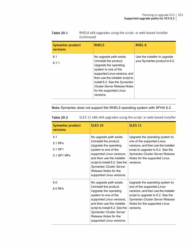
Table 20-1 RHEL6 x64 upgrades using the script- or web-based installer(continued)
RHEL 6RHEL5Symantec productversions
Use the installer to upgradeyour Symantec product to 6.2.
No upgrade path exists.Uninstall the product.Upgrade the operatingsystem to one of thesupported Linux versions, andthen use the installer script toinstall 6.2. See the SymantecCluster Server Release Notesfor the supported Linuxversions.
6.1
6.1.1
Note: Symantec does not support the RHEL5 operating system with SFHA 6.2.
Table 20-2 SLES 11 x86-x64 upgrades using the script- or web-based installer
SLES 11SLES 10Symantec productversions
Upgrade the operating system toone of the supported Linuxversions, and then use the installerscript to upgrade to 6.2. See theSymantec Cluster Server ReleaseNotes for the supported Linuxversions.
No upgrade path exists.Uninstall the product.Upgrade the operatingsystem to one of thesupported Linux versions,and then use the installerscript to install 6.2. See theSymantec Cluster ServerRelease Notes for thesupported Linux versions.
5.1
5.1 RPx
5.1 SP1
5.1 SP1 RPx
Upgrade the operating system toone of the supported Linuxversions, and then use the installerscript to upgrade to 6.2. See theSymantec Cluster Server ReleaseNotes for the supported Linuxversions.
No upgrade path exists.Uninstall the product.Upgrade the operatingsystem to one of thesupported Linux versions,and then use the installerscript to install 6.2. See theSymantec Cluster ServerRelease Notes for thesupported Linux versions.
6.0
6.0 RPx
353Planning to upgrade VCSSupported upgrade paths for VCS 6.2

Table 20-2 SLES 11 x86-x64 upgrades using the script- or web-based installer(continued)
SLES 11SLES 10Symantec productversions
Upgrade the operating system toone of the supported Linuxversions, and then use the installerscript to upgrade to 6.2. See theSymantec Cluster Server ReleaseNotes for the supported Linuxversions.
No upgrade path exists.Uninstall the product.Upgrade the operatingsystem to one of thesupported Linux versions,and then use the installerscript to install 6.2. See theSymantec Cluster ServerRelease Notes for thesupported Linux versions.
6.0.1
6.0.2
6.0.3
6.0.5
Use the installer to upgrade to 6.2.N/A6.0.4
6.1
6.1.1
354Planning to upgrade VCSSupported upgrade paths for VCS 6.2
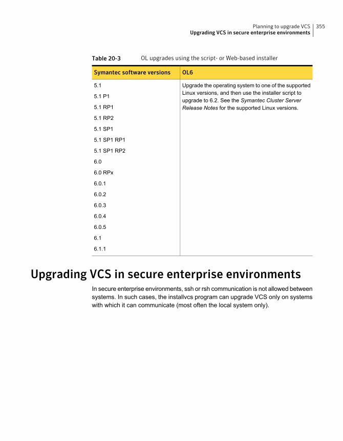
Table 20-3 OL upgrades using the script- or Web-based installer
OL6Symantec software versions
Upgrade the operating system to one of the supportedLinux versions, and then use the installer script toupgrade to 6.2. See the Symantec Cluster ServerRelease Notes for the supported Linux versions.
5.1
5.1 P1
5.1 RP1
5.1 RP2
5.1 SP1
5.1 SP1 RP1
5.1 SP1 RP2
6.0
6.0 RPx
6.0.1
6.0.2
6.0.3
6.0.4
6.0.5
6.1
6.1.1
Upgrading VCS in secure enterprise environmentsIn secure enterprise environments, ssh or rsh communication is not allowed betweensystems. In such cases, the installvcs program can upgrade VCS only on systemswith which it can communicate (most often the local system only).
355Planning to upgrade VCSUpgrading VCS in secure enterprise environments

ToupgradeVCS in secure enterprise environmentswithno rshor ssh communication
1 Run the installvcs program on each node to upgrade the cluster to VCS 6.2.
On each node, the installvcs program updates the configuration, stops thecluster, and then upgrades VCS on the node. The program also generates acluster UUID on the node. Each node may have a different cluster UUID at thispoint.
2 Start VCS on the first node.
# hastart
VCS generates the cluster UUID on this node. Run the following command todisplay the cluster UUID on the local node:
# /opt/VRTSvcs/bin/uuidconfig.pl -clus -display systemname
3 On each of the other nodes, perform the following steps:
■ Set the value of the VCS_HOST environment variable to the name of thefirst node.
■ Display the value of the CID attribute that stores the cluster UUID value:
# haclus -value CID
■ Copy the output of the CID attribute to the file /etc/vx/.uuids/clusuuid.
■ Update the VCS_HOST environment variable to remove the set value.
■ Start VCS.The node must successfully join the already running nodes in the cluster.See “Verifying LLT, GAB, and cluster operation” on page 424.
Considerations for upgrading secure VCS 5.x clustersto VCS 6.2
When you upgrade a secure VCS 5.x cluster to VCS 6.2, the upgrade does notmigrate the old broker configuration to the new broker because of the change inarchitecture. Both the old broker (/opt/VRTSat/bin/vxatd) and new broker(/opt/VRTSvcs/bin/vcsauth/vcsauthserver/bin/vcsauthserver) continue torun. In such a scenario, you must consider the following:
■ The HA commands that you run in VCS 6.2 are processed by the new brokerby default. To ensure that the HA commands are processed by the old broker,set the VCS_REMOTE_BROKER environment variable as follows:
356Planning to upgrade VCSConsiderations for upgrading secure VCS 5.x clusters to VCS 6.2
# export VCS_REMOTE_BROKER=localhost IP,2821
See “About enabling LDAP authentication for clusters that run in secure mode”on page 409.
■ VCS 6.2 does not prompt non-root users who run HA commands for passwords.In 5.x, non-root users required a password to run HA commands. If you wantnon-root users to enter passwords before they run HA commands, set theVCS_DOMAINTYPE environment variable to unixpwd.
■ Trust relationships are not migrated during the upgrade. If you had configuredsecure GCO or secure steward, ensure that trust relationships are recreatedbetween the clusters and the steward.See “Setting up trust relationships for your VCS cluster” on page 143.
When the old broker is not used anymore, you can delete the old VRTSat RPM.
Considerations for upgrading VCS to 6.2 on systemsconfigured with an Oracle resource
If you plan to upgrade VCS running on systems configured with an Oracle resource,set the MonitorOption attribute to 0 (zero) before you start the upgrade. If you usethe product installer for the rolling upgrade, it sets the MonitorOption to 0 throughits scripts. In a manual upgrade, the MonitorOption value must be set to 0 usingthe hares command. When the upgrade is complete, invoke the build_oraapi.sh
script, and then set the MonitorOption to 1 to enable the Oracle health check.
For more information on enabling the Oracle health check, see the Symantec ClusterServer Agent for Oracle Installation and Configuration Guide.
Considerations for upgrading secure VCS clusters toVCS 6.2
1. When you upgrade a secure VCS cluster to VCS 6.2, you need to configureone of the following attributes to enable guest access to the cluster.
■ DefaultGuestAccess: Set the value of this attribute to 1 to enable guestaccess for any authenticated user.
■ GuestGroups: This attribute contains of list of user groups who have readaccess to the cluster. Configure this attribute to control the guest accessto the cluster.
357Planning to upgrade VCSConsiderations for upgrading VCS to 6.2 on systems configured with an Oracle resource
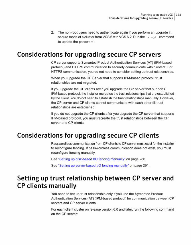
2. The non-root users need to authenticate again if you perform an upgrade insecure mode of a cluster from VCS 6.x to VCS 6.2. Run the halogin commandto update the password.
Considerations for upgrading secure CP serversCP server supports Symantec Product Authentication Services (AT) (IPM-basedprotocol) and HTTPS communication to securely communicate with clusters. ForHTTPS communication, you do not need to consider setting up trust relationships.
When you upgrade the CP Server that supports IPM-based protocol, trustrelationships are not migrated.
If you upgrade the CP clients after you upgrade the CP server that supportsIPM-based protocol, the installer recreates the trust relationships that are establishedby the client. You do not need to establish the trust relationships manually. However,the CP server and CP clients cannot communicate with each other till trustrelationships are established.
If you do not upgrade the CP clients after you upgrade the CP server that supportsIPM-based protocol, you must recreate the trust relationships between the CPserver and CP clients.
Considerations for upgrading secure CP clientsPasswordless communication from CP clients to CP server must exist for the installerto reconfigure fencing. If passwordless communication does not exist, you mustreconfigure fencing manually.
See “Setting up disk-based I/O fencing manually” on page 286.
See “Setting up server-based I/O fencing manually” on page 291.
Setting up trust relationship between CP server andCP clients manually
You need to set up trust relationship only if you use the Symantec ProductAuthentication Services (AT) (IPM-based protocol) for communication between CPservers and CP server clients.
For each client cluster on release version 6.0 and later, run the following commandon the CP server:
358Planning to upgrade VCSConsiderations for upgrading secure CP servers
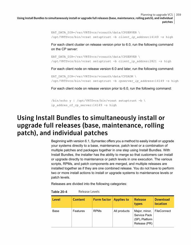
EAT_DATA_DIR=/var/VRTSvcs/vcsauth/data/CPSERVER \
/opt/VRTSvcs/bin/vcsat setuptrust -b client_ip_addres:14149 -s high
For each client cluster on release version prior to 6.0, run the following commandon the CP server:
EAT_DATA_DIR=/var/VRTSvcs/vcsauth/data/CPSERVER \
/opt/VRTSvcs/bin/vcsat setuptrust -b client_ip_addres:2821 -s high
For each client node on release version 6.0 and later, run the following command:
EAT_DATA_DIR=/var/VRTSvcs/vcsauth/data/CPSADM \
/opt/VRTSvcs/bin/vcsat setuptrust -b cpserver_ip_address:14149 -s high
For each client node on release version prior to 6.0, run the following command:
/bin/echo y | /opt/VRTSvcs/bin/vcsat setuptrust -b \
ip_addres_of_cp_server:14149 -s high
Using Install Bundles to simultaneously install orupgrade full releases (base, maintenance, rollingpatch), and individual patches
Beginning with version 6.1, Symantec offers you a method to easily install or upgradeyour systems directly to a base, maintenance, patch level or a combination ofmultiple patches and packages together in one step using Install Bundles. WithInstall Bundles, the installer has the ability to merge so that customers can installor upgrade directly to maintenance or patch levels in one execution. The variousscripts, RPMs, and patch components are merged, and multiple releases areinstalled together as if they are one combined release. You do not have to performtwo or more install actions to install or upgrade systems to maintenance levels orpatch levels.
Releases are divided into the following categories:
Table 20-4 Release Levels
Downloadlocation
Releasetypes
Applies toForm factorContentLevel
FileConnectMajor, minor,Service Pack(SP), PlatformRelease (PR)
All productsRPMsFeaturesBase
359Planning to upgrade VCSUsing Install Bundles to simultaneously install or upgrade full releases (base,maintenance, rolling patch), and individual
patches

Table 20-4 Release Levels (continued)
Downloadlocation
Releasetypes
Applies toForm factorContentLevel
SymantecOperationsReadinessTools (SORT)
MaintenanceRelease(MR), RollingPatch (RP)
All productsRPMsFixes, newfeatures
Maintenance
SORT,Support site
P-Patch,Private Patch,Public patch
Singleproduct
RPMsFixesPatch
When you install or upgrade using Install Bundles:
■ SFHA products are discovered and assigned as a single version to themaintenance level. Each system can also have one or more patches applied.
■ Base releases are accessible from FileConnect that requires customer serialnumbers. Maintenance and patch releases can be automatically downloadedfrom SORT. You can download them from the SORT website manually or usethe deploy_sfha script.
■ Patches can be installed using automated installers from the 6.0.1 version orlater.
■ Patches can now be detected to prevent upgrade conflict. Patch releases arenot offered as a combined release. They are only available from SymantecTechnical Support on a need basis.
You can use the -base_path and -patch_path options to import installation codefrom multiple releases. You can find RPMs and patches from different media paths,and merge RPM and patch definitions for multiple releases. You can use theseoptions to use new task and phase functionality to correctly perform requiredoperations for each release component. You can install the RPMs and patches indefined phases using these options, which helps you when you want to perform asingle start or stop process and perform pre and post operations for all level in asingle operation.
Four possible methods of integration exist. All commands must be executed fromthe highest base or maintenance level install script.
For example:
1. Base + maintenance:
This integration method can be used when you install or upgrade from a lowerversion to 6.2.1.
360Planning to upgrade VCSUsing Install Bundles to simultaneously install or upgrade full releases (base,maintenance, rolling patch), and individual
patches
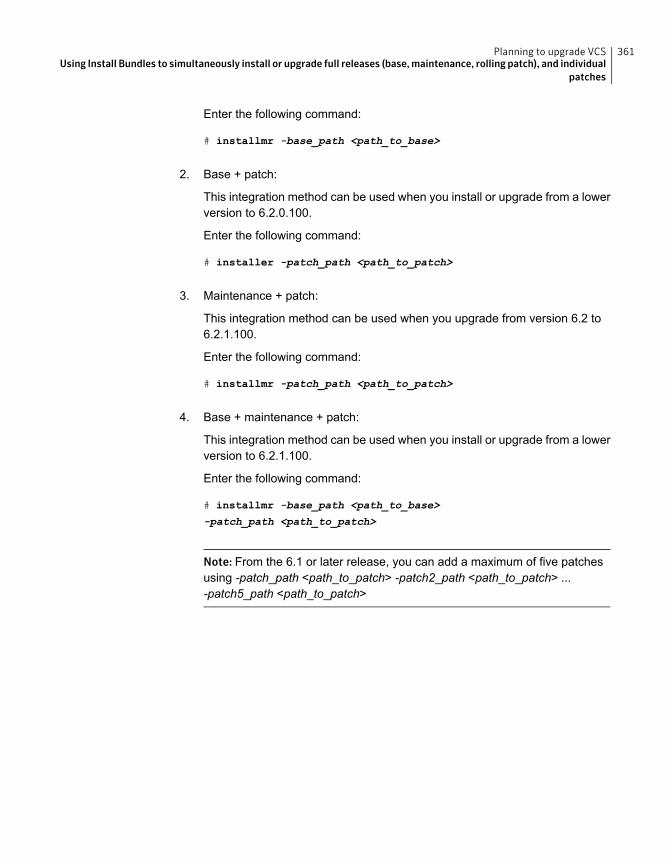
Enter the following command:
# installmr -base_path <path_to_base>
2. Base + patch:
This integration method can be used when you install or upgrade from a lowerversion to 6.2.0.100.
Enter the following command:
# installer -patch_path <path_to_patch>
3. Maintenance + patch:
This integration method can be used when you upgrade from version 6.2 to6.2.1.100.
Enter the following command:
# installmr -patch_path <path_to_patch>
4. Base + maintenance + patch:
This integration method can be used when you install or upgrade from a lowerversion to 6.2.1.100.
Enter the following command:
# installmr -base_path <path_to_base>
-patch_path <path_to_patch>
Note: From the 6.1 or later release, you can add a maximum of five patchesusing -patch_path <path_to_patch> -patch2_path <path_to_patch> ...-patch5_path <path_to_patch>
361Planning to upgrade VCSUsing Install Bundles to simultaneously install or upgrade full releases (base,maintenance, rolling patch), and individual
patches
Performing a typical VCSupgrade using the installer
This chapter includes the following topics:
■ Before upgrading VCS using the script-based or web-based installer
■ Upgrading VCS using the script-based installer
■ Upgrading VCS using the web-based installer
Before upgrading VCS using the script-based orweb-based installer
As a result of OS upgrade, if VCS is not in running state before upgrade, the installerdoes not start VCS after the upgrade is completed. You need to manually start itor restart the cluster nodes. Before you upgrade VCS, you first need to removedeprecated resource types and modify changed values.
To prepare to upgrade to VCS 6.2, make sure that all non-global zones are bootedand in the running state before you install or upgrade the VCS packages in theglobal zone. If the non-global zones are not mounted and running at the time ofupgrade, you must upgrade each package in each non-global zone manually.
Upgrading VCS using the script-based installerYou can use the product installer to upgrade VCS.
21Chapter
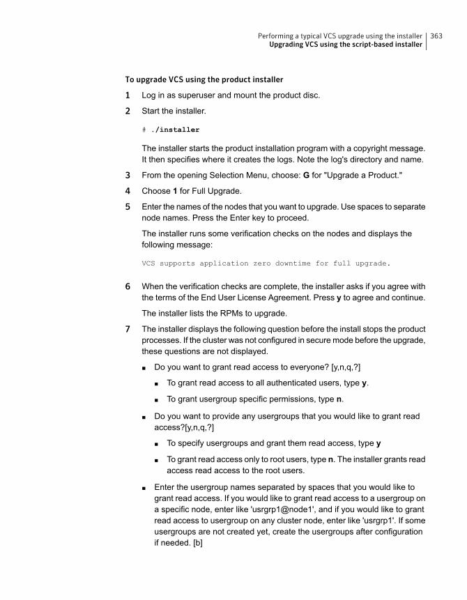
To upgrade VCS using the product installer
1 Log in as superuser and mount the product disc.
2 Start the installer.
# ./installer
The installer starts the product installation program with a copyright message.It then specifies where it creates the logs. Note the log's directory and name.
3 From the opening Selection Menu, choose: G for "Upgrade a Product."
4 Choose 1 for Full Upgrade.
5 Enter the names of the nodes that you want to upgrade. Use spaces to separatenode names. Press the Enter key to proceed.
The installer runs some verification checks on the nodes and displays thefollowing message:
VCS supports application zero downtime for full upgrade.
6 When the verification checks are complete, the installer asks if you agree withthe terms of the End User License Agreement. Press y to agree and continue.
The installer lists the RPMs to upgrade.
7 The installer displays the following question before the install stops the productprocesses. If the cluster was not configured in secure mode before the upgrade,these questions are not displayed.
■ Do you want to grant read access to everyone? [y,n,q,?]
■ To grant read access to all authenticated users, type y.
■ To grant usergroup specific permissions, type n.
■ Do you want to provide any usergroups that you would like to grant readaccess?[y,n,q,?]
■ To specify usergroups and grant them read access, type y
■ To grant read access only to root users, type n. The installer grants readaccess read access to the root users.
■ Enter the usergroup names separated by spaces that you would like togrant read access. If you would like to grant read access to a usergroup ona specific node, enter like 'usrgrp1@node1', and if you would like to grantread access to usergroup on any cluster node, enter like 'usrgrp1'. If someusergroups are not created yet, create the usergroups after configurationif needed. [b]
363Performing a typical VCS upgrade using the installerUpgrading VCS using the script-based installer
8 The installer asks if you want to stop VCS processes. Press the Enter key tocontinue.
The installer stops VCS processes, uninstalls RPMs, installs or upgrades RPMs,and configures VCS.
The installer lists the nodes that Symantec recommends you restart.
9 The installer asks if you would like to send the information about this installationto Symantec to help improve installation in the future. Enter your response.
The installer displays the location of log files, summary file, and response file.
10 If you want to upgrade CP server systems that use VCS or SFHA to VCS 6.2,make sure that you first upgrade all application clusters to version VCS 6.2.Then, upgrade VCS or SFHA on the CP server systems.
For instructions to upgrade VCS or SFHA, see the Symantec Cluster ServerInstallation Guide or the Storage Foundation and High Availability InstallationGuide.
If you are upgrading from 4.x, you may need to create new VCS accounts if youused native OS accounts.
Upgrading VCS using the web-based installerThis section describes upgrading VCS with the web-based installer. The installerdetects and upgrades the product that is currently installed on the specified systemor systems.
To upgrade VCS
1 Perform the required steps to save any data that you want to preserve. Forexample, make configuration file backups.
2 If you want to upgrade a high availability (HA) product, take all service groupsoffline. List all service groups:
# /opt/VRTSvcs/bin/hagrp -list
For each service group listed, take it offline:
# /opt/VRTSvcs/bin/hagrp -offline service_group -any
3 Start the web-based installer.
See “Starting the web-based installer” on page 189.
364Performing a typical VCS upgrade using the installerUpgrading VCS using the web-based installer
4 On the Select a task and a product page, select Upgrade a Product from theTask drop-down menu.
The product is discovered once you specify the system. Click Next.
5 Indicate the systems on which to upgrade. Enter one or more system names,separated by spaces. Click Next.
6 Installer detects the product that is installed on the specified system. It showsthe cluster information and lets you confirm if you want to perform upgrade onthe cluster. Select Yes and click Next.
7 On the License agreement page, select whether you accept the terms of theEnd User License Agreement (EULA). To continue, select Yes I agree andclick Next.
8 Click Next to complete the upgrade.
After the upgrade completes, the installer displays the location of the log andsummary files. If required, view the files to confirm the installation status.
9 The installer displays the following question before the install stops the productprocesses. If the cluster was not configured in secure mode before the upgrade,these questions are not displayed.
■ Do you want to grant read access to everyone? [y,n,q,?]
■ To grant read access to all authenticated users, type y.
■ To grant more usergroup specific permissions, type n.
■ Do you want to provide any usergroups that you would like to grant readaccess?[y,n,q,?]
■ To specify usergroups and grant them read access, type y.
■ To grant read access only to root users, type n. The installer grants readaccess read access to the root users.
■ Enter the usergroup names separated by spaces that you would like togrant read access. If you would like to grant read access to a usergroup ona specific node, enter like 'usrgrp1@node1', and if you would like to grantread access to usergroup on any cluster node, enter like 'usrgrp1'. If someusergroups are not created yet, create the usergroups after configurationif needed. [b]
10 If you are prompted to restart the systems, enter the following restart command:
# /sbin/shutdown -r now
365Performing a typical VCS upgrade using the installerUpgrading VCS using the web-based installer

11 After the upgrade, if the product is not configured, the web-based installer asks:"Do you want to configure this product?" If the product is already configured,it does not ask any questions.
12 Click Finish. The installer prompts you for another task.
13 If you want to upgrade application clusters that use VCS or SFHA to 6.2, makesure that you upgrade VCS or SFHA on the CP server systems. Then, upgradeall application clusters to version 6.2. For instructions to upgrade VCS or SFHA,see the VCS or SFHA Installation Guide.
366Performing a typical VCS upgrade using the installerUpgrading VCS using the web-based installer

Performing an onlineupgrade
This chapter includes the following topics:
■ Limitations of online upgrade
■ Upgrading VCS online using the script-based installer
■ Upgrading VCS online using the web-based installer
Limitations of online upgrade■ Online upgrade is available only for VCS and ApplicationHA. If you have Storage
Foundation, SFHA, SFCFSHA, or any other solution with VxVM and VxFSinstalled, then the online upgrade process will not be supported.
■ The non-Symantec applications running on the node have zero down time duringthe online upgrade.
■ VCS does not monitor the applications when online upgrade is in progress.
■ For upgrades from VCS versions lower than 6.1, upgrade the CP server beforeperforming the online upgrade.
See “Supported upgrade paths for VCS 6.2” on page 351.
See “Upgrading VCS online using the script-based installer” on page 368.
See “Upgrading VCS online using the web-based installer” on page 369.
22Chapter

Upgrading VCSonline using the script-based installerYou can use the product installer to upgrade VCS online. The supported upgradepaths are same as those for the script-based installer.
See “Supported upgrade paths for VCS 6.2” on page 351.
To upgrade VCS online using the product installer
1 Log in as superuser and mount the product disc.
2 Start the installer.
# ./installer
The installer starts the product installation program with a copyright message.It then specifies where it creates the logs.
Note the directory name and path where the logs get stored.
3 From the opening Selection Menu, choose: G for "Upgrade a Product."
The system prompts you to select the method by which you want to upgradethe product.
4 Choose 3 for Online Upgrade from the upgrade options.
5 After selecting the online upgrade method, enter any one system name fromthe cluster on which you want to perform the online upgrade.
Even if you specify a single node from the cluster, the installer asks whetheryou want to perform online upgrade of VCS on the entire cluster, keeping yourapplications online. After you enter the system name, the installer performssome verification checks and asks the following question:
Online upgrade supports application zero downtime.
Would you like to perform online upgrade on the
whole cluster? [y,n,q](y)
6 Enter y to initiate the online upgrade.
Note: You can either exit the installer with the option q or cancel the upgradeusing n and select any other cluster to upgrade at this step.
The installer runs some verification checks on the nodes and subsequentlyasks if you agree with the terms of the End User License Agreement.
7 Enter y to agree and continue.
The installer lists the RPMs that will be upgraded.
368Performing an online upgradeUpgrading VCS online using the script-based installer
8 The installer displays the following question before the install stops the productprocesses. If the cluster was not configured in secure mode before the upgrade,these questions are not displayed.
■ Do you want to grant read access to everyone? [y,n,q,?]
■ To grant read access to all authenticated users, type y.
■ To grant usergroup specific permissions, type n.
■ Do you want to provide any usergroups that you would like to grant readaccess?[y,n,q,?]
■ To specify usergroups and grant them read access, type y
■ To grant read access only to root users, type n. The installer grants readaccess read access to the root users.
■ Enter the usergroup names separated by spaces that you would like togrant read access. If you would like to grant read access to a usergroup ona specific node, enter like 'usrgrp1@node1', and if you would like to grantread access to usergroup on any cluster node, enter like 'usrgrp1'. If someusergroups are not created yet, create the usergroups after configurationif needed. [b]
9 The installer asks if you want to stop VCS processes. Enter y to stop the VCSprocess.
It stops the VCS processes, uninstalls RPMs, reinstalls or upgrade RPMs,again configures VCS, and starts the processes.
10 The installer asks if you want to stop VCS processes. Enter y to stop the VCSprocess.
It stops the VCS processes, uninstalls RPMs, reinstalls or upgrade RPMs,again configures VCS, and starts the processes.
Upgrading VCS online using the web-based installerThis section describes upgrading VCS online with the web-based installer. Theinstaller detects and upgrades the product that is currently installed on the specifiedsystem or systems. The web-based installer upgrades VCS without stopping yourapplications. The supported upgrade paths are same as those for the web-basedinstaller upgrade.
See “Supported upgrade paths for VCS 6.2” on page 351.
369Performing an online upgradeUpgrading VCS online using the web-based installer
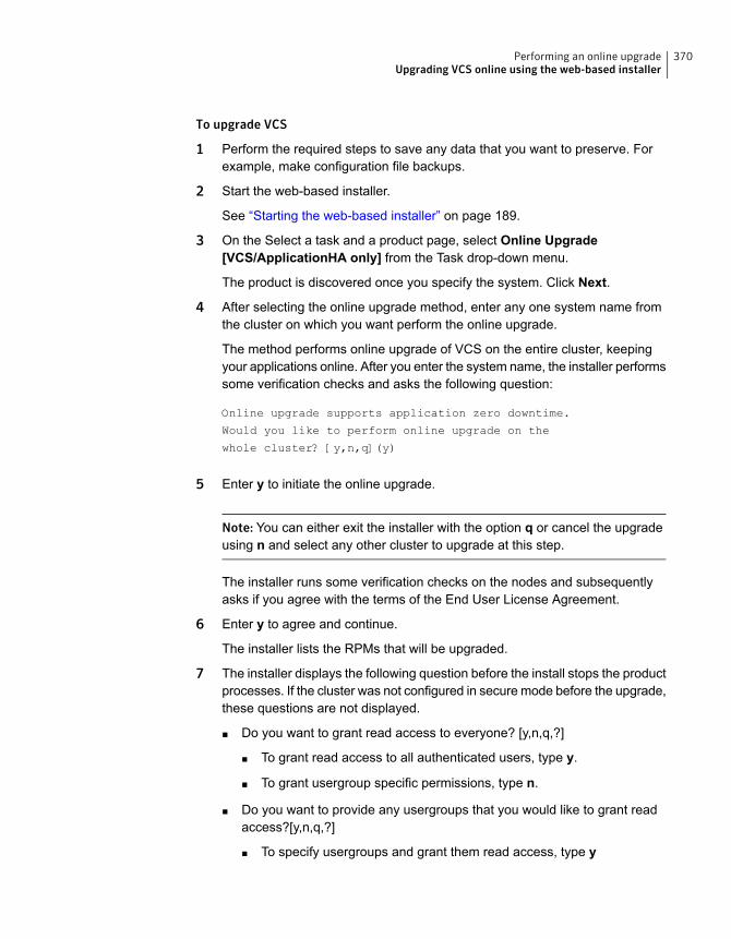
To upgrade VCS
1 Perform the required steps to save any data that you want to preserve. Forexample, make configuration file backups.
2 Start the web-based installer.
See “Starting the web-based installer” on page 189.
3 On the Select a task and a product page, select Online Upgrade[VCS/ApplicationHA only] from the Task drop-down menu.
The product is discovered once you specify the system. Click Next.
4 After selecting the online upgrade method, enter any one system name fromthe cluster on which you want perform the online upgrade.
The method performs online upgrade of VCS on the entire cluster, keepingyour applications online. After you enter the system name, the installer performssome verification checks and asks the following question:
Online upgrade supports application zero downtime.
Would you like to perform online upgrade on the
whole cluster? [y,n,q](y)
5 Enter y to initiate the online upgrade.
Note: You can either exit the installer with the option q or cancel the upgradeusing n and select any other cluster to upgrade at this step.
The installer runs some verification checks on the nodes and subsequentlyasks if you agree with the terms of the End User License Agreement.
6 Enter y to agree and continue.
The installer lists the RPMs that will be upgraded.
7 The installer displays the following question before the install stops the productprocesses. If the cluster was not configured in secure mode before the upgrade,these questions are not displayed.
■ Do you want to grant read access to everyone? [y,n,q,?]
■ To grant read access to all authenticated users, type y.
■ To grant usergroup specific permissions, type n.
■ Do you want to provide any usergroups that you would like to grant readaccess?[y,n,q,?]
■ To specify usergroups and grant them read access, type y
370Performing an online upgradeUpgrading VCS online using the web-based installer

■ To grant read access only to root users, type n. The installer grants readaccess read access to the root users.
■ Enter the usergroup names separated by spaces that you would like togrant read access. If you would like to grant read access to a usergroup ona specific node, enter like 'usrgrp1@node1', and if you would like to grantread access to usergroup on any cluster node, enter like 'usrgrp1'. If someusergroups are not created yet, create the usergroups after configurationif needed. [b]
8 The installer asks if you want to stop VCS processes. Enter y to stop the VCSprocess.
It stops the VCS processes, uninstalls RPMs, reinstalls or upgrade RPMs,again configures VCS, and starts the processes.
371Performing an online upgradeUpgrading VCS online using the web-based installer
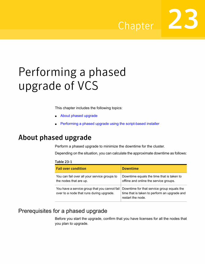
Performing a phasedupgrade of VCS
This chapter includes the following topics:
■ About phased upgrade
■ Performing a phased upgrade using the script-based installer
About phased upgradePerform a phased upgrade to minimize the downtime for the cluster.
Depending on the situation, you can calculate the approximate downtime as follows:
Table 23-1
DowntimeFail over condition
Downtime equals the time that is taken tooffline and online the service groups.
You can fail over all your service groups tothe nodes that are up.
Downtime for that service group equals thetime that is taken to perform an upgrade andrestart the node.
You have a service group that you cannot failover to a node that runs during upgrade.
Prerequisites for a phased upgradeBefore you start the upgrade, confirm that you have licenses for all the nodes thatyou plan to upgrade.
23Chapter
Planning for a phased upgradePlan out the movement of the service groups from node-to-node to minimize thedowntime for any particular service group.
Some rough guidelines follow:
■ Split the cluster into two sub-clusters of equal or near equal size.
■ Split the cluster so that your high priority service groups remain online duringthe upgrade of the first subcluster.
■ Before you start the upgrade, back up the VCS configuration files main.cf andtypes.cf which are in the /etc/VRTSvcs/conf/config/ directory.
■ Before you start the upgrade make sure that all the disk groups have the latestbackup of configuration files in the /etc/vx/cbr/bk directory. If not, then runthe following command to take the latest backup.
# /etc/vx/bin/vxconfigbackup -| [dir] [dgname|dgid]
Phased upgrade limitationsThe following limitations primarily describe not to tamper with configurations orservice groups during the phased upgrade:
■ While you perform the upgrades, do not start any modules.
■ When you start the installer, only select VCS.
■ While you perform the upgrades, do not add or remove service groups to anyof the nodes.
■ After you upgrade the first half of your cluster (the first subcluster), you need toset up password-less SSH or RSH. Create the connection between an upgradednode in the first subcluster and a node from the other subcluster. The node fromthe other subcluster is where you plan to run the installer and also plan toupgrade.
■ Depending on your configuration, you may find that you cannot upgrade multiplenodes at the same time. You may only be able to upgrade one node at a time.
■ For very large clusters, you might have to repeat these steps multiple times toupgrade your cluster.
Phased upgrade exampleIn this example, you have a secure cluster that you have configured to run on fournodes: node01, node02, node03, and node04. You also have four service groups:
373Performing a phased upgrade of VCSAbout phased upgrade
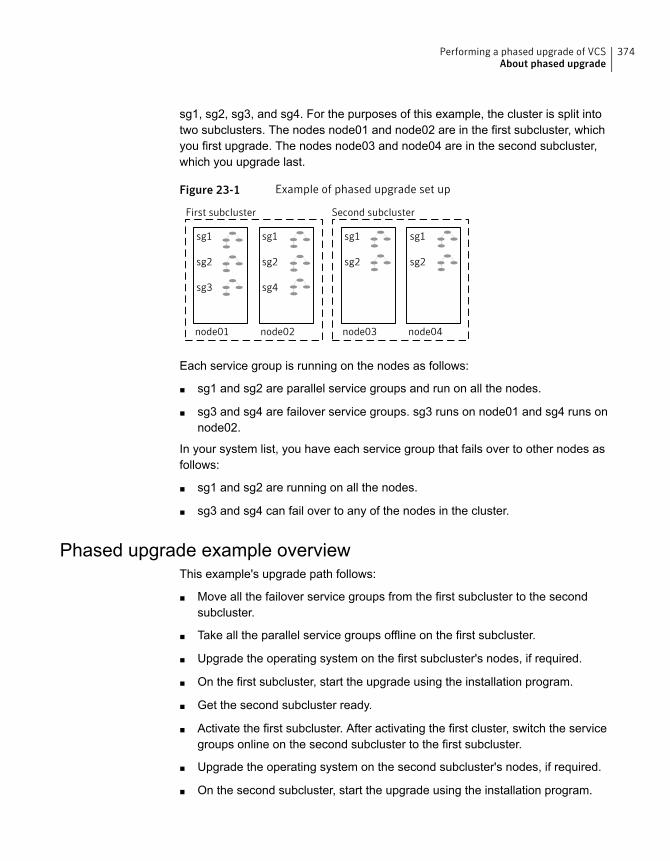
sg1, sg2, sg3, and sg4. For the purposes of this example, the cluster is split intotwo subclusters. The nodes node01 and node02 are in the first subcluster, whichyou first upgrade. The nodes node03 and node04 are in the second subcluster,which you upgrade last.
Figure 23-1 Example of phased upgrade set up
node01 node04node03node02
First subcluster Second subcluster
sg1
sg2
sg3
sg1
sg2
sg4
sg1
sg2
sg1
sg2
Each service group is running on the nodes as follows:
■ sg1 and sg2 are parallel service groups and run on all the nodes.
■ sg3 and sg4 are failover service groups. sg3 runs on node01 and sg4 runs onnode02.
In your system list, you have each service group that fails over to other nodes asfollows:
■ sg1 and sg2 are running on all the nodes.
■ sg3 and sg4 can fail over to any of the nodes in the cluster.
Phased upgrade example overviewThis example's upgrade path follows:
■ Move all the failover service groups from the first subcluster to the secondsubcluster.
■ Take all the parallel service groups offline on the first subcluster.
■ Upgrade the operating system on the first subcluster's nodes, if required.
■ On the first subcluster, start the upgrade using the installation program.
■ Get the second subcluster ready.
■ Activate the first subcluster. After activating the first cluster, switch the servicegroups online on the second subcluster to the first subcluster.
■ Upgrade the operating system on the second subcluster's nodes, if required.
■ On the second subcluster, start the upgrade using the installation program.
374Performing a phased upgrade of VCSAbout phased upgrade
■ Activate the second subcluster.
See “Performing a phased upgrade using the script-based installer” on page 375.
Performing a phased upgrade using the script-basedinstaller
This section explains how to perform a phased upgrade of VCS on four nodes withfour service groups. Note that in this scenario, VCS and the service groups cannotstay online on the second subcluster during the upgrade of the second subcluster.Do not add, remove, or change resources or service groups on any nodes duringthe upgrade. These changes are likely to get lost after the upgrade.
An example of a phased upgrade follows. It illustrates the steps to perform a phasedupgrade. The example makes use of a secure VCS cluster.
You can perform a phased upgrade from VCS 5.1 or other supported previousversions to VCS 6.2.
See “About phased upgrade” on page 372.
See “Phased upgrade example” on page 373.
Moving the service groups to the second subclusterPerform the following steps to establish the service group's status and to switchthe service groups.
375Performing a phased upgrade of VCSPerforming a phased upgrade using the script-based installer
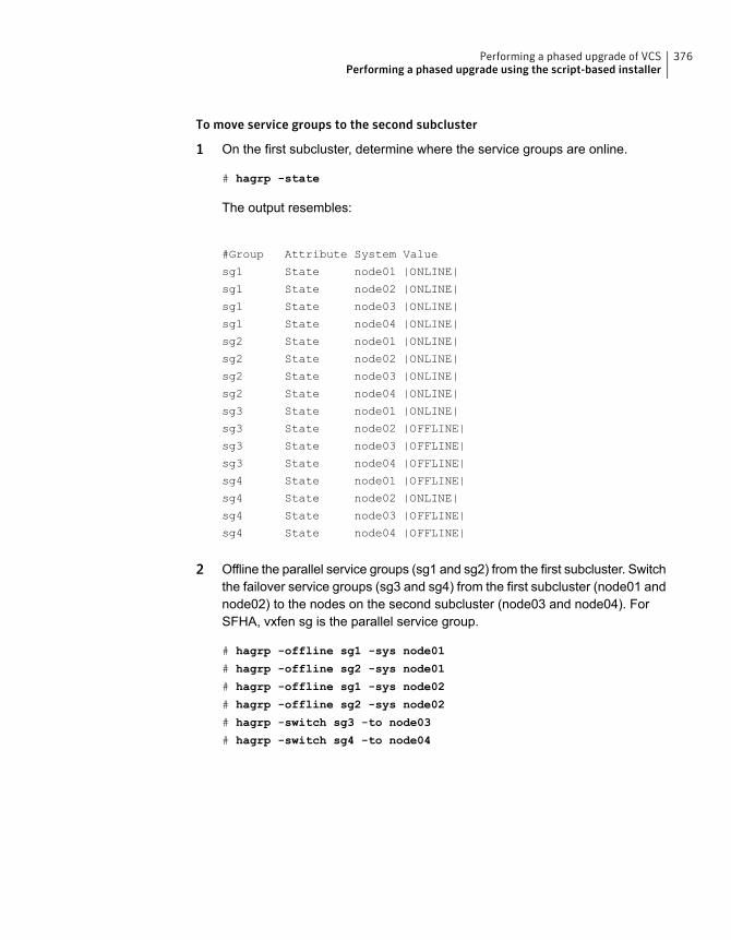
To move service groups to the second subcluster
1 On the first subcluster, determine where the service groups are online.
# hagrp -state
The output resembles:
#Group Attribute System Value
sg1 State node01 |ONLINE|
sg1 State node02 |ONLINE|
sg1 State node03 |ONLINE|
sg1 State node04 |ONLINE|
sg2 State node01 |ONLINE|
sg2 State node02 |ONLINE|
sg2 State node03 |ONLINE|
sg2 State node04 |ONLINE|
sg3 State node01 |ONLINE|
sg3 State node02 |OFFLINE|
sg3 State node03 |OFFLINE|
sg3 State node04 |OFFLINE|
sg4 State node01 |OFFLINE|
sg4 State node02 |ONLINE|
sg4 State node03 |OFFLINE|
sg4 State node04 |OFFLINE|
2 Offline the parallel service groups (sg1 and sg2) from the first subcluster. Switchthe failover service groups (sg3 and sg4) from the first subcluster (node01 andnode02) to the nodes on the second subcluster (node03 and node04). ForSFHA, vxfen sg is the parallel service group.
# hagrp -offline sg1 -sys node01
# hagrp -offline sg2 -sys node01
# hagrp -offline sg1 -sys node02
# hagrp -offline sg2 -sys node02
# hagrp -switch sg3 -to node03
# hagrp -switch sg4 -to node04
376Performing a phased upgrade of VCSPerforming a phased upgrade using the script-based installer
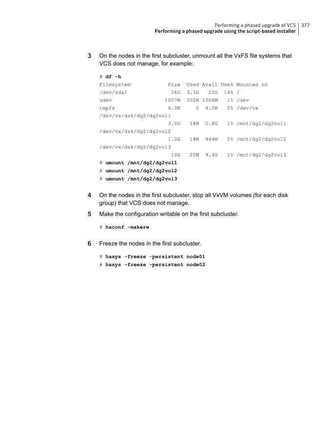
3 On the nodes in the first subcluster, unmount all the VxFS file systems thatVCS does not manage, for example:
# df -h
Filesystem Size Used Avail Use% Mounted on
/dev/sda1 26G 3.3G 22G 14% /
udev 1007M 352K 1006M 1% /dev
tmpfs 4.0K 0 4.0K 0% /dev/vx
/dev/vx/dsk/dg2/dg2vol1
3.0G 18M 2.8G 1% /mnt/dg2/dg2vol1
/dev/vx/dsk/dg2/dg2vol2
1.0G 18M 944M 2% /mnt/dg2/dg2vol2
/dev/vx/dsk/dg2/dg2vol3
10G 20M 9.4G 1% /mnt/dg2/dg2vol3
# umount /mnt/dg2/dg2vol1
# umount /mnt/dg2/dg2vol2
# umount /mnt/dg2/dg2vol3
4 On the nodes in the first subcluster, stop all VxVM volumes (for each diskgroup) that VCS does not manage.
5 Make the configuration writable on the first subcluster.
# haconf -makerw
6 Freeze the nodes in the first subcluster.
# hasys -freeze -persistent node01
# hasys -freeze -persistent node02
377Performing a phased upgrade of VCSPerforming a phased upgrade using the script-based installer

7 Dump the configuration and make it read-only.
# haconf -dump -makero
8 Verify that the service groups are offline on the first subcluster that you wantto upgrade.
# hagrp -state
Output resembles:
#Group Attribute System Value
sg1 State node01 |OFFLINE|
sg1 State node02 |OFFLINE|
sg1 State node03 |ONLINE|
sg1 State node04 |ONLINE|
sg2 State node01 |OFFLINE|
sg2 State node02 |OFFLINE|
sg2 State node03 |ONLINE|
sg2 State node04 |ONLINE|
sg3 State node01 |OFFLINE|
sg3 State node02 |OFFLINE|
sg3 State node03 |ONLINE|
sg3 State node04 |OFFLINE|
sg4 State node01 |OFFLINE|
sg4 State node02 |OFFLINE|
sg4 State node03 |OFFLINE|
sg4 State node04 |ONLINE|
Upgrading the operating system on the first subclusterYou can perform the operating system upgrade on the first subcluster, if required.
Before performing operating system upgrade, it is better to prevent LLT from startingautomatically when the node starts. For example, you can do the following:
# mv /etc/llttab /etc/llttab.save
or you can change the /etc/default/llt file by setting LLT_START = 0.
After you finish upgrading the OS, remember to change the LLT configuration toits original configuration.
Refer to the operating system's documentation for more information.
378Performing a phased upgrade of VCSPerforming a phased upgrade using the script-based installer
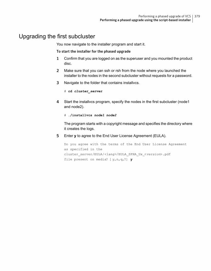
Upgrading the first subclusterYou now navigate to the installer program and start it.
To start the installer for the phased upgrade
1 Confirm that you are logged on as the superuser and you mounted the productdisc.
2 Make sure that you can ssh or rsh from the node where you launched theinstaller to the nodes in the second subcluster without requests for a password.
3 Navigate to the folder that contains installvcs.
# cd cluster_server
4 Start the installvcs program, specify the nodes in the first subcluster (node1and node2).
# ./installvcs node1 node2
The program starts with a copyright message and specifies the directory whereit creates the logs.
5 Enter y to agree to the End User License Agreement (EULA).
Do you agree with the terms of the End User License Agreement
as specified in the
cluster_server/EULA/<lang>/EULA_SFHA_Ux_<version>.pdf
file present on media? [y,n,q,?] y
379Performing a phased upgrade of VCSPerforming a phased upgrade using the script-based installer
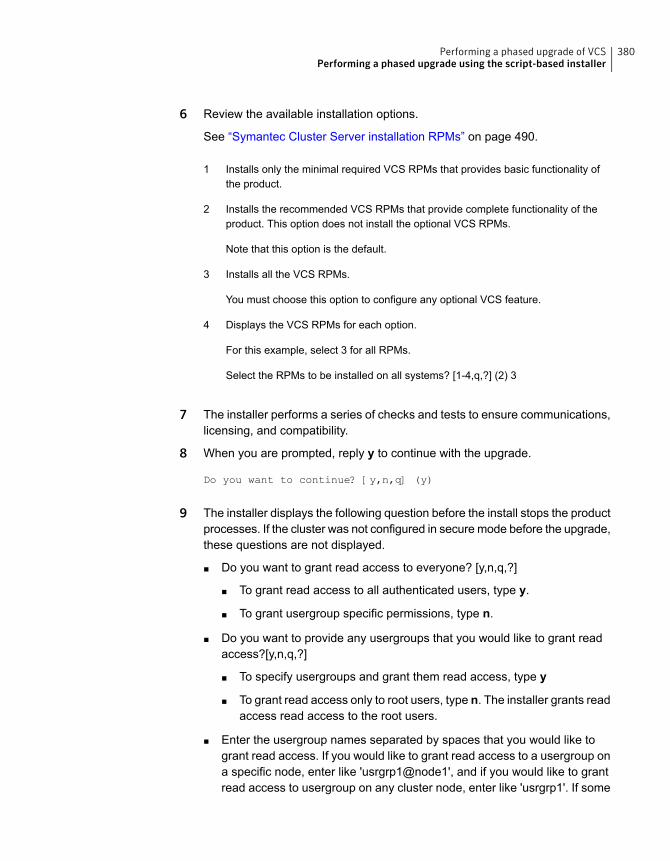
6 Review the available installation options.
See “Symantec Cluster Server installation RPMs” on page 490.
Installs only the minimal required VCS RPMs that provides basic functionality ofthe product.
1
Installs the recommended VCS RPMs that provide complete functionality of theproduct. This option does not install the optional VCS RPMs.
2
Note that this option is the default.
Installs all the VCS RPMs.3
You must choose this option to configure any optional VCS feature.
Displays the VCS RPMs for each option.4
For this example, select 3 for all RPMs.
Select the RPMs to be installed on all systems? [1-4,q,?] (2) 3
7 The installer performs a series of checks and tests to ensure communications,licensing, and compatibility.
8 When you are prompted, reply y to continue with the upgrade.
Do you want to continue? [y,n,q] (y)
9 The installer displays the following question before the install stops the productprocesses. If the cluster was not configured in secure mode before the upgrade,these questions are not displayed.
■ Do you want to grant read access to everyone? [y,n,q,?]
■ To grant read access to all authenticated users, type y.
■ To grant usergroup specific permissions, type n.
■ Do you want to provide any usergroups that you would like to grant readaccess?[y,n,q,?]
■ To specify usergroups and grant them read access, type y
■ To grant read access only to root users, type n. The installer grants readaccess read access to the root users.
■ Enter the usergroup names separated by spaces that you would like togrant read access. If you would like to grant read access to a usergroup ona specific node, enter like 'usrgrp1@node1', and if you would like to grantread access to usergroup on any cluster node, enter like 'usrgrp1'. If some
380Performing a phased upgrade of VCSPerforming a phased upgrade using the script-based installer
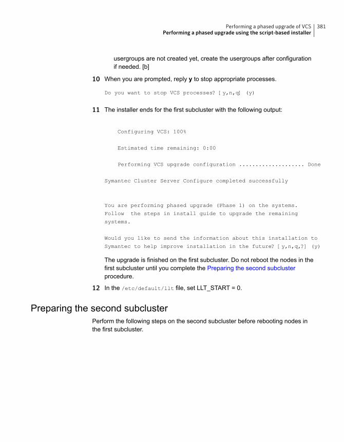
usergroups are not created yet, create the usergroups after configurationif needed. [b]
10 When you are prompted, reply y to stop appropriate processes.
Do you want to stop VCS processes? [y,n,q] (y)
11 The installer ends for the first subcluster with the following output:
Configuring VCS: 100%
Estimated time remaining: 0:00 1 of 1
Performing VCS upgrade configuration .................... Done
Symantec Cluster Server Configure completed successfully
You are performing phased upgrade (Phase 1) on the systems.
Follow the steps in install guide to upgrade the remaining
systems.
Would you like to send the information about this installation to
Symantec to help improve installation in the future? [y,n,q,?] (y)
The upgrade is finished on the first subcluster. Do not reboot the nodes in thefirst subcluster until you complete the Preparing the second subclusterprocedure.
12 In the /etc/default/llt file, set LLT_START = 0.
Preparing the second subclusterPerform the following steps on the second subcluster before rebooting nodes inthe first subcluster.
381Performing a phased upgrade of VCSPerforming a phased upgrade using the script-based installer
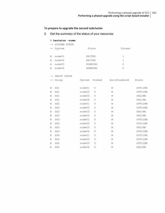
To prepare to upgrade the second subcluster
1 Get the summary of the status of your resources.
# hastatus -summ
-- SYSTEM STATE
-- System State Frozen
A node01 EXITED 1
A node02 EXITED 1
A node03 RUNNING 0
A node04 RUNNING 0
-- GROUP STATE
-- Group System Probed AutoDisabled State
B SG1 node01 Y N OFFLINE
B SG1 node02 Y N OFFLINE
B SG1 node03 Y N ONLINE
B SG1 node04 Y N ONLINE
B SG2 node01 Y N OFFLINE
B SG2 node02 Y N OFFLINE
B SG2 node03 Y N ONLINE
B SG2 node04 Y N ONLINE
B SG3 node01 Y N OFFLINE
B SG3 node02 Y N OFFLINE
B SG3 node03 Y N ONLINE
B SG3 node04 Y N OFFLINE
B SG4 node01 Y N OFFLINE
B SG4 node02 Y N OFFLINE
B SG4 node03 Y N OFFLINE
B SG4 node04 Y N ONLINE
382Performing a phased upgrade of VCSPerforming a phased upgrade using the script-based installer
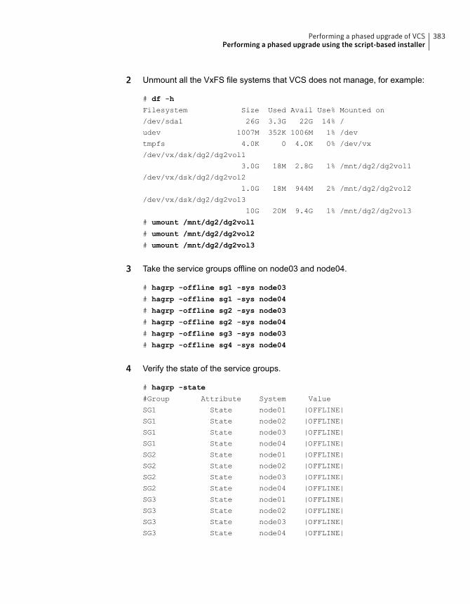
2 Unmount all the VxFS file systems that VCS does not manage, for example:
# df -h
Filesystem Size Used Avail Use% Mounted on
/dev/sda1 26G 3.3G 22G 14% /
udev 1007M 352K 1006M 1% /dev
tmpfs 4.0K 0 4.0K 0% /dev/vx
/dev/vx/dsk/dg2/dg2vol1
3.0G 18M 2.8G 1% /mnt/dg2/dg2vol1
/dev/vx/dsk/dg2/dg2vol2
1.0G 18M 944M 2% /mnt/dg2/dg2vol2
/dev/vx/dsk/dg2/dg2vol3
10G 20M 9.4G 1% /mnt/dg2/dg2vol3
# umount /mnt/dg2/dg2vol1
# umount /mnt/dg2/dg2vol2
# umount /mnt/dg2/dg2vol3
3 Take the service groups offline on node03 and node04.
# hagrp -offline sg1 -sys node03
# hagrp -offline sg1 -sys node04
# hagrp -offline sg2 -sys node03
# hagrp -offline sg2 -sys node04
# hagrp -offline sg3 -sys node03
# hagrp -offline sg4 -sys node04
4 Verify the state of the service groups.
# hagrp -state
#Group Attribute System Value
SG1 State node01 |OFFLINE|
SG1 State node02 |OFFLINE|
SG1 State node03 |OFFLINE|
SG1 State node04 |OFFLINE|
SG2 State node01 |OFFLINE|
SG2 State node02 |OFFLINE|
SG2 State node03 |OFFLINE|
SG2 State node04 |OFFLINE|
SG3 State node01 |OFFLINE|
SG3 State node02 |OFFLINE|
SG3 State node03 |OFFLINE|
SG3 State node04 |OFFLINE|
383Performing a phased upgrade of VCSPerforming a phased upgrade using the script-based installer
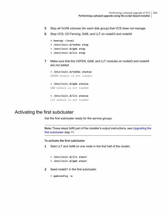
5 Stop all VxVM volumes (for each disk group) that VCS does not manage.
6 Stop VCS, I/O Fencing, GAB, and LLT on node03 and node04.
# hastop -local
# /etc/init.d/vxfen stop
# /etc/init.d/gab stop
# /etc/init.d/llt stop
7 Make sure that the VXFEN, GAB, and LLT modules on node03 and node04are not added.
# /etc/init.d/vxfen status
VXFEN module is not loaded
# /etc/init.d/gab status
GAB module is not loaded
# /etc/init.d/llt status
LLT module is not loaded
Activating the first subclusterGet the first subcluster ready for the service groups.
Note:These steps fulfill part of the installer's output instructions, see Upgrading thefirst subcluster step 11.
To activate the first subcluster
1 Start LLT and GAB on one node in the first half of the cluster..
# /etc/init.d/llt start
# /etc/init.d/gab start
2 Seed node01 in the first subcluster.
# gabconfig -x
384Performing a phased upgrade of VCSPerforming a phased upgrade using the script-based installer
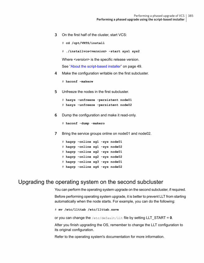
3 On the first half of the cluster, start VCS:
# cd /opt/VRTS/install
# ./installvcs<version> -start sys1 sys2
Where <version> is the specific release version.
See “About the script-based installer” on page 49.
4 Make the configuration writable on the first subcluster.
# haconf -makerw
5 Unfreeze the nodes in the first subcluster.
# hasys -unfreeze -persistent node01
# hasys -unfreeze -persistent node02
6 Dump the configuration and make it read-only.
# haconf -dump -makero
7 Bring the service groups online on node01 and node02.
# hagrp -online sg1 -sys node01
# hagrp -online sg1 -sys node02
# hagrp -online sg2 -sys node01
# hagrp -online sg2 -sys node02
# hagrp -online sg3 -sys node01
# hagrp -online sg4 -sys node02
Upgrading the operating system on the second subclusterYou can perform the operating system upgrade on the second subcluster, if required.
Before performing operating system upgrade, it is better to prevent LLT from startingautomatically when the node starts. For example, you can do the following:
# mv /etc/llttab /etc/llttab.save
or you can change the /etc/default/llt file by setting LLT_START = 0.
After you finish upgrading the OS, remember to change the LLT configuration toits original configuration.
Refer to the operating system's documentation for more information.
385Performing a phased upgrade of VCSPerforming a phased upgrade using the script-based installer
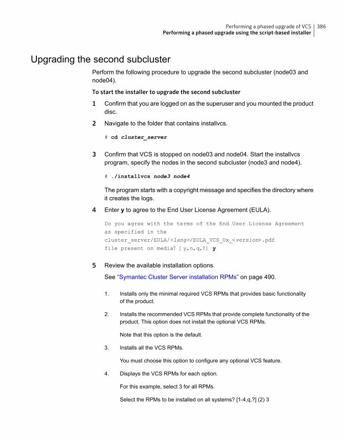
Upgrading the second subclusterPerform the following procedure to upgrade the second subcluster (node03 andnode04).
To start the installer to upgrade the second subcluster
1 Confirm that you are logged on as the superuser and you mounted the productdisc.
2 Navigate to the folder that contains installvcs.
# cd cluster_server
3 Confirm that VCS is stopped on node03 and node04. Start the installvcsprogram, specify the nodes in the second subcluster (node3 and node4).
# ./installvcs node3 node4
The program starts with a copyright message and specifies the directory whereit creates the logs.
4 Enter y to agree to the End User License Agreement (EULA).
Do you agree with the terms of the End User License Agreement
as specified in the
cluster_server/EULA/<lang>/EULA_VCS_Ux_<version>.pdf
file present on media? [y,n,q,?] y
5 Review the available installation options.
See “Symantec Cluster Server installation RPMs” on page 490.
Installs only the minimal required VCS RPMs that provides basic functionalityof the product.
1.
Installs the recommended VCS RPMs that provide complete functionality of theproduct. This option does not install the optional VCS RPMs.
2.
Note that this option is the default.
Installs all the VCS RPMs.3.
You must choose this option to configure any optional VCS feature.
Displays the VCS RPMs for each option.4.
For this example, select 3 for all RPMs.
Select the RPMs to be installed on all systems? [1-4,q,?] (2) 3
386Performing a phased upgrade of VCSPerforming a phased upgrade using the script-based installer
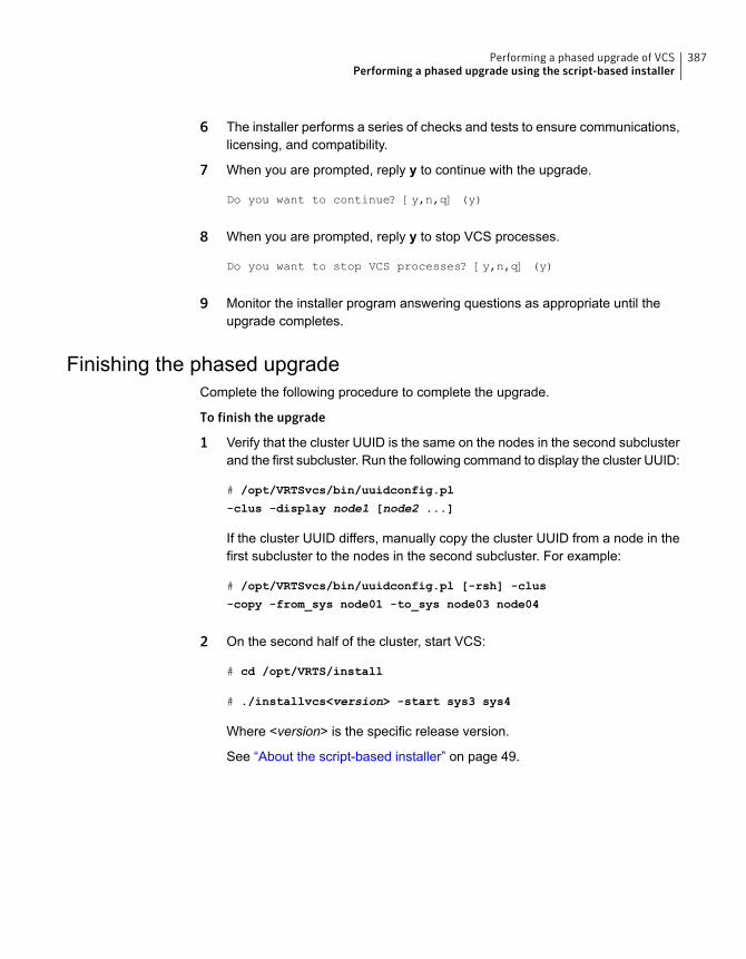
6 The installer performs a series of checks and tests to ensure communications,licensing, and compatibility.
7 When you are prompted, reply y to continue with the upgrade.
Do you want to continue? [y,n,q] (y)
8 When you are prompted, reply y to stop VCS processes.
Do you want to stop VCS processes? [y,n,q] (y)
9 Monitor the installer program answering questions as appropriate until theupgrade completes.
Finishing the phased upgradeComplete the following procedure to complete the upgrade.
To finish the upgrade
1 Verify that the cluster UUID is the same on the nodes in the second subclusterand the first subcluster. Run the following command to display the cluster UUID:
# /opt/VRTSvcs/bin/uuidconfig.pl
-clus -display node1 [node2 ...]
If the cluster UUID differs, manually copy the cluster UUID from a node in thefirst subcluster to the nodes in the second subcluster. For example:
# /opt/VRTSvcs/bin/uuidconfig.pl [-rsh] -clus
-copy -from_sys node01 -to_sys node03 node04
2 On the second half of the cluster, start VCS:
# cd /opt/VRTS/install
# ./installvcs<version> -start sys3 sys4
Where <version> is the specific release version.
See “About the script-based installer” on page 49.
387Performing a phased upgrade of VCSPerforming a phased upgrade using the script-based installer
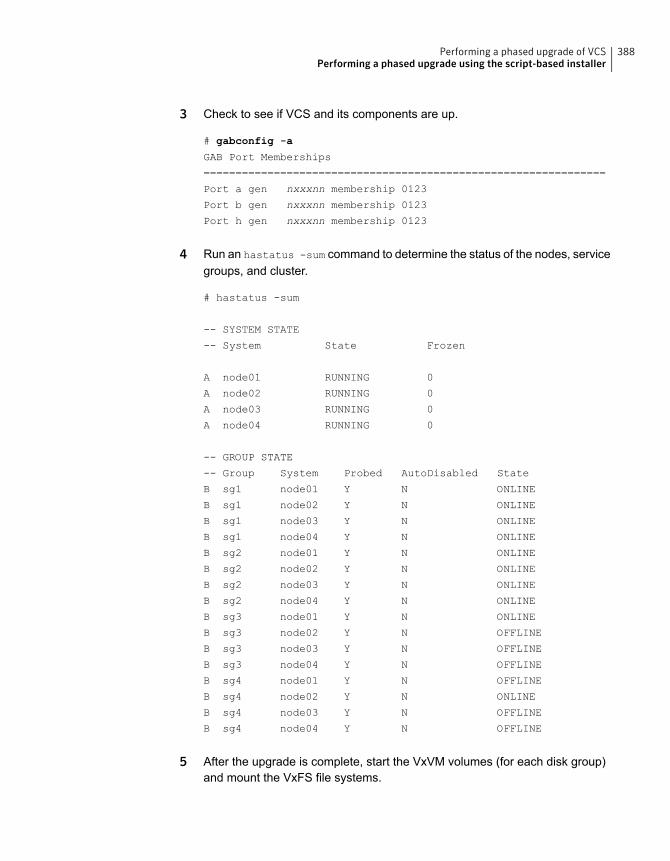
3 Check to see if VCS and its components are up.
# gabconfig -a
GAB Port Memberships
===============================================================
Port a gen nxxxnn membership 0123
Port b gen nxxxnn membership 0123
Port h gen nxxxnn membership 0123
4 Run an hastatus -sum command to determine the status of the nodes, servicegroups, and cluster.
# hastatus -sum
-- SYSTEM STATE
-- System State Frozen
A node01 RUNNING 0
A node02 RUNNING 0
A node03 RUNNING 0
A node04 RUNNING 0
-- GROUP STATE
-- Group System Probed AutoDisabled State
B sg1 node01 Y N ONLINE
B sg1 node02 Y N ONLINE
B sg1 node03 Y N ONLINE
B sg1 node04 Y N ONLINE
B sg2 node01 Y N ONLINE
B sg2 node02 Y N ONLINE
B sg2 node03 Y N ONLINE
B sg2 node04 Y N ONLINE
B sg3 node01 Y N ONLINE
B sg3 node02 Y N OFFLINE
B sg3 node03 Y N OFFLINE
B sg3 node04 Y N OFFLINE
B sg4 node01 Y N OFFLINE
B sg4 node02 Y N ONLINE
B sg4 node03 Y N OFFLINE
B sg4 node04 Y N OFFLINE
5 After the upgrade is complete, start the VxVM volumes (for each disk group)and mount the VxFS file systems.
388Performing a phased upgrade of VCSPerforming a phased upgrade using the script-based installer
In this example, you have performed a phased upgrade of VCS. The service groupswere down when you took them offline on node03 and node04, to the time VCSbrought them online on node01 or node02.
Note: If you want to upgrade application clusters that use CP server based fencingto 6.2, make sure that you first upgrade VCS or SFHA on the CP server systems.Then, upgrade all application clusters to version 6.2. However, note that the CPserver upgraded to 6.2 can support application clusters on 6.2 (HTTPS-basedcommunication) and application clusters prior to 6.2 (IPM-based communication).When you configure the CP server, the installer asks the VIPs for HTTPS-basedcommunication (if the clients are on release version 6.2) or VIPs for IPM-basedcommunication (if the clients are on a release version prior to 6.2).
For instructions to upgrade VCS or SFHA, see the VCS or SFHA Installation Guide.
389Performing a phased upgrade of VCSPerforming a phased upgrade using the script-based installer
Performing an automatedVCS upgrade usingresponse files
This chapter includes the following topics:
■ Upgrading VCS using response files
■ Response file variables to upgrade VCS
■ Sample response file for upgrading VCS
■ Performing rolling upgrade of VCS using response files
■ Response file variables to upgrade VCS using rolling upgrade
■ Sample response file for VCS using rolling upgrade
Upgrading VCS using response filesTypically, you can use the response file that the installer generates after you performVCS upgrade on one system to upgrade VCS on other systems.
You can also create a response file using the makeresponsefile option of theinstaller.
# ./installer -makeresponsefile
24Chapter
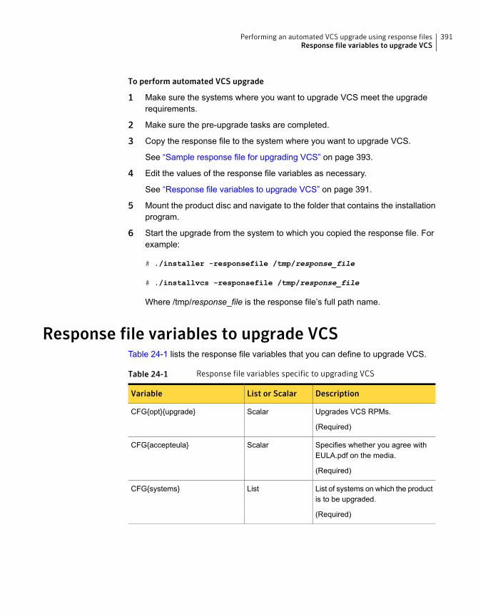
To perform automated VCS upgrade
1 Make sure the systems where you want to upgrade VCS meet the upgraderequirements.
2 Make sure the pre-upgrade tasks are completed.
3 Copy the response file to the system where you want to upgrade VCS.
See “Sample response file for upgrading VCS” on page 393.
4 Edit the values of the response file variables as necessary.
See “Response file variables to upgrade VCS” on page 391.
5 Mount the product disc and navigate to the folder that contains the installationprogram.
6 Start the upgrade from the system to which you copied the response file. Forexample:
# ./installer -responsefile /tmp/response_file
# ./installvcs -responsefile /tmp/response_file
Where /tmp/response_file is the response file’s full path name.
Response file variables to upgrade VCSTable 24-1 lists the response file variables that you can define to upgrade VCS.
Table 24-1 Response file variables specific to upgrading VCS
DescriptionList or ScalarVariable
Upgrades VCS RPMs.
(Required)
ScalarCFG{opt}{upgrade}
Specifies whether you agree withEULA.pdf on the media.
(Required)
ScalarCFG{accepteula}
List of systems on which the productis to be upgraded.
(Required)
ListCFG{systems}
391Performing an automated VCS upgrade using response filesResponse file variables to upgrade VCS

Table 24-1 Response file variables specific to upgrading VCS (continued)
DescriptionList or ScalarVariable
Defines the product to be upgraded.
The value is VCS62 for VCS.
(Optional)
ScalarCFG{prod}
Indicates whether or not to start LLTand GAB when you set up asingle-node cluster. The value canbe 0 (do not start) or 1 (start).
(Required)
ScalarCFG{vcs_allowcomms}
Defines the location of an ssh keyfilethat is used to communicate with allremote systems.
(Optional)
ScalarCFG{opt}{keyfile}
Defines a location, typically an NFSmount, from which all remotesystems can install product RPMs.The location must be accessiblefrom all target systems.
(Optional)
ScalarCFG{opt}{pkgpath}
Defines the location where aworking directory is created to storetemporary files and the RPMs thatare needed during the install. Thedefault location is /var/tmp.
(Optional)
ScalarCFG{opt}{tmppath}
Defines the user groups which getread access to the cluster.
(Optional)
ListCFG{secusrgrps}
392Performing an automated VCS upgrade using response filesResponse file variables to upgrade VCS
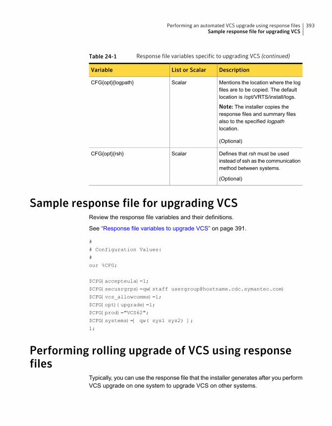
Table 24-1 Response file variables specific to upgrading VCS (continued)
DescriptionList or ScalarVariable
Mentions the location where the logfiles are to be copied. The defaultlocation is /opt/VRTS/install/logs.
Note: The installer copies theresponse files and summary filesalso to the specified logpathlocation.
(Optional)
ScalarCFG{opt}{logpath}
Defines that rsh must be usedinstead of ssh as the communicationmethod between systems.
(Optional)
ScalarCFG{opt}{rsh}
Sample response file for upgrading VCSReview the response file variables and their definitions.
See “Response file variables to upgrade VCS” on page 391.
#
# Configuration Values:
#
our %CFG;
$CFG{accepteula}=1;
$CFG{secusrgrps}=qw{staff [email protected]}
$CFG{vcs_allowcomms}=1;
$CFG{opt}{upgrade}=1;
$CFG{prod}="VCS62";
$CFG{systems}=[ qw( sys1 sys2) ];
1;
Performing rolling upgrade of VCS using responsefiles
Typically, you can use the response file that the installer generates after you performVCS upgrade on one system to upgrade VCS on other systems.
393Performing an automated VCS upgrade using response filesSample response file for upgrading VCS
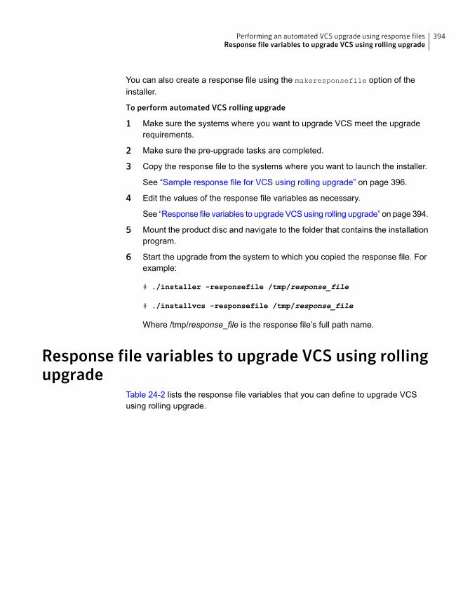
You can also create a response file using the makeresponsefile option of theinstaller.
To perform automated VCS rolling upgrade
1 Make sure the systems where you want to upgrade VCS meet the upgraderequirements.
2 Make sure the pre-upgrade tasks are completed.
3 Copy the response file to the systems where you want to launch the installer.
See “Sample response file for VCS using rolling upgrade” on page 396.
4 Edit the values of the response file variables as necessary.
See “Response file variables to upgrade VCS using rolling upgrade” on page 394.
5 Mount the product disc and navigate to the folder that contains the installationprogram.
6 Start the upgrade from the system to which you copied the response file. Forexample:
# ./installer -responsefile /tmp/response_file
# ./installvcs -responsefile /tmp/response_file
Where /tmp/response_file is the response file’s full path name.
Response file variables to upgrade VCS using rollingupgrade
Table 24-2 lists the response file variables that you can define to upgrade VCSusing rolling upgrade.
394Performing an automated VCS upgrade using response filesResponse file variables to upgrade VCS using rolling upgrade
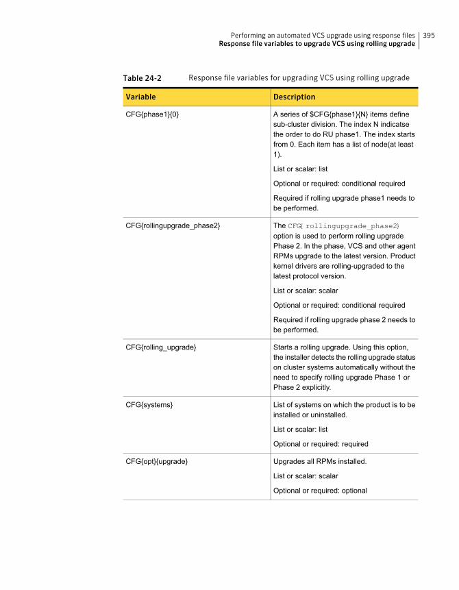
Table 24-2 Response file variables for upgrading VCS using rolling upgrade
DescriptionVariable
A series of $CFG{phase1}{N} items definesub-cluster division. The index N indicatsethe order to do RU phase1. The index startsfrom 0. Each item has a list of node(at least1).
List or scalar: list
Optional or required: conditional required
Required if rolling upgrade phase1 needs tobe performed.
CFG{phase1}{0}
The CFG{rollingupgrade_phase2}option is used to perform rolling upgradePhase 2. In the phase, VCS and other agentRPMs upgrade to the latest version. Productkernel drivers are rolling-upgraded to thelatest protocol version.
List or scalar: scalar
Optional or required: conditional required
Required if rolling upgrade phase 2 needs tobe performed.
CFG{rollingupgrade_phase2}
Starts a rolling upgrade. Using this option,the installer detects the rolling upgrade statuson cluster systems automatically without theneed to specify rolling upgrade Phase 1 orPhase 2 explicitly.
CFG{rolling_upgrade}
List of systems on which the product is to beinstalled or uninstalled.
List or scalar: list
Optional or required: required
CFG{systems}
Upgrades all RPMs installed.
List or scalar: scalar
Optional or required: optional
CFG{opt}{upgrade}
395Performing an automated VCS upgrade using response filesResponse file variables to upgrade VCS using rolling upgrade
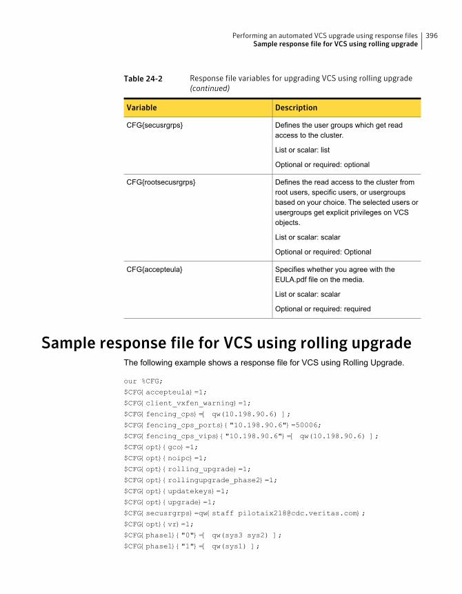
Table 24-2 Response file variables for upgrading VCS using rolling upgrade(continued)
DescriptionVariable
Defines the user groups which get readaccess to the cluster.
List or scalar: list
Optional or required: optional
CFG{secusrgrps}
Defines the read access to the cluster fromroot users, specific users, or usergroupsbased on your choice. The selected users orusergroups get explicit privileges on VCSobjects.
List or scalar: scalar
Optional or required: Optional
CFG{rootsecusrgrps}
Specifies whether you agree with theEULA.pdf file on the media.
List or scalar: scalar
Optional or required: required
CFG{accepteula}
Sample response file for VCS using rolling upgradeThe following example shows a response file for VCS using Rolling Upgrade.
our %CFG;
$CFG{accepteula}=1;
$CFG{client_vxfen_warning}=1;
$CFG{fencing_cps}=[ qw(10.198.90.6) ];
$CFG{fencing_cps_ports}{"10.198.90.6"}=50006;
$CFG{fencing_cps_vips}{"10.198.90.6"}=[ qw(10.198.90.6) ];
$CFG{opt}{gco}=1;
$CFG{opt}{noipc}=1;
$CFG{opt}{rolling_upgrade}=1;
$CFG{opt}{rollingupgrade_phase2}=1;
$CFG{opt}{updatekeys}=1;
$CFG{opt}{upgrade}=1;
$CFG{secusrgrps}=qw{staff [email protected]};
$CFG{opt}{vr}=1;
$CFG{phase1}{"0"}=[ qw(sys3 sys2) ];
$CFG{phase1}{"1"}=[ qw(sys1) ];
396Performing an automated VCS upgrade using response filesSample response file for VCS using rolling upgrade

$CFG{systems}=[ qw(sys1 sys2 sys3) ];
$CFG{vcs_allowcomms}=1;
1;
397Performing an automated VCS upgrade using response filesSample response file for VCS using rolling upgrade
Performing a rollingupgrade
This chapter includes the following topics:
■ About rolling upgrades
■ Supported rolling upgrade paths
■ Performing a rolling upgrade using the installer
■ Performing a rolling upgrade of VCS using the web-based installer
About rolling upgradesThe rolling upgrade minimizes downtime for highly available clusters to the amountof time that it takes to perform a service group failover. The rolling upgrade has twomain phases where the installer upgrades kernel RPMs in phase 1 and VCS agentrelated RPMs in phase 2.
Note: You need to perform a rolling upgrade on a completely configured cluster.
The following is an overview of the flow for a rolling upgrade:
The installer performs prechecks on the cluster.1.
25Chapter

The installer moves service groups to free nodes for the first phase of the upgradeas is needed.
Application downtime occurs during the first phase as the installer moves servicegroups to free nodes for the upgrade. The only downtime that is incurred is thenormal time required for the service group to fail over. The downtime is limited tothe applications that are failed over and not the entire cluster.
2.
The installer performs the second phase of the upgrade on all of the nodes in thecluster. The second phase of the upgrade includes downtime of the SymantecCluster Server (VCS) engine HAD, but does not include application downtime.
3.
Figure 25-1 illustrates an example of the installer performing a rolling upgrade forthree service groups on a two node cluster.
399Performing a rolling upgradeAbout rolling upgrades
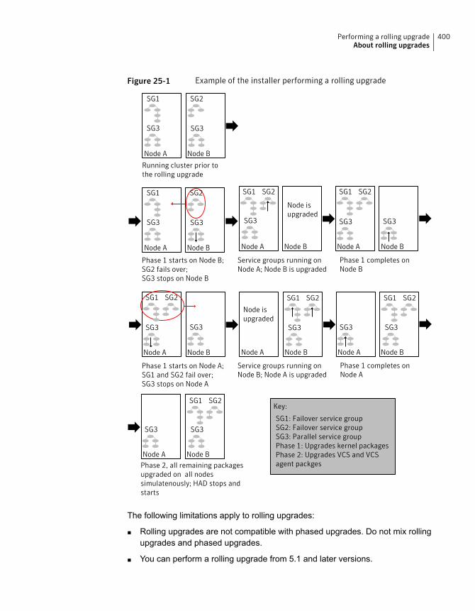
Figure 25-1 Example of the installer performing a rolling upgrade
Phase 1 starts on Node B;SG2 fails over;SG3 stops on Node B
Phase 2, all remaining packagesupgraded on all nodessimulatenously; HAD stops andstarts
SG1: Failover service groupSG2: Failover service groupSG3: Parallel service groupPhase 1: Upgrades kernel packagesPhase 2: Upgrades VCS and VCSagent packges
Node A Node B
SG3 SG3
SG1 SG2
Phase 1 completes onNode B
Phase 1 starts on Node A;SG1 and SG2 fail over;SG3 stops on Node A
Service groups running onNode A; Node B is upgraded
Phase 1 completes onNode A
Running cluster prior tothe rolling upgrade
Node A Node B
SG3 SG3
SG1 SG2
Node A Node B
SG1 SG2
SG3SG3
Node A Node B
SG3 SG3
SG1 SG2
Node A Node B
SG1 SG2
SG3SG3
Service groups running onNode B; Node A is upgraded
Node A Node B
SG3 SG3
SG1 SG2
Node isupgraded
Node A Node B
SG3
SG1 SG2
Node A Node B
SG1 SG2
SG3
Node isupgraded
Key:
The following limitations apply to rolling upgrades:
■ Rolling upgrades are not compatible with phased upgrades. Do not mix rollingupgrades and phased upgrades.
■ You can perform a rolling upgrade from 5.1 and later versions.
400Performing a rolling upgradeAbout rolling upgrades
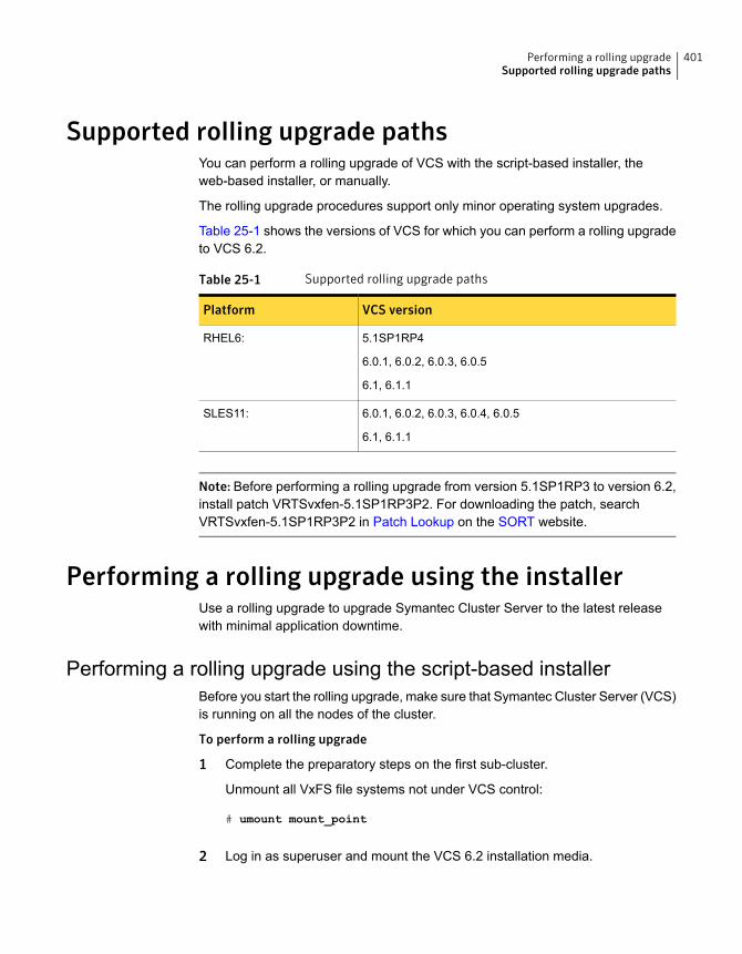
Supported rolling upgrade pathsYou can perform a rolling upgrade of VCS with the script-based installer, theweb-based installer, or manually.
The rolling upgrade procedures support only minor operating system upgrades.
Table 25-1 shows the versions of VCS for which you can perform a rolling upgradeto VCS 6.2.
Table 25-1 Supported rolling upgrade paths
VCS versionPlatform
5.1SP1RP4
6.0.1, 6.0.2, 6.0.3, 6.0.5
6.1, 6.1.1
RHEL6:
6.0.1, 6.0.2, 6.0.3, 6.0.4, 6.0.5
6.1, 6.1.1
SLES11:
Note: Before performing a rolling upgrade from version 5.1SP1RP3 to version 6.2,install patch VRTSvxfen-5.1SP1RP3P2. For downloading the patch, searchVRTSvxfen-5.1SP1RP3P2 in Patch Lookup on the SORT website.
Performing a rolling upgrade using the installerUse a rolling upgrade to upgrade Symantec Cluster Server to the latest releasewith minimal application downtime.
Performing a rolling upgrade using the script-based installerBefore you start the rolling upgrade, make sure that Symantec Cluster Server (VCS)is running on all the nodes of the cluster.
To perform a rolling upgrade
1 Complete the preparatory steps on the first sub-cluster.
Unmount all VxFS file systems not under VCS control:
# umount mount_point
2 Log in as superuser and mount the VCS 6.2 installation media.
401Performing a rolling upgradeSupported rolling upgrade paths
3 From root, start the installer.
# ./installer
4 From the menu, select Upgrade a Product and from the sub menu, selectRolling Upgrade.
5 The installer suggests system names for the upgrade. Press Enter to upgradethe suggested systems, or enter the name of any one system in the cluster onwhich you want to perform a rolling upgrade and then press Enter.
6 The installer checks system communications, release compatibility, versioninformation, and lists the cluster name, ID, and cluster nodes. Type y tocontinue.
7 The installer inventories the running service groups and determines the nodeor nodes to upgrade in phase 1 of the rolling upgrade. Type y to continue. Ifyou choose to specify the nodes, type n and enter the names of the nodes.
8 The installer performs further prechecks on the nodes in the cluster and maypresent warnings. You can type y to continue or quit the installer and addressthe precheck's warnings.
9 Review the end-user license agreement, and type y if you agree to its terms.
10 After the installer detects the online service groups, the installer prompts theuser to do one of the following:
■ Manually switch service groups
■ Use the CPI to automatically switch service groups
The downtime is the time that it normally takes for the service group's failover.
Note: It is recommended that you manually switch the service groups.Automatic switching of service groups does not resolve dependency issues.
11 The installer prompts you to stop the applicable processes. Type y to continue.
The installer evacuates all service groups to the node or nodes that are notupgraded at this time. The installer stops parallel service groups on the nodesthat are to be upgraded.
12 The installer stops relevant processes, uninstalls old kernel RPMs, and installsthe new RPMs. The installer asks if you want to update your licenses to thecurrent version. Select Yes or No. Symantec recommends that you updateyour licenses to fully use the new features in the current release.
402Performing a rolling upgradePerforming a rolling upgrade using the installer
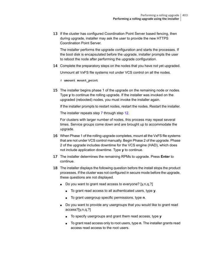
13 If the cluster has configured Coordination Point Server based fencing, thenduring upgrade, installer may ask the user to provide the new HTTPSCoordination Point Server.
The installer performs the upgrade configuration and starts the processes. Ifthe boot disk is encapsulated before the upgrade, installer prompts the userto reboot the node after performing the upgrade configuration.
14 Complete the preparatory steps on the nodes that you have not yet upgraded.
Unmount all VxFS file systems not under VCS control on all the nodes.
# umount mount_point
15 The installer begins phase 1 of the upgrade on the remaining node or nodes.Type y to continue the rolling upgrade. If the installer was invoked on theupgraded (rebooted) nodes, you must invoke the installer again.
If the installer prompts to restart nodes, restart the nodes. Restart the installer.
The installer repeats step 7 through step 12.
For clusters with larger number of nodes, this process may repeat severaltimes. Service groups come down and are brought up to accommodate theupgrade.
16 When Phase 1 of the rolling upgrade completes, mount all the VxFS file systemsthat are not under VCS control manually. Begin Phase 2 of the upgrade. Phase2 of the upgrade includes downtime for the VCS engine (HAD), which doesnot include application downtime. Type y to continue.
17 The installer determines the remaining RPMs to upgrade. Press Enter tocontinue.
18 The installer displays the following question before the install stops the productprocesses. If the cluster was not configured in secure mode before the upgrade,these questions are not displayed.
■ Do you want to grant read access to everyone? [y,n,q,?]
■ To grant read access to all authenticated users, type y.
■ To grant usergroup specific permissions, type n.
■ Do you want to provide any usergroups that you would like to grant readaccess?[y,n,q,?]
■ To specify usergroups and grant them read access, type y
■ To grant read access only to root users, type n. The installer grants readaccess read access to the root users.
403Performing a rolling upgradePerforming a rolling upgrade using the installer
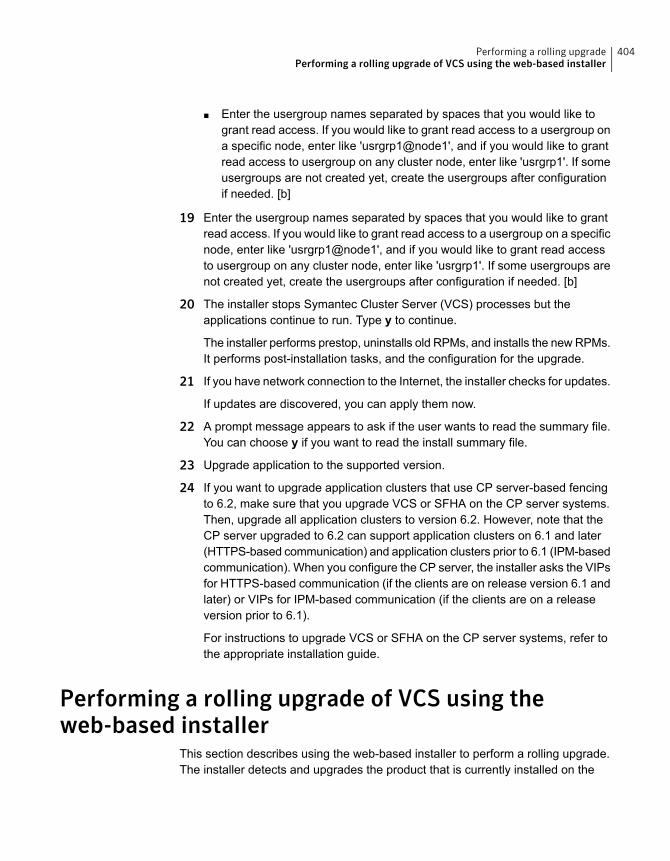
■ Enter the usergroup names separated by spaces that you would like togrant read access. If you would like to grant read access to a usergroup ona specific node, enter like 'usrgrp1@node1', and if you would like to grantread access to usergroup on any cluster node, enter like 'usrgrp1'. If someusergroups are not created yet, create the usergroups after configurationif needed. [b]
19 Enter the usergroup names separated by spaces that you would like to grantread access. If you would like to grant read access to a usergroup on a specificnode, enter like 'usrgrp1@node1', and if you would like to grant read accessto usergroup on any cluster node, enter like 'usrgrp1'. If some usergroups arenot created yet, create the usergroups after configuration if needed. [b]
20 The installer stops Symantec Cluster Server (VCS) processes but theapplications continue to run. Type y to continue.
The installer performs prestop, uninstalls old RPMs, and installs the new RPMs.It performs post-installation tasks, and the configuration for the upgrade.
21 If you have network connection to the Internet, the installer checks for updates.
If updates are discovered, you can apply them now.
22 A prompt message appears to ask if the user wants to read the summary file.You can choose y if you want to read the install summary file.
23 Upgrade application to the supported version.
24 If you want to upgrade application clusters that use CP server-based fencingto 6.2, make sure that you upgrade VCS or SFHA on the CP server systems.Then, upgrade all application clusters to version 6.2. However, note that theCP server upgraded to 6.2 can support application clusters on 6.1 and later(HTTPS-based communication) and application clusters prior to 6.1 (IPM-basedcommunication). When you configure the CP server, the installer asks the VIPsfor HTTPS-based communication (if the clients are on release version 6.1 andlater) or VIPs for IPM-based communication (if the clients are on a releaseversion prior to 6.1).
For instructions to upgrade VCS or SFHA on the CP server systems, refer tothe appropriate installation guide.
Performing a rolling upgrade of VCS using theweb-based installer
This section describes using the web-based installer to perform a rolling upgrade.The installer detects and upgrades the product that is currently installed on the
404Performing a rolling upgradePerforming a rolling upgrade of VCS using the web-based installer
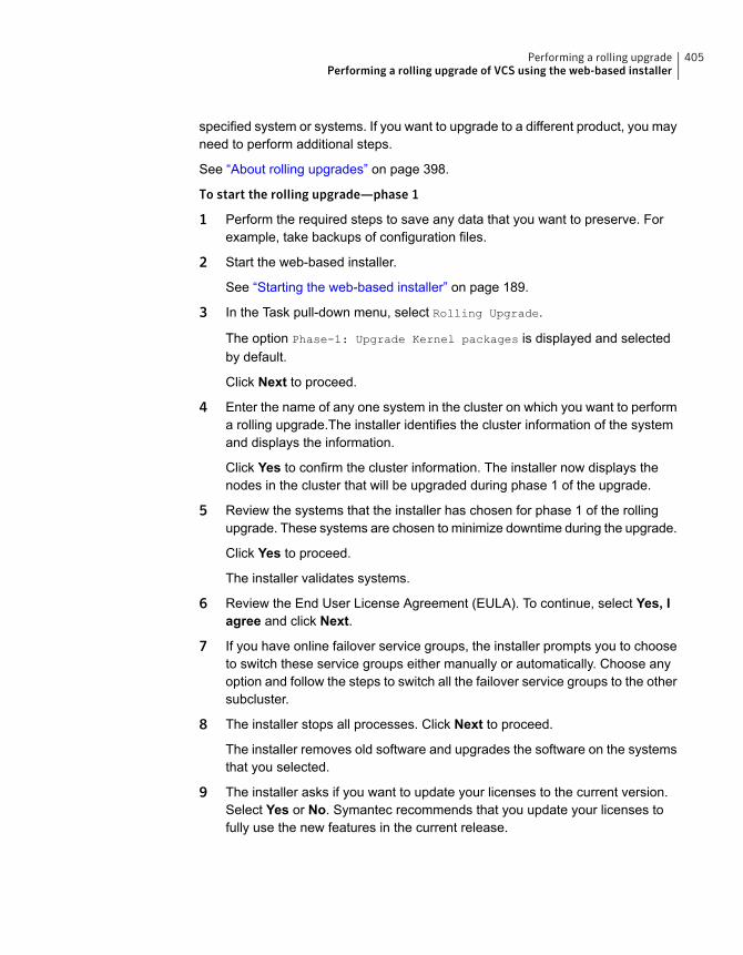
specified system or systems. If you want to upgrade to a different product, you mayneed to perform additional steps.
See “About rolling upgrades” on page 398.
To start the rolling upgrade—phase 1
1 Perform the required steps to save any data that you want to preserve. Forexample, take backups of configuration files.
2 Start the web-based installer.
See “Starting the web-based installer” on page 189.
3 In the Task pull-down menu, select Rolling Upgrade.
The option Phase-1: Upgrade Kernel packages is displayed and selectedby default.
Click Next to proceed.
4 Enter the name of any one system in the cluster on which you want to performa rolling upgrade.The installer identifies the cluster information of the systemand displays the information.
Click Yes to confirm the cluster information. The installer now displays thenodes in the cluster that will be upgraded during phase 1 of the upgrade.
5 Review the systems that the installer has chosen for phase 1 of the rollingupgrade. These systems are chosen to minimize downtime during the upgrade.
Click Yes to proceed.
The installer validates systems.
6 Review the End User License Agreement (EULA). To continue, select Yes, Iagree and click Next.
7 If you have online failover service groups, the installer prompts you to chooseto switch these service groups either manually or automatically. Choose anyoption and follow the steps to switch all the failover service groups to the othersubcluster.
8 The installer stops all processes. Click Next to proceed.
The installer removes old software and upgrades the software on the systemsthat you selected.
9 The installer asks if you want to update your licenses to the current version.Select Yes or No. Symantec recommends that you update your licenses tofully use the new features in the current release.
405Performing a rolling upgradePerforming a rolling upgrade of VCS using the web-based installer
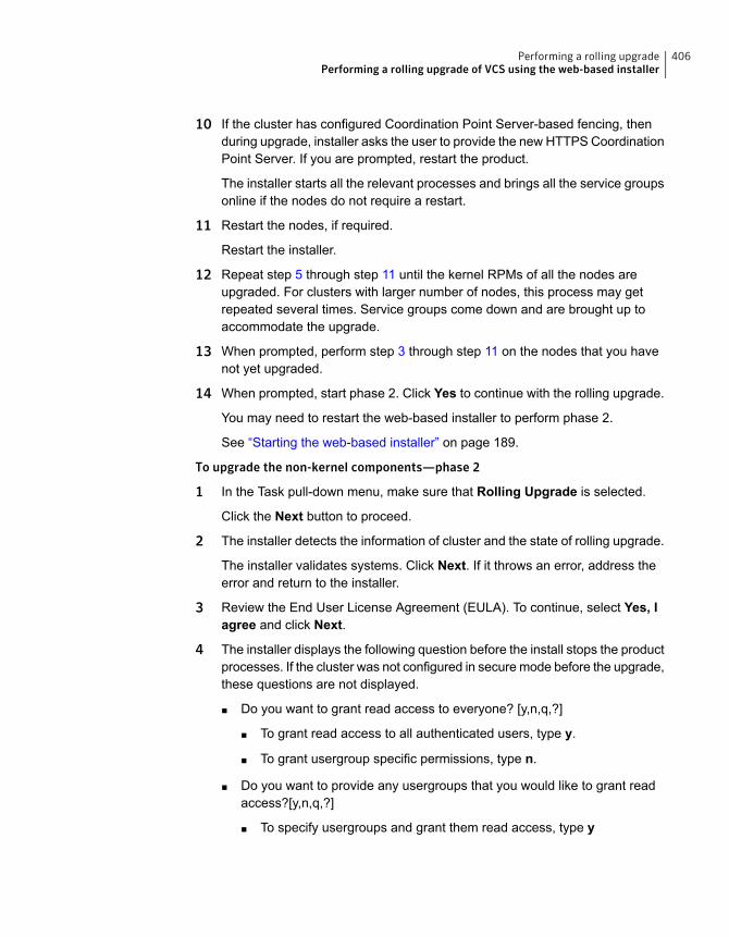
10 If the cluster has configured Coordination Point Server-based fencing, thenduring upgrade, installer asks the user to provide the new HTTPS CoordinationPoint Server. If you are prompted, restart the product.
The installer starts all the relevant processes and brings all the service groupsonline if the nodes do not require a restart.
11 Restart the nodes, if required.
Restart the installer.
12 Repeat step 5 through step 11 until the kernel RPMs of all the nodes areupgraded. For clusters with larger number of nodes, this process may getrepeated several times. Service groups come down and are brought up toaccommodate the upgrade.
13 When prompted, perform step 3 through step 11 on the nodes that you havenot yet upgraded.
14 When prompted, start phase 2. Click Yes to continue with the rolling upgrade.
You may need to restart the web-based installer to perform phase 2.
See “Starting the web-based installer” on page 189.
To upgrade the non-kernel components—phase 2
1 In the Task pull-down menu, make sure that Rolling Upgrade is selected.
Click the Next button to proceed.
2 The installer detects the information of cluster and the state of rolling upgrade.
The installer validates systems. Click Next. If it throws an error, address theerror and return to the installer.
3 Review the End User License Agreement (EULA). To continue, select Yes, Iagree and click Next.
4 The installer displays the following question before the install stops the productprocesses. If the cluster was not configured in secure mode before the upgrade,these questions are not displayed.
■ Do you want to grant read access to everyone? [y,n,q,?]
■ To grant read access to all authenticated users, type y.
■ To grant usergroup specific permissions, type n.
■ Do you want to provide any usergroups that you would like to grant readaccess?[y,n,q,?]
■ To specify usergroups and grant them read access, type y
406Performing a rolling upgradePerforming a rolling upgrade of VCS using the web-based installer
■ To grant read access only to root users, type n. The installer grants readaccess read access to the root users.
■ Enter the usergroup names separated by spaces that you would like togrant read access. If you would like to grant read access to a usergroup ona specific node, enter like 'usrgrp1@node1', and if you would like to grantread access to usergroup on any cluster node, enter like 'usrgrp1'. If someusergroups are not created yet, create the usergroups after configurationif needed. [b]
5 The installer stops the HAD and CmdServer processes in phase 2 of the rollingupgrade process but the applications continue to run. Click Next to proceed.
6 The installer removes old software and upgrades the software on the systemsthat you selected. Review the output and click theNext button when prompted.Register the software and click Next to proceed. The installer starts all therelevant processes and brings all the service groups online.
7 If you have network connection to the Internet, the installer checks for updates.
If updates are discovered, you can apply them now.
8 A prompt message appears to ask if the user wants to read the summary file.You can choose y if you want to read the install summary file.
The upgrade is complete.
407Performing a rolling upgradePerforming a rolling upgrade of VCS using the web-based installer
Post-installation tasks
■ Chapter 26. Performing post-installation tasks
■ Chapter 27. Installing or upgrading VCS components
■ Chapter 28. Verifying the VCS installation
9Section
Performingpost-installation tasks
This chapter includes the following topics:
■ About enabling LDAP authentication for clusters that run in secure mode
■ Accessing the VCS documentation
■ Removing permissions for communication
About enabling LDAP authentication for clusters thatrun in secure mode
Symantec Product Authentication Service (AT) supports LDAP (Lightweight DirectoryAccess Protocol) user authentication through a plug-in for the authentication broker.AT supports all common LDAP distributions such as OpenLDAP and WindowsActive Directory.
For a cluster that runs in secure mode, you must enable the LDAP authenticationplug-in if the VCS users belong to an LDAP domain.
If you have not already added VCS users during installation, you can add the userslater.
See the Symantec Cluster Server Administrator's Guide for instructions to add VCSusers.
Figure 26-1 depicts the VCS cluster communication with the LDAP servers whenclusters run in secure mode.
26Chapter
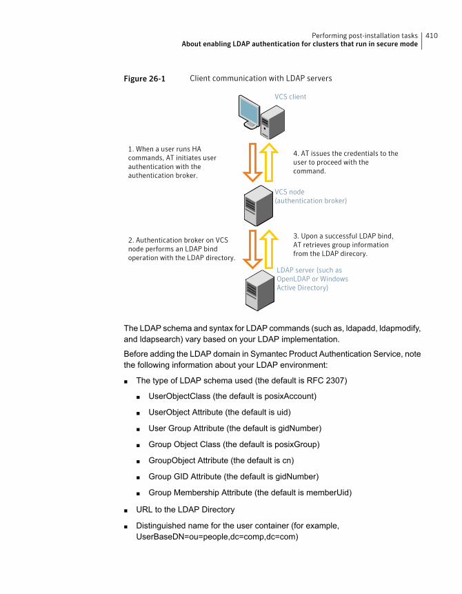
Figure 26-1 Client communication with LDAP servers
VCS node(authentication broker)
VCS client
1. When a user runs HAcommands, AT initiates userauthentication with theauthentication broker.
4. AT issues the credentials to theuser to proceed with thecommand.
2. Authentication broker on VCSnode performs an LDAP bindoperation with the LDAP directory.
3. Upon a successful LDAP bind,AT retrieves group informationfrom the LDAP direcory.
LDAP server (such asOpenLDAP or WindowsActive Directory)
The LDAP schema and syntax for LDAP commands (such as, ldapadd, ldapmodify,and ldapsearch) vary based on your LDAP implementation.
Before adding the LDAP domain in Symantec Product Authentication Service, notethe following information about your LDAP environment:
■ The type of LDAP schema used (the default is RFC 2307)
■ UserObjectClass (the default is posixAccount)
■ UserObject Attribute (the default is uid)
■ User Group Attribute (the default is gidNumber)
■ Group Object Class (the default is posixGroup)
■ GroupObject Attribute (the default is cn)
■ Group GID Attribute (the default is gidNumber)
■ Group Membership Attribute (the default is memberUid)
■ URL to the LDAP Directory
■ Distinguished name for the user container (for example,UserBaseDN=ou=people,dc=comp,dc=com)
410Performing post-installation tasksAbout enabling LDAP authentication for clusters that run in secure mode
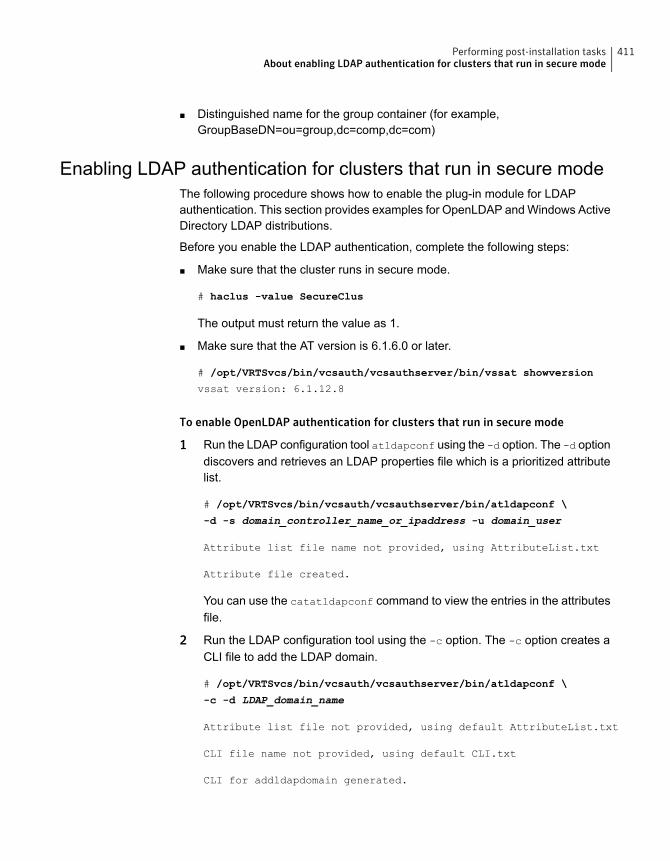
■ Distinguished name for the group container (for example,GroupBaseDN=ou=group,dc=comp,dc=com)
Enabling LDAP authentication for clusters that run in secure modeThe following procedure shows how to enable the plug-in module for LDAPauthentication. This section provides examples for OpenLDAP and Windows ActiveDirectory LDAP distributions.
Before you enable the LDAP authentication, complete the following steps:
■ Make sure that the cluster runs in secure mode.
# haclus -value SecureClus
The output must return the value as 1.
■ Make sure that the AT version is 6.1.6.0 or later.
# /opt/VRTSvcs/bin/vcsauth/vcsauthserver/bin/vssat showversion
vssat version: 6.1.12.8
To enable OpenLDAP authentication for clusters that run in secure mode
1 Run the LDAP configuration tool atldapconf using the -d option. The -d optiondiscovers and retrieves an LDAP properties file which is a prioritized attributelist.
# /opt/VRTSvcs/bin/vcsauth/vcsauthserver/bin/atldapconf \
-d -s domain_controller_name_or_ipaddress -u domain_user
Attribute list file name not provided, using AttributeList.txt
Attribute file created.
You can use the catatldapconf command to view the entries in the attributesfile.
2 Run the LDAP configuration tool using the -c option. The -c option creates aCLI file to add the LDAP domain.
# /opt/VRTSvcs/bin/vcsauth/vcsauthserver/bin/atldapconf \
-c -d LDAP_domain_name
Attribute list file not provided, using default AttributeList.txt
CLI file name not provided, using default CLI.txt
CLI for addldapdomain generated.
411Performing post-installation tasksAbout enabling LDAP authentication for clusters that run in secure mode

3 Run the LDAP configuration tool atldapconf using the -x option. The -x optionreads the CLI file and executes the commands to add a domain to the AT.
# /opt/VRTSvcs/bin/vcsauth/vcsauthserver/bin/atldapconf -x
Using default broker port 14149
CLI file not provided, using default CLI.txt
Looking for AT installation...
AT found installed at ./vssat
Successfully added LDAP domain.
412Performing post-installation tasksAbout enabling LDAP authentication for clusters that run in secure mode
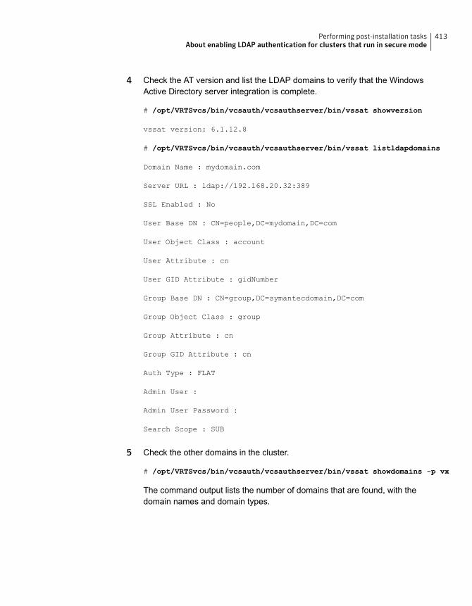
4 Check the AT version and list the LDAP domains to verify that the WindowsActive Directory server integration is complete.
# /opt/VRTSvcs/bin/vcsauth/vcsauthserver/bin/vssat showversion
vssat version: 6.1.12.8
# /opt/VRTSvcs/bin/vcsauth/vcsauthserver/bin/vssat listldapdomains
Domain Name : mydomain.com
Server URL : ldap://192.168.20.32:389
SSL Enabled : No
User Base DN : CN=people,DC=mydomain,DC=com
User Object Class : account
User Attribute : cn
User GID Attribute : gidNumber
Group Base DN : CN=group,DC=symantecdomain,DC=com
Group Object Class : group
Group Attribute : cn
Group GID Attribute : cn
Auth Type : FLAT
Admin User :
Admin User Password :
Search Scope : SUB
5 Check the other domains in the cluster.
# /opt/VRTSvcs/bin/vcsauth/vcsauthserver/bin/vssat showdomains -p vx
The command output lists the number of domains that are found, with thedomain names and domain types.
413Performing post-installation tasksAbout enabling LDAP authentication for clusters that run in secure mode
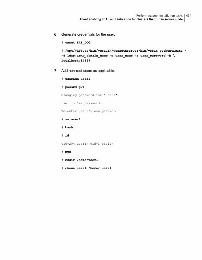
6 Generate credentials for the user.
# unset EAT_LOG
# /opt/VRTSvcs/bin/vcsauth/vcsauthserver/bin/vssat authenticate \
-d ldap:LDAP_domain_name -p user_name -s user_password -b \
localhost:14149
7 Add non-root users as applicable.
# useradd user1
# passwd pw1
Changing password for "user1"
user1's New password:
Re-enter user1's new password:
# su user1
# bash
# id
uid=204(user1) gid=1(staff)
# pwd
# mkdir /home/user1
# chown user1 /home/ user1
414Performing post-installation tasksAbout enabling LDAP authentication for clusters that run in secure mode
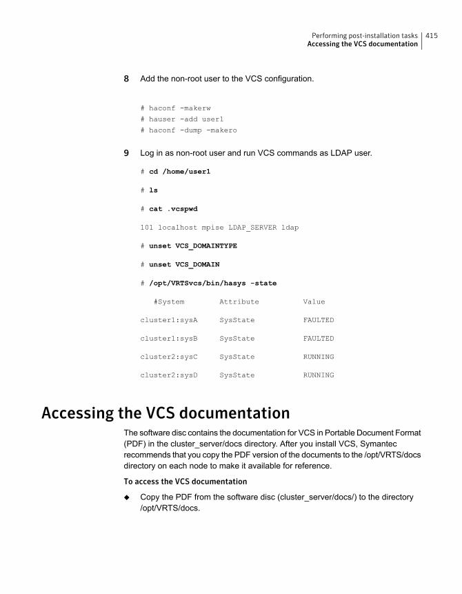
8 Add the non-root user to the VCS configuration.
# haconf -makerw
# hauser -add user1
# haconf -dump -makero
9 Log in as non-root user and run VCS commands as LDAP user.
# cd /home/user1
# ls
# cat .vcspwd
101 localhost mpise LDAP_SERVER ldap
# unset VCS_DOMAINTYPE
# unset VCS_DOMAIN
# /opt/VRTSvcs/bin/hasys -state
#System Attribute Value
cluster1:sysA SysState FAULTED
cluster1:sysB SysState FAULTED
cluster2:sysC SysState RUNNING
cluster2:sysD SysState RUNNING
Accessing the VCS documentationThe software disc contains the documentation for VCS in Portable Document Format(PDF) in the cluster_server/docs directory. After you install VCS, Symantecrecommends that you copy the PDF version of the documents to the /opt/VRTS/docsdirectory on each node to make it available for reference.
To access the VCS documentation
◆ Copy the PDF from the software disc (cluster_server/docs/) to the directory/opt/VRTS/docs.
415Performing post-installation tasksAccessing the VCS documentation
Removing permissions for communicationMake sure you completed the installation of VCS and the verification of disk supportfor I/O fencing. If you used rsh, remove the temporary rsh access permissions thatyou set for the nodes and restore the connections to the public network.
If the nodes use ssh for secure communications, and you temporarily removed theconnections to the public network, restore the connections.
416Performing post-installation tasksRemoving permissions for communication
Installing or upgrading VCScomponents
This chapter includes the following topics:
■ Installing the Java Console
■ Upgrading the Java Console
■ Installing VCS Simulator
■ Upgrading VCS Simulator
■ Upgrading the VCS agents
Installing the Java ConsoleYou can administer VCS using the VCS Java-based graphical user interface, JavaConsole. After VCS has been installed, install the Java Console on a Windowssystem or Linux system. Review the software requirements for Java Console.
The system from which you run the Java Console can be a system in the clusteror a remote workstation. A remote workstation enables each system in the clusterto be administered remotely.
Review the information about using the Java Console. For more information, referto the Symantec Cluster Server Administrator's Guide.
Software requirements for the Java ConsoleCluster Manager (Java Console) is supported on:
■ RHEL 4 Update 3 or later, RHEL 5 or later, SLES 9 SP3
■ Windows XP and Windows 2003
27Chapter
Note:Make sure that you are using an operating system version that supports JRE1.6.
Hardware requirements for the Java ConsoleThe minimum hardware requirements for the Java Console are as follows:
■ Pentium II 300 megahertz
■ 256 megabytes of RAM
■ 800x600 display resolution
■ 8-bit color depth of the monitor
■ A graphics card that is capable of 2D images
Note: Symantec recommends using Pentium III 400MHz or higher, 256MB RAMor higher, and 800x600 display resolution or higher.
The version of the Java™ 2 Runtime Environment (JRE) requires 32 megabytesof RAM.
This version is supported on the Intel Pentium platforms that run the Linux kernelv 2.2.12 and glibc v2.1.2-11 (or later).
Symantec recommends using the following hardware:
■ 48 megabytes of RAM
■ 16-bit color mode
■ The KDE and the KWM window managers that are used with displays set tolocal hosts
Installing the Java Console on LinuxReview the procedure to install the Java console. Before you begin with theprocedure, ensure that you have the gunzip utility installed on your system.
To install Java console on Linux
1 Download the Java GUI utility from http://go.symantec.com/vcsm_downloadto a temporary directory.
2 Install the RPM using rpm -i command.
# rpm -i VCS_Cluster_Manager_Java_Console_5.5_for_Linux.rpm
418Installing or upgrading VCS componentsInstalling the Java Console
Installing the Java Console on a Windows systemReview the procedure to install the Java console on a Windows system.
To install the Java Console on a Windows system
1 Download the Java GUI utility from http://go.symantec.com/vcsm_downloadto a temporary directory.
2 Extract the zipped file to a temporary folder.
3 From this extracted folder, double-click setup.exe.
4 The Symantec Cluster Manager Install Wizard guides you through theinstallation process.
Upgrading the Java ConsoleUse one of the following applicable procedures to upgrade Java Console.
To upgrade Java console on Linux
1 Log in as superuser on the node where you intend to install the RPM.
2 Remove the GUI from the previous installation.
# rpm -e VRTScscm
3 Install the VCS Java console.
See “Installing the Java Console on Linux” on page 418.
To upgrade the Java Console on a Windows client
1 Stop Cluster Manager (Java Console) if it is running.
2 Remove Cluster Manager from the system.
■ From the Control Panel, double-click Add/Remove Programs
■ Select Veritas Cluster Manager.
■ Click Add/Remove.
■ Follow the uninstall wizard instructions.
3 Install the new Cluster Manager.
See “Installing the Java Console on a Windows system” on page 419.
419Installing or upgrading VCS componentsUpgrading the Java Console
Installing VCS SimulatorYou can administer VCS Simulator from the Java Console or from the commandline. For more information, see the Symantec Cluster Server Administrator's Guide.
Review the software requirements for VCS Simulator.
Software requirements for VCS SimulatorVCS Simulator is supported on:
■ Windows XP SP3, Windows 2008, Windows Vista, and Windows 7
Note:Make sure that you are using an operating system version that supports JRE1.6 or later.
Installing VCS Simulator on Windows systemsThis section describes the procedure to install VCS Simulator on Windows systems.
To install VCS Simulator on Windows systems
1 Download VCS Simulator from the following location to a temporary directory.
http://www.symantec.com/business/cluster-server and click Utilities.
2 Extract the compressed files to another directory.
3 Navigate to the path of the Simulator installer file:
\your_platform_architecture\cluster_server\windows\VCSWindowsInstallers\Simulator
4 Double-click the installer file.
5 Read the information in the Welcome screen and click Next.
6 In the Destination Folders dialog box, click Next to accepted the suggestedinstallation path or click Change to choose a different location.
7 In the Ready to Install the Program dialog box, click Back to make changesto your selections or click Install to proceed with the installation.
8 In the Installshield Wizard Completed dialog box, click Finish.
Reviewing the installationVCS Simulator installs Cluster Manager (Java Console) and Simulator binaries onthe system. The Simulator installation creates the following directories:
420Installing or upgrading VCS componentsInstalling VCS Simulator
ContentDirectory
Information about attributes associated with VCS objectsattrpool
VCS Simulator binariesbin
Files for the default cluster configurationdefault_clus
A sample cluster configuration, which serves as a template for eachnew cluster configuration
sample_clus
Various templates that are used by the Java Consoletemplates
The types.cf files for all supported platformstypes
Contains another directory called types. This directory containsassorted resource type definitions that are useful for the Simulator.The type definition files are present in platform-specific subdirectories.
conf
Additionally, VCS Simulator installs directories for various cluster configurations.
VCS Simulator creates a directory for every new simulated cluster and copies thecontents of the sample_clus directory. Simulator also creates a log directory withineach cluster directory for logs that are associated with the cluster.
Upgrading VCS SimulatorUse the following procedure to upgrade VCS Simulator.
To upgrade VCS Simulator on a Windows client
1 Stop all instances of VCS Simulator.
2 Stop VCS Simulator, if it is running.
3 Remove VCS Simulator from the system.
■ From the Control Panel, double-click Add/Remove Programs
■ Select VCS Simulator.
■ Click Add/Remove.
■ Follow the uninstall wizard instructions.
4 Install the new Simulator.
See “Installing VCS Simulator on Windows systems” on page 420.
421Installing or upgrading VCS componentsUpgrading VCS Simulator
Upgrading the VCS agentsThe installvcs program does not upgrade the VCS agents for DB2, Oracle, andSybase. If previous versions of these agents are installed on your cluster, you mustuninstall the previous version of the agents and manually install the new agentversion.
The product installer includes the VCS agents for DB2, Oracle, and Sybase as abundled RPM.
To upgrade the VCS agents
1 Before you install, log in as the superuser. Mount the disc, and copy the filesin a temporary folder for installation.
2 Use following command to install the VCS agents RPM:
# rpm -ivh VRTSvcsea-6.100.000-GA_dist.arch.rpm
where dist is the operating system and takes the values RHEL6, RHEL7 orSLES 11.
arch is the architecture. It takes the values i586 or i686 for RHEL6, RHEL7and SLES11.
See the agent Installation and Configuration Guide for more information on theagent that you want to upgrade.
See Symantec Cluster Server Release Notes for supported versions of the agents.
422Installing or upgrading VCS componentsUpgrading the VCS agents
Verifying the VCSinstallation
This chapter includes the following topics:
■ About verifying the VCS installation
■ About the cluster UUID
■ Verifying the LLT, GAB, and VCS configuration files
■ Verifying LLT, GAB, and cluster operation
■ Upgrading the disk group version
■ Performing a postcheck on a node
About verifying the VCS installationAfter you install and configure VCS, you can inspect the contents of the key VCSconfiguration files that you have installed and modified during the process. Thesefiles reflect the configuration that is based on the information you supplied. You canalso run VCS commands to verify the status of LLT, GAB, and the cluster.
About the cluster UUIDYou can verify the existence of the cluster UUID.
To verify that the cluster UUID exists
◆ From the prompt, run a cat command.
cat /etc/vx/.uuids/clusuuid
28Chapter
To display UUID of all the nodes in the cluster
◆ From the prompt, run the command from any node.
/opt/VRTSvcs/bin/uuidconfig.pl -rsh -clus -display -use_llthost
Verifying the LLT, GAB, and VCS configuration filesMake sure that the LLT, GAB, and VCS configuration files contain the informationyou provided during VCS installation and configuration.
To verify the LLT, GAB, and VCS configuration files
1 Navigate to the location of the configuration files:
■ LLT/etc/llthosts/etc/llttab
■ GAB/etc/gabtab
■ VCS/etc/VRTSvcs/conf/config/main.cf
2 Verify the content of the configuration files.
See “About the LLT and GAB configuration files” on page 501.
See “About the VCS configuration files” on page 505.
Verifying LLT, GAB, and cluster operationVerify the operation of LLT, GAB, and the cluster using the VCS commands.
To verify LLT, GAB, and cluster operation
1 Log in to any node in the cluster as superuser.
2 Make sure that the PATH environment variable is set to run the VCS commands.
See “Setting the PATH variable” on page 74.
3 Verify LLT operation.
See “Verifying LLT” on page 425.
4 Verify GAB operation.
See “Verifying GAB” on page 427.
424Verifying the VCS installationVerifying the LLT, GAB, and VCS configuration files
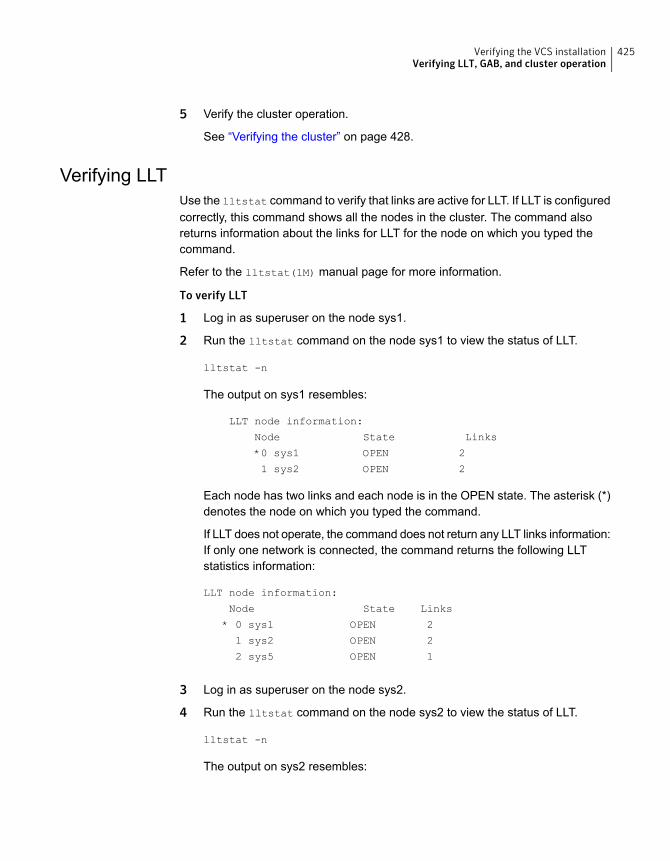
5 Verify the cluster operation.
See “Verifying the cluster” on page 428.
Verifying LLTUse the lltstat command to verify that links are active for LLT. If LLT is configuredcorrectly, this command shows all the nodes in the cluster. The command alsoreturns information about the links for LLT for the node on which you typed thecommand.
Refer to the lltstat(1M) manual page for more information.
To verify LLT
1 Log in as superuser on the node sys1.
2 Run the lltstat command on the node sys1 to view the status of LLT.
lltstat -n
The output on sys1 resembles:
LLT node information:
Node State Links
*0 sys1 OPEN 2
1 sys2 OPEN 2
Each node has two links and each node is in the OPEN state. The asterisk (*)denotes the node on which you typed the command.
If LLT does not operate, the command does not return any LLT links information:If only one network is connected, the command returns the following LLTstatistics information:
LLT node information:
Node State Links
* 0 sys1 OPEN 2
1 sys2 OPEN 2
2 sys5 OPEN 1
3 Log in as superuser on the node sys2.
4 Run the lltstat command on the node sys2 to view the status of LLT.
lltstat -n
The output on sys2 resembles:
425Verifying the VCS installationVerifying LLT, GAB, and cluster operation
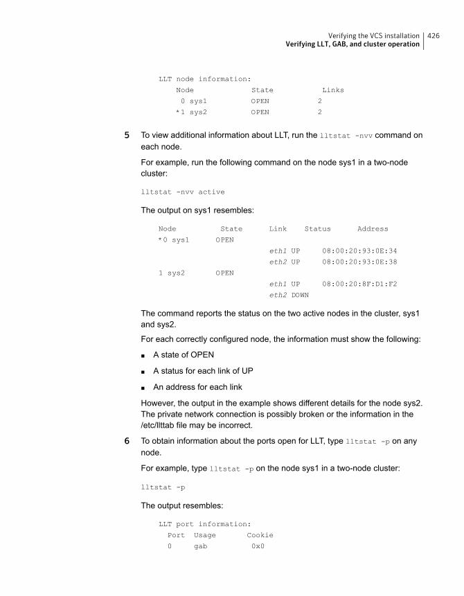
LLT node information:
Node State Links
0 sys1 OPEN 2
*1 sys2 OPEN 2
5 To view additional information about LLT, run the lltstat -nvv command oneach node.
For example, run the following command on the node sys1 in a two-nodecluster:
lltstat -nvv active
The output on sys1 resembles:
Node State Link Status Address
*0 sys1 OPEN
eth1 UP 08:00:20:93:0E:34
eth2 UP 08:00:20:93:0E:38
1 sys2 OPEN
eth1 UP 08:00:20:8F:D1:F2
eth2 DOWN
The command reports the status on the two active nodes in the cluster, sys1and sys2.
For each correctly configured node, the information must show the following:
■ A state of OPEN
■ A status for each link of UP
■ An address for each link
However, the output in the example shows different details for the node sys2.The private network connection is possibly broken or the information in the/etc/llttab file may be incorrect.
6 To obtain information about the ports open for LLT, type lltstat -p on anynode.
For example, type lltstat -p on the node sys1 in a two-node cluster:
lltstat -p
The output resembles:
LLT port information:
Port Usage Cookie
0 gab 0x0
426Verifying the VCS installationVerifying LLT, GAB, and cluster operation
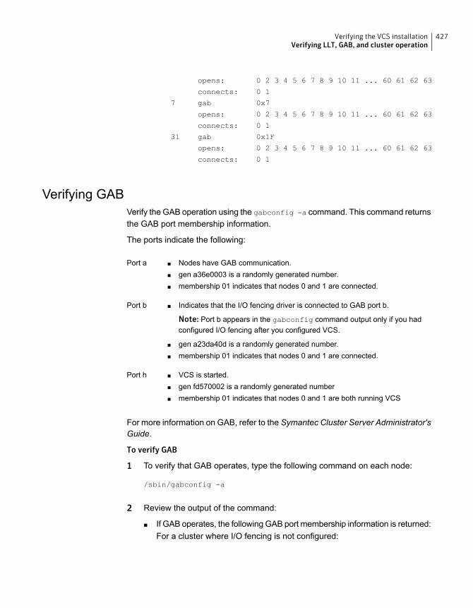
opens: 0 2 3 4 5 6 7 8 9 10 11 ... 60 61 62 63
connects: 0 1
7 gab 0x7
opens: 0 2 3 4 5 6 7 8 9 10 11 ... 60 61 62 63
connects: 0 1
31 gab 0x1F
opens: 0 2 3 4 5 6 7 8 9 10 11 ... 60 61 62 63
connects: 0 1
Verifying GABVerify the GAB operation using the gabconfig -a command. This command returnsthe GAB port membership information.
The ports indicate the following:
■ Nodes have GAB communication.■ gen a36e0003 is a randomly generated number.■ membership 01 indicates that nodes 0 and 1 are connected.
Port a
■ Indicates that the I/O fencing driver is connected to GAB port b.
Note: Port b appears in the gabconfig command output only if you hadconfigured I/O fencing after you configured VCS.
■ gen a23da40d is a randomly generated number.■ membership 01 indicates that nodes 0 and 1 are connected.
Port b
■ VCS is started.■ gen fd570002 is a randomly generated number■ membership 01 indicates that nodes 0 and 1 are both running VCS
Port h
For more information on GAB, refer to the Symantec Cluster Server Administrator'sGuide.
To verify GAB
1 To verify that GAB operates, type the following command on each node:
/sbin/gabconfig -a
2 Review the output of the command:
■ If GAB operates, the following GAB port membership information is returned:For a cluster where I/O fencing is not configured:
427Verifying the VCS installationVerifying LLT, GAB, and cluster operation
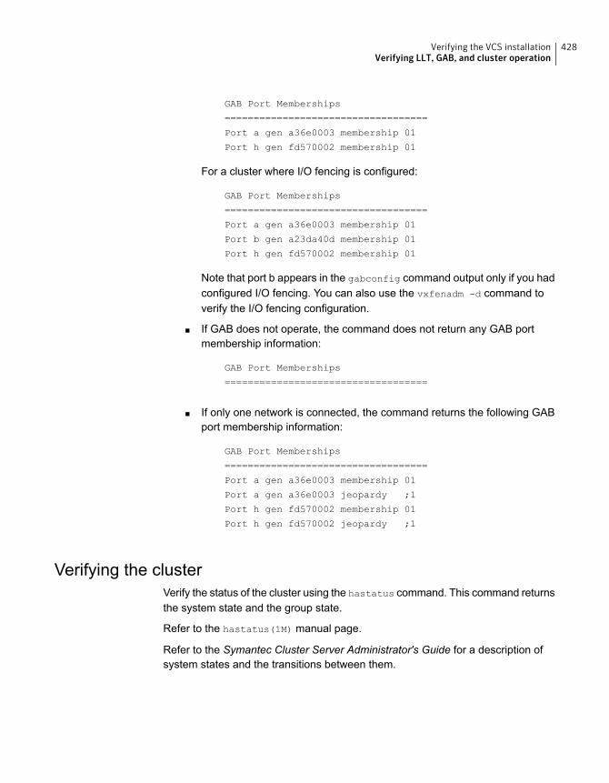
GAB Port Memberships
===================================
Port a gen a36e0003 membership 01
Port h gen fd570002 membership 01
For a cluster where I/O fencing is configured:
GAB Port Memberships
===================================
Port a gen a36e0003 membership 01
Port b gen a23da40d membership 01
Port h gen fd570002 membership 01
Note that port b appears in the gabconfig command output only if you hadconfigured I/O fencing. You can also use the vxfenadm -d command toverify the I/O fencing configuration.
■ If GAB does not operate, the command does not return any GAB portmembership information:
GAB Port Memberships
===================================
■ If only one network is connected, the command returns the following GABport membership information:
GAB Port Memberships
===================================
Port a gen a36e0003 membership 01
Port a gen a36e0003 jeopardy ;1
Port h gen fd570002 membership 01
Port h gen fd570002 jeopardy ;1
Verifying the clusterVerify the status of the cluster using the hastatus command. This command returnsthe system state and the group state.
Refer to the hastatus(1M) manual page.
Refer to the Symantec Cluster Server Administrator's Guide for a description ofsystem states and the transitions between them.
428Verifying the VCS installationVerifying LLT, GAB, and cluster operation
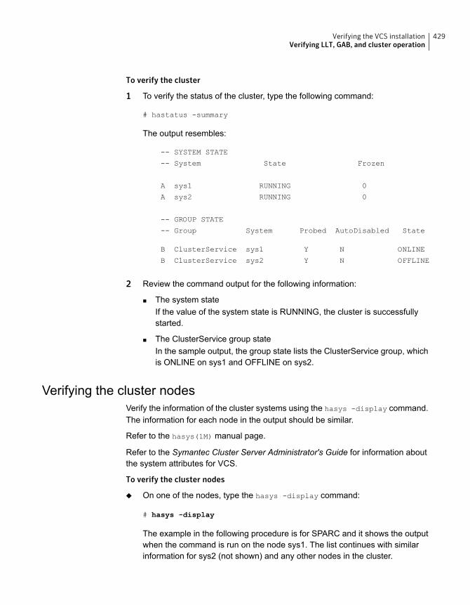
To verify the cluster
1 To verify the status of the cluster, type the following command:
# hastatus -summary
The output resembles:
-- SYSTEM STATE
-- System State Frozen
A sys1 RUNNING 0
A sys2 RUNNING 0
-- GROUP STATE
-- Group System Probed AutoDisabled State
B ClusterService sys1 Y N ONLINE
B ClusterService sys2 Y N OFFLINE
2 Review the command output for the following information:
■ The system stateIf the value of the system state is RUNNING, the cluster is successfullystarted.
■ The ClusterService group stateIn the sample output, the group state lists the ClusterService group, whichis ONLINE on sys1 and OFFLINE on sys2.
Verifying the cluster nodesVerify the information of the cluster systems using the hasys -display command.The information for each node in the output should be similar.
Refer to the hasys(1M) manual page.
Refer to the Symantec Cluster Server Administrator's Guide for information aboutthe system attributes for VCS.
To verify the cluster nodes
◆ On one of the nodes, type the hasys -display command:
# hasys -display
The example in the following procedure is for SPARC and it shows the outputwhen the command is run on the node sys1. The list continues with similarinformation for sys2 (not shown) and any other nodes in the cluster.
429Verifying the VCS installationVerifying LLT, GAB, and cluster operation
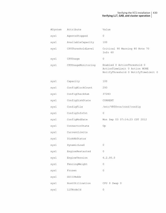
ValueAttribute#System
0AgentsStoppedsys1
100AvailableCapacitysys1
Critical 90 Warning 80 Note 70Info 60
CPUThresholdLevelsys1
0CPUUsagesys1
Enabled 0 ActionThreshold 0ActionTimeLimit 0 Action NONENotifyThreshold 0 NotifyTimeLimit 0
CPUUsageMonitoringsys1
100Capacitysys1
293ConfigBlockCountsys1
37283ConfigCheckSumsys1
CURRENTConfigDiskStatesys1
/etc/VRTSvcs/conf/configConfigFilesys1
0ConfigInfoCntsys1
Mon Sep 03 07:14:23 CDT 2012ConfigModDatesys1
UpConnectorStatesys1
CurrentLimitssys1
DiskHbStatussys1
0DynamicLoadsys1
0EngineRestartedsys1
6.2.00.0EngineVersionsys1
0FencingWeightsys1
0Frozensys1
GUIIPAddrsys1
CPU 0 Swap 0HostUtilizationsys1
0LLTNodeIdsys1
430Verifying the VCS installationVerifying LLT, GAB, and cluster operation
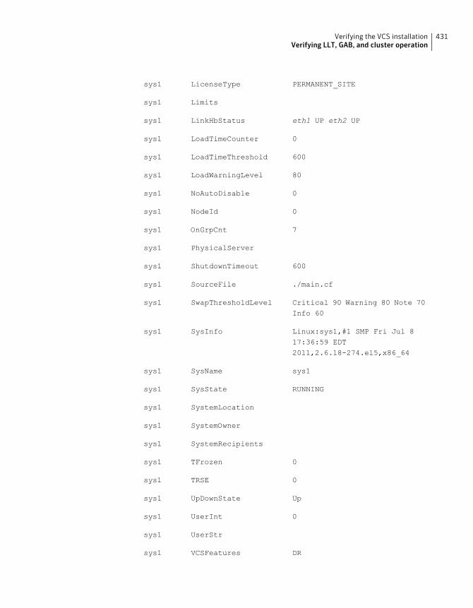
PERMANENT_SITELicenseTypesys1
Limitssys1
eth1 UP eth2 UPLinkHbStatussys1
0LoadTimeCountersys1
600LoadTimeThresholdsys1
80LoadWarningLevelsys1
0NoAutoDisablesys1
0NodeIdsys1
7OnGrpCntsys1
PhysicalServersys1
600ShutdownTimeoutsys1
./main.cfSourceFilesys1
Critical 90 Warning 80 Note 70Info 60
SwapThresholdLevelsys1
Linux:sys1,#1 SMP Fri Jul 817:36:59 EDT2011,2.6.18-274.el5,x86_64
SysInfosys1
sys1SysNamesys1
RUNNINGSysStatesys1
SystemLocationsys1
SystemOwnersys1
SystemRecipientssys1
0TFrozensys1
0TRSEsys1
UpUpDownStatesys1
0UserIntsys1
UserStrsys1
DRVCSFeaturessys1
431Verifying the VCS installationVerifying LLT, GAB, and cluster operation
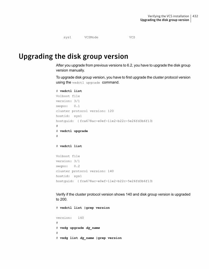
VCSVCSModesys1
Upgrading the disk group versionAfter you upgrade from previous versions to 6.2, you have to upgrade the disk groupversion manually.
To upgrade disk group version, you have to first upgrade the cluster protocol versionusing the vxdctl upgrade command.
# vxdctl list
Volboot file
version: 3/1
seqno: 0.1
cluster protocol version: 120
hostid: sys1
hostguid: {fca678ac-e0ef-11e2-b22c-5e26fd3b6f13}
#
# vxdctl upgrade
#
# vxdctl list
Volboot file
version: 3/1
seqno: 0.2
cluster protocol version: 140
hostid: sys1
hostguid: {fca678ac-e0ef-11e2-b22c-5e26fd3b6f13}
Verify if the cluster protocol version shows 140 and disk group version is upgradedto 200.
# vxdctl list |grep version
version: 140
#
# vxdg upgrade dg_name
#
# vxdg list dg_name |grep version
432Verifying the VCS installationUpgrading the disk group version
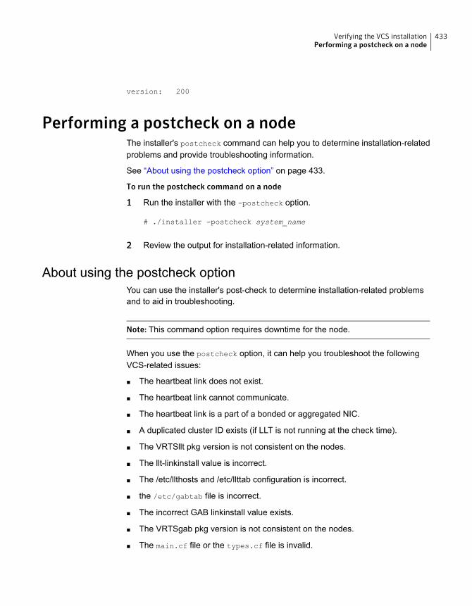
version: 200
Performing a postcheck on a nodeThe installer's postcheck command can help you to determine installation-relatedproblems and provide troubleshooting information.
See “About using the postcheck option” on page 433.
To run the postcheck command on a node
1 Run the installer with the -postcheck option.
# ./installer -postcheck system_name
2 Review the output for installation-related information.
About using the postcheck optionYou can use the installer's post-check to determine installation-related problemsand to aid in troubleshooting.
Note: This command option requires downtime for the node.
When you use the postcheck option, it can help you troubleshoot the followingVCS-related issues:
■ The heartbeat link does not exist.
■ The heartbeat link cannot communicate.
■ The heartbeat link is a part of a bonded or aggregated NIC.
■ A duplicated cluster ID exists (if LLT is not running at the check time).
■ The VRTSllt pkg version is not consistent on the nodes.
■ The llt-linkinstall value is incorrect.
■ The /etc/llthosts and /etc/llttab configuration is incorrect.
■ the /etc/gabtab file is incorrect.
■ The incorrect GAB linkinstall value exists.
■ The VRTSgab pkg version is not consistent on the nodes.
■ The main.cf file or the types.cf file is invalid.
433Verifying the VCS installationPerforming a postcheck on a node
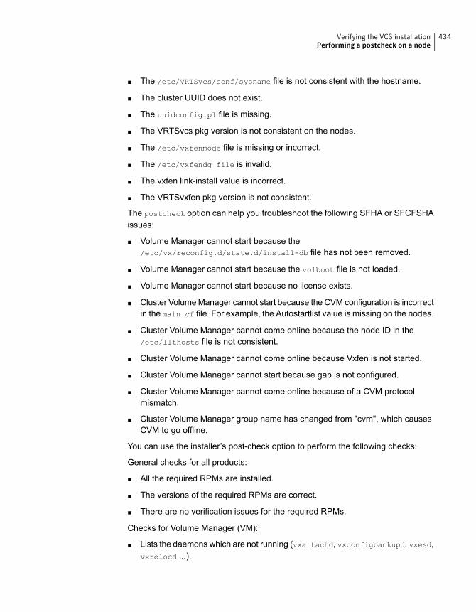
■ The /etc/VRTSvcs/conf/sysname file is not consistent with the hostname.
■ The cluster UUID does not exist.
■ The uuidconfig.pl file is missing.
■ The VRTSvcs pkg version is not consistent on the nodes.
■ The /etc/vxfenmode file is missing or incorrect.
■ The /etc/vxfendg file is invalid.
■ The vxfen link-install value is incorrect.
■ The VRTSvxfen pkg version is not consistent.
The postcheck option can help you troubleshoot the following SFHA or SFCFSHAissues:
■ Volume Manager cannot start because the/etc/vx/reconfig.d/state.d/install-db file has not been removed.
■ Volume Manager cannot start because the volboot file is not loaded.
■ Volume Manager cannot start because no license exists.
■ Cluster Volume Manager cannot start because the CVM configuration is incorrectin the main.cf file. For example, the Autostartlist value is missing on the nodes.
■ Cluster Volume Manager cannot come online because the node ID in the/etc/llthosts file is not consistent.
■ Cluster Volume Manager cannot come online because Vxfen is not started.
■ Cluster Volume Manager cannot start because gab is not configured.
■ Cluster Volume Manager cannot come online because of a CVM protocolmismatch.
■ Cluster Volume Manager group name has changed from "cvm", which causesCVM to go offline.
You can use the installer’s post-check option to perform the following checks:
General checks for all products:
■ All the required RPMs are installed.
■ The versions of the required RPMs are correct.
■ There are no verification issues for the required RPMs.
Checks for Volume Manager (VM):
■ Lists the daemons which are not running (vxattachd, vxconfigbackupd, vxesd,vxrelocd ...).
434Verifying the VCS installationPerforming a postcheck on a node
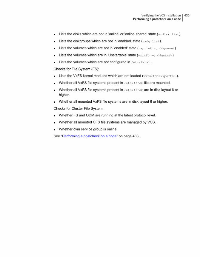
■ Lists the disks which are not in 'online' or 'online shared' state (vxdisk list).
■ Lists the diskgroups which are not in 'enabled' state (vxdg list).
■ Lists the volumes which are not in 'enabled' state (vxprint -g <dgname>).
■ Lists the volumes which are in 'Unstartable' state (vxinfo -g <dgname>).
■ Lists the volumes which are not configured in /etc/fstab .
Checks for File System (FS):
■ Lists the VxFS kernel modules which are not loaded (vxfs/fdd/vxportal.).
■ Whether all VxFS file systems present in /etc/fstab file are mounted.
■ Whether all VxFS file systems present in /etc/fstab are in disk layout 6 orhigher.
■ Whether all mounted VxFS file systems are in disk layout 6 or higher.
Checks for Cluster File System:
■ Whether FS and ODM are running at the latest protocol level.
■ Whether all mounted CFS file systems are managed by VCS.
■ Whether cvm service group is online.
See “Performing a postcheck on a node” on page 433.
435Verifying the VCS installationPerforming a postcheck on a node
Adding and removing clusternodes
■ Chapter 29. Adding a node to a single-node cluster
■ Chapter 30. Adding a node to a multi-node VCS cluster
■ Chapter 31. Removing a node from a VCS cluster
10Section
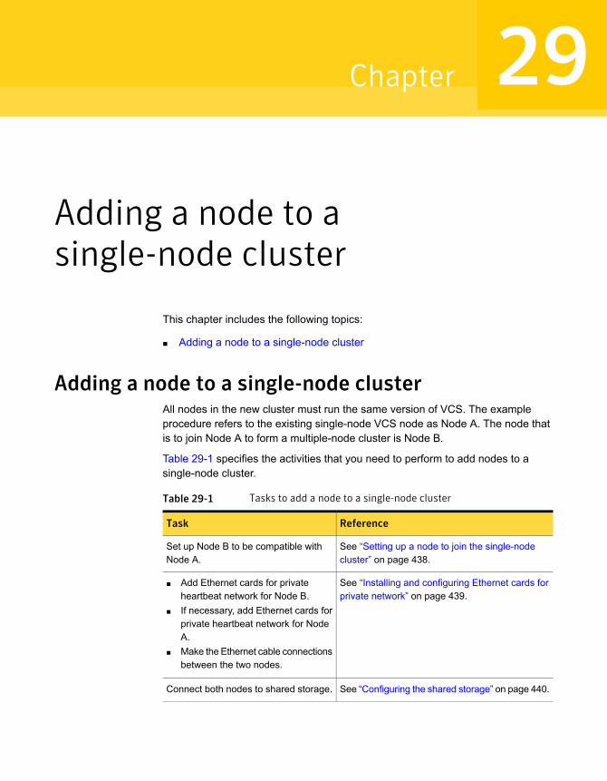
Adding a node to asingle-node cluster
This chapter includes the following topics:
■ Adding a node to a single-node cluster
Adding a node to a single-node clusterAll nodes in the new cluster must run the same version of VCS. The exampleprocedure refers to the existing single-node VCS node as Node A. The node thatis to join Node A to form a multiple-node cluster is Node B.
Table 29-1 specifies the activities that you need to perform to add nodes to asingle-node cluster.
Table 29-1 Tasks to add a node to a single-node cluster
ReferenceTask
See “Setting up a node to join the single-nodecluster” on page 438.
Set up Node B to be compatible withNode A.
See “Installing and configuring Ethernet cards forprivate network” on page 439.
■ Add Ethernet cards for privateheartbeat network for Node B.
■ If necessary, add Ethernet cards forprivate heartbeat network for NodeA.
■ Make the Ethernet cable connectionsbetween the two nodes.
See “Configuring the shared storage” on page 440.Connect both nodes to shared storage.
29Chapter

Table 29-1 Tasks to add a node to a single-node cluster (continued)
ReferenceTask
See “Bringing up the existing node” on page 440.■ Bring up VCS on Node A.■ Edit the configuration file.
See “Installing the VCS software manually whenadding a node to a single node cluster”on page 441.
If necessary, install VCS on Node B andadd a license key.
Make sure Node B is running the sameversion of VCS as the version on NodeA.
See “About the VCS configuration files”on page 505.
Edit the configuration files on Node B.
See “Starting LLT and GAB” on page 441.Start LLT and GAB on Node B.
See “Reconfiguring VCS on the existing node”on page 442.
■ Start LLT and GAB on Node A.■ Copy UUID from Node A to Node B.■ Restart VCS on Node A.■ Modify service groups for two nodes.
See “Verifying configuration on both nodes”on page 443.
■ Start VCS on Node B.■ Verify the two-node cluster.
Setting up a node to join the single-node clusterThe new node to join the existing single node that runs VCS must run the sameoperating system.
To set up a node to join the single-node cluster
1 Do one of the following tasks:
■ If VCS is not currently running on Node B, proceed to step 2.
■ If the node you plan to add as Node B is currently part of an existing cluster,remove the node from the cluster. After you remove the node from thecluster, remove the VCS RPMs and configuration files.See “Removing a node from a VCS cluster” on page 463.
■ If the node you plan to add as Node B is also currently a single VCS node,uninstall VCS.See “Uninstalling VCS using the script-based installer” on page 474.
■ If you renamed the LLT and GAB startup files, remove them.
438Adding a node to a single-node clusterAdding a node to a single-node cluster
2 If necessary, install VxVM and VxFS.
See “Installing VxVM or VxFS if necessary” on page 439.
Installing VxVM or VxFS if necessaryIf you have either VxVM or VxFS with the cluster option installed on the existingnode, install the same version on the new node.
Refer to the appropriate documentation for VxVM and VxFS to verify the versionsof the installed products. Make sure the same version runs on all nodes where youwant to use shared storage.
Installing and configuring Ethernet cards for private networkBoth nodes require Ethernet cards (NICs) that enable the private network. If bothNode A and Node B have Ethernet cards installed, you can ignore this step.
For high availability, use two separate NICs on each node. The two NICs provideredundancy for heartbeating.
See “Setting up the private network” on page 67.
To install and configure Ethernet cards for private network
1 Shut down VCS on Node A.
# hastop -local
2 Shut down the node to get to the OK prompt:
# shutdown -r now
3 Install the Ethernet card on Node A.
If you want to use aggregated interface to set up private network, configureaggregated interface.
4 Install the Ethernet card on Node B.
If you want to use aggregated interface to set up private network, configureaggregated interface.
5 Configure the Ethernet card on both nodes.
6 Make the two Ethernet cable connections from Node A to Node B for the privatenetworks.
7 Restart the nodes.
439Adding a node to a single-node clusterAdding a node to a single-node cluster
Configuring the shared storageMake the connection to shared storage from Node B. Configure VxVM on Node Band reboot the node when you are prompted.
See “Setting up shared storage” on page 70.
See “Setting up shared storage: Fibre Channel” on page 72.
Bringing up the existing nodeBring up the node.
To bring up the node
1 Restart Node A.
2 Log in as superuser.
3 Make the VCS configuration writable.
# haconf -makerw
4 Display the service groups currently configured.
# hagrp -list
5 Freeze the service groups.
# hagrp -freeze group -persistent
Repeat this command for each service group in step 4.
6 Make the configuration read-only.
# haconf -dump -makero
7 Stop VCS on Node A.
# hastop -local -force
440Adding a node to a single-node clusterAdding a node to a single-node cluster
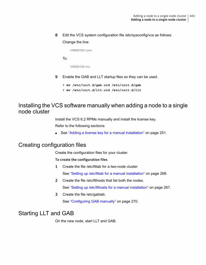
8 Edit the VCS system configuration file /etc/sysconfig/vcs as follows:
Change the line:
ONENODE=yes
To:
ONENODE=no
9 Enable the GAB and LLT startup files so they can be used.
# mv /etc/init.d/gab.old /etc/init.d/gab
# mv /etc/init.d/llt.old /etc/init.d/llt
Installing the VCS software manually when adding a node to a singlenode cluster
Install the VCS 6.2 RPMs manually and install the license key.
Refer to the following sections:
■ See “Adding a license key for a manual installation” on page 251.
Creating configuration filesCreate the configuration files for your cluster.
To create the configuration files
1 Create the file /etc/llttab for a two-node cluster
See “Setting up /etc/llttab for a manual installation” on page 268.
2 Create the file /etc/llthosts that list both the nodes.
See “Setting up /etc/llthosts for a manual installation” on page 267.
3 Create the file /etc/gabtab.
See “Configuring GAB manually” on page 270.
Starting LLT and GABOn the new node, start LLT and GAB.
441Adding a node to a single-node clusterAdding a node to a single-node cluster

To start LLT and GAB
1 Start LLT on Node B.
# /etc/init.d/llt start
2 Start GAB on Node B.
# /etc/init.d/gab start
Reconfiguring VCS on the existing nodeReconfigure VCS on the existing nodes.
To reconfigure VCS on existing nodes
1 On Node A, create the files /etc/llttab, /etc/llthosts, and /etc/gabtab. Use thefiles that are created on Node B as a guide, customizing the /etc/llttab for NodeA.
2 Start LLT on Node A.
# /etc/init.d/llt start
3 Start GAB on Node A.
# /etc/init.d/gab start
4 Check the membership of the cluster.
# gabconfig -a
5 Copy the cluster UUID from the existing node to the new node:
# /opt/VRTSvcs/bin/uuidconfig.pl -clus -copy -from_sys \
node_name_in_running_cluster -to_sys new_sys1 ... new_sysn
Where you are copying the cluster UUID from a node in the cluster(node_name_in_running_cluster) to systems from new_sys1 through new_sysnthat you want to join the cluster.
6 Start VCS on Node A.
# hastart
7 Make the VCS configuration writable.
# haconf -makerw
442Adding a node to a single-node clusterAdding a node to a single-node cluster

8 Add Node B to the cluster.
# hasys -add sysB
9 Add Node B to the system list of each service group.
■ List the service groups.
# hagrp -list
■ For each service group that is listed, add the node.
# hagrp -modify group SystemList -add sysB 1
Verifying configuration on both nodesVerify the configuration for the nodes.
To verify the nodes' configuration
1 On Node B, check the cluster membership.
# gabconfig -a
2 Start the VCS on Node B.
# hastart
3 Verify that VCS is up on both nodes.
# hastatus
4 List the service groups.
# hagrp -list
5 Unfreeze the service groups.
# hagrp -unfreeze group -persistent
6 Save the new two-node configuration.
# haconf -dump -makero
443Adding a node to a single-node clusterAdding a node to a single-node cluster

Adding a node to amulti-node VCS cluster
This chapter includes the following topics:
■ Adding nodes using the VCS installer
■ Adding a node using the web-based installer
■ Manually adding a node to a cluster
Adding nodes using the VCS installerThe VCS installer performs the following tasks:
■ Verifies that the node and the existing cluster meet communication requirements.
■ Verifies the products and RPMs installed on the new node.
■ Discovers the network interfaces on the new node and checks the interfacesettings.
■ Creates the following files on the new node:/etc/llttab
/etc/VRTSvcs/conf/sysname
■ Updates the following configuration files and copies them on the new node:/etc/llthosts
/etc/gabtab
/etc/VRTSvcs/conf/config/main.cf
■ Copies the following files from the existing cluster to the new node/etc/vxfenmode/etc/vxfendg
30Chapter
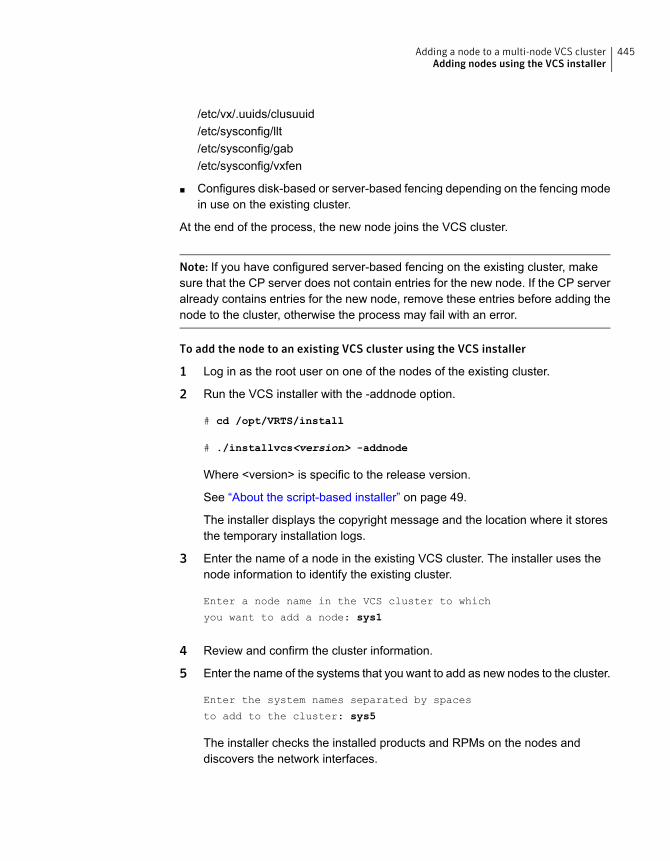
/etc/vx/.uuids/clusuuid/etc/sysconfig/llt/etc/sysconfig/gab/etc/sysconfig/vxfen
■ Configures disk-based or server-based fencing depending on the fencing modein use on the existing cluster.
At the end of the process, the new node joins the VCS cluster.
Note: If you have configured server-based fencing on the existing cluster, makesure that the CP server does not contain entries for the new node. If the CP serveralready contains entries for the new node, remove these entries before adding thenode to the cluster, otherwise the process may fail with an error.
To add the node to an existing VCS cluster using the VCS installer
1 Log in as the root user on one of the nodes of the existing cluster.
2 Run the VCS installer with the -addnode option.
# cd /opt/VRTS/install
# ./installvcs<version> -addnode
Where <version> is specific to the release version.
See “About the script-based installer” on page 49.
The installer displays the copyright message and the location where it storesthe temporary installation logs.
3 Enter the name of a node in the existing VCS cluster. The installer uses thenode information to identify the existing cluster.
Enter a node name in the VCS cluster to which
you want to add a node: sys1
4 Review and confirm the cluster information.
5 Enter the name of the systems that you want to add as new nodes to the cluster.
Enter the system names separated by spaces
to add to the cluster: sys5
The installer checks the installed products and RPMs on the nodes anddiscovers the network interfaces.
445Adding a node to a multi-node VCS clusterAdding nodes using the VCS installer
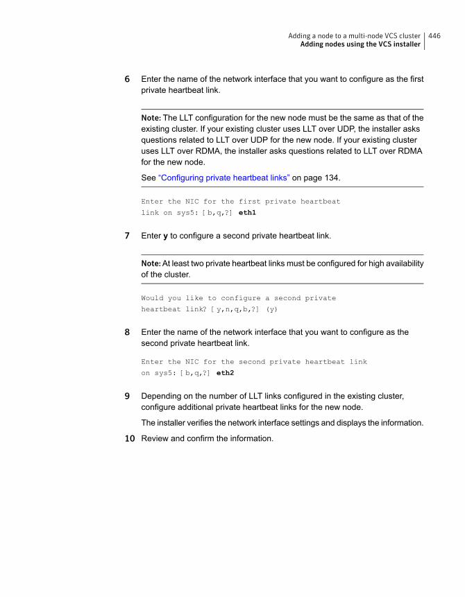
6 Enter the name of the network interface that you want to configure as the firstprivate heartbeat link.
Note: The LLT configuration for the new node must be the same as that of theexisting cluster. If your existing cluster uses LLT over UDP, the installer asksquestions related to LLT over UDP for the new node. If your existing clusteruses LLT over RDMA, the installer asks questions related to LLT over RDMAfor the new node.
See “Configuring private heartbeat links” on page 134.
Enter the NIC for the first private heartbeat
link on sys5: [b,q,?] eth1
7 Enter y to configure a second private heartbeat link.
Note:At least two private heartbeat links must be configured for high availabilityof the cluster.
Would you like to configure a second private
heartbeat link? [y,n,q,b,?] (y)
8 Enter the name of the network interface that you want to configure as thesecond private heartbeat link.
Enter the NIC for the second private heartbeat link
on sys5: [b,q,?] eth2
9 Depending on the number of LLT links configured in the existing cluster,configure additional private heartbeat links for the new node.
The installer verifies the network interface settings and displays the information.
10 Review and confirm the information.
446Adding a node to a multi-node VCS clusterAdding nodes using the VCS installer
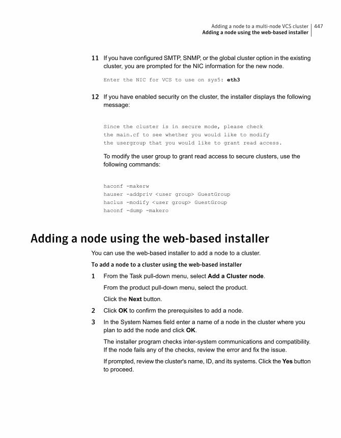
11 If you have configured SMTP, SNMP, or the global cluster option in the existingcluster, you are prompted for the NIC information for the new node.
Enter the NIC for VCS to use on sys5: eth3
12 If you have enabled security on the cluster, the installer displays the followingmessage:
Since the cluster is in secure mode, please check
the main.cf to see whether you would like to modify
the usergroup that you would like to grant read access.
To modify the user group to grant read access to secure clusters, use thefollowing commands:
haconf -makerw
hauser -addpriv <user group> GuestGroup
haclus -modify <user group> GuestGroup
haconf -dump -makero
Adding a node using the web-based installerYou can use the web-based installer to add a node to a cluster.
To add a node to a cluster using the web-based installer
1 From the Task pull-down menu, select Add a Cluster node.
From the product pull-down menu, select the product.
Click the Next button.
2 Click OK to confirm the prerequisites to add a node.
3 In the System Names field enter a name of a node in the cluster where youplan to add the node and click OK.
The installer program checks inter-system communications and compatibility.If the node fails any of the checks, review the error and fix the issue.
If prompted, review the cluster's name, ID, and its systems. Click the Yes buttonto proceed.
447Adding a node to a multi-node VCS clusterAdding a node using the web-based installer
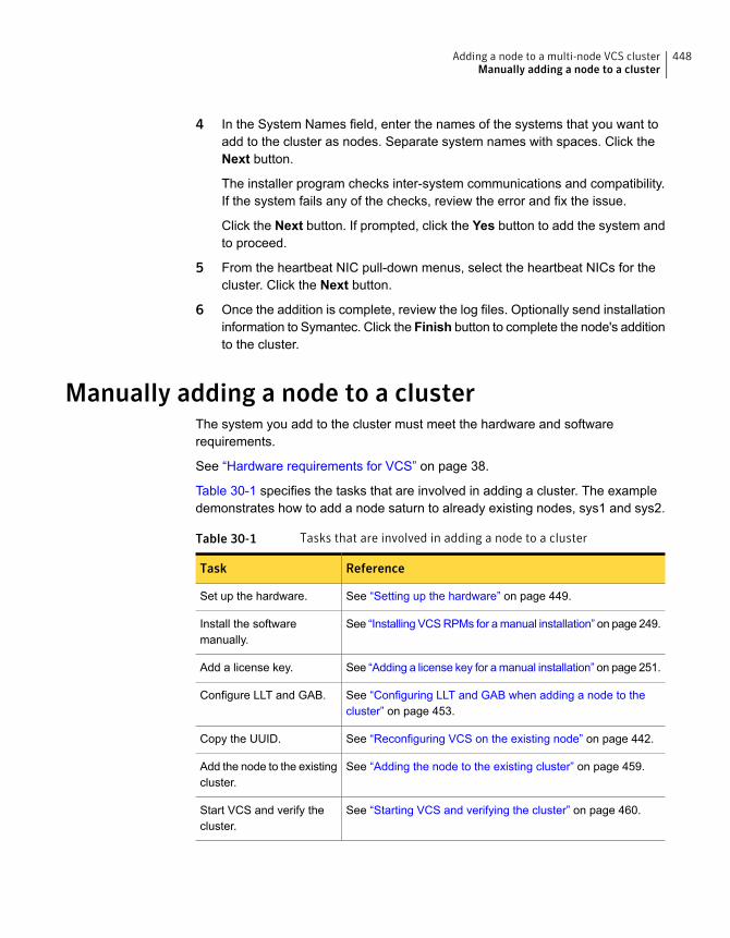
4 In the System Names field, enter the names of the systems that you want toadd to the cluster as nodes. Separate system names with spaces. Click theNext button.
The installer program checks inter-system communications and compatibility.If the system fails any of the checks, review the error and fix the issue.
Click the Next button. If prompted, click the Yes button to add the system andto proceed.
5 From the heartbeat NIC pull-down menus, select the heartbeat NICs for thecluster. Click the Next button.
6 Once the addition is complete, review the log files. Optionally send installationinformation to Symantec. Click the Finish button to complete the node's additionto the cluster.
Manually adding a node to a clusterThe system you add to the cluster must meet the hardware and softwarerequirements.
See “Hardware requirements for VCS” on page 38.
Table 30-1 specifies the tasks that are involved in adding a cluster. The exampledemonstrates how to add a node saturn to already existing nodes, sys1 and sys2.
Table 30-1 Tasks that are involved in adding a node to a cluster
ReferenceTask
See “Setting up the hardware” on page 449.Set up the hardware.
See “Installing VCS RPMs for a manual installation” on page 249.Install the softwaremanually.
See “Adding a license key for a manual installation” on page 251.Add a license key.
See “Configuring LLT and GAB when adding a node to thecluster” on page 453.
Configure LLT and GAB.
See “Reconfiguring VCS on the existing node” on page 442.Copy the UUID.
See “Adding the node to the existing cluster” on page 459.Add the node to the existingcluster.
See “Starting VCS and verifying the cluster” on page 460.Start VCS and verify thecluster.
448Adding a node to a multi-node VCS clusterManually adding a node to a cluster
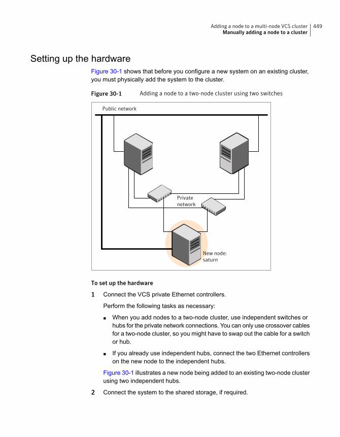
Setting up the hardwareFigure 30-1 shows that before you configure a new system on an existing cluster,you must physically add the system to the cluster.
Figure 30-1 Adding a node to a two-node cluster using two switches
Public network
Privatenetwork
New node:saturn
To set up the hardware
1 Connect the VCS private Ethernet controllers.
Perform the following tasks as necessary:
■ When you add nodes to a two-node cluster, use independent switches orhubs for the private network connections. You can only use crossover cablesfor a two-node cluster, so you might have to swap out the cable for a switchor hub.
■ If you already use independent hubs, connect the two Ethernet controllerson the new node to the independent hubs.
Figure 30-1 illustrates a new node being added to an existing two-node clusterusing two independent hubs.
2 Connect the system to the shared storage, if required.
449Adding a node to a multi-node VCS clusterManually adding a node to a cluster
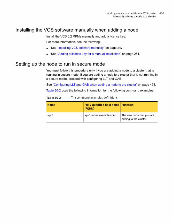
Installing the VCS software manually when adding a nodeInstall the VCS 6.2 RPMs manually and add a license key.
For more information, see the following:
■ See “Installing VCS software manually” on page 247.
■ See “Adding a license key for a manual installation” on page 251.
Setting up the node to run in secure modeYou must follow this procedure only if you are adding a node to a cluster that isrunning in secure mode. If you are adding a node to a cluster that is not running ina secure mode, proceed with configuring LLT and GAB.
See “Configuring LLT and GAB when adding a node to the cluster” on page 453.
Table 30-2 uses the following information for the following command examples.
Table 30-2 The command examples definitions
FunctionFully-qualified host name(FQHN)
Name
The new node that you areadding to the cluster.
sys5.nodes.example.comsys5
450Adding a node to a multi-node VCS clusterManually adding a node to a cluster
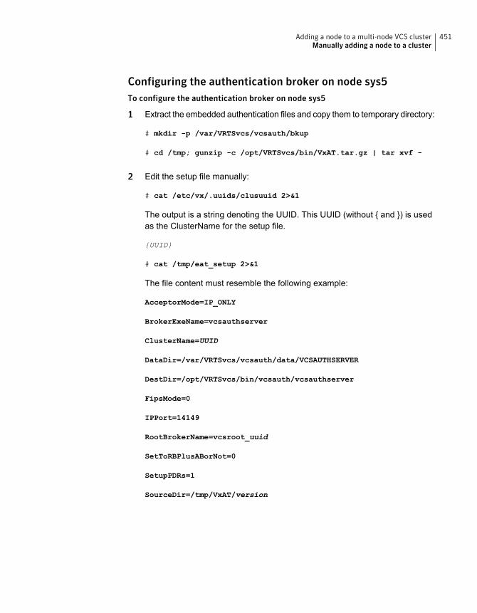
Configuring the authentication broker on node sys5To configure the authentication broker on node sys5
1 Extract the embedded authentication files and copy them to temporary directory:
# mkdir -p /var/VRTSvcs/vcsauth/bkup
# cd /tmp; gunzip -c /opt/VRTSvcs/bin/VxAT.tar.gz | tar xvf -
2 Edit the setup file manually:
# cat /etc/vx/.uuids/clusuuid 2>&1
The output is a string denoting the UUID. This UUID (without { and }) is usedas the ClusterName for the setup file.
{UUID}
# cat /tmp/eat_setup 2>&1
The file content must resemble the following example:
AcceptorMode=IP_ONLY
BrokerExeName=vcsauthserver
ClusterName=UUID
DataDir=/var/VRTSvcs/vcsauth/data/VCSAUTHSERVER
DestDir=/opt/VRTSvcs/bin/vcsauth/vcsauthserver
FipsMode=0
IPPort=14149
RootBrokerName=vcsroot_uuid
SetToRBPlusABorNot=0
SetupPDRs=1
SourceDir=/tmp/VxAT/version
451Adding a node to a multi-node VCS clusterManually adding a node to a cluster
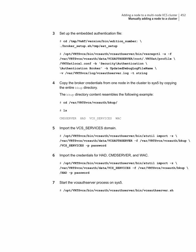
3 Set up the embedded authentication file:
# cd /tmp/VxAT/version/bin/edition_number; \
./broker_setup.sh/tmp/eat_setup
# /opt/VRTSvcs/bin/vcsauth/vcsauthserver/bin/vssregctl -s -f
/var/VRTSvcs/vcsauth/data/VCSAUTHSERVER/root/.VRTSat/profile \
/VRTSatlocal.conf -b 'Security\Authentication \
\Authentication Broker' -k UpdatedDebugLogFileName \
-v /var/VRTSvcs/log/vcsauthserver.log -t string
4 Copy the broker credentials from one node in the cluster to sys5 by copyingthe entire bkup directory.
The bkup directory content resembles the following example:
# cd /var/VRTSvcs/vcsauth/bkup/
# ls
CMDSERVER HAD VCS_SERVICES WAC
5 Import the VCS_SERVICES domain.
# /opt/VRTSvcs/bin/vcsauth/vcsauthserver/bin/atutil import -z \
/var/VRTSvcs/vcsauth/data/VCSAUTHSERVER -f /var/VRTSvcs/vcsauth/bkup \
/VCS_SERVICES -p password
6 Import the credentials for HAD, CMDSERVER, and WAC.
# /opt/VRTSvcs/bin/vcsauth/vcsauthserver/bin/atutil import -z \
/var/VRTSvcs/vcsauth/data/VCS_SERVICES -f /var/VRTSvcs/vcsauth/bkup \
/HAD -p password
7 Start the vcsauthserver process on sys5.
# /opt/VRTSvcs/bin/vcsauth/vcsauthserver/bin/vcsauthserver.sh
452Adding a node to a multi-node VCS clusterManually adding a node to a cluster
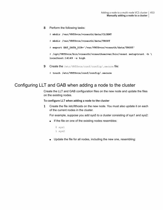
8 Perform the following tasks:
# mkdir /var/VRTSvcs/vcsauth/data/CLIENT
# mkdir /var/VRTSvcs/vcsauth/data/TRUST
# export EAT_DATA_DIR='/var/VRTSvcs/vcsauth/data/TRUST'
# /opt/VRTSvcs/bin/vcsauth/vcsauthserver/bin/vssat setuptrust -b \
localhost:14149 -s high
9 Create the /etc/VRTSvcs/conf/config/.secure file:
# touch /etc/VRTSvcs/conf/config/.secure
Configuring LLT and GAB when adding a node to the clusterCreate the LLT and GAB configuration files on the new node and update the fileson the existing nodes.
To configure LLT when adding a node to the cluster
1 Create the file /etc/llthosts on the new node. You must also update it on eachof the current nodes in the cluster.
For example, suppose you add sys5 to a cluster consisting of sys1 and sys2:
■ If the file on one of the existing nodes resembles:
0 sys1
1 sys2
■ Update the file for all nodes, including the new one, resembling:
453Adding a node to a multi-node VCS clusterManually adding a node to a cluster
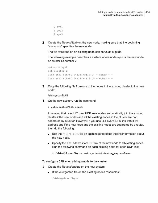
0 sys1
1 sys2
2 sys5
2 Create the file /etc/llttab on the new node, making sure that line beginning"set-node" specifies the new node.
The file /etc/llttab on an existing node can serve as a guide.
The following example describes a system where node sys2 is the new nodeon cluster ID number 2:
set-node sys2
set-cluster 2
link eth1 eth-00:04:23:AC:12:C4 - ether - -
link eth2 eth-00:04:23:AC:12:C5 - ether - -
3 Copy the following file from one of the nodes in the existing cluster to the newnode:
/etc/sysconfig/llt
4 On the new system, run the command:
# /etc/init.d/llt start
In a setup that uses LLT over UDP, new nodes automatically join the existingcluster if the new nodes and all the existing nodes in the cluster are notseparated by a router. However, if you use LLT over UDP6 link with IPv6address and if the new node and the existing nodes are separated by a router,then do the following:
■ Edit the /etc/llttab file on each node to reflect the link information aboutthe new node.
■ Specify the IPv6 address for UDP link of the new node to all existing nodes.Run the following command on each existing node for each UDP link:
# /sbin/lltconfig -a set systemid device_tag address
To configure GAB when adding a node to the cluster
1 Create the file /etc/gabtab on the new system.
■ If the /etc/gabtab file on the existing nodes resembles:
/sbin/gabconfig -c
454Adding a node to a multi-node VCS clusterManually adding a node to a cluster

The file on the new node should be the same. Symantec recommends thatyou use the -c -nN option, where N is the total number of cluster nodes.
■ If the /etc/gabtab file on the existing nodes resembles:
/sbin/gabconfig -c -n2
The file on all nodes, including the new node, should change to reflect thechange in the number of cluster nodes. For example, the new file on eachnode should resemble:
/sbin/gabconfig -c -n3
The -n flag indicates to VCS the number of nodes that must be ready toform a cluster before VCS starts.
2 Copy the following file from one of the nodes in the existing cluster to the newnode:
/etc/sysconfig/gab
3 On the new node, to configure GAB run the command:
# /etc/init.d/gab start
To verify GAB
1 On the new node, run the command:
# /sbin/gabconfig -a
The output should indicate that port a membership shows all nodes includingthe new node. The output should resemble:
GAB Port Memberships
====================================
Port a gen a3640003 membership 012
See “Verifying GAB” on page 427.
2 Run the same command on the other nodes (sys1 and sys2) to verify that theport a membership includes the new node:
# /sbin/gabconfig -a
GAB Port Memberships
====================================
Port a gen a3640003 membership 012
Port h gen fd570002 membership 01
Port h gen fd570002 visible ; 2
455Adding a node to a multi-node VCS clusterManually adding a node to a cluster
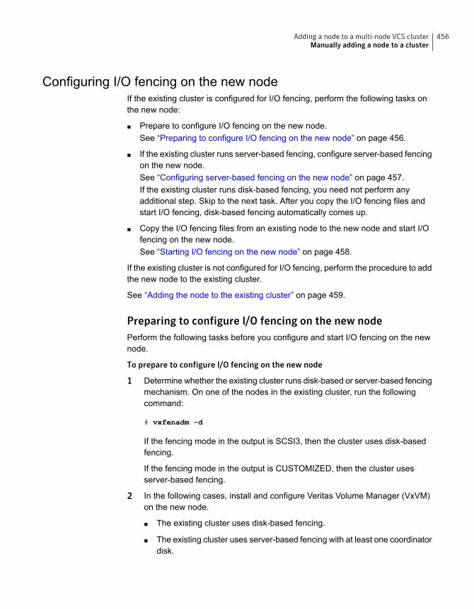
Configuring I/O fencing on the new nodeIf the existing cluster is configured for I/O fencing, perform the following tasks onthe new node:
■ Prepare to configure I/O fencing on the new node.See “Preparing to configure I/O fencing on the new node” on page 456.
■ If the existing cluster runs server-based fencing, configure server-based fencingon the new node.See “Configuring server-based fencing on the new node” on page 457.If the existing cluster runs disk-based fencing, you need not perform anyadditional step. Skip to the next task. After you copy the I/O fencing files andstart I/O fencing, disk-based fencing automatically comes up.
■ Copy the I/O fencing files from an existing node to the new node and start I/Ofencing on the new node.See “Starting I/O fencing on the new node” on page 458.
If the existing cluster is not configured for I/O fencing, perform the procedure to addthe new node to the existing cluster.
See “Adding the node to the existing cluster” on page 459.
Preparing to configure I/O fencing on the new nodePerform the following tasks before you configure and start I/O fencing on the newnode.
To prepare to configure I/O fencing on the new node
1 Determine whether the existing cluster runs disk-based or server-based fencingmechanism. On one of the nodes in the existing cluster, run the followingcommand:
# vxfenadm -d
If the fencing mode in the output is SCSI3, then the cluster uses disk-basedfencing.
If the fencing mode in the output is CUSTOMIZED, then the cluster usesserver-based fencing.
2 In the following cases, install and configure Veritas Volume Manager (VxVM)on the new node.
■ The existing cluster uses disk-based fencing.
■ The existing cluster uses server-based fencing with at least one coordinatordisk.
456Adding a node to a multi-node VCS clusterManually adding a node to a cluster
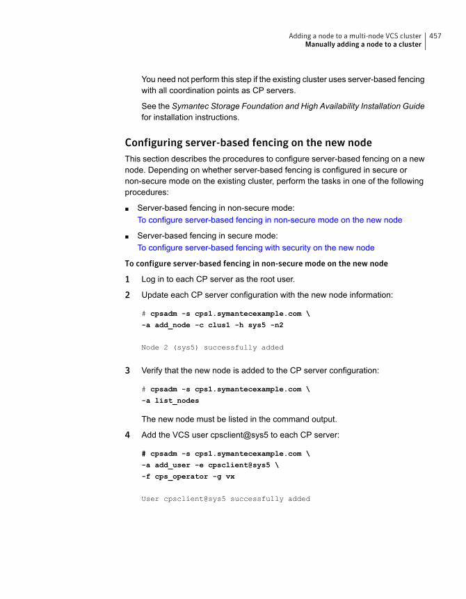
You need not perform this step if the existing cluster uses server-based fencingwith all coordination points as CP servers.
See the Symantec Storage Foundation and High Availability Installation Guidefor installation instructions.
Configuring server-based fencing on the new nodeThis section describes the procedures to configure server-based fencing on a newnode. Depending on whether server-based fencing is configured in secure ornon-secure mode on the existing cluster, perform the tasks in one of the followingprocedures:
■ Server-based fencing in non-secure mode:To configure server-based fencing in non-secure mode on the new node
■ Server-based fencing in secure mode:To configure server-based fencing with security on the new node
To configure server-based fencing in non-secure mode on the new node
1 Log in to each CP server as the root user.
2 Update each CP server configuration with the new node information:
# cpsadm -s cps1.symantecexample.com \
-a add_node -c clus1 -h sys5 -n2
Node 2 (sys5) successfully added
3 Verify that the new node is added to the CP server configuration:
# cpsadm -s cps1.symantecexample.com \
-a list_nodes
The new node must be listed in the command output.
4 Add the VCS user cpsclient@sys5 to each CP server:
# cpsadm -s cps1.symantecexample.com \
-a add_user -e cpsclient@sys5 \
-f cps_operator -g vx
User cpsclient@sys5 successfully added
457Adding a node to a multi-node VCS clusterManually adding a node to a cluster
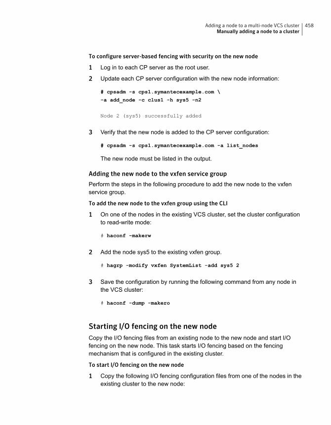
To configure server-based fencing with security on the new node
1 Log in to each CP server as the root user.
2 Update each CP server configuration with the new node information:
# cpsadm -s cps1.symantecexample.com \
-a add_node -c clus1 -h sys5 -n2
Node 2 (sys5) successfully added
3 Verify that the new node is added to the CP server configuration:
# cpsadm -s cps1.symantecexample.com -a list_nodes
The new node must be listed in the output.
Adding the new node to the vxfen service group
Perform the steps in the following procedure to add the new node to the vxfenservice group.
To add the new node to the vxfen group using the CLI
1 On one of the nodes in the existing VCS cluster, set the cluster configurationto read-write mode:
# haconf -makerw
2 Add the node sys5 to the existing vxfen group.
# hagrp -modify vxfen SystemList -add sys5 2
3 Save the configuration by running the following command from any node inthe VCS cluster:
# haconf -dump -makero
Starting I/O fencing on the new nodeCopy the I/O fencing files from an existing node to the new node and start I/Ofencing on the new node. This task starts I/O fencing based on the fencingmechanism that is configured in the existing cluster.
To start I/O fencing on the new node
1 Copy the following I/O fencing configuration files from one of the nodes in theexisting cluster to the new node:
458Adding a node to a multi-node VCS clusterManually adding a node to a cluster
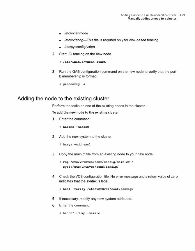
■ /etc/vxfenmode
■ /etc/vxfendg—This file is required only for disk-based fencing.
■ /etc/sysconfig/vxfen
2 Start I/O fencing on the new node.
# /etc/init.d/vxfen start
3 Run the GAB configuration command on the new node to verify that the portb membership is formed.
# gabconfig -a
Adding the node to the existing clusterPerform the tasks on one of the existing nodes in the cluster.
To add the new node to the existing cluster
1 Enter the command:
# haconf -makerw
2 Add the new system to the cluster:
# hasys -add sys1
3 Copy the main.cf file from an existing node to your new node:
# rcp /etc/VRTSvcs/conf/config/main.cf \
sys5:/etc/VRTSvcs/conf/config/
4 Check the VCS configuration file. No error message and a return value of zeroindicates that the syntax is legal.
# hacf -verify /etc/VRTSvcs/conf/config/
5 If necessary, modify any new system attributes.
6 Enter the command:
# haconf -dump -makero
459Adding a node to a multi-node VCS clusterManually adding a node to a cluster
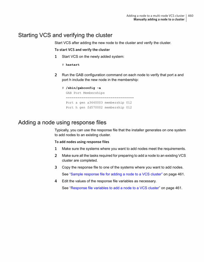
Starting VCS and verifying the clusterStart VCS after adding the new node to the cluster and verify the cluster.
To start VCS and verify the cluster
1 Start VCS on the newly added system:
# hastart
2 Run the GAB configuration command on each node to verify that port a andport h include the new node in the membership:
# /sbin/gabconfig -a
GAB Port Memberships
===================================
Port a gen a3640003 membership 012
Port h gen fd570002 membership 012
Adding a node using response filesTypically, you can use the response file that the installer generates on one systemto add nodes to an existing cluster.
To add nodes using response files
1 Make sure the systems where you want to add nodes meet the requirements.
2 Make sure all the tasks required for preparing to add a node to an existing VCScluster are completed.
3 Copy the response file to one of the systems where you want to add nodes.
See “Sample response file for adding a node to a VCS cluster” on page 461.
4 Edit the values of the response file variables as necessary.
See “Response file variables to add a node to a VCS cluster” on page 461.
460Adding a node to a multi-node VCS clusterManually adding a node to a cluster
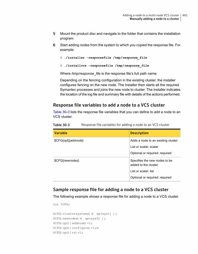
5 Mount the product disc and navigate to the folder that contains the installationprogram.
6 Start adding nodes from the system to which you copied the response file. Forexample:
# ./installer -responsefile /tmp/response_file
# ./installvcs -responsefile /tmp/response_file
Where /tmp/response_file is the response file’s full path name.
Depending on the fencing configuration in the existing cluster, the installerconfigures fencing on the new node. The installer then starts all the requiredSymantec processes and joins the new node to cluster. The installer indicatesthe location of the log file and summary file with details of the actions performed.
Response file variables to add a node to a VCS clusterTable 30-3 lists the response file variables that you can define to add a node to anVCS cluster.
Table 30-3 Response file variables for adding a node to an VCS cluster
DescriptionVariable
Adds a node to an existing cluster.
List or scalar: scalar
Optional or required: required
$CFG{opt}{addnode}
Specifies the new nodes to beadded to the cluster.
List or scalar: list
Optional or required: required
$CFG{newnodes}
Sample response file for adding a node to a VCS clusterThe following example shows a response file for adding a node to a VCS cluster.
our %CFG;
$CFG{clustersystems}=[ qw(sys1) ];
$CFG{newnodes}=[ qw(sys5) ];
$CFG{opt}{addnode}=1;
$CFG{opt}{configure}=1;d
$CFG{opt}{vr}=1;
461Adding a node to a multi-node VCS clusterManually adding a node to a cluster
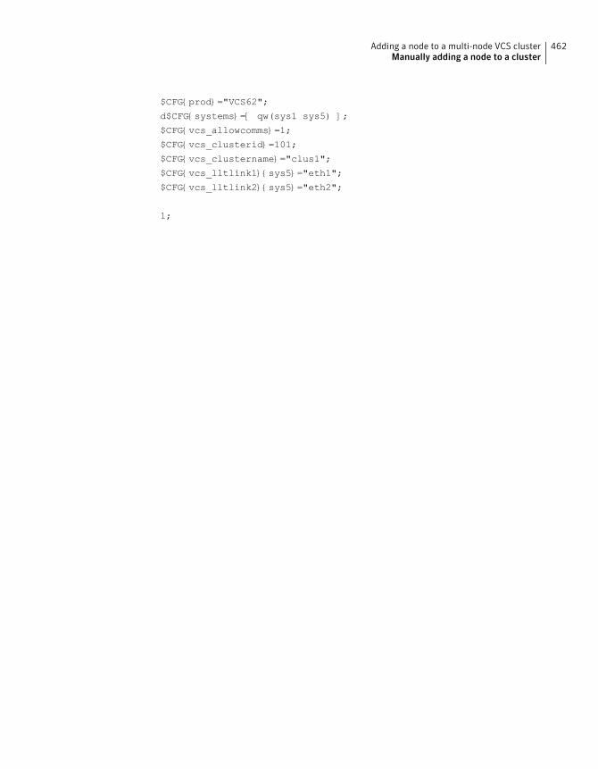
$CFG{prod}="VCS62";
d$CFG{systems}=[ qw(sys1 sys5) ];
$CFG{vcs_allowcomms}=1;
$CFG{vcs_clusterid}=101;
$CFG{vcs_clustername}="clus1";
$CFG{vcs_lltlink1}{sys5}="eth1";
$CFG{vcs_lltlink2}{sys5}="eth2";
1;
462Adding a node to a multi-node VCS clusterManually adding a node to a cluster
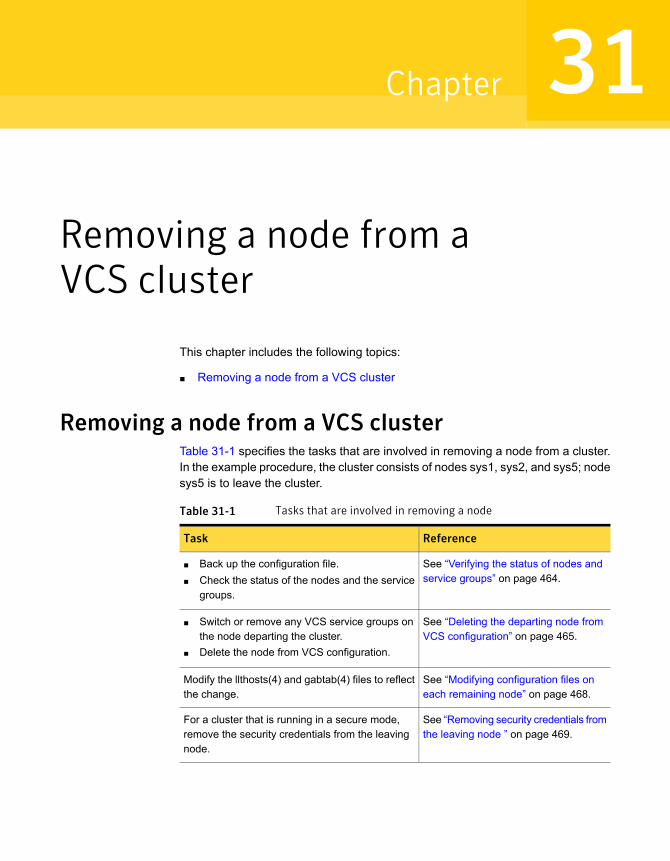
Removing a node from aVCS cluster
This chapter includes the following topics:
■ Removing a node from a VCS cluster
Removing a node from a VCS clusterTable 31-1 specifies the tasks that are involved in removing a node from a cluster.In the example procedure, the cluster consists of nodes sys1, sys2, and sys5; nodesys5 is to leave the cluster.
Table 31-1 Tasks that are involved in removing a node
ReferenceTask
See “Verifying the status of nodes andservice groups” on page 464.
■ Back up the configuration file.■ Check the status of the nodes and the service
groups.
See “Deleting the departing node fromVCS configuration” on page 465.
■ Switch or remove any VCS service groups onthe node departing the cluster.
■ Delete the node from VCS configuration.
See “Modifying configuration files oneach remaining node” on page 468.
Modify the llthosts(4) and gabtab(4) files to reflectthe change.
See “Removing security credentials fromthe leaving node ” on page 469.
For a cluster that is running in a secure mode,remove the security credentials from the leavingnode.
31Chapter
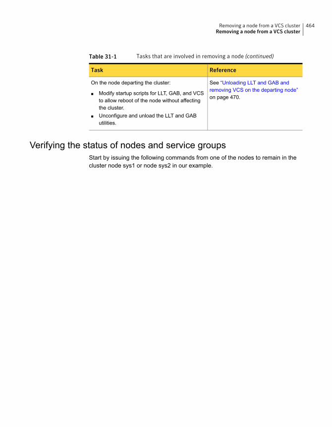
Table 31-1 Tasks that are involved in removing a node (continued)
ReferenceTask
See “Unloading LLT and GAB andremoving VCS on the departing node”on page 470.
On the node departing the cluster:
■ Modify startup scripts for LLT, GAB, and VCSto allow reboot of the node without affectingthe cluster.
■ Unconfigure and unload the LLT and GAButilities.
Verifying the status of nodes and service groupsStart by issuing the following commands from one of the nodes to remain in thecluster node sys1 or node sys2 in our example.
464Removing a node from a VCS clusterRemoving a node from a VCS cluster
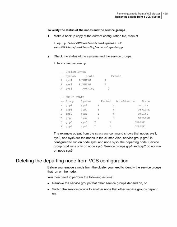
To verify the status of the nodes and the service groups
1 Make a backup copy of the current configuration file, main.cf.
# cp -p /etc/VRTSvcs/conf/config/main.cf\
/etc/VRTSvcs/conf/config/main.cf.goodcopy
2 Check the status of the systems and the service groups.
# hastatus -summary
-- SYSTEM STATE
-- System State Frozen
A sys1 RUNNING 0
A sys2 RUNNING 0
A sys5 RUNNING 0
-- GROUP STATE
-- Group System Probed AutoDisabled State
B grp1 sys1 Y N ONLINE
B grp1 sys2 Y N OFFLINE
B grp2 sys1 Y N ONLINE
B grp3 sys2 Y N OFFLINE
B grp3 sys5 Y N ONLINE
B grp4 sys5 Y N ONLINE
The example output from the hastatus command shows that nodes sys1,sys2, and sys5 are the nodes in the cluster. Also, service group grp3 isconfigured to run on node sys2 and node sys5, the departing node. Servicegroup grp4 runs only on node sys5. Service groups grp1 and grp2 do not runon node sys5.
Deleting the departing node from VCS configurationBefore you remove a node from the cluster you need to identify the service groupsthat run on the node.
You then need to perform the following actions:
■ Remove the service groups that other service groups depend on, or
■ Switch the service groups to another node that other service groups dependon.
465Removing a node from a VCS clusterRemoving a node from a VCS cluster
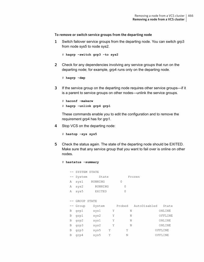
To remove or switch service groups from the departing node
1 Switch failover service groups from the departing node. You can switch grp3from node sys5 to node sys2.
# hagrp -switch grp3 -to sys2
2 Check for any dependencies involving any service groups that run on thedeparting node; for example, grp4 runs only on the departing node.
# hagrp -dep
3 If the service group on the departing node requires other service groups—if itis a parent to service groups on other nodes—unlink the service groups.
# haconf -makerw
# hagrp -unlink grp4 grp1
These commands enable you to edit the configuration and to remove therequirement grp4 has for grp1.
4 Stop VCS on the departing node:
# hastop -sys sys5
5 Check the status again. The state of the departing node should be EXITED.Make sure that any service group that you want to fail over is online on othernodes.
# hastatus -summary
-- SYSTEM STATE
-- System State Frozen
A sys1 RUNNING 0
A sys2 RUNNING 0
A sys5 EXITED 0
-- GROUP STATE
-- Group System Probed AutoDisabled State
B grp1 sys1 Y N ONLINE
B grp1 sys2 Y N OFFLINE
B grp2 sys1 Y N ONLINE
B grp3 sys2 Y N ONLINE
B grp3 sys5 Y Y OFFLINE
B grp4 sys5 Y N OFFLINE
466Removing a node from a VCS clusterRemoving a node from a VCS cluster
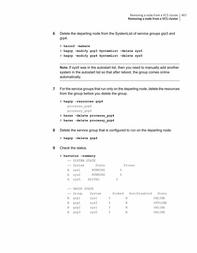
6 Delete the departing node from the SystemList of service groups grp3 andgrp4.
# haconf -makerw
# hagrp -modify grp3 SystemList -delete sys5
# hagrp -modify grp4 SystemList -delete sys5
Note: If sys5 was in the autostart list, then you need to manually add anothersystem in the autostart list so that after reboot, the group comes onlineautomatically.
7 For the service groups that run only on the departing node, delete the resourcesfrom the group before you delete the group.
# hagrp -resources grp4
processx_grp4
processy_grp4
# hares -delete processx_grp4
# hares -delete processy_grp4
8 Delete the service group that is configured to run on the departing node.
# hagrp -delete grp4
9 Check the status.
# hastatus -summary
-- SYSTEM STATE
-- System State Frozen
A sys1 RUNNING 0
A sys2 RUNNING 0
A sys5 EXITED 0
-- GROUP STATE
-- Group System Probed AutoDisabled State
B grp1 sys1 Y N ONLINE
B grp1 sys2 Y N OFFLINE
B grp2 sys1 Y N ONLINE
B grp3 sys2 Y N ONLINE
467Removing a node from a VCS clusterRemoving a node from a VCS cluster
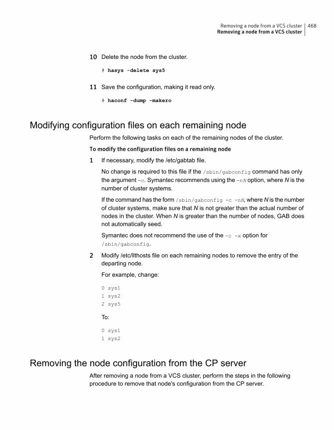
10 Delete the node from the cluster.
# hasys -delete sys5
11 Save the configuration, making it read only.
# haconf -dump -makero
Modifying configuration files on each remaining nodePerform the following tasks on each of the remaining nodes of the cluster.
To modify the configuration files on a remaining node
1 If necessary, modify the /etc/gabtab file.
No change is required to this file if the /sbin/gabconfig command has onlythe argument -c. Symantec recommends using the -nN option, where N is thenumber of cluster systems.
If the command has the form /sbin/gabconfig -c -nN, whereN is the numberof cluster systems, make sure that N is not greater than the actual number ofnodes in the cluster. When N is greater than the number of nodes, GAB doesnot automatically seed.
Symantec does not recommend the use of the -c -x option for/sbin/gabconfig.
2 Modify /etc/llthosts file on each remaining nodes to remove the entry of thedeparting node.
For example, change:
0 sys1
1 sys2
2 sys5
To:
0 sys1
1 sys2
Removing the node configuration from the CP serverAfter removing a node from a VCS cluster, perform the steps in the followingprocedure to remove that node's configuration from the CP server.
468Removing a node from a VCS clusterRemoving a node from a VCS cluster
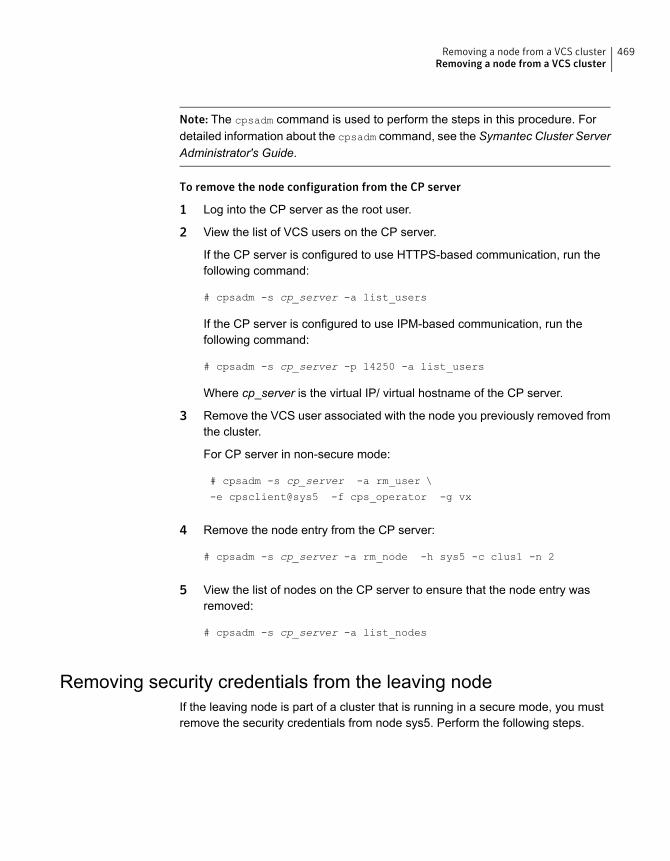
Note: The cpsadm command is used to perform the steps in this procedure. Fordetailed information about the cpsadm command, see the Symantec Cluster ServerAdministrator's Guide.
To remove the node configuration from the CP server
1 Log into the CP server as the root user.
2 View the list of VCS users on the CP server.
If the CP server is configured to use HTTPS-based communication, run thefollowing command:
# cpsadm -s cp_server -a list_users
If the CP server is configured to use IPM-based communication, run thefollowing command:
# cpsadm -s cp_server -p 14250 -a list_users
Where cp_server is the virtual IP/ virtual hostname of the CP server.
3 Remove the VCS user associated with the node you previously removed fromthe cluster.
For CP server in non-secure mode:
# cpsadm -s cp_server -a rm_user \
-e cpsclient@sys5 -f cps_operator -g vx
4 Remove the node entry from the CP server:
# cpsadm -s cp_server -a rm_node -h sys5 -c clus1 -n 2
5 View the list of nodes on the CP server to ensure that the node entry wasremoved:
# cpsadm -s cp_server -a list_nodes
Removing security credentials from the leaving nodeIf the leaving node is part of a cluster that is running in a secure mode, you mustremove the security credentials from node sys5. Perform the following steps.
469Removing a node from a VCS clusterRemoving a node from a VCS cluster
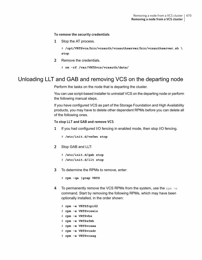
To remove the security credentials
1 Stop the AT process.
# /opt/VRTSvcs/bin/vcsauth/vcsauthserver/bin/vcsauthserver.sh \
stop
2 Remove the credentials.
# rm -rf /var/VRTSvcs/vcsauth/data/
Unloading LLT and GAB and removing VCS on the departing nodePerform the tasks on the node that is departing the cluster.
You can use script-based installer to uninstall VCS on the departing node or performthe following manual steps.
If you have configured VCS as part of the Storage Foundation and High Availabilityproducts, you may have to delete other dependent RPMs before you can delete allof the following ones.
To stop LLT and GAB and remove VCS
1 If you had configured I/O fencing in enabled mode, then stop I/O fencing.
# /etc/init.d/vxfen stop
2 Stop GAB and LLT:
# /etc/init.d/gab stop
# /etc/init.d/llt stop
3 To determine the RPMs to remove, enter:
# rpm -qa |grep VRTS
4 To permanently remove the VCS RPMs from the system, use the rpm -e
command. Start by removing the following RPMs, which may have beenoptionally installed, in the order shown:
# rpm -e VRTSfcpi62
# rpm -e VRTSvcswiz
# rpm -e VRTSvbs
# rpm -e VRTSsfmh
# rpm -e VRTSvcsea
# rpm -e VRTSvcsdr
# rpm -e VRTSvcsag
470Removing a node from a VCS clusterRemoving a node from a VCS cluster
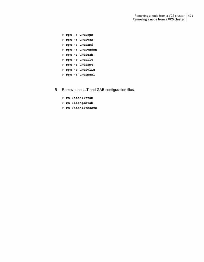
# rpm -e VRTScps
# rpm -e VRTSvcs
# rpm -e VRTSamf
# rpm -e VRTSvxfen
# rpm -e VRTSgab
# rpm -e VRTSllt
# rpm -e VRTSspt
# rpm -e VRTSvlic
# rpm -e VRTSperl
5 Remove the LLT and GAB configuration files.
# rm /etc/llttab
# rm /etc/gabtab
# rm /etc/llthosts
471Removing a node from a VCS clusterRemoving a node from a VCS cluster
Uninstallation of VCS
■ Chapter 32. Uninstalling VCS using the installer
■ Chapter 33. Uninstalling VCS using response files
■ Chapter 34. Manually uninstalling VCS
11Section
Uninstalling VCS using theinstaller
This chapter includes the following topics:
■ Preparing to uninstall VCS
■ Uninstalling VCS using the script-based installer
■ Uninstalling VCS with the web-based installer
■ Removing the CP server configuration using the installer program
Preparing to uninstall VCSReview the following prerequisites before you uninstall VCS:
■ Before you remove VCS from any node in the cluster, shut down the applicationsthat depend on VCS. For example, applications such as Java Console or anyhigh availability agents for VCS.
■ Before you remove VCS from fewer than all nodes in a cluster, stop the servicegroups on the nodes from which you uninstall VCS. You must also reconfigureVCS on the remaining nodes.See “Removing a node from a VCS cluster” on page 463.
■ If you have manually edited any of the VCS configuration files, you need toreformat them.See “Reformatting VCS configuration files on a stopped cluster” on page 78.
32Chapter
Uninstalling VCS using the script-based installerYou must meet the following conditions to use the uninstallvcs to uninstall VCS onall nodes in the cluster at one time:
■ Make sure that the communication exists between systems. By default, theuninstaller uses ssh.
■ Make sure you can execute ssh or rsh commands as superuser on all nodesin the cluster.
■ Make sure that the ssh or rsh is configured to operate without requests forpasswords or passphrases.
If you cannot meet the prerequisites, then you must run the uninstallvcs on eachnode in the cluster.
The uninstallvcs removes all VCS RPMs.
The following example demonstrates how to uninstall VCS using the uninstallvcs.The uninstallvcs uninstalls VCS on two nodes: sys1 sys2. The example procedureuninstalls VCS from all nodes in the cluster.
Note: If already present on the system, the uninstallation does not remove theVRTSacclib RPM.
Removing VCS 6.2 RPMsThe program stops the VCS processes that are currently running during theuninstallation process.
To uninstall VCS
1 Log in as superuser from the node where you want to uninstall VCS.
2 Start uninstallvcs.
# cd /opt/VRTS/install
# ./uninstallvcs<version>
Where <version> is the specific release version.
See “About the script-based installer” on page 49.
The program specifies the directory where the logs are created. The programdisplays a copyright notice and a description of the cluster:
474Uninstalling VCS using the installerUninstalling VCS using the script-based installer
3 Enter the names of the systems from which you want to uninstall VCS.
The program performs system verification checks and asks to stop all runningVCS processes. The installer lists all the RPMs that it will remove.
4 Enter y to stop all the VCS processes.
The program stops the VCS processes and proceeds with uninstalling thesoftware.
5 Review the output as the uninstallvcs continues to do the following:
■ Verifies the communication between systems
■ Checks the installations on each system to determine the RPMs to beuninstalled.
6 Review the output as the uninstaller stops processes, unloads kernel modules,and removes the RPMs.
7 Note the location of summary, response, and log files that the uninstaller createsafter removing all the RPMs.
Running uninstallvcs from the VCS 6.2 discYou may need to use the uninstallvcs on the VCS 6.2 disc in one of the followingcases:
■ You need to uninstall VCS after an incomplete installation.
■ The uninstallvcs is not available in /opt/VRTS/install.
If you mounted the installation media to /mnt, access the uninstallvcs by changingdirectory to:
cd /mnt/cluster_server/
./uninstallvcs
Uninstalling VCS with the web-based installerThis section describes how to uninstall using the web-based installer.
Note:After you uninstall the product, you cannot access any file systems you createdusing the default disk layout version in VCS 6.2 with a previous version of VCS.
475Uninstalling VCS using the installerUninstalling VCS with the web-based installer
To uninstall VCS
1 Perform the required steps to save any data that you want to preserve. Forexample, take backups of configuration files.
2 Start the web-based installer.
See “Starting the web-based installer” on page 189.
3 On the Select a task and a product page, select Uninstall a Product from theTask drop-down list.
4 Select Symantec Cluster Server from the Product drop-down list, and clickNext.
5 Indicate the systems on which to uninstall. Enter one or more system names,separated by spaces. Click Next.
6 After the validation completes successfully, click Next to uninstall VCS on theselected system.
7 If there are any processes running on the target system, the installer stops theprocesses. Click Next.
8 After the installer stops the processes, the installer removes the products fromthe specified system.
Click Next.
9 After the uninstall completes, the installer displays the location of the summary,response, and log files. If required, view the files to confirm the status of theremoval.
10 Click Finish.
Most RPMs have kernel components. To ensure their complete removal, asystem restart is recommended after all the RPMs have been removed.
Note: If already present on the system, the uninstallation does not remove theVRTSacclib RPM.
Removing the CP server configuration using theinstaller program
This section describes how to remove the CP server configuration from a node ora cluster that hosts the CP server.
476Uninstalling VCS using the installerRemoving the CP server configuration using the installer program
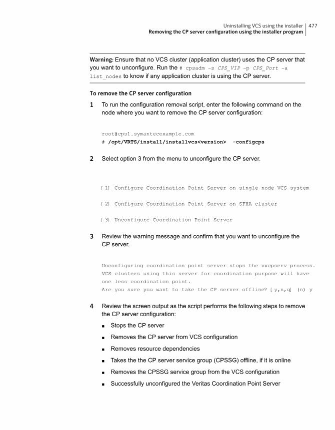
Warning: Ensure that no VCS cluster (application cluster) uses the CP server thatyou want to unconfigure. Run the # cpsadm -s CPS_VIP -p CPS_Port -a
list_nodes to know if any application cluster is using the CP server.
To remove the CP server configuration
1 To run the configuration removal script, enter the following command on thenode where you want to remove the CP server configuration:
# /opt/VRTS/install/installvcs<version> -configcps
2 Select option 3 from the menu to unconfigure the CP server.
[1] Configure Coordination Point Server on single node VCS system
[2] Configure Coordination Point Server on SFHA cluster
[3] Unconfigure Coordination Point Server
3 Review the warning message and confirm that you want to unconfigure theCP server.
Unconfiguring coordination point server stops the vxcpserv process.
VCS clusters using this server for coordination purpose will have
one less coordination point.
Are you sure you want to take the CP server offline? [y,n,q] (n) y
4 Review the screen output as the script performs the following steps to removethe CP server configuration:
■ Stops the CP server
■ Removes the CP server from VCS configuration
■ Removes resource dependencies
■ Takes the the CP server service group (CPSSG) offline, if it is online
■ Removes the CPSSG service group from the VCS configuration
■ Successfully unconfigured the Veritas Coordination Point Server
477Uninstalling VCS using the installerRemoving the CP server configuration using the installer program

The CP server database is not being deleted on the shared storage.
It can be re-used if CP server is reconfigured on the cluster.
The same database location can be specified during CP server
configuration.
5 Decide if you want to delete the CP server configuration file.
Do you want to delete the CP Server configuration file
(/etc/vxcps.conf) and log files
(in /var/VRTScps)? [y,n,q] (n) y
Deleting /etc/vxcps.conf and log files on sys1.... Done
Deleting /etc/vxcps.conf and log files on sys2... Done
6 Confirm if you want to send information about this installation to Symantec tohelp improve installation in the future.
Would you like to send the information about this installation
to Symantec to help improve installation in the future? [y,n,q,?] (y)
Upload completed successfully.
478Uninstalling VCS using the installerRemoving the CP server configuration using the installer program
Uninstalling VCS usingresponse files
This chapter includes the following topics:
■ Uninstalling VCS using response files
■ Response file variables to uninstall VCS
■ Sample response file for uninstalling VCS
Uninstalling VCS using response filesTypically, you can use the response file that the installer generates after you performVCS uninstallation on one cluster to uninstall VCS on other clusters.
To perform an automated uninstallation
1 Make sure that you meet the prerequisites to uninstall VCS.
2 Copy the response file to the system where you want to uninstall VCS.
See “Sample response file for uninstalling VCS” on page 481.
33Chapter
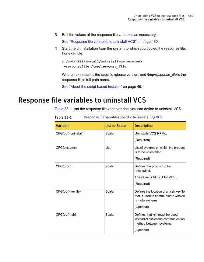
3 Edit the values of the response file variables as necessary.
See “Response file variables to uninstall VCS” on page 480.
4 Start the uninstallation from the system to which you copied the response file.For example:
# /opt/VRTS/install/uninstallvcs<version>
-responsefile /tmp/response_file
Where <version> is the specific release version, and /tmp/response_file is theresponse file’s full path name.
See “About the script-based installer” on page 49.
Response file variables to uninstall VCSTable 33-1 lists the response file variables that you can define to uninstall VCS.
Table 33-1 Response file variables specific to uninstalling VCS
DescriptionList or ScalarVariable
Uninstalls VCS RPMs.
(Required)
ScalarCFG{opt}{uninstall}
List of systems on which the productis to be uninstalled.
(Required)
ListCFG{systems}
Defines the product to beuninstalled.
The value is VCS61 for VCS.
(Required)
ScalarCFG{prod}
Defines the location of an ssh keyfilethat is used to communicate with allremote systems.
(Optional)
ScalarCFG{opt}{keyfile}
Defines that rsh must be usedinstead of ssh as the communicationmethod between systems.
(Optional)
ScalarCFG{opt}{rsh}
480Uninstalling VCS using response filesResponse file variables to uninstall VCS

Table 33-1 Response file variables specific to uninstalling VCS (continued)
DescriptionList or ScalarVariable
Mentions the location where the logfiles are to be copied. The defaultlocation is /opt/VRTS/install/logs.
Note: The installer copies theresponse files and summary filesalso to the specified logpathlocation.
(Optional)
ScalarCFG{opt}{logpath}
Sample response file for uninstalling VCSReview the response file variables and their definitions.
See “Response file variables to uninstall VCS” on page 480.
#
# Configuration Values:
#
our %CFG;
$CFG{opt}{uninstall}=1;
$CFG{prod}="VCS62";
$CFG{systems}=[ qw(sys1 sys2) ];
1;
481Uninstalling VCS using response filesSample response file for uninstalling VCS
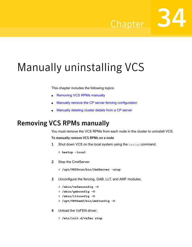
Manually uninstalling VCS
This chapter includes the following topics:
■ Removing VCS RPMs manually
■ Manually remove the CP server fencing configuration
■ Manually deleting cluster details from a CP server
Removing VCS RPMs manuallyYou must remove the VCS RPMs from each node in the cluster to uninstall VCS.
To manually remove VCS RPMs on a node
1 Shut down VCS on the local system using the hastop command.
# hastop -local
2 Stop the CmdServer.
# /opt/VRTSvcs/bin/CmdServer -stop
3 Unconfigure the fencing, GAB, LLT, and AMF modules.
# /sbin/vxfenconfig -U
# /sbin/gabconfig -U
# /sbin/lltconfig -U
# /opt/VRTSamf/bin/amfconfig -U
4 Unload the VxFEN driver:
# /etc/init.d/vxfen stop
34Chapter
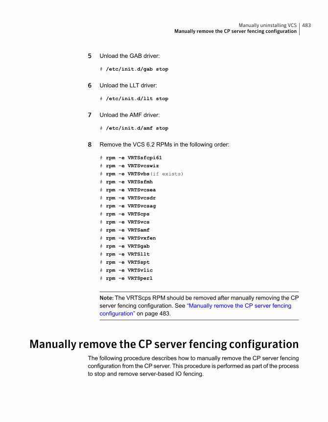
5 Unload the GAB driver:
# /etc/init.d/gab stop
6 Unload the LLT driver:
# /etc/init.d/llt stop
7 Unload the AMF driver:
# /etc/init.d/amf stop
8 Remove the VCS 6.2 RPMs in the following order:
# rpm -e VRTSsfcpi61
# rpm -e VRTSvcswiz
# rpm -e VRTSvbs(if exists)
# rpm -e VRTSsfmh
# rpm -e VRTSvcsea
# rpm -e VRTSvcsdr
# rpm -e VRTSvcsag
# rpm -e VRTScps
# rpm -e VRTSvcs
# rpm -e VRTSamf
# rpm -e VRTSvxfen
# rpm -e VRTSgab
# rpm -e VRTSllt
# rpm -e VRTSspt
# rpm -e VRTSvlic
# rpm -e VRTSperl
Note: The VRTScps RPM should be removed after manually removing the CPserver fencing configuration. See “Manually remove the CP server fencingconfiguration” on page 483.
Manually remove the CP server fencing configurationThe following procedure describes how to manually remove the CP server fencingconfiguration from the CP server. This procedure is performed as part of the processto stop and remove server-based IO fencing.
483Manually uninstalling VCSManually remove the CP server fencing configuration
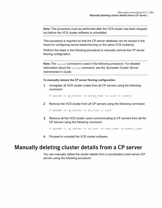
Note: This procedure must be performed after the VCS cluster has been stopped,but before the VCS cluster software is uninstalled.
This procedure is required so that the CP server database can be reused in thefuture for configuring server-based fencing on the same VCS cluster(s).
Perform the steps in the following procedure to manually remove the CP serverfencing configuration.
Note: The cpsadm command is used in the following procedure. For detailedinformation about the cpsadm command, see the Symantec Cluster ServerAdministrator's Guide.
To manually remove the CP server fencing configuration
1 Unregister all VCS cluster nodes from all CP servers using the followingcommand:
# cpsadm -s cp_server -a unreg_node -u uuid -n nodeid
2 Remove the VCS cluster from all CP servers using the following command:
# cpsadm -s cp_server -a rm_clus -u uuid
3 Remove all the VCS cluster users communicating to CP servers from all theCP servers using the following command:
# cpsadm -s cp_server -a rm_user -e user_name -g domain_type
4 Proceed to uninstall the VCS cluster software.
Manually deleting cluster details from a CP serverYou can manually delete the cluster details from a coordination point server (CPserver) using the following procedure.
484Manually uninstalling VCSManually deleting cluster details from a CP server

To manually delete cluster details from a CP server
1 List the nodes in the CP server cluster:
# cpsadm -s cps1 -a list_nodes
ClusterName UUID Hostname(Node ID) Registered
=========== =================================== ================ ===========
cluster1 {3719a60a-1dd2-11b2-b8dc-197f8305ffc0} node0(0) 1
2 List the CP server users:
# cpsadm -s cps1 -a list_users
Username/Domain Type Cluster Name/UUID Role
==================== ================== =======
cpsclient@hostname/vx cluster1/{3719a60a-1dd2-11b2-b8dc-197f8305ffc0} Operator
3 Remove the privileges for each user of the cluster that is listed in step 2 fromthe CP server cluster. For example:
# cpsadm -s cps1 -a rm_clus_from_user
-c cluster1 -e cpsclient@hostname -g vx -f cps_operator
Cluster successfully deleted from user cpsclient@hostname privileges.
4 Remove each user of the cluster that is listed in step 2. For example:
# cpsadm -s cps1 -a rm_user -e cpsclient@hostname -g vx
User cpsclient@hostname successfully deleted
5 Unregister each node that is registered to the CP server cluster. See the outputof step 1 for registered nodes. For example:
# cpsadm -s cps1 -a unreg_node -c cluster1 -n 0
Node 0 (node0) successfully unregistered
6 Remove each node from the CP server cluster. For example:
# cpsadm -s cps1 -a rm_node -c cluster1 -n 0
Node 0 (node0) successfully deleted
485Manually uninstalling VCSManually deleting cluster details from a CP server
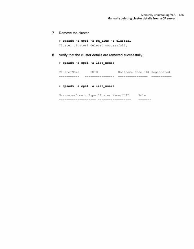
7 Remove the cluster.
# cpsadm -s cps1 -a rm_clus -c cluster1
Cluster cluster1 deleted successfully
8 Verify that the cluster details are removed successfully.
# cpsadm -s cps1 -a list_nodes
ClusterName UUID Hostname(Node ID) Registered
=========== ================ ================ ===========
# cpsadm -s cps1 -a list_users
Username/Domain Type Cluster Name/UUID Role
==================== ================== =======
486Manually uninstalling VCSManually deleting cluster details from a CP server

Installation reference
■ Appendix A. Services and ports
■ Appendix B. VCS installation RPMs
■ Appendix C. Installation command options
■ Appendix D. Configuration files
■ Appendix E. Installing VCS on a single node
■ Appendix F. Configuring LLT over UDP
■ Appendix G. Using LLT over RDMA
■ Appendix H. Configuring the secure shell or the remote shell for communications
■ Appendix I. Troubleshooting VCS installation
■ Appendix J. Sample VCS cluster setup diagrams for CP server-based I/O fencing
■ Appendix K. Compatibility issues when installing Symantec Cluster Server withother products
■ Appendix L. Upgrading the Steward process
12Section
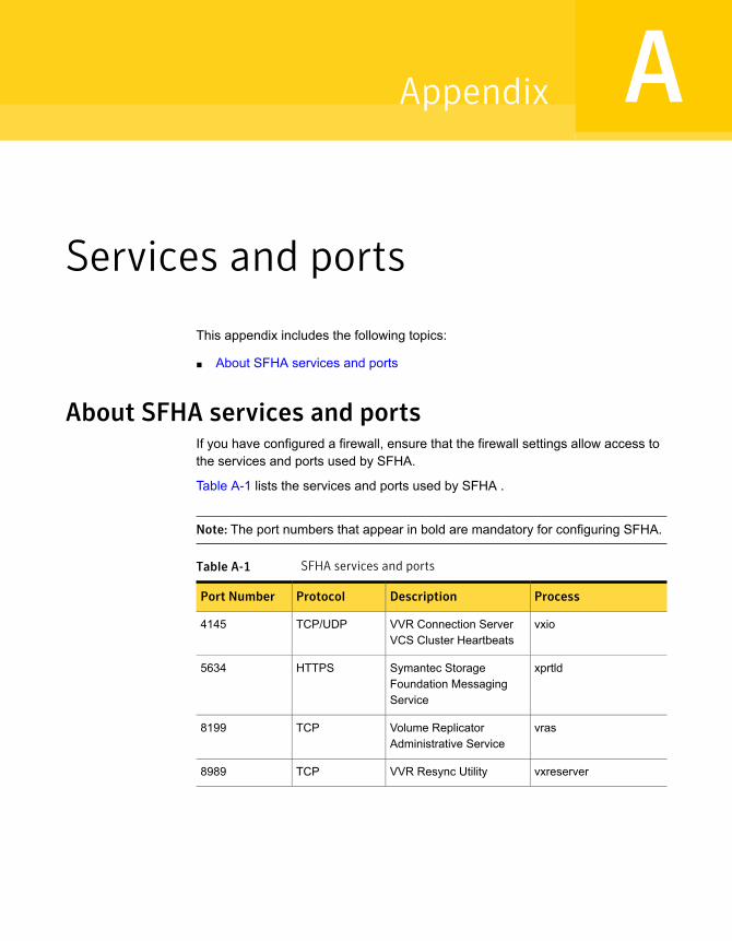
Services and ports
This appendix includes the following topics:
■ About SFHA services and ports
About SFHA services and portsIf you have configured a firewall, ensure that the firewall settings allow access tothe services and ports used by SFHA.
Table A-1 lists the services and ports used by SFHA .
Note: The port numbers that appear in bold are mandatory for configuring SFHA.
Table A-1 SFHA services and ports
ProcessDescriptionProtocolPort Number
vxioVVR Connection ServerVCS Cluster Heartbeats
TCP/UDP4145
xprtldSymantec StorageFoundation MessagingService
HTTPS5634
vrasVolume ReplicatorAdministrative Service
TCP8199
vxreserverVVR Resync UtilityTCP8989
AAppendix
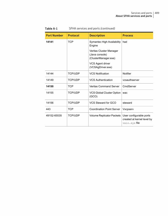
Table A-1 SFHA services and ports (continued)
ProcessDescriptionProtocolPort Number
hadSymantec High AvailabilityEngine
Veritas Cluster Manager(Java console)(ClusterManager.exe)
VCS Agent driver(VCSAgDriver.exe)
TCP14141
NotifierVCS NotificationTCP/UDP14144
vcsauthserverVCS AuthenticationTCP/UDP14149
CmdServerVeritas Command ServerTCP14150
wacVCS Global Cluster Option(GCO)
TCP/UDP14155
stewardVCS Steward for GCOTCP/UDP14156
VxcpservCoordination Point ServerTCP443
User configurable portscreated at kernel level byvxio.sys file
Volume Replicator PacketsTCP/UDP49152-65535
489Services and portsAbout SFHA services and ports
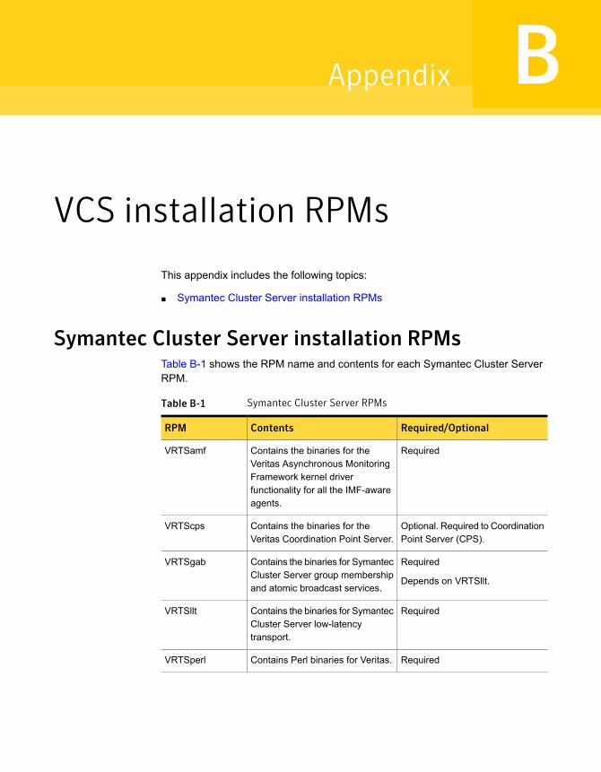
VCS installation RPMs
This appendix includes the following topics:
■ Symantec Cluster Server installation RPMs
Symantec Cluster Server installation RPMsTable B-1 shows the RPM name and contents for each Symantec Cluster ServerRPM.
Table B-1 Symantec Cluster Server RPMs
Required/OptionalContentsRPM
RequiredContains the binaries for theVeritas Asynchronous MonitoringFramework kernel driverfunctionality for all the IMF-awareagents.
VRTSamf
Optional. Required to CoordinationPoint Server (CPS).
Contains the binaries for theVeritas Coordination Point Server.
VRTScps
Required
Depends on VRTSllt.
Contains the binaries for SymantecCluster Server group membershipand atomic broadcast services.
VRTSgab
RequiredContains the binaries for SymantecCluster Server low-latencytransport.
VRTSllt
RequiredContains Perl binaries for Veritas.VRTSperl
BAppendix
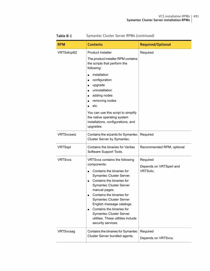
Table B-1 Symantec Cluster Server RPMs (continued)
Required/OptionalContentsRPM
RequiredProduct Installer
The product installer RPM containsthe scripts that perform thefollowing:
■ installation■ configuration■ upgrade■ uninstallation■ adding nodes■ removing nodes■ etc.
You can use this script to simplifythe native operating systeminstallations, configurations, andupgrades.
VRTSsfcpi62
RequiredContains the wizards for SymantecCluster Server by Symantec.
VRTSvcswiz
Recommended RPM, optionalContains the binaries for VeritasSoftware Support Tools.
VRTSspt
Required
Depends on VRTSperl andVRTSvlic.
VRTSvcs contains the followingcomponents:
■ Contains the binaries forSymantec Cluster Server.
■ Contains the binaries forSymantec Cluster Servermanual pages.
■ Contains the binaries forSymantec Cluster ServerEnglish message catalogs.
■ Contains the binaries forSymantec Cluster Serverutilities. These utilities includesecurity services.
VRTSvcs
Required
Depends on VRTSvcs.
Contains the binaries for SymantecCluster Server bundled agents.
VRTSvcsag
491VCS installation RPMsSymantec Cluster Server installation RPMs
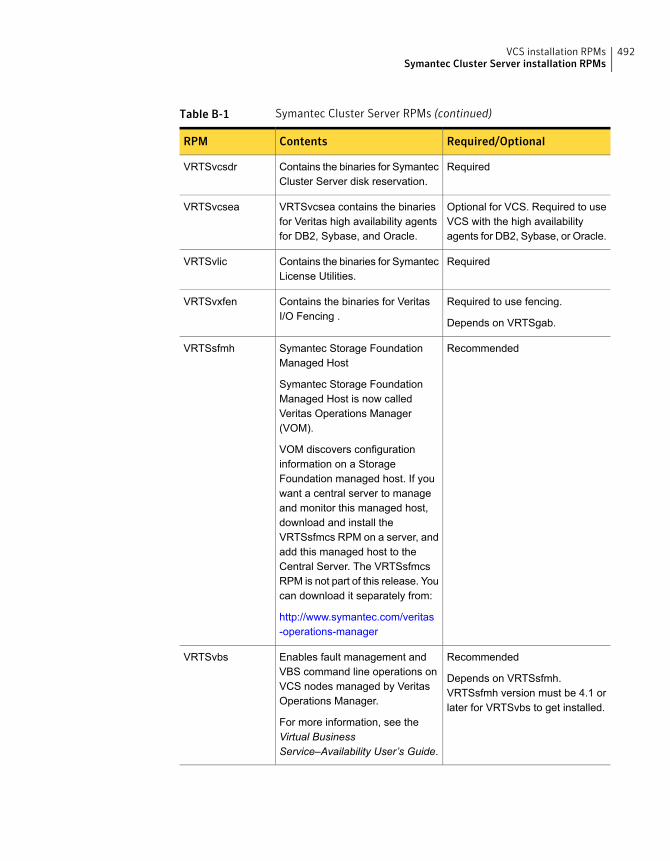
Table B-1 Symantec Cluster Server RPMs (continued)
Required/OptionalContentsRPM
RequiredContains the binaries for SymantecCluster Server disk reservation.
VRTSvcsdr
Optional for VCS. Required to useVCS with the high availabilityagents for DB2, Sybase, or Oracle.
VRTSvcsea contains the binariesfor Veritas high availability agentsfor DB2, Sybase, and Oracle.
VRTSvcsea
RequiredContains the binaries for SymantecLicense Utilities.
VRTSvlic
Required to use fencing.
Depends on VRTSgab.
Contains the binaries for VeritasI/O Fencing .
VRTSvxfen
RecommendedSymantec Storage FoundationManaged Host
Symantec Storage FoundationManaged Host is now calledVeritas Operations Manager(VOM).
VOM discovers configurationinformation on a StorageFoundation managed host. If youwant a central server to manageand monitor this managed host,download and install theVRTSsfmcs RPM on a server, andadd this managed host to theCentral Server. The VRTSsfmcsRPM is not part of this release. Youcan download it separately from:
http://www.symantec.com/veritas-operations-manager
VRTSsfmh
Recommended
Depends on VRTSsfmh.VRTSsfmh version must be 4.1 orlater for VRTSvbs to get installed.
Enables fault management andVBS command line operations onVCS nodes managed by VeritasOperations Manager.
For more information, see theVirtual BusinessService–Availability User’s Guide.
VRTSvbs
492VCS installation RPMsSymantec Cluster Server installation RPMs
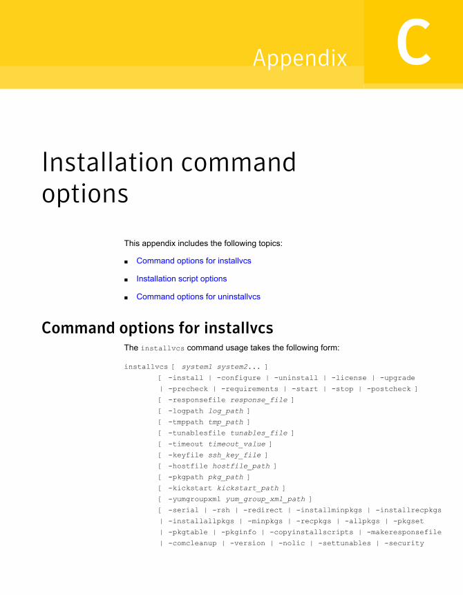
Installation commandoptions
This appendix includes the following topics:
■ Command options for installvcs
■ Installation script options
■ Command options for uninstallvcs
Command options for installvcsThe installvcs command usage takes the following form:
installvcs [ system1 system2... ]
[ -install | -configure | -uninstall | -license | -upgrade
| -precheck | -requirements | -start | -stop | -postcheck ]
[ -responsefile response_file ]
[ -logpath log_path ]
[ -tmppath tmp_path ]
[ -tunablesfile tunables_file ]
[ -timeout timeout_value ]
[ -keyfile ssh_key_file ]
[ -hostfile hostfile_path ]
[ -pkgpath pkg_path ]
[ -kickstart kickstart_path ]
[ -yumgroupxml yum_group_xml_path ]
[ -serial | -rsh | -redirect | -installminpkgs | -installrecpkgs
| -installallpkgs | -minpkgs | -recpkgs | -allpkgs | -pkgset
| -pkgtable | -pkginfo | -copyinstallscripts | -makeresponsefile
| -comcleanup | -version | -nolic | -settunables | -security
CAppendix
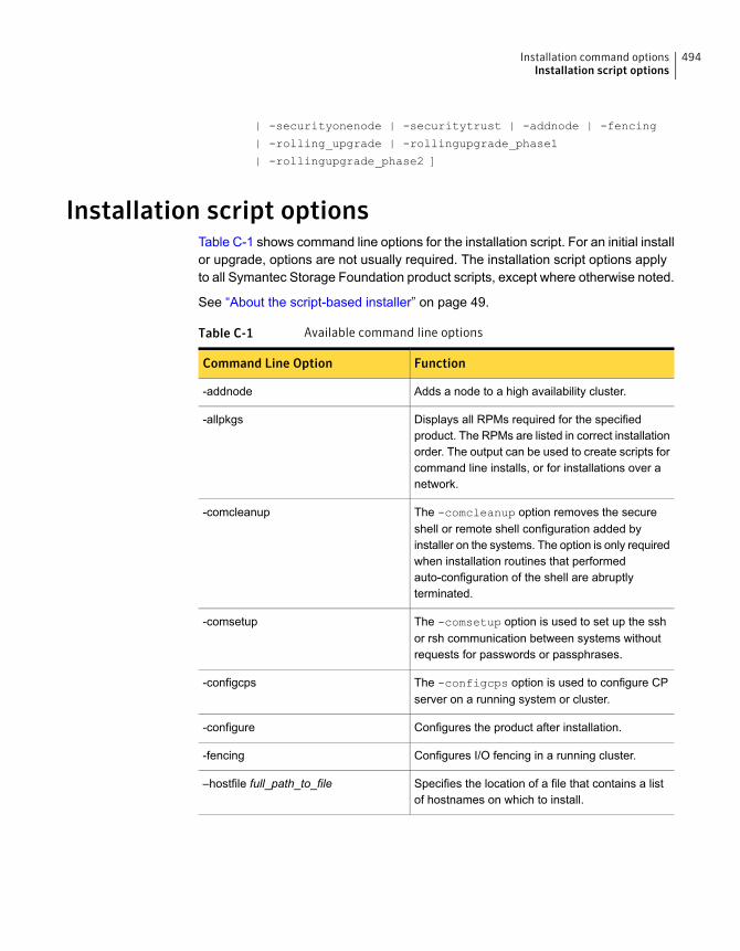
| -securityonenode | -securitytrust | -addnode | -fencing
| -rolling_upgrade | -rollingupgrade_phase1
| -rollingupgrade_phase2 ]
Installation script optionsTable C-1 shows command line options for the installation script. For an initial installor upgrade, options are not usually required. The installation script options applyto all Symantec Storage Foundation product scripts, except where otherwise noted.
See “About the script-based installer” on page 49.
Table C-1 Available command line options
FunctionCommand Line Option
Adds a node to a high availability cluster.-addnode
Displays all RPMs required for the specifiedproduct. The RPMs are listed in correct installationorder. The output can be used to create scripts forcommand line installs, or for installations over anetwork.
-allpkgs
The -comcleanup option removes the secureshell or remote shell configuration added byinstaller on the systems. The option is only requiredwhen installation routines that performedauto-configuration of the shell are abruptlyterminated.
-comcleanup
The -comsetup option is used to set up the sshor rsh communication between systems withoutrequests for passwords or passphrases.
-comsetup
The -configcps option is used to configure CPserver on a running system or cluster.
-configcps
Configures the product after installation.-configure
Configures I/O fencing in a running cluster.-fencing
Specifies the location of a file that contains a listof hostnames on which to install.
–hostfile full_path_to_file
494Installation command optionsInstallation script options
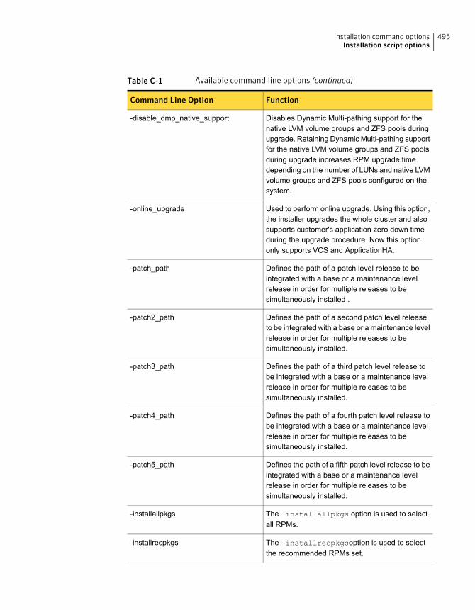
Table C-1 Available command line options (continued)
FunctionCommand Line Option
Disables Dynamic Multi-pathing support for thenative LVM volume groups and ZFS pools duringupgrade. Retaining Dynamic Multi-pathing supportfor the native LVM volume groups and ZFS poolsduring upgrade increases RPM upgrade timedepending on the number of LUNs and native LVMvolume groups and ZFS pools configured on thesystem.
-disable_dmp_native_support
Used to perform online upgrade. Using this option,the installer upgrades the whole cluster and alsosupports customer's application zero down timeduring the upgrade procedure. Now this optiononly supports VCS and ApplicationHA.
-online_upgrade
Defines the path of a patch level release to beintegrated with a base or a maintenance levelrelease in order for multiple releases to besimultaneously installed .
-patch_path
Defines the path of a second patch level releaseto be integrated with a base or a maintenance levelrelease in order for multiple releases to besimultaneously installed.
-patch2_path
Defines the path of a third patch level release tobe integrated with a base or a maintenance levelrelease in order for multiple releases to besimultaneously installed.
-patch3_path
Defines the path of a fourth patch level release tobe integrated with a base or a maintenance levelrelease in order for multiple releases to besimultaneously installed.
-patch4_path
Defines the path of a fifth patch level release to beintegrated with a base or a maintenance levelrelease in order for multiple releases to besimultaneously installed.
-patch5_path
The -installallpkgs option is used to selectall RPMs.
-installallpkgs
The -installrecpkgsoption is used to selectthe recommended RPMs set.
-installrecpkgs
495Installation command optionsInstallation script options

Table C-1 Available command line options (continued)
FunctionCommand Line Option
The -installminpkgsoption is used to selectthe minimum RPMs set.
–installminpkgs
The -ignorepatchreqs option is used to allowinstallation or upgrading even if the prerequisiteRPMs or patches are missed on the system.
-ignorepatchreqs
Specifies a key file for secure shell (SSH) installs.This option passes -I ssh_key_file to everySSH invocation.
–keyfile ssh_key_file
Produces a kickstart configuration file for installingwith Linux RHEL Kickstart. The file contains thelist of Symantec RPMs in the correct order forinstalling, in a format that can be used for Kickstartinstallations. The dir_path indicates the path to thedirectory in which to create the file.
–kickstart dir_path
Registers or updates product licenses on thespecified systems.
-license
Specifies a directory other than/opt/VRTS/install/logs as the locationwhere installer log files, summary files, andresponse files are saved.
–logpath log_path
Use the -makeresponsefile option only togenerate response files. No actual softwareinstallation occurs when you use this option.
-makeresponsefile
Displays the minimal RPMs required for thespecified product. The RPMs are listed in correctinstallation order. Optional RPMs are not listed.The output can be used to create scripts forcommand line installs, or for installations over anetwork. See allpkgs option.
-minpkgs
Disables the installer from making outboundnetworking calls to Symantec OperationsReadiness Tool (SORT) in order to automaticallyobtain patch and release information updates.
-noipc
496Installation command optionsInstallation script options
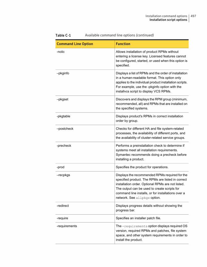
Table C-1 Available command line options (continued)
FunctionCommand Line Option
Allows installation of product RPMs withoutentering a license key. Licensed features cannotbe configured, started, or used when this option isspecified.
-nolic
Displays a list of RPMs and the order of installationin a human-readable format. This option onlyapplies to the individual product installation scripts.For example, use the -pkginfo option with theinstallvcs script to display VCS RPMs.
–pkginfo
Discovers and displays the RPM group (minimum,recommended, all) and RPMs that are installed onthe specified systems.
–pkgset
Displays product's RPMs in correct installationorder by group.
-pkgtable
Checks for different HA and file system-relatedprocesses, the availability of different ports, andthe availability of cluster-related service groups.
–postcheck
Performs a preinstallation check to determine ifsystems meet all installation requirements.Symantec recommends doing a precheck beforeinstalling a product.
-precheck
Specifies the product for operations.-prod
Displays the recommended RPMs required for thespecified product. The RPMs are listed in correctinstallation order. Optional RPMs are not listed.The output can be used to create scripts forcommand line installs, or for installations over anetwork. See allpkgs option.
–recpkgs
Displays progress details without showing theprogress bar.
-redirect
Specifies an installer patch file.-require
The -requirements option displays required OSversion, required RPMs and patches, file systemspace, and other system requirements in order toinstall the product.
-requirements
497Installation command optionsInstallation script options

Table C-1 Available command line options (continued)
FunctionCommand Line Option
Automates installation and configuration by usingsystem and configuration information stored in aspecified file instead of prompting for information.The response_file must be a full path name. Youmust edit the response file to use it for subsequentinstallations. Variable field definitions are definedwithin the file.
–responsefile response_file
Starts a rolling upgrade. Using this option, theinstaller detects the rolling upgrade status oncluster systems automatically without the need tospecify rolling upgrade phase 1 or phase 2explicitly.
-rolling_upgrade
The -rollingupgrade_phase1 option is usedto perform rolling upgrade Phase-I. In the phase,the product kernel RPMs get upgraded to the latestversion.
-rollingupgrade_phase1
The -rollingupgrade_phase2 option is usedto perform rolling upgrade Phase-II. In the phase,VCS and other agent RPMs upgrade to the latestversion. Product kernel drivers are rolling-upgradedto the latest protocol version.
-rollingupgrade_phase2
Specify this option when you want to use RSH andRCP for communication between systems insteadof the default SSH and SCP.
See “About configuring secure shell or remote shellcommunication modes before installing products”on page 557.
-rsh
The -securitytrust option is used to setuptrust with another broker.
-securitytrust
Specifies that the installation script performs install,uninstall, start, and stop operations on each systemin a serial fashion. If this option is not specified,these operations are performed simultaneously onall systems.
–serial
498Installation command optionsInstallation script options
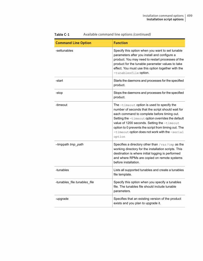
Table C-1 Available command line options (continued)
FunctionCommand Line Option
Specify this option when you want to set tunableparameters after you install and configure aproduct. You may need to restart processes of theproduct for the tunable parameter values to takeeffect. You must use this option together with the-tunablesfile option.
-settunables
Starts the daemons and processes for the specifiedproduct.
-start
Stops the daemons and processes for the specifiedproduct.
-stop
The -timeout option is used to specify thenumber of seconds that the script should wait foreach command to complete before timing out.Setting the -timeout option overrides the defaultvalue of 1200 seconds. Setting the -timeoutoption to 0 prevents the script from timing out. The-timeout option does not work with the -serialoption
-timeout
Specifies a directory other than /var/tmp as theworking directory for the installation scripts. Thisdestination is where initial logging is performedand where RPMs are copied on remote systemsbefore installation.
–tmppath tmp_path
Lists all supported tunables and create a tunablesfile template.
-tunables
Specify this option when you specify a tunablesfile. The tunables file should include tunableparameters.
-tunables_file tunables_file
Specifies that an existing version of the productexists and you plan to upgrade it.
-upgrade
499Installation command optionsInstallation script options
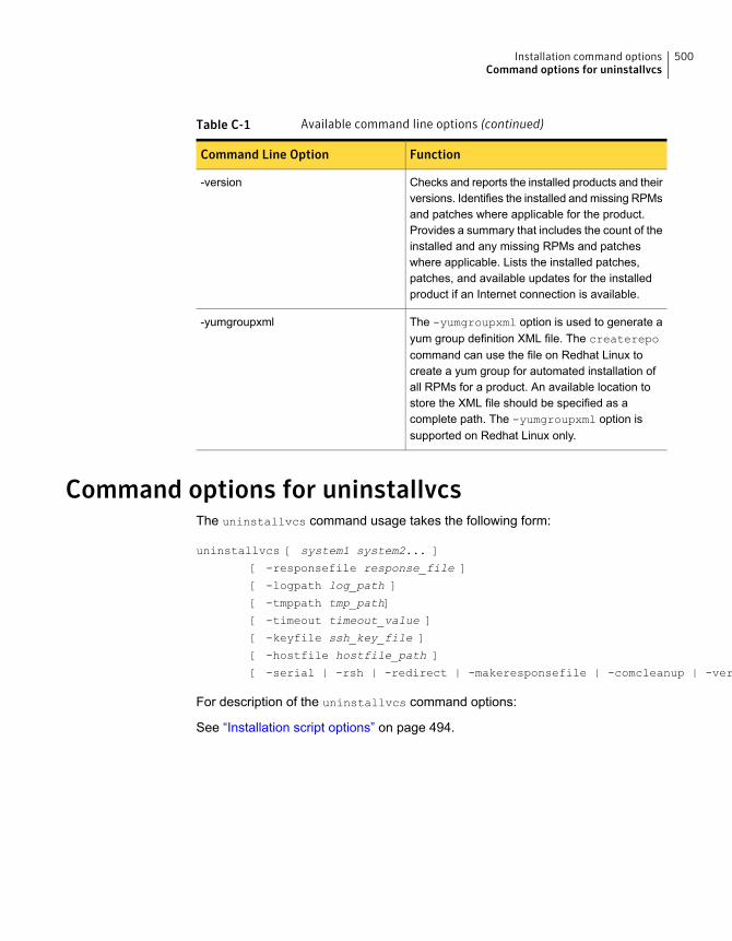
Table C-1 Available command line options (continued)
FunctionCommand Line Option
Checks and reports the installed products and theirversions. Identifies the installed and missing RPMsand patches where applicable for the product.Provides a summary that includes the count of theinstalled and any missing RPMs and patcheswhere applicable. Lists the installed patches,patches, and available updates for the installedproduct if an Internet connection is available.
-version
The -yumgroupxml option is used to generate ayum group definition XML file. The createrepocommand can use the file on Redhat Linux tocreate a yum group for automated installation ofall RPMs for a product. An available location tostore the XML file should be specified as acomplete path. The -yumgroupxml option issupported on Redhat Linux only.
-yumgroupxml
Command options for uninstallvcsThe uninstallvcs command usage takes the following form:
uninstallvcs [ system1 system2... ]
[ -responsefile response_file ]
[ -logpath log_path ]
[ -tmppath tmp_path]
[ -timeout timeout_value ]
[ -keyfile ssh_key_file ]
[ -hostfile hostfile_path ]
[ -serial | -rsh | -redirect | -makeresponsefile | -comcleanup | -version ]
For description of the uninstallvcs command options:
See “Installation script options” on page 494.
500Installation command optionsCommand options for uninstallvcs
Configuration files
This appendix includes the following topics:
■ About the LLT and GAB configuration files
■ About the AMF configuration files
■ About the VCS configuration files
■ About I/O fencing configuration files
■ Sample configuration files for CP server
About the LLT and GAB configuration filesLow Latency Transport (LLT) and Group Membership and Atomic Broadcast (GAB)are VCS communication services. LLT requires /etc/llthosts and /etc/llttab files.GAB requires /etc/gabtab file.
Table D-1 lists the LLT configuration files and the information that these files contain.
Table D-1 LLT configuration files
DescriptionFile
If you manually configured VCS, make sure you set the values of these environmentvariables to 1.
DAppendix
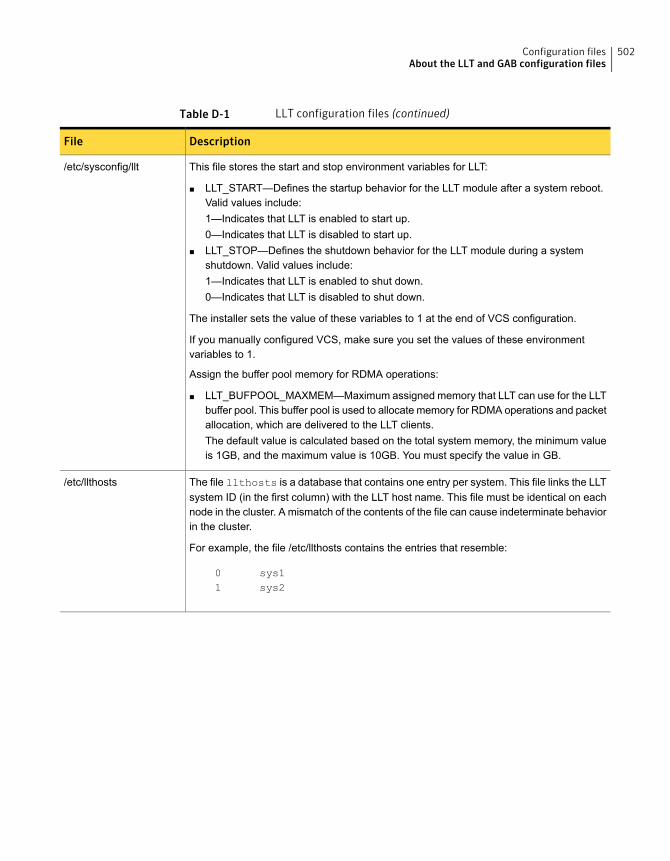
Table D-1 LLT configuration files (continued)
DescriptionFile
This file stores the start and stop environment variables for LLT:
■ LLT_START—Defines the startup behavior for the LLT module after a system reboot.Valid values include:1—Indicates that LLT is enabled to start up.0—Indicates that LLT is disabled to start up.
■ LLT_STOP—Defines the shutdown behavior for the LLT module during a systemshutdown. Valid values include:1—Indicates that LLT is enabled to shut down.0—Indicates that LLT is disabled to shut down.
The installer sets the value of these variables to 1 at the end of VCS configuration.
If you manually configured VCS, make sure you set the values of these environmentvariables to 1.
Assign the buffer pool memory for RDMA operations:
■ LLT_BUFPOOL_MAXMEM—Maximum assigned memory that LLT can use for the LLTbuffer pool. This buffer pool is used to allocate memory for RDMA operations and packetallocation, which are delivered to the LLT clients.The default value is calculated based on the total system memory, the minimum valueis 1GB, and the maximum value is 10GB. You must specify the value in GB.
/etc/sysconfig/llt
The file llthosts is a database that contains one entry per system. This file links the LLTsystem ID (in the first column) with the LLT host name. This file must be identical on eachnode in the cluster. A mismatch of the contents of the file can cause indeterminate behaviorin the cluster.
For example, the file /etc/llthosts contains the entries that resemble:
0 sys11 sys2
/etc/llthosts
502Configuration filesAbout the LLT and GAB configuration files
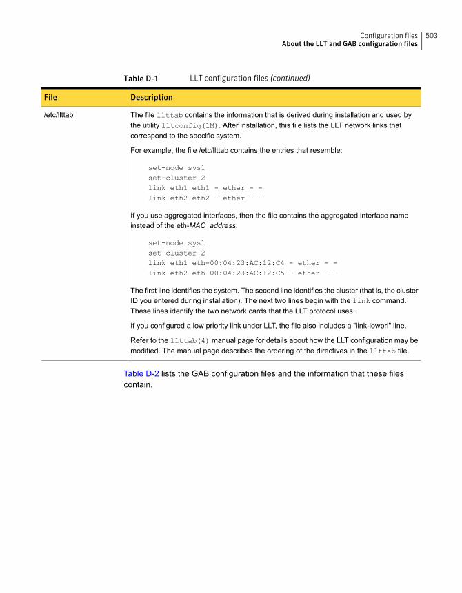
Table D-1 LLT configuration files (continued)
DescriptionFile
The file llttab contains the information that is derived during installation and used bythe utility lltconfig(1M). After installation, this file lists the LLT network links thatcorrespond to the specific system.
For example, the file /etc/llttab contains the entries that resemble:
set-node sys1set-cluster 2link eth1 eth1 - ether - -link eth2 eth2 - ether - -
If you use aggregated interfaces, then the file contains the aggregated interface nameinstead of the eth-MAC_address.
set-node sys1set-cluster 2link eth1 eth-00:04:23:AC:12:C4 - ether - -link eth2 eth-00:04:23:AC:12:C5 - ether - -
The first line identifies the system. The second line identifies the cluster (that is, the clusterID you entered during installation). The next two lines begin with the link command.These lines identify the two network cards that the LLT protocol uses.
If you configured a low priority link under LLT, the file also includes a "link-lowpri" line.
Refer to the llttab(4) manual page for details about how the LLT configuration may bemodified. The manual page describes the ordering of the directives in the llttab file.
/etc/llttab
Table D-2 lists the GAB configuration files and the information that these filescontain.
503Configuration filesAbout the LLT and GAB configuration files

Table D-2 GAB configuration files
DescriptionFile
This file stores the start and stop environment variables for GAB:
■ GAB_START—Defines the startup behavior for the GAB moduleafter a system reboot. Valid values include:1—Indicates that GAB is enabled to start up.0—Indicates that GAB is disabled to start up.
■ GAB_STOP—Defines the shutdown behavior for the GAB moduleduring a system shutdown. Valid values include:1—Indicates that GAB is enabled to shut down.0—Indicates that GAB is disabled to shut down.
The installer sets the value of these variables to 1 at the end of VCSconfiguration.
If you manually configured VCS, make sure you set the values of theseenvironment variables to 1.
/etc/sysconfig/gab
After you install VCS, the file /etc/gabtab contains a gabconfig(1)command that configures the GAB driver for use.
The file /etc/gabtab contains a line that resembles:
/sbin/gabconfig -c -nN
The -c option configures the driver for use. The -nN specifies that thecluster is not formed until at least N nodes are ready to form the cluster.Symantec recommends that you set N to be the total number of nodesin the cluster.
Note: Symantec does not recommend the use of the -c -x option for/sbin/gabconfig. Using -c -x can lead to a split-brain condition.Use the -c option for /sbin/gabconfig to avoid a split-braincondition.
Note:
/etc/gabtab
About the AMF configuration filesAsynchronous Monitoring Framework (AMF) kernel driver provides asynchronousevent notifications to the VCS agents that are enabled for intelligent resourcemonitoring.
Table D-3 lists the AMF configuration files.
504Configuration filesAbout the AMF configuration files
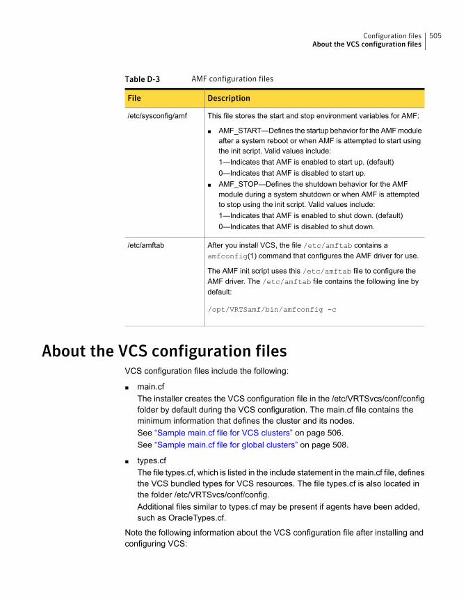
Table D-3 AMF configuration files
DescriptionFile
This file stores the start and stop environment variables for AMF:
■ AMF_START—Defines the startup behavior for the AMF moduleafter a system reboot or when AMF is attempted to start usingthe init script. Valid values include:1—Indicates that AMF is enabled to start up. (default)0—Indicates that AMF is disabled to start up.
■ AMF_STOP—Defines the shutdown behavior for the AMFmodule during a system shutdown or when AMF is attemptedto stop using the init script. Valid values include:1—Indicates that AMF is enabled to shut down. (default)0—Indicates that AMF is disabled to shut down.
/etc/sysconfig/amf
After you install VCS, the file /etc/amftab contains aamfconfig(1) command that configures the AMF driver for use.
The AMF init script uses this /etc/amftab file to configure theAMF driver. The /etc/amftab file contains the following line bydefault:
/opt/VRTSamf/bin/amfconfig -c
/etc/amftab
About the VCS configuration filesVCS configuration files include the following:
■ main.cfThe installer creates the VCS configuration file in the /etc/VRTSvcs/conf/configfolder by default during the VCS configuration. The main.cf file contains theminimum information that defines the cluster and its nodes.See “Sample main.cf file for VCS clusters” on page 506.See “Sample main.cf file for global clusters” on page 508.
■ types.cfThe file types.cf, which is listed in the include statement in the main.cf file, definesthe VCS bundled types for VCS resources. The file types.cf is also located inthe folder /etc/VRTSvcs/conf/config.Additional files similar to types.cf may be present if agents have been added,such as OracleTypes.cf.
Note the following information about the VCS configuration file after installing andconfiguring VCS:
505Configuration filesAbout the VCS configuration files

■ The cluster definition includes the cluster information that you provided duringthe configuration. This definition includes the cluster name, cluster address, andthe names of users and administrators of the cluster.Notice that the cluster has an attribute UserNames. The installvcs creates auser "admin" whose password is encrypted; the word "password" is the defaultpassword.
■ If you set up the optional I/O fencing feature for VCS, then the UseFence =SCSI3 attribute is present.
■ If you configured the cluster in secure mode, the main.cf includes "SecureClus= 1" cluster attribute.
■ The installvcs creates the ClusterService service group if you configured thevirtual IP, SMTP, SNMP, or global cluster options.
The service group also has the following characteristics:
■ The group includes the IP and NIC resources.
■ The service group also includes the notifier resource configuration, which isbased on your input to installvcs prompts about notification.
■ The installvcs also creates a resource dependency tree.
■ If you set up global clusters, the ClusterService service group contains anApplication resource, wac (wide-area connector). This resource’s attributescontain definitions for controlling the cluster in a global cluster environment.Refer to the Symantec Cluster Server Administrator's Guide for informationabout managing VCS global clusters.
Refer to the Symantec Cluster Server Administrator's Guide to review theconfiguration concepts, and descriptions of main.cf and types.cf files for Linuxsystems.
Sample main.cf file for VCS clustersThe following sample main.cf file is for a cluster in secure mode.
include "types.cf"
include "OracleTypes.cf"
include "OracleASMTypes.cf"
include "Db2udbTypes.cf"
include "SybaseTypes.cf"
cluster vcs_cluster2 (
UserNames = { admin = cDRpdxPmHpzS, smith = dKLhKJkHLh }
506Configuration filesAbout the VCS configuration files
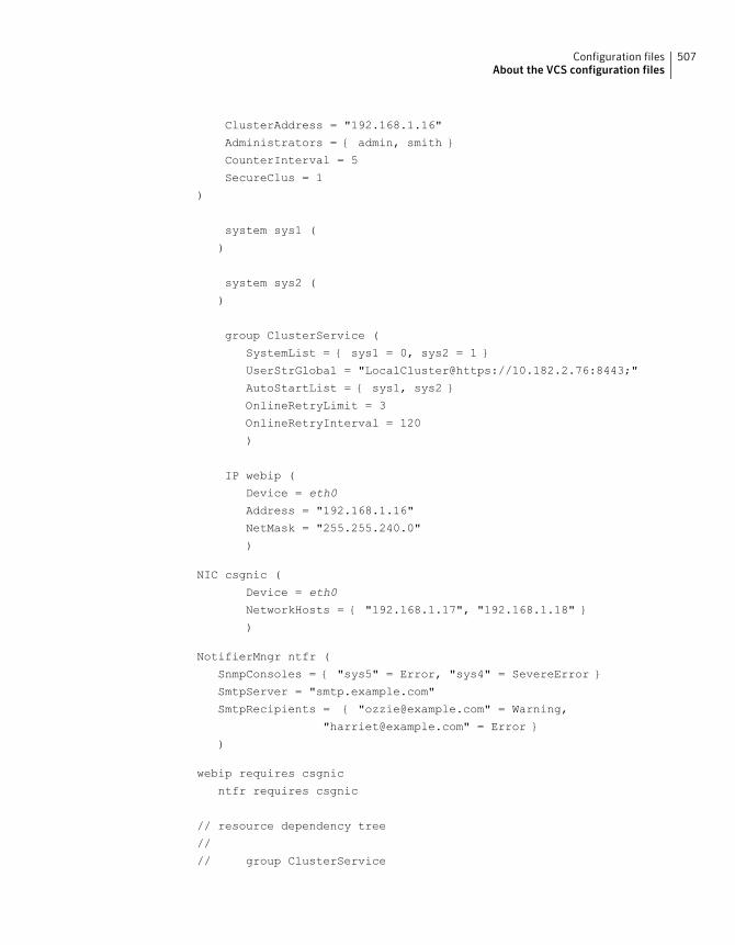
ClusterAddress = "192.168.1.16"
Administrators = { admin, smith }
CounterInterval = 5
SecureClus = 1
)
system sys1 (
)
system sys2 (
)
group ClusterService (
SystemList = { sys1 = 0, sys2 = 1 }
UserStrGlobal = "LocalCluster@https://10.182.2.76:8443;"
AutoStartList = { sys1, sys2 }
OnlineRetryLimit = 3
OnlineRetryInterval = 120
)
IP webip (
Device = eth0
Address = "192.168.1.16"
NetMask = "255.255.240.0"
)
NIC csgnic (
Device = eth0
NetworkHosts = { "192.168.1.17", "192.168.1.18" }
)
NotifierMngr ntfr (
SnmpConsoles = { "sys5" = Error, "sys4" = SevereError }
SmtpServer = "smtp.example.com"
SmtpRecipients = { "[email protected]" = Warning,
"[email protected]" = Error }
)
webip requires csgnic
ntfr requires csgnic
// resource dependency tree
//
// group ClusterService
507Configuration filesAbout the VCS configuration files
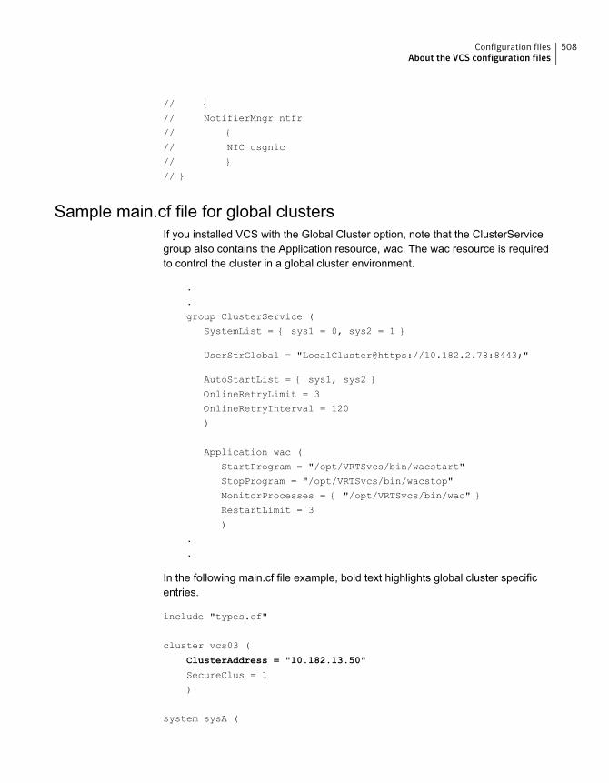
// {
// NotifierMngr ntfr
// {
// NIC csgnic
// }
// }
Sample main.cf file for global clustersIf you installed VCS with the Global Cluster option, note that the ClusterServicegroup also contains the Application resource, wac. The wac resource is requiredto control the cluster in a global cluster environment.
.
.
group ClusterService (
SystemList = { sys1 = 0, sys2 = 1 }
UserStrGlobal = "LocalCluster@https://10.182.2.78:8443;"
AutoStartList = { sys1, sys2 }
OnlineRetryLimit = 3
OnlineRetryInterval = 120
)
Application wac (
StartProgram = "/opt/VRTSvcs/bin/wacstart"
StopProgram = "/opt/VRTSvcs/bin/wacstop"
MonitorProcesses = { "/opt/VRTSvcs/bin/wac" }
RestartLimit = 3
)
.
.
In the following main.cf file example, bold text highlights global cluster specificentries.
include "types.cf"
cluster vcs03 (
ClusterAddress = "10.182.13.50"
SecureClus = 1
)
system sysA (
508Configuration filesAbout the VCS configuration files
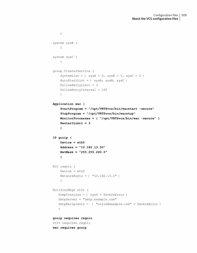
)
system sysB (
)
system sysC (
)
group ClusterService (
SystemList = { sysA = 0, sysB = 1, sysC = 2 }
AutoStartList = { sysA, sysB, sysC }
OnlineRetryLimit = 3
OnlineRetryInterval = 120
)
Application wac (
StartProgram = "/opt/VRTSvcs/bin/wacstart -secure"
StopProgram = "/opt/VRTSvcs/bin/wacstop"
MonitorProcesses = { "/opt/VRTSvcs/bin/wac -secure" }
RestartLimit = 3
)
IP gcoip (
Device = eth0
Address = "10.182.13.50"
NetMask = "255.255.240.0"
)
NIC csgnic (
Device = eth0
NetworkHosts = { "10.182.13.1" }
)
NotifierMngr ntfr (
SnmpConsoles = { sys4 = SevereError }
SmtpServer = "smtp.example.com"
SmtpRecipients = { "[email protected]" = SevereError }
)
gcoip requires csgnic
ntfr requires csgnic
wac requires gcoip
509Configuration filesAbout the VCS configuration files
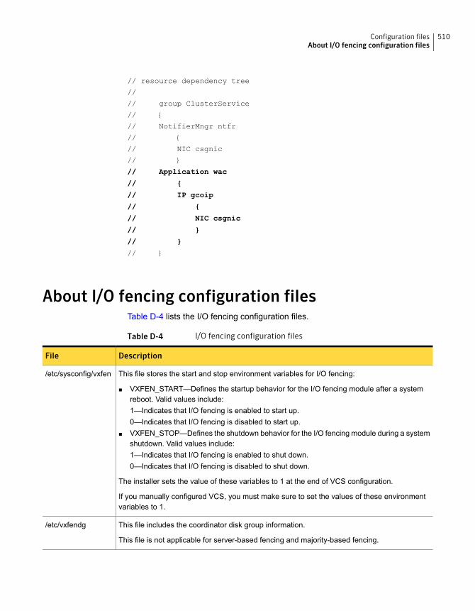
// resource dependency tree
//
// group ClusterService
// {
// NotifierMngr ntfr
// {
// NIC csgnic
// }
// Application wac
// {
// IP gcoip
// {
// NIC csgnic
// }
// }
// }
About I/O fencing configuration filesTable D-4 lists the I/O fencing configuration files.
Table D-4 I/O fencing configuration files
DescriptionFile
This file stores the start and stop environment variables for I/O fencing:
■ VXFEN_START—Defines the startup behavior for the I/O fencing module after a systemreboot. Valid values include:1—Indicates that I/O fencing is enabled to start up.0—Indicates that I/O fencing is disabled to start up.
■ VXFEN_STOP—Defines the shutdown behavior for the I/O fencing module during a systemshutdown. Valid values include:1—Indicates that I/O fencing is enabled to shut down.0—Indicates that I/O fencing is disabled to shut down.
The installer sets the value of these variables to 1 at the end of VCS configuration.
If you manually configured VCS, you must make sure to set the values of these environmentvariables to 1.
/etc/sysconfig/vxfen
This file includes the coordinator disk group information.
This file is not applicable for server-based fencing and majority-based fencing.
/etc/vxfendg
510Configuration filesAbout I/O fencing configuration files
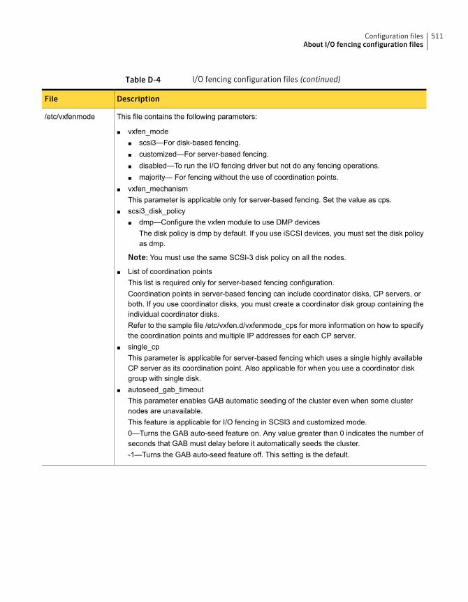
Table D-4 I/O fencing configuration files (continued)
DescriptionFile
This file contains the following parameters:
■ vxfen_mode■ scsi3—For disk-based fencing.■ customized—For server-based fencing.■ disabled—To run the I/O fencing driver but not do any fencing operations.■ majority— For fencing without the use of coordination points.
■ vxfen_mechanismThis parameter is applicable only for server-based fencing. Set the value as cps.
■ scsi3_disk_policy■ dmp—Configure the vxfen module to use DMP devices
The disk policy is dmp by default. If you use iSCSI devices, you must set the disk policyas dmp.
Note: You must use the same SCSI-3 disk policy on all the nodes.
■ List of coordination pointsThis list is required only for server-based fencing configuration.Coordination points in server-based fencing can include coordinator disks, CP servers, orboth. If you use coordinator disks, you must create a coordinator disk group containing theindividual coordinator disks.Refer to the sample file /etc/vxfen.d/vxfenmode_cps for more information on how to specifythe coordination points and multiple IP addresses for each CP server.
■ single_cpThis parameter is applicable for server-based fencing which uses a single highly availableCP server as its coordination point. Also applicable for when you use a coordinator diskgroup with single disk.
■ autoseed_gab_timeoutThis parameter enables GAB automatic seeding of the cluster even when some clusternodes are unavailable.This feature is applicable for I/O fencing in SCSI3 and customized mode.0—Turns the GAB auto-seed feature on. Any value greater than 0 indicates the number ofseconds that GAB must delay before it automatically seeds the cluster.-1—Turns the GAB auto-seed feature off. This setting is the default.
/etc/vxfenmode
511Configuration filesAbout I/O fencing configuration files
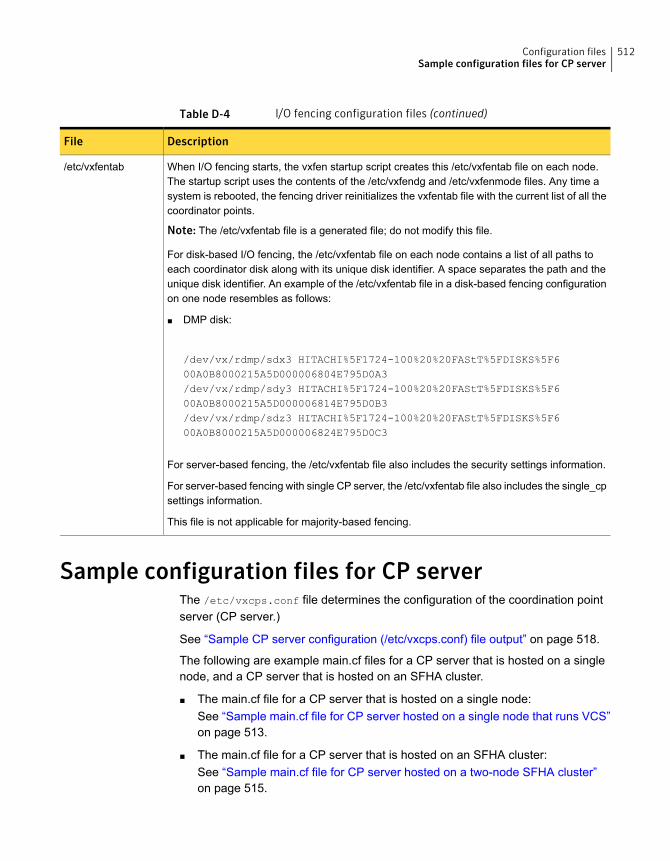
Table D-4 I/O fencing configuration files (continued)
DescriptionFile
When I/O fencing starts, the vxfen startup script creates this /etc/vxfentab file on each node.The startup script uses the contents of the /etc/vxfendg and /etc/vxfenmode files. Any time asystem is rebooted, the fencing driver reinitializes the vxfentab file with the current list of all thecoordinator points.
Note: The /etc/vxfentab file is a generated file; do not modify this file.
For disk-based I/O fencing, the /etc/vxfentab file on each node contains a list of all paths toeach coordinator disk along with its unique disk identifier. A space separates the path and theunique disk identifier. An example of the /etc/vxfentab file in a disk-based fencing configurationon one node resembles as follows:
■ DMP disk:
/dev/vx/rdmp/sdx3 HITACHI%5F1724-100%20%20FAStT%5FDISKS%5F600A0B8000215A5D000006804E795D0A3/dev/vx/rdmp/sdy3 HITACHI%5F1724-100%20%20FAStT%5FDISKS%5F600A0B8000215A5D000006814E795D0B3/dev/vx/rdmp/sdz3 HITACHI%5F1724-100%20%20FAStT%5FDISKS%5F600A0B8000215A5D000006824E795D0C3
For server-based fencing, the /etc/vxfentab file also includes the security settings information.
For server-based fencing with single CP server, the /etc/vxfentab file also includes the single_cpsettings information.
This file is not applicable for majority-based fencing.
/etc/vxfentab
Sample configuration files for CP serverThe /etc/vxcps.conf file determines the configuration of the coordination pointserver (CP server.)
See “Sample CP server configuration (/etc/vxcps.conf) file output” on page 518.
The following are example main.cf files for a CP server that is hosted on a singlenode, and a CP server that is hosted on an SFHA cluster.
■ The main.cf file for a CP server that is hosted on a single node:See “Sample main.cf file for CP server hosted on a single node that runs VCS”on page 513.
■ The main.cf file for a CP server that is hosted on an SFHA cluster:See “Sample main.cf file for CP server hosted on a two-node SFHA cluster”on page 515.
512Configuration filesSample configuration files for CP server
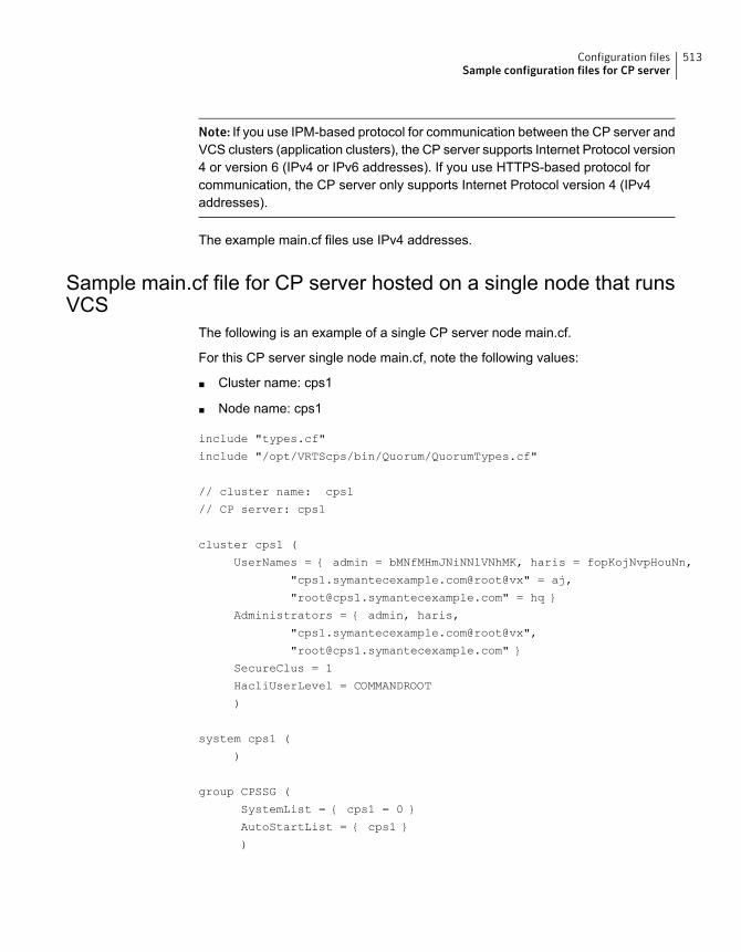
Note: If you use IPM-based protocol for communication between the CP server andVCS clusters (application clusters), the CP server supports Internet Protocol version4 or version 6 (IPv4 or IPv6 addresses). If you use HTTPS-based protocol forcommunication, the CP server only supports Internet Protocol version 4 (IPv4addresses).
The example main.cf files use IPv4 addresses.
Sample main.cf file for CP server hosted on a single node that runsVCS
The following is an example of a single CP server node main.cf.
For this CP server single node main.cf, note the following values:
■ Cluster name: cps1
■ Node name: cps1
include "types.cf"
include "/opt/VRTScps/bin/Quorum/QuorumTypes.cf"
// cluster name: cps1
// CP server: cps1
cluster cps1 (
UserNames = { admin = bMNfMHmJNiNNlVNhMK, haris = fopKojNvpHouNn,
"cps1.symantecexample.com@root@vx" = aj,
"[email protected]" = hq }
Administrators = { admin, haris,
"cps1.symantecexample.com@root@vx",
SecureClus = 1
HacliUserLevel = COMMANDROOT
)
system cps1 (
)
group CPSSG (
SystemList = { cps1 = 0 }
AutoStartList = { cps1 }
)
513Configuration filesSample configuration files for CP server
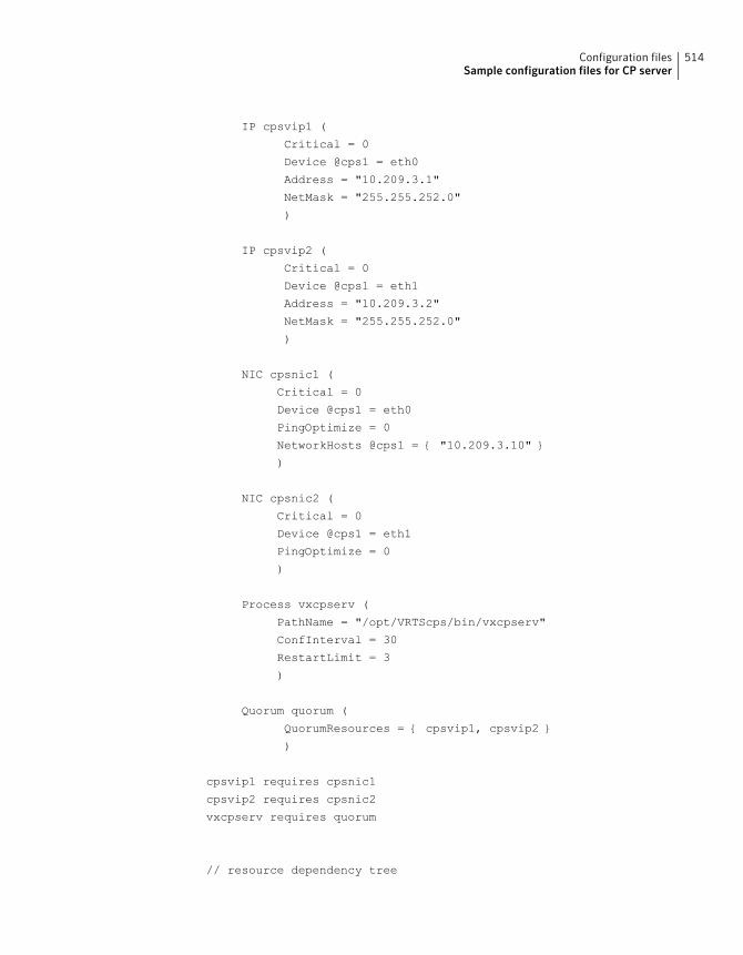
IP cpsvip1 (
Critical = 0
Device @cps1 = eth0
Address = "10.209.3.1"
NetMask = "255.255.252.0"
)
IP cpsvip2 (
Critical = 0
Device @cps1 = eth1
Address = "10.209.3.2"
NetMask = "255.255.252.0"
)
NIC cpsnic1 (
Critical = 0
Device @cps1 = eth0
PingOptimize = 0
NetworkHosts @cps1 = { "10.209.3.10" }
)
NIC cpsnic2 (
Critical = 0
Device @cps1 = eth1
PingOptimize = 0
)
Process vxcpserv (
PathName = "/opt/VRTScps/bin/vxcpserv"
ConfInterval = 30
RestartLimit = 3
)
Quorum quorum (
QuorumResources = { cpsvip1, cpsvip2 }
)
cpsvip1 requires cpsnic1
cpsvip2 requires cpsnic2
vxcpserv requires quorum
// resource dependency tree
514Configuration filesSample configuration files for CP server
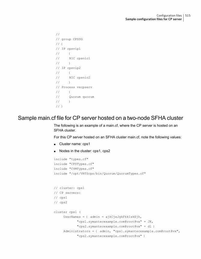
//
// group CPSSG
// {
// IP cpsvip1
// {
// NIC cpsnic1
// }
// IP cpsvip2
// {
// NIC cpsnic2
// }
// Process vxcpserv
// {
// Quorum quorum
// }
// }
Sample main.cf file for CP server hosted on a two-node SFHA clusterThe following is an example of a main.cf, where the CP server is hosted on anSFHA cluster.
For this CP server hosted on an SFHA cluster main.cf, note the following values:
■ Cluster name: cps1
■ Nodes in the cluster: cps1, cps2
include "types.cf"
include "CFSTypes.cf"
include "CVMTypes.cf"
include "/opt/VRTScps/bin/Quorum/QuorumTypes.cf"
// cluster: cps1
// CP servers:
// cps1
// cps2
cluster cps1 (
UserNames = { admin = ajkCjeJgkFkkIskEjh,
"cps1.symantecexample.com@root@vx" = JK,
"cps2.symantecexample.com@root@vx" = dl }
Administrators = { admin, "cps1.symantecexample.com@root@vx",
"cps2.symantecexample.com@root@vx" }
515Configuration filesSample configuration files for CP server
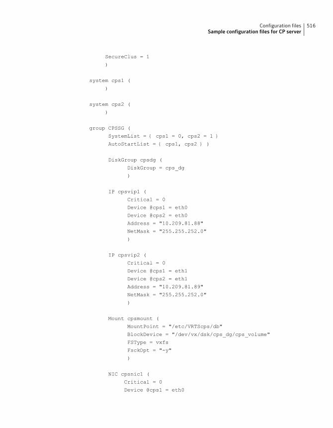
SecureClus = 1
)
system cps1 (
)
system cps2 (
)
group CPSSG (
SystemList = { cps1 = 0, cps2 = 1 }
AutoStartList = { cps1, cps2 } )
DiskGroup cpsdg (
DiskGroup = cps_dg
)
IP cpsvip1 (
Critical = 0
Device @cps1 = eth0
Device @cps2 = eth0
Address = "10.209.81.88"
NetMask = "255.255.252.0"
)
IP cpsvip2 (
Critical = 0
Device @cps1 = eth1
Device @cps2 = eth1
Address = "10.209.81.89"
NetMask = "255.255.252.0"
)
Mount cpsmount (
MountPoint = "/etc/VRTScps/db"
BlockDevice = "/dev/vx/dsk/cps_dg/cps_volume"
FSType = vxfs
FsckOpt = "-y"
)
NIC cpsnic1 (
Critical = 0
Device @cps1 = eth0
516Configuration filesSample configuration files for CP server
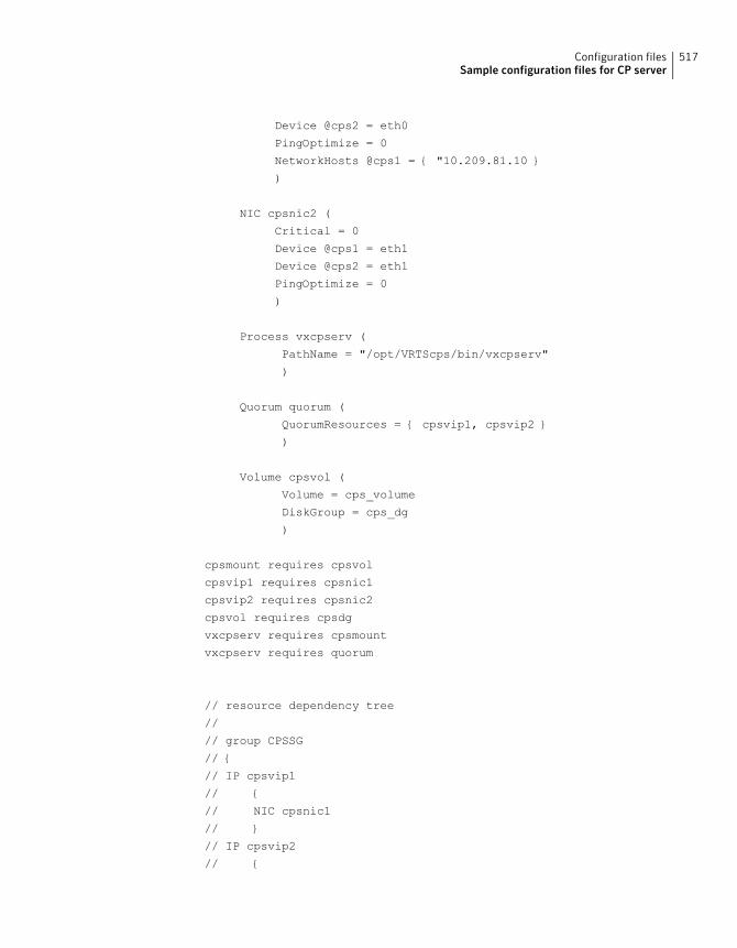
Device @cps2 = eth0
PingOptimize = 0
NetworkHosts @cps1 = { "10.209.81.10 }
)
NIC cpsnic2 (
Critical = 0
Device @cps1 = eth1
Device @cps2 = eth1
PingOptimize = 0
)
Process vxcpserv (
PathName = "/opt/VRTScps/bin/vxcpserv"
)
Quorum quorum (
QuorumResources = { cpsvip1, cpsvip2 }
)
Volume cpsvol (
Volume = cps_volume
DiskGroup = cps_dg
)
cpsmount requires cpsvol
cpsvip1 requires cpsnic1
cpsvip2 requires cpsnic2
cpsvol requires cpsdg
vxcpserv requires cpsmount
vxcpserv requires quorum
// resource dependency tree
//
// group CPSSG
// {
// IP cpsvip1
// {
// NIC cpsnic1
// }
// IP cpsvip2
// {
517Configuration filesSample configuration files for CP server

// NIC cpsnic2
// }
// Process vxcpserv
// {
// Quorum quorum
// Mount cpsmount
// {
// Volume cpsvol
// {
// DiskGroup cpsdg
// }
// }
// }
// }
Sample CP server configuration (/etc/vxcps.conf) file outputThe following is an example of a coordination point server (CP server) configurationfile /etc/vxcps.conf output.
## The vxcps.conf file determines the
## configuration for Veritas CP Server.
cps_name=cps1
vip=[10.209.81.88]
vip=[10.209.81.89]:56789
vip_https=[10.209.81.88]:55443
vip_https=[10.209.81.89]
port=14250
port_https=443
security=1
db=/etc/VRTScps/db
ssl_conf_file=/etc/vxcps_ssl.properties
518Configuration filesSample configuration files for CP server
Installing VCS on a singlenode
This appendix includes the following topics:
■ About installing VCS on a single node
■ Creating a single-node cluster using the installer program
■ Creating a single-node cluster manually
■ Setting the path variable for a manual single node installation
■ Installing VCS software manually on a single node
■ Modifying the startup files
■ Configuring VCS
■ Verifying single-node operation
About installing VCS on a single nodeYou can install VCS 6.2 on a single node. You can subsequently add another nodeto the single-node cluster to form a multinode cluster. You can also prepare a singlenode cluster for addition into a multi-node cluster. Single node clusters can be usedfor testing as well.
You can install VCS onto a single node using the installer program or you can addit manually.
See “Creating a single-node cluster using the installer program” on page 520.
See “Creating a single-node cluster manually” on page 521.
EAppendix
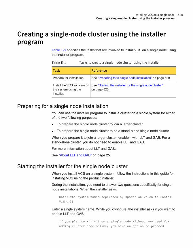
Creating a single-node cluster using the installerprogram
Table E-1 specifies the tasks that are involved to install VCS on a single node usingthe installer program.
Table E-1 Tasks to create a single-node cluster using the installer
ReferenceTask
See “Preparing for a single node installation” on page 520.Prepare for installation.
See “Starting the installer for the single node cluster”on page 520.
Install the VCS software onthe system using theinstaller.
Preparing for a single node installationYou can use the installer program to install a cluster on a single system for eitherof the two following purposes:
■ To prepare the single node cluster to join a larger cluster
■ To prepare the single node cluster to be a stand-alone single node cluster
When you prepare it to join a larger cluster, enable it with LLT and GAB. For astand-alone cluster, you do not need to enable LLT and GAB.
For more information about LLT and GAB:
See “About LLT and GAB” on page 25.
Starting the installer for the single node clusterWhen you install VCS on a single system, follow the instructions in this guide forinstalling VCS using the product installer.
During the installation, you need to answer two questions specifically for singlenode installations. When the installer asks:
Enter the system names separated by spaces on which to install
VCS[q,?]
Enter a single system name. While you configure, the installer asks if you want toenable LLT and GAB:
If you plan to run VCS on a single node without any need for
adding cluster node online, you have an option to proceed
520Installing VCS on a single nodeCreating a single-node cluster using the installer program
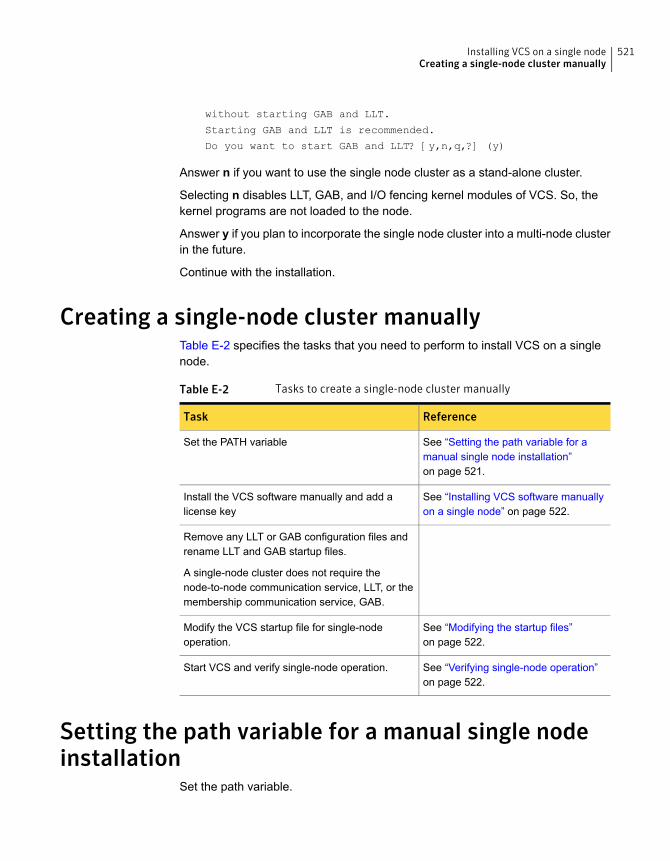
without starting GAB and LLT.
Starting GAB and LLT is recommended.
Do you want to start GAB and LLT? [y,n,q,?] (y)
Answer n if you want to use the single node cluster as a stand-alone cluster.
Selecting n disables LLT, GAB, and I/O fencing kernel modules of VCS. So, thekernel programs are not loaded to the node.
Answer y if you plan to incorporate the single node cluster into a multi-node clusterin the future.
Continue with the installation.
Creating a single-node cluster manuallyTable E-2 specifies the tasks that you need to perform to install VCS on a singlenode.
Table E-2 Tasks to create a single-node cluster manually
ReferenceTask
See “Setting the path variable for amanual single node installation”on page 521.
Set the PATH variable
See “Installing VCS software manuallyon a single node” on page 522.
Install the VCS software manually and add alicense key
Remove any LLT or GAB configuration files andrename LLT and GAB startup files.
A single-node cluster does not require thenode-to-node communication service, LLT, or themembership communication service, GAB.
See “Modifying the startup files”on page 522.
Modify the VCS startup file for single-nodeoperation.
See “Verifying single-node operation”on page 522.
Start VCS and verify single-node operation.
Setting the path variable for a manual single nodeinstallation
Set the path variable.
521Installing VCS on a single nodeCreating a single-node cluster manually
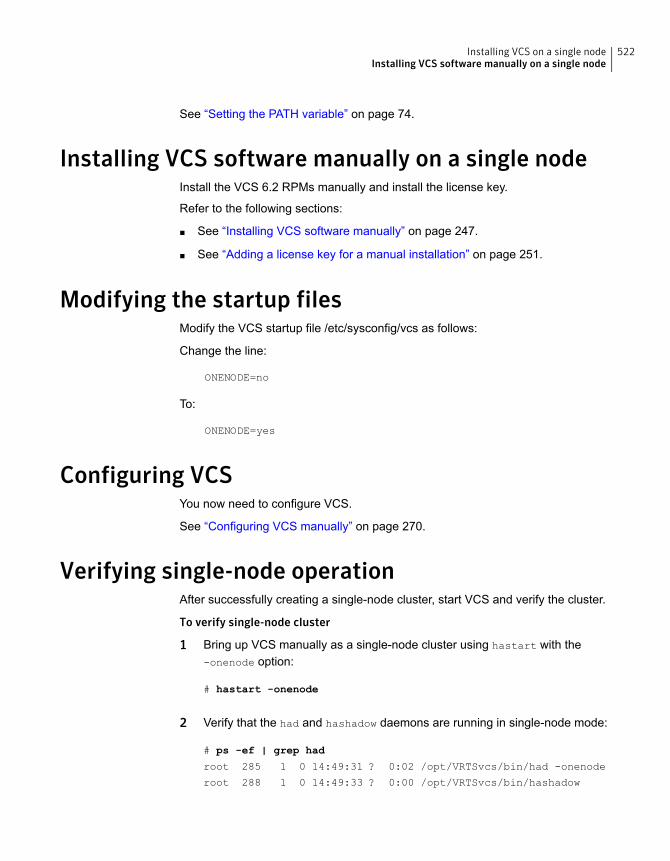
See “Setting the PATH variable” on page 74.
Installing VCS software manually on a single nodeInstall the VCS 6.2 RPMs manually and install the license key.
Refer to the following sections:
■ See “Installing VCS software manually” on page 247.
■ See “Adding a license key for a manual installation” on page 251.
Modifying the startup filesModify the VCS startup file /etc/sysconfig/vcs as follows:
Change the line:
ONENODE=no
To:
ONENODE=yes
Configuring VCSYou now need to configure VCS.
See “Configuring VCS manually” on page 270.
Verifying single-node operationAfter successfully creating a single-node cluster, start VCS and verify the cluster.
To verify single-node cluster
1 Bring up VCS manually as a single-node cluster using hastart with the-onenode option:
# hastart -onenode
2 Verify that the had and hashadow daemons are running in single-node mode:
# ps -ef | grep had
root 285 1 0 14:49:31 ? 0:02 /opt/VRTSvcs/bin/had -onenode
root 288 1 0 14:49:33 ? 0:00 /opt/VRTSvcs/bin/hashadow
522Installing VCS on a single nodeInstalling VCS software manually on a single node
Configuring LLT over UDP
This appendix includes the following topics:
■ Using the UDP layer for LLT
■ Manually configuring LLT over UDP using IPv4
■ Manually configuring LLT over UDP using IPv6
■ LLT over UDP sample /etc/llttab
Using the UDP layer for LLTVCS provides the option of using LLT over the UDP (User Datagram Protocol) layerfor clusters using wide-area networks and routers. UDP makes LLT packets routableand thus able to span longer distances more economically.
When to use LLT over UDPUse LLT over UDP in the following situations:
■ LLT must be used over WANs
■ When hardware, such as blade servers, do not support LLT over Ethernet
LLT over UDP is slower than LLT over Ethernet. Use LLT over UDP only when thehardware configuration makes it necessary.
Manually configuring LLT over UDP using IPv4The following checklist is to configure LLT over UDP:
■ Make sure that the LLT private links are on separate subnets. Set the broadcastaddress in /etc/llttab explicitly depending on the subnet for each link.
FAppendix

See “Broadcast address in the /etc/llttab file” on page 524.
■ Make sure that each NIC has an IP address that is configured before configuringLLT.
■ Make sure the IP addresses in the /etc/llttab files are consistent with the IPaddresses of the network interfaces.
■ Make sure that each link has a unique not well-known UDP port.See “Selecting UDP ports” on page 526.
■ Set the broadcast address correctly for direct-attached (non-routed) links.See “Sample configuration: direct-attached links” on page 527.
■ For the links that cross an IP router, disable broadcast features and specify theIP address of each link manually in the /etc/llttab file.See “Sample configuration: links crossing IP routers” on page 529.
Broadcast address in the /etc/llttab fileThe broadcast address is set explicitly for each link in the following example.
■ Display the content of the /etc/llttab file on the first node sys1:
sys1 # cat /etc/llttab
set-node sys1
set-cluster 1
link link1 udp - udp 50000 - 192.168.9.1 192.168.9.255
link link2 udp - udp 50001 - 192.168.10.1 192.168.10.255
Verify the subnet mask using the ifconfig command to ensure that the two linksare on separate subnets.
■ Display the content of the /etc/llttab file on the second node sys2:
sys2 # cat /etc/llttab
set-node sys2
set-cluster 1
link link1 udp - udp 50000 - 192.168.9.2 192.168.9.255
link link2 udp - udp 50001 - 192.168.10.2 192.168.10.255
Verify the subnet mask using the ifconfig command to ensure that the two linksare on separate subnets.
524Configuring LLT over UDPManually configuring LLT over UDP using IPv4
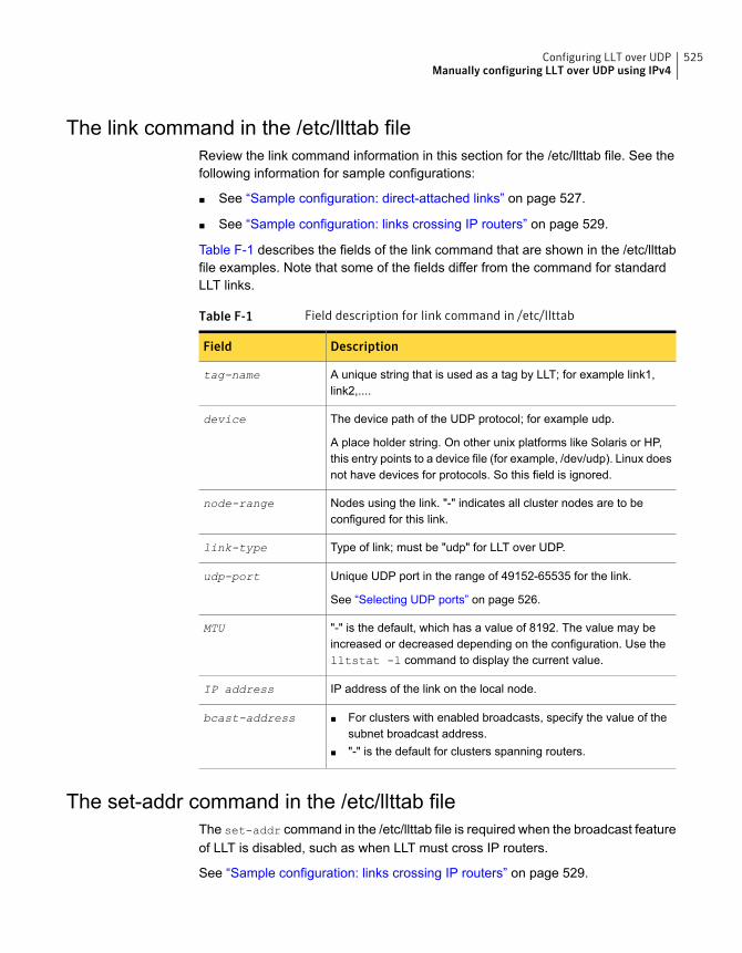
The link command in the /etc/llttab fileReview the link command information in this section for the /etc/llttab file. See thefollowing information for sample configurations:
■ See “Sample configuration: direct-attached links” on page 527.
■ See “Sample configuration: links crossing IP routers” on page 529.
Table F-1 describes the fields of the link command that are shown in the /etc/llttabfile examples. Note that some of the fields differ from the command for standardLLT links.
Table F-1 Field description for link command in /etc/llttab
DescriptionField
A unique string that is used as a tag by LLT; for example link1,link2,....
tag-name
The device path of the UDP protocol; for example udp.
A place holder string. On other unix platforms like Solaris or HP,this entry points to a device file (for example, /dev/udp). Linux doesnot have devices for protocols. So this field is ignored.
device
Nodes using the link. "-" indicates all cluster nodes are to beconfigured for this link.
node-range
Type of link; must be "udp" for LLT over UDP.link-type
Unique UDP port in the range of 49152-65535 for the link.
See “Selecting UDP ports” on page 526.
udp-port
"-" is the default, which has a value of 8192. The value may beincreased or decreased depending on the configuration. Use thelltstat -l command to display the current value.
MTU
IP address of the link on the local node.IP address
■ For clusters with enabled broadcasts, specify the value of thesubnet broadcast address.
■ "-" is the default for clusters spanning routers.
bcast-address
The set-addr command in the /etc/llttab fileThe set-addr command in the /etc/llttab file is required when the broadcast featureof LLT is disabled, such as when LLT must cross IP routers.
See “Sample configuration: links crossing IP routers” on page 529.
525Configuring LLT over UDPManually configuring LLT over UDP using IPv4
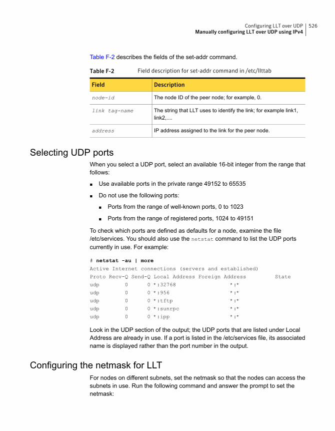
Table F-2 describes the fields of the set-addr command.
Table F-2 Field description for set-addr command in /etc/llttab
DescriptionField
The node ID of the peer node; for example, 0.node-id
The string that LLT uses to identify the link; for example link1,link2,....
link tag-name
IP address assigned to the link for the peer node.address
Selecting UDP portsWhen you select a UDP port, select an available 16-bit integer from the range thatfollows:
■ Use available ports in the private range 49152 to 65535
■ Do not use the following ports:
■ Ports from the range of well-known ports, 0 to 1023
■ Ports from the range of registered ports, 1024 to 49151
To check which ports are defined as defaults for a node, examine the file/etc/services. You should also use the netstat command to list the UDP portscurrently in use. For example:
# netstat -au | more
Active Internet connections (servers and established)
Proto Recv-Q Send-Q Local Address Foreign Address State
udp 0 0 *:32768 *:*
udp 0 0 *:956 *:*
udp 0 0 *:tftp *:*
udp 0 0 *:sunrpc *:*
udp 0 0 *:ipp *:*
Look in the UDP section of the output; the UDP ports that are listed under LocalAddress are already in use. If a port is listed in the /etc/services file, its associatedname is displayed rather than the port number in the output.
Configuring the netmask for LLTFor nodes on different subnets, set the netmask so that the nodes can access thesubnets in use. Run the following command and answer the prompt to set thenetmask:
526Configuring LLT over UDPManually configuring LLT over UDP using IPv4
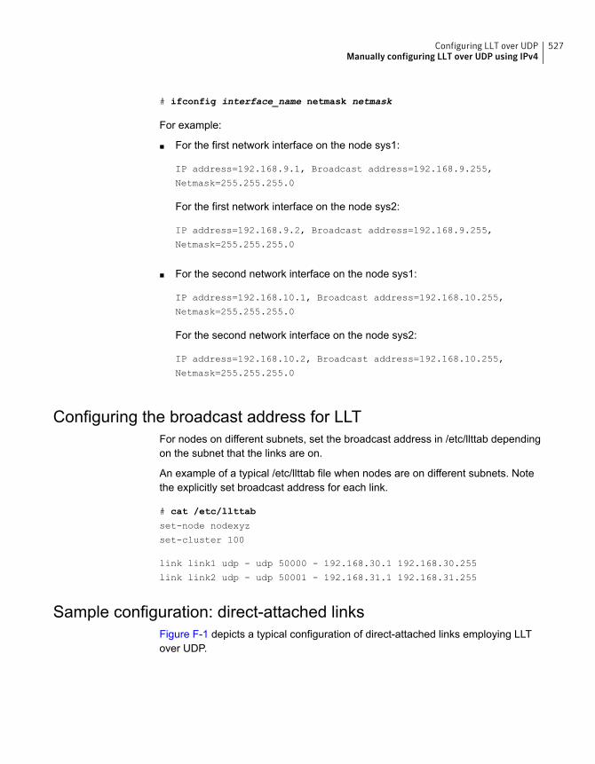
# ifconfig interface_name netmask netmask
For example:
■ For the first network interface on the node sys1:
IP address=192.168.9.1, Broadcast address=192.168.9.255,
Netmask=255.255.255.0
For the first network interface on the node sys2:
IP address=192.168.9.2, Broadcast address=192.168.9.255,
Netmask=255.255.255.0
■ For the second network interface on the node sys1:
IP address=192.168.10.1, Broadcast address=192.168.10.255,
Netmask=255.255.255.0
For the second network interface on the node sys2:
IP address=192.168.10.2, Broadcast address=192.168.10.255,
Netmask=255.255.255.0
Configuring the broadcast address for LLTFor nodes on different subnets, set the broadcast address in /etc/llttab dependingon the subnet that the links are on.
An example of a typical /etc/llttab file when nodes are on different subnets. Notethe explicitly set broadcast address for each link.
# cat /etc/llttab
set-node nodexyz
set-cluster 100
link link1 udp - udp 50000 - 192.168.30.1 192.168.30.255
link link2 udp - udp 50001 - 192.168.31.1 192.168.31.255
Sample configuration: direct-attached linksFigure F-1 depicts a typical configuration of direct-attached links employing LLTover UDP.
527Configuring LLT over UDPManually configuring LLT over UDP using IPv4
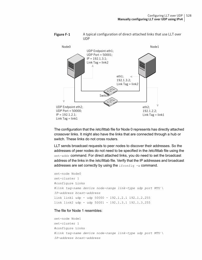
Figure F-1 A typical configuration of direct-attached links that use LLT overUDP
UDP Endpoint eth1;UDP Port = 50001;IP = 192.1.3.1;Link Tag = link2
UDP Endpoint eth2;UDP Port = 50000;IP = 192.1.2.1;Link Tag = link1
eth1;192.1.3.2;Link Tag = link2
eth2;192.1.2.2;Link Tag = link1
Switch
Node0 Node1
The configuration that the /etc/llttab file for Node 0 represents has directly attachedcrossover links. It might also have the links that are connected through a hub orswitch. These links do not cross routers.
LLT sends broadcast requests to peer nodes to discover their addresses. So theaddresses of peer nodes do not need to be specified in the /etc/llttab file using theset-addr command. For direct attached links, you do need to set the broadcastaddress of the links in the /etc/llttab file. Verify that the IP addresses and broadcastaddresses are set correctly by using the ifconfig -a command.
set-node Node0
set-cluster 1
#configure Links
#link tag-name device node-range link-type udp port MTU \
IP-address bcast-address
link link1 udp - udp 50000 - 192.1.2.1 192.1.2.255
link link2 udp - udp 50001 - 192.1.3.1 192.1.3.255
The file for Node 1 resembles:
set-node Node1
set-cluster 1
#configure Links
#link tag-name device node-range link-type udp port MTU \
IP-address bcast-address
528Configuring LLT over UDPManually configuring LLT over UDP using IPv4
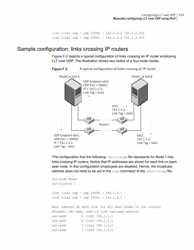
link link1 udp - udp 50000 - 192.1.2.2 192.1.2.255
link link2 udp - udp 50001 - 192.1.3.2 192.1.3.255
Sample configuration: links crossing IP routersFigure F-2 depicts a typical configuration of links crossing an IP router employingLLT over UDP. The illustration shows two nodes of a four-node cluster.
Figure F-2 A typical configuration of links crossing an IP router
UDP Endpoint eth2;UDP Port = 50001;IP = 192.1.2.1;Link Tag = link2
UDP Endpoint eth1;UDP Port = 50000;IP = 192.1.3.1;Link Tag = link1
eth1;192.1.2.2;Link Tag = link2
eth2;192.1.3.2;Link Tag = link1
Routers
Node0 at Site A Node1 at Site B
The configuration that the following /etc/llttab file represents for Node 1 haslinks crossing IP routers. Notice that IP addresses are shown for each link on eachpeer node. In this configuration broadcasts are disabled. Hence, the broadcastaddress does not need to be set in the link command of the /etc/llttab file.
set-node Node1
set-cluster 1
link link1 udp - udp 50000 - 192.1.3.1 -
link link2 udp - udp 50001 - 192.1.4.1 -
#set address of each link for all peer nodes in the cluster
#format: set-addr node-id link tag-name address
set-addr 0 link1 192.1.1.1
set-addr 0 link2 192.1.2.1
set-addr 2 link1 192.1.5.2
set-addr 2 link2 192.1.6.2
529Configuring LLT over UDPManually configuring LLT over UDP using IPv4
set-addr 3 link1 192.1.7.3
set-addr 3 link2 192.1.8.3
#disable LLT broadcasts
set-bcasthb 0
set-arp 0
The /etc/llttab file on Node 0 resembles:
set-node Node0
set-cluster 1
link link1 udp - udp 50000 - 192.1.1.1 -
link link2 udp - udp 50001 - 192.1.2.1 -
#set address of each link for all peer nodes in the cluster
#format: set-addr node-id link tag-name address
set-addr 1 link1 192.1.3.1
set-addr 1 link2 192.1.4.1
set-addr 2 link1 192.1.5.2
set-addr 2 link2 192.1.6.2
set-addr 3 link1 192.1.7.3
set-addr 3 link2 192.1.8.3
#disable LLT broadcasts
set-bcasthb 0
set-arp 0
Manually configuring LLT over UDP using IPv6The following checklist is to configure LLT over UDP:
■ For UDP6, the multicast address is set to "-".
■ Make sure that each NIC has an IPv6 address that is configured beforeconfiguring LLT.
■ Make sure the IPv6 addresses in the /etc/llttab files are consistent with the IPv6addresses of the network interfaces.
■ Make sure that each link has a unique not well-known UDP port.See “Selecting UDP ports” on page 532.
■ For the links that cross an IP router, disable multicast features and specify theIPv6 address of each link manually in the /etc/llttab file.See “Sample configuration: links crossing IP routers” on page 534.
530Configuring LLT over UDPManually configuring LLT over UDP using IPv6
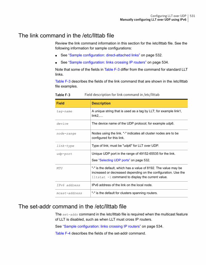
The link command in the /etc/llttab fileReview the link command information in this section for the /etc/llttab file. See thefollowing information for sample configurations:
■ See “Sample configuration: direct-attached links” on page 532.
■ See “Sample configuration: links crossing IP routers” on page 534.
Note that some of the fields in Table F-3 differ from the command for standard LLTlinks.
Table F-3 describes the fields of the link command that are shown in the /etc/llttabfile examples.
Table F-3 Field description for link command in /etc/llttab
DescriptionField
A unique string that is used as a tag by LLT; for example link1,link2,....
tag-name
The device name of the UDP protocol; for example udp6.device
Nodes using the link. "-" indicates all cluster nodes are to beconfigured for this link.
node-range
Type of link; must be "udp6" for LLT over UDP.link-type
Unique UDP port in the range of 49152-65535 for the link.
See “Selecting UDP ports” on page 532.
udp-port
"-" is the default, which has a value of 8192. The value may beincreased or decreased depending on the configuration. Use thelltstat -l command to display the current value.
MTU
IPv6 address of the link on the local node.IPv6 address
"-" is the default for clusters spanning routers.mcast-address
The set-addr command in the /etc/llttab fileThe set-addr command in the /etc/llttab file is required when the multicast featureof LLT is disabled, such as when LLT must cross IP routers.
See “Sample configuration: links crossing IP routers” on page 534.
Table F-4 describes the fields of the set-addr command.
531Configuring LLT over UDPManually configuring LLT over UDP using IPv6
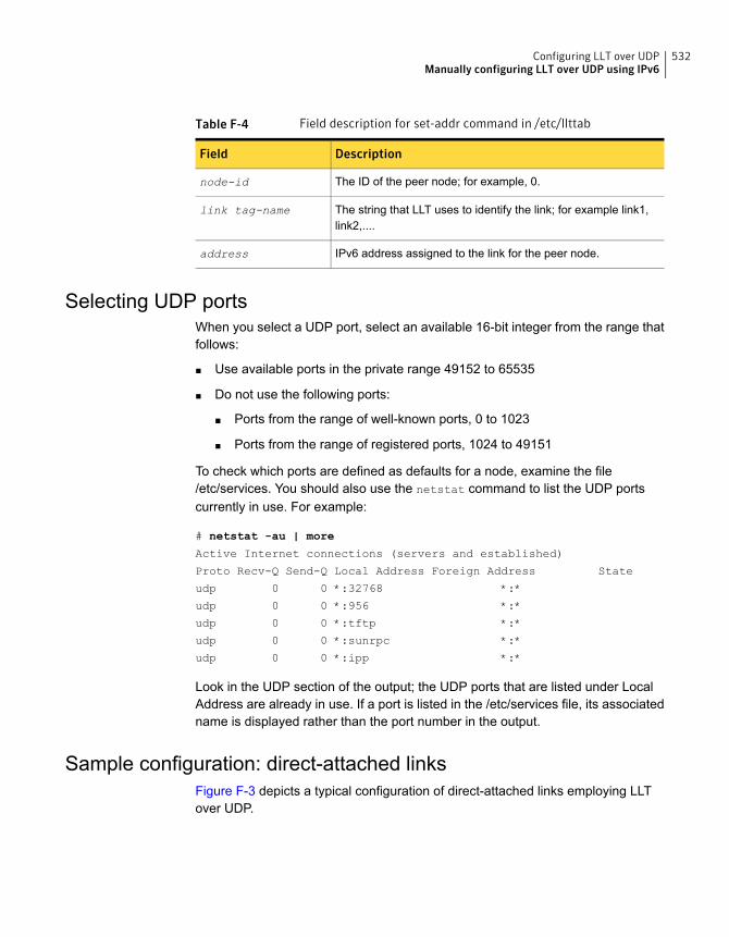
Table F-4 Field description for set-addr command in /etc/llttab
DescriptionField
The ID of the peer node; for example, 0.node-id
The string that LLT uses to identify the link; for example link1,link2,....
link tag-name
IPv6 address assigned to the link for the peer node.address
Selecting UDP portsWhen you select a UDP port, select an available 16-bit integer from the range thatfollows:
■ Use available ports in the private range 49152 to 65535
■ Do not use the following ports:
■ Ports from the range of well-known ports, 0 to 1023
■ Ports from the range of registered ports, 1024 to 49151
To check which ports are defined as defaults for a node, examine the file/etc/services. You should also use the netstat command to list the UDP portscurrently in use. For example:
# netstat -au | more
Active Internet connections (servers and established)
Proto Recv-Q Send-Q Local Address Foreign Address State
udp 0 0 *:32768 *:*
udp 0 0 *:956 *:*
udp 0 0 *:tftp *:*
udp 0 0 *:sunrpc *:*
udp 0 0 *:ipp *:*
Look in the UDP section of the output; the UDP ports that are listed under LocalAddress are already in use. If a port is listed in the /etc/services file, its associatedname is displayed rather than the port number in the output.
Sample configuration: direct-attached linksFigure F-3 depicts a typical configuration of direct-attached links employing LLTover UDP.
532Configuring LLT over UDPManually configuring LLT over UDP using IPv6
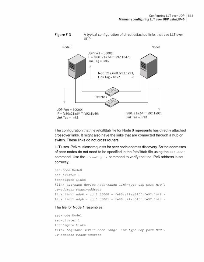
Figure F-3 A typical configuration of direct-attached links that use LLT overUDP
UDP Port = 50001;IP = fe80::21a:64ff:fe92:1b47;Link Tag = link2
UDP Port = 50000;IP = fe80::21a:64ff:fe92:1b46;Link Tag = link1
fe80::21a:64ff:fe92:1a93;Link Tag = link2
fe80::21a:64ff:fe92:1a92;Link Tag = link1
Switches
Node0 Node1
The configuration that the /etc/llttab file for Node 0 represents has directly attachedcrossover links. It might also have the links that are connected through a hub orswitch. These links do not cross routers.
LLT uses IPv6 multicast requests for peer node address discovery. So the addressesof peer nodes do not need to be specified in the /etc/llttab file using the set-addr
command. Use the ifconfig -a command to verify that the IPv6 address is setcorrectly.
set-node Node0
set-cluster 1
#configure Links
#link tag-name device node-range link-type udp port MTU \
IP-address mcast-address
link link1 udp6 - udp6 50000 - fe80::21a:64ff:fe92:1b46 -
link link1 udp6 - udp6 50001 - fe80::21a:64ff:fe92:1b47 -
The file for Node 1 resembles:
set-node Node1
set-cluster 1
#configure Links
#link tag-name device node-range link-type udp port MTU \
IP-address mcast-address
533Configuring LLT over UDPManually configuring LLT over UDP using IPv6
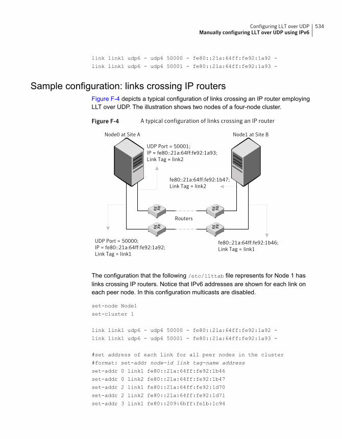
link link1 udp6 - udp6 50000 - fe80::21a:64ff:fe92:1a92 -
link link1 udp6 - udp6 50001 - fe80::21a:64ff:fe92:1a93 -
Sample configuration: links crossing IP routersFigure F-4 depicts a typical configuration of links crossing an IP router employingLLT over UDP. The illustration shows two nodes of a four-node cluster.
Figure F-4 A typical configuration of links crossing an IP router
UDP Port = 50001;IP = fe80::21a:64ff:fe92:1a93;Link Tag = link2
UDP Port = 50000;IP = fe80::21a:64ff:fe92:1a92;Link Tag = link1
fe80::21a:64ff:fe92:1b47;Link Tag = link2
fe80::21a:64ff:fe92:1b46;Link Tag = link1
Routers
Node0 at Site A Node1 at Site B
The configuration that the following /etc/llttab file represents for Node 1 haslinks crossing IP routers. Notice that IPv6 addresses are shown for each link oneach peer node. In this configuration multicasts are disabled.
set-node Node1
set-cluster 1
link link1 udp6 - udp6 50000 - fe80::21a:64ff:fe92:1a92 -
link link1 udp6 - udp6 50001 - fe80::21a:64ff:fe92:1a93 -
#set address of each link for all peer nodes in the cluster
#format: set-addr node-id link tag-name address
set-addr 0 link1 fe80::21a:64ff:fe92:1b46
set-addr 0 link2 fe80::21a:64ff:fe92:1b47
set-addr 2 link1 fe80::21a:64ff:fe92:1d70
set-addr 2 link2 fe80::21a:64ff:fe92:1d71
set-addr 3 link1 fe80::209:6bff:fe1b:1c94
534Configuring LLT over UDPManually configuring LLT over UDP using IPv6
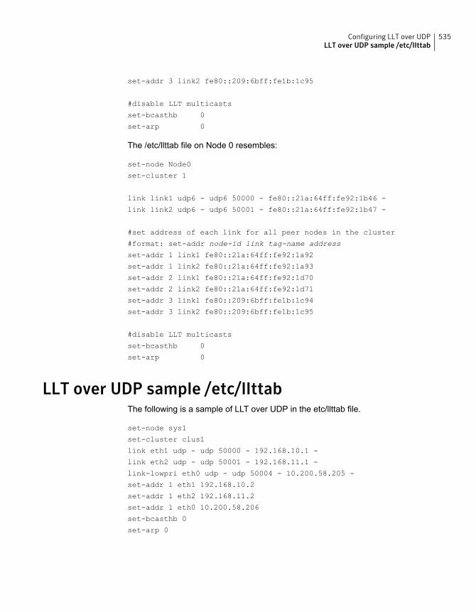
set-addr 3 link2 fe80::209:6bff:fe1b:1c95
#disable LLT multicasts
set-bcasthb 0
set-arp 0
The /etc/llttab file on Node 0 resembles:
set-node Node0
set-cluster 1
link link1 udp6 - udp6 50000 - fe80::21a:64ff:fe92:1b46 -
link link2 udp6 - udp6 50001 - fe80::21a:64ff:fe92:1b47 -
#set address of each link for all peer nodes in the cluster
#format: set-addr node-id link tag-name address
set-addr 1 link1 fe80::21a:64ff:fe92:1a92
set-addr 1 link2 fe80::21a:64ff:fe92:1a93
set-addr 2 link1 fe80::21a:64ff:fe92:1d70
set-addr 2 link2 fe80::21a:64ff:fe92:1d71
set-addr 3 link1 fe80::209:6bff:fe1b:1c94
set-addr 3 link2 fe80::209:6bff:fe1b:1c95
#disable LLT multicasts
set-bcasthb 0
set-arp 0
LLT over UDP sample /etc/llttabThe following is a sample of LLT over UDP in the etc/llttab file.
set-node sys1
set-cluster clus1
link eth1 udp - udp 50000 - 192.168.10.1 -
link eth2 udp - udp 50001 - 192.168.11.1 -
link-lowpri eth0 udp - udp 50004 - 10.200.58.205 -
set-addr 1 eth1 192.168.10.2
set-addr 1 eth2 192.168.11.2
set-addr 1 eth0 10.200.58.206
set-bcasthb 0
set-arp 0
535Configuring LLT over UDPLLT over UDP sample /etc/llttab

Using LLT over RDMA
This appendix includes the following topics:
■ Using LLT over RDMA
■ About RDMA over RoCE or InfiniBand networks in a clustering environment
■ How LLT supports RDMA capability for faster interconnects between applications
■ Using LLT over RDMA: supported use cases
■ Configuring LLT over RDMA
■ Troubleshooting LLT over RDMA
Using LLT over RDMAThis section describes how LLT works with RDMA, lists the hardware requirementsfor RDMA, and the procedure to configure LLT over RDMA.
About RDMA over RoCE or InfiniBand networks in aclustering environment
Remote direct memory access (RDMA) is a direct memory access capability thatallows server to server data movement directly between application memories withminimal CPU involvement. Data transfer using RDMA needs RDMA-enabled networkcards and switches. Networks designed with RDMA over Converged Ethernet(RoCE) and InfiniBand architecture support RDMA capability. RDMA provides fastinterconnect between user-space applications or file systems between nodes overthese networks. In a clustering environment, RDMA capability allows applicationson separate nodes to transfer data at a faster rate with low latency and less CPUusage.
GAppendix
See “How LLT supports RDMA capability for faster interconnects betweenapplications” on page 537.
How LLT supports RDMA capability for fasterinterconnects between applications
LLT and GAB support fast interconnect between applications using RDMAtechnology over InfiniBand and Ethernet media (RoCE). To leverage the RDMAcapabilities of the hardware and also support the existing LLT functionalities, LLTmaintains two channels (RDMA and non-RDMA) for each of the configured RDMAlinks. Both RDMA and non-RDMA channels are capable of transferring data betweenthe nodes and LLT provides separate APIs to their clients, such as, CFS, CVM, touse these channels. The RDMA channel provides faster data transfer by leveragingthe RDMA capabilities of the hardware. The RDMA channel is mainly used fordata-transfer when the client is capable to use this channel. The non-RDMA channelis created over the UDP layer and LLT uses this channel mainly for sending andreceiving heartbeats. Based on the health of the non-RDMA channel, GAB decidescluster membership for the cluster. The connection management of the RDMAchannel is separate from the non-RDMA channel, but the connect and disconnectoperations for the RDMA channel are triggered based on the status of the non-RDMAchannel
If the non-RDMA channel is up but due to some issues in RDMA layer the RDMAchannel is down, in such cases the data-transfer happens over the non-RDMAchannel with a lesser performance until the RDMA channel is fixed. The systemlogs displays the message when the RDMA channel is up or down.
LLT uses the Open Fabrics Enterprise Distribution (OFED) layer and the driversinstalled by the operating system to communicate with the hardware. LLT overRDMA allows applications running on one node to directly access the memory ofan application running on another node that are connected over an RDMA-enablednetwork. In contrast, on nodes connected over a non-RDMA network, applicationscannot directly read or write to an application running on another node. LLT clientssuch as, CFS and CVM, have to create intermediate copies of data beforecompleting the read or write operation on the application, which increases thelatency period and affects performance in some cases.
LLT over an RDMA network enables applications to read or write to applicationson another node over the network without the need to create intermediate copies.This leads to low latency, higher throughput, and minimized CPU host usage thusimproving application performance. Cluster volume manager and Cluster FileSystems, which are clients of LLT and GAB, can use LLT over RDMA capabilityfor specific use cases.
537Using LLT over RDMAHow LLT supports RDMA capability for faster interconnects between applications
See “Using LLT over RDMA: supported use cases ” on page 538.
Using LLT over RDMA: supported use casesYou can configure the LLT over RDMA capability for the following use cases:
■ Storage Foundation Smart IO feature on flash storage devices: The Smart IOfeature provides file system caching on flash devices for increased applicationperformance by reducing IO bottlenecks. It also reduces IO loads on storagecontrollers as the Smart IO feature meets most of the application IO needs. Asthe IO requirements from the storage array are much lesser, you require lessernumber of servers to maintain the same IO throughput.
■ Storage Foundation IO shipping feature: The IO shipping feature in StorageFoundation Cluster File System HA (SFCFSHA) provides the ability to ship IOdata between applications on peer nodes without service interruption even ifthe IO path on one of the nodes in the cluster goes down.
■ Storage Foundation Flexible Storage Sharing feature : The Flexible StorageSharing feature in cluster volume manager allows network shared storage toco-exist with physically shared storage. It provides server administrators theability to provision clusters for Storage Foundation Cluster File System HA(SFCFSHA) and Storage Foundation for Oracle RAC (SFRAC) or SFCFSHAapplications without requiring physical shared storage.
Both Cluster File System (CFS) and Cluster Volume Manager (CVM) are clients ofLLT and GAB. These clients use LLT as the transport protocol for data transferbetween applications on nodes. Using LLT data transfer over an RDMA networkboosts performance of file system data transfer and IO transfer between nodes.
To enable RDMA capability for faster application data transfer between nodes, youmust install RDMA-capable network interface cards, RDMA-supported networkswitches, configure the operating system for RDMA, and configure LLT.
Ensure that you select RDMA-supported hardware and configure LLT to use RDMAfunctionality.
See “Choosing supported hardware for LLT over RDMA” on page 539.
See “Configuring LLT over RDMA” on page 538.
Configuring LLT over RDMAThis section describes the required hardware and configuration needed for LLT tosupport RDMA capability. The high-level steps to configure LLT over RDMA are asfollows:
538Using LLT over RDMAUsing LLT over RDMA: supported use cases
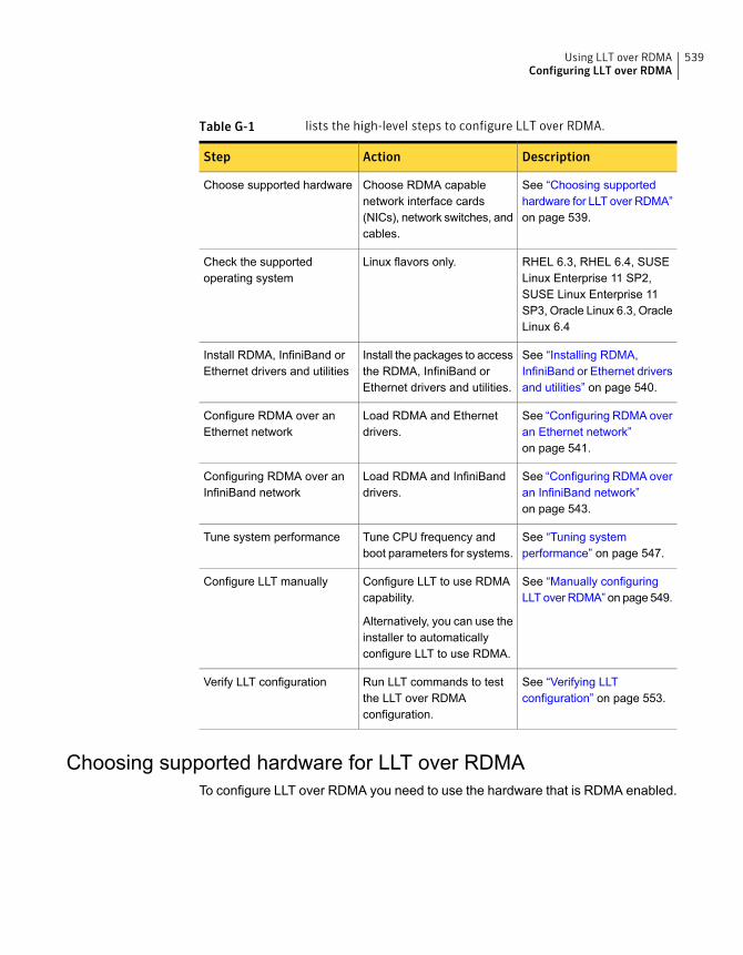
Table G-1 lists the high-level steps to configure LLT over RDMA.
DescriptionActionStep
See “Choosing supportedhardware for LLT over RDMA”on page 539.
Choose RDMA capablenetwork interface cards(NICs), network switches, andcables.
Choose supported hardware
RHEL 6.3, RHEL 6.4, SUSELinux Enterprise 11 SP2,SUSE Linux Enterprise 11SP3, Oracle Linux 6.3, OracleLinux 6.4
Linux flavors only.Check the supportedoperating system
See “Installing RDMA,InfiniBand or Ethernet driversand utilities” on page 540.
Install the packages to accessthe RDMA, InfiniBand orEthernet drivers and utilities.
Install RDMA, InfiniBand orEthernet drivers and utilities
See “Configuring RDMA overan Ethernet network”on page 541.
Load RDMA and Ethernetdrivers.
Configure RDMA over anEthernet network
See “Configuring RDMA overan InfiniBand network”on page 543.
Load RDMA and InfiniBanddrivers.
Configuring RDMA over anInfiniBand network
See “Tuning systemperformance” on page 547.
Tune CPU frequency andboot parameters for systems.
Tune system performance
See “Manually configuringLLT over RDMA” on page 549.
Configure LLT to use RDMAcapability.
Alternatively, you can use theinstaller to automaticallyconfigure LLT to use RDMA.
Configure LLT manually
See “Verifying LLTconfiguration” on page 553.
Run LLT commands to testthe LLT over RDMAconfiguration.
Verify LLT configuration
Choosing supported hardware for LLT over RDMATo configure LLT over RDMA you need to use the hardware that is RDMA enabled.
539Using LLT over RDMAConfiguring LLT over RDMA
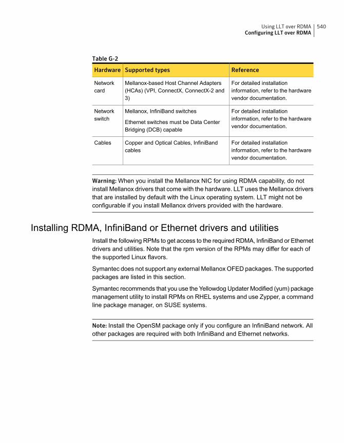
Table G-2
ReferenceSupported typesHardware
For detailed installationinformation, refer to the hardwarevendor documentation.
Mellanox-based Host Channel Adapters(HCAs) (VPI, ConnectX, ConnectX-2 and3)
Networkcard
For detailed installationinformation, refer to the hardwarevendor documentation.
Mellanox, InfiniBand switches
Ethernet switches must be Data CenterBridging (DCB) capable
Networkswitch
For detailed installationinformation, refer to the hardwarevendor documentation.
Copper and Optical Cables, InfiniBandcables
Cables
Warning: When you install the Mellanox NIC for using RDMA capability, do notinstall Mellanox drivers that come with the hardware. LLT uses the Mellanox driversthat are installed by default with the Linux operating system. LLT might not beconfigurable if you install Mellanox drivers provided with the hardware.
Installing RDMA, InfiniBand or Ethernet drivers and utilitiesInstall the following RPMs to get access to the required RDMA, InfiniBand or Ethernetdrivers and utilities. Note that the rpm version of the RPMs may differ for each ofthe supported Linux flavors.
Symantec does not support any external Mellanox OFED packages. The supportedpackages are listed in this section.
Symantec recommends that you use the Yellowdog Updater Modified (yum) packagemanagement utility to install RPMs on RHEL systems and use Zypper, a commandline package manager, on SUSE systems.
Note: Install the OpenSM package only if you configure an InfiniBand network. Allother packages are required with both InfiniBand and Ethernet networks.
540Using LLT over RDMAConfiguring LLT over RDMA
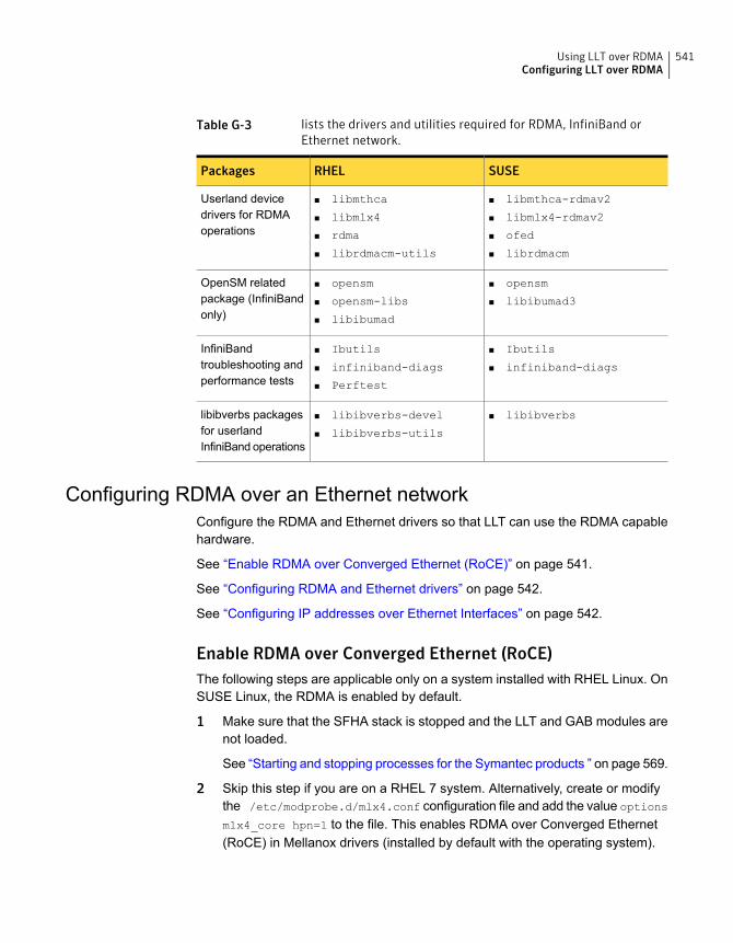
Table G-3 lists the drivers and utilities required for RDMA, InfiniBand orEthernet network.
SUSERHELPackages
■ libmthca-rdmav2
■ libmlx4-rdmav2
■ ofed
■ librdmacm
■ libmthca
■ libmlx4
■ rdma
■ librdmacm-utils
Userland devicedrivers for RDMAoperations
■ opensm
■ libibumad3
■ opensm
■ opensm-libs
■ libibumad
OpenSM relatedpackage (InfiniBandonly)
■ Ibutils
■ infiniband-diags
■ Ibutils
■ infiniband-diags
■ Perftest
InfiniBandtroubleshooting andperformance tests
■ libibverbs■ libibverbs-devel
■ libibverbs-utils
libibverbs packagesfor userlandInfiniBand operations
Configuring RDMA over an Ethernet networkConfigure the RDMA and Ethernet drivers so that LLT can use the RDMA capablehardware.
See “Enable RDMA over Converged Ethernet (RoCE)” on page 541.
See “Configuring RDMA and Ethernet drivers” on page 542.
See “Configuring IP addresses over Ethernet Interfaces” on page 542.
Enable RDMA over Converged Ethernet (RoCE)The following steps are applicable only on a system installed with RHEL Linux. OnSUSE Linux, the RDMA is enabled by default.
1 Make sure that the SFHA stack is stopped and the LLT and GAB modules arenot loaded.
See “Starting and stopping processes for the Symantec products ” on page 569.
2 Skip this step if you are on a RHEL 7 system. Alternatively, create or modifythe /etc/modprobe.d/mlx4.conf configuration file and add the value options
mlx4_core hpn=1 to the file. This enables RDMA over Converged Ethernet(RoCE) in Mellanox drivers (installed by default with the operating system).
541Using LLT over RDMAConfiguring LLT over RDMA

3 Verify whether the Mellanox drivers are loaded.
# lsmod | grep mlx4_en
# lsmod | grep mlx4_core
4 Unload the Mellanox drivers if the drivers are loaded.
# rmmod mlx4_ib
# rmmod mlx4_en
# rmmod mlx4_core
Configuring RDMA and Ethernet driversLoad the Mellanox drivers that are installed by default with the operating systemand enable the RDMA service.
1 (RHEL Linux only) Load the Mellanox drivers.
# modprobe mlx4_core
# modprobe mlx4_ib
# modprobe mlx4_en
2 Enable RDMA service on the Linux operating system.
On RHEL Linux: # chkconfig --level 235 rdma on
On SUSE Linux: # chkconfig --level 235 openibd on
Configuring IP addresses over Ethernet InterfacesPerform the following steps to configure IP addresses over the network interfaceswhich you plan to configure under LLT. These interfaces must not be aggregatedinterfaces.
542Using LLT over RDMAConfiguring LLT over RDMA
1 Configure IP addresses using Linux ifconfig command. Make sure that theIP address for each link must be from a different subnet.
Typical private IP addresses that you can use are:
Node0:
link0: 192.168.1.1
link1: 192.168.2.1
Node1:
link0: 192.168.1.2
link1: 192.168.2.2
2 Run IP ping test between nodes to ensure that there is network levelconnectivity between nodes.
3 Configure IP addresses to start automatically after the system restarts or rebootsby creating a new configuration file or by modifying the existing file.
■ On RHEL, modify the /etc/sysconfig/network-scripts/ directory bymodifying the ifcfg-eth (Ethernet) configuration file.
■ On SUSE, modify the /etc/sysconfig/network/ by modifying theifcfg-eth (Ethernet) configuration file.For example, for an Ethernet interface eth0, create the ifcfg-eth0 file withvalues for the following parameters.
DEVICE=eth0
BOOTPROTO=static
IPADDR=192.168.27.1
NETMASK=255.255.255.0
NETWORK=192.168.27.0
BROADCAST=192.168.27.255
NM_CONTROLLED=no # This line ensures IPs are plumbed correctly after bootup
ONBOOT=yes
STARTMODE='auto' # This line is only for SUSE
Configuring RDMA over an InfiniBand networkWhile configuring RDMA over an InfiniBand network, you need to configure theInfiniBand drivers, configure the OpenSM service, and configure IP addresses forthe InfiniBand interfaces.
See “Configuring RDMA and InfiniBand drivers” on page 544.
543Using LLT over RDMAConfiguring LLT over RDMA
See “ Configuring the OpenSM service” on page 545.
See “Configuring IP addresses over InfiniBand Interfaces” on page 546.
Configuring RDMA and InfiniBand driversConfigure the RDMA and InfiniBand drivers so that LLT can use the RDMA capablehardware.
544Using LLT over RDMAConfiguring LLT over RDMA
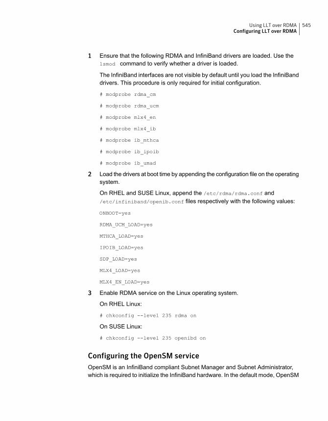
1 Ensure that the following RDMA and InfiniBand drivers are loaded. Use thelsmod command to verify whether a driver is loaded.
The InfiniBand interfaces are not visible by default until you load the InfiniBanddrivers. This procedure is only required for initial configuration.
# modprobe rdma_cm
# modprobe rdma_ucm
# modprobe mlx4_en
# modprobe mlx4_ib
# modprobe ib_mthca
# modprobe ib_ipoib
# modprobe ib_umad
2 Load the drivers at boot time by appending the configuration file on the operatingsystem.
On RHEL and SUSE Linux, append the /etc/rdma/rdma.conf and/etc/infiniband/openib.conf files respectively with the following values:
ONBOOT=yes
RDMA_UCM_LOAD=yes
MTHCA_LOAD=yes
IPOIB_LOAD=yes
SDP_LOAD=yes
MLX4_LOAD=yes
MLX4_EN_LOAD=yes
3 Enable RDMA service on the Linux operating system.
On RHEL Linux:
# chkconfig --level 235 rdma on
On SUSE Linux:
# chkconfig --level 235 openibd on
Configuring the OpenSM serviceOpenSM is an InfiniBand compliant Subnet Manager and Subnet Administrator,which is required to initialize the InfiniBand hardware. In the default mode, OpenSM
545Using LLT over RDMAConfiguring LLT over RDMA
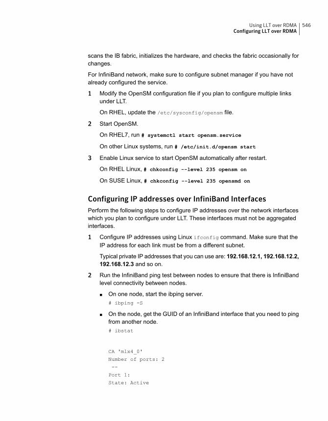
scans the IB fabric, initializes the hardware, and checks the fabric occasionally forchanges.
For InfiniBand network, make sure to configure subnet manager if you have notalready configured the service.
1 Modify the OpenSM configuration file if you plan to configure multiple linksunder LLT.
On RHEL, update the /etc/sysconfig/opensm file.
2 Start OpenSM.
On RHEL7, run # systemctl start opensm.service
On other Linux systems, run # /etc/init.d/opensm start
3 Enable Linux service to start OpenSM automatically after restart.
On RHEL Linux, # chkconfig --level 235 opensm on
On SUSE Linux, # chkconfig --level 235 opensmd on
Configuring IP addresses over InfiniBand InterfacesPerform the following steps to configure IP addresses over the network interfaceswhich you plan to configure under LLT. These interfaces must not be aggregatedinterfaces.
1 Configure IP addresses using Linux ifconfig command. Make sure that theIP address for each link must be from a different subnet.
Typical private IP addresses that you can use are: 192.168.12.1, 192.168.12.2,192.168.12.3 and so on.
2 Run the InfiniBand ping test between nodes to ensure that there is InfiniBandlevel connectivity between nodes.
■ On one node, start the ibping server.# ibping -S
■ On the node, get the GUID of an InfiniBand interface that you need to pingfrom another node.# ibstat
CA 'mlx4_0'
Number of ports: 2
--
Port 1:
State: Active
546Using LLT over RDMAConfiguring LLT over RDMA
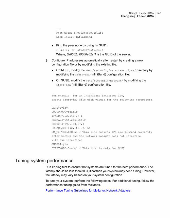
---
Port GUID: 0x0002c90300a02af1
Link layer: InfiniBand
■ Ping the peer node by using its GUID.# ibping -G 0x0002c90300a02af1
Where, 0x0002c90300a02af1 is the GUID of the server.
3 Configure IP addresses automatically after restart by creating a newconfiguration file or by modifying the existing file.
■ On RHEL, modify the /etc/sysconfig/network-scripts/ directory bymodifying the ifcfg-ibX (InfiniBand) configuration file.
■ On SUSE, modify the /etc/sysconfig/network/ by modifying theifcfg-ibX (InfiniBand) configuration file.
For example, for an Infiniband interface ib0,
create ifcfg-ib0 file with values for the following parameters.
DEVICE=ib0
BOOTPROTO=static
IPADDR=192.168.27.1
NETMASK=255.255.255.0
NETWORK=192.168.27.0
BROADCAST=192.168.27.255
NM_CONTROLLED=no # This line ensures IPs are plumbed correctly
after bootup and the Network manager does not interfere
with the interfaces
ONBOOT=yes
STARTMODE='auto' # This line is only for SUSE
Tuning system performanceRun IP ping test to ensure that systems are tuned for the best performance. Thelatency should be less than 30us, if not then your system may need tuning. However,the latency may vary based on your system configuration.
To tune your system, perform the following steps. For additional tuning, follow theperformance tuning guide from Mellanox.
Performance Tuning Guidelines for Mellanox Network Adapters
547Using LLT over RDMAConfiguring LLT over RDMA

Tuning the CPU frequencyTo tune the CPU frequency of a system, perform the following steps:
1 Verify whether the CPU frequency is already tuned.
# cat /proc/cpuinfo | grep Hz
model name : Intel(R) Xeon(R) CPU E5-2643 0 @ 3.30GHz
cpu MHz : 3300.179
2 If the CPU frquency displayed by the cpu MHz and model name attribute is thesame, then the CPU frequency is already tuned. You can skip the next steps.
If the CPU frequency displayed by the cpu Mhz and model name attribute isnot the same, then follow the next steps to tune the frequency.
3 Go to system console and restart the system.
4 Press F11 to enter into BIOS settings.
5 Go to BIOS menu > Launch System setup > BIOS settings > System ProfileSettings > System Profile > Max performance.
The menu options might vary with system type.
Tuning the boot parameter settingsTo tune the boot parameter settings, perform the following steps.
1 In the /boot/grub/grub.conf file or any other boot loader configuration file,ensure that the value of the intel_iommu is set to off.
2 Append the /boot/grub/grub.conf file or any other boot loader configurationfile with the following parameters if they are not listed in the configuration file.
intel_idle.max_cstate=0 processor.max_cstate=1
3 Restart the system.
On RHEL 7 systems:
1 In the /etc/default/grub file, append the GRUB_CMDLINE_LINUX variablewith intel_idle.max_cstate=0 processor.max_cstate=1
2 After /etc/default/grub is modified, run the following command:
grub2-mkconfig -o /boot/grub2/grub.cfg
3 Restart the system.
548Using LLT over RDMAConfiguring LLT over RDMA
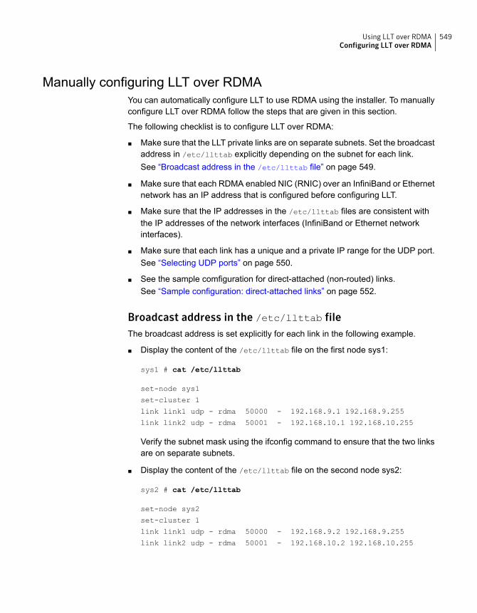
Manually configuring LLT over RDMAYou can automatically configure LLT to use RDMA using the installer. To manuallyconfigure LLT over RDMA follow the steps that are given in this section.
The following checklist is to configure LLT over RDMA:
■ Make sure that the LLT private links are on separate subnets. Set the broadcastaddress in /etc/llttab explicitly depending on the subnet for each link.See “Broadcast address in the /etc/llttab file” on page 549.
■ Make sure that each RDMA enabled NIC (RNIC) over an InfiniBand or Ethernetnetwork has an IP address that is configured before configuring LLT.
■ Make sure that the IP addresses in the /etc/llttab files are consistent withthe IP addresses of the network interfaces (InfiniBand or Ethernet networkinterfaces).
■ Make sure that each link has a unique and a private IP range for the UDP port.See “Selecting UDP ports” on page 550.
■ See the sample comfiguration for direct-attached (non-routed) links.See “Sample configuration: direct-attached links” on page 552.
Broadcast address in the /etc/llttab fileThe broadcast address is set explicitly for each link in the following example.
■ Display the content of the /etc/llttab file on the first node sys1:
sys1 # cat /etc/llttab
set-node sys1
set-cluster 1
link link1 udp - rdma 50000 - 192.168.9.1 192.168.9.255
link link2 udp - rdma 50001 - 192.168.10.1 192.168.10.255
Verify the subnet mask using the ifconfig command to ensure that the two linksare on separate subnets.
■ Display the content of the /etc/llttab file on the second node sys2:
sys2 # cat /etc/llttab
set-node sys2
set-cluster 1
link link1 udp - rdma 50000 - 192.168.9.2 192.168.9.255
link link2 udp - rdma 50001 - 192.168.10.2 192.168.10.255
549Using LLT over RDMAConfiguring LLT over RDMA
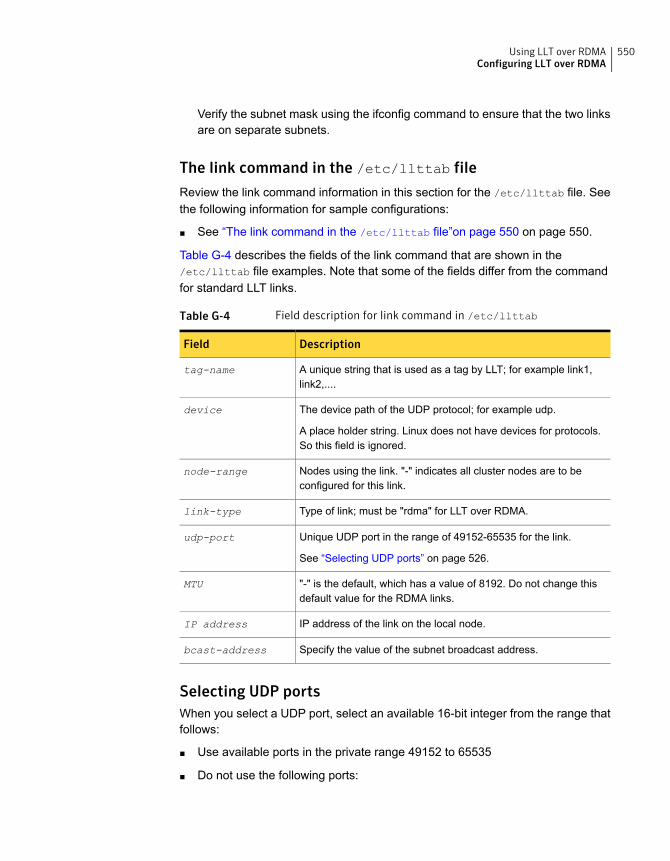
Verify the subnet mask using the ifconfig command to ensure that the two linksare on separate subnets.
The link command in the /etc/llttab fileReview the link command information in this section for the /etc/llttab file. Seethe following information for sample configurations:
■ See “The link command in the /etc/llttab file”on page 550 on page 550.
Table G-4 describes the fields of the link command that are shown in the/etc/llttab file examples. Note that some of the fields differ from the commandfor standard LLT links.
Table G-4 Field description for link command in /etc/llttab
DescriptionField
A unique string that is used as a tag by LLT; for example link1,link2,....
tag-name
The device path of the UDP protocol; for example udp.
A place holder string. Linux does not have devices for protocols.So this field is ignored.
device
Nodes using the link. "-" indicates all cluster nodes are to beconfigured for this link.
node-range
Type of link; must be "rdma" for LLT over RDMA.link-type
Unique UDP port in the range of 49152-65535 for the link.
See “Selecting UDP ports” on page 526.
udp-port
"-" is the default, which has a value of 8192. Do not change thisdefault value for the RDMA links.
MTU
IP address of the link on the local node.IP address
Specify the value of the subnet broadcast address.bcast-address
Selecting UDP portsWhen you select a UDP port, select an available 16-bit integer from the range thatfollows:
■ Use available ports in the private range 49152 to 65535
■ Do not use the following ports:
550Using LLT over RDMAConfiguring LLT over RDMA
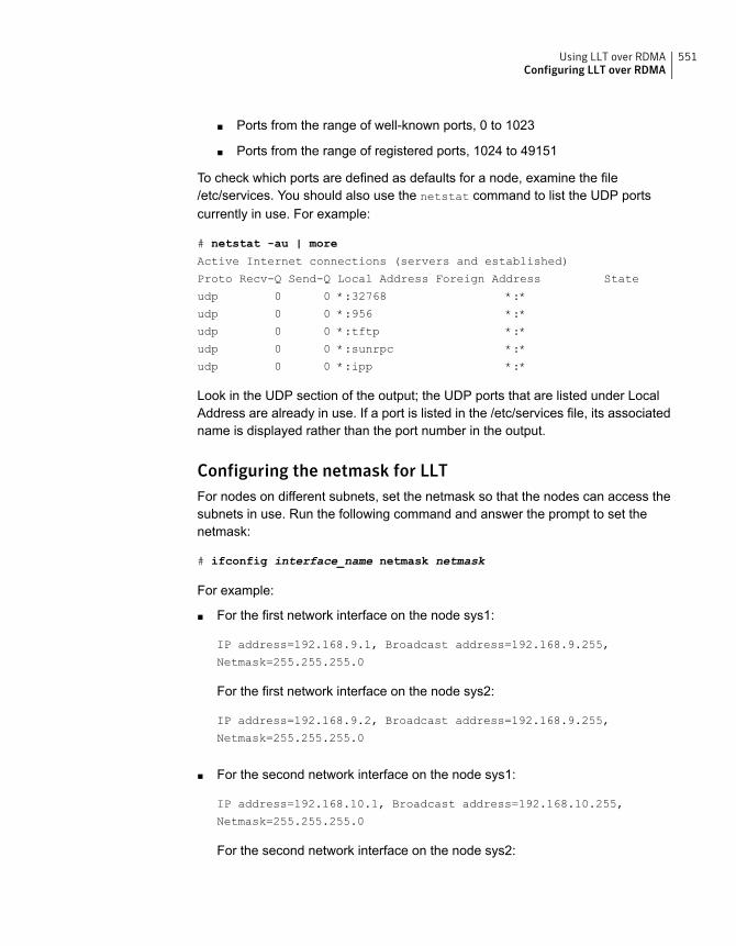
Ports from the range of well-known ports, 0 to 1023■
■ Ports from the range of registered ports, 1024 to 49151
To check which ports are defined as defaults for a node, examine the file/etc/services. You should also use the netstat command to list the UDP portscurrently in use. For example:
# netstat -au | more
Active Internet connections (servers and established)
Proto Recv-Q Send-Q Local Address Foreign Address State
udp 0 0 *:32768 *:*
udp 0 0 *:956 *:*
udp 0 0 *:tftp *:*
udp 0 0 *:sunrpc *:*
udp 0 0 *:ipp *:*
Look in the UDP section of the output; the UDP ports that are listed under LocalAddress are already in use. If a port is listed in the /etc/services file, its associatedname is displayed rather than the port number in the output.
Configuring the netmask for LLTFor nodes on different subnets, set the netmask so that the nodes can access thesubnets in use. Run the following command and answer the prompt to set thenetmask:
# ifconfig interface_name netmask netmask
For example:
■ For the first network interface on the node sys1:
IP address=192.168.9.1, Broadcast address=192.168.9.255,
Netmask=255.255.255.0
For the first network interface on the node sys2:
IP address=192.168.9.2, Broadcast address=192.168.9.255,
Netmask=255.255.255.0
■ For the second network interface on the node sys1:
IP address=192.168.10.1, Broadcast address=192.168.10.255,
Netmask=255.255.255.0
For the second network interface on the node sys2:
551Using LLT over RDMAConfiguring LLT over RDMA
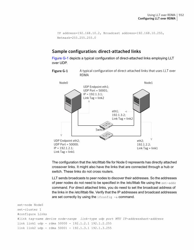
IP address=192.168.10.2, Broadcast address=192.168.10.255,
Netmask=255.255.255.0
Sample configuration: direct-attached linksFigure G-1 depicts a typical configuration of direct-attached links employing LLTover UDP.
Figure G-1 A typical configuration of direct-attached links that uses LLT overRDMA
UDP Endpoint eth1;UDP Port = 50001;IP = 192.1.3.1;Link Tag = link2
UDP Endpoint eth2;UDP Port = 50000;IP = 192.1.2.1;Link Tag = link1
eth1;192.1.3.2;Link Tag = link2
eth2;192.1.2.2;Link Tag = link1
Switch
Node0 Node1
The configuration that the /etc/llttab file for Node 0 represents has directly attachedcrossover links. It might also have the links that are connected through a hub orswitch. These links do not cross routers.
LLT sends broadcasts to peer nodes to discover their addresses. So the addressesof peer nodes do not need to be specified in the /etc/llttab file using the set-addr
command. For direct attached links, you do need to set the broadcast address ofthe links in the /etc/llttab file. Verify that the IP addresses and broadcast addressesare set correctly by using the ifconfig -a command.
set-node Node0
set-cluster 1
#configure Links
#link tag-name device node-range link-type udp port MTU IP-addressbast-address
link link1 udp - rdma 50000 - 192.1.2.1 192.1.2.255
link link2 udp - rdma 50001 - 192.1.3.1 192.1.3.255
552Using LLT over RDMAConfiguring LLT over RDMA

The file for Node 1 resembles:
set-node Node1
set-cluster 1
#configure Links
#link tag-name device node-range link-type udp port MTU IP-address bast-address
link link1 udp - rdma 50000 - 192.1.2.2 192.1.2.255
link link2 udp - rdma 50001 - 192.1.3.2 192.1.3.255
LLT over RDMA sample /etc/llttabThe following is a sample of LLT over RDMA in the etc/llttab file.
set-node sys1
set-cluster clus1
link eth1 udp - rdma 50000 - 192.168.10.1 - 192.168.10.255
link eth2 udp - rdma 50001 - 192.168.11.1 - 192.168.11.255
link-lowpri eth0 udp - rdma 50004 - 10.200.58.205 - 10.200.58.255
Verifying LLT configurationAfter starting LLT, GAB and other component, run the following commands to verifythe LLT configuration.
553Using LLT over RDMAConfiguring LLT over RDMA
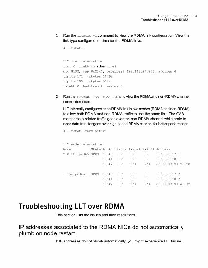
1 Run the lltstat -l command to view the RDMA link configuration. View thelink-type configured to rdma for the RDMA links.
# lltstat -l
LLT link information:
link 0 link0 on rdma hipri
mtu 8192, sap 0x2345, broadcast 192.168.27.255, addrlen 4
txpkts 171 txbytes 10492
rxpkts 105 rxbytes 5124
latehb 0 badcksum 0 errors 0
2 Run the lltstat -nvv -r command to view the RDMA and non-RDMA channelconnection state.
LLT internally configures each RDMA link in two modes (RDMA and non-RDMA)to allow both RDMA and non-RDMA traffic to use the same link. The GABmembership-related traffic goes over the non-RDMA channel while node tonode data-transfer goes over high-speed RDMA channel for better performance.
# lltstat -rnvv active
LLT node information:
Node State Link Status TxRDMA RxRDMA Address
* 0 thorpc365 OPEN link0 UP UP UP 192.168.27.1
link1 UP UP UP 192.168.28.1
link2 UP N/A N/A 00:15:17:97:91:2E
1 thorpc366 OPEN link0 UP UP UP 192.168.27.2
link1 UP UP UP 192.168.28.2
link2 UP N/A N/A 00:15:17:97:A1:7C
Troubleshooting LLT over RDMAThis section lists the issues and their resolutions.
IP addresses associated to the RDMA NICs do not automaticallyplumb on node restart
If IP addresses do not plumb automatically, you might experience LLT failure.
554Using LLT over RDMATroubleshooting LLT over RDMA
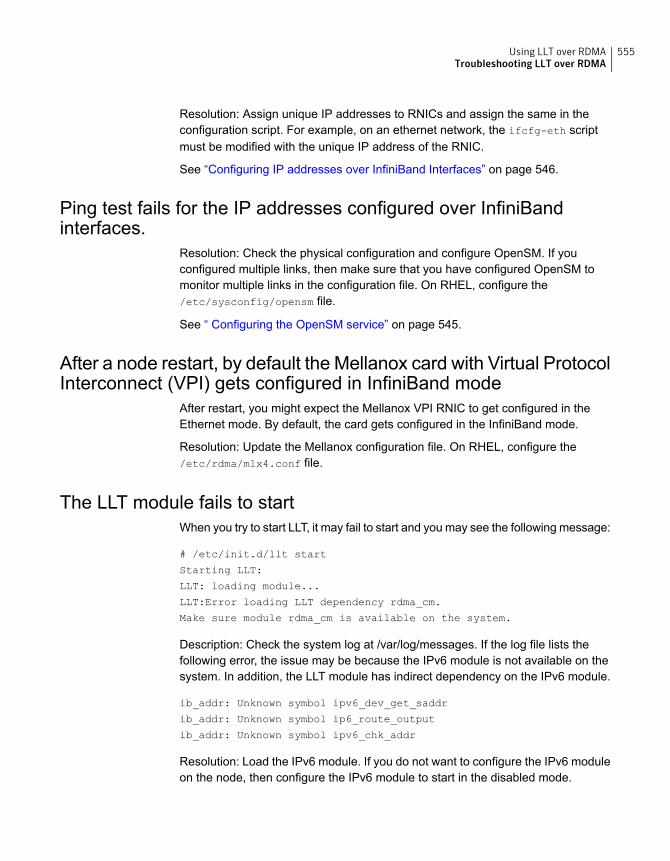
Resolution: Assign unique IP addresses to RNICs and assign the same in theconfiguration script. For example, on an ethernet network, the ifcfg-eth scriptmust be modified with the unique IP address of the RNIC.
See “Configuring IP addresses over InfiniBand Interfaces” on page 546.
Ping test fails for the IP addresses configured over InfiniBandinterfaces.
Resolution: Check the physical configuration and configure OpenSM. If youconfigured multiple links, then make sure that you have configured OpenSM tomonitor multiple links in the configuration file. On RHEL, configure the/etc/sysconfig/opensm file.
See “ Configuring the OpenSM service” on page 545.
After a node restart, by default the Mellanox card with Virtual ProtocolInterconnect (VPI) gets configured in InfiniBand mode
After restart, you might expect the Mellanox VPI RNIC to get configured in theEthernet mode. By default, the card gets configured in the InfiniBand mode.
Resolution: Update the Mellanox configuration file. On RHEL, configure the/etc/rdma/mlx4.conf file.
The LLT module fails to startWhen you try to start LLT, it may fail to start and you may see the following message:
# /etc/init.d/llt start
Starting LLT:
LLT: loading module...
LLT:Error loading LLT dependency rdma_cm.
Make sure module rdma_cm is available on the system.
Description: Check the system log at /var/log/messages. If the log file lists thefollowing error, the issue may be because the IPv6 module is not available on thesystem. In addition, the LLT module has indirect dependency on the IPv6 module.
ib_addr: Unknown symbol ipv6_dev_get_saddr
ib_addr: Unknown symbol ip6_route_output
ib_addr: Unknown symbol ipv6_chk_addr
Resolution: Load the IPv6 module. If you do not want to configure the IPv6 moduleon the node, then configure the IPv6 module to start in the disabled mode.
555Using LLT over RDMATroubleshooting LLT over RDMA

To start IPv6 in the disabled mode:
◆ In the /etc/modprobe.d/ directory, create a file ipv6.conf and add thefollowing line to the file
options ipv6 disable=1
The LLT module starts up without any issues once the file loads the IPv6 modulein the disabled mode.
556Using LLT over RDMATroubleshooting LLT over RDMA
Configuring the secure shellor the remote shell forcommunications
This appendix includes the following topics:
■ About configuring secure shell or remote shell communication modes beforeinstalling products
■ Manually configuring passwordless ssh
■ Setting up ssh and rsh connection using the installer -comsetup command
■ Setting up ssh and rsh connection using the pwdutil.pl utility
■ Restarting the ssh session
■ Enabling rsh for Linux
About configuring secure shell or remote shellcommunication modes before installing products
Establishing communication between nodes is required to install Symantec softwarefrom a remote system, or to install and configure a cluster. The node from whichthe installer is run must have permissions to run rsh (remote shell) or ssh (secureshell) utilities. You need to run the installer with superuser privileges on the systemswhere you plan to install Symantec software.
You can install products to remote systems using either secure shell (ssh) or remoteshell (rsh). Symantec recommends that you use ssh as it is more secure than rsh.
HAppendix
You can set up ssh and rsh connections in many ways.
■ You can manually set up the SSH and RSH connection with UNIX shellcommands.
■ You can run the installer -comsetup command to interactively set up SSHand RSH connection.
■ You can run the password utility, pwdutil.pl.
This section contains an example of how to set up ssh password free communication.The example sets up ssh between a source system (sys1) that contains theinstallation directories, and a target system (sys2). This procedure also applies tomultiple target systems.
Note: The script- and web-based installers support establishing passwordlesscommunication for you.
Manually configuring passwordless sshThe ssh program enables you to log into and execute commands on a remotesystem. ssh enables encrypted communications and an authentication processbetween two untrusted hosts over an insecure network.
In this procedure, you first create a DSA key pair. From the key pair, you appendthe public key from the source system to the authorized_keys file on the targetsystems.
Read the ssh documentation and online manual pages before enabling ssh. Contactyour operating system support provider for issues regarding ssh configuration.
Visit the OpenSSH website that is located at: http://openssh.org to access onlinemanuals and other resources.
To create the DSA key pair
1 On the source system (sys1), log in as root, and navigate to the root directory.
sys1 # cd /root
2 To generate a DSA key pair on the source system, type the following command:
sys1 # ssh-keygen -t dsa
System output similar to the following is displayed:
Generating public/private dsa key pair.
Enter file in which to save the key (/root/.ssh/id_dsa):
558Configuring the secure shell or the remote shell for communicationsManually configuring passwordless ssh
3 Press Enter to accept the default location of /root/.ssh/id_dsa.
4 When the program asks you to enter the passphrase, press the Enter key twice.
Enter passphrase (empty for no passphrase):
Do not enter a passphrase. Press Enter.
Enter same passphrase again:
Press Enter again.
5 Output similar to the following lines appears.
Your identification has been saved in /root/.ssh/id_dsa.
Your public key has been saved in /root/.ssh/id_dsa.pub.
The key fingerprint is:
1f:00:e0:c2:9b:4e:29:b4:0b:6e:08:f8:50:de:48:d2 root@sys1
To append the public key from the source system to the authorized_keys file onthe target system, using secure file transfer
1 From the source system (sys1), move the public key to a temporary file on thetarget system (sys2).
Use the secure file transfer program.
In this example, the file name id_dsa.pub in the root directory is the name forthe temporary file for the public key.
Use the following command for secure file transfer:
sys1 # sftp sys2
If the secure file transfer is set up for the first time on this system, output similarto the following lines is displayed:
Connecting to sys2 ...
The authenticity of host 'sys2 (10.182.00.00)'
can't be established. DSA key fingerprint is
fb:6f:9f:61:91:9d:44:6b:87:86:ef:68:a6:fd:88:7d.
Are you sure you want to continue connecting (yes/no)?
2 Enter yes.
Output similar to the following is displayed:
Warning: Permanently added 'sys2,10.182.00.00'
(DSA) to the list of known hosts.
root@sys2 password:
559Configuring the secure shell or the remote shell for communicationsManually configuring passwordless ssh

3 Enter the root password of sys2.
4 At the sftp prompt, type the following command:
sftp> put /root/.ssh/id_dsa.pub
The following output is displayed:
Uploading /root/.ssh/id_dsa.pub to /root/id_dsa.pub
5 To quit the SFTP session, type the following command:
sftp> quit
6 Add the id_dsa.pub keys to the authorized_keys file on the target system.To begin the ssh session on the target system (sys2 in this example), type thefollowing command on sys1:
sys1 # ssh sys2
Enter the root password of sys2 at the prompt:
password:
Type the following commands on sys2:
sys2 # cat /root/id_dsa.pub >> /root/.ssh/authorized_keys
sys2 # rm /root/id_dsa.pub
7 Run the following commands on the source installation system. If your sshsession has expired or terminated, you can also run these commands to renewthe session. These commands bring the private key into the shell environmentand make the key globally available to the user root:
sys1 # exec /usr/bin/ssh-agent $SHELL
sys1 # ssh-add
Identity added: /root/.ssh/id_dsa
This shell-specific step is valid only while the shell is active. You must executethe procedure again if you close the shell during the session.
560Configuring the secure shell or the remote shell for communicationsManually configuring passwordless ssh
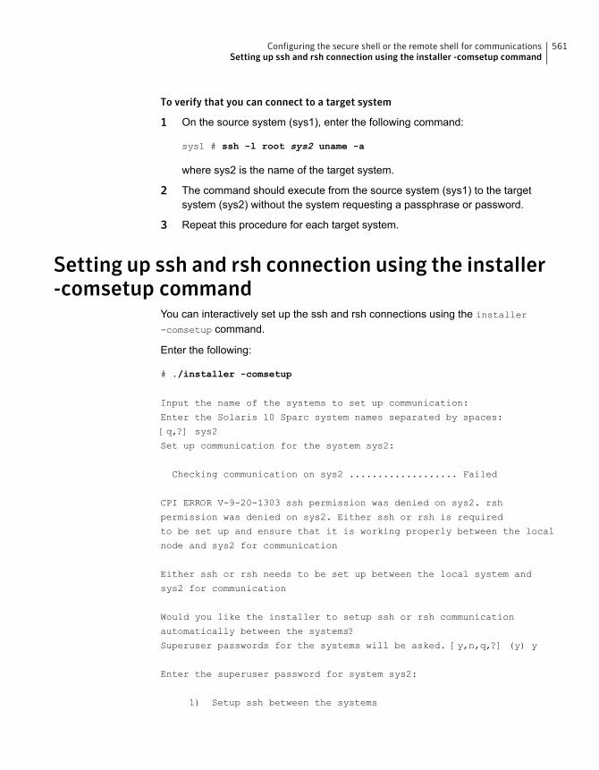
To verify that you can connect to a target system
1 On the source system (sys1), enter the following command:
sys1 # ssh -l root sys2 uname -a
where sys2 is the name of the target system.
2 The command should execute from the source system (sys1) to the targetsystem (sys2) without the system requesting a passphrase or password.
3 Repeat this procedure for each target system.
Setting up ssh and rsh connection using the installer-comsetup command
You can interactively set up the ssh and rsh connections using the installer
-comsetup command.
Enter the following:
# ./installer -comsetup
Input the name of the systems to set up communication:
Enter the Solaris 10 Sparc system names separated by spaces:
[q,?] sys2
Set up communication for the system sys2:
Checking communication on sys2 ................... Failed
CPI ERROR V-9-20-1303 ssh permission was denied on sys2. rsh
permission was denied on sys2. Either ssh or rsh is required
to be set up and ensure that it is working properly between the local
node and sys2 for communication
Either ssh or rsh needs to be set up between the local system and
sys2 for communication
Would you like the installer to setup ssh or rsh communication
automatically between the systems?
Superuser passwords for the systems will be asked. [y,n,q,?] (y) y
Enter the superuser password for system sys2:
1) Setup ssh between the systems
561Configuring the secure shell or the remote shell for communicationsSetting up ssh and rsh connection using the installer -comsetup command

2) Setup rsh between the systems
b) Back to previous menu
Select the communication method [1-2,b,q,?] (1) 1
Setting up communication between systems. Please wait.
Re-verifying systems.
Checking communication on sys2 ..................... Done
Successfully set up communication for the system sys2
Settingup ssh and rsh connectionusing thepwdutil.plutility
The password utility, pwdutil.pl, is bundled in the 6.2 release under the scripts
directory. The users can run the utility in their script to set up the ssh and rshconnection automatically.
# ./pwdutil.pl -h
Usage:
Command syntax with simple format:
pwdutil.pl check|configure|unconfigure ssh|rsh <hostname|IP addr>
[<user>] [<password>] [<port>]
Command syntax with advanced format:
pwdutil.pl [--action|-a 'check|configure|unconfigure']
[--type|-t 'ssh|rsh']
[--user|-u '<user>']
[--password|-p '<password>']
[--port|-P '<port>']
[--hostfile|-f '<hostfile>']
[--keyfile|-k '<keyfile>']
[-debug|-d]
<host_URI>
pwdutil.pl -h | -?
562Configuring the secure shell or the remote shell for communicationsSetting up ssh and rsh connection using the pwdutil.pl utility
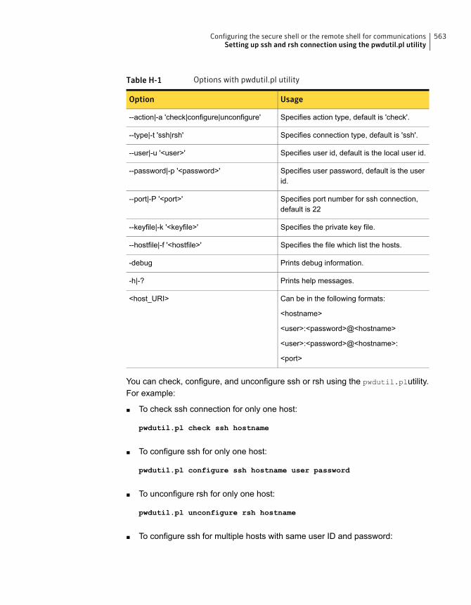
Table H-1 Options with pwdutil.pl utility
UsageOption
Specifies action type, default is 'check'.--action|-a 'check|configure|unconfigure'
Specifies connection type, default is 'ssh'.--type|-t 'ssh|rsh'
Specifies user id, default is the local user id.--user|-u '<user>'
Specifies user password, default is the userid.
--password|-p '<password>'
Specifies port number for ssh connection,default is 22
--port|-P '<port>'
Specifies the private key file.--keyfile|-k '<keyfile>'
Specifies the file which list the hosts.--hostfile|-f '<hostfile>'
Prints debug information.-debug
Prints help messages.-h|-?
Can be in the following formats:
<hostname>
<user>:<password>@<hostname>
<user>:<password>@<hostname>:
<port>
<host_URI>
You can check, configure, and unconfigure ssh or rsh using the pwdutil.plutility.For example:
■ To check ssh connection for only one host:
pwdutil.pl check ssh hostname
■ To configure ssh for only one host:
pwdutil.pl configure ssh hostname user password
■ To unconfigure rsh for only one host:
pwdutil.pl unconfigure rsh hostname
■ To configure ssh for multiple hosts with same user ID and password:
563Configuring the secure shell or the remote shell for communicationsSetting up ssh and rsh connection using the pwdutil.pl utility
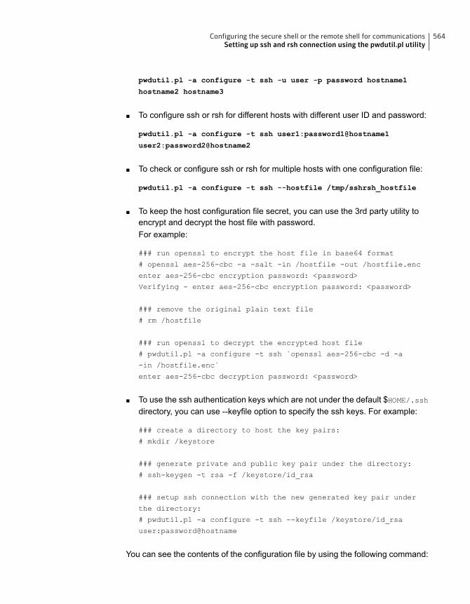
pwdutil.pl -a configure -t ssh -u user -p password hostname1
hostname2 hostname3
■ To configure ssh or rsh for different hosts with different user ID and password:
pwdutil.pl -a configure -t ssh user1:password1@hostname1
user2:password2@hostname2
■ To check or configure ssh or rsh for multiple hosts with one configuration file:
pwdutil.pl -a configure -t ssh --hostfile /tmp/sshrsh_hostfile
■ To keep the host configuration file secret, you can use the 3rd party utility toencrypt and decrypt the host file with password.For example:
### run openssl to encrypt the host file in base64 format
# openssl aes-256-cbc -a -salt -in /hostfile -out /hostfile.enc
enter aes-256-cbc encryption password: <password>
Verifying - enter aes-256-cbc encryption password: <password>
### remove the original plain text file
# rm /hostfile
### run openssl to decrypt the encrypted host file
# pwdutil.pl -a configure -t ssh `openssl aes-256-cbc -d -a
-in /hostfile.enc`
enter aes-256-cbc decryption password: <password>
■ To use the ssh authentication keys which are not under the default $HOME/.sshdirectory, you can use --keyfile option to specify the ssh keys. For example:
### create a directory to host the key pairs:
# mkdir /keystore
### generate private and public key pair under the directory:
# ssh-keygen -t rsa -f /keystore/id_rsa
### setup ssh connection with the new generated key pair under
the directory:
# pwdutil.pl -a configure -t ssh --keyfile /keystore/id_rsa
user:password@hostname
You can see the contents of the configuration file by using the following command:
564Configuring the secure shell or the remote shell for communicationsSetting up ssh and rsh connection using the pwdutil.pl utility
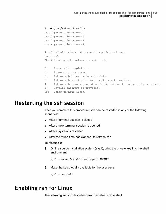
# cat /tmp/sshrsh_hostfile
user1:password1@hostname1
user2:password2@hostname2
user3:password3@hostname3
user4:password4@hostname4
# all default: check ssh connection with local user
hostname5
The following exit values are returned:
0 Successful completion.
1 Command syntax error.
2 Ssh or rsh binaries do not exist.
3 Ssh or rsh service is down on the remote machine.
4 Ssh or rsh command execution is denied due to password is required.
5 Invalid password is provided.
255 Other unknown error.
Restarting the ssh sessionAfter you complete this procedure, ssh can be restarted in any of the followingscenarios:
■ After a terminal session is closed
■ After a new terminal session is opened
■ After a system is restarted
■ After too much time has elapsed, to refresh ssh
To restart ssh
1 On the source installation system (sys1), bring the private key into the shellenvironment.
sys1 # exec /usr/bin/ssh-agent $SHELL
2 Make the key globally available for the user root
sys1 # ssh-add
Enabling rsh for LinuxThe following section describes how to enable remote shell.
565Configuring the secure shell or the remote shell for communicationsRestarting the ssh session
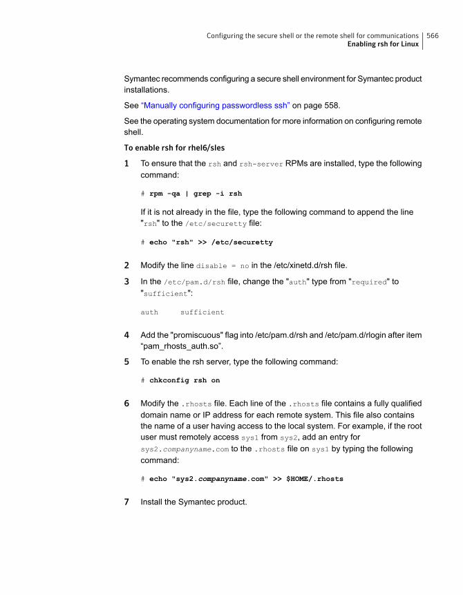
Symantec recommends configuring a secure shell environment for Symantec productinstallations.
See “Manually configuring passwordless ssh” on page 558.
See the operating system documentation for more information on configuring remoteshell.
To enable rsh for rhel6/sles
1 To ensure that the rsh and rsh-server RPMs are installed, type the followingcommand:
# rpm -qa | grep -i rsh
If it is not already in the file, type the following command to append the line"rsh" to the /etc/securetty file:
# echo "rsh" >> /etc/securetty
2 Modify the line disable = no in the /etc/xinetd.d/rsh file.
3 In the /etc/pam.d/rsh file, change the "auth" type from "required" to"sufficient":
auth sufficient
4 Add the "promiscuous" flag into /etc/pam.d/rsh and /etc/pam.d/rlogin after item“pam_rhosts_auth.so”.
5 To enable the rsh server, type the following command:
# chkconfig rsh on
6 Modify the .rhosts file. Each line of the .rhosts file contains a fully qualifieddomain name or IP address for each remote system. This file also containsthe name of a user having access to the local system. For example, if the rootuser must remotely access sys1 from sys2, add an entry forsys2.companyname.com to the .rhosts file on sys1 by typing the followingcommand:
# echo "sys2.companyname.com" >> $HOME/.rhosts
7 Install the Symantec product.
566Configuring the secure shell or the remote shell for communicationsEnabling rsh for Linux
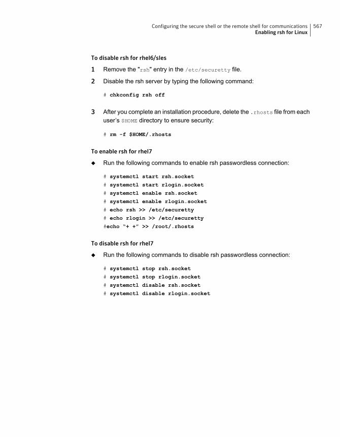
To disable rsh for rhel6/sles
1 Remove the "rsh" entry in the /etc/securetty file.
2 Disable the rsh server by typing the following command:
# chkconfig rsh off
3 After you complete an installation procedure, delete the .rhosts file from eachuser’s $HOME directory to ensure security:
# rm -f $HOME/.rhosts
To enable rsh for rhel7
◆ Run the following commands to enable rsh passwordless connection:
# systemctl start rsh.socket
# systemctl start rlogin.socket
# systemctl enable rsh.socket
# systemctl enable rlogin.socket
# echo rsh >> /etc/securetty
# echo rlogin >> /etc/securetty
#echo “+ +” >> /root/.rhosts
To disable rsh for rhel7
◆ Run the following commands to disable rsh passwordless connection:
# systemctl stop rsh.socket
# systemctl stop rlogin.socket
# systemctl disable rsh.socket
# systemctl disable rlogin.socket
567Configuring the secure shell or the remote shell for communicationsEnabling rsh for Linux
Troubleshooting VCSinstallation
This appendix includes the following topics:
■ What to do if you see a licensing reminder
■ Restarting the installer after a failed connection
■ Starting and stopping processes for the Symantec products
■ Installer cannot create UUID for the cluster
■ LLT startup script displays errors
■ The vxfentsthdw utility fails when SCSI TEST UNIT READY command fails
■ Issues during fencing startup on VCS cluster nodes set up for server-basedfencing
What to do if you see a licensing reminderIn this release, you can install without a license key. In order to comply with theEnd User License Agreement, you must either install a license key or make thehost managed by a Management Server. If you do not comply with these termswithin 60 days, the following warning messages result:
WARNING V-365-1-1 This host is not entitled to run Symantec Storage
Foundation/Symantec Cluster Server.As set forth in the End User
License Agreement (EULA) you must complete one of the two options
set forth below. To comply with this condition of the EULA and
stop logging of this message, you have <nn> days to either:
- make this host managed by a Management Server (see
IAppendix
http://go.symantec.com/sfhakeyless for details and free download),
or
- add a valid license key matching the functionality in use on this host
using the command 'vxlicinst' and validate using the command
'vxkeyless set NONE'.
To comply with the terms of the EULA, and remove these messages, you must doone of the following within 60 days:
■ Install a valid license key corresponding to the functionality in use on the host.After you install the license key, you must validate the license key using thefollowing command:
# /opt/VRTS/bin/vxlicrep
■ Continue with keyless licensing by managing the server or cluster with amanagement server.For more information about keyless licensing, see the following URL:http://go.symantec.com/sfhakeyless
Restarting the installer after a failed connectionIf an installation is killed because of a failed connection, you can restart the installerto resume the installation. The installer detects the existing installation. The installerprompts you whether you want to resume the installation. If you resume theinstallation, the installation proceeds from the point where the installation failed.
Starting and stopping processes for the Symantecproducts
After the installation and configuration is complete, the Symantec product installerstarts the processes that the installed products use. You can use the product installerto stop or start the processes, if required.
569Troubleshooting VCS installationRestarting the installer after a failed connection
To stop the processes
◆ Use the -stop option to stop the product installation script.
For example, to stop the product's processes, enter the following command:
# ./installer -stop
or
# /opt/VRTS/install/installvcs<version> -stop
Where <version> is the specific release version.
See “About the script-based installer” on page 49.
To start the processes
◆ Use the -start option to start the product installation script.
For example, to start the product's processes, enter the following command:
# ./installer -start
or
# /opt/VRTS/install/installvcs<version> -start
Where <version> is the specific release version.
See “About the script-based installer” on page 49.
Installer cannot create UUID for the clusterThe installer displays the following error message if the installer cannot find theuuidconfig.pl script before it configures the UUID for the cluster:
Couldn't find uuidconfig.pl for uuid configuration,
please create uuid manually before start vcs
You may see the error message during VCS configuration, upgrade, or when youadd a node to the cluster using the installer.
Workaround: To start VCS, you must run the uuidconfig.pl script manually toconfigure the UUID on each cluster node.
570Troubleshooting VCS installationInstaller cannot create UUID for the cluster

To configure the cluster UUID when you create a cluster manually
◆ On one node in the cluster, perform the following command to populate thecluster UUID on each node in the cluster.
# /opt/VRTSvcs/bin/uuidconfig.pl -clus -configure nodeA
nodeB ... nodeN
Where nodeA, nodeB, through nodeN are the names of the cluster nodes.
LLT startup script displays errorsIf more than one system on the network has the same clusterid-nodeid pair andthe same Ethernet sap/UDP port, then the LLT startup script displays error messagessimilar to the following:
LLT lltconfig ERROR V-14-2-15238 node 1 already exists
in cluster 8383 and has the address - 00:18:8B:E4:DE:27
LLT lltconfig ERROR V-14-2-15241 LLT not configured,
use -o to override this warning
LLT lltconfig ERROR V-14-2-15664 LLT could not
configure any link
LLT lltconfig ERROR V-14-2-15245 cluster id 1 is
already being used by nid 0 and has the
address - 00:04:23:AC:24:2D
LLT lltconfig ERROR V-14-2-15664 LLT could not
configure any link
Recommended action: Ensure that all systems on the network have uniqueclusterid-nodeid pair. You can use the lltdump -f device -D command to getthe list of unique clusterid-nodeid pairs connected to the network. This utility isavailable only for LLT-over-ethernet.
The vxfentsthdw utility fails when SCSI TEST UNITREADY command fails
While running the vxfentsthdw utility, you may see a message that resembles asfollows:
Issuing SCSI TEST UNIT READY to disk reserved by other node
FAILED.
Contact the storage provider to have the hardware configuration
fixed.
571Troubleshooting VCS installationLLT startup script displays errors
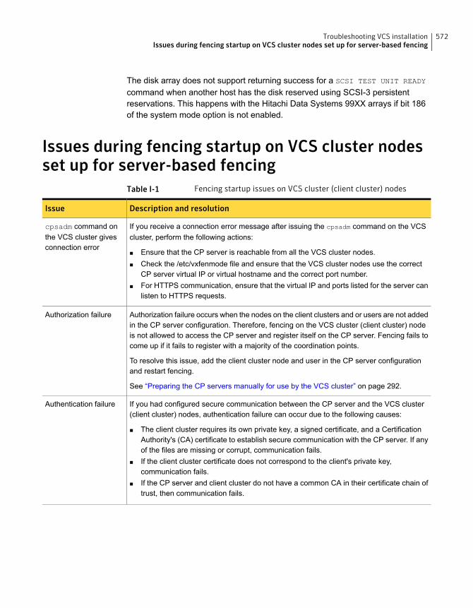
The disk array does not support returning success for a SCSI TEST UNIT READY
command when another host has the disk reserved using SCSI-3 persistentreservations. This happens with the Hitachi Data Systems 99XX arrays if bit 186of the system mode option is not enabled.
Issues during fencing startup on VCS cluster nodesset up for server-based fencing
Table I-1 Fencing startup issues on VCS cluster (client cluster) nodes
Description and resolutionIssue
If you receive a connection error message after issuing the cpsadm command on the VCScluster, perform the following actions:
■ Ensure that the CP server is reachable from all the VCS cluster nodes.■ Check the /etc/vxfenmode file and ensure that the VCS cluster nodes use the correct
CP server virtual IP or virtual hostname and the correct port number.■ For HTTPS communication, ensure that the virtual IP and ports listed for the server can
listen to HTTPS requests.
cpsadm command onthe VCS cluster givesconnection error
Authorization failure occurs when the nodes on the client clusters and or users are not addedin the CP server configuration. Therefore, fencing on the VCS cluster (client cluster) nodeis not allowed to access the CP server and register itself on the CP server. Fencing fails tocome up if it fails to register with a majority of the coordination points.
To resolve this issue, add the client cluster node and user in the CP server configurationand restart fencing.
See “Preparing the CP servers manually for use by the VCS cluster” on page 292.
Authorization failure
If you had configured secure communication between the CP server and the VCS cluster(client cluster) nodes, authentication failure can occur due to the following causes:
■ The client cluster requires its own private key, a signed certificate, and a CertificationAuthority's (CA) certificate to establish secure communication with the CP server. If anyof the files are missing or corrupt, communication fails.
■ If the client cluster certificate does not correspond to the client's private key,communication fails.
■ If the CP server and client cluster do not have a common CA in their certificate chain oftrust, then communication fails.
Authentication failure
572Troubleshooting VCS installationIssues during fencing startup on VCS cluster nodes set up for server-based fencing
Sample VCS cluster setupdiagrams for CPserver-based I/O fencing
This appendix includes the following topics:
■ Configuration diagrams for setting up server-based I/O fencing
Configuration diagrams for setting up server-basedI/O fencing
The following CP server configuration diagrams can be used as guides when settingup CP server within your configuration:
■ Two unique client clusters that are served by 3 CP servers:See Figure J-1 on page 574.
■ Client cluster that is served by highly available CP server and 2 SCSI-3 disks:
■ Two node campus cluster that is served be remote CP server and 2 SCSI-3disks:
■ Multiple client clusters that are served by highly available CP server and 2SCSI-3 disks:
Two unique client clusters served by 3 CP serversFigure J-1 displays a configuration where two unique client clusters are being servedby 3 CP servers (coordination points). Each client cluster has its own unique userID (UUID1 and UUID2).
JAppendix
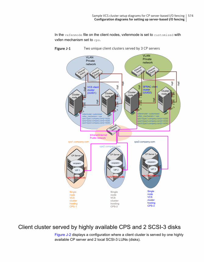
In the vxfenmode file on the client nodes, vxfenmode is set to customized withvxfen mechanism set to cps.
Figure J-1 Two unique client clusters served by 3 CP servers
NIC
1
Cluster -1node 1
NIC
2
NIC
1
Cluster-1node 2
NIC
2
Ethernet
SwitchEthernet
Switch
NIC
1
Cluster -2node 1
NIC
2
NIC
1
Cluster-2node 2
NIC
2
Ethernet
SwitchEthernet
Switch
NIC
CP Server 1
Ethernet
Switch
Intranet/InternetPublic network
CP Server 2
NIC
CP Server 3
NIC
NIC 3 NIC 3 NIC 3 NIC 3
VCS clientcluster(UUID1)
SFRAC clientcluster(UUID2)
SinglenodeVCSclusterhostingCPS-1
SinglenodeVCSclusterhostingCPS-2
SinglenodeVCSclusterhostingCPS-3
/etc/VRTScps/db/etc/VRTScps/db/etc/VRTScps/db
vxcpserv
VIP 1
vxcpserv
VIP 2
vxcpserv
VIP 3
HBAHBA HBA
HBA
Gig
E
Gig
E
Gig
E
Gig
E Gig
E
Gig
E
Gig
E
Gig
E
VLANPrivatenetwork
VLANPrivatenetwork
cps1.company.com
cps2.company.com
cps3.company.com
vxfenmode= customizedvxfen_mechanism = cpscps1=[cps1.company.com]=14250cps2=[cps2.company.com]=14250cps3=[cps3.company.com]=14250
vxfenmode= customizedvxfen_mechanism = cpscps1=[cps1.company.com]=14250cps2=[cps2.company.com]=14250cps3=[cps3.company.com]=14250
Client cluster served by highly available CPS and 2 SCSI-3 disksFigure J-2 displays a configuration where a client cluster is served by one highlyavailable CP server and 2 local SCSI-3 LUNs (disks).
574Sample VCS cluster setup diagrams for CP server-based I/O fencingConfiguration diagrams for setting up server-based I/O fencing
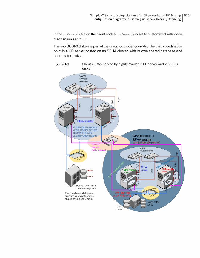
In the vxfenmode file on the client nodes, vxfenmode is set to customized with vxfenmechanism set to cps.
The two SCSI-3 disks are part of the disk group vxfencoorddg. The third coordinationpoint is a CP server hosted on an SFHA cluster, with its own shared database andcoordinator disks.
Figure J-2 Client cluster served by highly available CP server and 2 SCSI-3disks
SAN
FC Switch
CPS database/etc/VRTScps/db
NIC
1
Cluster -1node 1
NIC
2
NIC
1
Cluster-1node 2
NIC
2Ethernet
SwitchEthernet
Switch
VLANPrivatenetwork
Ethernet
Switch
Intranet/InternetPublic network
NIC 3 NIC 3Client cluster
NIC
1
CPS-Primarynode
NIC
2
NIC
1
CPS-standbynode
NIC
2
Ethernet
Switch Ethernet
Switch
VLANPrivate network
NIC 3NIC 3
SFHAcluster
VIPvxcpserv
vxcp
serv
VIP
DataLUNs
CoordinatorLUNs
SAN
FC Switch
SCSI-3 LUNs as 2coordination points
disk1
disk2
CPS hosted onSFHA clustercp1=[VIP]:14250(port no.)
HBA HBA
HBAHBA
Gig
E
Gig
E
Gig
E Gig
E
Gig
E
Gig
E
Gig
EG
igE
cps1.company.com
cps2.company.com
vxfenmode=customizedvxfen_mechanism=cpscps1=[VIP]:14250vxfendg=vxfencoorddg
The coordinator disk groupspecified in /etc/vxfenmodeshould have these 2 disks.
575Sample VCS cluster setup diagrams for CP server-based I/O fencingConfiguration diagrams for setting up server-based I/O fencing
Two node campus cluster served by remote CP server and 2 SCSI-3disks
Figure J-3 displays a configuration where a two node campus cluster is being servedby one remote CP server and 2 local SCSI-3 LUN (disks).
In the vxfenmode file on the client nodes, vxfenmode is set to customized withvxfen mechanism set to cps.
The two SCSI-3 disks (one from each site) are part of disk group vxfencoorddg.The third coordination point is a CP server on a single node VCS cluster.
576Sample VCS cluster setup diagrams for CP server-based I/O fencingConfiguration diagrams for setting up server-based I/O fencing
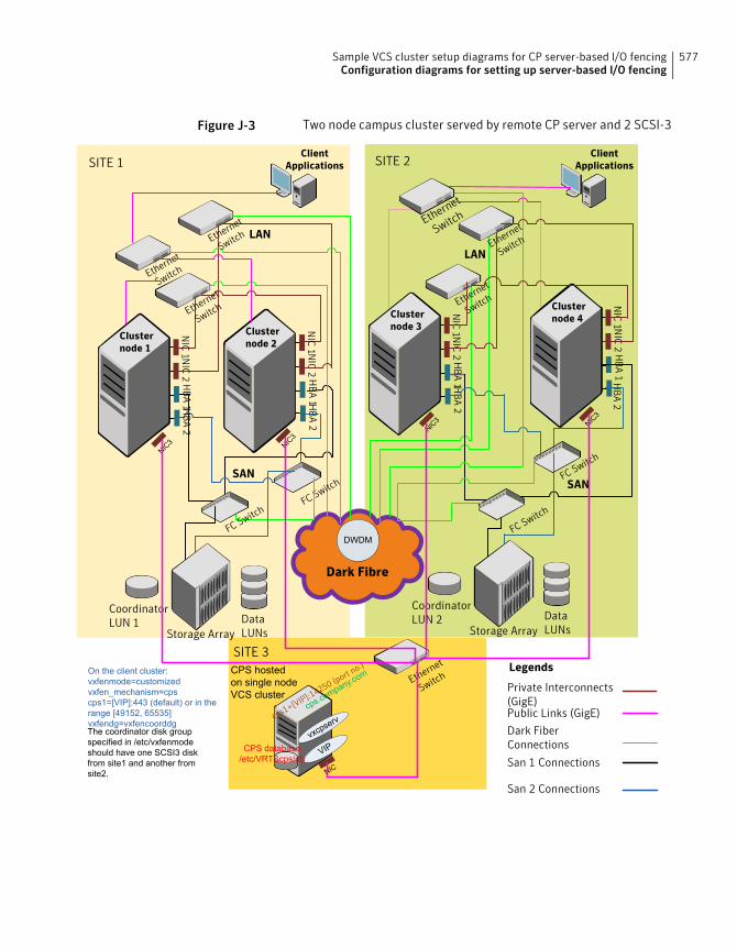
Figure J-3 Two node campus cluster served by remote CP server and 2 SCSI-3
LAN
LAN
Dark Fibre
SITE 1 SITE 2
SITE 3
NIC
1 NIC
2H
BA
2H
BA
1
Clusternode 1
NIC
1 NIC
2H
BA
2H
BA
1
Clusternode 2
NIC
1 NIC
2H
BA
2H
BA
1
Clusternode 3
NIC
1 NIC
2H
BA
2H
BA
1
Clusternode 4
ClientApplications
ClientApplications
Ethernet
Switch
Ethernet
Switch
Ethernet
Switch
Ethernet
Switch
Ethernet
Switch
Ethernet
Switch
FC SwitchFC Switch
FC Switch
FC Switch
CoordinatorLUN 1 Data
LUNsStorage Array
CoordinatorLUN 2 Data
LUNsStorage Array
DWDM
Private Interconnects(GigE)
San 2 Connections
Legends
Dark FiberConnections
San 1 Connections
Public Links (GigE)
SANSAN
CPS hostedon single nodeVCS cluster
NIC
VIPvxcpserv
CPS database/etc/VRTScps/db
cps.company.com Ethernet
Switch
NIC3 NIC
3
cps1=[VIP]:14250 (port no.)
NIC3 NIC
3
The coordinator disk groupspecified in /etc/vxfenmodeshould have one SCSI3 diskfrom site1 and another fromsite2.
On the client cluster:vxfenmode=customizedvxfen_mechanism=cpscps1=[VIP]:443 (default) or in therange [49152, 65535]vxfendg=vxfencoorddg
577Sample VCS cluster setup diagrams for CP server-based I/O fencingConfiguration diagrams for setting up server-based I/O fencing

Multiple client clusters served by highly available CP server and 2SCSI-3 disks
Figure J-4 displays a configuration where multiple client clusters are being servedby one highly available CP server and 2 local SCSI-3 LUNS (disks).
In the vxfenmode file on the client nodes, vxfenmode is set to customized withvxfen mechanism set to cps.
The two SCSI-3 disks are are part of the disk group vxfencoorddg. The thirdcoordination point is a CP server, hosted on an SFHA cluster, with its own shareddatabase and coordinator disks.
578Sample VCS cluster setup diagrams for CP server-based I/O fencingConfiguration diagrams for setting up server-based I/O fencing
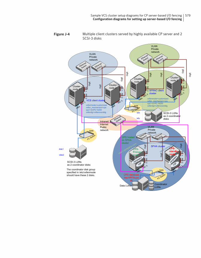
Figure J-4 Multiple client clusters served by highly available CP server and 2SCSI-3 disks
CPS database/etc/VRTScps/
db
NIC
1
Cluster -1node 1
NIC
2
NIC
1
Cluster-1node 2
NIC
2
Ethernet
SwitchEthernet
Switch
VLANPrivatenetwork
Ethernet
SwitchIntranet/InternetPublicnetwork
NIC 3 NIC 3VCS client cluster
NIC
1
CPS-Primarynode
NIC
2
NIC
1
CPS-standbynode
NIC
2
Ethernet
Switch Ethernet
Switch
VLANPrivatenetwork
NIC 3NIC 3
SFHA cluster
VIPvxcpserv
vxcp
serv
VIP
Data LUNs CoordinatorLUNs
SAN
FC Switch
SCSI-3 LUNsas 2 coordinator disks
SAN
FC Switch
disk1
disk2
NIC
1
Cluster -2node 1
NIC
2
NIC
1
Cluster-2node 2
NIC
2
Ethernet
SwitchEthernet
Switch
VLANPrivatenetwork
NIC 3 NIC 3SFRAC clientcluster
SAN
FC Switch
sdx
sdy
CPS hostedon SFHAcluster
HBA HBA
HBAHBA
HBAHBA
SCSI-3 LUNsas 2 coordinatordisks
Gig
E
Gig
E
Gig
E
Gig
E
Gig
E
Gig
E
Gig
EGig
E
Gig
E
Gig
E
Gig
E
cps1.company.com
cps2.company.com
vxfenmode=customizedvxfen_mechanism=cpscps1=[VIP]:14250vxfendg=vxfencoorddg
vxfenmode=customizedvxfen_mechanism=cpscps1=[VIP]:14250vxfendg=vxfencoorddg
The coordinator disk groupspecified in /etc/vxfenmodeshould have these 2 disks.
579Sample VCS cluster setup diagrams for CP server-based I/O fencingConfiguration diagrams for setting up server-based I/O fencing
Compatibility issues wheninstalling Symantec ClusterServer with other products
This appendix includes the following topics:
■ Installing, uninstalling, or upgrading Storage Foundation products when otherSymantec products are present
■ Installing, uninstalling, or upgrading Storage Foundation products when VOMis already present
■ Installing, uninstalling, or upgrading Storage Foundation products whenApplicationHA is already present
■ Installing, uninstalling, or upgrading Storage Foundation products whenNetBackup is already present
Installing, uninstalling, or upgrading StorageFoundation products when other Symantec productsare present
Installing Storage Foundation when other Symantec products are installed cancreate compatibility issues. For example, installing Storage Foundation productswhen VOM, ApplicationHA, and NetBackup are present on the systems.
KAppendix
Installing, uninstalling, or upgrading StorageFoundation products when VOM is already present
If you plan to install or upgrade Storage Foundation products on systems whereVOM has already been installed, be aware of the following compatibility issues:
■ When you install or upgrade Storage Foundation products where VOM CentralServer is present, the installer skips the VRTSsfmh upgrade and leaves theVOM Central Server and Managed Host RPMs as is.
■ When uninstalling Storage Foundation products where VOM Central Server ispresent, the installer does not uninstall VRTSsfmh.
■ When you install or upgrade Storage Foundation products where VOM ManagedHost is present, the installer gives warning messages that it will upgradeVRTSsfmh.
Installing, uninstalling, or upgrading StorageFoundation products when ApplicationHA is alreadypresent
If you plan to install or upgrade Storage Foundation on systems where ApplicationHAhas already been installed, be aware of the following compatibility issues:
■ When you install or upgrade Storage Foundation products where ApplicationHAis present, the installer does not consider VCS as an installed product eventhough it uses the bundled VRTSvcs RPM.
■ When you install or upgrade Storage Foundation products where ApplicationHAis present, the installer does not allow the installation or upgrade for productsthat use VCS. The following products cannot be installed or upgrade: VCS,SFHA, SFCFS, SFCFSHA, SFRAC, SFCFSRAC or SFSYBASECE.
■ When you install or upgrade Storage Foundation products where ApplicationHAis present, the installer allows the installation or upgrade of VM, FS, SF, or DMP.
■ When you uninstall Storage Foundation products where ApplicationHA is present,the installer does not uninstall VRTSsfmh.
581Compatibility issues when installing Symantec Cluster Server with other productsInstalling, uninstalling, or upgrading Storage Foundation products when VOM is already present
Installing, uninstalling, or upgrading StorageFoundation products when NetBackup is alreadypresent
If you plan to install or upgrade Storage Foundation on systems where NetBackuphas already been installed, be aware of the following compatibility issues:
■ When you install or upgrade Storage Foundation products where NetBackup ispresent, the installer does not uninstall VRTSpbx and VRTSicsco. It does notupgrade VRTSat.
■ When you uninstall Storage Foundation products where NetBackup is present,the installer does not uninstall VRTSpbx, VRTSicsco, and VRTSat.
582Compatibility issues when installing Symantec Cluster Server with other productsInstalling, uninstalling, or upgrading Storage Foundation products when NetBackup is already present
Upgrading the Stewardprocess
This appendix includes the following topics:
■ Upgrading the Steward process
Upgrading the Steward processThe Steward process can be configured in both secure and non-secure mode. Thefollowing procedures provide the steps to upgrade the Steward process.
Upgrading Steward configured in secure mode from 6.1 to 6.2To upgrade Steward configured in secure mode:
1 Log on to the Steward system as a root user.
2 Stop the Steward process.
# steward -stop -secure
3 Upgrade the VRTSvcs and VRTSperl RPMs using:
# rpm -Uvh
4 Start the Steward process.
# steward -start -secure
LAppendix
Upgrading Steward configured in non-secure mode from 6.1to 6.2To upgrade Steward configured in non-secure mode:
1 Log on to the Steward system as a root user.
2 Stop the Steward process.
# steward -stop
3 Copy and replace the Steward binary from a node in the VCS 6.2 cluster tothe Steward system. The file resides in the /opt/VRTSvcs/bin/ directory.Make sure that the source from where you copy the binary is also running thesame version of Linux as the destination system.
4 Start the Steward process.
# steward -start
Refer to About the Steward process: Split-brain in two-cluster global clusters in theSymantec Cluster Server Administrator's Guide for more information.
584Upgrading the Steward processUpgrading the Steward process
Symbols/etc/llttab
LLT directives 268
Aabout
Deployment Server 318global clusters 27installation and configuration methods 55SORT 30Symantec product licensing 61Veritas Operations Manager 29web-based installer 53
About RDMARDMA over Converged Ethernet or InfiniBand
networksclustering environment 536
addingClusterService group 285system to VCS cluster 283users 149
adding nodeto a one-node cluster 437
attributesUseFence 289, 312
Bbefore using
web-based installer 188Blade server considerations 76bundled agents
types.cf file 270
Ccables
cross-over Ethernet 449checking product versions 45cluster
creating a single-node clusterinstaller 520
cluster (continued)creating a single-node cluster (continued)
manual 521four-node configuration 24removing a node from 463verifying operation 428
cluster configuration wizardabout 276considerations 277launching 278launching from a browser window 278launching from vSphere Client 278
Cluster Manager 29installing Java Console 417
ClusterService groupadding manually 285
cold startrunning VCS 26
commandsgabconfig 270, 427hastart 460hastatus 428hastop 482hasys 429lltconfig 501lltstat 425vxdisksetup (initializing disks) 158vxlicinst 156, 251vxlicrep 155, 253
communication channels 25communication disk 25configuration files
types.cf 270configuring
GAB 270hardware 38LLT
manual 267private network 67rsh 70ssh 70switches 67
Index

configuring VCSadding users 149event notification 150–151global clusters 153required information 79script-based installer 132starting 132
controllersprivate Ethernet 67
coordinator disksDMP devices 34for I/O fencing 34setting up 287
creatingInstall Templates 343
Ddata disks
for I/O fencing 34defining
Install Bundles 338demo key 253deploying
Symantec product updates to yourenvironment 335
Symantec releases 345deploying using
Install Bundles 345deploying using Install Templates
Install Templates 345deployment preferences
setting 324Deployment Server
about 318downloading the most recent release information
from the SORT site 326installing 320loading release information and patches on
to 327overview 319proxy server 348setting up 321specifying a non-default repository location 326
directivesLLT 268
disablingexternal network connection attempts 47
disk spacedirectories 38
disk space (continued)required 38
disk space requirements 39disks
adding and initializing 158coordinator 287testing with vxfentsthdw 163verifying node access 165
documentationaccessing 415
downloading maintenance releases and patches 45downloading the most recent release information
by running the Deployment Server from a systemwith Internet access 326
Eeeprom
parameters 67Ethernet controllers 67, 449existing coordination points
order 210
Ffibre channel 38
GGAB
description 25manual configuration 270port membership information 427starting 275verifying 427
gabconfig command 270, 427-a (verifying GAB) 427
gabtab filecreating 270verifying after installation 501
global clusters 27configuration 153
Hhardware
configuration 24configuring network and storage 38
hastart 460hastatus -summary command 428hastop command 482hasys -display command 429
586Index

hubs 67independent 449
II/O fencing
checking disks 163setting up 286shared storage 163
I/O fencing requirementsnon-SCSI-3 44
Install Bundlesdefining 338deploying using the Deployment Server 345integration options 359
Install Templatescreating 343deploying using Install Templates 345
installationRed Hat Satellite server 263
installerabout the script-based installer 49
installer patchesobtaining either manually or automatically 46
InstallingVCS with the web-based installer 190web-based installer 190
installingmanual 247post 154required disk space 38simulator 420Symantec product license keys 63the Deployment Server 320using Kickstart 254using response files 214using yum 258
installing VCSrequired information 79
installvcsoptions 52
installvcs promptsb 52n 52y 52
JJava Console 29
installing 417
Java Console (continued)installing on UNIX 417
Kkernel.hung_task_panic tunable 75kernel.panic tunable
setting 74keyless licensing
setting or changing the product level 251Kickstart
installing 254sample configuration file 256
Llicense keys
adding with vxlicinst 156, 251obtaining 62replacing demo key 156, 253
licensesinformation about 155showing information 253
licensinginstalling Symantec product license keys 63setting or changing the product level for keyless
licensing 251limitatoins
online upgrade 367links
private network 501LLT
description 25directives 268interconnects 76manual configuration 267starting 275verifying 425
LLT directiveslink 268link-lowpri 268set-cluster 268set-node 268
LLT over RDMAconfigure 538faster interconnects 537supported use cases 538
lltconfig command 501llthosts file
verifying after installation 501
587Index
lltstat command 425llttab file
verifying after installation 501
MMAC addresses 67main.cf file
contents after installation 506main.cf files 512MANPATH variable
setting 74media speed 76
optimizing 75membership information 427mounting
software disc 76
Nnetwork partition
preexisting 26protecting against 24
Network partitionsprotecting against 25
network switches 67NFS 23non-SCSI-3 fencing
manual configuration 306setting up 306
non-SCSI-3 I/O fencingrequirements 44
non-SCSI3 fencingsetting up 180using installvcs 180
Oobtaining
installer patches either automatically ormanually 46
security exception on Mozilla Firefox 189optimizing
media speed 75overview
Deployment Server 319VCS 23
Pparameters
eeprom 67
PATH variablesetting 74VCS commands 424
persistent reservationsSCSI-3 70
phased 372phased upgrade 372, 374
example 373port a
membership 427port h
membership 427port membership information 427preinstallation check
web-based installer 190prerequisites
uninstalling 473private network
configuring 67proxy server
connecting the Deployment Server 348
RRAM
installation requirement 38RDMA
Configure drivers 541, 544Configure interfaces 546Driver installation 540manually configure LLT 549OpenSM service 545supported hardware 539troubleshoot 555Tune system performance 547Verify LLT configuration 553
Red Hat Satellite serverinstalling 263
release imagesviewing or downloading available 328
release information and patchesloading using the Deployment Server 327
release notes 37releases
finding out which releases you have, and whichupgrades or updates you may need 336
removing a system from a cluster 463repository images
viewing and removing repository images storedin your repository 333
588Index
requirementsEthernet controllers 38fibre channel 38hardware 38RAM Ethernet controllers 38SCSI host bus adapter 38
response files 54installation 214rolling upgrade 393syntax 54uninstalling 479upgrading 390
rolling upgrade 401using response files 393using the script-based installer 401versions 398
rsh 133configuration 70
Sscript-based installer
about 49online upgrade 368VCS configuration overview 132
SCSI host bus adapter 38SCSI-3
persistent reservations 70SCSI-3 persistent reservations
verifying 286seeding 26
automatic 26manual 26
settingdeployment preferences 324kernel.panic tunable 74MANPATH variable 74PATH variable 74
setting upDeployment Server 321
simulataneous install or upgrade 359simulator
installing 420single-node cluster
adding a node to 437single-system cluster
creating 520–521modifying startup files 522
SMTP email notification 150SNMP trap notification 151
specifyingnon-default repository location 326
ssh 133configuration 70
startingweb-based installer 189
starting configurationinstallvcs program 133product installer 133
starting VCS after manual upgrade 274starting VCS after rpm -i 275storage
fully shared vs. distributed 24shared 24
supported operating systems 39switches 67Symantec product license keys
installing 63Symantec product updates
deploying to your environment 335Symantec products
starting process 569stopping process 569
Symantec releasesdeploying a specific release 345
system state attribute value 428
Ttypes.cf 270
bundled agents 270types.cf file 270
Uuninstalling
prerequisites 473using response files 479using the web-based installer 475
upgradephased 372, 374supported upgrade paths 351
upgrades or updatesfinding out which releases you have 336
upgradingphased 372rolling 401using response files 390using the web-based installer 364
589Index

upgrading onlineusing script-based installer 368using the web-based installer 369
upgrading Stewardin secure mode 583in-non-secure mode 583
Vvariables
MANPATH 74PATH 74
VCSbasics 23command directory path variable 424configuration files
main.cf 505configuring 132coordinator disks 287documentation 415manually installing 247notifications 27replicated states on each system 24starting 274–275
VCS features 27VCS installation
preinstallation information 38verifying
cluster operations 424GAB operations 424LLT operations 424
VCS notificationsSMTP notification 27SNMP notification 27
verifyingNIC configuration 154
viewing and removing repository imagesstored in your repository 333
viewing or downloadingavailable release images 328
vxdisksetup command 158vxlicinst command 156, 251vxlicrep command 155, 253
Wweb-based installer 190
about 53before using 188installation 190
web-based installer (continued)online upgrade 369preinstallation check 190starting 189uninstalling 475upgrading 364
Yyum
installing 258
590Index