syllabus for hites’11 class project - utkweb.eecs.utk.edu/~markdean/syllabus for hites11.pdf ·...
TRANSCRIPT

Syllabus for Hites’11 Class Project
Introductions: - Hobbies, Interest and Goals
- Overview of what will be covered
o Handout kits and cover functions to be programmed
- Demonstration of project (show video from the 2015 HITES’11 team)
o File -
HITES11TeamDemo.
MP4
1.0 Overview of Arduino: (note: leverages ArduinoClassroom.com – Arduino 101)
The official Arduino website is located at: www.arduino.cc
What is an Arduino? http://www.arduino.cc/en/Guide/Introduction
Arduino is a tool (microcontroller) for making computers that can sense and control more of
the physical world than your desktop computer. It's an open-source physical computing
platform based on a simple microcontroller board, and a development environment for writing
software for the board.
Arduino can be used to develop interactive objects, taking inputs from a variety of switches
and/or sensors, and controlling a variety of lights, motors, and other physical outputs. Arduino
projects can be stand-alone, or they can communicate with software running on your computer
(e.g. Flash, Processing, MaxMSP.) The boards can be assembled by hand or purchased
preassembled; the open-source IDE can be downloaded for free.
Arduino 101 – http://www.arduinoclassroom.com/index.php/arduino-101/chapter-1
What is a Microcontroller?
What can you do with a Microcontroller? Examples
Downloading Software Environment –
http://www.arduino.cc/en/Main/Software
Installing Additional Cores (required for Arduino Due) –
https://www.arduino.cc/en/Guide/Cores
Copy Arduino sketches and libraries (provided via USB Thumb Drive in “Arduino” folder)
to “Arduino” folder on system (usually established in “documents” directory). This is
required to make sure the “libraries” folder is accessible (in the expected directory) by
the Arduino IDE.

- More details for Arduino Due - http://www.arduino.cc/en/Guide/ArduinoDue
Fig. 1 - The Arduino Uno R3
Fig. 2 - The Arduino Due has two USB ports available.
Foundations for getting started and understanding the Arduino -
http://www.arduino.cc/en/Tutorial/Foundations
- Basics Sketch - http://www.arduino.cc/en/Tutorial/Sketch
- Microcontrollers

o Digital Pins: How the pins work and what it means for them to be configured
as inputs or outputs.
o Analog Input Pins: Details about the analog-to-digital conversion and other
uses of the pins.
o PWM: How the analogWrite() function simulates an analog output using
pulse-width modulation.
- Programming Technique
o Variables How to define and use variables.
o Functions: How to define and use functions.
For Reference:
Other Arduino web resources:
http://www.arduinoclassroom.com/index.php/arduino-101 - a logical progression for the
presentation of information on Arduino. A series of articles and websites organized as a
sensible learning sequence and presents labs with tested examples using a hardware projects
kit. Having this structure helps you move quickly thorough what you need to know and provides
you with a base of knowledge and skills that you use to pursue more advanced projects using
what you find on the Internet. So let's get started!
http://www.arduino.cc/en/Tutorial/HomePage - Example codes and libraries.
http://www.arduino.cc/en/Reference/HomePage – Language References
Vendors with components and projects support the Arduino enthusiast –
https://www.sparkfun.com/ - Sparkfun
https://www.adafruit.com/ - Adafruit
http://www.robotshop.com/en/ - Robot Shop
http://www.dfrobot.com/ - DF Robot

2.0 Class Syllabus and Project Overview:
- What is a Microcontroller and what can they be used for?
- Functionality of Arduino Due - http://www.arduino.cc/en/Main/ArduinoBoardDue
- Functionality of Multi-Function Board - http://www.getmicros.net/arduino-multi-
function-shield.php
Features:
o 4 digit 7-segment LED display module driven by two serial 74HC595’s
o 4 LED’s
o 10K potentiometer
o 3 x push buttons
o Piezo buzzer
o DS18B20 temperature sensor interface (not included)
o Infrared receiver interface (not covered in this exercise)
o Serial interface header for connection to serial modules
Scope of Activities (Beyond introductions, overview of Arduino & software downloads)
- Day 1
o Cover main components of Arduino Sketch
o Learn how LEDs work
o Flash one LED and multiple LEDs in a pattern
o Learn how to read a switch/button
o Flash LEDs based on buttons pressed
o De-bounce buttons and Flash LEDs based on buttons pressed
- Day 2
o Learn how to make sounds over a speaker
o Play sound (note) on speaker
o Play musical score on speaker
o Learn how 7-segment displays work
o Demonstrate segment encoding
o Display message on 7-segment display (static and moving)
o Display message based on buttons pressed (static and moving)
o Learn how a potentiometer works
o Display potentiometer setting on 7-segment display

- Day 3
o Learn how to send commands & customer characters to LCD display
o Display message on LCD
o Play musical score and display moving message on LCD triggered by button.
o Create and Display custom characters on LCD
o Final – Develop an animated scene using multiple multi-function boards
positioned together so that the animation moves from one board to another.
o Create outline for presentation and demonstration at HITES’11 final session
- Day 4 (half day of project time + final session)
o Complete presentation and record demonstration of animation that spans
multiple systems
o Practice presentation
o Present project to HITES’11 teams at final session
3.0 How Devices Work + Device Coding:
- LEDs
o How they operate and circuit description.
o Code (one LED, Multiple LEDs, Creating Patterns)
- Buttons
o How they operate and circuit description.
o Code (one button, multiple buttons)
o Code (button press effects LEDs)
- 7-Segment Display
o How they operate and circuit description.
o Code (multiple static digits)
o Code (moving message – from inline encoding & Segment Map)
o Code (button press effects message on display) – exercise in class
- Potentiometer
o How it works and circuit description.
o Code (display potentiometer reading on 7-Segment Display)
o Student can try effecting LEDs via potentiometer setting
- Buzzer/Speaker
o How it works and circuit description
o Code (play note, play multiple notes)
o Code (play music score – single notes)
o Code (play music score based on buttons pressed) – exercise in class
o Code (play music score and display related message – ex. Notes played)

- LCD Display
o How it works
o Code (display message)
o Code (create and display custom characters)
4.0 Finale
– Develop an “active game” that leverages the buttons, buzzer and 7-segment display
or
– Develop an animated scene using four multi-function boards such that the
animation moves between boards.
Appendix:
Multi-Function Board Schematic -
multi function board
schematic.pdf
Arduino Multi function shield Code Examples
********************************************************************
// Blinking LED
int led = 13;
void setup()
{
// initialize the digital pin as an output.
pinMode(led, OUTPUT);
}
void loop()
{
digitalWrite(led, HIGH);
delay(1000);

digitalWrite(led, LOW);
delay(1000);
}
********************************************************************
// All LEDS blinking
int led1 = 13;
int led2 = 12;
int led3 = 11;
int led4 = 10;
void setup()
{
// initialize the digital pin as an output.
pinMode(led1, OUTPUT);
pinMode(led2, OUTPUT);
pinMode(led3, OUTPUT);
pinMode(led4, OUTPUT);
}
void loop()
{
digitalWrite(led1, HIGH);
digitalWrite(led2, HIGH);
digitalWrite(led3, HIGH);
digitalWrite(led4, HIGH);
delay(1000);
digitalWrite(led1, LOW);
digitalWrite(led2, LOW);
digitalWrite(led3, LOW);
digitalWrite(led4, LOW);
delay(1000);
}
********************************************************************
// Switches example
const byte LED[] = {13,12,11,10};

#define BUTTON1 A1
#define BUTTON2 A2
void setup()
{
// initialize the digital pin as an output.
/* Set each pin to outputs */
pinMode(LED[0], OUTPUT);
pinMode(LED[1], OUTPUT);
pinMode(LED[2], OUTPUT);
pinMode(LED[3], OUTPUT);
}
void loop()
{
if(!digitalRead(BUTTON1))
{
digitalWrite(LED[0], HIGH);
digitalWrite(LED[1], HIGH);
digitalWrite(LED[2], HIGH);
digitalWrite(LED[3], HIGH);
}
if(!digitalRead(BUTTON2))
{
digitalWrite(LED[0], LOW);
digitalWrite(LED[1], LOW);
digitalWrite(LED[2], LOW);
digitalWrite(LED[3], LOW);
}
}
********************************************************************
// Potentiometer 1
#define Pot1 0
void setup()
{

Serial.begin(9600);
}
/* Main Program */
void loop()
{
Serial.print(“Potentiometer reading: “);
Serial.println(analogRead(Pot1));
/* Wait 0.5 seconds before reading again */
delay(500);
}
********************************************************************
// Pot and led
const byte LED[] = {13,12,11,10};
#define Pot1 0
void setup()
{
Serial.begin(9600);
// initialize the digital pin as an output.
/* Set each pin to outputs */
pinMode(LED[0], OUTPUT);
pinMode(LED[1], OUTPUT);
pinMode(LED[2], OUTPUT);
pinMode(LED[3], OUTPUT);
}
/* Main Program */
void loop()
{
int PotValue;
//Serial.print(“Potentiometer reading: “);
PotValue = analogRead(Pot1);
/* Wait 0.5 seconds before reading again */
if(PotValue < 400)
{
digitalWrite(LED[0], LOW);

digitalWrite(LED[1], LOW);
digitalWrite(LED[2], LOW);
digitalWrite(LED[3], LOW);
Serial.print(“Potentiometer: “);
Serial.println(PotValue);
}
else
{
digitalWrite(LED[0], HIGH);
digitalWrite(LED[1], HIGH);
digitalWrite(LED[2], HIGH);
digitalWrite(LED[3], HIGH);
Serial.print(“Potentiometer: “);
Serial.println(PotValue);
}
delay(500);
}
********************************************************************
// 7-segment display
/* Define shift register pins used for seven segment display */
#define LATCH_DIO 4
#define CLK_DIO 7
#define DATA_DIO 8
/* Segment byte maps for numbers 0 to 9 */
const byte SEGMENT_MAP[] = {0xC0,0xF9,0xA4,0xB0,0x99,0x92,0x82,0xF8,0X80,0X90};
/* Byte maps to select digit 1 to 4 */
const byte SEGMENT_SELECT[] = {0xF1,0xF2,0xF4,0xF8};
void setup ()
{
/* Set DIO pins to outputs */
pinMode(LATCH_DIO,OUTPUT);
pinMode(CLK_DIO,OUTPUT);
pinMode(DATA_DIO,OUTPUT);
}
/* Main program */
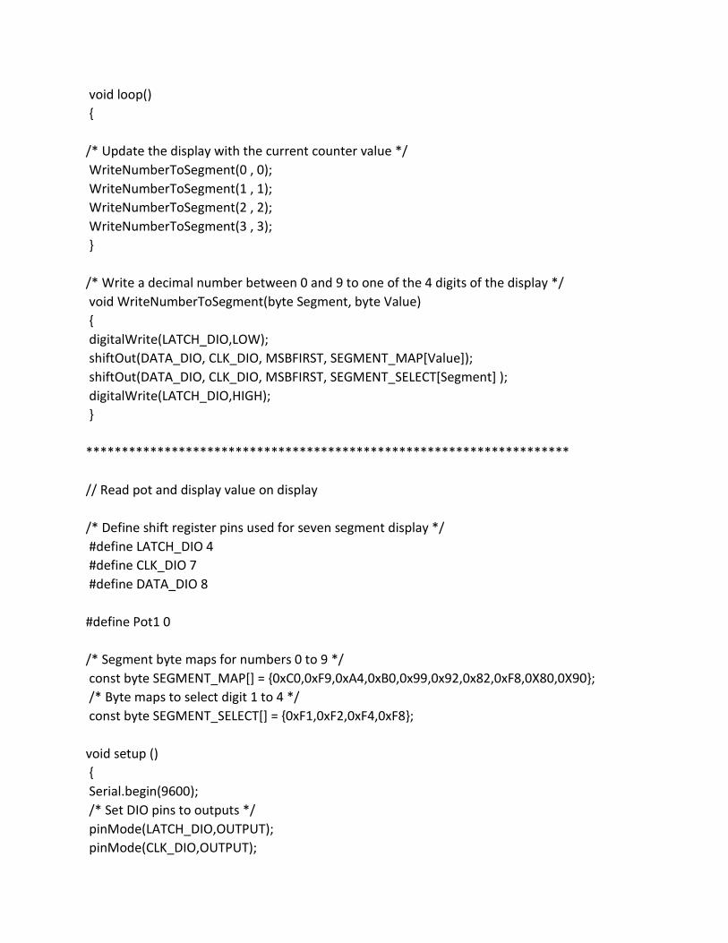
void loop()
{
/* Update the display with the current counter value */
WriteNumberToSegment(0 , 0);
WriteNumberToSegment(1 , 1);
WriteNumberToSegment(2 , 2);
WriteNumberToSegment(3 , 3);
}
/* Write a decimal number between 0 and 9 to one of the 4 digits of the display */
void WriteNumberToSegment(byte Segment, byte Value)
{
digitalWrite(LATCH_DIO,LOW);
shiftOut(DATA_DIO, CLK_DIO, MSBFIRST, SEGMENT_MAP[Value]);
shiftOut(DATA_DIO, CLK_DIO, MSBFIRST, SEGMENT_SELECT[Segment] );
digitalWrite(LATCH_DIO,HIGH);
}
********************************************************************
// Read pot and display value on display
/* Define shift register pins used for seven segment display */
#define LATCH_DIO 4
#define CLK_DIO 7
#define DATA_DIO 8
#define Pot1 0
/* Segment byte maps for numbers 0 to 9 */
const byte SEGMENT_MAP[] = {0xC0,0xF9,0xA4,0xB0,0x99,0x92,0x82,0xF8,0X80,0X90};
/* Byte maps to select digit 1 to 4 */
const byte SEGMENT_SELECT[] = {0xF1,0xF2,0xF4,0xF8};
void setup ()
{
Serial.begin(9600);
/* Set DIO pins to outputs */
pinMode(LATCH_DIO,OUTPUT);
pinMode(CLK_DIO,OUTPUT);

pinMode(DATA_DIO,OUTPUT);
}
/* Main program */
void loop()
{
int PotValue;
PotValue = analogRead(Pot1);
Serial.print(“Potentiometer: “);
Serial.println(PotValue);
/* Update the display with the current counter value */
WriteNumberToSegment(0 , PotValue / 1000);
WriteNumberToSegment(1 , (PotValue / 100) % 10);
WriteNumberToSegment(2 , (PotValue / 10) % 10);
WriteNumberToSegment(3 , PotValue % 10);
}
/* Write a decimal number between 0 and 9 to one of the 4 digits of the display */
void WriteNumberToSegment(byte Segment, byte Value)
{
digitalWrite(LATCH_DIO,LOW);
shiftOut(DATA_DIO, CLK_DIO, MSBFIRST, SEGMENT_MAP[Value]);
shiftOut(DATA_DIO, CLK_DIO, MSBFIRST, SEGMENT_SELECT[Segment] );
digitalWrite(LATCH_DIO,HIGH);
}

Operation of an LED:
Operation of a Button/Switch:
10 11 12 13
resi
sto
r
resi
sto
r
resi
sto
r
resi
sto
r
VCC - +3.3V
Arduino Processor
D1 D2 D3 D4
A3 A2 A1
resi
sto
r
resi
stor
resi
sto
r
VCC - +3.3V
Arduino Processor
S3 S2 S1

Operation of Speaker/Buzzer:
7-Segment Display Operation:
Common Anode Seven Segment Display with Pin Numbering
VCC - +3.3V
Arduino Due Speaker Schematic
Pin ~3
Arduino
Processor Buzzer
Resistor Transistor

Arduino Digital Pins:
Pin 4
Pin 8
Pin 7

Potentiometer Operations:
A0
resi
sto
r VCC - +3.3V
Arduino Processor
Potentiometer