sylax butterfly valves
TRANSCRIPT

• Sale leaflet p.2• Nomenclature p.3• Overall dimensions p.4• Top connections of the actuators p.5• Actuators p.6• Connecting flanges p.7-8• Normalisation p.9• Pressure p.10• Torque values - Pressure/Temperature diagram p.11• Flow rate (Kv) p.12• Head loss chart (∆p) p.13• Type of flange/ Tag/Traceability p.14• Bolts and nuts p.15-16• Installation p.17
Technical manual
Sylax butterfly valves (DN 25-100 mm)
Summary
uksylax25_100 - Updated 09/11/2011 1
Industrial processes and general services
Applications :
•Waterdistributionand supplywith the mainEuropeanapprovals,watertreatment,mostofthefluidsofgeneralservices.
•Industrialapplicationssuchas: Metallurgical, mining, paper-making, shipbuil-
ding, nuclear, environmental and mechanical, food industry (see our list of approvals).
•Forspecialapplications,especiallyfor particularlydifficultmedia,contactour technicalbackofficeteam.
Main characteristics :
•Multiple connections : centering lugs,tappedlugs.
•Verticalandhorizontaloperatingposition. •Highpowertransmissionwithrobust groovedconnectionbetweentheshaft andthedisc. •Easymaintenancebyremovingthecirclips •Interchangeablediscandliner. •Body in cast iron GJL1040, ductile iron
GJS1030,steelandstainlesssteel. •Body epoxy coated 80µm colour blue RAL
5017(alotofothercoatingsonoption,pleaseaskoursalesdepartment)
•Widechoiceofactuations.
Applications and main characteristics
•
•
AmountinginstructionspecifyingtheinstallationcharacteristicsandthecommissionoftheSylax25-100mmisavailableonourwebsitewww.socla.comoronrequestbyoursalesdepartment.

Technical manual Sylax DN 25-100 mm
Sale leaflet By concentrating the technologies and by integra-tingtechnicalsolutionsofthehighestlevels,Soclafulfilsitsambition: •competitivenessofastandardrange,•reliability,•comprehensiverangethankstoamultiplicityofsolutions.
uksylax25_100 - Updated 09/11/20112
•Safety anti-ejection circlip keeps shaft inplaceandallowseasymaintenance•Safety reinforced by a secondary water-tightness.
•Splinedrivenonepiece shaft connectedtofloatingdisc:
. high reliability of tightness and torque transmission in the long term.
•High power transmission with robust groovedconnectionbetweentheshaftandthedisc.
•Complete protection of the shaft and valvebodyfromfluids.
•Reliability of movements with self-lubricatingbearings.
•Identificationandtraceabilityensuredbyrivetedmetaltag:seeonpage14.

Technical manual Sylax DN 25-100 mm
uksylax25_100 - Updated 09/11/2011 3
9
87
10
116
24
351
Spare parts list
987
1
6
5
23
4
1011
Nb DESCRIPTION Qty MATERIALS ACCORDING TO NORMSMaterials EN ASTM JIS
1 Body 1
Ductileiron ENGJS400-15(JS1030) - FCD40Castiron ENGJL250(JL1040) - FC25Steel GE280(E280-480M) grWCB -
Stainlesssteel GX5CrNiMo19-11-2(1.4408) 316 SUS316
2 Liner 1
EPDM - - -WhiteEPDM - - -
Highcontentnitrile - - -Whitenitrile - - -
Carboxylatednitrile - - -CSM(Polyethylenchloro-sulfonated) - - -
Silicone - - -FKM - - -Buthyl - - -
Naturalrubber - - -
3 Disc 1Ductileiron ENGJS400-15(JS1030) - FCD40Stainlesssteel GX5CrNiMo19-11-2(1.4408) 316 SUS316Alu-bronze CuAl10Fe5Ni5(CC333G) - -
4 Stem 1Stainlesssteel X5CrNiCuNb16-4(1.4542) 630 SUS630Stainlesssteel X2CrNiMo17-12-2(1.4404) 316L SUS316LStainlesssteel X30Cr13(1.4028) 420 SUS420J2
5 - 6 Anti-frictionbearing 1 Zinccoatedsteel+PTFE - - -
7 Sealingandanti-extrusionbush 2 Plastic GrivoryXE3883black9915GV4 - -
8 O-ringseal 1 Nitrile/FKM - - -
9 Circlips 1 Stainlesssteel X30Cr13(1.4028) 420 SUS420J2Steel XC75 - -
10 Identificationplate 1 Aluminium ENAW-AL995(ENAW-1050A) - -11 Rivet 2 Alu/Stainlesssteel - - -

Technical manual Sylax DN 25-100 mm
uksylax25_100 - Updated 09/11/2011
Overall dimensions
H1H2
ED1
D2
L1
H5H1
L5
L6
• 4 Centring lugs
(1)Ductileironbody(JS1030),ductileirondisc(JS1030),EPDMliner.(2)Castironbody(JL1040),ductileirondisc(JS1030),EPDMliner.
DiameterFace
to face
Overall dimensions Iso top according to ISO 5211
Square drive outlet
Travel of the disc
Weight(kg)
DN NPS E L1 H1 H2 H4 N øR øS øT øU N° oC H3 Flat P D1 D2 (1) (2)
25 1 32 100 125 50 12 4 6,5 50 65 36 F05 11 16 11 6 1 - 1,632/40 1 1/2 32 144 130 57 12 4 6,5 50 65 36 F05 11 16 11 31 6,5 1,9 1,7
50 2 43 121 136 62 12 4 6,5 50 65 36 F05 11 16 11 33 6 2,6 2,665 2 1/2 46 136 145 84 12 4 6,5 50 65 36 F05 11 16 11 55 13 2,9 2,980 3 46 127 151 89 12 4 6,5 50 65 36 F05 11 16 11 73 20 3,6 3,6
100 4 52 149 175 106 10 4 6,5 50 65 36 F05 11 16 11 87 25 4,4 4,4
• 2 Centring lugs
(1)Stainlesssteelbody(1.4408),stainlesssteeldisc(1.4408),EPDMliner.(2)Steelbody(WCB),stainlesssteeldisc(1.4408),EPDMliner.
DiameterFace
to face
Overall dimensions Iso top according to ISO 5211
Square drive outlet
Travel of the disc
Weight(kg)
DN NPS E L5/L6 H1 H5 H4 N øR øS øT øU N° oC H3 Flat P D1 D2 (1) (2)
32/40 1 1/2 32 106/99 130 56 12 4 6,5 50 65 36 F05 11 16 11 31 6,5 1,7 1,650 2 43 121/99 136 73 12 4 6,5 50 65 36 F05 11 16 11 33 6 2,6 2,165 2 1/2 46 136/117 145 82 12 4 6,5 50 65 36 F05 11 16 11 55 13 3,1 2,480 3 46 150/136 151 93 12 4 6,5 50 65 36 F05 11 16 11 73 20 3,2 2,8
L2
• Tapped lugs and lugs with unthreaded holes*
*theversion«lugswithunthreadedholes»replacesthedoubleflangeversion((1)Ductileironbody(JS1030),ductileirondisc(JS1030),EPDMliner.(2)Stainlesssteelbody(1.4408),stainlesssteeldisc(1.4408),EPDMliner.
DiameterFace
to face
Overall dimensions Iso top according to ISO 5211
Square drive outlet
Travel of the disc
Weight(kg)
DN NPS E L1 H1 H2 H4 N øR øS øT øU N° oC H3 Plat P D1 D2 (1) (2)
32/40 1 1/2 32 146 130 57 12 4 6,5 50 65 36 F05 11 16 11 31 6,5 1,9 2,750 2 43 121 136 62 12 4 6,5 50 65 36 F05 11 16 11 33 6 3 3,365 2 1/2 46 135 145 70 12 4 6,5 50 65 36 F05 11 16 11 55 13 3,3 3,980 3 46 179 151 89 12 4 6,5 50 65 36 F05 11 16 11 73 20 4,2 4,8
100 4 52 206 175 103 10 4 6,5 50 65 36 F05 11 16 11 87 25 6
4
ØT
plat P N trous ØR sur ØS
Carré C
xC
4
ØU H3H4
NholesøRonøS
SquareCxC
FlatP

Technical manual Sylax DN 25-100 mm
uksylax25_100 - Updated 09/11/2011 5
Connecting kit for actuations
DN NPSIso top of the valve
Iso top of the actuationF03 F04 F05 F07 F10 F12 F14 F16
H1 H2 H1 H2 H1 H2 H1 H2 H1 H2 H1 H2 H1 H2 H1 H232 1 1/4
F05/o11
190
60
190
60
190
60
190
60
210
80
40 1 1/2 190 190 190 190 21050 2 199 199 199 199 21965 2 1/2 205 205 205 205 22580 3 210 210 210 210 230
100 4 235 235 235 235 255
DN NPS Iso top of the valve
Exceeding length fo the shaft H3Kit o9 o11 o14 o17 o22 o27 o36 o46
32 1 1/4
F05/o11
F03F04F05F07F10
7 9 12 15 20 2540 1 1/2
50 265 2 1/2
80 3100 4
N° N øR øSF03 4 5,5 36
F04 4 5,5 42
F05 4 6,5 50
F07 4 8,5 70
F10 4 10,5 102
F12 4 12,5 125
F14 4 17 140
F16 4 22 165
We recommend direct mounting of the actuation, otherwise see table below.
Reminder of the iso top dimen-sions EN ISO 5211 (see also theoveralldimensions).
Otherspecialexecutionsonrequest : actuated by par square driveandflataccordingtoENISO5211,subjectedtotechnicalfeasibility.
H1
H3H2
N trous ØR sur ØSNholesøRonøS

Technical manual Sylax DN 25-100 mm
uksylax25_100 - Updated 09/11/20116
(1) Pneumatic actuator only
Actuations
HAND LEVERPNEUMATIC ACTUATOR
ELECTRIC ACTUATOR
•1or2mechanicallimitswitch
For other options, please consult us.
•Switchbox: .mechanical .inductive .inductive+solenoidvalve .mechanical+solenoidvalve
•Inductivelimitswitch
•Positioners(1) .BURKERT1067
•Remotecontrol+emergencyhandwheel
•Auma •Bernard
•Socla•Belimo
•Rotork
•Notchedhandleverpolyamide(PCX)
GEAR BOX
•Manualgearboxincastiron
•Adjustableductileironhandlever(PRF)
•Notchedductileironhandlever(PCF)
ASS
EMBL
Y LE
VEL
1A
SSEM
BLY
LEV
EL 2
•Socla
Find below the different standard assembly combinations.Foranyotherinformation,pleaseaskourtechnicalDepartment.
Technical manual Sylax DN 25-100 mm
uksylax25_100 - Updated 09/11/2011 7
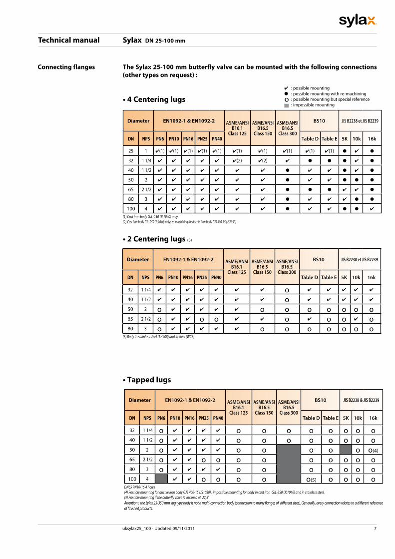
Connecting flanges The Sylax 25-100 mm butterfly valve can be mounted with the following connections (other types on request) :
o• 4 Centering lugs
(1) Cast iron body GJL-250 (JL1040) only.(2) Cast iron body GJL-250 (JL1040) only; re-machining for ductile iron body GJS 400-15 (JS1030)
4 :possiblemountingl :possiblemountingwithre-machining :possiblemountingbutspecialreference :impossiblemounting
Diameter EN1092-1 & EN1092-2 ASME/ANSIB16.1
Class 125
ASME/ANSIB16.5
Class 150
ASME/ANSIB16.5
Class 300
BS10 JIS B2238 et JIS B2239
DN NPS PN6 PN10 PN16 PN25 PN40 Table D Table E 5K 10k 16k
25 1 4(1) 4(1) 4(1) 4(1) 4(1) 4(1) 4(1) 4(1) 4(1) 4(1) l 4 l
32 11/4 4 4 4 4 4 4(2) 4(2) 4 l l l 4 l
40 1 1/2 4 4 4 4 4 4 4 l 4 4 l 4 l
50 2 4 4 4 4 4 4 4 l 4 4 l l l
65 2 1/2 4 4 4 4 4 4 4 l l l 4 4 l
80 3 4 4 4 4 4 4 4 l 4 4 4 l l
100 4 4 4 4 4 4 4 4 l 4 4 l l 4
• 2 Centering lugs (3)
Diameter EN1092-1 & EN1092-2 ASME/ANSIB16.1
Class 125
ASME/ANSIB16.5
Class 150
ASME/ANSIB16.5
Class 300
BS10 JIS B2238 et JIS B2239
DN NPS PN6 PN10 PN16 PN25 PN40 Table D Table E 5K 10k 16k
32 11/4 4 4 4 4 4 4 4 o 4 4 4 4 4
40 1 1/2 4 4 4 4 4 4 4 o 4 4 4 4 4
50 2 o 4 4 4 4 4 o o o o o o o65 2 1/2 o 4 4 o o 4 4 o 4 o o 4 o80 3 o 4 4 4 4 4 o o o o o o o
(3) Body in stainless steel (1.4408) and in steel (WCB)
• Tapped lugs
DN65 PN10/16 4 holes (4) Possible mounting for ductile iron body GJS 400-15 (JS1030) , impossible mounting for body in cast iron GJL-250 (JL1040) and in stainless steel.(5) Possible mounting if the butterfly valve is inclined at 22,5°Attention : the Sylax 25-350 mm lug type body is not a multi-connection body (connection to many flanges of different sizes). Generally, every connection relates to a different reference of finished products.
Diameter EN1092-1 & EN1092-2 ASME/ANSIB16.1
Class 125
ASME/ANSIB16.5
Class 150
ASME/ANSIB16.5
Class 300
BS10 JIS B2238 & JIS B2239
DN NPS PN6 PN10 PN16 PN25 PN40 Table D Table E 5K 10k 16k
32 11/4 o 4 4 4 4 o o o o o o o o40 1 1/2 o 4 4 4 4 o o o o o o o o50 2 o 4 4 4 4 o o o o o o(4)
65 2 1/2 o 4 4 o o o o o o o o o80 3 o 4 4 4 4 o o o o o o o
100 4 4 4 o o o o o(5) o o o o

Technical manual Sylax DN 25-100 mm
Connecting flanges • End of line mounting and downstream removingTheendoflinemountingandthedownstreamremoving,atambienttemperature,oftheSylax25-100mmbutterflyvalveislimitedtothepressurementionedonpage11accordingtothePEDdirective97/23/CE.
Thesemountingsareonlypossibleontappedlugsandlugswithunthreadedholes.
Downstreamremoving
Endoflinemounting
Forwafertypebodieswith4centeringlugs,theendoflinemountingcanbedoneinthefollowingconditions:-ambienttemperature-Forwaterornondangerousliquids(L2)-ForbutterflyvalvesPFA16barbetweenflanges-Forbutterflyvalveswithductileironbody-ForbutterflyvalveswithlinersinEPDMorhighcontentnitrile-Withinashortperiod(suchasmaintenance,...),15daysmaximum-Inpressureconditions(PFAorPS)suchas:seetable
DN PFAorPS (bar)
32-100 10
Usenutswithreducedface-to-facedimensionsbetweentheflangetobedismountedandthecenteringlugs.Usewashers,wide ones if needed, in order tomount thenutsonthelugs.Themountingandtheremovingmustbedonesuccessivelyandinoppositewayoneachnut.For themounting,applya reasonable torqueon thenuts,inordernottodamagethelugs,untilmetal-metalcontactbetweenflangeandbody.Forflangeswith8rods,only4areusedtomaintainthevalveindownstreamremoving;the8rodsmustbere-mountedforanormalusebetweenflanges.Incaseofunexpecteddownstreamremoving,integrateandscrewsuccessivelyand inoppositeway,betweenthe lugsand the flange tobe removed, the4nutswhichhold thebutterflyvalve.
Downstreamremoving
Mountingbetweenflanges
8 uksylax25_100 - Updated 09/11/2011

Technical manual Sylax DN 25-100 mm
uksylax25_100 - Updated 09/11/2011 9
Normalisation
AmountinginstructionspecifyingtheinstallationcharacteristicsandthecommissionoftheSylax25-100mmisavailableonourwebsitewww.socla.comoronrequestbyoursalesdepartment.
• Iso top connection for actuations : AccordingtoENISO5211
• Face to face :Accordingto 558-1series20 ISO5752series20 API609table2
• Connecting flanges : seeonpage8Accordingto EN1092-1andEN1092-2 ASME/ANSIB16.5 BS10-dandBS10-e JISB2238andJISB2239
• Tests : AccordingtoEN12266-1 Resistanceandtightnessofthebody:testP11(1,5xallowableoperatingpressure) Tightnessoftheseat:testP12rateA(1,1xallowableoperatingpressure)
AccordingtoEN12266-2 Anti-staticdesign:testF21
• European Directives : Ourbutterflyvalvesareinaccordancetothesafetyrequirementsofthefollowingdirectives.:
Directive97/23/CE: EquipmentsunderpressurePED (PressureEquipmentDirective)Appliestothedesign,manufacturingandtheassessmentoftheconformityofpressureequipment,themaximumallowablepressureofwhichis0.5bar.Pressureequipmentforwatersupply,distribution,anddisposalofwaterisexcluded.Dependingonthetypeofpressureequipment,maximumallowabletemperature(PS),DN,physicalnatureofthefluid(liquid,gasorvapour)andthedegreeofdangerofthefluid(group1/2)*,thedirectiveclassifiesthissameequipmentintodifferentcategories(article3.3,I,II,III,IV),requiredfortheassessmentofconformitywithCEmarking.Theequipmentdefinedinarticle3.3ofthedirectivemustnotbeartheCEmarking.(*)Group1:hazardous fluids (directive 67/548/EEC) / explosive / highly flammable /easily flammable / flammable / very toxic / toxic
/combustionagents.Group2:allotherfluids
Important notice:theindicatedpressureforthedifferentcategoriesoffluids(L1/L2/G1/G2)isundernoconditionaguaranteeofuse.Therefore,itisessentialtovalidatetheuseofproductsundergivenoperatingconditions.DanfossSoclaisnotresponsibleforalterationoftheproductstoworkingconditionsnotpreviouslyspecifiedbythecustomer.Inordertofacilitateyourchoiceregardingthesenewregulatoryrequirements,DanfossSoclahasputthenecessaryinformationconcerningproductswithCEmarking,specificationsheetsandproductidentificationplatesatyourdisposalinthepricelist(+seeadditionalexplanationsonthedetachableslip).Inaddition,theoperatinginstructionsareavailableonourwebsitewww.socla.comorbysimplerequestfromoursalesdepartment.
MachineryDirective2006/42/CE: MachineryDirectiveInitsAppendixIitsetsacertainnumberofEssentialHealthandSafetyRequirementswhichmustbemet.Itappliestomotorisedbutterflyvalves,(withelectric,pneumaticorhydraulicactuators).AccordingtothisDirective,thesesetsare“PartlyCompletedMachineries”designedforbeingintegratedintoamachine.“PartlyCompletedMachinery”meansanassemblywhichisalmostmachinerybutwhichcannotinitselfperformaspecificapplication.Adrivesystemispartlycompletedmachinery.Partlycompletedmachineryisonlyintendedtobeincorporatedintoorassembledwithothermachi-neryorotherpartlycompletedmachineryorequipment,therebyformingmachinerytowhichthisDirectiveapplies.

Technical manual Sylax DN 25-100 mm
uksylax25_100 - Updated 09/11/201110
Pressure DIRECTIVE 97/23/CE Equipments under pressure.Productsmanufacturedinconformitywiththerequirementsofthedirective,accordingtopressure,DNandfluid(seeontheprecedentpage).
PS : Maximum allowable pressure (in bar) according to Directive 97/23/CEPFA : Allowable operating pressure (in bar) for supply, distribution and disposal of water.
LINERS DN mm Cat. MOUNTING PFAPS
L1 L2 G1 G2
6bar
EPDM,Nitrile(CC333Gdisc),WhiteEPDM
32to150 3.3Flanges 6 6 6 6
Endofline 4 4 4 4200to350 I
Flanges 6 6 6 6Endofline 4 4 4 4
Nitrile(exceptCC333Gdisc),Neoprene,Butyl,Hypalon,Naturalrubber,Whitenaturalrubber.
32to100 IFlanges 6 6 6 6 6
Endofline 4 4 4 4125to350 II
Flanges 6 6 6 6 6Endofline 4 4 4 4
10bar
EPDM,Nitrile(CC333Gdisc),WhiteNitrile,CarboxylatedNitrile,WhiteEPDM
25to100 3,3Flanges 10 10 10 10
Endofline 6 6 6 6125 & 150 I
Flanges 10 10 10 10Endofline 6 6 6 6
200to350 IFlanges 10 10 10 10
Endofline 6 6 6 6
Nitrile(exceptCC333Gdisc),FKM
25 3,3Flanges 10 10 10 10 10
Endofline 6 6 6 632to100 I
Flanges 10 10 10 10 10Endofline 6 6 6 6
125to350 IIFlanges 10 10 10 10 10
Endofline 6 6 6 6
Silicone
32to100 IFlanges 10 10 10 10 10
Endofline 6 6 6 6125to150 II
Flanges 10 10 10 10 10Endofline 6 6 6 6
200to350 IIFlanges 6 6 6 6 6
Endofline 4 4 4 4
16bar
EPDM,Nitrile(CC333Gdisc)
32to100 3,3Flanges 16 16 16 10
Endofline 12 12 12 10125 I
Flanges 16 16 16 10Endofline 12 12 12 10
150 IFlanges 16 10 16 10
Endofline 12 6 12 10200to300 I
Flanges 16 10 16 10Endofline 10 6 10 10
350 IFlanges 16 10 16 10
Endofline 8 6 8 8
Nitrile(exceptCC333Gdisc),Neoprene,Butyl,Hypalon,Naturalrubber,Whitenaturalrubber
32to100 IFlanges 16 16 16 10 16
Endofline 12 12 12 12
125 & 150 IIFlanges 16 16 16 10 16
Endofline 12 12 12 12
200to300 IIFlanges 16 16 16 10 10
Endofline 10 10 10 10
350 IIFlanges 16 16 16 10 10
Endofline 8 8 8 8
20bar
EPDM,Nitrile(CC333Gdisc)32to250 3,3
Flanges 20 20Endofline 12 12
300&350 IFlanges 20 20
Endofline 12 12
Nitrile(exceptCC333Gdisc),Neo-prene,Butyl,Naturalrubber,Whitenaturalrubber
32to100 3,3Flanges 20 20 20
Endofline 12 12 12
125to350 IIFlanges 20 20 20
Endofline 12 12 12
25bar
EPDM,Nitrile(CC333Gdisc) 32to150 3,3Flanges 25 25
Endofline 16 16
Nitrile(exceptCC333Gdisc)32to80 3,3
Flanges 25 25 25Endofline 16 16 16
100to150 IIFlanges 25 25 25
Endofline 16 16 16
ATTENTIONGas G1 and G2 : The max. pressure is 6 bar when using cast iron GGG25 bodies (FGL 250)
Technical manual Sylax DN 25-100 mm
uksylax25_100 - Updated 09/11/2011 11
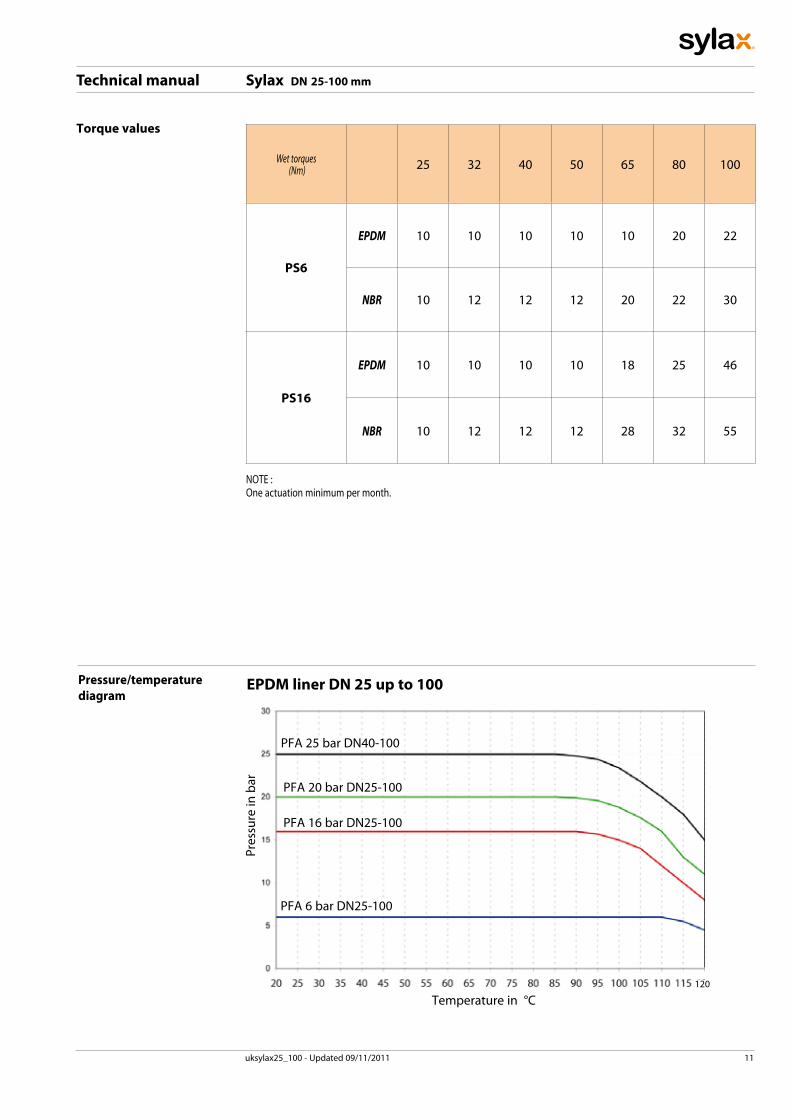
Torque values
Wet torques (Nm) 25 32 40 50 65 80 100
PS6
EPDM 10 10 10 10 10 20 22
NBR 10 12 12 12 20 22 30
PS16
EPDM 10 10 10 10 18 25 46
NBR 10 12 12 12 28 32 55
NOTE:Oneactuationminimumpermonth.
Pressure/temperaturediagram
EPDM liner DN 25 up to 100
Temperaturein°C
Pressurein
bar
PFA25barDN40-100
PFA20barDN25-100
PFA16barDN25-100
PFA6barDN25-100
120

Technical manual Sylax DN 25-100 mm
uksylax25_100 - Updated 09/11/201112
Flow rate (Kv) Thebutterflyvalve isnotthebestproductforregula-tingNevertheless,theSylax25-350mmbutterflyvalvecanbeusedtoregulatebyanopeningstagebetween30°and90°.A regulation in the opening stage lower than 30° isnotadvisablebecauseofoverspeed,cavitationeffect,whichcoulddamageprematurelythevalve.
Kv = volume of water in m3/h through a valve at a preset opening stage and under a head loss of 1 bar.
Themaximumflowvelocityofthefluidthroughthevalvemustnotexceed:-3m/sforliquidfluids.Between3and5m/s,theuseoftheSylax25-100mmbutterflyvalveispossible,butthephenomenaofcavitation,noise,vibrationandwaterhammeringincrease.-20m/sforgas.Between20and25m/s,theuseoftheSylax25-100mmbutterflyvalve ispossible,butthephenomenaofcavitation,noise,vibrationandwaterhammeringincrease.-forpulverulentorpastefluids:pleaseconsultus.
OPENING STAGE - Stainless steel discDN 10° 20° 30° 40° 50° 60° 70° 80° 90°25 - - - 3 8 16 27 35 40
32/40 - - - 5 12 25 40 56 6250 - - 1 8 18 33 54 71 7965 - - 6 19 41 76 118 158 17480 - 3 18 43 79 138 211 252 275
100 - 15 38 83 154 253 368 458 496
DEGRES D'OUVERTURE
DN
0 10 3020 60 705040 9080
Kv
8
65
4
32.5
2
1.5
10
1
100
15
20
2530
40
5060
80
800
600500
400
300250
200
150
1000
10000
1500
2000
25003000
4000
50006000
8000
8000
60005000
4000
30002500
2000
1500
10000
1000
150
200
250300
400
500600
800
80
6050
40
3025
20
15
100
10
4
56
8
1500
2000
25003000
4000
GALLON/MIN M3/H
65
50
100
80
32/40
25
OPENING STAGES

Technical manual Sylax DN 25-100 mm
uksylax25_100 - Updated 09/11/2011 13
DEBIT M3/HFLOW
GALLON/MIN
PSI
M/CE
100
DN
1 3 4 5 10 15
102 3 4 5
20
30
40
60
80
1.7.2 .3 .4 .5
6 7 8
6 7 81.5
2
.6 .8.15P
10
1000
150
200250300
400500600
800
10000
2000
3000
4000
6000
100
80
60
40
150
200
300
400
1000
1500
2000
3000
4000
6000
10000
20000
30000
40000
25000
15000
8000
600
800
5000
2500
8000
5000
2500
1500
M/WC
25
32-4050
65
80
100
Head loss diagram (Δp)

Technical manual Sylax DN 25-100 mm
uksylax25_100 - Updated 09/11/201114
Type of flange The Sylax 25-100mm butterfly valve hasbeen designed to be mounted on nor-malised standard flanges. Only standardflangestype11,21and34accordingtoEN1092arequitecompatible.
Forothertypesofflanges,refertothetablebelow.Nonappropriateconnectionswillcancelourguarantee.
NOTE :The use of expansion seals, as well as the use of elastomer coated flanges, between the flange and the valve are strictly forbidden.
ØA1
ØB
ØA0 ØA2
DN Ø A0 Ø A1 mini Ø A2 maxi Ø B mini25 1 32 - 44 6032 1 1/4 43 33 51 8040 1 1/2 43 33 51 8050 2 54 40 60 9065 2 1/2 70 59 74 11080 3 85 78 91 128
100 4 100 97 108 148
Tag / traceability
Rep Description1 Nameofthevalve2 Reference3 Materialofthedisc4 Materialoftheliner5 PressurePSbetweenflangesL1/L2(liquid)6 PressurePSbetweenflangesG1/G2(gas)7 PressurePSendflangeL1/L2(liquid)8 PressurePFAwater20°C9 PressurePSendflangeG2(gas)
10 Numberofmanufacturingorder11 NotifiedBodyNumberfortheDirectivePED97/23/CE12 Manufacturingdate13 Connectingflanges14 Limitofuse15 Approvalinformationzone
2
4
6
9
12
10
11
13
14
7
5
3
1
15
8

Technical manual Sylax DN 25-100 mm
uksylax25_100 - Updated 09/11/2011
Bolts and nuts Note :Boltsandnutsarenotpartofourstandardsupply.
DN NPS a e
EN 1092PN6
EN 1092PN10
EN 1092PN16
EN 1092PN25
ASME/ANSIB16.5Class150
*NbrodsorNbscrew
ØV c
*NbrodsorNbscrew
ØV c
*NbrodsorNbscrew
ØV c
*NbrodsorNbscrew
ØV c
*NbrodsorNbscrew
ØV Metric
ØV UNC** c
25 1 32 -- 4 M10 16 4 M12 18 4 M12 18 4 M12 18 4 M14 1/2’’ 18
32/40 11/2 32 14 4 M12 18 4 M16 24 4 M16 24 4 M16 24 4 M14 1/2’’ 18
50 2 43 18 4 M12 18 4 M16 24 4 M16 24 4 M16 24 4 M16 5/8’’ 24
65* 21/2 46 20 4 M12 18 8* M16 24 8* M16 24 8 M16 24 4 M16 5/8’’ 24
80 3 46 20 4 M16 24 8 M16 24 8 M16 24 8 M16 24 4 M16 5/8’’ 24
100 4 52 24 4 M16 24 8 M16 24 8 M16 24 8 M20 26 8 M16 5/8’’ 24
DN NPS a e
BS10-d BS10-e JIS2238&JIS22395K
JIS2238&JIS223910K
JIS2238&JIS223916K
*NbrodsorNbscrew
ØVUNC c
*NbrodsorNbscrew
ØVUNC c
*NbrodsorNbscrew
ØV c
*NbrodsorNbscrew
ØV c
*NbrodsorNbscrew
ØV c
25 1 32 -- 4 1/2’’ 18 4 1/2’’ 18 4 M10 16 4 M16 24 4 M16 24
32/40 11/2 32 14 4 1/2’’ 18 4 1/2’’ 18 4 M12 18 4 M16 24 4 M16 24
50 2 43 18 4 5/8’’ 24 4 5/8’’ 24 4 M12 18 4 M16 24 8 M16 24
65 21/2 46 20 4 5/8’’ 24 4 5/8’’ 24 4 M12 18 4 M16 24 8 M16 24
80 3 46 20 4 5/8’’ 24 4 5/8’’ 24 4 M16 24 8 M16 24 8 M20 26
100 4 52 24 4 5/8’’ 24 8 5/8’’ 24 8 M16 24 8 M16 24 8 M20 26* WAFER TYPE BODY AND LUGS WITH UNTHREADED HOLES :Assembly by rods : number of nuts and washer = 2 x Number of rods (above)Assembly by bolts : Number of nuts = Number of screws (above) and number of washer = 2 x Number of nuts
* LUG TYPE BODY :Assembly by screws : Number of screw per face (above) and number of washer is the same
** ASME / ANSI B16.5 Class 150 : Standard version : metric threading; UNC threading : please consult us.
*Forflangesincastorductileiron4holesM16andforflangesinsteel8holesM16onthesamedrillingcircle.
For wafer type and lugs with unthreaded holes ; assembly by rods :
L1 = a + 2(b+c)L1 = minimumlengthofrodsa = widthofthebutterflyvalve(facetofacedimension)b = thicknessoftheflange(customer)c = thicknessofwasher+thicknessofnut+exceedinglengthoftherod.
c b a b c
L1
ØV
15

Technical manual Sylax DN 25-100 mm
uksylax25_100 - Updated 09/11/201116
For wafer type and lugs with unthreaded holes ; assembly by bolts :
L2 = a + 2b + c + jL2 = minimumlengthunderheadofscrewa = widthofthebutterflyvalveb = thicknessoftheflange(customer)c = thicknessofwasher+thicknessofnut+exceedinglengthoftherodj = thicknessofwasherattheheadofthescrew.
L2
j b a b c
ØV
L1c b a b c
L2
b a b cj
L3j b a
c Version lug type with unthreaded holes, (permanent downstream dismantling) assembly by bolts :
L3 = a/2 + b + c + jL3 = minimumlengthunderheadofscrewa = widthofthebutterflyvalve(facetofacedimension)b = thicknessoftheflange(customer)c = thicknessofwasher+thicknessofnut+exceedinglengthoftherodj = thicknessofwasherunderheadofscrew
Mountingincaseofdownstreampipeworkdismantling(seepage8).Usenutswithreducedface-to-facedimensionsbetweenthebutterflyvalveandthedownstreamflange.
Mountingincaseofdownstreampipeworkdismantling(seepage8).Usenutswithreducedface-to-facedimensionsbetweenthebutterflyvalveandthedownstreamflange.
For lug type body ; assembly by screws :
L6 ≤ b + e + j with L7 ≥ L6 - (b + j)L6 = maximumlengthunderheadofscrewL7 = minimumlengthofthethreadingofthescrewa = widthofthebutterflyvalve(facetofacedimension)b = thicknessoftheflange(customer)e = maxidepthofscrewj = thicknessofwasher
L7
L6
j e b
ØV
Bolts and nuts

Technical manual Sylax DN 25-100 mm
uksylax25_100 - Updated 09/11/2011 17
Installation • General remarks :Forsafetyreasons,theinstallationmusttakeplaceunder the supervision of authorisedpeople takingaccountoflocalsafetyinstructionsandadvice.Thehandlingofbutterflyvalvesandtheircontrolsmust be done by staff trained in all technicalaspectsoftheiroperation.Before installation the pipes must be depressu-risedandpurged (emptyof its fluid) inorder toavoidanydangertotheoperator.Thepipeworkmustbecorrectlyalignedso thatnoextrastressisexertedonthevalvecasing.
Check the compatibility of the connection flangesagainsttheoperatingpressure:thePNnumberoftheflangesmustbegreaterorequaltotheope-ratingpressure.Thevalveisamachinedpieceofequipmentandmustnotbeusedtopriseaparttheflanges.
A mounting instruction specifying the installationcharacteristics and the commission of the Sylax25-100 mm is available on our web site www.socla.com oronrequestbyoursalesdepartment.
• Installation conditions :It is recommended that thedistancesmentionedbelow be respected in order to prolong the lifetimeofthevalve.
Mounting the valve close to pipework junctionsplaces it in turbulent zones which increase itswear.
5-6
DN
1 DN
DN
2-3
DN
DN
1 DN
DN
2-3
DN
1 DN
DN
2-3
DN
DN
1 DN
DN
Socla sas365ruedulieutenantPutier71530VIREYLEGRANDPostaladdress:BP1027371107CHALONSURSAONECedex
Tel:33385974252Fax:33385979742http://www.socla.come-mail:[email protected]
Soclacanacceptnoresponsibilityforpossibleerrorsincatalogue,brochuresandotherprintedmaterial.Soclareservetherighttoalteritsproductswithoutnotice.Thisalsoappliestoproductsalreadyagreed.Alltrademarksinthismaterialarethepropertyoftherespectivecompanies.Allrightreserved.