swzt operators manual - scag.com · operating, maintenance and adjustment instructions in ... the...
TRANSCRIPT

PART NO. 03356PRINTED 9/2013PRINTED IN USA
© 2013Scag Power EquipmentDivision of Metalcraft of Mayville, Inc.
Congratulations on owning a Scag mower! This manual contains the operating instructions and safety information for your Scag mower. Reading this manual can provide you with assistance in maintenance and adjustment procedures to keep your mower performing to maximum efficiency. The specific models that this book covers are listed on the inside cover. Before operating your machine, please read all the information enclosed.
SWZTWalk-BehindModel: SWZT36-14FS SWZT48-15FS
OPERATOR’S MANUAL

WARNING
FAILURE TO FOLLOW SAFE OPERATING PRACTICES MAY RESULT IN SERIOUS INJURY OR DEATH.
Read this manual completely as well as other manuals that came with your mower.•
ALWAYS FOLLOW OSHA APPROVED OPERATION.•
DO NOT operate on steep slopes. •
Always travel across slopes.•
DO NOT mow on wet grass. Wet grass reduces traction and steering control.•
Keep all shields in place, especially the grass discharge chute.•
Before performing any maintenance or service, stop the machine and remove the •spark plug wire and ignition key.
If a mechanism becomes clogged, stop the engine before cleaning.•
Keep hands, feet and clothing away from power-driven parts.•
Keep others off the mow• er (only one person at a time)
REMEMBER - YOUR MOWER IS ONLY AS SAFE AS THE OPERATOR!
HAzARD CONTROL AND ACCIDENT PREvENTION ARE DEPENDENT UPON THE AWARENESS, CONCERN, PRUDENCE, AND PROPER TRAINING OF THE PERSONNEL INvOLvED IN THE OPERATION, TRANSPORT, MAINTENANCE, AND STORAGE OF THE EqUIPMENT.
This manual covers the operating instructions and illustrated parts list for:
SWzT36-14FS with a serial number of J7200001 to J7299999
SWzT48-15FS with a serial number of J7300001 to J7399999
Always use the entire serial number listed on the serial number tag when referring to this product.

I
RTable of Contents
Table of ContentsGENERAL INFORMATIONSECTION 1 - ...................................................................................1
1.1 INTRODUCTION ...........................................................................................................................................1
1.2 DIRECTION REFERENCE ...........................................................................................................................1
1.3 SERvICING THE ENGINE AND DRIvE TRAIN COMPONENTS .................................................................1
1.4 SYMBOLS ....................................................................................................................................................2
SAFETY INFORMATIONSECTION 2 - ......................................................................................32.1 INTRODUCTION ...........................................................................................................................................3
2.2 SIGNAL WORDS ..........................................................................................................................................3
2.3 BEFORE OPERATION CONSIDERATIONS ................................................................................................3
2.4 OPERATION CONSIDERATIONS ................................................................................................................4
2.5 MAINTENANCE CONSIDERATIONS & STORAGE ....................................................................................6
2.6 USING A SPARk ARRESTOR .....................................................................................................................6
2.7 SPARk IGNITION SYSTEM .........................................................................................................................6
2.8 SAFETY AND INSTRUCTIONAL DECALS .................................................................................................7
SPECIFICATIONSSECTION 3 - ................................................................................................83.1 ENGINE ........................................................................................................................................................8
3.2 ELECTRICAL ...............................................................................................................................................8
3.3 ENGINE DECk .............................................................................................................................................8
3.4 CUTTER DECk ............................................................................................................................................8
3.5 WEIGHTS AND DIMENSIONS .....................................................................................................................9
3.6 PRODUCTIvITY ...........................................................................................................................................9
OPERATING INSTRUCTIONSSECTION 4 - ...........................................................................104.1 CONTROLS AND INSTRUMENT IDENTIFICATION ................................................................................10
4.2 SAFETY INTERLOCk SYSTEM ................................................................................................................11
4.3 INITIAL RUN-IN PROCEDURES ................................................................................................................11
4.4 STARTING THE ENGINE ...........................................................................................................................11
4.5 GROUND TRAvEL AND STEERING .........................................................................................................11
4.6 ENGAGING THE DECk DRIvE (CUTTER BLADES) ................................................................................12
4.7 HILLSIDE OPERATION ..............................................................................................................................13
4.8 PARkING THE MOWER .............................................................................................................................13
4.9 AFTER OPERATION ..................................................................................................................................13
4.10 REMOvING CLOGGED MATERIAL ........................................................................................................13
4.11 MOvING MOWER WITH ENGINE STOPPED ..........................................................................................14
4.12 RECOMMENDATIONS FOR MOWING ....................................................................................................14
TROUBLESHOOTING CUTTING CONDITIONSSECTION 5 - ...............................................15

II
R Table of Contents
ADJUSTMENTSSECTION 6 - .................................................................................................186.1 PARkING BRAkE ADJUSTMENT ............................................................................................................18
6.2 NEUTRAL ADJUSTMENT .........................................................................................................................18
6.3 NEUTRAL LATCH ADJUSTMENT ............................................................................................................19
6.4 TRACkING ADJUSTMENT ........................................................................................................................19
6.5 THROTTLE CONTROL AND CHOkE ADJUSTMENTS ............................................................................20
6.6 BELT ADJUSTMENT .................................................................................................................................20
6.7 BELT ALIGNMENT .....................................................................................................................................20
6.8 CUTTER DECk ADJUSTMENTS ..............................................................................................................20
6.9 ELECTRIC CLUTCH ADJUSTMENT .........................................................................................................22
MAINTENANCESECTION 7 - ..................................................................................................247.1 MAINTENANCE CHART - RECOMMENDED SERvICE INTERvALS ......................................................24
7.2 LUBRICATION ............................................................................................................................................25
7.3 HYDRAULIC SYSTEM ...............................................................................................................................26
7.4 ENGINE OIL ...............................................................................................................................................28
7.5 ENGINE FUEL SYSTEM ............................................................................................................................28
7.6 ENGINE AIR CLEANER .............................................................................................................................29
7.7 CUTTER BLADES ......................................................................................................................................29
7.8 TIRES ..........................................................................................................................................................30
ILLUSTRATED PARTS LISTSECTION 8 - ..............................................................................318.1 SCAG APPROvED ATTACHMENTS AND ACCESSORIES. .....................................................................31
36" CUTTER DECk ..........................................................................................................................................32
48" CUTTER DECk ..........................................................................................................................................34
CUTTER DECk CONTROLS ...........................................................................................................................36
ENGINE DECk & HYDRAULIC SYSTEM ........................................................................................................38
STEERING CONTROLS ...................................................................................................................................40
BRAkE COMPONENTS ..................................................................................................................................42
ELECTRICAL SYSTEM AND THROTTLE CONTROL ....................................................................................44
SWzT FUEL SYSTEM ......................................................................................................................................46
zT-2800 HYDRAULIC AXLE ASSEMBLY ........................................................................................................48
REPLACEMENT DECALS AND INFORMATION PLATES .............................................................................50
SWzT ELECTRICAL SCHEMATIC ..................................................................................................................52
LIMITED WARRANTY - COMMERCIAL EqUIPMENSECTION 9 - T ..............Following Section 8

1
RSection 1
INTRODUCTION1.1
Your mower was built to the highest standards in the industry. However, the prolonged life and maximum efficiency of your mower depends on you following the operating, maintenance and adjustment instructions in this manual.
If additional information or service is needed, contact your Scag Power Equipment Dealer.
We encourage you to contact your dealer for repairs. All Scag dealers are informed of the latest methods to service this equipment and provide prompt and efficient service in the field or at their service shop. They carry a full line of Scag service parts.
- IMPORTANT -
The replacement of any part on this product by other than the manufacturer's authorized replacement part may adversely affect the performance, durability or safety of this product.
Use of other than original Scag replacement parts will void the warranty.
When ordering parts, always give the model and serial number of your mower. The serial number plate is located on the frame of the machine near the engine and hydraulic pump as shown in Figure 1-1.
R
MODEL
SERIAL
Division of Metalcraft o
f Mayville
, Inc.
Mayville, W
isconsin 53050
Patents Issued and Pending
SERIAL NUMBERPLATE LOCATION
Mower Serial Number Plate LocationFigure 1-1.
GENERAL INFORMATIONUSE ONLY SCAG APPROvED ATTACHMENTS AND ACCESSORIES.
Attachments and accessories manufactured by companies other than Scag Power Equipment are not approved for use on this machine. See Section 8-1.
WARNINGFor pictorial clarity, some illustrations and figures in this manual may show shields, guards or plates open or removed. Under no circumstances should your mower be operated without these devices in place.
All information is based upon product information available at the time of approval for printing. Scag Power Equipment reserves the right to make changes at any time without notice and without incurring any obligation.
DIRECTION REFERENCE1.2
The “Right” and “Left”, “Front” and “Rear” of the machine are referenced from the operator’s right and left when in the normal operating position and facing the forward travel direction.
SERvICING THE ENGINE AND DRIvE 1.3 TRAIN COMPONENTS
The detail servicing and repair of the engine and transmission are not covered in this manual; only routine maintenance and general service instructions are provided. For service of these components during the limited warranty period, it is important to contact your Scag dealer or find a local authorized servicing agent of the component manufacturer. Any unauthorized work done on these components during the warranty period may void your warranty.

2
R Section 1
SYMBOLS1.4
SYMBOL DESCRIPTION SYMBOL DESCRIPTION
Choke
Transmission
Parking Brake
48071S
Spinning Blade
On/Start
Spring Tension on Idler
Off/Stop
Oil
Falling Hazard
Thrown Object Hazard
Fast
Slow
Continuously Variable - Linear
Cutting Element - Basic Symbol
481039S
Pinch Point
Cutting Element - Engage
Hour meter/Elapsed Operating Hours
Cutting Element - Disengage
Keep Bystanders Away
Read Operator's Manual

3
RSection 2
INTRODUCTION2.1
Your mower is only as safe as the operator. Carelessness or operator error may result in serious bodily injury or death. Hazard control and accident prevention are dependent upon the awareness, concern, prudence, and proper training of the personnel involved in the operation, transport, maintenance and storage of the equipment. Make sure every operator is properly trained and thoroughly familiar with all of the controls before operating the mower. The owner/user can prevent and is responsible for accidents or injuries occurring to themselves, other people or property.
READ THIS OPERATOR’S MANUAL BEFORE ATTEMPTING TO START YOUR MOWER.
A replacement manual is available from your authorized Scag Service Dealer or by contacting Scag Power Equipment, Service Department at P.O. Box 152, Mayville, WI 53050 or contact us via the Internet at www.scag.com. The manual for this machine can be downloaded by using the model and serial number or use the contact form to make your request. Please indicate the complete model and serial number of your Scag product when requesting replacement manuals.
SIGNAL WORDS2.2
This symbol means “Attention! Become Alert! Your Safety is Involved!" The symbol is used with the following signal words to attract your attention to safety messages found on the decals on the machine and throughout this manual. The message that follows the symbol contains important information about safety. To avoid injury and possible death, carefully read the message! Be sure to fully understand the causes of possible injury or death.
SIGNAL WORD:
It is a distinctive word found on the safety decals on the machine and throughout this manual that alerts the viewer to the existence and relative degree of the hazard.
DANGER
The signal word “DANGER” denotes that an extremely hazardous situation exists on or near the machine that could result in high probability of death or irreparable injury if proper precautions are not taken.
WARNING
The signal word “WARNING” denotes that a hazard exists on or near the machine that can result in injury or death if proper precautions are not taken.
CAUTION
The signal word “CAUTION” is a reminder of safety practices on or near the machine that could result in personal injury if proper precautions are not taken.
Your safety and the safety of others depends significantly upon your knowledge and understanding of all correct operating practices and procedures of this machine.
BEFORE OPERATION 2.3 CONSIDERATIONS
WARNINGCheck all hydraulic connections for tightness. Inspect all hydraulic hoses and / or lines to insure they are in good condition before operating.
NEVER allow children to operate this mower. Do not 1. allow adults to operate this machine without proper instructions.
Do not mow when children and/or others are 2. present. Keep children out of the mowing area and in the watchful care of a responsible adult other than the operator. Be alert and turn machine off if a child enters the area.
SAFETY INFORMATION

4
R Section 2
DO NOT allow children to ride or play on the3.machine, it is not a toy.
Clear the area to be mowed of objects that could be4.picked up and thrown by the cutter blades.
DO NOT carry passengers.5.
DO NOT operate the machine under the influence of6.alcohol or drugs.
7. If the operator(s) or mechanic(s) cannot read English, it is the owner's responsibility to explain this material to them. A Spanish decal kit is available for this model. See your local Scag Dealer.
DO NOT wear loose fitting clothing. Loose clothing,8.jewelry or long hair could get tangled in movingparts. Do not operate the machine wearing shorts;always wear adequate protective clothing includinglong pants. Wearing safety glasses, safety shoes anda helmet is advisable and is required by some localordinances and insurance regulations.
WARNINGAlways wear hearing protection. Operating this machine over prolonged periods of time can cause loss of hearing.
Keep the machine and attachments in good9.operating condition. Keep all shields and safetydevices in place. If a shield, safety device or decalis defective or damaged, repair or replace it beforeoperating the machine.
WARNINGThis machine is equipped with an interlock system intended to protect the operator and others from injury. This is accomplished by preventing the engine from starting unless the deck drive is disengaged and the transmission is in neutral. The system shuts off the engine if the operator releases the operator pressence levers with the deck drive engaged and/or the transmission is not in neutral. Never operate equipment with the interlock system disconnected or malfunctioning.
Be sure the interlock switches are functioning10.correctly.
Fuel is flammable; handle it with care. Fill the fuel11.tank outdoors. Never fill it indoors. Use a funnel orspout to prevent spillage. Clean up any spillagebefore starting the engine.
DO NOT add fuel to a running or hot engine. Allow12.the engine to cool for several minutes before addingfuel. Never fuel indoors or inside enclosed trailers.
Keep flammable objects (cigarettes, matches, etc.),13.open flames and sparks away from the fuel tank andfuel container. Use only approved containers.
See Section 7.4 ENGINE FUEL SYSTEM for fueling14.procedure.
Equipment must comply with the latest requirements15.per SAE J137 and/or ANSI/ASAE S279 when drivenon public roads.
Do not operate without the side discharge chute16.installed and in the down position or with an optionalgrass catcher or mulch plate completely installed.
Check the blade mounting bolts at frequent intervals17.for proper tightness.
OPERATION CONSIDERATIONS2.4
Know the function of all controls and how to stop1.quickly.
WARNINGDO NOT operate on steep slopes. ALWAYS FOLLOW OSHA APPROvED OPERATION.
Reduce speed and exercise extreme caution on2.slopes and in sharp turns to prevent tipping or lossof control. Be especially cautious when changingdirections on slopes.
To prevent tipping or loss of control, start and stop3.smoothly, avoid unnecessary turns and travel atreduced speed.
Immediately apply the parking brake if you lose4.steering control while operating. Inspect the machineand correct the problem before continuing to operate.
When using any attachment, never direct the5.discharge of material toward bystanders or allowanyone near the machine while in operation.

5
RSection 2
Start the engine when the neutral latches are in 6. the neutral lock position, the cutter blades are disengaged, parking brake is engaged and the speed control lever is in neutral.
If the mower discharge ever plugs, shut off the 7. engine, remove the ignition key, and wait for all movement to stop before removing the obstruction.
WARNINGDO NOT use your hand to dislodge the clogged discharge chute. Use a stick or other device to remove clogged material after the engine has stopped running and the blades have stopped turning.
Be alert for holes, rocks, roots and other hidden 8. hazards in the terrain. Keep away from any drop-offs. Beware of overhead obstructions (low limbs, etc.), underground obstacles (sprinklers, pipes, tree roots, etc.). Cautiously enter a new area. Be alert for hidden hazards.
Disengage power to cutter deck before backing up. 9. Do not mow in reverse unless absolutely necessary and then only after observation of the entire area behind the mower. If you must mow in reverse, maintain a constant lookout to the rear of the machine and mow slowly.
DO NOT turn sharply. Use care when backing up.10.
Disengage power to cutter deck before crossing 11. roads, walks or gravel drives.
Mow only in daylight or good artificial light.12.
NEVER raise the deck with the blades engaged.13.
Take all possible precautions when leaving the 14. machine unattended, such as disengaging the mower, stopping the engine, and removing the key.
Disengage power to the attachments when 15. transporting or when not in use.
The machine and attachments should be stopped 16. and inspected for damage after striking a foreign object, and damage should be repaired before restarting and operating the machine.
CAUTIONDo not touch the engine or the muffler while the engine is running or immediately after stopping. These areas may be hot enough to cause a burn.
DANGERDO NOT run the engine inside a building or a confined area without proper ventilation. Exhaust fumes are hazardous and contain carbon monoxide which can cause brain injury and death.
Keep hands and feet away from cutter blades and 17. moving parts. Contact can injure.
Transport the mower using a heavy duty trailer 18. or truck. Insure the trailer or truck has all of the necessary lighting and markings as required by laws, codes, and ordinances. Secure a trailer with a safety chain.
Be cautious when loading and unloading onto 19. trailers or trucks. Use only a full width ramp.
When transporting the mower, make sure the speed 20. control lever is in neutral, the neutral latches are in the neutral lock position, the engine is off with the key removed, the parking brake is engaged and the wheels have been blocked.
Tie the mower down securely using straps, chains, 21. cable, or ropes. Both front and rear straps must be directed down and outward from machine.
Use care when approaching blind corners, shrubs, 22. trees, or other objects that may obscure vision.
NEVER leave the machine running unattended.23.

6
R Section 2
MAINTENANCE CONSIDERATIONS & 2.5 STORAGE
Never make adjustments to the machine with the 1. engine running unless specifically instructed to do so. If the engine is running, keep hands, feet, and clothing away from moving parts.
Place the speed control lever in neutral, engage the 2. parking brake, neutral latches in the neutral lock position, stop engine and remove key or disconnect spark plug wire to prevent accidental starting of the engine when servicing or adjusting the machine. Wait for all movement to stop before adjusting, cleaning or repairing.
Remove spark plug wire before making any repairs. 3.
Keep all nuts, bolts and screws tight, to ensure the 4. machine is in safe working condition. Check blade mounting bolts frequently to be sure they are tight.
Do not change the engine governor settings or 5. overspeed the engine. See the engine operator's manual for information on engine settings.
To reduce fire hazard, keep the cutting units, drives, 6. muffler and engine free of grass, leaves, excessive grease, oil and dirt.
Park the machine on level ground.7.
NEVER allow untrained personnel to service the 8. machine.
Use care when checking blades. Use a Blade Buddy, 9. wrap the blade(s) or wear gloves and USE CAUTION when servicing blades. Only replace blades. NEVER straighten or weld blades.
Keep all parts in good working condition. Replace all 10. worn or damaged decals.
Use jack stands to support components when 11. required.
Carefully release pressure from components with 12. stored energy.
WARNINGHydraulic fluid is under high pressure and can penetrate skin causing injury. If hydraulic fluid is injected into the skin, it must be surgically removed within a few hours by a doctor or gangrene may result.
keep body and hands away from pinholes or nozzles that eject hydraulic fluid under high pressure.Use paper or cardboard and not hands to search for leaks.
Safely relieve all pressure from the hydraulic system by placing the control levers in the neutral lock position and shutting off the engine before performing any work on the hydraulic system.
If you need service on your hydraulic system, please see your authorized Scag dealer.
Let the engine cool before storing.13.
DO NOT store the machine near an open flame.14.
Shut off fuel while storing or transporting.15.
DO NOT store fuel near flames or drain indoors.16.
USING A SPARk ARRESTOR2.6
The engine in this machine is not equipped with a spark arrestor muffler. It is in violation of California Public Resource Code Section 4442 to use or operate this engine on or near any forest covered, brush covered or grass covered land unless the exhaust system is equipped with a spark arrestor meeting any applicable local or state laws. Other states or federal areas may have similar laws. Check with your state or local authorities for regulations pertaining to these requirements.
SPARk IGNITION SYSTEM2.7
This spark ignition system complies with Canadian ICES-002.

7
RSection 2
SAFETY AND INSTRUCTIONAL DECALS2.8
483402
483406
2013 SWZT Safety Decals
Molded in Fuel Tank
WARNINGINSTALL BELT COvER BEFORE
OPERATING MACHINEREAD OPERATOR'S MANUAL
WARNINGFALLING HAzARD
USE ONLY SCAG APPROvEDRIDING ATTACHMENTS
SEE OPERATOR'S MANUAL 483404
MOUNT RIDINGATTACHMENT
HERE
WARNINGDO NOT OPERATE WITHOUT DISCHARGE CHUTE, MULCHING
kIT, OR ENTIRE GRASS CATCHER INSTALLED483405
WARNING
* keep hands, feet & clothing clear* keep all guards in place* Shut off engine & disengage blade clutch before servicing* Use caution in directing discharge* Read instruction manual before operating
ROTATING BLADES AND BELTS
DO NOT OPERATE UNLESS GRASS CATCHER, MULCHING kIT ORDISCHARGE CHUTE IS INSTALLED 483406
483404
SPINNING BLADESkEEP CLEAR
BLADE CONTACT & THROWNOBJECTS CAN INJURE
483505
483405
483505
WARNINGOperation of this equipmentmay create sparks that canstart �res around dry vegetation. A spark arrestor may be required.The operator should contact local �re agencies for laws or regulations relating to�re prevention requirements.
483900
483900(supplied with California models only)
484662
Avoid injury from burns- Shut off engine- Allow to cool several minutes- Remove cap slowly- Do not overfill
EPACentroRLP / Q-08-027A 484377

8
R Section 3
SPECIFICATIONSENGINE3.1
General Type ................................................................................................Heavy Duty Industrial/Commercial GasolineBrand ..................................................................................................................................................................KawasakiEngine Model:
(Scag Model SWZT36-14FS) ............................................................................................Kawasaki Model # FS481V(Scag Model SWZT48-15FS) ............................................................................................Kawasaki Model # FS541V
Displacement:Kawasaki FS481V .............................................................................................................................................. 603ccKawasaki FS541V .............................................................................................................................................. 603cc
Cylinders ...................................................................................................................2 with Cast-Iron Sleeves - KawasakiGovernor ................................................Mechanical Type with Variable Speed Control Set At 3600 RPM (+/- 100 RPM)Idle Speed:
Kawasaki ............................................................................................................................. 1550 RPM (+/- 150 RPM)Fuel ...................................................................................... Non-Leaded Gasoline with a Minimum Octane Rating of 87Oil Pump ...............................................................................................varies - see engine manufacturer's specificationsStarter:
Kawasaki ................................................................................................................................................... Recoil Start
ELECTRICAL3.2
Starter ...................................................................................................................... Electrical Ignition with Recoil StarterInterlock Switches ................................................Operator Presence, Mower Engagement (BBC), Transmission NeutralInstrument Panel .................................................... Key Switch, Throttle Lever, Choke Control, PTO Switch, Hour Meter
ENGINE DECk3.3
Drive System ......................................................... Hydraulic Drive with Two Hydro-Gear™ Integraded Zero-Turn AxlesScag Model (SWZT36-14FS, SWZT48-15FS) .........................................................................Hydro-Gear™ ZT-2800
Steering/Travel Control ..........................................Independent Handle Controls for each wheel, squeeze to move from forward to neutral to reverse, neutral lock lever, speed range controlled with single lever (patented design)Parking Brake ...................................................................Lever Actuated Linkage to Brakes on Both Drive Wheel AxlesWheels:
(2) Front Caster ............................................................................. 9 X 3.5-4 Pneumatic Tubeless, w/Roller Bearings(2) Drive - ......................................... 18 x 6.5-8 (36) or 18 x 8.5-8 (48) Four-Ply Pneumatic Tubeless, Radius Edge
Tire Pressure:Front Caster....................................................................................................................................................Flat FreeDrive .................................................................................................................................................................. 12 PSI
Fuel Tank .................................................. 5-1/2 Gallon Seamless Polyethylene Tank with Large Opening and Fuel CapTravel Speed:
Forward ................................................................................................................................................. 0 up to 7 MPHReverse ................................................................................................................................................. 0 up to 3 MPH-NOTE- The machine will travel at 7 mph for transport purposes. For best cutting performance the forward travel speed should be adjusted depending upon the cutting conditions.
CUTTER DECk3.4
Type ........................................................................................................................................................ Out-Front design Construction ...............................................................................10-Gauge top with 11-Gauge reinforcement throughout the spindle area, 7-Gauge skirt for strength and longevity

9
RSection 3
True Cutting Width:36 .........................................................................................................................................................35.5" (90.2 cm)48 ..........................................................................................................................................................48" (122.0 cm)
Cutting Height Adjustment ................................................................ Adjustment from, 1-1/2" to 4-1/2" in 1/4"incrementsCutter Blades ............................................................................. 0.197 in. Thick, Milled Edge, Wear Resistant Marbain™Blade Engagement ............................................................Electric Blade Engagement Clutch with Control Panel Switch Connected to the Cutter Deck through a Belt.Discharge Opening ...............................................Extra Wide Discharge Opening with Spring-Loaded Discharge ChuteDischarge Chute ...................................................................................................Black, Polypropylene (Plastic), FlexibleSpindles ...........................Heavy-Duty Spindle Shaft, Cast Aluminum Housing, Sealed Ball Bearing, Maintenance-Free Spindle Pulleys ..................................................................................................................................................Split Steel Cutter Deck Belts ...................................................................B-section with Kevlar Cord. Self-Adjusting, Self-TighteningElectric Clutch Type ................................................................................................Ogura Heavy Duty PTO Clutch Brake
WEIGHTS AND DIMENSIONS 36 483.5
Length............................................................................................................................. 75-1/2" ...........................75-1/2"Tracking Width ................................................................................................................ 36-1/4" ...........................41-1/2"Overall Width w/chute down ........................................................................................... 48-1/2" ...........................60-1/2"Overall Width w/chute up ................................................................................................... 37" ....................................49"Overall Height .................................................................................................................... 44" ....................................44"Operating Weight ..............................................................................................................550# ................................ 585#
PRODUCTIvITY 36 483.6
Cutting Width ..................................................................................................................... 36" ....................................48"Acres Per Day .................................................................................................................... 9.3 ................................... 12.4The preceding chart will aid you in determining how many acres your Scag mower will cut per day. The chart is an estimate based on 8 hours per day cutting time at 4 MPH with a 20% allowance for overlap and turns.

10
R Section 4
CAUTIONDo not attempt to operate this mower unless you have read this manual. Learn the location and purpose of all controls and instruments before you operate this mower.
CONTROLS AND INSTRUMENT 4.1 IDENTIFICATION
Before operating the mower, familiarize yourself with all mower and engine controls. Knowing the location, function and operation of these controls is important for safe and efficient operation of the mower.
Ignition Switch (Figure 4-1).1. The ignition switch is used to start the engine. Turn the key to the on position before pulling the recoil starter.
OPERATING INSTRUCTIONSMower Deck Switch (Figure 4-1). 2. Used to engage and disengage the mower drive system. Pulling up on the switch will engage the deck drive. Pushing down on the switch will disengage the deck drive.
Engine Choke Control (Figure 4-1).3. Used to start a cold engine.
Engine Throttle Control (Figure 4-1).4. Used to control the engine speed. Pushing the lever forward increases engine speed. Pulling the lever back decreases engine speed. Full back position is the IDLE position. Full forward is the cutting position.
Left Steering Control (Figure 4-1). 5. Used to control the mower's left wheel when traveling forward or reverse. Pull upward for neutral and reverse.
Right Steering Control (Figure 4-1).6. Used to control the mower's right wheel when traveling forward or reverse. Pull upward for neutral and reverse.
LEFT STEERINGCONTROL
IGNITIONSWITCH
MOWER DECKSWITCH
ENGINE THROTTLE CONTROL
RIGHT STEERINGCONTROL
NEUTRAL LATCH
OPERATOR PRESSENCECONTROL
OPERATOR PRESSENCECONTROL
BRAKE LEVER
SPEED CONTROLLEVER
ENGINE CHOKECONTROL
NEUTRAL LATCH
Controls and InstrumentsFigure 4-1.

11
RSection 4
Speed Control Lever (Figure 4-1). 7. Used to select the forward speed.
Neutral Latch (Figure 4-1). 8. Used to secure the hydraulic drive system in neutral. Apply neutral latches when parking the machine.
Operator Presence Control (Figure 4-1)9. The operator pressence control levers must be depressed before the speed control lever is shifted out of neutral or engaging the mower deck.
Parking Brake Lever (Figure 4-1) 10. Used to engage and disengage the parking brake. Pull the lever back to engage the parking brake. Push the lever forward to disengage the parking brake.
SAFETY INTERLOCk SYSTEM4.2
The mower is equipped with a safety interlock system that shuts off the engine if the operator releases the operator presence levers with the deck drive engaged and/or the speed control lever not in neutral or the parking brake disengaged. Never operate equipment with the interlock system disconnected or malfunctioning.
WARNINGNever operate the mower with the interlock system disconnected or malfunctioning. Do not disengage or bypass any switch; injury to yourself and others or property damage could result.
INITIAL RUN-IN PROCEDURES4.3
FIRST DAY OF USE OR APPROXIMATELY 20 HOURS
Check all belts for proper alignment and wear at 2, 4 1. and 8 hours.
Change the engine oil and oil filter after the first 20 2. hours of operation. (See Section 7.4.)
Check for loose hardware. Tighten as needed.3.
Check interlock system for proper operation. (See 4. Section 4.2.)
Check tire pressure. Adjust pressure if necessary. 5. (See Section 7.8.)
STARTING THE ENGINE4.4
CAUTIONDO NOT USE STARTING FLUIDS. Use of starting fluids in the air intake system may be potentially explosive or cause a “runaway” engine condition that could result in engine damage and/or personal injury.
Be sure the fuel shutoff valve, located by the fuel 1. tank, is completely open. (See Section 7.5.)
Apply the neutral latch levers.2.
Shift the speed control lever into neutral.3.
Place the PTO switch in the disengaged position.4.
Apply the parking brake.5.
If the engine is cold, choke the engine as needed.6.
Move the engine throttle control to about half engine 7. speed.
Turn the ignition key to the ON position.8.
Pull the recoil starter on the engine.9.
Allow engine to warm before operating the mower.10.
GROUND TRAvEL AND STEERING4.5
- IMPORTANT -
If you are not familiar with the operation of a walk behind mower with a hydrostatic transmission, the steering and ground speed operations should be learned and practiced in an open area, away from buildings, fences, or obstructions.
Learn the operation on flat ground before operating on slopes.
Start practicing with a slow engine speed and slow forward travel.
Learn to feather the steering controls to obtain a smooth operating action.
Practice operating the mower until you are comfortable with the controls before proceeding to mow.

12
R Section 4
FORWARD TRAvEL
To travel forward with the mower, depress the operator presence control, release the parking brake, select the desired speed using the speed control lever, pull steering control levers upward, release the neutral latch for both sides and slowly release both the left and right steering control levers. The higher the notch selected using the speed control lever, the faster the machine will travel.
To stop the forward travel, pull upward on the steering control levers, lock the neutral latches, shift the speed control lever into neutral and apply the parking brake.
To steer the mower left while traveling forward, pull upward on the left steering control lever. The further the lever is pulled upward, the quicker the mower will turn left.
To steer the mower right while traveling forward, pull upward on the right steering control lever. The further the lever is pulled upward, the quicker the mower will turn right.
- NOTE -
Smooth operation of the steering control levers will produce smooth mower operation. While learning the operation of the steering controls, keep the travel speed low.
REvERSE TRAvEL
CAUTIONDisengage power to the mower before backing up. Do not mow in reverse unless absolutely necessary and then only after observation of the entire area behind the mower.
CAUTIONBefore backing up, observe the rear for persons and obstructions. Clear the area before backing up. Possible injury or property damage could occur.
To travel in reverse, pull steering control levers upward. Keep the travel speed low while traveling in reverse.
- NOTE -
The mower may not travel straight in reverse.
To steer left while traveling in reverse, pull upward on the right steering control lever. The further the lever is pulled upward, the quicker the mower will turn left.
To steer right while traveling in reverse, pull upward on the left steering control lever. The further the lever is pulled upward, the quicker the mower will turn right.
ENGAGING THE DECk DRIvE (CUTTER 4.6 BLADES)
Set the throttle at about 3/4 speed. Do not attempt to 1. engage the deck drive at high speed as this shortens the electric clutch life — use only moderate engine speed when engaging the deck drive.
Engage the deck drive by pulling out on the yellow 2. switch, located on the instrument panel, to the engage position. See Figure 4-2.
390S0138
PULL UP TO ENGAGE
PUSH DOWN TO DISENGAGE
Cutter Engage SwitchFigure 4-2.
- NOTE -
A squealing noise may be heard when engaging or disengaging the deck drive. It is caused by the electric clutch plates meshing as the mower comes up to speed. This is normal.
To disengage the deck drive, push the switch in to 3. the disengage position.
Always operate the engine at full throttle to properly 4. maintain cutting speed. If the engine starts to lug down, reduce the forward speed and allow the engine to operate at maximum RPM.

13
RSection 4
HILLSIDE OPERATION4.7
WARNINGDO NOT operate on steep slopes. ALWAYS FOLLOW OSHA APPROvED OPERATION.
This mower has been designed for good traction and 1. stability under normal mowing conditions. However, caution must be used when traveling on slopes, especially when the grass is wet. Wet grass reduces traction and steering control.
To prevent tipping or loss of control, do not start or 2. stop suddenly, avoid unnecessary turns and travel at reduced speed. If tires lose traction, disengage blades and proceed slowly off the slope.
Avoid sudden starts when mowing on slopes.3.
Travel across the slope whenever possible. Never up 4. and down the slope.
Keep tires properly inflated.5.
PARkING THE MOWER4.8
Park the machine on a flat, level surface only. Do not 1. park the machine on an incline.
Disengage the cutter blades.2.
Shift the speed control lever into the neutral position, 3. lock the neutral latches and apply the parking brake.
Slow the engine to idle speed.4.
Turn the ignition key to the OFF position and remove 5. the key.
AFTER OPERATION4.9
Wash the entire mower after each use. Do not 1. use high pressure spray or direct the spray onto electrical components.
- IMPORTANT -
Do not wash a hot or running engine. Cold water will damage the engine. Use compressed air to clean the engine if it is hot.
Keep the entire mower clean to inhibit serious heat 2. damage to the engine or hydraulic oil circuit.
Check the drive belts for proper alignment and any 3. signs of wear. Correct and adjust if necessary.
DANGERTo avoid injury from burns, allow the mower to cool before removing the fuel tank cap and refueling.
After the mower has cooled down, fill the fuel tank 4. with fresh, clean fuel at the end of every day of operation. See Engine Owner's Manual for proper octane requirements.
Check the tire pressure. Adjust pressure if 5. necessary.
REMOvING CLOGGED MATERIAL4.10
DANGERROTATING BLADES
NEvER PUT YOUR HANDS INTO THE DISCHARGE CHUTE FOR ANY REASON!
Shut off the engine and remove the key and only then use a stick or similar object to remove material if clogging has occurred.
If the discharge chute becomes clogged, shut off 1. the engine and remove the ignition key. Using a stick or similar item, dislodge the clogged material. Then resume normal mowing.

14
R Section 4
MOvING MOWER WITH ENGINE 4.11 STOPPED
To “free-wheel” or move the mower around without the engine running, move the dump valve control lever forward and out towards the drive wheels. See Figure 4-3. Disengage the parking brake and move the mower by hand. When the machine is in the desired position, engage the parking brake. The dump valve levers must be returned to the DRIVE position to drive the mower.
DUMP VALVECONTROL LEVER
DUMP VALVECONTROL LEVER
"FREEWHEEL" POSITION
"FREEWHEEL" POSITION
Dump ValvesFigure 4-3.
RECOMMENDATIONS FOR MOWING4.12
Do not mow with dull blades. A dull blade will tear 1. grass, resulting in poor lawn appearance and reduced mowing power.
WARNINGDO NOT operate without Discharge Chute, Mulching kit, or entire Grass Catcher properly installed.
The discharge chute must not be removed and 2. must be kept in the lowest position to deflect grass clippings and thrown objects downward. Direct the side discharge away from sidewalks or streets to minimize cleanup of clippings. When mowing close to obstacles, direct the discharge away from the obstacles to reduce the chance of property damage by thrown objects.
Cut grass when it is dry and not too tall. Do not cut 3. grass too short (cut off 1/3 or less of existing grass for best appearance). Mow frequently.
Keep mower and discharge chute clean.4.
When mowing wet or tall grass, mow the grass twice. 5. Raise the mower to the highest setting for the first pass and then make a second pass to the desired height.
Use a slow travel speed for trimming purposes.6.
Operate the engine at full throttle for best cutting. 7. Mowing with a lower RPM causes the mower to tear the grass. The engine is designed to be operated at full speed.
Use the alternate stripe pattern for best lawn 8. appearance. Vary the direction of the stripe each time the grass is mowed to avoid wear patterns in the grass.

15
RSection 5
CONDITION CAUSE CURE
STRINGERS - OCCASIONAL BLADES OF UNCUT GRASS
Width of Deck
SGB020
Low engine RPM Run engine at full RPM
Ground speed too fast Slow speed to adjust for conditions
Wet grass Cut grass after it has dried out
Dull blades, incorrect sharpening Sharpen blades
Deck plugged, grass accumulation Clean underside of deck
Belts slipping Adjust belt tension
STREAkING - STRIPS OF UNCUT GRASS IN CUTTING PATH
Width of Deck
SGB018
Dull, worn blades Sharpen blades
Incorrect blade sharpening Sharpen blades
Low engine RPM Run engine at full RPM
Belt slipping Adjust belt tension
Deck plugged, grass accumulation Clean underside of deck
Ground speed too fast Slow speed to adjust for conditions
Wet grass Cut grass after it has dried out
Bent blades Replace blades
STREAkING - STRIPS OF UNCUT GRASS BETWEEN CUTTING PATHS
Width of
Deck
Width of
DeckSGB019
Not enough overlapping between rows Increase the overlap of each pass
TROUBLESHOOTING CUTTING CONDITIONS

16
R Section 5
CONDITION CAUSE CURE
U N E v E N C U T O N F L AT GROUND - WAvY HIGH-LOW APPEARANCE, SCALLOPED CUT, OR ROUGH CONTOUR
Width of Deck
SGB020
Lift worn from blade Replace blade
Blade upside down Mount with cutting edge toward ground
Deck plugged, grass accumulation Clean underside of deck
Too much blade angle (deck pitch) Adjust pitch and level
Deck mounted improperly See your authorized SCAG dealer
Bent spindle area See your authorized SCAG dealer
Dull blade Sharpen blade
UNEvEN CUT ON UNEvEN GROUND - WAvY APPEARANCE, HIGH-LOW SCALLOPED CUT, OR ROUGH CONTOUR
Width of Deck
SGB021
Uneven groundMay need to reduce ground speed, raise cutting height, and/or change direction of cut
SLOPING RIDGE ACROSS WIDTH OF CUTTING PATH
Width of Deck
SGB023
Tire pressures not equal Check and adjust tire pressure
Wheels uneven Check and adjust tire pressure
Deck mounted incorrectly See your authorized SCAG dealer
Deck not level side-to side Check for level and correct
TROUBLESHOOTING CUTTING CONDITIONS (CONT'D)

17
RSection 5
CONDITION CAUSE CURE
SCALPING - BLADES HITTING DIRT OR CUTTING vERY CLOSE TO THE GROUND
Width of Deck
SGB022
Low tire pressures Check and adjust pressures
Ground speed too fast Slow speed to adjust for conditions
Cutting too lowMay need to reduce ground speed, raise cutting height, change direction of cut, and/or change pitch and level
Rough terrainMay need to reduce ground speed, raise cutting height, and/or change direction of cut
Ground speed too fast Slow speed to adjust for conditions
Wet grass Cut grass after it has dried out
STEP CUT - RIDGE IN CENTER OF CUTTING PATH
Width of Deck
SGB024
Blades not mounted evenly Adjust pitch and level
Bent blade Replace blade
Internal spindle failure See your authorized SCAG dealer
Mounting of spindle incorrect See your authorized SCAG dealer
SLOPE CUT - SLOPING RIDGES ACROSS WIDTH OF CUTTING PATH
Width of Deck
SGB025
Bent spindle mounting area See your authorized SCAG dealer
Internal spindle failure See your authorized SCAG dealer
Bent deck housing See your authorized SCAG dealer
TROUBLESHOOTING CUTTING CONDITIONS (CONT'D)
18
R Section 6
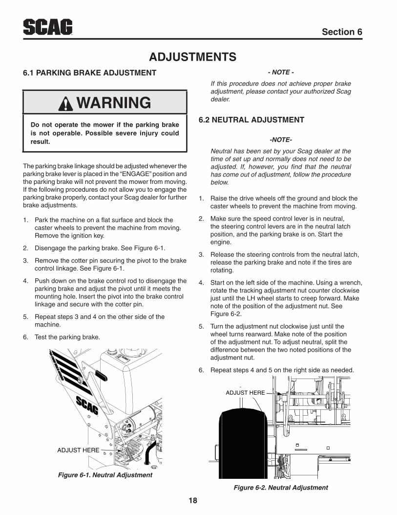
PARkING BRAkE ADJUSTMENT6.1
WARNINGDo not operate the mower if the parking brake is not operable. Possible severe injury could result.
The parking brake linkage should be adjusted whenever the parking brake lever is placed in the “ENGAGE” position and the parking brake will not prevent the mower from moving. If the following procedures do not allow you to engage the parking brake properly, contact your Scag dealer for further brake adjustments.
Park the machine on a flat surface and block the 1. caster wheels to prevent the machine from moving. Remove the ignition key.
Disengage the parking brake. See Figure 6-1.2.
Remove the cotter pin securing the pivot to the brake 3. control linkage. See Figure 6-1.
Push down on the brake control rod to disengage the 4. parking brake and adjust the pivot until it meets the mounting hole. Insert the pivot into the brake control linkage and secure with the cotter pin.
Repeat steps 3 and 4 on the other side of the 5. machine.
Test the parking brake.6.
ADJUST HERE
Neutral AdjustmentFigure 6-1.
ADJUSTMENTS- NOTE -
If this procedure does not achieve proper brake adjustment, please contact your authorized Scag dealer.
NEUTRAL ADJUSTMENT6.2
-NOTE-
Neutral has been set by your Scag dealer at the time of set up and normally does not need to be adjusted. If, however, you find that the neutral has come out of adjustment, follow the procedure below.
Raise the drive wheels off the ground and block the 1. caster wheels to prevent the machine from moving.
Make sure the speed control lever is in neutral, 2. the steering control levers are in the neutral latch position, and the parking brake is on. Start the engine.
Release the steering controls from the neutral latch, 3. release the parking brake and note if the tires are rotating.
Start on the left side of the machine. Using a wrench, 4. rotate the tracking adjustment nut counter clockwise just until the LH wheel starts to creep forward. Make note of the position of the adjustment nut. See Figure 6-2.
Turn the adjustment nut clockwise just until the 5. wheel turns rearward. Make note of the position of the adjustment nut. To adjust neutral, split the difference between the two noted positions of the adjustment nut.
Repeat steps 4 and 5 on the right side as needed.6.
ADJUST HERE
Neutral AdjustmentFigure 6-2.

19
RSection 6
NEUTRAL LATCH ADJUSTMENT6.3
-NOTE-
This adjustment is made to allow the steering control levers to be moved out of the neutral latch without engaging reverse.
Raise the drive wheels off the ground and block the 1. caster wheels to prevent the machine from moving.
Make sure the speed control lever is in neutral, 2. the steering control levers are in the neutral latch position, and the parking brake is on.
Loosen the control rod jam nuts. See Figure 6-3.3.
ADJUST HERE
LOOSEN HERE
LOOSEN HERE
Control Rod AdjustmentFigure 6-3.
Turn the steering control rod until the steering control 4. lever makes contact with the neutral latch. Hold the steering control rod and tighten the jam nuts. See Figure 6-4.
CONTACT HERE
Control Rod AdjustmentFigure 6-4.
Repeat steps 3 and 4 on the right side as needed.5.
TRACkING ADJUSTMENT6.4
-NOTE-
Before proceeding with this adjustment, be sure that the tire pressures are correct and the neutral adjustment and the steering control rod adjustment have been completed.
With the machine on a flat level surface, start the 1. engine, release the parking brake and place the speed control lever into the speed that will most often be used.
Squeeze the steering control levers and release the 2. neutral latch. Slowly release the steering control levers, allowing the machine to move forward.
WARNINGBefore attempting to make any tracking adjustments, move the speed control lever to the neutral position, place the blade engagement switch in the off position, apply the parking brake, and move the steering control levers into the neutral position.

20
R Section 6
If the machine pulls to one side, stop the mower 3. by placing the steering control levers in the neutral position. Using a wrench, turn the tracking adjustment nut on the slower side counter clockwise until the machine tracks straight.
Bring the steering control levers back to the neutral 4. lock position and check to see that the machine does not creep forward on the adjusted wheel.
If the machine creeps in neutral, you have moved out 5. of the neutral band and will have to turn the tracking adjustment nut clockwise until the machine does not creep.
Repeat steps 1 and 2. If the machine continues 6. to pull to one side, stop the mower by placing the steering control levers in the neutral position. Turn the tracking adjustment nut on the faster side clockwise until the machine tracks straight.
If tracking cannot be acheived, contact your Scag 7. servicing dealer.
THROTTLE CONTROL AND CHOkE 6.5 ADJUSTMENTS
These adjustments must be performed by your Scag dealer to ensure proper and efficient running of the engine. Should either need adjustment, contact your authorized Scag service center.
BELT ADJUSTMENT6.6
WARNINGBefore removing any guards, shut the engine off and remove the ignition key.
All drive belts are spring loaded and self-tensioning, however after the first 2, 4, 8 and 10 hours of operation, the belts should be checked for proper alignment and wear. Thereafter, check the belts after every 40 hours of operation or weekly, whichever occurs first.
WARNINGIf the pump drive belt fails, steering control will be lost which could result in serious injury or death. Replace the pump drive belt as needed or every 400 hours / 2 years, whichever occurs first.
BELT ALIGNMENT6.7
Belt alignment is important for proper performance of your Scag mower. If you experience frequent belt wear or breakage, see your authorized Scag service center for belt adjustment.
CUTTER DECk ADJUSTMENTS6.8
Cutter deck level, pitch and height are set at the factory. However, if these adjustments should ever need to be made, the following procedures will aid in obtaining the proper cutter deck adjustment.
- NOTE -
Before proceeding with the cutter deck adjustments, be sure that all tires are properly inflated.
CUTTER DECk LEvEL
The cutter deck should be level from side-to-side for proper cutting performance. To check for level, be sure that the mower is on a flat, level surface, the tires are properly inflated and the cutter deck is set at the most common cutting height that you will use. On the RH side of the machine, check the distance from the top of the cutter deck to the floor. Next check the distance from the top of the cutter deck to the floor on the LH side of the machine. Both measurements should be the same. If the two measurements are different, the cutter deck level must be adjusted as follows:
If the cutter deck is lower on one side, loosen the 1. elastic stop nuts securing the hanger chains to the cutter deck on the front and rear of the lower side. See Figure 6-5.

21
RSection 6
ADJUST HERE
Cutter Deck Level AdjustmentFigure 6-5.
Move bolts on the front and rear deck hanger chains 2. up or down in the slots until the cutter deck is level between both sides. See Figure 6-5
Hold the cutter deck in position and tighten the two (2) 3. elastic stop nuts to secure the cutter deck in the proper position.
CUTTER DECk PITCH
The pitch of the cutter deck should be equal between the front and rear of the cutter deck for proper cutting performance. To check for proper deck pitch, be sure that the mower is on a flat, level surface and the tires are properly inflated.
Check the distance from the top of the cutter deck to the floor at the rear RH side of the cutter deck directly behind the cutter deck hanging chains. Next check the distance from the top of the cutter deck to the floor at the front RH side of the cutter deck directly in front of the cutter deck hanging chains. The measurement at the front of the cutter deck should be the same as the rear of the deck. Make these measurements at the LH side of the cutter deck also. If the measurement at the front of the deck is not the same, the cutter deck pitch must be adjusted as follows:
Loosen the elastic stop nuts securing the hanger 1. chains to the front of the cutter deck. See Figure 6-6 and 6-7.
ADJUST HERE
Cutter Deck Pitch AdjustmentFigure 6-6.
Move bolts on the front hanger chains up or down in 2. the slots until the cutter deck pitch is equal between both sides. Hold the cutter deck in position and tighten the elastic stop nuts.
ADJUST HERE
Cutter Deck Pitch AdjustmentFigure 6-7.
- NOTE -
To prevent the cutter deck from teetering, all four (4) cutter deck hanging chains must have tension on them. If all four chains do not have tension on them and the deck teeters, you must readjust the cutter deck as outlined in the procedures above. All measurements should be taken from the top edge of the deck as the deck has an uneven bottom edge.

22
R Section 6
CUTTER DECk HEIGHT
The cutter deck height adjustment is made to ensure that the cutter deck is cutting at the height indicated on the cutting height index gauge. To check for proper deck height, be sure that the mower is on a flat, level surface and the tires are properly inflated.
Push the cutter deck lift lever forward, hold and 1. place the cutter deck in the 3" cutting position.
Check the measurement from the floor to the 2. cutter blade tip. If the measurement is not 3", an adjustment can be made using the slots in the cutter deck.
Loosen the elastic stop nuts securing the hanger 3. chains to the front and rear of the cutter deck on both sides. See Figure 6-8.
- NOTE -
Only the right hand side of the cutter deck is shown below.
ADJUST HERE
Cutter Deck Height AdjustmentFigure 6-8.
Move bolts on the front and rear deck hanger 4. chains up or down in the slots until the measurement at the cutter blade is 3" on both sides of the cutter deck.
Hold the cutter deck in position and tighten the 5. elastic stop nuts to secure the cutter deck in the proper position
ELECTRIC CLUTCH ADJUSTMENT6.9
The electric clutch serves two functions in the operation of the mower. In addition to starting and stopping the power flow to the cutter blades, the clutch also acts as a brake to assist in stopping blade rotation when the PTO is switched off or the operator presence circuit is interrupted.
When the clutch is disengaged, the air gap between the armature and rotor must be adjusted to fifteen thousandths of an inch, 0.015, for proper operation. The airgap adjustment is made at three bolts on the clutch. There are three inspection windows, one next to each adjusting bolt. See Figure 6-11.
INSPECTION WINDOW (x3)
Clutch Air Gap AdjustmentFigure 6-9.
Locate the inspection windows on the clutch.1.
Place a 0.015 feeler gauge in the slot between the 2. rotor and the armature. See Figure 6-10.
INSERT 0.015 FEELER GAUGE HERE
Clutch Air Gap AdjustmentFigure 6-10.
Tighten or loosen the adjusting bolt as needed to 3. acheive the 0.015 inch airgap. See Figure 6-11.Perform this operation at all three inspection windows.

23
RSection 6
ADJUSTMENT NUTS
ADJUSTMENT NUTS
Clutch Air Gap AdjustmentFigure 6-11.
This adjustment should be done every 500 hours of operation or annually, whichever comes first. In cases where the machine is heavily used, airgap settings should be checked more often.
If the air gap is too narrow, the clutch armature may drag when disengaged, resulting in premature failure.
If the air gap is too wide, the clutch may be slow to engage as the magnet must pull the armature in from a greater distance.

24
R Section 7
MAINTENANCE CHART - RECOMMENDED SERvICE INTERvALS7.1
HOURS
PROCEDURE COMMENTSBREAk-IN (FIRST 10)
8 20 40 100 200 400
X Check all hardware for tightness
XCheck a l l be l t s fo r p rope r alignment
See paragraph 7.6
XCheck all hydraulic fittings and hoses for leaks
See paragraph 2.5
X Check engine oil level See paragraph 7.3
X *Clean mower
X Check tire pressure See paragraph 7.8
X *Clean air filter element See paragraph 7.5
X Check condition of blades See paragraph 7.7
X Sharpen cutter blades See paragraph 7.7
X Check tire pressure See paragraph 7.10
XCheck the operator inter lock system
See paragraph 4.2
X Change engine oil and filter See paragraph 7.3
XCheck belts for proper alignment See paragraph 7.6
X Check condition of fuel lines
XCheck a l l be l t s fo r p rope r alignment
X*Replace engine air filter See eng ine opera to r ' s
manual
X Grease caster wheel bearings See paragraph 7.2
XDrain hydraulic system, replace hydraulic oil and filters
Use SAE 20W50 Motor Oil. See paragraph 7.2
X Check all hardware for tightness
X Change engine oil See paragraph 7.4
X *Clean air cleaner element See paragraph 7.5
MAINTENANCE

25
RSection 7
MAINTENANCE CHART - RECOMMENDED SERvICE INTERvALS (CONT'D)
HOURS
PROCEDURE COMMENTSBREAk-IN (FIRST 10)
8 40 100 200 400
X Check hardware for tightness
X Change engine oil filter See paragraph 7.4
X Replace engine fuel filter See paragraph 7.5
XGrease caster wheel pivot shafts
See paragraph 7.2
XDrain hydraulic system, replace hydraulic oil and filters
Use SAE 20W50 Motor Oil. See paragraph 7.2
X Adjust electric PTO clutch See paragraph 6.6
* Perform these maintenance procedures more frequently under extreme dusty or dirty conditions
LUBRICATION7.2
GREASE FITTING LUBRICATION CHART
LOCATION LUBRICATION INTERvAL LUBRICANTNO. OF
PLACES
1 - Caster Wheel Pivot 100 Hours / Bi-Weekly Chassis Grease 2
2 - Caster Wheel Bearings 100 Hours / Monthly Chassis Grease 2

26
R Section 7
B. CHANGING HYDRAULIC OIL
The hydraulic system oil should be changed after the first 120 hours of machine operation and every 400 hours or annually thereafter, whichever occurs first. The oil should also be changed if the color of the fluid has become black or milky. A black color and/or a rancid odor usually indicates possible overheating of the oil, and a milky color usually indicates water in the hydraulic oil.
- IMPORTANT -
The hydraulic system oil should be changed if you notice the presence of water or a rancid odor to the hydraulic oil.
Park the mower on a level surface and stop the 1. engine.
Remove the three 1/4" filter guard screws and filter 2. guard from both axles. See Figure 7-2. Clean any loose debris around the perimeter of the filter.
REMOVE SCREWS ANDOIL FILTER GAURD
REMOVE OILFILTER
Hydraulic Oil Filter and Drain PlugFigure 7-2.
Place a suitable container under the hydraulic 3. oil filters. Remove the fill cap from the expansion reservoir.
HYDRAULIC SYSTEM7.3
A. CHECkING HYDRAULIC OIL LEvEL
The hydraulic oil level should be checked after the first 10 hours of operation. Thereafter, check the oil after every 200 hours of machine operation or monthly, whichever occurs first.
- IMPORTANT -
If the oil level is consistently low, check for leaks and correct immediately.
Wipe dirt and contaminants from around the 1. reservoir cap. Remove the cap from the hydraulic oil expansion reservoir.
When the machine is "cold" (before operation), 2. visually check the level of the hydraulic system oil. Hydraulic system oil level should be up to the FULL / COLD indicator line on the hydraulic expansion reservoir. See Figure 7-1. DO NOT overfill; (overfilling the oil reservoir may cause oil seepage).
Clean the fill cap and install it onto the expansion 3. reservoir.
HYDRAULIC SYSTEM OILEXPANSION RESERVOIR
FULL / COLDINDICATOR LINE
Hydraulic System Oil LevelFigure 7-1.

27
RSection 7
The hydraulic system will need to be purged of 10. all air. Raise the rear of the machine so the drive wheels are off the ground. Use jackstands and block the front caster wheels to prevent the machine from moving.
Move the dump valve control levers to the 11. "freewheel" position. See Figure 7-4.
DUMP VALVECONTROL LEVER
DUMP VALVECONTROL LEVER
"FREEWHEEL" POSITION
"FREEWHEEL" POSITION
Dump Valve Control LeverFigure 7-4.
While in the operator's position, start the engine, 12. disengage the parking brake, select the desired speed using the speed control lever, release the neutral latch for both sides and slowly release both the left and right steering control levers.
Run the engine at 1/2 throttle and move the steering 13. control levers to full forward and reverse 5 to 6 times.
Move the speed control lever to the neutral position, 14. engage the neutral latch for both sides and engage the parking brake. Move the dump valve comtrol levers to the "drive" position. See Figure 7-4.
While in the operator's position, start the engine, 15. disengage the parking brake, select the desired speed using the speed control lever, release the neutral latch for both sides and slowly release both the left and right steering control levers. It may be necessary to repeat steps 11 to 15 until the air is completely purged from the system.
Check the hydraulic system oil level as explained in 16. Section 7.2.
Remove the hydraulic filters from both axles and 4. allow the fluid to drain into the container. Properly discard the oil when the system has drained completely. See Figure 7-2.
Once the hydraulic system has drained, install new 5. hydraulic oil filters to both axles by hand, turn 3/4 to one complete turn after filter gasket contacts the filter base.
Reinstall the filter guards and torque the screws to 6. 65 in/lbs.
Remove the top port plug from both axles before 7. filling with oil. See Figure 7-3.
REMOVE TOPPORT PLUG
Top Port Plug LocationFigure 7-3.
Fill the hydraulic expansion reservoir with 20w50 8. motor oil until the oil just appears at the bottom of each axle top port. Approximately 5 quart capacity. Reinstall the top port plugs and torque to 180 in/lbs.
-NOTE-
The left side axle will fill with oil first using approximately 4 quarts of oil. Reinstall the top port plug in the left axle and continue to fill the hydraulic system through the expansion reservoir. The right side axle should fill up to the bottom on the top port plug after adding an additional one quart of oil. Reinstall the top port plug on the right axle and fill the hydraulic expansion reservoir to the proper level as explained in Section 7.2.
Reinstall the hydraulic expansion reservoir cap.9.

28
R Section 7
ENGINE OIL7.4
A. CHECkING ENGINE CRANkCASE OIL LEvEL
The engine oil level should be checked after every 8 hours of operation or daily as instructed in the Engine Operator’s Manual furnished with this mower.
B. CHANGING ENGINE CRANkCASE OIL
After the first 20 hours of operation, change the engine crankcase oil and replace the oil filter. Thereafter, change the engine crankcase oil after every 100 hours of operation or bi-weekly, whichever occurs first. Refer to the Engine Operator’s Manual furnished with this mower for instructions.
C. CHANGING ENGINE OIL FILTER
After the first 20 hours of operation, replace the engine oil filter. Thereafter, replace the oil filter after every 200 hours of operation or every month, whichever occurs first. Refer to Engine Operator’s Manual for instructions.
ENGINE FUEL SYSTEM7.5
DANGERTo avoid injury from burns, allow the mower to cool before removing the fuel tank cap and refueling.
A. FILLING THE FUEL TANk
Fill to the bottom of the filler neck insert (approximately 5-1/2 gallons indicating Full (F) on the fuel gauge) at the beginning of each operating day. See Figure 7-5. Do not overfill. Use clean, fresh unleaded gasoline with a minimum octane rating of 87 and a maximum of 10% Ethanol.
DO NOT use E85 Fuel. Using E85 Fuel will cause severe damage to the engine.
E F
1/4
1/2
3/4
. ...
.
FUEL LEVEL
FILLER NECK INSERT
C.A.R.B. / EPA Phase 3 Fuel LevelFigure 7-5.
To avoid personal injury or property damage, use extreme care in handling gasoline. Gasoline is extremely flammable and the vapors are explosive.
Extinguish all cigarettes, cigars, pipes and other 1. sources of ignition.
Use only an approved gasoline container.2.
Never remove the gas cap or add fuel with the 3. engine running. Allow the engine to completely cool before fueling.
Never fuel the machine indoors or in an enclosed 4. trailer.
Never store the machine or fuel container where 5. there is an open flame, spark or pilot light such as on a water heater or other appliances.
Never fill containers inside a vehicle or on a truck 6. or trailer bed with a plastic liner. Always place containers on the ground away from your vehicle before filling.
Remove the machine from the truck or trailer and 7. fuel on level ground. If this is not possible, then refuel the machine with a portable container, rather than from a gasoline dispenser nozzle.
Keep the nozzle in contact with the rim of fuel tank 8. or container opening at all times until fueling is complete. Do not use a nozzle lock-open device.
If fuel is spilled on clothing, change clothing 9. immediately and wash affected skin.

29
RSection 7
Replace gas cap and tighten the fuel cap until it 10. ratchets.
B. REPLACING IN-LINE FUEL FILTER ELEMENTS
The engine fuel filter should be replaced after every 500 hours of operation or annually, whichever occurs first.
Close the shut-off valve.1.
Remove and replace the engine fuel filter. Open the 2. fuel shut-off valve.
ENGINE AIR CLEANER7.6
A. CLEANING AND/OR REPLACING AIR CLEANER ELEMENT
For any air cleaner, the operating environment dictates the air cleaner service periods. Inspect and clean the air cleaner element after every 100 hours of operation or bi-weekly, whichever occurs first and replace the element if required.
- NOTE -
In extremely dusty conditions it may be necessary to check the element once or twice daily to prevent engine damage.
Remove the air cleaner cover. Set aside.1.
Remove the air cleaner and inspect.2.
Clean or replace the air cleaner and foam 3. pre-cleaner as recommended by the engine manufacturer.
Replace the air cleaner cover and secure.4.
CUTTER BLADES7.7
A. BLADE INSPECTION
Remove the ignition key before servicing the blades.1.
WARNINGAlways wear proper hand and eye protection when working with cutter blades.
Check the cutter blades for straightness. If the cutter 2. blades appear bent, they will need to be replaced.
Check the cutter blades for wear. If any part of the 3. cutter blade is worn to 1/2 its original thickness, replace the cutter blade.
WARNINGDo not attempt to straighten a bent blade, and never weld a broken or cracked blade. Always replace it with a new blade to assure safety.
Check the cutter blades for gouges. If there are 4. gouges on the top or bottom surfaces of the cutter blade, replace the cutter blade.
If a blade cutting edge is dull or nicked, it should be 5. sharpened. Remove the blades for sharpening. See "Blade Replacement."
- NOTE -
Keep the blades sharp. Cutting with dull blades not only yields a poor mowing job, but slows the cutting speed of the mower and causes extra wear on the engine and the blade drive by pulling hard.
B. BLADE SHARPENING
- NOTE -
If possible, use a file to sharpen the blade. Using a wheel grinder may burn the blade.
- NOTE -
DO NOT sharpen the blades beyond 1/3 of the width of the blade. See Figure 7-6.
Sharpen the cutting edge at the same bevel as the 1. original. See Figure 7-6. Sharpen only the top of the cutting edge to maintain sharpness.

30
R Section 7
SGB033
Angle Blade Back
Do Not Cut In
X Must NOT Exceed1/3 Blade Width
X
30
Blade SharpeningFigure 7-6.
Check the balance of the blade. If the blades are out 2. of balance, vibration and premature wear can occur. The cutter blades should be balanced to 1-1/2 oz-in. See your authorized Scag dealer for blade balancing or special tools, if you choose to balance your own blades.
C. BLADE REPLACEMENT
WARNINGAlways wear proper hand and eye protection when working with cutter blades.
Remove the ignition key before replacing the blades.1.
Raise the mower deck to the highest position. Place 2. the lanyard pin in the highest cutting height position to prevent the cutter deck from falling.
Secure the cutter blades to prevent them from 3. rotating, (use the optional Blade Buddy tool P/N 9212, to assist in securing the cutter blades), remove the blade attaching bolt. Remove the cutter blade, bolt, lockwasher and flatwasher from the spindle shaft. See Figure 7-7.
CAUTIONInspect the cutter blade spacer(s) and washer for wear and/or cupping. Replace the worn parts. Worn spacer(s) and/or washer will not allow proper tightening of the cutter blade and can lead to cutter blade failure, personal injury or property damage.
To install the new cutter blade, put the lockwasher 4. and flatwasher onto the blade bolt and slide the bolt into the hole in the cutter blade.
5/8-11 x 1-1/2" HEX HEAD BOLTTORQUE TO 75 FT/LBS
LOCKWASHER
FLATWASHER
CUTTER BLADE
Blade ReplacementFigure 7-7.
- NOTE -
Be sure that the blade is installed with the lift wing toward the top.
Install the cutter blade onto the cutter spindle shaft. 5. Secure the blades from rotating and torque to 75 ft/lbs. See Figure 7-7.
TIRES7.8
Check the tire pressures after every 8 hours of operation or daily.
Caster Wheels Flat Free Drive Wheels 12 PSI

31
RSection 8
SCAG APPROvED ATTACHMENTS AND ACCESSORIES.8.1
Attachments and accessories manufactured by companies other than Scag Power Equipment are not approved for use on this machine.
Scag approved attachments and accessories:
Mulch Plate (p/n 920G, 9298)•
Hurricane Mulch (p/n 920D, 9293)•
GC-F4 (p/n 9075)•
Blade Buddy (p/n 9212)•
Hour Meter (p/n 484565)•
ILLUSTRATED PARTS LIST

32
R Section 8
36" CUTTER DECk
2014 SWZT 36CD
31
32
33
34
32
35
36
12
34
5 5
66 7
9
9
8
1011
12
1315
1
46
12
19
18
18
20 21
26
2523
23
24
2928
17
116
1445
45
44
43
42
27
41
4037
38
39
30
22

33
RSection 8
36" CUTTER DECk
Ref. No.
Part No. DescriptionRef. No.
Part No. Description
12345678910111213**141516171819202122
04021-0942461504043-0442436704112-0604063-0148461948385148332404001-15448224504021-1046203146247242587204030-0304001-1204021-2204043-04483453-034621904370804001-62462571
Nut, Elastic Stop 3/8-16Bracket, Belt GuideFlatwasher, 3/8-.391 x .938 x .105Dust ShieldNut, 3/4-16 Spiral LockKey, 1/4 x 1/4 x 1-1/4"Belt, Cutter DeckPulley, 5" IdlerPulley, 5.73" OD - 25mm BoreBolt, Hex Head 5/16-18 x 4-3/4"Spring, Discharge ChuteNut, Elastic Stop 5/16-18Discharge Chute AssemblyCA Discharge ChuteTurbo BaffleLockwasher, 5/16 SpringBolt, Hex Head 5/16-18 x 1-3/4"Nut, Elastic Stop 5/16-18Flatwasher, 3/8-.391 x .938 x .105 HardenedBearing, PlasticIdler Arm (incl. item #18)Pivot, IdlerBolt, Hex Head 3/8-16 x 3-1/4"Cutter Deck w/Decals, SMWZT-36
232425262728293031323334353637383940414243444546
04019-0604001-4642595904001-7204041-384833794370346195048330448330343693462014436944369504043-0604030-0704001-12148287804001-17504001-5104001-13648337504019-0404041-11
Nut, Serrated Flange 1/2-13Bolt, Hex Head 3/8-16 x 2-1/4"Pusharm Bolt, Hex Head 1/2-13 x 2"Flatwasher, 3/8-.406 x 2.25" x .188BearingSpacer, BearingSpindle AssemblyDebris ShieldBearingSpacer, BearingSpindle Housing Assembly (incl. item #32, 33)Protector, BearingShaft, SpindleFlatwasher, 5/8-11 x 1-1/2"Lockwasher, 1/2 SpringBolt, Hex Head 5/8-11 x 1-1/2"Cutter Blade, 18"Bolt, Hex Head 5/16-18 x 1-1/2" Gr.8Bolt, Hex Head 3/8-16 x 3-3/4"Bolt, Hex Head 3/8-16 x 1-1/2" Gr.8Spring, IdlerNut, Serrated Flange 3/8-16Flatwasher, 3/8-.406 x 1-1/2"
* = California Models Only (not shown)

34
R Section 8
48" CUTTER DECk
36
37
38
39
37
40
41
2014 SWZT CD - Rev 1
35
32
33
34
31
30
29
2542
4746
6
4344
44
45
1
48
49
51
50
29
52
1920
22
18
15
16
1
14
15
21
22
2324
9
9
11
10 12
3
4
10
5
67
61
8
2
3
4
1
6
7
3
4
10
17
13
27
2653
28
55 56
54

35
RSection 8
Ref. No.
Part No. DescriptionRef. No.
Part No. Description
123456789101112131415161718192021**222324252627
04021-0942461504112-0604063-0148461804043-044243674838514259784833234371148342204001-1204041-11483453-034621914370804001-6204110-04481625-0146203146247242561904021-1048224504001-15446265504041-3804001-51
Nut, Elastic Stop 3/8-16Bracket, Belt GuideNut, 3/4-16 Spiral LockKey, 1/4 x 1/4 x 1-1/4"Belt, Cutter DeckFlatwasher, 3/8-.391 x .938 x .105Dust ShieldPulley, 5" IdlerBelt CoverPulley, 5.13" OD - 25mm BoreSpacerPulley, 5" IdlerBolt, Hex Head 5/16-18 x 1-3/4"Flatwasher, 3/8-.406 x 1-1/2"BearingIdler Arm (incl. item #15)Pivot, IdlerBolt, Hex Head 3/8-16 x 3-1/4"U-Nut, 3/8-16Knob w/StudDischarge Chute AssemblyCA Discharge ChuteTurbo BaffleNut, Elastic Stop 5/16-18Spring, Discharge ChuteBolt, Hex Head 5/16-18 x 4-3/4"Cutter Deck w/Decals, SMWZT-48Flatwasher, 3/8-.406 x 2.25" x .188Bolt, Hex Head 3/8-16 x 3-3/4"
2829303132333435363738394041424344454647484950515253545556
04001-7704019-0404001-17548287704043-0604030-0704001-12146195048330448330343693462014436944369504001-7242595904019-0604001-464833794370304021-2204030-034306304001-13648337548229504019-0346192604001-09
Bolt, Hex Head 3/8-16 x 3-1/2"Nut, Serrated Flange 3/8-16Bolt, Hex Head 5/16-18 x 1-1/2" Gr.8Cutter Blade, 16-1/2"Flatwasher, 5/8-.688 x 1.75 x .134 HDLockwasher, 1/2 SpringBolt, Hex Head 5/8-11 x 1-1/2"Spindle AssemblyDebris ShieldBearingSpacerSpindle Housing Assembly (Incl. item #37, 38)Protector, BearingShaft, SpindleBolt, Hex Head 1/2-13 x 2"PusharmNut, Serrated Flange 1/2-13Bolt, Hex Head 3/8-16 x 2-1/4"BearingSpacer, BearingNut, Elastic Stop 5/16-18Lockwasher, 5/16 SpringSpacerBolt, Hex Head 3/8-16 x 1-1/2 Gr.8Spring, IdlerWheel, Anti-ScalpNut, Serrated Flange 5/16-18Shaft WeldmentBolt, Hex Head 5/16-18 x 1"
48" CUTTER DECk
* = California Models Only (not shown)

36
R Section 8
CUTTER DECk CONTROLS
A
A
1
2
3
45
67
8
9
10
10
1314
1211
10
9
1211
17
6
7
165
15
9
38
36
3738
10 18
19
2014
13 5 21
20
10
9
22
21
9
10
510
22
9
23
24
23
34
25
2726
26
29
30
31 32
34
33 35
10
28

37
RSection 8
CUTTER DECk CONTROLS
Ref. No. Part No. Description
1234567891011121314151617181920212223242526272829303132333435363738
481625-0104029-0446256546252204021-0904041-074308648466904001-2004019-0448333442520904017-1704021-0445201842596846257004062-0448334504001-3104041-074854048114-0404003-23927548177048176948114-0304021-07450064302204001-3704066-0148100-0104024-0204110-0342597043805
Knob W/Stud, 3/8-16 x 1-1/4"Wing Nut, 3/8" Plastic SmallBelt Cover w/DecalsDeck Bellcrank Assy. (Incl. item #8)Nut, Elastic Stop 3/8-16Flatwasher, 3/8-.391 x .938 x .105BushingGrip, Deck LiftBolt, Hex Head 3/8-16 x 1-1/2"Nut, Serrated Flange 3/8-16Bearing, Deck LiftReinforcement, BearingCpscrw, 5/16-18 x 1"Serrated Flange Hex HeadNut, Center Lock 5/16-18Deck Lift Weldment, FrontLink, DeckliftFrame w/DecalsHair Pin CotterPin Assembly w/LanyardBolt, Hex Head 3/8-16 x 2-1/2"Flatwasher, 3/8-.391 x .938 x .105ChainGrease FittingBolt, Carriage 3/8-16 x 1"Flat-Free Tire Assy. (Incl. #26, #27, #28)Retainer, Caster Wheel BearingRoller Bearing, Caster WheelGrease Fitting, 45 Degree 1/4-28Nut, Elastic Stop 1/2-13Caster YokeSleeve, Caster Wheel BearingBolt, Hex Head 1/2-13 x 5-1/2"Quick PinBronze BearingNut, Push-On 3/8"U-Nut 3/8-16Bracket, Deck HeightSpacer

38
R Section 8
ENGINE DECk & HYDRAULIC SYSTEM
A
A
B
B
1
2
3
4
5
6
4
7
8
9
11
12
13
1415
16
16
17
10
19
18
8
21
20
23
60
25
26
14
27
28
2930
31
32
33
343536
3637
41
43
42
38
39
40
58
59
44
45
44
49
46
47
48
55
51
52
50
5354
33 55
56
55
57
722
24
61

39
RSection 8
ENGINE DECk & HYDRAULIC SYSTEM
Ref. No.
Part No. DescriptionRef. No.
Part No. Description
1
2345678910111213141516171819202122232425262728293031
*485014*48501504001-5443715483453-0446212248308704021-0504019-0404063-0304003-0248462048351448343804017-0548466448136-1348466348136-0504001-19604003-044328204110-0104021-0804003-1204019-0242592342592242577804017-1604019-0304001-49
Engine, Kawasaki FS481VEngine, Kawasaki FS541VBolt, Hex Head 3/8-16 x 3"Pivot, IdlerBearingIdler Arm (incl. item #4)Spring, Transmission IdlerNut, Center Lock 3/8-16Nut, Serrated Flange 3/8-16Key, 1/4 x 1/4 x 2-1/2"Bolt, Carriage 1/4-20 x 3/4"Muffler, Kawasaki FS/FXCapReservoir Assembly (incl item #12)Bolt, Hex Head, Serrated Flng 1/4-20 x 3/4"Hose, RH TransmissionClamp, 0.69" Max Dia.Hose, LH TransmissionClamp, 0.87" Max Dia.Bolt, Hex Head 5/16-18 x 6-1/2"Bolt, Carriage 5/16-18 x 1"SpacerU-Nut, 1/4-20Nut, Elastic Stop 1/4-20Bolt, Carriage 5/16-18 x 3/4Nut, Serrated Flange 1/4-20Fan Cover, RHFan Cover, LHSkid PlateCpscrw, 5/16-18 x 3/4"Serrated Flange HHNut, Serrated Flange 5/16-18Bolt, Hex Head 5/16-18 x 3"
323334353637383940414243444546474849505152535455565758
596061
04001-13504043-0404021-0943720482800-044388048457848363848457648457748459542595404061-0104040-1448207004069-01438764418846201204041-2804102-0604030-0504001-5104021-1042595342569648468248187148186748186904028-0204024-03484600
Bolt, Hex Head 3/8-16 x 1-3/4"Flatwasher, 3/8-.391 x .938 x .105 HardenedNut, Elastic Stop 3/8-16SpacerFitting, TransmissionSpacer, AxleBelt, Transmission DrivePulley, 3-1/2" Dia.**Transaxle Assy., (ZH-GMCC-3LUB-1MXX)**Transaxle Assy., (ZH-KMCC-3LUC-1MXX)Pulley, 4-1/2" Dia. 1" BorePusharm Mount Bracket, RHCotter Pin, 3/32 x 1"Flatwasher, 1/4-.312 x .750 x .065Spring, Dump Valve LinkPin, Rue Cotter 3/8" Dia.Joint, SwivelLink, Dump ValveElectric Clutch AssemblyFlatwasher, 7/16-.469 x 1.75 x .25Bolt, Hex Head 7/16-20 x 3" w/t PatchLockwasher, 7/16" springBolt, Hex Head 3/8-16 x 3-3/4"Nut, Elastic Stop 5/16-18Pusharm Mount Bracket, LHBracket, Anti-RotationWheel Assembly 18 x 6.5-8 (36" Only)Tire 18 x 6.5-8 (36" Only)Wheel Assembly 18 x 8.5-8 (48" Only)Tire 18 x 8.5-8 (48" Only)Wheel Nut, 1/2-20Nut, Push-On 5/16-18Spring, RTN
* Available through the individual engine manufacturer. ** RTN Spring is Scag p/n 484600. See item #61

40
R Section 8
STEERING CONTROLS
A
A
B
B
1
1
1
11
1
2
3
45
3
109
8
6
7
4
529
47
53
26
45
46
6
23
44
43 4245
26
48
41
23
40
49
5150
35
34
26
1
39
38
25
36
35
37
3633
30
32
30
31
29
1127
13
12
26
14
15
166
17
22 28
18
19
20
21
22
24
2523
6

41
RSection 8
STEERING CONTROLS
Ref. No.
Part No. DescriptionRef. No.
Part No. Description
12345678910111213141516171819202122232425262728
04021-094845894367448403545236304040-0504001-7704019-024871742593746257404010-3348460948474904032-0504009-1148360146257548467245211804019-03483453-1904001-2004003-0904001-1204021-1004021-0104009-14
Nut, Elastic Stop 3/8-16Linkage, Speed ControlSpacerBearingNeutral Plate WeldmentFlatwasher, 3/8-.406 x .812 x .065Bolt, Hex Head 3/8-16 x 3-1/2"Nut, Serrated Flange 1/4-20SwitchBracket, Operator Presence SwitchHandle Assy, W/DecalsMachine Screw, #10-32 x 1-1/4", Pan HeadLatch, ThumbPlate, Anti-FrictionWasher, 1/4" Curved SpringBolt, Shoulder 3/8 x 1"Spring, Speed ControlNeutral Handle Assy (incl item #22)Knob, Soft TouchHandle Weldment, Speed ControlNut, Serrated Flange 5/16-18Bearing, Plastic 1/2" I.D.Bolt, Hex Head 3/8-16 x 1-1/2"Bolt, Carriage 1/4-20 x 1-1/4"Bolt, Hex Head 5/16-18 x 1-3/4"Nut, Elastic Stop 5/16-18Nut, Elastic Stop #10-32Bolt, Shoulder 3/8 x .375"
293031323334
353637
38394041424344454647
484950515253
04021-0804040-1542594804009-16484670462494462495483453-224386646248946249004001-2148457904017-1642575604001-4504030-0404041-07487964835744523004523014376604001-0904050-01484671-0104003-0204043-04
Nut, Elastic Stop 1/4-20Flatwasher, 5/16-.375 x .875 x .083Bracket, Neutral SwitchBolt, Shoulder 1/2 x 2"Spring, Operator PresenceHandle, Op. Presence-LH (incl item #35)Handle, Op. Presence-RH (incl item #35)BearingSleeve, PivotHandle Assembly-LH (incl item #35)Handle Assembly-RH (incl item #35)Bolt, Hex Head 3/8-16 x 1-3/4"Linkage, SteeringCpscrw, 5/16-18 x 3/4"Serrated Flange HHBracket, Transaxle ControlBolt, Hex Head 3/8-16 x 2"Lockwasher, 3/8” SpringFlatwasher, 3/8-.391 x .938 x .105Bearing, Self Aligning 5/8” I.D.Linkage, PumpWeldment, Bellcrank-LHWeldment, Bellcrank-RHSpacer, AxlesBolt, Hex Head 5/16-18 x 1"Retaining Ring .625" EXT. "E"BearingBolt, Carriage 1/4-20 x 3/4"Flatwasher, 3/8-.391 x .938 x .105 Hardened

42
R Section 8
BRAkE COMPONENTS
A
A
18
1
2
3
5
76
4
89
10
11
12
13
14
1
15
16
1
1312
4
6
17
19

43
RSection 8
BRAkE COMPONENTS
Ref. No. Part No. Description
12345678910111213141516171819
04069-0146251548154804062-024418704017-1604061-0204040-054375148417504021-1804021-1048796452358437264416504050-01483453-1804017-27
Pin, Rue Cotter 3/8" Dia.Brake Lever w/GripGrip, Brake LeverHair Pin, .080 x 1.19"Rod, Brake LinkageCpscrw, 5/16-18 x 3/4"Serrated Flange HHCotter Pin, 3/32 x 3/4"Flatwasher, 3/8-.406 x .812 x .065Bushing, Pivot SlideSpring, BrakeNut, Elastic Stop 3/8-24Nut, Elastic Stop 5/16-18Bearing, Self Aligning 5/8” I.D.Weldment, Brake BellcrankJoint, SwivelRod, Brake AdjustmentRing, Retaining 5/8” External “E”BearingCpscrw, 3/8-16 x 1"Serrated Flange HH

44
R Section 8
ELECTRICAL SYSTEM AND THROTTLE CONTROL
SC
AG
PO
WE
R E
QU
IPM
EN
T
1
26
3
4
5
7
11
8
10
9
13
12
14
20
15
31
14
13
1214
1521
22
23
26
24
25
27
28
29
30
16
19
17
18

45
RSection 8
Ref. No. Part No. Description
1
2345678910111213141516171819202122232425262728293031
46206948360948017-0448017-0346257604003-4304003-124839574846654860904021-2648355204019-024259374871704003-0204019-0342594804040-1504021-0848347348462504002-1704031-0348395804063-0348459546201204041-2804030-0504102-0604003-09
Key Assembly w/FobKey w/ShroudNut, 5/8-32 SpecialLockwasher, 5/8" Internal ToothInstrument Panel w/DecalBolt, Carriage #10-24 x 1/2"Bolt, Carriage 5/16-18 x 3/4"PTO SwitchThrottle CableKey SwitchNut, Elastic Stop #10-24Choke ControlNut, Serrated Flange 1/4-20Bracket, Operator Presence SwitchSwitchBolt, Carriage 1/4-20 x 3/4"Nut, Serrated Flange 5/16-18Bracket, Neutral SwitchFlatwasher, 5/16-.375 x .875 x .083Nut, Elastic Stop 1/4-20Switch, Brake InterlockWire HarnessBolt, Hex Head M8-1.25 x 14Lockwasher, 5/16" External ToothDiodeKey, 1/4 x 1/4 x 2-1/2"Pulley, 4-1/2" Dia. 1" BoreElectric Clutch AssemblyFlatwasher, 7/16-.469 x 1.75 x .25Lockwasher, 7/16" springBolt, Hex Head 7/16-20 x 3" w/t PatchBolt, Carriage 1/4-20 x 1-1/4"
ELECTRICAL SYSTEM AND THROTTLE CONTROL

46
R Section 8
SWzT FUEL SYSTEM
To Fuel Pump
To Engine Purge Port
A
B
Tank
Purge
AB
3
2
1
4
56
78
*9*10
*10
*11
1312
12
1223
24
25
26
1819
17
1920
21
2212
13
14
1516
28
15
29
27
28
15
16
30

47
RSection 8
SWzT FUEL SYSTEM
Ref. No. Part No. Description
1
23456789101112131415161718192021222324252627282930
48428648429748425948424246237548257148374748059-01483617***48059-0548434548030-2204030-0304001-0848428548433348059-02484347484279-01484343-0148428748136-1745217604019-0348030-0904040-1504001-0904003-12
Fuel Cap w/ TetherFuel Cap w/ Tether - California Models Only (not shown)Fuel Gauge Assembly (incl. #3)Seal, Fuel GaugeFuel Tank Assembly (incl. #2, 3, 5, 6, 17, 18)Bushing, .56 Dia. VitonBall Valve w/ScreenClamp, Fuel HoseFuel Hose, 1/4" ID (order by inch)Fuel FilterClamp, Fuel HoseFuel HoseClamp, Vapor Recovery Hose 3/16"Hose, Vapor Recovery 3/16" (order by inch)Clamp, 3/8"Lockwasher, 5/16" SpringBolt, Hex Head 5/16-18 x 3/4"Grommet, VitonFitting, Remote VentClamp, Fuel Hose 7/32" IDHose, Vapor Recovery 1/4" (order by inch)Tube, Fuel Tank Insert - 4"Mender, 1/4 x 3/16 w/.02 HoleCarbon CanisterClampBracket, Canister MountingNut, Serrated Flange 5/16-18Clamp, 1/2"Flatwasher, 5/16-.375 x .875 x .083Bolt, Hex Head 5/16-18 x 1"Bolt, Carriage 5/16-18 X 3/4"
* = Available through engine manufacturer only.

48
R Section 8
zT-2800 HYDRAULIC AXLE ASSEMBLY
Overhaul Seal K
it
1
3
2
6
54
7 4
10
98
11
121314
15
1617
1819
20
24
23
21
22
25
26
27
2829
30
3132
33
34
3536
37
41
4243
38
40
4544
3946
49
48
50
5152
57
58
59
60
62
63
64
65
66
61
56
55
54
51
53
47

49
RSection 8
zT-2800 HYDRAULIC AXLE ASSEMBLY
Ref. No.
Part No. DescriptionRef. No.
Part No. Description
12
3
4567891011
1213141516171819202122232425262728293031323334
HG53246HG9005110-
5600HG71574*HG71572**HG50132HG51083HG52583HG52148HG44121HG53336HG52108HG71421*HG71413**482800-04HG51626HG51628HG52136HG51627HG51629HG51630HG51161HG72124HG51244HG53821HG53804HG50329HG50951HG71442HG71569HG53656HG53514HG53699HG71446HG50863HG53501HG50859
Bolt, Hex Head 1/4-20 x 1-1/8"Plug, 9/16-18
Kit, Side Cover *Kit, Side Cover **Washer, .5 x 1.0 x .03Jackshaft PinGear, 11TGear, 43TBearing, Ball .75 x 40 x 12Spacer, .75 x 1.32 x .257Gear, 54TKit, Housing *Kit, Housing **Fitting, TransmissionSeal, Lip .375 x .75 x .25Ring, .Retaining .375 ExternalRod, By-PassRing, Retaining .750 InternalArm, By-PassRing, .Retaining .375 ExternalSeal, Lip 17 x 40 x 7Kit, Fan & PulleyNut, Hex Locking 1/2-20FanPulleyRing, Retaining 2.06 InternalWasher, 1.23 x 1.56 x .04Kit, Shaft, InputKit, Shaft, AxleBearing, Ball 1.0 x 52 x 15 OpenSpacer, 1.355 x 2.035 x .021Seal, Lip TC4 1.0 x 2.06 x .38Hub KitNut, Hex LockingCap, AxleRing, Retaining 2.06 Internal
35363738
3940
4142434445
464748
495051525354555657585960
616263646566
HG52027HG53973HG51950HG71594*HG71589**484600HG51842*HG51841**HG51616HG44130HG52527HG51140HG72432*HG72431**HG52114HG71410HG53644*HG53655**HG72274HG50752HG51804HG52766HG53539HG51048HG50551HG70723HG51462HG71579HG71436HG72412*HG72413**HG52137HG52150HG51069HG44145HG52149HG44371
Clip, RetainingHandle, BrakeWasher, .343 x 1.5 x .062Kit, RTN Assembly *Kit, RTN Assembly **Spring, RTNArm, Control *Arm, Control **Bolt, 5/16-24 x 7/8" PatchWasher, .34 x .88 x .06Spacer, .320 x 1.005 x .150Seal, Lip 12 x 32 x 7Arm, Neutral *Arm, Neutral **FilterSeal KitFilter Guard *Filter Guard **Kit, Charge PumpBolt, 1/4-20 x 3/4"O-RingPawl, BrakeShaft, BrakeTrunnion SwashplateThrust BearingKit, Cylinder BlockThrust BearingKit, Motor Cylinder BlockKit, Charge ReliefKit, Center Section *Kit, Center Section **Bolt, Hex Head 3/8-16 x 1-1/2" PatchShaft, MotorWasher, .72 x 1.16 x .04Ring, RetainingGear, 16TWasher, .63 x 1.0 x .05
- NOTE -Refer to label on transaxle for identification
*ZH-KMCC-3LUC-1MXX
**ZH-GMCC-3LUB-1MXX
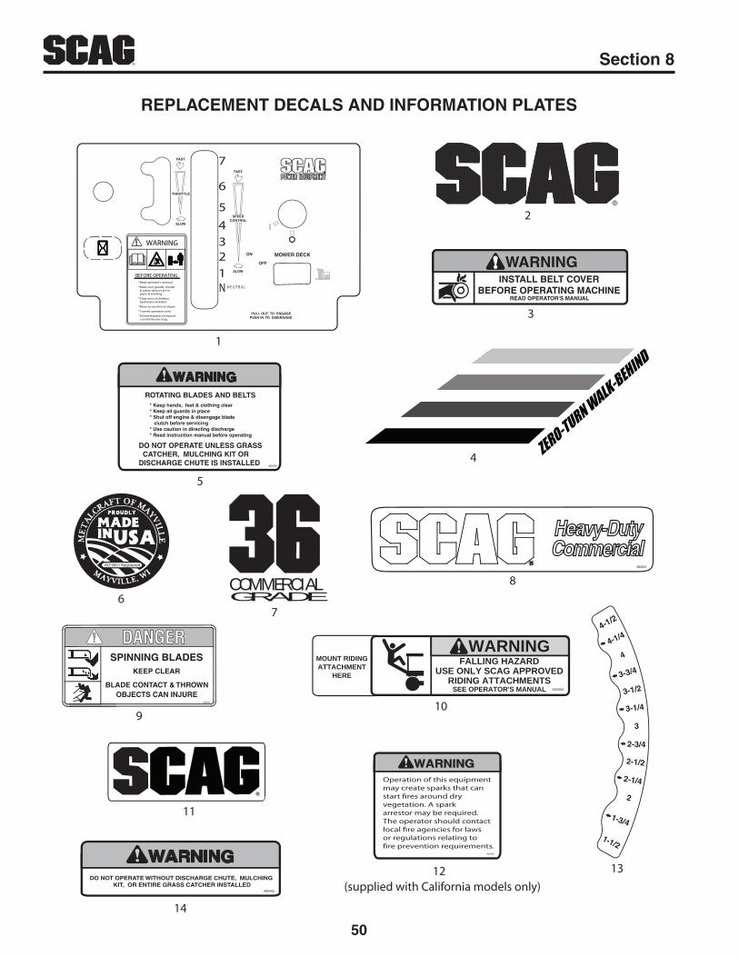
50
R Section 8
REPLACEMENT DECALS AND INFORMATION PLATES
4
BEFORE OPERATING
WARNING
*Read operator's manual
*Make sure guards, shields & safety devices are in place & working
*Clear area of children, bystanders & debris
*Mow across face of slopes
*Trained operators only
*Solicite etiquetas en espanol a un distribuidor Scag
OFF
MOWER DECK
PULL OUT TO ENGAGE PUSH IN TO DISENGAGE
ON
FAST
SLOW
SPEEDCONTROL
FAST
SLOW
THROTTLE
1234
5
6
7
N N E U T R A L
1
2
R
11
WARNING
READ OPERATOR'S MANUAL
INSTALL BELT COVERBEFORE OPERATING MACHINE
3
ISO 9001 Registered
6
WARNINGFALLING HAZARD
USE ONLY SCAG APPROVEDRIDING ATTACHMENTS
SEE OPERATOR'S MANUAL 483404
MOUNT RIDINGATTACHMENT
HERE
10
Heavy-DutyCommercial
484453
8
3-1/4
4-1/2
3-1/2
3
3-3/4
4
4-1/4
2-3/4
2-1/2
2-1/4
2
1-3/4
1-1/2
13
COMMERCIALGRADE
7
5
WARNING
* Keep hands, feet & clothing clear* Keep all guards in place* Shut off engine & disengage blade clutch before servicing* Use caution in directing discharge* Read instruction manual before operating
ROTATING BLADES AND BELTS
DO NOT OPERATE UNLESS GRASS CATCHER, MULCHING KIT ORDISCHARGE CHUTE IS INSTALLED 483406
9
SPINNING BLADESKEEP CLEAR
BLADE CONTACT & THROWNOBJECTS CAN INJURE
483505
WARNINGOperation of this equipmentmay create sparks that canstart �res around dry vegetation. A spark arrestor may be required.The operator should contact local �re agencies for laws or regulations relating to�re prevention requirements.
483900
(supplied with California models only)12
WARNINGDO NOT OPERATE WITHOUT DISCHARGE CHUTE, MULCHING
KIT, OR ENTIRE GRASS CATCHER INSTALLED483405
14

51
RSection 8
REPLACEMENT DECALS AND INFORMATION PLATES
Ref. No. Part No. Description
1234
567
891011121314*
4846624831448340248467348467448340648404483710483494484453483505483404483727483900484661483405461986
Decal, Instrument PanelDecal, Scag LogoDecal, Belt CoverDecal, Handle - LHDecal, Handle - RHDecal, Warning-Rotating BladesDecal, Metalcraft - Made in USADecal, 36 CommercialDecal, 48 CommercialDecal, Scag Heavy DutyDecal, Spinning BladesDecal, Sulky AttachmentDecal, Scag LogoDecal, Warning Spark ArrestorDecal, Height of CutDecal, WarningSpanish Decal Kit (not shown)

52
R Section 8
SWzT ELECTRICAL SCHEMATIC
BLACK W/RED STRIPE
YELLOWBLACK
BLACK
YE
LLO
W
BLA
CK
BLA
CK
YE
LLO
W
YE
LLO
W
BLA
CK
W/R
ED
ST
RIP
EB
LUE
WH
ITE
WH
ITE
BLACK
WHITE
BLACK
WHITE
BLACK W/RED STRIPE
WHITEWHITE
BLACK W/RED STRIPEBLACK W/RED STRIPE
WHITEBLACK
YE
LLO
W
BLA
CK
W/R
ED
ST
RIP
E
BLU
E
WH
ITE
BLA
CK
W/R
ED
ST
RIP
E
BLA
CK
W/R
ED
ST
RIP
E
BLA
CK
BLACK W/RED STRIPE
BLACK W/RED STRIPE
BLACK W/RED STRIPE
YE
LLO
WB
LUE
WH
ITE
BLA
CK
YE
LLO
W
BLUE
WH
ITE
BLA
CK
BLACK
BLACK
PTOSWITCH
HOURMETER
L.H.OPERATORPRESENCE
SWITCH
R.H.OPERATORPRESENCE
SWITCH
KEYSWITCH
NEUTRALINTERLOCK
SWITCH
BRAKEINTERLOCK
SWITCH
CLUTCH
DIODE(600V 6A)
GROUND
MA
GN
ETO
CHARGING

LIMITED WARRANTY - COMMERCIAL EqUIPMENTAny part of the Scag commercial mower manufactured by Scag Power Equipment and found, in the reasonable judgment of Scag, to be defective in materials or workmanship, will be repaired or replaced by an Authorized Scag Service Dealer without charge for parts and labor during the periods specified below. This warranty is limited to the original purchaser provided the product was purchased from an Authorized Scag Power Equipment Dealer and is not transferable. Proof of purchase will be required by the dealer to substantiate any warranty claims. All warranty work must be performed by an Authorized Scag Service Dealer.
This warranty is limited to the following specified periods from the date of the original retail purchase for defects in materials or workmanship:
Wear items including drive belts, blades, hydraulic hoses and tires are warranted for ninety (90) days.•Batteries are covered for ninety (90) days.•Frame and structural components including oil reservoir and oil coolers are warranted for two (2) years (parts and labor) for com-•
mercial use or three (3) years / 500 hours (whichever comes first) (parts and labor) for non-commercial use.Cutter decks are warranted against cracking for a period of three (3) years. (parts and labor 1st and 2nd year; parts only 3rd year.) •
The repair or replacement of the cutter deck will be at the option of Scag Power Equipment. We reserve the right to request compo-nents for evaluation. This warranty does not cover any mower that has been subject to misuse, neglect, negligence, or accident, or that has been operated in any way contrary to the operating instructions as specified in the Operator’s Manual.
Engines and electric starters are covered by the engine manufacturer’s warranty period.•Major drive system components are warranted for two (2) years (parts and labor) for commercial use or three (3) year / 500 hour •
(whichever comes first) (parts and labor) for non-commercial use by Scag Power Equipment. (commercial and non-commercial war-ranty excludes fittings, hoses, drive belts). The repair or replacement of the hydraulic pump or hydraulic motor will be at the option of Scag Power Equipment. This warranty does not cover any mower that has been subject to misuse, neglect, negligence, or accident, or that has been operated in any way contrary to the operating instructions as specified in the Operator’s Manual.
Electric clutches have a Limited Warranty for two (2) years (parts and labor) for commercial use or three (3) year / 500 hours •(whichever comes first) (parts and labor) for non-commercial use.
Spindle assemblies have a Limited Warranty for three years (parts and labor 1st year and 2nd; parts only 3rd year).•Any Scag product used for rental purposes is covered by a 90 day warranty. •
The Scag mower, including any defective part must be returned to an Authorized Scag Service Dealer within the warranty period. The expense of delivering the mower to the dealer for warranty work and the expense of returning it to the owner after repair will be paid for by the owner. Scag’s responsibility is limited to making the required repairs and no claim of breach of warranty shall be cause for cancellation or rescission of the contract of sale of any Scag mower. “Non-Commercial” use is defined as a single property owner, where the single property is the residence of the owner of the mower. If the mower is cutting more than the owners single property, it is deemed commercial use and the “non-commercial” warranty does not apply. Scag Power Equipment reserves the right to deny and / or void the non-commercial warranty if it believes it to be in commercial use.
This warranty does not cover any mower that has been subject to misuse, neglect, negligence, or accident, or that has been operated in any way contrary to the operating instructions as specified in the Operator’s Manual. The warranty does not apply to any damage to the mower that is the result of improper maintenance, or to any mower or parts that have not been assembled or installed as specified in the Operator’s Manual and Assembly Manual. The warranty does not cover any mower that has been altered or modified, changing performance or durability. In addition, the warranty does not extend to repairs made necessary by normal wear, or by the use of parts or accessories which, in the reasonable judgment of Scag, are either incompatible with the Scag mower or adversely affect its operation, performance or durability.
Scag Power Equipment reserves the right to change or improve the design of any mower without assuming any obligation to modify any mower previously manufactured. All other implied warranties are limited in duration to the two (2) year for commercial use, three (3) years / 500 hour for non-commercial use or ninety (90) days for mowers used for rental purpose. Accordingly, any such implied warranties including merchantability, fitness for a particular purpose, or otherwise, are disclaimed in their entirety after the expiration of the appropriate two year, three year / 500 hour or ninety day warranty period. Scag’s obligation under this warranty is strictly and exclusively limited to the repair or replacement of defective parts and Scag does not assume or authorize anyone to assume for them any other obligation. Some states do not allow limitations on how long an implied warranty lasts, so the above limitation may not apply to you.
Scag assumes no responsibility for incidental, consequential or other damages including, but not limited to, expense for gasoline, expense of delivering the mower to an Authorized Scag Service Dealer and expense of returning it to the owner, mechanic’s travel time, telephone or telegram charges, rental of a like product during the time warranty repairs are being performed, travel, loss or damage to personal property, loss of revenue, loss of use of the mower, loss of time or inconvenience. Some states do not allow the exclusion or limitation of incidental or consequential damages, so the above limitation or exclusion may not apply to you. This warranty gives you specific legal rights, and you may also have other rights which vary from state to state.

© 2013Scag Power EquipmentDivision of Metalcraft of Mayville, Inc.