switchboards
TRANSCRIPT

1
SWITCHBOARDS AND
SWITCHBOARD LAYOUTS


3
WHAT IS AN ELECTRICAL SWITCHBOARD?
An apparatus for varying connections between electric circuits in other applications.-From Dictionary.com
A device that directs electricity from one source to another. It is an assembly of panels, each of which contains switches that allow electricity to be redirected.- From wikipedia.

4
A large single panel, frame, or assembly of panels on which are mounted, on the face, back, or both, switches, overcurrent and other protective devices, buses, and usually instruments.- National Electrical Code (US)
One or more panels accommodating control switches, indicators, and other apparatus for operating electric circuits.- answers.com

5
6
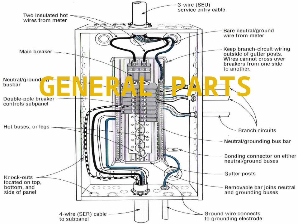
GENERAL PARTS

7
CLASSIFICATIONSwitchboards may be classified according to: 1. SERVICE2. CONTROL3. FRAMEWORK4. PANEL MATERIAL5. ARRANGEMENT

SERVICE
It is practically impossible to cover every type of switchboard application, but few of the most important ones are given in the following.

A. DIRECT CURRENTDirect current panels may be for generator, converter, or general lighting and power service.

10
In all direct current switchboard installations it is important that the [carbon] circuit breakers be mounted at the top of the panel in order that the ARC produced when breaking a heavy current will not damage any other equipment on the board.

11
For installations such as a typical three-wire dc generator, it is necessary to use two circuit breakers and also two ammeters, which are placed in the two outside lines. The equalizer switch may be mounted on the control panel or on a pedestal which is generally placed near the machine.A combination switch having two sets of contacts is sometimes used in the mainline and equalizer circuits.

12
A DC SWITCHBOARD PANEL

13
For large capacity installations it may be advisable to mount the circuit breakers on a separate panel which may be placed near the generator or at some other convenient place in the power plant.

14
Voltmeters are not as a general rule mounted on the switchboard panels, but on swinging brackets on the end panel, the voltage of any particular machine or circuit being read by means of a plugging arrangement.

15
B. ALTERNATING CURRENTIn this presentation, a few of the
outstanding types of AC switchboards that are commonly used in power plants are discussed, no mention being made of special applications.

16
Every application must be studied by itself and the proper type, construction, and arrangement of panels and equipment made accordingly.

17
METHODS OF CONTROL
The control of switchboards may be:
1. DIRECT MANUAL
2. MANUAL REMOTE
3. ELECTRICAL REMOTE

18
DIRECT MANUAL
All switches, circuit breakers, busbars, and other apparatus of control are mounted either upon the back of the switchboard panels or upon the framework directly back of the panels. All the direct-current switching falls under this category. The maximum voltage seldom exceeds 1,500 volts.
When applied to alternating-current installations, it should not be used to stations which capacity exceeds 3,000 kVA for three-phase, and 2,000 kVA for single-phase and confine its application to 2,500 volts or less, or a maximum limit of 6,600 volts. The size of individual circuit breakers and switches for this type of switchboard be limited to 800 amperes or less per pole at 2,500 volts.

19
MANUAL REMOTE
The oil circuit breakers and busbar structures are mounted at some distance from the switchboards, the circuit breakers being operated by hand through connecting rods, chains, bell cranks, etc.
This type should be confined to switchboards with circuit breakers of 2,000-ampere capacity or less and of 50,000 volts or less, indoor service, and to stations whose capacity does not exceed 25,000 kVA, three-phase. In general, remote manual control is not recommended for outdoor stations.
20
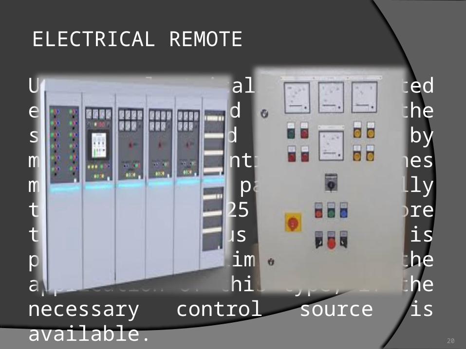
ELECTRICAL REMOTE
Uses electrically operated equipment located apart from the switchboard and operated by means of control switches mounted on the panels. Usually this type cost 25 per cent more than the previous two. There is practically no limitation to the application of this type, if the necessary control source is available.

21
SWITCHBOARD FRAMEWORKThe two standard types or frames for switchboards are made of angle iron and tubular iron.

22
The angle frames are made of standard 3-by 2- by ¼ - in. angle iron, and the tubular types are made up of 1 ¼ - in wrought iron pipe.

23
PANEL MATERIAL
The materials generally used for switchboard panels are SLATE and ASBESTOS EBONY. In recent years ALL-STEEL switchboards have been built for boards that are subjected to very low potentials only.

24
SLATENatural black slate or black marine-finished slate are the two most common materials used for switchboard panels. Natural black slate is more expensive than the black marine-finished slate but has better electrical properties. Slate boards are not desirable for voltages over 600 to 1200 volts.

25
OLD-FASHIONED SWITCHBOARD MADE OF SLATE

26
ASBESTOS EBONY
This material is available in the form of sheets or simple molded forms made up of asbestos fiber thoroughly impregnated with with bonding cements under heat and pressure into a compound of very high dielectric strength. In appearance, it resembles highly surfaced ebony or hard rubber.
27
According to manufacturer’s claims the following are a few of the outstanding merits of asbestos ebony: high dielectric strength good insulation ability to stand shocks and vibration uniform density and light weight unaffected by rapid temperature changes does not shrink, crack, or buckle readily drilled not generally affected by chemicals

28
OLD-FASHIONED SWITCHBOARDS
MADE OF ASBESTOS EBONY

29
STEELWith the absence of live parts, such as
knife switches, on the front of modern electrically operated switchboards, steel panels are especially adaptable to this class of work. Comparing this with slate, some of the outstanding features in favor of steel panels are as follows:
Lower cost in manufacture, shipment, erection, and maintenance.
30
About five times as light in weight. Simplicity in erection, as the steel panel forms its own framework. Easily maintained. Unbreakable. Where an occasional knife switch or other live part must be taken care of, the switch parts are mounted on an insulated base located behind the steel panel and actuated from the front by means of an insulated operating handle.

31
MODERN SWITCHBOARDS MADE OF STEEL

32
ARRANGEMENTThere are a large number of possible
ways in which a switchboard may be arranged, but arrangements are generally made up of one or more of the following:
1.VERTICAL PANELS.
2.CONTROL DESK.
33
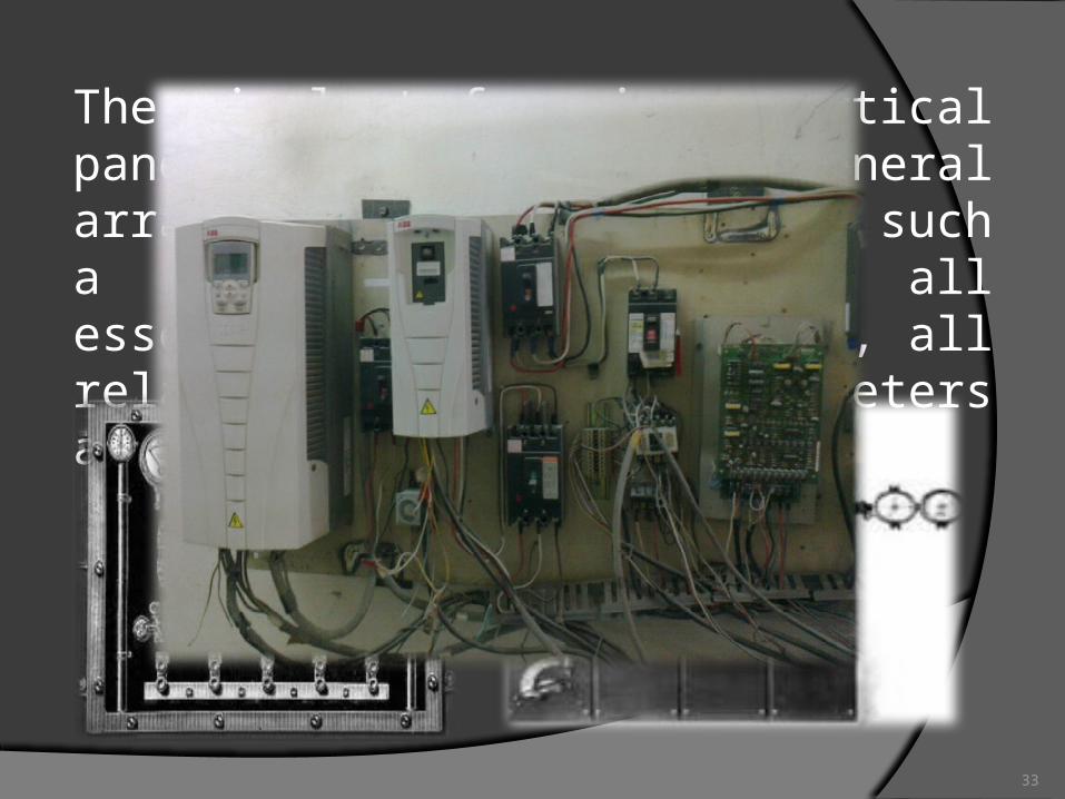
The simplest form is a vertical panel board. The general arrangement of equipment on such a board is to place all essential meters at the top, all relays and nonessential meters at the bottom of the board.

34
A control desk may be used alone when there are a few instruments which can be of the flush type. A slight improvement of this arrangement is obtained by placing the instruments on a small vertical panel at the back of the desk.

35
For medium-sized plants, all control equipment is located on the top of the desk and all essential meters on the vertical panel.

36
Any of the above arrangements may be mounted in a straight line, known as linear switchboard; or in the arc of a circle, known as a SEMICIRCULAR SWITCHBOARD.

37
Its use, however, requires a large space and hence sometimes rejected on that account. For small switchboards it does not offer any advantages over the linear type of switchboard.

38
A special arrangement used for industrial substations and for central-station auxiliary circuits commonly known as the truck-type panel.

39
The busbars are mounted in a steel housing, and the panel, circuit breaker, and instrument transformers are on a removable truck. Truck type panels are equipped with either manually operated or electrically operated circuit breakers. The panels are usually made of steel.
40
The principal advantages of the truck-type panels are as follows:1. All live parts are totally enclosed, and
mechanical interlocks prevent mistakes in operation.
2. All parts requiring inspection are on a removable truck which is “dead” on all sides when removed from the housing.
3. A truck may be replaced by a spare one in a few moments’ time and the circuit breaker inspected without a prolonged interruption of service.
41
The wiring of electrically operated switchboard panels should be done in a neat and orderly manner in order that extensions or repairs may easily be accomplished.
WIRING OF ELECTRICALLY OPERATED SWITCHBOARDS

42
FLAT PANEL WIRING

43
ANGLE-IRON WIRING

44
“L” BRACKET WIRING
45
INSTRUMENTS AND CONTROL EQUIPMENTBelow are listed the general instruments and other equipment that may be found on different types of switchboards.a. Alternating-current Generator Circuits.
One AC ammeter for balanced loads. For unbalanced loads one ammeter with a switching equipment for reading the current in all lines should be used.
One AC voltmeter.
46
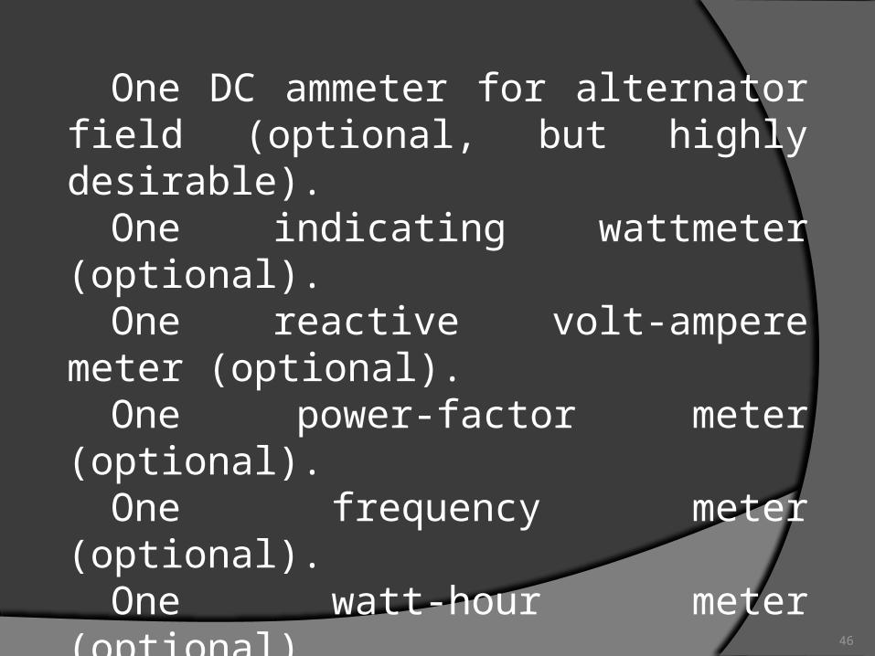
One DC ammeter for alternator field (optional, but highly desirable).
One indicating wattmeter (optional).One reactive volt-ampere meter
(optional).One power-factor meter (optional).One frequency meter (optional).One watt-hour meter (optional).One field switch with discharge
resistance clips.

47
One voltmeter switch for reading all phase voltages, with removable handle or plug.
One mechanism or control switch for controlling the generator field rheostat. If a separate exciter panel is not used, a mechanism or control switch for the control of the exciter-field rheostat is also essential.
One synchronizing outfit (not required for a single generator).
One control device for prime-mover governor (optional).
48
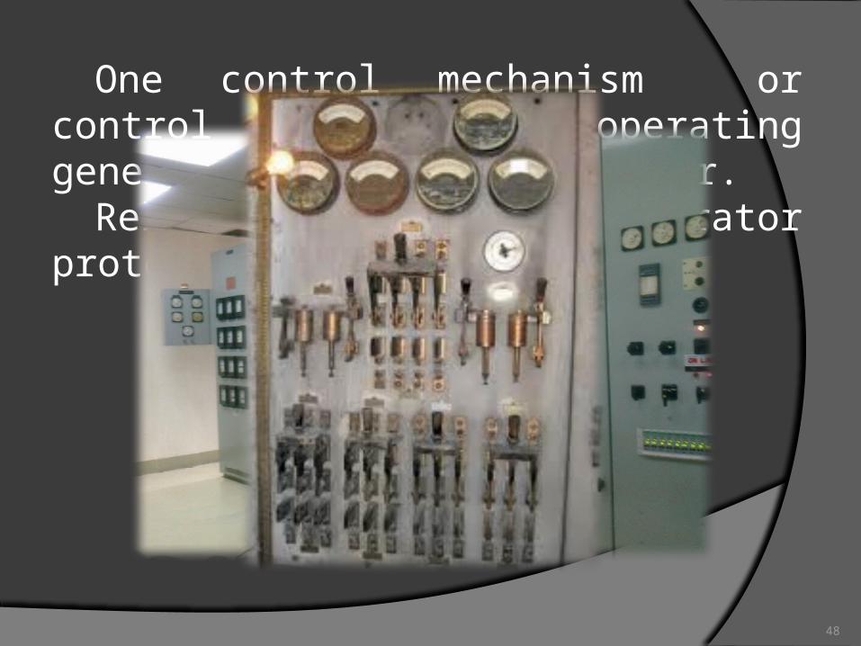
One control mechanism or control switch for operating generator oil circuit breaker.
Relays for generator protection (optional).

49
b. Feeder Circuits for Motor or Power Service.
One alternating current ammeter for balanced loads, or one ammeter with ammeter switch, or one ammeter per phase.
One reactive volt-ampere meter.One power-factor meter.One watt-hour meter.One circuit breaker control, either
mechanical or electrical.Relay equipment.

50
51
c. Transmission Lines to Substations or Tie Lines to Other Power Plants.
Three ammeters or one ammeter with polyphase switching device.
One indicating wattmeter.One reactive volt-ampere meter.One power factor meter (optional).One voltmeter or voltmeter receptacle
(optional).

52
One watt-hour meter (optional).One synchronizing outfit (required for
tie line only).One control for oil circuit breaker.Relays (optional).

53
d. Synchronous Motor Panel.One AC ammeter.One DC field ammeter.One power factor meter (optional).One indicating wattmeter (optional).One field rheostat control.One field discharge switch or switch
control.One synchronizing outfit (not
required if motor is self-starting).One control for oil circuit breaker.Relays.
54

55
e. Synchronous Condenser Panel.
One AC ammeter.One DC field ammeter.One wattless indicating volt-ampere
meter.One field rheostat control.One field-discharge switch or switch
control.One control for oil- circuit breaker.Relay equipment.

56

57
MINIATURE BUSFor the proper and efficient operation
of electrically operated switchboards, a miniature bus is desirable.
The miniature bus is a skeleton or single-line diagram of all main circuits of the station, with devices for indicating the relative location of all circuit breakers, disconnecting switches, generators, power transformers, and feeder circuits.
JOKE ONLY!!!

58
The miniature bus is generally made of polished copper strap run along the top of the control desk or, in the case of a vertical board, on the face of the panel. For stations having circuits at different voltage it is highly desirable to indicate the different voltages by means of different finishes given to the miniature bus. Red and green lamps are generally placed in the miniature bus to indicate the position of switches, circuit breakers, or other equipment.

59
Red light generally indicates that the switch or oil circuit breaker is closed, and the green light, the open position.

60
Thanks for watching!!!
ANO? EXAM NA?!!3
21..

61
QUESTIONS:1.) It is a type of switchboard control that
uses electrically operated equipment located apart from the switchboard and operated by means of control switches mounted on the panels.
2-3.) Give at least two (2) classification of switchboards.
4.) It is a large single panel, frame, or assembly of panels on which are mounted, on the face, back, or both, switches, overcurrent and other protective devices, buses, and usually instruments.
62
5.) In all direct current switchboard installations it is important that the [carbon] circuit breakers be mounted at the top of the panel in order that the _______ produced when breaking a heavy current will not damage any other equipment on the board.
6.) This switchboard material is not desirable for voltages over 600 to 1200 volts.7.) It is a switchboard arrangement that has its components mounted in a shape similar to an arc of a circle.

63
8.) One advantage of this type of panel is that all live parts are totally enclosed, and mechanical interlocks prevent mistakes in operation. What is this type of switchboard panel?
9-10.) In miniature buses, what does a red and green light indicate about the switch or oil circuit breaker?
GOOD LUCK!!!