switch port security - 202.62.95.70:8080
TRANSCRIPT
Switch Port Security

Example

Access and Trunk Ports
Switch Port Security
• Remembers The Ethernet MAC address connected to the switch port
• Allows only that MAC address to communicate on that port
• If any other MAC address tries to communicate through the port, port security will disable the port.

Violation
• Violation tells the switch what to do when the number of MAC addresses on the port has exceeded the maximum.
• Protect
• Restrict
• Shutdown

• Protect – data from unknown source MAC addresses are dropped; a security notification IS NOT presented by the switch
• Restrict - data from unknown source MAC addresses are dropped and the violation counter increments.
• Shutdown – (default mode) interface becomes error-disabled and port LED turns off. The violation counter increments. Issues the shutdown and then the no shutdown command on the interface to bring
it out of the error-disabled state.
Switch Port Security
Port Security: Violation Modes

• Before configuring port-security features, place the port in access mode and use the switchport port-security interface configuration command to enable port security on an interface.
Switch Port Security
Port Security: Configuring (Cont.)

Switch Port Security
Port Security: Configuring (Cont.)

Commands for Switch port security

2© 2016 Cisco and/or its affiliates. All rights reserved. Cisco Confidential
4.1 Link Aggregation Concepts

3© 2016 Cisco and/or its affiliates. All rights reserved. Cisco Confidential
It is possible to combine the number of physical links between switches to increase the overall
speed of switch-to-switch communication.
• Etherchannel was originallly developed by Cisco
as a LAN switch-switch technique of grouping gigabit or
fast ethernet ports into one logical port.
• When an etherchannel is formed, the resulting
virtual interface is called a port channel.
STP will block redundant links to prevent routing loops.
Link Aggregation
Introduction to Link Aggregation
Redundant Links with STP (by default blocked)
4© 2016 Cisco and/or its affiliates. All rights reserved. Cisco Confidential
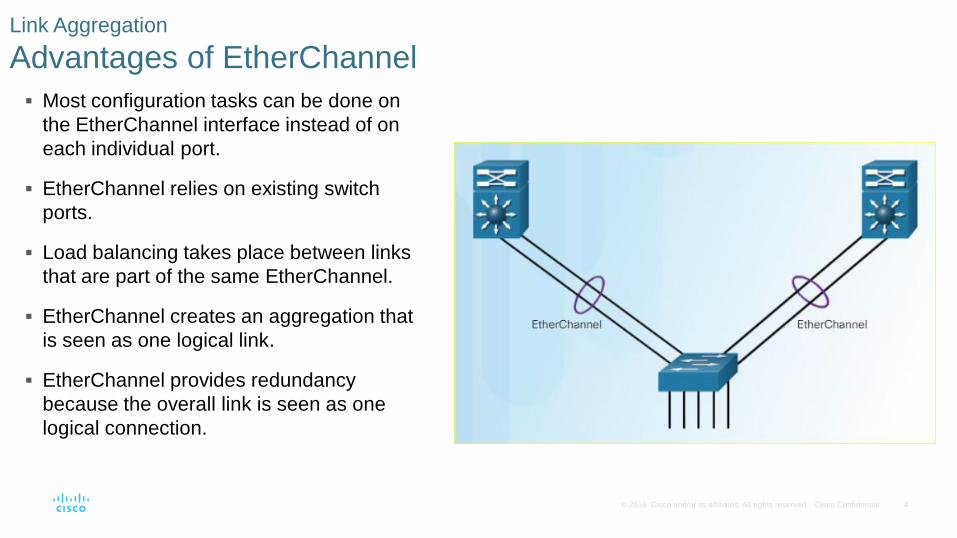
Link Aggregation
Advantages of EtherChannel
Most configuration tasks can be done on
the EtherChannel interface instead of on
each individual port.
EtherChannel relies on existing switch
ports.
Load balancing takes place between links
that are part of the same EtherChannel.
EtherChannel creates an aggregation that
is seen as one logical link.
EtherChannel provides redundancy
because the overall link is seen as one
logical connection.

5© 2016 Cisco and/or its affiliates. All rights reserved. Cisco Confidential
EtherChannel groups multiple physical ports into one or more logical EtherChannel links.
EtherChannel Operation
Implementation Restrictions
EtherChannel Restrictions
• Interface types cannot be mixed. (Fast
Ethernet + Gigabit Ethernet cannot be grouped.)
• Provides full-duplex bandwidth up to 800 Mbps
(Fast EtherChannel) or 8 Gbps (Gigabit
EtherChannel)
• Cisco IOS Switch can support 6 EtherChannels.
• Created between two switches or a server and
switch.
• If one side is configured as trunk, the other side
must be a trunk within same native VLAN.
• Each EtherChannel has a logical port channel
interface and changes to a channel affects its
physical interfaces.
6© 2016 Cisco and/or its affiliates. All rights reserved. Cisco Confidential
EtherChannels can be formed through negotiation using one of two protocols, Port Aggregation
Protocol (PAgP) or Link Aggregation Control Protocol (LACP).
These protocols allow ports with similar characteristics to form a channel through dynamic
negotiation with adjoining switches.
Note: It is also possible to configure a static or unconditional EtherChannel without PAgP or LACP.
AutoNegotiation Protocols

7© 2016 Cisco and/or its affiliates. All rights reserved. Cisco Confidential
PAgP (pronounced “Pag - P”) is a Cisco-proprietary protocol that aids in the automatic creation of
EtherChannel links.
When an EtherChannel link is configured using PAgP, PAgP packets are sent between
EtherChannel-capable ports to negotiate the forming of a channel.
When PAgP identifies matched Ethernet links, it groups the links into an EtherChannel. The
EtherChannel is then added to the spanning tree as a single port.
When enabled, PAgP also manages the EtherChannel. PAgP packets are sent every 30 seconds.
PAgP checks for configuration consistency and manages link additions and failures between two
switches. It ensures that when an EtherChannel is created, all ports have the same type of
configuration.
PaGP

8© 2016 Cisco and/or its affiliates. All rights reserved. Cisco Confidential
The modes for PAgP as follows:
On - This mode forces the interface to channel without PAgP. Interfaces configured in the on mode
do not exchange PAgP packets.
PAgP desirable - This PAgP mode places an interface in an active negotiating state in which the
interface initiates negotiations with other interfaces by sending PAgP packets.
PAgP auto - This PAgP mode places an interface in a passive negotiating state in which the
interface responds to the PAgP packets that it receives but does not initiate PAgP negotiation.
.
PaGP
9© 2016 Cisco and/or its affiliates. All rights reserved. Cisco Confidential
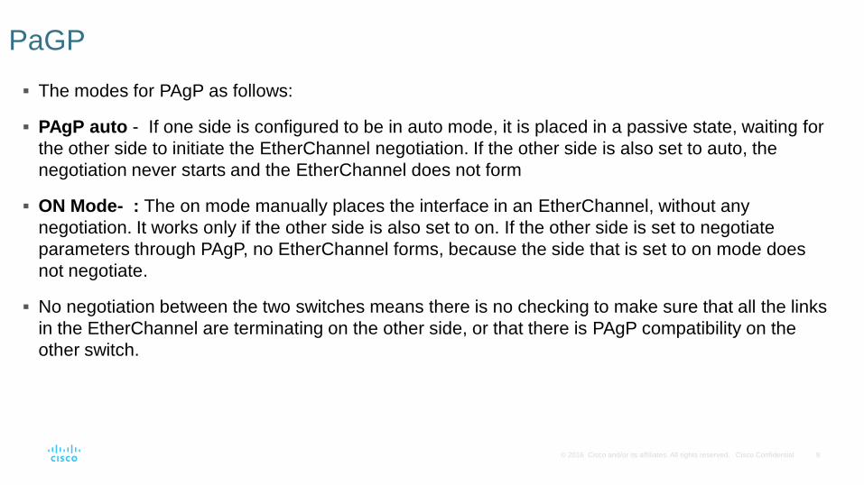
The modes for PAgP as follows:
PAgP auto - If one side is configured to be in auto mode, it is placed in a passive state, waiting for
the other side to initiate the EtherChannel negotiation. If the other side is also set to auto, the
negotiation never starts and the EtherChannel does not form
ON Mode- : The on mode manually places the interface in an EtherChannel, without any
negotiation. It works only if the other side is also set to on. If the other side is set to negotiate
parameters through PAgP, no EtherChannel forms, because the side that is set to on mode does
not negotiate.
No negotiation between the two switches means there is no checking to make sure that all the links
in the EtherChannel are terminating on the other side, or that there is PAgP compatibility on the
other switch.
PaGP

10© 2016 Cisco and/or its affiliates. All rights reserved. Cisco Confidential
EtherChannels can be formed by using PAgP or LACP protocol
PAgP (“Pag-P”) Cisco-proprietary protocol
EtherChannel Operation
Port Aggregation Protocol

11© 2016 Cisco and/or its affiliates. All rights reserved. Cisco Confidential
LACP is part of an IEEE specification (802.3ad) that allows several physical ports to be bundled to
form a single logical channel.
LACP allows a switch to negotiate an automatic bundle by sending LACP packets to the other
switch.
Because LACP is an IEEE standard, it can be used to facilitate EtherChannels in multivendor
environments. On Cisco devices, both protocols are supported.
LACP
12© 2016 Cisco and/or its affiliates. All rights reserved. Cisco Confidential
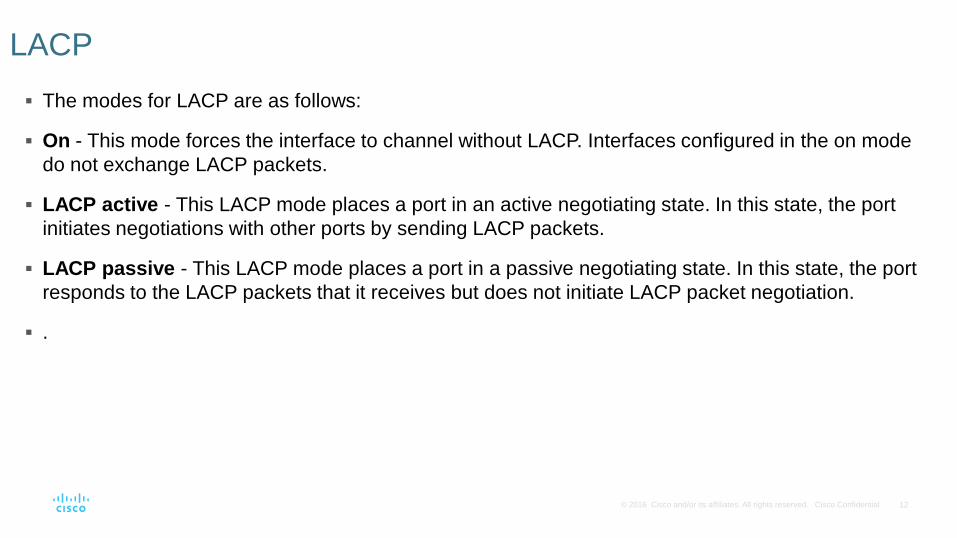
The modes for LACP are as follows:
On - This mode forces the interface to channel without LACP. Interfaces configured in the on mode
do not exchange LACP packets.
LACP active - This LACP mode places a port in an active negotiating state. In this state, the port
initiates negotiations with other ports by sending LACP packets.
LACP passive - This LACP mode places a port in a passive negotiating state. In this state, the port
responds to the LACP packets that it receives but does not initiate LACP packet negotiation.
.
LACP

13© 2016 Cisco and/or its affiliates. All rights reserved. Cisco Confidential
LACP multivendor environment
EtherChannel Operation
Link Aggregation Control Protocol
14© 2016 Cisco and/or its affiliates. All rights reserved. Cisco Confidential
4.2 Link Aggregation Configuration

15© 2016 Cisco and/or its affiliates. All rights reserved. Cisco Confidential
Configuration Settings Match on Both Switches
• Same speed and duplex mode.
• All interfaces in a bundle must be assigned to the same VLAN, or configured as a trunk.
• Trunk must support same range of VLANs.
Configuring EtherChannel
Configuration Guidelines

16© 2016 Cisco and/or its affiliates. All rights reserved. Cisco Confidential
Configuration Modes
Configuring EtherChannel
Configuration Guidelines
17© 2016 Cisco and/or its affiliates. All rights reserved. Cisco Confidential
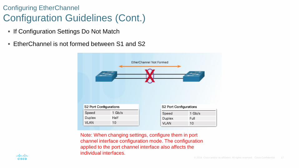
If Configuration Settings Do Not Match
EtherChannel is not formed between S1 and S2
Configuring EtherChannel
Configuration Guidelines (Cont.)
Note: When changing settings, configure them in port
channel interface configuration mode. The configuration
applied to the port channel interface also affects the
individual interfaces.

18© 2016 Cisco and/or its affiliates. All rights reserved. Cisco Confidential
This configuration creates EtherChannel with LACP and configures trunking.
• Step 1: Specify the interfaces that compose the EtherChannel group.
• Step 2: Create the port channel interface with the channel-group command in active mode. (Channel
group number needs to be selected.)
• Step 3: Change Layer 2 settings in port channel interface configuration mode.
Configuring EtherChannel
Configuring Interfaces

19© 2016 Cisco and/or its affiliates. All rights reserved. Cisco Confidential
Configuring EtherChannel
Packet Tracer – Configuring EtherChannel

20© 2016 Cisco and/or its affiliates. All rights reserved. Cisco Confidential
Verifying and Troubleshooting EtherChannel
Verifying EtherChannel
Verifies the interface status.
Displays a one-line summary
per channel group.
SU indicates in use.

21© 2016 Cisco and/or its affiliates. All rights reserved. Cisco Confidential
Verifying and Troubleshooting EtherChannel
Verifying EtherChannel (Cont.)
Displays port channel
information.

22© 2016 Cisco and/or its affiliates. All rights reserved. Cisco Confidential
Verifying and Troubleshooting EtherChannel
Verifying EtherChannel (Cont.)
Displays role of particular
interface in an EtherChannel.
23© 2016 Cisco and/or its affiliates. All rights reserved. Cisco Confidential
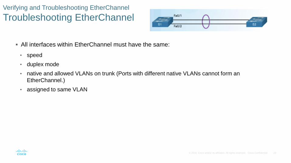
Verifying and Troubleshooting EtherChannel
Troubleshooting EtherChannel
All interfaces within EtherChannel must have the same:
• speed
• duplex mode
• native and allowed VLANs on trunk (Ports with different native VLANs cannot form an
EtherChannel.)
• assigned to same VLAN
24© 2016 Cisco and/or its affiliates. All rights reserved. Cisco Confidential
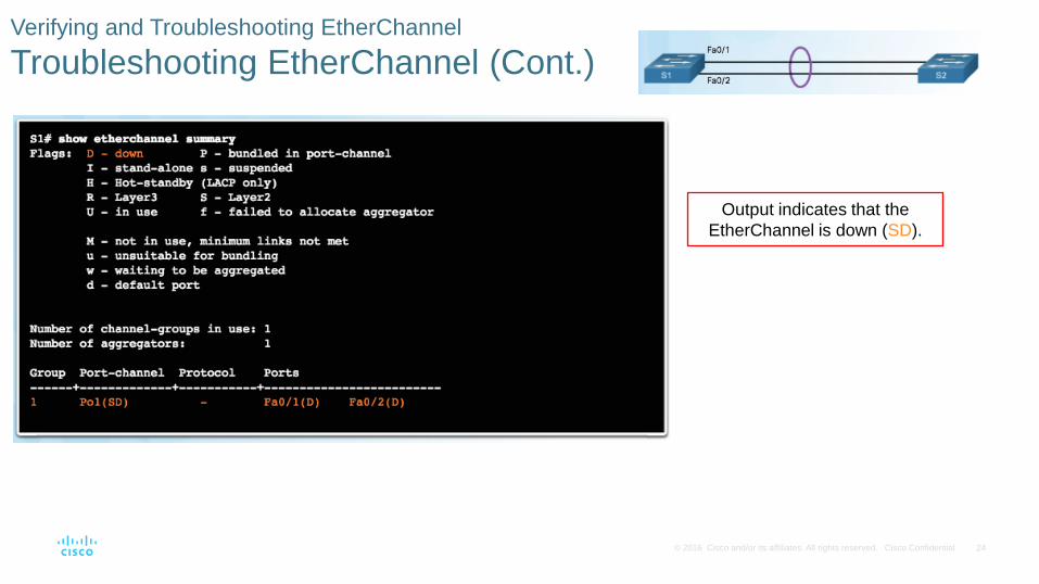
Verifying and Troubleshooting EtherChannel
Troubleshooting EtherChannel (Cont.)
Output indicates that the
EtherChannel is down (SD).

25© 2016 Cisco and/or its affiliates. All rights reserved. Cisco Confidential
Verifying and Troubleshooting EtherChannel
Troubleshooting EtherChannel (Cont.)
Incompatible PAgP modes
configured on S1 and S2.

26© 2016 Cisco and/or its affiliates. All rights reserved. Cisco Confidential
Verifying and Troubleshooting EtherChannel
Troubleshooting EtherChannel (Cont.)
PAgP mode on the EtherChannel
is changed to desirable and the
EtherChannel becomes active.

MATCH THE FOLLOWING :
1 a) Multicast Transmission
2. b) Unicast Transmission
3.
c) Broadcast Transmission

LANs – Scenario-1

LANs – Scenario-2

LANs – Scenario-3

WHAT?
WHY?
HOW?
VIRTUAL LANs

WHAT ARE VLANS ?

• VLANs can segment LAN devices without regard for the physical location of the user or device.
– In the figure, IT users on the first, second, and third floors are all on the same LAN segment. The same is true for HR and Sales users.
• A VLAN is a logical partition of a Layer 2 network.
– Multiple partitions can be created and multiple VLANs can co-exist.
– The partitioning of the Layer 2 network takes place inside a Layer 2 device, usually via a switch.
– Each VLAN is a broadcast domain that can span multiple physical LAN segments.
– Hosts on the same VLAN are unaware of the VLAN’s existence.
Overview of VLANs
VLAN Definitions
VLANs are mutually isolated and packets can only pass between VLANs via a router.

Overview of VLANs
Benefits of VLANs

• Common types of VLANs:– Default VLAN – Also known as VLAN 1.
All switch ports are members of VLAN 1 by default.
– Data VLAN – Data VLANs are commonly created for specific groups of users or devices. They carry user generated traffic.
– Native VLAN – This is the VLAN that carries all untagged traffic (CONTROL TRAFFIC). This is traffic that does not originate from a VLAN port (e.g., STP BPDU traffic exchanged between STP enabled switches). The native VLAN is VLAN 1 by default.
– Management VLAN – This is a VLAN that is created to carry network management traffic including SSH, SNMP, Syslog, and more. VLAN 1 is the default VLAN used for network management.
Overview of VLANs
Types of VLANsDefault VLAN Assignment
Initially, all switch ports are members of VLAN 1.

• A VLAN trunk is a point-to-point link that carries more than one VLAN.– Usually established
between switches to support intra VLAN communication.
– A VLAN trunk or trunk ports are not associated to any VLANs.
• Cisco IOS supports IEEE 802.1q, a popular VLAN trunk protocol.
VLANs in a Multi-Switched Environment
VLAN Trunks
The links between switches S1 and S2, and S1 and S3 are configured to transmit traffic coming from VLANs 10, 20, 30, and 99 across the network.

• If a switch port receives a broadcast frame, it forwards it out all ports except the originating port. – Eventually the entire network receives the broadcast because the network is one
broadcast domain.
• VLANs can be used to limit the reach of broadcast frames because each VLAN is a broadcast domain.– VLANs help control the reach of broadcast frames and their impact in the network.
VLANs in a Multi-Switched Environment
Controlling Broadcast Domains with VLANs
In the figure, PC1 on VLAN 10 sends a broadcast frame.
• Trunk links between S2 - S1 and S1 - S3 propagate the broadcast to other devices in VLAN 10.
• Only devices in the same VLAN receive the broadcast therefore, PC4 would receive the broadcast.

• Before a frame is forwarded across a trunk link, it must be tagged with its VLAN information.
– Frame tagging is the process of adding a VLAN identification header to the frame.
– It is used to properly transmit multiple VLAN frames through a trunk link.
• IEEE 802.1Q is a vey popular VLAN trunking protocol that defines the structure of the tagging header added to the frame.
VLANs in a Multi-Switched Environment
Tagging Ethernet Frames for VLAN Identification
• Switches add VLAN tagging information after the Source MAC address field.
• The fields in the 802.1Q VLAN tag includes VLAN ID (VID).
• Trunk links add the tag information before sending the frame and then remove the tags before forwarding frames through non-trunk ports.

• Control traffic sent on the native VLAN should not be tagged.
• Frames received untagged, remain untagged and are placed in the native VLAN when forwarded.
• If there are no ports associated to the native VLAN and no other trunk links, an untagged frame is dropped.
• When configuring a switch port on a Cisco switch, configure devices so that they do not send tagged frames on the native VLAN.
• In Cisco switches, the native VLAN is VLAN 1, by default.
• https://www.youtube.com/watch?v=Fmq1E1Qr2W4 //native vlan
• https://www.youtube.com/watch?v=dpoUjnfGbeo
VLANs in a Multi-Switched Environment
Native VLANs and 802.1Q Tagging

14© 2016 Cisco and/or its affiliates. All rights reserved. Cisco Confidential
6.2 VLAN Implementation
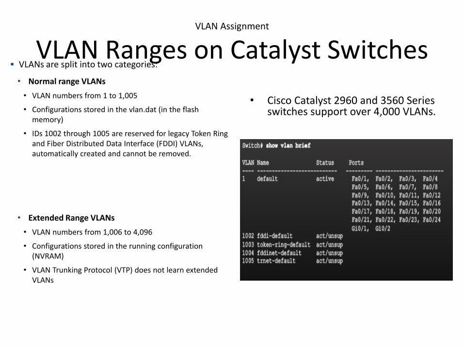
• Cisco Catalyst 2960 and 3560 Series switches support over 4,000 VLANs.
VLAN Assignment
VLAN Ranges on Catalyst Switches VLANs are split into two categories:
• Normal range VLANs
• VLAN numbers from 1 to 1,005
• Configurations stored in the vlan.dat (in the flash memory)
• IDs 1002 through 1005 are reserved for legacy Token Ring and Fiber Distributed Data Interface (FDDI) VLANs, automatically created and cannot be removed.
• Extended Range VLANs
• VLAN numbers from 1,006 to 4,096
• Configurations stored in the running configuration (NVRAM)
• VLAN Trunking Protocol (VTP) does not learn extended VLANs
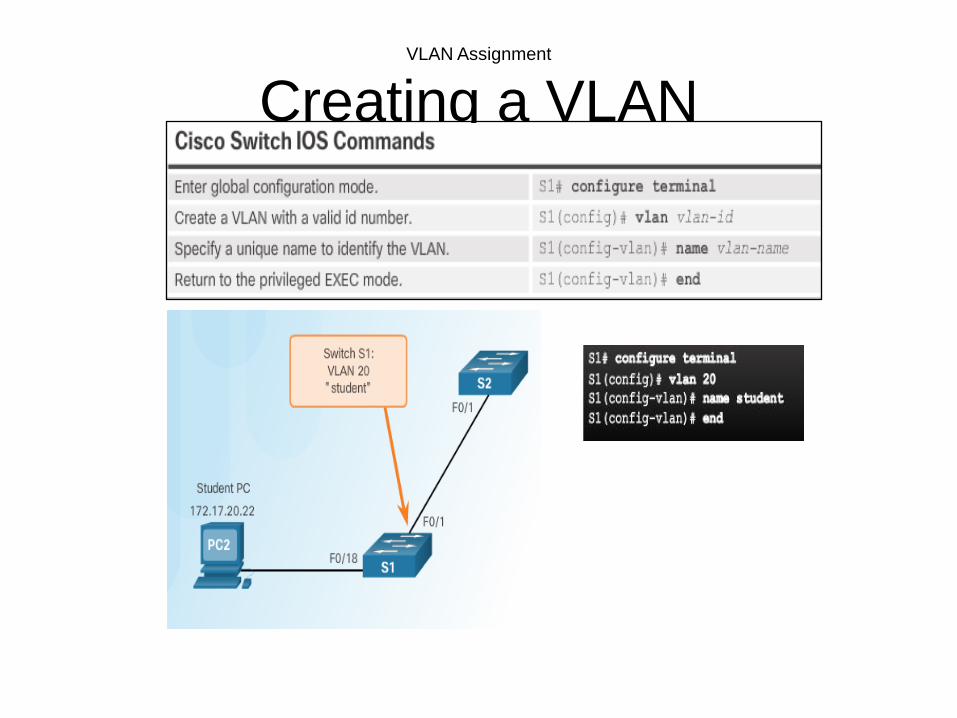
VLAN Assignment
Creating a VLAN

VLAN Assignment
Assigning Ports to VLANs
Example 1 Example 2

• Remove VLAN Assignment
VLAN Assignment
Changing VLAN Port Membership
Even though interface F0/18 was previously assigned to VLAN 20, it reset to the default VLAN1.

• Use the no vlan vlan-id global configuration mode command to remove VLAN.
• To delete the entire vlan.dat file, use the delete flash:vlan.dat privileged EXEC mode command.
– delete vlan.dat can be used if the vlan.dat file has not been moved from its default location.
VLAN Assignment
Deleting VLANs

• VLAN configurations can be validated using the Cisco IOS show vlan and show interfaces command options.
VLAN Assignment
Verifying VLAN Information

VLAN Trunks
Configuring IEEE 802.1q Trunk Links
Native VLANVLAN 99
172.17.99.0/24

22© 2016 Cisco and/or its affiliates. All rights reserved. Cisco Confidential
6.3 Inter-VLAN Routing Using Routers

Inter-VLAN Routing Operation
What is Inter-VLAN Routing?
• Layer 2 switches cannot forward traffic between VLANs without the assistance of a router.
• Inter-VLAN routing is a process for forwarding network traffic from one VLAN to another, using a router.
• There are three options for inter-VLAN routing:
– Legacy inter-VLAN routing
– Router-on-a-Stick
– Layer 3 switching using SVIs //not in course

• In the past:– Router interfaces were used to
route between VLANs.– Each VLAN was connected to a
different physical router interface.
– Packets would arrive on the router through one interface, be routed and leave through another.
– Because the router interfaces were connected to VLANs and had IP addresses from that specific VLAN, routing between VLANs was achieved.
– Large networks with large number of VLANs required many router interfaces.
Inter-VLAN Routing Operation
Legacy Inter-VLAN RoutingIn this example, the router was configured with two separate physical interfaces to interact with the different VLANs and perform the routing.

• The router-on-a-stick approach uses only one of the router’s physical interface.– One of the router’s physical
interfaces is configured as a 802.1Q trunk port so it can understand VLAN tags.
– Logical subinterfaces are created; one subinterface per VLAN.
– Each subinterface is configured with an IP address from the VLAN it represents.
– VLAN members (hosts) are configured to use the subinterface address as a default gateway.
Inter-VLAN Routing Operation
Router-on-a-Stick Inter-VLAN RoutingIn this example, the R1 interface is configured as a trunk link and connects to the trunk F0/4 port on S1. • Router accepts VLAN-tagged traffic on the trunk interface• Router internally routes between the VLANs using subinterfaces. • Router then forwards the routed traffic as VLAN-tagged for the
destination VLAN out the trunk link.

• Legacy inter-VLAN routing requires routers to have multiple physical interfaces.
• Each one of the router’s physical interfaces is connected to a unique VLAN.
• Each interface is also configured with an IP address for the subnet associated with the particular VLAN.
• Network devices use the router as a gateway to access the devices connected to the other VLANs.
Configure Legacy Inter-VLAN Routing
Configure Legacy Inter-VLAN Routing: Preparation

• Configure the VLANs on the switch and then assign the ports to their respective VLANs.
• In this example, the S1 ports are configured as follows:– Ports F0/4 and F0/11 of S1 are on VLAN
10 – Ports F0/5 and F0/16 ports are on VLAN
30.
Configure Legacy Inter-VLAN Routing
Configure Legacy Inter-VLAN Routing: Switch Configuration

Configure Legacy Inter-VLAN Routing
Configure Legacy Inter-VLAN Routing: Router Interface Configuration
• Next configure the router interfaces.

• An alternative to legacy inter-VLAN routing is to use VLAN trunking and subinterfaces.
• VLAN trunking allows a single physical router interface to route traffic for multiple VLANs.
• The physical interface of the router must be connected to a trunk link on the adjacent switch.
• On the router, subinterfaces are created for each unique VLAN.
• Each subinterface is assigned an IP address specific to its subnet or VLAN and is also configured to tag frames for that VLAN.
Configure Router-on-a-Stick Inter-VLAN Routing
Configure Router-on-a Stick: Preparation
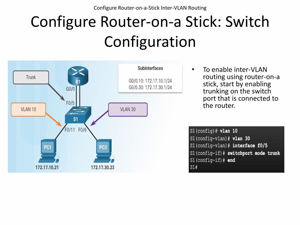
• To enable inter-VLAN routing using router-on-a stick, start by enabling trunking on the switch port that is connected to the router.
Configure Router-on-a-Stick Inter-VLAN Routing
Configure Router-on-a Stick: Switch Configuration

• The router-on-a-stick method requires subinterfaces to be configured for each routable VLAN.– The subinterfaces must be
configured to support VLANs using the encapsulation dot1Q VLAN-ID interface configuration command.
Configure Router-on-a-Stick Inter-VLAN Routing
Configure Router-on-a Stick: Router Subinterface Configuration

• By default, Cisco routers are configured to route traffic between local subinterfaces.
– As a result, routing does not specifically need to be enabled.
• Use the show vlan and show ip route commands to verify the subinterface configurations.
Configure Router-on-a-Stick Inter-VLAN Routing
Configure Router-on-a Stick: Verifying Subinterfaces
The show vlan command displays information about the Cisco IOS VLAN subinterfaces.
The show ip route command displays the routing table containing the networks associated with outgoing subinterfaces.
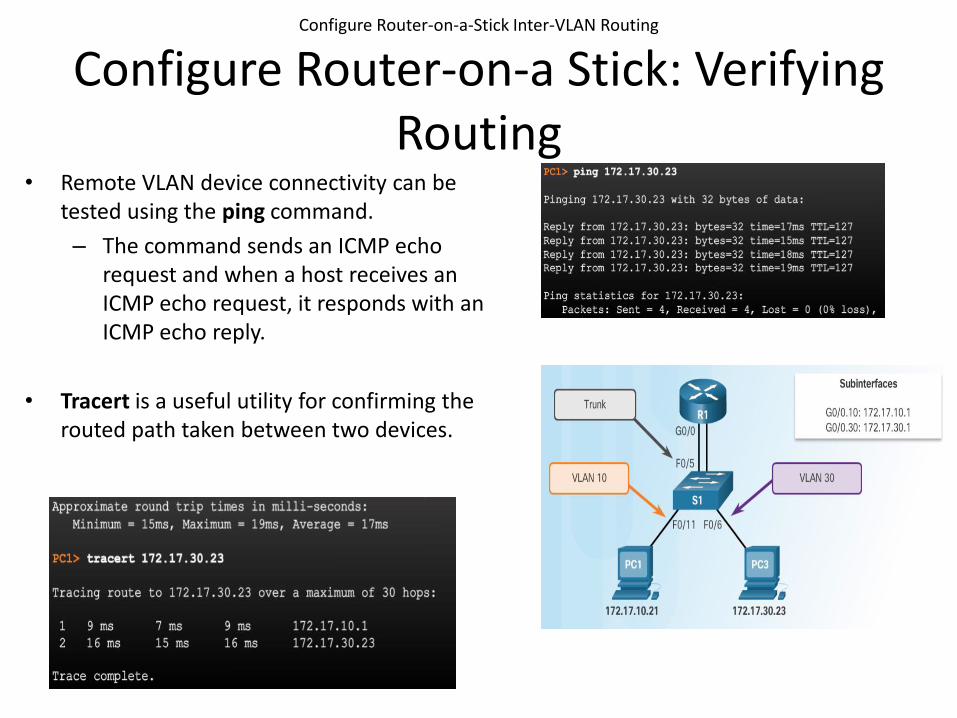
• Remote VLAN device connectivity can be tested using the ping command.
– The command sends an ICMP echo request and when a host receives an ICMP echo request, it responds with an ICMP echo reply.
• Tracert is a useful utility for confirming the routed path taken between two devices.
Configure Router-on-a-Stick Inter-VLAN Routing
Configure Router-on-a Stick: Verifying Routing

Spanning-Tree Protocol

2© 2016 Cisco and/or its affiliates. All rights reserved. Cisco Confidential
3.1 STP Operation

Spanning Tree
LEARNING MECHANISM IN BRIDGES/SWITCHES
MAC ADDRESS Port/Interface
PC4 F0/2
PC6 F0/1
MAC ADDRESS TABLE- S-3
PC4-PC6

• Switched networks commonly have redundant paths and even redundant links between the same two devices.
– Redundant paths eliminate a single point of failure in order to improve reliability and availability.
– Redundant paths can cause physical and logical Layer 2 loops.
• Spanning Tree Protocol (STP) is a Layer 2 protocol that helps especially when there are redundant links.
• Layer 2 loop issues– Mac database instability –
copies of the same frame being received on different ports.
– Broadcast storms – broadcasts are flooded endlessly causing network disruption.
– Multiple frame transmission –multiple copies of unicast frames delivered to the same destination.
Spanning Tree
Redundancy at OSI Layers 1 and 2

• Ethernet frames do not have a time to live (TTL) field like the Layer 3 IP header has. This means that Ethernet has no mechanism to drop frames that propagate endlessly. This can
result in MAC database instability.1. PC1 sends a broadcast frame to S2.2. S2 updates the MAC address table for PC1’s MAC address on port 11.3. S2 forwards the frame out all ports except the port the frame came
in on. S1 and S3 receive the frame on a trunk and update their own MAC address tables that PC1 is reachable through the trunk port.
4. S1 and S3 send the frame out all ports except the port it came in on.5. When S1 sends the frame out port 2 (Trunk 3), S3 updates the MAC
address table to reflect that PC1 is now reachable through port 1.
– A host caught in a network loop is not accessible to other hosts.
– Due to constant changes in the MAC address table, Switches S3 and S1 do not know which port to forward frames.
Spanning Tree
Issues with Layer 1 Redundancy: MAC Database Instability

Spanning Tree
Issues with Layer 1 Redundancy: MAC Database Instability

• Broadcast storm – so many broadcast frames in a Layer 2 loop that use all available bandwidth and make the network unreachable for legitimate network traffic. – Causes a denial of service (DoS)– Can develop in seconds and bring the network down
Spanning Tree
Issues with Layer 1 Redundancy: Broadcast Storms

• An unknown unicast frame is when the switch does not have the destination MAC address in its MAC address table and has to broadcast the frame out all ports except the port the frame was received on (the ingress port).
• Unknown unicast frames sent onto a looped network can result in duplicate frames arriving at the destination device.
1. PC1 sends a frame destined for PC4.2. S2 does not have PC4’s MAC address in
the MAC address table so it forwards the frame out all ports including the trunks that lead to S1 and S3. S1 sends the frame to PC4. S3 also sends a copy of the frame over to S1 which delivers the same frame again to PC4.
Spanning Tree
Issues with Layer 1 Redundancy: Duplicate Unicast Frames

• The Spanning Tree Protocol (STP) creates one logical path through the switch network (all destinations on the network).– Blocks redundant paths that
could cause a loop.– STP sends bridge protocol data
units (BPDUs) between Layer 2 devices in order to create the one logical path.
• A port on S2 is blocked so traffic can only flow one way between any two devices.
• When Trunk1 fails, the blocked port on S2 is unblocked and traffic can flow between S2 and S3.
STP Operation
Spanning Tree Algorithm: Introduction

• Root bridge – one Layer 2 device in a switched network.
• Root port – one port on a switch that has the lowest cost to reach the root bridge.
• Designated port – selected on a per-segment (each link) basis, based on the cost to get back to root bridge for either side of the link.
• Alternate port – (RSTP only) backup port for the designated port when the other side is not a root port.
• Backup port – (RSTP only) backup port for the root port.
STP Operation
Spanning Tree Algorithm: Port Roles

• Lowest bridge ID (BID) becomes root bridge– Originally BID had two fields:
bridge priority and MAC address– Bridge priority is a value
between 0 and 65,535. The default is 32,768 (can change).Priority on switches can be set in increments of 4096 (i.e it can be 4096, 8192, so on…)
– If priority is same on all switches (i.e if default bridge
– priority is not changed) then lowest MAC address
– becomes root bridge.
STP Operation
Spanning Tree Algorithm: Root BridgeSupports per-VLAN
STP operations
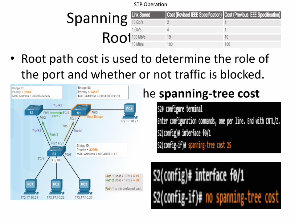
• Root path cost is used to determine the role of the port and whether or not traffic is blocked.
• Can be modified with the spanning-tree cost interface command.
STP Operation
Spanning Tree Algorithm: Root Path Cost

1. When a switch is powered on, it assumes it is the root bridge until BPDUs are sent and STP calculations are performed. S2 sends out BPDUs.
2. S3 compares its root ID with the BPDU from S2. S2 is lower so S3 updates its root ID.
STP Operation
802.1D BPDU Propagation and Process
1.
2

3. S1 receives the same information from S2 and because S1 has a lower BID, it ignores the information from S2.
4. S3 sends BPDUs out all ports indicating that S2 is root bridge.
STP Operation
802.1D BPDU Propagation and Process (Cont.)
3
4

5. S2 compares the info from S3 so S2 still thinks it is root bridge.
6. S1 gets the same information from S3 (that S2 is root bridge), but because S1 has a lower BID, the switch ignores the information in the BPDU.
STP Operation
802.1D BPDU Propagation and Process (Cont.)
5
6

7. S1 now sends out BPDUs out all ports. The BPDU contains information designated S1 as root bridge.
STP Operation
802.1D BPDU Propagation and Process (Cont.)
7.
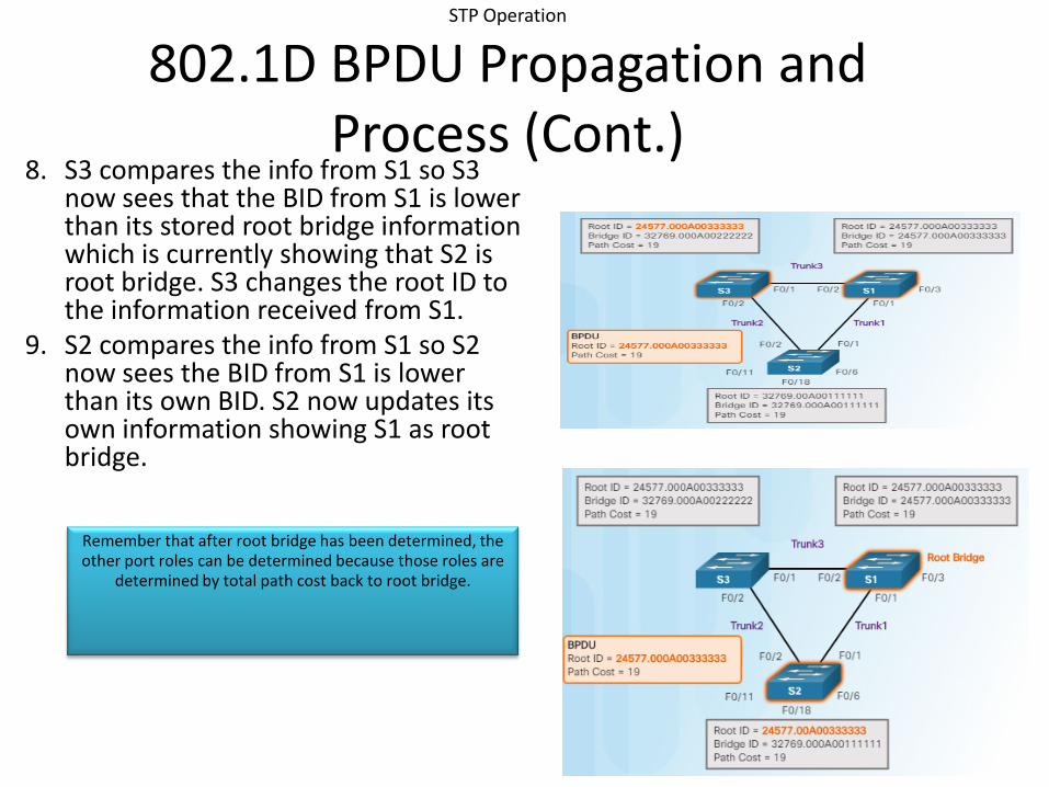
8. S3 compares the info from S1 so S3 now sees that the BID from S1 is lower than its stored root bridge information which is currently showing that S2 is root bridge. S3 changes the root ID to the information received from S1.
9. S2 compares the info from S1 so S2 now sees the BID from S1 is lower than its own BID. S2 now updates its own information showing S1 as root bridge.
STP Operation
802.1D BPDU Propagation and Process (Cont.)
Remember that after root bridge has been determined, the other port roles can be determined because those roles are
determined by total path cost back to root bridge.
STP Operation
Port Role Decisions for RSTP (Cont.)

STP Operation
PATH COST

• S1 is rootbridge
STP Operation
Port Role Decisions for RSTP
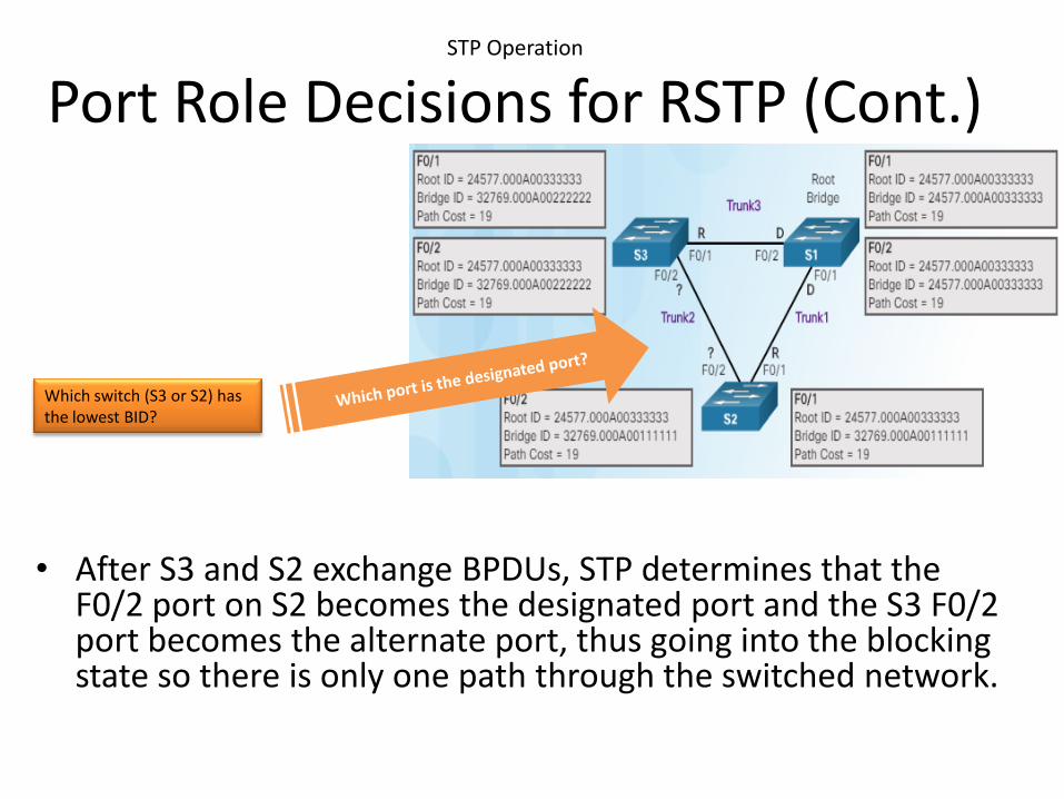
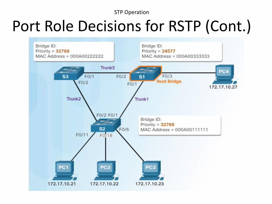
• After S3 and S2 exchange BPDUs, STP determines that the F0/2 port on S2 becomes the designated port and the S3 F0/2 port becomes the alternate port, thus going into the blocking state so there is only one path through the switched network.
STP Operation
Port Role Decisions for RSTP (Cont.)
Which switch (S3 or S2) has the lowest BID?

STP Operation
• S2-S3 exchange BPDUs toDetermine which port will be designated and which one willbe alternating.
Since S2 has lower bridge id hence its port f0/2 is designated andS3 port f0/2 is blocked i.ealternating.

STP Operation
Netacad 3.1.2.10
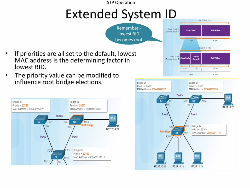
• If priorities are all set to the default, lowest MAC address is the determining factor in lowest BID.
• The priority value can be modified to influence root bridge elections.
STP Operation
Extended System IDRemember -lowest BID
becomes root

25© 2016 Cisco and/or its affiliates. All rights reserved. Cisco Confidential
3.2 Types of Spanning Tree Protocols
Varieties of Spanning Tree Protocols
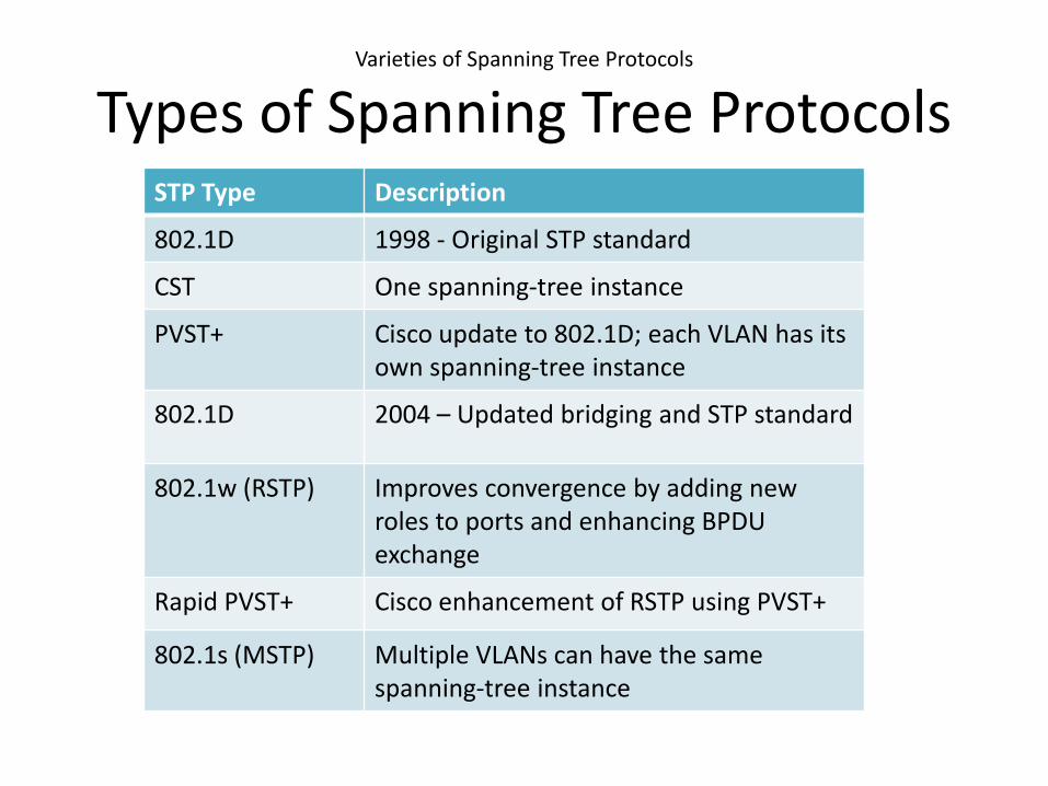
Types of Spanning Tree ProtocolsSTP Type Description
802.1D 1998 - Original STP standard
CST One spanning-tree instance
PVST+ Cisco update to 802.1D; each VLAN has its own spanning-tree instance
802.1D 2004 – Updated bridging and STP standard
802.1w (RSTP) Improves convergence by adding new roles to ports and enhancing BPDU exchange
Rapid PVST+ Cisco enhancement of RSTP using PVST+
802.1s (MSTP) Multiple VLANs can have the same spanning-tree instance

Varieties of Spanning Tree Protocols
Characteristics of Spanning Tree Protocols
STP Type Standard Resources Needed
Convergence Tree Calculation
STP 802.1D Low Slow All VLANs
PVST+ Cisco High Slow Per VLAN
RSTP 802.1w Medium Fast All VLANs
Rapid PVST+ Cisco Very high Fast Per VLAN
MSTP 802.1s Medium or high
Fast Per instance

Varieties of Spanning Tree Protocols
Overview of PVST+• Original 802.1D defines a common
spanning tree
– One spanning tree instance for the switched network (no matter how many VLANs)
– No load sharing
– One uplink must block for all VLANs
– Low CPU utilization because only one instance of STP is used/calculated
• Cisco PVST+ - each VLAN has its own spanning tree instance
– One port can be blocking for one VLAN and forwarding for another VLAN
– Can load balance
– Can stress the CPU if a large number of VLANs are used

Varieties of Spanning Tree Protocols
Port States and PVST+ OperationPort State
Operation allowed Blocking Listening Learning
Forwarding
Disabled
Can receive/process BPDUs
Yes Yes Yes Yes No
Can forward data frames received on an interface
No No No Yes No
Can forward data frames switchedfrom another interface
No No No Yes No
Can learn MAC addresses
No No Yes Yes No

Varieties of Spanning Tree Protocols
Extended System ID and PVST+ Operation
• The extended system ID field ensures each switch has a unique BID for each VLAN.
• The VLAN number is added to the priority value.– Example – VLAN 2 priority is 32770 (default
value of 32768 plus the VLAN number of 2 equals 32770)
– Can modify the priority number to influence the root bridge decision process
• Reasons to select a particular switch as root bridge– Switch is positioned such that most traffic
patterns flow toward this particular switch– Switch has more processing power (better
CPU)– Switch is easier to access and manage
remotely
Remember that the BID is a unique ID

Varieties of Spanning Tree Protocols
Overview of Rapid PVST+ • Rapid PVST+ speeds up STP
recalculations and converges quicker– Cisco version of RSTP
• Two new port types– Alternate port (DIS)– Backup port
• Independent instance of RSTP runs for each VLAN
• Netacad 3.2.1.3

Varieties of Spanning Tree Protocols
Edge Ports• Has an end device connected – NEVER another
switch
• Immediately goes to the forwarding state
• Functions similar to a port configured with Cisco PortFast
• Use the spanning-tree portfast command

33© 2016 Cisco and/or its affiliates. All rights reserved. Cisco Confidential
3.3 Spanning Tree Configuration
PVST+ Configuration
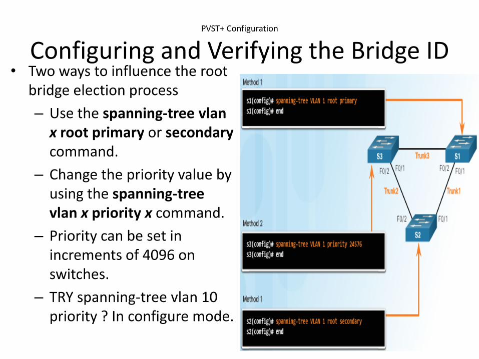
Configuring and Verifying the Bridge ID• Two ways to influence the root
bridge election process
– Use the spanning-tree vlanx root primary or secondary command.
– Change the priority value by using the spanning-tree vlan x priority x command.
– Priority can be set in increments of 4096 on switches.
– TRY spanning-tree vlan 10 priority ? In configure mode.
PVST+ Configuration
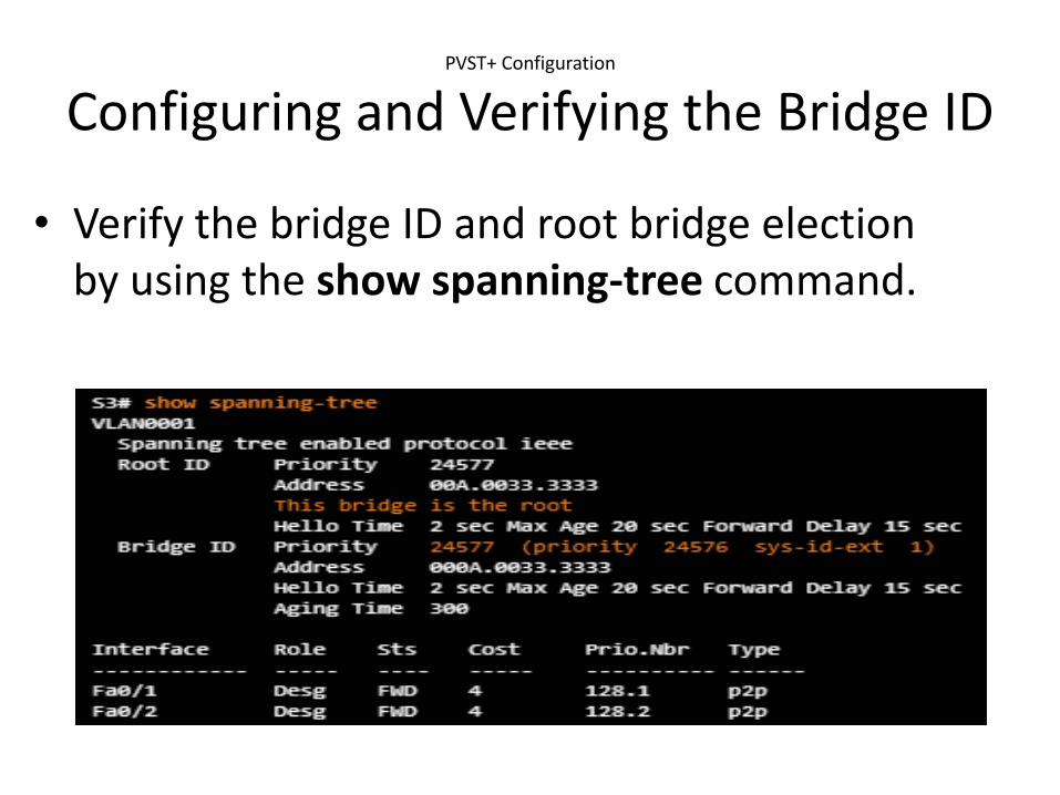
Configuring and Verifying the Bridge ID
• Verify the bridge ID and root bridge election by using the show spanning-tree command.

PVST+ Configuration
PortFast and BPDU Guard• PortFast is a Cisco feature for PVST+
environments. When a switch port is configured with PortFast that port transitions from blocking to forwarding state immediately, bypassing the usual 802.1D STP transition states (the listening and learning states).
• You can use PortFast on access ports to allow these devices to connect to the network immediately, rather than waiting for IEEE 802.1D STP to converge on each VLAN. Access ports are ports which are connected to a single workstation or to a server.

PVST+ Configuration
PortFast and BPDU Guard• In a valid PortFast
configuration, BPDUs should never be received, because that would indicate that another bridge or switch is connected to the port, potentially causing a spanning tree loop.
• Cisco switches support a feature called BPDU guard. When it is enabled, BPDU guard puts the port in an errdisabled (error-disabled) state on receipt of a BPDU. This will effectively shut down the port.

PVST+ Configuration
PortFast and BPDU Guard• PortFast is used on ports that have end
devices attached.
– Puts a port in the forwarding state
– Allows DHCP to work properly
• BPDU Guard disables a port that has PortFast configured on it if a BPDU is received

PVST+ Configuration
PVST+ Load Balancing
OR
OR

Rapid PVST+ Configuration
Spanning Tree Mode• Rapid PVST+ supports RSTP on a per-VLAN
basis.
– Default on a 2960 is PVST+.
– The spanning-tree mode rapid-pvst puts a switch into Rapid PVST+ mode.
– The clear spanning-tree detected-protocols privileged mode command is used to clear STP.