switch 8 x oc/ 8 relay dmx - pxm.plpxm.pl/resources/documents/px257_m_en_1-0.pdf · interpretation...
TRANSCRIPT

Manual
Switch8 x OC/
8 Relay DMX
PX257
R

Manufacturer reserves the right to make modifications in order to improve device operation.
PXM ul.. Przemys³owa 1230-701 Kraków, Poland
tel.: 626 46 92fax: +48 12 626 46 94E-mail: [email protected]: www.pxm.pl
+48 12
CONTENTS
3
3
4
5
5
5
6
6
6
7
8
9
9
9
10
12
12
13
1. General description.............................................................................................
2. Safety conditions.................................................................................................
3. D ...........................................
4. .................................................................................
4.1. ...................................................................
4.2. ...................................................................................
4.3 ..................
4.4 P ....................................
4.4.1. .................................................................
4.4.2. ...........
4.4.3. .................................................
4.5. Individual parameters programming (menu Ind)
5. ..................................................................................
6.
7.
9. Declaration of conformity.....................................................................................
escription of the connectors and control elements
Device programming..........
Button features................
Menu scheme.
DMX channel value for the output turning on and off........
rogramming group parameters (menu ALL)
DMX address...
Reaction of the device to DMX signal interruption.
Complementary outputs..
Reversed characteristic......
................................
DMX signal connection......
Connection scheme
Technical data
Dimensions
4.4.4. ..............................................
.............................................................................................
.....................................................................................................
8. ..........................................................................................................
Ver. 1.0.
3
The PX257 is a device manufactured in two versions: 8 Relay Module or OC Switch
8x1.3A. The product is used to switch on and off the stage effects and architectural illumination
using DMX-512 protocol. The module contains a set of 8 relays that control on / off type outputs.
The OC version of PX257 is an 8-channel, digital electronic link with a maximum DC
load switching one circuit of 1.3A. In 8 Relay Module version the devices' menu allows you to
program the DMX address for all output channels, and set to control the characteristics of an
electric motor.
In both versions of the device is designed for mounting on standard DIN rails in electrical
switchgear.
1. GENERAL DESCRIPTION
2. SAFETY CONDITIONS
The PX257 is a device powered with safe voltage 12-24 V; however, during its
installation and use the following rules must be strictly observed:
1. The device may only be connected to the 12-24V DC power supply (stabilized voltage) with
current-carrying capacity compatible with technical data.
2. All conductors should be protected against any mechanical and thermal damage.
3. In case of any wire damaging, it should be replaced with one of the same parameters.
4. Connection of DMX signal should be made only shielded conductor.
5. All repairs or wire connection can only be made with power supply disconnected.
6. In case of connecting output relays to 230V mains You should be double cautious because of
the risk of getting electrocuted (applies to PX257-RE).
7. PX257 should be strictly protected against contact with water and other liquids.
8. The device cannot be turned on in places with humidity exceeding 90%.
9. The device cannot be used in places with temperature lower than +2°C or higher than +40°C.
10. For cleaning use only a damp cloth.

4
3. DESCRIPTION OF THE CONNECTORS AND CONTROL ELEMENTS
DMX-512output
Display
Controlbuttons
Power supplyDMX-512
input
Outputs controldiodes
DMX signalcontrol diode
Outputs
b) “ " OC version of PX257
a) "Relay" version of PX257
DMX-512output Power supply
DMX-512input
Outputs

4.1. BUTTON FEATURES
4. DEVICE PROGRAMMING
- goes back to the previous MENU level or discards changes made,- scrolls to the previous feature on the same MENU level or decreases the
parameter's value- scrolls to the next feature on the same MENU level or increases the
parameter's value,- enters the next MENU level and confirms changes made,
escapeprevious
next
enter
After switching on the display of the device shows the version of the program To go to the main
menu, press ENTER and on the display will appear . Press the PREVIOUS or NEXT to
select the menu for programming ( ) and press ENTER to confirm.
.
4.2. MENU SCHEME
enter enter
next
next
next
next
next
enter
next
enter
next
next
enter
next
enter
next
next
enter
enter enter
next
enter
next
next
next
enter
next
next
enter
enter
next
5

6
Programming in this menu is common to all channels. After selecting from the main menu
press ENTER button to confirm, then using NEXT or PREVIOUS buttons select parameters you
want to set:
- DMX address,
- response of the unit to the DMX signal loss,
- Enable or disable the complementary outputs,
- Enable or disable reversed characteristic,
and then confirm your selection by pressing ENTER.
4.4. PROGRAMMING GROUP PARAMETERS (MENU ALL)
Enabling of the output occurs when passing DMX value of 141. Disable of the output follows
passing back (from higher value) DMX value of 115.
4.3. DMX channel value for the output turning on and off.
4.4.1. DMX address
In this menu you can change DMX address assignment to available channels.
To change it you need to select in menu and confirm your choice by pressing
ENTER. Using NEXT or PREVIOUS buttons you can set the desired DMX address selecting a
value from 1 to 512 and pressing ENTER. This address will be assigned to the first channel, the
next channels will be assigned following DMX addresses. After such assignment (to address 1)
the eight channel will be addressed with no. 8. Select another parameter to set or press the
ESCAPE back to the main menu.
Programmed in such way DMX address erases previous individual settings for each channel.

4.4.2. Reaction of the device to DMX signal interruption
After you select in menu confirm your choice by pressing ENTER. Using NEXT or
PREVIOUS buttons select a desired option and press ENTER.
- programs available in the menu;
- a scene that can be programmed;
- switching on all outputs,
- switching of all outputs
To set up the program, go to the menu by pressing the ENTER button and select using
NEXT or PREV buttons desired program ( ), confirm the choice by pressing ENTER.
7
Principle of operation programs can be observed both on the outputs connected to PX257 and
the LEDs that are located above display.
all outputs and LEDs are switched on and blink at the same time.
outputs and LEDs are blinking alternately in the two groups, the first group is outputs
1-4, and the second group to inputs 5-8.
outputs and LEDs are blinking one after the other, Once one goes out another turns on
in the direction from the output No. 1 to output No. 8.
output and LEDs are blinking one after the other, Once one goes out another turns on in
the direction from output No. 8 to output No. 1.
this option allows us to adjust the speed of the scene from 0.1 sec to 60 sec.
To set the speed of the scene, go to the menu approving with ENTER button in the selected
program, press ENTER and press NEXT or PREV to set appropriate value for the speed, any
changes will be visible on the outputs as well as the control LEDs for each channel. You need to
approve the changes with the Enter button.
allows you to select a static scene, what means to choose outputs to be activated in the
absence of DMX signal.
To select all outputs responsible for a static scene, press the ENTER button on the
menu, then use the NEXT or PREV button to set the chosen input marked as Ou1 - Ou8 and press
ENTER. Subsequently you need to set using NEXT or PREV buttons to a value indicating
the inclusion of one of the outputs or to disable the output. Repeat the procedure to set all
outputs as expected.
eeeee
SET
CLR
This feature is used not only to protect the installation from DMX signal interruption, but also to control the outputs without the external controller. After the feature is programmed, when the DMX signal is not present, the module will realize the selected function independently. When the DMX signal is connected again, the module stops playing the function and starts working according to the commands transmitted through the DMX line.

8
The device is equipped with complementary output option. For PX257 "Relay" version this
function allows you to start the mode in which the outputs work in pairs, where one in the pair is
turned on, and the other is off. The complementary pairs establish outputs 1-2, 3-4, 5-6 and 7-8.
The way the function works is described below. This function is used e.g. for controlling electric
motors.
To activate this option, go to the menu and then select a value.
1 -Once you switch on
all outputs
2 3 - 4
Once you switch off
all outputs
5 - 6 7 - 8Outputs number
on on on on
on on on on
off off off off
off off off off
4.4.3. Complementary outputs
In the case of DMX control device operates as follows:
where: on - above output number is onoff - above output number is off
1 -DMX signal
value >147
2 3 - 4
DMX signal
value <115
5 - 6 7 - 8Outputs number
on on on on
on on on on
off off off off
off off off off
Input DMXchannels 1 2 3 4
The table below shows the operation of the activated
function on the example of running option or .
complementary outputs
enter enter
next
next
next
enter
enter
next
WARNING! If you connect an electric motor it have to be connected to the paired outputs (e.g.
output 1 - phase 1 and output 2 - phase 2). Connecting the motor phases to the unpaired output
may result short circuit.
When you activate this feature you can change
the value of delay (it is adjustable from 0.1 to 5 s)
between switching off one of the outputs in the pair,
and the activation of the second.

4.5. INDIVIDUAL PARAMETERS PROGRAMMING (MENU Ind)
In this menu, you can set the DMX address individually for 8 outputs.
After selecting from the main menu, press ENTER to confirm.
Using PREVIOUS or NEXT buttons select the output that you want to set ( - ) and
press ENTER.
Then also using PREVIOUS or NEXT buttons select a value from 1 to 512, or to turn off the
output of DMX control and press ENTER.
9
5. DMX SIGNAL CONNECTION
CORRECT
120 Ohm
WRONG
DMX-512 input DMX-512 output DMX line DMX-512 input
TERMINATOR CONNECTION
PX257 is equipped with option of reversed read the value of DMX signal. If you run this function,
the device should interpret received DMX signal value of 0 as a signal about the value of the 255.
It works similarly with the other values.
4.4.4. Reversed characteristic
To activate this option, go to the menu
and then select a value.
enter enter
next
next
next
enter
next0
When feature is off
1 2 ... 254255Received DMX value
0 2 254
254 ... 0
1 ... 255
255 253 1
Inte
rpre
tatio
n
of
DM
X s
ignal
Sposób dzia³ania opcji przedstawia tabela poni¿ej:
PX257 have to be connected to DMX line in serial mode, with no branches on DMX control cable.
That means that DMX line, from the signal source, must be connected to DMX IN pins of PX257
and later, directly from DMX OUT pins to the next device in DMX chain. If the PX257 is the last
DMX chain receiver there should be terminator (resistor 120 Ohm) mounted between "DMX+"
and "DMX-" pins of DMX OUT section.
When feature is on

10
6. CONNECTION SCHEME
Caution!
NOT CONNECTED
DC LOAD max. 1,3 A
On next page you will find connection example for inductive loads
DC LOAD max. A 1,3
DC LOAD max. A 1,3
DMX-512 input DMX-512 output
To evenly load each of power supply dedicated pins connect power supply conductors (12 - 24V DC and GND one) to all suitable PX257 pins - according to diagram.
a) for "OC" version of PX257
DC LOAD max. A 1,3
DC LOAD max. A 1,3
DC LOAD max. A 1,3
DC LOAD max. A 1,3
DC LOAD max. A 1,3
POWERSUPPLY
Do
no
t o
verl
oad
th
e o
utp
uts
!

11
Each output in PX257 is a open collector, its inner construction is shown on picture below.
1,3
A
1,3
A
COM
OUT 3OUT 4
+_
loadpower supply
For inductive loads, use protection diode e.g. 1N4007
b) for "Relay" version of PX257
1 2 3 4 5 6
PX015
1 2 3 4 5 6 Chaser Scene
Club 6p
90
% 100
80
70
60
50
40
30
20
10
0
100 %
90
80
70
60
50
40
30
20
10
0
Maste
r
MusicSpeed
e.g. halogens
230 V ACN
L
DMX controler effect (e.g. lamp)
L N DC OKV V
power supply24V DC

12
105 mm
86 m
m
60 mm
8. DIMENSIONS
512
+12-24 V DC
130 mA for 24V DC
250 mA for 12V DC
8
max. 2A, 250 V AC / channel
terminal blocks
Yes
105 mm
60 mm
86 mm
max. 2A, 24 V DC / channel
max. 0.5A, 250 V AC / channel
max. 0.5A, 24 V DC / channel
max. 1.3A, 24 V DC / channel
600 cycles/h (for the nominal AC load)
- DMX channels
- load capacity of outputs (OC version)
- max. switching frequency
- power supply
- current consumption
- number of output channels
- load capacity of outputs (RE version)
resistance load
resistance load
induction load
induction load
- output sockets
- DMX output
- dimensions:
- width
- height
- length
7. TECHNICAL DATA
13
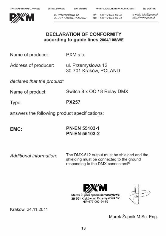
PXM s.c.
ul. Przemys³owa 1230-701 Kraków, POLAND
Switch 8 x OC /
PX257
PN-EN 55103-1PN-EN 55103-2
The DMX-512 output must be shielded and the shielding must be connected to the ground responding to the DMX connectorsP
Marek ¯upnik M.Sc. Eng.
8 Relay DMX
Name of producer:
Address of producer:
declares that the product:
Name of product:
Type: answers the following product specifications:
EMC:
Additional information:
Kraków, 24.11.2011
DECLARATION OF CONFORMITYaccording to guide lines 2004/108/WE
stage and theatre consoles digital dimmers dmx systems architectural lighting controllers led lighting
tel: +48 12 626 46 92fax: +48 12 626 46 94
e-mail: [email protected] http://www.pxm.pl
ul. Przemys³owa 1230-701 Kraków, POLAND