switch 7700 · pdf file · 2016-02-16connecting i/o module interface cables ......
TRANSCRIPT

Switch 7700 Installation Guide
http://www.3com.com/
Part No. 10014180
Published July 2003


Contents Chapter 1 About This Guide ............................................................................................................................. 7
1.1. Conventions ...................................................................................................................................................................7 Chapter 2 Overview .......................................................................................................................................... 9
2.1. Introduction to the 3Com Switch 7700 ...........................................................................................................................9 2.1.2. Modular Hardware Architecture ................................................................................................................................ 9 2.1.3. I/O Module Interfaces.............................................................................................................................................. 10 2.1.4. Software Features................................................................................................................................................... 10 2.1.5. Maintenance ........................................................................................................................................................... 10
Chapter 3 Switch 7700 Components.............................................................................................................. 11 3.1. Switch Chassis.............................................................................................................................................................11
3.1.2. Switch Backplane.................................................................................................................................................... 11 3.1.3. Fabric Module ......................................................................................................................................................... 12 3.1.4. Reset Button ........................................................................................................................................................... 12 3.1.5. Console port ........................................................................................................................................................... 12 3.1.6. Switching I/O Modules ............................................................................................................................................ 14 3.1.7. Power System......................................................................................................................................................... 19 3.1.8. Fan Assembly (3C16856) ....................................................................................................................................... 19 3.1.9. Switch Specifications .............................................................................................................................................. 19
Chapter 4 Preparing for Installation............................................................................................................... 23 4.1. Safety Information ........................................................................................................................................................23
4.1.1. General Safety Recommendations ......................................................................................................................... 23 4.1.2. Electrical Safety ...................................................................................................................................................... 23 4.1.3. Placement Safety.................................................................................................................................................... 23 4.1.4. Preventing Electrostatic Discharge Damage........................................................................................................... 24 4.1.5. Laser Safety............................................................................................................................................................ 24
4.2. Installation Site Requirements .....................................................................................................................................25 4.2.1. Temperature/Humidity ............................................................................................................................................ 25 4.2.2. Cleanliness ............................................................................................................................................................. 25 4.2.3. Anti-static ................................................................................................................................................................ 25 4.2.4. EMI Interference ..................................................................................................................................................... 26 4.2.5. Grounding ............................................................................................................................................................... 26 4.2.6. Installation Space.................................................................................................................................................... 26
4.3. Installation Tools ..........................................................................................................................................................27 Chapter 5 Installing Hardware ....................................................................................................................... 29
5.1. Installing the Chassis ...................................................................................................................................................29 5.1.1. Installing in a Standard Cabinet .............................................................................................................................. 29
iii

5.1.2. Installing on a Workbench....................................................................................................................................... 29 5.2. Installing a Card ...........................................................................................................................................................29
5.3. Connecting the Ground Wire........................................................................................................................................30
5.4. Connecting Power Cords .............................................................................................................................................30
5.5. Installing the Fan Assembly .........................................................................................................................................30
5.6. Connecting the Cables.................................................................................................................................................31 5.6.1. Console Cable ........................................................................................................................................................ 31 5.6.2. AUX cable............................................................................................................................................................... 32
5.7. Connecting I/O Module Interface Cables .....................................................................................................................33 5.7.1. Connecting Electrical Port Cables........................................................................................................................... 33 5.7.2. Connecting Fiber Connectors ................................................................................................................................. 34
5.8. Post-installation Checklist ............................................................................................................................................35 Chapter 6 Configuring and Booting Software ................................................................................................ 37
6.1. Configuration................................................................................................................................................................37
6.2. Setting Terminal Parameters .......................................................................................................................................37
6.3. Booting the Switch 7700 ..............................................................................................................................................41 6.3.1. Powering up and Booting........................................................................................................................................ 41
Chapter 7 Software Maintenance................................................................................................................... 45 7.1. BOOT Menu .................................................................................................................................................................45
7.2. Upgrading Software Using Xmodem............................................................................................................................46
7.3. Upgrading Software Using Ethernet.............................................................................................................................48 7.3.1. Upgrading Software Using TFTP ............................................................................................................................ 48 7.3.2. Upgrading Software Using FTP .............................................................................................................................. 49
7.4. Lost Passwords............................................................................................................................................................50 Chapter 8 Hardware Maintenance ................................................................................................................. 51
8.1. Replacing a Power Module ..........................................................................................................................................51
8.2. Replacing Cards...........................................................................................................................................................51
8.3. Replacing the Fan Assembly .......................................................................................................................................52 Chapter 9 System Troubleshooting................................................................................................................ 53
9.1. Troubleshooting the Configuration ...............................................................................................................................53 9.1.1. No information is displayed on the terminal ............................................................................................................ 53 9.1.2. The displayed characters are illegible..................................................................................................................... 53
9.2. Troubleshooting Power ................................................................................................................................................53
9.3. Troubleshooting the Fan ..............................................................................................................................................54
iv

9.4. Troubleshooting the Cards...........................................................................................................................................54 Chapter 10 Technical Support ....................................................................................................................... 55
10.1. Online Technical Services..........................................................................................................................................55 10.1.1. World Wide Web Site............................................................................................................................................ 55 10.1.2. 3Com Knowledgebase Web Services................................................................................................................... 55 10.1.3. 3Com FTP Site ..................................................................................................................................................... 55
10.2. Support from Your Network Supplier .........................................................................................................................56
10.3. Support from 3Com....................................................................................................................................................56 10.3.1. Email Support ....................................................................................................................................................... 56 10.3.2. Telephone Support ............................................................................................................................................... 56
10.4. Returning Products for Repair....................................................................................................................................58
v

Chapter 1 About This Guide
This guide describes the 3Com® Switch 7700 Ethernet switch and how to install hardware, configure and boot software, and maintain software and hardware. This guide also provides troubleshooting and support information for your Switch 7700 system.
1.1. Conventions
Table 1 and Table 2 list conventions that are used throughout this guide.
Table 1 Notice Icons
Icon Notice Type Description
Information note
Information that describes important features or instructions.
Caution
Information that alerts you to potential loss of data or potential damage to an application, system, or device.
Warning
Information that alerts you to potential personal injury.
Table 2 Text Conventions
Convention Description Screen displays This typeface represents information as it appears on the screen. Keyboard key names If you must press two or more keys simultaneously, the key names are linked with a plus sign (+), for
example: Press Ctrl+Alt+Del
The words “enter” and type”
When you see the word “enter” in this guide, you must type something, and then press Return or Enter. Do not press Return or Enter when an instruction simply says “type.”
Words in italics
Italics are used to: - Emphasize a point. - Denote a new term at the place where it is defined in the text. - Identify menu names, menu commands, and software button names. Examples: From the Help menu, select Contents. Click OK.
7

Chapter 2 Overview
2.1. Introduction to the 3Com Switch 7700
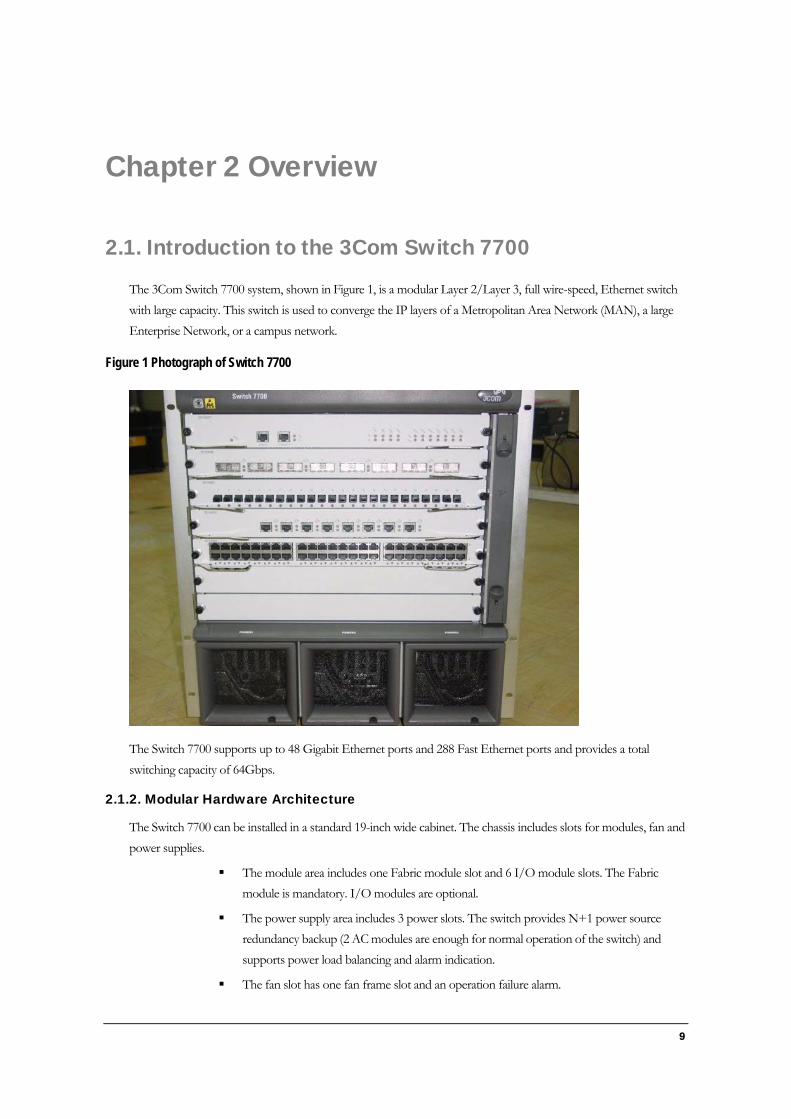
The 3Com Switch 7700 system, shown in Figure 1, is a modular Layer 2/Layer 3, full wire-speed, Ethernet switch with large capacity. This switch is used to converge the IP layers of a Metropolitan Area Network (MAN), a large Enterprise Network, or a campus network.
Figure 1 Photograph of Switch 7700
The Switch 7700 supports up to 48 Gigabit Ethernet ports and 288 Fast Ethernet ports and provides a total switching capacity of 64Gbps.
2.1.2. Modular Hardware Architecture
The Switch 7700 can be installed in a standard 19-inch wide cabinet. The chassis includes slots for modules, fan and power supplies.
The module area includes one Fabric module slot and 6 I/O module slots. The Fabric module is mandatory. I/O modules are optional.
The power supply area includes 3 power slots. The switch provides N+1 power source redundancy backup (2 AC modules are enough for normal operation of the switch) and supports power load balancing and alarm indication.
The fan slot has one fan frame slot and an operation failure alarm.
9

O V E R V I E W
2.1.3. I/O Module Interfaces
The Switch 7700 supports I/O modules that offer from 8 to 48 ports, as described in the following list:
8-port 1000BASE-X (GBIC) GE module (8GBIC) (3C16858)
8-port 10/100/1000BASE-T auto-sensing GE module (8BT) (3C16859)
24-port 100BASE-FX-MMF FE multi-mode fiber module (24FX) (3C16861)
48-port 10/100BASE-T auto-sensing FE module (48TX) (3C16860)
2.1.4. Software Features
The Switch 7700 software delivers complete networking solutions such as routing protocols, VLAN control, QoS and network management.
2.1.5. Maintenance
The Switch 7700 provides the following convenient maintenance functions:
Management options: Telnet, console, and remote modem dial-up
Fault diagnosis tools: port self-loop, port activating/de-activating
Hot swap support for fan, power, Fabric and I/O modules
Flexible software upgrades and online upgrades
10
Chapter 3 Switch 7700 Components
3.1. Switch Chassis
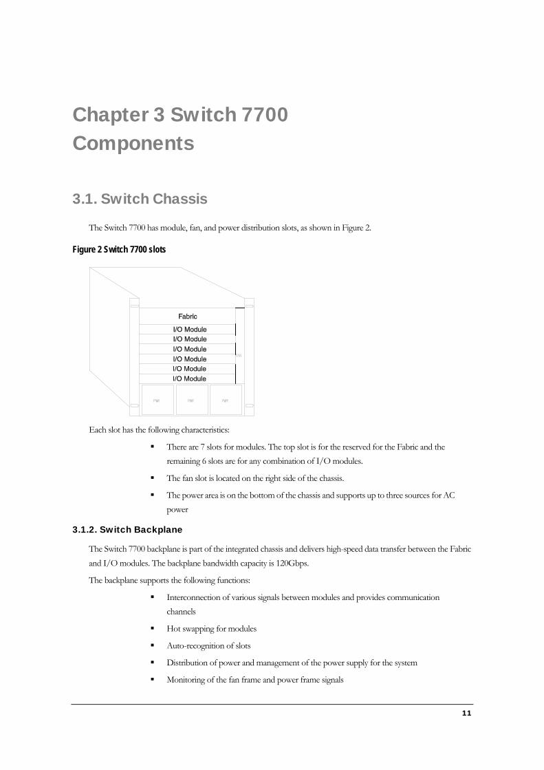
The Switch 7700 has module, fan, and power distribution slots, as shown in Figure 2.
Figure 2 Switch 7700 slots
Each slot has the following characteristics:
There are 7 slots for modules. The top slot is for the reserved for the Fabric and the remaining 6 slots are for any combination of I/O modules.
The fan slot is located on the right side of the chassis.
The power area is on the bottom of the chassis and supports up to three sources for AC power
3.1.2. Switch Backplane
The Switch 7700 backplane is part of the integrated chassis and delivers high-speed data transfer between the Fabric and I/O modules. The backplane bandwidth capacity is 120Gbps.
The backplane supports the following functions:
Interconnection of various signals between modules and provides communication channels
Hot swapping for modules
Auto-recognition of slots
Distribution of power and management of the power supply for the system
Monitoring of the fan frame and power frame signals
11
S W I T C H 7 7 0 0 C O M P O N E N T S
3.1.3. Fabric Module
The Fabric is the core of Switch 7700 system. It has the following functions.
Connects the I/O modules through the backplane and forwards Layer 2 and Layer 3 data
Manages and calculates routing
Fulfills the switch’s software upgrade and system reset functions
Monitors system power and the fan frame
A detailed description of Fabric attributes is provided in Table 3
Table 3 Fabric attributes
Item Fabric Module (3C16857) CPU MPC8260 BootROM 1MB SDRAM 128MB Flash 16MB Dimensions (L x W) 366.7mm x 340mm
External ports One console port, supporting local and remote dial-up configuration management of the switch. One 10BASE-T/100BASE-TX port for upgrade and network management
Maximum power consumption 80W
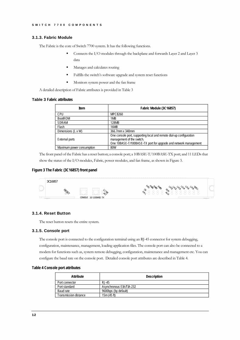
The front panel of the Fabric has a reset button; a console port; a 10BASE-T/100BASE-TX port; and 11 LEDs that show the status of the I/O modules, Fabric, power modules, and fan frame, as shown in Figure 3.
Figure 3 The Fabric (3C16857) front panel
3C16857
LI NKACTCONSOLE 10/ 100BASE- TX
RESETOK
FAI L
FAN PWR1PWR2 RUN
PWR3LPU1
LPU2LPU3
LPU4LPU5
LPU6SRPU
ALM
3.1.4. Reset Button
The reset button resets the entire system.
3.1.5. Console port
The console port is connected to the configuration terminal using an RJ-45 connector for system debugging, configuration, maintenance, management, loading application files. The console port can also be connected to a modem for functions such as, system remote debugging, configuration, maintenance and management etc. You can configure the baud rate on the console port. Detailed console port attributes are described in Table 4.
Table 4 Console port attributes
Attribute Description Port connector RJ-45 Port standard Asynchronous EIA/TIA-232 Baud rate 9600bps (by default) Transmission distance 15m (45 ft)
12

S W I T C H 7 7 0 0 C O M P O N E N T S
13
Attribute Description
Services supported Connect with character terminal Connect with local or remote PC serial port and run terminal emulator on PC (a pair of Modems are needed for remote connection)
10/100BASE-TX Ethernet Management Port
The Ethernet port can be connected to a computer using an RJ-45 connector for system application downloading and debugging. It can also be connected to devices such as a network management workstation for managing the system remotely. Detailed Ethernet port attributes are described in Table 5.
Table 5 Attributes of the 10/100BASE-T port
Attribute Description Port connector RJ-45 Number of port(s) 1
Port speed 10Mbps, half/full duplex 100Mbps,half/full duplex MDIX
Medium and maximum transmission distance Category-5 twisted pairs for transmission within 100m (300 ft)
Port function Switch software upgrade and network management
Table 6 describes the LEDs of the Ethernet ports.
Table 6 Description of the 10/100BASE-T port LEDs
Indicator State description
LINK Off — the line has not connected. Green — the line is connected.
ACTIVE Green — there is no data transmitted. Green Flashing — data is being transmitted or received.
Module LEDs
The MOD1 to MOD 6 LEDs show the state of the I/O modules, as described in Table 7.
Table 7 Description of module LEDs
Indicator State description
RUN Green/Off — the module fails to work or has not been inserted Green Flashing — the module works normally
ALM Off — the module works normally or has not been inserted Remaining green or green flashing — the module fails to work or something abnormal happened
Power Indicators
PWR1, PWR2, and PWR3 LEDs show the states of the power modules, as described in Table 8.
Table 8 Description of power LEDs
Indicator State description
OK Green — the corresponding power works normally. Off — the corresponding power fails to work or has not been installed.
FAIL Green — the corresponding power fails to work. Off — the corresponding power works normally or has not been installed.
Fan Indicator
FAN LEDs show the state of the corresponding fan frame, as described in Table 9.

S W I T C H 7 7 0 0 C O M P O N E N T S
Table 9 Description of fan LED
Indicator State description
OK Green — the fan works normally. Off — the fan fails to work or has not been installed.
FAIL Green — the fan fails to work. Off — the fan works normally or has not been installed.
3.1.6. Switching I/O Modules
The Switch 7700 provides 6 I/O modules slots below the Fabric (FAB64) slot. (See Figure 2-1). The Switch 7700 supports the following I/O modules:
8-port 1000BASEX (GBIC) GE module (8GBIC) (3C16858)
8-port 10/100/1000BASE-T GE module (8BT) (3C16859)
24-port 100BASE-FX MMF FE module (24FX) (3C16861)
48-port 10/100BASE-T auto-sensing FE module (48T) (3C16860)
Consider the following when selecting I/O modules:
You can configure several I/O modules of the same type
All 6 I/O module slots are the same and any combination of I/O modules can be inserted
You should select I/O module port cables that are compatible with each installed I/O module
48-port 10/100BASE-T Auto-sensing FE Card (48T) (3C16860)
The 48T module provides 48 external 100Mbps Ethernet electrical ports and is illustrated in Figure 4.
Figure 4 The 48-port 10/100BASE-T Auto-sensing FE Card
Table 10 describes the attributes of the 48TX module.
Table 10 Attributes of the 48-port 10/100BASE-T Auto-sensing FE Card
Attribute 48TX CPU MPC850 BootROM 512KB SDRAM 64MB Dimensions (L X W) 366.7mm x 340mm Maximum power consumption 55W Connector RJ-45 Quantity of port(s) 48
14

S W I T C H 7 7 0 0 C O M P O N E N T S
15
Attribute 48TX
Port transmission speed 10M half/full duplex 100M half/full duplex MDI/MDIX auto-sensing
Optional cables and maximum transmission distance The external cables are 4 Category-5 twisted pairs for transmission within 100m.
Compliance IEEE802.3 IEEE802.3u IEEE802.3x
Each 100M Ethernet port has a green LED, indicating LINK/ACTIVE states. Off means the line is disconnected. Green flashing means data is being transmitted or received. The 48T panel and LEDs are illustrated in Figure 5.
Figure 5 The 48T (3C16860) panel
3C16860
The 48T module requires two Category-5 twisted pairs of 100 ohm cable with an RJ-45 connector plug for transmission within 100 meters (300 feet).
8-port 1000BASEX (GBIC) GE Card (8GBIC) (3C16858)
The 8GBIC module provides 8 external Gigabit GBIC module ports. A GBIC module is used for each data receiving/transmitting channel. The following modules are available:
3CGBIC91
3CGBIC92
3CGBIC93
3CGBIC97
The 8GBIC module is illustrated in Figure 6.
Figure 6 The 8-port 1000BASEX (GBIC) GE Card
Table 11 describes the attributes of the 8GE module.

S W I T C H 7 7 0 0 C O M P O N E N T S
Table 11 Attributes of the 8-port 1000BASEX (GBIC) GE Card
Attribute 8GBIC CPU MPC850 BootROM 512KB SDRAM 64Mb Dimensions (L x W) 366.7mm x 340mm Maximum power consumption 50W Quantity of GBIC port(s) 8
Optional GBIC module types 3CGBIC 91 3CGBIC 92 3CGBIC 93 3CGBIC 97
Port transmission speed 1000Mbps, full duplex
Compliance IEEE 802.3z IEEE 802.3x
Every 8GBIC port has a green LED, as shown in Figure 7.
Figure 7 The 8-port 1000BASEX (GBIC) GE module panel
3C16858
Table 12 describes the states of the LED.
Table 12 Description of the 8-port 1000BASEX (GBIC) GE module LED
Indicator State description Green (LINK) — The port is connected to another port Off (LINK) — The port has not been connected to any other port LINK/ACT Green Flashing — Data is being transmitted or received via the port.
The cables for each of the supported 8GBIC modules are described in Table 13.
Table 13 Description of the module port cables GBIC Module Type Central Wave Length Connector Type Fiber Interface
Specifications Transmission Distance
3CGBIC91 850 nm SC 50/125 mm Multimode Fiber
550 meters
3CGBIC92 1550nm SC 9/125 mm Single Mode Fiber
10 Km
3CGBIC93 N/A RJ-45 Cat 5E UTP 100 meters 3CGBIC97 1550nm SC 9/125mm Single
Mode Fiber 70 Km
8-port 10/100/1000BASE-T GE Card (8BT) (3C16861)
The 8BT module, shown in Figure 8, provides 8 external 10/100/1000Mbps auto-sensing Ethernet electrical ports.
16

S W I T C H 7 7 0 0 C O M P O N E N T S
Figure 8 The 8-port 10/100/1000BASE-T GE Card
Attributes of the 8BT module are described in Table 14.
Table 14 Attributes of the 8BT (3C16859) module
Attribute 8BT I/O module (3C16859) CPU MPC850 BootROM 512Kb SDRAM 64MB Dimensions (L x W) 366.7mm x 340mm Maximum power consumption 50W Connector type RJ-45 Number of port(s) 8
Port transmission speed 10Mbps, half/full duplex 100M bps, half/full duplex 1000M bps, full duplex
Optional cables and maximum transmission distance
4 Category-5 non-shielded twisted pairs serve as external cables. The resistance value of each pair is 100 ohm. The cable has a maximum transmission distance of 100m.
Compliance IEEE 802.3ab IEEE802.3 IEEE802.3u IEEE802.3x
Each port on the 8BT module has 2 LEDs, as shown in Figure 9.
Figure 9 The 8-port 10/100/1000BASE-T GE module panel
3C16859
Table 15 describes the LEDs on the 8BT module.
Table 15 The 8-port 10/100/1000BASE-T GE module LEDs
Indicator State description
LINK Off — the link is not connected Green — the link is connected
ACT Off — there is no data being transmitted The LED blinks when data is being transmitted or received
The 8BT module requires four Category-5 unshielded twisted pairs of 100 ohm cable with RJ-45 connectors for transmission within 100 meters (300 yards).
24-port 100BASE-FX MMF FE Card (24FX)
The 24FX module, shown in Figure 10, provides 24 100M multi-mode Ethernet optical port service channels.
17

S W I T C H 7 7 0 0 C O M P O N E N T S
Figure 10 The 24-port 100BASE-FX MMF FE module
Table 16 describes the attributes of the 24 FX module.
Table 16 Attributes of the 24-port 100BASE-FX MMF FE module
Attribute 24FX (3C16861) CPU MPC850 BootROM 512KB SDRAM 64Mb Dimensions (L x W) 366.7mm x 340mm Maximum power consumption 55W Connector type MT-RJ Number of ports 24 Port transmission speed 100Mbps, full-duplex Optional cables and maximum transmission distance
24FX: 62.5/125µm multi-mode optical fiber is used for transmission within 2km.
Compliance IEEE 802.3 IEEE 802.3i IEEE 802.3u IEEE 802.3x
Each 100M optical port has a green LED, as shown in Figure 11.
Figure 11 The 24FX (3C16861) panel
3C16861
Table 17 describes the states of the FX24 module LEDs.
Table 17 Description of the 24FX (3C16861) LEDs
Indicator State description Green (LINK) — The port has been connected with another port properly. Off (LINK) — The port has not been connected with any other port. LINK/ACT Green Flashing (ACT) — There are data being transmitted or received on the port.
1-24 Ethernet port numbers on the module
Table 18 describes characteristics of the 24FX cable.
18

S W I T C H 7 7 0 0 C O M P O N E N T S
Table 18 Description of the 24FX (3C16861) port cable
Card type Central wavelength Connector type Interface cable Transmission
distance 24FX 850nm MT-RJ 62.5/125µm multi-mode optical fiber 2km
3.1.7. Power System
Two power modules are sufficient to power a fully loaded Switch 7700 system. However, the switch provides 3 slots of power modules to implement N+1 redundancy backup.
The power distribution box of Switch 7700 is installed on the chassis floor close to the back of the chassis. It controls current connection, disconnection and distribution.
AC Power Module (3C16854)
The AC power source requires an AC power module and an AC distribution box.
The AC power module is connected to the external power source through an AC socket and is connected to the backplane. Specifications for the AC power module are listed in Table 19.
Table 19 AC power module specifications
Item AC power module AC input 100V to 240V, 47 to 63Hz Maximum output power 460W
3.1.8. Fan Assembly (3C16856)
The fan assembly, shown in Figure 12, is installed on the right side of the Switch 7700. There are 4 120mm fans to cool the system. The fans are directly connected to the backplane through connectors. Operation fault signals are collected and transmitted to the system alarm board through the backplane.
Figure 12 Fan Assembly (3C16856)
3.1.9. Switch Specifications
This section provides detailed information about features of the Switch 7700. Table 20 below describes system specifications for the Switch 7700.
19

S W I T C H 7 7 0 0 C O M P O N E N T S
20
Table 20 Switch 7700 system specifications
Item Switch 7700 Dimensions (W x H x D) 436mm x 486.2mm x 480mm (17in x 19in x 19 in) Weight (with all the components installed) 70Kg (154 lbs) Fabric 1 Fabric slot
I/O Modules
Optional types include: 8-port GBIC GE electrical port (8GBIC) 8-port GE electrical port (8BT) 48-port 100M Ethernet electrical port (48TX) 24-port 100M multi-mode Ethernet optical port (24FX)
System switching capacity 64Gbps System packet processing capacity 48Mpps Input voltage AC: 100V to 240V, 47 to 63Hz System maximum power consumption (with all the components installed) 650W
Operation environment temperature 0 to 40 0C (32 to 104 0F) Operation environment humidity 5% to 85%
Table 21 below describes service features of the Switch 7700.
Table 21 Switch 7700 service features
Service Support
Wire speed Layer 2 switching Switching capacity of 64Gbps Packet forwarding rate at 48Mpps Wire speed forwarding (with forwarding delay less than 10µs) for I/O Module ports
Port auto-negotiation Speed and duplex operation modes. Switching mode Store and Forward mode
MAC address table Address self-learning Complies with IEEE 802.1D standard and supporting port lock. Address table: up to 32K MAC (Media Access Control) address
STP/RSTP Complies with IEEE 802.1D/802.1w Standard
Traffic control IEEE 802.3x traffic control (full duplex) Back-pressure Based Flow Control (half-duplex)
Link aggregation 8-port GBIC GE optical module (8GBIC) and 8-port GE electrical module (8BT), up to 8 ports 48-port 100M Ethernet electrical I/O Module (48TX), 24-port 100M multi-mode Ethernet optical port I/O Module (24FX), up to 24 ports.
VLAN
4K VLANs, complies with IEEE 802.1Q standard Port-based VLAN GARP (Generic Attribute Registration Protocol) and GVRP (GARP VLAN Registration Protocol) Routing between VLANs
Broadcast storm suppression Supported
Network protocol TCP/IP stack ARP (Address Resolution Protocol) DHCP Relay (Dynamic Host Configuration Protocol Relay)
IP address table Up to 64K IP address forwarding entries
IP routing Static routing RIP (Routing Information Protocol) Version 1 and 2 OSPF (Open Shortest Path First) Version 2
Multicast GMRP (GARP Multicast Registration Protocol) IGMP (Internet Group Management Protocol) PIM-DM (Protocol Independent Multicast-Dense Mode) PIM-SM (Protocol Independent Multicast-Sparse Mode)

S W I T C H 7 7 0 0 C O M P O N E N T S
21
Service Support
AAA and Security
Access user authentication complies with IEEE 802.1x Local authentication and RADIUS authentication User hierarchical management and password protection ACL (Access Control List), L2/L3/L4 information filtration (including frame filtration based on port and source/destination MAC address, packet filtration based on source/destination IP address and type of the upper layer protocol etc.) Plain text and MD5 text authentication for OSPF and RIP Version 2. Authentication for SNMP (Simple Network Management Protocol) Version 3.
Reliability VRRP (Virtual Router Redundancy Protocol)
QoS
Traffic classification Bandwidth management based on port, MAC address, IP address, TCP/UDP port number, ToS (Type of Service)/Diffserv value and CAR (Committed Access Rate). The granularity of bandwidth management is 64kbps. Priority-based on VLAN port, IEEE 801.1P and ToS/Diffserv. Support traffic classification to set CoS (Class of Service) 8 egress queues for each port Queue dispatching algorithm FIFO (First In First Out) and PQ (Priority Queuing).
Load and upgrade system software
Xmodem protocol. FTP (File Transfer Protocol) and TFTP (Trivial File Transfer Protocol)
System configuration/ System management
CLI (Command Line Interface) configuration mode. Configuration via console port Local/remote configuration via Telnet Remote configuration through dial-up via Modem Group 1, 2, 3 and 9 MIB of RMON (Remote Monitor) System log Hierarchical alarms
System maintenance Alarm/debugging information filter, output and statistics Maintenance and diagnosis tools, such as Ping and Tracert etc. Remote maintenance through Modem dial-up and Telnet login.


Chapter 4 Preparing for Installation
This chapter describes safety, site requirements, and tools for your Switch 7700 installation.
4.1. Safety Information
Please follow local safety regulations when performing any operation with the Switch 7700. Follow the related safety information and special safety instructions provided by 3Com. 3Com bears no responsibility for accidents that occur due to violations of safe operation requirements.
Only trained and qualified personnel should install and maintain 3Com products.
4.1.1. General Safety Recommendations
Before beginning the installation of the Switch 7700, review these general safety requirements:
Turn OFF all the power and remove all the power cords before opening the chassis.
Keep the chassis clean and dust-free.
Keep the chassis and installation tools away from high traffic areas.
Do not wear loose clothing, jewelry or other objects that could get caught in the chassis when you install and maintain the switch.
Wear safety glasses when working under any conditions that might be hazardous to your eyes.
Do not perform any action that creates a potential hazard to people or makes equipment unsafe.
4.1.2. Electrical Safety
To maintain electrical safety, review the following requirements:
Look carefully for possible hazards in your work area, such as ungrounded power extension cables, missing safety grounds, and moist floors.
Locate the emergency power-off switch in the room where you are working. Shut the power off at once in case an accident occurs.
Unplug all the power cords and external cables before moving the chassis.
Never assume that power is disconnected from a circuit. Always check.
Do not place the switch in a damp environment.
4.1.3. Placement Safety
Be sure to use caution when moving the Switch 7700. Consider the following requirements when moving the switch:
23

P R E P A R I N G F O R I N S T A L L A T I O N
Do not move the switch alone. Work with another person.
Move the switch slowly. Never move suddenly or twist your body.
Always disconnect all external cables (including power cord) before lifting or moving the chassis.
Do not hold the power handles when carrying the switch.
Do not put fingers into the vent of the chassis when carrying the switch.
Since the power handles and vent have not been designed to bear the weight of the entire chassis, it may damage the switch or even the personnel when carrying the switch.
4.1.4. Preventing Electrostatic Discharge Damage
To prevent components from being damaged by electrostatic discharge (ESD), take anti-static measures for the area where the switch is located and note the points below:
For safety, check the resistance value of the anti-static strap that is shipped with the Switch 7700. The resistance value should be between 1 and 10 megohm (Mohm).
Always wear an anti-static wrist strap when installing the parts, especially the electronic printed circuit boards, of the switch.
Grasp only the edge of the circuit board. Do not touch the components or the electric printed circuit.
Avoid contact between the electric printed circuit board and your clothing. The anti-static wrist strap protects only the board from electrostatic damage on the body.
To put on the anti-static wrist strap:
1. Put your hand through the wrist strap
2. Tighten the strap to insure that it makes complete contact with your skin
3. Connect the anti-static wrist strap to the grounding pole of the switch chassis with the alligator clip, as shown in Figure 13.
Figure 13 Wearing an anti-static wrist strap
Grounding
4.1.5. Laser Safety
Some I/O modules on the Switch 7700 have optical ports. If no optical connector is connected to the optical ports or if the dust-proof cover has been removed, there might be invisible laser radiation emitted from the port.
Caut on: The laser can hurt your eyes. Do not stare into an open optical port. i
24

P R E P A R I N G F O R I N S T A L L A T I O N
25
4.2. Installation Site Requirements
The Switch 7700 can only be used indoors. To ensure that the switch works normally and to expand its service life, the installation environment should meet the requirements in the next section, Temperature/Humidity.
4.2.1. Temperature/Humidity
To ensure the normal operation and service life of the switch, a controlled level of temperature and humidity should be maintained in the equipment room. If the humidity in the equipment room is too high for a long time, it will lead to degradation of the insulating material. Under these conditions, some metal parts can rust. If the relative humidity is too low, the captive screws may loosen and the insulation washers can shrink.
In addition, electrostatic discharge is likely to be produced in a dry environment, which jeopardizes the CMOS circuit of the switch. The higher the temperature, the greater the damage it will do to the switch. High temperature for a long time will speed the aging process of the insulation materials, reduce the reliability of the switch, and affect its service life.
4.2.2. Cleanliness
Dust can impact the normal operation of the switch. If dust accumulates on the chassis, it can cause electrostatic adsorption, resulting in the poor contact of the connector or metal contact point. This happens more frequently when the relative indoor humidity is low, which not only shortens the service life of the switch, but also causes system failure. The required specifications on dust content and particle diameter in an equipment room is shown in Table 22.
Table 22 Equipment room dust specifications Maximum diameter (µm) 0.5 1 3 5 Maximum intensity (particles per cubic meter) 1.4 x 10⁷ 7 x 10⁵ 2.4 x 10⁵ 1.3 x 10⁵
In addition to requirements about dust, rigorous requirements on the air content of salts, acids and sulfides in an equipment room are also set. These harmful gases speed metal corrosion and the aging process of some parts. The equipment room should be protected from the invasion of harmful gases such as SO2, H2S, NO2, NH3 and Cl2. The value limits of these gases are shown in Table 23.
Table 23 Harmful gas limits in an equipment room
Gas Average (mg/m3) Maximum (mg/m3) SO2 0.2 1.5 H2S 0 0.03 NO2 0.04 0.15 NH3 0.05 0.15 Cl2 0.01 0.3
4.2.3. Anti-static
Although anti-static measures have been considered, electrostatic discharge is a threat and damages the electric circuit and, possibly, the equipment.
Electrostatic induction comes from the external electric field (such as high-voltage electricity transmission cable and lightning) and the internal system (including the indoor environment, floor material and the whole equipment structure). To avoid electrostatic damage, consider the following requirements:

P R E P A R I N G F O R I N S T A L L A T I O N
26
Be sure the equipment and the floor are well connected to the earth ground.
Keep the room dustproof.
Maintain suitable temperature and humidity.
Wear an anti-static wrist strap and work clothes touching the circuit board with any part of your body.
4.2.4. EMI Interference
The installation of the switch can be affected by electromagnetic interference (EMI) sources. The interference from both inside and outside the equipment or the system affects the equipment in two ways: radiated interference and conducted interference.
Electromagnetic wave interference in the air is called radiated interference. Electrical coupling, magnetic coupling and electromagnetic coupling are conducted interference.
To prevent EMI interference:
Adopt effective measures to reduce the interference on a switch caused by the power supply system
Separate the working ground of the switch from the ground device of the power supply equipment or lightning-protection ground device as much as possible
Keep the switch far away from high-frequency devices working in high currents
Use electromagnetic shielding, filter and reduce grounding resistance when necessary
4.2.5. Grounding
A good grounding system is necessary for a switch to work reliably and the important guarantee of lightning protection, anti-interference and anti-static. You should provide a grounding system for the switch to insure that:
Contact resistance of the grounding bar is less than 0.1 ohm (it must pass the test of 12V/25A)
The grounding resistance value of the equipment room is less than 1 ohm
The ground wire PGND is composed of alternated green and yellow wires. The sectional area of the grounding wire cannot be smaller than 25mm2. The ground wire shall be kept as short as possible during the project construction
Preventive measures have been taken to prevent erosion of the grounding bar
The grounding bar is fixed with combined screws to avoid loosening
4.2.6. Installation Space
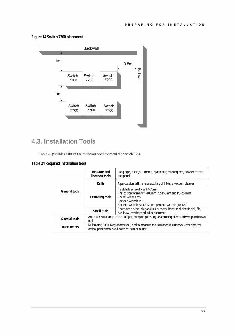
The Switch 7700 is a complex piece of equipment so it is necessary to make arrangements for the installation position, power supply, and cabling, as shown in Figure 14.
For better heat dissipation and equipment maintenance, 3Com recommends that you keep the front and back of the switch more than 1 meter away from the walls or other devices. The sides of the switch should be at least 0.8 meters away from the walls. If the optional cabinet is installed, the clear height of room should be more than 3 meters, inclusive.
P R E P A R I N G F O R I N S T A L L A T I O N
Figure 14 Switch 7700 placement
4.3. Installation Tools
Table 24 provides a list of the tools you need to install the Switch 7700.
Table 24 Required installation tools
Measure and lineation tools
Long tape, ruler (of 1 meter), gradienter, marking pen, powder marker and pencil
Drills A percussion drill, several auxiliary drill bits, a vacuum cleaner
Fastening tools
Flat-blade screwdriver P4-75mm Phillips screwdriver P1-100mm, P2-150mm and P3-250mm Socket wrench M5 Box-end wrench M6 Box-end wrenches (10-12) or open-end wrench (10-12)
General tools
Small tools Sharp-nose pliers, diagonal pliers, vices, hand-held electric drill, file, handsaw, crowbar and rubber hammer
Special tools Anti-static wrist strap, cable stripper, crimping pliers, RJ-45 crimping pliers and wire punchdown tool
Instruments Multimeter, 500V Meg-ohmmeter (used to measure the insulation resistance), error detector, optical power meter and earth resistance tester
27

Chapter 5 Installing Hardware
This chapter describes how to install the components of the Switch 7700.
5.1. Installing the Chassis
You can install the Switch 7700 in a standard, 19-inch cabinet or on a workbench.
5.1.1. Installing in a Standard Cabinet
Before you install the Switch 7700 in a standard cabinet, verify that:
The cabinet has been well built
The installation position for the switch has been well arranged
There are no obstacles
The switch is ready for installation and has been carried to a place near the cabinet
1. Have two people carry the switch to the front of the cabinet.
2. Put the switch on the tray or the guides and push it into the cabinet.
3. Fix the switch in the cabinet with the combination screw and floating nuts that are shipped with the delivery accessories.
5.1.2. Installing on a Workbench
Before you install the Switch 7700 on a workbench, verify that:
The workbench is firm enough to hold the switch and cables
There are no obstacles around the workbench
The switch is ready for installation and has been carried to a place near the workbench
1. Have two people carry the switch at both sides to the place in front of the workbench.
2. Carry the switch a little higher than the workbench and lower it onto the workbench gently.
5.2. Installing a Card
To install a module:
1. Wear an anti-static wrist strap
2. Remove the blank filler panel from the chassis slot and save it for future use
3. Hold the ejector levers of the module with both hands and push them outward
4. Align the module with the guides in the chassis and slide it gently into the slot
5. Push the module until the positioning pin on its handle bar touches the hole in the chassis
6. Push the ejector levers inward and push the handle bar pin into the positioning hole in the chassis
29

I N S T A L L I N G H A R D W A R E
7. Fasten the module’s captive mounting screws into the holes in the chassis with a screwdriver
5.3. Connecting the Ground Wire
Generally, the cabinet has a grounding bar. The ground wire of the switch can be connected to the grounding bar of the cabinet.
To connect the ground wire:
1. Remove the screw from the grounding hole in the switch chassis.
2. Set the ground wire connector around the grounding screw.
3. Fasten the grounding screw in the hole on the chassis.
4. Connect the other end of the ground wire to the grounding bar of the switch.
Warning: For the safety of personnel and equipment, the switch must be well grounded. The resistance between switch chassis and the ground should be less than 1 ohm.
5.4. Connecting Power Cords
To connect the AC power cord:
1. Plug the AC power cord into the socket in the switch and hook the cord plug.
2. Plug the other end into a socket strip with surge protector. Connect the strip to the AC power source in the room, as shown in Figure 15.
Figure 15 AC power cord connection
Grounding screw
Mousing-hook
AC power socket
Warning: For surge protection, the AC power should be led through an external protection device into the
Switch 7700.
5.5. Installing the Fan Assembly
1. Wear the anti-static wrist strap and take out the fan frame from the pack.
30

I N S T A L L I N G H A R D W A R E
2. Hold the ejector levers on the fan frame with both hands and push them outward. Align the fan with the guides in the chassis and slide it gently into the slot. Push the I/O Module until its positioning pin touches the hole in the chassis.
3. Push the ejector levers inward and push the handle bar pin into the hole in the chassis.
Warning: For safety, do not touch any part of the product that is labeled with dangerous voltage labels.
5.6. Connecting the Cables
This section describes how to connect console and AUX cables to the Switch 7700.
5.6.1. Console Cable
The console cable is an 8-core shielded cable. One end of the cable has a crimped RJ-45 connector, which is plugged into the console port of the switch. The other end has both a DB-9-hole connector and a DB-25-hole connector for connection to a 9- or 25-hole serial port at the configuration terminal. Figure 16 illustrates the console cable and connectors.
Figure 16 The console cable
Enlarged A Pos.
A
DB 25 8P8C
Enlarged B
Pos. Pos.
DB9 Enlarged C
Pos.
Pos.
CPos.
B
Table 25 Console cable pin-outs
RJ-45 Signal Direction DB-25 DB-9 1 RTS <---- 4 7 2 DTR <---- 20 4 3 TXD <---- 2 3 4 CD ---> 8 1 5 GND ---- 7 5 6 RXD ---> 3 2 7 DSR ---> 6 6 8 CTS ---> 5 8
To connect a terminal or PC to the Switch 7700 with the console:
31

I N S T A L L I N G H A R D W A R E
1. Plug the DB-9 or DB-25 female plug of the console cable to the serial port of the PC or the terminal where the switch is to be configured.
2. Connect the RJ-45 connector of the console cable to the console port of the switch.
5.6.2. AUX cable
An AUX cable is used for the Switch 7700 remote dial-up configuration using a modem.
The AUX cable is an 8-core shielded cable. One end of the cable is an RS-232 RJ-45 connector, which is used to plug into the switch at the console port. The other end has both a DB-9-pin connector and a DB-25-pin for connection to a 9- or 25-hole serial port on the virtual modem. Figure 17 illustrates the AUX cable.
Figure 17 The AUX cable
Enlarged A side Pos .1
Pos .25
DB25 Male
A
DB9 Male
Label
8P8C PLUG
B
Enlarged B side
Pos .1 Pos .8
Enlarged C sidePos .9
Pos .1
C
Table 26 AUX cable pin-outs
RJ-45 Signal Direction DB-25 DB-9 1 RTS ---> 4 7 2 DTR ---> 20 4 3 TXD ---> 2 3 4 CD <--- 8 1 5 GND --- 7 5 6 RXD <--- 3 2 7 DSR <--- 6 6 8 CTS <--- 5 8
To connect the AUX cable:
1. Plug the RJ-45 end of the AUX cable into the switch console port.
2. Connect the DB-25 (or DB-9) end of the AUX cable to the serial port of the virtual Modem.
32

I N S T A L L I N G H A R D W A R E
5.7. Connecting I/O Module Interface Cables
This section describes how to connect electrical and optical cables.
5.7.1. Connecting Electrical Port Cables
The 48TX port uses the RJ-45 connector and category-5 twisted pair cable as transmission medium. The 8BT port uses the RJ-45 connector, shown in Figure 18.
Use the following steps to connect the 48TX port:
1. Plug one end of the straight-through cable into the Ethernet RJ-45 port of the switch.
2. Plug the other end of the straight-through cable into the RJ-45 port of the hub or LAN Switch.
Figure 18 The RJ-45 connector
PIN #8
PIN #1
Note: Ports on 48TX and 8BT modules support MDI/MDI-X auto-sensing.
Table 27 RJ-45 MDI port pin-outs
10Base-T/100Base-TX 1000Base-T Pinout
Signal Function Signal Function 1 Tx+ Send data BIDA+ Send data to direction A 2 Tx- Send data BIDA- Receive data from direction A 3 Rx+ Receive data BIDB+ Send data to direction B 4 Reserved - BIDC+ Receive data from direction C 5 Reserved - BIDC- Send data to direction C 6 Rx- Receive data BIDB- Receive data from direction B 7 Reserved - BIDD+ Send data to direction D 8 Reserved - BIDD- Receive data from direction D
Note: Tx = Send data Rx = Receive data BI = Bi-directional data.
Table 28 RJ-45 MDI-X port pin-outs
10Base-T/100Base-TX 1000Base-T Pinout
Signal Function Signal Function 1 Rx+ Receive data BIDB+ Send data to direction B 2 Rx- Receive data BIDB- Receive data from direction B 3 Tx+ Send data BIDA+ Send data to direction A 4 Reserved - BIDD+ Receive data from direction D 5 Reserved - BIDD- Send data to direction D 6 Tx- Send data BIDA- Receive data from direction A 7 Reserved - BIDC+ Send data to direction C 8 Reserved - BIDC- Receive data from direction C
33

I N S T A L L I N G H A R D W A R E
5.7.2. Connecting Fiber Connectors
When connecting fibers, use fiber connectors according to the optical port type of the peer equipment connected to the local network port module. Single-mode fiber is used for external connections of the single-mode optical port. Multi-mode fiber is used for external connections of the multi-mode optical port.
Before connecting the fibers, make sure the type of the connector and the fiber are consistent with the optical port type.
Warning: When the optical port is not connected with a fiber connector or when its dustproof cover is open,
invisible radiation can escape from the optical port. Do not stare into the optical port directly. Cover the optical port if there is no connector plugged in.
SC fiber connector
The 8GBIC port uses an SC fiber connector, shown in Figure 19.
Figure 19 The SC fiber connector
1. Plug one end of the SC fiber connector into the optical port in the module.
2. Connect the other end of the connector to the corresponding device.
Caution: When connecting an SC fiber connector, the switch TX must be connected to the RX of the device
on the network, and the switch RX must be connected to the TX of the device on the network. MT-RJ fiber connector
24FX ports use an MT-RJ fiber connector, shown in Figure 20.
Figure 20 The MT-RJ fiber connector
1. Plug the MT-RJ fiber connector in the optical port into the module.
2. Connect the other end of the fiber connector to the corresponding device.
34

I N S T A L L I N G H A R D W A R E
5.8. Post-installation Checklist
Caution: Confirm that you have turned off the power before checking your installation. Improper
connections can injure people or damage components of the switch.
Table 29 Installation check list
Item Normal Abnormal (Remarks) Anti-static wrist strap console cable Ground wire Power cord FABRIC I/O Module Fan frame
35

Chapter 6 Configuring and Booting Software
This chapter describes how to configure and boot the Switch 7700.
6.1. Configuration
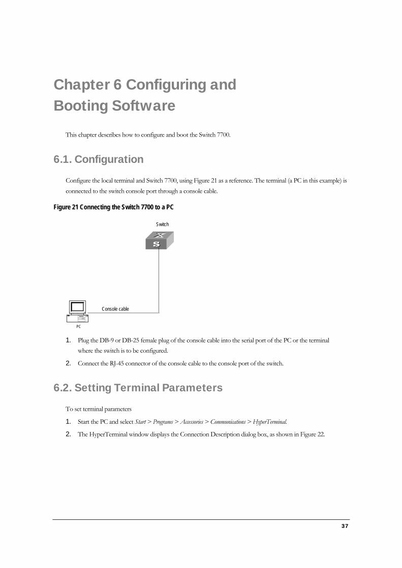
Configure the local terminal and Switch 7700, using Figure 21 as a reference. The terminal (a PC in this example) is connected to the switch console port through a console cable.
Figure 21 Connecting the Switch 7700 to a PC
Console cable
Switch
PC
1. Plug the DB-9 or DB-25 female plug of the console cable into the serial port of the PC or the terminal where the switch is to be configured.
2. Connect the RJ-45 connector of the console cable to the console port of the switch.
6.2. Setting Terminal Parameters
To set terminal parameters
1. Start the PC and select Start > Programs > Accessories > Communications > HyperTerminal.
2. The HyperTerminal window displays the Connection Description dialog box, as shown in Figure 22.
37

C O N F I G U R I N G A N D B O O T I N G S O F T W A R E
Figure 22 Connection Description dialog box
3. Enter the name of the new connection in the Name field and click OK. The dialog box, shown in Figure 23 displays. Select the serial port to be used from the Connect using dropdown menu.
Figure 23 Properties dialog box
4. After selecting serial ports, click OK. The port shown in Figure 24 displays and you can set serial port parameters. Set the following parameters:
Baud rate = 9600
Databit = 8
Parity check = none
Stopbit = 1
38

C O N F I G U R I N G A N D B O O T I N G S O F T W A R E
Flow control = none
Figure 24 COM1 Properties dialog box
5. Click OK. The HyperTerminal dialogue box displays, as shown in Figure 25.
6. Select Properties.
39

C O N F I G U R I N G A N D B O O T I N G S O F T W A R E
Figure 25 HyperTerminal window
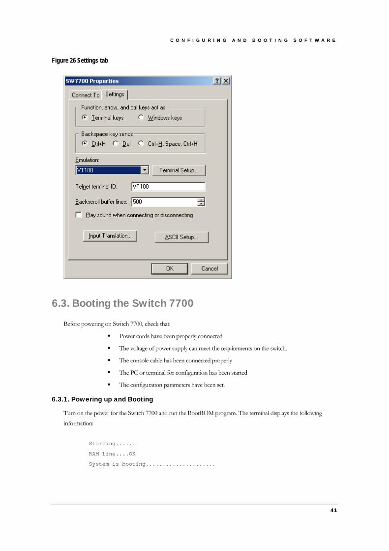
7. In the Properties dialog box, select the Settings tab, as shown in Figure 26.
8. Select VT100 in the Emulation dropdown menu.
9. Click OK.
40
C O N F I G U R I N G A N D B O O T I N G S O F T W A R E
Figure 26 Settings tab
6.3. Booting the Switch 7700
Before powering on Switch 7700, check that:
Power cords have been properly connected
The voltage of power supply can meet the requirements on the switch.
The console cable has been connected properly
The PC or terminal for configuration has been started
The configuration parameters have been set.
6.3.1. Powering up and Booting
Turn on the power for the Switch 7700 and run the BootROM program. The terminal displays the following information:
Starting......
RAM Line....OK
System is booting.....................
41

C O N F I G U R I N G A N D B O O T I N G S O F T W A R E
******************************************
* *
* Switch 7700 BOOTROM, Version 300 *
* *
******************************************
Copyright(C) 2001-2005 by 3Com Corporation, Inc.
Creation date: Mar 25 2003, 09:33:05
CPU type : MPC8260
CPU Clock Speed : 200Mhz
BUS Clock Speed : 66Mhz
Memory Size : 256MB
FAB64 self testing...............................
60X_SDRAM Data lines Selftest.............................OK!
60X_SDRAM Address lines Selftest..........................OK!
60X_SDRAM fast selftest...................................OK!
Please check LEDs.....................LEDs selftest finished!
Switch chip selftest......................................OK!
CPLD selftest.............................................OK!
The switch Mac address is .....................00E0.FC00.7505
Press Ctrl+B to enter Boot Menu... 5
Note: To enter Boot Mode (see Chapter 6), press Ctrl+B during the 5 seconds that “Press Ctrl+B to enter
Boot Menu...5” is displayed. To perform decompression immediately, press ESC while this message is displayed. If you do nothing, the system enters the following auto-booting port within 5 seconds.
Auto-booting....................
Auto booting file is sw7700001.app
There are 2 files in this packet
FAB64 app file <<FAB64001.app>> is...OK
Decompress
Image.....................................................................
..........................................................................
..........................................................................
................................................................OK!
Starting at 0x60000...
User interface Aux0 is available
42

C O N F I G U R I N G A N D B O O T I N G S O F T W A R E
43
The display of these messages indicates the completion of the switch auto-booting. Press Enter and the terminal screen displays:
<3Com>
You can now begin the configuration for the Switch 7700.


Chapter 7 Software Maintenance
7.1. BOOT Menu
After powering on the Switch 7700, run BootROM program. The terminal displays the following information: Starting......
RAM Line....OK
System is booting................
* *
• SW 7700 BOOTROM, Version 1.00 *
* *
Copyright© 2001-2005 by 3Com Corporation.
Creation date : May 26 2002, 10:23:31
CPU type : MPC8260
CPU Clock Speed : 200MHz
BUS Clock Speed : 66MHz
Memory Size : 128MB
SW 7700 main board self testing...............................
60X_SDRAM Data lines Selftest.............................OK!
60X_SDRAM Address lines Selftest..........................OK!
60X_SDRAM fast selftest...................................OK!
LOCAL_SDRAM Data lines Selftest...........................OK!
LOCAL_SDRAM Address lines Selftest........................OK!
LOCAL_SDRAM fast selftest.................................OK!
Please check leds................ .....Led selftest finished!
Switch chip selftest......................................OK!
CPLD selftest.............................................OK!
Press Ctrl-B to enter Boot Menu... 5
Press Ctrl+B. The system displays: Initialize flash file system. Please waiting!
Password :
45

S O F T W A R E M A I N T E N A N C E
Note: To access the BOOT Menu, press Ctrl+B during the 5 seconds that “Press Ctrl-B to enter Boot
Menu...” displays. Within 5 seconds, the system begins program decompression. At this time if you want to access the BOOT Menu, you must reboot the switch.
Enter the BootROM password. After entering the correct password (no password is set for the switch by default), the system will access the BOOT Menu:
Caution: While using the switch, please keep in mind the modified BOOTROM password.
Boot Menu
1: Download application file to flash
2: Select application file to boot
3: Display all files in flash
4: Delete file from flash
5: Modify bootrom password
0: Reboot
Enter your choice(0-5):
7.2. Upgrading Software Using Xmodem
The Xmodem protocol transmits files through serial ports and supports both 128-byte and 1K-byte packets. Xmodem also supports two types of check; normal checksum and CRC. When there is a packet error, retransmission is supported, normally 10 times).
The Xmodem protocol completes transmission by receiving and sending programs. The receiving program first sends the negotiating characters to negotiate the check means. After passing the negotiation, the sending program begins to send the packet. The receiving program checks the packet according to the negotiated means after receiving a complete packet. The acknowledgement characters are sent after passing the check and then the sending program continues to send the next packet. If the check fails, negative characters are sent and the sending program sends the packet again.
1. Enter 1 in the BOOT Menu and press Enter. The system accesses the download application file menu: 1. Set TFTP protocol parameter
2. Set FTP protocol parameter
3. Set XMODEM protocol parameter
0. Return to boot menu
Enter your choice(0-3):3
2. Enter 3 in the download program menu.
3. Select the Xmodem protocol to implement the software upgrade.
4. Press Enter. The system enters the download rate-setting menu: Please select your download baudrate:
1. 9600
46

S O F T W A R E M A I N T E N A N C E
2. 19200
3. 38400
4. 57600
5. 115200
0. Exit
Enter your choice (0-5):5
5. Select the appropriate download speed. For example, enter 5 to select the download speed as 115200bps.
6. Press Enter. The terminal displays the following information: Download baudrate is 115200 bps. Please change the terminal’s baudrate to
115200 bps, and select XMODEM protocol.
Press enter key when ready.
7. Change the baud rate set at the configuration terminal, so that the baud rate is consistent with the selected download baud rate of the software.
8. After the baud rate setting at the configuration terminal is completed, disconnect the terminal and reconnect it.
9. Press Enter to start downloading. The terminal displays the following information: Now please start transfer file with XMODEM protocol.
If you want to exit, Press <Ctrl+X>.
Waiting ... CCCCC
Note: After the terminal baud rate is modified, you must disconnect and then re-connect the terminal
emulator, to effect the new setting.
10. Select [Transfer\Send File] from the terminal window.
11. Click Browse in the Send file dialog box, shown in Figure 27 and select the application you want to download.
12. Change the protocol name for the download to Xmodem.
Figure 27 Send File dialog box
13. Click Send. The dialog box shown in Figure 28 displays.
47
S O F T W A R E M A I N T E N A N C E
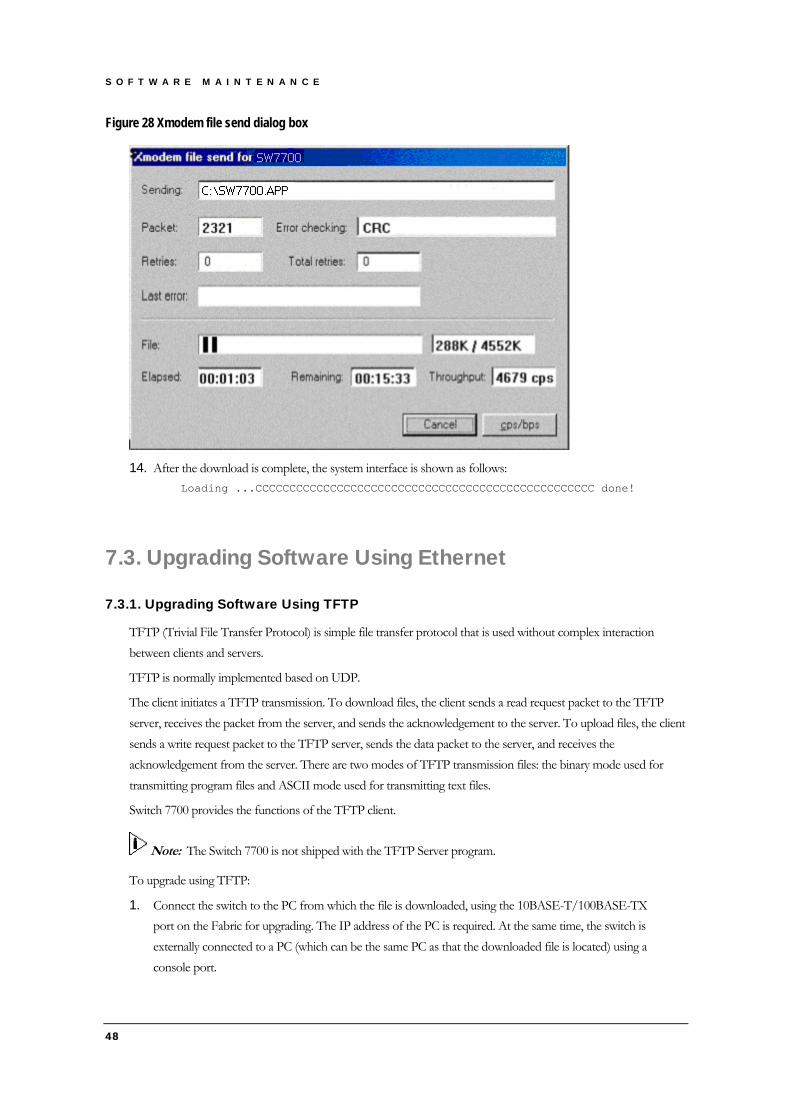
Figure 28 Xmodem file send dialog box
14. After the download is complete, the system interface is shown as follows: Loading ...CCCCCCCCCCCCCCCCCCCCCCCCCCCCCCCCCCCCCCCCCCCCCCCCCC done!
7.3. Upgrading Software Using Ethernet
7.3.1. Upgrading Software Using TFTP
TFTP (Trivial File Transfer Protocol) is simple file transfer protocol that is used without complex interaction between clients and servers.
TFTP is normally implemented based on UDP.
The client initiates a TFTP transmission. To download files, the client sends a read request packet to the TFTP server, receives the packet from the server, and sends the acknowledgement to the server. To upload files, the client sends a write request packet to the TFTP server, sends the data packet to the server, and receives the acknowledgement from the server. There are two modes of TFTP transmission files: the binary mode used for transmitting program files and ASCII mode used for transmitting text files.
Switch 7700 provides the functions of the TFTP client.
Note: The Switch 7700 is not shipped with the TFTP Server program.
To upgrade using TFTP:
1. Connect the switch to the PC from which the file is downloaded, using the 10BASE-T/100BASE-TX port on the Fabric for upgrading. The IP address of the PC is required. At the same time, the switch is externally connected to a PC (which can be the same PC as that the downloaded file is located) using a console port.
48
S O F T W A R E M A I N T E N A N C E
49
2. Run the TFTP Server program on the PC connected with the Ethernet port for upgrading, and specify the file path to the upgrading program.
3. Run the terminal emulator on the PC connected to the console port, and boot the switch to access the BOOT Menu.
4. Enter 1 in the BOOT Menu.
5. Press Enter to access the download application menu as follows. 1. Set TFTP protocol parameter
2. Set FTP protocol parameter
3. Set XMODEM protocol parameter
0. Return to boot menu
Enter your choice(0-3):1
6. Enter 1 in the download application menu to select TFTP.
7. Press Enter The following list of TFTP parameters displays: Load File name:
Switch IP address:
Server IP address:
8. Complete the input of the relevant information based on the actual requirements
9. Press Enter, the system interface is shown as follows: Are you sure to download file to flash? Yes or No(Y/N)
10. Enter Y and the system starts downloading the file. Enter N and the system returns to downloading the program. Enter Y and press Enter, the system begins downloading programs. After the downloading is completed, the system starts write-flash operation. Upon completion of this operation, the terminal display outputs the following information, indicating that the downloading is completed.
Loading ......................................................done!
Writing to flash..............................................done!
7.3.2. Upgrading Software Using FTP
Through the Ethernet port, the Switch 7700 can serve as an FTP server or client. It provides users with another means to download the system program software and configure the files. Take the Switch 7700 serving as an FTP client as an example.
To upgrade with FTP, use the following procedure:
1. Connect the switch to the PC where the upgrade file is loaded, using the Ethernet port 10BASE-T. The IP address of the PC is required. At the same time, the switch is externally connected to a PC (that can be the same one as the one where the downloaded file is located) using the console port.
2. Run the FTP Server program on the PC connected to the Ethernet port for upgrading, and specify the file path to the upgrading program.
3. Run the terminal emulator on the PC connected to the console port, and boot the switch to access the BOOT Menu.

S O F T W A R E M A I N T E N A N C E
50
4. Enter 1 in the BOOT Menu.
5. Press Enter to access the download program menu. 1. Set TFTP protocol parameter
2. Set FTP protocol parameter
3. Set XMODEM protocol parameter
0. Return to boot menu
Enter your choice(0-3):2
6. Enter 2 in the download program menu.
7. Select FTP as the protocol for the software upgrade.
8. Press Enter.
9. Set the FTP protocol parameters: Load File name:
Switch IP address:
Server IP address:
FTP User Name:
FTP User Password:
10. Press Enter. The following question displays: Are you sure to download file to flash? Yes or No(Y/N)
11. If you enter N, the system returns to downloading program menu. If you enter Y, the system downloads the file, performs the write-flash operation, and displays the following information to indicate that the download is complete:
Loading ......................................................done!
Writing to flash..............................................done!
7.4. Lost Passwords
If the BootROM password of the switch is lost, contact your local support center, listed on page 57.

Chapter 8 Hardware Maintenance
Warning: When installing or replacing the power module when the power is on, do not touch any naked
wire, terminal or any part of the product with a dangerous voltage label. Always wear the anti-static wrist strap when replacing the module.
8.1. Replacing a Power Module
To replace a power module, you need:
An anti-static wrist strap
A screwdriver
Use the following steps to replace a power module:
1. Put on the anti-static wrist strap
2. Loosen the captive screw in the module to be replaced, using the screwdriver.
3. Support the module you are removing with one hand and gently pull the handle with the other hand until it slides out of the slot.
4. If you are not going to install another module in this position, install a blank filler plate on the chassis for dust-proofing and heat dissipation.
5. Remove the new power module from the package and check the input mode.
6. Support the module in one hand and hold the handle with another hand. Align the module with the guides in the chassis and slide the module gently into the slot. Ensure the module matches well with the guides.
Caution: As you are inserting the power module, if the pin terminal springs up, the pin cannot be seated into the hole and the system will sound an alarm. If the power module has not been inserted properly, you should slide it out and insert it again to avoid breaking or cracking the power terminals.
7. Fasten the captive screw.
Caution: If the captive screws cannot be fastened, the power module may not have been properly seated. Check them carefully.
The dust-proof cover on the power module can accumulate dust after a long time of usage. To guarantee heat dissipation for the chassis, periodically clean the filter with fresh water and air-dry it.
8.2. Replacing Cards
The FABRIC and I/O modules of the Switch 7700 can be installed and removed basically in the same way. This section describes the general measures of installing and removing these modules.
51

H A R D W A R E M A I N T E N A N C E
To replace a module, you need:
An anti-static wrist strap
Screwdriver
To remove a module:
1. Wear the anti-static wrist strap and remove all the cables from the module to be removed.
2. Loosen the captive screws, using the screwdriver.
3. Hold the ejector levers on the module with both hands, press them toward both sides to separate the connectors of the module from the motherboard.
4. Gently slide the module along the guides out of the slot.
5. Put the removed module into the package.
Note: Replace the blank filler plate on the chassis if you do not install a new module in the place where the old
one was removed.
To replace a module:
1. With both hands, hold the ejector levers on the module that will be installed.
2. Align the module with the guides in the chassis and slide it into the slot gently until you feel the positioning pin on the handle bar touch the hole in the chassis.
3. Press the ejector levers inward and seat the pin on the handle bar into the positioning hole in the chassis.
4. Fasten the captive screws to fix the module, using the screwdriver.
8.3. Replacing the Fan Assembly
As mentioned in Maintenance on page 10, you can hot-swap fan assemblies in the Switch 7700.
Warning: To avoid injury, do not touch any naked wire, terminal, or any part of the product that carries a
dangerous voltage.
To replace a fan assembly:
1. Put on the anti-static wrist strap.
2. With both hands, hold the ejector levers on the fan assembly that will be removed. Press them toward both sides of you to separate the fan assembly connector from the backplane.
3. Slide the fan gently along the guides of the slot and pull it out.
4. With both hands, hold the ejector levers of the fan that will be installed. Press them toward both sides of you. Align it with the guides in the chassis and slide it gently into the slot until you feel the positioning pin on the handle bar touch the hole in the chassis.
5. Press the ejector levers inward and seat the pin on the handle bar into the positioning hole in the chassis.
Warning: Install a new fan soon after removing the old one to ensure that the Switch 7700 works normally.
52
Chapter 9 System Troubleshooting
Although the Switch 7700 has passed comprehensive and strict tests before delivery, faults may occur due to improper installation. This chapter describes how to troubleshoot.
The simplest way to diagnose a fault is to check the system status LEDs on the Fabric modules. In addition, with the DeviceMgr network management system, you can also locate the fault through management software.
9.1. Troubleshooting the Configuration
After the switch is powered on booting information is displayed on the configuration terminal. If the configuration system has failed, there is no screen display at the configuration terminal or the displayed characters are illegible.
9.1.1. No information is displayed on the terminal
After the Switch 7700 is powered on, if there is no information displayed on the terminal, check that:
The power system is working normally.
The Fabric is working normally.
The console cable has been connected to the console port in the Fabric.
If this procedure does not reveal the problem, check that the console cable is properly connected and that the configuration terminal is set correctly.
9.1.2. The displayed characters are illegible
If the displayed characters are illegible, the parameters of configuration terminal may not have been set correctly. Perform the corresponding examinations, referring to Configuration on page 37.
9.2. Troubleshooting Power
If the power LED OK is off, there may be something wrong with the system power supply. Check that:
The power module has been installed in the position to ensure normal communication with the backplane.
The switch power has been turned on.
The power cord has been properly connected.
The source voltage is correct.
Table 30 Power LEDs on the Fabric
Indicator State Description OK On — the power works normally.
53

S Y S T E M T R O U B L E S H O O T I N G
54
Off — the power fails to work or has not been installed yet.
FAIL On — the power fails to work. Off means that the power works normally or has not been installed yet.
9.3. Troubleshooting the Fan
If the fan LED OK is off, check that:
The fan has been installed in the correct position for normal communication with the backplane.
Every heat dissipation fan is working normally.
There is nothing blocking the vent of the chassis.
The blank filler plates are furnished on the chassis where there is no module inserted.
Table 31 Fan LEDs on the Fabric
Indicator State Description
OK On — the fan works normally. Off — the fan fails to work or has not been installed yet.
FAIL On — the fan fails to work. Off — the fan works normally or has not been installed yet.
9.4. Troubleshooting the Cards
The Fabric and I/O module LEDs show the states of the FABRIC and the 6 I/O modules, as described in Table 32.
If the LED ALM of the module remains green or green flashing, it indicates there is something wrong with the module.
During the process of resetting the module, the ALM LED remains on. After normal booting, it is off.
When resetting the module, if the ALM LED remains off, the module may not be connected to the power source. Check that the module has been properly installed in the correct position.
Table 32 Card LEDs on the Fabric
Indicator State Description
RUN Green/Off — the module fails to work or has not been inserted. Green Flashing — the module works normally.
ALM Off — the module works normally or has not been inserted. Remaining on — the module failed to work.

Chapter 10 Technical Support
3Com provides easy access to technical support information through a variety of services. This chapter describes these services.
Information contained in this chapter is correct at time of publication. For the most recent information, 3Com recommends that you access the 3Com Corporation World Wide Web site.
10.1. Online Technical Services
3Com offers worldwide product support 24 hours a day, 7days a week, through the following online systems:
World Wide Web site
3Com Knowledgebase Web Services
3Com FTP site
10.1.1. World Wide Web Site
To access the latest networking information on the 3Com Corporation World Wide Web site, enter this URL into your Internet browser:
http://www.3com.com/
This service provides access to online support information such as technical documentation and software library, as well as support options that range from technical education to maintenance and professional services.
10.1.2. 3Com Knowledgebase Web Services
The 3Com Knowledgebase is a database of technical information to help you install, upgrade, configure, or support 3Com products. The Knowledgebase is updated daily with technical information discovered by 3Com technical support engineers. This complimentary service, which is available 24 hours a day, 7 days a week to 3Com customers and partners, is located on the 3Com Corporation World Wide Web site at:
http://www.knowledgebase_3com.com/
10.1.3. 3Com FTP Site
Download drivers, patches, software, and MIBs across the Internet from the 3Com public FTP site. This service is available 24 hours a day, 7 days a week.
To connect to the 3Com FTP site, enter the following information into your FTP client:
Hostname: ftp.3com.com
Username: anonymous
Password: <your Internet e-mail address>
Note: You do not need a user name and password with Web browser software such as Netscape Navigator
and Internet Explorer.
55

T E C H N I C A L S U P P O R T
10.2. Support from Your Network Supplier
If you require additional assistance, contact your network supplier. Many suppliers are authorized 3Com service partners who are qualified to provide a variety of services, including network planning, installation, hardware maintenance, application training, and support services.
When you contact your network supplier for assistance, have the following information ready:
Product model name, part number, and serial number
A list of system hardware and software, including revision levels
Diagnostic error messages
Details about recent configuration changes, if applicable
If you are unable to contact your network supplier, see the following section on how to contact 3Com.
10.3. Support from 3Com
If you are unable to obtain assistance from the 3Com online technical resources or from your network supplier, 3Com offers email and telephone technical support services. To find out more about your support options, email or call the 3Com technical support services at the location nearest you.
10.3.1. Email Support
Some 3Com regions offer an email support service. To access this service for your region, use the appropriate URL or email address from the list below.
Asia, Pacific Rim
From this region, email: [email protected]
Europe, Middle East and Africa
Enter the URL: http://emea.3com.com/support/email.html
Latin America
Spanish speakers, enter the URL: http://lat.3com.com/lat/support/form.html
Portuguese speakers, enter the URL: http://lat.3com.com/br/support/form.html
English speakers, email: [email protected]
10.3.2. Telephone Support
When you contact 3Com for assistance, have the following information ready:
Product model name, part number, and serial number
A list of system hardware and software, including revision levels
Diagnostic error messages
Details about recent configuration changes, if applicable
Table 33 provides a list of worldwide technical telephone support numbers. These numbers are correct at the time of publication. Refer to the 3Com Web site for updated information.
56
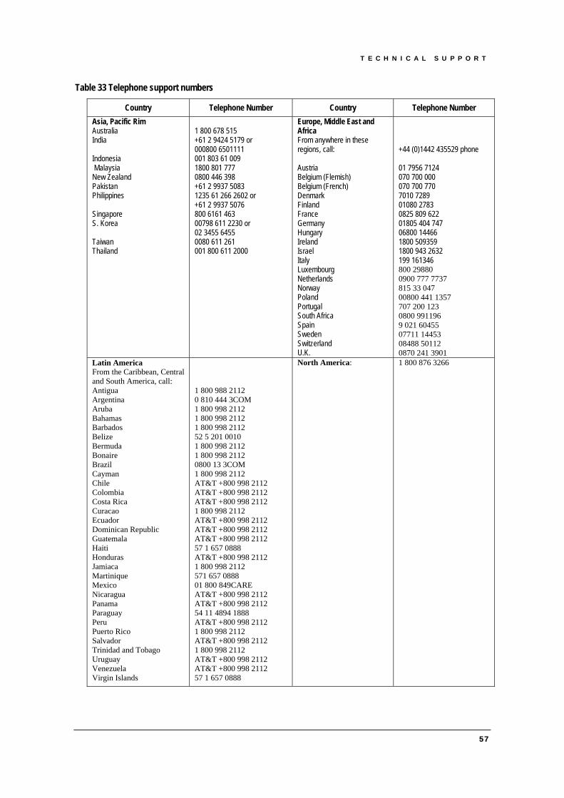
T E C H N I C A L S U P P O R T
Table 33 Telephone support numbers
Country Telephone Number Country Telephone Number Asia, Pacific Rim Australia India Indonesia Malaysia New Zealand Pakistan Philippines Singapore S. Korea Taiwan Thailand
1 800 678 515 +61 2 9424 5179 or 000800 6501111 001 803 61 009 1800 801 777 0800 446 398 +61 2 9937 5083 1235 61 266 2602 or +61 2 9937 5076 800 6161 463 00798 611 2230 or 02 3455 6455 0080 611 261 001 800 611 2000
Europe, Middle East and Africa From anywhere in these regions, call: Austria Belgium (Flemish) Belgium (French) Denmark Finland France Germany Hungary Ireland Israel Italy Luxembourg Netherlands Norway Poland Portugal South Africa Spain Sweden Switzerland U.K.
+44 (0)1442 435529 phone 01 7956 7124 070 700 000 070 700 770 7010 7289 01080 2783 0825 809 622 01805 404 747 06800 14466 1800 509359 1800 943 2632 199 161346 800 29880 0900 777 7737 815 33 047 00800 441 1357 707 200 123 0800 991196 9 021 60455 07711 14453 08488 50112 0870 241 3901
Latin America From the Caribbean, Central and South America, call: Antigua Argentina Aruba Bahamas Barbados Belize Bermuda Bonaire Brazil Cayman Chile Colombia Costa Rica Curacao Ecuador Dominican Republic Guatemala Haiti Honduras Jamiaca Martinique Mexico Nicaragua Panama Paraguay Peru Puerto Rico Salvador Trinidad and Tobago Uruguay Venezuela Virgin Islands
1 800 988 2112 0 810 444 3COM 1 800 998 2112 1 800 998 2112 1 800 998 2112 52 5 201 0010 1 800 998 2112 1 800 998 2112 0800 13 3COM 1 800 998 2112 AT&T +800 998 2112 AT&T +800 998 2112 AT&T +800 998 2112 1 800 998 2112 AT&T +800 998 2112 AT&T +800 998 2112 AT&T +800 998 2112 57 1 657 0888 AT&T +800 998 2112 1 800 998 2112 571 657 0888 01 800 849CARE AT&T +800 998 2112 AT&T +800 998 2112 54 11 4894 1888 AT&T +800 998 2112 1 800 998 2112 AT&T +800 998 2112 1 800 998 2112 AT&T +800 998 2112 AT&T +800 998 2112 57 1 657 0888
North America: 1 800 876 3266
57

T E C H N I C A L S U P P O R T
10.4. Returning Products for Repair
Before you send a product directly to 3Com for repair, you must first obtain an authorization number. Products sent to 3Com without authorization numbers will be returned to the sender unopened, at the sender’s expense.
You can obtain an authorization number (called an RMA) by entering the following URL into your Internet browser:
http://www.3com.com/support/en_US/repair
Alternatively, you can obtain an RMA by calling or faxing one of the numbers in Table 34:
Table 34 Fax Numbers for return authorization numbers
Country Telephone Number Fax Number Asia, Pacific Rim +65 543 6500 +65 543 6348 Europe, Middle East and Africa Austria Belgium (Flemish) Belgium (French) Denmark Finland France Germany Hungary Ireland Israel Italy Luxembourg Netherlands Norway Poland Portugal South Africa Spain Sweden Switzerland U.K.
+44 (0)1442 435529 01 7956 7124 070 700 000 070 700 770 7010 7289 01080 2783 0825 809 622 01805 404 747 06800 14466 1800 509359 1800 943 2632 199 161346 800 29880 0900 777 7737 815 33 047 00800 441 1357 707 200 123 0800 991196 9 021 60455 07711 14453 08488 50112 0870 241 3901
USA and Canada 1 800 876 3266 1 508 323 6061 (not toll free) Latin America Antigua Argentina Aruba Bahamas Barbados Belize Bermuda Bonaire Brazil Cayman Chile Colombia Costa Rica Curacao Ecuador Dominican Republic Guatemala Haiti Honduras Jamiaca Martinique Mexico
1-800-988-2112 0-810-444-3COM 1-800-998-2112 1-800-998-2112 1-800-998-2112 52-5-201-0010 1-800-998-2112 1-800-998-2112 0800-13-3COM 1-800-998-2112 AT&T +800-998-2112 AT&T +800-998-2112 AT&T +800-998-2112 1-800-998-2112 AT&T +800-998-2112 AT&T +800-998-2112 AT&T +800-998-2112 57-1-657-0888 AT&T +800-998-2112 1-800-998-2112 57-1-657-0888 01-800-849CARE
58

T E C H N I C A L S U P P O R T
Nicaragua Panama Paraguay Peru Puerto Rico Salvador Trinidad and Tobago Uruguay Venezuela Virgin Islands
AT&T +800-998-2112 AT&T +800-998-2112 54-11-4894-1888 AT&T +800-998-2112 1-800-998-2112 AT&T +800-998-2112 1-800-998-2112 AT&T +800-998-2112 AT&T +800-998-2112 57-1-657-0888
59