swimming pools design 2011 rev3.pdf
TRANSCRIPT

8/14/2019 Swimming Pools Design 2011 Rev3.pdf
http://slidepdf.com/reader/full/swimming-pools-design-2011-rev3pdf 1/97
February Revision 003 © Sport England 2011
DesignGuidance Note
Updated & Combined guidance
Creating sporting opportunities in every community
SwimmingPoolsUpdated Guidance for 2011
8/14/2019 Swimming Pools Design 2011 Rev3.pdf
http://slidepdf.com/reader/full/swimming-pools-design-2011-rev3pdf 2/97
Swimming Pools Design
Guidance Note
February Revision 003 1 © Sport England 2011
Foreword
Sport England believes that good facilities arefundamental to developing sporting opportunitiesfor everyone, from the youngest beginner to theinternational class athlete. The buildings, whetherlarge or small, can encourage civic pride and assistthe process of revitalising deprived neighbourhoods.Facilities that are well designed, built to last andwell maintained are a pleasure to use and give anample return on the time and money invested intheir construction and day to day use.
Good design needs to be based on a soundunderstanding of issues such as the current trendsand practices within individual sports, developments
in the sport and leisure industry and the lessons tobe learnt from previously built schemes.
Good design needs to be embraced within theearliest vision statement for a particular projectand enshrined in the initial briefing stage throughto the final detailed specifications and operationalarrangements.
Sport England Design Guidance notes aim topromote a greater general understanding of overalldesign concepts, an appreciation of technicalissues as well as the critical factors that need tobe considered in reaching the appropriate solutionfor a particular project. They also advise where
further information, advice and expertise may befound and point to benchmark examples.
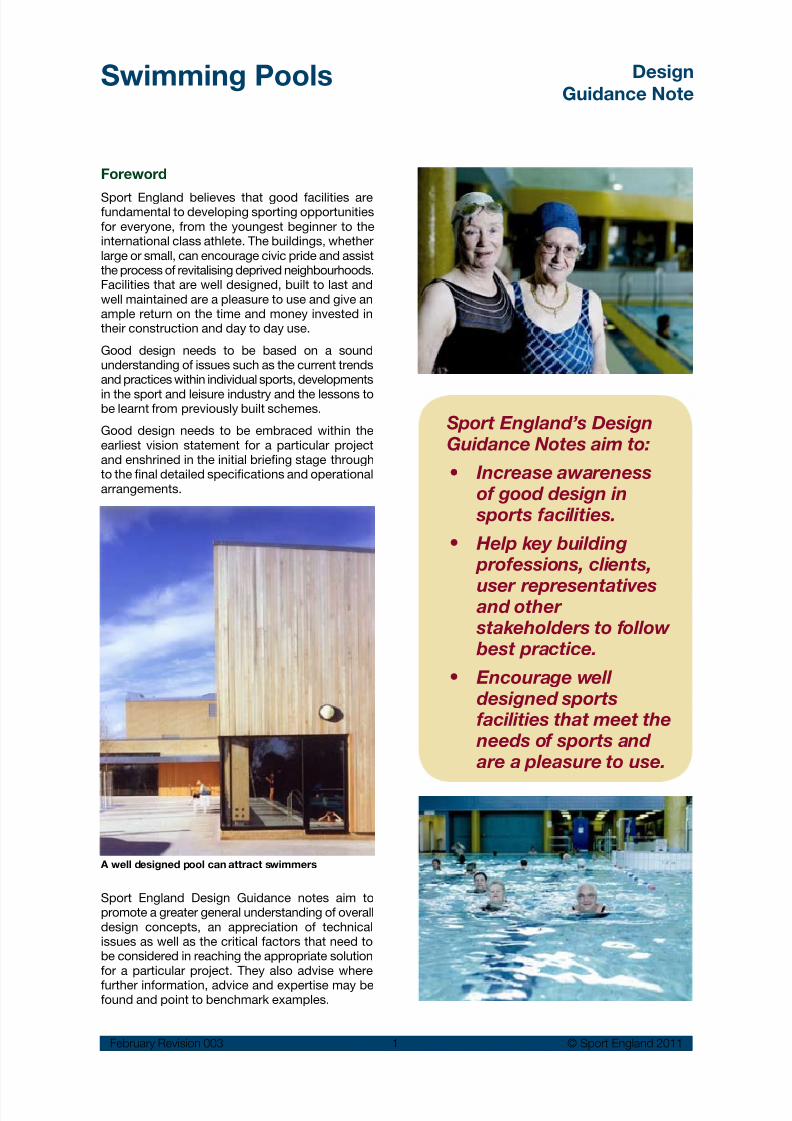
A well designed pool can attract swimmers
Increase awarenessof good design in
sports facilities.
Help key building professions, clients,
user representatives and other stakeholders to follow best practice.
Encourage welldesigned sportsfacilities that meet the
needs of sports and are a pleasure to use.
•
•
•
Sport England’s DesignGuidance Notes aim to:

8/14/2019 Swimming Pools Design 2011 Rev3.pdf
http://slidepdf.com/reader/full/swimming-pools-design-2011-rev3pdf 3/97
Swimming Pools Design
Guidance Note
February Revision 003 2 © Sport England 2011
Contents1.0 Introduction 3
National statistics•
Trends•
Condition and public expectation•
Partnership and cooperation•
2.0 Early considerations 5
Financial sustainability•
Strategic issues•
Size and shape of water•
Level of competition•
Pool capacity•
Leisure features•
3.0 Site 12
Location and site evaluation•
Site planning•
External design•
4.0 Organising the building 16
4.1 Relationship of spaces 16
4.2 First impressions 19
Entrance area•
Reception desk•
Refreshment areas•
Public toilets• Accommodation for children•
4.3 Pool hall 23
Structural approach•
Glazing•
Artificial lighting•
Signs•
4.4 Pool tank(s) 26
Configuration•
Main pool•
Combining two pools in one hall•
Learner and training pools•
Diving pools•Easy access to the water•
Privacy for some user groups•
Movable floors and bulkheads•
4.5 Changing facilities 41
Key design issues•
General planning principles•
Changing layouts•
Analysis of types of changing rooms•
Calculating numbers•
Benches, coat hooks and lockers•
Toilets•
Showers• Vanity areas•
4.6 Ancillary accommodation 49
Office accommodation•
Staff rooms and changing•Cleaners store•
External service yard•
First aid room•
Pool equipment store•
4.7 Typical fixtures and fittings 52
4.8 Spectator & competitor provision 55
5.0 Servicing the building 57
Energy implications•
Energy efficiency•
Renewable energy•
Water efficiency•Pool water quality•
Disinfection•
Chemical dosing•
Water softness•
Filtration systems•
Turnover rates•
Water temperature•
Air temperature and humidity•
Electrical installations•
Size of plant room•
Plant room spaces•
Air distribution systems•
6.0 Constructing the building 65
Types of pool tank design and surround•
Pool edge details•
Finishes to wet areas•
Structural frame•
Roof enclosure•
External walls•
Glazing•
Internal walls•
Movable floors and bulkheads•
Fixed pool equipment•
Stainless steel in the pool hall environment•Doors and frames•
Acoustics•
7.0 Operating the building 79
Key operational / design issues•
Key maintenance issues•
8.0 Appendices 81
Related organisations 811.
Standards and legislation 822.
Changing room calculations example 853.
Improvement and alterations to existing4.
swimming pools 87
Further information on leisure pools 935.
Further information and references6. 95

8/14/2019 Swimming Pools Design 2011 Rev3.pdf
http://slidepdf.com/reader/full/swimming-pools-design-2011-rev3pdf 4/97
Swimming Pools Design
Guidance Note
February Revision 003 3 © Sport England 2011
1.0 Introduction
This guidance note outlines the basic principlesand concepts of good swimming pool design. It isaimed at all those involved in developing swimmingprovision, points to further information and givesa number of best practice examples.
Swimming is second only to walking as the nation’smost popular physical activity with over 22% of
adults and 50% of young people taking part on aregular basis 1. It can be enjoyed by people of bothsexes and by all ages and abilities and isrecognised as being uniquely beneficial to thenation’s health and well being. It is ideally suitedfor people with disabilities and the elderly or infirmwho might have difficulties with other forms ofexercise.
Swimming and water safety is an essential life skill. As part of the National Curriculum, it canencourage fitness and good health practicesamongst young people. It is regarded as anessential part of children’s education of the safe
enjoyment of most water activities and anunderstanding of the wider environment aroundthem.
Swimming, like all other sports, can play asignificant part in community regeneration andnew or refurbished pools can provide much valuedfacilities that make an important contribution tocommunity cohesion and general health and wellbeing.
National statisticsIt is estimated 2 that there are almost 1,400swimming clubs and associations in Englandranging from small clubs which concentrate on theteaching of swimming to the very large clubsinvolved in competition in swimming, diving,synchronised swimming, water polo, open waterand disabled swimming. These voluntaryorganisations provide the foundations forcompetitions at all levels and the development oftalent. Swimming pools also provide for a widerange of other activities from aqua-aerobics tosub-aqua training, and most commonly simple
recreational and fitness swimming.It is also estimated 3 that there are almost 4,614separate swimming pools sites in England with atotal water 872,910m2. Approximately 25% of thiswater area is provided by the education sector,46% by local authorities (or trusts) and 26% by thecommercial sector. The stock of pools is in variousforms:
Indoor or outdoors•
Free form or rectangular•
Heated or unheated•
Associated with hotels, health clubs, water•parks, beaches and other private operations.
Trends
In recent years England has seen a growth ofcommercial pools to the point that in numericalterms they are now almost equal to the numbersof Local Authority pools. However the commercialpools tend to be small in size and with shallowerwater, being aimed primarily at the fitness / aerobic / recreation market. They tend to offer a reduced
1 Sport England Active People Survey.
2 ASA ‘From Arm Bands to Gold Medals’ 2001/2.3 State of the Nation Facility Report – Swimming Pools –November 2007.
Swimming can be enjoyed by people of both sexes across all ages and abilities and is recognised as being uniquely beneficial to the nation’s health and well being.

8/14/2019 Swimming Pools Design 2011 Rev3.pdf
http://slidepdf.com/reader/full/swimming-pools-design-2011-rev3pdf 5/97
Swimming Pools Design
Guidance Note
February Revision 003 4 © Sport England 2011
programme of activities and have restrictivepricing. They are less likely to allow for competitionswimming or teaching. The trend for the educationsector is to be a diminishing provider of swimmingfacilities.
Condition and public expectation
It has been acknowledged by Government thatpublic swimming facilities in England havegenerally suffered from under funding and needconstant maintenance and repair, placing manyunder threat of closure 4.
Only a few of the Victorian municipal baths, oncethe pride of Britain’s big cities, remain. In addition,
hundreds of council pools built in the 1960s and1970s are close to the end of their economic lifespan. Local Authorities are often faced with thedifficult decisions to close pools with strong localopposition. In some cases these are buildings ofhistorical and architectural importance 5.
There are also considerable pressures on schoolswhere the majority of pools were built in the 60’sand early 70’s, many to a poor standard. Schoolsface logistical problems, additional costs, health &safety issues and time and staff training issues indelivering the national curriculum. TheGovernment’s ‘Building Schools for the Future
programme’, to rebuild or refurbish all secondaryschools over a 15 year period may result in manyexisting pools not being refurbished or replaced 6.
Best practice includes:
New community pools•
that cater for school needs
Existing public and•
commercial pools being shared between schools and the widercommunity.
4 DCMS Spending review 2004.
5 Great Lengths: The historic indoor swimming pools of
Britain. English Heritage.6 Building Schools for the Future: Adding value withswimming. ASA.
7 Programmes of swimming activities are also drawn upwithin the National Curriculum for Key Stages 1, 3 and 4.
In contrast, the last decade saw a growing numberof lottery funded swimming pools. Modern design,together with more attractive internal features andgreater attention to customer’s needs has createda step change in pool provision. The Active Placesdatabase shows that since 1996 some 56% of thenational stock has been built or benefited fromsome degree of refurbishment. However, thelikelihood of significant lottery funding beingavailable in the immediate future is doubtful.
Partnership and cooperation
Careful consideration needs to be given to theoverall justification and briefing for swimmingprovision.
Schools, Local Education Authorities, healthagencies and local government should seek towork with members of the wider community tocapitalise on knowledge, experience andresources. They should seek to establish clearswimming strategies.
Existing pool provision in any particular area mayneed to be rationalised; schools with existing poolsmight share them with other schools and the widercommunity; pools being refurbished or replacedshould consider the needs of the entirecommunity.
The ‘Swimming Charter 2003’ published byDepartment of Children, Schools & Families (DCSF)and the Department of Culture, Media and Sport(DCMS) gives various case studies whereswimming has been provided on a communitybasis to allow school swimming to move beyondthe essential minimum requirement of Key Stage2 of the National Curriculum 7.
There is also an impressive core of organisationsconcerned with development, management andsafety issues. See Appendix 1.

8/14/2019 Swimming Pools Design 2011 Rev3.pdf
http://slidepdf.com/reader/full/swimming-pools-design-2011-rev3pdf 6/97
Swimming Pools Design
Guidance Note
February Revision 003 5 © Sport England 2011
Good design can: Maximise customer appeal •
Allow flexibility for•
maximum programmeoptions
Provide efficient and well•
organised circulation
Minimise staffing levels•
whilst allowing theeffective management of health and safety
Help achieve sustainability•
and be responsive toenvironmental issues
Minimise cleaning and•
maintenance requirements
Reduce the footprint and•
volume Help achieve financial•
sustainability.
2.0 Early Considerations
Public swimming pools are unusually demandingbuildings that require considerable investment todesign, build and operate. Much of the plant mustoperate continuously 24 hours a day over 365 daysa year under stringent health and safetyrequirements to ensure safe, supervised use. Theyhave high energy needs in operation and must becarefully designed to conserve energy. Theycontain aggressive chemicals in moisture-ladenatmospheres that require careful design and highquality materials, plant and equipment and wellqualified staff.
The full environmental impact of such buildings
through their life cycle should be carefullyconsidered and it is recommended that theBREEAM assessment method be adopted 8.
Pools outside the public sector, though possiblyless intensively used, must also achieve safe andacceptable operating conditions.
All new pools will need to be designed in line with thenew European standard BSEN 15288-1:2008. See Appendix 2. Existing Health & Safety documentationwill also need to be carefully considered in respect ofboth design and operation of a pool 9.
The Construction (Design and Management)
Regulations 2007 (CDM 2007) which, in conjunctionwith the Heath and Safety at Work Act and BSEN15288-1:2008, identifies the need to establish astrong project team. This team should includedesigners, client, operators and contractors withsound experience and expertise with similarprojects in both scale and type from the outset ofany project. Refer also to the Sport England / CABEdocument ‘Better Places for Sport’ available fromthe Sport England website.
8 The Building Research Establishment Environmental Assessment Method (BREEAM) includes leisure buildings.http://www.breeam.org/page.jsp?id=14
9 Health & Safety Executive’s (HSE) document HSG179Managing Health & Safety in Swimming Pools’ , PAS 39,PAS 65 and PWTAG Guide.

8/14/2019 Swimming Pools Design 2011 Rev3.pdf
http://slidepdf.com/reader/full/swimming-pools-design-2011-rev3pdf 7/97
Swimming Pools Design
Guidance Note
February Revision 003 6 © Sport England 2011
Establish a strong projectteam including client,designers, operator andcontractors with soundexperience and expertisefrom the outset.
Financial sustainability
Even the best designed public pools are likely tobe run on a subsidised basis and it is important toconsider the long term financial sustainability fromthe outset. The initial capital costs and the ongoingoperational costs should be balanced with thebenefits that will be offered.
There are strong arguments for swimming pools tobe combined with other facilities such as healthand fitness facilities. This way they produce anincome stream without incurring excessiveadditional running costs in order to offset subsidiesand to achieve economies of scale. It is essentialthat realistic business planning runs in tandem with
the planning and design processes.
Leisure features
A number of pools include some leisure water areathat includes features designed to increase appealand attract custom. There are ranges of possibleoptions that may include:
Varying water depths, with extensive shallow•or beach areas
Wave pools and surfing pools•
Water slides & flumes•
Fast flowing river rides & rapids•
Water jets & water cannons•
Water features e.g. rain showers•Spa facilities, including varying temperatures•
Children’s wet play equipment•
Feature lighting and sound – to introduce a•more theatrical environment
Theming to increase excitement and appeal.•
Larger scale leisure centres are usually planned as‘destination’ facilities that attract people from awide catchment for a ‘day out’ experience.
Leisure features are outside the scope of this
guidance note, but further information is includedin Appendix 5.
Strategic Issues
The following strategic questions need to beconsidered:
The fit with the local authority’s leisure/ •recreation strategy and sports developmentinitiatives?
Sporting objectives: for example the impact•on local community participation or the
significance on a wider catchment of specialisttraining and competition features?
Cost pyramid: Value for money is essential - Invest ingood design and specification to reduce whole life costs(staff, maintenance, repair and running cost)-Ensureadequate maintenance budgets are available.
Design team fees
Construction costs
Heating, lighting
cleaning and
maintenance
Staff
Capital
costs
Revenue
costs

8/14/2019 Swimming Pools Design 2011 Rev3.pdf
http://slidepdf.com/reader/full/swimming-pools-design-2011-rev3pdf 8/97
Swimming Pools Design
Guidance Note
February Revision 003 7 © Sport England 2011
The user profile of the catchment area: who•will use it and when?
Whether the need can be met elsewhere or by•other means, for example by upgrading orextending an existing pool?
The impact on existing facilities• 10?
It is crucial that client groups liaise with their•local authority, their regional Sport Englandoffice, and advisory bodies such as the Amateur Swimming Association (ASA) todetermine:
Whether there is a local strategy forO
swimming pool provision that covers the
area?
What is the best size and type of facilityO
recommended for their particularlocation?
On the Sport England website there is a sectionaimed at those involved in the development ofsport in their local community and sustainablecommunity strategy. This is a new tool that replacesthe 1999 Sport England publication ‘Planning Across Boundaries’.
A swimming development strategy is essential to setout the context of sporting
and managementobjectives for any new
provision.
Ensure that balanceddecisions are made about
need and financial
resources.
Key questions
Who will be the principal users?•
What activities need to be accommodated?•
Type, size and depth of pool(s) required?•
Number of people who will use the pool at any•one time?
Will the pool be used for competitive•swimming? – (What activities and to whatstandard?)
Is spectator viewing required and what level•can be justified?
Pool users will comprise a combination of thefollowing groups:
Local community including ethnic / cultural•groups
Schools•
Swimming clubs•
People with disabilities•
Older people•
Carers with babies and young children.•
The main types of activity are likely to be:
Recreational swimming•
Learning to swim, including water-•acclimatisation for young children
Fitness swimming: e.g. lane swimming and•aqua aerobics
Training•
Competitive swimming.•
Other activities may include:
Diving•
Water polo•
Synchronised swimming•
Canoe practice•
Life saving practice•
Sub-aqua training•
Underwater hockey•Leisure activities•
Private parties.•
Nearly all of these activities can be accommodatedin a standard 25m (or 20m11 ) community pool withdepths ranging from 0.9m–1.8m, by simply dividingthe area with floating lane markers. For example,teaching swimming and shallow dives, recreationaland fitness swimming, aqua aerobics, life savingpractice and sub-aqua training.
10 The Sport England Active People website hassegmentation data available from late 2007.
11 More suitable for school sites or remote rural locations.

8/14/2019 Swimming Pools Design 2011 Rev3.pdf
http://slidepdf.com/reader/full/swimming-pools-design-2011-rev3pdf 9/97
Swimming Pools Design
Guidance Note
February Revision 003 8 © Sport England 2011
It should be recognisedthat new, replacement or
refurbished pools, which meet present day standards, have the effectof increasing use. If the proposed pool water
area is too small it will beunder constant pressureduring busy periods.
Conversely pools that areoversized may be underused, less cost-effective
and likely to result in greater financial deficit.S
Wet Change
Plant room
RZ AST
PT
FA
SwimmingPool
Refreshment and viewing area
LearnerPool
Key:
AST: Attendant staff accommodation
FA: First Aid
PT: Public toilets
R: Reception
RZ: Refreshement Zone e.g. vending, kitchen
S: Store
R
Diagrammatic layout of a 4-lane 25m community poolwith minimum circulation and good visibility of all keyfeatures incorporating viewing area.
Size and shape of water
Many small pools will be used solely for recreationaland fitness swimming and will not necessarily needto strictly follow the ASA recommendations.However, it is generally recommended that standarddimensions should be used to allow appropriatelevels of competition and training and to help meetsafety standards. On the other hand relatively fewpools need be designed to full competition
standards and include spectator facilities 12.
Single community pools should have a minimumshallow water depth of 0.9m (if there is no learnerpool) and a deep end of 1.8m or 2.0m. Where alearner pool is provided the shallow water depthof the main pool should be increased to 1.0m inorder to better cope with tumble turns.
12 Further advice on spectator seating is given on page 55. 13 Also referred to as booms.
Training for competition, low level synchronisedswimming, and water polo can all take place in a25m pool and with modest spectator seating thepool will also be able to accommodate competitive
events in these activities.
Diving from boards, advanced synchronisedswimming and more advanced sub-aqua trainingrequire deeper water. These can all beaccommodated in one pool tank, which ideally should be in addition to the main swimming pool. A dedicated tank for deep-water use may be anessential requirement for some activities at certainlevels of competition.
The provision of separate water areas for differentactivities is, however, unlikely to be a cost-effectivesolution and difficult to justify, except where
competition is a specific requirement. A moreeconomical approach is to include a movablefloor(s) and bulkhead(s) 13 to divide a single pooltank and create separate pool water areas ofdifferent depths. This allows greater use andprogramming flexibility. There are many ways suchfeatures can be configured and these are discussedin more detail from page 39.
Early advice should be sought from a range ofmanufacturers/suppliers on the overall designimplications of integrating their plant / equipmentinto a design and a cost comparison carried out todetermine the most appropriate option.

8/14/2019 Swimming Pools Design 2011 Rev3.pdf
http://slidepdf.com/reader/full/swimming-pools-design-2011-rev3pdf 10/97
Swimming Pools Design
Guidance Note
February Revision 003 9 © Sport England 2011
Levels of competition
A new pool should be designed to meet the variousneeds of all the community it serves and in mostinstances designing for community use will allowthe pool to be used by one or more of the 1,400clubs which are a member of the AmateurSwimming Association (ASA). Where the pool is tobe used for higher levels of competition it may benecessary to consider the specific needs of the ASA and for major competitions the requirements
of the Federation Internationale de Natation Amateur (FINA)14. However these requirementsdo not prevent use by the general community.
Building elements affected include:
Dimensions and tolerances of the pool tank(s)•and pool surrounds
Sectional profile and water depths•
Provision of ancillary water areas – e.g. learner•pool that can double as a swim down pool
Poolside equipment including timing and•score board
Diving facilities•
Spectator seating•
Support accommodation•
Standards of illumination and water•treatment.
Consultation should occur early in the designprocess with the ASA and FINA as appropriate.FINA facility rules are available from theirwebsite.
ASA National Hierarchy 15
The ASA National Hierarchy identifies where aswimming facility may sit in respect of nationalswimming development as follows:
Swimming
50m major competition pools•
50m (or 25m) national/regional competition•pools
50m (or 25m) national intensive training•centres *
25m 8-lane county competition pools•
25m 6 lane community pools•
20m 4 lane small community or school pool•
Teaching/learner pools.•
Diving
High performance centres *•
World-class training centres *•
County and sub regional development centres.*•
Water Polo
International* sized playing areas•
County and sub regional development centres•25 x 12.5m deep water.
Synchronised swimming
International competition pools•
County and sub regional development centres•minimum 2.5 m depth.
* It should be noted that terms such as high performance,world class, international, national and regional, often refermore to the coaches and standard of athletes in developmentprogrammes run in particular facilities.
14 International Amateur Swimming Federation.15 Source: ‘From Armbands to Gold Medals’ - The NationalFacilities Strategy for Swimming.

8/14/2019 Swimming Pools Design 2011 Rev3.pdf
http://slidepdf.com/reader/full/swimming-pools-design-2011-rev3pdf 11/97
Swimming Pools Design
Guidance Note
February Revision 003 10 © Sport England 2011
20m
8 . 5 m
1 7 m
8 . 5 m
1 0 . 5 m
1 3 m
25m
4 lane
8 lane
4 lane
5 lane
6 lane
10 - 20m
7 m
2 5 m
8 lanes
50m
side margin (or additional lane)
side margin (or additional lane)
50m Max competition pool + **
50m training pool - Width varies depending on need.
25m County Standard pool + **
25m recommended communityswimming pool +**
25m 5 lane communityswimming pool **
25m 4 lane communityswimming pool **
20m 4 lane community pool **
7 x 10 - 20m learner pool **
Pool Type Length(m)
Width
(m)
No ofLanes
Lane
Width
Side Margin(m)
Depth(m)
Learner Pool ** 10 - 20 7 2 2.0 N/A 0.6 – 0.9
* Lengths given for competition include an
allowance for timing pads.
** Provision of a movable floor allows the pool to be
put to multi-purpose community use.
+ Spectator & competitior seating provision should
be discussed with the ASA/FINA appropriate to
level of competition.
Minimum width of 10m - 4 lanes x 2.5m or 5 lanes x 2m. **
Community 20m ** 20 8.5
10.5
4
5
2.0 0.25 0.8 – 1.0
Community 25m ** 25 8.510.512.5
456
2.0 0.25 0.9 – 1.5 min 1.0 - 2.0 pref
Competition + 25.02* 13 6 2.0 0.5 1.0 - 1.80 min Short Course Championship + 25.02* 17 8 2.0 0.5 1.80
Training Pool 50 10 - 17 4 - 8 2.0 0.5 1.0 - 1.80 min ASA National Competition + 50.02* 19
218 2.25 §
2.50.5 1.0 - 1.80 min
2.0 pref
FINA National Competition + 50.02* 21 8 2.5 0.2min0.5pref
1.35min2.0 pref
§ Standard timing pad widths are 1.9m (2m lanes) or 2.4m (2.5m lanes). 2.25m wide lanes require bespoke timing panels.
50.02* 25 8 2.5 2.5 2.0 minFINA International Competition +
For water depths of 0.8m or less, changes in pool
depths should be achieved with gradients of 1 in 20
(5%). For water depths between 0.8m and 1.35m,
changes in pool depths should be achieved withgradients no steeper than 1 in 17 (6%). Where pool
depths continue down to 1.5 or 1.8m the same gradient
should preferably be continued. See diagram for tank
profiles, depths and gradients on page 32.
Table 1 Main pools - layouts and dimensions
8/14/2019 Swimming Pools Design 2011 Rev3.pdf
http://slidepdf.com/reader/full/swimming-pools-design-2011-rev3pdf 12/97
Swimming Pools Design
Guidance Note
February Revision 003 11 © Sport England 2011
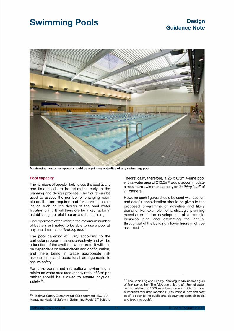
Pool capacity
The numbers of people likely to use the pool at anyone time needs to be estimated early in theplanning and design process. The figure can beused to assess the number of changing roomplaces that are required and for more technicalissues such as the design of the pool waterfiltration plant. It will therefore be a key factor inestablishing the total floor area of the building.
Pool operators often refer to the maximum numberof bathers estimated to be able to use a pool atany one time as the ‘bathing load’.
The pool capacity will vary according to theparticular programme session/activity and will bea function of the available water area. It will alsobe dependent on water depth and configuration,and there being in place appropriate riskassessments and operational arrangements toensure safety.
For un-programmed recreational swimming aminimum water area (occupancy ratio) of 3m2 perbather should be allowed to ensure physicalsafety
16.
16 Health & Safety Executive’s (HSE) document HSG179Managing Health & Safety in Swimming Pools’ 3rd Edition.
17 The Sport England Facility Planning Model uses a figureof 6m2 per bather. The ASA use a figure of 13m2 of waterper population of 1000 as a bench mark guide to Local
Authorities for urban locations. (Assuming a ’pay and playpool’ is open to the public and discounting open air poolsand teaching pools).
Theoretically, therefore, a 25 x 8.5m 4-lane poolwith a water area of 212.5m2 would accommodatea maximum swimmer capacity or ‘bathing load’ of71 bathers.
However such figures should be used with cautionand careful consideration should be given to theproposed programme of activities and likelydemand. For example, for a strategic planningexercise or in the development of a realisticbusiness plan and estimating the annualthroughput of the building a lower figure might beassumed
17.
Maximising customer appeal should be a primary objective of any swimming pool

8/14/2019 Swimming Pools Design 2011 Rev3.pdf
http://slidepdf.com/reader/full/swimming-pools-design-2011-rev3pdf 13/97
Swimming Pools Design
Guidance Note
February Revision 003 12 © Sport England 2011
3.0 Site
Location and site evaluationBefore finally selecting a site it is essential that itis fully evaluated in terms of catchment, potentialmarket and user demographics, as mentionedunder ‘Strategic Issues’.
A technical analysis should also assess:
Space for the proposed facility and for future•expansion
Site constraints such as shape and contours•and whether they can be used to reduceexcavation or the visual impact of the proposedbuilding
The bearing capacity of the ground, soil•condition and depth of the water table,particularly in relation to the pool tank andneighbouring buildings that may be linked toor be close to the pool building
Accessibility for pedestrians, cyclists, cars,•coaches, service and emergency vehicles andpublic transport
Potential car parking for users and staff•
Location of existing public services, especially•the capacity for waste water drainage
Links with existing recreational/sports and•educational facilities in order to benefit fromshared management and grouped facilities.
Site planning
Once a site has been selected the position of thepool will depend on a range of factors:
Position of existing and new access roads and•public utility services
Orientation in relation to natural lighting and•solar glare
Visibility of the facility and how it complements•its surroundings
Car parking, including potential for overflow•parking
Access for service and emergency vehicles•
Soil sub-strata conditions and depth of the•water table from the soil survey.
External design
Swimming pools cater for all sections of society:parents with children, schools, the elderly, ethnicgroups and people with disabilities amongstothers. The external design must reflect the
specific needs of these groups in the same way asthe interior of the building.
It is recommended that reference is made to SportEngland’s ‘Car Park and Landscape Design’ designguidance note and ‘Active Design’ downloadavailable from the Sport England website.
Principal points for consideration include:
The main entrance should be clearly visible•from the main pedestrian and vehicularapproaches to the site. Where this is difficult
or impossible to achieve such as in tight urbansites, existing schools or on college sites, forexample, there should be clear signs givingdirections to the main entrance and related carparking areas.
Direct and well-defined hard landscaped•route(s) should be provided for pedestriansfrom the site boundary to the main entrance.These routes should be separated from carsand cycles, although they will be linked toparking areas.
Safe route(s) should be planned to avoid•
circulation problems such as road crossings(particularly on education sites).
Seating areas along pedestrian routes (over•50m).
Drop off point as close as possible to the•entrance.
Access for people with disabilities, including•wheelchair users, must be provided.Incorporate dedicated car parking close to theentrance.
Service and maintenance access should be•separate from public car parking and the mainentrance. This may include the provision of a
A facility should compliment its surroundings.

8/14/2019 Swimming Pools Design 2011 Rev3.pdf
http://slidepdf.com/reader/full/swimming-pools-design-2011-rev3pdf 14/97
Swimming Pools Design
Guidance Note
February Revision 003 13 © Sport England 2011
screened service yard for the delivery of goodsand refuse collection 18.
Access to a first aid room with a dedicated•space for emergency vehicle parking andadequately sized doors for stretcher access.
Security for users with well lit public parking,•appropriate landscaping and pedestrian routeslocated away from areas of potentialconcealment.
Coach parking spaces and/or turning space,•particularly if the facility serves children fromlocal schools or if it is a ‘destination’ venue fora wider catchment.
Secure and separate bicycle parking with•racks located under cover close to the mainentrance and, preferably, visible from the office / reception.
Carefully considered evergreen planting and/ •or trees to prevent unacceptable levels of glarein the pool hall.
The following factors have an impact on theexternal appearance of pool buildings:
Swimming pools are generally large volume•spaces. The massing, scale and volume of the
building will be key planning considerations,especially in relation to its location and context.
Activities such as diving, where high diving•boards are provided could substantiallyincrease the overall height of the building andits scale.
Water slides or flumes (if included) can be used asan external feature to express their ‘fun’ elementand provide a further visual attraction. They shouldform an integral part of the overall design and,ideally, be visible from the main approach to thebuilding.
The choice of an appropriate structural•approach and material for the large spanscovering the pool hall and ancillaryaccommodation.
It is essential that the glazing design is carefully•
considered to avoid glare and specularreflection inside the pool hall 19.
The aim is to provide the optimum balance of•natural lighting that avoids gloomy conditionsin the pool hall.
Windows allowing views in and out of the pool•hall need careful consideration and should beconsidered in relation to the need for privacy.
Windows can provide dramatic effects both•internally and externally, particularly at night.
A well positioned and landscaped pool building
18 Delivery of pool treatment chemicals will require carefulconsideration – see the Pool Water Treatment Advisory Group(PWTAG) publication ‘Swimming Pool Water – Treatment andQuality Standards’ and the Health & Safety Executive’s (HSE)document HSG179 ‘Managing Health & Safety in SwimmingPools’ 3rd Edition – IRSM Industry Guidance.
19 See section 4.3 on glazing and the safety implications ofglare and direct sun penetration into the building andmethods of mitigation.

8/14/2019 Swimming Pools Design 2011 Rev3.pdf
http://slidepdf.com/reader/full/swimming-pools-design-2011-rev3pdf 15/97
Swimming Pools Design
Guidance Note
February Revision 003 14 © Sport England 2011
Set down point
Clear direct pedestrian footpathswith clearly defined cross-overpoints where vehicle andpedestrian routes intersect
Separatestaff parkingincluding disabled
parking provision
Outdoor sun bathing areas, whenprovided, should be positioned so thatthey have sunlight throughout the day
Orientation of the pool hall may be
critical depending upon planning,site constraints and the need
for controlled natural lighting
throughout the day minimising
the risk of specular glare
Consider need forspace for additionalcar parking provisionfor 'specialist events'
or for future expansionof centre
Screenedservice yard
Potential futureexpansion
Separate access
for plant, chemicaldelivery and first aid
Access for emergency
vehicle parking
Main entrance givenvisual emphasis andprotection by canopy
Well lit car parkwith simple
vehicle circulation C o a c h p a r k i n g
Seat
road
of main entrance
Exit for use atpeak times
Main
Bus stop
Bus stop
Office has views
Bicycles V i e w s o u t f r o m p
o o l h a l l
approach andbicycle parking
Assistance dog
rest area Seat
Low planting allowing
Pedestraincrossing
car parking to beclearly visible
boundary
Main entrance visiblefrom main road/ site
Prominently positionedsign indicating name ofcentre, facilitiesprovided and other
information
Notional site layout indicating desirable features (not to scale)

8/14/2019 Swimming Pools Design 2011 Rev3.pdf
http://slidepdf.com/reader/full/swimming-pools-design-2011-rev3pdf 16/97
Swimming Pools Design
Guidance Note
February Revision 003 15 © Sport England 2011
Clear signage raises the profile of a building. Where possible signage should be incorporated into the overall designrather than be applied separately
An example of successful location, massing and use of materials for a small community pool

8/14/2019 Swimming Pools Design 2011 Rev3.pdf
http://slidepdf.com/reader/full/swimming-pools-design-2011-rev3pdf 17/97
Swimming Pools Design
Guidance Note
February Revision 003 16 © Sport England 2011
4.0 Organising the building
This section considers the main elements of a swimming pool building.
4.1 Relationship of spaces
Vehicular
access
Pool hall
FA
Cl
Admin.Entrance
foyer
Staff
facilities
S
PT
Plant
room
Serviceyard
Public
parking
Staff
parking
Viewing
Social &refreshment
area
Pool
changing
R
T
Coach
parking
Key:
S: Store
Cl: Cleaner's store
FA: First Aid
P: Pre/post swim showers
T: Toilets
R: Reception
PT: Public toilets
Vehicular
access
Pool hall Sports
hall
FA SCl
PT
Admin.
Entrance
foyer
Staff
facilities
Dry
changing
SCl
PT
Plant
room
Service
yard
Public
parkingStaff
parking
Viewing
Social &
refreshment
area
Pool
changing
R
Future expansion
T
Relationship between main areas of a typical pool building
Relationship between main areas of a wet and dry sports centre
8/14/2019 Swimming Pools Design 2011 Rev3.pdf
http://slidepdf.com/reader/full/swimming-pools-design-2011-rev3pdf 18/97
Swimming Pools Design
Guidance Note
February Revision 003 17 © Sport England 2011
S
Sports hall
PT
'Dry' change
Pool hall
Adminoffices
Refreshment& viewing area
Futureextension
R
AST
FA
Future
extension
S
'Wet' change
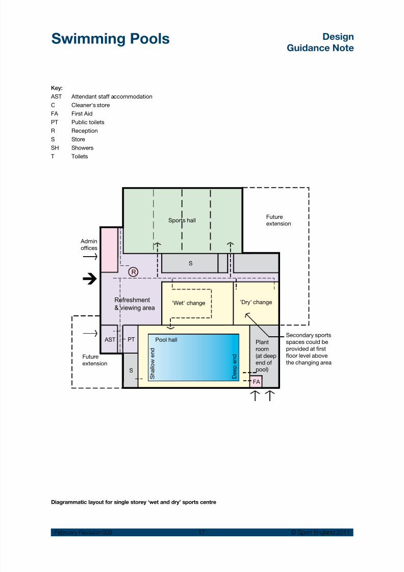
Secondary sports
spaces could be
provided at first
floor level above
the changing area
Plant
room
(at deep
end ofpool)
S h a l l o w e
n d
D e e p e n d
Key:
AST
C
FA
PT
R
S
SH
T
Attendant staff accommodation
Cleaner's store
First Aid
Public toilets
Reception
Store
Showers
Toilets
Diagrammatic layout for single storey ‘wet and dry’ sports centre

8/14/2019 Swimming Pools Design 2011 Rev3.pdf
http://slidepdf.com/reader/full/swimming-pools-design-2011-rev3pdf 19/97
Swimming Pools Design
Guidance Note
February Revision 003 18 © Sport England 2011
Diagrammatic layouts for a two storey swimming pool building
Plant
room
S
Fitness
equipment room
Space over pool hall
Admin.
offices
Exercise
studio
'Dry'
changing
& toilets
Plant
room
C S
Wet change
Pool hall
PT
Refreshment
& viewing
area
Future
extension
R
AST
Key:
AST
C
FA
PT
R
S
SH
T
Attendant staff accommodation
Cleaner's store
First Aid
Public toilets
Reception
Store
Showers
Toilets
Spectator seating
FA

8/14/2019 Swimming Pools Design 2011 Rev3.pdf
http://slidepdf.com/reader/full/swimming-pools-design-2011-rev3pdf 20/97
Swimming Pools Design
Guidance Note
February Revision 003 19 © Sport England 2011
4.2 First impressions
Swimming pool buildings should be attractive andwell maintained to ensure lasting customer appeal.The customer experience starts with the approachto the building. The position of the building on thesite and the quality of the surrounding landscapingare important elements. Scale and identity are alsoimportant design factors in both rural and urbanenvironments.
Signage and lighting can also assist greatly inpromoting the building and may be used toreinforce its external identity.
The entrance should have sufficient space tocreate clear orientation for customers and beinviting and non-threatening. It should also alloweffective and unobtrusive supervision by staff. Apositive first impression will influence visitors’perceptions of the facility as a whole. The materialsand colours will also influence the overall image ofthe reception area and can provide a theme for therest of the building.
Open arrangements work well with good levels oftransparency into the main areas of the building,such as the pool hall, refreshment areas and anyassociated fitness facilities. However, appropriatesecurity measures will be required to avoidunauthorised access. In addition, an effectiveenvironmental separation should be maintainedwith pool/wet areas that have high temperature,humidity and air-borne chemicals.
A dedicated welcome area may be provided inlarger centres enabling staff to provide newcustomers with key information on the servicesavailable.
The need to create a
good first impression begins at the entrance.
A positive first impression will influence visitors’ perceptions of thefacility as a whole.
A well proportioned entrance with clear and direct
access from the roadside
Entrance area
The entrance area should provide sufficient spacefor groups of people to circulate, view notices orwait for friends. At peak times the sudden influx ofcustomers may require managed space forqueuing.
An open and uncluttered reception area easescirculation and customer orientation. The entrancearea should include:
Clear and easily accessed ‘in’ and ‘out’•
circulation routes A draught lobby to reduce heat loss provided•with suitable dirt removing surface andautomatic doors designed for easy access forall
A prominently positioned and instantly•identifiable reception desk
A clearly signed and direct circulation route•from the main entrance to the changing roomsvia the reception desk
Key information should be provided using•clear signage to explain, for example, if
changing rooms are separate ‘male andfemale’ or ‘shared’.
In addition:
Automatic doors need to be carefully positioned•as they can cause draughts when both sets ofdoors are open at the same time
Notice boards and signs are required to•indicate opening times and promote activitiesand services available to users
A public telephone accessible to all users.•

8/14/2019 Swimming Pools Design 2011 Rev3.pdf
http://slidepdf.com/reader/full/swimming-pools-design-2011-rev3pdf 21/97
Swimming Pools Design
Guidance Note
February Revision 003 20 © Sport England 2011
Reception desk
Location and layout
The reception desk is of prime importance and itslocation, appearance and lighting will impact onthe whole area. There are two main types:
Island:• Its central location occupies morespace but can suit larger centres with both wetand dry facilities, where separate circulationand space for queuing are required. Thearrangement can be confusing to newcustomers and more difficult to control. It’sisolation from offices and stores can complicateoperation.
Sidewall:• located to one side of the entrancearea and usually linked directly to an office/ store. This option is more suitable for smallercentres allowing the counter to be unmannedduring quiet periods leaving office staff to dealwith the occasional customer.
The reception desk should be located to allow:
Visual supervision of the entrance/exits routes•and all adjoining areas.
Restriction of unsupervised access by•arranging the circulation pattern to pass thereception desk.
Where security is a high priority security•barriers/screens should be integrated into thedesign and be in close proximity to thereception. In some cases a position for asecurity guard may be required. Mobile oradjustable barriers might also be used at peaktimes.
Suitable artificial lighting for reception staff at•all times of day.
Direct access to other parts of the building•including the pool hall, social and changingareas.
Adequate queuing space between the point of•entry and the desk based on estimatednumbers of users.
Cross-circulation in front of the reception desk orthrough queuing areas should be avoided.
Vending
Publictoilets
Seating /
viewing area
Reception
Offices
Viewingarea
Glazedscreen
Poolhall
Notice
boardS
T
Officesoverlook
forecourt
Views of social
area from mainapproach
Turnstile / gate
ADW
WBS
WBS Wheelchair / buggy storage area
Key
ADW Assistance dog waiting area.
T Public telephone at low level
S Store
Entrance and foyer arrangement for a typical small pool building with upper floor accommodation

8/14/2019 Swimming Pools Design 2011 Rev3.pdf
http://slidepdf.com/reader/full/swimming-pools-design-2011-rev3pdf 22/97
Swimming Pools Design
Guidance Note
February Revision 003 21 © Sport England 2011
Cash handling
The design of the reception area should takeaccount of issues associated with handling cash. A secure area will be required for cashing up at theend of the day and possible overnight cashstorage. In larger facilities, a pneumatic cashhandling system may be included between remotecash points and the cash storage area.
Ventilation
Adequate ventilation should be provided to createcomfortable working conditions, particularly whenrooflights are sited above the reception desk.
Access Control
The initial design should anticipate the need foraccess control appropriate to the scale and natureof the facility. A system may include the provisionof gates, turnstiles or barriers and allowanceshould be made for suitable access and egress forwheelchairs and pushchairs.
The access system may also incorporate acombination of control systems based upon:
Magnetic swipe/smart card or PIN code•through a membership control system.
Pay as you Go system using paper tickets,•
magnetic swipe tickets and/or tokens eitherpre-purchased or obtained from reception.
Manually controlled access by reception staff•or a security guard.
‘Accessible Sports Facilities’ design guidance noteavailable from the Sport England website givesdetails of space requirements and otherrequirements.
Large café/reception area overlooking pool area
Refreshment areas
A refreshment area is often located close to the
main entrance with views of the pool hall. They areusually intended for those who use the pool orother activity areas, but may also be located beforethe reception desk in order to attract passing trade.However, in smaller centres it may not be possibleto justify more than a few vending machines inassociation with some informal viewing areas.
The social/refreshment area should be positionedon a primary route so that it will attract visitors’attention as they enter and leave the facility. Iflocating the refreshment area on an upper level isunavoidable, it should be linked by prominentstairs to the foyer and be clearly visible from the
foyer area.The size and scale of refreshment provision willdepend on:
Signage begins atthe entrance and
should display:
Opening times and•
emergency numbers
Clear directions to•
help circulation and
orientation Remember that manyusers, in addition to
partially sighted people, remove their glasses and contact lenses to swim.
Signage should be largewith contrasting colours
and be easily read.See page 26 for signage
required on the pool surrounds.

8/14/2019 Swimming Pools Design 2011 Rev3.pdf
http://slidepdf.com/reader/full/swimming-pools-design-2011-rev3pdf 23/97
Swimming Pools Design
Guidance Note
February Revision 003 22 © Sport England 2011
The number of people expected to use the•building and whether the pool is linked to, oris part of, a larger centre containing dry activityareas?
Whether the pool is part of a community centre•with a bar and kitchen?
The location of the pool building and whether•the neighbouring area already has adequaterefreshment facilities?
The type of menu to be offered?•
Opportunities for brand sponsorship?•
Consider the following points in the design/layout
for all pool refreshment areas:
Regardless of the scale of the facility, allow•space for at least two or three vendingmachines positioned in a wall recess to reducebulk and integrate within the overall design ofthe area. They should also be positioned toavoid repetitive/cross-circulation problemsand allow space for people to stand in front ofthe machine. Avoid positioning machines closeto door swings.
Select easily cleaned, impervious floor finishes•in areas subjected to heavy trafficking, soilingand likely spillage in order to meet hygieneregulations and minimise the risk ofaccidents.
Ensure that lockable storage space for vending•machine products is close by.
Provide seating and table space appropriate•to the size of facility, with good views of thepool hall and located adjacent to publictoilets.
Ensure that catering facilities meet with the•requirements of the Food Safety (General FoodHygiene) Regulations 1995, including any
provision for staff sanitary accommodation.Refreshment areas can be planned as integralparts of the pool hall, or separated from it by aglazed screen. This will stop spectators distractingchildren during swimming lessons and avoidhumidity and smells making the spaceuncomfortable. It will also stop drinks and foodgetting on to the pool side.
A barrier may, however, be sufficient, if the poolenvironment is well controlled and designed toprovide comfortable conditions for spectators 20.
A small community pool will require sufficientspace in the refreshment area for up to 20people.
Snack bar: advice on design and layout should•be sought from a catering specialist. It is likelyto include a seating area, counter and servery,food preparation area/kitchen, food storagearea(s) and waste disposal facility.
Licensed bar: legal advice must be sought and•great care taken to meet the appropriate
licensing requirements, particularly if thecentre is run by a charity. It may need to bephysically separated from other areas. Mostbreweries will give advice on the layout/designof the bar, including storage, if they haveagreement to act as supplier.
Public toilets
Ideally toilet facilities should include male andfemale accessible toilets for users with disabilities. At least one unisex accessible toilet should alsobe provided.
For small community pools with a limited social/ viewing area, a unisex WC compartment shouldbe provided, accessible to disabled users, inaddition to any accessible provision within thechanging areas. For larger facilities, the provisionof accessible toilets should be considered inrespect of an overall access strategy. Refer toregulations and standards 21.
The social/refreshment area should be positioned so that itwill attract visitors’
attention as they enter and leave the facility.
20 See Section 4.8.
21 BS8300:2001 Design of buildings and their approachesto meet the needs of disabled people.
Building Regulations - Approved Document Part M 2004 andthe ‘Accessible Sports Facilities’ design guidance note availablefrom the Sport England website.
For some programme sessions, it may benecessary to close blinds or curtains to createprivacy in the pool.

8/14/2019 Swimming Pools Design 2011 Rev3.pdf
http://slidepdf.com/reader/full/swimming-pools-design-2011-rev3pdf 24/97
Swimming Pools Design
Guidance Note
February Revision 003 23 © Sport England 2011
Cafe area can be passively supervised from reception andoffers views to the pool and the building surroundings
Accommodation for children
Pushchair and pram storage: a baby buggystorage with security locks should be located closeto the entrance preferably in sight of the receptionarea. In addition there should be sufficient spacein the changing rooms for carers who prefer to usethe buggies whilst changing themselves or theirchildren.
Baby change facilities: Baby changing facilitiesshould be easily accessible. They should be wellventilated and equipped with an adjustablechanging shelf, a large purpose made nappydisposal bin and an adjacent washbasin. Provisioncan be within the male and female toilets and/orby providing one or more unisex accessible roomswith enough space for a parent, 2 children and apush chair (See BS 6465 and BS 8300). This maybe integrated into a unisex accessible changingroom with toilet or by providing a dedicated unisexaccessible parent and child toilet.
Childcare facilities: Accommodation for crèchesor playgroups should be located at ground leveland have direct access to a secure fire exit. Thebest facilities are linked to the outside with a secureand protected courtyard providing outdoor playfacilities.
Levels of provision vary significantly depending onwhether crèche, playgroup, nursery or day-carefacilities are required and the length of stay.
A licensed childcare facility will need to complywith current Ofsted National Standards 22.
4.3 Pool hall
Structural approach
The sectional profile and height of the pool halland adjoining areas such as changing areas,may impact upon the scale of the spaces makingthem feel either: light and spacious; orclaustrophobic and oppressive. There are anumber of structural roof options that may beconsidered:
Simple pitched roofs•
Curved roofs with the high point centered over•the pool width
Sloping or curved mono-pitch•
Staggered or ‘saw tooth’ roofs•
Flat roofs.•
Each option has advantages and disadvantagesrelated to the specific site, internal volume andenvironmental requirements.
The internal height of the pool hall may vary•
Where the ceiling or roof is flat, for a 25 x 8.5m•(4 lane) pool a minimum clear height of 3.5mshould be considered
For a profiled ceiling or roof, the minimum•height for a similarly sized pool, should bebetween 4.5 and 6.0m at the highest point,dropping to 3.5m at the lowest point.
The volume of the swimming pool hall will have aninfluence on the acoustic environment and theextent of acoustic absorption material that isrequired to limit the reverberation time to anacceptable level. See page 75 for more details.
It helps backstroke swimmers if there are exposedstructural elements or rooflights running parallel tothe length of the pool, to provide a visual
reference.
Glazing
Natural lighting can give life and sparkle to thepool hall interior, but it needs to be carefullycontrolled and considered with the generalorientation of the building. Roof glazing over thelength of the pool hall can provide good naturallight allowing sunlight to be reflected off internalside walls whilst keeping glare, solar gain andheat loss to acceptable levels.
22 Refer to Ofsted publication ‘Crèches: Guidance to theNational Standards’ published by DfES: Standard 4 –Physical Environment. Similar publications are available forother levels of childcare.
8/14/2019 Swimming Pools Design 2011 Rev3.pdf
http://slidepdf.com/reader/full/swimming-pools-design-2011-rev3pdf 25/97
Swimming Pools Design
Guidance Note
February Revision 003 24 © Sport England 2011
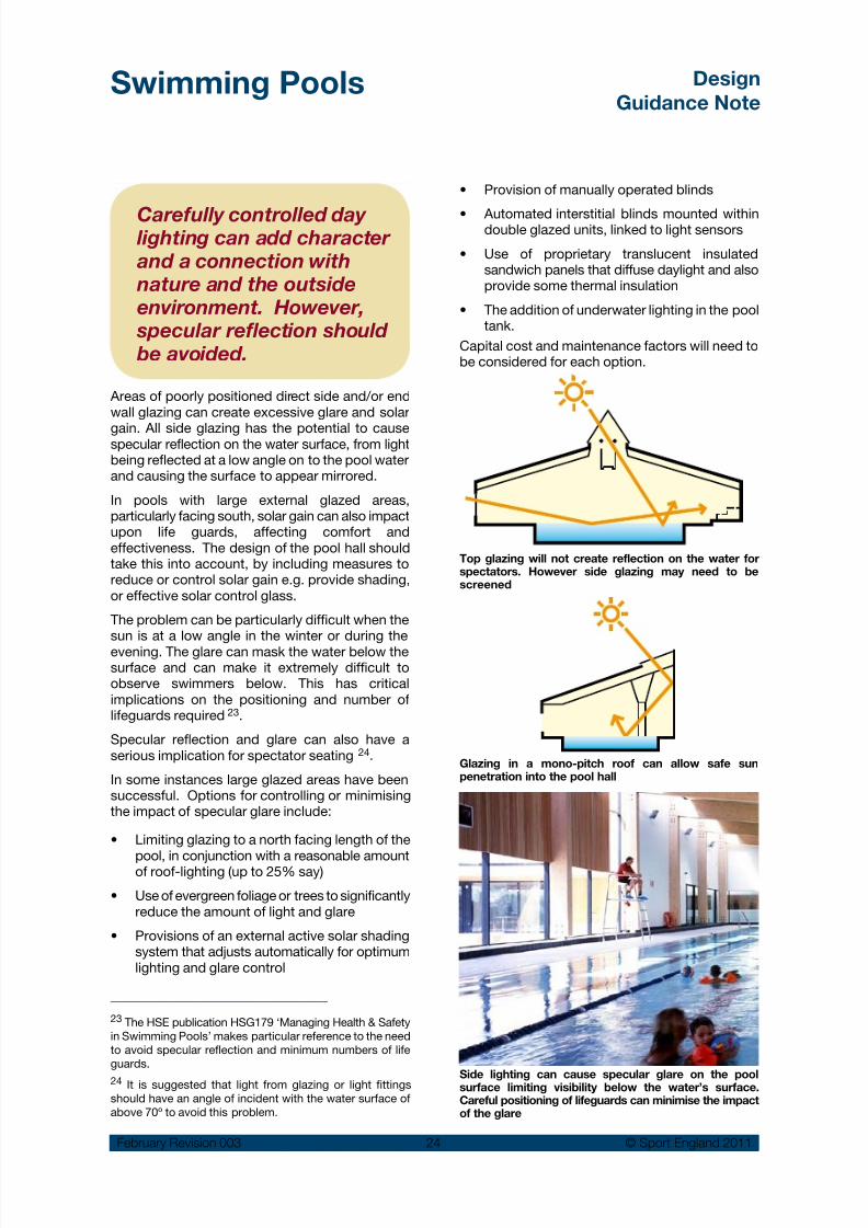
Carefully controlled day lighting can add character and a connection with nature and the outsideenvironment. However,
specular reflection should be avoided.
Areas of poorly positioned direct side and/or endwall glazing can create excessive glare and solar
gain. All side glazing has the potential to causespecular reflection on the water surface, from lightbeing reflected at a low angle on to the pool waterand causing the surface to appear mirrored.
In pools with large external glazed areas,particularly facing south, solar gain can also impactupon life guards, affecting comfort andeffectiveness. The design of the pool hall shouldtake this into account, by including measures toreduce or control solar gain e.g. provide shading,or effective solar control glass.
The problem can be particularly difficult when thesun is at a low angle in the winter or during theevening. The glare can mask the water below thesurface and can make it extremely difficult toobserve swimmers below. This has criticalimplications on the positioning and number oflifeguards required 23.
Specular reflection and glare can also have aserious implication for spectator seating 24.
In some instances large glazed areas have beensuccessful. Options for controlling or minimisingthe impact of specular glare include:
Limiting glazing to a north facing length of the•
pool, in conjunction with a reasonable amountof roof-lighting (up to 25% say)
Use of evergreen foliage or trees to significantly•reduce the amount of light and glare
Provisions of an external active solar shading•system that adjusts automatically for optimumlighting and glare control
Provision of manually operated blinds•
Automated interstitial blinds mounted within•double glazed units, linked to light sensors
Use of proprietary translucent insulated•sandwich panels that diffuse daylight and alsoprovide some thermal insulation
The addition of underwater lighting in the pool•tank.
Capital cost and maintenance factors will need tobe considered for each option.
23 The HSE publication HSG179 ‘Managing Health & Safetyin Swimming Pools’ makes particular reference to the needto avoid specular reflection and minimum numbers of lifeguards.
24 It is suggested that light from glazing or light fittingsshould have an angle of incident with the water surface ofabove 70º to avoid this problem.
Top glazing will not create reflection on the water forspectators. However side glazing may need to bescreened
Glazing in a mono-pitch roof can allow safe sunpenetration into the pool hall
Side lighting can cause specular glare on the poolsurface limiting visibility below the water’s surface.Careful positioning of lifeguards can minimise the impactof the glare

8/14/2019 Swimming Pools Design 2011 Rev3.pdf
http://slidepdf.com/reader/full/swimming-pools-design-2011-rev3pdf 26/97
Swimming Pools Design
Guidance Note
February Revision 003 25 © Sport England 2011
Community pool hall with an exposed roof structuretop-lighting and low level windows
Artificial lighting
Artificial lighting and colour schemes will impactupon the general ambience of the space, and canaffect the colour of bathers’ flesh tones and theappearance of the water.
Light fittings should be located above poolsurrounds for ease of access or alternativelyaccess from a gantry if over the pool water. Lightfittings should be directed so they cause minimalglare or reflection to bathers in the water and staffon the pool surrounds. Up-lighting rather thandirect lighting is preferred for general illuminationas this allows a more even distribution of light, andobviates glare.
Fittings should generally be of the discharge typeas the lower wattage type fittings are unlikely tomeet the lighting needs. The type of dischargefitting should be selected on illumination
performance, colour rendering, lamp life andenergy efficiency. It is important that the fittingsdo not cause significant spectral change to thecolour of finishes with the pool hall.
Providing reliable and evenly spread artificialunderwater lighting can be difficult to achieve.Underwater areas left in shadow can be detrimentalto the ability to see objects clearly in the pool. Although there are currently no regulations relatingto underwater lighting, CIE* 62: 1984 TechnicalReport: ‘Lighting for Swimming Pools’ providesguidance. However compliance with this reportcan result in high capital and running costs,particularly for high end installations.
Underwater lighting therefore requires carefulspecialist design. This will need to take intoaccount:
The building design characteristics, type of•
pool, competition standards etc (to determinethe level of illumination required).
The characteristics of the proposed fittings•(e.g. direct or indirect fittings),
The light output, angle of light distribution and•number of fittings required.
A well designed underwater artificial lightingsystem can provide several benefits:
Improve the appearance of the pool and pool•hall – particularly at night
Improve visibility below water level•Improve safety within the pool• 25.
Up lighter accessible from pool side. Or alternatively forlarger pools an overhead gantry. Underwater lighting shouldbe selected based on speed and ease of re-lamping.
The use of light colours, particularly on walls andceiling surfaces close tothe pool tank, willcontribute to a warm and‘sunny’ atmosphere.
Artificial Lighting:
300 lux* for most activities
500 lux* for competition
International events require higher levels:
FINA: 600 lux at the turn and start ends
Olympics: 1500 lux overthe entire pool**.* Refer to CIBSE Lighting Guide 4: Sports
Lighting
** Television requirements that will rarely be used
in most 50m pools
25 CIE – International Commission of Lighting

8/14/2019 Swimming Pools Design 2011 Rev3.pdf
http://slidepdf.com/reader/full/swimming-pools-design-2011-rev3pdf 27/97

8/14/2019 Swimming Pools Design 2011 Rev3.pdf
http://slidepdf.com/reader/full/swimming-pools-design-2011-rev3pdf 28/97
Swimming Pools Design
Guidance Note
February Revision 003 27 © Sport England 2011
Table 2 Pool surround widths preferred by the AmateurSwimming Association (ASA)
Table 3 Minimum requirements for widths of poolsurrounds from BS EN 15288: Part 1: 2008 (See diagram)
Main Pool Start End Turn End Sides
20m
Community2m 2m 1.5m
25m
Community3m 2m 2m
25m
Competition4m 3m 2–3m
50m
International7m 5m 4-6m
Learner Pool Access Side
2m
Other Side
1.5-2m
Diving Pool Board End
Opposite
End Sides
Generally 4–6m 2–4m 3–4m
International 6–7m 3–5m 4–6m
Dim
ref
Location Clearance
(minimum)
A Entrance wall to pool 3.0m
B Pool to wall at exit points(ladders / steps)
2.5m
C Pool to wall in areas of
diving boards / platforms
3.0m
D Diving pool to wall 4.5m
E Minimum circulation spacearound installations / features
1.25m
F1 Distance between a diving /swimmers pool and a nonswimmers pool area, in theabsence of separation
4.0m
F2 Main pool to diving pool inthe absence of separation
3.0m
G1 Pool to wall for pools under300m2
1.25m
G2 Pool to wall for pools over300m2 1.5m
Notes:
Subject to overall pool design, the ASA’s preferred1 .general dimensions for the pool surrounds may need tobe increased to meet the minimum requirements forcertain prescribed areas around the pool as set out inBS EN 15288 Part 1 2008. See Table 3 below.
For international, world or Olympic competitive events2.the pool surround widths would also need to meet therequirements of the Federation International deNatation (FINA).
Where the main pool is to be used to stage even low key3.events with competitors sitting on the pool surrounds, thepool to wall dimension G2 should be a minimum of 2m.
Main Pool
Learner Pool
Diving Pool
E N T R A N C E
A
E
G2 G2
B
F1
F2
E
C
D
G1
G1
Width ‘A’ maintained formin 2m on either side ofthe access point
Width ‘B’ maintainedfor min 1m on eitherside of the ladder

8/14/2019 Swimming Pools Design 2011 Rev3.pdf
http://slidepdf.com/reader/full/swimming-pools-design-2011-rev3pdf 29/97
Swimming Pools Design
Guidance Note
February Revision 003 28 © Sport England 2011
Consideration should be given to the width of•pool surrounds separating pools. Assesswhether there is a need for physical separation. A barrier can reduce the possibility of a childstraying from one pool to another and canalso give privacy and limit sound transmission.Separation can also enable an operator tosafely shut one pool during off-peak periodsto reduce lifeguard provision.
It compromises the privacy that some user•groups require e.g. people with disabilities,cultural or faith groups or single sexsessions.
It could restrict control of environmental•
conditions for the different areas.
Some of these issues could be addressed by theuse of a glazed screen with built in blinds or asliding opening section. Screening with planting,or simply by increasing the acoustic attenuationof the pool hall could also be considered.
Where two types of pool are provided separately,for example, a learner and main pool, circulationto the main pool should not be via the learner poolsurrounds as this may disturb users. Similarly thechanging room design should achieve anappropriate degree of separation to create privacy
and direct access to a learner pool.If a separate diving pool is planned in the samepool hall as the main pool it should be positionedat the deep end of the main pool.
Privacy for some user groups
Many users will be quite relaxed to swim in a publicarea, but equally there may be personal, religiousor cultural reasons that make people/groupsuncomfortable about being visible in their swimmingcostumes. To engage with the whole communityconsideration should be given to providing agreater degree of privacy for some users groups.
It may be appropriate to provide separate changingrooms with direct access to a screened-off pool. Thealternative to programme the use of the whole swimmingpool(s) for dedicated sessions at certain times may becost prohibitive (refer to Section 4.5).
Access is normally required around the•complete pool tank perimeter, and poolsurrounds should conform to the minimumsizes in the table below.
Any wall buttresses or pillars on the pool•surround should have rounded corners andnot restrict the required width.
There should be no changes in floor level. If•this is unavoidable, ramps with a maximumgradient in accordance with current standardsand regulations should be provided, withhandrails on both sides 27.
If provided, ‘fixed’ staff control points should•have good overall views of the entire pool halland be subject to a risk assessment at thedesign stage.
The first aid room must be directly accessible•from the pool surround with direct access toan external hard standing area for emergencyvehicles.
Pool equipment and cleaners’ stores should•be directly accessible from the poolsurround.
Appropriate viewing is required for spectators•(refer to Section 4.8).
Combining two pool tanks in one hall
Combining two water areas in the same hall may
be economical in capital terms but the followingshould be considered:
It will not necessarily reduce the numbers of•lifeguards required.
It limits the possibility to close off one pool and•leaving it unsupervised.
27 British Standard BS 8300. Building Regulations ApprovedDocument Part M: 2004.
Refer to page 69 of this guidance note regarding slipresistance to the pool surround.
For pool floor refer to BS EN 15288 Part 1 which requiresslip resisting tiles to the pool floor to a depth of at least1.35m.

8/14/2019 Swimming Pools Design 2011 Rev3.pdf
http://slidepdf.com/reader/full/swimming-pools-design-2011-rev3pdf 30/97
Swimming Pools Design
Guidance Note
February Revision 003 29 © Sport England 2011
Main pool
The following criteria apply for competition pools:
Length of pool tank:• competitions are held in25 and 50m pools with end walls that areparallel, and at right angles to both theswimming course and water surface. Maximumtolerances to the finished surfaces aremeasured from 0.3m above + 0.8m below thewater surface and must be as follows:
25m pool: 25.000m (-0.00m + 0.030m)50m pool: 50.000m (-0.00m + 0.030m)
However, when removable touch panels areused in the pool (as part of an automaticofficiating timing system) the above tolerancesmust not be exceeded and the dimensions tothe tiled wall faces need to be adjusted to:
25m pool: 25.020m (-0.00m + 0.010m)50m pool: 50.020m (-0.00m + 0.010m)
Dimensions will need to be certified by asurveyor proposed or accepted by thegoverning body 28.
Width of pool tank:• depends on number andwidth of swimming lanes and extra margins ofwater required for the two outer lanes toimprove swimming conditions. The minimumlane width is 2.0m for 25m pools. Competitionpools used at regional, national and
international levels should be provided withlanes of 2.5m width.
Water depth:• should be not less than 0.9m inshallow water areas of small 20m and 25m
community pools. However, where a learnerpool is provided and in larger pools, the depthshould be increased to a minimum of 1m tofacilitate tumble turns.
The depth of the water can also affect thespeed that swimmers can attain. Pools usedfor swimming competition under FINA rules,require a minimum water depth of 1.35mextending from 1m to at least 6.0m from theend wall for pools with starting blocks andelsewhere a minimum depth of 1m is required.However 1.8m 29 is preferred, increasing to2m minimum or 3m preferred for World and
Olympic events. Dedicated competition poolsmay be set at a constant depth.
Colour of tank finish:• white or pale bluefinishes are preferred as they have highreflectance factors. This makes it easier to seeswimmers below the water and to judge byeye the clarity of the water.
28 Federation International de Natation Amateur (FINA)http://www.fina.org/ and the Amateur Swimming Association(ASA) http://www.britishswimming.org/
D
S
P P
i i
i ii
i
i
i i i
i i l
C
C
C
Primary Unisex Access Route
Sensitive Group Access Route(e.g. women / ethnic use)
C - Changing
- Sauna Suite
D - Dedicated Fitness Suite
P - Swimming Pool
A layout designed with a dedicated suite of changing, fitness and sauna for sensitive groups
29 The ASA and ISRM stipulate a minimum depth of 1.8mfor the teaching of shallow entry dives from the pool side.See ISRM publication “Diving and Jumping into SwimmingPools and Open Water Areas” which also has advice on the
use of Starting Platforms and the ASA Competitive Start Award. For the teaching of shallow dives where thefreeboard is greater than 0.38m the FINA standards for thedepth of water under a 1m platform should apply.
8/14/2019 Swimming Pools Design 2011 Rev3.pdf
http://slidepdf.com/reader/full/swimming-pools-design-2011-rev3pdf 31/97
Swimming Pools Design
Guidance Note
February Revision 003 30 © Sport England 2011
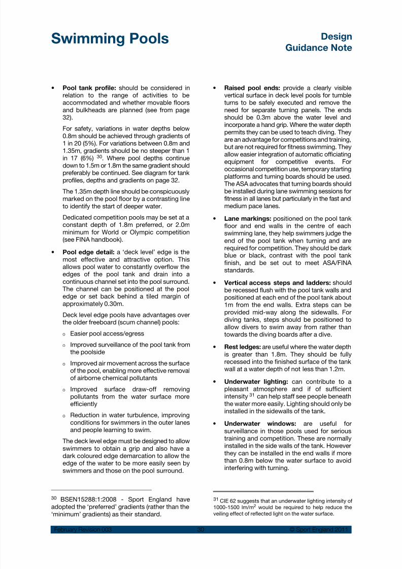
Pool tank profile:• should be considered inrelation to the range of activities to beaccommodated and whether movable floorsand bulkheads are planned (see from page32).
For safety, variations in water depths below0.8m should be achieved through gradients of1 in 20 (5%). For variations between 0.8m and1.35m, gradients should be no steeper than 1in 17 (6%) 30. Where pool depths continuedown to 1.5m or 1.8m the same gradient shouldpreferably be continued. See diagram for tankprofiles, depths and gradients on page 32.
The 1.35m depth line should be conspicuously
marked on the pool floor by a contrasting lineto identify the start of deeper water.
Dedicated competition pools may be set at aconstant depth of 1.8m preferred, or 2.0mminimum for World or Olympic competition(see FINA handbook).
Pool edge detail:• a ‘deck level’ edge is themost effective and attractive option. Thisallows pool water to constantly overflow theedges of the pool tank and drain into acontinuous channel set into the pool surround.The channel can be positioned at the pool
edge or set back behind a tiled margin ofapproximately 0.30m.
Deck level edge pools have advantages overthe older freeboard (scum channel) pools:
Easier pool access/egressO
Improved surveillance of the pool tank fromO
the poolside
Improved air movement across the surfaceO
of the pool, enabling more effective removalof airborne chemical pollutants
Improved surface draw-off removingO
pollutants from the water surface moreefficiently
Reduction in water turbulence, improvingO
conditions for swimmers in the outer lanesand people learning to swim.
The deck level edge must be designed to allowswimmers to obtain a grip and also have adark coloured edge demarcation to allow theedge of the water to be more easily seen byswimmers and those on the pool surround.
Raised pool ends:• provide a clearly visiblevertical surface in deck level pools for tumbleturns to be safely executed and remove theneed for separate turning panels. The endsshould be 0.3m above the water level andincorporate a hand grip. Where the water depthpermits they can be used to teach diving. Theyare an advantage for competitions and training,but are not required for fitness swimming. Theyallow easier integration of automatic officiatingequipment for competitive events. Foroccasional competition use, temporary startingplatforms and turning boards should be used.The ASA advocates that turning boards shouldbe installed during lane swimming sessions for
fitness in all lanes but particularly in the fast andmedium pace lanes.
Lane markings:• positioned on the pool tankfloor and end walls in the centre of eachswimming lane, they help swimmers judge theend of the pool tank when turning and arerequired for competition. They should be darkblue or black, contrast with the pool tankfinish, and be set out to meet ASA/FINAstandards.
Vertical access steps and ladders:• shouldbe recessed flush with the pool tank walls and
positioned at each end of the pool tank about1m from the end walls. Extra steps can beprovided mid-way along the sidewalls. Fordiving tanks, steps should be positioned toallow divers to swim away from rather thantowards the diving boards after a dive.
Rest ledges:• are useful where the water depthis greater than 1.8m. They should be fullyrecessed into the finished surface of the tankwall at a water depth of not less than 1.2m.
Underwater lighting:• can contribute to apleasant atmosphere and if of sufficient
intensity31
can help staff see people beneaththe water more easily. Lighting should only beinstalled in the sidewalls of the tank.
Underwater windows:• are useful forsurveillance in those pools used for serioustraining and competition. These are normallyinstalled in the side walls of the tank. Howeverthey can be installed in the end walls if morethan 0.8m below the water surface to avoidinterfering with turning.
30 BSEN15288:1:2008 - Sport England haveadopted the ‘preferred’ gradients (rather than the‘minimum’ gradients) as their standard.
31 CIE 62 suggests that an underwater lighting intensity of1000-1500 lm/m2 would be required to help reduce theveiling effect of reflected light on the water surface.
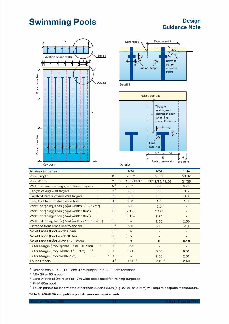
8/14/2019 Swimming Pools Design 2011 Rev3.pdf
http://slidepdf.com/reader/full/swimming-pools-design-2011-rev3pdf 32/97
Swimming Pools Design
Guidance Note
February Revision 003 31 © Sport England 2011
Lane ropes
300
B
A
C
End wall target
A
D
F
Raised pool end
E
E/2 E/2
E
Racing Lane width
H
H
see table
Lane
markings
1 5 m t o
c r o s s l i n e
Detail 1
Key plan
Detail 1
Detail 2
Touch panel J
Elevation of end walls
ll i i I
l . . .
l i . .
i l i , li , . . .
ll . . .
ll . . .
l li . . .
i i l l i . . .
i i l l i . .
i i l l i . .
i i l l i . .
i li ll . . .
l i .
l i .
l i
i l i . . .
i l i . . .
i l i . .
l . . .
i i , , , , . l .
I l
l
i l i l i i .
l l i . . . . . . ill i .
1 5 m t o
c r o s s l i n e
X
Y
Detail 2
Depth to
centre
of end wall
target
The lane
markings are
centred on eachswimming
lane at E centres
All sizes in metres ASA ASA FINA
Pool Length X 25.02 50.02 50.02
Pool Width Y 8.5/10.5/13/17 17/18/19/21/25 21/25
Width of lane markings, end lines, targets A 0.2 0.25 0.25
Length of end wall targets B 0.5 0.5 0.5
Depth of centre of end wall targets C 0.3 0.3 0.3
Length of lane marker cross line D 0.8 1.0 1.0
Width of racing lanes (Pool widths 8.5 - 17m ) E 2.0 2.0 -
Width of racing lanes (Pool width 18m ) E 2.125 2.125 -
Width of racing lanes (Pool width 19m ) E 2.125 2.25 -
Width of racing lanes (Pool widths 21m / 25m ) E - 2.50 2.50
Distance from cross line to end wall F 2.0 2.0 2.0No of Lanes (Pool width 8.5m) G 4 - -
No of Lanes (Pool width 10.5m) G 5 - -
No of Lanes (Pool widths 17 - 25m) G 8 8 8/10
Outer Margin (Pool widths 8.5m / 10.5m)) H 0.25 - -
Outer Margin (Pool widths 13 - 21m) H 0.50 0.50 0.50
Outer Margin (Pool width 25m) H - 2.50 2.50
Touch Panels J 1.90 2.40 2.40
Dimensions A, B, C, D, F and J are subject to a +/- 0.05m tolerance.
FINA 50m pool
ASA 25 or 50m pool
Lane widths of 2m relate to 17m wide pools used for training purposes.
Touch panels for lane widths other than 2.0 and 2.5m (e.g. 2.125 or 2.25m) will require bespoke manufacture.
4
2 3
1
1
1
1
1
1
2
2
5
2
1
3
4
5
5
Table 4 ASA/FINA competition pool dimensional requirements

8/14/2019 Swimming Pools Design 2011 Rev3.pdf
http://slidepdf.com/reader/full/swimming-pools-design-2011-rev3pdf 33/97
Swimming Pools Design
Guidance Note
February Revision 003 32 © Sport England 2011
Examples of tank profiles for 20m and 25m pools
0.9m 0.9m 1.5m1.5m
1.35m
4.0m 5.8m
20.0m
10.2m**
Waterdepth
Waterdepth 1.0m* (0.9m dotted)
1.8m2.0m
6.01m
4.31m 2.01m
@ 1:10
25.02m +/-0.01m (25.0m if no timing pads)
1.35m
For small rural community pools without a separate learner pool, the shallow water depth can be reduced
from 1.0m to 0.9m which is considered more appropriate for young children and teaching.
1.5m water depth allows basic life saving / teaching /training and water based aerobics to be practiced.
Teaching recreational bathing, fitness swimming and training can be accommodated in this profile.
Slopes should not exceed 1 in 17 in water depths less than 1.35m - the gradient should be continued down to
depths of 1.5m where possible.
1.0 to 1.35m is the most useful depth for teaching.
1.8m is the advisable minimum depth for life saving practice.
Races should be started from the deep end of the pool, subject to it being more than 1.35m deep for 6.0m.
Slopes should not exceed 1 in 17 in water depths less than 1.35m - the gradient should be continued down
to depths of 1.5m / 1.8m where possible.
The contour of the floor allows the pool to be used for the teaching of shallow entry dives at the deep end but
is not suitable for other types of diving or the use of diving boards. If diving boards are to be provided then
firstly, the water depth will need to comply with FINA Facilities Rules and secondly the area under the boards
will need to be physically separated from the other activities taking place in the pool, for example, by the use
of a bulkhead and lastly, the separated area will need its own supervision.
Pool surfaces should beclearly marked to indicate the1.35m water depth location
Raised ends forsignificant competitionuse shown dotted
Pool surfaces should beclearly marked to indicate the1.35m water depth location
18.7m**@1:17 gradient
17.0m**@1:17 gradient
** Pool floor gradients in shallow water areas < 1.35m deep shouldbe as gentle as possible but should be < 1:17 (6%)
** Pool floor gradients in shallow water areas < 1.35m deep shouldbe as gentle as possible but should be < 1:17 (6%)
20m pools - general guidance
25m pools - general guidance
* 1.0m is the preferred minimum depth for
tumble turns. 0.9m is acceptable where a
separate learner pool is not provided.

8/14/2019 Swimming Pools Design 2011 Rev3.pdf
http://slidepdf.com/reader/full/swimming-pools-design-2011-rev3pdf 34/97
Swimming Pools Design
Guidance Note
February Revision 003 33 © Sport England 2011
Lane ropes spaced at 2 m centres
for combined teaching/learner pools
13m
7 m
7-13m
13 - 20 m
A
A
0.8m 0.8m
0.6m 0.6m
0.6m0.9m
7 m
Steps should be divided by
handrails and a barrier rail provided
at the ends to prevent children
from jumping onto the steps
0.6m
0.9m
0.6m
0.9m
Decorative tiles spaced at 1.5m
centres along the centre of each lane
Lane rope
Example of a stand alone learner pool layout
Example of a combined teaching/learner pool typical layout
Section A - A Pool Profile.
A
A
Learner and learner/training pools
The ASA recommend that Learner Pools areprovided with an integral movable floor to increaseprogramme flexibility for community use. Refer topage 39 for further details.
The following criteria apply:
Length:• not critical although 13.0m should be the
preferred minimum length and 20.0m is a preferredlength if the pool is also used for training.
Width:• should be wide enough for learners to
make several strokes to get from one side tothe other – 7.0m is acceptable.
Water depth:• 0.6m sloping to 0.8m or 0.9mpreferred across the width if the pool is usedfor training. This can be accommodated invarious layouts.
Colour of tank finish:• white or pale blue.
Pool tank profile:• the shallowest part of the
pool should be at the base of the pool accesssteps, with the pool bottom sloping to itsdeepest point, preferably across the pool width.

8/14/2019 Swimming Pools Design 2011 Rev3.pdf
http://slidepdf.com/reader/full/swimming-pools-design-2011-rev3pdf 35/97
Swimming Pools Design
Guidance Note
February Revision 003 34 © Sport England 2011
Pool tank gradient:• should be no steeperthan 1 in 17 (6%) for water of less than 1.35mand 1:20 (5%) for water less than 0.8m 32.
Pool tank markings:• can be provided for
interest and to space school groups evenlythroughout the pool. These should not be acolour or a shape that could be confused witha child in the water. Markings in lines can helpa child to learn to swim in straight lines.
Access steps and ladders:• ladders must befully recessed. Steps should be positionedalong the length of the pool rather than at thepool end and should be recessed within thepool surround. Steps should be gently gradedwith treads of not less than 0.3m and risers ofapproximately 0.14m. There is a need forhandrails to help children and ambulant
disabled people walk down the steps into thepool.
Pool edge detail:• It is generally agreed that adeck level pool, with the water level the sameas the surround, has advantages. A hand gripfor swimmers and an edge with a distinctivecolour contrast should be provided.
32 ‘BSEN 15288: Part 1: 2008 Swimming Pools: Safetyrequirements for design.’
Learner/training pool with handrails and shallow steps
Diving pools
‘Managing Health and Safety in Swimming Pools’states that as a general principle, when new poolsare being designed, diving stages and springboards
should only be installed over a separate purposedesigned pool.
However, if diving boards are incorporated into a
swimming pool then the area of pool needed forsafe diving will need to:
Be physically separated from all other activities•taking place in the pool e.g. a movablebulkhead
The water depth will need to comply with FINA•Facilities Rules for Diving
The diving area will need its own independent•supervision.
The addition of a movable floor can also increaseflexibility.
The following criteria apply:
Minimum dimensions:• the tank and theboards should conform to the minimumdimensions set out in the FINA Facilities Rulesfor Diving. However, the preferred dimensionsshould be adopted where possible. ForOlympic pools, the preferred dimensionsbecome the minimum requirement.
A movable floor will allow the pool to be usedfor a wider range of activities but if provided, thetank depth should be increased to accommodatethe movable floor. The overall dimensions could
be increased to suit the other activities, such assynchronised swimming and water polo.

8/14/2019 Swimming Pools Design 2011 Rev3.pdf
http://slidepdf.com/reader/full/swimming-pools-design-2011-rev3pdf 36/97
Swimming Pools Design
Guidance Note
February Revision 003 35 © Sport England 2011
ASA/FINA Diving Requirements (Plan)
3m springboard
3m springboard
1m springboard
1m springboard
3m & 7.5m platforms
(stacked)
10m platform
1m & 5m platforms
(stacked)
3m springboard
3m springboard
1m springboard
1m springboard
7.5m platform
10m platform
5m platform
3m platform
1m platform
1m springboard
3m springboard
Examples of dedicated diving tank layouts (incorporating synchronised diving).
FINA standards recommend that diving platforms are not stacked above each other, but in the event that this is unavoidable,
clearances and set-back of plummet lines need to be provided. This maybe a requirement where pool size does not allow
springboards to be located opposite the platforms.
Preferred diving pool size 25m x 21m or 25m for two sided use (right hand example above). Other formats depend upon available
space - a minimum diving tank to accommodate a full range of diving platforms and twin 1m and 3m springboards will be 25m
x 15.75m based upon minimum FINA standards and stacking (left hand example above).
The ASA required diving provision is for 3m wide platforms at 3, 5, 7.5 and 10m levels and 2No. 1m and 3m springboards being
the minimum requirement to accommodate synchronised diving at training and competition levels but preferably there should
be 3No. 1m and 3m springboards where possible. However the level of provision will depend upon the pool size and spaceavailable. Harness rigs should be provided for one 1m and one 3m springboards for training purposes.
Colour of tank finish:• walls can be white orpale blue. A dark-blue floor is preferred as this,in conjunction with agitation of the watersurface by water sprays, assists divers inseeing the water surface and will minimiseaccidents.
Pool tank profile:• dimensions will be
determined by FINA requirements and whethera movable floor is installed. Where the divingtank also acts as a 25m training pool, the lanemarkings should be provided in a colour whichcontrasts with the floor of the pool. Themakings should be 0.2/0.3m in width and eachlane shall end 2m from the end walls of thepool with a distinctive cross line 1.0m long.Target lines should be provided on the endwalls in the centre of each lane. These shouldextend without interuption to the floor of thepool and have a cross line 0.5m long 0.3mbelow the surface of the water.
Pool edge details:•
Should be level with thewater (i.e. without a raised hand grip lip) tohelp swimmers maintain contact and balancebefore diving. Raised sections of the surround
with a flat edge can also be helpful for teachingand coaching.
Ladders and steps:• should be recessed. Theyshould be positioned to encourage divers tofollow a safe route to rapidly exit the waterafter completing their dives, while avoiding thedanger areas of other boards.
The type and positioning of steps will be affectedby the board layout, other activities accommodatedin the pool and whether a movable floor isplanned.
Rest ledges:• if provided, must be fully recessedat a water depth of not less than 1.2m.
Surface agitators:• a FINA requirement to helpdivers in their visual perception of the watersurface. Normally the agitation is made via watersprays and directed on to the surface of thewater.
Bubbler:•
a ‘bubbler’ is installed on the poolfloor to provide a compressed air cushion ofbubbles to help protect divers from injury.

8/14/2019 Swimming Pools Design 2011 Rev3.pdf
http://slidepdf.com/reader/full/swimming-pools-design-2011-rev3pdf 37/97
Swimming Pools Design
Guidance Note
February Revision 003 36 © Sport England 2011
platform
platform
Lifeguard Position
Danger area
Danger area
Danger areaplatform
*
ASA/FINA diving requirements (Section)
Platform
Platform
Plummet
line
Plummet
line
3m Springboard
1m Springboard
ASA/Fina diving pool requirements vary depending upon diving height and board/platform
layout and setting out - refer to tables produced by the ASA/FINA.
It is common for a rectangular diving tank to be used with a movable floor to allow more flexible use
of the pool, rather than the profile shown within the ASA/FINA standards, provided that the pool fullfilsthe dimensional requirements.
ASA/FINA recommend that diving platforms are not stacked aboveeach other. However, where this is unavoidable the lower platforms
are set back up to 1.25m, whilst still maintaining the distance back to
the pool wall. This may impact upon the pool tank size.
0.75 - 1.25m
0.75 - 1.80m
9 - 13.5m
Lateral spacings between platforms, spring
boards and pool sides vary substantially and
depend upon FINA standards and board heights
Platform
under platform
Platform or
springboard
Ensure that ASA/FINA headroom clearancestandards (shown dotted) are followed as these
are substantial, and will impact on diving layout
and roof structure design & height.
Underwater lighting, windows and•
surveillance: see page 30.
Training Harnesses:• consideration should begiven to the provision of training harnessesattached to the roof structure for some of theboards.
Shower and spa pool:• used by divers to warmup and relax muscles while out of the water forlong periods.
Dry land training area:• an estimated 30% ofdiver training is in a dry springboard trainingarea. Ideally situated adjacent to the divingpool and equipped with trampolines, dryboards with foam landing areas, weight
The diving pool overalldimensions could be
increased to suit other activities, such as synchronised swimming and water polo.
Arrows show the quickest and safest route from thedanger areas.
training area and training harnesses.
Lighting:•
should be an even level of 600 luxmeasured at 1.0m above the surface of thewater. Glare/specular reflection on the watersurface must be avoided. A similar standard oflighting should be provided in the dry landtraining area.
See FINA web site for current dimensions for divingfacilities.

8/14/2019 Swimming Pools Design 2011 Rev3.pdf
http://slidepdf.com/reader/full/swimming-pools-design-2011-rev3pdf 38/97
Swimming Pools Design
Guidance Note
February Revision 003 37 © Sport England 2011
Easy access to the water
An appropriate combination of recessed ‘easygoing’ steps, recessed ladders, ramp, submersibleplatform and / or hoist should be provided to alloweasy access to and from the water for all users. Inthis respect deck level pool surrounds arepreferred.
See separate Sport England Design GuidanceNote ‘Accessible Sports Facilities’ for furtherdetails.
Pool transfer aids should be provided for all pools.The type of aid will depend on the needs of theuser, however all pools should provide ademountable hoist and a metal socket fixingmounted into the pool surround.
A permanent ramp or walk-in steps are thepreferred option to assist wheelchair users andpeople with walking difficulties. Portable steps/ stairs should not be seen as an alternative, but partof the standard equipment to help particular peoplewith disabilities.
Recessed ‘easy going’ steps allow easy access to and from the water for all users
Ramp access and projecting platform adjacent to ateaching area in a specialist pool

8/14/2019 Swimming Pools Design 2011 Rev3.pdf
http://slidepdf.com/reader/full/swimming-pools-design-2011-rev3pdf 39/97
Swimming Pools Design
Guidance Note
February Revision 003 38 © Sport England 2011
Table 5 Pool Equipment taken from Sport EnglandGuidance Note: Accessible Sports Facilities
Typical assisted pool hoist to provide access to the water
A submersible pool surround lift integrated into the poolas part of the pool surround can provide a dignifiedaccess to the pool for wheelchair users
Self-propelling waterproof 1 2 3 * *
chairs (min)
Poolside hoist l l m (single position)
Poolside hoist m m l l l (multiple position)
surround lift m m m m m
Mobile hoist m m m m m
Portable easy going steps m l l l
Minimum number of 4 4 8 * *
full-height lockers
chair accessible lockers4 4 8 * *
Changing mats l l l * *
Key: lRequired m Recommended
* As main pool provis ion
2 0 m s
w i m m
i n g p o o l
2 5 m s
w i m m
i n g p o o l
5 0 m s
w i m m
i n g p o o l
L e a r n e r p o o
l
D i v i n g t a n k
Submersible pool
Minimum number of wheel-

8/14/2019 Swimming Pools Design 2011 Rev3.pdf
http://slidepdf.com/reader/full/swimming-pools-design-2011-rev3pdf 40/97
Swimming Pools Design
Guidance Note
February Revision 003 39 © Sport England 2011
Movable floors and bulkheads
Movable floors are being used more extensively tochange the water depth over part or all of the pooltank area in order to achieve greater programmingflexibility. They allow more activities to beaccommodated within a single pool area orimprove activities that may be compromised by afixed depth of water.
There is evidence of greater through-put andreduced net operating cost where they are used,particularly for 50m pools.
The use of this technique to create a ‘dry’ activitiesspace is usually limited by the wet humid conditionswithin the pool hall. However learner pool floors,which can be raised to the level of the pool decksurround, are sometimes used as a holding areafor competitors when an event is taking place inthe main pool.
Movable floors can be adjusted from a depth of afew centimetres for carer and baby classes to asafe depth of 5.0m for a person diving from a10.0m diving board.
With a main pool and learner pool configuration asrecommended by the ASA there are a number oflocations in which a movable floor can provide
benefits.Where a movable floor is provided as part of alearner pool, automatically folding steps (as shown
in the illustration) can be integrated with themovable floor to allow mother and child, or thosewith ambulant disabilities, to access the pool withgreater ease, regardless of its set depth.
There are two types of bulkheads – those whichtraverse laterally and when not in use are stationedat one end of a pool, and those which movevertically and when in their lowered position arehoused in a recess in the pool floor.
Bulkheads can be used to:
Divide the water area so it can be used for•
different activities simultaneously. This is oftendesirable for safety reasons.
Reduce the length of an existing pool to 25m,•
The bulkhead allows divided simultaneous use of two areas of a single swimming pool
Movable floors allow a wide variety of uses
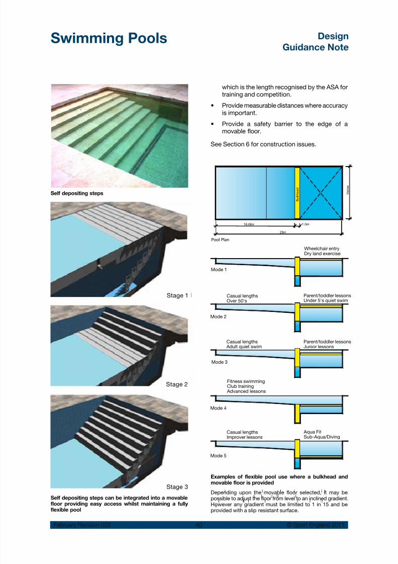
8/14/2019 Swimming Pools Design 2011 Rev3.pdf
http://slidepdf.com/reader/full/swimming-pools-design-2011-rev3pdf 41/97
Swimming Pools Design
Guidance Note
February Revision 003 40 © Sport England 2011
which is the length recognised by the ASA fortraining and competition.
Provide measurable distances where accuracy•is important.
Provide a safety barrier to the edge of a•movable floor.
See Section 6 for construction issues.
Self depositing steps can be integrated into a movablefloor providing easy access whilst maintaining a fullyflexible pool
Examples of flexible pool use where a bulkhead andmovable floor is provided
Depending upon the movable floor selected, it may bepossible to adjust the floor from level to an inclined gradient.However any gradient must be limited to 1 in 15 and beprovided with a slip resistant surface.
Stage 1
Stage 2
Stage 3i l l i i l
l l i l i i
i li i i i i li
i
V a r i e s
16.66m 1.0m
25m
Fitness swimmingClub training Advanced lessons
Casual lengthsOver 50's
Parent/toddler lessonsUnder 5's quiet swim
Casual lengthsImprover lessons
Aqua FitSub-Aqua/Diving
Casual lengths Adult quiet swim
Parent/toddler lessonsJunior lessons
Wheelchair entryDry land exercise
Mode 1
Mode 2
Mode 3
Mode 4
Mode 5
Pool Plan
B u l k h e a d
Self depositing steps

8/14/2019 Swimming Pools Design 2011 Rev3.pdf
http://slidepdf.com/reader/full/swimming-pools-design-2011-rev3pdf 42/97
Swimming Pools Design
Guidance Note
February Revision 003 41 © Sport England 2011
4.5 Changing facilities
Swimming pool changing can be designed witheither open-plan single-sex areas or as a ‘villagechanging’ unisex area with individual cubicles.
The village changing arrangement is usuallypreferred for the various modes of use. Villagechanging can provide:
Greater flexibility to accommodate varying•mixes of male and female users, includingfamily changing and changing for people withdisabilities.
Flexibility to allow staff of either sex to•supervise, clean and maintain the area 33.
Minimise any perceived sense of insecurity for•sensitive users 34 by well designed changingrooms that offer privacy through adequatelysized, good quality cubicles.
There is scope for variations in both systems withthe addition of group single sex changing rooms,buffer rooms and additional cubicles that arediscussed later. This can give a degree of choicefor user groups. It is recommended that early
consultation takes place with stakeholder groupswith a view to understanding the full requirementsof all user groups.
Changing areas often attract criticism in otherwisewell-designed facilities. The key issues are:
Adequate spatial allowance for users to•maintain a sense of personal space
Capacity to cope with peak times, without•pinch points, particularly between cubiclesand lockers
A flexible layout for varying ratios of male and•female users
Areas that can be closed off for privacy for•sensitive groups with direct access to toilets / pre-cleanse / pool water
A suitable environment avoiding extremes of• humidity, air movement (draughts) andtemperature
Simple and clear circulation routes between•point of entry and the pool hall
Well designed cubicles and lockers with•suitable materials and robust fittings which,together with good supervision, help to resistvandalism
A number of hose points to limit the length of•hoses and adequate falls to drain to aidefficient cleaning and maintenance of the
changing, toilet and shower areas.
Design features that can help to achieve bright,crisp and airy surroundings for users include:
A strategic use of natural top lighting e.g. roof•lights can improve the appearance of thechanging area and may minimise the use ofartificial lighting.
Bright and warm artificial lighting and•maximising the ceiling height.
Use of bright contrasting colours to walls,•cubicles, lockers, signage and graphics.
33 A variation, used in some European facilities separateswet and dry circulation. This needs more space and thelayout can be confusing but has advantages in reducing themigration of dirt into wet areas, selection of appropriateflooring and the cleaning of the floor.
34 See Women Sports Foundation UK.http://www.wsf.org.uk/
http://www.whatworksforwomen.org.uk/
It is recommended thatearly consultation takes
place with stakeholder
groups with a view tounderstanding the full requirements of allusers.
Village changing with view from the pool side

8/14/2019 Swimming Pools Design 2011 Rev3.pdf
http://slidepdf.com/reader/full/swimming-pools-design-2011-rev3pdf 43/97
Swimming Pools Design
Guidance Note
February Revision 003 42 © Sport England 2011
General planning principles
For ease of operation and supervision organise•the route from reception to the pool in a logicalsequence.
Make vanity areas spacious enough to prevent•congestion close to the entrance. Take intoaccount bathers entering and leaving inaddition to those using the vanity area.
Make space close to the entry point and within•
sight of the reception for storage and parkingof baby buggies, prams and wheelchairs. Alsomake adequate space allowance for theirstorage within the changing area.
Ensure that single-sex changing areas and•toilet provision are well screened from commonareas for privacy.
Plan the layout to allow effective surveillance•by staff.
Through routes need to be clearly defined and•lockers should be positioned in close proximityto the changing benches or cubicles.
Position toilets on the access route to the pool•and ensure pre-swim showers are locatedafter the toilets and immediately prior to theentry into the pool hall.
Pool changing should not be combined with drychanging. Pool changing areas generally havehigher temperatures and humidity, lack individualshowers, and are more difficult and expensive tokeep clean.
To avoid cleaning problems, minimise repetitivecirculation where users from the wet side use the
same routes as those from the dry side.
Changing layouts
The following diagrams show typical arrangementfor single sex changing and changing village.
Single-sex open-plan changing accommodationshould allow flexibility to manage variations inmale/female mix ratios. This can be achieved withgroup changing rooms located between thechanging rooms, with interlinking lockable doors,to become ‘buffer’ changing that can be quicklyallocated to either male or female use.
Some user groups will have specific requirements.For example, a school pool will require more groupchanging rooms, a specialist pool for people withdisabilities will require mainly large accessiblechanging cubicles with minimal group changing.Specific requirements should be determined byappropriate consultation prior to preparation of thebrief.
A standard changing village with cubicles could bedivided up into dedicated zones for male or femaleuse for particular programme sessions.
Lockable group or team changing rooms for schoolclasses, competition and club use can be includedas an additional facility. They can also be used asan overflow facility during busy periods.
At off-peak times, the buffer or group rooms willremain locked unless needed for school or groupuse. At peak times they can be opened up toprovide overspill male or female changing.
The changing village is the preferred option formost new pools and a number of existing poolshave converted from single-sex changing tomixed-sex changing villages. For most communityswimming pools a mixed-sex changing village withat least two lockable group changing rooms offersthe most cost-effective and easily managedarrangement.
Signs must give clear information using lettering whichcontrasts clearly with it’s background to improvevisibility and reassurance to users. Braille should be
incorporated and imagery is also beneficial

8/14/2019 Swimming Pools Design 2011 Rev3.pdf
http://slidepdf.com/reader/full/swimming-pools-design-2011-rev3pdf 44/97
Swimming Pools Design
Guidance Note
February Revision 003 43 © Sport England 2011
Table 6 Analysis of types of changing room layouts
Function Mixed-sex village changing Single-sex, open plan changing areas
Usability Advantages
Simple, direct circulation routes with views to andfrom the pool and other areas.Individual privacy.Cubicles popular with women (if designed toallowing sufficient personal space and feelingsecure and well supervised).Layout can be designed to ensure users passtoilets and showers.
Adjacent lockable group changing rooms can alsogive additional capacity at busy times.
At quiet times, users may use as much spaces asthey wish.
Vacant changing spaces can easily be identified.School groups can be more easily supervised.Layout can be designed to ensure users passtoilets and showers.Buffer rooms can be used for lockable groupschanging.Popular with club groups.
Disadvantages Can be difficult to find a vacant cubicle.Might be difficult for school groups to besupervised and there is the additionalcomplication of storing pupils clothes in the
lockers.More mingling of fully clothed and wet users.
Less open circulation routes to and from the pooland other areas.Lack of individual privacy.Cubicles may be required in addition.
Privacy barriers required at point of entry to thechanging room and at the pool hall and makesmore complex and restricted circulation pattern.
Flexibility Advantages
All changing spaces and lockers are available toall users giving flexibility to accommodate anyproportion of male and female users.Parents can share a cubicle with children ofopposite sex.Family groups can change together.
Individual bench changing spaces are not definedmaking it possible to accommodate more usersduring busy periods.
Disadvantages Location of toilets may cause repetitive/ cross-circulation where rows of cubicles andlockers open directly into the pool hall.
Unless buffer changing rooms are provided, thereis no flexibility to accommodate differentproportions of male and females.Family changing with parents and children ofopposite sex is impossible, except for youngchildren. Provision may need to be providedelsewhere.
Accessibility Advantages
Helpers can accompany people with disabilities ofopposite sex.Some cubicles can be sized to give privacy topeople with disabilities.
Sufficient free space can be provided so thatpeople with disabilities can move easily aroundthe changing area.
Disadvantages It can be difficult for people with disabilities tomove around in the cubicles and changing areas.
People with disabilities require an assistant oftheir own sex.More complex circulation caused by privacyscreens can restrict circulation.
Cleanability Advantages
Row of cubicles can be taken out of use duringcleaning (subject to the layout and the location offloor drainage gullies).
Large, relatively uncluttered floor areas should beeasier and quicker to clean.If buffer changing rooms are provided these canbe locked during off peak times.
Disadvantages Cleaning has to be confined to relatively smallareas at a time and may take longer because of
the need to work around cubicles and their supports.
Large open-plan areas may be more difficulty toclose off at times of low demand.
Manageability Advantages
Staff of either sex can supervise, clean andmanage the entire changing area.
The entire changing area is normally visible andcan be easily supervised.
Disadvantages There can be hidden areas that are difficult tosupervise.
Requires two members of staff of opposite sex tosupervise the two areas and to deal withproblems such as the opening of lockers.
Capital cost Advantages
Minimum number of lockers required. Additional lockers required for different peakdemands of a particular sex.
Disadvantages More space per person for a cubicle based layout.
Operating costs Advantages
Reduced staffing cost for supervision.
Disadvantages Cubicles require additional maintenance. Staff of both sexes required for supervision.Cannot be supervised from the pool side.

8/14/2019 Swimming Pools Design 2011 Rev3.pdf
http://slidepdf.com/reader/full/swimming-pools-design-2011-rev3pdf 45/97
Swimming Pools Design
Guidance Note
February Revision 003 44 © Sport England 2011
Calculating numbers
The standard methodology for assessing themaximum number of changing spaces required isbased on:
Number of spaces required for a steady state•condition i.e. when there is a steady flow ofbathers into and out of the pool.
Additional spaces to accommodate call-out•groups: more commonly referred to as sessiongroups. During peak periods the time spent inthe pool may have to be limited and this isnormally achieved by giving bathers a colouredwrist or ankle band. Each session has a set
minimum time after which the users are ‘calledout’ of the pool depending on their band colourto make way for others.
Table 7 Accessible changing and toilet provision
2 0 m C
o m m u n i t y P o o l
2 5 m C
o m m u n i t y /
C o m p e t i t i o n P o o l
5 0 m C
o m p e t i t i o n P o o l
Accessible Changing Provision for Pool Use
Unisex accessible changing room with wc l l 2*
In addition provide an accessible changingcubicle within the main changing area
m l l
In addition to provide a unisex ‘ChangingPlaces’ changing room that can be accessedfrom the pool changing area
m l l
Disabled / Family cubicles within the mainchanging area
2 4-6 6-8
Accessible Toilet Provision in Pool Changing Areas
Dedicated Unisex Accessible WCcompartment on each floor (in addition toany provision within unisex accessiblechanging above)*
m l l
Provide a minimum of at least one cubicleeach within the general male and female toiletssuitable for an ambulant disabled person
m l l
Accessible Toilet Provision serving Public /Non-changing Areas
Unisex Accessible WC compartment on eachfloor (in addition to any provision within unisexaccessible changing above)*
l l l
Changing Places provision: accessible frompublic spaces
m l l
Key: l Required m Recommended
Notes:
See ‘Accessible Sports Facilities’ for details of the layouts forthe above facilities.
* The above figures are the minimum and should be increasedif necessary to reflect the anticipated amount of use and the
relationship to the individual facilities. Unisex accessiblechanging facilites must be located wherever there is generalchanging provision.
An allowance of 10% for changing spaces•
temporarily out of use, for example for cleaningduring busy times.
Deciding upon the proportions of single,•double and family/disabled changing cubiclesand single sex areas with buffer changingzones.
Additional group changing for schools and•swimming clubs or as an additional bufferarea.
A typical calculation is shown in Appendix 3.
The operator’s views should be sought on factorssuch as:
Proposed programme of activities•
Appropriate pool capacity•
Average swim-time•
Number of session call-out groups to be•accommodated.
The general disposition of spaces for a changingvillage should allow for equal numbers of singleand double sized cubicles and for changing roomsfor family groups and people with disabilities.
Village changing circulation areas should be generousto allow circulation during peak times

8/14/2019 Swimming Pools Design 2011 Rev3.pdf
http://slidepdf.com/reader/full/swimming-pools-design-2011-rev3pdf 46/97
Swimming Pools Design
Guidance Note
February Revision 003 45 © Sport England 2011
The dispersal of locker is the preferred option,located close to where people change. However,concentration allows staff supervision and bettersecurity, but bathers have to carry their clothes agreater distance and with children in particularthere is a risk of dropping them on a wet floor.
Clear views fromchanging cubicles and
lockers assist customerorientation.
Locating lockers oppositecubicles reduces the riskof dropping clothes onto awet floor.
With a single-sex, open-plan arrangement a certainamount of concentration is inevitable as the onlyway to cater for varying numbers of male andfemale users is to provide single-sex changing witha mixed-sex locker area.
If this is not provided each open-plan area will
need sufficient lockers to accommodate themaximum possible number of users in the pool,taking into account people using buffer changingduring public sessions.
Lockers in buffer or group changing rooms are notrecommended since they cannot easily besupervised and may be a target for vandalism.
Benches, coat hooks and lockers
Benches should be cantilevered wherever possibleas it is difficult to clean floor areas around benchfeet. Proprietary systems with cast aluminium orgalvanised steel supporting brackets are availablewith either hardwood or solid laminate slats.
Vandal-resistant clothes hooks with shortprojections should be selected and securely fixedto the walls.
The number of lockers required should becalculated based upon:
75% of maximum pool occupancy (up to 25%•
of pool users will share a locker)
Add 100% of the changing room occupancy•
Add 10% to cover for lockers out of use e.g.•through broken locks or lost keys.
See typical calculation example in Appendix 3.
Lockers are generally manufactured in columns ofapproximately 1.8m high x 0.3m wide x 0.5–0.6mdeep. This will provide a full-height unit or can besplit by intermediate dividers into smaller, individuallockers: half, third or quarter height units. However,in order to accommodate sports bags a proportionof the lockers should be at least 0.4m wide.
A general rule is to provide half-height units for50–70% of the total locker provision with thebalance split equally between quarter and fullheight units.
Some lockers should be large enough to store acollapsed pushchair or for people with disabilitieswishing to store artificial limbs or walking aids 35.
Cantilevered benches in a group changing room alloweasy cleaning of the floor. A wall hung heating sourceis located under the bench
35 See Separate Sport England Design Guidance Note‘Accessible Sports Facilities’ for recommendations on the
numbers of full height lockers.
See www.inclusivefitness.org for approved lockermanufacturers.

8/14/2019 Swimming Pools Design 2011 Rev3.pdf
http://slidepdf.com/reader/full/swimming-pools-design-2011-rev3pdf 47/97
Swimming Pools Design
Guidance Note
February Revision 003 46 © Sport England 2011
Example 2:Separate male and female changing areas with integrated accessible changing and toilets and individual cubicles forfamilies and wheelchair users
Example 1:
Alternative example of a changing village (unisex cubicle changing) with integrated accessible changing and toiletsincluding the unisex ‘Changing Places’ room
Note:
Changing areas may be open to the pool areato allow direct views. However barriers shouldbe incorporated to prevent smaller childrenaccessing deeper pool water areas straightfrom the changing room and users havingdirect access without passing through thepre-cleanse shower zone.
Key:
Family / disabled accessible
changing cubicle
F/D
Unisex accessible changing
room with WC
D.Ch/WC
Changing Places FacilityCPF
Unisex accessible WCDWC
Unisex accessible shower
cubicle
D.Sh
Cleaners store
Baby change
Cl. St
BC
Pre-swim showers
Post-swim shower
Vanity area
Pre.S/Sh
Sh
V
F/D
F/D
D.Sh
FWCF/D
Sh Sh
Pre.S.Sh Pre.S.Sh
Sh Sh Sh
Sh
Sh
V
DWC
/ BC
BC
BC
D.Ch / WC
MWC
Cl.St
Poss. M/F separation point
Female zone Male zone
V
Main pool Learner pool
to enable separate group ch.
V V V
Optional returns walls
to preswim showers
Group Changing
(20p)
Group Changing
(20p)CPFF/D
MWCFWC
Group 01
(20p)
Group 02
(20p)
V V
F/D
F/D
F/D
F/D
Female
Changing (42p)
Male
Changing (42p)
D.Sh D.ShSh
Pre.S.Sh
Sh Sh Sh
DWC
D.BC
BC BC
BCCh/WC D.Ch/WC
DWC Cl.St.
Learner PoolMain Pool
i i l il i
l ii l
ili i i
i ii i
l i
CPF
The additional ‘ChangingPlaces changing room’
(as tables 8/9 in Accessible SportsFacilities design
guidance note) isseparated with directaccess to the pool side.

8/14/2019 Swimming Pools Design 2011 Rev3.pdf
http://slidepdf.com/reader/full/swimming-pools-design-2011-rev3pdf 48/97
Swimming Pools Design
Guidance Note
February Revision 003 47 © Sport England 2011
1.5m
1.5m
2m
2.5m
1.5m
1.5mMinimum
2m1.5m
2.6m minimum
3.1m preferred
2m
1.5m
2.5m
1.5m
1.25m
2m
2.2m1m1m
2m
300mm
preferably
500mm
1m wide
door set
3.1m
0.6m
0.6m
0.5m
Buffer locker
Buffer change
Lockers
Lockers
Seating
Seating
Seating
1m wide
door set
VanityVanity
0.9m
Buggy
storage
area
Buggy
storage
area
Single person
cubicles 1.0 x 1.1m
Family/Accessible sized
cubicles 2 x 2.2m,
preferably 2 x 2.6m
Shower heads at
750mm centres
1.5m
1.5m
Lockers
Two person cubicle
1.1m x 1.5m
Disabledshower cubicle
Lockers
2.4m min
2.5m
Preferred minimum dimensions for changing/locker room layouts

8/14/2019 Swimming Pools Design 2011 Rev3.pdf
http://slidepdf.com/reader/full/swimming-pools-design-2011-rev3pdf 49/97
Swimming Pools Design
Guidance Note
February Revision 003 48 © Sport England 2011
BS 6465: Part 1: 2006 – Table 12 – Minimum provision of sanitary appliances for swimming pools
See Appendix 3 for an example
Sanitary appliance For male pool users For female pool users
WC 2 for up to 100 males; plus 1 for every
additional 100 males or part thereof
1 per 5 females up to 50 females1; plus 1
for every additional 10 females or part
thereof up to 100 females; plus 1 per 50
females or part thereof thereafter.
Ambulant WC cubicle At least 1 ambulant accessible WC cubicle (min 800 mm wide) for ambulant disabled
people should be provided in separate sex toilets.
Wider ambulant WC
cubicle
Additionally to the above ambulant accessible WC cubicle provision, where there are
four or more WC cubicles in a toilet ( in addition to the unisex facility), 1 wider WC
cubicle 1200 mm wide, for people who need extra space should be provided in both
male and female separate sex toilets.
Urinal 1 per 20 males up to 100; and 1 per 80
males or part thereafter
–
Washbasin 1 per WC, plus 1 per 5 urinals or part thereof 1, plus 1 per 2 WCs or part thereof
Shower 1 per 10 males or part thereof 1 per 10 females or part thereof
Nappy changing This may be a nappy changing bench and disposal bin in an area adjacent to a WC and
washbasin, or in one or more dedicated parent and child toilets. Where baby changing
facilities are provided, they should be accessible to disabled people.
Cleaners sinks and storage 1 per each 100m2
Vanity places 1 per 30 lockers for men and 1 per 20 lockers for women.
1 Where female pool users will not be using the pool in timed sessions, i.e. will not be changing at the same time, 1 WC per 10females will be acceptable.
Toilets
Toilets should generally be provided in accordancewith BS 6465: 2006 Part 1 table 12 36. They shouldbe sited in a prominent position on the route from thechanging area to the pool hall, before any pre-swimshowers. This can be difficult to achieve with amixed-sex changing village layout where thecirculation routes between rows of changing cubiclesmay lead directly onto the pool surround. Somerepetitive circulation is inevitable as the toilets arenormally located to one side of the changing area.
Separate-sex toilets are required and need to bedesigned to accommodate users with disabilities.In small pools it is more economical to provide aseparate accessible unisex WC compartment.This can be planned with access from the poolsurround. The toilet design/layout should ensure:
The toilet and urinal area is screened for privacy•
There are no hidden areas to hinder staff•supervision
There is sufficient circulation space to enable•easy access for wheelchair users
Regular cleaning with a hose•
Robust and vandal proof fittings.•
Showers
Shower provision should be in accordance with BS6465 Part 1 Table 12 and based on a 50% maleand 50% female use of the pool. For reasons ofswimming water hygiene, pre-swim showersshould be positioned to encourage them to beused prior to pool entry.
In contrast post-swim shower cubicles should bepositioned as close as possible to the lockers in aunisex village change area or within individual maleand female changing areas so that swimmers canconveniently retrieve their soap and towels. In amixed sex changing village the pre and post swimshowers can be positioned close to each other,adjacent to the pool surround.
Where cost is a factor, showers can cater for bothpre and post swim needs in one area. They can beplanned close to the pool hall or in a recess off thepool surround to allow indirect staff supervision.
Attention should be given to adequate drainageand slip resistance of the floors to shower areas toprevent soap creating a hazard 37.
37 Slip resistance should take into account the HSE Slipsand Trips Information Sheet: ‘Assessing the slip resistanceof flooring’.
36 This version of the standard creates some anomalies andsome reductions may be appropriate subject to agreementwith the Local Authorities. See notes in Appendix 3.
Table 8

8/14/2019 Swimming Pools Design 2011 Rev3.pdf
http://slidepdf.com/reader/full/swimming-pools-design-2011-rev3pdf 50/97
Swimming Pools Design
Guidance Note
February Revision 003 49 © Sport England 2011
Footbaths are not considered an effective methodof cleaning feet and are an impediment to disabledpeople. Foot sprays are an alternative, althoughwell-positioned showers that encourage use priorto swimming are the best option. The showerdesign and layout should ensure:
Adequate warm water consistent with water•economy.
Dirty water is prevented from entering the pool•or, in a deck level pool, the surround channel.
Showers are not planned with stepped•thresholds and use good falls and floordrainage channels or gullies to remove water.
Vanity areas
Vanity areas are also covered by BS 6465 Part 1being calculated as a proportion of the lockerprovision. They can operate as mixed sex-areas,but should be generously sized to cater for throughtraffic and peak use.
The following equipment should be provided:
Hand-held hair dryers•
Well-lit mirrors•
A shelf, at least 300mm deep, to accommodate•bags and small items such as combs.
Mirrors and shelves should be located for ease ofaccess by people of all heights including wheelchairusers.
4.6 Ancillary accommodation
Office accommodation
The extent of office accommodation will varyaccording to the size of the building, the level ofadministrative duties and whether other on-siteaccommodation can be used, for example, schooland college offices or the staffroom.
A local neighbourhood/community centre housinga 20 or 25m pool and sports hall requires:
Manager’s office large enough to accommodate•up to six people.
Duty officer’s accommodation with work•stations for up to three people.
General office, either separate or linked to the•reception desk, with a workstation for oneperson.
A number of fully enclosed showers for•post-swim showering.
There are waste receptacles close to the•shower area for empty shampoo bottles andsachets.
Drop-down shower seats are provided for•
users with disabilities.
Showers en route to the pool with banks of lockers
Circulation areas associated with changing facilitiesshould not be restricted
Solid laminate panels for use in shower areas

8/14/2019 Swimming Pools Design 2011 Rev3.pdf
http://slidepdf.com/reader/full/swimming-pools-design-2011-rev3pdf 51/97
Swimming Pools Design
Guidance Note
February Revision 003 50 © Sport England 2011
In a small pool building on a school or college sitea combined reception desk/office should besufficient. A space of 3.5 x 2.5m can accommodatetwo or three people.
Larger facilities may need more extensive provisionand the pool operator should be consulted early inthe design process in order to tailor the design tosuit operational needs.
Staffroom and changing
Staff accommodation should be independent frompublic facilities and located away from the mainactivity areas. It should be easily accessible andlocated so that staff can respond quickly if called
to an emergency. A local neighbourhood pool should include a smallrestroom with tables, chairs, sink/drainer unit,cupboards and small cooker including amicrowave. Individual lockers should be providedfor staff. Other needs may be met by publicfacilities.
A larger centre will require individual male andfemale changing rooms and should include benchseating, lockers, a staff shower or shower cubicles,and toilets. Dedicated accessible changingprovision should also be made for staff withdisabilities.
Cleaners store
For storage of cleaning equipment and materials,and provision of a cleaner’s sink, see BS 6465Part 1.
External service yard
A secure external service yard should be providedfor refuse storage. Refuse bins can be vandalisedby fire and should be located to prevent firespreading to the main building. The bins should bescreened and the area can be combined withaccess to the plant room to form a service delivery/
storage area.
First aid room
The first aid room should be directly accessiblefrom the poolside with separate external accessto a parking area for emergency vehicles. Doorwaysshould provide a minimum clear width of 1.1m,and be positioned to allow stretcher access.
A minimum area of 9.0–10.0m2 is recommended,excluding any toilet provision. Space for a couchor stretcher trolley, stretcher, chair, sink andlockable wall cupboard should be provided.
The couch should be located with access spaceon all sides, and not be located against a wall. Theprovision of an en-suite accessible toilet would
also be useful. In pools where major competitionstake place this would allow the first aid room todouble as a doping control room.
Pool equipment store
The pool equipment store should be directlyaccessible from the poolside and have sufficientspace for storage of swimming aids, float lines,starting blocks, backstroke warning flag lines, falsestart recall line and lane ropes, depending on thedepth of the pool and whether it is used forcompetition and training.
Swimming aids can be stored in movable trolleysinside the store. Lane ropes can be stored on reelson the pool surround as long as the minimum poolsurround widths are not compromised.
Alternatively, lane ropes may be stored in a hopperlocated in an undercroft beneath the pool surround(see photograph below).
Storage space may be needed for water pologoals, pitch markings and timing panels. Additionalspace may also be required for stackable chairsand podia for competition events. It should beassumed that all equipment may get wet - the
store area should have a well drained tiled floorand adequate ventilation to remove smells andprevent corrosion of the stored equipment.
Stretcher trolley/bed
Equipment cupboard
Direct access toemergency vehicles
1.1m clear minimum
Sink, base unit andlockable wall unit.
Chair
600mm clear access zonearound trolley/ bed.
Accessible toilet
2.2 x 1.5m min
Equipment cupboard tohold stretcher, spinalboard etc
First Aid Room
Wheelchair turning zone
1.5m minimum
1.0m min
Direct access
from pool -
preferably at
deep end
1.1m clear
minimum
Preferred First Aid Room layout

8/14/2019 Swimming Pools Design 2011 Rev3.pdf
http://slidepdf.com/reader/full/swimming-pools-design-2011-rev3pdf 52/97
Swimming Pools Design
Guidance Note
February Revision 003 51 © Sport England 2011
Other items such as inflatable play equipment canrequire a lot of space. Canoes can be hung fromwall-mounted brackets in the pool store, or in theabsence of adequate space, wall mounted nearthe pool. Transfer equipment and wheel chairs mayalso need to be accommodated.
Access doors should have a clear width of at least1.1m and there should be sufficient space for easyaccess.
Pools with bulkheads will require additional storagefor lane ropes of differing lengths, e.g. 50m pools
with a bulkhead will require storage for 50m and25m ropes. Additionally, 50m pools will requireadequate storage for floating goals.
The overall size of the store will depend on therange of activities scheduled and a comprehensiveschedule of equipment required.
The pool equipment store area can be estimatedat an early stage of a project to be between 10 and20% of the area of the pool water. Many of theitems will be put away when wet and a tiled floorwith drainage should be provided. In small poolsthe store may also be used to accommodate poolcleaning equipment.
A hose down point should be located in the storeor inside a cupboard in the pool hall.
An alternative to storing lane ropes in a Pool Store – laneropes can be stored in hoppers in the pool undercroftand accessed through stainless steel covers set into thepool end surround

8/14/2019 Swimming Pools Design 2011 Rev3.pdf
http://slidepdf.com/reader/full/swimming-pools-design-2011-rev3pdf 53/97
Swimming Pools Design
Guidance Note
February Revision 003 52 © Sport England 2011
Table 9 Typical fixtures and fittingsLocation Item Essential Desirable
Exterior Signage with name of centre, logo •
Directional signage •
Notice boards •
Smoking area & cigarette bin rit bins •
Salt grit bins
Cycle racks •
Litter bins •
CCTV cameras •
Entrance lobby Automatic doors •
Directional signage •
Dirt absorbing surfaces •
Entrance area/socialrefreshment area
Seating and tables •
Notice board(s) and refuse bin(s) •
Vending machines •
Social Storage for vending •
Pool temperatures signage •
Swimming club notice board •
Trophy cabinet •
Public telephone •
Public toilets WC’s and hand basins •
Urinals •
Mirrors and soap trays •
Refuse bin(s) •
Sharps sealed bins •
Sanitary towel dispensers and disposal unit •
Towel holders, paper dispensers and hand dryers •
Soap dispensers and toilet role holders •
Clothes hooks •
Toilet for users withdisabilities
WC and wash basin •
Mirror •
Support basin •
Toilet roll holders and clothes hook •
Reception Desk /Office
Work top with wheelchair space under shelves •
Lockable drawer/cupboard •
Computerised till/ticket issuing machine •
Telephone switch board •
Band board 38 •
High chair(s) •
Clock •
Refuse bin(s) •
Lost property container •
Pool alarm •
Desks, chairs •
Meeting table •
Key cabinet •
White board •
Notice boards •
Filling cabinet(s) stationary cupboard and desk light •
Computer(s) •
Induction loop •
Fire alarm, intruder alarm public address 39 •
4.7 Fixtures and fittings for a standard 25m pool
38 Will depend on how sessions are organised.39 Serving the whole building.

8/14/2019 Swimming Pools Design 2011 Rev3.pdf
http://slidepdf.com/reader/full/swimming-pools-design-2011-rev3pdf 54/97
Swimming Pools Design
Guidance Note
February Revision 003 53 © Sport England 2011
40 For securing lane ropes, starting blocks, turning panels, backstroke warning flags and false start warning equipment.
Location Item Essential Desirable
Male and femaletoilets and showers WC’s •Urinals •
Washbasins •
Washbasins set within vanity units •
Showers •
Soap trays •
Refuse bin(s) •
Towel holders, paper dispensers and hand dryers •
Soap dispensers •
Toilet roll holders •
Hat and coat hooks •
Sanitary towel dispensers •
Mobile hoist in changing rooms •
Vanity areas Hair dryers •
Mirrors and shelves •Refuse bins •
Changing areas Bench seating for open plan and group rooms
Hat and coat hooks •
Changing cubicles and clothes storage lockers •
Real time clock •
Cleaning materials •
Wash down point & hosepipe •
Speakers for PA •
Nappy changing units •
Refuse bin(s) •
Staff changing/toilets Lockers •
Bench seating •
Shower / toilet •
Staff rest room Table •
Chairs •
Work top, sink and drainer •
Kettle, microwave, toaster, waste bin, clock •
Pool hall Pool cover •
Sockets 40 •
Lane ropes and storage wheels •
Dividing (lane) ropes •
Sweep hand timing clock •
Life saving poles •
Life saving resuscitation and other equipment •
Life guards chair •
Pool step ladders / grab rail •
Water depth and safety signs •
Automatic officiating system (for competition use) •
White boards •
Real time clock •
Speakers for PA •
Drowning alarms with repeaters at Reception and Plantroom •

8/14/2019 Swimming Pools Design 2011 Rev3.pdf
http://slidepdf.com/reader/full/swimming-pools-design-2011-rev3pdf 55/97
Swimming Pools Design
Guidance Note
February Revision 003 54 © Sport England 2011
Location Item Essential Desirable
First aid room Couch •First aid cupboard •
First aid equipment inc sealed sharps bins •
Respirator spinal board and stretcher •
Dressing trolley •
Chair •
Mirror •
Screen •
Sink with integral base unit •
Refuse bin •
Pin board •
Accessible toilet inc WC & washbasin •
Pool equipment store Shelves •
Teaching aids •
Lane line reels •
Pool equipment 41 •
Portable seats 42 •
Canoes 43 •
Waterproof wheelchairs •
Portable transfer equipment •
Lockable cupboards •
Cleaners store Sink •
Shelving for storing cleaning material •
Brush for dragging pool •
Long handled brush •
‘Wet’ and ‘dry’ vacuum cleaner •
Floor scrubber •
Pool vacuum cleaner •
Hosepipe •
Plant room(s) Work bench and tool rack •
Speakers for PA •
Real time clock •
White boards •
Pin board •
41 May include starting blocks, turning panels, backstroke warning flags and false start warning equipment and water polo
equipment.42 If required for competitions.43 If required and not stored in pool hall.
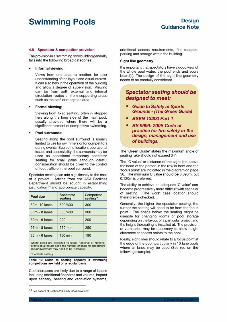
8/14/2019 Swimming Pools Design 2011 Rev3.pdf
http://slidepdf.com/reader/full/swimming-pools-design-2011-rev3pdf 56/97
Swimming Pools Design
Guidance Note
February Revision 003 55 © Sport England 2011
Spectator seating should bedesigned to meet:
Guide to Safety at Sports•
Grounds - (The Green Guide) BSEN 13200 Part 1•
BS 9999: 2008 Code of•
practice for fire safety in thedesign, management and use
of buildings.
44 See page 9 of Section 2.0 ‘Early Considerations’.
Pool sizeSpectatorseating
Competitorseating *
50m -10 lanes 500/600 300
50m - 8 lanes 350/400 300
50m - 6 lanes 200 200
25m - 8 lanes 250 min 250
25m - 6 lanes 150 min 180
Where pools are designed to stage Regional or Nationalevents on a regular basis the number of seats for spectatorsand/or swimmers may need to be i ncreased.
* Poolside seating
4.8 Spectator & competitor provision
The provision in a swimming pool building generallyfalls into the following broad categories:
Informal viewing:•
Views from one area to another, for userunderstanding of the layout and visual interest.It can also help in the operation of the buildingand allow a degree of supervision. Viewingcan be from both external and internalcirculation routes or from supporting areassuch as the café or reception area.
Formal viewing:•
Viewing from fixed seating, often in steppedtiers along the long side of the main pool,usually provided where there will be asignificant element of competitive swimming.
Pool surrounds:•
Seating along the pool surround is usuallylimited to use for swimmers or for competitorsduring events. Subject to location, operationalissues and accessibility, the surrounds may beused as occasional temporary spectatorseating for small galas although carefulconsideration should be given to the control
of foot traffic on the pool surround.Spectator seating can add significantly to the costof a project. Advice from the ASA FacilitiesDepartment should be sought in establishing justification 44 and appropriate capacity.
Table 10 Guide to seating capacity if swimmingcompetitions are held on a regular basis
Cost increases are likely due to a range of issuesincluding additional floor area and volume, impactupon sanitary, heating and ventilation systems,
additional access requirements, fire escapes,parking and storage within the building.
Sight line geometry
It is important that spectators have a good view ofthe whole pool water, the pool ends and scoreboard(s). The design of the sight line geometryneeds to be carefully considered.
The ‘Green Guide’ states the maximum angle ofseating rake should not exceed 34˚.
The ‘C value’ or distance of the sight line abovethe head of the person in the row in front and the
‘focus point’ are indicated in the diagram on page56. The minimum C value should be 0.090m, but0.120m is preferred.
The ability to achieve an adequate ‘C value’ canbecome progressively more difficult with each tierof seating. The worst case location shouldtherefore be checked.
Generally, the higher the spectator seating, thefurther the seating will need to be from the focuspoint. The space below the seating might beuseable for changing rooms or pool storagedepending on the layout of a particular project and
the height the seating is installed at. The provisionof vomitories may be necessary to allow heightclearance at access points to the pool.
Ideally, sight lines should relate to a focus point atthe edge of the pool, particularly in 10 lane poolswhere all lanes may be used (See red on thefollowing example).

8/14/2019 Swimming Pools Design 2011 Rev3.pdf
http://slidepdf.com/reader/full/swimming-pools-design-2011-rev3pdf 57/97
Swimming Pools Design
Guidance Note
February Revision 003 56 © Sport England 2011
C
R
D
N
T
T = Seating Row depth
N = Riser height
R = Vertical distance from focus point to eye
D = Horizontal distance from focus point to eye
C = ‘C’ Value
Focus point at water level -
preferred at pool edge (Red)
or if impossible at centre offirst swimming lane (Blue)
However, where this is not possible the sight linesshould be taken from a focus point located at the
centre of the first lane at water level (blue lines onthe following example).
Riser heights and seating row depths will generallybe a function of multiples of 0.28m minimumgoings and 0.19m maximum risers in order tocomply with BS 9999:2008 and the ‘Green Guide’for radial gangways.
Accessibility
Accessibility for wheelchair users needs to beconsidered early in the design. In very largefacilities wheelchair accessibility should bedistributed across the seating levels 45. Howeverfor smaller facilities, accessibility may only bepractical at pool side and/or the uppermost levelof the seating.
The position and height of wheelchair spacesshould also take into account the likelihood ofspectators standing in the rows in front, as shownin the above diagram.
Seating types
The type of seating will depend on use and scaleof the seating provision. Competitor pool side
seating is commonly a ceramic tiled ledge, possiblyheated for bather comfort.
Spectator seating for small pools may be formedfrom a simple continuous laminate slat usuallywithout a back rest, fixed to each concrete tier.
Intermediate spectator seating will generally be asfor small pools, but be provided with a fixedbackrest, or individual moulded plastic seat squabswith integral backrest, directly fixed to eachconcrete tier.
Larger pools will generally include individualspectator seats consisting of a coated metalsupport frame, fixed plastic back rest and tiltingseat squab, to allow easy access between rows. All framing materials should resist a pool hallenvironment.
Conflict with the need for privacy
There is a potential conflict between open viewsinto the pool water areas and the need for privacyfor certain sensitive user groups. The addition ofeasily operated blinds or other screening devicesshould be considered for all the glazing to the poolhall and or the learner pool.
Environmental conditions
See the building services Section 5.0 (page 57) forenvironmental conditions that should be createdfor formal spectator seating when located within apool hall enclosure.
Example of spectator seating design
45 Refer to ‘Accessible Sports Facilities’ design guidancenote available from the Sport England website.

8/14/2019 Swimming Pools Design 2011 Rev3.pdf
http://slidepdf.com/reader/full/swimming-pools-design-2011-rev3pdf 58/97
Swimming Pools Design
Guidance Note
February Revision 003 57 © Sport England 2011
5.0 Servicing the building
A safe, comfortable and attractive internalenvironment is essential in order to attract andsustain high levels of use. Good conditions arealso required for the lifeguards, teachers andspectators as well as achieving a reasonable lifeexpectancy from the building 46.
The engineering challenge in achieving thefunctional requirements in a sustainable manner issubstantial 47:
Large volumes of swimming pool water needs•to be kept warm and continually treated todeal with the pollution from bathers.
Air temperature, moisture content and air•quality in the pool hall need to be carefullycontrolled.
Issues include the containment and control of•a potentially corrosive atmosphere in theappropriate areas, internal acoustic conditions,and noise breakout to surrounding areas.
It is estimated 48 that the building servicesinstallation can account for between 35 and 50%of the capital costs of a modern pool. Theoperational sustainability is therefore critical.
The full pattern of use, operation and maintenanceregimes of the swimming pool should be allowedfor within the services design. The operator’srequirements should be obtained at an early stagein the design process.
Energy implications
Swimming pools use high levels of energy. It is
imperative that the building footprint is minimisedat the design stage and internal volumes carefullymodulated to give an appropriate feeling of spaceand airiness. The building fabric should also bewell insulated and effectively sealed from theoutside environment and any adjoining buildingelements.
Energy efficiency
At the initial planning stage a range of energy savingmeasures and the overall energy environmentalsustainability must be considered 49. In deciding themost appropriate strategy, whole life cost rather
than only capital costs should be assessed.
The plant requirementscan be considered in thefollowing groups:
Incoming services: Water,•
electricity, gas and meters
Pool water treatment•
system: Water filter(s)circulation pumps and pipework, chemical dosingequipments and backwashdisposal
Foul water disposal /•
drainage
Heating system: To heat•
the pool water, areas of the building and domesticwater supply including storage vessels and pressurisation systems
Energy / resource recovery•
equipment: Heatexchangers, CHP plant,water re-use
Air-handling plant: Heating•
and conditioning the pool hall air and associated spaces
Electrical distribution•
equipment
Water storage•
Movable floor and / or•
bulkhead systems.
46 The HSE book Managing Health and Safety in Swimming Pools
is a key reference.
47 CIBSE Guide G Public health engineering: Swimming pools.
48 Sports Council Guidance Note Swimming Pool - Building Services
Nov 1994.49 The UK national planning system has recently been amended to
make sustainability its underlying principle (PPS1).

8/14/2019 Swimming Pools Design 2011 Rev3.pdf
http://slidepdf.com/reader/full/swimming-pools-design-2011-rev3pdf 59/97
Swimming Pools Design
Guidance Note
February Revision 003 58 © Sport England 2011
Heating and ventilation will be one of the majorenergy loads for a pool, as even with moderncontrol systems it might need to operate for a highproportion of the time to avoid condensation.
Examples of energy efficiency and recoveryinstallations are:
Plate heat exchangers•
Run-around coils•
Thermal wheels•
Desiccant dehumidifiers•
Combined heat and power systems•
Pool covers•
Heat recovery from backwash•
Variable ventilation.•
Renewable energy
Renewable energy sources also need to beconsidered in order to help reduce carbonemissions and may be a requirement of a planningconsent. Examples include:
Passive design• 50
Solar photovoltaic cells (PV)•
Solar thermal panels•
Bio fuels•
Ground source heat pumps•
Ground source cooling•
Wind turbines.•
Water efficiency
Swimming pools use large amounts of waterthrough the backwashing of filters, constant freshwater make up (30 litres per swimmer), showersand cleaning. The feasibility of the following shouldbe considered:
Low water consumption taps and flushes for•toilets and urinals
Automatic shower controls•
Shower and backwash harvesting to flush•toilets
Rainwater harvesting•
Automated monitoring equipment for water•make up.
Pool water quality
The quality of the pool water is of criticalimportance, that will depend upon both the design,bather load and the ongoing operation. It is atechnically complex subject on which specificspecialist advice must be sought for each particular
project. The Pool Water Treatment Group (PWTAG)publication 2009 is regarded as the standard texton the subject.
The selection of the most appropriate type of watertreatment system for a swimming pool will dependon a number of factors:
Type and size of pool•
Bather load•
Characteristics of the source water supply•
Pool operation and maintenance.•
General power
5.5%
Space heating
53%
Water heating
25%
Fans and pumps
10%
Lighting 6.5%
Comply with relevant localenergy policies:
e.g. the Energy Hierarchy within
the London Plan
Use less energy - be lean•
Use renewable energy - be green•
Supply energy efficiently - be clean•
www.london.gov.uk/mayor/environment/energy/london_renew.jsp
50 Orientation and building form to maximise solar gain.
Typical energy profile for a swimming pool building

8/14/2019 Swimming Pools Design 2011 Rev3.pdf
http://slidepdf.com/reader/full/swimming-pools-design-2011-rev3pdf 60/97
Swimming Pools Design
Guidance Note
February Revision 003 59 © Sport England 2011
Pool type/bather load
Conventionaldisinfection
UV* O3*
Conventional/low 6
Conventional/medium 6 6
Leisure/high 6 6
*Residual disinfection is required in addition to preventcross infection in the pool.
*O3 = Ozone
Disinfection
A ‘conventional’ chlorine system has generallybeen considered to give an appropriate balance ofcapital costs, water and air quality, bather comfort,ease of control, maintenance and economy ofoperation. Sodium hypochlorite or calciumhypochlorite are commonly used to maintain a‘free chlorine level’ in the pool water to deal withthe pollution from bathers or other sources. Automatic control and dosing systems areregarded as essential to maintain safety, and giveobvious staffing and operational benefits.
However, water purification based on Ultra-Violet(UV) and to a lesser extent Ozone (O3 ) equipment
is commonly added into modern public poolinstallations. This involves additional equipmentwithin the plant room areas, to treat the circulatingwater and make subsequent disinfection easier.The benefits of such systems are:
Reduction in chlorine levels in the pool.•
Improved water quality – particularly where•high bather load is expected.
Improved air quality in the pool hall – through•reduction in airborne chloramines associatedwith red eyes, sore throats aggravation ofasthma and bronchitis, particularly beneficial
to asthma sufferers, pool staff and long termpool users.
However these systems can add significantly tothe capital and running costs of providing aconventional chemical only system. Both systemscan also require increased expertise from theoperator.
There are particular safety and technical issueswith all water treatment systems but as a generalguide the use of purification systems are as
follows:
Chemical dosing
Chlorine is used in the pool water to kill bacteriaand prevent cross infections between bathers. Themost common chlorine donors are:
Sodium Hypochlorite ( NaOCI)•
Calcium Hypochlorite ( Ca (OCI)2)•
These individually produce ‘free chlorine’ a chlorinecompound for disinfection, and ‘combinedchlorine’ when free chlorine is combined withpollutants - the cause of the typical chlorine smellin swimming pools.
It is necessary to control the acidity (pH) balanceof the treated water. For example, dilutedhydrochloric acid (HCI) is added when sodiumhypochlorite is used.
Using other chemical treatments should bediscussed in detail with the water treatmentengineer. In particular the use of SodiumBiSulphate (NaHSO4 ) should be avoided due to therisk of sulphate attack on cementitious grouts,renders and concrete. See the PWTAG publicationsfor more detail.
Pool water chemicals should always be dosed andmonitored by automatic equipment. Additional
manual testing of samples of water from the poolshould be undertaken regularly, at least twice aday as an additional check on the system.
Water softness
The use of calcium hypochlorite is often preferredin areas of ‘soft water’ since it is a calcium hardnessdonor to the pool. This will minimise the effects ofsoft water on cementitious materials used in thepool construction.
See the PWTAG 2009 publication for more moredetails and the appropriate design standards.
Ozone contact vessel and de-ozonising
Table 11

8/14/2019 Swimming Pools Design 2011 Rev3.pdf
http://slidepdf.com/reader/full/swimming-pools-design-2011-rev3pdf 61/97
Swimming Pools Design
Guidance Note
February Revision 003 60 © Sport England 2011
Filtration systems
An effective filtration system is required to maintainthe clarity of the swimming pool water. For publicpools sand filters are most commonly used. Inorder to maintain their effectiveness these willneed to be backwashed regularly. This is achievedby reversing the flow through the sand beds andthen discharging the backwash water to a fouldrain.
The discharge to the drains is classified as tradeeffluent and the consent may place restrictions onthe timing, volume and/or flow rate discharge perday. Backwash tanks to hold the back wash watermay be required to allow a controlled discharge tothe foul drainage system.
The overall hydraulics of the system, the rating ofpumps and the position of inlet and outlet grills inthe pool tank need to be carefully designed toensure contaminants are effectively removed fromthe water. Deck level systems are most effectivein removing contaminants from the watersurface.
To assist the filtration process chemicals known asflocculants are automatically added to the waterprior to it passing through the filters. Poly aluminiumchloride is most commonly used and it forms a
‘floc’ that helps trap fine particles, microbes andpollutants in the water.
UV filtration system
Turnover rates
The time for the total volume of pool water tocirculate through the treatment plant and return tothe pool is known as the turnover rate. The perioddepends on the shape size and use of the pool andshould be considered early in the design processas part of the water treatment system performancerequirements.
See the PWTAG 2009 publication for more detailsand the appropriate design standards
Typical filter installation
Pool TypeDepth(Metres)
Pool TurnoverRate (Hours)
Diving N/A 4 - 8
Swimming N/A 2.5 – 3
Leisure <0.5m 0.5
0.5 to 1.0 0.5 - 1
1.0 to 1.5 1 to 1.5
>1.5 2 to 2.5
Table 12 Recommended turnover rates
The risk of contamination
of the pool water can be minimised through:
Careful design and•
location of showers andtoilets
Good house keeping•
Bather education.•
(See showers and changing
room layout in Section 4.5)
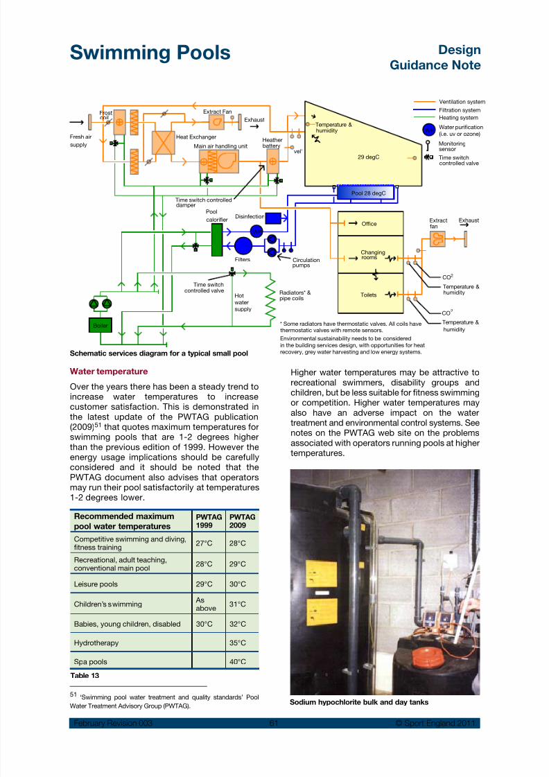
8/14/2019 Swimming Pools Design 2011 Rev3.pdf
http://slidepdf.com/reader/full/swimming-pools-design-2011-rev3pdf 62/97
Swimming Pools Design
Guidance Note
February Revision 003 61 © Sport England 2011
Extract Fan
Heat Exchanger
Main air handling unit
Frostcoil
Fresh airsupply
Exhaust
Heatherbattery
vel'
Temperature &humidity
Monitoringsensor
29 degC
Pool 28 degC
Office
Changingrooms
Toilets
Circulationpumps
DisinfectionPool
calorifier
Time switch controlleddamper
Time switchcontrolled valve
Filters
Boiler
Radiators* &pipe coils
* Some radiators have thermostatic valves. All coils havethermostatic valves with remote sensors.
Extractfan
Exhaust
CO2
Temperature &humidity
CO2
Temperature &
humidity
Pool 28 degC
Environmental sustainability needs to be considered
in the building services design, with opportunities for heat
recovery, grey water harvesting and low energy systems.
Ventilation system
Filtration system
Heating system
Water purification
(i.e. uv or ozone)
Time switchcontrolled valve
Hot
water
supply
WP
WP
Schematic services diagram for a typical small pool
Sodium hypochlorite bulk and day tanks
Water temperature
Over the years there has been a steady trend toincrease water temperatures to increase
customer satisfaction. This is demonstrated inthe latest update of the PWTAG publication(2009)51 that quotes maximum temperatures forswimming pools that are 1-2 degrees higherthan the previous edition of 1999. However theenergy usage implications should be carefullyconsidered and it should be noted that thePWTAG document also advises that operatorsmay run their pool satisfactorily at temperatures1-2 degrees lower.
Recommended maximum
pool water temperaturesPWTAG1999
PWTAG2009
Competitive swimming and diving,fitness training 27°C 28°C
Recreational, adult teaching,conventional main pool
28°C 29°C
Leisure pools 29°C 30°C
Children’s swimming Asabove
31°C
Babies, young children, disabled 30°C 32°C
Hydrotherapy 35°C
Spa pools 40°C
Higher water temperatures may be attractive torecreational swimmers, disability groups andchildren, but be less suitable for fitness swimmingor competition. Higher water temperatures mayalso have an adverse impact on the watertreatment and environmental control systems. Seenotes on the PWTAG web site on the problemsassociated with operators running pools at highertemperatures.
Table 13
51 ‘Swimming pool water treatment and quality standards’ Pool
Water Treatment Advisory Group (PWTAG).

8/14/2019 Swimming Pools Design 2011 Rev3.pdf
http://slidepdf.com/reader/full/swimming-pools-design-2011-rev3pdf 63/97
Swimming Pools Design
Guidance Note
February Revision 003 62 © Sport England 2011
Air temperatures and humidity
Pool hall
High temperature and humidity are required in thepool hall to maintain comfortable conditions forbathers. Air temperatures are usually kept at onedegree above the pool water temperature andrelative humidity and air velocity values asfollows:
Air temperature: approx 30°C•(assuming 29°C water temperature)
Relative humidity: 60% ± 10%•
Air velocity: Approx. 0.1m/s in the•
occupied areas of thepool hall
Min fresh air supply: 8-10 air changes/hour•
There should be even distribution and extractionof warm air from the pool hall so there are nodraughts on the pool surrounds or in the shallowend where people may be standing up.
The above conditions assume that the meanradiant temperature is approximately equal to orslightly higher than the air temperature. Theatmospheric conditions within an enclosed space
are never homogeneous and vary with time andlocation. They are particularly influenced by batheractivity.
Care should be taken that moisture and smellsfrom the pool hall cannot pass to adjoining areas.Effective moisture vapour barriers are required andgaps should be sealed to avoid potential damageto the building elements, particularly whereservices and ducts pass through walls. A negativepressure difference between the pool hall andadjoining areas such as changing areas can beused to help contain the pool environment.
See PWTAG 2009 for the importance of the
ventilation system in removing air born disinfectantby-products and contaminants from the pool halland ensuring an adequate distribution of fresh air.
Spectator area
Spectators in adjacent seating and viewing areaswill require a lower temperature created by anincreased fresh air supply as follows:
Air temperature: approx 25°C• 52
Relative humidity: 60% ± 10%•
Air velocity: approx 0.3m/s•
Min fresh air supply: 10 air changes/hour•
Additional comfort cooling systems may also beconsidered for spectators, but care should betaken to avoid cooler air dropping into bather areasand causing discomfort.
Changing and clothes storage areas
The airflow should be evenly distributed anddesigned to remove smells, particularly in changingareas and toilet areas. There should be nodraughts caused by airflow. In order to providecomfortable conditions as people change andmove back into the public areas the followingconditions should be provided:
Air temperature: approx 24-25º C•
Min fresh air supply: 10 air changes/hour•
This is often arranged as a separate system fromthat for the main pool hall. Some additionalcomfort cooling within the system could bebeneficial in vanity areas where people would intheir normal clothing.
Baby changing accommodation should haveseparate rates of ventilation.
Electrical services
Special care should be taken with electricalservices in view of the damp warm and corrosiveatmosphere 53. Mains voltage must not beaccessible within the pool hall.
Light fittings
See Section 4.3 general design issues for artificiallighting in the pool hall.
There are particular issues with underwaterlighting:
Size/type needs to suit the pool to be•
illuminatedReliability•
Expected lamp life/replacement cost•
Ease of re-lamping•
Water safety – no fitting should exceed 20V•operating current – need for transformerslocated relatively close to each fitting.
Where moveable floors are used, the underwaterlight fittings will need to be flush with the pool wall.
Some underwater light fittings may also suffer
from high temperatures at the glass lens, and in52 20°C is recommended for ancillary areas. Managing Health and
Safety in Swimming Pools.53 IEE guide and Electricity at work regulation1989.

8/14/2019 Swimming Pools Design 2011 Rev3.pdf
http://slidepdf.com/reader/full/swimming-pools-design-2011-rev3pdf 64/97
Swimming Pools Design
Guidance Note
February Revision 003 63 © Sport England 2011
order to avoid the risk of bather injury, theoperational temperature of the surface of the glassshould never become so hot as to be uncomfortableor dangerous.
Sizes of plant rooms
Plant rooms should be sized to give good accessto the equipment that they house and allow foroperation, maintenance, replacement anddeliveries.
Typically the pool water treatment plant roomshould be between 15-30%
54 of the water areathat it serves.
An economical solution is to locate the air-handlingplant at high level providing there is adequateaccess. A ‘rule of thumb’ to calculate the overallarea required is to allow approximately 15% of thepool building area.
Plant room spaces
The location, size and distribution of the plantwithin the building needs to be considered early inthe design process along with the operation andmaintenance factors.
The plant room spaces should:
Allow the plant and equipment to be installed,• commissioned, operated and maintainedsafely and efficiently.
Allow for service access and removal/ •replacement of all individual elements includingbulky items such as filters.
Minimise service runs, with water treatment•plant located close to the deep end of the pooltank.
Locate pool water circulation pumps at the•same level as the bottom of the deepest waterso that they are continually flooded.
Allow for the delivery and storage of chemicals•in a separate, ventilated area. Includeappropriate safety arrangements such as bundwalls for chemical storage tanks and dosingequipment and emergency drencher and eyewash facilities.
Ensure adequate ventilation rates to all plant•room areas. If ozone treatment is used,provide an automatic ozone detection alarmsystem and consider the need for similarsystems for chlorine and carbon dioxide.
Ensure adequate floor drainage in the plant•room and provide a hosepipe point.
Provide an accessible balance tank to•accommodate water displaced by bathers (fordeck level pools only). Access should be vialateral access ways from the plant room ratherthan manholes in the pool surround floor.
Provide holding tanks if required for the main•drainage system to deal with the quantity offilter backwashing water (can be separate fromplant room).
Allow space for new technology such as housings•for underwater camera control panels.
Provide adequate space for a workbench,•desk and chair, tools, maintenance manualsand so on.
Ensure flues, air intakes, ventilation and extract•louvers/cowls are positioned away from publicand residential areas.
Ensure safe access to all plant/equipment•requiring regular inspection.
Allow for control equipment and underwater•pool windows associated with computerassisted underwater pool supervision.
Plant rooms should be connected to all•emergency alarms.
Access to plant rooms
Access to the plant room should be available bothinternally via a controlled access point andexternally via delivery entrance. All doors leadingto the plant room must have secure lockingmechanisms fitted to prevent access by untrainedstaff and members of the public.
If an external service yard is provided, the externalaccess should incorporate the provision of a steelshutter door system. The door should be fitted
with a high security locking system and beconnected to the centre’s security alarm. The idealopening size is 3.0m wide by 2.5m high. Thereshould also be an additional side door for externalaccess to the plant room to reduce wear and tearon the steel shutter and the probability of it beingleft open during a period of frequent use.
Doors in the plant room should be of a heavy dutynature and have a minimum opening width of 1.0m(1.5 m preferred).
Air distribution systems in the pool hall
There is a marked move away from supplying air
through overhead ducted systems to the use ofducts incorporated at low level into the pool tankdesign. These systems either sit adjacent to the
54 PWTAG / Sports Council Guidance Note : Swimming pools
Building Services.

8/14/2019 Swimming Pools Design 2011 Rev3.pdf
http://slidepdf.com/reader/full/swimming-pools-design-2011-rev3pdf 65/97
Swimming Pools Design
Guidance Note
February Revision 003 64 © Sport England 2011
pool water overflow system or are set at low levelaround the perimeter of the pool hall. If locatedunder glazed curtain walling they have theadditional benefit of reducing the condensationthat can form on the windows.
The low level systems do have drawbacks – poorlydesigned systems can become flooded if the poolwater spills over the pool deck surround or fromground water. If no drainage system is incorporatedinto the air duct then, at worst extensive damageto the air handling plant ensues, at best the floodwater is very difficult to remove.
Over head ducting is still specified in some pooldesigns and as with direct lighting units it canprove difficult to avoid positioning directly overwater and maintenance becomes veryproblematic.
The ductwork fixings must be carefully selected asthere have been several cases of ducting sectionsfalling from height due to corrosion and subsequentfailure of the fixings studs etc. Regular inspectionof all ventilation ductwork and fixing must takeplace. This requires suitable access.

8/14/2019 Swimming Pools Design 2011 Rev3.pdf
http://slidepdf.com/reader/full/swimming-pools-design-2011-rev3pdf 66/97
Swimming Pools Design
Guidance Note
February Revision 003 65 © Sport England 2011
6.0 Constructing the building
The need to pay particular attention to the detailedconstruction specification for swimming pools canscarcely be overstated. The building mustwithstand a warm, humid and aggressive internalenvironment and external temperatures expectedin the winter season. This can be a highly technical,complicated and demanding subject, requiring theservices of specialist consultants. Key factorsinclude:
Heavy wear and tear and possible abuse•during use.
Avoidance of interstitial and surface•
condensation that can lead to corrosion/rotand failure of various elements - particularlythose concealed within the structure.
Ease of maintenance to ensure a clean and•hygienic environment that eliminates dust, dirtand water traps.
The creation of safe conditions for users.•
The following notes are intended to illustrate therange of potential problem areas and point to theneed to ensure experienced professional expertiseis available in all areas of the project team and thatdue account is taken of current research and
recommendations.
Types of pool tank design
The pool tank and the pool surround need to bedesigned as water retaining structures. There aretwo main types:
Concrete pool tanks
These would normally be constructed fromshuttered in-situ reinforced concrete to BS 8007.They can be formed with or without a screed / render and normally have a ceramic tile finish.
Waterproofing additives can be used to reduce therisk of leakage. The tank structure should bethoroughly tested for water tightness, through afull depth tank test before finishes are applied. Anyfaults should be remedied after allowing the pooltank to dry out thoroughly, and before tiling orlining work is undertaken. Any repair is moreeffective from the wet side.
Pre-cast concrete panels should generally beavoided due to problems of guaranteeing watertightness at the joints. Permanent shutteringshould also be avoided due to risks of deteriorationif leakage does occur over the life of the pool tank
or problems identifying any leakage path forrepair.
Structural movement joints in the pool tank shouldbe avoided where possible. Joints between thetank and the pool surround should also beminimised where possible. If joints are unavoidable,these must have an effective proprietary water barsystem suitable for their application.
Pool surrounds should be designed to the samestandard as the pool tank, and provision made toprevent lateral water travel to other areas.
Other concrete pool construction forms include
sprayed concrete (gunnite) and concrete blockworkformwork filled with reinforced concrete. Theseforms are primarily associated with private andhotel pools, and there are considerations in respectof their use in larger pools that will require verycareful attention. Expert independent adviceshould be sought before considering these formsof pool construction.
The use of tanking membranes in the poolsurrounds, as an alternative to water retainingconcrete should generally be avoided. However iftanking is unavoidable great care must be taken inthe selection, detailing and testing of the
membrane. The risk of damage due to thermalshock when the pool is emptied or filled with waterand heated is a critical issue. This must be takeninto account and integrated into the design,construction and operation of the building asfollows:
Activity Rate 55
Max fill/empty rate 0.03m/hour (0.75m/day)
Max heat ing rate 0.25°C/hour (6°C/day)
Table 14
Materials – should be selected with regard totheir environmental
sustainability, whilst alsoensuring durability and
lifecycle qualities:
Recyclable content •
BRE green guide rating•
Environmental profile.•
55 BS5385: Part 4: 2009 Wall and floor tiling – Part 4: Design and
installation of ceramic and mosaic tiling in special conditions – Code
of practice.

8/14/2019 Swimming Pools Design 2011 Rev3.pdf
http://slidepdf.com/reader/full/swimming-pools-design-2011-rev3pdf 67/97
Swimming Pools Design
Guidance Note
February Revision 003 66 © Sport England 2011
Stainless steel pool tanks
Prefabricated sectional stainless steel tankstructures are becoming more common, althoughin the UK these are still an emergent market. Theyare supported on a concrete slab and are eithersite welded to form a complete tank structure orare bolted together. A welded reinforced plasticliner may also be used for the walls and/or floor ofthe tank.
Advantages of the stainless steel pool:
Quicker to assemble and install (but will require•an extensive period for design and offsitefabrication).
Elimination of issues associated with a•conventional concrete pool tank.
Finished quality and dimensional tolerances of•the tank can be more closely controlled.
Tank under construction in stainless steel panels withan integrated overflow and raised end
Issues to be carefully considered as part of thesystem selection and design process include:
The need for independent structures for the•steel pool tank support framework and poolsurround retaining walls, allowing periodicchecks for potential leaks and degradation.
Selection of the support structure and panel•materials and their fixings to avoid or minimisethe risk of corrosion.
Establish that the pool system will last the•intended design life of the building. A cost inuse appraisal for the proposed life of thebuilding is recommended.
Provision of a watertight joint at the junction•between the steel tank and the pool surroundneeds careful consideration. The poolperimeter details are critical: a tanked poolsurround may be required, and the interface ofthe pool and surround needs careful detailingin order to avoid leakage. Where pool linersare used, the pool wall panel liner should befully bonded to the metal panel.
Fixed pool equipment: As discussed in section•4.4 the pool surrounds require a number offixing points for temporary equipmentassociated with the various elements of the
swimming progamme. Refer to section 6.0 fordetails.
The length of manufacturer’s guarantees for•the polymer liner and the risk of mechanicaldamage.

8/14/2019 Swimming Pools Design 2011 Rev3.pdf
http://slidepdf.com/reader/full/swimming-pools-design-2011-rev3pdf 68/97
Swimming Pools Design
Guidance Note
February Revision 003 67 © Sport England 2011
Pool tank constructions
A comparison of the essentia l key differences (assuming other factors can be treated as equal)
Concrete Stainless Steel
Structural Option 1:
Monolithic design for whole of tank and•pool surrounds when constructed frominsitu water retaining concrete to BS8007/ BS EN 1992 Part 3 gives a highlystable structure
Option 1:
Stainless steel side walls incorporating•structural back framing fixed to areinforced concrete floor
Option 2: 56
Gunnite sprayed reinforced concrete•
Reinforced concrete block work with•waterproof renders /coatings
An Integral transfer channel is the mostcommon option
Fixtures and fittings need to be integratedinto the tank design
Option 2:
Polished stainless steel side walls and•
floors incorporating structural backframing and welded seams
Stainless steel wall panels are generallyavailable up to 3m depth only – deeperpools will need a composite wall ofconcrete (lower) and stainless steel(upper)
An integral stainless steel transferchannel can be part of these systems
Some fixtures and fitting can beintegrated into an integrated transferchannel
Junction with pool surrounds and floorstructure need special care
Waterproofing Inherent within well constructed insitu•reinforced concrete pools meeting BS8007/ BS EN 1992 Part 3
Can be augmented by waterproof liner•and/or render
Option 1
Factory bonded PVC faced galvanised•or stainless steel wall panels and loosePVC floor liner with all seams thermallywelded
Option 2
Bare polished stainless steel wall and•floor panels with welded panel joints
Option 3
Structure as option 1 with loose fitted•PVC water proof pool liner withthermally welded seams
Finishes Option 1
Fully ceramic tiles on render backing is•the preferred finish
Option 1
PVC factory applied finish to wall panels•and loose PVC liner sheet to floor
Option 2
Specialist finish renders and paint•finishes have been used where long termdurability is not so important
Option 2
Ceramic tile option to upper wall sections•subject to design and stiffening
Option 3
Loose PVC liner•56 Gunnite and reinforced concrete construction are more commonly used for private /hotel/fitness centre pools and are unlikely to achieve thelong term life of an in-situ RC pool.
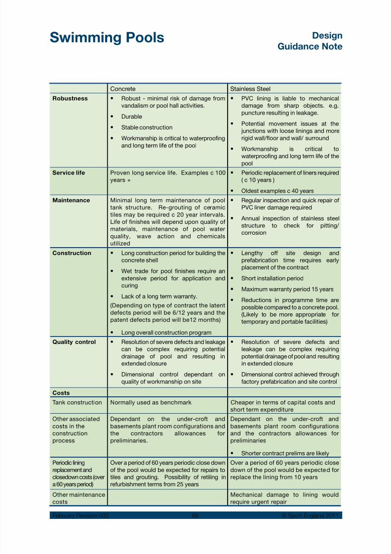
8/14/2019 Swimming Pools Design 2011 Rev3.pdf
http://slidepdf.com/reader/full/swimming-pools-design-2011-rev3pdf 69/97
Swimming Pools Design
Guidance Note
February Revision 003 68 © Sport England 2011
Concrete Stainless Steel
Robustness Robust - minimal risk of damage from•vandalism or pool hall activities.
Durable•
Stable construction•
Workmanship is critical to waterproofing•and long term life of the pool
PVC lining is liable to mechanical•damage from sharp objects. e.g.puncture resulting in leakage.
Potential movement issues at the• junctions with loose linings and morerigid wall/floor and wall/ surround
Workmanship is critical to•waterproofing and long term life of thepool
Service life Proven long service life. Examples c 100years +
Periodic replacement of liners required•( c 10 years )
Oldest examples c 40 years•
Maintenance Minimal long term maintenance of pooltank structure. Re-grouting of ceramictiles may be required c 20 year intervals.Life of finishes will depend upon quality ofmaterials, maintenance of pool waterquality, wave action and chemicalsutilized
Regular inspection and quick repair of•PVC liner damage required
Annual inspection of stainless steel•structure to check for pitting/ corrosion
Construction Long construction period for building the•concrete shell
Wet trade for pool finishes require an•extensive period for application andcuring
Lack of a long term warranty.•
(Depending on type of contract the latentdefects period will be 6/12 years and thepatent defects period will be12 months)
Long overall construction program•
Lengthy off site design and•prefabrication time requires earlyplacement of the contract
Short installation period•
Maximum warranty period 15 years•Reductions in programme time are•possible compared to a concrete pool.(Likely to be more appropriate fortemporary and portable facilities)
Quality control Resolution of severe defects and leakage•can be complex requiring potentialdrainage of pool and resulting inextended closure
Dimensional control dependant on•quality of workmanship on site
Resolution of severe defects and•leakage can be complex requiringpotential drainage of pool and resultingin extended closure
Dimensional control achieved through•factory prefabrication and site control
Costs
Tank construction Normally used as benchmark Cheaper in terms of capital costs andshort term expenditure
Other associatedcosts in theconstructionprocess
Dependant on the under-croft andbasements plant room configurations andthe contractors allowances forpreliminaries.
Dependant on the under-croft andbasements plant room configurationsand the contractors allowances forpreliminaries
Shorter contract prelims are likely•
Periodic liningreplacement andclosedown costs (over
a 60 years period)
Over a period of 60 years periodic close downof the pool would be expected for repairs totiles and grouting. Possibility of retiling in
refurbishment terms from 25 years
Over a period of 60 years periodic closedown of the pool would be expected forreplace the lining from 10 years
Other maintenancecosts
Mechanical damage to lining wouldrequire urgent repair

8/14/2019 Swimming Pools Design 2011 Rev3.pdf
http://slidepdf.com/reader/full/swimming-pools-design-2011-rev3pdf 70/97
Swimming Pools Design
Guidance Note
February Revision 003 69 © Sport England 2011
Pool edge details
The pool edge detail can be formed with proprietarysolid, pre-cast ceramic units, or cast as part of theconcrete pool edge profile, where the deck levelchannel is set back away from the pool edge. Inboth cases the channels are covered with a slottedplastic grille. The following are important factorsregarding finishes to a pool:
An appropriate surface treatment to concrete•pool tanks is required to provide a key forapplied finishes. This is usually achievedthrough mechanical keying the concretesurface to expose the coarse aggregate.
Compatibility of the tiling specification with the•tile adhesive and grouting.
Soft water, aggressive chemicals, rapidly•moving water or heavy wear may require tilingto receive epoxy based adhesives and/or
grouts in lieu of cementitious based ones.
However for cost, application and programmereasons, the use of epoxy grouts should beminimised.
Waterproof membranes should generally not•be used between pool tiling and a concrete
pool structure, as these can be the cause ofsubsequent failure of the finishes if there is anyshocking of the tank during emptying orheating of the pool. The pool tank should bedesigned to be waterproof.
The noise of the circulating water continuously•falling into the deck level channel can bedistracting. In order to minimise the impact ofwater flow, the pool side of the deck levelchannel should be set at an angle so that thewater runs down the channel side face ratherthan tumbles into the channel. See SectionB-B overleaf.
Typical low voltage recessed underwater light fitting
6 5 4 m m
Pool underwater
light fitting should be
selected on lamp life
ease of re-lamping and
cost in addition to any
performance criteria.
Deck level channel. Pool Surround Foul Drain
Note:
Refer to page 80 for further
information regarding drainageof pool surrounds.

8/14/2019 Swimming Pools Design 2011 Rev3.pdf
http://slidepdf.com/reader/full/swimming-pools-design-2011-rev3pdf 71/97
Swimming Pools Design
Guidance Note
February Revision 003 70 © Sport England 2011
B
B
B
B
A A
A A
i i i l li i l i
i i i i l i i i i ill l
i i l i i i i
i i i l i
l i l l i l l
i li i l ili i i l i i
l i i l l i i
l i
B
B
CC
CC
B
B
Note: The Weisbaden pool edge detail is unlikely to
be suitable for larger pools due to the limited capacity
of the channel. Advice should be obtained from the
services consultant before selecting this detail.
Example plan of a general purpose swimming
pool showing deck level edge channel
provided to the perimeter of the pool tank.
For competition use removable turning
boards and starting platform can be used
Example plan of a competition pool with
permanent raised pool ends with deck
level edge channels provided along the
sides of the pool tank
Note: Rake to front face of channel to reduce water
generated noise. Twin channels built into pool surround -
one to take pool water return to filtration the other to
provide independent drainage of the pool surround to
prevent poluted water entering the pool.
Section B - B - Alternative example
of deck level edge channel (’Weisbaden’
ceramic channel).
Section B - B - Example of deck level
twin edge channel (Builders work)
3
525mm min
300
Section A - A - Alternative example of raised end with
integrated ceramic filtration ‘scum’ channel providing
a finger grip at water level
Separate pool surround
foul drainage
Section A - A - Example of builders work raised end excluding
filtration channel and with finger grip provided at top
Note: The provision of permament raised ends should be limited to poo ls where extensive
competitive use is an essential requirement. Lifeguard supervision will also need to
take account of any additional risks the provision of raised ends may present to bathers .
Note: For inexperienced swimmers the channel may present a hazard during
tumble turns. For poor swimmers and older people however, particularly
those with limited shoulder mobility taking part in length swimming, the
channel is of considerable help and gives confidence to swimmers.
Note: rake to front face of channel to reduce water generated noise.
i l il i li l
i l l l li i i
l i l ii l l i i il
l
i i l il i l
l l i
i i i l
l i l
Section C - C - Example of deck level pool end with twin edge
channel and removable starting platform with integral turningboards (if required - bolted to pool surround)
300
Starting platform
Separate pool surround
foul drainage
870
Examples of pool edge details

8/14/2019 Swimming Pools Design 2011 Rev3.pdf
http://slidepdf.com/reader/full/swimming-pools-design-2011-rev3pdf 72/97
Swimming Pools Design
Guidance Note
February Revision 003 71 © Sport England 2011
Finish tolerances
Floors generally < 0.005m *
Floors laid to falls < 0.003m *
Finished tile level of leadingedge of deck level pool channelconsistent datum level
0.000m *
* The greatest distance between the straightedge and
the tile surface measuring over a distance of 3m.
Table 15
Points to consider:
Permanent raised ends•
help to prevent swimmers
misjudging the end of the
pool and avoid the need for
turning boards for
competitions
A drainage channel is still•
required to drain the pool
surround behind the raised
ends if the surrounds fall
towards the pool edge
A hand hold is required •
Fixings for lane lines,•
starting platforms, turn
boards (if no raised ends),
touch panels and
automatic timingequipment.
Finishes to wet areas
Tiling to all wet areas should be laid to a fall. Agradient of 1:40 is generally adopted, but shouldnot be steeper than 1:35 or flatter than 1:55 forsafety and proper drainage.
A consistent datum level around the deck levelchannels is particularly important to ensure aconsistent flow of water over the weir and theproper functioning of the deck water circulation
system. Structural movement joints must becoordinated with tile joints, and sealants must beselected on their suitability for use in a pool.
Stress relieving joints in the tiling must also becarefully considered. BS 5385 Part 4 recommendsstress relief joints at all changes of direction andevery 6m where tile grout joints are less than 5mmwide. However, for the purposes of good practicestress relief joints should be considered in any poolregardless of joint size.
The selection of slip resistant tiles can be complexin the UK. The majority of ceramic tiles are testedfor slip resistance under the German DINStandards, DIN 51097 (bare foot) and DIN 51130(shot foot) 57 both of which are excellent forestablishing a tile’s inherent slip performance.However these are tests undertaken in a laboratory,and it is not possible to assess tile performanceonce installed.
In the UK the HSE pendulum and micro-roughnesstests 58 are increasingly used to establish insitu slipperformance. This is mainly due to the HSE slipresistance test being portable and is being used inlegal injury compensation cases.
Slip resistance tests can be influenced by a numberof factors, including surface profile, extent of tile joints in addition to any inherent slip resistantproperties of the tile. Also, slip resistance candegenerate due to poor care during constructionor poor cleaning techniques during use.
It may be necessary for the tiles to be additionallytested at specification, post-installation and duringuse to enable comparison in actual performance.
The primary benefit of the HSE tests are that theycan be undertaken to test a particular tile insitu, toenable a comparison of the tile’s performance andassist in identifying the potential cause of any slipproblem as supplied, installed or maintained.
Generally, bare foot only trafficked areas such asthe pool surround should have the highest gradeof slip resistance. These would include poolsurrounds, flume towers, showers, shallow water
areas (less than 1.35m) where the buoyancy is lowand anywhere where barefoot users might betempted to run. In other areas where barefoot andshod foot traffic is shared the ability to easily cleanand maintain the tiles also needs to beconsidered.
Note: The slip resistance requirements of tiling inthe pool tank is specified in BSEN 15288-1:2008.
57 HSE Technical Information Sheet ‘Assessing the Slip Resistance
of Flooring.
58 See Appendix 2 and BSEN 15288: Part 1: 2008 Swimming Pools:
Safety requirements for design.

8/14/2019 Swimming Pools Design 2011 Rev3.pdf
http://slidepdf.com/reader/full/swimming-pools-design-2011-rev3pdf 73/97
Swimming Pools Design
Guidance Note
February Revision 003 72 © Sport England 2011
When selecting tiles avoid selecting on the basisof marginal passes in tests, as construction anduse will inevitably allow some degradation inperformance.
A mid tone colour is usually considered mostpractical for keeping a clean appearance. Avoidwhite and dark colours on pool surrounds or anyheavily trafficked areas as these can show stainsand are difficult to clean.
Structural frame
The structural spans involved in a swimming pooldesign usually involve a framed structure. Steel ortimber laminated beams and columns arecommonly used. However, load bearing masonryand steel or timber beams can be a feasiblesolution on small projects.
The protection of the structure from corrosion and/ or rot is of the utmost importance, particularly asthe material’s strength and stability can also beimpaired. For example, some adhesives inlaminated timber can be adversely affected by thepool atmosphere and steelwork can be badlycorroded when concealed within the wallconstruction.
Steel work must be protected with an elaborateproprietary paint system that involves specifiedthicknesses of zinc rich paints that are often epoxyor polyurethane based. All protective coatings
should be carefully discussed with the specialistcoating company and be based upon intendeduse, expected environment, exposure and a life tofirst maintenance, normally not less than 10 – 15years.
Roof structures will need to support:
Suspended services such as ventilation ducts•and light fittings
Equipment such as safety harnesses in diving•pools.
Tile manufacturers should be asked to provide slip resistance test data in accordance with HSE guidance in addition to DIN standard test data.
Roof enclosure
Critical factors are the avoidance of interstitial andsurface condensation and material corrosion. Keydesign checks should assess condensation risk,vapour resistance gradient, thermal insulationgradient, and ventilation.
The roof construction/ceiling finish should bedesigned to:
Provide high levels of insulation and to prevent•condensation
Be resistant to the pool environment•
Provide sound absorption•
Have no effect on the colour of the pool water•
Withstand ball impact if the pool is used for•water polo
Provide a good surface reflector for the spread•of light.
A number of proprietary systems are available thatare a composite of an outer weathering sheet,insulation, a vapour barrier and aluminium innerlining sheet. They can eliminate internal voids anduse the self finish lining layer as a vapour barrier.However, other factors such as the need for fixings
for an acoustic underlining need to beconsidered.
Roof-lights should be of the double glazed diffusingtype, not more than 25% (approximately) of thetotal roof area.
Where suspended ceilings are considered, it isimportant that the space is not subject to a risk ofcondensation. This can be done by designing theroof structure as a ‘warm roof’. Care must be takento avoid piercing vapour barriers with fixings. Forceiling hangers or suspended services protectedfixing systems are available to hold the roof to thestructure.
External walls
The principles of design to avoid cold bridging andavoiding interstitial condensation in the roof applyequally to the walls.
External walls should be constructed to:
Provide high levels of insulation•
Withstand damage from vandalism•
Provide an attractive, durable, low maintenance•finish
Allow for structural movement as required by•the structural engineer
Be resistant to the pool environment.•

8/14/2019 Swimming Pools Design 2011 Rev3.pdf
http://slidepdf.com/reader/full/swimming-pools-design-2011-rev3pdf 74/97
Swimming Pools Design
Guidance Note
February Revision 003 73 © Sport England 2011
Masonry and metal cladding systems as externalmaterials are very common. Increasingly commonis timber cladding, which should be designed inaccordance with the TRADA publication ‘ExternalTimber Cladding’.
The Building Regulations New AD Part L requireshigher levels of insulation and special considerationshould be given to thermal bridging, vapourbarriers and dew point control due to enhancedrisk of condensation.
Internal skins of external walls should preferablybe of masonry or concrete block work (with orwithout applied finishes).
Lightweight structural framed systems are beingused for some conventional construction projects,but due to the aggressive pool environment(including condensation and corrosion risks)specialist advice must be sought beforeconsidering as this may impact upon the building’sexpected life.
Gypsum walling products (e.g. plasterboard)should be avoided.
Glazing
Glazing will need to be double or triple glazed.Large areas of glass can cause cold radiation
which can be reduced by local ventilation orelectrically heated glass (expensive). High thermalperformance glass may be a requirement to meetcurrent Building Regulations 59, particularly forlarge glazed elements.
Where areas of thermally insulated glazing areused, particularly if including solar control glass,thermal shading coefficient checks should bemade.
Glazing adjacent to the pool surrounds must beable to resist body impact and if the pool is toaccommodate water polo - ball impact. Refer toBS6262 and BS 6399: Part 1. The risk of injury ifglass is broken should be given carefulconsideration in all barefoot areas. In addition,glass when immersed can be very difficult to see,therefore glass should be laminated. Considertoughening glass prior to lamination for maximumsafety.
For resistance against rot, glazed assemblies arecommonly aluminium proprietary framed units witha powder coated finish and integral thermalbreak.
59 Building Regulations Approved Document Part L.
Where the glazing is formed using structuralglazing e.g. planar type systems, great care mustbe taken in respect of material use – stainless steelglass support fittings in particular needconsideration due to corrosion risks.
If timber windows are to be used, select from aproprietary range with known performance inpools. Important considerations include:
Timber species & grade•
Method of rot protection•
Finish•
Exposure rating•
Structural requirements•
Fire requirements•
Life to first maintenance.•
Roof lights – There are a wide range of rooflightmaterials that are suited for use in a poolenvironment. The primary considerations for theirselection should be:
Structural requirements – span and impact•upon the primary roof structure – particularlyvaults or stressed skin systems (e.g. inflatedETFE – Ethyl-tetra-fluoro-ethylene) where
lateral tension or compressive loads can betransferred.
Resistance to corrosion – selection of materials•and finishes.
Condensation through framework – need for•a thermally broken system, or through theglazing – avoid glazing with separate skinmultiple units where condensation can becometrapped between the glazed skins.
Curtain walling – in addition to the requirementsfor glazing above, large areas of curtain walling will
require a secondary support structure, normally ofsteel hollow section or possibly laminated timber,attached back to main structural frame members.Steel secondary framework will need similarcorrosion protection as the main structure anddissimilar materials must be isolated to minimizerisk of galvanic action resulting in corrosion ofmetals in contact with each other.
Glass balustrades are a common feature inswimming pool facilities that provide spectatorviewing to the pool area. However, the glass mustbe designed to BS6262 and BS 6399: Part 1.Structural supports must be designed to obviate
the risk of corrosion and bare stainless steel shouldbe avoided (see page 76).

8/14/2019 Swimming Pools Design 2011 Rev3.pdf
http://slidepdf.com/reader/full/swimming-pools-design-2011-rev3pdf 75/97
Swimming Pools Design
Guidance Note
February Revision 003 74 © Sport England 2011
Internal walls
The internal construction / finish should:
Withstand body impact and ball impact if the•pool is used for water polo.
Prevent water penetration at low level from•regular hosing down of pool surrounds.
Allow for structural movement as required by•the structural engineer.
Resist staining and absorption of body fats.•
Have no effect on the colour of the pool•water.
Provide sound absorption above 2m from pool• surround level.
Be capable of supporting loads, including•services, pool cover, bench seating, includingthe loading of person(s) standing on them.
Avoid use of ‘stud’ partitions – particularly•those with gypsum wallboard products. Wherestudwork is unavoidable ensure all frameworkis of galvanised steel, further coated in severelocations – not timber and select wall boardssuitable for constant wetting withoutdeformation, absorption or degradation. Avoiduse where fittings are to be fixed to the wall.
Provide horizontal dpc’s at top of skirting level•to prevent rising damp into the wall.
Movable floors and bulkheads
The movable floor/bulkhead design, constructionand installation should:
Comply with the recommendations of BS EN•13451; Part 11 and the HSE publication HSG179 - Managing Health & Safety in SwimmingPools’ section Physical Environment.
Allow for easy movement of the floor/bulkhead.•
Not interfere with or compromise in any way•the circulation of the water in the pool.
Bulkheads that are part of a deck level surroundshould have a black line to denote the edge.
Bulkheads that are used to separate pools ofdifferent depths or are used for access byswimming officials during an event should haveportable stainless steel hand or barrier rails and ahandhold at water level.
The floor/bulkhead manufacturer should provide
detailed information regarding installationrequirements and accuracy of the pool tanknecessary for their proper operation.
Fixed pool equipment
For competition use a pool will require a range offittings and equipment. (See also Section 4.7):
Automatic officiating system (timing) including•timing pads, electronic interface to specialstarting platforms, connections for startingwith both audible and visual signals andcomputer interface for scoring
Electronic scoring board(s), timing clocks•
Starting platforms and (for pools without•permanent raised ends) turning boards
Lane ropes•
False start rope posts•
Water polo goals•
Back stroke warning flags and posts•
Diving boards (spring boards and platforms).•
The officiating equipment and score boards canbe temporary or permanent systems dependingupon use. For regular use a system includingpermanent wiring and ducts should be considered.Specialist advice should be sought at an earlystage to identify builder’s work needed to beincorporated. The selected system should meet
ASA/FINA requirements.
Diving boards will need to comply with the ASA/ FINA requirements. Springboards are generallyrequired of an approved type and manufacturer.(See also section 4.4).
The remainder of the equipment noted above isnormally mirror polished grade 316 stainless steeland re-movable, but would require stainless steelpermanent sockets to be fitted into the pool andpool surrounds. Examples of these are shown onthe following diagram. These are normally coredrilled into the finished floor/wall and set in epoxide
grout rather than cast-in, in order to achieveaccuracy of placement. However the poolstructure will need to be designed to accommodatethe fittings without undermining any water proofingand the sockets may in some cases need to resistpull-out loads.
BS EN 13451 Parts 1 to 11 inclusive covers thesafety requirements for items of all equipmentused in a swimming pool. Refer to Appendix 2 fora complete list of the various parts.

8/14/2019 Swimming Pools Design 2011 Rev3.pdf
http://slidepdf.com/reader/full/swimming-pools-design-2011-rev3pdf 76/97
Swimming Pools Design
Guidance Note
February Revision 003 75 © Sport England 2011
Fixed Pool Equipment
1 5 0 m i n
38mm diameter
stainless steel
cylindrical socket
Stainless steel
cap seals socket
when equipment
removed
1 5 0 m i n
48mm polished
stainless steel
removable tubular
rail
Platform secured by stainless
steel bolt screwed into socketStainless steel bolt
seals socket when
equipment removed
7 5 m i n
1 5 0
Support bracket
bolted into
socket
1 5 0
Lane rope attaches
to removable stainless
steel eye bolt fixed
into socket
Stainless steel
socket with
integral cover
plate resin
anchored into
pocket cast in
or core drilled
into concrete
Stainlesssteel tube
drops into
socket
‘E’ type socket - turning boards
‘D’ type socket - False start/backstroke warning poles
‘B’ type socket - Pool entry step handrails
Stainless steel socket
resin anchored into
pocket cast in or core
drilled into concrete
‘A’ type socket - Lane Ropes
(Deck Level Detail)
150
Lane rope
attaches to
stainless steel
eye bolt fixed
into socket
Stainless steel socket
resin anchored into
pocket cast in or core
drilled into concrete
Stainless steel
socket resin
anchored into
pocket cast in
or core drilled
into concrete
5m
5m
10m
5m
Lane ropes at 2m centres0.5m 0.5m
Back stroke warning flag line
Back stroke warning flag line
False start recall line
C/ E
B
D
D
D
A
Location of equipment
Start ing platforms
Pool equipment locations and fixing details for a 25m x
6 lane swimming pool
Stainless steel
socket resin
anchored into
pocket cast in
or core drilled
into concrete
‘C’ type socket - Starting platform
‘A’ type socket - Lane Ropes
(Freeboard Detail)

8/14/2019 Swimming Pools Design 2011 Rev3.pdf
http://slidepdf.com/reader/full/swimming-pools-design-2011-rev3pdf 77/97
Swimming Pools Design
Guidance Note
February Revision 003 76 © Sport England 2011
Stainless steel in the pool hall environment
Stainless steel is not corrosion proof and needsspecial consideration for swimming poolapplications. There has been a marked increasein premature failures of the material in recent yearsthat has been linked to the way swimming poolsare being constructed and used. This includes:
Higher pool water operating temperatures at•(30
oC+) and thermal gain through glazing that
creates air temperatures that are considerablyhigher.
Pool features such as flumes and water sprays•increase levels of water vapour and chloramine
pollutants in the atmosphere.Increased use of stainless steel in highly•stressed structures – particularly undertension.
Inadequate control of ventilation and moisture•content.
Increased use of cold formed stainless steel•components – or mixture of cold and hotformed materials in components such asbolts.
These conditions cause degradation of thepassivating layer stainless steel normally producesto protect itself from corrosion. If left uncheckedpitting and crevice corrosion quickly occur. Thiscan lead to stress corrosion cracking (SCC) andpremature failure of components.
This can be particularly serious if stainless steelcomponents are used for structural support – suchas roof trusses and ventilation ductwork.
If stainless steel is essential in structural situationsavoid details in which key components are underhigh stress 60. Avoid bare stainless steelcomponents and consider a protective coating.
Operators should instigate a regular inspectionroutine and put in place maintenance practices tomake good any visible corrosion before it becomesserious.
Only use bare stainless•
steel in situationswithin the pool splash
zone and where it can be easily and regularlycleaned and inspected.
Consider grade of•
stainless steel andfinish to minimise
maintenance and riskof corrosion.
Consult with the Nickel•
Development Institute(NiDI) and the BritishStainless Steel
Association (BSSA) regarding ideal gradefor each application.
In other situations,•
stainless steel should be given a factory applied protection e.g. powder/epoxy coated.
60 NiDi document 12 010 ‘Stainless Steel in Swimming Pool
Buildings’.

8/14/2019 Swimming Pools Design 2011 Rev3.pdf
http://slidepdf.com/reader/full/swimming-pools-design-2011-rev3pdf 78/97
Swimming Pools Design
Guidance Note
February Revision 003 77 © Sport England 2011
Corrosion of stainless steel balustrading and controlpanel exposed to pool atmosphere
Corrosion to stainless steel fittings
Doors and frames
External doors need to be well insulated andavoid cold bridges. Robust timber doorstreated with preservative have been commonlyused, but thermally insulated steel or aluminiumpowder coated doors are preferred. The doorspecification must withstand severe temperaturevariations, damp conditions and will needadequate corrosion protection.
Internal door construction should be solid-core,rot protected, water and boil proof grade doorswith plastic laminate facing and lipped on allsides suitable for a swimming pool environment.Door frames should also be heavily protectedparticularly the end grain near to or in contactwith the floor.
However in very wet locations or where theoperator is likely to wash/hose down surfacestimber doors should be avoided in favour ofmore robust doors and frames such asproprietary glass reinforced polyester (GRP)encapsulated non-timber cored door sets.
Hinges and screw fixings must be corrosion-
resistant, and if stainless steel, should bepowder coated.
Acoustics
The acoustic environment of the swimming poolhall should be considered from the earlieststage of the design. There are potential conflictsbetween the acoustic absorption qualities offinishes and the resilience required to withstandthe exacting atmospheric conditions and heavywear and tear.
Large areas of hard impervious finishes, glazingand the water’s surface are all efficient reflectorsof sound. The roof deck provides the largestpotential area for sound absorption although itmay be broken up by service ducts, fittings orroof-lights. The control of reverberant noiserequires relatively large areas of soundabsorbing material.
Many pools are built with a proprietary profiledmetal roof deck with a degree of perforation. Insome instances, proprietary sound-absorbentbaffles or panels are used. In all instancesmoisture penetration must be avoided.
Reverberation times:
The overall hall construction should providecontrol of the reverberation time (RT) to between1.5 and 2.0 seconds at 500Hz 61. It is essentialthat advice is sought from an acoustic engineerin respect of the acoustic performance of apool hall, not just for the comfort of allswimmers, coaches, lifeguards and spectators,but also for the ability to hear audible firealarms, public address and evacuation calls.This is vitally important in swimming pool halls
61 BSEN 15288: Part 1: 2008 recommendations.

8/14/2019 Swimming Pools Design 2011 Rev3.pdf
http://slidepdf.com/reader/full/swimming-pools-design-2011-rev3pdf 79/97
Swimming Pools Design
Guidance Note
February Revision 003 78 © Sport England 2011
with large internal volumes, particularly whereformal spectator seating is included. Duringswimming competitions and galas a very highbackground noise level can be expected.
Ambient noise levels/ sound insulation:
Control of ambient noise levels in the pool hallfrom the building services and external noiseis also an important part of creating anacceptable environment and the building fabricshould include appropriate sound insulation.Noise from building services (heating,ventilation and electrical) and external break-innoise should be limited to NR40 in terms ofdBL Aeq30 62.
Breakout noise:
In some situations the sound that maybeemitted from the swimming pool may also bean issue that will have implications for theoverall building structure and envelope.
Pools on school sites are required under thebuilding regulations to comply with DfESBuilding Bulletin 93: 2003 and this is alsorecommended for all pools in which swimminginstruction and coaching will take place.
62 See ‘Accessible Sports Facilities’ available from the SportEngland website for issues for people with hearingdifficulties.

8/14/2019 Swimming Pools Design 2011 Rev3.pdf
http://slidepdf.com/reader/full/swimming-pools-design-2011-rev3pdf 80/97
Swimming Pools Design
Guidance Note
February Revision 003 79 © Sport England 2011
7.0 Operating the building
Key operational /design issues
The following issues are often overlooked in newprojects and should be the subject of earlydiscussion with operators.
Reception asthe hub of bothnormal andemergencycommunications
• Pool alarms, security, fire etc(all with different sounds)
• Public address and radiosystem (audible in all areas)
• Background music must belinked to a fire alarm override
• All turnstiles need to be linkedto the fire alarm system to allow
an unrestricted flow in anemergency or power failure
• Fire alarm indication panel
• Fireman’s switch
Zones ofsupervisions forstaff
• Closing off areas not in use
• Staff alarm points
• Extent of visual supervision
Safedemarcation ofdeep water
BS EN 15288 Part 1 requires a100mm wide demarcation line in aconspicuous colour across the pooltank floor at the 1.2m depth point toaid lifeguard supervision
Maintenance of
lights at highlevel
Scaffold towers or ‘cherry pickers’
often require the use of stabilisingout riggers or anchorage points tocope with the gradient of the flooron pool surrounds
Delivery of bulkchemicals
The pool chemical supplier needs tobe contacted in the early stages ofthe design to ensure that the safedelivery of bulk chemicals isconsidered including:• Access width
• Pipe coupling details
• Wash down and hose points
• Additional safety features
Key Maintenance Issues
Swimming pools are generally subjected tocontinuous heavy and prolonged use having tocope with high levels of pollution and aggressiveenvironmental conditions that can significantlyincrease wear and tear and affect the life of thefacilities.
The ability to keep the building looking attractive,fresh and clean for its life will depend upon:
The standard of the design of the facility.•
The quality and suitability of materials selected•in the construction and finishes.
Attainment of high quality workmanship during•construction.
The occupancy of the facility within the range•identified at the design stage. If a pool attractsa higher number of users than expected ordesigned for, this can lead to accelerated wearand tear requiring more regular maintenanceand repair.
Regular servicing and correct operation of all•environmental systems.
Regular and appropriate cleaning and•maintenance of the building necessary for thelevel of use and to include making gooddamage or faults at early stages so that theydo not contribute to long term degradation offinishes.
Training of staff in cleaning and maintenance•duties and appropriate work schedules andsupervision.
All of the above points are important, but regardlessof the quality of the design or construction, if thebuilding is not maintained at levels appropriate toits use, the life of the building can be rapidlydegraded.
During the design stages it is important that the
operator is consulted to ensure that the designdoes not require unreasonable levels ofmaintenance once in use. Equally, on completionof any project, clear cleaning and maintenancestrategies should be established to advise theoperator on how best to maintain the building andobtain the best use from it.
There are a number of important issues that shouldbe particularly considered by pool operators.These include:
Entrance Control
Entry mats/floor surfaces at the main buildingentrances should be kept effective and regularlycleaned to minimise the influx of shoe borne debrisetc.
During periods of extended inclement weather theoperator may need to initiate additional measures
to improve removal of debris from shoes prior toentry to the changing rooms. Increased cleaningmeasures may also be needed.
Table 16
Inappropriate levels of maintenance can rapidly shorten the life expectancyof the building.

8/14/2019 Swimming Pools Design 2011 Rev3.pdf
http://slidepdf.com/reader/full/swimming-pools-design-2011-rev3pdf 81/97
Swimming Pools Design
Guidance Note
February Revision 003 80 © Sport England 2011
Ceramic Tiling
Ceramic tile slip resistance can be substantiallydegraded by the build up of debris, pollutants(including dead skin, body fats, bacteria and limescale).
The operator’s cleaning and maintenance regimemust take into account the recommendations ofthe Tiling Association literature ‘The Cleaning ofCeramic Tiles’ 63 in maintaining the tiles.
Showers
The operator should effectively promote a pre-swimshower regime for bathers to minimise bodypollutants being carried into the pool hall and the
pool itself.
Use of shower gels and shampoos should belimited to enclosed shower cubicles and not beused in open showers, particularly those formingpart of a circulation route.
Washing Down
Wet tiled floor areas may be washed down with ahose after the surface chemical cleaning iscomplete. Appropriate lockable hose points anddrainage channels or gullies should be provided. Alternatively, it is common practice in small andmedium sized pools to use pool water to washdown surrounds and provide mild disinfection.However jet or pressure washers must not be usedas these will have deleterious effects upon tilegrout and other surrounding materials.
Washing down should be used in conjunction witha regular cleaning regime using appropriatecleaning materials to remove surface pollutantsand limescale, as noted for ceramic tiling above.
Wash down water should not be sprayedindiscriminately, as this can have detrimentaleffects upon fixtures and fittings including doors,door frames, lockers etc.
Drainage Channels
Pool surrounds:
Drainage should be independent of the deck•level pool water recirculation channel 64.
Careful selection of suitable gratings over the•drainage channels must be specified tomaintain slip resistance.
Changing rooms: Gratings should be lifted at theend of each day and the channels should be hoseddown to flush away hair / body fat build up. Useof bactericide recommended for use within poolenvironments should be used regularly to furtherimprove hygiene.
Inadequate falls on floors and badly locateddrainage gullies can mean that water is left to pondon the floor and increase the risk of accidents andclothing accidentally dropped into standing water.
Stainless Steel
Stainless steel will need to be regularly cleanedand the following should be taken into account
All bare stainless steel elements around the•
pool should be washed down on a daily basiswith clean water.
The stainless steel should be wiped over with•a clean cloth on a monthly basis.
The recommendations of the British Stainless•Steel Association (BSSA) and NickelDevelopment Institute (NiDI) should befollowed.
Carbon steel brushes of wire wool, or any•abrasives (including abrasive cleaningcompounds) should not be used as this willdamage the surface and increase surfacestaining.
Any chemical cleaning products must be•suitable for use on stainless steel.
Designed environmental conditions within the•pool hall must be maintained.
To sewer
Water treatment
system and back
to pool
Fall
Example pool channel drainage to meet BSEN 15288Part 1 2008
63 The Tile Association http://www.tiles.org.uk
64 BSEN 15288-1: 2008 requires the pool surround to be designedto avoid contamination of the pool water by water flowing on to the
floor.

8/14/2019 Swimming Pools Design 2011 Rev3.pdf
http://slidepdf.com/reader/full/swimming-pools-design-2011-rev3pdf 82/97
Swimming Pools Design
Guidance Note
February Revision 003 81 © Sport England 2011
Appendix 1: Related organisations
Amateur Swimming Association (ASA)
http://www.swimming.org/asa/
The ASA is the national governing body in England forswimming, diving, water polo, open water andsynchronised swimming and provides extensive trainingprogrammes for all those involved in teaching
swimming.
Association for Physical Education (AFPE)
http://www.afpe.org.uk
In 2006 Physical Education Association of the UnitedKingdom (PEAUK) joined with The British Association of
Advisers and Lecturers in Physical Education (BAALPE)to become the Association for Physical Educationbecoming the UK's Physical Education subject
association.
British Swimming Coaches Association(BSCA)
http://www.gbswimcoaches.co.uk/
The BSCA is the representative organisation forswimming coaches which gives employment, legal andeducational support.
Health and Safety Executive (HSE)
http://www.hse.gov.uk
The HSE and the Health and Safety Commission (HSC)
are responsible for regulating almost all the risks tohealth and safety arising from work activity in the UK.
Institute of Sport, Parks and Leisure (ISPAL)
http://www.ispal.org.uk
ISPAL (formerly ILAM) represents every aspect of leisure,culture and recreation management and is committed to
the improvement of management standards.
Institute of Sport and Recreation Management
(ISRM)
http://www.isrm.co.uk
ISRM aims to lead, develop and promote professionalismin the management of sport and recreation and provideopportunities to encourage participation in sport and
other recreational activities.
National curriculum swimming and water safety
http://curriculum.qcda.gov.ukThis site provides guidance and ideas for teachers inplanning and teaching swimming activities and water
safety as part of the PE national curriculum.
Royal Life Saving Society (RLS)
http://www.lifesavers.org.uk
The Royal Life Saving Society is the leading drowningprevention organisation in the UK and is the nationalgoverning body for Life Saving and Life Guarding in the
UK.
Royal Society for the prevention of Accidents
(RoSPA)
http://www.rospa.co.uk
The Royal Society for the Prevention of Accidents is aregistered charity to promote safety and the prevention
of accidents including on (or near) water.
Sport England
http://www.sportengland.org
Sport England is responsible for providing the strategiclead for sport in England. It develops the framework forthe country’s sporting infrastructure and distributes
lottery funding to where it will deliver most value.
Sports Coach UK http://www.sportscoachuk.org
Sports Coach UK is dedicated to guiding thedevelopment and implementation of a coaching system,for all coaches at every level in the UK.
Sport + Recreation Alliance
http://www.sportandrecreation.org.uk/
The Sport + Recreation Alliance is the umbrella body for270 sport and recreation organisations. They havepublished a charter for PE and School Sport and a guideleaflet ‘Safety at the Water Margins’ – both available on
the website.

8/14/2019 Swimming Pools Design 2011 Rev3.pdf
http://slidepdf.com/reader/full/swimming-pools-design-2011-rev3pdf 83/97
Swimming Pools Design
Guidance Note
February Revision 003 82 © Sport England 2011
Appendix 2: Standards and legislation
Legislation:
Operational Issues / Health & Safety
The Construction (Design and Management)Regulations 2007 places duties on designers toilluminate hazards and risk during design, and toadvise on those risks that remain. The term‘designer’ is used broadly and may include a client,contractor and anyone involved in the preparationand modification of a design or the instruction ofothers 65.
The HSE/SE document HSG179 – Managing
Health and Safety in Swimming Pools set out thehealth and safety legislation with which all pooloperators must comply. Operators have a generalduty to ensure, as far as practicable that the publicand employees are not exposed to health andsafety risks, and make suitable and sufficient riskassessments. It contains practical advice andguidance to help pool operators meet theirresponsibilities based on best practice agreedacross the industry.
Standards for equipment used in swimmingpools
BS EN 13451 which covers the safety requirementsfor items of equipment used in a swimming pool.Published originally in 2001 the standard includesthe following:
Part 1 General safety requirements and testmethods.
Part 2 Additional specific requirements and testmethods for ladders, step ladders and handlebends.
Part 3 Additional specific requirements and testmethods for equipment for water treatmentpurposes.
Part 4 Additional specific safety requirements fortest methods for starting platforms.
Part 5 Additional safety requirements and testmethods for lane lines.
Part 6 Additional safety requirements and testmethods for turning boards.
Part 7 Additional specific safety requirements andtest methods for water polo goals.
Part 8 Additional specific safety requirements andtest methods for leisure water features.
Part 9 Safety signs.
Part 10 Additional specific safety requirements andtest methods for diving platforms, diving springboards and associated equipment.
Part 11 Additional specific safety requirements andtest methods for movable pool floors and movablebulkheads.
New European standards:
Swimming pools
The Swimming Pools standard BS EN 15288: 2008was published by the British Standard Institute inJanuary 2009 as part of the long process to unifystandards across Europe in the interest of freetrade. The standard is in two parts:
Part 1: Safety requirements for design
Part 2: Safety requirements for operation
The standard applies to all new pools andrefurbishments within three types:
Type 1 Public pools where the water-relatedactivities are the main business (e.g.communal pools).
Type 2 Public Pools which are an additionalservice to the main business (e.g.hotel pools).
Type 3 All other public pools that are not Type1 or 2.
The standard does not apply to Private poolsdesignated solely for the owner’s/proprietor’s/ operator’s family and guests including useconnected with renting houses for family use.
The standard will not apply to:
Pools used for medical or therapeutic•purposes
Private pools used solely by owners, family•and friends.
It has limited application to segregated areas ofrivers, lakes and the sea.
It is important to note that Part 1 of the documentis not in line with some established minimum safetystandards in the UK. The National Foreword to thedocument advises users to ‘consider closely’ thecontents of a number of existing UK documents
65 http:/www.opsi.gov.uk/si/si2007/uksi_20070320_en_1
http:/www.hse.gov.uk/pubns/books/l144.htm

8/14/2019 Swimming Pools Design 2011 Rev3.pdf
http://slidepdf.com/reader/full/swimming-pools-design-2011-rev3pdf 84/97
Swimming Pools Design
Guidance Note
February Revision 003 83 © Sport England 2011
with the ‘intention of maintaining current levels ofswimming pool safety’:
The Handbook of Sport and Recreational•Building Design (Sports Council)
The Swimming Pool Water Guide (Pool Water•Treatment Advisory Group – PWTAG)
HSG 179 Managing Health and Safety in•Swimming Pools (Health and SafetyExecutive)
PAS 39 Management of public swimming•pools – water treatment systems, watertreatment plant and heating and ventilationsystems – Code of Practice
PAS 65 Management of public swimming•pools – General management – Code ofPractice.
Part 1 of the document identifies design featuresfor public swimming pools that are required tocreate a safe environment and the introduction
stresses the following general principles:
Safety of swimming pools starts with design.•
Everyone in the design process should be•familiar with ‘specific sources of information’and ‘recommendations’.
Everyone in the design process should be•aware of operational implications. Safetydesign can reduce risks of accidents andoperational costs.
An experienced facility manager should be•part of the project team.
Other areas the standard represents are increases
over existing UK standards.
These are noted in the text of this guidance noteand can be summarised as:
Depth of water requiring slip resistant tiles has•increased from 1.2m to 1.35m
Width of surround where there are exit points•from the pool

8/14/2019 Swimming Pools Design 2011 Rev3.pdf
http://slidepdf.com/reader/full/swimming-pools-design-2011-rev3pdf 85/97
Swimming Pools Design
Guidance Note
February Revision 003 84 © Sport England 2011
Pool side drainage to waste drainage•
Conspicuous line on pool floor at 1.2m depth•
Minimum dimensions of separation barriers•between pools
Dimensions of rest ledges, and steps in•pools.
Equipotential net•
Lightning protection•
Requirement for pool covers•
Dimensions of first aid rooms•
Requirements of pool side control points•
Requirements for water treatment chemicals•
Size and location of signage of pool depth.•
Waterslides
Waterslide design, installation and operationshould take into account the following standards:
‘Waterslides – A code of practice for their safe•Operation’ - Institute of Sport and RecreationManagement (ISRM)
BS EN 1069: Part 1: 2000 Water slides of 2m•height and more - Part 1: Safety requirementsand test methods
BS EN 1069: Part 2: 2000 Water slides of 2m•height and more - Part 1: Instructions
BS EN ISO 13857:2008 Safety of Machinery•
- Safety distances to prevent danger zonesbeing reached by upper and lower limbs
BS EN 1176: Part 1: 2008 Playground•Equipment - General Safety Requirements andTest Methods
BS EN 22768: Part 1: 1993 General Tolerances•- Tolerances for Linear and angular dimensionswithout individual tolerance indications.

8/14/2019 Swimming Pools Design 2011 Rev3.pdf
http://slidepdf.com/reader/full/swimming-pools-design-2011-rev3pdf 86/97
Swimming Pools Design
Guidance Note
February Revision 003 85 © Sport England 2011
Appendix 3: Changing room calculation example
Standard Method 66 (See section 4.5)
Pool Water Area
Pool 1 Main pool 25 x 13m 325.00 m2
Pool 2 Learner pool 13 x 7m 91.00 m2
416.00 m2 - Total water area to be served by thechanging rooms
Step 1 Steady state condition
a Any one time capacity = water area ÷ 3 138.66 3 3m2 / person is recommended for calculatingmaximum numbers for un-programmedswimming. However any use of a pool should
be subject to a full risk assessment.
HSE publication HSG179 ‘Managing Health &Safety in Swimming Pools. Para 203
b Assumed time in pool hall (hours) 0.75 3 To be discussed with operator. Longer times ofsay 1 hour are likely in leisure pools
c Number changing per hour = a ÷ b 184.88
d Number of places required = c ÷ 4.5 41.09 3 4.5 is calculated by assuming an average timefor changing of approx 13 minutes and dividingit into 1 hour
Step 2 Call-out groups
e Number of groups (Operators policy) 5
f Number in call out groups = a ÷ e 27.73g Discount call out group by 20% = f x 80% 22.18 Allowing for swimmers who do not stay in pool
for the full call out session
h Add 50% of d 20.54 Allowing for new people coming into changingrooms
i Number of spaces required = g + h 42.72
Step 3 Spaces out of use
j Add 10% for spaces out of use 4.27
k Total number of spaces required = 47
Step 4 Decide on the mix of changing space types
Option 1 See typical plan (Example 1) on page 46Mixed sex area / Village changing
l Single cubicles required k ÷ 3 15.67 16 people
m Double cubicles required k ÷ 3 15.67 32 people
n Four person family / disabled 4 See Sport England Design Guidance Note‘Accessible Sports Facilities’
o Equality provision: unisex changing room 1 See Sport England Design Guidance Note‘Accessible Sports Facilities’
p Flexibility to give privacy for sensitive groups See typical plan page 29
66 From Handbook of Sport and Recreation Building Design. Volume 3: Swimming Pools and Ice Rinks.
Table 17
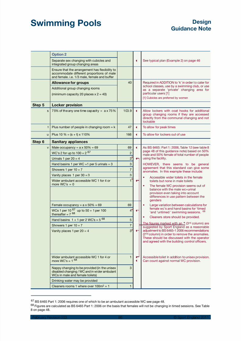
8/14/2019 Swimming Pools Design 2011 Rev3.pdf
http://slidepdf.com/reader/full/swimming-pools-design-2011-rev3pdf 87/97
Swimming Pools Design
Guidance Note
February Revision 003 86 © Sport England 2011
Option 2
3 See typical plan (Example 2) on page 46Separate sex changing with cubicles andintegrated group changing areas
Ensure that the arrangement has flexibility toaccommodate different proportions of maleand female. i.e. 1/3 male, female and buffer
Allowance for groups 40 Required in ADDITION to ‘k’ in order to cater forschool classes, use by a swimming club, or useas a separate ‘private’ changing area forparticular users [1]
[1] Cubicles are preferred by women
Additional group changing rooms
(minimum capacity 20 places x 2 = 40)
Step 5 Locker provision
s 75% of the any one time capacity = a x 75% 103.9 3 Allow lockers with coat hooks for additionalgroup changing rooms if they are accessed
directly from the communal changing and notlockable
t Plus number of people in changing room = k 47 3 To allow for peak times
u Plus 10 % = (s + t) x 110% 166 3 To allow for lockers out of use
Step 6 Sanitary appliances
v Male occupancy = a x 50% = 69 69 3
3
3
3
3
33
As BS 6465: Part 1: 2006, Table 12 (see table 8page 48 of this guidance note) based on 50%male and 50% female of total number of peopleusing the facility.
HOWEVER, there seems to be generalagreement that this standard can give someanomalies. In this example these include:
• Accessible wider toilets in the femaletoilets but none in male toilets
• The female WC provision seems out ofbalance with the male wc+urinalprovision even taking into accountdifferences in use pattern between thegenders
• Large variation between calculations forfemale wc’s and hand basins for ‘timed‘and ‘untimed ‘ swimming sessions. 68
• Cleaners store should be provided.
The figures marked with an * (3rd column) aresuggested by Sport England as a reasonableadjustment to BS 6465-1 2006 recommendations(2nd column) in order to remove the anomalies.
These should be discussed with the operatorand agreed with the building control officers.
Accessible toilet In addition to unisex provision.Can count against normal WC provision.
WC’s 2 for up to 100 = 2 67 2
Urinals 1 per 20 = 4 3
Hand basins 1 per WC +1 per 5 urinals = 3 3
Showers 1 per 10 = 7 7
Vanity places 1 per 30 = 3 3
Wider ambulant accessible WC 1 for 4 ormore WC’s = 0
1
Female occupancy = a x 50% = 69 69
WCs 1 per 10 67 up to 50 + 1 per 100thereafter = 7 68
4
Hand basins 1 + 1 per 2 WC’s = 5 68 5
Showers 1 per 10 = 7 7
Vanity places 1 per 20 = 4 3
Wider ambulant accessible WC 1 for 4 ormore WC’s = 1 68
1
Nappy changing to be provided (in the unisexdisabled changing / WC and in wider ambulantWCs in male and female toilets)
3
Drinking water may be provided
Cleaners rooms 1 where over 100m2 = 1 1
*
*
*
*
67 BS 6465 Part 1: 2006 requires one of which to be an ambulant accessible WC see page 48.68 Figures are calculated as BS 6465 Part 1: 2006 on the basis that females will not be changing in timed sessions. See Table8 on page 48.

8/14/2019 Swimming Pools Design 2011 Rev3.pdf
http://slidepdf.com/reader/full/swimming-pools-design-2011-rev3pdf 88/97
Swimming Pools Design
Guidance Note
February Revision 003 87 © Sport England 2011
Appendix 4: Improvement and alterations
to existing swimming poolsGeneral
These notes give a general overview of issues to beconsidered in a swimming pool refurbishment project.
Projects will vary greatly and depend on the age,levels of maintenance and the location of theparticular building. Many historic swimming poolbuildings from the late 1800’s and the early 1900’smay have had a number of alterations over theirlifetime, but still justify a major investment to ensurea continued future role as valued public facilitiesand local landmarks. Swimming pools that have
been built more recently will also need variousdegrees of alteration and refurbishment to keepabreast of changes in legislation, user/operatorneeds and maintain customer appeal.
69 Ref. Sport Council Guidance Note ‘Swimming Pools-Improvement and Alterations to Existing Pools’ and SportScotland Digest ‘Pool Refurbishment V Pool Replacement’.
Strategic review:
Consult with ASA / Sport England /•Stakeholders
Design and options appraisals:
Cost / benefits / risks•
Defining scope of project
Project initiation
Technical appraisals:
Building condition•
Record information•
Development constraints•
Initial appraisal of desirableupgrades:
Benchmarking•
Visioning•
Market research / user surveys /• stakeholder consultation
Process Diagram
Refurbishment should be seen as an ongoing partof the process to maintain the national stock ofswimming pools.
Subject to individual maintenance regimes, manyswimming pool buildings are likely to require major
replacement of their services after 20 to 30 yearsand this can be a trigger for a more generalupgrade of the facility.
Historic renovation together with sensitive upgrade tomeet current standards
With appropriate expertise and advice most
swimming pools can be successfully improved andremodelled, but this may not always be the rightanswer. It is recommended that a strategic reviewis carried out every 5 to 10 years 69 to determinewhether it is advisable to revitalise the existingbuilding or to demolish and replace it.

8/14/2019 Swimming Pools Design 2011 Rev3.pdf
http://slidepdf.com/reader/full/swimming-pools-design-2011-rev3pdf 89/97
Swimming Pools Design
Guidance Note
February Revision 003 88 © Sport England 2011
Fundamental questions
See previous Section 2 and the planning advice onthe Sport England website to help address suchfundamental questions as:
Is the building in a suitable location and easily•accessed from the surrounding communities?
Does it still meet the needs of the local community?•
What additional new facilities might be beneficial?•
Does the building have the potential to be•altered to provide these?
What are the implications of competing•facilities in the immediate area that might
attract the same market?
How does the performance of the existing•building fabric and services rate against currentstandards?
Is there the potential to reduce the building•operating cost?
Can the cost of improvement or alteration,•possibly with a long period of closure, be justified compared with a new build option?
Should the existing building be closed, or•converted to some other use?
Initial assessments
See Sport England web site for a separate‘Swimming Pools Audit Checklist’ for making aninitial assessment of desirable upgrades andrefurbishments under the following headings:
Site•
Building organisation•
Building services•
Building construction•
Building operation•
Feasibility work
It is advisable that a detailed feasibility study shouldbe undertaken by specialist consultants withexperience of swimming pool design, constructionand refurbishment before deciding on the scope ofa particular project. This should be in conjunctionwith a market assessment and user surveys andconsultations, to ascertain user’s perceptions of thefacility. Any constraints such as planning or historicbuilding considerations should also be fullyidentified and their implications understood.
Image for public consultation on proposals to restore and upgrade an historic swimming pool building

8/14/2019 Swimming Pools Design 2011 Rev3.pdf
http://slidepdf.com/reader/full/swimming-pools-design-2011-rev3pdf 90/97
Swimming Pools Design
Guidance Note
February Revision 003 89 © Sport England 2011
Pool tank construction:
Understanding the form of
construction and the potential
life expectancy of key
elements of the building is
critical:
Pool tanks•
Roof structure•
Environmental services•
Measured Survey:
The study should include a measured survey of thebuilding. If the original as built drawings andspecifications are available, they can provideuseful guidance. It may also be useful to contactthe original design team, if possible, for furtherinformation or clarification of details. However, aphysical check will always be essential, as fewbuildings remain unaltered during their life span.
Condition survey:
A thorough survey of the building fabric andstructure, including the services (electrical,mechanical and engineering) should be undertaken.
This should be carefully assessed to create adetailed schedule of the remedial work that will berequired to keep the facility in use, whether or notother improvements are made. This will entaildetailed inspection of key areas of the building toidentify potential defects e.g. roof voids, concealedsteelwork and may involve invasive testing.
It is also important to ascertain the cause of anydefect discovered during the survey.
Construction appraisal:
A constructional appraisal should be carried outon a building elemental basis - working through
each of the external and internal spaces, checkingthe roof, wall and floor construction, including anyfixtures and fittings, and deciding which part of theconstruction needs to be upgraded and how. Thisappraisal should include the condition of theexisting pool tank(s). Additional specialist surveysand investigations may be required for key issuessuch as the construction/condition of the pooltanks or underground drainage.
Analysis of improvement options
It is recommended that a systematic approach isfollowed to the development of options foraddressing the identified shortcomings in thebuilding. The overall planning and design can beexamined by tracing the route different user groupswould take from the site boundary to the pool halland identifying any potential problems. A similarexercise can assess how easy the building is tooperate. The quality for the ‘user’s experience’ canbe gauged from surveys/questionnaires of existingusers and consultation with interested groups.
Typical items:
Upgrade the overall image:•
To increase the appeal and viability of thefacility through elements such as graphics,colour or planting.
Making the facility more accessible to all•
sections of the community:
For example family/accessible changingcubicles, easy going access steps to thepool(s) and submersible wheelchair lifts.
Alterations to the layout:•
To increase customer appeal, and make the
planning more efficient, and possibly save onstaffing costs.
Alterations to key areas:•
For example - to upgrade the changing areasto make them more comfortable and attractiveto users.
Elimination of planning or detailed design•
features that adversely affects the facility:
To meet current safety and best practicestandards.
Upgrade the building fabric and replace•
services:
To improve the internal environmentalconditions and meet energy efficiencystandards.
Alterations of the pool tank configuration and•
profile:
To increase capacity and range of users, and formore flexible programming of uses (for instanceby introducing a movable floor, bulkhead, easygoing steps and submersible lift).
Extension of the existing building to provide•
additional sports and recreation facilities:
To increase the appeal and viability of thefacility.

8/14/2019 Swimming Pools Design 2011 Rev3.pdf
http://slidepdf.com/reader/full/swimming-pools-design-2011-rev3pdf 91/97
Swimming Pools Design
Guidance Note
February Revision 003 90 © Sport England 2011
70 From SE Guidance Note ‘Changing and related Amenitiesin Public Indoor Swimming Pools.
D.Ch
/WC
Male
Change
Female
Change
Male
route
Unisex
route
Female
route
CPFF/D
F/D
F/D
F/DSh
Sh
Sh
D.Sh
Cl.St DWC
Shallow water Shallow water
To allow new uses to be made of the existing
facilities - say, by upgrading the specificationof a school pool to permit use by the widercommunity or providing essentialaccommodation such as community changing,a reception or an office.
Project Constraints
All the various constraints will need to beunderstood and factored into the design appraisalsfor the project. The following will normally beamong them:
The estimated cost of the work, including VAT•and professional fees.
If the cost of improving the pool building is•greater than 60% of the cost of building new,then a rebuild may be a better option 70.
The implications of refurbishment may require•a prolonged period of closure, resulting inreduction in public services and income.
The physical constraints imposed by the•existing building - for example, structural anddimensional limitations, structural form andmethod of construction.
The physical constraints imposed by the•
surrounding site, including access roads, carparking, electricity and gas supply lines,drainage, existing buildings, trees and siteboundary.
Existing ground conditions and water table•level (if the building is to be extended oralterations are to be made to the ground floorand pool tank construction).
The requirements of specific user groups such•as schools and people with disabilities. If thereare changes in floor level, it can be difficult toprovide wheelchair access to various publicareas. A compromise solution may have to
found, so it may be necessary to involve thekey user groups in establishing what can orcannot be achieved to meet their particularneeds.
The retention of some or all of the existing•historical building features that are worthy ofpreservation.
Any planning constraints that have a bearing•on the existing design.
Changing:
User’s perception of changing rooms can beimproved in many projects by fresh decoration andreplacement of lockers, benches and other itemsof equipment. However, there may be otherchallenges in relation to the space and circulationnecessary to meet currents standards. Forexample, the ease of disabled access, the numberof showers and toilets and the safety of theentrance / egress to the swimming pool hall mightalso need to be considered.
There may be opportunities for a majorreorganisation into a ‘village’ changing or theincorporation of a unisex route with familychanging cubicles and disabled changes to beincorporated into the traditional male and femalechanging layout.
The separate male and female changing room layout isre-organised and refurbished to allow wheelchair accessand a unisex zone that has family / disabled changing
Key:
F/D Disabled / family accessible changing cubicle
D.Ch/WC Unisex accessible changing room with WC
CPF Changing Places Facility
DWC Unisex accessible WC
D.Sh Unisex accessible shower cubicle
Cl. St Cleaners store
Sh Shower
Examples of typical refurbishment projects

8/14/2019 Swimming Pools Design 2011 Rev3.pdf
http://slidepdf.com/reader/full/swimming-pools-design-2011-rev3pdf 92/97
Swimming Pools Design
Guidance Note
February Revision 003 91 © Sport England 2011
33.3m main pool modified to include a movable bulkheadto divide into two pool areas and ‘easy access steps’,submersible lift and recessed ladders added
New slip-resistant tile floor, lockers and accessible cubicles to upgrade a 1980’s changing area
Floating boom to divide the pool into separate areas
Pool configuration
A 33.3m main pool can be re-configured by theinclusion of a movable bulkhead that allows 25mtraining and the option of a separate learner pool.The access ladders are also recessed into the poolside wall and ‘easy access stairs’ and asubmersible lift can also be included.
2 0 m
Recessed ladders
Submersible Lift
Easy access stairs
2 5 m
Movable bulkhead togive 20/25m lengths
and learner area

8/14/2019 Swimming Pools Design 2011 Rev3.pdf
http://slidepdf.com/reader/full/swimming-pools-design-2011-rev3pdf 93/97
Swimming Pools Design
Guidance Note
February Revision 003 92 © Sport England 2011
Refurbishment systems
Typically, refurbishment systems consist ofstainless steel wall panels with a factory appliedPVC finish and a loose laid PVC sheet to the floor.Such pool linings will marginally reduce thedimensions of the pool and it may then notconform to the necessary length for competition.
New pool equipment
The upgrade of fixed and loose pool equipmentcan also have an impact on the use, flexibility andcustomer appeal of a pool.
Portable diving boards can add an interesting ‘fun’element to a traditional pool that has sufficient depth ofwater in an area that can be segregated from otherbathers
Temporary turning boards fixed to lane ropes to allow competition training
Pool Edge:
Subject to the pool construction, the pool edgemight be changed from ‘freeboard’ to ‘deck level’to achieve better water hygiene (by removing ahigher proportion of the polluted water from thesurface) and to allow easier access / egress byswimmers.
There are proprietary pre-fabricated stainless steelre-lining systems that have an integrated decklevel feature that can fit in the space of aconventional scum channel. Alternatively the sameresult can be achieved with conventional BS 8007concrete and tiling.
Some systems offer a deck level channel to replace anexisting scum channel

8/14/2019 Swimming Pools Design 2011 Rev3.pdf
http://slidepdf.com/reader/full/swimming-pools-design-2011-rev3pdf 94/97
Swimming Pools Design
Guidance Note
February Revision 003 93 © Sport England 2011
Appendix 5: Further information on
Leisure PoolsThe Sports Council Handbook of Sport andRecreational Building Design: Volume 3 is still auseful reference to the provision of leisure poolfacilities. However, discussion with experiencedspecialist consultants should take place toestablish new trends and changes since thehandbook was written.
The concept of leisure pools goes back to the 70’swhere free-form shaped pools and various waterfeatures started to be used to widen customerappeal.
Leisure pools aim more towards recreationalswimming, with water play features, and a moreinteresting environment that attract all the family.Individual buildings vary greatly and some showconsiderable inventiveness and complexity: Largeareas of shallow water or beaches with wavemachines; moving water rides; geysers; watercannons and theming to create a strong facilitybrand such as ‘Coral Reef’, ‘Splash’ or ‘the TimeCapsule’.
Some larger centres have become popular‘destination’ centres where families travelconsiderable distance for a ‘day out’. Others areconceived as regional tourist attractions.
Alternatively, leisure features can be seen as a wayto complement a conventional swimming pool 71.For example, the overall leisure pool shape canaccommodate 25m lane swimming and at thesame time have linking areas to a beach or shallowwater. Similarly a 25m or 50m rectangular poolmight be complemented by the provision of alearner pool which contains some water playfeatures.
The use of colour, internal planting and excitingdesign has had a steady influence on generalswimming pool design and to some extent raisedthe level of customer expectation.
Leisure water/features can add significantly to thecomplexity and costs of a project. Key issuesinclude:
The increase on the overall size of the facility:•wider surrounds, beach areas and planting
areas.Increased height requirement for facilities such•as flumes and water rides.
Increased circulation space to cope with very•large numbers of users. Particularly duringschool holidays.
The time bathers spend in the pool can be up•to several hours.
Careful consideration of the safe occupancy•rate for the pool in the context of HSE / SErecommendations 72.
The need for increased catering facilities.•
Increased requirements of car and coach•parking and external site areas.
High bathing loads due to high number of•bathers being concentrated in shallow waterareas 73.
71 Sport Council Policy document ‘Provision forSwimming’.
72 The HSE/SE guide HSG179 ‘Managing Health & Safetyin Swimming Pools’ uses 3m2 / person as the base point forsafe maximum occupancy for un-programmed sessions.The depth, size, shape and number of swimmerscongregating around some features all need to be factoredinto the risk assessment for a leisure pool.
73 The PWTAG ‘Swimming Pool Water – Treatment & QualityStandards’ refers to water treatment rates being based on abathing loads of 2.2m2 /person for water less than 1m deep.
Leisure pools can combine a wide range of excitingwater rides attracting the public in large numbers
Water rides can be highly complex requiring a clearunderstanding of their three dimensional paths througha building during design stages

8/14/2019 Swimming Pools Design 2011 Rev3.pdf
http://slidepdf.com/reader/full/swimming-pools-design-2011-rev3pdf 95/97
Swimming Pools Design
Guidance Note
February Revision 003 94 © Sport England 2011
Appropriate water treatment and environmental•systems to reduce the levels of water andairborne chemicals, to minimise unwantedeffects on bathers.
Higher water temperatures, particularly in the•shallow water areas.
Need for cooling and dehumidification to•maintain comfort conditions for spectators.
Features are increasingly sophisticated to cater forusers who expect thrills and excitement ratherthan exercise and may include:
Wave pools with beach•
Complex pool shapes•
Lazy Rivers or falling rapids (usually with•rubber rings)
Fast moving water e.g. Rapids, whirlpools•
Warm spa pools•
Water features: e.g. water jets and canon,•geysers, water sprays
Water based specialist play equipment e.g.•small slides, pirate ships etc
Outdoor pool links•
Surfing pools or laminar flow water rides•
Water slides and flumes, some of which can•be more like roller coasters.
The majority of Leisure Pools are designed anddeveloped by specialist design consultants whohave built up extensive knowledge, experienceand expertise over many years.
Early design consultations should take place withwell-established specialist equipment suppliersand installers, particularly those experienced inwater treatment and features design, as these havespecific area and volume impacts on thebuilding.
Theming is an integral part of the leisure pool, adding to the user’s enjoyment and excitement
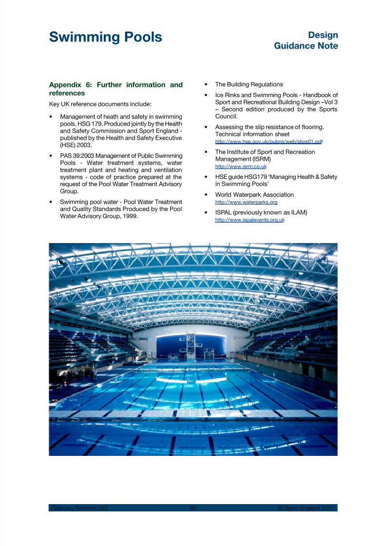
8/14/2019 Swimming Pools Design 2011 Rev3.pdf
http://slidepdf.com/reader/full/swimming-pools-design-2011-rev3pdf 96/97
Swimming Pools Design
Guidance Note
February Revision 003 95 © Sport England 2011
Appendix 6: Further information and
referencesKey UK reference documents include:
Management of heath and safety in swimming•pools. HSG 179. Produced jointly by the Healthand Safety Commission and Sport England -published by the Health and Safety Executive(HSE) 2003.
PAS 39:2003 Management of Public Swimming•Pools - Water treatment systems, watertreatment plant and heating and ventilationsystems - code of practice prepared at therequest of the Pool Water Treatment Advisory
Group.
Swimming pool water - Pool Water Treatment•and Quality Standards Produced by the PoolWater Advisory Group, 1999.
The Building Regulations•
Ice Rinks and Swimming Pools - Handbook of•Sport and Recreational Building Design –Vol 3– Second edition produced by the SportsCouncil.
Assessing the slip resistance of flooring.•Technical information sheethttp://www.hse.gov.uk/pubns/web/slips01.pdf
The Institute of Sport and Recreation•Management (ISRM)http://www.isrm.co.uk
HSE guide HSG179 ‘Managing Health & Safety•in Swimming Pools’
World Waterpark Association•http://www.waterparks.org
ISPAL (previously known as ILAM)•http://www.ispalevents.org.uk

8/14/2019 Swimming Pools Design 2011 Rev3.pdf
http://slidepdf.com/reader/full/swimming-pools-design-2011-rev3pdf 97/97
Swimming Pools Design
Guidance Note
Alternative languages and Formats:
This document can be provided in alternative languages, or alternative formatssuch as large print, Braille, tape and on disk upon request.Call the Sport England switchboard on 08458 508 508 for more details.
Information Prepared By:
Sport England, Robin Wilson Consulting & S&P Architects
Acknowledgements:
Sport England is indebted to the individuals and organisations that have contributed to this guidance notewith excellent advice, information and photographic material. In particular (in alphabetical order):
Disclaimer
Amendments, alterations and updates to this document may take place from time to time. When usingSport England Design Guidance you should always download the documents at the time of use in order toensure that you are referring to the most up-to-date information. The term Design Guidance should be takento imply the minimum standards required to produce best practice solutions acceptable to Sport England.
This document is for information only. Whilst every effort has been made to ensure the accuracy of thisDesign Guidance Note and all information contained herein, Sport England, or its agents, shall not be heldresponsible or liable to any party in respect of any loss, damage or costs of any nature arising directly orindirectly from reliance placed on this information. The views expressed are not intended to take awayor diminish the responsibility of the user to comply with current or future legislation and if there are anyconflicts between the views expressed in this document and legislation the latter takes precedence
ADM Floors ISRM/ PWTAG: Ralph Riley Amateur Swimming Association LA Architects: Mike Lawless
Arcblue MSG Consult: Malcolm Graham
Arjo UK Myrtha Pools
Austin Design & Manufacture Ltd Power Master Ltd.
Barr + Wray Roberts Limbrick: Philip Dryden
David Bosher Andrew Southall
Carlos Dublanc S&P Architects
Feilden Clegg Bradley: Andy Couling The Access Consultancy: Brian Towers
Health & Safety Executive Tim Ronalds Architects
Kirby Swim Equip Pty Limited Charlotte Wood
Greenwich Leisure Ltd: Roy Clarke John Whitby