sutherland+ppt_open source
DESCRIPTION
Open Source Document_Hip Prosthesis in Radiation TherapyTRANSCRIPT

7/21/2019 Sutherland+PPT_Open Source
http://slidepdf.com/reader/full/sutherlandpptopen-source 1/91
Radiation Therapy in Patients with
Implanted
Hip
Prostheses:
Phantom Study Results
Keith Sutherland, RTT CMD
Radiation Oncology Department Cancer Care Manitoba
Winnipeg Canada
7/21/2019 Sutherland+PPT_Open Source
http://slidepdf.com/reader/full/sutherlandpptopen-source 2/91
Disclosure
• Speaker has received travel funding from Varian
Medical
Systems.
• A portion of this project was funded by the
Cancer
Care
Manitoba
Foundation.

7/21/2019 Sutherland+PPT_Open Source
http://slidepdf.com/reader/full/sutherlandpptopen-source 3/91
Acknowledgments
Medical Physics:
Dave Sasaki
Marlon EvanRadiation Therapy:
John Ioculano
Machine Shop:
Todd Boyer
Chad
Harris
Roy Norton
Cancer
Care
Manitoba
Foundation
7/21/2019 Sutherland+PPT_Open Source
http://slidepdf.com/reader/full/sutherlandpptopen-source 4/91
Presentation Outline
• Overview of hip prostheses
• Problems delivering RT:
– Image Quality
– Dose Uncertainty
• Case Study: SCC Vagina, Prostate Bed
• Phantom Creation
• Research Results
• Conclusions
7/21/2019 Sutherland+PPT_Open Source
http://slidepdf.com/reader/full/sutherlandpptopen-source 5/91
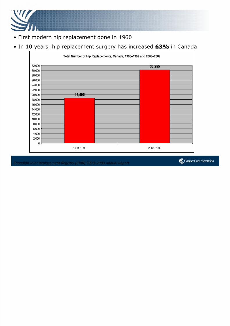
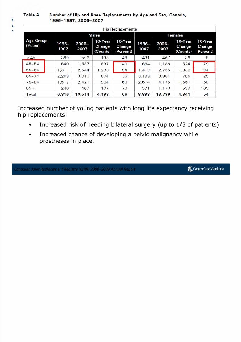
Canadian Joint Replacement Registry (CJRR) 2008–2009 Annual Report
• First modern hip replacement done in 1960
• In 10 years, hip replacement surgery has increased 63% in Canada
Total Number of Hip Replacements, Canada, 1998–1999 and 2008–2009
18,595
30,255
0
2,000
4,000
6,0008,000
10,000
12,000
14,000
16,000
18,000
20,000
22,000
24,000
26,000
28,000
30,000
32,000
1998–1999 2008–2009
7/21/2019 Sutherland+PPT_Open Source
http://slidepdf.com/reader/full/sutherlandpptopen-source 6/91
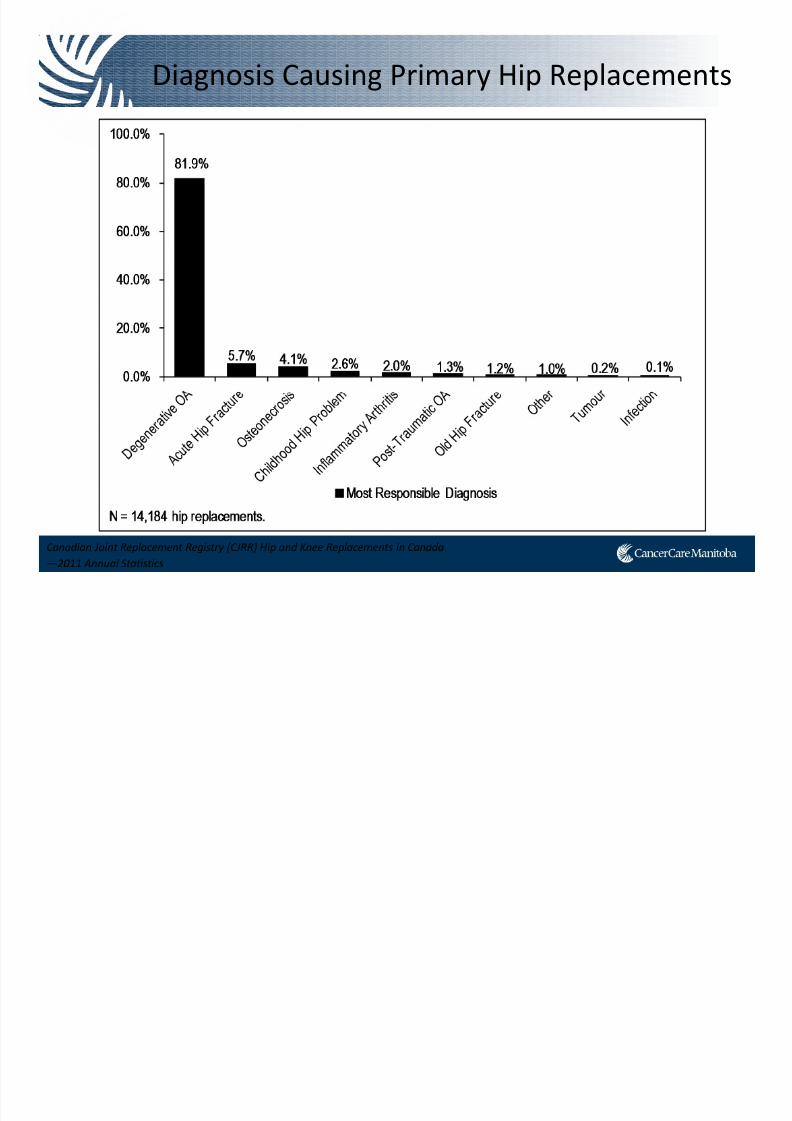
Diagnosis Causing Primary Hip Replacements
Canadian Joint Replacement Registry (CJRR) Hip and Knee Replacements in Canada
—2011 Annual Statistics
7/21/2019 Sutherland+PPT_Open Source
http://slidepdf.com/reader/full/sutherlandpptopen-source 7/91
Canadian Joint Replacement Registry (CJRR) 2008–2009 Annual Report
Increased number of young patients with long life expectancy receivinghip replacements:
• Increased risk of needing bilateral surgery (up to 1/3 of patients)
• Increased chance of developing a pelvic malignancy whileprostheses in place.
7/21/2019 Sutherland+PPT_Open Source
http://slidepdf.com/reader/full/sutherlandpptopen-source 8/91
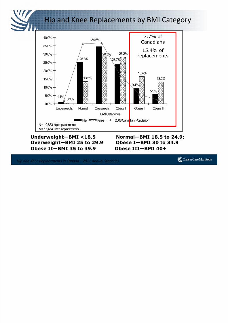
Hip and Knee Replacements in Canada—2011 Annual Statistics
Hip and Knee Replacements by BMI Category
Underweight—BMI <18.5 Normal—BMI 18.5 to 24.9;Overweight—BMI 25 to 29.9 Obese I—BMI 30 to 34.9
Obese II—BMI 35 to 39.9 Obese III—BMI 40+
1.1%
25.3%
34.6%
23.7%
9.4%
5.9%
0.3%
13.5%
28.3% 28.2%
16.4%
13.2%
0.0%
5.0%
10.0%
15.0%
20.0%
25.0%
30.0%
35.0%
40.0%
Underweight Normal Overweight Obese I Obese II Obese III
BMI Categories
Hip Knee 2008 Canadian Population
N = 10,883 hip replacements.
N = 16,454 knee replacements.
7.7% ofCanadians
15.4% ofreplacements

7/21/2019 Sutherland+PPT_Open Source
http://slidepdf.com/reader/full/sutherlandpptopen-source 9/91
Total Hip Replacement
Most often done for Osteoarthritis
1. Compartment opened
2. Femur neck is cut off
3. Acetabulum reamed, cup placed
Mirza et al., The Open Orthopedics Journal, 4:169-80, 2010.
7/21/2019 Sutherland+PPT_Open Source
http://slidepdf.com/reader/full/sutherlandpptopen-source 10/91
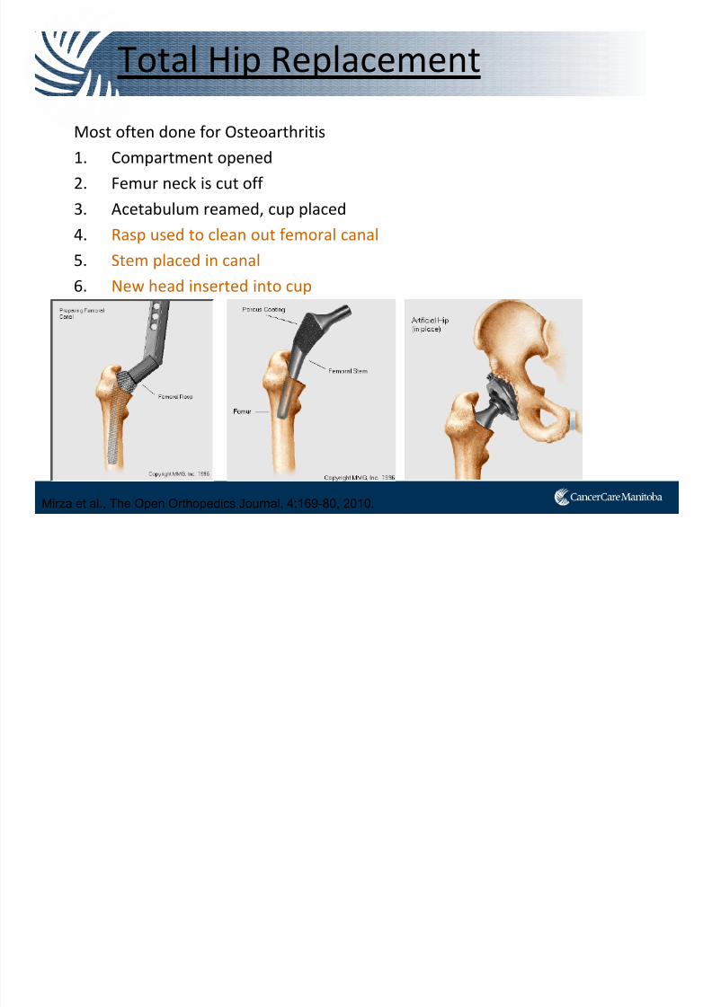
Total Hip Replacement
Most often done for Osteoarthritis
1. Compartment opened
2. Femur neck is cut off
3. Acetabulum reamed, cup placed
4. Rasp used to clean out femoral canal
5. Stem placed in canal
6. New head inserted into cup
Mirza et al., The Open Orthopedics Journal, 4:169-80, 2010.
7/21/2019 Sutherland+PPT_Open Source
http://slidepdf.com/reader/full/sutherlandpptopen-source 11/91
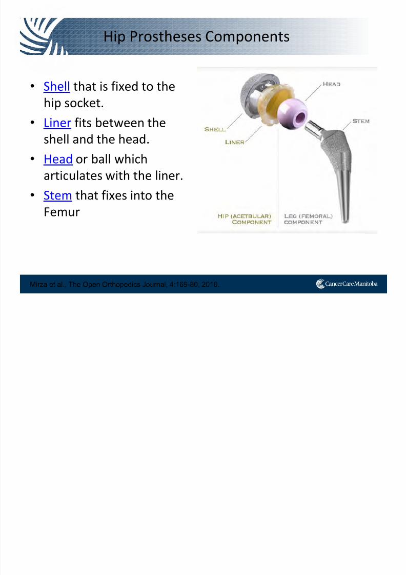
Hip Prostheses Components
• Shell that is fixed to the
hip socket.
• Liner fits between the
shell and the head.
• Head or ball
which
articulates with the liner.
• Stem that fixes into the
Femur
Mirza et al., The Open Orthopedics Journal, 4:169-80, 2010.
7/21/2019 Sutherland+PPT_Open Source
http://slidepdf.com/reader/full/sutherlandpptopen-source 12/91
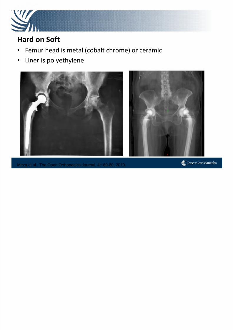
Hard
on
Soft
• Femur head is metal (cobalt chrome) or ceramic
• Liner is polyethylene
Mirza et al., The Open Orthopedics Journal, 4:169-80, 2010.

7/21/2019 Sutherland+PPT_Open Source
http://slidepdf.com/reader/full/sutherlandpptopen-source 13/91
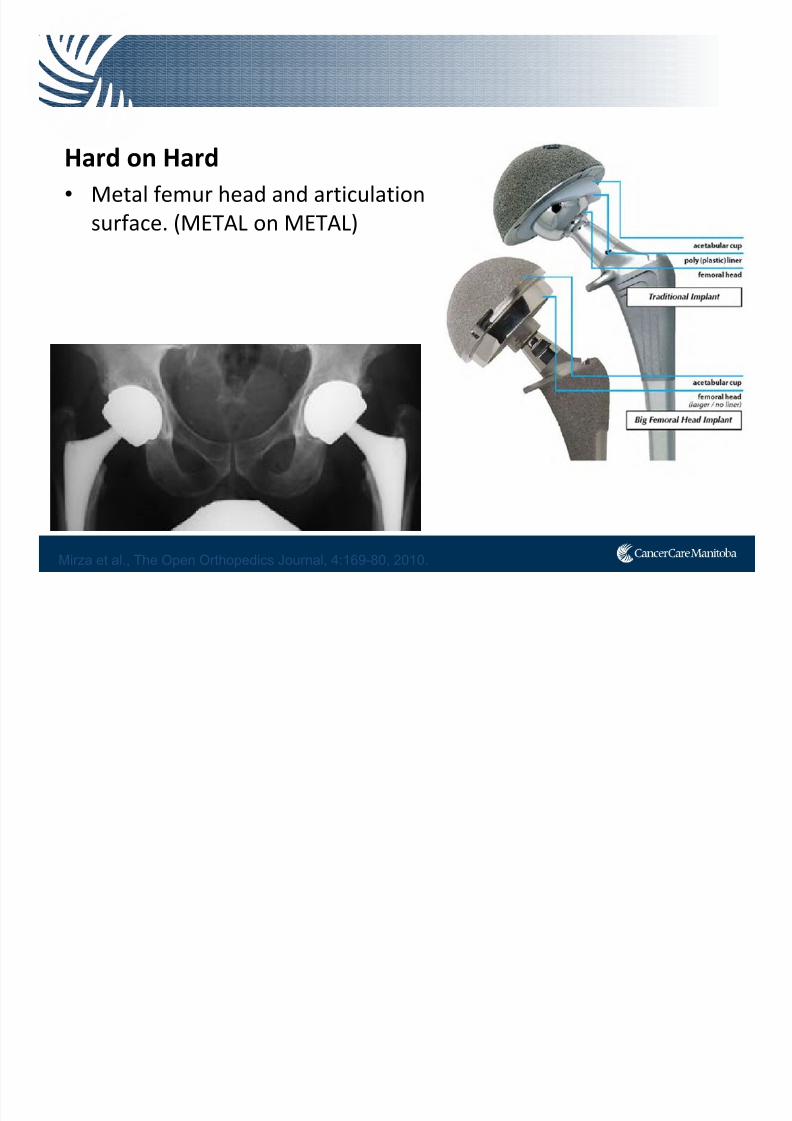
Hard on Hard
• Femur head and articulation surface
is ceramic.
(Ceramic
on
Ceramic)
Mirza et al., The Open Orthopedics Journal, 4:169-80, 2010.
7/21/2019 Sutherland+PPT_Open Source
http://slidepdf.com/reader/full/sutherlandpptopen-source 14/91
Hard
on
Hard
• Metal femur head and articulation
surface. (METAL on METAL)
Mirza et al., The Open Orthopedics Journal, 4:169-80, 2010.
7/21/2019 Sutherland+PPT_Open Source
http://slidepdf.com/reader/full/sutherlandpptopen-source 15/91
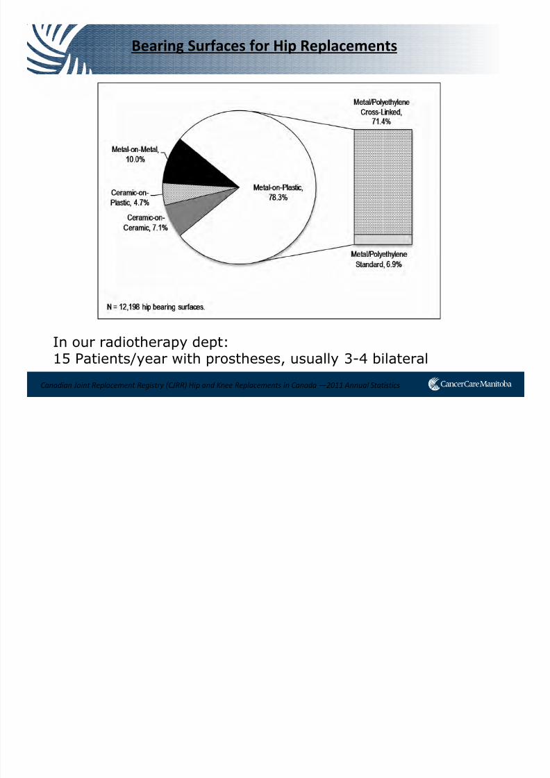
Bearing Surfaces for Hip Replacements
In our radiotherapy dept:15 Patients/year with prostheses, usually 3-4 bilateral
Canadian Joint Replacement Registry (CJRR) Hip and Knee Replacements in Canada —2011 Annual Statistics

7/21/2019 Sutherland+PPT_Open Source
http://slidepdf.com/reader/full/sutherlandpptopen-source 16/91
Problems
7/21/2019 Sutherland+PPT_Open Source
http://slidepdf.com/reader/full/sutherlandpptopen-source 17/91
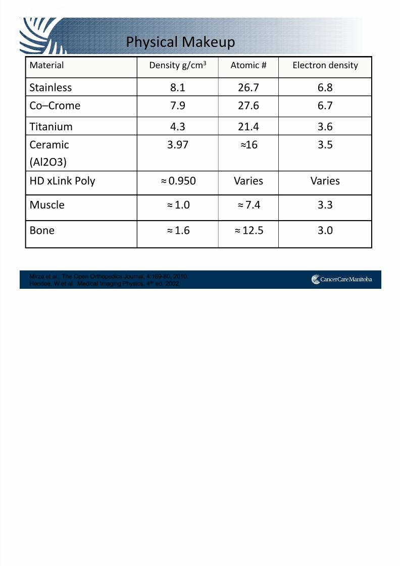
Physical Makeup
Mirza et al., The Open Orthopedics Journal, 4:169-80, 2010.
Hendee, W et al. Medical Imaging Physics, 4th ed. 2002
Material Density g/cm3 Atomic # Electron density
Stainless 8.1 26.7 6.8
Co–Crome 7.9 27.6 6.7Titanium 4.3 21.4 3.6
Ceramic
(Al2O3)
3.97 ≈16 3.5
HD xLink Poly ≈0.950 Varies Varies
Muscle ≈1.0 ≈7.4 3.3
Bone ≈1.6 ≈12.5 3.0
7/21/2019 Sutherland+PPT_Open Source
http://slidepdf.com/reader/full/sutherlandpptopen-source 18/91
0
1
2
3
4
5
6
7
8
-1000 0 1000 2000 3000 4000 5000 6000 7000 8000 9000
HU
D e n
s i t y ( g / c m
3 )
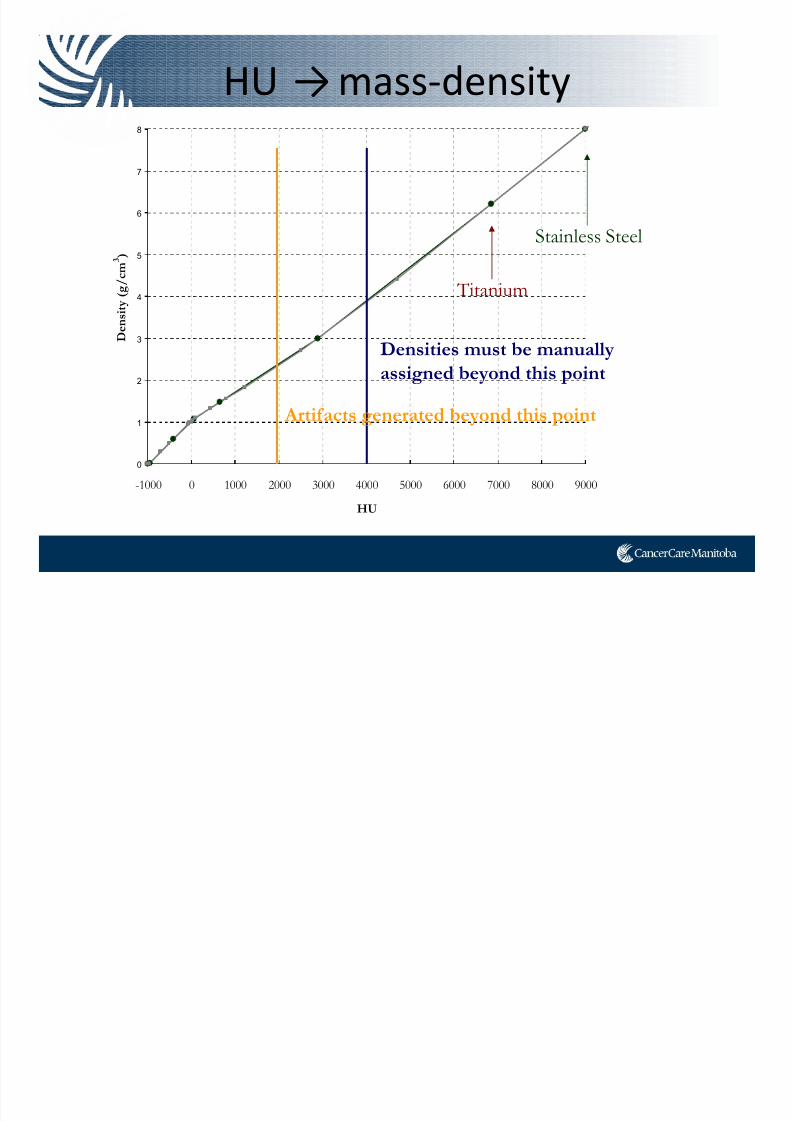
HU →mass‐density
Densities must be manually
assigned beyond this point
Titanium
Stainless Steel
Artifacts generated beyond this point
7/21/2019 Sutherland+PPT_Open Source
http://slidepdf.com/reader/full/sutherlandpptopen-source 19/91
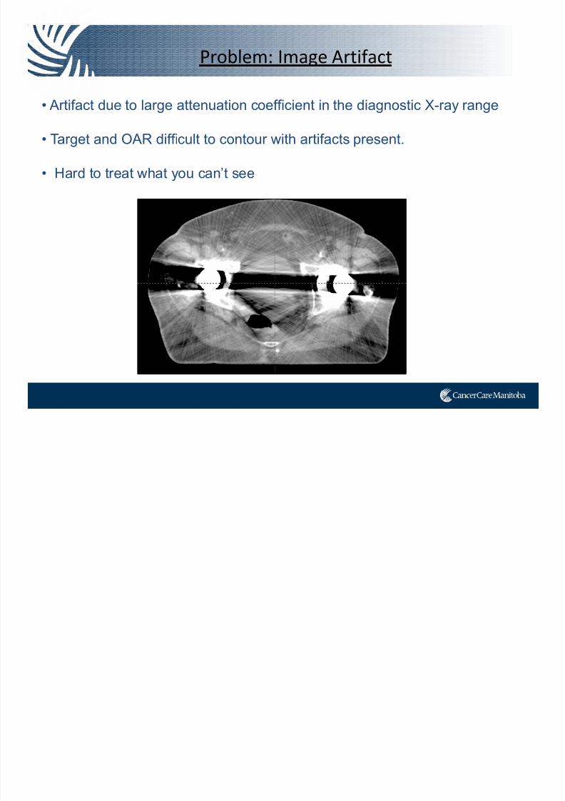
Problem: Image Artifact
• Artifact due to large attenuation coefficient in the diagnostic X-ray range
• Target and OAR difficult to contour with artifacts present.
• Hard to treat what you can’t see
7/21/2019 Sutherland+PPT_Open Source
http://slidepdf.com/reader/full/sutherlandpptopen-source 20/91
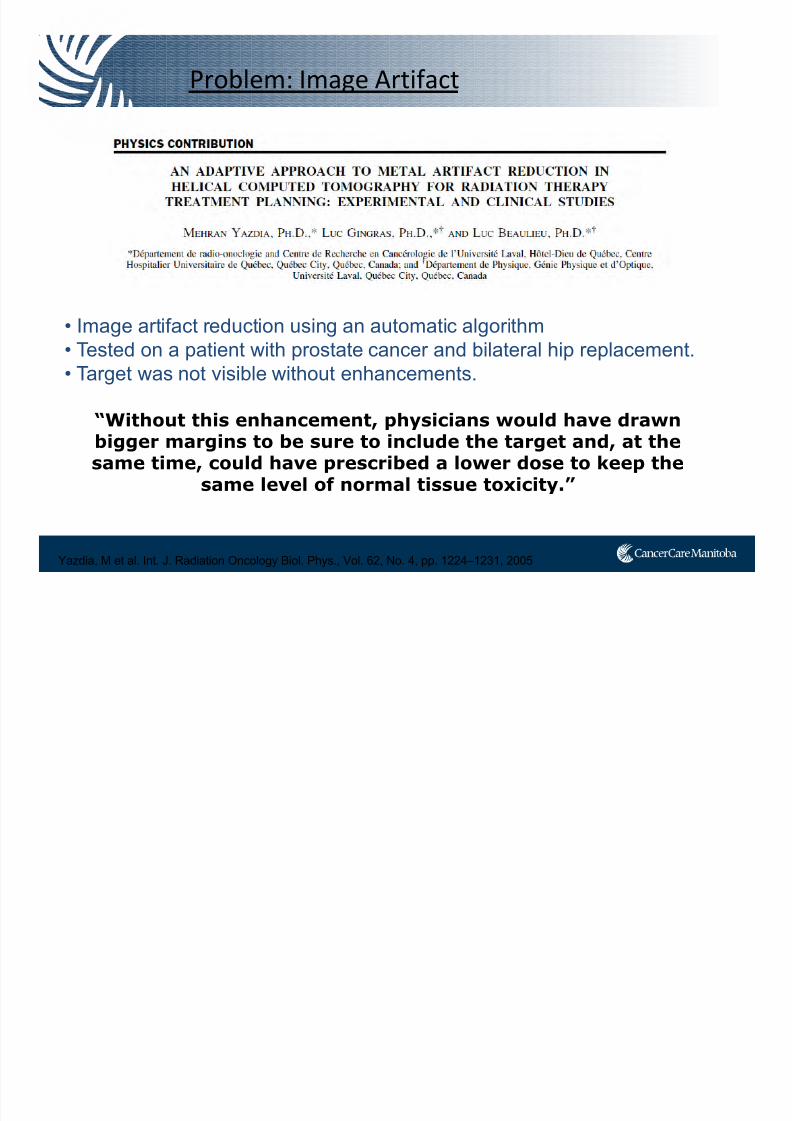
Problem: Image Artifact
• Image artifact reduction using an automatic algorithm• Tested on a patient with prostate cancer and bilateral hip replacement.
• Target was not visible without enhancements.
“Without this enhancement, physicians would have drawnbigger margins to be sure to include the target and, at thesame time, could have prescribed a lower dose to keep the
same level of normal tissue toxicity.”
Yazdia, M et al. Int. J. Radiation Oncology Biol. Phys., Vol. 62, No. 4, pp. 1224–1231, 2005
7/21/2019 Sutherland+PPT_Open Source
http://slidepdf.com/reader/full/sutherlandpptopen-source 21/91
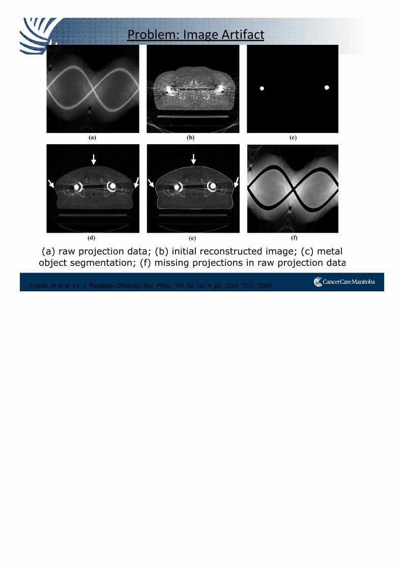
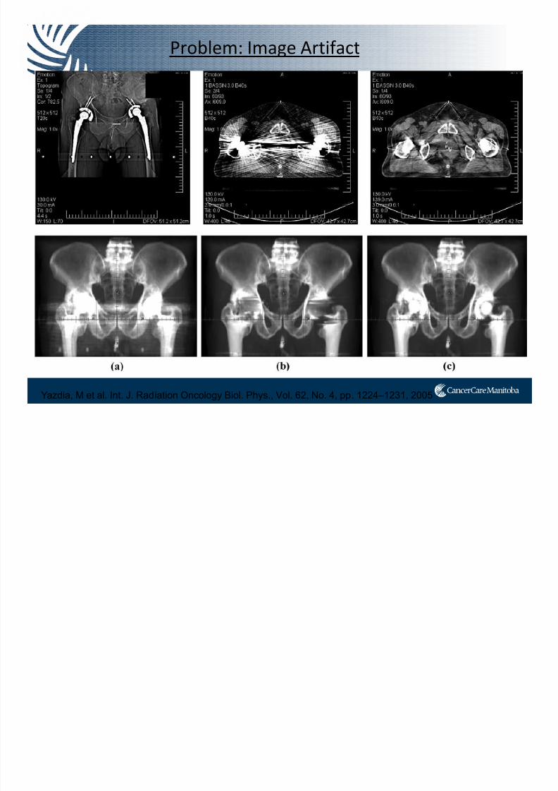
Problem: Image Artifact
(a) raw projection data; (b) initial reconstructed image; (c) metal
object segmentation; (f) missing projections in raw projection data
Yazdia, M et al. Int. J. Radiation Oncology Biol. Phys., Vol. 62, No. 4, pp. 1224–1231, 2005
7/21/2019 Sutherland+PPT_Open Source
http://slidepdf.com/reader/full/sutherlandpptopen-source 22/91
Problem: Image Artifact
Yazdia, M et al. Int. J. Radiation Oncology Biol. Phys., Vol. 62, No. 4, pp. 1224–1231, 2005
7/21/2019 Sutherland+PPT_Open Source
http://slidepdf.com/reader/full/sutherlandpptopen-source 23/91
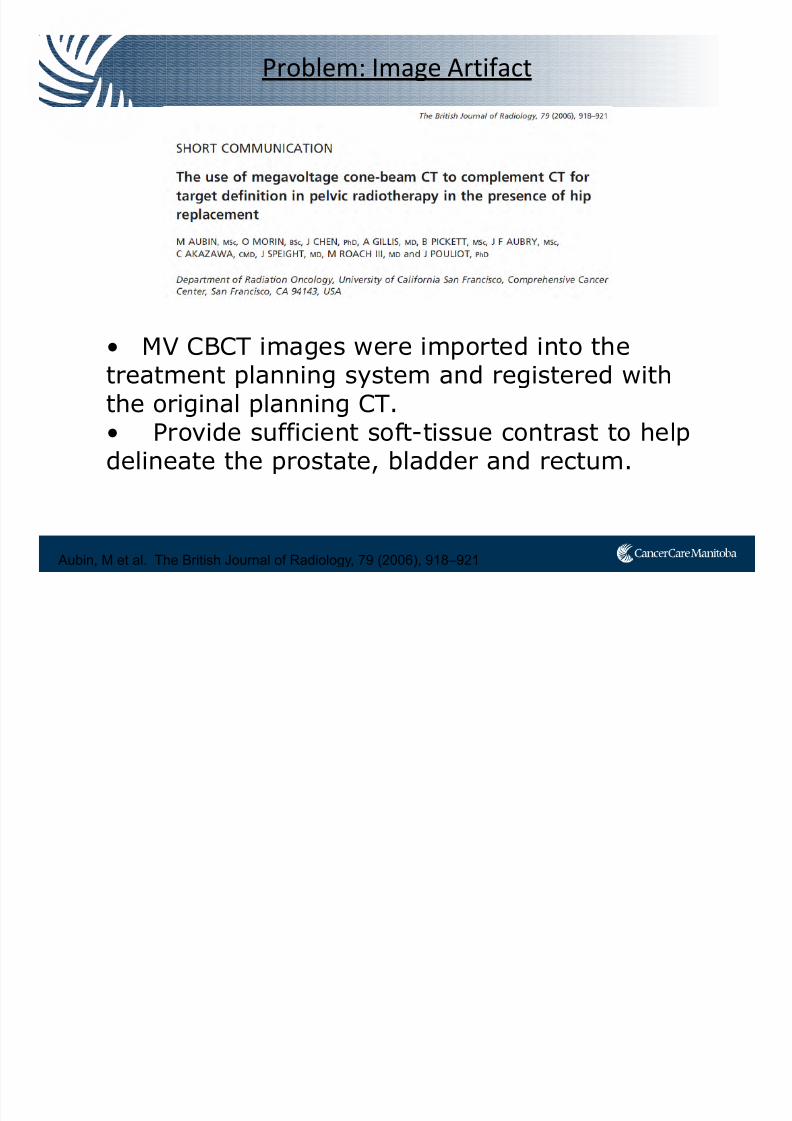
Problem: Image Artifact
• MV CBCT images were imported into thetreatment planning system and registered withthe original planning CT.
• Provide sufficient soft-tissue contrast to helpdelineate the prostate, bladder and rectum.
Aubin, M et al. The British Journal of Radiology, 79 (2006), 918–921
7/21/2019 Sutherland+PPT_Open Source
http://slidepdf.com/reader/full/sutherlandpptopen-source 24/91
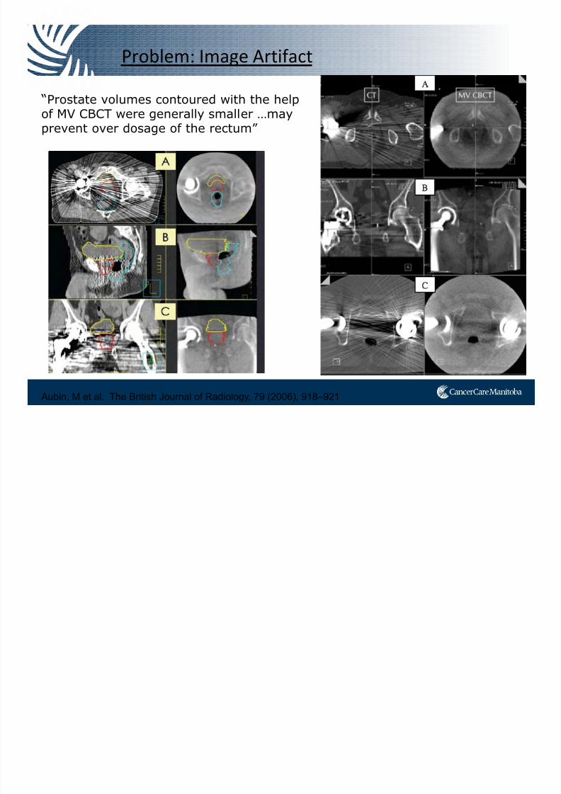
Problem: Image Artifact
Aubin, M et al. The British Journal of Radiology, 79 (2006), 918–921
“Prostate volumes contoured with the helpof MV CBCT were generally smaller …mayprevent over dosage of the rectum”
7/21/2019 Sutherland+PPT_Open Source
http://slidepdf.com/reader/full/sutherlandpptopen-source 25/91
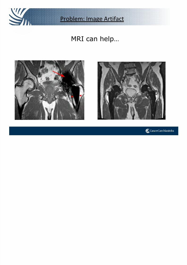
Problem: Image Artifact
MRI can help…
7/21/2019 Sutherland+PPT_Open Source
http://slidepdf.com/reader/full/sutherlandpptopen-source 26/91
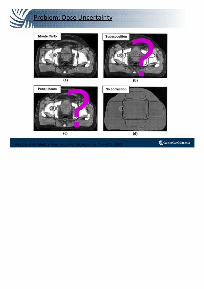
Problem: Dose Uncertainty
Keall, P et al. Medical Dosimetry, Vol. 28, No. 2, pp. 107–112, 2003
7/21/2019 Sutherland+PPT_Open Source
http://slidepdf.com/reader/full/sutherlandpptopen-source 27/91
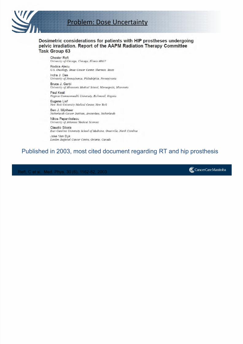
Published in 2003, most cited document regarding RT and hip prosthesis
Reft, C et al. Med. Phys. 30 (6), 1162-82, 2003
Problem: Dose Uncertainty
7/21/2019 Sutherland+PPT_Open Source
http://slidepdf.com/reader/full/sutherlandpptopen-source 28/91
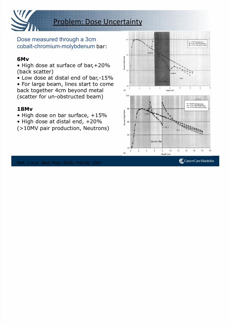
Dose measured through a 3cm
cobalt-chromium-molybdenum bar:
6Mv
• High dose at surface of bar,+20%(back scatter)• Low dose at distal end of bar,-15%• For large beam, lines start to comeback together 4cm beyond metal
(scatter for un-obstructed beam)
18Mv• High dose on bar surface, +15%• High dose at distal end, +20%
(>10MV pair production, Neutrons)
Reft, C et al. Med. Phys. 30 (6), 1162-82, 2003
Problem: Dose Uncertainty
7/21/2019 Sutherland+PPT_Open Source
http://slidepdf.com/reader/full/sutherlandpptopen-source 29/91
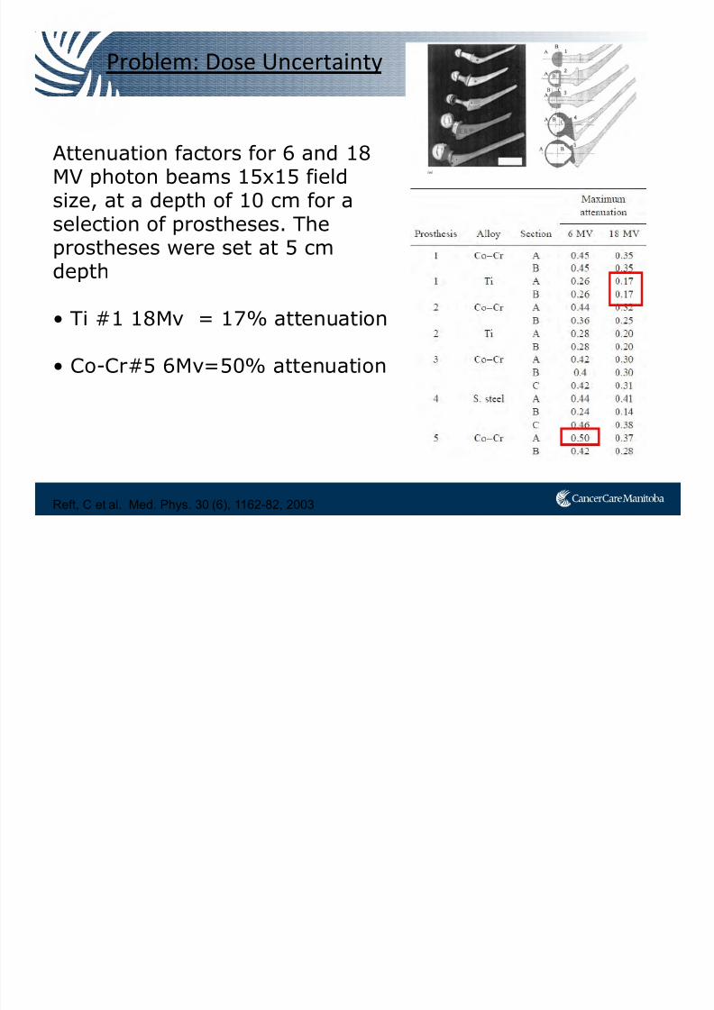
Reft, C et al. Med. Phys. 30 (6), 1162-82, 2003
Problem: Dose Uncertainty
Attenuation factors for 6 and 18MV photon beams 15x15 field
size, at a depth of 10 cm for aselection of prostheses. Theprostheses were set at 5 cmdepth
• Ti #1 18Mv = 17% attenuation
• Co-Cr#5 6Mv=50% attenuation
7/21/2019 Sutherland+PPT_Open Source
http://slidepdf.com/reader/full/sutherlandpptopen-source 30/91
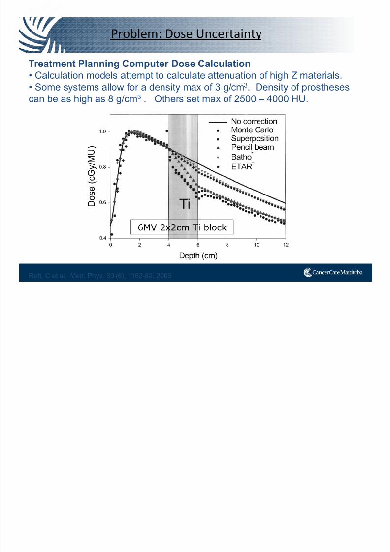
Treatment Planning Computer Dose Calculation
• Calculation models attempt to calculate attenuation of high Z materials.
• Some systems allow for a density max of 3 g/cm3. Density of prostheses
can be as high as 8 g/cm3 . Others set max of 2500 – 4000 HU.
Reft, C et al. Med. Phys. 30 (6), 1162-82, 2003
Problem: Dose Uncertainty
6MV 2x2cm Ti block
7/21/2019 Sutherland+PPT_Open Source
http://slidepdf.com/reader/full/sutherlandpptopen-source 31/91
AAPM Recommendations:
How does your treatment planning system handle high density?
1. Radiation oncologist should inform the physicist (before sim).
2. Beam arrangements that avoid theprosthesis should be done first.
The following are recommended:i. Use standard immobilizationii. Ensure prostheses does not shadow part of the target volume. For CT
planning you can edit out the streak artifactsiii. Take port/EPID to verify prosthesis does not shadow target volume
Reft, C et al. Med. Phys. 30 (6), 1162-82, 2003
Problem: Dose Uncertainty
7/21/2019 Sutherland+PPT_Open Source
http://slidepdf.com/reader/full/sutherlandpptopen-source 32/91
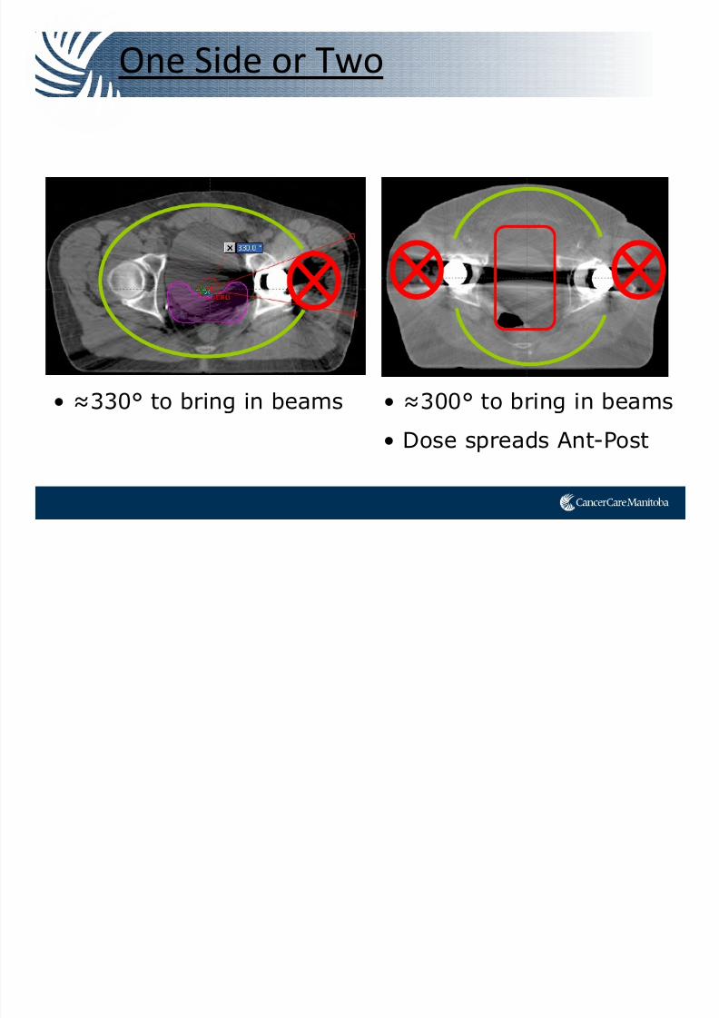
One Side or Two
• ≈330° to bring in beams • ≈300° to bring in beams
• Dose spreads Ant-Post
7/21/2019 Sutherland+PPT_Open Source
http://slidepdf.com/reader/full/sutherlandpptopen-source 33/91
What about IMRT / VMAT?
7/21/2019 Sutherland+PPT_Open Source
http://slidepdf.com/reader/full/sutherlandpptopen-source 34/91
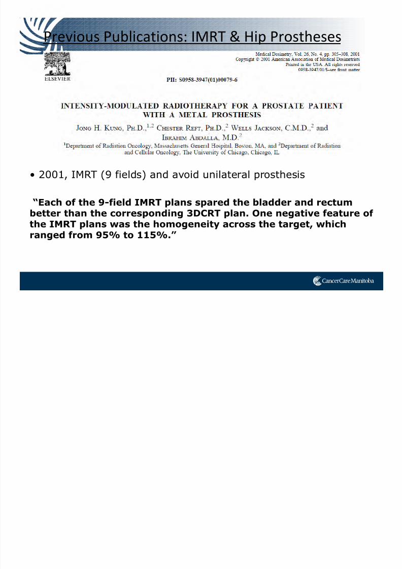
Previous Publications: IMRT & Hip Prostheses
• 2001, IMRT (9 fields) and avoid unilateral prosthesis
“Each of the 9-field IMRT plans spared the bladder and rectumbetter than the corresponding 3DCRT plan. One negative feature of
the IMRT plans was the homogeneity across the target, whichranged from 95% to 115%.”
7/21/2019 Sutherland+PPT_Open Source
http://slidepdf.com/reader/full/sutherlandpptopen-source 35/91
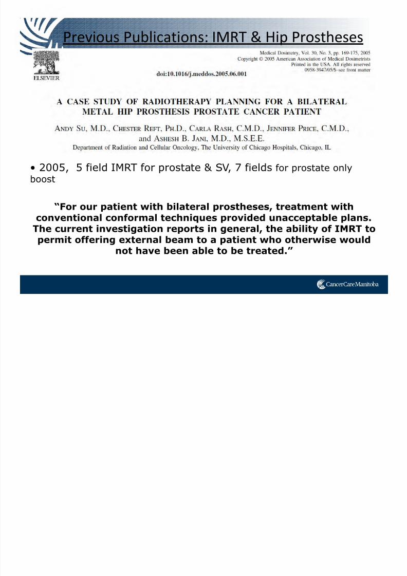
Previous Publications: IMRT & Hip Prostheses
• 2005, 5 field IMRT for prostate & SV, 7 fields for prostate onlyboost
“For our patient with bilateral prostheses, treatment withconventional conformal techniques provided unacceptable plans.
The current investigation reports in general, the ability of IMRT topermit offering external beam to a patient who otherwise would
not have been able to be treated.”
7/21/2019 Sutherland+PPT_Open Source
http://slidepdf.com/reader/full/sutherlandpptopen-source 36/91
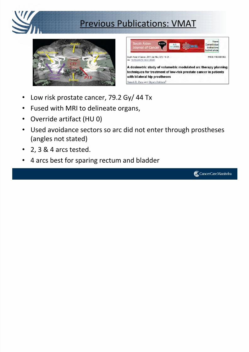
• Low risk prostate cancer, 79.2 Gy/ 44 Tx
• Fused with MRI to delineate organs,
• Override artifact (HU 0)
• Used avoidance sectors so arc did not enter through prostheses
(angles not stated)
• 2, 3 & 4 arcs tested.
• 4 arcs best for sparing rectum and bladder
Previous Publications: VMAT

7/21/2019 Sutherland+PPT_Open Source
http://slidepdf.com/reader/full/sutherlandpptopen-source 37/91
Case Study
7/21/2019 Sutherland+PPT_Open Source
http://slidepdf.com/reader/full/sutherlandpptopen-source 38/91
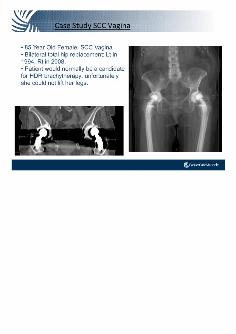
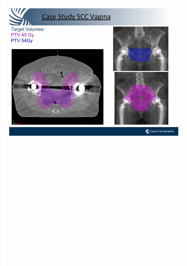
Case Study SCC Vagina
• 85 Year Old Female, SCC Vagina
• Bilateral total hip replacement: Lt in
1994, Rt in 2008.
• Patient would normally be a candidate
for HDR brachytherapy, unfortunately
she could not lift her legs.
7/21/2019 Sutherland+PPT_Open Source
http://slidepdf.com/reader/full/sutherlandpptopen-source 39/91
Case Study SCC Vagina
Target Volumes:PTV 45 Gy
PTV 54Gy
d i
7/21/2019 Sutherland+PPT_Open Source
http://slidepdf.com/reader/full/sutherlandpptopen-source 40/91
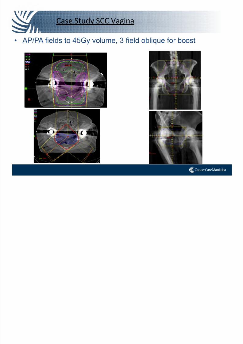
Case Study SCC Vagina
• AP/PA fields to 45Gy volume, 3 field oblique for boost
C S d SCC V i

7/21/2019 Sutherland+PPT_Open Source
http://slidepdf.com/reader/full/sutherlandpptopen-source 41/91
Case Study SCC Vagina
3DCRT - Sm Bowel, Rectum over tolerance. Bladder getting 100% dose.
PTV54GyPTV 45Gy
Bladder Rectum
Small Bowel
IMRT
7/21/2019 Sutherland+PPT_Open Source
http://slidepdf.com/reader/full/sutherlandpptopen-source 42/91
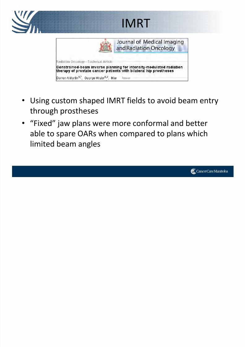
IMRT
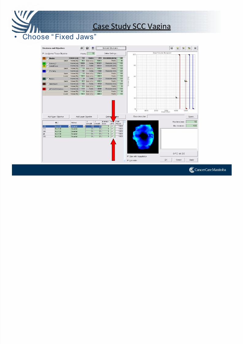
• Using custom shaped IMRT fields to avoid beam entry through prostheses
• “Fixed” jaw plans were more conformal and better
able to spare OARs when compared to plans which limited beam angles
7/21/2019 Sutherland+PPT_Open Source
http://slidepdf.com/reader/full/sutherlandpptopen-source 43/91
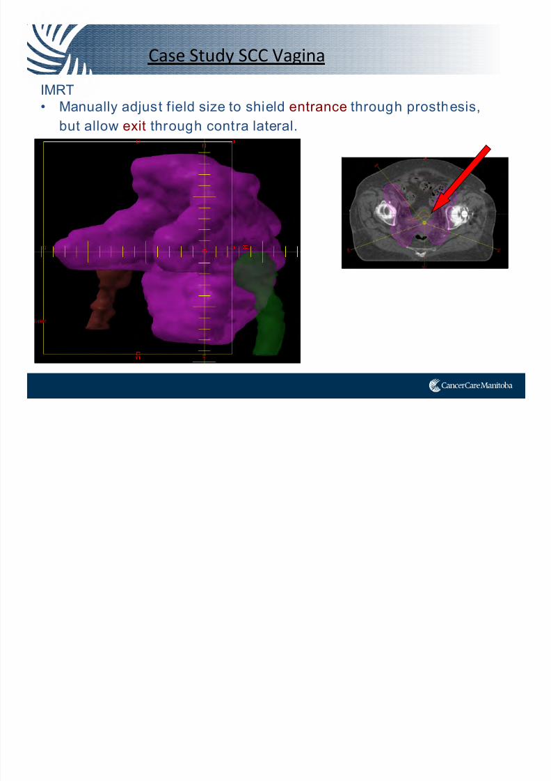
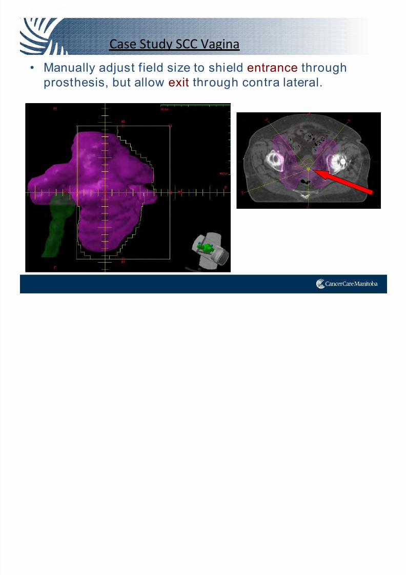
Case Study SCC Vagina
IMRT
• Manually adjust f ield size to shield entrance through prosthesis,
but allow exit through contra lateral.
7/21/2019 Sutherland+PPT_Open Source
http://slidepdf.com/reader/full/sutherlandpptopen-source 44/91
Case Study SCC Vagina
• Manually adjust field size to shield entrance through
prosthesis, but allow exit through contra lateral.
7/21/2019 Sutherland+PPT_Open Source
http://slidepdf.com/reader/full/sutherlandpptopen-source 45/91
Case Study SCC Vagina
• Choose “ Fixed Jaws”
Case Study SCC Vagina
7/21/2019 Sutherland+PPT_Open Source
http://slidepdf.com/reader/full/sutherlandpptopen-source 46/91
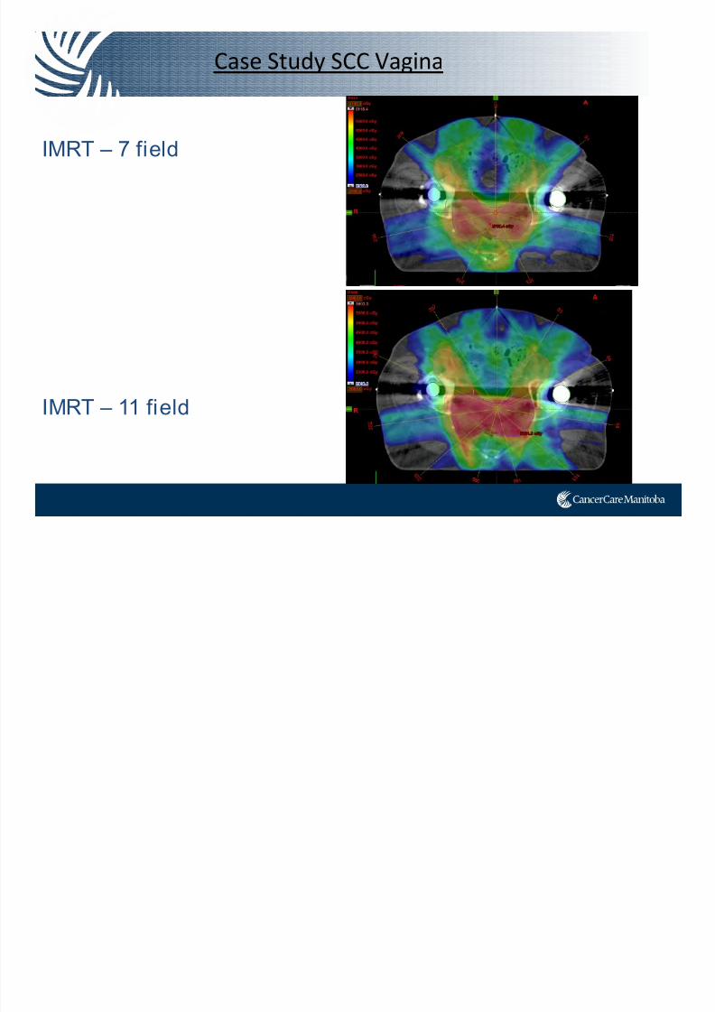
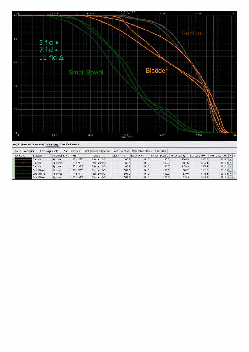
Case Study SCC Vagina
IMRT – 7 field
IMRT – 11 field
PTV 54Gy
7/21/2019 Sutherland+PPT_Open Source
http://slidepdf.com/reader/full/sutherlandpptopen-source 47/91
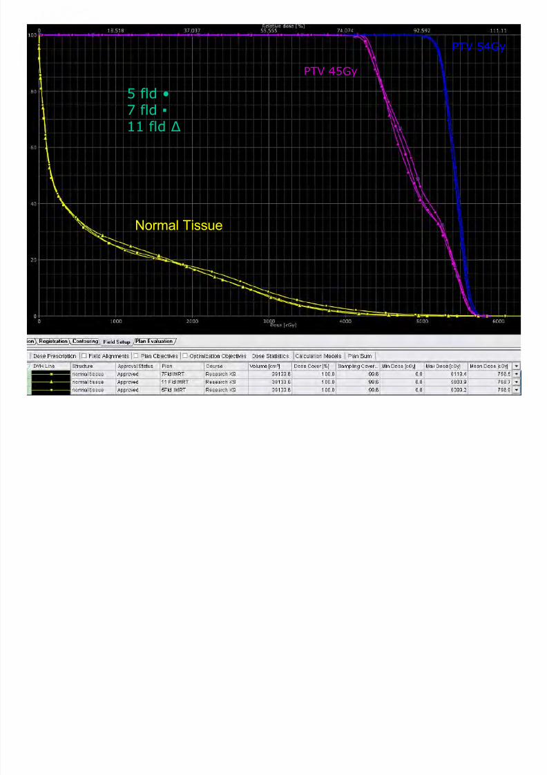
Normal Tissue
PTV 45Gy
PTV 54Gy
5 fld •7 fld ▪
11 fld Δ
7/21/2019 Sutherland+PPT_Open Source
http://slidepdf.com/reader/full/sutherlandpptopen-source 48/91
Small Bowel Bladder
Rectum
5 fld •7 fld ▪
11 fld Δ
7/21/2019 Sutherland+PPT_Open Source
http://slidepdf.com/reader/full/sutherlandpptopen-source 49/91
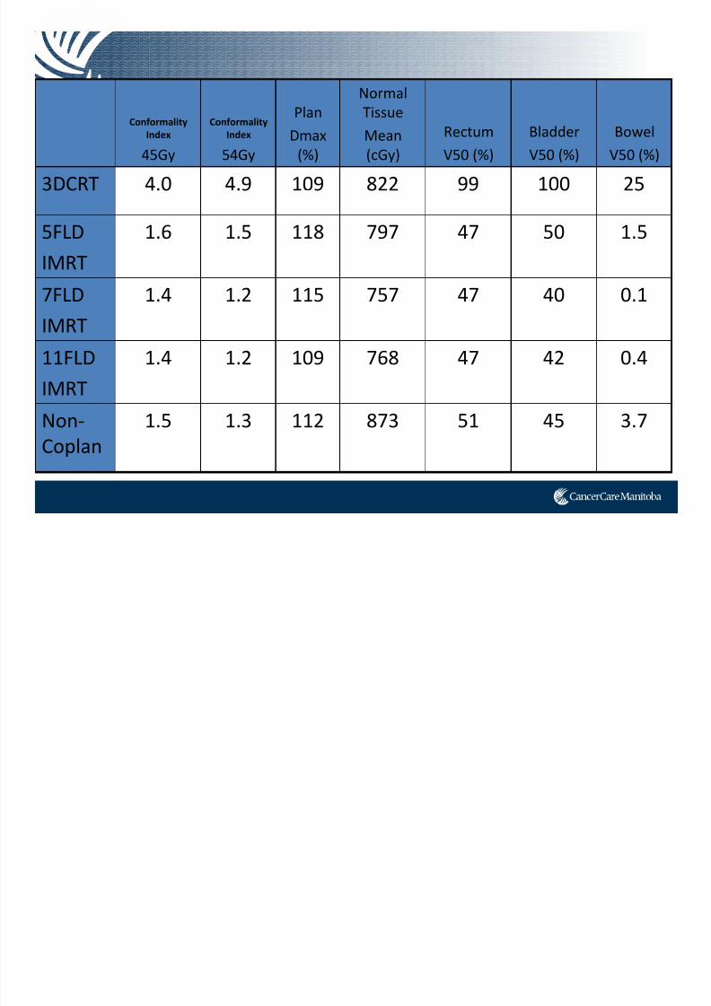
Conformality
Index
45Gy
Conformality
Index
54Gy
Plan
Dmax
(%)
Normal
Tissue
Mean
(cGy)
Rectum
V50 (%)
Bladder
V50 (%)
Bowel
V50 (%)
3DCRT 4.0 4.9 109 822 99 100 25
5FLD
IMRT
1.6 1.5 118 797 47 50 1.5
7FLD IMRT
1.4 1.2 115 757 47 40 0.1
11FLD
IMRT
1.4 1.2 109 768 47 42 0.4
Non‐
Coplan
1.5 1.3 112 873 51 45 3.7
VMAT
7/21/2019 Sutherland+PPT_Open Source
http://slidepdf.com/reader/full/sutherlandpptopen-source 50/91
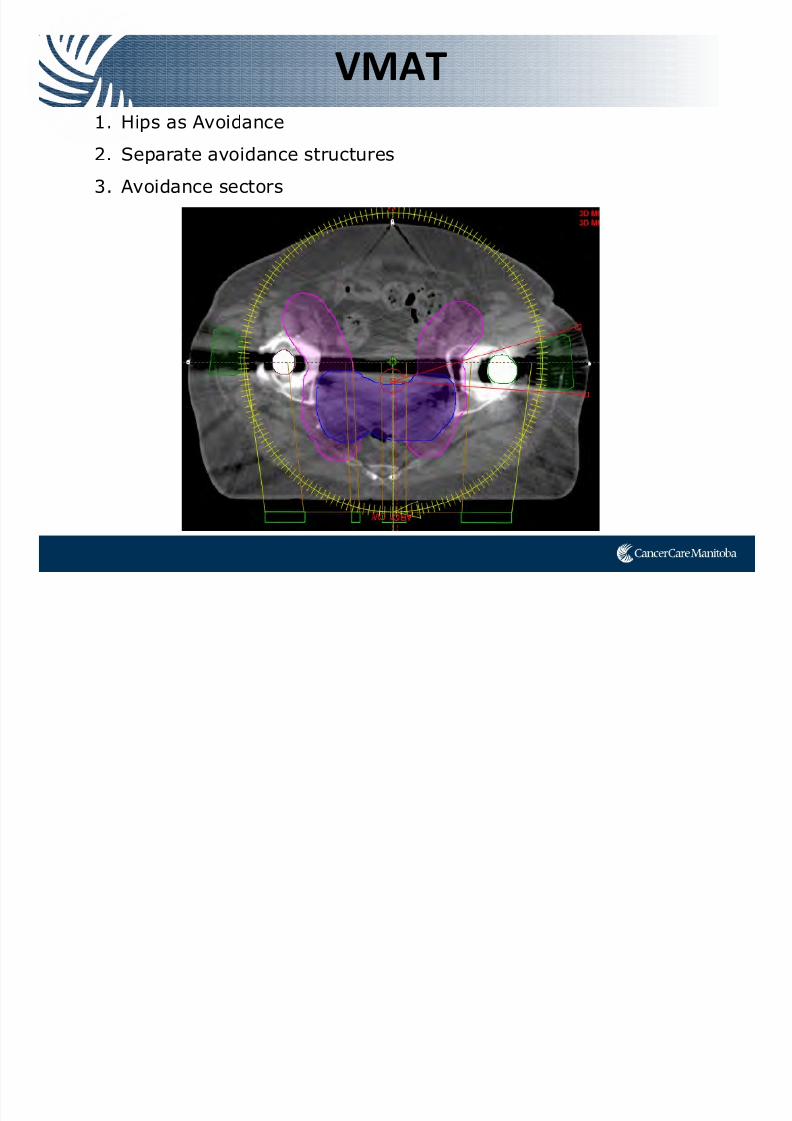
VMAT
1. Hips as Avoidance
2. Separate avoidance structures
3. Avoidance sectors
Case Study SCC Vagina
7/21/2019 Sutherland+PPT_Open Source
http://slidepdf.com/reader/full/sutherlandpptopen-source 51/91
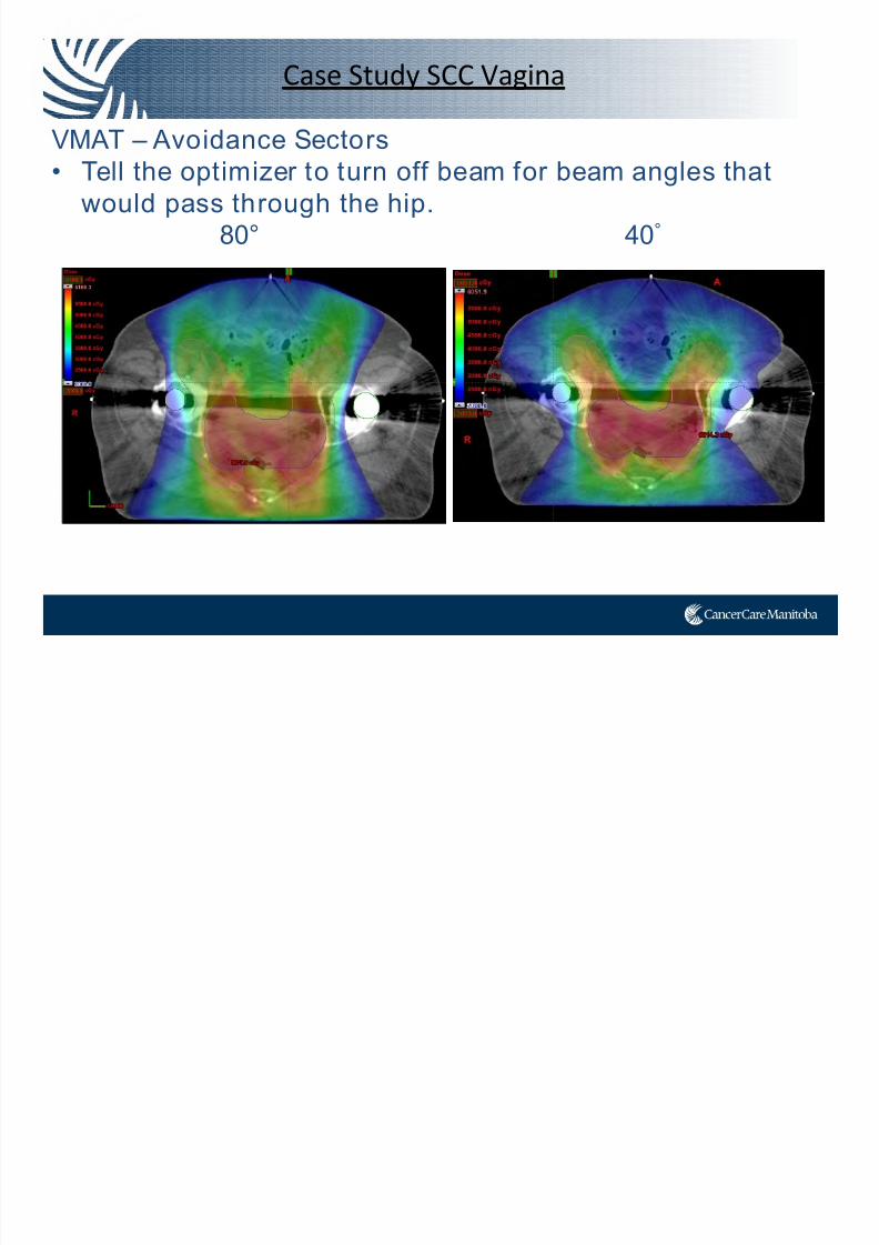
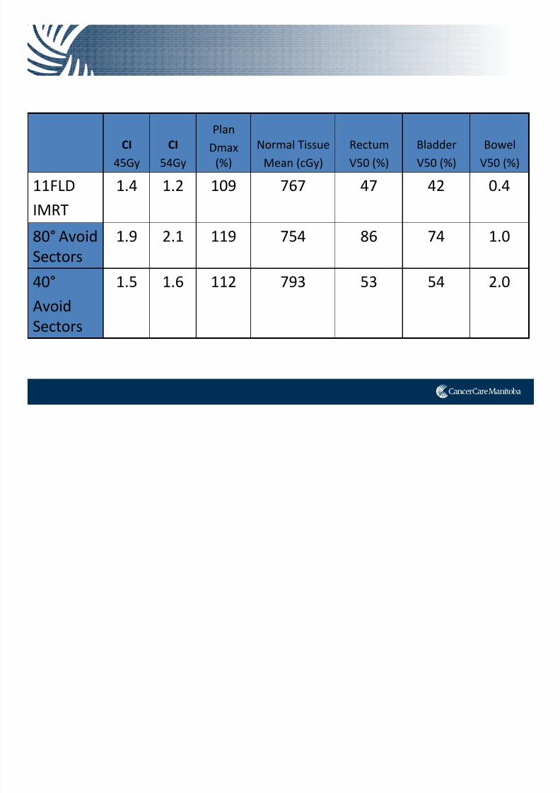
Case Study SCC Vagina
VMAT – Avoidance Sectors• Tell the optimizer to turn off beam for beam angles that
would pass through the hip.
80° 40°
7/21/2019 Sutherland+PPT_Open Source
http://slidepdf.com/reader/full/sutherlandpptopen-source 52/91
CI
45Gy
CI
54Gy
Plan
Dmax
(%)
Normal Tissue
Mean (cGy)
Rectum
V50 (%)
Bladder
V50 (%)
Bowel
V50 (%)
11FLD
IMRT
1.4 1.2 109 767 47 42 0.4
80° Avoid Sectors
1.9 2.1 119 754 86 74 1.0
40°
Avoid Sectors
1.5 1.6 112 793 53 54 2.0

7/21/2019 Sutherland+PPT_Open Source
http://slidepdf.com/reader/full/sutherlandpptopen-source 53/91
Prostate Bed
Case Study Prostate Bed
7/21/2019 Sutherland+PPT_Open Source
http://slidepdf.com/reader/full/sutherlandpptopen-source 54/91
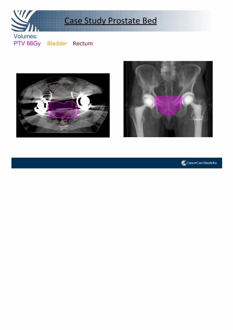
Case Study Prostate Bed
Volumes:PTV 66Gy Bladder Rectum
Case Study Prostate Bed
7/21/2019 Sutherland+PPT_Open Source
http://slidepdf.com/reader/full/sutherlandpptopen-source 55/91
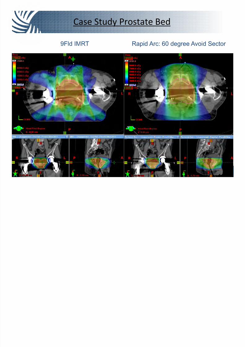
y
9Fld IMRT Rapid Arc: 60 degree Avoid Sector
Case Study Prostate Bed
7/21/2019 Sutherland+PPT_Open Source
http://slidepdf.com/reader/full/sutherlandpptopen-source 56/91
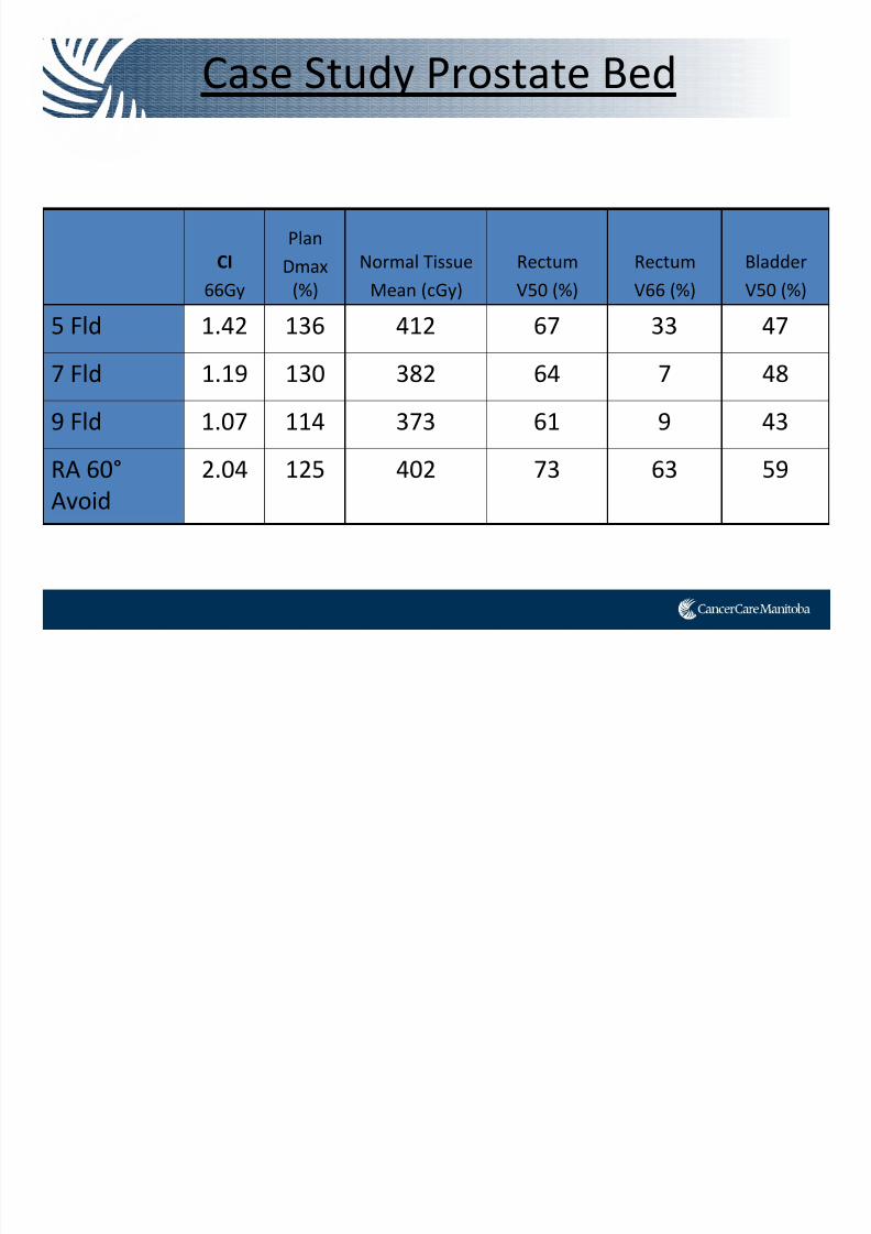
CI
66Gy
Plan
Dmax
(%)
Normal Tissue
Mean (cGy)
Rectum
V50 (%)
Rectum
V66 (%)
Bladder
V50 (%)
5 Fld 1.42 136 412 67 33 47
7 Fld 1.19 130 382 64 7 48
9 Fld 1.07 114 373 61 9 43
RA 60°
Avoid
2.04 125 402 73 63 59
y
However…
7/21/2019 Sutherland+PPT_Open Source
http://slidepdf.com/reader/full/sutherlandpptopen-source 57/91
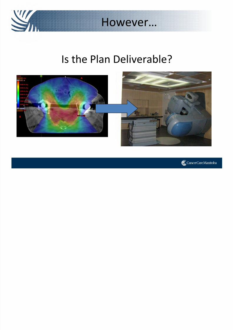
However…
Is the Plan Deliverable?
Cancer Care Manitoba Research

7/21/2019 Sutherland+PPT_Open Source
http://slidepdf.com/reader/full/sutherlandpptopen-source 58/91
Research Project
7/21/2019 Sutherland+PPT_Open Source
http://slidepdf.com/reader/full/sutherlandpptopen-source 59/91
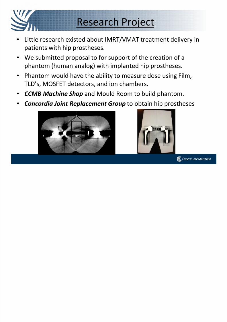
Research Project
• Little research existed about IMRT/VMAT treatment delivery in
patients with hip prostheses.
• We submitted proposal to for support of the creation of a
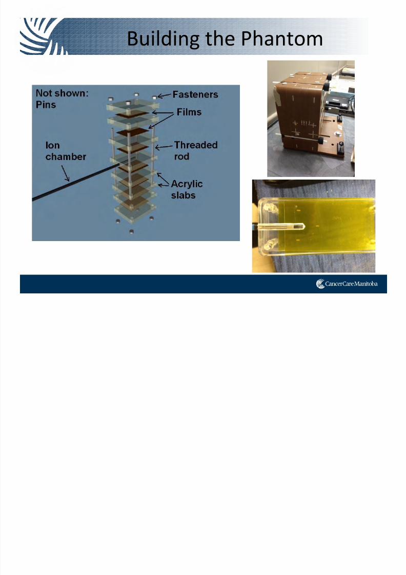
phantom (human analog) with implanted hip prostheses.• Phantom would have the ability to measure dose using Film,
TLD’s, MOSFET detectors, and ion chambers.
• CCMB
Machine
Shop and Mould
Room
to build
phantom.
• Concordia Joint Replacement Group to obtain hip prostheses
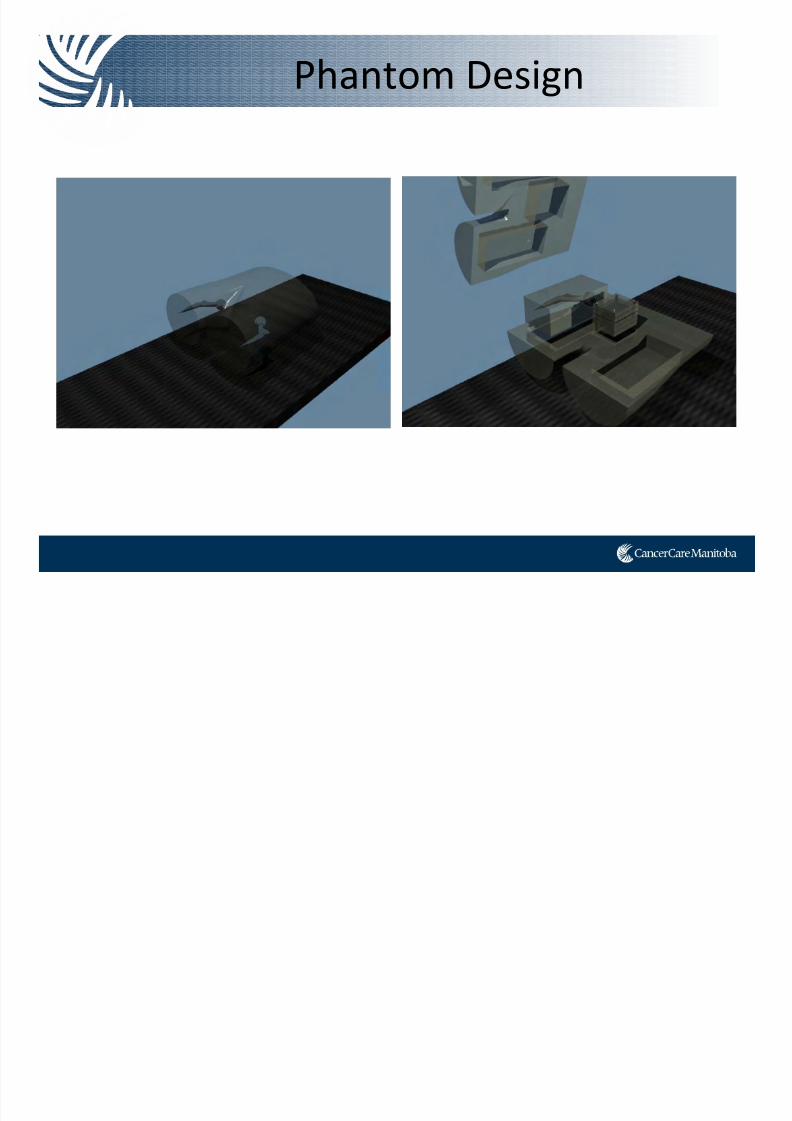
Phantom Design
7/21/2019 Sutherland+PPT_Open Source
http://slidepdf.com/reader/full/sutherlandpptopen-source 60/91
g
Building the Phantom
7/21/2019 Sutherland+PPT_Open Source
http://slidepdf.com/reader/full/sutherlandpptopen-source 61/91
g
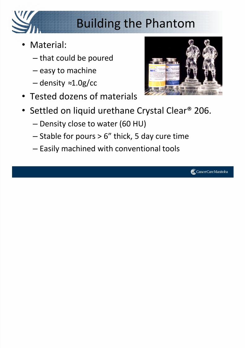
• Material:
– that could be poured
– easy to machine – density ≈1.0g/cc
• Tested dozens of materials
• Settled on liquid urethane Crystal Clear® 206.
– Density close to water (60 HU)
– Stable for pours > 6” thick, 5 day cure time – Easily machined with conventional tools
Building the Phantom
7/21/2019 Sutherland+PPT_Open Source
http://slidepdf.com/reader/full/sutherlandpptopen-source 62/91
g
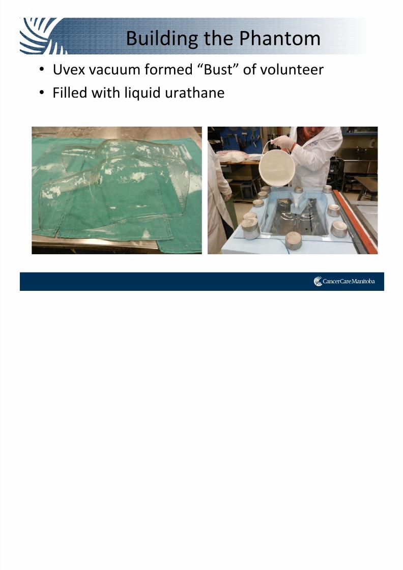
• Uvex vacuum formed “Bust” of volunteer
• Filled with liquid urathane
Building the Phantom
7/21/2019 Sutherland+PPT_Open Source
http://slidepdf.com/reader/full/sutherlandpptopen-source 63/91
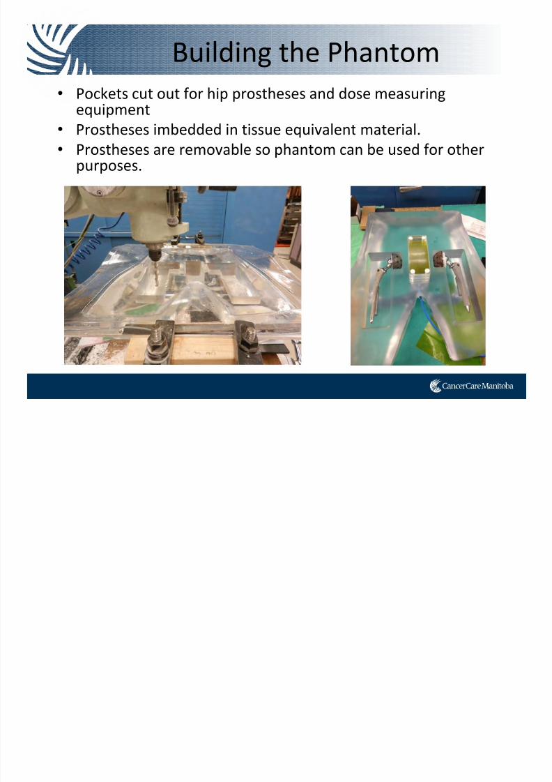
• Pockets cut out for hip prostheses and dose measuring equipment
• Prostheses imbedded in tissue equivalent material.
• Prostheses are removable so phantom can be used for other purposes.
g
Building the Phantom
7/21/2019 Sutherland+PPT_Open Source
http://slidepdf.com/reader/full/sutherlandpptopen-source 64/91
g
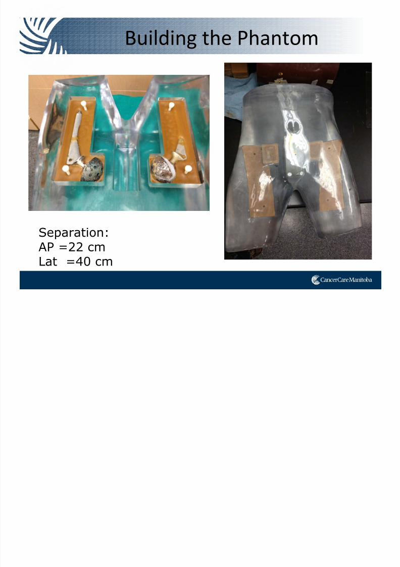
Separation:AP =22 cmLat =40 cm
Building the Phantom
7/21/2019 Sutherland+PPT_Open Source
http://slidepdf.com/reader/full/sutherlandpptopen-source 65/91
Experiments

7/21/2019 Sutherland+PPT_Open Source
http://slidepdf.com/reader/full/sutherlandpptopen-source 66/91
• Phantom scanned on a CT
Simulator
• Various VMAT plans attempted in Eclipse (V.10, AAA algorithm)
• Various tissue overrides
attempted • Deliverability of plans verified
with ion chamber and film in the
phantom
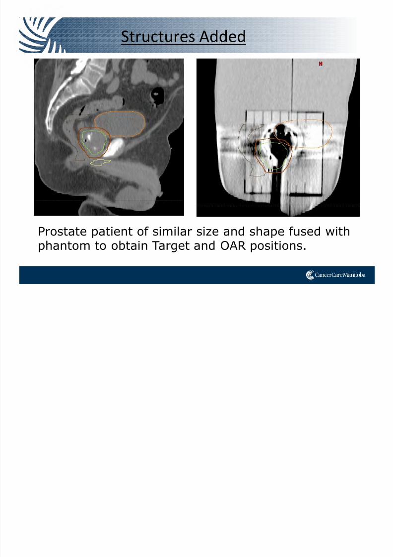
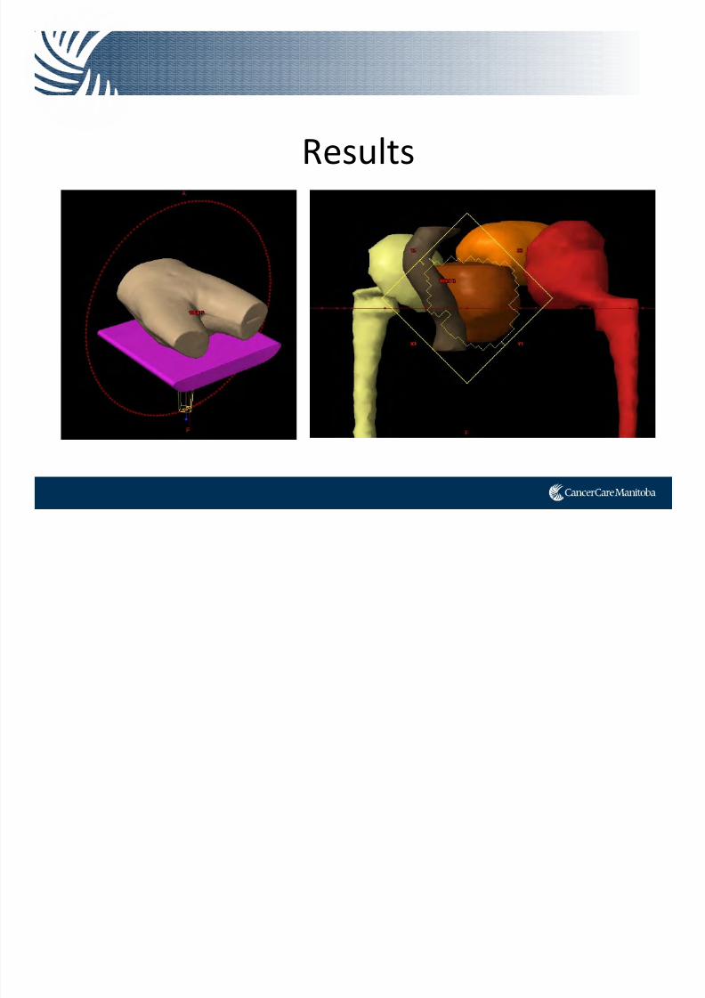
Structures Added
7/21/2019 Sutherland+PPT_Open Source
http://slidepdf.com/reader/full/sutherlandpptopen-source 67/91
Prostate patient of similar size and shape fused withphantom to obtain Target and OAR positions.
7/21/2019 Sutherland+PPT_Open Source
http://slidepdf.com/reader/full/sutherlandpptopen-source 68/91
Challenges
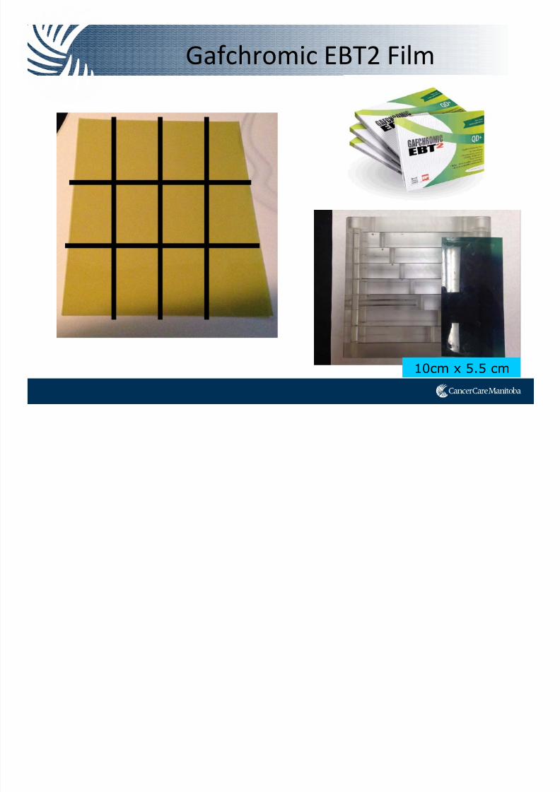
Gafchromic EBT2 Film
7/21/2019 Sutherland+PPT_Open Source
http://slidepdf.com/reader/full/sutherlandpptopen-source 69/91
10cm x 5.5 cm
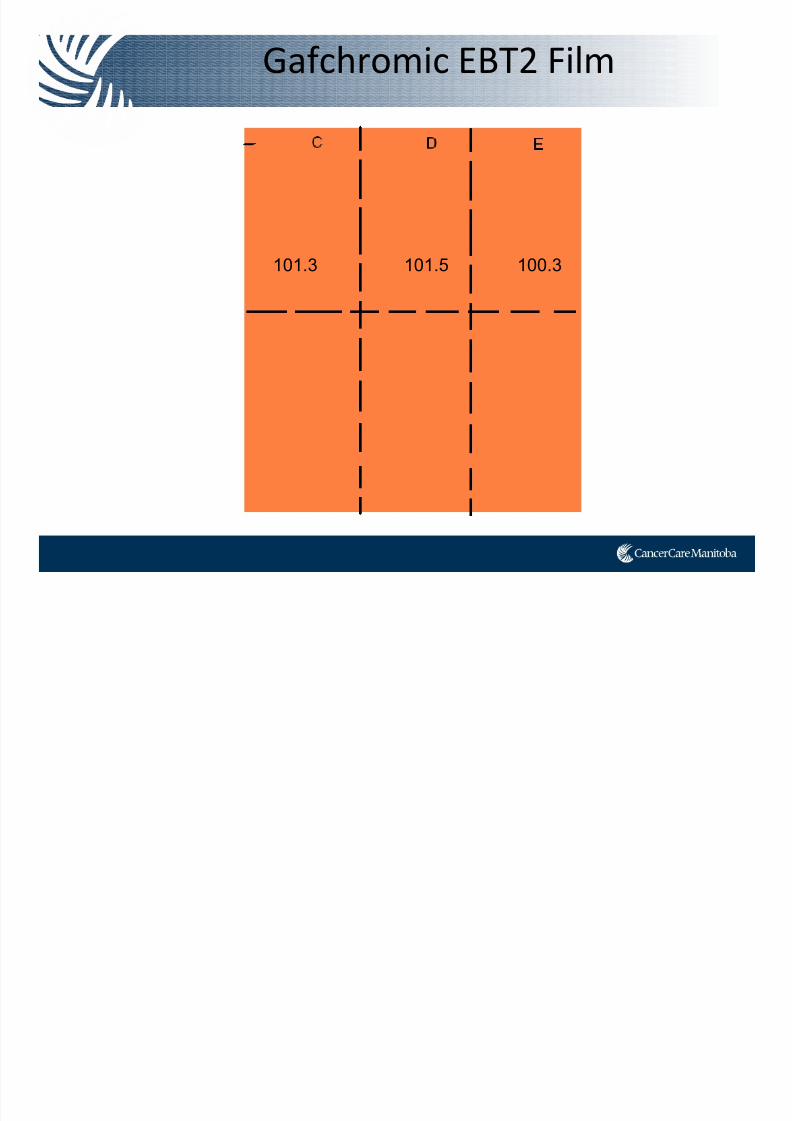
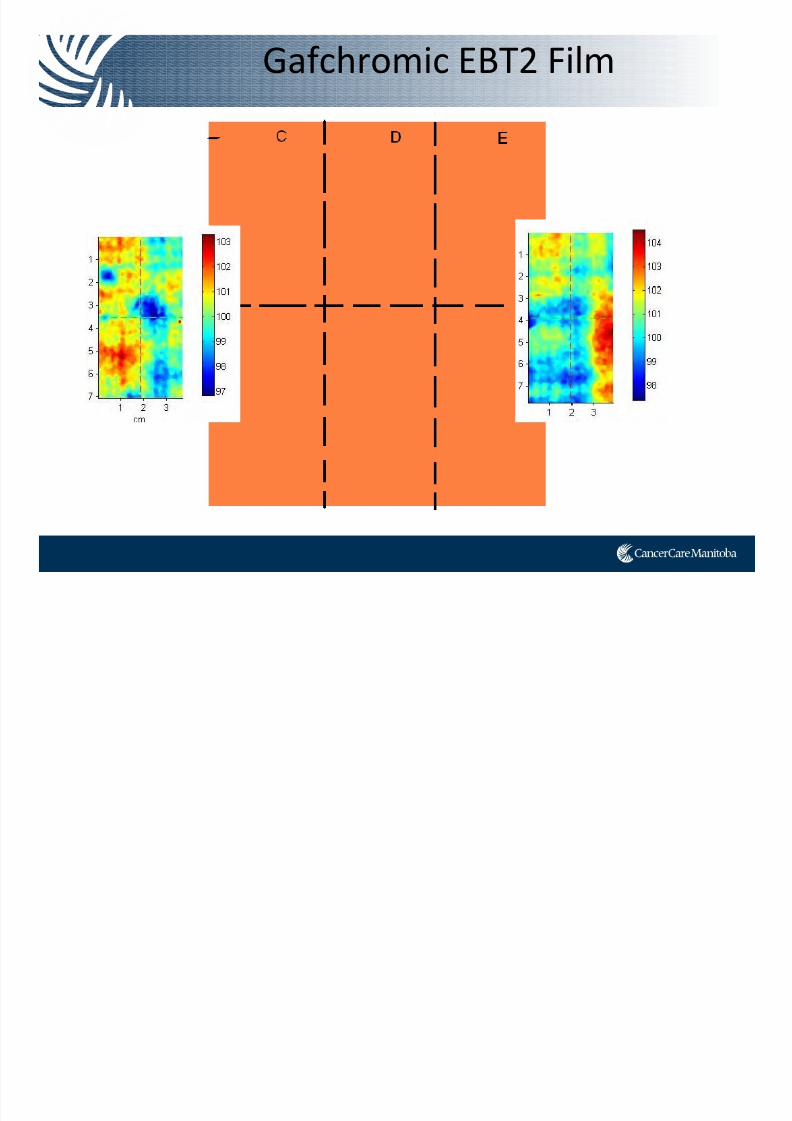
Gafchromic EBT2 Film
7/21/2019 Sutherland+PPT_Open Source
http://slidepdf.com/reader/full/sutherlandpptopen-source 70/91
101.3 101.5 100.3
Gafchromic EBT2 Film
7/21/2019 Sutherland+PPT_Open Source
http://slidepdf.com/reader/full/sutherlandpptopen-source 71/91
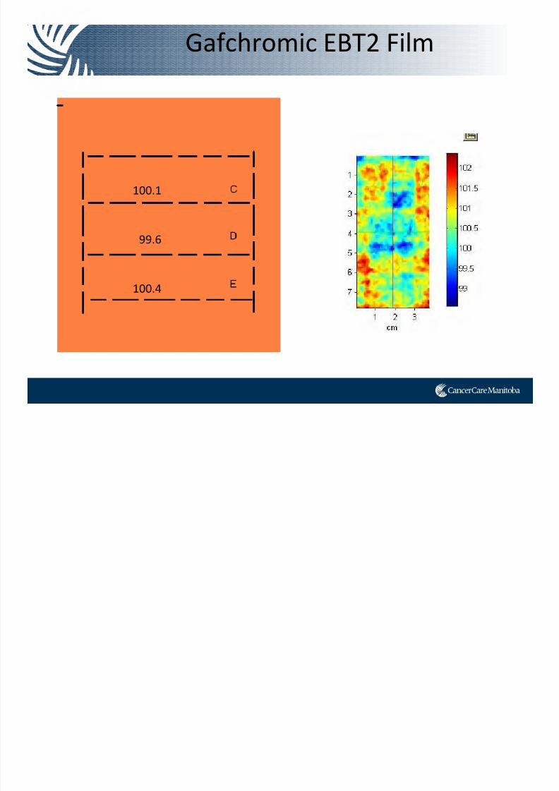
Gafchromic EBT2 Film
7/21/2019 Sutherland+PPT_Open Source
http://slidepdf.com/reader/full/sutherlandpptopen-source 72/91
100.1
99.6
100.4
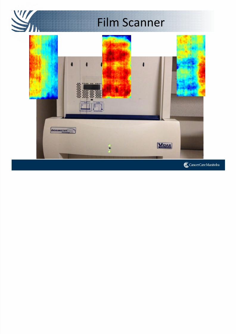
Film Scanner
7/21/2019 Sutherland+PPT_Open Source
http://slidepdf.com/reader/full/sutherlandpptopen-source 73/91
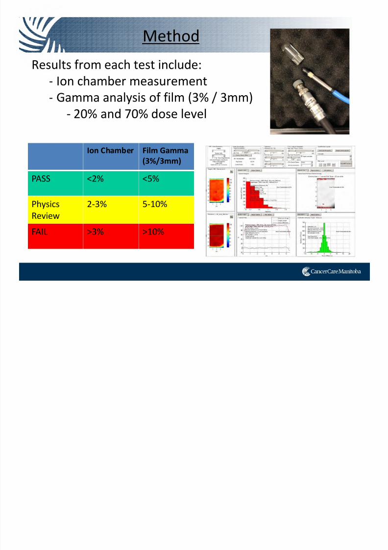
Method
7/21/2019 Sutherland+PPT_Open Source
http://slidepdf.com/reader/full/sutherlandpptopen-source 74/91
Results from each test include:‐ Ion chamber measurement
‐ Gamma analysis of film (3% / 3mm)
‐ 20% and 70% dose level
Ion Chamber Film Gamma
(3%/3mm)
PASS <2% <5%
Physics
Review
2‐3% 5‐10%
FAIL >3% >10%
7/21/2019 Sutherland+PPT_Open Source
http://slidepdf.com/reader/full/sutherlandpptopen-source 75/91
Results
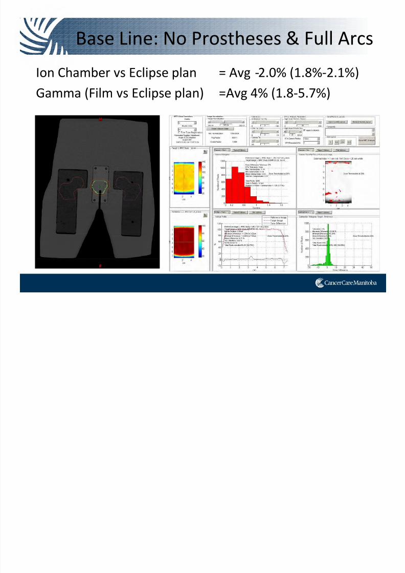
Base Line: No Prostheses & Full Arcs
7/21/2019 Sutherland+PPT_Open Source
http://slidepdf.com/reader/full/sutherlandpptopen-source 76/91
Ion Chamber vs Eclipse plan = Avg ‐2.0% (1.8%‐2.1%)
Gamma (Film vs Eclipse plan) =Avg 4% (1.8‐5.7%)
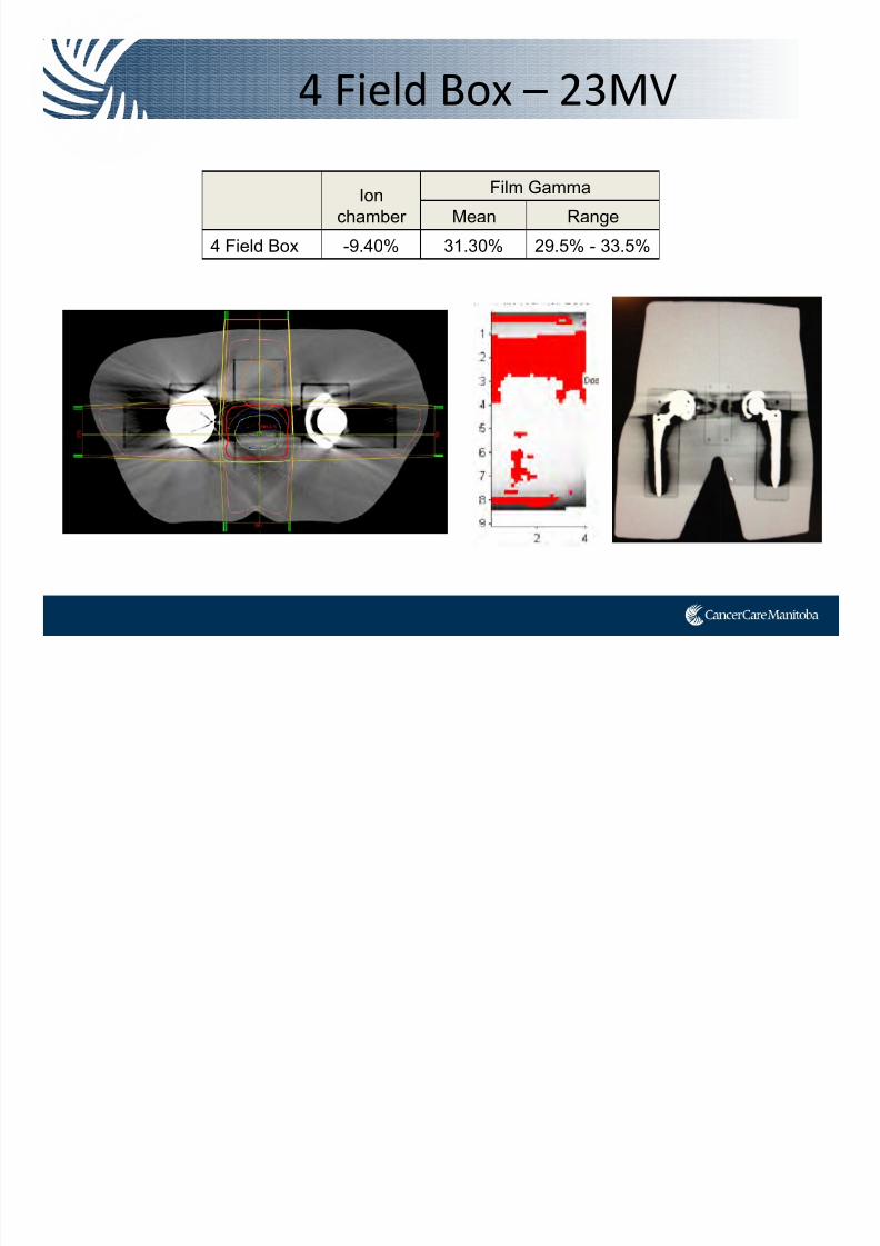
4 Field Box – 23MV
7/21/2019 Sutherland+PPT_Open Source
http://slidepdf.com/reader/full/sutherlandpptopen-source 77/91
Ion
chamber
Film Gamma
Mean Range
4 Field Box -9.40% 31.30% 29.5% - 33.5%
Density Override?

7/21/2019 Sutherland+PPT_Open Source
http://slidepdf.com/reader/full/sutherlandpptopen-source 78/91
No Override
Low Density Override
(-1000 to -150 HU)
Low and High Override
(150 to 3000 HU)
Density Override?

7/21/2019 Sutherland+PPT_Open Source
http://slidepdf.com/reader/full/sutherlandpptopen-source 79/91
Ion
Chamber
Film Gamma
(6 films analyzed)
Mean Range
No Density
Override -2.20% 6.11% 1.5% - 7.7%
Low Density
only -0.99% 4.86% 0.1% - 5.5%
Low and
High DensityOverride 0.29% 3.73% 0.5% - 7.2%
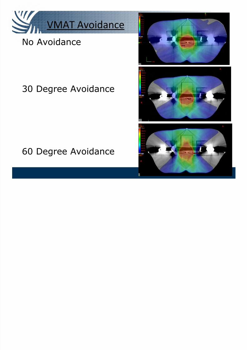
VMAT Avoidance
7/21/2019 Sutherland+PPT_Open Source
http://slidepdf.com/reader/full/sutherlandpptopen-source 80/91
No Avoidance
30 Degree Avoidance
60 Degree Avoidance
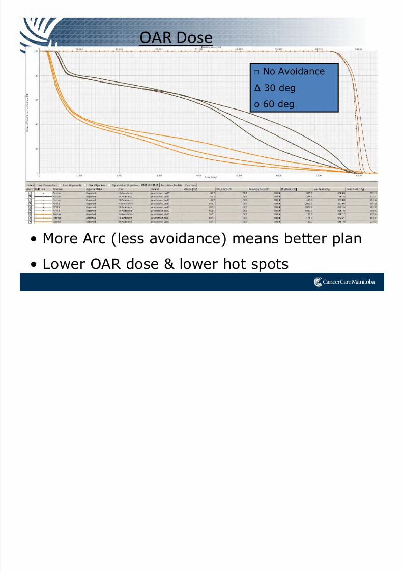
OAR Dose
7/21/2019 Sutherland+PPT_Open Source
http://slidepdf.com/reader/full/sutherlandpptopen-source 81/91
• More Arc (less avoidance) means better plan
• Lower OAR dose & lower hot spots
□ No Avoidance
∆ 30 deg
o 60 deg
Ion Chamber Results

7/21/2019 Sutherland+PPT_Open Source
http://slidepdf.com/reader/full/sutherlandpptopen-source 82/91
Ion Chamber Dose vs Eclipse Dose
-5.0%
-4.0%
-3.0%
-2.0%
-1.0%
0.0%
1.0%
1 2 3 4 5
Run #
% D
i v v e r e n c e
Noavoidance
30 degavoid
60 degavoid
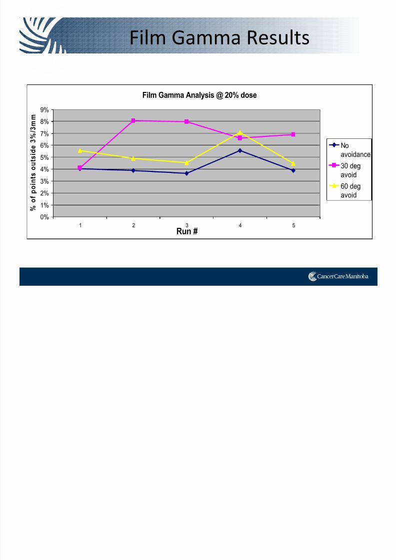
Film Gamma Results
7/21/2019 Sutherland+PPT_Open Source
http://slidepdf.com/reader/full/sutherlandpptopen-source 83/91
Film Gamma Analysis @ 20% dose
0%
1%
2%
3%
4%
5%
6%
7%
8%
9%
1 2 3 4 5Run #
% o
f p o i n t s o u t s i d e 3 % / 3 m m
No
avoidance
30 deg
avoid
60 deg
avoid
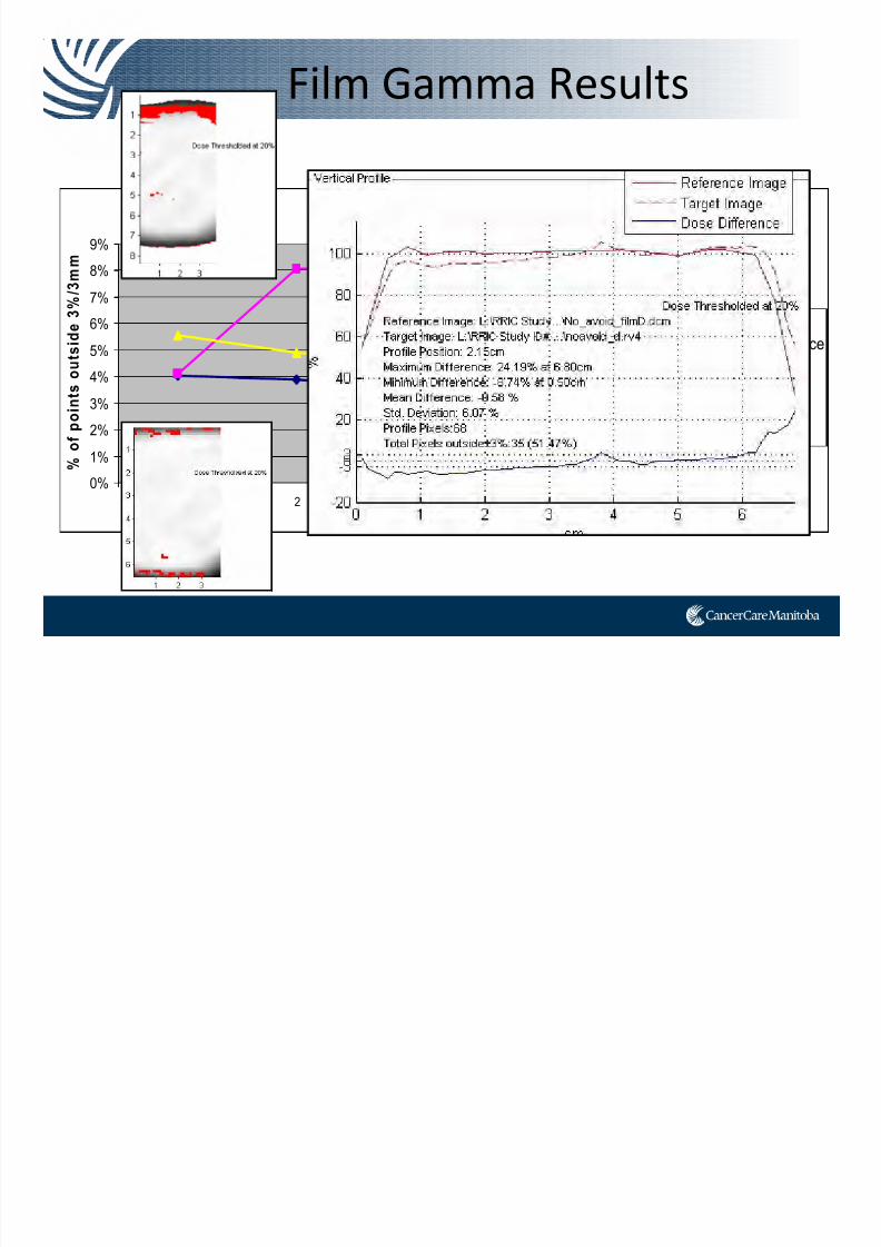
Film Gamma Results
7/21/2019 Sutherland+PPT_Open Source
http://slidepdf.com/reader/full/sutherlandpptopen-source 84/91
Film Gamma Analysis @ 20% dose
0%
1%
2%
3%4%
5%
6%
7%
8%
9%
1 2 3 4 5Run #
% o
f p o i n t s o u t s i d e 3 % / 3 m m
No
avoidance
30 deg
avoid
60 deg
avoid
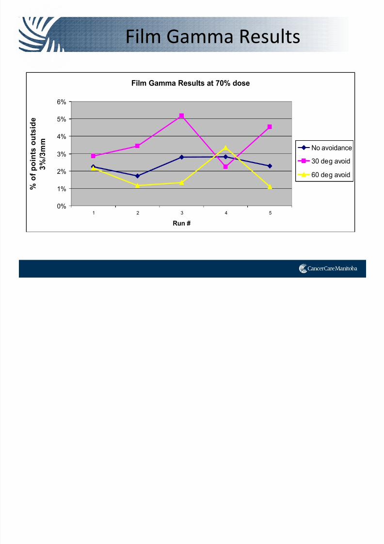
Film Gamma Results
7/21/2019 Sutherland+PPT_Open Source
http://slidepdf.com/reader/full/sutherlandpptopen-source 85/91
Film Gamma Results at 70% dose
0%
1%
2%
3%
4%
5%
6%
1 2 3 4 5
Run #
% o
f p o
i n t s o u t s i d e
3 % / 3 m m
No avoidance
30 deg avoid
60 deg avoid
Summary
7/21/2019 Sutherland+PPT_Open Source
http://slidepdf.com/reader/full/sutherlandpptopen-source 86/91
• All of our plans independently passed our COMPASS QA, however 60 degree avoidance sectors were closed to failing.
– More modulation = less deliverable plans?
• Our preliminary data shows that large avoidance sectors in VMAT planning do not necessarily = more deliverable plan.
• Even though our results using the phantom are inconsistent,
plans either pass or are close to passing our film QA criteria.
• Future:
– Try breaking the arcs up…3 partial arcs instead on avoidance
– Try EBT3 film
– Try MOSFET detectors
So what’s going on?

7/21/2019 Sutherland+PPT_Open Source
http://slidepdf.com/reader/full/sutherlandpptopen-source 87/91
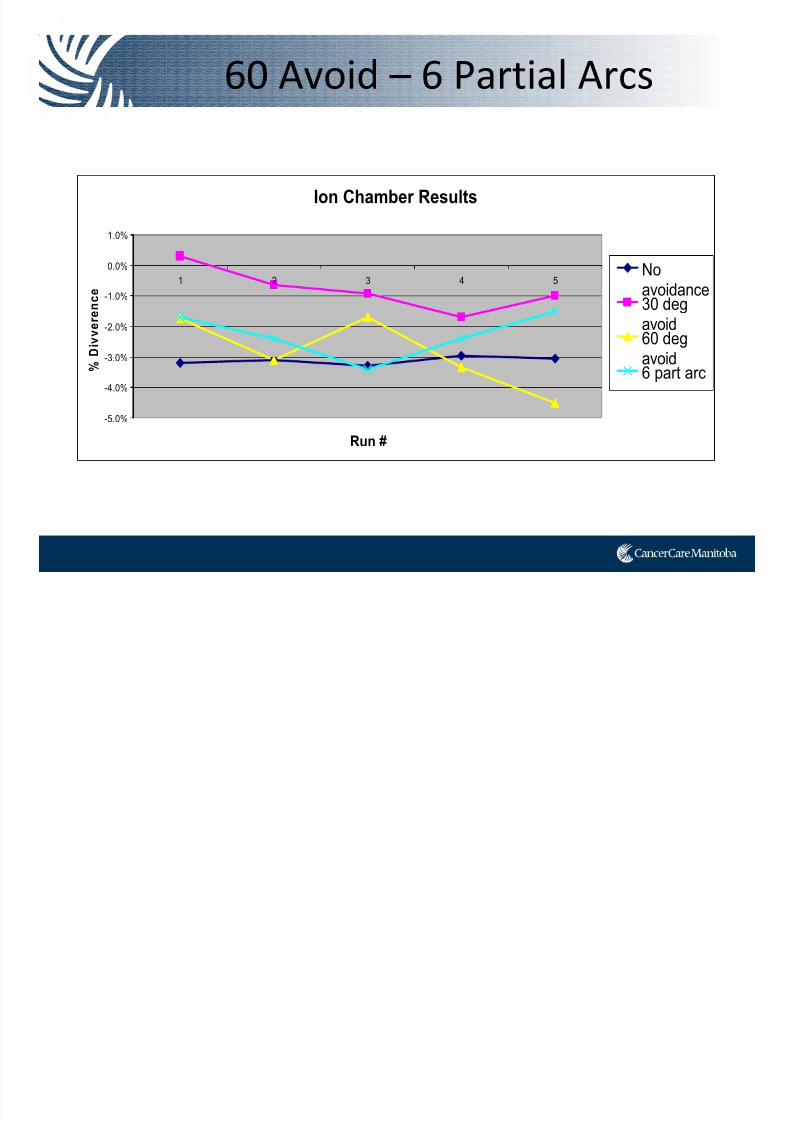
• Are the avoidance sectors degrading plan quality? (<control points? more modulation?)
• 3 partial arcs (181‐240, 300‐60, 120‐179)
60 Avoid – 6 Partial Arcs
7/21/2019 Sutherland+PPT_Open Source
http://slidepdf.com/reader/full/sutherlandpptopen-source 88/91
Ion Chamber Results
-5.0%
-4.0%
-3.0%
-2.0%
-1.0%
0.0%
1.0%
1 2 3 4 5
Run #
% D i v
v e r e n c e
Noavoidance30 degavoid
60 degavoid6 part arc
60 Avoid – 6 Partial Arcs

7/21/2019 Sutherland+PPT_Open Source
http://slidepdf.com/reader/full/sutherlandpptopen-source 89/91
Film Gamma Analysis @ 20% dose
0%
1%
2%
3%
4%
5%
6%
7%
8%
9%
1 2 3 4 5
Run #
% o
f p o i n t s o u t s i d e 3 % / 3 m m
No
avoidance30 deg
avoid
60 degavoid6 Part arc
Conclusions
Hi th b i i ti t
7/21/2019 Sutherland+PPT_Open Source
http://slidepdf.com/reader/full/sutherlandpptopen-source 90/91
• Hip prostheses are becoming more common in patientswith pelvic cancers.
• Traditionally treatment through hip prosthesis is not
advised due to inability to accurately calculate dose.
• Treatment with IMRT or VMAT is technically possible,
and yields plans of reasonable quality
• Our phantom research shows that avoidance sectors
that do not completely avoid the prostheses seem asdeliverable as plans with 30 degree and 60 degree
avoidance sectors.
• Small or no avoidance = <OAR dose
• More research is required to conclude what technique
best balances deliverabil ity and OAR sparing.

7/21/2019 Sutherland+PPT_Open Source
http://slidepdf.com/reader/full/sutherlandpptopen-source 91/91