sustainability and flexural behaviour of textile...
TRANSCRIPT

THESIS FOR THE DEGREE OF LICENTIATE OF ENGINEERING
Sustainability and Flexural Behaviour of Textile Reinforced Concrete NATALIE WILLIAMS PORTAL
Department of Civil and Environmental Engineering Division of Structural Engineering
Concrete Structures CHALMERS UNIVERSITY OF TECHNOLOGY
Gothenburg, Sweden 2013
Sustainability and Flexural Behaviour of Textile Reinforced Concrete
NATALIE WILLIAMS PORTAL ISBN 978-91-7385-552-5
© NATALIE WILLIAMS PORTAL, 2013
ISSN no. 1652-9146 Lic 2013:9 Department of Civil and Environmental Engineering Division of Structural Engineering, Concrete Structures Chalmers University of Technology SE-412 96 Gothenburg Sweden Telephone: + 46 (0)31-772 1000 Cover: The fundamental components included in Textile Reinforced Concrete are illustrated (top-bottom): carbon filament yarns, carbon woven 2D mesh and composite form with fine-grained concrete. Photos: author and Danish Technical Institute. Chalmers Repro Service / Department of Civil and Environmental Engineering Gothenburg, Sweden, 2013

I
Sustainability and Flexural Behaviour of Textile Reinforced Concrete
NATALIE WILLIAMS PORTAL
Department of Civil and Environmental Engineering Division of Structural Engineering, Concrete Structures Chalmers University of Technology
ABSTRACT Concrete reinforced with conventional steel is one of the most commonly used building materials, yet it has historically shown disadvantages in terms of durability and vulnerability to corrosion attack. Various remedial methods have been applied to overcome the shortcomings of this building material, such as increasing the concrete cover, which, however, leads to an increased self-weight of the structure. Over the past decade, Textile Reinforced Concrete (TRC), encompassing a combination of fine-grained concrete and non-corrosive multi-axial textile fabrics, has emerged as a promising novel alternative offering corrosion resistance, as well as thinner and light-weight structures such as foot bridges and façade elements.
This thesis aims to preliminarily investigate the sustainability and flexural behaviour of TRC while bearing in mind its possible use for future buildings. The sustainable potential of TRC was evaluated using Life Cycle Assessment (LCA) with a cradle-to-gate perspective, such that conventional steel reinforced concrete and TRC were compared. It was revealed that TRC significantly decreased the cumulative energy demand and environmental impact of a reinforced concrete element; basalt fibre reinforcement yielded the least cumulative energy demand while carbon fibre gave the least environmental impact. Using TRC in the form of sandwich panels was also shown to yield a lower environmental impact compared to conventional reinforced concrete panels.
Moreover, experimental studies were conducted to investigate the load-carrying capacity in bending and overall structural behaviour of TRC in both one-way and two-way action. It could be concluded that one-way slabs reinforced by one layer of carbon textile mesh had superior load-carrying capacity and ductility in comparison to specimens reinforced by one layer of alkali-resistant glass or basalt. The testing of two-way slabs demonstrated that among basalt and AR-glass reinforced specimens, basalt had a slightly higher flexural capacity. Furthermore, a 2D non-linear finite element model developed based on the one-way experiments, correlated rather well with the experimental results after calibration. Lastly, analytical calculation methods developed for conventionally reinforced concrete structures were used to evaluate the experimental results. The analytical results were shown to both under and over predict the flexural capacity in one-way and two-way action.
Overall, experimental studies encompassing a greater study sample, optimized reinforcement ratios and application of fibre coatings are recommended to obtain further enhanced performance. The experimental programs, presented in this thesis, are valuable as they contribute to the expansion of fundamental knowledge related to TRC while promoting the prospective use of this novel material.
Keywords: Textile Reinforced Concrete (TRC), sustainability, flexural behaviour, Life Cycle Assessment (LCA), façade elements, one-way action, two-way action, structural tests, non-linear finite element analyses.

II

III
LIST OF PUBLICATIONS
This thesis consists of an extended summary and the following appended papers:
Paper I Williams Portal, N., Lundgren, K., Walter, A.M., Frederiksen, J.O. and Nyholm Thrane, L. (2012): Numerical Modelling of Textile Reinforced Concrete. Published In: Proceedings of VIII International Conference on Fracture Mechanics of Concrete and Concrete Structures, March 2013, Toledo, Spain (Peer reviewed).
Paper II Williams Portal, N., Lundgren, K., Wallbaum, H. and Malaga K. (2013): Sustainable Potential of Textile-Reinforced Concrete (TRC). Submitted for publication to American Society of Civil Engineers (ASCE) Materials in Civil Engineering.
Paper III Williams Portal, N., Nyholm Thrane, L., Lundgren, K. and Fall, D. (2013): Flexural Behaviour of Textile Reinforced Concrete (TRC). Submitted for publication to Cement & Concrete Composites.

IV
AUTHOR’S CONTRIBUTIONS TO JOINTLY PUBLISHED PAPERS
The appended papers were prepared in collaboration with the co-authors and the contribution of the author of this thesis is highlighted here:
I. The presented experimental work and result discussion was conducted by the Danish Technical Institute (DTI). The author was responsible for the development and analysis of the FE-model, the structuring and writing of the article.
II. The author of this thesis was accountable for a major part of the analysis, structuring, and writing of this paper.
III. The author was responsible for the planning of the test program, writing of the article, execution of the two-way tests, and participated in the one-way tests. Co-workers from DTI, led by Lars Nyholm Thrane, were responsible for the concrete mix design, specimen preparation, the one-way bending and materials tests. David Fall primarily contributed to the development and description of the experimental setup at Chalmers.
OTHER PUBLICATIONS RELATED TO THIS THESIS
In addition to the appended papers, the author of this thesis has also contributed to the following publications: Fall, D., Lundgren, K. and Williams Portal, N. (2013): Provning av betongplattor – inverkan av olika armeringstyper (Testing of concrete slabs: the influence of different reinforcement types). In Swedish. Published In Tidskriften Betong.

V
Contents ABSTRACT I
LIST OF PUBLICATIONS III
CONTENTS V
PREFACE VII
1 INTRODUCTION 1
1.1 Background 1
1.2 Objectives 2
1.3 Methodology 2
1.4 Limitations 2
1.5 Thesis outline 3
2 TEXTILE REINFORCED CONCRETE (TRC) 4
2.1. Textile reinforcement 5
2.1.1. Materials 6
2.2. Cementitious matrix 9
2.3. Mechanical behaviour 9
2.3.1. General equations 11
2.4. Microstructure and bond 12
2.5. Durability 14
2.5.1. AR-glass 14
2.5.2. Carbon 15
2.5.3. Basalt 15
3 SUSTAINABLE POTENTIAL OF TRC [PAPER II] 17
3.1 Motivation 17
3.2 Cyclical perspective 17
3.3 Life Cycle Assessment (LCA) 18
3.3.1 Results 18
3.3.2 Limitations 19
4 TRC FAÇADE ELEMENTS – A SUSTAINABLE APPLICATION 21
4.1 Applications 21
4.2 Case study: HSB Living Lab 24
4.2.1 Preliminary evaluation 25

VI
5 EXPERIMENTAL STUDY AND NUMERICAL MODELLING [PAPERS I & III] 29
5.1 Review 29
5.2 Study A (Paper I) 32
5.2.1 Experimental results 32
5.2.2 Numerical results (Paper I) 33
5.3 Study B (Paper III) 36
5.3.1 Experimental results: one-way slabs 38
5.3.2 Experimental results: two-way slabs 40
5.3.3 Analytical evaluation 45
6 CONCLUSIONS 47
6.1 General conclusions 47
6.2 Suggestions for future research 48
7 REFERENCES 49
APPENDED PAPERS
PAPER I I-0
PAPER II II-0
PAPER III III-0

VII
Preface This work presented in the thesis was performed between September 2011 to August 2013 at the Division of Structural Engineering, Concrete Structures, Chalmers University of Technology, Sweden. The project is part of a research project involving the investigation of using Textile Reinforced Concrete (TRC) in future homes. This research project has been financed by a research grant from The Swedish Research Council for Environment, Agricultural Sciences and Spatial Planning (FORMAS, Homes for Tomorrow) and by the European Community’s Seventh Framework Programme (NMP2-LA-2009-228663, TailorCrete).
The realization of this project was accomplished thanks to my supervisor and examiner, Professor Karin Lundgren, who provided indispensable advice and guidance throughout. I would like to express my gratitude to Kent Gylltoft, Professor (September 2011-October 2012) and Katarina Malaga, Ph.D. (October 2012-present), my co-supervisors, for their enthusiastic encouragement and useful critique at every turning point. Without the presence and assistance of Professor Holger Wallbaum, the exposure of my ideas about sustainable building materials would have never materialized in the Homes for Tomorrow project.
My grateful thanks are also extended to colleagues at the Danish Technical Institute (DTI), particularly Lars Nyholm Thrane, Ph.D., for making our experimental collaboration possible. Also, I wish to express my gratitude to Kamyab Zandi Hanjari, Ph.D., for his expert assistance with numerical modelling, David Fall, M.Sc., for his appreciated resourcefulness, cooperation and guidance as my mentor, Rosina Lohmeyer, B.A., for her diligence and proficiency with LCA studies related to the HSB Living Lab, and Angela Sasic Kalagasidis, Associate Professor, for her collaborative efforts and ability to shine a light at the end of the tunnel.
I would like to extend my thanks to the technical staff at both Chalmers and DTI, particularly Lars Wahlström and Jens Ole Frederiksen, for their high level of competency needed for experimental planning and execution.
Finally, I wish to thank my loving friends and colleagues for their presence, brainstorming and uplifting conversations. I remain in debt to my family for their undying love and support during the course of my academic journey at a distance.
Gothenburg, 2013
NATALIE WILLIAMS PORTAL

VIII

CHALMERS, Civil and Environmental Engineering
1
1 Introduction 1.1 Background Reinforced concrete started to appear in structural building applications in the middle of the 19th century (Shaeffer, 1992) and its development remains on-going to this day. Plain concrete alone has high compressive strength but very low-tensile strength; for this reason, reinforcement with steel bars is commonly combined with plain concrete to enhance its tensile strength. Historically, reinforced concrete structures with steel have shown vulnerability to corrosion attack leading to loss of structural integrity if the protective medium of concrete had been weakened (Domone et al., 2010). Accordingly, a protective design cover for steel reinforced concrete structures ranging from 30-75 mm is mandated by EC2 (EN 1992, 2004) to account for this phenomenon. Regrettably, increasing the thickness of a structure naturally leads to an increase in the self-weight. Other efforts to improve the durability of reinforced concrete structures include the use of stainless steel bars, epoxy-coated steel bars, fibre-reinforced polymer (FRP) bars, steel welded-wire fabric, and fibres (steel and synthetic) (Nmai et al., 2006), as well as add-mixtures, protective surface coatings, and a controlled environment. The shortcomings of these reinforcement methods, namely durability, design control and cover thickness, were recently surmounted by an innovative composite material, Textile Reinforced Concrete (TRC).
Today there is an increasing awareness of a need for reducing resources, energy intensity, consumption, and waste, particularly amongst the construction industry. TRC encompassing a fine-grained concrete matrix reinforced by multi-axial non-corrosive textile fabrics is explored as a sustainable solution. Its design not only enhances durability, but also helps minimize the use of concrete. This new composite material has been extensively researched for over a decade at collaborative research centres 532 and 528 at RWTH Aachen University and Dresden University of Technology (Orlowsky et al., 2011). Through this research, TRC was discovered to be able to yield slender, light-weight, modular, freeform structures which eliminate the risk of corrosion (Brameshuber, 2006). The completion of a pedestrian bridge fabricated solely of TRC (Hegger et al., 2011a) and the development of thin self-supporting TRC sandwich elements (Insu-Shell-Projekt LIFE, 2009) are examples of the possible realizations. Additionally, it was also proven to be an adequate strengthening material for existing reinforced concrete structures in a variety of applications (Ortlepp et al., 2009, Ortlepp et al., 2011).
Although TRC has been extensively researched over the past decade, these efforts have been relatively limited in Sweden. Through various projects, Tekocrete I and Tekocrete II (Formas – BIC 2009-2012 and IQS 2012-2015), as well as Vinnova- Bygginnovationen – Alternative anchorage systems for TRC, the development of new TRC sandwich elements was initiated. Other recent TRC-based research efforts in Sweden include Homes for Tomorrow (Formas) and TailorCrete (EU), which are the underlying basis of this thesis. Particularly the former project focuses on revealing basic properties of TRC and its sustainable potential and exploring options to implement in thin shell and façade structures. As of yet, no design standards are formalized for TRC, such that extensive experimental programs are still needed to acquire approval for each individual application.

CHALMERS, Civil and Environmental Engineering
2
1.2 Objectives The principle aim of this project is to explore the possible use of TRC for future buildings. To meet the overall aim of the project, the following sub-objectives, related to sustainability and flexural behaviour, were defined for the preliminary stages:
To investigate the sustainable potential of TRC compared to conventional reinforced concrete.
To gain general understanding of structural behaviour and quantify mechanical properties (flexural capacity) of TRC using different textile reinforcement materials through experimental pilot studies.
To investigate how the structural behaviour of TRC can be modelled by non-linear finite element models.
To evaluate the applicability of common analytical models for TRC. To explore varying production methods of TRC.
1.3 Methodology Several methods were applied to achieve the sub-objectives of the project presented in this scope of work:
Sustainable potential of TRC was evaluated using Life Cycle Assessment (LCA) with a cradle-to-gate perspective. Conventional steel reinforced concrete and TRC were compared (Paper II), and potential façade element configurations were investigated (Section 4).
Experimental studies were conducted to investigate the load carrying capacity under bending stress, and overall structural behaviour of TRC in both one-way (Paper I & III) and two-way action (Paper III). Variations and limitations of the production methods used in the experimental studies were studied. Analytical calculations based on conventionally reinforced concrete structures were used to discuss the obtained experimental results.
• A numerical model was developed based on the Finite Element Method (FEM). The finite element analysis software DIANA 9.4.4 with pre- and post-processor FX+ was utilized to develop a 2D non-linear model of a TRC one-way slab under bending stresses. The verification of the developed model was accomplished by means of experimental data (Paper I).
1.4 Limitations Within the presented scope of work, the limitations of Papers I, II and III are the following:
In Paper I, material testing was not incorporated in the pilot study, such that material data retrieved from literature were used to develop a 2D non-linear model. As a result, the verification of the model using experimental data is approximate. As well, the macroscale level of modelling implements major simplifications in terms of the existing heterogeneous structure of TRC.
As for Paper II, the LCA study was limited to one reference configuration. Analyses only covered a cradle-to-gate perspective and long-term potential paybacks or drawbacks are not revealed. One set of data from one source was included such that
CHALMERS, Civil and Environmental Engineering
3
the level of accuracy is uncertain and additional data and sensitivity analyses need to be applied.
Paper III presented an experimental study having limited amount of test specimens. Additional testing is recommended to improve the data samples to yield more homogenized results. Certain preliminary designs also require modification and optimization of the reinforcement ratio.
1.5 Thesis outline The thesis consists of three papers, denoted as Papers I-III, and an introductory section providing background on the topics treated in the papers. The following list shall provide the reader with a general overview of the contents of the thesis:
1. Introduction: Background information, objectives, methodology and limitations are provided as the framework of this thesis.
2. Textile Reinforced Concrete (TRC): This chapter introduces fundamental concepts and basic theory related to TRC that are needed to ensure comprehensive reading of the thesis.
3. Sustainable Potential of TRC: A summary of the qualitative and quantitative (LCA) studies comparing TRC to conventional reinforced concrete presented in Paper II is provided here.
4. TRC Façade Elements: This chapter includes a literature study related to the current development and application of TRC façade elements. The preliminary results of a comparative LCA study related to a case study are also provided.
5. Experimental Study and Numerical Modelling: This chapter refers to Papers I and III included in the thesis. Experimental procedures, selected results, analytical comparison and discussion are summarized in this section.
6. Conclusions: The outcome of the preliminary stages of the project is reflected upon and future steps are suggested.
7. References: Literature used to prepare this thesis is listed alphabetically. Additionally, all references associated to the appended papers are provided.
8. Appendices: The papers acting as the foundation of this thesis are enclosed in this section.

CHALMERS, Civil and Environmental Engineering
4
2 Textile Reinforced Concrete (TRC) Reinforcement is commonly combined with plain concrete to enhance its tensile strength. It can be found in various types of materials and forms (Nmai et al., 2006), but the most common is round steel bars with ribs, i.e. ribbed bars. Reinforced concrete structures with steel are vulnerable to corrosion attack if the protective medium provided by concrete is weakened (Domone et al., 2010). In an attempt to improve the durability, other reinforcement options such as stainless steel bars, epoxy-coated steel bars, fibre-reinforced polymer (FRP) bars, steel welded-wire fabric, and fibres (steel and synthetic) have been explored (Nmai et al., 2006). For example, fibre-reinforced concrete (FRC) encompasses random-oriented individual reinforcement fibres of steel, glass, synthetic or natural materials which are included in concrete (Nmai et al., 2006). FRC can be combined with ordinary steel reinforcement in order to limit crack widths. In spite of this apparent benefit for improving durability, the combination of steel fibres with ordinary steel reinforcement in a chloride environment has been debated due to the possible risk of galvanic corrosion and to the fact that steel fibres affect the conductivity in a negative way (Pease, 2010). Also, it is difficult to control the orientation and placement of the fibres within the concrete matrix, which makes it difficult to quantify mechanical behaviour. Additional measures used to prevent or control corrosive attack include, e.g. adequate concrete cover thickness, add-mixtures, protective surface coatings, stainless steel, as well as a controlled environment.
A recent innovative attempt to improve the sustainability of reinforced concrete is the development of Textile Reinforced Concrete (TRC). This new composite material has been extensively researched at collaborative research centres 532 and 528 at RWTH Aachen University and Dresden University of Technology (Orlowsky et al., 2011). It was discovered that TRC can be utilized to build slender, lightweight, modular and freeform structures and eliminate the risk of corrosion. TRC provides high strength in compression and tension (Brameshuber, 2006) and is proven to be a suitable option for the strengthening of existing structures (Ortlepp et al., 2009, Schladitz et al., 2009, Ortlepp et al., 2011). This composite material is fabricated using a fine-grained concrete matrix reinforced by multi-axial textile fabrics. The underlying concept of TRC is based on a combination of traditionally used reinforcement bars and FRC, wherein the shortcomings of both reinforcement methods, namely durability and design control, are overcome. TRC is explored as a sustainable solution because its design minimizes the use of binder material such as concrete, which when made of Portland cement is one of the most pollutant and energy consuming building materials used in the construction industry (Graham, 2009). Focusing on the reduction and replacement of energy-intensive materials like Portland cement not only helps to reduce the extraction of natural resources but also to reduce the high energy demands of the production process.
In this section, a general description of the materials used in TRC is presented, namely textile reinforcement and cementitious matrix. A summary of a qualitative assessment comparing potential textile reinforcement materials with steel reinforcement (refer to Paper II) is also included to reinforce the argument of implementing textile reinforcement. As background information for the subsequent sections of this thesis, general mechanical behaviour, microstructure and bond, as well as durability are discussed.

CHALMERS, Civil and Environmental Engineering
5
2.1. Textile reinforcement In TRC applications, bi- or multi-axial 2D and 3D textile meshes can be used as reinforcement (see Figure 2.1). For a simple bi-axial case, the mesh comprises two groups of textile fibre yarns (threads), warp (0°) and weft (90°), interwoven perpendicularly to each other. Yarns are composed of multiple single fibres of continuous length, also designed as filaments; grouping of continuous fibres is primarily done to obtain the desired thickness of yarn (Mahadevan, 2009). Filament yarns, consisting of drawn parallel fibres, are often used for reinforcing applications as they present smaller structural elongation in comparison to other forms of yarns, e.g. twisted and bonded. The fineness of a yarn is measured in tex (g/1000 m) and is a function of the number of filaments, average filament diameter and density. Moreover, the fabrication method and applied sizing to fibres have a significant effect on the interaction between the assembled filaments, as such, the mechanical properties of a fibre filament decrease when in yarn form (Brameshuber, 2006).
Figure 2.1 Overview of 2D (top) and 3D mesh structures (bottom). Fabrication methods related to textile meshes are abundant and can be tailored to the needs of nearly any given application. In the case of TRC, an open-grid structure and displacement stability are favoured in order to allow for adequate penetration of a cementitious matrix, whilst ensuring a relatively constant woven mesh structure in composite form (Brameshuber, 2006). The leno weave, which can be combined with other weaving styles, is an example of a style that provides a stable and open-grid structure, along with a rough surface and variable levels of crimped structure (Cripps, 2013). The selected weaving style and nature of the textile fibre influences the geometry or so-called crimped structure of the mesh and, in turn the bond behaviour. The geometry of the mesh can be defined by two parameters: wave length and wave amplitude, which is schematically shown in Figure 2.2 assuming a circular yarn cross-section.
Figure 2.2 Naturally crimped structure of textile reinforcing mesh (schematic
based on (Brameshuber, 2006))
CHALMERS, Civil and Environmental Engineering
6
An experimental study comparing crimped geometry of a woven fabric structure to straight individual yarns demonstrated that bonding with the cement matrix was superior for the former. Additionally, stronger anchorage effect takes places for crimped yarns having greater wave amplitudes (Brameshuber, 2006). This initial waviness can be altered by means of different production methods, such as adding a pre-stressing force to the mesh during casting of TRC members. According to Brameshuber (2006), pre-stressed TRC members exhibit higher peak loads at the expense of lower slip and a more brittle behaviour.
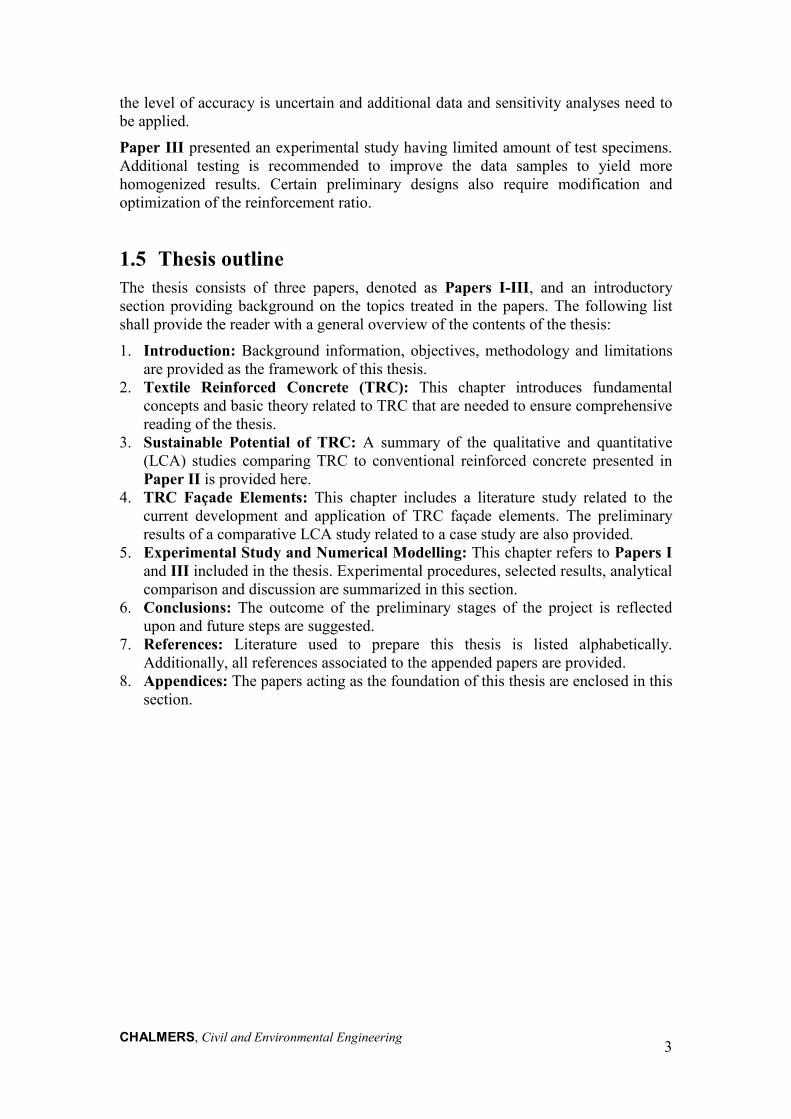
2.1.1. Materials The choice of fibre material for use in TRC is based on various factors such as materials properties, corrosion and temperature resistance, bond quality, demand/production cost and even environmental impact. In terms of mechanical behaviour, tensile strength, breaking elongation and modulus of elasticity superior to those related to the cementitious matrix is essential. The reinforcement ratio and placement of the textile reinforcement will also have a great impact on the composite behaviour of a TRC member (Brameshuber, 2006). Fibre materials which have generally been used and explored in TRC include, but are not limited to: alkali-resistant glass (AR-glass), carbon, basalt, aramid, polyvinyl-alcohol (PVA) with polyvinyl chloride (PVC) coating. In this thesis, it is primarily of interest to explore the use of AR-glass, basalt and carbon fibres as these are currently the most readily available and applied materials, see Figure 2.3.
Figure 2.3 Examples of AR-glass, carbon and basalt fibre meshes. Glass fibres are chemical fibres derived from inorganic non-metallic raw materials (Wulfhorst et al., 2006). The raw materials needed to produce AR-glass are primarily silica sand (SiO2) and the addition of zircon (ZrO2) to provide a superior alkali resistance, which are proportioned through a batching process. These raw materials undergo a melting process between 1250 to 1350°C, wherein molten glass is yielded. Fiberization of the molten glass takes places afterwards, meaning that fibres are produced through a wet-spinning process (Wulfhorst et al., 2006). The glass fibre filaments are then sized to primarily protect them against damage during packaging and finishing. Coating is often applied during sizing to obtain a specified surface wetting and bonding of the filaments (Parnas et al., 2007). Moreover, basalt fibres are mineral fibres extracted from volcanic rock. The manufacturing of basalt is rather similar to that of glass fibres. Basalt fibres do not contain other additives in terms of raw material and, as a result, involve simple and conventional processes and equipment which is said to be cost-effective (Wei et al., 2010).
Carbon Basalt AR-Glass

CHALMERS, Civil and Environmental Engineering
7
Carbon fibres are chemical fibres that can be produced by two methods: 1) based on polyacrylonitrile (PAN) and 2) based on meso phases pitch (petroleum). Production method 1 is explained here, but each method aims for carbon fibres having at least 90 % carbon content. The precursor to make carbon fibre is called polyacrylonitrile, an organic polymer resin produced by a polymerization process. This polymer undergoes wet-spinning to fabricate chemical fibres which are then drawn into filaments. These chemical fibres are thermally stabilized, i.e. removal of non-carbon atoms, through oxidation prior to being exposed to high temperatures. In order to align the graphite layers parallel to the fibres, these fibres go through carbonization and graphitization, i.e. surface treatment, at temperatures between 1000-3000°C. Unsized carbon filament yarns are the resulting end-product of the above mentioned processes, but to be able to improve the bond surface, sizing of the filament yarns is typically included in the production process (Wulfhorst et al., 2006).
Furthermore, a qualitative assessment of general mechanical and chemical properties including corrosion and temperature resistance, bond quality, in addition to demand and production cost for each of selected reinforcements was conducted in Paper II and is summarized in Table 2.1. Each criterion is assessed on a scale from Low to High based on a relative comparison between conventional steel reinforcement, AR-glass, carbon and basalt textile reinforcements for use in concrete. This assessment is primarily based on data retrieved from (Brameshuber, 2006) or otherwise stated. Additional details regarding the assessment can be retrieved from Paper II.
In summary, it is challenging to simply select an optimal reinforcement material from this qualitative assessment partially due to rather comparable properties highlighted for each alternative. Conventional steel reinforcement appears to be a relatively good solution, but history of the breakdown of its corrosion resistance and related deterioration in itself is an aspect motivating the use of alternative solutions. When comparing the novel materials, namely AR-glass, carbon and basalt, AR-glass appears to be the most effective option. Carbon presents many advantages but its high initial cost and relatively low availability in regards to textile reinforcement are drawbacks. Basalt is comparable to AR-glass, but is still in need of much research in terms of use as reinforcement in cementitious matrices.

CHALMERS, Civil and Environmental Engineering
8
Table 2.1 Qualitative assessment of selected reinforcements.
Reinforcement Material
Corrosion Resistance
Temperature Resistance
Bond Quality Demand / Production Cost
Conventional Steel Reinforcement
> High resistance to high alkaline solutions (passive film)
> Low resistance to low alkaline, neutral or realistic acidic outdoor conditions
> Average resistance
> High thermal expansion and conductivity (Saertex, 2013)
> Low to High, depending on mechanical deformations
> High/Average > Commonly used
AR-Glass > Average to High resistance to alkali attack
> High resistance to neutral or realistic acidic outdoor conditions
> Low resistance
> Average thermal expansion (Saint-Gobain
Vetrotex, 2011,
Saertex, 2013) > Low thermal
conductivity (Saint-Gobain
Vetrotex, 2011,
Saertex, 2013)
> Average > Depends on
density of yarn > Improve with
coatings
> Average/ Average
> Particularly produced for use in alkaline environments
Carbon > High resistance to acid, alkaline and organic solvents (inert)
> High resistance
> Low thermal expansion
> Shortens when heated
> Average thermal conductivity (Saertex, 2013)
> Low to Average
> Smaller filament diameter leads to weaker adhesion of yarn
> Improve with coatings
> Low/High > Compared to
AR-glass
Basalt > Comparable to unsized E-glass and AR-glass in high alkaline solutions (Scheffler et al.,
2009a, Förster et al.,
2010)* > High
resistance to neutral or realistic acidic (Wei et al., 2010) and alkaline outdoor conditions (Van
de Velde et al., 2003)
> High resistance
> Low thermal expansion
> Geometrically stable (Smarter
Building Systems,
2010) > Low thermal
conductivity (Smarter Building
Systems, 2010)
> Average > Unsized
filaments (Scheffler et al.,
2009a) > Low friction
coefficient > Improve with
coatings (Scheffler et al.,
2009a)
> Low/Average > Easily
extractable natural resource
(Förster et al., 2010,
Smarter Building
Systems, 2010)
*Uncertainties exist due to unknown chemical formulation of basalt and fibre sizings, which as result caused observations of high standard deviation values in tensile strength after ageing (Scheffler et al., 2009a, Förster et al., 2010)
CHALMERS, Civil and Environmental Engineering
9
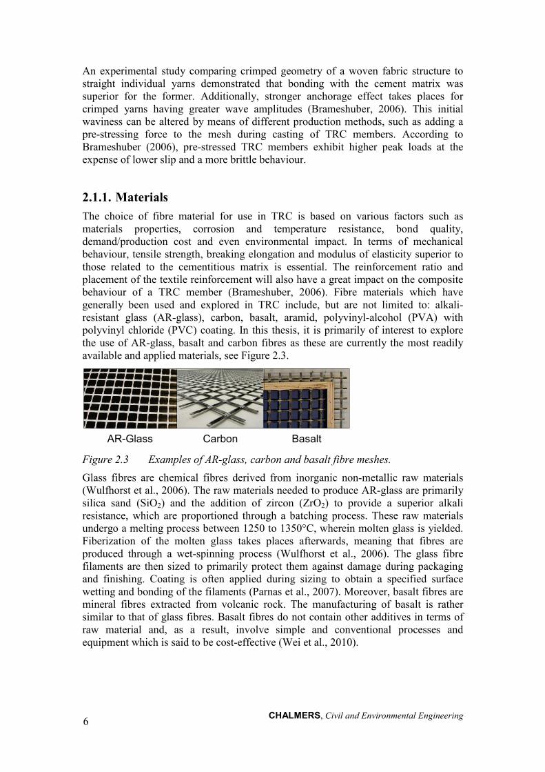
2.2. Cementitious matrix The cementitious matrix in TRC differs from that typically used in conventional steel reinforced concrete. Fine-grained concrete also defined as mortar is prescribed for TRC, where the maximum aggregate size is < 2 mm. Highly flowable concrete is needed to adequately penetrate the textile reinforcement mesh structure in order to provide sufficient bond and load transfer. An example of a mix composition (w/c = 0.42, w/ceq = 0.33) used in experimental work covered in this thesis is provided in Table 2.2 (refer to Paper I).
Table 2.2 Mix composition of fine-grained concrete matrix.
Material Weight (kg/m3)
Density (kg/m3)
m3/m3
Low-alkali cement
406 3200 0.127
Fly ash 121 2300 0.053 Mircrosilica 22 2200 0.010
0/4 sand 1400 2640 0.530 Glenium SKY
532-SU 7.6 1100 0.007
Amex SB 22 3 1010 0.003 Water 170.56 1000 0.171
Air 0.100 Total 2130.16 1.000
In addition, the cementitious matrix should be chemically compatible with the selected textile reinforcement, while providing the desired load-carrying capacity, mechanical behaviour and suitable characteristics for the specimen geometry and production method (Brameshuber, 2006). Despite the awareness of these design details, the improvement of the corrosion protection of novel textile reinforcements in TRC, particularly AR-glass, has been the subject of research (Büttner et al., 2011). For example, nano-composite polymer coatings have been developed primarily for AR-glass to form a barrier against alkali ions, as well as to increase durability and mechanical behaviour of TRC (Scheffler et al., 2009c). Which other methods could be developed to improve the durability of the composite? It is presumed that the cementitious matrix could potentially be designed such that the concentration of alkali ions is reduced in the surrounding of the textile reinforcement mesh. A polymer-modified concrete and its influences on the durability of TRC has been developed by (Büttner et al., 2009) for instance. However, inadequate studies exist on this topic; as such, research dealing with modifications of the chemical and mechanical composition of the cementitious matrix design in TRC could be meaningful for improved durability.
2.3. Mechanical behaviour To explain the tensile behaviour of textile reinforcement alone, we turn to a fundamental example showing the stress-strain relationships for steel reinforcement versus carbon textile mesh reinforcement derived from Schladitz et al. (2012) and illustrated in Figure 2.4. This comparison is important to highlight as the design of TRC members will inevitably need to account for these behavioural differences.

CHALMERS, Civil and Environmental Engineering
10
Figure 2.4 Idealized stress-strain law for steel versus carbon textile reinforcement
under tensile loading (Redrawn from Schladitz et al. (2012)). Steel reinforcement typically yields at yield stress, fs,y at a corresponding strain of, εs,y ≈ 3.0 ‰, thereafter its stiffness critically decreases and undergoes a ductile failure when reaching its ultimate stress, fs,u . However, concerning carbon textile reinforcement, it initially has low stiffness indicated by the first branch of the curve from 0 to εt,1, in Figure 2.4, which can be explained by the initial crimping/undulation existing within the mesh structure of the reinforcement. As the yarns are straightened out due to an increase in tensile force taken up by the yarns, an increase in stiffness occurs in the second branch of the curve from εt,1 to εt,lim. The carbon textile reinforcement undergoes a brittle failure at the ultimate limit strain, εt,lim ≈ 11-12.0 ‰ (Schladitz et al., 2012).
Furthermore, it does not suffice to simply describe the reinforcement behaviour, thus, we turn to a case of a one-way slab reinforced by one layer of carbon textile reinforcement under four-point bending to discuss the composite behaviour. The load versus mid-span deflection is depicted in Figure 2.5 along with indicated loading states. There are technically three applicable states for TRC, but four are mentioned in Brameshuber (2006) to draw a parallel between conventionally reinforced concrete and TRC: State I (uncracked concrete), State IIA (crack formation), State IIB (crack stabilization), and State III (ductile deformation).
CHALMERS, Civil and Environmental Engineering
11
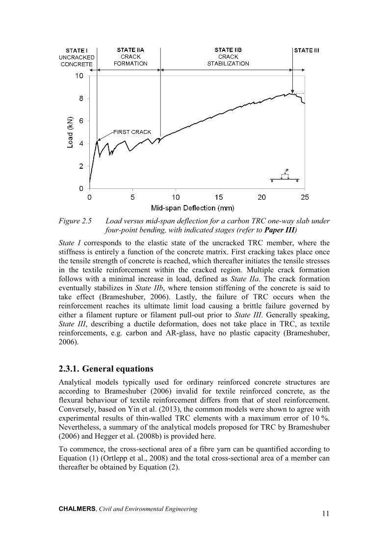
Figure 2.5 Load versus mid-span deflection for a carbon TRC one-way slab under
four-point bending, with indicated stages (refer to Paper III) State I corresponds to the elastic state of the uncracked TRC member, where the stiffness is entirely a function of the concrete matrix. First cracking takes place once the tensile strength of concrete is reached, which thereafter initiates the tensile stresses in the textile reinforcement within the cracked region. Multiple crack formation follows with a minimal increase in load, defined as State IIa. The crack formation eventually stabilizes in State IIb, where tension stiffening of the concrete is said to take effect (Brameshuber, 2006). Lastly, the failure of TRC occurs when the reinforcement reaches its ultimate limit load causing a brittle failure governed by either a filament rupture or filament pull-out prior to State III. Generally speaking, State III, describing a ductile deformation, does not take place in TRC, as textile reinforcements, e.g. carbon and AR-glass, have no plastic capacity (Brameshuber, 2006).
2.3.1. General equations Analytical models typically used for ordinary reinforced concrete structures are according to Brameshuber (2006) invalid for textile reinforced concrete, as the flexural behaviour of textile reinforcement differs from that of steel reinforcement. Conversely, based on Yin et al. (2013), the common models were shown to agree with experimental results of thin-walled TRC elements with a maximum error of 10 %. Nevertheless, a summary of the analytical models proposed for TRC by Brameshuber (2006) and Hegger et al. (2008b) is provided here.
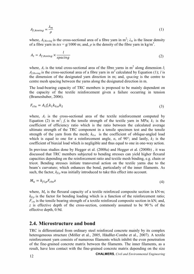
To commence, the cross-sectional area of a fibre yarn can be quantified according to Equation (1) (Ortlepp et al., 2008) and the total cross-sectional area of a member can thereafter be obtained by Equation (2).
CHALMERS, Civil and Environmental Engineering
12
𝐴𝑓,𝑅𝑜𝑣𝑖𝑛𝑔 =𝜆𝑚𝜌
(1)
where, Af,Roving is the cross-sectional area of a fibre yarn in m2; λm is the linear density of a fibre yarn in tex = g/1000 m; and, ρ is the density of the fibre yarn in kg/m3.
𝐴𝑡 = 𝐴𝑓,𝑅𝑜𝑣𝑖𝑛𝑔 ×𝑙
𝑠𝑝𝑎𝑐𝑖𝑛𝑔 (2)
where, At is the total cross-sectional area of the fibre yarns in m2 along dimension l; Af,Roving is the cross-sectional area of a fibre yarn in m2 calculated by Equation (1); l is the dimension of the designated yarn direction in m; and, spacing is the centre to centre mesh spacing between the yarns along the designated direction in m.
The load-bearing capacity of TRC members is proposed to be mainly dependent on the capacity of the textile reinforcement given a failure occurring in tension (Brameshuber, 2006).
𝐹𝑐𝑡𝑢 = 𝐴𝑡𝑓𝑡𝑘1𝑘0,𝛼𝑘2 (3)
where, At is the cross-sectional area of the textile reinforcement computed by Equation (2) in m2; ft is the tensile strength of the textile yarn in MPa; k1 is the coefficient of efficiency ratio which is the ratio between the calculated average ultimate strength of the TRC component in a tensile specimen test and the tensile strength of the yarn from the mesh; k0,α is the coefficient of oblique-angled load which is equal to one for a reinforcement angle, α, of 90°; and lastly, k2 is the coefficient of biaxial load which is negligible and thus equal to one in one-way action.
In previous studies done by Hegger et al. (2008a) and Hegger et al. (2008b) , it was discussed that TRC members subjected to bending stresses can yield higher flexural capacities depending on the reinforcement ratio and textile mesh binding, e.g. chain or tricot. Bending stresses initiate transversal action on the textile yarns due to the beam’s curvature; which enhances the bond, particularly of the inner filaments. As such, the factor, kfl,p was initially introduced to take this effect into account.
𝑀𝑢 = 𝑘𝑓𝑙,𝑝𝐹𝑐𝑡𝑢𝑧 (4)
where, Mu is the flexural capacity of a textile reinforced composite section in kN∙m; kfl,p is the factor for bending loading which is a function of the reinforcement ratio; Fctu is the tensile bearing strength of a textile reinforced composite section in kN; and, z is effective depth of the cross-section, commonly assumed to be 90 % of the effective depth, 0.9d.
2.4. Microstructure and bond TRC is differentiated from ordinary steel reinforced concrete mainly by its complex heterogeneous structure (Möller et al., 2005, Häußler-Combe et al., 2007). A textile reinforcement yarn consists of numerous filaments which inhibit the even penetration of the fine-grained concrete matrix between the filaments. The inner filaments, as a result, have less contact with the fine-grained concrete matrix depending on the size

CHALMERS, Civil and Environmental Engineering
13
of the fill-in zone. The fill-in zone is the depth at which adhesive load transfer can take place between the filaments and the matrix. As well, the inner zone, so-called core, is defined as filaments having less contact with the matrix but assuming that frictional load transfer between the filaments is possible (Hartig et al., 2008). The yarn structure embedded in a matrix along with these abovementioned associated zones is conceptualized by Figure 2.6.
Figure 2.6 Conceptualized yarn structure (Based on (Hartig et al., 2008)). As described in Paper II, small cross-sections of a carbon textile mesh (3500 tex; 18 (90°) x 11 (0°)) were impregnated with fluorescent epoxy in order to enable microscopy-images of the yarn structure and to exemplify the variability in transitions existing between filaments and matrix. The cross section of a warp yarn, denoted as Section A-A, was magnified to 1 mm and was further magnified to 50 μm, as illustrated in Figure 2.7. It is of interest to highlight the following:
• Filaments are easily detected in black; • Fluorescent yellow indicates epoxy penetrated between the filaments; • Zones not in contact with epoxy are white and indicated by arrows (refer to
50 μm); • Core filaments neighbouring white zones are weakly linked and cannot
transfer load (Hartig et al., 2009); • Localized bunching of external filaments are circled (refer to 1 mm).
Figure 2.7 Magnification of epoxy impregnated thin cross-sections of carbon
textile mesh (Williams Portal et al., 2013).

CHALMERS, Civil and Environmental Engineering
14
The complex heterogeneity of TRC along a cross-section, undoubtedly described through Figure 2.7, is highly variable and can be affected by many factors such as, textile material properties, yarn cross-section and geometry, yarn fineness, binding type, cementitious matrix properties, embedment length and reinforcement ratio. The impregnation of the textile mesh using e.g. polymer-based coatings is often used to eliminate the highly heterogeneous structure of the yarn whereby attempting to create a uniform bond surface between the cement matrix and the mesh (Hartig et al., 2008, Hegger et al., 2008b, Hartig et al., 2009). It is thought that the load-carrying behaviour could be enhanced through such material adjustments. A deeper discussion of how the tensile strength of a TRC member could potentially be altered by utilizing different textiles, binding types, and surface coatings is based on Hegger et al. (2008b) and provided in Paper II.
2.5. Durability TRC is presumed to eliminate the issue of corrosion within reinforced concrete, but what other deterioration mechanisms could potentially arise over time using this composite material? The knowledge about the long-term durability of novel textile reinforcements is limited. Though, the durability of TRC is assumed to be indirectly comparable to that of FRC, which has been evaluated substantially. The mechanical behaviour of FRC is complex as it varies over time and is dependent on the fibre-matrix combination (Brameshuber, 2006). A similar complexity is thought to exist for TRC, and as such the durability of different types of novel textile reinforcements need to be studied and quantified. To date, there exists no long-term performance information about TRC in the field (Mechtcherine, 2012) but several accelerated material tests and durability models have been explored (Brameshuber, 2006). Mechtcherine (2012) states, however, that a realistic and reliable performance-based durability design concept still needs to be developed in order to further optimize the usability of TRC.
2.5.1. AR-glass Durability research regarding TRC has primarily focused on AR-glass, as this material has been shown to be the most cost effective and available novel textile reinforcement solution, as aforementioned in Section 2.1.1. Even though the name itself suggests that it is resistant to an alkali environment, Purnell (1998) indicated that it undergoes strength loss in cementitious matrices over time. The main reason for strength loss is due to the presence of small defects and or weak zones in the AR-glass fibre surface, which make the fibres susceptible to stress concentrations, pitting corrosion and local displacements in an alkaline environment (Purnell, 1998, Orlowsky et al., 2005). Continued hydration of the cementitious matrix causing matrix densification at the fibre-matrix interface could also potentially degrade the composite (Brameshuber, 2006). Time-dependent strength loss of AR-glass fibres used in a fine-grained concrete matrix was investigated using corrosion models (Purnell, 1998, Orlowsky et al., 2005) and further expanded including weathering conditions. By including weathering conditions, such as humidity and temperature, a more realistic prediction of strength loss was obtained over time (Cuypers et al., 2007). Ways of improving the durability of AR-glass include the reduction of the pH-level in the concrete matrix particularly near the fibres, as well as the inclusion of a

CHALMERS, Civil and Environmental Engineering
15
hydrophobic protection layer, e.g. epoxy, around the fibres to act as a diffusion barrier against the alkaline solution (Büttner et al., 2011, Raupach et al., 2011). In accelerated ageing tests, it was found that fibre impregnation has the greatest impact on the improvement of strength durability. Furthermore, in more recent attempts of time-dependent modelling, it was found that AR-glass could have a 30 % strength loss for a design service life of 50 years when concrete carbonation and fibre impregnation are neglected (Hegger et al., 2010).
2.5.2. Carbon Carbon fibres are thought to be resistant to alkaline-induced deterioration due to their chemical inertness (Scheffler et al., 2009b), but this hypothesis is not based on long-term weathering analysis (Brameshuber, 2006). Research on carbon FRC shows that strength and toughness of high modulus (HM) polyacrylonitrile (PAN) carbon-FRC reaches its optimum strength at around 30 days when embedded in a cementitious matrix, and thereafter, a decline in these properties are observed likely due to matrix densification. This behaviour is not necessarily observed for lower modulus carbon fibres (Brameshuber, 2006).
Furthermore, despite the fact that literature on carbon fibres used in TRC is limited, the knowledge gained from developing sizing and coatings for AR-glass fibres have also been investigated for carbon fibres by (Scheffler et al., 2009b, Scheffler et al., 2009c). Assuming that carbon fibres do not suffer from the same surface flaws as AR-glass, the bond at the fibre-cementitious matrix interface becomes the limiting factor in terms of the performance of carbon fibres (Scheffler et al., 2009b). The application of selected nano-dispersed polymeric coatings to carbon fibres was observed to improve the bond between the fibres and cementitious matrix, resulting in enhanced tensile strength and fracture energy (Scheffler et al., 2009c). Based on the current research knowledge, carbon fibres used in TRC appear to have favourable durability prospects.
2.5.3. Basalt Basalt fibres are mineral fibres extracted from volcanic rock. Due to its natural formation process, its raw material content and morphology can differ greatly depending on its source. This variability in raw materials poses a challenge, as it can have a large influence on the chemical and mechanical properties and durability of the fibres. In most recent studies, basalt fibres are compared to glass fibres, such as E-glass and AR-glass, due to existing similarities in their chemical composition (Van de Velde et al., 2003, Scheffler et al., 2009a, Wei et al., 2010). Since the evaluation of long-term chemical resistance of mineral fibres is said to be ambiguous, accelerated ageing experiments with defined boundary conditions is the chosen method used to observe their durability (Wei et al., 2010). Basalt and glass fibers have been immersed in both sodium hydroxide (NaOH) and hydrochloric acid (HCl) solutions for varying time periods by (Wei et al., 2010), and it was concluded that basalt has superior acid resistance compared to E-glass, but are similar in terms of alkali resistance. A previous study by Van de Velde et al. (2003) has shown, however, that basalt fibres and yarns have higher alkali resistance in comparison to E-glass when submerged in simulated concrete conditions of saturated Ca(OH)2. A comparison between basalt and AR-glass by (Förster et al., 2010) demonstrated that one of the tested basalt

CHALMERS, Civil and Environmental Engineering
16
specimens had a similar drop in tensile strength, but with high standard deviation, after ageing seven days in a cement solution. According to studies executed by (Förster et al., 2010, Förster et al., 2011), basalt fibres were also shown to age differently in NaOH solutions compared to a cement solution or 3-ionic solutions; such that the formation of a peeling shell occurs in NaOH solutions and local attacks in the other solutions. Commercially available basalt fibres, which are usually unsized and which have been used as concrete reinforcement, have been observed to be only suitable in low-alkali concrete matrices. Despite the fact that their alkali resistance is stated to be superior than E-glass, the use of an alkali-resistant coating or fibre modification are proposed to enhance tensile strength and durability (Förster et al., 2011).

CHALMERS, Civil and Environmental Engineering
17
3 Sustainable Potential of TRC [Paper II] 3.1 Motivation The deterioration of concrete structures exposed to humid and saline environments is typically caused by corrosion of steel reinforcement (Malaga et al., 2012). The protective design cover mandated by EC2 for steel reinforced concrete structures ranges from 30-75 mm (EN 1992, 2004), which can significantly be reduced when using non-corrosive textile reinforcements (Brameshuber, 2006). For instance, it was found by Tomoscheit et al. (2011) that approximately 85 % less concrete is needed for TRC applications using carbon or AR-glass textiles. Furthermore, by conserving energy-demanding materials, such as concrete of Portland cement, the environmental impact of concrete structures can be reduced (Mehta, 2001, Brameshuber, 2006). Additionally, in the case of lightweight and thin TRC facades, the need for complex anchorage systems is eliminated (Brameshuber, 2006), the environmental impact resulting from transportation from gate-to-use is reduced (Tomoscheit et al., 2011, Malaga et al., 2012), as well, the liveable area within a building can be increased. Within the EU-funded LIFE project entitled INSUSHELL, the application of a self-supporting façade element made of thermally insulated TRC was discovered to save not only high energy and CO2 in the production phase, but also during the construction phase (Insu-Shell-Projekt LIFE, 2009).
3.2 Cyclical perspective Based on the current trends and regulations towards zero energy and/or zero carbon buildings, the importance of the environmental performance of construction materials becomes even more indispensable in the near future. EU’s 20-20-20 goal and the Energy Performance of Buildings Directive (EPDB) are current examples of adopted goals and legislations mandating that all new buildings need to be zero energy buildings by 2020 within the European Union. Buildings are a necessity for society but are also one of the greatest energy consumers, thus underlining the need for energy-optimized technologies and constructions. Traditional solutions need an added sustainable element since they primarily focus on cost, performance and quality objectives. Enhancing the ecological sustainability of building materials is beneficial not only in terms of cost and energy savings (Kibert, 2012), but also help reduce maintenance and frequency of raw material extraction, as well as increasing the service life of a building.
Vast amounts of building materials exist and are continuing to be developed, but the methods by which their level of sustainability is evaluated remain vague and there is a need for greater transparency. In other words, the categorization of building materials leading to energy-optimized technologies and constructions is not described in the goals and legislations. A method that could be used to expose the environmental impacts of building materials is Life Cycle Assessment (LCA). Environmental standards or recognized certification systems, such as Building Research Establishment Environmental Assessment Method (BREEAM) or Leadership in Energy and Environmental Design (LEED), attempt to address the life-cycle impact of construction materials. BREEAM’s Green Guide to Specification analyses building materials according to their life-cycle impacts; whereas LEED simply emphasize the use of recyclable materials and material reuse. The harmonization of standards for

CHALMERS, Civil and Environmental Engineering
18
construction materials has been recently directed by requirement no. 7 of EU’s Construction Products Regulation which further commends the need for analysis of the sustainable potential of building materials. These discussed facts justify the need for a comprehensive analysis of the sustainable potential of TRC in comparison to conventional building materials, which is covered in Paper II.
3.3 Life Cycle Assessment (LCA) To capture the sustainable potential of TRC, a Life Cycle Assessment (LCA) was performed wherein conventional steel reinforced concrete and TRC were compared. This assessment has been done according to a cradle-to-gate perspective, so to say extraction and production processes, in order to observe the environmental effects of reducing the concrete cover in TRC structures, as well as those involved in the production of different reinforcement materials. This study is related to a functional unit of 1 m2 of reinforced concrete. To adequately compare the reinforced concrete alternatives, the one-way flexural capacity of a conventionally steel reinforced concrete section of 1 x 1 x 0.08 m is selected as a reference. The one-way flexural capacity was calculated assuming that the inner lever arm is 90 % of the effective cross-sectional depth. The TRC alternatives are normalized with regards to thickness and quantity of textile reinforcement layers to meet the flexural capacity of the reference section. Details regarding the selected cradle-to-gate data, material inputs, assumptions and impact assessment methods used in this LCA are described in Paper II.
3.3.1 Results The total energy consumption of the reinforcement materials for a cradle-to-gate perspective can give a preliminary overview of a demand trend existing between the reinforcing materials, as per Figure 3.1.
Figure 3.1 Cumulative energy consumption of reinforcement materials, functional
unit of 1 kg versus 1 m2. By comparing the two functional units, shown in Figure 3.1, it is observed that after the adjustment of the reinforcement quantity from 1 kg to the functional unit 1 m2, a similar trend remains between the total energy consumption of each reinforcement
0
20
40
60
80
100
120
140
Steel Glass Carbon Basalt
Cum
ulat
ive
Ene
rgy
Dem
and
[MJ]
Reinforcement (1 kg)
Reinforcement ((1 m2)

CHALMERS, Civil and Environmental Engineering
19
material. It is clear that carbon fibre has a significantly greater demand, despite its decrease after the adjustment, compared to all other materials. Glass fibre has a greater demand than steel and basalt, whilst basalt has the lowest demand. When grouping the total energy consumption of the reinforcement and the corresponding concrete amount, the trend shifts dramatically as indicated in Figure 3.2.
Figure 3.2 Total energy consumption of reinforced concrete alternatives,
functional unit of 1 m2. Basalt reinforcement has the least total energy consumption, even when three layers of reinforcement mesh necessary to reach the reference bending capacity are included. Both glass and carbon reinforcements have a greater impact than steel in Figure 3.1, but when grouped with concrete, their overall impact becomes lower than steel. From these results, it is apparent that concrete is the dominating variable in this equation, such that its demand makes up 75-90 % of the total energy demand for a reinforced concrete element. A decrease in concrete can thus have a substantial impact on the total energy consumption of a reinforced concrete element. The allowable decrease of concrete in TRC compensates for an increase in textile reinforcement and associated increase in energy consumption, particularly in the case of glass and carbon fibres. Furthermore, LCA results related to the environmental impact of the reinforced concrete alternatives are elaborated in Paper II.
3.3.2 Limitations LCA based on a cradle-to-gate perspective showed that the possible reduction of concrete in TRC is observed to considerably decrease the cumulative energy demand and environmental impact of a reinforced concrete element. Additionally, basalt fibre reinforced concrete was observed to yield the least cumulative energy demand while carbon fibre reinforced concrete yielded the least environmental impact. The environmental sustainable potential of TRC in comparison to conventional steel-reinforced concrete has been successfully highlighted in Paper II. Such analyses can help conceptualize ecologically sustainable building solutions for implementation in the construction industry in Sweden and abroad.
The presented LCA analysis was limited to one particular reference configuration which could certainly be further optimized. A given application could be considered, such as the design of a sandwich panel, or the reinforcement-concrete ratio could be varied and assessed.
0
50
100
150
200
250
300
350
400
450
Steel Glass Carbon Basalt
Cum
ulat
ive
Ener
gy D
eman
d [M
J/m
2 ]
ConcreteReinforcement

CHALMERS, Civil and Environmental Engineering
20
It would be valuable to perform an LCA analysis covering an entire life-cycle of a textile reinforced concrete element as it would identify potential paybacks over a long-term period. However, it remains a challenge to quantify the long-term behaviour of TRC and further research is still needed (Mechtcherine, 2012).
It is important to highlight that life-cycle inventory data might be different from country to country and as a next step, a sensitivity study should be conducted to assess the possible impact that these data may have on the overall results. Another step that could be explored in future analyses is the use of a more homogenous source of data. For example, different data sources imply inconsistencies regarding the system boundaries and accuracy of gathering data. Accordingly, a more homogenous source of data could slightly change or affect the LCA results.

CHALMERS, Civil and Environmental Engineering
21
4 TRC Façade Elements – A Sustainable Application TRC façade elements have recently been developed and applied in a multitude of projects over the past decade. TRC is said to be a sustainable application as it includes non-corrosive reinforcement which grants the fabrication of thin, light-weight and modular façade elements. A brief introduction to possible façade element solutions is discussed in the following, as well as recent work related to TRC façade elements. The development and optimization of sustainable and interchangeable façade elements made of TRC were evaluated.
4.1 Applications The thickness of commonly used precast concrete elements with steel reinforcement is determined based on the application, minimum concrete cover and fire resistance requirements. The use of metallic connectors are also typically incorporated in the design of these elements (Losch et al., 2011). The inclusion of non-corrosive reinforcement, in the form of multi-directional textile fabrics, can permit a reduction of panel thickness which, in turn, yields light-weight and slender concrete façade elements. Accordingly, TRC has been recently applied in new construction in the form of lightweight and thin self-supporting sandwich elements as well as large-sized ventilated façade elements (Brameshuber, 2006, Insu-Shell-Projekt LIFE, 2009, Hegger et al., 2011b). A general overview of two possible wall assembly configurations using TRC is depicted in Figure 4.1.
Figure 4.1 Sandwich elements and cladding panels out of TRC: a) Sandwich
elements with facing shell of textile concrete, b) Ventilated façade system: textile-reinforced cladding panel with air gap (Redrawn based on (Brameshuber, 2006)).
Sandwich elements typically consist of an external facing panel, a non-structural thermal insulation followed by a structural load-bearing layer at the interior (Hegger et al., 2008c). These elements can also be categorized as non-composite, wherein the facings are independent of each other. Elements can also be designed as partially composite or composite. Partially composite elements transfer shear stresses partly by means of ties connecting the facings. As for composite elements, the facings are designed to resist loads as a unit, i.e. full-composite action; accordingly, full shear transfer occurs between the facings (Losch et al., 2011). The load bearing behaviour
CHALMERS, Civil and Environmental Engineering
22
of these elements, assuming rigid facings, is dependent on the overall height, layer thicknesses and insulating core stiffness (from Stamm et al. (1974) in (Hegger et al., 2008c)). A higher core stiffness, so-called shear modulus, increases the composite action, such that shear stresses can be transferred to the facings (Hegger et al., 2008c), which in turn decreases shear deformations (Losch et al., 2011).
A ventilated façade system consists of a thin external facing panel that is separated from the primary wall structure by a naturally ventilated cavity (air gap). This cavity allows for drainage of moisture ingress from rain and condensation, which helps minimize the deterioration of the adjacent inner layers of the wall assembly. The external panels typically have a thickness of 20-35 mm and can span large areas over 12 m2. The shortcomings of this application is that bracing substructures are required for panels spanning large areas to limit the deformation/warping of the thin facing panel (Tomoscheit et al., 2011).
Life INSU-SHELL, a collaborative project between RWTH Aachen University and industrial partners, involved the development and implementation of innovative and eco-friendly sandwich façade elements (3425 x 975 x 180 mm) made of thermal insulation (rigid polyurethane foam, 150 mm) and two textile reinforced glass fibre reinforced concrete (GFRC) facings (15 - 40 mm) (Tomoscheit et al., 2011). Compared to the TRC sandwich element (a) shown in Figure 4.1, the structural concrete layer was replaced by a thin TRC layer which noticeably reduced the overall thickness and also the number of required connectors by 40 % (Hegger et al., 2011b). This application was able to reduce a large quantity of concrete material leading to 70 % less CO2 output than ferro-concrete elements, as previously mentioned in Section 3. The mechanical properties of the designed TRC sandwich panel, namely load-bearing behaviour and capacity, were evaluated using static and dynamic four-point bending tests. The failure mode observed for all tested sandwich panel specimens was shear rupture of the core due to the high load-bearing capacity of the TRC facings. The adhesive bond between the insulating core and TRC facings was found to be a critical factor influencing the magnitude of the shear force at rupture. The chosen pin connectors adequately allowed for secondary shear transfer from to the facings to the core. All tested panels exceeded the ULS design values. The TRC facings were observed to minimize the visual crack development in both SLS and ULS (Tomoscheit et al., 2011).
In Horstmann et al. (2011), two types of sandwich panels were investigated: 1) with two TRC-facings, 2) one outer TRC facing with a thicker inner concrete layer. AR-glass with epoxy coating and carbon textile reinforcements were used in the TRC facings. Foam insulation, e.g. expanded polystyrene (EPS), extruded polystyrene (XPS) and polyurethane foam (PU), were evaluated for the sandwich panels and mechanical behaviour were quantified through a series of material tests. To further improve the shear transfer from the facings to the insulation core, connecting devices made of fibre reinforced polymer (FRP) connectors and carbon fibre shear grids were considered. The FRP connectors resulted in improved ductile load-deformation behaviour due to secondary effects such as friction; however, an increase in initial stiffness was not observed and the composite strength was found to decrease in tensile tests. Conversely, the shear grids increased both the stiffness and load capacity compared to the tests without connectors. An increase of shear grid cross-section resulted in increased load capacity, stiffness and ductility. Concerning the flexural capacity of the sandwich elements, large variations were observed depending on the selected connector/shear grid configuration. The load-carrying capacity was mainly

CHALMERS, Civil and Environmental Engineering
23
determined by the shear strength of the insulation, while the shear grid mainly influenced the ductility which increased the deformation capacity of the insulation after cracking in shear.
Self-supporting sandwich panels made of GFRC and standard fine-grained concrete reinforced by uncoated or epoxy impregnated AR-glass fabrics were evaluated in Hegger et al. (2009). Insulation material variants, such as PU rigid foams and XPS, and alternative production methods, i.e. gluing or notched core, were investigated. A series of sandwich panels underwent both bending and shear tests which determined that adequate load-bearing behaviour was achieved. The deterministic factors included the shear stiffness of the insulating core as well as the bond between the TRC facings and the core. Overall, failure was governed by shear failure in the insulating core. Moreover, the development of modular roof and wall sandwich elements using GFRC and tailored 3D AR-glass textile reinforcement was also explored in Hegger et al. (2009). The combination of these two reinforcing materials was found to provide prospective applications in regards to light-weight structures with complex geometry. As well, the precast modular elements help meet the demands of sustainable and versatile construction.
Moreover, lightweight TRC sandwich elements (2000 x 2500 mm) with external TRC facing (40 mm), mineral wool insulation (150 mm), and inner load bearing layer (150 mm) were produced and tested by Malaga et al. (2012). The study consisted of TRC facings reinforced in two ways: 1) epoxy-coated glass rods (φ 6 mm) arranged in bi-directional pattern, 2) carbon fibre reinforcement mesh. The sandwich elements were tested in a wind chamber and the measured displacements were found to be relatively small and the placement of the reinforcement in the facing was a sensitive parameter. Overall, these options were concluded to withhold potential for future applications.
Textile-reinforced cladding panels, that is to say curtain wall panels were developed for the extension of the Institute of Structural Concrete, RWTH Aachen University, shown in Figure 4.2. These panels were designed at the Collaborative Research Centre 532, Aachen and produced by Hering. Coated AR-glass fibre mesh was used as reinforcement which was applied in two layers near the surface (≈ 3 mm cover) (Brameshuber, 2006). This type of panel is designed for wind load and ensures no cracking under service loads.
Figure 4.2 Curtain wall construction of the Structural Concrete Institute, RWTH
Aachen University.

CHALMERS, Civil and Environmental Engineering
24
TRC cladding panels are also produced in larger scales mainly by Hering GmbH, Germany and Fydro BV, NL. Hering GmbH produces a TRC façade element reinforced with AR-glass fibre mesh entitled betoShell® which can have a thickness within the range of 20 - 40 mm; the design of this element originated in the aforementioned collaborative project with Collaborative Research Center 532. Likewise, Fydro produces rear-ventilated cladding panels of TRC reinforced by AR-glass fibre mesh, marketed as Dinamic CCC. These thin and lightweight panels are produced having a thickness of 10 - 25 mm and are supported by aluminium anchors, rivets or structural adhesive. Further benefits include: frost resistance, expected life of 50 years, fire protection and driving rain protection, and so on (Fydro, 2012).
More recently, a pilot study involving a series of experiments on TRC façade panels reinforced by various AR-glass and carbon textile mesh options having varying binding and yarn linear densities (Kulas et al., 2011). Diverse ventilated TRC panel designs considered for several projects, e.g. Community College in Leiden, were developed and underwent bending and tensile tests. Façade panels reinforced by carbon underwent four-point bending tests which verified that they had adequate capacity according to the code requirements. Additionally, theses panels required pin connectors in order to adequately transfer wind loads to the substructure, as such pull-out tests were executed to evaluate the allowable bearing capacity of the pin connectors. Furthermore, the load-bearing behaviour in both longitudinal and lateral directions of large façade panels with edge beams reinforced by AR-glass was also explored. The main requirements for a façade panel include that the load-bearing behaviour is met for the given loading and no cracking is allowed (SLS state). There are no existing standard for the design of TRC façade panels, as such experimental work is required to confirm the load-bearing capacity and behaviour for each individual project.
4.2 Case study: HSB Living Lab Building envelopes fabricated of new technological advances making use of non-traditional types or amounts of material and energy, such as novel insulating and concrete-based materials, might have the potential to be sustainable building solutions. Through the HSB Living Lab as a case study, an interdisciplinary design approach is used to optimize such sustainable building solutions. This case study involves a unique student-accommodation environment comprising of living experience and experimental laboratory having the purpose of promoting innovations, techniques and user practices. The construction of the HSB Living Lab focuses on concepts of sustainability, interchangeability and mobility. The development and optimization of sustainable and interchangeable façade elements made of TRC are the focus of this section.
The primary role of the building envelope is to provide a structural boundary between the exterior and interior environments while maintaining a desired comfort level for the users. It is therefore important that this boundary has good performance and durability in order to sustain its physical function. The concept of sustainability encompasses the choice of durable building materials which could potentially reduce extraction and production of new materials, rehabilitation, replacement, deconstruction, as well as all the resulting energy, emission and waste production. Durable building materials are also beneficial in terms of sustaining an energy-efficient and cost-effective operation of buildings during their life-cycles. Moreover,
CHALMERS, Civil and Environmental Engineering
25
using simplified construction methods such as prefabricated panel elements or volume elements add to the mobility and interchangeability of the structure. The interchangeability of façade elements is an important concept in order to permit the trial of various novel building materials in a real-time environment, as well as to allow for the deconstruction and relocation of the HSB Living Lab.
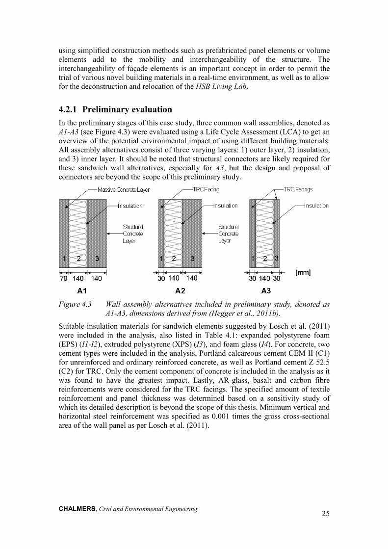
4.2.1 Preliminary evaluation In the preliminary stages of this case study, three common wall assemblies, denoted as A1-A3 (see Figure 4.3) were evaluated using a Life Cycle Assessment (LCA) to get an overview of the potential environmental impact of using different building materials. All assembly alternatives consist of three varying layers: 1) outer layer, 2) insulation, and 3) inner layer. It should be noted that structural connectors are likely required for these sandwich wall alternatives, especially for A3, but the design and proposal of connectors are beyond the scope of this preliminary study.
Figure 4.3 Wall assembly alternatives included in preliminary study, denoted as
A1-A3, dimensions derived from (Hegger et al., 2011b). Suitable insulation materials for sandwich elements suggested by Losch et al. (2011) were included in the analysis, also listed in Table 4.1: expanded polystyrene foam (EPS) (I1-I2), extruded polystyrene (XPS) (I3), and foam glass (I4). For concrete, two cement types were included in the analysis, Portland calcareous cement CEM II (C1) for unreinforced and ordinary reinforced concrete, as well as Portland cement Z 52.5 (C2) for TRC. Only the cement component of concrete is included in the analysis as it was found to have the greatest impact. Lastly, AR-glass, basalt and carbon fibre reinforcements were considered for the TRC facings. The specified amount of textile reinforcement and panel thickness was determined based on a sensitivity study of which its detailed description is beyond the scope of this thesis. Minimum vertical and horizontal steel reinforcement was specified as 0.001 times the gross cross-sectional area of the wall panel as per Losch et al. (2011).

CHALMERS, Civil and Environmental Engineering
26
Table 4.1 List of materials and assembly dimensions.
Alternative Material Description Thickness (mm)
Assembly
A1 Massive outer concrete layer (C1 with no reinforcement)
70
Insulation (Alternative I1-I4) 140
Structural layer (C1 with minimum vertical and horizontal steel reinforcement R1)
140
A2 TRC facing (C2 reinforced by R2-R4) 30
Insulation (Alternative I1-I4) 140
Structural layer (C1 with minimum vertical and horizontal steel reinforcement R1)
140
A3 TRC facing (C2 reinforced by R2-R4) 30
Insulation (Alternative I1-I4) 140
TRC facing (C2 reinforced by R2-R4) 30
Insulation
I1 Polystyrene foam slab, 100% recycled
I2 Polystyrene foam slab
I3 Polystyrene, extruded (XPS)
I4 Foam glass
Reinforcement
R1 Steel reinforcement bar (minimum vertical and horizontal)
R2 Alkali-resistant glass fibre (2 layers)
R3 Carbon fibre (1 layer)
R4 Basalt fibre (2 layers)
Concrete
C1 Portland calcareous cement, CEM II a-L 32.5
C2 Portland cement, strength class Z 52.5

CHALMERS, Civil and Environmental Engineering
27
The LCA that was performed encompassed the comparison of a conventional sandwich element with massive concrete and steel reinforced concrete panels to alternatives incorporating thinner TRC panels. In the analysis of A1, denoted as the reference, the type of insulation material (I1-I4) was varied. As for A2 and A3, thinner TRC facings were incorporated whereas textile reinforcement materials (R2-R4), cement type (C2) and insulation material (I1-I4) were changed. This assessment was done according to a cradle-to-gate perspective in order to observe the environmental effects of reducing the concrete cover, as well as those involved in the production of different reinforcement and insulation materials. The functional unit of the LCA analysis was 1 m2 of a wall assembly. The cradle-to-gate data used in this study were taken from the readily available databases in SIMAPro, namely EcoInvent (Swiss Centre for Life Cycle Inventories, 2013) and the European Reference Life Cycle Database 3.0 (ELCD) (European Commission, 2013). It should be noted that data most adequately representing the desired modelled processes were selected for this study and specific data were not available.
Selected results are presented in Figure 4.4 and Figure 4.5 depicting the environmental performance of the three sandwich wall assemblies. Assemblies having the same insulation material were grouped for comparison as the insulation material was found to have the largest impact out of all other components included. The environmental impact of the alternatives was evaluated using IMPACT 2002+ and IPCC 2007 methodologies. IMPACT 2002+ combines 14 midpoint categories to four damage categories. Results are expressed in points (Pt) which are equivalent to an average impact in a specific category per person per year. Moreover, IPCC 2007 is a method from the International Panel on Climate Change providing climate change factors over 20, 100 and 500 years. This method characterizes the direct global warming potential of air emissions in kg CO2eq (PRé Consultants, 2010).
Figure 4.4 Comparing all alternatives, IMPACT 2002+ V2.06, Single Score, in
Points x 103.
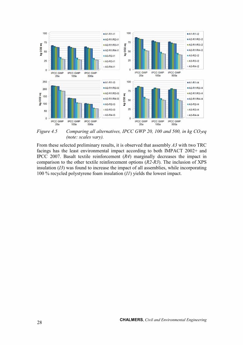
CHALMERS, Civil and Environmental Engineering
28
Figure 4.5 Comparing all alternatives, IPCC GWP 20, 100 and 500, in kg CO2eq
(note: scales vary). From these selected preliminary results, it is observed that assembly A3 with two TRC facings has the least environmental impact according to both IMPACT 2002+ and IPCC 2007. Basalt textile reinforcement (R4) marginally decreases the impact in comparison to the other textile reinforcement options (R2-R3). The inclusion of XPS insulation (I3) was found to increase the impact of all assemblies, while incorporating 100 % recycled polystyrene foam insulation (I1) yields the lowest impact.

CHALMERS, Civil and Environmental Engineering
29
5 Experimental Study and Numerical Modelling [Papers I & III]
An experimental study was conducted to investigate the load carrying capacity under bending stress, and overall structural behaviour of TRC in both one- and two-way action. The experimental study is presented in two major parts:
• Study A comprises of a pilot study of four-point bending testing of one-way TRC slabs reinforced by three different carbon textiles, namely Fine, Medium and Coarse, refer to Paper I.
• Study B consists of four-point bending testing of one-way TRC slabs reinforced by AR-glass, carbon and basalt textiles, as well as two-way TRC slabs subjected to a point load at the centre reinforced by AR-glass and basalt textiles, refer to Paper III. Pull-out tests of TRC specimens reinforced by AR-glass, carbon and basalt textiles were also conducted but their analysis is beyond the scope of this thesis.
All test specimens were casted at the Danish Technical Institute (DTI), where one-way slabs (Study A and B) and pull-out tests were also done, while two-way slab tests were carried out at Chalmers University of Technology. In Study B, due to project time constraints, the casting of all slabs had to be executed simultaneously; however, it could have been beneficial to test and evaluate the flexural behaviour of the one-way slabs prior to casting and testing of the large-scale two-way slabs in order to optimize the textile reinforcement ratio. Nevertheless, the possibility to do direct comparisons between the one-way and two-way slabs in Study B is increased, as concrete from the same batch was used.
Revealing basic properties and exploring options to implement in thin shell and façade structures were secondary aspects of interest for this study. Moreover, numerical models developed using finite element analysis software DIANA 9.4.4 with pre- and post-processor FX+ (TNO Diana, 2011) were used to further evaluate the experimental results. The experimental and numerical modelling results corresponding to Study A are discussed in Paper I, while the findings from experimental Study B are covered in Paper III.
5.1 Review The mechanical properties, in the form of flexural behaviour, of TRC are considered by Brameshuber (2006) to be insufficiently quantified. A multitude of characteristics, ranging from the textile and fine-grained concrete material selection to the reinforcement ratio, influence the expected behaviour of TRC. As previously mentioned in Section 2, a textile reinforcement yarn consists of multitudes of filaments which creates a complex heterogeneous structure. An uneven penetration of fine-grained concrete matrix occurring within an uncoated textile reinforcement yarn has led to the evaluation and characterization of the internal bond behaviour through means of numerical modelling. Textile reinforced concrete can be modelled on a structural level (macro), sectional detailed level (meso), material level (micro), or even through a combination of these aforementioned levels (multi-scale). Finite element modelling in macro (Holler et al., 2004), meso (Holler et al., 2004, Hegger et al., 2006, Häußler-Combe et al., 2007, Hartig et al., 2008), micro (Chudoba et al.,
CHALMERS, Civil and Environmental Engineering
30
2006, Vořechovský et al., 2006) and multi-scales (Lepenies et al., 2008, Peiffer, 2008) have been shown to be valid tools to investigate the behaviour of TRC; however, experimental results are undoubtedly needed to support and verify the results and allow for further model development (Brameshuber, 2006).
The load-bearing behaviour of TRC has been investigated using bending, shear, as well as uniaxial- and biaxial-tension tests (Brameshuber, 2006). For instance, four-point bending tests on TRC I-sections reinforced by AR-glass and carbon fabrics were conducted to quantify both bending and shear behaviour. The influence of varying the reinforcement ratios was also included in the study. It was found that TRC members subjected to bending stresses can yield higher flexural capacities compared to that from tensile tests. Essentially, bending stresses initiate transversal action on the textile yarns due to the beam’s curvature; which enhances the bond, particularly of the inner filaments. This phenomenon is, however, a function of the reinforcement ratio and textile mesh binding, e.g. tricot or chain. With an increasing reinforcement ratio, the tensile area also increases due to smaller crack spacing. The binding type can also play an important role, in the case of chain binding, the filaments are said to be initially compressed such that the effects from bending are negligible. Analytical models taking this bending effect into consideration are presented in (Brameshuber, 2006, Hegger et al., 2008a, Hegger et al., 2008b) and briefly mentioned in Section 2 of this thesis.
In another study, flexural testing of thin slabs reinforced by two layers of freely-laid AR-glass was executed, wherein procedures to measure the flexural behaviour were developed and the effect of the specimen thickness and fabric orientation were also investigated (Brameshuber, 2006). The load-displacement curve was characterized by initial linear stiffness up until first cracking, followed by a decrease in stiffness and a load increase up to four times that of the cracking load, and ending in a nearly plastic behaviour after reaching ultimate load. It was determined for specimens with the same amount of reinforcement that reducing the specimen thickness (11.4 to 7.6 mm) increased the fabrics ability (higher volume fraction per area) to distribute cracks; as such, the composite had a more ductile behaviour and higher strength. Furthermore, the fabric orientation which is a function of the machine and cross-machine directions was studied. Yarns inserted with a straight orientation into the mesh were found to result in higher load, as a more homogeneous load distribution can take place over the length of the yarn.
Four-point bending of 90 TRC specimens reinforced by a hybrid textile mesh of carbon (weft) and E-glass (warp) yarns was completed by Yin et al. (2013). This experimental setup only took into account the load-bearing capacity of the weft yarns. The specimens had dimensions of 490 mm x 100 mm x h x a; the height, h, and cover thickness, a, varied by 10 - 25 mm and 1, 3, 5 mm, respectively. After first cracking, it was discovered that as the concrete cover thickness decreased and inner lever increased, the stiffness and bearing capacity increased for any given mid-span deflection. Yin et al. (2013) state that a thinner concrete cover, i.e. 1 and 3 mm, improves the utilization of the textile in terms of crack restraint while ensuring adequate anchorage. Including polypropylene loose-fibres (1.0 kg/m3) was also found to improve the stiffness of the specimen after cracking due to effect of crack bridging.
Other efforts related to four-point bending testing on TRC specimens include, but are not limited to sandwich panels with rigid TRC facings as well as modular roof elements (Hegger et al., 2009). Furthermore, the bending behaviour of TRC applied as flexural strengthening to existing reinforced concrete (RC) has also been investigated
CHALMERS, Civil and Environmental Engineering
31
by means of four-point bending testing by (Bruckner et al., 2006, Weiland et al., 2011, Xu et al., 2011, Schladitz et al., 2012). For instance, it was observed that RC slabs strengthened with TRC present significant increase in load-bearing capacity and reduction in deflection compared to unstrengthened RC slabs (Schladitz et al., 2012).
One main advantage of using a textile mesh as reinforcement is such that the yarns can easily be orientated according to the direction of the tensile stresses. In the case of one-way bending, however, only the lateral yarns are fully activated and contribute to the flexural capacity. Since the typical configuration of a textile fibre mesh includes bi- or multi-directional yarns, it is of interest to effectuate the full-flexural capacity by means of testing slabs under two-way bending. It should also be taken into consideration that in a realistic application, e.g. facade panels, two-way action often governs.
Research regarding two-way bending behaviour of TRC, particularly in large scale, is limited in literature thus providing an opening to further investigate and expand the knowledge about this topic. Ajdukiewicz et al. (2009) compared the load-bearing behaviour of TRC plates (1200 x 1000 x 40 mm) reinforced by three different types of textiles, namely AR-glass, polyvinyl-alcohol (PVA) with polyvinyl chloride (PVC) coating and carbon with AR-glass (hybrid). A specimen reinforced by a steel mesh was used as a reference. A total of 12 plate specimens were simply-supported and subjected to bending by means of a concentrated force linearly distributed at mid-span until failure. The linear behaviour before first crack, defining the initial stiffness of the matrix, is said to be the most important aspect for practical applications according to Ajdukiewicz et al. (2009). This statement is considered to be valid for non-load bearing façade elements, for example, such that cracking is meant to be avoided primarily to preserve aesthetic appeal. Moreover, after first cracking is achieved, differing load-bearing behaviours are observed for each textile reinforcement type during the so-called post-cracking phase. The specimens reinforced by AR-glass fabrics had comparable initial stiffness and load-bearing capacity to that of the steel mesh reference specimen. The PVA with PVC coating and hybrid reinforcement types reached their maximum load-bearing capacity at the point of first cracking; thereafter, a sudden drop occurred followed by softening and ductile behaviour until failure (45 mm). Lastly, the ratio between the experimental bending capacity and calculated one were compared for each textile reinforcement material. It was found that the hybrid mesh was the most effective solution.
Papanicolaou et al. (2009) conducted experimental testing of two-way conventionally reinforced concrete (RC) slabs (with edge beams) strengthened by Textile Reinforced Mortar (TRM) overlays, which is synonymous to TRC. The effectiveness of flexural strengthening RC slabs using TRM overlays was explored in terms of strength and deformation capacity. In this study, specimens were tested under monotonic flexural loading at mid-span with displacement control. Both high-strength carbon fibre (1650 tex) and E-glass fibre (2400 tex) meshes were used as TRM overlays. As per Papanicolaou et al. (2009), one layer of carbon fibre mesh is equivalent to three layers of E-glass fibre mesh. Accordingly, the test specimens included: unstrengthened-control, one and two layers of carbon, and three layers of E-glass. The load-deflection response at mid-span, load-strain of steel reinforcement, as well as critical response values (i.e. first crack, steel yielding, maximum and ultimate capacity) were summarized for all specimens. The crack development and failure mode, which in all cases was flexural punching with debonding of TRM overlays, were also documented. Furthermore, a comparison between the maximum load and existing formulations for

CHALMERS, Civil and Environmental Engineering
32
flexure/shear interaction showed excellent agreement. In the end, TRM overlays were found to be an effective strengthening method, as the load-carrying capacity of RC slabs was observed to increase with an increase of fibre reinforcement ratio.
Mu et al. (2003) conducted an experimental study on the bending and punching shear strength of fibre-reinforced glass concrete slabs. The two-way bending test setup including a central patch load applied under displacement control. Focusing on two-way bending testing results in Mu et al. (2003), two groups of specimens were included: a) reinforced with short random fibres distributed over half of slab on tension side b) reinforced with fibre mesh. Three types of fibres were studied: AR-glass fibres (12.7 mm long), polyvinyl alcohol (PVA) fibres (6 mm long), and polypropylene fibres (12.7 mm long). The number of mesh layers, type of mesh structure (woven vs. knitted) and volume of short fibres were also varied. Mu et al. (2003) concluded that continuous fibre mesh is more effective than randomly distributed fibres, primarily due to its optimum placement, enhanced bond, and longer bridging length. This improved bridging caused more cracking in the specimen which, in turn, increased the ultimate load capacity. It was also observed that the effectiveness of short fibres is greater in two-way rather than one-way bending (18 % increase in ultimate strength vs. 10 %).
5.2 Study A (Paper I) In this study, thin one-way TRC slabs reinforced by three different carbon fibre textiles were prepared and tested under four-point bending at DTI. The test specimens had dimensions of 800 x 200 x 80 mm and were tested inversely according to Figure 5.1. The layer of textile reinforcement was fastened by the framework during casting, which slightly reduced the initial waviness of the mesh. Additional information regarding the test setup, specimen preparation, as well as relevant material data for fine-grained concrete and textile meshes can be retrieved from Paper I.
Figure 5.1 One-way slab geometry and test setup.
5.2.1 Experimental results The experimental results obtained from the four-point bending test for all three carbon textile mesh alternatives, Coarse, Medium and Fine, are presented respectively in Figure 5.2. Initial cracking arose at approximately 10 kN for all alternatives, which was followed by multiple through-going cracks until reaching failure. Delamination was the failure mode observed for both Medium and Fine specimens while textile
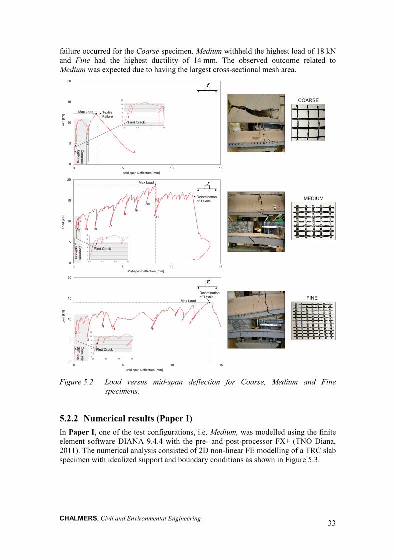
CHALMERS, Civil and Environmental Engineering
33
failure occurred for the Coarse specimen. Medium withheld the highest load of 18 kN and Fine had the highest ductility of 14 mm. The observed outcome related to Medium was expected due to having the largest cross-sectional mesh area.
Figure 5.2 Load versus mid-span deflection for Coarse, Medium and Fine
specimens.
5.2.2 Numerical results (Paper I) In Paper I, one of the test configurations, i.e. Medium, was modelled using the finite element software DIANA 9.4.4 with the pre- and post-processor FX+ (TNO Diana, 2011). The numerical analysis consisted of 2D non-linear FE modelling of a TRC slab specimen with idealized support and boundary conditions as shown in Figure 5.3.
0
5
10
15
20
0 5 10 15
Load
[kN
]
Mid-span deflection [mm]
Textile Failure
Max Load
0
2
4
6
8
10
12
0.0 0.5 1.0 1.5
First Crack
21
Concrete
Stiffness
Mid-span Deflection [mm]
Load
[kN
]
COARSE
0
5
10
15
20
0 5 10 15
Load
[kN
]
Mid-span deflection [mm]
<
0
2
4
6
8
10
12
0.0 0.5 1.0 1.5
First Crack
Max Load
Delamination of Textile
5 67
89
10
11
Concrete
Stiffness
3
42
1
Mid-span Deflection [mm]
Load
[kN
]
MEDIUM
0
5
10
15
20
0 5 10 15
Load
[kN
]
Mid-span deflection [mm]
Max Load
0
2
4
6
8
10
12
0.0 0.5 1.0 1.5
Delamination of Textile
45 6
First Crack
Concrete
Stiffness
21
3
Mid-span Deflection [mm]
Load
[kN
]
FINE
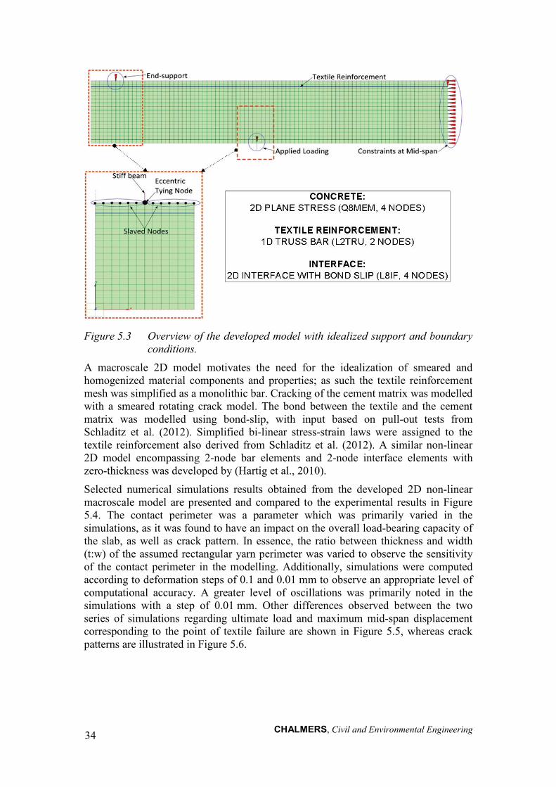
CHALMERS, Civil and Environmental Engineering
34
Figure 5.3 Overview of the developed model with idealized support and boundary
conditions. A macroscale 2D model motivates the need for the idealization of smeared and homogenized material components and properties; as such the textile reinforcement mesh was simplified as a monolithic bar. Cracking of the cement matrix was modelled with a smeared rotating crack model. The bond between the textile and the cement matrix was modelled using bond-slip, with input based on pull-out tests from Schladitz et al. (2012). Simplified bi-linear stress-strain laws were assigned to the textile reinforcement also derived from Schladitz et al. (2012). A similar non-linear 2D model encompassing 2-node bar elements and 2-node interface elements with zero-thickness was developed by (Hartig et al., 2010).
Selected numerical simulations results obtained from the developed 2D non-linear macroscale model are presented and compared to the experimental results in Figure 5.4. The contact perimeter was a parameter which was primarily varied in the simulations, as it was found to have an impact on the overall load-bearing capacity of the slab, as well as crack pattern. In essence, the ratio between thickness and width (t:w) of the assumed rectangular yarn perimeter was varied to observe the sensitivity of the contact perimeter in the modelling. Additionally, simulations were computed according to deformation steps of 0.1 and 0.01 mm to observe an appropriate level of computational accuracy. A greater level of oscillations was primarily noted in the simulations with a step of 0.01 mm. Other differences observed between the two series of simulations regarding ultimate load and maximum mid-span displacement corresponding to the point of textile failure are shown in Figure 5.5, whereas crack patterns are illustrated in Figure 5.6.

CHALMERS, Civil and Environmental Engineering
35
Figure 5.4 Load versus mid-span deflection from experimental results and
simulations (1:25, 1:50, 1:100 for step sizes of 0.1 mm (Left) and 0.01 mm (Right)).
Figure 5.5 Comparison of ultimate load versus contact perimeter (Left);
comparison of maximum mid-span displacement versus contact perimeter (Right). Experimental results and simulation results corresponding to step sizes of 0.1 and 0.01 mm are included.

CHALMERS, Civil and Environmental Engineering
36
Figure 5.6 Crack pattern (strain in x-direction) at textile failure versus
experimental results. The main failure mode observed in the experiments was in bending with the delamination of the textiles from the mortar or by the tensile failure of the textile. In the numerical analyses, however, only textile failure could be modelled. It was attempted to model a delamination failure in 2D by weakening the concrete elements surrounding the textile, but this was found to be ineffective. Perhaps incorporating stochastic properties of the filaments (Hartig et al., 2010) or even the development of a 3D model could exemplify more fitting failure behaviour. Moreover, the contact perimeter between the textile reinforcement mesh and the concrete matrix was found to be a sensitive modelling parameter. The appearance of cracks in Figure 5.6 is thought to be governed by how well the prescribed contact perimeter correlates with the yielded crack distance between loads. However, the crack pattern corresponding to the strain at textile failure appeared to vary for simulations having the same prescribed contact perimeter when changing the step size from 0.1 to 0.01 mm. Lastly, a reasonably good agreement was observed between calibrated numerical results (1:25, 0.1) and experimental results. A detailed methodology related to the development of the FE model and discussion can be found in Paper I.
5.3 Study B (Paper III) Thin one-way TRC slabs reinforced by AR-glass, carbon and basalt textiles were tested under four-point bending in Study B, refer to Figure 5.7. These slab specimens are similar to that shown above in Figure 5.1 with the exception of differing slab dimensions of 1000 x 200 x 50 mm. In addition, two mesh configurations illustrated in Figure 5.7 were studied: 1) whole mesh and 2) spliced mesh with overlap. The main reason for testing one-way specimens with a spliced mesh with overlap is to
1:20000 (0.1)
1:10000 (0.1)
1:500 (0.1)
1:200 (0.1)
1:10 (0.1)
1:1000 (0.1)
1:2 (0.1)
1:5 (0.1)
1:25 (0.1)
1:50 (0.1)
1:100 (0.1)
1:750 (0.1)
1:5000 (0.1)
12 4 35
5 12 34
1:1000 (0.01)
1:2 (0.01)
1:5 (0.01) 1:500 (0.01)
1:50 (0.01)
1:20000 (0.01)
1:10000 (0.01)
1:750 (0.01)
1:200 (0.01)
1:5000 (0.01)
1:100 (0.01)
1:25 (0.01)
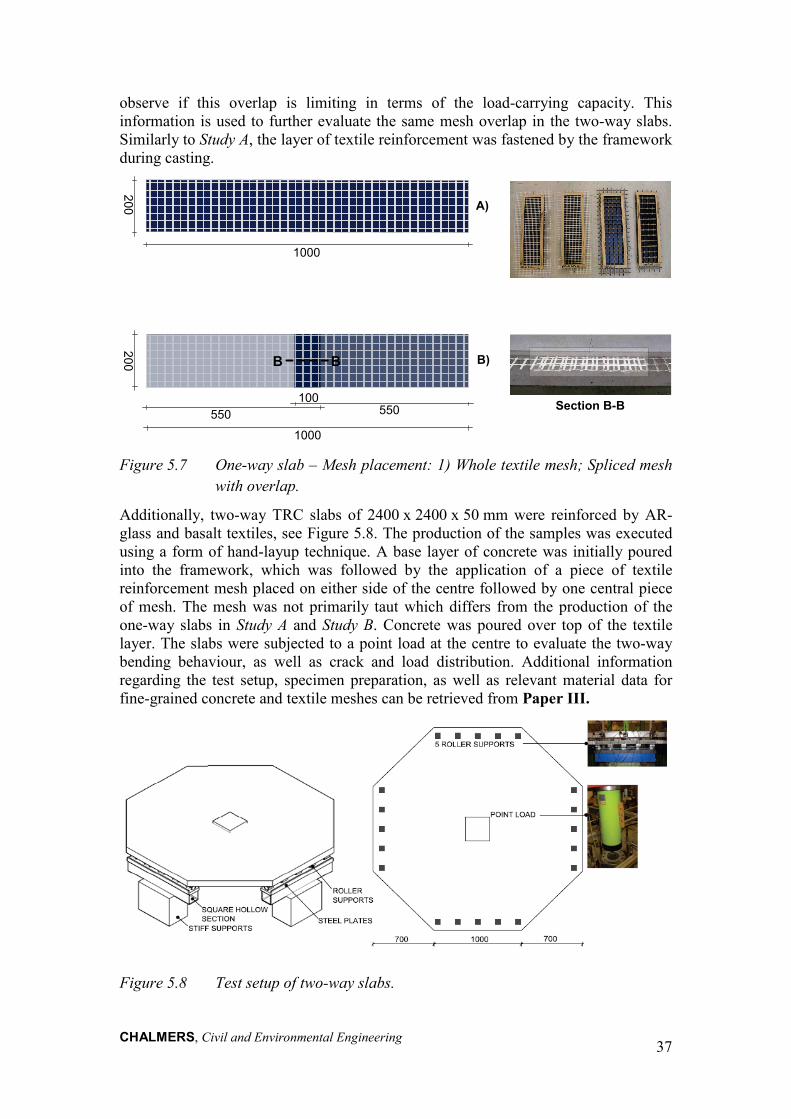
CHALMERS, Civil and Environmental Engineering
37
observe if this overlap is limiting in terms of the load-carrying capacity. This information is used to further evaluate the same mesh overlap in the two-way slabs. Similarly to Study A, the layer of textile reinforcement was fastened by the framework during casting.
Figure 5.7 One-way slab – Mesh placement: 1) Whole textile mesh; Spliced mesh
with overlap.
Additionally, two-way TRC slabs of 2400 x 2400 x 50 mm were reinforced by AR-glass and basalt textiles, see Figure 5.8. The production of the samples was executed using a form of hand-layup technique. A base layer of concrete was initially poured into the framework, which was followed by the application of a piece of textile reinforcement mesh placed on either side of the centre followed by one central piece of mesh. The mesh was not primarily taut which differs from the production of the one-way slabs in Study A and Study B. Concrete was poured over top of the textile layer. The slabs were subjected to a point load at the centre to evaluate the two-way bending behaviour, as well as crack and load distribution. Additional information regarding the test setup, specimen preparation, as well as relevant material data for fine-grained concrete and textile meshes can be retrieved from Paper III.
Figure 5.8 Test setup of two-way slabs.
200200 A)
550 550
1000
1000
100
B
Section B-B
B)B

CHALMERS, Civil and Environmental Engineering
38
5.3.1 Experimental results: one-way slabs The experimental results obtained from the four-point bending tests for the AR-glass, basalt and carbon TRC slab specimens are summarized in this section and evaluated in Paper III. Overall, the cracking load was observed to be equal to or slightly above 4 kN. The flexural behaviour of each specimen group was similar with minimal deviations. The selected textile mesh overlap (100 mm) appeared to be adequate to transfer the load across the overlap, as the common failure mode for all specimens was textile rupture. The load versus mid-span deflection relationships for the TRC slab specimens reinforced by AR-glass, basalt and carbon textile fibre mesh are provided along with final crack patterns and general observations, see Figure 5.9 to Figure 5.11, respectively.
Observations First cracking at
maximum load (4.0-4.8 kN) at deflection of 0.8-1.3 mm
Only one crack Abrupt stiffness
decrease in post-cracked state
Failure mode: textile rupture
Overlap (100 mm) OK
Figure 5.9 Load versus mid-span deflection and selected final crack patterns for AR-glass.
1Aa
1Ab
1Ac
1Asa
1Asb
1Asc

CHALMERS, Civil and Environmental Engineering
39
Observations First cracking at
maximum load (4.0-4.8 kN) for 1Ba, 1Bsb and 1Bs
Load could be slightly increased after cracking for 1Bb, 1Bc and 1Bsa
Small stiffness decrease in post-cracked state
More ductile than AR-glass (e.g. deflection at max load: 14.5 mm for 1Bb and 7.1 mm for 1Bc)
No. of cracks: 1-2 Failure mode:
textile rupture Overlap (100 mm)
OK
Figure 5.10 Load versus mid-span deflection and selected final crack patterns for basalt.
1Ba
1Bb
1Bc
1Bsa
1Bsb
1Bsc
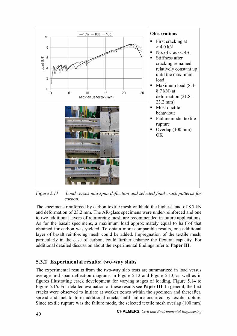
CHALMERS, Civil and Environmental Engineering
40
Observations First cracking at
> 4.0 kN No. of cracks: 4-6 Stiffness after
cracking remained relatively constant up until the maximum load
Maximum load (8.4-8.7 kN) at deformation (21.8-23.2 mm)
Most ductile behaviour
Failure mode: textile rupture
Overlap (100 mm) OK
Figure 5.11 Load versus mid-span deflection and selected final crack patterns for carbon.
The specimens reinforced by carbon textile mesh withheld the highest load of 8.7 kN and deformation of 23.2 mm. The AR-glass specimens were under-reinforced and one to two additional layers of reinforcing mesh are recommended in future applications. As for the basalt specimens, a maximum load approximately equal to half of that obtained for carbon was yielded. To obtain more comparable results, one additional layer of basalt reinforcing mesh could be added. Impregnation of the textile mesh, particularly in the case of carbon, could further enhance the flexural capacity. For additional detailed discussion about the experimental findings refer to Paper III.
5.3.2 Experimental results: two-way slabs The experimental results from the two-way slab tests are summarized in load versus average mid span deflection diagrams in Figure 5.12 and Figure 5.13, as well as in figures illustrating crack development for varying stages of loading, Figure 5.14 to Figure 5.16. For detailed evaluation of these results see Paper III. In general, the first cracks were observed to initiate at weaker zones within the specimen and thereafter, spread and met to form additional cracks until failure occurred by textile rupture. Since textile rupture was the failure mode, the selected textile mesh overlap (100 mm)
1Cc
1Ca
1Cb

CHALMERS, Civil and Environmental Engineering
41
appeared to be adequate for effective load transfer. It is worth stating that the results presented exclude support settlements as they were found to be relatively small (maximum of 0.4 mm) and thus could be considered as negligible. Also, lifting of the slab (maximum of 4.65 mm) did occur at given supports when the respective reaction force dropped to zero.
Observations
Pre-cracking: stiffness differences due to thickness discrepancies (2Asc thicker on average by 11 mm) Average max load 14.8 kN
at mid-span deflection 2 mm (2Asa and 2Asb) Max load 19.3 kN at mid-
span deflection 2.7 mm (2Asc) First cracking load =
ultimate load, Under-reinforced
Figure 5.12 AR-glass specimens – Load versus mid-span deflection (uncorrected for support settlement).
Observations
Pre-cracking: stiffness comparable between 2Bsa and 2Bsc
Average max load 17.3 kN at mid-span deflection 34.3 mm (2Bsa and 2Bsc)
Ultimate load > first cracking load, higher load-carrying capacity, ductile behaviour and more crack propagation than AR-glass specimens
Figure 5.13 Basalt specimens – Load versus mid-span deflection (uncorrected for support settlement).
To further analyse the failure behaviour, the development of the crack pattern and associated reaction forces for all specimens were examined in Paper III and selected specimens are presented here, refer to Figure 5.14 to Figure 5.16. The development of the crack pattern is depicted for three varying stages of loading which are indicated on a figure of the total reaction force per support line (summation of contribution from five rollers) versus deformation.

CHALMERS, Civil and Environmental Engineering
42
A
B
C
Observations
Reaction force distribution was initially even along each support line. Larger portion of reaction distributed to roller support in line with the crack. Reaction forces stabilized in final stages of loading causing peak reaction forces over
supports affected by cracking. Slight lifting took place where reaction forces were zero.
Figure 5.14 Crack pattern development for 2Asa.
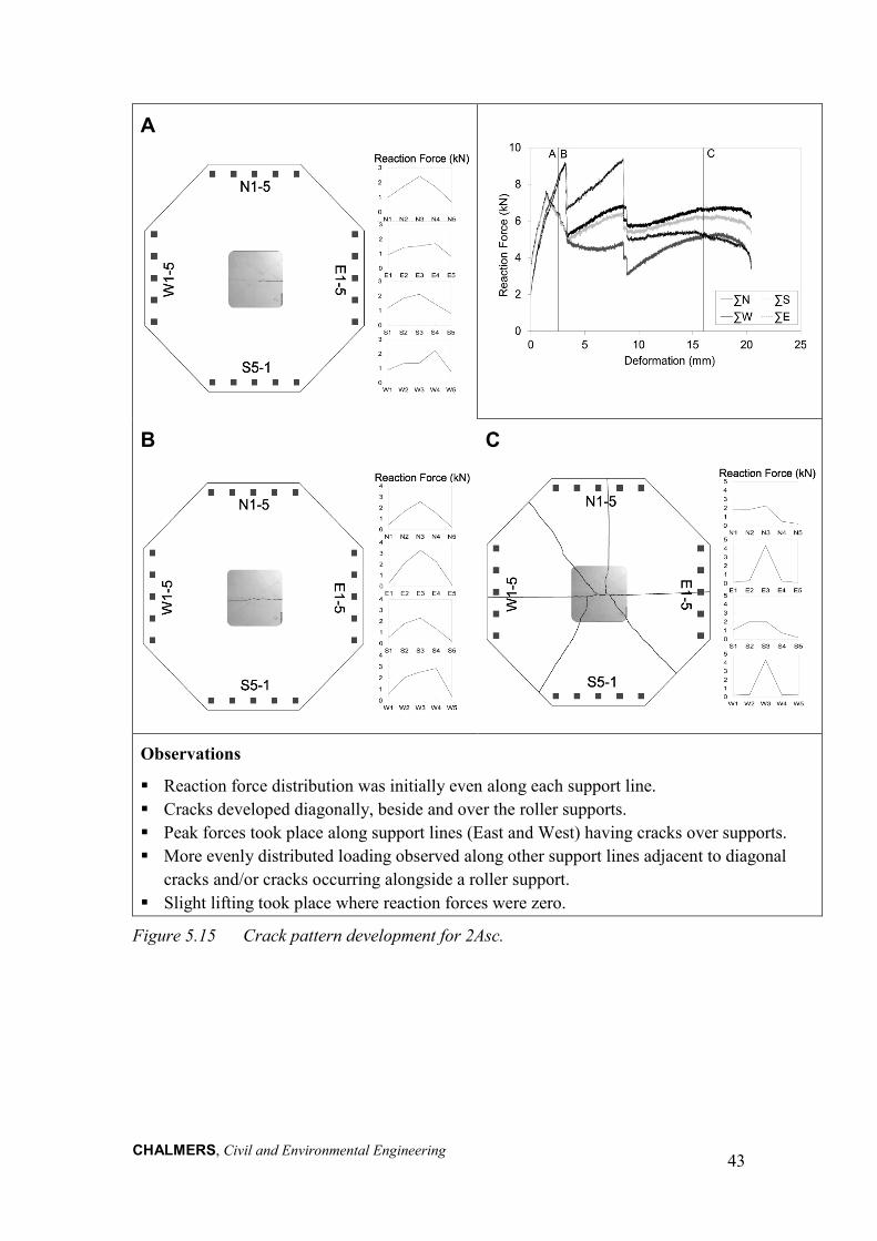
CHALMERS, Civil and Environmental Engineering
43
A
B
C
Observations
Reaction force distribution was initially even along each support line. Cracks developed diagonally, beside and over the roller supports. Peak forces took place along support lines (East and West) having cracks over supports. More evenly distributed loading observed along other support lines adjacent to diagonal
cracks and/or cracks occurring alongside a roller support. Slight lifting took place where reaction forces were zero.
Figure 5.15 Crack pattern development for 2Asc.

CHALMERS, Civil and Environmental Engineering
44
A
B
C
Observations
Reaction forces evenly distributed across all support lines at initial cracking. Cracks propagated diagonally and over a roller support (East). Support lines bordered by two diagonal cracks had reaction forces distributed along support
lines with max force at central roller supports (North and West). Relatively distinct peak reaction force arose over a roller support on the effected side where
the support line was mainly bounded by one diagonal crack (South). Clear peak reaction force occurred at the location of cracking over a roller support along
the East. Slight lifting took place where reaction forces were zero.
Figure 5.16 Crack pattern development for 2Bsa.

CHALMERS, Civil and Environmental Engineering
45
For the basalt reinforced slabs, the maximum load achieved was greater than the first cracking load, which was not the case for the AR-glass slabs. A greater number of cracks were formed in the basalt specimens, which also took place in the one-way beams reinforced by basalt. However, much variability was observed between the crack patterns for all specimens in the two-way slabs. Overall, the basalt specimens had slightly higher load-carrying capacity and ductile behaviour in comparison to the AR-glass specimens. Additional testing of two-way slab specimens would be recommended to improve the data sample, as well, the inclusion of carbon reinforced specimens could be worthwhile.
5.3.3 Analytical evaluation The experimental flexural capacities obtained for the one-way slabs are compared to analytical results computed using models applied to conventional reinforced concrete beams. It was of interest to compare the flexural capacity computed using both producer and rupture failure test data (from pull out tests in Study B) with that generated during the four-point bending tests. Refer to Paper III for more detailed information regarding the producer and rupture failure test data, the methodology used to analytically evaluate the flexural capacity, as well as an in depth discussion.
The analytical results for the one-way slabs were observed to slightly under predict the flexural capacity compared to the experimental results, see Figure 5.17. Due to the complex load-carrying behaviour of TRC, factors for the effectiveness of the textile reinforcement in a TRC member and lateral stresses in bending, for instance, need to be taken into account. These factors are highly dependent on the type of textile reinforcement and matrix composition and should be derived based on extensive test series.
Figure 5.17 Calculated versus experimental flexural capacities with indicated 1:1
ratio for each textile alternative.
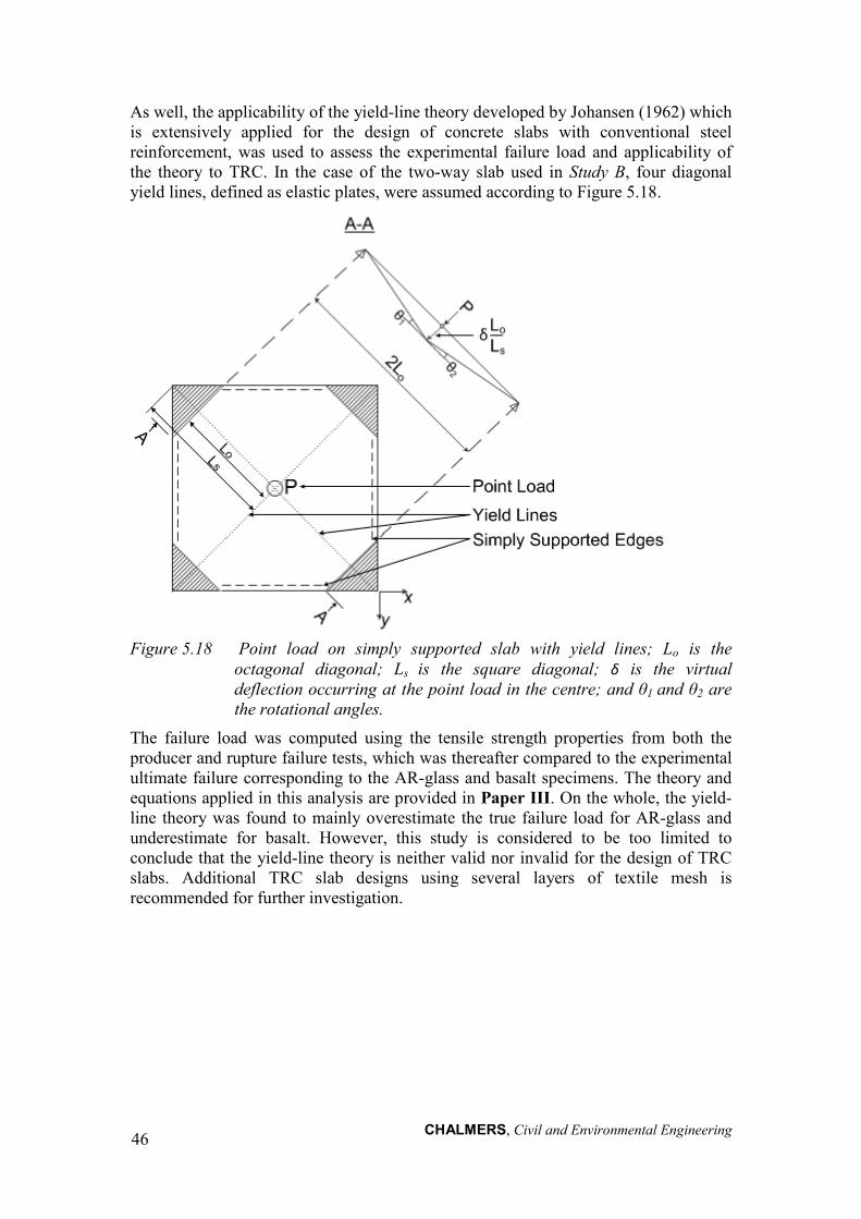
CHALMERS, Civil and Environmental Engineering
46
As well, the applicability of the yield-line theory developed by Johansen (1962) which is extensively applied for the design of concrete slabs with conventional steel reinforcement, was used to assess the experimental failure load and applicability of the theory to TRC. In the case of the two-way slab used in Study B, four diagonal yield lines, defined as elastic plates, were assumed according to Figure 5.18.
Figure 5.18 Point load on simply supported slab with yield lines; Lo is the
octagonal diagonal; Ls is the square diagonal; δ is the virtual deflection occurring at the point load in the centre; and θ1 and θ2 are the rotational angles.
The failure load was computed using the tensile strength properties from both the producer and rupture failure tests, which was thereafter compared to the experimental ultimate failure corresponding to the AR-glass and basalt specimens. The theory and equations applied in this analysis are provided in Paper III. On the whole, the yield-line theory was found to mainly overestimate the true failure load for AR-glass and underestimate for basalt. However, this study is considered to be too limited to conclude that the yield-line theory is neither valid nor invalid for the design of TRC slabs. Additional TRC slab designs using several layers of textile mesh is recommended for further investigation.

CHALMERS, Civil and Environmental Engineering
47
6 Conclusions 6.1 General conclusions The fundamental concepts and research background related to the novel building material, Textile Reinforced Concrete (TRC), were presented to provide adequate framework and motivation for this thesis. A qualitative assessment, paralleling common textile reinforcement materials to steel reinforcement, was concisely discussed (Paper II). A Life Cycle Assessment (LCA) was presented to quantify the sustainable potential of TRC in comparison to conventional reinforced concrete. TRC was observed to significantly decrease the cumulative energy demand and environmental impact of a reinforced concrete element, while basalt fibre reinforcement yielded the least cumulative energy demand and carbon fibre gave the least environmental impact.
Thanks to the non-corrosive reinforcement used in TRC, thin, light-weight and modular façade elements have been and continue to be the subject of sustainable product development. Through the HSB Living Lab case study, the environmental impact of common sandwich elements was based on the inclusion of thin TRC facings and variation of rigid insulation alternatives. Replacing steel reinforced concrete and massive concrete facings with thinner TRC facings (A3) decreased the environmental impact of the sandwich façade. The use of basalt fibre in TRC yielded a slightly lower impact in comparison to other fibres. Extruded polystyrene (XPS) insulation (I3) was found to increase the impact while 100 % recycled polystyrene foam insulation (I1) gave the lowest impact. An experimental study consisting of two pilot studies, Study A and B, was conducted to investigate the load carrying capacity under bending and overall structural behaviour of TRC in both one-way and two-way action. In Study A, the evaluation of one-way slabs reinforced by carbon textile meshes having varying densities was executed. All specimens reached initial cracking at approximately 10 kN, thereafter the formation of multiple through-going cracks took place until failure. The Medium carbon textile mesh alternative had the highest load carrying capacity as expected due to its larger cross-sectional area (Paper I). Furthermore, in Study B (Paper III), a comparison of the one-way flexural behaviour of slabs reinforced by one layer of carbon, AR-glass, and basalt showed that the carbon reinforced specimens withheld the highest load and deformation. In contrast, the AR-glass specimens were under-reinforced, while the basalt specimens yielded half of the carbon specimen’s capacity. The optimization of reinforcement ratio and inclusion of fibre coatings were suggested to obtain more comparable and enhanced results. As for two-way action, between basalt and AR-glass reinforced specimens, basalt had slightly higher load-carrying capacity and ductile behaviour. However, additional experiments are recommended to reach conclusive remarks.
A 2D non-linear model was developed in Study A for the Medium carbon textile mesh alternative and was verified by the corresponding experimental data. The textile reinforcement was simplified as a monolithic bar with bond-slip modelled to the concrete. The contact perimeter between the textile reinforcement mesh and the concrete matrix was found to be a sensitive modelling parameter which affected the load-bearing capacity and crack pattern. By defining a suitable contact perimeter (1:25), however, the actual crack pattern and load-bearing capacity could be simulated. The actual failure mode of delamination was not successfully modelled

CHALMERS, Civil and Environmental Engineering
48
here; further modelling using, for example, 3D elements could potentially yield the expected failure mode. (Paper I)
Analytical results computed using models tailored to conventional reinforced concrete structures were shown to generally underestimate the flexural capacity of TRC one-way slabs. As for the yield-line theory related to the two-way slabs, it was found to mainly overestimate the true failure load for AR-glass and underestimate for basalt. In general, experimental results are affected by a multitude of factors related to the separate materials in TRC, namely textile reinforcement and cementitious matrix, as well as the composite behaviour of TRC. Accordingly, much variability exists in the equation and extensive test series are needed in order to deduce conclusions.
Various production methods of TRC were explored in Study A and Study B. The insertion of the textile reinforcing mesh in the composite was varied such that the specimens were casted either by primarily fastening the mesh to the framework or by applying a form of hand-layup technique. Fastening the mesh allowed for precise mesh placement and minimization of dipping. Additionally, for the production of large-scale specimens, a spliced mesh configuration was tested. It was found that using a mesh overlap of 100 mm appeared to be adequate to transfer load in Study B.
6.2 Suggestions for future research At present, there is a large potential for the development of TRC elements, yet the textile reinforcement material data provided by the producers is limited and in many cases unreliable. In order to be able to adequately assess the mechanical behaviour and long-term performance, for example, appropriate and accurate testing data from the producers or manufacturers is essential. Further collaborative efforts between the producers and researchers could also be beneficial.
The future use of TRC will also be greatly dependent on the development of design and test standards. As of now, there is no specified, preferred or optimized textile reinforcement-matrix composite for any given application, such that the choice of materials remains virtually unbounded. Consequently, the formulation of general TRC design methods becomes challenging given the multitude of possible variables. In the case of individual TRC applications, experimental studies including large sample sizes are still needed to acquire approval.
The following prospective research areas are suggested:
• Develop and optimize TRC in the form of durable and sustainable façade panels for new building and renovation projects. This research will investigate: material selection, durability of the system, mechanical properties and FE modelling.
→ Evaluate the durability of TRC exposed to severe heat and moisture environmental conditions.
→ Perform LCA analyses covering the entire life-cycle of TRC panels using quantified long-term behaviour to identify potential paybacks.
→ Perform large-scale structural testing of developed façade panels. → Develop FE models verified by experimental results for the purpose of
design and standardization. • Further investigate and recommend TRC design methods for common
applications.

CHALMERS, Civil and Environmental Engineering
49
7 References Ajdukiewicz A., Kotala B. and Węglorz M. (2009): Application of non-metallic
fabrics as reinforcement in thin-walled precast concrete members. Architecture, Vol. 2 (2), pp. 57-66.
Brameshuber W. (2006): Report 36: Textile Reinforced Concrete-State-of-the-Art Report of RILEM TC 201-TRC.36. RILEM publications.
Bruckner A., Ortlepp R. and Curbach M. (2006): Textile reinforced concrete for strengthening in bending and shear. Materials and Structures, Vol. 39 (8), pp. 741-748.
Büttner T., Keil A., Orlowsky J., et al. (2009): Einsatz von Polymeren in Textilbeton–Entwicklung polymermodifizierter Betone und Einflüsse auf die Dauerhaftigkeit. Textilbeton Theorie und Praxis. Tagungsband zum, Vol. 4.
Büttner T., Orlowsky J. and Raupach M. (2011): Enhancement of the durability of AR-glass reinforcement due to an epoxy-impregnation. Erhöhung der Dauerhaftigkeit textiler Beton-Bewehrungen durch Epoxidharztränkung, Vol. 88 (5), pp. 263-270.
Chudoba R., Vořechovský M. and Konrad M. (2006): Stochastic modeling of multi-filament yarns. I. Random properties within the cross-section and size effect. International journal of Solids and Structures, Vol. 43 (3), pp. 413-434.
Cripps D. (2013): Woven Fabrics [Online]. Available: http://www.netcomposites.com/guide/wovenfabrics/40 [Accessed July 18, 2013].
Cuypers H., Orlowsky J., Raupach M., et al. (2007): Durability aspects of AR-glass-reinforcement in textile reinforced concrete, Part 2: Modelling and exposure to outdoor weathering. Advances in Construction Materials, (pp. 389-395), Springer Berlin Heidelberg.
Domone P. and Illston J. (2010): Construction materials: their nature and behaviour. Taylor & Francis.
EN 1992. (2004): Eurocode 2: Design of Concrete Structures: Part 1-1: General Rules and Rules for Buildings. British Standards Institution.
European Commission. (2013): European Reference Life Cycle Database 3.0 (ELCD). Joint Research Centre - Institute for Environment and Sustainability http://elcd.jrc.ec.europa.eu/ELCD3/.
Fydro. (2012): Dinamic Creative Concrete Cladding [Online]. Available: http://www.dinamicccc.com/ [Accessed February 5, 2013].
Förster T. and Mäder E. (2011): Performance of Modified Basalt Fibres. In: Proceedings of the 18th International Conference on Composite Materials (ICCM18), Korean Society for Composite Materials.
Förster T., Plonka R., Scheffler C., et al. (2010): Challenges for Fibre and Interphase Design of Basalt Fibre Reinforced Concrete. In: 2nd ICTRC-Textile Reinforced Concrete. International RILEM Conference on Material Science (MatSci), Aachen.

CHALMERS, Civil and Environmental Engineering
50
Graham P. (2009): Building ecology: First principles for a sustainable built environment. Wiley. com.
Hartig J. and Häußler-Combe U. (2010): A model for the uniaxial tensile behaviour of Textile Reinforced Concrete (TRC) covering effects at the micro and meso scales. In: Proceedings of ECF18, Dresden.
Hartig J., Häußler-Combe U. and Schicktanz K. (2008): Influence of bond properties on the tensile behaviour of Textile Reinforced Concrete. Cement and Concrete Composites, Vol. 30 (10), pp. 898-906.
Hartig J., Jesse F. and Häußler-Combe U. (2009): Influence of different mechanisms on the constitutive behaviour of textile reinforced concrete. In: 4th Colloquium on Textile Reinforced Structures (CTRS4).
Hegger J., Goralski C. and Kulas C. (2011a): A pedestrian bridge made of textile reinforced concrete. Schlanke Fußgängerbrücke aus Textilbeton, Vol. 106 (2), pp. 64-71.
Hegger J. and Horstmann M. (2009): Light-weight TRC sandwich building envelopes. Excellence in Concrete Construction through Innovation, Taylor & Francis.
Hegger J., Kulas C. and Horstmann M. (2011b): Realization of TRC facades with impregnated AR-glass textiles. Key Engineering Materials, Vol. 466, pp. 121-130.
Hegger J., Kulas C., Schneider H., et al. (2010): TRC Pedestrian Bridge-Design, Load-bearing Behavior and Production Processes of a Slender and Light-weight Construction. In: International RILEM Conference on Material Science: RILEM Publications SARL, 353-364.
Hegger J., Schneider H., Voss S., et al. (2008a): Dimensioning and application of textile-reinforced concrete. ACI Special Publication, Vol. 250.
Hegger J., Will N., Bruckermann O., et al. (2006): Load–bearing behaviour and simulation of textile reinforced concrete. Materials and Structures, Vol. 39 (8), pp. 765-776.
Hegger J. and Voss S. (2008b): Investigations on the bearing behaviour and application potential of textile reinforced concrete. Engineering Structures, Vol. 30 (7), pp. 2050-2056.
Hegger J., Zell M. and Horstmann M. (2008c): Textile Reinforced Concrete–Realization in applications. In: proceedings: International fib Symposium Tailor Made Concrete Structures: New Solutions For Our Society, 357-362.
Holler S., Butenweg C., Noh S. Y., et al. (2004): Computational model of textile-reinforced concrete structures. Computers & Structures, Vol. 82 (23-26), pp. 1971-1979.
Horstmann M. and Hegger J. (2011): Sandwich façades made of Textile Reinforced Concrete - Experimental investigations. Sandwichfassaden aus Textilbeton - experimentelle Untersuchungen, Vol. 88 (5), pp. 281-291.
Häußler-Combe U. and Hartig J. (2007): Bond and failure mechanisms of textile reinforced concrete (TRC) under uniaxial tensile loading. Cement and Concrete Composites, Vol. 29 (4), pp. 279-289.

CHALMERS, Civil and Environmental Engineering
51
Insu-Shell-Projekt LIFE. (2009): Life insu-Shell-Projekt • Institut Für Textiltechnik Der Rwth Aachen [Online]. Available: http://www.life-insushell.de/en/das-projekt.html [Accessed December 14, 2012].
Johansen K. W. (1962): Yield-line theory. Cement and Concrete Association London.
Kibert C. J. (2012): Sustainable construction: green building design and delivery. Wiley.com.
Kulas C., Schneider M., Will N., et al. (2011): Ventilated façade structures made of textile reinforced concrete - Structural behavior and construction. Hinterlüftete Vorhangfassaden aus Textilbeton: Tragverhalten und Ausführung, Vol. 88 (5), pp. 271-280.
Lepenies I. G., Richter M. and Zastrau B. W. (2008): A Multi-Scale Analysis of Textile Reinforced Concrete Structures. PAMM, Vol. 8 (1), pp. 10553-10554.
Losch E. D., Hynes P. W., Andrews Jr R., et al. (2011): State of the Art of Precast/Prestressed Concrete Sandwich Wall Panels. PCI Journal, p. 1.
Mahadevan M. G. (2009): Textile Spinning, Weaving and Designing. Chandigarh, IND. Global Media.
Malaga K., Tammo K., Flansbjer M., et al. (2012): Textile reinforced concrete sandwich panels. In: International FIB Symposium 2012, Stockholm, Sweden.
Mechtcherine V. (2012): Towards a durability framework for structural elements and structures made of or strengthened with high-performance fibre-reinforced composites. Construction and Building Materials, Vol. 31, pp. 94-104.
Mehta P. K. (2001): Reducing the environmental impact of concrete. Concrete international, Vol. 23 (10), pp. 61-66.
Mu B. and Meyer C. (2003): Bending and punching shear strength of fiber-reinforced glass concrete slabs. ACI Materials Journal-American Concrete Institute, Vol. 100 (2), pp. 127-132.
Möller B., Graf W., Hoffmann A., et al. (2005): Numerical simulation of RC structures with textile reinforcement. Computers & Structures, Vol. 83 (19–20), pp. 1659-1688.
Nmai C. K. and Suchorski D. M. (2006): Reinforcement for Concrete—Materials and Applications. ACI Education Bulletin E2-00. Committee E-701, Materials for Concrete Construction, Reapproved 2006.
Orlowsky J. and Raupach M. (2011): Textile reinforced concrete-from research to application. Cement Wapno Beton, Vol. 16 (6), pp. 323-331.
Orlowsky J., Raupach M., Cuypers H., et al. (2005): Durability modelling of glass fibre reinforcement in cementitious environment. Materials and Structures, Vol. 38 (2), pp. 155-162.
Ortlepp R. and Curbach M. (2009): Strengthening of Columns using Textile Reinforced Concrete (TRC). Beton- Und Stahlbetonbau, Vol. 104 (10), pp. 681-689.
Ortlepp R., Curbach M. and Weiland S. (2008): Rehabilitation and strengthening of a hypar concrete shell by textile reinforced concrete. Excellence in Concrete Construction through Innovation, Taylor & Francis.

CHALMERS, Civil and Environmental Engineering
52
Ortlepp R., Schladitz F. and Curbach M. (2011): Textilbetonverstärkte Stahlbetonstützen. Beton- Und Stahlbetonbau, Vol. 106 (9), pp. 640-648.
Papanicolaou C., Triantafillou T., Papantoniou I., et al. (2009): Strengthening of two-way reinforced concrete slabs with Textile Reinforced Mortars (TRM). In: Proc. of the 4th Colloquium on Textile Reinforced Structures (CTRS4) und zur, 409-420.
Parnas R., Shaw M. T. and Liu Q. (2007): Basalt Fiber Reinforced Polymer Composites. NETCR63, The New England Transportation Consortium.
Pease B. J. (2010): Influence of concrete cracking on ingress and reinforcement corrosion,. Ph.D. Thesis, Department of Civil Engineering, Technical University of Denmark.
Peiffer F. (2008): Framework for adaptive simulations applied to textile reinforced concrete. Ph.D. thesis, RWTH Aachen University.
PRé Consultants. (2010): SimaPro 7 Database Manual, Methods Library v.2.4. http://www.pre-sustainability.com/download/DatabaseManualMethods_oct2010.pdf.
Purnell P. (1998): The durability of glass fibre reinforced cements made with new cementitious matrices. Ph.D. Thesis, Aston University.
Raupach M., Orlowsky J. and Büttner T. (2011): Verbesserung der Dauerhaftigkeit von Textilbeton mittels Polymeren-Materialauswahl und Langzeitprognose. Techn. Univ., SFB 528.
Saertex. (2013): Saertex - Fibre Properties [Online]. Available: http://www.saertex.com/produkt_technik/produkte/fasereigenschaften/ [Accessed February 5, 2012].
Saint-Gobain Vetrotex. (2011): Saint-Gobain Vetrotex - Technical Information [Online]. Available: http://www.vetrotextextiles.com/TechnicalInformation [Accessed January 14, 2012].
Scheffler C., Förster T., Mäder E., et al. (2009a): Aging of alkali-resistant glass and basalt fibers in alkaline solutions: Evaluation of the failure stress by Weibull distribution function. Journal of Non-Crystalline Solids, Vol. 355 (52), pp. 2588-2595.
Scheffler C., Gao S., Plonka R., et al. (2009b): Interphase modification of alkali-resistant glass fibres and carbon fibres for textile reinforced concrete I: Fibre properties and durability. Composites Science and Technology, Vol. 69 (3), pp. 531-538.
Scheffler C., Gao S., Plonka R., et al. (2009c): Interphase modification of alkali-resistant glass fibres and carbon fibres for textile reinforced concrete II: Water adsorption and composite interphases. Composites Science and Technology, Vol. 69 (7), pp. 905-912.
Schladitz F., Frenzel M., Ehlig D., et al. (2012): Bending load capacity of reinforced concrete slabs strengthened with textile reinforced concrete. Engineering Structures, Vol. 40 (0), pp. 317-326.
CHALMERS, Civil and Environmental Engineering
53
Schladitz F., Lorenz E., Jesse F., et al. (2009): Strengthening of a barrel-shaped roof using textile reinforced concrete. In: IABSE Symposium Report: International Association for Bridge and Structural Engineering, 1-10.
Shaeffer R. (1992): Reinforced Concrete: Preliminary Design For Architects And Builders Author: RE Shaeffer, Publisher: Mcgraw-Hill Colleg.
Smarter Building Systems. (2010): Smarter Building Systems [Online]. Available: http://www.smarter-building-systems.com/smarter-building-basalt-faqs.html [Accessed September 10, 2012].
Stamm K. and Witte H. (1974): Sandwichkonstruktionen: Berechnung, Fertigung, Ausführung.Vol. 3. Springer.
Swiss Centre for Life Cycle Inventories. (2013): EcoInvent v3.0. http://www.ecoinvent.org/.
TNO Diana. (2011): Finite Element Analysis User's Manual - release 9.4.4. TNO.
Tomoscheit S., Gries T., Horstmann M., et al. (2011): Project Life INSUSHELL: Reducing the Carbon Footprint in Concrete Construction. International Journal of Sustainable Building Technology and Urban Development, Vol. 2 (2), pp. 162-169.
Van de Velde K., Kiekens P. and Van Langenhove L. (2003): Basalt fibres as reinforcement for composites. In: Proceedings of 10th international conference on composites/nano engineering, University of New Orleans, New Orleans, LA, USA, 20-26.
Wei B., Cao H. and Song S. (2010): Tensile behavior contrast of basalt and glass fibers after chemical treatment. Materials & Design, Vol. 31 (9), pp. 4244-4250.
Weiland S., Lorenz E., Ch H., et al. (2011): Flexural strengthening of RC-structures by textile reinforced concrete in practical application. Concrete Solutions 2011, CRC Press.
Williams Portal N., Lundgren K., Wallbaum H., et al. (2013): Sustainable Potential of Textile-Reinforced Concrete. Submitted to ASCE Journal of Materials in Civil Engineering.
Vořechovský M. and Chudoba R. (2006): Stochastic modeling of multi-filament yarns: II. Random properties over the length and size effect. International journal of Solids and Structures, Vol. 43 (3), pp. 435-458.
Wulfhorst B., Maetschke O., Osterloh M., et al. (2006): Textile Technology. Hanser Publishers.
Xu S., Yin S. and Cai X. (2011): Investigation on the flexural behavior of reinforced concrete beam strengthened with textile-reinforced concrete. Tumu Gongcheng Xuebao/China Civil Engineering Journal, Vol. 44 (4), pp. 23-34.
Yin S., Xu S. and Li H. (2013): Improved mechanical properties of textile reinforced concrete thin plate. Journal of Wuhan University of Technology-Mater. Sci. Ed., Vol. 28 (1), pp. 92-98.