suspended footbridge final design report tucuecito,...
TRANSCRIPT
Suspended Footbridge Final Design Report
Tucuecito, Panama 2015
Penn State Student Chapter of Bridges to Prosperity
113 Hammond Building
University Park, PA 16802
Website: http://asce.pennstatebridgestoprosperity.org
Primary Design Contact: [email protected]

2
Table of Contents
1.0 INTRODUCTION................................................................................................................... 3
2.0 DESIGN OBJECTIVE ........................................................................................................... 3
3.0 SITE VISIT.............................................................................................................................. 4
3.1 Topographical Survey .......................................................................................................... 4
3.2 Potential Suppliers ................................................................................................................ 4
3.3 Community Interviews.......................................................................................................... 4
4.0 DESIGN CONSTRAINTS ..................................................................................................... 5
5.0 DESIGN PROCESS ................................................................................................................ 5
5.1 Loads ..................................................................................................................................... 6
5.2 Cable Selection and clamps .................................................................................................. 6
5.3 Anchor and Tower Selection ................................................................................................ 7
5.4 Additional Checks ................................................................................................................. 7
5.5 Suspender Design.................................................................................................................. 7
5.6 Wood Crossbeam and Decking Design ................................................................................ 7
Appendix A: Survey and Site Data ................................................................................................ 9
Appendix B: Calculations ............................................................................................................ 17
Appendix C: Design Calculation Tables ..................................................................................... 19
Appendix D: Site Specific Bridge Drawings ............................................................................... 23

3
1.0 INTRODUCTION
This report details the design rationale for the suspended footbridge to be constructed by Penn
State Bridges to Prosperity in the community of Tucuecito, Panama from May 13, 2015 to June
13, 2015. Site layout was approved for Tucuecito in December 2014. Four students traveled to
Tucuecito in June 2014 to interview community members on the need for a bridge and to gather
site data used to create the design of the suspended footbridge.
The community of Tucuecito is located over an hour drive north of Penonome – refer to App A,
Fig 1 and 2 for map of area. The Rio Tucue, located at the edge of Tucuecito, floods frequently
and isolates the community from healthcare, education and markets. The Rio Tucue is shown in
App A, Fig 3 as it runs by Tucuecito. The existing crossing point for the Rio Tucue is the road
leading from Tucuecito to Penonome that crosses the river on a concrete slab sitting on the river
bed. This crossing is the only entrance to the community and is shown in App A, Fig 4. During
normal river flow community members must walk through the water flowing over the concrete
slab, however the rainy season lasts from June to November when heavy rainfall increases the
depth and velocity of the water flow. The crossing point of the river usually takes two to three
hours maximum to flood but twice it has flooded in less than an hour. Flooding makes crossing,
particularly for children, dangerous, if not impossible.
The proposed footbridge will eliminate this problem, providing safe travel to healthcare,
education and food. The closest clinic to Tucuecito, the Centro de Salud de Tuabre, is a 2.5 hour
walk from the community. Several children from the community attend high school in Penonome
along with two students who attend college also in Penonome. The Tucuecito community has
three small stores but they only carry dry food. To get other types of food residents are required
to travel to Penonome over the river. The proposed bridge, designed by Penn State Bridges to
Prosperity, is in partnership with the non-profit organization Bridges to Prosperity (B2P). This
report details the bridge design process, as well as a structural design.
2.0 DESIGN OBJECTIVE
The objective is to design a constructible, durable, and safe pedestrian bridge to cross the Rio
Tucue in Tucuecito, Panama in accordance with the Bridges to Prosperity Suspended Bridge
Manual, 4th edition. The bridge will see pedestrian, animal and bicycle traffic. The Penn State
B2P Chapter proposes our design of a cable-supported, pedestrian bridge for Tucuecito to
eliminate the risks associated with flooding that prevent travel to school, health facilities, and
markets. The proposed bridge will be located 25 meters upstream from the existing crossing
point.

4
3.0 SITE VISIT
Penn State Bridges to Prosperity conducted a site inspection at Tucuecito in June 2014 to
accomplish several objectives:
Complete a topographical survey of the site
Coordinate and procure suppliers and materials for construction
Interview community members to determine if there is a need for a new bridge and to
discuss community participation in the construction of the proposed bridge
3.1 Topographical Survey
Penn State Bridges to Prosperity used an automatic level to survey the proposed site and create a
profile view along the center line of the bridge, shown in App A, Fig 5. The survey points from
the proposed bridge site are shown in App A, Table 1. The proposed bridge’s tower-to-tower
span is 29.9 meters. The high water level, determined by interviews with community members, is
approximately 2.9 meters below the calculated low point of the proposed bridge under full
deflection as shown in App A, Fig 6. The calculations that determined the tower-to-tower span
and freeboard can be found in Appendix B.
3.2 Potential Suppliers
As a gold level university project, Penn State Bridges to Prosperity is not responsible for
securing in-country supplies and construction materials. B2P Program Manager, Jake Moriarty,
will locate and procure all supplies and materials needed for the project. There is a road from
Penonome to Tucuecito that will allow supplies and materials to be transported to the bridge site
via vehicles.
3.3 Community Interviews
In addition to performing a topographical survey of Tucuecito, Penn State B2P members also
conducted a meeting with the community during the site trip. Members had the chance to
interview the president of the community during this meeting where she mentioned many times
that the flooding caused by the heavy rain blocked the only entrance into the community. Also,
the heavy rain can prevent community members from returning home because the flooding
blocks a section of the community. Due to these two blockages an internal and external bridge
were desired by the community. Many community members fear that one day someone will get
bitten by a poisonous snake and will not have access to proper medical care due to the
impassable river conditions. Also, previous floods have prevented food importation. During the
5
community meeting many men from the community were willing to put in the work for the
necessary external bridge.
4.0 DESIGN CONSTRAINTS
As stated in the Bridges to Prosperity design manual there are several design constraints that
require consideration during the beginning of the design process.
First, the bridge had to be designed near the existing crossing point of the river. This is to
accommodate the familiarity and function of the community with the existing crossing point. The
distance between the proposed bridge and the existing crossing point will be approximately 25
meters.
Second, the bridge had to be designed at a location where there will be sufficient freeboard but
that avoids trees and other obstacles when it comes time to start construction. The bridge has
been located to avoid as many trees and shrubs as possible in this heavily vegetated area (see
App A, Fig 7.)
Finally, the proposed bridge must be able to be constructed using predominantly local materials
and labor. Local materials are used to reduce the cost of transporting materials and allow for
easier accessibility of material. The bridge construction is designed to be built with minimal
skilled labor so we can rely on the community members to provide the majority of the labor
force. This not only helps control the cost of the bridge but also empowers the community
members, which is a goal of B2P.
5.0 DESIGN PROCESS
Throughout this report the standard B2P convention of standing downstream of the bridge and
looking upstream to determine left and right is used. This view with the proposed bridge
placement can be seen in App A, Fig 8. Using the data gathered from the survey a profile view
of the bridge was created, App A, Fig 5. The number of tiers was then calculated to achieve the
required freeboard (Appendix B.) The Cable Lookup Tool, App C, Table 1, was used to
calculate the size and number of cables required for the span. With the number of tiers
determined along with the span being set by the location of the abutments, the construction
drawings in Appendix D were chosen.
In the original survey the point marked for the left side abutment was located 2.0 meters
horizontally from the edge of the slope. The B2P manual specifies that abutments be located 3.0
meters from the edge of an exposed soil slope. For the bridge design to meet the given

6
constraints, the abutment was moved 1.0 meter farther south (away from the river bank) as
shown in App A, Fig 9. The slope between points J and K in App A, Fig 5 was calculated and
used to adjust the elevation of the new abutment point. The table of survey points, App A, Table
1, was then adjusted to show this change.
The layout of the road and approach wall also creates potential erosion issues with runoff, which.
There is a drainage ditch on the west side of the road by the left abutment, App A, Fig 10. The
ditch cuts away from the road to drain in the river at the proposed location of the approach wall.
This would cause water to flow against the stone approach wall and erode the soil under it
causing a possible collapse of the wall. Penn State Bridges to Prosperity’s solution to this is to
move the location of the drainage ditch as it cuts away from the road, as shown in App A, Fig
11. The new drainage ditch will cut away from road above the anchor to avoid the entire bridge.
The proximity of the approach wall to the road was a concern during site layout. From
discussions with the B2P in country manager it was determined not to be an issue because of the
driving style in Panama. Drivers are very careful not to damage their vehicles since they have to
pay for damages to company vehicles. Also the road does not see much traffic as it ends in
Tucuecito. The approach wall next to the road will be constructed with added width in the small
chance that a vehicle would collide with it.
The freeboard for the proposed bridge is slightly under the standard set by B2P. To increase the
freeboard the foundation of the left abutment will be raised so that 0.15 meters is exposed,
instead of leaving the top of the foundation level with the ground. This was discussed with B2P
during the first TAB call and Penn State Bridges to Prosperity was told the modification would
make the freeboard acceptable.
5.1 Loads
The Bridges to Prosperity manual requires the chapter to consider live loads, dead loads, and
wind loads acting on the bridge, App C, Table 2. The loads are taken from the B2P manual. The
dead load is 0.98 kN/m, the live load is 4.07 kN/m, and the wind load is 0.29 kN/m. The
controlling load combination is the dead load plus the live load plus the wind load, which gives a
distributed load of 5.34 kN/m.
5.2 Cable Selection and clamps
The cable that is available for this project is 1 1/8 in. diameter steel cable. The cable is repurposed
cable from shipping docks. Using the Bridges to Prosperity look-up tool, App C, Table 1, it was
determined that three walkway cables and two handrail cables are sufficient for a 29.9 meter
span. Using a breaking strength of 108,000 pounds and a factor of safety of 3, the maximum span
allowed for three walkway cables is 89 meters. Each cable will have a length of 68.6 meters. The

7
number of drop-forged clamps that will be used for each 1 1/8 inch diameter cable is 6. The
clamps should be spaced every 144 mm. The torque required to tighten these clamps is 225 foot
– lbs. Therefore, a total of 60 drop-forged clamps are needed for this project. All of this can be
seen in App C, Table 3.
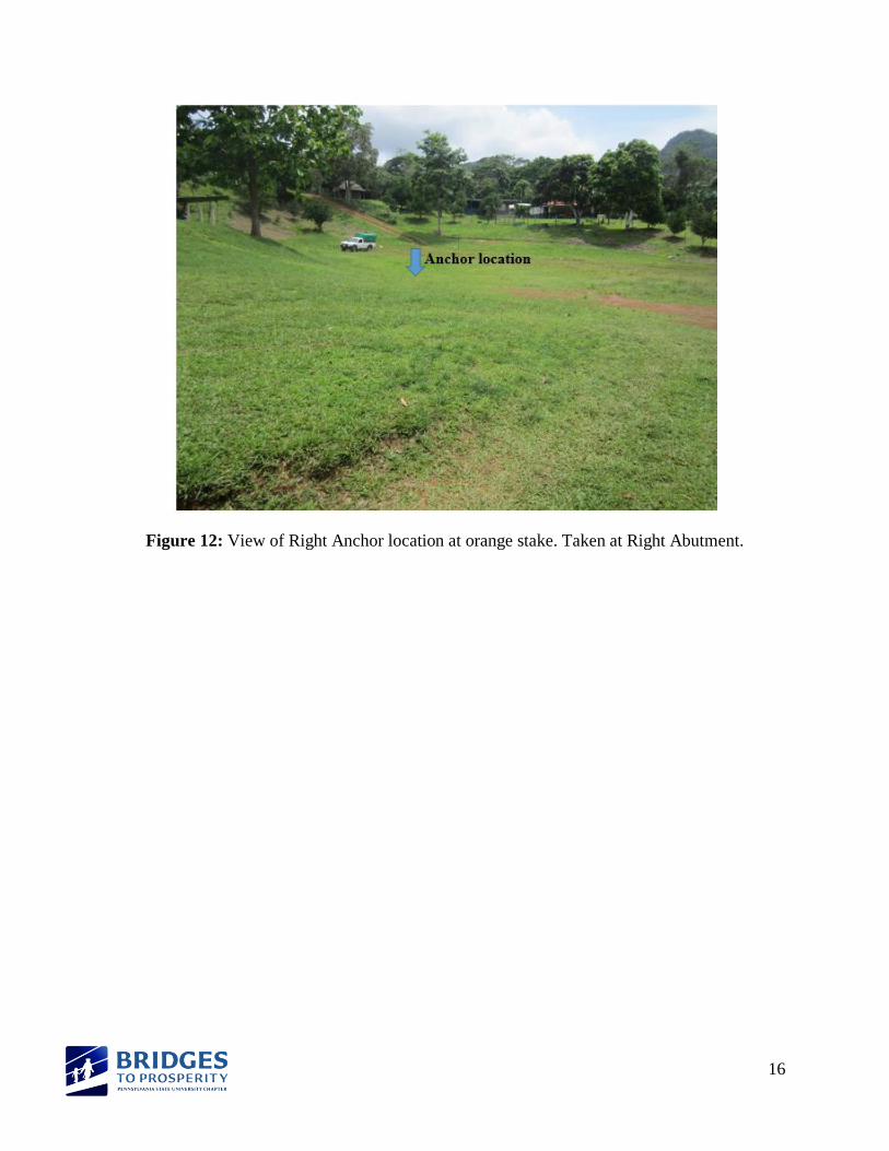
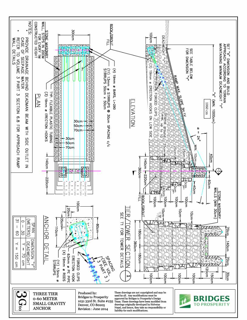
5.3 Anchor and Tower Selection
The proposed anchors are located in soil, App A, Fig 12, therefore a gravity anchor is most
appropriate. The B2P manual is used to determine the appropriate anchor type. The span of the
proposed bridge is 29.9 meters. The left abutment was calculated to require three tiers so the left
anchor type will be a 3G60. The right abutment was calculated to require two tiers so the right
anchor type will be a 2G60. The number of tiers cannot be reduced based on the site layout. The
left side of the river is heavily wooded and moving the abutment farther from the bank to
increase the height, would require the removal of many trees. Survey data, App A, Table 1, was
also not recorded farther than the original anchor location, so moving the abutment back would
require an additional survey.
5.4 Additional Checks
The final difference in elevation between the two abutments is 0.36 meters, which is less than the
maximum height difference allowed by Bridges to Prosperity. The maximum height difference
allowed is 4% of the span length, which is 1.20 meters for a span of 29.9 meters. The design sag
was calculated to be 1.46 meters and the hoisting sag was 1.34 meters, shown in App C, Table
4. The proposed bridge is over a gorge, which requires a freeboard of 3.0 meters by Bridges to
Prosperity. The proposed design has a freeboard of 2.9 meters. It does not meet the requirements
in the B2P manual but was approved during TAB call #1.
5.5 Suspender Design
The suspenders were designed with a factor of safety of 5 to account for the multiple times the
rebar was likely to be bent. The suspenders are going to be attached to the crossbeams at an
interval of 1 meter, and #3 deformed bars will be used.
5.6 Wood Crossbeam and Decking Design
A width of 1.0 m was selected for the footbridge from the Bridges to Prosperity Design Manual.
The type of wood Penn State Bridges to Prosperity will have in Panama is currently unknown.
The length of the crossbeams will be 1.36 meters, and the decking boards will be 2 meters
staggered at 2 meters. In addition, a nailer with cross section dimensions of 4 cm by 18 cm will

8
be used.
A representation of all critical dimensions is provided in App C, Table 5.

9
Appendix A: Survey and Site Data
Table 1: Survey points from proposed bridge site in Tucuecito, Panama
Station Backsight Height of
Instrument Forsight
Elevation
(m)
Horizontal
Distance
(m)
Notes
A 1.09 101.09 100.00 0.0 Right Anchor
B 1.42 99.67 10.0 Front of Right Abutment
C 1.77 99.32 13.2
HWL 3.57 97.52 16.2 High Water Level
D 3.68 97.41 16.4
E 5.38 95.71 18.9
F 7.01 94.08 21.9 Existing Water Level
G 7.01 94.08 29.1 Existing Water Level
H 6.48 94.61 30.8
HWL 3.57 97.52 32.5 High Water Level
I 2.97 98.12 32.9 Edge of Cliff
J 2.93 98.16 35.9 Front of Left Abutment
K 2.67 98.42 42.9
L 1.70 99.39 45.9 Left Anchor
Date: June 15, 2014
Location: Tucuecito (Cocle, Panama)
Surveyors: Jen Kearney, Eric McCall, Steven Mezzacappa, Yulissa Guerrero
Contact: Jake Moriaty
Local government official: Julio, [email protected]

10
Figure 1: Map of Coclé, Panama showing location of Tucuecito and elevations.
Figure 2: Map showing distances between Tucuecito, Caimital, and Penonome.

11
Figure 3: Map of Proposed Bridge Location
Figure 4: View of existing crossing point from right side of river. Downstream of proposed
bridge.

12
Figure 5: Cross Section A-A of Proposed Pedestrian Bridge Location
Figure 6: Section A-A Elevation with design dimensions
Figure 7: View from Right Abutment location looking at Left Abutment location

13
Figure 8: View of existing ravine with proposed bridge placement. Picture is taken downstream
looking upstream.
Figure 9: View from Left Abutment location. Orange stakes are along centerline of proposed
bridge.

14
Figure 10: View of road leading out of Tucuecito. Location of Left Abutment and Anchor.

15
Figure 11: Site Map of Tucuecito, Panama, info collected on June 15, 2014.
16
Figure 12: View of Right Anchor location at orange stake. Taken at Right Abutment.
17
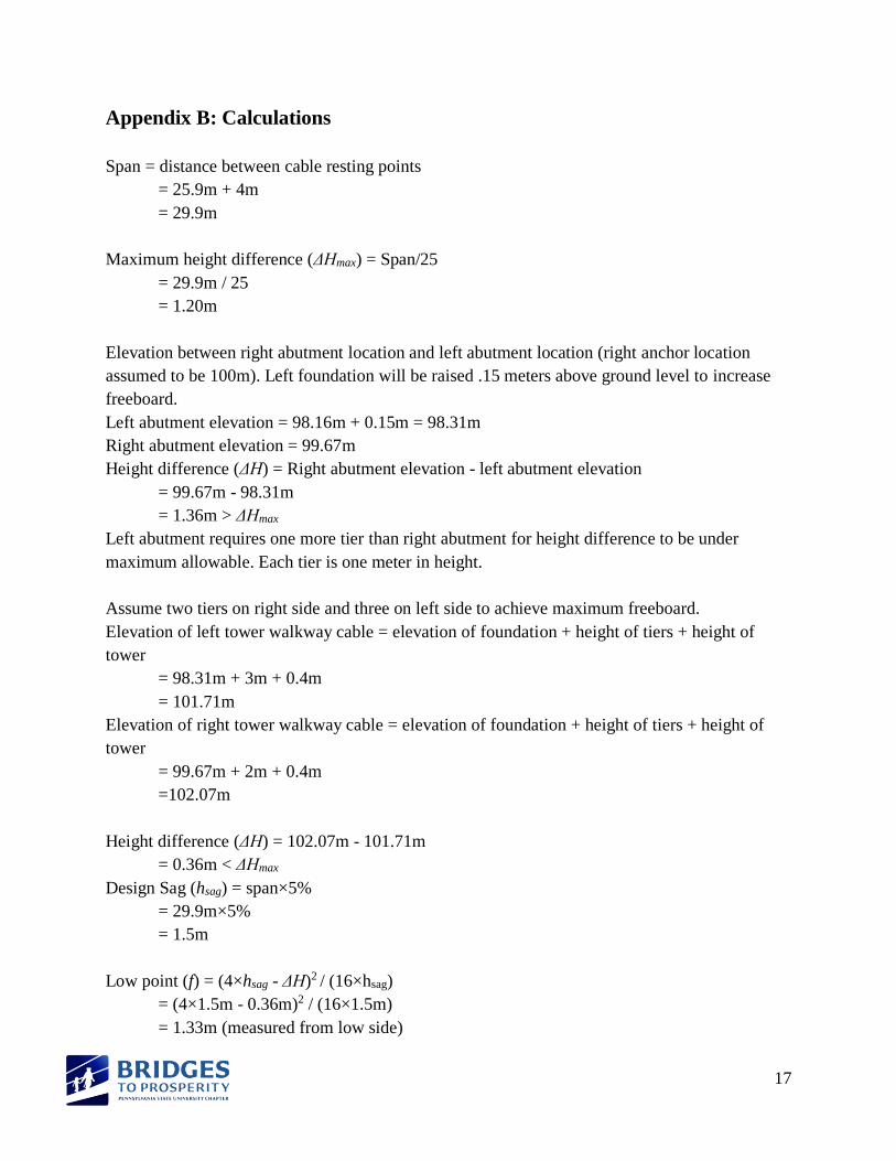
Appendix B: Calculations
Span = distance between cable resting points
= 25.9m + 4m
= 29.9m
Maximum height difference (ΔHmax) = Span/25
= 29.9m / 25
= 1.20m
Elevation between right abutment location and left abutment location (right anchor location
assumed to be 100m). Left foundation will be raised .15 meters above ground level to increase
freeboard.
Left abutment elevation = 98.16m + 0.15m = 98.31m
Right abutment elevation = 99.67m
Height difference (ΔH) = Right abutment elevation - left abutment elevation
= 99.67m - 98.31m
= 1.36m > ΔHmax
Left abutment requires one more tier than right abutment for height difference to be under
maximum allowable. Each tier is one meter in height.
Assume two tiers on right side and three on left side to achieve maximum freeboard.
Elevation of left tower walkway cable = elevation of foundation + height of tiers + height of
tower
= 98.31m + 3m + 0.4m
= 101.71m
Elevation of right tower walkway cable = elevation of foundation + height of tiers + height of
tower
= 99.67m + 2m + 0.4m
=102.07m
Height difference (ΔH) = 102.07m - 101.71m
= 0.36m < ΔHmax
Design Sag (hsag) = span×5%
= 29.9m×5%
= 1.5m
Low point (f) = (4×hsag - ΔH)2 / (16×hsag)
= (4×1.5m - 0.36m)2 / (16×1.5m)
= 1.33m (measured from low side)

18
High Water Level (HWL) = 97.52 m (from survey data)
Freeboard (Fb) = Low side elevation - f - HWL
= 101.71m - 1.33m - 97.52m
= 2.86m
Minimum Freeboard for gorges = 3m
Hoisting Sag = Span×4.6%
= 29.9×4.6%
= 1.38

Appendix C: Design Calculation Tables
Table 1: Cable Look-up Tool (Reference provided by Bridges to Properity)
DECK CABLES:
3 @ 108,000 pounds
HAND CABLES:
2 @ 108,000 pounds
TOTAL BREAKING FORCE = 540,000 pounds
MAXIMUM SPAN LENGTH FOR 540000 lb. CABLE CAPACITY (FS=3)
Deck Width: 100cm
Max Span: 89m
Sag (m): 4.45
Table 2: Design Loading
Assumed Material Unit Weights
Reference: Suspended Bridge Manual, 4th edition,
Volume 3 part 1.1
Steel 7850 kg/m3 = 76.9 kN/m3
Concrete 2400 kg/m3 = 23.5 kN/m3
Gabions 1900 kg/m3 = 18.6 kN/m3
Timber 900 kg/m3 = 8.8 kN/m3
General Soil 1800 kg/m3 = 17.6 kN/m3
Loads
DL 100 kg/m = 0.98 kN/m
LL 415 kg/m = 4.07 kN/m
WL 30 kg/m = 0.29 kN/m
Load Combinations
Application
DL+LL 515 kg/m = 5.05 kN/m Most components
DL+LL+WL 545 kg/m = 5.34 kN/m Loaded windguy design
DL+WL 130 kg/m = 1.27 kN/m Unloaded windguy design

Material Properties
Material
Strength
(MPa)
Strength
(ksi)
Concrete 10.3 1.5 Note: Strength if mixed by hand
Steel Pipe 240 35
Steel
Reinforcing 275 40
Timber 3.96 0.575
Soil 1.44 0.21
Table 3: Cable Quantities
Cable Quantities Cable Diameter 1 1/8"
Number of cables 5 dleft 10.6 m
dright 11.5 m
Length/Cable 68.6 m
Total Length 343 m
Clamps Spacing 144 mm
#/Cable 6 Total Number 60 Torque 225 foot*lbs.
Table 4: Additional checks for bridge clearance verification.
Site Input
Design Notes:
Horizontal Distance from Right Anchor
Front of Foundation on Left
Side 35.9 m
Design Manual: 4rd Edition of Suspended Bridge Manual
Front of Foundation on
Right Side 10 m
Horizontal Distance is assumed to be zero at right anchor
Vertical Elevations
Front of Foundation on Left
Side 98.16 m
Elevation assumed to be 100 m at the anchor location for the
left side Front of
Foundation on Right Side
99.67 m
High Water Level 97.52 m

Material Dimensions
Reference: Tower Height 1.4 m
Suspended Bridge Manual, 4th edition
Saddle Height 0.4 m
Volume 3.2
Tier Height 1 m
Foundation Height 1 m
Site Dimensions
Site Condition Gorge
Soil Conditions Soil
Span Length 29.90 m
OK *Note: Walkway saddle to walkway saddle span Initial Δh 1.51 m
Check for Δh < L/25 1.20 m
NG Part 1: 2.4 Number of Tiers on Left
Side 3
*Note: If NG, add tiers on either side to meet requirements
Number of Tiers on Right Side 2
Height of Left Abutment 5.4 m *Includes height of tower, tiers and foundation
Height of Right Abutment 4.4 m Elevation of Left Tower 102.71 m *0.15 meter of foundation exposed
Elevation of Right Tower 103.07 m Elevation of Left Walkway
Cable 101.71 m *0.15 meter of foundation exposed Elevation of Right Walkway
Cable 102.07 m Final Δh 0.36 m
OK Anchor Type Gravity
Bridge Clearance Verification
Low Elevation 101.71 m
Suspended Bridge Manual, 4th edition
High Water Level 97.52 m
Volume 3
Design Sag (Bd) 5
% of Span
Part 1: 2.4
Design Sag (hsag) 1.50 m
Hoisting Sag (Bh) 4.60
% of Span
Part 1: 2.4
Hoisting Sag (hsag) 1.38 m Design Sag Low Point (f) 1.32 m
Part 1: 2.4 Freeboard (fb) 2.9 m
Part 1: 2.4
Freeboard Limit 3 m
Part 1: 1.1 Freeboard Check 2.87 > 3 NG
Foundation Position Limits Minimum Distance from edge 3 m
OR Max degree slope 35 degrees

Table 5: Summary Table
Critical Dimensions
Span 29.9 m Deck Width 1.0 m Freeboard (fb) 2.9 m Design Sag (hsag) 1.50 m Hoisting Sag (hsag) 1.38 m Final Δh 0.36 m Depth to Anchor 0.7 m * Reference 2G60 drawing
Distance to back of left anchor 10.6 m
Distance to back of right anchor 11.5 m
Construction Drawings Reference: Suspended Bridge Manual, 4th edition, Volume 3 section 2.8
Right Side Anchor 2G60
Left Side Anchor 3G60 Tower T1 and TQ Decking Plan W31 Decking Section W32 Decking Detail W33

Appendix D: Site Specific Bridge Drawings
11
50
cm
10
60
cm


