susceptibility of cold-worked .zircoilul-2.9^t%. niobium ... · susceptibility of cold-worked...
TRANSCRIPT

AECL-5260
SUSCEPTIBILITY OF COLD-WORKED .ZIRCOilUl-2.9^T%.
NIOBIUM ALLOY TO DELAYED HYDROGEH CRACKING
by
C.E. COLEMAN
Chalk River Nuclear Laboratories
Chalk River, Ontario
January 1976

ATOMIC ENERGY OF CANADA LIMITED
SUSCfPTlBlL1TV O¥ CCLV-WORKEV ZIRCONIUM-2.5 U7! VIOBIUM AllOV
by
C.E. Coleman
Metallurgical Engineering BranchChalk River Nuclear Laboratories
Chalk River, Ontario
January 1976
AECL-5260

Susceptibilité de l 'a l l iage de zirconium-2.5% (poids) niobium
écroui aux fissures retardées dues 5 l'hydrogène.
par
CE. Coleman
Résumé
Des éprouvettes entaillées en alliage de zirconium-2.5%(poids) niobium écroui ont été soumises a des contraintes de tractionà 350 K et 520 K. A 350 K, au-dessus d'un seuil possible de contraintede 200 MPa, les éprouvettes subissaient une défaillance retardéeattribuée â des fissures par hydrure. La métallographie a montréque les hydrures s'accumulent dans les entailles et extrémités desfissures grandissantes. Le temps de la défaillance a semblé êtreindépendant de la teneur en hydrogène dans l'intervalle allant de7 â 100 ppm d'hydrogène. Les taux de croissance des fissures d'environ10" m/s obtenus par fractographie se trouvaient dans le même intervalleque ceux nécessaires pour fissurer les tubes de force. L'intensitédes efforts asymptotiques pour la défaillance retardée, K,u, semblait
In
être d'environ 5 MPav¥. Avec cette faible valeur pour K,H, de petitsdéfauts de surface pourraient se propager dans les tubes de forceastreints â de grandes contraintes résiduelles. Un allégement descontraintes et des méthodes modifiées de roulement réduiront lescontraintes résiduelles â tel point que seuls les défauts ayant 12%de l'épaisseur de la paroi, ou plus, grandiront. A 520 K aucunedéfaillance n'a été observée pour des temps trois fois plus grandsque les temps nécessaires pour les défaillances â 350 K. Le zirconium-2.5%(poids) niobium semble être à l'abri des fissures retardées causéespar l'hydrogène, à la température de fonctionnement des réacteurs.
L'Energie Atomique du Canada, LimitéeLaboratoires Nucléaires de Chalk River,
Chalk River, Ontario
Janvier 1976AECL-5260

ATOMIC ENERGY OF CANADA LIMITED
SUSCEPTIBILITY ^ CgLP-h|gRK£P ZIRCQMIOM-2 5 WT% KICBIUM ALLCYTO VELAVEV WVROGEN '
by
C.E. Coleman
ABSTRACT
Notched tensile specimens of cold-worked zirconium-2.5 wtar
niobium alloy have been stressed at 350 K and 520 K. At 350 K, above a
possible threshold stress of 200 MPa, specimens exhibited delayed
failure which was attributed to hydride cracking. MetallograDhy showed
that hydrides accumulated at notches and tips of growing cracks. The
time to failure appeared to be independent of hydrogen content over
the range 7 to 100 ppm hydrogen. Crack growth rates of about 10" m/s
deduced from fractography were in the same range as those necessary to
fracture pressure tubes. The asymptotic stress intensity for delayed
failure, !(,„, appeared to be about 5 MPavfn. With this low value of
K,H small surface flaws may propagate in pressure tubes which contain
large residual stresses. Stress relieving and modified rolling procedures
will reduce the residual stresses to such an extent that only flaws
12% of the wall thickness or greater will grow. At 520 K no failures
were observed at times a factor of three greater than times to failure
at 350 K. Zirconium-2.5 wt% niobium appears to be safe from delayed
hydrogen cracking at tne reactor operating temperature. '••••••
Metallurgical Engineering BranchChalk River Nuclear Laboratories
Chalk River, OntarioJanuary 1976
AECL-5260

ATOMIC ENERGY OF CANADA LIMITED
S U S a n j B J L J T V OF CCLV-li'CFMV Z l k T f . U U i l - f . S U'Tre \1CBJUU ALU
TP VI LAVfV UVVRCC-tM CRACKING
b y
C.E. Co1er.an
Pressure tubes n<?de from cold-wortcec i ircomijri-^. b w*
niobium alloy have cracked during service in Pickering-? and --. *"e
cracks started at the inside surfaces of the pressure tubes end vere
located in a region just in-bcard from the rolled joint. They appeared
to propagate either while the reactor was cold or during start-up or
shutdown rather than when the reactor was at full power. Metaliographic
observations and similarity to fractures in end cap welds in fuel
sheathing stronoly suggest that delayed hydrogen crackinq is the chief
cause of failure (1). This mechanism requires (2)
- a source of hydrogen and the presence of hydrides
- a stress gradient to concentrate the hydrogen and enhance
precipitation of hydride
- a large tensile stress to fracture the hydride.
These requirements are all present in Pickering pressure tubes since
- a hydrogen content up to 25 ppm is permitted by the
specification and a typical value is 10 ppm. At temperatures
less than 370 K much of this hydrogen will be precipitated
as hydride (3-5).

- 2 -
the tube rolling-in process protruded beyond the end fittings
causing residual tensile stresses in the pressure tubes
up to 600 MPa (87 kpsi} (6). The residual stresses
have a gradient both through the tube wall and along the
tube. The cracking coincided with the highest tensile
stress which is at the inside surface just beyond the
rolled joint.
Stress rupture tests have been done to find the limiting
conditions of stress and hydrogen concentration for this type of
cracking. The current series of tests were done at 350 K, the temperature
at which Pickering-3 was held during a long shutdown in 1972, and at
520 K, the temperature at the inlet end of a fuel channel when the
reactor is at power. Fracture mechanics is used to interpret the
cracking behaviour of the material and to give a prognosis for the pressure tubes.
2. EXPERIMEfcTAL TECHNIQUE
Test specimens were machined from the transverse direction
of the front and «f Bruce tube #929 which was cold-worked 24.55S.
Samples were flattened then stress relieved 24 h at 670 K before
machining. The normals of the hydride plates remained radial after
.flattening and stress relieving. The partial composition of the test
material was
Hb 2.7 vtt%
0 1130 ppm
H 7 ppm
The microstrueture, Figure 1, consisted of plates of ct-phase elongated
in the longitudinal and transverse directions, containing many dislocations
and surrounded by a thin layer of partially transformed B-phase. The

- 3 -
specimens had the dimensions shown in Figure 2. The gross cross-
sectional area was twice the net area at the notch, Some specimens
had 100 ppm hydrogen added at 670 K and were then homogenised at
670 K for one week.
Stress rupture tests were done in constant load creep
machines at 350 K and 520 K in air and the time to failure was measured.
The specimen displacement was observed at regular intervals by dial
gauge on the lever arm of the creep machine. Elongation was taken as
full s p e c f ^ S length" thUS ** aCtUa' •t"1n **
the notch is very much underestimated. Metallography and scanning
electron microscopy were used to examine the specimen after testing.
Stresses were calculated using the area at the notch. Fracture
mechanics was used to estimate the relationship between critical flaw size
and shape and the applied stress. The stress intensity, K p relates to
the stress distribution around a crack. Once a sharp crack is initiated
in round notched bars,
^ = Co (TTD)*5
where a = stress at root of notch
D = outside diameter of specimen
C = constant
= 0.24 for present specimens
This is a valid number for further calculation if
K < & )l & ) °ys twhere °ys = yleld s t r e s s )»the condition for plane strain. In the current specimens, values of K-j
below 20 MPavfn are valid.

- 4 -
To get reference strengths and to determine the notch sensitivity
of the material, notched and unnotched specimens were tensile tested at
295 K, 350 K and 520 K using a cross-head speed of 20 ym/s, Table 1.
The notch sensitivity ratio,
UTS of notched specimen jUTS of unnotched specimen
of between 1.5 and 1.6 shows that cold worked zirconium-2.5 vtt% niobium
is not notch sensitive.
3. RESULTS
The elongation-time curves had characteristics similar to
the electrical resistance-time curves reported for the delayed failure
of steel (7) and titanium alloys (8). Some specimens had curves which
looked like creep curves with primary, secondary and tertiary stages
leading to final fracture, Figure 3. The behaviour of most specimens
is typified in Figure 4. After initial primary creep there is a period
of no deformation. Thereafter the elongation gradually increases and
the specimen fractures. The increase in deformation rate started at
a mean time of about half the specimen lifetime with a range of 0.3 to
0.7 of the specimen lifetime.
Figure 5 shows that the time to fracture increases with
reduction in stress and stress intensity, K-j. The trend band for
95% of the tests at 350 K is concave upwards suggesting an asymptotic
approach to a threshold stress intensity, which is around 7 MPsyfii for
the lower bound line. Below the asymptotic value of K p called K|H, cracks
will not initiate or will take such a long time to initiate that they are
of no practical importance. The results of delayed failure tests on

- 5 -
TABLE 1: Strengths of Starting Material
TemperatureK
295
350
520
Unnotched UTS*MPa
840
755
585
Notched UTSMPa
1270
1200
910
Notch SensitivityRatio
1.5 (1)
1.5 (9)
1.5 {6}
* Ultimate tensile stress.

- 6 -
steels are usually plotted as the logarithm of time (7). When
this is done, Figure 6, the asymptotic effect is diminished and
suggests that K-jH is about 5 MPatfii. In the stress range of the
tests no effect of increasing the hydrogen content from 7 ppm co
100 ppm is observed.
The susceptibility to cracking is much reduced at 520 K.
Four specimens, one of which was hydrided to 100 ppm, survived to
times a factor of three greater than the upper bound line for the
tests at 350 K, with no sign of increasing deformation, Figures 5
and 6.
One specimen of as-received material, loaded to a Kj of
15.3 MPa*¥, received twelve thermal cycles at intervals of 100 h.
The cycle consisted of 2 h to heat from 350 K to 520 K, a hold
time of h h then 3 h to cool back to 350 K. The thermal cycling
appeared to have no effect on the cracking behaviour since the time
to failure was 1400 h which is within the scatter band of the isothermal
tests at 350 K.
Unnotched specimens containing as-received hydrogen contents
have not exhibited delayed failure at 350 K. A specimen stressed at
670 MPa (0.9 UTS) failed by creep rupture in 1485 h with a total

- 7 -
elongation of 102. The fracture was a "cup and cone". A second specimen
was stressed at 600 MPa (0.8 UTS) and after 3100 h had deformed very
little. The specimen was then tensile tested at room temperature.
The mechanical properties were identical to those of unstressed
specimens.
The fracture surfaces of notched specimens which fractured after
short and long times were examined in the scanning electron microscope.
Only ductile features were seen in the specimen containing 7 ppm
hydrogen which broke after 12 h. In a specimen which took over 700 h
to fracture,the outer rim (immediately under the notch) contained
flat fracture, Figure 7. Examination at high magnification revealed
feathery platelets in this region, Figure 8, which others have
associated with delayed hydrogen failure (9). The central, elliptical
region consisted of ductile dimples. Specimens containing 100 ppm
hydrogen also had an outer rim of flat fracture but the central region
contained the jagged steps corresponding to fracture associated with
hydrides parallel to the applied stress, (10) Figure 9. These features
were common to each type of specimen with a trend for the rim width to
increase with increase in time to failure and decrease in stress.
Little hydride was observed near the fracture surface of
broken specimens examined by metallography. Two specimens were examined
before they broke; one was stopped just at the start of the increasing
deformation regime (A, Figure 4) and the other when deformation was
well advanced (B, Figure 4). The hydrogen, as manifested by hydrides,
concentrates in the region of high stress in the region of the notch.
Before the crack starts large hydrides (= 30 urn long) form, perpendicular
to the stress, near, but not at, the root of the notch, Figure 10.

- 8 "
Once cracking starts small hydrides (10-15 urn long) are found at the
crack tip, A on Figure 11, but rarely along the crack itself. Hydrides
not directly in the crack path were up to 50 ym long. Sometimes
uncracked hydrides are observed where the crack changes direction, B
on Figure 11.
4. PISCUSSION
Cold-worked zirconium-2.5 wt% niobium is susceptible to
delayed failure. Evidence that delayed failure is due to hydrogen
is:
- hydride close to the notch at the crack tip
- the rim of feathery fracture below the notch
- lack of delayed failure at 520 K and with smooth-sided
specimens at 350 K
- the similarity between present elongation-time curves and
those for hydrogen embrittlemen of steel and titanium.
According to the theory of delayed failure, hydrogen migrates
to high stress regions to relieve tensile stresses both when in solid
solution and when precipitated as hydride. Hydrides form where
triaxial stresses are highest, near the notch (11) (Figure 10), when
the local terminal solubility is exceeded. The equation for the flux,
J, of hydrogen, to the stress concentration has the form (2).
where D = diffusivity of hydrogen
Cg = concentration of hydrogen
= terminal solid solubility of hydrogen
^ = stress gradient
- 9 -
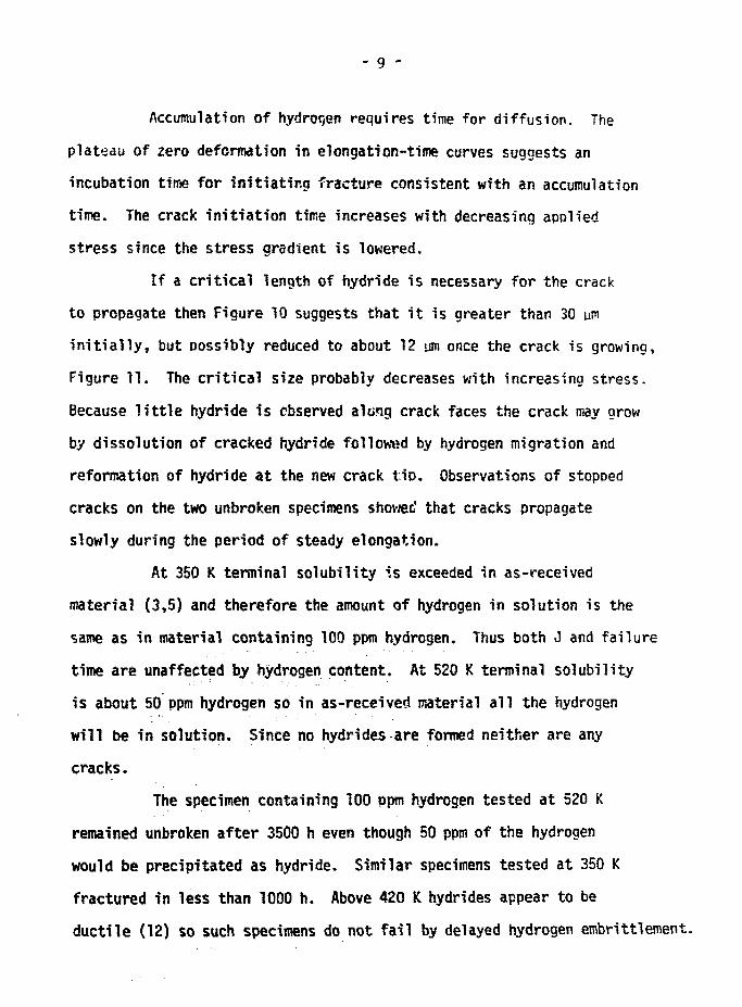
Accumulation of hydrogen requires time for diffusion. The
plateau of zero deformation in elongation-time curves suggests an
incubation time for initiating fracture consistent with an accumulation
time. The crack initiation time increases with decreasing applied
stress since the stress gradient is lowered.
If a critical length of hydride is necessary for the crack
to propagate then Figure 10 suggests that it is greater than 30 um
initially, but possibly reduced to about 12 iju once the crack is growing,
Figure 11. The critical size probably decreases with increasing stress.
Because little hydride 1s observed along crack faces the crack may grow
by dissolution of cracked hydride follow»d by hydrogen migration and
reformation of hydride at the new crack tip. Observations of stopped
cracks on the two unbroken specimens showed that cracks propagate
slowly during the period of steady elongation.
At 350 K terminal solubility is exceeded in as-received
material (3,5) and therefore the amount of hydrogen in solution is the
same as in material containing 100 ppm hydrogen. Thus both J and failure
time are unaffected by hydrogen content. At 520 K terminal solubility
is about 50 ppm hydrogen so in as-received material all the hydrogen
will be in solution. Since no hydrides are formed neither are any
cracks.
The specimen containing 100 ppm hydrogen tested at 520 K
remained unbroken after 3500 h even though 50 ppm of the hydrogen
would be precipitated as hydride. Similar specimens tested at 350 K
fractured in less than 1000 h. Above 420 K hydrides appear to be
ductile (12) so such specimens do not fail by delayed hydrogen embrittlement.

-10 -
The rim on the fracture surfaces is interpreted as delayed
hydroqen cracking. The average maximum growth rate of a crack due to
hydride cracking, y, can be estimated from the fractopraphs as- maximum rim thickness
Y = time to fracture
This estimate ignores the time to initiate the crack from the notch
but it is suitable for order-of-magnitude comparisons. Initial stress
does not affect y. It ranges from 4.0 x 10 m/s to 2.3 x 10" m/s
with a mean of 1.1 x 10" m/s.
The area of ductile fracture in Figure 7 was 0.53 the original
area of the notched region. The fracture stress, a P f ^ a°ea ' was
1300 MPa, close to 1200 MPa for the UTS in a tensile test on notched
specimens. Hydride cracking appears to proceed until the load bearing
area is reduced to the area which will not support the UTS of the
material. Ductile rupture follows.
Summarizing, the course of delayed hydrogen cracking appears
to be as follows: When a tensile stress is applied to a component
containing a stress concentration, hydrogen migrates to relieve the
hydrostatic tensile stress. Hydrides form at the notch with their
plate normals parallel to the applied stress. At some critical stage
the hydrides either crack or decohere from the matrix. At 350 K with
a stress intensity below 5 MPavff, cracks will take a long time to start.
The crack propagates at about 10"10 m/s until the reduced section fractures
by simple tensile overload.

- 11 -
5. IMPLICATIONS FOR PRESSURE TUBES
If the accumulation of hydrogen could be dispersed by
heating during the incubation period before crack initiation the
maximum safe length of shutdown couW be specified before cracks
are formed. Alternatively, if no benefit is obtained from thermal
cycling (as suggested by one test) the maximum sum of shutdown
times without cracks starting could be specified.
The average crack growth rate through the wall of a
pressure tube can be estimated as
wall thicknessY " shutdown times
Excluding the two years after construction but including the time
between hot conditio "ng and reactor start-up Y is about 2.4 x 10" m/s
for Pickering-3 and 3.8 x 10"10 m/s for Pickering-4. If the initial
period is included then y reduces to 5 x 10~ m/s and 6 x 10" m/s
respectively. Estimates from laboratory specimens are the same order
as these supporting the contention that the pressure tubes cracked by
the same mechanism as the laboratory specimens tested at low tempera-
ture.
The maximum depth of surface flaw, C C R, that can be tolerated
without crack growth can be estimated from (14)
2
where 0 = shape factor
c. = applied stress
The shape factor, 0, depends on the ratio of crack depth, C,
to crack length, L, and on o^/c. From the observation of elliptical
tide marks on fracture surfaces of failed tubes C/L is about 0.3 0 ) .

- 12 -
With applied stresses in the range 0.6 to 1.0 a Q is 1.5 for cracks
of this shape (14). (For long scratches, where C/L is close to
zero, Q is about 1.0.)
The applied stress, a., has two parts, residual stress, o^,
and hoop stress from coolant pressure, o^. Near rolled joints in
Pickering pressure tubes the residual hoop tensile stress is up to
600 MPa at the inside surface (6). This stress relaxes to about
480 MPa after 1600 h operation at 520 K (15). During much of the
long shutdown of Pickering-3 in 1972 coolant pressure was maintained
at 4.1 MPa, exerting a hoop stress of 54 MPa. Thus, here
GA = (oR + °H^ = 534 MPa
From equation (1) a surface flaw 0.035 mm (0.001 in.) deep may grow
by delayed hydrogen cracking at this stress. Since Pickering tubes
have to be free of flaws larger than 0.13 iron (0.005 in.) (16) then
this example shows that flaw growth in pressure tubes by delayed hydrogen
cracking is likely during a shutdown when high residual stresses are
present. The total applied hoop stress should be lower than 275 MPa if
such flaws are not to propagate.
Possible surface flaws include
- scratches and grooves rtiaining after fabrication,
- fatigue cracks produced during joint fabrication,
- contamination leading to stress corrosion cracking,
- cracking of surface hydride layer or hydrides which intersect
the surface after reorientation,
- oxide fingers (17),
but no definite conclusion has been reached.

- 13 -
To reduce the possibility of failure the residual stress
must be reduced. Joints made with no overextension during rolling-
in have residual stresses of 170 MPa or less (6). With no coolant
pressure a surface flaw about 0.34 nun (0.013 in.) deep would be
required to cause failure, that is, a sharp crack which is 8.4*
of the wall thickness. Stress relieving of existing overrolled
joints has reduced residual stress below 145 HPa (6) and now the
critical depth of surface flaw is 0.47 mm (0.019 in.) or 12? of
the wall thickness.
The above analysis is approximate - biaxiality and stress
gradients along and through the wall of the tube are ignored and
the notch in the experimental specimens is not a sharp, natural
crack - however, it does indicate that after lowering the residual
stresses crack propagation is only possible from large flaws which
should be easily detected during inspection.
Although cold-worked zirconium - 2.5 wt* niobium is
susceptible to delayed hydrogen cracking it can be safely used
if the residual stresses are kept low by improving the fabrication
techniques for rolled joints, by stress relieving or both. Also
the reactor operating procedures can be planned to minimize the
likelihood of delayed hydrogen cracking.
- 14 -
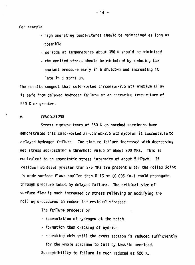
For example
- high operating temperatures should be maintained as long as
possible
- periods at temperatures about 350 K should be minimized
- the aDDlied stress should be minimized by reducing the
coolant pressure early in a shutdown and increasing it
late in a start up.
The results suagest that cold-worked zirconium-2.5 wt% niobium alloy
is safe from delayed hydrogen failure at an operating temperature of
520 K or greater.
6. CCHCLUSIOUS
Stress rupture tests at 350 K on notched specimens have
demonstrated that cold-worked zirconium-2.5 wt% niobium fs susceptible to
delayed hydrogen failure. The time to failure increased with decreasing
net stress approaching a threshold value of about 200 MPa. This is
equivalent to an asymptotic stress intensity of about 5 MPa^n. If
residual stresses greater than 275 MPa are present after the rolled joint
is made surface flaws smaller than 0.13 mm (0.005 in.) could propagate
through pressure tubes by delayed failure. The critical size of
surface flaw is much increased by stress relieving or modifying t>e
rolling procedures to reduce the residual stresses.
The failure proceeds by
- accumulation of hydrogen at the notch
- formation then cracking of hydride
- repeating this until the cross section is reduced sufficiently
for the whole specimen to fail by tensile overload.
Susceptibility to failure is much reduced at 520 K.

7. ACKhlOKLEVGUilKTS
I would like to thank J.F. Hecke and R.D. Davidson for
experimental assistance. Useful discussion with J.F.R. Ambler, t>. Cox,
C.E. Ells, W. Evans, R.R. Hosbons, £.F. Ibrahim and P.A. Ross-Ross
is much annreciated.
§.
(1) P.A. Ross-Ross, E.J. Adams, D.F. Dixon and R Hetcalfe, Proc.
European Nuclear Conference, Paris, April, 1975.
(2) C.J. Simoson and C.E. Ells, J. Nucl. Hat. 52 (1974) 289.
(3) J.J. Kearns, J, Nucl. Mat. 2£ (1967) 292.
(4) A.R. Daniel, Atomic Energy of Canada Limited Report AECL-2453 (1966).
(5) S. Hishra and M.K. Asundi, ASTM-STP-551 (1974) p. 63.
(6) P.A. Ross-Ross, J.T. Dunn, A.B. Mitchell, G.R. Towgood and 7.A. Hunter,AECL-5261, (1975).
(/) A.R. Troiano, Trans. ASN 52_ (I960) 54.
18) R.D. Daniels, R.J. Quigg and A.R. Troiano, Trans. ASM $]_ (1959)
843.
(9) I. Aitchison and J.F.R. Ambler, unpublished work at CRNL.
(10) I. Aitchison, ASTH-STP-458 (1969) p. 510.
(11) W.W. Gerberich, "Hydrogen in Metals" ASH (1974) p. 115.
(1Z) W. Evans and G.tf. Parry, J. Electrochem. Tech. 4̂ (1966) 225.
03) P.C. Paris and G.C. Sih, ASTH-STP-381 (1965) p. 30.
(14) C.F. Tiffany and J.N. Fasters, ASTW STP-381 (1965) 249.
(15) A.R. Causey, unpublished work at CRNL.
(16) AECL specification for Zr-2.5 wt? Nb cold-worked seamless tubing
for pressure tubes.
(17) C.E. Coleman, unpublished work at CRNL.

Radial direction
Longitudinal direction
FIGURE 1: f'icrostructure of starting material. Longitudinal section.

17
2.13mm DIAMETER\
25. 4M
3.05mm DIAMETER
~J 7
THREADED ENDS
RADIUS 0.025mm
FIGURE 2: nimensions of notched tens i le specimen.

1 .b
1 .4
- IP -
FRACTURE
1 .2
•
1 .0
0 .8
C.6
0.4
0.2
L100 200 300 400
TEST TIME - h
500 600 700
FIGURE 3: Elongation-time curve fo r specimen tested at 700 MPa containing7 ppm hydrogen.

1.4
1.2
1.0
* 0.8
o
•aoza 0.6
0.4
0.2 —
500 1000
FRACTURE.
1500 2000 2500
TEST TIME, h
3000 3500 4000_-iJ4500
FIGURE 4: Elongation-time curve tor snecimeo tested at 300 MPa and containina 7 oom hydrogen.

I?
c/0zUJI—z
toUJcc
25
20
15
10
T
00
35OK
NOMINAL HYDROGEN •
100 ppm HYtROGEN O
520K
A
I1000 2000 3000 4000
TIME TO FRACTURE, h
FIGURE 5: Effect of stress on tine to fa i lu re .
5000 6000
1200
1000
800
600 £
400 «
200

I?a.
25
20
15
t/i 1 nUJ ' u
1 3 1 200
35OK
NOMINAL HYDROGEN •
100 ppm HYDROGEN O
A-A-
1000
800
600
aoo
200
10 100I M E 1 0 P R A C T U R L , h
1000
rfff?ct o f s on t.inr t.n ' ,i > 1 i r f .
I o,oou

-22 -
FIGURE 7
Typical fracture surface of specimen with as-received hydrogen content. Note the rim belowthe notch.
FIGURE 8
Detail of rim region of Figure 7. Note featheryplatelets.

- 23 -
FIGURE 9
Typical fracture surface of specimen with 100hydrogen.

- 24 -
FIGURE 10
Hydrides concentrating near notch.

- 25 -
FIGURE 11
Hydrides near propagating crack.

The International Standard Serial Number
ISSN 0067-0367
has been assigned lo this series of reports.
To identify individual documents in the series
we have assigned an AECL-tsumber.
Please refer to the AECL—number when
requesting additiona! copies of this document
from
Scientific Document Distribution Office
Atomic Energy of Canada Limited
Chalk River, Ontario, Canada
KOJfJO'
Price S3.00 per copy
2595-75