sus corporation · sio2, a slim and compact karakuri controller. the new sio controller is centered...
TRANSCRIPT

1712-1,000
http://global.sus.co.jp/
The Innovator of Aluminum
SUS CorporationHead office6F, S-patio Bldg. 14-25 Minami-cho, Suruga-ku, Shizuoka-shi, Shizuoka 422-8067,JapanTEL : +81-54-202-2000 (Main) FAX : +81-54-202-2002
International salesTEL : +81-54-202-0810 FAX : +81-54-202-0807
ThailandSystem Upgrade Solution BKK Co., Ltd.Head Office, Amata Nakorn Industrial Estate 700/71 Moo 5, T. Klongtamru A. Muang, Chonburi 20000, ThailandTEL : +66-38-457069http://www.susbkk.co.th/
USASUS America, Inc.901 Cambridge Drive, Elk Grove Village, IL 60007, USATEL : +1-847-350-1525http://www.susamericainc.com/
SingaporeSUS(Singapore) Pte. Ltd.19 Tannery Road 347730, SingaporeTEL : +65-6842-4348
ChinaSUS (Suzhou) Co., Ltd.Block 25A# Industrial Workshop, Chuangtou industrial area,Suzhou Industrial Park, Suzhou 215122, ChinaTEL : +86-512-82253336
IndiaStandard Units Supply (India) Pvt. Ltd.43/1 Padasalai Street, Ayanambakkam, Chennai - 600095,Tamil Nadu, IndiaTEL & FAX : +91-44-49524482
VietnamStandard Units Supply (Vietnam) Co., Ltd.Workshop - Office X5, Hai Thanh workshop area, Hai Thanh Ward, Duong Kinh Dist., Hai Phong City, VietnamTEL : +84-313-632 403 ~ 404
PhilippinesStandard Units Supply Philippines CorporationBuilding U-2 Lot 22B Phase 1B First Philippine Industrial Park Special Economic Zone Tanauan City 4232, Batangas Province PhilippinesTEL : +63-43-430-1074 / 1076
Simple Input Output Controller
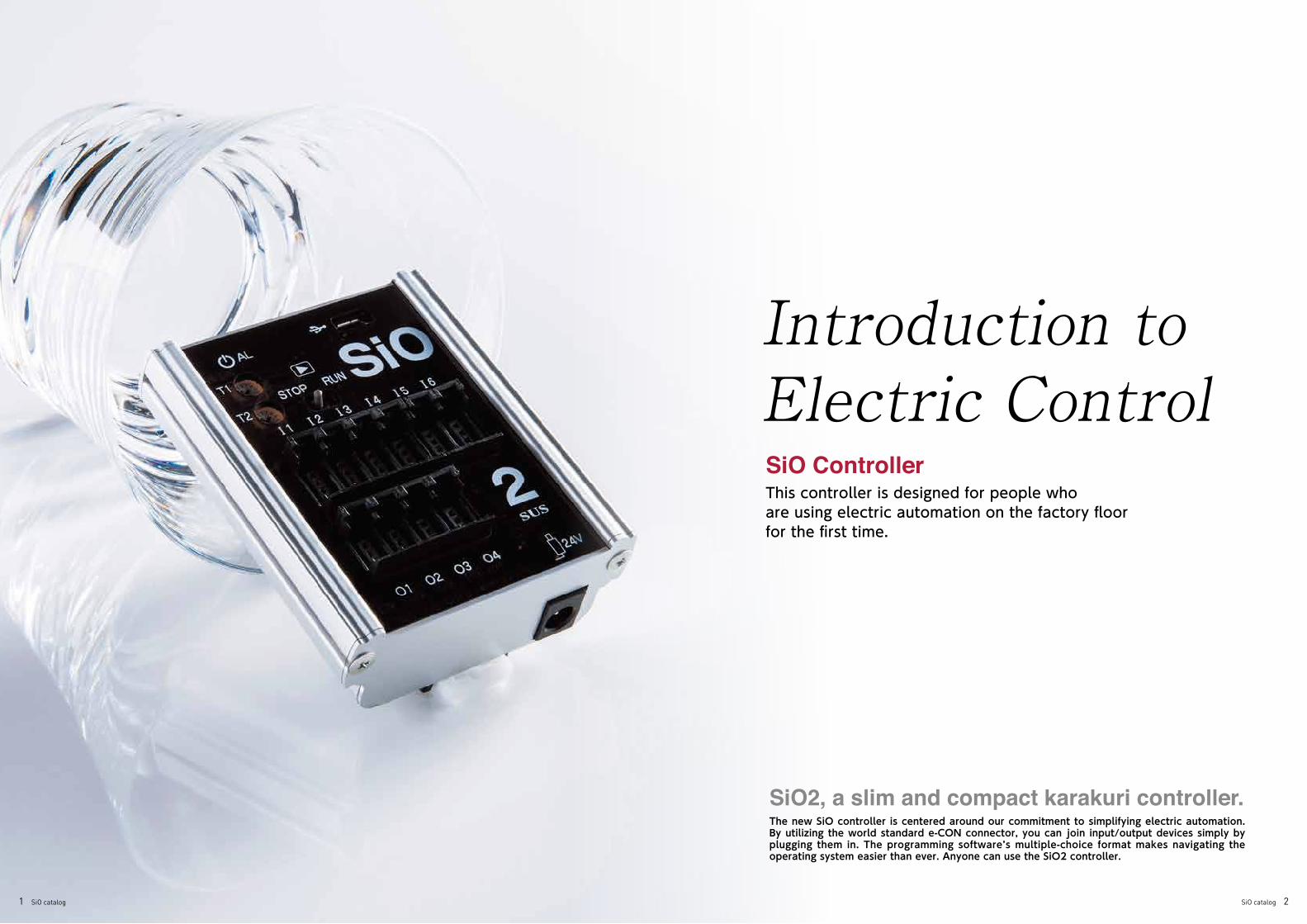
Introduction to Electric Control SiO ControllerThis controller is designed for people whoare using electric automation on the factory floorfor the first time.
SiO2, a slim and compact karakuri controller.The new SiO controller is centered around our commitment to simplifying electric automation. By utilizing the world standard e-CON connector, you can join input/output devices simply by plugging them in. The programming software’s multiple-choice format makes navigating the operating system easier than ever. Anyone can use the SiO2 controller.
1 SiO catalog SiO catalog 2

S i m p l e I n p u t O u t p u t●Introduction to Electric Control
Input Device Output Device
What is SiO (Simple Input Output) Controller?Simple and Effective
What can you do with SiO Controller?
What types of SiO Controllers are there?
Do you need in-depth knowledge of electricity or controllers to use SiO?What kind of places and situations can SiO Controller be used in?
Manufacturing lines, etc.
Inspection devices, etc.
Simple work site improvements
SiO Controller is a simple input/output control system launched by SUS in June, 2016. Here, we give an overview in the format of Question and Answer.
⃝ Sound the buzzer as long as the press button switch is being pressed.
⃝ When the photoelectric sensor reacts five times, light up the lamp.
⃝ When the limit switch detects a work piece, stop the buzzer… etc.
First, set the input conditions on SiO Controller. When the sensor detects these condi-tions, it sends a command to the output device.
When designing a system that uses electric controls in a factory setting, it used to be common to use a PLC (programmable logic controller) regardless of the task. But, by using SiO Controller, you can easily make small scale improvements that don’t require a full PLC.
While maintaining a small size of60 mm × 73 mm × 22 mm, the SiO-C is capable of connecting 8 inputs and 8 outputs. Our line-up in-cludes 3 types with differing installation mechanisms (GF con-nector/DIN rail/fastening screws). SUS also offers an e-CON connector terminal block (SUC-162) as an additional option.
This model has the minimum number of inputs and outputs.An e-CON connector terminal block is built into the main unit, so devices can be connected just by plugging them in. The housing is made from aluminum extrusion. The same protrusions as the GF Green Frame are installed on the side in addition to a DIN rail slot on the back.
Multiple-Choice Simple ProgrammingUse “SiO Programmer,” the dedicated software for Windows, to set output conditions. Even new users can easily create programs just by answering a few multiple-choice questions. SiO Programmer also has a simulator function, so you can check operations even before connecting to SiO Controller.
Just Plug In.We use the industry standard e-CON connectors※, eliminating the need for difficult wiring work. SUS also offers optional input/output devices with an e-CON connector already installed. Connecting thedevices is easy: just plug them in!
※Options are necessary for SiO-C.
Look at the ON/OFF status of an input device to send ON/OFF commands to an output device.
SUS offers two types of SiO Controllers for dif-ferent applications.
No special knowledge or experience is required. Even people making a program for the first time can use it easily.
SiO is ideal for making simple work site improvements or automating kara-kuri,especially in cases where PLC would be considered over-engineering.
These are a few of the things it can do:
Photoelectric Sensor (Reflective Type)
Buzzer
Lamp (Red)SiO Controller
PLC
SUC-162
Examples of installation on GF
SiO
Large Scale
Medium Scale
Small Scale
Press Button Switch
Limit Switch
Reducing functions to make automation user-
friendly
Highly functional, but
hard to use
More new models are in development!Keep your eyes open for future SiO Units.
8 Inputs/8 OutputsConnector : Flat Cable
6 Inputs/4 OutputsConnector: e-CON
What is SiO
?
Sound off!
Stop!
Light up!
Turn off!
Is it reacting?
Is it being pressed?
Is it detecting?
Look at the ON
/OFF status
Send ON
/OFF com
mand
When control is done with the same specs⃝ Control program +
Debug⃝ Wiring = Labor Coast
(8 hours) $480
SiO Program + Debug= Labor Cost (5 hours) $200
3 SiO catalog SiO catalog 4

● E x a m p l e sS i m p l e I n p u t O u t p u t
You want to know when a work piece has gotten stuck.
You want an alert when daily shipmentgoals are met.
You can’t have someone waiting on the inspection line at all times, so you only want to send someone when the work arrives. You need to regularly add materials to a machine,
but often forget.
A work piece is stuck!
We met today's goal!
Light
Light
Light
Inspection Process
The work is here!
Sensor
Sensor
Sensor
Sensor
[Operation Flow]1 The sensor doesn’t detect a work piece for 60 seconds.2 The light turns on.3 After ten seconds, the light turns off.
[Operation Flow]1 The sensor detects and counts work
pieces to be shipped.2 When half of the goal is reached, the “50%
Complete” light turns on.3 When the target number of work pieces
is reached, the “Goal Met” light turns on.
[Operation Flow]1 The sensor detects the work piece.2 The light turns on.3 After ten seconds, the light turns off.
[Operation Flow]1 The sensor does not detect material for ten seconds.2 The light turns on.3 After ten seconds, the light turns off.
[Necessary Parts]⃝SiO2⃝Sensor(Input)⃝Light(Output)
[Necessary Parts]⃝SiO2⃝Sensor(Input)⃝Light(Output)
[Necessary Parts]⃝SiO2⃝Sensor(Input)⃝Light(Output)
[Necessary Parts]⃝SiO2⃝Sensor(Input)⃝Light(Output)
Example
01Example
03
Example
02 Example
04
The material is running out!
IN1(Sensor)
DELAYTIME DELAY TIME ONCONTINUES60.0 10.0sec Lamp isOFF — — — — —— sec
OUTCONDITION1
CONDITION2 OUTPUT TYPEDURATION TIME(UNTIL)
1 12 2
OUTCONDITION1
CONDITION2 OUTPUT TYPEDURATION TIME(UNTIL)
1 12 2
OUTCONDITION1
CONDITION2 OUTPUT TYPEDURATION TIME(UNTIL)
1 12 2
IN1(Sensor) TIMES THEN DELAY
TIME RUN OFF ON0.050 slater 50% isON — — — — ——
IN1(Sensor) TIMES THEN DELAY
TIME RUN OFF ON0.0100 slater 100% isON — — — — ——
IN1(Sensor)
DELAYTIME DELAY TIME ONCONTINUES10.0 10.0sec Lamp isOFF — — — — ——
OUTCONDITION1
CONDITION2 OUTPUT TYPEDURATION TIME(UNTIL)
1 12 2
IN1(Sensor)
DELAYTIME DELAY TIME ONCONTINUES60.0 10.0sec Lamp isON — — — — —— sec sec
5 SiO catalog SiO catalog 6

● E x a m p l e sS i m p l e I n p u t O u t p u t
You want to know if assembly is being completedwithin the set assembly time.
You want to notify people of the work progress using lights.
I need help...
LightLightButton Switch
Work Switch
Start Switch
Stop Switch
Stop Switch
Stopped
Working
[Operation Flow]1 A worker presses the button switch when
production starts.2 The light turns on after three minutes.3 Data is recorded about whether assembly finishes in time or not.
[Operation Flow]1 Press the work switch.2 The green light turns on (red light is off).3 Press the stop switch.4 The red light turns on (green light is off).
[Necessary Parts]⃝SiO2⃝Start Button(Input), End Button (Input)⃝Light(Output)
[Necessary Parts]⃝SiO2⃝Switch(Input)⃝Stacked Lamp(Output)
[Necessary Parts]⃝SiO2⃝Switch(Input)⃝Stacked Lamp(Output)
Example
05Example
07
You want to call the factory leader. You want to know how much time has elapsed using lights.
Factory Leader
[Operation Flow]1 A worker presses the button.2 The light turns on.3 After ten seconds, the light turns off.
[Operation Flow]1 Press the start switch.2 A new lamp turns on every ten seconds.3 The lamp turns off after 50 seconds or
when the stop switch is pressed.[Necessary Parts]⃝SiO2⃝Button(Input)⃝Light(Output)
Example
06Example
0840 seconds elapsed
30 seconds elapsed
20 seconds elapsed
10 seconds elapsed
OUTCONDITION1
CONDITION2 OUTPUT TYPEDURATION TIME(UNTIL)
1 12 2
OUTCONDITION1
CONDITION2 OUTPUT TYPEDURATION TIME(UNTIL)
1 12 2
FLAG1(Measurem‥)
DELAYTIME CONDITION1 OFF ONCONTINUES180.0 sec Lamp isON — — — — ——
FLAG1 DELAYTIME CONDITION1 OFF ONCONTINUES10.0 sec Lamp1 isON — — — — ——
FLAG1 DELAYTIME CONDITION1 OFF ONCONTINUES20.0 sec Lamp2 isON — — — — ——
FLAG1 DELAYTIME CONDITION1 OFF ONCONTINUES30.0 sec Lamp3 isON — — — — ——
FLAG1 DELAYTIME CONDITION1 OFF ONCONTINUES40.0 sec Lamp4 isON — — — — ——
IN1(Start) THEN DELAY
TIMEIN2
(End) ON ON0.0 s later Measurem‥ isON — — — — ——
IN1(StartSwitch) THEN DELAY
TIME DELAY TIME ON0.0 50.0s later sec FLAG1 isON — — OR IN2(StartSwitch) ON—
OUTCONDITION1
CONDITION2 OUTPUT TYPEDURATION TIME(UNTIL)
1 12 2
OUTCONDITION1
CONDITION2 OUTPUT TYPEDURATION TIME(UNTIL)
1 12 2
IN1(Button)
DELAYTIME DELAY TIME ONTHEN 0.0 10.0s later Lamp isON — — — — —— sec
IN1(StopSw)
DELAYTIME
IN1(WorkSw) ONTHEN ON0.0 s later Stop isON — — — — —
IN1(WorkSw)
DELAYTIME
IN2(StopSw) ONTHEN ON0.0 s later Work isON — — — — ——
—
Standard Assembly Time: 3 minutes
7 SiO catalog SiO catalog 8

■ Operation Procedure
1. Remove the top container▼
2. The power unit raises the lifter▼
3. The level sensor turns ON▼
4. The power unit turns OFF▼
5. The container present sensor turns OFF▼
6. The power unit lowers the lifter
■ Connections (Wiring Places)
Level Sensor
Container Present Sensor
Power Unit(Switch Connector)Operating Mode:0
IN1
IN2
OUT1
OUT2Go Backward Order
Go Forward Order
● E x a m p l e sS i m p l e I n p u t O u t p u t
■ Device Image
■ I/O Table
■ Part Table
No. Input Part No. Output Part
Ⅰ1 Level Sensor O1 Power Unit Go Forward Order
Ⅰ2 Work Piece Present Sensor O2 Power Unit Go Backward Order
Ⅰ3 O3
Ⅰ4 O4
Ⅰ5 O5
Ⅰ6 O6
Ⅰ7 O7
Ⅰ8 O8
No. Product Name Model Quantity
1 SiO2 Basic Kit 1 SIO-K10 1
2 Power Unit XAK-P06 1
3 AC Adapter C1P-401P 1
4 Output Cable for the Power Unit SUC-191 1
5 Photoelectric Sensor (Reflective) SUC-195 2
6 Equipment Rack Set GFU28034220 1
LifterKeeping the containers at a consistant height.Raises the containers to the height of the level sensor.Take out one container and the next will be raised until it reaches the height of the level sensor.When the lifter is empty, the entire unit will lower.
■ Program Input
Container
Level Sensor
Power Unit
Container Present Sensor
OUT1:Power Unit Go Forward OrderOUT2:Power Unit Go Backward Order
IN1:Level SensorIN2:Container Present Sensor
①
⑥
⑤
②
OUTCONDITION1
CONDITION2 OUTPUT TYPEDURATION TIME(UNTIL)
1 12 2
IN1(LevelSe‥)
DELAYTIME
IN1(LevelSe‥) ONTHEN 0.0 s later Foward isON AND IN2
(Container) OR IN2(Container) OFFON ON
IN2(Container)
DELAYTIME CONDITION1 OFF ONCONTINUES1.0 sec Backward isOFF — — — — ——
9 SiO catalog SiO catalog 10
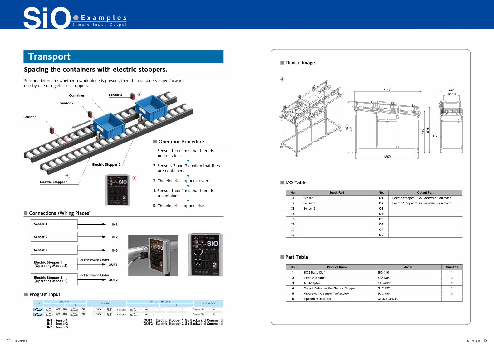
■ Operation Procedure
1. Sensor 1 confirms that there is no container
▼2. Sensors 2 and 3 confirm that there are containers
▼3. The electric stoppers lower
▼4. Sensor 1 confirms that there is a container
▼5. The electric stoppers rise
● E x a m p l e sS i m p l e I n p u t O u t p u t
■ Device Image
■ I/O Table
■ Part Table
■ Program Input
No. Input Part No. Output Part
Ⅰ1 Sensor 1 O1 Electric Stopper 1 Go Backward Command
Ⅰ2 Sensor 2 O2 Electric Stopper 2 Go Backward Command
Ⅰ3 Sensor 3 O3
Ⅰ4 O4
Ⅰ5 O5
Ⅰ6 O6
Ⅰ7 O7
Ⅰ8 O8
No. Product Name Model Quantity
1 SiO2 Basic Kit 1 SIO-K10 1
2 Electric Stopper XAK-S050 2
3 AC Adapter C1P-401P 2
4 Output Cable for the Electric Stopper SUC-197 2
5 Photoelectric Sensor (Reflective) SUC-195 3
6 Equipment Rack Set GFU28034210 1
TransportSpacing the containers with electric stoppers.Sensors determine whether a work piece is present, then the containers move forwardone by one using electric stoppers.
Sensor 1
Sensor 2
Container
Electric Stopper 1
Electric Stopper 2
Sensor 3
■ Connections (Wiring Places)
Sensor 1
Sensor 2
Sensor 3
Electric Stopper 1(Operating Mode:3)
Electric Stopper 2(Operating Mode:3)
IN1
IN2
IN3
OUT1
OUT2
Go Backward Order
Go Backward Order
OUT1:Electric Stopper 1 Go Backward CommandOUT2:Electric Stopper 2 Go Backward Command
IN1:Sensor1IN2:Sensor2IN3:Sensor3
①
⑤
②
OUTCONDITION1
CONDITION2 OUTPUT TYPEDURATION TIME(UNTIL)
1 12 2
IN1(Sensor1)
DELAYTIME
IN1(Sensor1) ONTHEN 0.0 s later Stopper1 isOFF AND IN2
(Sensor2) — — —ON ON
IN2(Sensor2)
DELAYTIME
IN2(Sensor2) ONTHEN 0.0 s later Stopper2 isOFF AND IN3
(Sensor3) — — —ON ON
⑥
11 SiO catalog SiO catalog 12

S i m p l e I n p u t O u t p u t● L i n e u p
Product Name SiO-C SiO2
Item No. XAC-035 XAC-046
Power-Supply Voltage DC24V ± 10% 0.3A DC Plug:5.5mm (outer diameter) x 2.1mm (inner diameter)
Number of Inputs/Outputs 8 Inputs / 8 Outputs 6 Inputs / 4 Outputs
Input Specifications DC24V ± 10% 7mA/DC24V Non-Voltage Contact Input (NPN) Non-Insulated
Output Specifications DC24V ± 10% 100mA/DC24V Open Collector (NPN) Non-Insulated
Communication Specifications USB 2.0 Compliant/Micro-B Type
RoHS Compatible RoHS Compatible
I/O Interface Flat Cable Connector (20 cores) e-CON Connector
External Dimensions
Weight Approximately 62g Approximately 107g
Installation Method DIN Rail GF/DIN Rail
Product Name SiO3
Item No. XAC-050
Power-Supply Voltage DC24V ± 10% 0.3A DC Plug:5.5mm (outer diameter) x 2.1mm (inner diameter)
Number of Inputs/Outputs 16 Inputs / 16 Outputs
Input Specifications DC24V ± 10% 7mA/DC24V Non-Voltage Contact Input (NPN) Non-Insulated
Output Specifications DC24V ± 10% 100mA/DC24V Open Collector (NPN) Non-Insulated
Communication Specifications USB 2.0 Compliant/Micro-B Type
RoHS Compatible RoHS Compatible
I/O Interface e-CON Connector
External Dimensions
Weight Approximately 178g
Installation Method GF/DIN Rail
8 Inputs / 8 Outputs 16 Inputs / 16 Outputs6 Inputs / 4 Outputs
DIN rail center
13 SiO catalog SiO catalog 14

S i m p l e I n p u t O u t p u t● K i t
■ SiO2 Starter Kit ■ SiO3 Starter Kit ■ SiO-C Starter Kit(e-CON)
■ SiO2 Basic Kit 1 ■ SiO3 Basic Kit 1 ■ SiO-C Basic Kit 1(e-CON)
Item No. SIO-K09
Enclosed Contents
① SiO2 main unit(XAC-046)② AC adapter(C1P-401P)③ SoftwareCD④ USB cable(SUC-121)
All necessary items including software, USB cable, and AC adapter are included for first time users. This product can be used as soon as it is delivered.
Item No. SIO-K13
Enclosed Contents
① SiO3 main unit(XAC-050)② AC adapter(C1P-401P)③ SoftwareCD④ USB cable(SUC-121)
All necessary items including software, USB cable, and AC adapter are included for first time users. This product can be used as soon as it is delivered.
Item No. SIO-K11
Enclosed Contents
① SiO main unit(DIN railtype)(XAC-035)
② Connector terminalblock (e-CON system)
(SUC-162)③ AC adapter(C1P-401P)④ I/O cable (2 side
connector 0.2 m)(SUC-117)
⑤ 24 V splitter cable(e-CON system)(SUC-207)
⑥ SoftwareCD⑦ USB cable(SUC-121)
All necessary items including software, USB cable, AC adapter, and wiring supplies are included for first time users. This product can be used as soon as it is delivered.
Item No. SIO-K10
Enclosed Contents
① SiO2 main unit(XAC-046)② AC adapter(C1P-401P)
This kit includes an AC 100 V power source (using an AC adapter).
Item No. SIO-K14
Enclosed Contents
① SiO3 main unit(XAC-050)② AC adapter(C1P-401P)
This kit includes an AC 100 V power source (using an AC adapter).
Item No. SIO-K12
Enclosed Contents
① SiO main unit(DIN railtype)(XAC-035)
② Connector terminalblock (e-CON system)
(SUC-162)③ AC adapter(C1P-401P)④ I/O cable (2 side
connector 0.2 m)(SUC-117)
⑤ 24 V splitter cable(e-CON system) (SUC-207)
This kit includes an AC 100 V power source (us ing an AC adapter) and an e -CON connector terminal block.
1 Program Editing……………………………… This function edits programs that write to SiO Controller.Edited data can be saved and printed.
2 Input/Output Monitor…………………… By connecting SiO Controller to a personal computer,you can monitor the status of the input/output devices.
3 Program Reading/Writing …………… Read the program registered in SiO Controller and writea new program to SiO Controller.
4 Simulation………………………………………… Program operation can be checked on a PC withoutconnecting to SiO Controller.
To try SiO Programmer, download the software from the SUS website and install it on your computer. You can explore program creation and simulation even before purchasing SiO Controller.
For first-time users, we also sell convenient kits with the software CD, USB cable, and AC adapter set.
What is SiO Programmer?It is multiple-choice software developed exclusively for SiO Controller.
SiO2 Starter Kit (SIO-K09)
Try using SiO programmer for free!
Main Functions of SiO Programmer
Program EditingSet the conditions to turn the output ON/OFF.
Read & Write ButtonThis communicates with SiO Controller to read and write the settings.
Other SettingsYou can set various other parameters.
Tool IconYou can compare d a t a , m o n i t o r input/output, save files, etc.
Memo InputThis is the input/output memo column. The contents are reflected in the program, input/output monitor, and simulator.
■“SiO Programmer” Operating Enviroment
Operating System Windows 7 (32Bit) / Windows8 (32Bit) / Windows8.1 (32Bit)Note: the software is not guaranteed to run on 64 Bit operating system.
CPU & Memory 800MHz and up. Usable memory 512MB.Hard Disc Free Space Free space: More than 10MBDisplay Resolution: More than 1366 X 768. Color: More than 256 colorsInterface USB port
Other You must have the Microsoft .NET Framework 2.0 installed on your PC before you can install the SiO Programmer.
15 SiO catalog SiO catalog 16

S i m p l e I n p u t O u t p u t● O p t i o n s
■ Input Device (Device → SiO) ■ Output Device (SiO → Device)
■ Output Device (SiO → Device)
■ Extension cable
■ Single Connector
■ Input Aggregate/Output Splitter
Item No. SUC-203
DescriptionThis box has a single button switch.
Cable Length:1m
Item No. SUC-196
Description
Detects when an object obscures the light between the opposing light projector and light receiver.The light projector and light receiver must be installed diagonally.
[Detected Object]Non-transparent objects.
Cable Length:2m
Item No. SUC-195
Description
This sensor detects objects by reflecting light off them.It can detect almost any object, not just metals.
[Detected Object]Objects with a certain color or shape.
Cable Length:2m
Item No. SUC-200
Description
This switch mechanically detects objects.
Cable Length:2m
Item No. SUC-201
Description
This switch mechanically detects objects.
Cable Length:2m
Item No. SUC-220
Description
This box is for an emergency stop switch. Press the switch at the B contact to turn the input OFF.
Cable Length:2m
Item No. SUC-199
Description
A red light activates with the correct input.
Cable Length:1m
Item No. SUC-206
Description
A buzzer sound activates with the correct input.
Cable Length:1m
Item No. SUC-202
Description
A solenoid valve control cable for the SMC SY series
※ Solenoid valve not included.
Item No. SUC-210
DescriptionUsed to extend cables for input.
Cable Length:2m
Item No. SUC-212
Description
Used to crimp the wiring of inputdevices.
10 piecesFor heavy lines(37104-2206-000FL) : ×7For light lines(37104-4080-G00FL) : ×3
Item No. SUC-211
Description
Used to crimp the wiring of output devices.
10 piecesFor heavy lines(37103-2206-000FL) : ×7For light lines(37103-4080-G00FL) : ×3
Item No. SUC-208
Description
Used to combine the signals of two to three input devices.
Cable Length:0.1m
Item No. SUC-230
DescriptionUsed to split signals to output devices.
Cable Length:0.1m
Item No. SUC-209
DescriptionUsed to extend cables for output.
Cable Length:2m
Item No. SUC-197
Description
This can control go forward and go backward commands.
Cable Length:2m
Item No. SUC-193
Description
This switch mechanically detects objects.
Cable Length:2m
Item No. SUC-192
Description
Detects the advancing end and the receding end.
Cable Length:2m
Item No. SUC-198
Description
Detects the advancing end and the receding end.
Cable Length:2m
Item No. SUC-191
Description
This can control go forward and go backward commands.
Cable Length:2m
Item No. SUC-194
Description
This sensor detects objects when they approach.It can detect without being affected by contamination or shape of the object.
[Detected Object]Metals including iron and aluminum.
Cable Length:2m
●Switch Box(x1)●Photoelectric Sensor (Transmission type)
●Photoelectric Sensor (Reflective)
● Solenoid Valve Cable for the SMC Products
● Extension Cable for Input (4 pins)
● Connector inputs(4 pins) ● Connector outputs(3 pins)
● Input Aggregate Cable ● Output Splitter Cable● Extension Cable for Output (3 pins)
● Output Cable for the Electric Stopper
●Rod Type Mechanical Switch (with cover) ●Rod Type Mechanical Switch
●Emergency Stop Switch Box ●Light(red) ●Buzzer
●Limit Switch ●Input Cable for the Power Unit
●With Power Unit (B) Electric Stopper Input Cable for the Electric Winch
●Power Unit With Power Unit (B) Electric Winch Output Cable for the GF
Conveyor
●Proximity Sensor
17 SiO catalog SiO catalog 18