surveying & mappingsurveying & mapping general there are many definitions of surveying. one...
TRANSCRIPT
P - 1
SURVEYING & MAPPING GENERAL There are many definitions of surveying. One of them is as follows: Surveying is the science or art of making the measurements necessary to determine the relative positions of points above, on, or beneath the surface of the earth, or to establish such points. The work of the surveyor consists largely in making such measurements and can be divided into three parts - Field Work, Computing and Mapping. Some of the more important classifications of surveying include: 1) Plane Surveying, 2) Geodetic Surveying, 3) Land Surveying, 4) Topographic Surveying, 5) Route Surveying, 6) Hydrographic Surveying, 7) Construction Surveying, and 8) Photogrammetric Surveying. Surveying is one of the oldest arts practiced by man, and is indispensable in all branches of engineering. All field operations and office computations are governed by the constant fight to eliminate or at least reduce errors. Every measurement contains an error. No measurement can ever be exact because of natural, instrumental, and personal errors, therefore, the exact answer for a measured angle or distance is never known. It is, thus, necessary to arrange computations and field work so that errors are minimized and mistakes readily uncovered. An important feature to be observed in surveying (and all engineering) is the matter of significant figures and the rounding off of numbers. The number of significant digits recorded and used in computations is important in conveying a true picture to users of the data. A distance measured with a 100-ft. steel tape graduated to tenths of a foot can be given as 236.47. It has 5 significant figures, the “7" being an estimated or interpolated number. A distance recorded as 376.2 does not mean 367.20 unless the value has been measured to hundredths, in which case the zero should have been recorded. The number of digits in a computed result depends upon the certainty of the digits in the measurements. Thus, the sum of 428.61, 25.13, and 4.2 can be carried only to 457.9. The product of 16.71 and 5.8 provides only 2 significant figures in the answer if the last digit in each factor is an estimated one. The same is true if 5.8 is divided by 16.71. Two apples means 2.00000 apples, carried to any number of decimal places. Conversely, a distance measured as 2 ft. Does not mean 2.00000 ft. unless some sort of scale which could provide that number of places was used - and again, in that case, the number should be recorded with the proper number of decimal places, not just at “2.”
P - 2
Some simple relationships between angles and distances are helpful (and necessary) in office and field work to keep errors in their proper perspective. These relationships will solve many problems in this book, and in the field, without the use of tables. Nat. sin of 1 min = nat. tan 1 min = 0.000 291 (use 0.000 3 for quick approx.) Nat. sin of 1° = nat. tan 1° = 0.017 452 (use 0.0175 or 0.01 3/4 for quick approx.) Although natural sins and tangents do not vary in straight line fashion, close approximate solutions can be obtained by assuming such a relationship over a limited span. Thus, the nat. sin of 10° is approx. = 10 x 0.01745 = 0.1745. The correct tabular value is 0.173648, hence, the error is only about 0.5 of 1% in the range from 1° to 10°. Two practical field relationships are: 1 min. of arc = 0.03 ft. At 100 ft. (approx.) 1 min. of arc = 1 inch at 340 ft. (approx.), or simpler, 1 min. = 1" at 300 ft. In triangulation work, 1 sec. of arc = 1 ft. At 40 miles (approx.) Example: What is the approximate error in the measured value of an angle if the back sight is mistakenly taken on a point 6 inches off line, the back sight being 800 ft.?
1 inch = 1 min. at 300 ft. = 3/8 min. at 800 ft. Then 6 inches = 6 x 3/8 min. = 2 1/4 min. or approximately 2+ minutes.
(1) Plane Surveys:
(a) are made to locate precisely the points for horizontal control. (b) cover limited areas and disregard the earth’s curvature. (c) are conducted by means of a plane table. (d) are used to locate ground points for aerial photography.
(2) Geodetic Surveys:
(a) are conducted from an aeroplane for the purpose of mapping. (b) involve large areas and take the earth’s curvature into account. (c) are made with the surveyor’s compass. (d) are a type of hydrographic survey.
(3) Topographic Surveys are surveys for:
(a) determining land boundaries and areas. (b) determining the shape of the bottom of rivers, lakes and harbors. (c) locating objects below the earth’s surface. (d) determining the shape of the surface of the ground and the location of natural
and artificial features on it.
P - 3
(4) A term used to describe an apparent movement of the cross-hairs over the image, due to a slight movement of the eye from side to side is called: (a) astigmatism. (b) myopia. (c) parallax. (d) refraction.
(5) The condition of parallax occurs in a transit or level telescope because:
(a) the eyepiece is focused for infinite distance. (b) the intersection of the cross-hairs is not on the longitudinal axis of the telescope. (c) the cross-hairs and the image from the objective lens are in the same plane. (d) the cross-hairs are not in the focal plane of the eyepiece.
(6) In order to avoid repeating an error of the original computer, calculations should be
checked by: (a) repeating the operations of the original computer. (b) computing by a different method than the original computer. (c) checking the original data. (d) reviewing the transcription of data and checking the calculation by independent
methods. (7) An auxillary scale which slides along the main scale of a transit permitting the smallest
divisions of the main scale to be subdivided is called a: (a) micrometer (b) planimeter (c) Vernier (d) declinator
(8) The least count of a vernier is the:
(a) number of divisions on main scale divided by number of divisions on vernier. (b) difference in number of divisions on main scale and vernier. (c) value of smallest division on main scale divided by number of divisions on
vernia. (d) smallest value that can be read directly from the scale.
(9) A supervisor’s relations with his subordinate chief of party should be:
(a) standardized and uniform for each case in order to be fair. (b) varied depending upon circumstances (d) serious and determined in each case. (c) controlled with no show of emotion (e) personal in each case.
(10) The most important job of a supervisor of field survey parties is to:
(a) make himself liked. (b) get work done efficiently. (d) impress his men with his ability. (c) enforce discipline (e) build a reputation for fairness.

P - 4

P - 5
(11) Before making a survey between certain points for a possibly highway location, the first step is to obtain: (a) any state road maps covering the general area. (b) a quadrangle map of the USGS and any serial photos and check them. (c) locations of any benchmarks in the area. (d) locations of any statewide coordinate points.
(12) In highway surveys, to determine drainage requirements, if quadrangles and air photos
are not available: (a) the perimeter of larger drainage areas may be traversed. (b) small areas visible from centerline can be fanned from points on it. (c) high water marks are sometimes accepted based upon physical evidence only. (d) all of the above correct (e) none of the above correct
P - 6
LINEAR MEASUREMENTS:
Linear measurements are required in every phase of surveying and engineering - in fact, in every branch of human behavior. Surveying measurements have been made with poles, rods, Gunter’s chains, Engineer’s chains, braced wooden panels, steel wires, steel tapes, etc. Measurements of long lines are now being made with various electronic devices - the geodimeter (using the speed of light), and the tellurometer (using the speed of a high frequency radio wave).
Lengths associated with the various measuring instruments are as follows: 1 pole = 1 rod = 1 perch = 16 ½ ft. 1 Gunter’s chain = 66 ft. = 100 links = 4 rods 1 meter = 39.37 inches = 3.2808 ft. 1 Engineer’s chain = 100 ft. = 100 links 1 vara = 33" in Cal. = 33 1/3 in Texas 1 mile = 5,280 ft. = 80 Gunter’s chains
Nine sources of errors are present in taping: 1) Incorrect tape length, 2) Temperature, 3) Tension, 4) Sag, 5) Alignment, 6) Tape not level, 7) Plumbing, 8) Marking, 9) Reading or Interpolation. Formulas for computing corrections arising from these sources are listed for convenient use. Incorrect length T = RC T = true length, R = recorded length, C = tape constant Temperature Ct = 0.000 0065 (Tt-T)R Tape standard temperature, usually 68°F in U.S.
Tt - temperature of tape during measurement, R = recorded length of line Tension (Pull) Cp = (P1-P)L/AE P1 = tension applied in lbs., P - standardization pull in lbs., A = cross sectional area of tape in sq. Ins., E = modulus of elasticity of steel in lbs. per sq. in. (usually taken as 29,000,000 #/sq.in.) Normal Tension Pt = 0.2W (AE)/(Pt-P) W = total weight of tape in lbs, Pt = total pull on tape in lbs, P, A, and E as above. Sag Cs = L - d = W2L/24P2 = w2L3/24P2 w = weight of tape in lbs per ft, L = length in ft of curved tape between supports, d = chord distance in ft. between supports. Alignment Ca = d2/2L d = distance one end of tape is off line. Slope Cs = h2/2L h = difference in elevation between two ends of tape.
Useful approximate relationships are as follows: 1) A 0.01 ft change in length of the standard 100-ft steel surveyor’s tape is produced by 1) 15°F change in temperature, 2) 15 lbs. Difference in pull based on the typical cross section, 3) 7 3/8 inches sag at the center, 4) 8 ½ inches off line at midpoint, 5) one end 1.4 ft. too high or 1.4 ft. off line.
All taping errors produce the same result in effect - they make the tape too long or too short - and consequently, all taping problems can be reduced to 4 basic situations: 1) Measuring a distance with a tape that is too short, 2) Measuring a distance with a tape that is too long, 3) Laying out a distance with a tape that is too short, 4) Laying out a distance with a tape that is too long. “Measuring” a distance means determining the length between fixed points, whereas “Laying Out” a distance means setting one point at a particular distance from a fixed point.

P - 7
It is easy to become confused in mentally making corrections for any of the four conditions but a simple sketch as shown in Example 1 will always clarify the problem.
Example 1: A distance of 278.31 ft. is to be laid out with a tape that is 99.88 ft. long between end graduations because of manufacture, temperature, tension, sag, etc. - any of the various types of error. What distance must be used?
In the sketch, the fixed point A, and the point to be established, B, are shown. True 100-ft. lengths are indicated by the long dashes, actual tape lengths by the short lines (the difference in the true and tape lengths being exaggerated as it always should be for clarity in illustrating problems). It is obvious that because the tape is too short and the third length laid out will not reach the point it should, hence a distance longer than 78.31 ft. must be used with this tape. The distance to be marked with the tape is 278.31 x 100/99.88 = 278.64 ft. Or more simply, 278.31 + 2.78 (100.00 - 99.88) = 278.31 + 2.78 (0.12) = 278.64 ft.
Example 2: A standardized steel tape 100.13 ft. long at 68°F is used to measure a line when the temperature is 14°F. The recorded length is 874.32 ft. What is the true length?
Tape length correction = 8.7432 x 0.13 ft. = +1.137 Temperature correction = 874.32 x 0.0000065 x 54° = - 0.307
Total correction = + 0.830 Recorded length = 874.32 True length = 875.15 ft.
Comparison of the precision of measurements made of the same or different lines is made by
means of the “ratio of error.” Ratio of error is computed by taking the difference in two measurements of the same line and dividing it by the average of the lengths, the answer being given as a ratio.
Example 3: The length of a series of connected lines (a traverse) is found to be 1,247.62 ft. in the forward direction, and 1,247.85 ft. in the reverse direction. What is the ratio of error? The ratio of error is (1,247.85 - 1,247.62)/1,247.74 = 0.23/1,247.74 = 1/5,400. Note that there are only two significant figures in 0.23, and therefore, there can be only 2 in the answer. Since the two measurements did not agree within 0.23 ft., a slight difference making the value 0.22 or 0.24 would change the ratio of error to 1/5,700 or 1/5,200, much too large a variation to worry about more than two significant figures in what is intended to be only a comparative value.
Example 4: A base line was measured using a 100 ft. steel tape with standardization data as follows: interval 0 mark to 100 ft. mark, 15 lb. tension, supported throughout, 100.008 ft.; interval 0 mark to 100 ft. mark, 15 lb. tension, supported at ends only, 99.963 ft. Measured average distance (9 sections) = 870.564 ft. Average temperature - 59.3°F.
The four corrections are: a) Inclination: total using formula Cg = h2/2L for each tape length = -0.140 ft.

P - 8
b) Temperature: Ct = (59.3 - 68) (0.0000065)(870.24) = -0.049 c) Standard length for full tape lengths: CL = 8(-99.963 + 100.000) = -0.296 d) Standard length & sag for partial tape length:
length portion 0.008(70.216)/100.000 = +0.006 = +0.006 sag effect for full tape length = 99.9633 - 100.008 = -0.045
for partial length = (70/100)3 (-0.045) = -0.015 Total Correction -0.494 ft.
True length = 870.564 - 0.494 = 870.070 ft.
Example 4.1: A slope measurement of 29.954 m was made between two points which has a slope angle of 4°30'. Determine the horizontal distance.
SOLUTION Using Ex. (4.1) yields H = (29.954)(Cos 4°30')=(29.954)(0.996917) = 29.862 m
Example 4.2: It is desired to set point D a horizontal distance of 195.00 ft. from point E along a line which has a slope angle of 5°30'. What slope distance should be measured in the field?
SOLUTION Using Eq. (4.1), we obtain S = H = 195.00 = 195.90 ft. Cos_ 0.995396
Reduction of slope to horizontal distances can also be determined by using the difference in elevation between the two ends of the line. Referring to Fig. 4.9 yeilds
H2 - s2 - h2 from which
S = (H2+h2) ½ (4.2) and H = (s2-h2)1/2 (4.3) which are the direct relations for the slope and horizontal distances, respectively.
Expanding the right side of Eq. (4.3) with the binomial theorem yields H = s + ( - h2 - h4 - ...)
2s 8s3 (4.4)

P - 9
Traditionally, the quantity enclosed by parentheses in Eq. (4.4) is designated the slope correction, labeled Ch in Fig. 4.9. The same equation can be used to calculate the slope distance necessary to lay out a given horizontal distance.
For moderate slopes, the first term within the parentheses of Eq. (4.4), h2/2s, is usually adequate. The error introduced by Eq. (4.4) using only the first term is negligible for ordinary slopes. The degree of approximation is shown in Table 4.2.
Thus, for slopes not exceeding 15 percent, the second term is not significant unless relative precisions of 1:15,000 or better are required. Fig. 4.9 Slope Correction Example 4.3: A distance of 130.508 m was measured over terrain with a constant slope along a sloping line which has a difference in elevation between the two ends of 5.56 m. Calculate the horizontal distance between the two points. SOLUTION By Eq. (4.3), H = [(130.508) 2 - (5.56) 2] ½ = 130.390 m Table 4.2 _________________________________________________________
Error caused by using Eq. (4.4) Difference in elevation per with only one term in 100 ft. 30 m 100 ft. 30 m
of slope distance of slope distance _______________________________________________________ ft m ft m _______________________________________________________ 5 1.5 0.0001 0.00002 10 3 0.001 0.0004 15 4 0.006 0.0012 20 6 0.02 0.006 30 9 0.1 0.03 40 12 0.3 0.1 60 18 1.6 0.5 _____________________________________________________

P - 10
Example 4.4: Point R is to be set at a horizontal distance of 98.25 ft. from point Q along a sloping line where the difference in elevation between R and Q is 4.35 ft. Calculate the slope distance to be measured in the field. SOLUTION Using Eq. (4.2) yields s = [98.25) 2 + (4.35) 2]1/2 = 98.35 ft. Example 4.5: A distance was measured over irregularly sloping terrain. Slope distances and differences in elevation are tabulated in the two columns on the left of the following table. Calculate the horizontal distance. _____________________________________________________ Slope Difference in Horizontal distance_____ elevation,____ distance,_____Ch = h2 / 2s,_ ft. ft. ft. ft. _____________________________________________________ 100.00 3.50 99.94 0.06 100.00 5.30 99.86 0.14 80.50 4.20 80.39 0.11 100.00 8.05 99.68 0.32 62.35 5.25 62.13 0.22 442.85 442.00 0.85 - 0.85 442.00 ____________________________________________________ SOLUTION: H is calculated using Eq. (4.3), individually for each length and tabulated in the third column. The total horizontal distance is the sum of the calculated H’s. An alternative is to compute the correction Ch from Eq. (4.4) using only one term, since the slopes are less than 15 percent. These corrections are tabulated in the fourth column. In this procedure, the pocket calculator or the slide rule may be used. The horizontal distance is then computed by either subtracting the sum of the corrections, Ch, from the total distance; or applying individual corrections to corresponding slope distances and taking the sum of the horizontal distances. Precision required for 0 and h: The relative precision of a measured line is usually expressed as the ratio of the allowable discrepancy to the distance measured. Thus, a relative precision of 1 in 10,000 implies a discrepancy of 1 unit in 10,000 or 0.01 unit in 100 units. Required relative precisions in measured distances for various classes of work are given in Chaps. 8 and 10. Ordinary taping is generally said to have a relative precision of 1 part in 1000 to 1 part in 5000.

P - 11
1) The Gunter’s or Surveyor’s chain is: (a) extensively used for accurate measurement of distances. (b) the unit of measure for Surveys of the Public Lands. (c) a continuous flat steel ribbon 100 ft. long. (d) preferred for use in flag open country.
2) When measuring with the steel tape over rough or sloping ground by holding the tape
horizontally, the greatest error results from: (a) holding the tape out of level. (c) too great tension. (b) careless plumbing (d) too much sag.
3) When measuring with the steel tape, the head chainman should have:
(a) the zero end ahead. (b) the 100 ft. end ahead. (c) the end ahead which is best adapted to the procedure. (d) no preference as to which end is ahead.
4) When measuring with the steel tape, it is important at the very beginning of the survey
for the chainmen to: (a) put the zero end ahead. (b) put the 100 ft. end ahead. (c) note the exact location of the zero and 100 ft. marks. (d) note the method of marking the 5 ft. intervals.
5) The usual manner of supporting a steel tape when using it under general conditions is:
(a) at both ends. (c) at ends and center. (b) at ends and quarter points (d) throughout its length on a level surface.
6) A “station” as used in measuring linear distances is considered to be any point on a
line: (a) occupied by an instrument. (b) at a multiple of a full tape length established by continuous chaining from a point
of beginning. (c) where a rod reading is to be taken. (d) established by continuous chaining from a point of beginning.

P - 12
7) The most serious errors in ordinary taping are caused by: (a) holding one end of the tape too high or too low and not making the slope
correction. (b) temperature variation. (c) errors in alignment. (d) errors in plumbing. (e) supporting the tape at ends only when standardized for support throughout.
8) A chaining party measures a distance AB along a slope with a 100 ft. tape which is
known to be too long by 0.04 ft. The distance from A at the base of the slope to B at the summit is recorded as 416.85 ft. Levels run from A to B establish a difference in elevation of 24.50 ft. The true computed distance from A to B is: (a) 416.30 ft. (b) 416.13 ft. (c) 415.96 ft. (d) none of these
9) A line measured on a 4°° 30' slope was found to be 700.25 ft. long. The horizontal distance is:
(a) 702.37' (b) 701.37' (c)700.00' (d) 698.09 (e) 689.37' 10) It is desired to lay out a line 400.00 ft. long. The ground slopes uniformly 3 feet in
100. The slope distance to be laid out is: (a) 402.61' (b) 400.18' (c)400.00' (d) 396.72' (e) 396.27'
11) A 100 ft. tape is 1.00 ft. too long. A line measured with that tape is found to be exactly
seven tape lengths. Corrected distance is: (a) 693.00' (b) 699.00' (c)700.70' (d) 707.00' (e) 714.07'
12) A hundred-foot tape is 100.00 ft. long at 15 lbs. tension; at 25 lbs. tension it is used
to measure the length of a line. Measured length = 500.00 ft. Tape is 0.020 in. X 0.20 in. in cross-section. E = 25,000,000 p.s.i. Length corrected for tension is: (a) 499.90' (b) 500.04' (c)499.95' (d) 499.96' (e) 500.05'
13) Measurement of distances by means of the Geodimeter involves use of the principle
based upon a: (a) microwave impulse (c) modulated light-wave impulse (b) radiation impulse (d) direct reckoning mechanism

P - 13
LEVELING:
Leveling is an important part of surveying and provides data and control for maps, construction, layout and operation of manufacturing processes and equipment, etc. Fundamentally it consists in measuring the vertical distance from a point of known elevation (or assumed elevation) - a bench mark, B.M., or a turning point, T.P. - to the line of sight of an instrument to get the height of instruction (H.I.), then measuring the vertical distance from the H.I. to another point to obtain a new elevation (a T.P., B.M. or perhaps an intermediate sight, I.S.). This process is repeated as many times as may be necessary, in fact all leveling is expressed by the two equations.
Elevation + Back Sight (B.S.) = H.I. H.I. - Fore Sight (F.S.) = Elevation Note that the back sight, also called the plus sight, is usually a plus value, but it can be minus, as in the case of a rod held against the ceiling of a room, or the roof of a tunnel, so that it is on a point above the H.I. Likewise, the foresight, although normally a minus value, can be plus under certain conditions.
The elevation of a point means the vertical distance above a datum. The most commonly used datum is Mean Sea Level, the average elevation of the ocean for all stages of the tides. The U.S.C. & G.S. has established almost 500,000 B.M.s for reference throughout the United States, and descriptions and elevations of them are made available free. Changes in the adjusted elevations of the benchmarks have been made several times, the last and final one for most marks having been completed in 1929. Thus, an elevation can be given as 1427.638 ft. mean sea level datum, 1929 adjustment.
Among the various types of leveling are differential (ordinary, precise, and three-wire), reciprocal, profile, barometric, trigonometric, and borrow-pit or cross-section leveling. Levels are classified as hand levels, farm levels, engineers’ levels, semi-precise levels, precise levels, and self-leveling levels.
The spacing of graduations on level vials is either 0.01 ft., 0.1 inch, or 2 mm. The sensitivity of a level vial is determined by the radius of curvature provided in the grinding of the tube, the larger the radius, the more sensitive the bubble (a drop of water runs more freely on a flat table than in a saucer). In a properly designed instrument, the sensitivity of the level vial is correlated with the magnification of the telescope so that a slight movement of the bubble is accompanied by a slight change in the apparent position of the cross-hair on a rod held perhaps 150 to 200 ft. away.
Example 1. A reading of 5.876 ft. is obtained on a rod held 300 ft. away, the bubble being centered. The bubble is then moved exactly 5 divisions by means of the leveling screws and a new reading of 6.198 is made. What is the average angular value (sensitivity) of a 0.01 ft. division on the level vial? What is the radius of curvature of the vial?
The arc for 1 division at 300 ft. = (6.198 - 5.876)/5 = 0.322/5 = 0.0644 ft. Sensitivity, sin s = 0.0644/300 = 0.000215
s = (0.000215/0.00029) x 60 sec. = 45 sec. Radius = 0.01 ft./0.000215 = 46 ft. approx.
P - 14
Some practical suggestions on leveling: 1 Check bubble centering immediately before and after taking an important reading.
2 Read rod quickly, do not continue to stare at it and change your mind.
3 In profile leveling, do not use a station as a T.P. - it tends to confuse the notes.
4 Be certain the tripod is in as good condition as the head of the instrument.
5 In hilly terrain, avoid wasting time leveling and then missing the rod by first using a hand level, or
by first sighting the rod with the bubble in the rear of the tube for uphill sights, and in the front of
the tube on downhill sights, as a safety factor.
6 Keep the line of sight as high above the ground as possible, do not wave the rod.

P - 15
1. A level surface which is used as a reference for measuring vertical distances is called a: (a) bench mark (b) grade surface (c)datum plane (d) horizontal surface
2. The term “back sight” in leveling means:
(a) a sight in the general direction to the rear. (b) the vertical distance from the line of sight to a point whose elevation is to be determined. (c) a rod reading on a point whose elevation is known. (d) a rod reading on a turning point.
3. The height of instrument as used in leveling means the:
(a) distance from the ground to the line of sight. (b) elevation of the line of sight above the datum plane. (c) height of the line of sight above the turning point or bench mark. (d) overall height of the tripod and level combined.
4. Reciprocal leveling is used when:
(a) it is necessary to correct for curvature and refraction. (b) a line of levels is run in one direction only and a check on accuracy cannot be made by
rerunning in the opposite direction. (c) the distance between two points exceeds the maximum length of sight and the
instrument cannot be set up between the points to keep the back sights and foresights balanced.
(d) the elevations of the ground surface along a definite line are desired. 5. The dumpy level differs from the wye level chiefly because it:
(a) is more accurate. (b) has the telescope removable from its supports. (c) can be adjusted more readily. (d) has the telescope rigidly attached to its supports.
6. A double rodded line of levels means a line run:
(a) in only one direction using two rods. (b) twice in the same direction using two rods. (c) using two turning points for each set up of the instrument. (d) in both directions using only one rod.
7. A Philadelphia leveling rod is a:
(a) target rod. (c) target and self reading rod. (b) self reading rod. (d) single section rod.
P - 16
8. A double rodded line of levels is a line which is run: (a) from one bench mark to another and back using a single rod and rod man. (b) from one bench mark to another in one direction only using two rod men and
rods, as in precise work. (c) from one bench mark to another either in one direction or in both directions. (d) as an especially long line which does not close on a previously established B.M. where
the elevation is known. 9. In leveling operations, the practice of keeping distances to the back sights and the
foresights equalized eliminates the error caused by the: (a) bubble tube not being perpendicular to the vertical axis. (b) axis of the bubble tube and the line of sight not being in the same vertical plane. (c) horizontal cross-hair not being truly horizontal. (d) line of sight not being parallel to the bubble tube axis.
10. The most important characteristic of contour lines on a map is that:
(a) they never cross each other. (b) they always close on each other within the limits of the map. (c) all points on any one contour are in the same direction. (d) they are not equally spaced on uniform slopes.
11. On a contour map, closely spaced contour lines indicate:
(a) flat slope. (c)A relatively sharp slope. (b) very irregular land. (d)a change in slope.
12. The grid or cross-section method of locating contours in the field is especially well
adapted to: (a) small areas, contour intervals 1-2 ft., accurate location important. (b) small areas, such as city lots, accurate location of contours not important. (c) large areas, large contour interval, map small scale. (d) large areas, large contour interval, irregular ground.
13. The interpolation method of locating contours in the field is preferable when the:
(a) ground surface is gently sloping. (c)area is small. (b) scale of the map is large (d)contour interval is large, ground is
irregular. 14. Elimination of the errors due to curvature and refraction in leveling operations is
accomplished by keeping: (a) lengths of sights less than 300 ft. (b) distances to back sights and foresights balanced.
P - 17
(c) level bubble accurately centered without regard to distances. (d) axis of line of sight perpendicular to the vertical axis.
15. A point observed by a level or transit appears to be higher than it really is because of:
(a) curvature of the earth’s surface. (b) parallax of the telescope. (c) refraction of the air. (d) convergence of light rays within the telescope.
16. The most accurate of the following methods of leveling is:
(a) reciprocal. (b) profile. (c)barometric. (d) differential. 17. A vertical section of the line of a survey showing elevations is a:
(a) plan. (b) cross-section. (c) profile. (d) detail. 18. A sewer invert at sta. 38+00 has an elevation 386.27. The gradient or rate of grade to
sta. 46+00 is -1.00%. The elevation at 46+00 is: (a) 386.19 (b) 378.27 (c) 306.27 (d) none of these.
19. In leveling, which of the following errors is more serious over several set-ups?
(a) personal errors (c) instrumental defects (b) errors due to natural sources (d) settling of the level or rod
20. In ordinary differential leveling, the elevation of any ground point is found by:
(a) adding the B.S. to the elevation of the previous point. (b) subtracting the F.S. from the elevation of the previous point. (c) adding the F.S. to the H.I. (d) adding the B.S. to the H.I. (e) subtracting the F.S. from the H.I.
21. If the bubble leaves the vial center a slight amount between the B.S. and F.S., the:
(a) foresight should be taken without releveling. (b) back sight reading should be repeated. (c) level tube must be adjusted before work proceeds. (d) level must be moved to another spot for the set-up. (e) bubble should be centered before taking the F.S. reading.
22. A line of levels of 4 set-ups is run between 2 points using a 13-ft. level rod. The rod
used has 0.1 ft. sawed off the bottom. Observed differences in elevation is 38.92 ft. Correct difference in elevation is (in ft.): (a) 38.12 (b) 38.52 (c) 38.92 (d) 39.32 (e) answer not given
P - 18
23. Contour lines which cross each other indicate: (a) an absolutely flat plane (d) an overhanging cliff (b) a peak (e) the bottom of an enclosed valley (c) a vertical cliff
24. In differential leveling, a sight on a point of known elevation is called a back sight
(B.S.). In all types of surveys, land, tunnel, surveying, etc., a B.S.: (a) is always a plus value (c) could be a minus value (b) is always a minus value (d) none of answers given
25. In leveling, if the rod is not held vertical, the reading is:
(a) usually too small (c) equally too large or small (b) usually too large (d) always too small (e) always too large

P - 19
D-TRANSIT, STADIA:
The primary angle-measuring instrument for ordinary work has been the one-minute engineers’ transit, with the 30-second and 20-second instruments quite common. Some 15-second and 10-second transits have been employed, mainly for triangulation, along with theodolites reading to 5-seconds. European theodolites reading to 1 second, or 0.1 second, and interpolated to 0.1 second and 0.01 second respectively, are in use in the U. S. today. Since 1 second = 1 foot at 40 miles, the required precision of construction of equipment to theoretically measure the angle between two points 0.01 ft. apart and 40 miles away, is evident. Accurate set-up over the stadium and perfect leveling are obviously necessary to preserve the rated reading accuracy.
Assuming that a transit is properly leveled, set exactly over the station occupied, and in proper adjustment, only two sources of error are present in measuring an angle-pointing and reading. Tests show that an experiences observer can point a 1-minute transit with an accuracy of about 5 seconds. The reading from a 1-minute instrument should be correct within 30 seconds, i.e., if the actual position of the index mark is between, say, 18'31" and 19'29", theoretically a value of 19 minutes would be read. The maximum number of repetitions of an angle feasible to correlate pointing and reading accuracy of a 1-minute transit is, therefore, approximately 30"/5" = 6.
Comparable precision of angle and stadia distance readings is given in Example 1 below. Frequently, for record and computation purposes, angles and/or distances are measured more precisely than they can be mapped, thus each case must be analyzed individually.
Example 1: How close should transit angles be read if stadia distances of approximately 300 ft. are read to the nearest foot?
Distances to the nearest foot mean they are within +/- 0.5 ft. The permissible lateral error as defined by the angles is, therefore, also +/- 0.5 ft. for consistency in plotting points or computing.
1 min. = 0.03 ft. @ 100 ft. = 0.09 ft. @ 300 ft. (approx.) Read angles to 0.5/0.09 = 5 or 6 min. (5 min.by estimation
of the index mark w/o using the vernier for American Insts.)
A vernier is an auxiliary scale used to measure a fractional part of the smallest division on the main scale without interpolation. A vernier has “n” divisions in a space equivalent to (n-1) spaces on the main scale. The “least count” of a vernier is the smallest direct reading obtainable with it.
least count 1. C. = value of the smallest division on the main scale number of divisions on the vernier
Transit scales are normally divided into 30, 20, 15, or 10-minute spaces. Verniers usually have 30, 40, 45, or 60 divisions. Direct (single), double, and folded verniers are used, the double vernier having two sides of which only one is used at a time, and the number of divisions in the formula is that for the individual side being employed.
P - 20
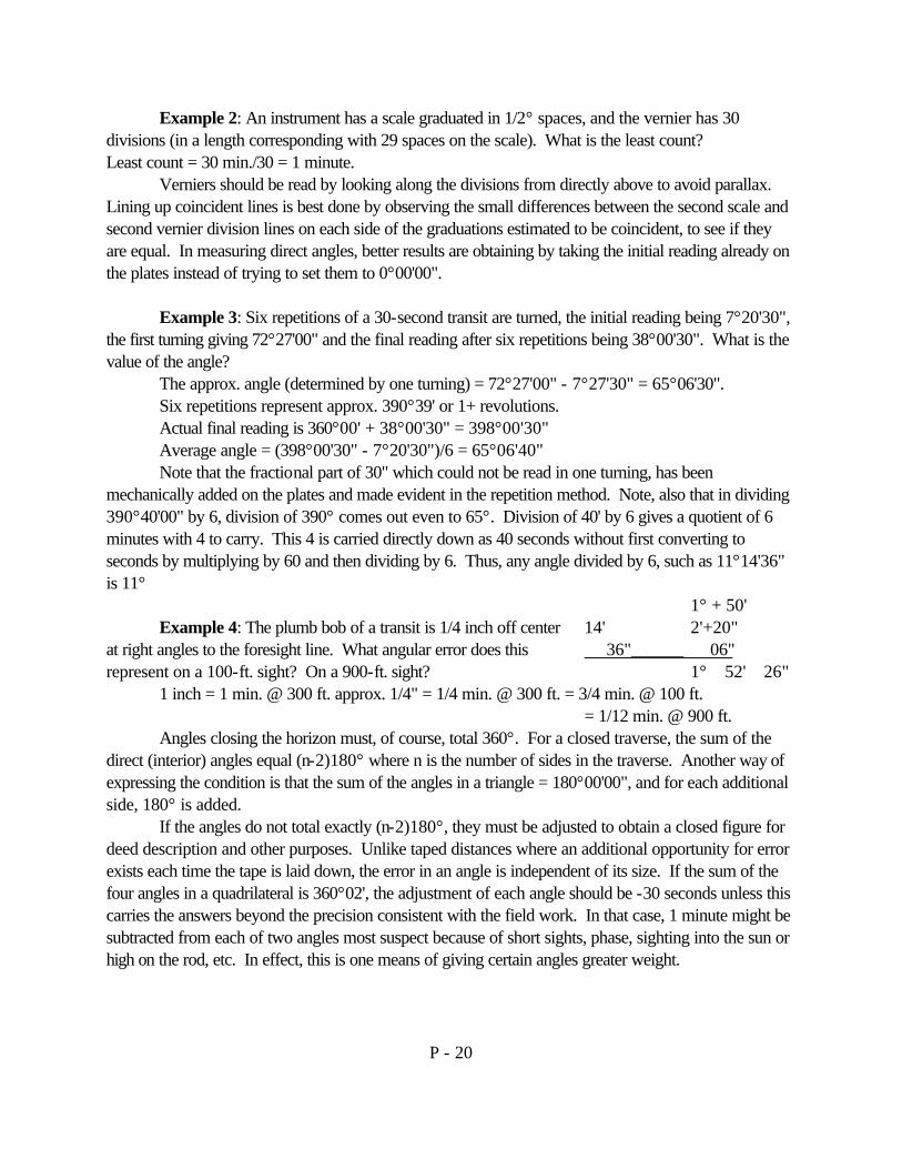
Example 2: An instrument has a scale graduated in 1/2° spaces, and the vernier has 30 divisions (in a length corresponding with 29 spaces on the scale). What is the least count? Least count = 30 min./30 = 1 minute.
Verniers should be read by looking along the divisions from directly above to avoid parallax. Lining up coincident lines is best done by observing the small differences between the second scale and second vernier division lines on each side of the graduations estimated to be coincident, to see if they are equal. In measuring direct angles, better results are obtaining by taking the initial reading already on the plates instead of trying to set them to 0°00'00".
Example 3: Six repetitions of a 30-second transit are turned, the initial reading being 7°20'30", the first turning giving 72°27'00" and the final reading after six repetitions being 38°00'30". What is the value of the angle?
The approx. angle (determined by one turning) = 72°27'00" - 7°27'30" = 65°06'30". Six repetitions represent approx. 390°39' or 1+ revolutions. Actual final reading is 360°00' + 38°00'30" = 398°00'30" Average angle = (398°00'30" - 7°20'30")/6 = 65°06'40" Note that the fractional part of 30" which could not be read in one turning, has been
mechanically added on the plates and made evident in the repetition method. Note, also that in dividing 390°40'00" by 6, division of 390° comes out even to 65°. Division of 40' by 6 gives a quotient of 6 minutes with 4 to carry. This 4 is carried directly down as 40 seconds without first converting to seconds by multiplying by 60 and then dividing by 6. Thus, any angle divided by 6, such as 11°14'36" is 11°
1° + 50' Example 4: The plumb bob of a transit is 1/4 inch off center 14' 2'+20"
at right angles to the foresight line. What angular error does this 36"______ 06" represent on a 100-ft. sight? On a 900-ft. sight? 1° 52' 26"
1 inch = 1 min. @ 300 ft. approx. 1/4" = 1/4 min. @ 300 ft. = 3/4 min. @ 100 ft. = 1/12 min. @ 900 ft.
Angles closing the horizon must, of course, total 360°. For a closed traverse, the sum of the direct (interior) angles equal (n-2)180° where n is the number of sides in the traverse. Another way of expressing the condition is that the sum of the angles in a triangle = 180°00'00", and for each additional side, 180° is added.
If the angles do not total exactly (n-2)180°, they must be adjusted to obtain a closed figure for deed description and other purposes. Unlike taped distances where an additional opportunity for error exists each time the tape is laid down, the error in an angle is independent of its size. If the sum of the four angles in a quadrilateral is 360°02', the adjustment of each angle should be -30 seconds unless this carries the answers beyond the precision consistent with the field work. In that case, 1 minute might be subtracted from each of two angles most suspect because of short sights, phase, sighting into the sun or high on the rod, etc. In effect, this is one means of giving certain angles greater weight.

P - 21
Adjustment of the angles does not make them correct - it merely provides results adding to the correct geometric total. A “pattern” type adjustment is desirable in a long traverse to expand or contract the traverse somewhat symmetrically, instead of applying all of the corrections to a few adjacent angles, unless knowledge of field conditions indicates the latter arrangement is closest to the probable truth. Angles must be adjusted before computing bearings, otherwise the bearings will not close the figure.
Some practical suggestions on transit work: 1. Center the instrument carefully over the station and level the head, then do not relevel between
back sight and foresight. 2. Align the vertical wire quickly, do not continue to stare at the target and change your mind. 3. Make final setting with the tangent screw by means of clockwise turning to prevent backlash. If
overrun, back off and turn clockwise again to compress spring. 4. Always check vertical arc for index error before starting work. 5. Close the horizon when reading several important angles from one station. 6. Always double-center important line prolongations, and measure deflection angles by repeating
an even number of times (2, 4 or 6). 7. When progressing generally in a straight line, have one pair of leveling screws along that line so
that cross leveling can be done with the other pair (the cross pair being the more important unless vertical angles are to be read).
8. Keep tripod legs tightened properly so there is neither play or strain. 9. Avoid sighting close to the ground, buildings and even bushes in generally open areas to prevent
unequal refraction bending the line of sight.

P - 22
TRANSIT, STADIA 1. The surveyor’s compass is an instrument which:
(a) reads horizontal angles. (b) gives the horizontal direction of a line. (c) is relatively free of all types of errors. (d) is an essential part of the engineer’s transit.
2. Accurate setting of the transit plates at zero is accomplished by means of the:
(a) upper tangent screw (c) lower tangent screw (b) upper clamp (d) lower clamp
3. When setting a transit over a tack point, by moving the leg of the tripod toward or
away from the plumb bob, the instrument man will: (a) change the level of the head considerably. (b) change the position of the plumb bob considerably. (c) change the position of the plumb bob slightly. (d) cause no change in the level of the head.
4. To read an angle by repetition, it is necessary to:
(a) set plates at zero before back sighting for each turning of the angle. (b) keep plates set at the value of the angle already turned when back sighting
for each turning. (c) turn angles with the telescope in the direct (normal position). (d) turn angles with the telescope in the direct and in the reversed (inverted position).
5. The most important detail to be observed in the procedure for measuring angles by
repetition with a transit is to: (a) turn the angle the same number of times with the telescope in the direct and the reversed
position. (b) turn the angle with the telescope in the direct position and the reversed position as
many times as are required, the precision varying directly with the number of repetitions.
(c) retain on the plates the value of the angle already turned when back sighting for each successive turning.
(d) always point the telescope on the object sighted by a clockwise motion of the upper tangent or slow motion screw.

P - 23
6. Turning angles with the transit telescope first in the normal or direct position and then in the reversed position corrects the error due to the: (a) plate bubbles not being at right angles to the vertical axis. (b) vertical hair not being truly vertical. (c) horizontal axis not being truly horizontal. (d) plates not being truly horizontal.
7. Prolonging a straight line with a transit by double centering or double reversing
nullifies the error caused by: (a) the vertical cross hair not being perpendicular to the horizontal axis. (b) the line of sight not being parallel to the axis of the telescope bubble. (c) the line of sight not being perpendicular to the horizontal axis. (d) the vertical cross hair not being truly vertical.
8. A random line in surveying is:
(a) an offset line for locating buildings. (b) a line produced to intersect a traverse line, or some other line. (c) a trial line run near a true line. (d) a line established by swinging a tape from a point to another line.
9. The stadia is a method for measuring:
(a) horizontal angles. (c) distances. (b) vertical angles. (d) differences in elevation.
10. The stadia method of surveying is used when:
(a) a rapid method of measuring distances over rough ground is required. (b) an accurate representation of a great amount of detail in a small area is required. (c) the survey is in open country. (d) the area surveyed is to be reproduced on a small scale map.
11. The stadia ratio or interval of a transit is:
(a) a constant quantity for all instruments and any one instrument. (b) the distance from the cross-hairs to the objective lens divided by the distance from
the center of the instrument to the cross-hairs. (c) the distance on the rod intercepted by the stadia hairs. (d) the focal length of the objective lens divided by the distance between the
stadia hairs. 12. The “stadia constant” of a transit is the distance from:
(a) the cross-hairs to the principle focus of the objective lens. (b) the cross-hairs to the objective lens.

P - 24
(c) the instrument center to the principle focus of the objective lens. (d) the instrument center to the objective lens.
13. In stadia surveying, the height of instrument must be known in order to determine the:
(a) elevation of the line of sight. (c) elevation of the observed point. (b) vertical angle to the observed point. (d) distance to the observed point.
14. Stadia readings can be taken with the rod held:
(a) plumb. (c) horizontal. (b) perpendicular to the line of sight (d) any of the above.
15. An error of 1 minute in the final reading of an angle means that the point is off per 100
ft. length approximately: (a) 3.0 (b) 0.3 (c) 0.03 (d) 0.003
16. Interior angle traverses are best suited to:
(a) route surveys. (b) property surveys of high precision. (c) topographic surveys for locating much detail. (d) stadia topography.
17. If it is necessary to climb over a fence in a field while carrying a transit or level, the
instrument man should: (a) lean the instrument against the fence, then climb over. (b) lay the instrument on the ground, then climb over the fence. (c) place the instrument on the other side of the fence with the tripod legs well
spread, then climb over. (d) remove the head of the instrument and place it on the other side of the fence.
18. The safest way to carry an engineer’s transit or level to prevent accidents under
various conditions encountered in the field is to: (a) keep the instrument head on the tripod with all clamps loose. (b) keep the instrument head on the tripod with all clamps tight. (c) keep the instrument in its box with all clamps loose. (d) keep the instrument in its box with all clamps tight.
19. The chief advantage of the transit-stadia method of surveying is the:
(a) the small size of party required. (b) the accuracy with which detail can be located. (c) the speed and ease with which contours can be located. (d) the general adaptability of the method to all types of surveys.
P - 25
10. A transit has a stadia interval of 101.0. For a distance of 100' but with the line of sight inclined downward at an angle of 12°° -00', the length intercepted on the rod will be most nearly: (a) 1.01 tan 12°. (b) 1.01 Cos 12°. (c) 1.01 (1/Cos2 12°° ) (d) 1.01 Cos212°
21. Lines AB and BC are two sides of a traverse being run by deflection angles from A to
B to C. The deflection angle at B is: (a) 36°45' R (c) 143°15' R (b) 36°35' L (d) None of these.
22. The bearing of AB is S 7°° 12' W, and the bearing of BC is N 86°° 13' W. The deflection
angle at B is: (a) 93°25R (b) 86°° 35'R (c) 256°35'R (d) 93°25'L (e) Answer not given.

P - 26
AZIMUTHS & BEARINGS
An azimuth is an angle measured clockwise from a meridian. The bearing of a line is the acute horizontal angle between the meridian and the line. A meridian is a reference line and may be the direction of true north or true south, magnetic north or south, or any assumed line. The true (geodetic) north-south line is commonly used because it can be checked and re-established by observations on the sun and stars.
The following problems arise in connection with azimuths and bearings: 1. Conversion of azimuths to bearings, and vice versa. 2. Conversion of true bearings to magnetic bearings, and fice versa. 3. Conversion of a magnetic bearing at some past date to that for the present time, or vice versa,
the declination (angular difference between the lines to true north and magnetic north) being different for the two dates.
4. Computation of the bearings of lines, given the actual or assumed bearing of one line and the angles between successive lines.
5. Correction of magnetic bearings effected by local attraction.
All of these problems are readily solved by means of a simple sketch or sketches. Keeping in mind these properties of azimuths and bearings will help avoid mistakes:
Azimuths Bearings 1) Values between 0° and 360° Values between 0° and 90° 2) Require numerical values only Require 2 letters and value 3) Can be true, magnetic, calculated, forward, back Same 4) Measured clockwise only Clockwise and counterclockwise 5) Measured from north only (or south only) in any survey Measured from north and south
Example 1: Convert an azimuth of 160° from north to its equivalent bearing.
The bearing angle is 180° - 160° = 20° The bearing is S 20°E
Example 2: The magnetic bearing of a line AB is N 27°10'W. The declination is 2°05'E. What is the true bearing of AB? (Note: True north is shown by a full-headed arrow, magnetic north by a half-headed arrow, the head being on the declination side to get it out of the way of the true north arrowhead. The true bearing=N25°05'W.
Example 3: The magnetic bearing of a property line in 1870 was recorded as N47°28'E. What is the magnetic bearing in 1959 if the magnetic declination is 1°15'W, but was 2°30'E in 1870? N51°13'E.
P - 27
Example 4: The bearing of AB, the west side of a subdivision forming a regular pentagon is due north. Compute the bearings of the other sides.
The short-hand method of computation shown is based upon having 1) a starting or reference line, 2) a direction of turning, 3) an angular distance. Clockwise angles are considered plus, and counterclockwise angles minus. At B, the angle is turned from the line BA as a back sight, therefore, the back bearing letters for AB are shown as SW in parentheses. The first letter, S, is then brought down to give the direction from which an angular distance of 108° is measured in a minus direction. This places the line BC in the NE quadrant with a bearing of N 72°00'E. The bearing of the first line should be computed as a check. If the bearing letters are not reversed as noted in the parentheses, alternate bearings will be correct, the others incorrect, even though a check on the computations appears to have been obtained. AZIMUTHS, BEARINGS 1) The magnetic bearing of a line is:
(a) the total horizontal angle measured from the south end of the magnetic meridian. (b) the total horizontal angle measured from the north end of the magnetic meridian. (c) the acute angle which the line makes with the meridian. (d) The azimuth of the line minus 90°.
2) The angle between the geographic meridian and the magnetic needle at any point is
known as: (a) deviation (b) variation (c) declination (d) deflection
3.) The clockwise angle which a line makes with any reference-line, is called the:
(a) bearing (b) declination (c) deflection (d) azimuth 4) A tangent line connecting Sta. 462+86.25 and Sta. 498+89.26 of a highway location
survey has a magnetic bearing of S 87°° 15' E. At Sta. 478+89.26 it crosses an existing highway whose bearing is S 62°° 15'W. The acute angle between the two alignments is: (a) 25°00' (b) 27°45' (c) 30°° 30' (d) none of these.
5) The bearing of a line AB is S 11°° 28'E. The interior angle at B turned clockwise to the
point C is 72°° 26'. The interior angle at C turned clockwise to the point D is 117°° 27'. The bearing of the line CD is: (a) N1°° 35'W (b) N9°53'E (c) S21°21'W (d) S 56°29'E
P - 28
6) An instrument man set up at point B of a traverse takes a back sight to point A and then reads a deflection angle to the line BC as 87°° 26' left. He checks the compass needle and reads the magnetic bearing of BC as N 72°° 30'E. The magnetic bearing of line BA is: (a) S14°56'E (b) N20°° 04'W (c) N14°56'W (d) none of these.
7) The magnetic bearing of a line forming part of a property survey in 1870 was recorded
as N46°° 28'W. At that time, the magnetic declination was 2°° 30'E. If the magnetic declination in 1943 is 1°° 15'W, the magnetic bearing of the line at the later date is: (a) N42°° 43'W (b) N45°13'W (c) N47°43'W (d) N50°13'W
8) The process of determining direction on a map relative to the earth’s surface is
generally called: (a) bearing (b) direction (c) geodetic (d) orientation (e) magnetic
9) An azimuth is always:
(a) equal numerically to the bearing of a given line. (b) 90° larger or smaller than the comparable bearing. (c) 180° larger or smaller than the comparable bearing. (d) between 0°° and 360°°
(e) answer not given. 10) The angle between the geometric meridian and magnetic needle direction of a line is
the: (a) interval (b) bearing © azimuth (d) deviation (e) declination

P - 29
MAPPING
A map is a representation on a plane surface, at an established scale, of the physical features (natural, artificial, or both) of a part of the whole of the earth’s surface, by the use of signs and symbols, and with the method of orientation indicated. Map scales may be given in three ways: 1) as an equality such as 1" = 400 ft.; 2) by a ratio or representative fraction such as 1:4,000; or 3) by a graphical scale (preferable scaled distances at right angles in diagonally opposite corners of the map.
Maps are classified as small scale (1" = 1,000 ft. or more), intermediate scale (1" = 100 ft. to 1" = 1,000 ft.), and large scale (1" = 100 ft. or less). The scale to be used depends upon the purpose of the map, size (dimensions) of a standard sheet, the type and number of topographic symbols to be shown, required plotting precision, etc.
Map drafting of small area maps consists of four phases: 1) plotting the traverse or control; 2) plotting the details; 3) plotting the topography and special data; and 4) finishing the map. Angles may be plotted by coordinates, tangents, protractor, or plotting machine. The coordinate method of laying out angles and distances for a traverse has the advantage that any error in plotting one point is not carried along into the next line.
Standard topographic symbols can be found in various manuals and publications and should be used on all maps. The meridian arrow selected should be simple and blend into the sheet. True north is indicated by an arrow with full head, full feather; magnetic north by half head, half feather, placed on the declination side of true north to provide maximum drafting clearance.
Titles of maps for individual organizations are standardized, but in general include the area location, scale, dates of field survey and map drafting, pertinent personnel, etc. Any notes required to outline special features of the map, and perhaps a legend, should be placed near the title to insure that they receive attention.
Example 1: What is the smallest unit of distance that can be plotted by a draftsman using ordinary equipment, on a map having a scale of 1" = 100 ft.?
Smallest scale distance generally plottable = 1/50" to 1/100" = 2 to 1 ft.
Example 2: If it is desired to keep plotting errors within 20 ft., what is the smallest scale that should be used?
20 ft. = approximately 1/50 inch. Then scale is 1" = 1,000 ft.
Example 3: Why do the features shown on a topographic map of a large area differ from those on a map of small scale?
Maps of large areas are probably to a small scale, thus making it impossible to depict some topographic features without considerable and undesirable exaggeration.

P - 30
Example 4: A traverse with all topographic details inside looks best on a sheet if the border distance to traverse corners is the same on the top, bottom, and left side. Determine the position for a 5-sided traverse on an 18" x 24" sheet having a 1" border on the left side and ½" on the other 3 sides. Coordinates of hubs are: A(0,0), B (+225.60, + 270.45), C(+78.76, +774.25), D(-67.34, + 564.58), and E(-405.57, +440.02).
Maximum possible scale = 774.25'/22.5" or 1" = 34 ft. Use 1" = 40 ft. For the Y-direction, 631.17/40 gives 15.8" required with 16 ½" available.
Then the border distance on 3 sides = ½ [17 - (631.17/40)] = 0.61". (ref. C p 300). 1. Maps are drawn to small scale when:
(a) the area to be represented is small (c) there is much detail to be shown. (b) there is little detail to be shown. (d) the size of the sheet is large.
2. A scale of 1" = 1000' would be called:
(a) a large scale (c) a small scale (b) an intermediate scale. (d) a natural scale
3. A scale of 1/20,000 would be called:
(a) an equivalent scale (c) a large scale (b) an intermediate scale (d) a natural scale
4. Graphical scales are shown on maps because:
(a) they enable the reader to determine distances more easily than with an equivalent scale.
(b) they give a more easily understood method of determining distances. (c) they improve the appearance of the map and serve to balance the meridian arrow. (d) maps are subject to change in scale.
5. In mapping, the term relief refers to such features as:
(a) rivers, lakes, harbors. (c) man made features. (b) vegetation. (d) shape of the ground.
6. In mapping, interpolation is the process of:
(a) spacing contour lines by proportion between lines. (b) drawing smooth freehand contour lines. (c) tracing contours on a plotted map. (d) connecting points of equal elevation.
P - 31
CONTOURS & CONTOUR LINES:
A contour is an imaginary line of constant elevation on the ground surface. It may be thought of as the trace formed by the intersection of a level surface with the ground surface, for example, the shore line of a still body of water.
If on a drawing are plotted the locations of several ground points of equal elevation, say, 720 ft. above sea level, a line on the map joining these points is called a contour line. Thus, contours on the ground are represented by contour lines on the map. Loosely, however, the terms contour and contour line are often used interchangeably. On a given map, successive contour lines represent elevations differing by a fixed vertical distance called the contour interval.
The use of contour lines has the great advantage that it permits the representation of relief with much greater facility, and with far greater definiteness and accuracy, than do other symbols. It has the disadvantage that the map is not so legible to the layman. TOPOGRAPHIC MAPS:
Characteristics of Contour Lines: The principle characteristics of contour lines can be illustrated by reference to Fig. 24-2. For the purpose of this discussion, the slope of the river surface is disregarded. The stage of the river at the time of the field survey was at an elevation of 510 ft., hence the shore line on the map marks the position of the 510 ft. contour line. For this map, the contour interval is 5 ft. If the river were to rise through a 5 ft. stage, the short line would be represented by the 515 ft. contour line; similarly, the successive contour lines at 520 ft., 525 ft., etc., represent short lines which the river would have if it should rise farther by 5 ft. Stages. Fig. 24-1. Hachures Fig. 2 Contour Lines

P - 32
The principle characteristics of contour lines are as follows: 1) The horizontal distance between contour lines is inversely proportional to the slope. Hence on
steep slopes (as at the railroad and at the river banks in Fig. 24-2), the contour lines are spaced closely.
2. On uniform slopes, the contour lines are spaced uniformly. 3. Along plane surfaces (such as those of the railroad cuts and fills in Fig. 24-2), the contour lines
are straight and parallel to one another. 4. As contour lines represent level lines, they are perpendicular to the lines of steepest slope. They
are perpendicular to ridge and valley lines where they cross such lines. 5. As all land areas may be regarded as summits or islands above sea level, evidently all contour
lines must close upon themselves either with or without the borders of the map. It follows that a closed contour line on a map always indicates either a summit or a depression. If water lines or the elevations of adjacent contour lines do not indicate which condition is represented, a depression is shown by a hachured contour line, called a depression contour, as shown at M in Fig. 24-2.
6. As contour lines represent contours of different elevation on the ground, they cannot merge or cross one another on the map, except in the rare cases of vertical surfaces (see bridge abutments of Fig. 24-2) or overhanging ground surfaces as at a cliff or a cave.
7. A single contour line cannot lie between two contour lines of higher or lower elevation. CONTOUR INTERVAL:
The appropriate vertical distance between contours, or contour interval, depends upon the purpose and scale of the map and upon the character of terrain represented. For small-scale maps of rough country, the interval may be 50 ft., 100 ft., or more; for large-scale maps of flat country, the interval may be as small as ½ ft. For maps of intermediate scale, such as are used for many engineering studies, the interval is usually 2 or 5 ft. CONTOUR MAP CONSTRUCTION:
Normally the construction of a topographic map consists of three operations: (1) the plotting of the horizontal control, or skeleton upon which the details of the map are hung; (2) the plotting of details, including the map location of points of known ground elevation, called ground points, by means of which the relief is to be indicated; and (3) the construction of contour lines at a given contour interval, the ground points being employed as guides in the proper location of the contour lines. A ground point on a contour is called a contour point.
P - 33
1. Interpolation in topographic mapping means:
(a) connecting points of the same elevation. (b) blowing up or reducing the map scale. (c) spacing contour lines by proportionate measurements. (d) drawing contour lines through points of known elevation. (e) drawing smooth freehand contour lines.
2. A closed hachured contour line represents a:
(a) ridge (b) valley (c) saddle (d) summit (e) depression 3. The sides of a highway tangent fill shown on a topographic map by contour lines are:
(a) straight, parallel and equally spaced. (b) straight but not parallel. (c) straight and parallel, but not equally spaced. (d) parallel and equally spaced, but not straight.
4. For a given map scale and contour interval, concentric circular contour lines might
indicate a relatively: (a) inclined plateau (b) great elevation (c) irregular or broken surface. (d) deep river valley (e) high isolated hills.
5. On a map drawn to a scale of 1" = 200 ft., contour lines are 3/8 in. apart at a certain
place. Contour interval is 10 ft. Ground slope in % at the place is: (a) 13.3 (b) 10.0 (c) 7.5 (d) 5.0 (e) 1.33
6. Contour interval is the:
(a) horizontal distance between adjacent contours. (b) elevation above sea level. (c) difference in elevation between adjacent contours. (d) scaled distance between adjacent contour lines on a map.
P - 34
TRIANGULATION:
Triangulation is a method of surveying in which the station points are located at the vertices of a chain or network of triangles. The angles of the triangles are measured by transits or theodolites and the sides determined by computation from selected sides termed base lines. The base lines are measured directly on the ground.
Triangulation permits the selection of sites for stations and base lines suitable from both topographic and geometric considerations, the latter involving choice of points which will give “strong” figures having angles larger than 30° if possible. The method is well adapted to the use of precision instruments and methods, and the production of accurate results. Triangulation is generally used where the area surveyed is large and the employment of geodetic methods desirable. It includes the operations of observing angles, measuring base lines, their mathematical processing, the reconnaissance which precedes these operations, and the astronomic observations required to establish a geodetic datum and control the triangulation.
Triangulation is now classified as 1st, 2nd and 3rd or lower order with appropriate specifications for each class. To obtain the results shown in the table, most work is done at night by sighting on lights and utilizing towers and mounting tops to get long sights. In the early haste to cover the United States, observations of 100 miles were not unusual and a maximum sight of 160 miles was taken. Most present day lines are probably closer to 25 miles. The wooden towers used in the past have been replaced by steel towers (actually 2 towers are used, the inner one for the instrument and a separate outer tower for the observer and the signal mounted above).
FIRST SECOND THIRD FOURTH Average triangle closure, seconds 1 3 6 6+ Maximum triangle closure, seconds 3 8 12 --- Check on base 1/25,000 1/10,000 1/5,000 1/5,000+
Triangulation results in the U. S. are reduced to the mathematical figure defined by the Clarke Spheroid of 1866. The basic point for the U. S. Is triangulation station Meade’s Ranch in Kansas which has the following position: Latitude 39°13'26.686", Longitude 98°32'30.506", Azimuth to station Waldo = 75°28'14.52". In 1927, the western half of the control net was adjusted, and the eastern half was similarly adjusted later. To identify positions and avoid confusion with older data, descriptions are noted as “North American Datum of 1927.” This is proper since the triangulation net has been extended both north and south of the U. S. Border. The symbol for a triangulation station is ∇. Stations established by the U.S.C.&G.S. are identified by circular bronze markers and their descriptions and positions made available free of charge to anyone who may wish to use the stations for control points.
Single triangles, central point figures, or quadrilaterals can be used for small areas, but generally chains or arcs of these figures are employed, as in Figure 1. A new based line is measured after about 10 to 30 triangles on 1st, 2nd and 3rd order work.
P - 35
The U.S.C.&G.S. net for the U.S. includes the equivalent of about 13 east-west areas and about 30 north-south areas with various crossings, internal areas, etc. Several electronic instruments now being used provide the means of measuring the lengths of long lines as accurately as it is possible to measure short base lines by older methods. As a result, trilateration, the measurement of all 3 sides of a triangle and computation of the angles may be employed in place of triangulation for some control purposes. A new electronic device for more accurately pointing theodolites is now being developed and should increase the precision of direction instrument sighting. 1. The main disadvantage of a precise traverse compared with triangulation is that:
(a) the accuracy is not of as high an order. (b) more calculations are required to determine all parts of the traverse. (c) a large field party is required to carry out the work. (d) the traverse usually is more expensive and all distances must be measured.
2. Disadvantages of a precise traverse compared with triangulation are:
(a) all angles must be measured by more repetitions for precise traverse. (b) all distances must be measured. (c) size of party is large. (d) fewer points are made available for the local surveyor.
3. Small angles are undesirable in triangulation because:
(a) they decrease the strength of figure. (b) they make computations more difficult. (c) they increase the cost of extending a chain of figures. (d) the intersection of the sides is poor thus increasing errors.
4. Since it is essential to keep horizontal refraction to a minimum, 1st and 2nd order
triangulation can best be done: (a) morning (b) noon (c) late afternoon (d) evening (e) night

P - 36
PRECISE LEVELS:
Precise leveling is the term formerly applied to first-order leveling, before the latter designation was recommended in 1925. Today, precise leveling is frequently used to describe the high precision work represented by first, second, and third order leveling. First order leveling is defined as follows: “Spirit leveling conforming to the following criteria: All first-order leveling is divided into sections of 1 km to 2 km in length; each section to be leveled over in both forward and backward directions; the results of the two runnings over a section not to differ by more than 4.0 mm times the square root of the length of the section in kilometers (4.0 K), the equivalent of which is 0.017 feet times the square root of the length of the section in miles (0.017 ft M).
Second-order leveling covers lines between bench marks established by first-order leveling and run in one direction, using first-order instruments and methods (or other lines divided into sections over which forward and backward runnings are made); the closure in either case not to exceed 8.4 mm times the square root of the length of the line in kilometers, the equivalent of which is 0.035 feet times the square root of the length of the line or section in miles (0.035 M).
Third-order leveling includes lines which are not extended more than 30 miles from lines of first or second-order leveling and must close upon lines of an equal or a higher order of accuracy; closing errors must not exceed 12 mm K), K in kilometers, which is the equivalent of 0.050 M.
Nearly all first and second-order leveling run by the U.S.C.&G.S. has been along railroads and highways. Almost half a million of the 3 5/8-inch diameter discs have been set for the use of all surveyors.
The levels used have higher magnification (about 43 diameters), more sensitive vials (about 1.7 seconds per division of approximately 1/16"), and utilize higher tripods to get the line of sight well above the ground. The rods used have an invar strip specially mounted in front, graduated in meters and decimal parts. The back of the rod is graduated in feet for checking. Three-wire leveling is employed, thereby providing an immediate check on the readings and the opportunity to average, as well as giving stadia distances for computing corrections if the lengths of plus and minus sights are not equal. The length of sight is varied as atmospheric conditions change, the maximum length being 150 meters.
An orthometric correction not considered in ordinary leveling is applied to correct for convergence of level surfaces in the north-south direction resulting from flattening of the earth between the poles. It amounts to more than 1 meter between San Diego and Seattle, and about 0.02 meters for Lake Michigan between Chicago (higher) and Milwaukee.
Example 1: A line of levels is run between two U.S.C.&G.S. bench marks, B.M. Rock and B.M. Mine which are 1.25 miles apart in order to establish a new B.M. en route for a bridge construction project. The difference in elevation for the listed elevations of the two B.M.’s is 22.478 ft., but a difference of 22.502 ft. is obtained. What order of leveling has been achieved?
Permissible closure for 1st order work is 0.017 1.25 = 0.017 x 1.12 = 0.019 ft. 2nd order work is 0.035 1.25 = 0.035 x 1.12 = 0.039 ft.
P - 37
The work is good second order since the closure is = 22.506 - 22.478 = 0.024 ft.
Example 2: What is the orthometric correction for a line of levels run north from B.M. A, elev. 270.0000 meters, Lat. 40°00' and B.M. B, Lat. 42°00', elev. 330.0000 meters? Mean elev. = 300.0000 meters. Mean Lat. = 41°00'. For Lat. 41° in table, k=0.000001523 Orthometric correction = 0.000 001 523 x 300 x (60' x 2) = 0.0548 m. (Subtract from B) 1) Field notes for precise leveling differ from those for ordinary bench mark leveling in
that they: (a) contain a column for intermediate foresights. (b) do not contain a column for foresights. (c) do not contain a column for the H.I. (d) do not provide a check on the arithmetic computations.
2. Starting from a point at elevation 897.152, a level circuit 3 miles in length closed on
this same point with 897.225. The class (order) of leveling is: (a) 1st (b) 2nd (c) 3rd (d) 4th (e) 5th
3. Refraction is caused by:
(a) the bending of light rays by the earth’s atmosphere. (b) observations being taken from the surface rather than from the earth’s center. (c) the failure of telescopes to focus properly for infinite distances. (d) uneven distribution of light over the field of view of the telescope.

P - 38
SLOPE STAKES, CROSS SECTIONS, EARTH WORK:
Slope stakes are set for construction purposes to show the intersection of side slope of cut or fill with the actual ground surface. To avoid less of the stakes in the construction process, particularly excavation, the stakes are moved out 1 ft. 2 ft., or an appropriate distance. Stakes set at the intersection of ground and grade are termed grade stakes. In the transition from cut to fill, and fill to cut, grade stakes are set on the center line and on the roadway edges to definite the limits of cut and fill which frequently zig-zag diagonally across the roadway. A full cross line of slope stakes is generally set for each grade stake.
Slope stakes are usually located by a trial-and-error method, using a level or a hand level and an ordinary level rod. Special rods and tapes are available but the trial-and-error method is fast and sufficiently accurate when performed by experienced personnel. The procedure followed is to estimate the cut or fill at the assumed slope stake point based upon the known cut or fill at the center line, then check the guess. Equations used mentally are C or F = Grade Rod - Ground Rod and Grade Rod = H. I. - Grade Elevation for that particular station. If within 0.1 to 0.5 ft, depending upon terrain and purpose of survey, the stake is set at the distance out computed from the cut or fill. If off more than the allowable range, move in or out, not exactly to the distance computed but a bit more or less depending upon the direction and rate of ground slope. Except in very difficult terrain, 1 or 2 trials should be sufficient for experienced men. Note that grades must be known before slope stakes are set, hence other steps such as center line profiles and cross sectioning usually precede this phase of the field work. A confusing point to the beginning is that at the point where a slope stake marked, say, C 2.0 ft., is set, there is NO cut, but stake is 2.0 ft. above grade elevation.
Cross sectioning consists in making measurements to define vertical sections of the ground surface at right-angles to the center line. It is usually done with a level or hand level and a cloth tape. Unlike slope staking, which stops at the limits of the earth work, cross sectioning is carried out as far as appears necessary or desirable to insure coverage of the construction line. Elevations are obtained at all breaks in the ground surface, and perhaps at multiples of specified distances such as 25, 50 or 100 ft., or at every contour interval. Other features, such as fence lines, are also located by their distances out from the center line. Suitable grades can be fitted to the plotted cross sections in the office. The station spacing of slope stakes and cross sections depends upon the type of terrain, accuracy required, and other factors, but 100 ft. stations are the maximum.
Highway departments are now utilizing photogrammetric means to develop cross section data from aerial photographs. Distances out and elevations are automatically obtained and stamped on cards or a tabulation sheet by an operator who makes settings on the stereo mode. Electronic computer programs have been set up to quickly calculate the data, locate slope stake positions, and determine areas and volumes. Several grade locations can be readily run for comparison of earth work quantities. Field location of slope stakes is then made from the computer notes.
Earth work quantities found from photogrammetric cross sections and slope stakes will be within a few percent of field values. Since it is not reasonable to get every slight ground undulation, tape and level results are not perfect standards in themselves. After some early

P - 39
doubts, contractors now accept photogrammetric results for earth work payments. Computations for earth work are based upon cross section areas consisting of 1) level sections,
2) three-level sections, 3) five-level sections, 4) irregular sections, 5) transition sections, and 6) side-hill sections.
Volumes are calculated by either the average-end-area formula, or the prismoidal formula. End area computations are simpler but tend to give slightly higher results. For example, the true (prismoidal) volume of a triangular pyramid is Ah/3 whereas the average-end-area volume is Ah/2, a difference of Ah/6 or 50%. This is the extreme case, but illustrates the fact that the difference between the two volumes, called the prismoidal correction, must usually be subtracted from the end-area volume to get the true volume. The formula for prismoidal correction for a triangular prism is Cp - ( l /12 x 27) (w1 - w2) (hl - h2), the factors being as shown in Figure 1. For a 3-level section, the prismoidal correction Dp - ( l /12 x 27) (c1 - c2) (D1 - D2). Note that the center sections, having equal bases, cancel out. For 5-level sections, Cp = ( l /12 x 27) (hr - h1) (Dr - D1). Note that the center sections, having equal bases, cancel out. For 5-level sections, Cp = ( l /12 x 27) (hr - h1) (Dr - D1). If prismoidal volumes are desired, it frequently is easier to compute average-end-area volumes and apply the prismoidal correction, than the compute prismoidal volumes directly. Unless otherwise stated in earth work specifications of a construction contract, average-end-area volumes are legally understood to be called for.
Formulas for various cross sections are given in the examples. Areas can also be found by 1) dividing the sections into triangles and trapezoids (which is what the formulas do), 2) by coordinates, or 3) by the matrix system.
Average-end-area volume V = L(A1 + A2)/2, A1 and A2 being areas of successive cross sections. Prismoidal volume V = L(A1 + 4A
m + A2)/6, Am being the area of the section midway between A1 and A2. Note that Am is NOT the average of A1 and A2 but is found by averaging the heights and widths and computing the area from them. Textbooks, handbooks, and special publications give tables and diagrams to expedite the computation of areas and volumes. Volumes can also be computed by the unit area or borrow-pit method, using either triangular or rectangular areas and multiplying them by the average of the three or four corner heights.

P - 40
Fig. 17.42 Slope stakes for a cross section in cut. slope stake, then from Fig. 17.42, when the slope stake is in the correct position (at C),
d = w + cs (17.68)
2 and
d = w + fs (17.69) 2
The following numerical example for a cut illustrates the steps involved in establishing the correct location for a slope stake in the field.
Example 17.9 - Let w = 20 ft. side slope s = 1 ½ to 1, and grade rod = 15.2 ft. Suppose that a slope stake is to be set on the left of the center stake (Fig. 17.42). As a first trial, the rod is held at A, ground rod = 6.6 ft. c1 = grade rod - ground rod = 15.2 - 6.6 = 8.6 ft. The computed distance for this value of c1 by Eq. (17.68) is w/2 + c1s = 10.0 + (8.6)(3/2) = 22.9 ft. Measurement from the center stake shows d1 to be 18.2 ft.; hence, the rod man should go farther out.
For a second trial, the rod is held at B; ground rod = 8.8 ft.; c2 = grade rod - ground rod = 15.2 - 8.8 = 6.4 ft.; w/2 + (c2)(s) = 10.0 + 9.6 = 19.6 ft. The measured value of d2 is 22.5 ft.; hence, the rod is too far out.
Eventually, by trial, the rod will be held at C; ground rod = 7.8 ft.; c = 15.2 - 7.8 = 7.4 ft. The computed distance for this value of c is w/2 + cs = 10.0 + (7.4)(3/2) = 21.1 ft. The measured value of d is also 21.1 ft.; hence, this is the correct location for the slope stake. The slope stake on the right, also set by trial and error, is 29.2 ft. right and has a cut of 12.8 ft. The notes for this final cross section are recorded as follows, where the symbol c designates a cut: c7.4 c8.6 c10.6 c12.8 21.1 18.2 0.0 29.2 The reading at 18.2 ft. left is recorded because it represents a break in the terrain.
Consider an example of slope stakes for a cross section in fill, as illustrated in Fig. 17.43. Fig. 17.43 Slope stakes for a cross section in fill.
Example 17.10 - let w = 7 m; side slopes 2:1; grade elevation at 32 + 00 = 240.36 m; center line elevation = 239.25 m.
A back sight on a B.M. gives the H. I. Of 241.90 m. The rod reading on center line is 2.65 m, which verifies the given center line elevation. The grade rod = H. I. - grade elevation = 241.90 - 240.36 = 1.54 m. In order to set the right slope stake, the rod is held, as a first trial, at point 1, where the ground rod = 3.23. Thus, f1 = grade rod - ground rod = 1.54 - 3.23 = - 1.69 m, where the negative sign indicates a fill. The computed distance for the absolute value of f1 by Eq. (17.69) is 3.5 +

P - 41
(1.69)(2) = 6.88 m. The measured value for d1 is 6.2 m, so that the rod must be moved farther from the center line.
A second trial is made at point 2, where the ground rod is 3.62 f2 - 1.54 - 3.62 = -2.08 m and the computed distance to f2 is 3.5 + (2.08)(2) = 7.66 m. Since the measured distance d2 is 8.2 m, the rod is out too far.
Eventually, by trial, the rod is held at 3, where the ground rod = 3.40, fr = 1.54 - 3.40 = - 1.86 m, the computed distance is 3.5 + (1.86)(2) = 7.22 m. This distance agrees with the measured distance dr; hence, point 3 is the correct location for the slope stake. The notes for this final cross section are:
H.I. 241.90
32 + 00 f0.56 f1.11 f1.86 4.62 0.00 7.22
where the left slope stake is also set by trial and error and the symbol f designates a fill. Slope stakes can also be set in the field by slope distance and vertical or zenith angle. This
procedure is particularly appropriate where the cuts are deep and fills or embankment are high, so that setting slope stakes from a single set-up of a level is not possible.
In Fig. 17.44, the instrument is set over the center line station with a height above the ground equal to the H.I. A sight is taken on the rod at A (the correct position for the slope stake) such that the rod reading AB equals H.I. and the vertical angle a or zenith angle z is observed. The difference in elevation between the center line station at D and the ground at the slope stake is A is BC = V, where
V = ll sin a = ll Cos z (17.70) and the horizontal distance from D to A is
d = l Cos a = l sin z (17.71) If c is the cut to grade elevation at the center line, taken from the profile and grade plans, the difference in elevation between the center line and the ground at the slope stake is (c + V) for an uphill sight and (c - V) for a downhill sight. Thus, the calculated distance.
P - 42
1) Cross-sections in route surveying work are taken usually (a) after the grade line has been decided upon. (b) to locate the limits of cut and fill. (c) for preliminary estimates of earthwork and to aid in selecting a satisfactory grade line. (d) to check quantities after construction has started.
(2) Cross-sectioning in route surveying is done to
(a) stake limits of cut and fill. (c) find grade points. (b) locate contours. (d) check quantities after construction has started.
(3) Cross-section leveling ordinarily consists of taking elevations at
(a) every full station. (c) every prominent point or break in the ground. (b) every change in grade. (d) every change in grade and angle point.
(4) Slope stakes are set to mark
(a) intersection of side slopes and natural ground. (b) limit and amount of superelevation. (c) limits of haul. (d) critical points in cross-sectioning.
(5) A slope stake is needed at the
(a) intersection of grade and ground service (b) point of grade change (c) intersection of side slope and ground surface (d) same location as cross section stakes
(6) Prismoidal and average-end area formulas used to compute earthwork volumes
(a) differ by a quantity equal to the prismoidal correction (b) usually give equal quantities for end sections having 4 or more sides (c) are exact for wedge-shaped solids (d) are generally given equal standing by law in contracts
(7) For two adjacent cross sections, one in cut and the other a straight line (zero section),
earthwork volume is best found by (a) average-end area method (b) DPD method (c) applying grade and ground rod (d) prismoidal method (e) coordinate method (f) matrix method
(8) The prismoidal and average-end area formulas for earthwork volumes
(a) always give equal results for triangular-ended prisms (b) always give results agreeing within an acceptable margin of error (c) apply only to 3- or 5-level sections

P - 43
(d) differ with the prismoidal volume usually being a larger value (e) correct answer not given
(9) The usual difference between volume of earth in a borrow pit and later embankment is
(a) waste (b) swell (c) shrinkage (d) subsidence (e) settlement (10) The prismoidal formula is more desirable than the average-end formula for computing
earthwork volumes when the (a) end areas are equal but cross sections differ slightly (b) end areas are equal and cross sections differ slightly (c) one cross section has a greater width but lesser center height than the other (d) two ends are level sections (e) all answers correct
P - 44
CONSTRUCTION SURVEYS
Construction surveying, like land surveying, receives a minimum of attention in textbooks, the assumption apparently being that its special applications must be learned by experience on the job using basic fundamentals. In general, construction surveys are reasonably straight-forward and without the legal and resurvey problems of land surveys. It has been estimated that 60% of all field surveying man-hours are occupied in construction surveys giving line and grade. Some details for a few types of construction layouts will be noticed briefly. On many jobs, permanent foresights (or back sights) are set at long distances on walls, piers, tripods, etc., to readily define primary construction lines.
For pipe line surveys, stakes are usually set every 100 ft on the centerline and a parallel offset line, and closer for larger pipes and on sharp horizontal and vertical curves. In some cases, stakes are desirable at every 1, 2, or 3 pipe lengths. The top of the cross batter board is set a full number of feet above the invert (lower inside surface) or flow line of the pipe. Measurements to the invert from the batter board are made by means of a graduated stick. A taut wire or string attached to nails driven in the batter board on the centerline give both line and grade.
Batter boards for building construction are set at all corners so that strings connecting nails in the boards will intersect at the outside corners of the walls. Occasionally batter boards are set inside the construction area if excavations for the basement and foundations do not interfere, or are not required.
Staking out (shooting) grades is approximately the reverse of profiling. It can be done with the instrument telescope level and changing rod readings (which is safer), or by throwing the bubble off center to provide the proper grade sight line on a computed rod reading.
Highway intersections having special features such as an overpass, underpass, clover leaf, etc., are best laid out by means of coordinates. Either highway can be selected as the X-axis (east-west), regardless of direction, and the other related to it. This permits a different field party to follow the work of its predecessor without confusion as to special reference stakes and methods of layout.
Bridge crossings longer than the standard 100, 200, or 300-ft tape lengths may require establishment of a triangulation system consisting of a single triangle or quadrilateral. A base line is laid out on one or both shores. One side of the figure can be the bridge or highway centerline, or an offset line parallel to it. Reference stakes for stationing are needed on the center line and an offset line beyond the limits of the bridge abutment construction. Bench marks should be made available within easy range of the abutments.
Example 1. What is the most important check that can be applied to the batter board staking for a building?
The diagonals should be measured and checked against each other, and against the correct computed value. Any discrepancy indicates an error in angle, or distance, or both. If the building has projections or insets, the diagonals for each rectangle must be checked.

P - 45
Example 2. Why does a surveyor frequently make measurements for buildings in terms of feet and inches instead of in feet and decimals of a foot?
The architects’ drawings are normally in feet and inches, and most workmen are more familiar with the carpenter’s rule than the engineer’s scale -- but they quickly understand decimal values when put on a dollar, dime and cents basis! (1) Batter boards usually give
(a) line. (b) grade. (c) line and grade. (d) sight lines.
(2) Building lines usually are run for
(a) the outside face of wall. (b) the inside face of wall. (c) the center line of wall. (d) indiscriminately.
(3) The alignment of forms for a long, medium height concrete wall can best be checked by
(a) a triangulation system. (b) an offset line. (c) marks on the forms. (d) marks on the walls.
(4) Deviations from the vertical of steel tubes driven to form cast-in-place concrete piles
are checked by (a) plumb line. (b) electronic plumb bob. (c) an electric light bulb on a line. (d) all of the above.

P - 46
PHOTOGRAMMETRY:
Photogrammetry is the science or art of obtaining reliable measurements by acrial photography (aerial photogrammetry) or by ground photography (terrestrial photogrammetry). Either vertical or oblique aerial photographs can be used. In stereophotogrammetry, stereoscopic equipment and methods are used. Stereoscopy is the science and art which deals with stereoscopic effects and the methods by which they are produced. The stereoscopic principle is the formation of a single, three-dimensional image by binocular vision of two photographic images of the same terrain taken from different exposure stations. With proper equipment, all measurements needed in map construction can be made from this visual model. Stereoscopic fusion is that mental process which combines the two perspective images on the retinas of the eyes in such a manner as to give a mental impression of a three-dimensional model. A stereoscopic pair in photogrammetry consists of two photographs of the same area taken from different camera stations in such a manner as to afford stereoscopic vision.
Photogrammetry is not a control type method of surveying, rather it requires control and its main use is in preparing topographic maps for which it has the advantage of 1) speed of coverage, and 2) complete coverage of all details (unless obscured by ground cover or vertical slopes) regardless of the inaccessibility of the area.
A vertical photograph is not an orthographic projection or a map. In addition, photographs may not be truly vertical and require correction for tilt and tip, as well as for differences in elevation of the camera and displacements of points due to relief.
Tilt is the angle at the perspective center between the perpendicular to the photograph and the plumb line - or more simply, it is the result of the camera being turned about the flight line to the right or left. Tip is caused by the camera being elevated forward or backward along the flight line instead of being vertical.
To properly tie in photographs and control, permit use of stereoscopic equipment, and assure coverage of the desired area, photographs in adjacent flight lines are taken with a designed amount of end lap (usually 60%) and side lap (usually 20%).
The accuracy attainable with precise plotting equipment is best given as a ratio of the flying height, for example, 1/5,000. Elevations to less than 0.5 ft. can be guaranteed under proper conditions, and one-foot contours are now commonly provided under rigid contract specifications. A semi-automatic plotting device which traces contours automatically but requires some operator supervision to keep contours off buildings and trees in the stereo model, is now in initial production and promises to further advance the art and science of photogrammetry.
Example 1: The photo distance between two points is 2 inches. The ground distance is 3,000 feet. What is the scale of the photograph?
S = 2"/(3000' x 12) = 1/18,000
Example 2: An aerial camera with a focal length of 6 1/4" is used to take photos at an altitude of 7,000 feet above sea level. What is the scale of the photographs if the average elevation of the ground is 2,000 feet?
P - 47
The scale formula for perfectly flat terrain is S = __F__where f is the focal length of the camera, H = altitude of the plane H - h above the datum, and h = elevation of terrain above the datum. S = 6 1/4______ = __1_
12(7,000-2,000) 9600 Example 3: What is the effective coverage in acres of a 9" x 9" photo in Example 2? S = 1/9,600 or 1" = 800 ft. Area covered = 9" x 9" = 7200' x 7200' = 51,840,000 sq. ft. = 1,190 acres.
X - Photogrammetry
1. Photogrammetry is the science of
(a) plotting maps using the stereoscopic principle (b) surveying or map making by means of measurements on photographs (c) compiling plan views from selected contact photo prints (d) interpreting details shown on photographs
2. Photogrammetry is defined as (c) photo interpretation
(a) aerial surveying (d) photo image measurements (b) measurement of ground distances (e) study of photo relief
3. The most efficient type of shutter used in aerial photography is the
(a) focal plane (c) between the lens (e) curtain (b) louver (d) rotary
4. The principal point of a photograph is the
(a) plumb point (c) mechanical center (b) collimation mark (d) point of known elevation
5. A true “oblique” aerial photograph
(a) always shows the apparent horizon (b) can also be a vertical aerial photograph (c) is taken with the camera axis intentionally inclined to a vertical line. (d) is not suitable for mapping purposes
6. Tilt of an aerial photograph
(a) is defined as the angle between the camera axis and a vertical line (b) prevents its use for mapping purposes if over about 1. (c) can be eliminated by proper manipulation of the stereoscope (d) is defined as the angle between the plane of the photograph and a vertical line

P - 48
7. The scale of an aerial photograph is predetermined by (a) altitude at which taken (d) altitude and focal length of camera (b) focal length of camera used (e) mean datum of job (c) size of an area to be covered
8. If the print distance is 2.5 inches and the ground distance is 2500 feet, the scale is
(a) 1:12000 (b) 1:1000 (c) 1:2500 (d) 1:30000 (e) 25:2500 9. Before photographs can be studied with a stereoscope, the must
(a) be matched (c) have a different scale (e) have contrast (b) have some tone (d) be properly oriented
10. Overlap is
(a) usually an exact percentage of the side lap (b) measured parallel to the flight line (c) not necessary for stereoscopic viewing (d) the portion of a photograph covered by the two adjacent photos
11. Proper stereoscopic overlap of two aerial photos is
(a) 20% (b) 30% (c) 40% (d) 50% (e) 60% 12. A mosaic
(a) includes at least four photos. (b) includes at least two adjoining strips. (c) is assembled or plotted to a definite scale. (d) is not defined by any of the above.
13. The largest present use of mosaics is
(a) to replace topographic maps. (c) construction of relief maps. (e) illustration. (b) substitute for topo-maps. (d) stereoscopic study.
14. The prime requisite of a completed mosaic is
(a) appearance. (c) accuracy in detail placement. (e) neat trim lines. (b) good color. (d) neat matching of all points.
15. The focal length of an aerial camera lens is
(a) the exact distance from face of film to front surface lens. (b) the exact distance from face of film to rear surface of lens (c) the exact distance from face of film to geometric center of lens. (d) none of the above.

P - 49
“HIGHWAY BOUNDARY DETERMINATION GUIDELINES” Highway Boundary should be located at whichever of the following is the furthest out from the existing centerline of road: a) 1 rod(16.5' or 5.03 M) minimum from the oldest centerline of record. All town roadways in
New York prior to 1957 were opened to 2 or more rods wide according to the Laws in force at the time they were opened, and the width set by the town when they were opened. Exceptions to even this minimum width have been found, but generally a 2 rod minimum is appropriate. This requires researching old town meeting records and historical maps of the area to determine what width the roadway was originally laid out as. After 1957, all new town roads were to be opened to a minimum of 3 rods wide, [Hwy Law -- Sect. 189]. Since many state and county highways were once town roads, this applies to them also.
b) A locally recognized highway user width which is utilized by most of the Land Surveyors who
have done surveys on the developed parcels along the subject highway. The width is usually, but not always, 3 rods (or 49.5') wide and is centered around the existing centerline. This boundary is determined by comparing the location of property corner markers with deed descriptions or private survey maps and determining their reasonable reliability.
c) The outer limit of the public’s prescriptive easement which includes all traveled ways and
shoulders, drainage and bridge structures, public sidewalks, roadside ditches, retaining walls and slope stabilization which support and protect the integrity of the highway. The line that delineates this public user easement defines what area is necessary for the continued use of the highway by traveling public (either by vehicle or on foot), as well as what is needed to maintain the existing highways roadway and appurtenances by the responsible authority. Any used width has to reflect public use for a time period of greater than 10 years, [Highway Law -- Sect. 189]. Any modern structures built by private owners upon previously occupied and maintained highway boundary does not constitute ownership and is therefore an encroachment onto the highway boundary. There is no adverse possession against lands held in trust for the traveling public.
Sidewalks are “as much a part of the highway as the traveled wagon-way is, and it is under the care, superintendence and regulation of the same authorities”, (case law People vs. Meyer, 1899) [Highway Law -- Sect 2, Note 4]. A sidewalk is by definition [Vehicle & Traffic Law Sect. 144] a part of the street.
d) The original record plan occupation limits. This information is sometimes sketchy at best, but
it represents the best information available on the user width of a highway when it was jurisdictionally transferred to the State, [Ch 115 in Laws of 1898 & Ch. 468 in Laws of 1906], or on a county road when the County originally opened the road as a county highway, [Highway Law -- Sect. 115].

P - 50
“RIGHT-OF-WAY DETERMINATION GUIDELINES” Highway Right-of-Way should be determined utilizing the following order of important evidence: a) Every attempt should be made to find and accurately locate the original baseline that was
used to describe previous acquisitions. The baseline points may be buried under inches of pavement or in some undisturbed wooded areas. These points represent the highest order of accuracy in re-establishing the limits of takings. If the actual points can not be found, but the ties are still in existence, every effort should be made to locate the ties and re-establish the baseline points from the ties.
b) The second order of evidence that should be located would be any permanent survey
markers within the project area which were set from the same baseline from which acquisitions were made. These PSM’s can be used to rotate into the coordinate system of the original baseline and thus the ROW limits. These PSM’s have to first be checked to determine their reliability prior to holding them for control.
c) The third order of important evidence would be field located right-of-way monuments. The
field monuments should be inversed between and compared to theoretical inverses from acquisition maps to determining reliability of their locations. The best fits would be held for small contiguous areas of acquisitions. Clusters of ROW takings separated by areas with no takes or by intersecting roadways should be analyzed on separate ROW coordinate bases, and attempts should not be made to force for entire project length off a single set of monuments. In some cases, physical structures such as building corners, bridges or walls can also be held in conjunction with ROW monuments to substantiate to appropriate hold points.
d) The final technique available for re-establishing right-of-way is by overlaying the original
mapping over the topographic mapping from the field and determining hold points for the “best fit”. These hold points may include, but not be limited to: center lines, bridges or cross culverts, buildings and stone walls. Once hold points are determined, the right-of-way lines should still computed from the baselines and offsets shown on the taking maps.
Note: After right-of-way limits are established, keep in mind that highway boundary prescriptive rights
may extend beyond the ROW due to public use or maintenance responsibility extending beyond the right-of-way.

P - 51
“TURNPIKE BOUNDARY DETERMINATION GUIDELINES” Former Turnpike Boundaries in New York State should be determined utilizing the following proof of evidence: a.) Between 1797 and 1847, all turnpikes or plank roads were created by individual acts of the
state legislature. Turnpike laws of 1807 & 1827 set up general provisions which would apply for all turnpikes created between 1807 and 1847, but the individual turnpikes were still incorporated by individual acts, [Chapter 38 of 1807 and chapter 18 of 1827]. All turnpikes after 1847, [Chapter 210 of May 7, 1847], could incorporate without legislated action, but were required to apply to the county Board of Supervisors for authority to construct the road and acquire the necessary real estate.
b.) Turnpikes constructed before 1848 or after 1890 are a minimum of 4 rods wide, and in a few
cases 6 rods wide, (unless stated as less in the statute). Any turnpike constructed between 1848 and 1890 has a minimum of 4 rods unless specifically stated to be less in the commissioner’s survey or in the inspector’s report.
c.) Evidence necessary to show that the turnpike was actually constructed would include some of
the following:
1.) State legislated act which created a turnpike corporation (<1847). Research in the “Index to the Session Laws” under Turnpikes ans Plank Roads. “Articles of Association” filed with the Secretary of State (check “Notices of Incorporation”). Remember, state acts relating to the same turnpike found at a later date than the incorporating act, would be evidence that the corporation existed and implies that the road was constructed.
2.) County legislation which created a turnpike corporation (>1847). Research in the county clerk’s office or county board of supervisors office for old meeting minutes, or research the “Index to Corporation” in the county clerk’s office.
3.) Newspaper notices of turnpike corporation formation. 4.) Centerline survey to be filed in the county clerk’s office (check map index). A few
original surveys have been found to represent general locations of roads and were not intended to detail the exact centerline of the turnpike. Some old maps can be found in the archives of the NYS Education Dept.
5.) Turnpike statutes authorized corporation to acquire necessary land rights by purchase or condemnation. It is unclear, in many instances, whether turnpikes purchased real estate in fee or purchased easement rights from the owners of record to construct a turnpike or plank road.
6.) In many cases, no one lay claim to the land so the corporation petitioned the count judge, who with the assistance of a jury, determined whether compensation was
P - 52
necessary, (Check for “Inquisitions” in grantor index of county clerk’s office). 7.) Some turnpikes were previous Public Roads . These roads had either been acquired
from the adjacent owners or they represented user easements over adjacent properties. Any improvements already made to these Public Roads were appraised and paid by the turnpike corporation to the municipality. The turnpike could only acquired the same rights that the Public Road has (fee or easement).
8.) Turnpike corporations filed annual financial reports with the State Comptroller prior to 1847, and then with the Secretary of State after 1847.
9.) Some turnpike mile markers still exist and/or are shown on old maps (ie.: Beer’s Atlas for example).
10.) Old patent maps or atlases show locations of turnpikes and tollgates. Local historians can also be helpful in proving existence of a turnpike.
11.) Adjacent owner deeds which refer ro the turnpike running along the property. Be wary of occasional referrals to turnpikes in deeds due to local nick names attached to local roads, which may not necessarily reflect the actual route of an original turnpike.
12.) The oldest centerline of record can be determined from: original centerline surveys, record place, old survey maps, old survey notes, field monumentation or topography, and adjacent deed descriptions.
d.) The Courts have held the following presumptions:
1.) There is NO Adverse Possession against lands held in trust for the people of the State of New York for highway purposes.
2.) The presumption that if evidence of the roadway exists today and provided there is proof that the turnpike company existed, then the land to the full width prescribed by law was acquired either in fee or as an easement by the turnpike company. It is further presumed that turnpike corporations fully complied with the procedures outlined in the governing statute, even if all the pertinent documentation can’t be found.
3.) Assuming the original centerline survey can not be found, the oldest field centerline of record is the centerline of the original turnpike.
4.) The burden of proof is entirely on the state to determine the termini and width of a turnpike.

P - 53
DEFINITIONS Abstract Request Maps Once properties being affected by a proposal project are identified, the designer should submit to the Regional Right of Way Mapping Group a “base map”. Base maps are described in detail in Chapter 3 of the “Right of Way Mapping Procedure Manual.” This submittal should include design files if the project is mapped electronically. From the base map, and other original and filed maps and information, the Right of Way Mapping Group will develop an Abstract Request Map. An Abstract Request Map (ARM) is prepared to obtain the necessary title data for the property to be acquired by the project. It provides the Department of Law with a means of identifying the properties for which title data is required. The ARM will vary in size depending upon the scope of right of way required for the proposed project. The designer should consult the project schedule to determine when this information needs to be available. ARM’s generally must be submitted to the Real Estate Division a minimum of 18 to 24 months before a project is to be let to contract. Right of Way Determination The designer should include proposed taking lines on the working plans, encompassing the areas required to construct, operate and maintain the proposed facility. The designer shall allow room beyond the construction limits (toe or top of slope) for construction equipment and for future maintenance operations. Generally, a minimum of 1.5 m should be used where the right of way costs are high. A distance of approximately 4.5 m is desirable when it can be obtained with little extra cost or impact to the adjacent property. Consideration should be given to visual aesthetics, maintenance procedures, roadside safety, “Guidelines for the Adirondack Park”, future development and disruption to adjacent property owners in determining taking lines. Discussion with all involved units should occur early in the design process to ensure all impacts are fully evaluated. Taking lines should avoid as many angle points as possible. When angle points in the taking lines are necessary, they should generally be kept a substantial distance from property lines which are transverse to the roadway, to avoid being mistaken for property line corners between adjacent owners. After determining right of way taking lines, the designer will meet with the Real Estate Group, and the Right of Way Mapping Group to review taking lines (Taking Line Review Meeting). At this meeting, a final determination is made regarding size and type of taking to be mapped.
P - 54
Right of Way Plan The right of way plan is a graphic summary of all the right of way acquisitions required on a project. It shows the impact of the project on each property affected. It also shows the relationship of one property acquisition to another. It is a useful tool to the Real Estate Group both in appraising affected properties, and in negotiating acquisition settlements with property owners. A right of way plan is required on all projects in which federal funds are used for right of way activities (including funding for either ROW Incidents or ROW Acquisitions), and is required in order to secure authorization for ROW Acquisitions. The right of way plan is prepared after Design Approval at a time when the project’s final design has sufficiently progressed to determine the limits of construction work required. It is prepared and approved in accordance with the “Right of Way Mapping Procedure Manual” and Engineering Instruction, E.I. 91-23 Right of Way Plan Approval. All right of way easement information shall be shown on the final plans in the manner indicated in Chapter 21, Section 21.2 of this manual. Types of Right of Way Right of way is usually acquired by appropriation. Appropriation is the taking of property by the government through the power of eminent domain. When a parcel of land is taken in fee, owner’s rights to the parcel of land are acquired by the State of New York. Lands taken in fee are generally used to accommodate road sections and the foundations needed to retain them. When easements are taken, the State’s rights are limited to the purposes stated in the easement. Permanent easements are taken to accommodate highway appurtenances, and may also be used in place of fee taking to avoid disproportionate impact to a remainder property. Temporary Easements and Occupancies are taken to accommodate the construction of a project. The following are different types of right of way easements: 1. Fee, with Access -- the right to access the road from abutting property remains 2. Fee, without Access -- the right to access the road from the abutting property is denied 3. Permanent Easement -- some of an owner’s rights to a parcel of land are permanently taken.
For example, the State might take those rights needed to construct and maintain a ditch pr pipe, while allowing the property owner to retain the use of the property for other purposes which do not interfere with the purpose of the easement.

P - 55
4. Temporary Easement -- some of an owner’s rights are taken to accommodate the construction, but not the future maintenance of a project. Temporary easements must be used where use of the land is critical to construction or where anticipated compensation to the owner reaches a certain monetary threshold prescribed in the New York State Eminent Domain Procedure Law (currently $2500). Temporary easements must be used to take title to a structure, ie. a shed or sign structure.
5. Temporary Occupancy -- some of an owner’s rights are temporarily taken for purposes which
are less than critical to the construction of a project, and compensation to the owner is less than $2500. (See Real Estate Division Program Procedure EN-RE-504 for details on the use of T.E.’s and T.O.’s.) Temporary occupancies can be used for purposes such as minor grading and ditching.
6. Entrance, Approach, or Driveway Work Release -- the owner allows the State to enter their
property, without reimbursement to reconnect their driveway, sidewalk or other approach to the road’s alignment. Provision for reestablishment of driveways is covered by Section 54a of the Highway Law. No temporary easement or temporary occupancy maps are used for this purpose.
7. General Work Release -- the owner allows the state to enter their property without
reimbursement to accomplish work which is mutually beneficial to the Department and the property owner. Examples include flattening of back slopes, minor ditching and tree removal.
Encroachments Encroachments exist on many highway right of ways. Generally, the owners should be requested by Highway Maintenance to remove these encroachments. However, and encroachment may be allowed to remains if it can be shown that the structure in no way impairs or interferes with the free and safe flow of traffic on the highway. Encroachments are allowed to occur when a “Use and Occupancy Permit” has been granted, however FHWA must approve an encroachment that remains on a federal-aid project. The designer, in consultation with the other program area groups, may recommend to the Regional Director that the encroachment remain. If approval is granted, the Real Estate Group is responsible for managing the encroachment. ROW MAPPING PROCEDURES MANUAL NOTES ROW acquisition is authorized at the time of phase authorization. When a project requires ROW where none was anticipated, the designed is responsible for obtaining authorization. This includes transfer of jurisdiction of state lands.
P - 56
Phase I Design Engineer schedules a take line meeting to discuss ROW impacts and ARMs. Plans should indicate extreme taking anticipated based on all alternatives.
Phase II ROW forwards ARMs to Real Estate for advisory agency review. Phase III Public Hearing after public meeting, Design prepares Design Report. Mapping Unit
shall have property lines and boundary line completed by beginning of Phase V. Phase IV The Design Engineer, early in Phase IV, will submit to the ROW Mapping Unit a base
map for ARM for the balance of the properties affected by the recommended alignment. ROW will complete information on ARM’s and assign a temporary reference numbers (TRN). Prints of the completed ARM’s are sent to Real Estate with a request that title data be obtained. An estimated date for Abstracts of Title is required. Judgement should be exercised in requesting this data prior to design approval. Scheduled needs for the data must be weighed against possible design changes. Real Estate makes preliminary acquisition cost estimate that determines the degree of title required. The request is sent to Main Office Real Estate and forwarded to the Attorney General’s Office. ROW Mapping completes deed and map search. Existing property lines, highway boundaries, easements and ROW are determined. This information is then placed on the plans for designer’s information and in preparation to drafting any appropriation map required. Maps should show existing topography, property line monumentation, baselines, easements, all means of access, property owner’s name and acreage.
Phase V Advance Detail Plans. The Design Engineer should program work so that a take line meeting occurs early in Phase V. A joint review is scheduled with Real Estate and ROW Mapping to discuss proposed take lines and type of acquisition. Project design should have advanced to the point were the following information is available: a. Existing topography including underground features, septiss, wells.... b. Tops and toes of slopes are plotted. c. Control of access indicated. d. Drainage completed to the extent that easements are shown. e. Purpose of easements stated. f. Design layout showing items such as proposed sidewalks and drainage facilities. g. Utilities and relocations shown.
During the taking line review, a mapping priority will be established as follows: U.S. Government lands Cemeteries Properties w/buildings State lands under other department jurisdiction Railroad holdings Parks and Recreational areas

P - 57
After taking line review ROW Mapping provides Real Estate with the following information needed to schedule their work:
a. Number of maps required b. Number of first map c. Date first map will be completed d. Date last map will be completed
For Federal participation in ROW acquisition, refer to ROW Mapping Procedure Manual. If estimated ROW acquisition cost is more than $50,000 than Federal Aid will be requested. This request is made at the time of project initiation. ROW maps submittal -- ROW Mapping Unit forward original tracings (signed) to Real Estate. A set of prints is forwarded to Design Engineer for review. ROW Map -- The Real Estate Group makes a Report of Physical Inspection (RPI). Conflicts observed during field inspections is brought to the attention of ROW Mapping. Inquiries by Attorney General’s Office are sent to ROW Mapping via M.O. Real Estate with a copy to the Regional Real Estate. Inquiries must be answered before Certification of Title is made. Revisions made prior to filing in the County Clerk’s Office requires preparation and submittal of a new tracing of revised map. Maps may be withdrawn prior to filing County Clerk’s office with a request signed by the Regional Director. After Certification of Title is received, Regional Real Estate must receive approval from Regional Design through the ROW Mapping Unit to have the map filed in the County Clerk’s Office. Phase VI Final Contract Plans -- Designer is responsible for transferring all ROW data on the
contract plans. ROW Mapping Unit is requested to review plans for accuracy. Real Estate Division, M.O. notifies Regional Director of pending letting and requests that a certificate be furnished to their office identifying PIN numbers, S.H. name and number and county of maps required. (4-6 weeks prior to letting) Certificate of Maps Required form ROW 253-1 and 253-2a are submitted to Regional Director and M.O. Real Estate. ROW Mapping furnishes prints of ROW Maps to EIC with two sets sent to the Contractor. Temporary Easements -- T.E. Maps are filed in County Clerk’s Office and must be terminated when easement is no longer required. The EIC initiates termination procedures (usually payment is made on a time-rent basis). The construction supervisor notifies Real Estate that easements are no longer necessary. Temporary Occupancy Maps do not need to be filed. Payment is on a time-rent basis. Misc: Advance Acquisition may be considered to prevent imminent development of property
or to relieve a hardship caused to the owner.
P - 58
TERM AGREEMENT: I. SCOPE OF SERVICES The work of the contract shall consist, in whole or in part as directed, of surveying and mapping services required for specific projects in the Department of Transportation capital program. Work under TASS agreements includes, and is limited to, the work units listed here. Standards for all surveys will conform to those given in the NYSDOT’s current Surveying Standards & Procedures Manual. Unit 1: Global Positioning System Surveys: This unit includes planning, conducting, adjusting, and reporting surveys accomplished through application of Global Positioning System technology. Coordinates will be in the New York State Plane Coordinate System, using the NAD 83 or NAD 83/93 horizontal datum, as specified; elevations will be on the NAVD 88 vertical datum. Installing new monuments for GPS surveys falls under work unit 11. Unit 2: Horizontal Control: This unit consists of terrestrial surveying operations to extend coordinates from existing horizontal monuments to and through the project site, establish baseline and other control points within the project area, and close the survey on an existing control monument. The Department may specify existing control monuments to be used and new points to be positioned. Coordinates will be in the New York State Plane Coordinate System, on the horizontal datum specified by the Department. Unit 3: Vertical Control: This unit consists of the terrestrial surveying necessary to extend elevations (Orthometric heights) from existing bench marks to and through the project site, establish bench marks and other vertical control points within the project area, and close the survey on an existing bench mark. The Department may specify existing bench marks to be used and new point elevations to be determined. Elevations will be on the vertical datum specified by the Department. Unit 4: Topographic Surveys: This unit consists of the precise field location and description of topographic and cultural features as specified. Typically, this work includes, but is not limited to, digital terrain models, base mapping, field edits of existing mapping, topics studies, bridge site surveys, stream crossings, soundings, scour surveys, route surveys, railroad crossings, or supplemental field surveys in areas of dense vegetation. Unit 5: Utility Surveys: This unit includes coordination, office work, and field procedures related to identifying, locating, and marking existing utilities within the project site. It may include supplementing information obtained through photogrammetry. All above ground utility data and all underground utility data are included in this unit. Power, telephone poles, etc., may be located by field survey. Pole numbers and wire traces may be obtained by review of individual utility company records and by field investigation. Cables, pipe lines, underground tanks, etc., shall be identified by type, size and location.
P - 59
Unit 6: Drainage Surveys: Information shall be obtained in the field for all drainage structures, e.g., size, material, type, and invert elevation at inlet and outlet. Additional data may sometimes be required, such as information on watershed areas or channel descriptions and cross-sections. Unit 7: Property Surveys: This unit includes all field work done to support property identification and ROW mapping. It consists of two sub-units: (7A) property inventory and (7B) physical property survey. A property inventory (7A) consists of an inventory of all property lines together with a listing of the reputed owners and type and use of building thereon. These data will be plotted on maps as accurately as possible considering the best sources of information. Physical property surveys (7B) determine the most accurate location of all property lines within a work area; lines are located from the baseline monuments and plotted on stable planimetric or topographic maps together with all building and ownership data. Unit 8: ROW Mapping: This unit includes any or all of the several phases of ROW mapping including research of existing maps, records and deeds, preparation of abstract request maps; preparation of individual fee appropriation or easement maps, temporary occupancy maps, maintenance site maps, scenic enhancement maps, defacto maps, control access maps and appropriation of reserved rights. This unit also includes preparation of abandonment maps, conveyance maps, claim maps and transfer maps. Preparation of key maps and/or ROW plans is also included in this unit. All work will be done in accordance with the Department of Transportation ROW Mapping Procedure Manual. Unit 9: Photogrammetric Control: Projects to be mapped photogrammetrically require supplemental control for the analytical aerotriangulation process. It consists of 2 subunits: (9A) horizontal and vertical control and (9B) targeting. Under 9A, the SURVEYOR shall survey the targets and/or picture points selected by the Department. Individual photogrammetric control points may serve as horizontal control, vertical control, or both. Every effort shall be made to include these points in the baseline or side traverses or level lines. Subunit 9B consists of placing targets for photogrammetric control. The configuration of the targets will be specified by the Department. The locations of targets will be indicated by the Department on targeting diagrams. These locations may be adjusted by the consultant to meet existing field circumstances. Unit 10: Cross-Sections: Cross-sections shall be measured and plotted by the SURVEYOR along an alignment, and at intervals and offsets, specified by the Department. Side alignments and additional sections to capture specific features may also be specified. Vertical and horizontal plotting scales will be specified.

P - 60
Unit 11: Control Point Monitoring: This unit consists of all work involved in physically setting new survey monuments. It might also involve resetting damaged or destroyed monuments. Survey work required for positioning these monuments would fall under units 1, 2 or 3. Unit 12: Special Surveys: This unit is intended to provide for all other surveying and mapping activities concomitant with Department projects not specifically covered by one or more of the other units described herein. Examples of such services may be construction surveys including stakeout, special site surveys, court appearances, special analysis of survey measurements. Unit 13: Photogrammetric Mapping: This unit consists of obtaining metrically controlled aerial photography, performing analytical aerotriangulation adjustments, performing digital stereo compilation, and producing finished digital 2D and 3D mapping products. The delivered products will conform to the Department’s existing standards and specifications for photogrammetric mapping. Unit 14: Reduction of Field Data: This unit consists of office work to reduce, balance, and adjust raw field data and measurements. Unless otherwise specified, coordinate values and azimuths for all control points shall be grid coordinates and grid azimuths on the appropriate N.Y.S. Plane Coordinate Zone as specified by the Department. Elevations (orthometric heights) shall be adjusted to the concomitant vertical datum. Specific digital data formats and magnetic media may be specified by the Department for delivery of survey coordinate data. Unit 15: Drafting or CADD Operations: This unit consists of developing and/or finishing hard copy or digital mapping products derived from survey data collected under other units of this agreement. Specifically excluded from this unit are products generated under Unit 8, ROW Mapping. Digital products, whether 2D or 3D, will be delivered in Intergraph file formats on the medium specified by the Department. Graphic products shall conform to the specifications, guidelines, and practices established by the Department. Information on these requirements will be made available to the consultant upon request.

P - 61
SURVEYING (LEVELING): 1) Which of the following errors and sources of error in leveling is usually not chargeable
to the rod man? A. Rod not tested for length B. Rod not held exactly on point C. Level out of adjustment D. Dirt on the bottom of the rod
2) In leveling, which of the following would be an accumulative error:
A. Level out of adjustment B. Graduation of rod C. Human error
3) A leveling rod reading taken for the purpose of determining the elevation of the point
on which the rod is held is known: A. Line of site reading B. Plus sight rod reading C. Minus sight rod reading D. Back sight rod reading
4. Assume that in differential leveling, between the two bench marks the sum of the
foresights equaled 5.00' and the sum of the back sights equaled 30.00'. If the elevation of the first bench mark is 25.00', the elevation of the second bench mark is: A. 0.00 B. 5.00 C. 25.00 D. 30.00 E. 50.00
5. Assume that a leveling rod, supposed to be 10' in length, is 0.001 of a foot too long. If
the error is distributed uniformly over its entire length, what correction in feet should be applied for an apparent difference in elevation of 500 feet? A. 0.00 B. 0.05 plus C. 0.05 minus D. 0.10 plus E. 0.10 minus
6. Assume that bench levels on a highway and bridge survey have been run from a
U.S.G.S. bench mark in order to establish the elevation of ten new bench marks. The check run reveals an error of 0.5'. Which one of the following is the most practical procedure to follow in order to establish satisfactory bench mark elevations and expedite the work? A. Divide the error equally among the ten bench marks B. Divide the error equally among the ten bench marks taking only half of the error C. Divide the error among the bench marks where an error was most likely to occur D. Ignore the error and use the elevations determined E. Re-run the bench levels

P - 62
7. Assume that while obtaining the difference in elevation of two points, the bubble of the level leaves the center of the tube a slight amount between back sighting and foresighting. Which one of the following would be the most practical procedure to follow in order to obtain the correct difference without re-leveling? A. Take the foresight reading without re-leveling B. Take the back sight reading without re-leveling C. Center the bubble and take the foresight reading D. Adjust the level tube by the peg method
8. Linear feet on a level rod are subdivided into:
A. Inches and eighths of an inch B. Inches and tenths of an inch C. Inches and sixteenths of an inch D. Tenths and hundredths of a foot E. Hundredths and thousandths of a foot
9. Which one best indicates how a leveling rod should be held when leveling? (In
reference to the line of sight) A. Parallel B. Parallel to the plane of sight C. Perpendicular D. Perpendicular to the ground surface
10. The elevation of a turning point may best be determined by deducting the leveling rod
reading from the elevation of: A. Bench mark B. H.I. C. The plus sight D. The back sight
11. The elevation of a bench mark is 106.47. A level is set up and a rod reading of 8.21 is
taken on the bench mark. The H. I. is: A. 98.25 B. 99.26 C. 112.26 D. 114.68
12. From an H. I. of 61.21, a foresight is taken on a turning point. The rod reading is 6.40.
The elevation of the turning point is: A. 67.62 B. 54.81 C. 64.82 D. 63.82 E. 67.82
13. Errors of adjustment of the level may be eliminated by:
A. Using two different levels and averaging the results B. Holding the umbrella over the level C. Making all back sights less than 100 feet long D. Making all foresights less than 100 feet long E. Making the back sights and foresights equal in length
P - 63
14. The difference in elevation between two accessible points may be determined most accurately by: A. Differential leveling B. Rod readings and vertical angle C. Rod read. & hor. angles D. Chained dist. & vert. angles E. Chained dist. & hor. angles
15. In leveling, when plus and minus sights must be made unequal, as in crossing a wide
river, which of the following leveling methods should be used to avoid errors of curvature, refraction and adjust. A. Profile B. Barometric C. Reciprocal D. Area
16. A plum bob is used for:
A. Running levels B. Chaining C. Nailing red eyes in pavement D. Digging ditches
17. What advantage does direct leveling have over target leveling?
A. Accuracy B. Speed C. Shorter sights 18. In leveling when it is found that the level is out of adjustment, what would be the best
thing to do to finish days work? A. Use two levels and average the readings B. Make all back sights equal to each other C. Make all foresights equal to each other D. Make back sights and foresights equal to each other
19. With level set up midway between stations “A” and “B”, reading on “A” was 3.15 and
that on “B” 4.33. Then the level was moved close to station “B” and rod reading recorded as being 4.85 on Sta. “B”. What is the correct rod reading on Sta. “A”? A. 3.67' B. 6.03' C. 5.67'
CHAINING 20. A cloth tape would most likely be used in which one of the following types of surveys?
A. Cross-section B. Measurements to ties C. Baseline D. Centerline E. Bridge stake out

P - 64
21. When chaining up a slope, the rear chain man should hold the tape in which one of the following positions? A. On the ground B. Level, using a plum bob C. Same as the head chain D. Parallel to the ground
22. The best way for a head chain main to hold a 100' tape when he is chaining down a
slope is: A. At the same elevation above the ground as rear chain man B. At eye level using the plum bob C. Stretched lightly along the ground D. Level, using the plum bob
23. A rear chain man when accurately measuring a horizontal distance with steel tape
should do which one of the following: A. Split hairs when lining in B. Drop chain as soon as measurement is made C. Keep in the line of sight when transit man is sighting D. Find the exact point which marks the end of tape
24. Which chaining errors are most often cumulative?
A. Irregularities on the pull of the tape B. Incorrect readings of the graduations C. Failure to correctly mark the end of the tape for each measurement D. Failure to straighten the tape for each measurement
SURVEYING (TRANSIT) 25. The device used for reading fractional divisions of angles on surveying instruments is
called a: A. Protractor B. Planimeter C. Compass D. Vernier E. Stadia
26. The reason for making the peg test of a transit is to:
A. Make the horizontal axis perpendicular to the vertical line of sight B. Make the horizontal axis perpendicular to the vertical line of sight C. Make the bubble of the plate perpendicular to the horizontal line of sight D. Make the bubble of the scope parallel to the horizontal line of sight
27. When turning a transit to sight on the first point in order to repeat the measurement
for an angle, which of the following motions should be kept clamped? A. Upper B. Lower C. Upper & Lower D. None of the above
P - 65
28. When running a traverse, deflection angles are obtained most accurately by which one of the following methods? A. Double defection B. Continuous azimuths C. Magnetic bearings D. Reverse centering
SURVEYING (ANGLES AND TRAVERSES) 29. The difference between the reading of 108°° -16' and 62°° -34' is:
A. 44°- 42' B. 45°° - 42' C. 45°- 82' 30. An angle was recorded as 63°° - 12' the first time it was turned. It was then turned an
additional 5 times. What is the average angle if the final reading was 19°° -14'? A. 63° - 12' - 40" B. 63°-11'-40" C. 63°° -12'-20" D. 63°-13'-20"
31. Magnetic bearings are used in surveying principally to:
A. Establish a base line meridian datum on reconstruction survey B. Determine declination of the locality C. Check the local attraction D. Office check the azimuth E. Field check the azimuth
32. The length of course times what function will give the departure of the course?
A. Cosine B. Tangent C. Sine D. Secant 33. The latitude of a traverse course is equal to the length of the course multiplied by
which one of the following functions of the bearing of the course? A. Sine B. Cosine C. Tangent D. Cosecant
34. In a traverse the sum of the latitudes differs by 8.00' and the sum of departures differs
by 10.00'. The error of closure of the traverse is: A. 9.00' B. 13.00' C. 19.00' D. 26.00'
35. A closed traverse of a land survey has the following uncorrected latitudes and
departures: Line Latitudes Departures “AB”..........................4000.00'................................. 0.00' “BC”.......................... 0.00'.................................4000.00' “CA”........................-3994.00'.................................-3992.00' The error of closure for the condition above is: A. 7.00' B. 8.00' C. 10.00' D. 14.00' E. 6.00'

P - 66
36. Balancing a survey means: A. Leveling the plate bubbles on the transit B. Making all sights equal lengths C. Adjusting the field work to correspond to the geometric values D. Correct the angles to fit the traverse
37. When taking stadia shots in stadia surveying, the rod is held in which one of the
following conditions? A. Plumb B. Perpendicular to the line of sight C. Perpendicular to the ground surface
SURVEYING (STADIA) 38. Which one of the following errors is LEAST important in ordinary stadia surveying?
A. Errors in reading of the rod B. Errors in measuring the angle (vertical) C. Errors in measuring the horizontal angles D. Errors in using incorrect stadia interval factor E. Errors caused by unequal refraction
39. The measured distance between the center of the transit and the rod is 600.00'. The
reading of the rd: 6.77' for the top hair and 0.82' for the bottom hair. The stadia interval for this transit is: A. 99.17 B. 100.84 C. 100.72 D. 100.93
40. Assume that for a given stadia sight between two stations the plus vertical angle was
8°° -40', the calculated vertical distance “V” was found to be 22.00', the line of sight reads 5.70' on the rod, the H.I. (Height of Instrument) was 4.20'. The difference in elevation between the two stations is: A. 20.50' B. 23.50' C. 26.20' D. 27.70' E. 31.90'
TRIANGULATION, RANDOM LINES, TOPOGRAPHY, CONTOUR LINES: 41. Triangulation would most likely be used in which type of below enumerated survey?
A. Preliminary survey for a new highway B. Preliminary survey for the grade elimination C. For a bridge to be built across a river D. Laying out the center line for a highway

P - 67
42. In which one of the following cases would a random line be used? A. To locate an inaccessible point B. For excavation of a bridge pier C. To locate a point discernable from the transit D. In dense woods where the point to be located is not readily seen but the general
direction of the line is known 43. In highway reconstruction survey topography is usually located by which one of the
following methods? A. Stadia B. Coordinates C. Angle and distance
44. Information from which one of the following types of surveys is generally least used in
the preparation of contour maps? A. Aerial reconnaissance B. Preliminary C. Final D. Topographic E. Stadia
SURVEYING (AREAS OFFICE WORK) 45. New highway surveys should be run in which one of the below enumerated directions?
A. Easterly or southerly B. Westerly or northerly C. Westerly or southerly D. Easterly or northerly E. Easterly or westerly
46. A field is surveyed with the transit and a steel tape. Its area is computed to be 100.00
acres. After the computations are made, it is found that the tape is 100.05' long instead of 100.00' long as previously assumed. The actual area is? A. 99.80 acres B. 99.90 acres C. 100.10 acres D. 100.20 acres
47. Assume a steel tape, nominal length of 100.00' was used to measure distances of a
closed traverse. From these distances the area enclosed by this traverse was computed to be 100.00 acres. The tape was later tested and found to be 99.93' long. What is the correct area of the traverse? A. 100.14 B. 99.86 C. 100.24 D. 99.76
48. An area is bounded by 60.00 chains on one side and 200.00 chains on the other.
Acreage of the area is: A. 1200 B. 12000 C. 120 D. 12
49. Apparent length of the line that was measured with 300.00' tape at 30 degrees is
1000.00'. When compared with the standard tape at 70 degrees, the 300.00' tape was found to be 0.03 feet too long. Coefficient of expansion is 0.0000063. The true length of the line measured is:
P - 68
A. 1000.15 B. 1000.25 C. 999.85 D. 999.75 50. Line “AB” is 100.00' running due east. Line “BC” is 200.00' running due north. Line
“CD” is 300.00' on a bearing of N 60°° W. Find the length of “AD”: A. 200.00' B. 385.00' C. 450.00'
51. A traverse may be plotted most accurately by the use of which one of the following:
A. Coordinates B. Protractor and scale C. Natural tangents & scale D. Plane table & stadia board E. Tangent offsets and scale
SURVEY (DECLINATION & AERIAL): 52. A line of an old survey is recorded as N18°° -00' E magnetic bearing. After a re-survey,
it now reads N 16°° -30' E magnetic bearing. Which one of the following represents the change in declination in direction and amount? A. 1°° -30'E B. 1°-30' W C. 1°-30'N D. 1°-30'S E. 88°-30'W
53. A point is given on a map and the elevation of the point is 147.30' and another point
with the elevation of 151.30'. These two points are 20' apart. Find the distance between contour lines of the elevation 148.00' and 150.00'. Scale is 1" to 5'. A. 1" B. 2" C. 3" D. 2 ½"
SURVEY (DECLINATION AERIAL): 54. Of the following, the most important purpose of the aerial surveys is to:
A. Expedite new highway locations B. Give better control points for surveys C. Pin point the locations where grade separations are required
55. A stereoscope would most likely be used in connection with which one of the following
types of surveys? A. Aerial B. Plane table C. Compass D. Stake out E. Stadia
56. Photogrammetric maps which have been carefully prepared to a scale of 200' per inch can be
used to estimate the yardage of excavation for a selected new highway lines. Such estimates may usually be considered to be accurate to within which one of the following percentages of the actual excavated quantity? A. 1% B. 5% C. 15% D. 20% E. 25%
57. The following steps are given for an outline of the method that should be used when making an
P - 69
aerial survey for alternate route reconnaissance. 1. Prepare photogrammetric maps 2. Examine photographs under the stereoscope 3. Fly over flight lines and take photographs 4. Lay out flight lines 5. Locate control points in base map sheets 6. Run ground traverses and base lines to locate control points and establish bench marks
with level parties Place above enumerated steps in their proper sequence: A. 4, 3, 2, 6, 5, 1 B. 4, 3, 1, 2, 5, 6
SURVEYS (GENERAL): 58. A transit is used to:
A. Run the base line B. To spy on people C. Dig ditches D. Measure accurate horiz. dist.
59. Thirty spaces on a transit vernier are equal to 29 spaces on a graduated circle of the transit.
One space on the graduated circle of the transit represents 30 min. The vernier reads direct to: A. 15 Secs. B. 20 Secs. C. 25 Secs. D. 30 Secs. E. 1 min.
60. The plum bob is held ½ inch off the line, 600 feet away from the transit. The resulting angular
error will be: (ACE - 1965) A. 1° B. 1 min. C. ½ min. D. 1/4 min.
61. In reporting an angle with the transit:
A. The lower motion is kept clamped B. The upper motion is kept clamped C. The lower motion is kept unclamped D. The upper motion is kept unclamped E. The angle is measured with the lower motion clamped and the transit turned
back to the first point with the upper motion clamped 62. In measuring horizontal angles with a transit, errors of adjustment may be eliminated by:
A. Reading both verniers B. Repeating all angles three times C. Having two different men read the angle D. Reading all angles on the vernier E. Measuring each angle an equal number of times with the telescope erect and with the telescope erect and with the telescope inverted and averaging the readings
63. In case of rain, when there is no waterproof hood or other means at hand for sheltering the

P - 70
transit, the transit man can best protect his instrument by: A. Turning the telescope objective end down with the cap over the lens B. Leaving the telescope in a horizontal position with the cap over the lens C. Removing the eye piece and keeping it in a dry place
64. When adjusting the line of sight of a transit to be perpendicular to the horizontal axis of
revolution, the transit is set up over the point B of the line AB. Then the point A is sighted with the transit erect and the transit plunged. Point X is set up on this line. The transit is then turned in azimuth and point A sighted again with the instrument inverted. The transit is plunged again and point Y is set. To make the necessary adjustment, the vertical wire of the telescope should be moved to cover (ACE-1965). A. A halfway between points X and Y B. A quarter of the distance from Y to X C. A quarter of the distance from X to Y D. Point X E. A halfway between points Y and X
65. An angle was recorded as 105°° 18' for the first reading and was then turned three
additional times, after which the plate reading was 61°° 11'. The probable value of the angle is: A. 105°17'30" B. 105°° 17'45" C. 105°18'00" D. 105°18'15"
66. In transit operation, the angle recorded the first time is 33°° 50'20". After the fourth
reading, the angle of 135°° 57' was recorded. The probable value of the angle is: A. 33°° 59'15" B. 33°56'45" C. 33°56'15" D. 33°57'00"
67. In stadia surveying, differences of elevation are computed from:
A. Rod reading alone B. Rod reading and horizontal angles C. Rod reading and vertical angles D. Chained distances and the vertical angles E. Chained distances and the horizontal angles
68. In stadia surveying, the horizontal distances are computed from:
A. Rod reading and horizontal angles B. Rod reading and the vertical angles C. Chained distances and the vertical angles D. Chained distances and the horizontal angles E. Length of a previously measured base line
69. In stadia surveying, the constant “f + c” refers to:

P - 71
A. The elevation of the transit telescope B. The distance from the eye piece to the center of the telescope C. Vertical distance between the stadia cross hairs D. Focal length of the telescope plus the distance from the center of the instrument
to the objective lens E. Focal length of the telescope plus the distance from the eye piece to the objective lens
70. To determine the stadia constant of a transit, a rod is read at a measured distance of
300' from the transit. With the transit telescope horizontal, the rod readings are 4.17 on the lower cross hair, and 7 15 on the upper. The constant “f+c” has been measured and found to be 1.1'. The constant “f/i” is: A. 99.40 B. 99.70 C. 100.00 D. 100.30 E. 100.60
71. Correction for temperature is most likely to be required in:
A. Length of a level rod B. Computation of “sun shots” C. Length of a steel tape used in measuring the center line D. Length of the tape used in measuring a baseline for triangular E. Reduction of notes from a stadia survey
72. The coefficient of expansion of steel is .0000065. With a 30°° increase in temperature,
a 100' steel tape will expand about: A. 1/100" B. 2.100" C. 1/8" D. 1/4"
73. Approximately how much will a 100' steel tape increase in length with a rise of
temperature of 100°° F? A. 1/4" B. 1/2" C. 3/4" D. 1" E. 1 1/4"
74. A point may be located from a survey base line by measuring its:
A. Double meridian distance B. Angle C. Station and right angle offset D. Double parallel dist.
75. Where a stream is too wide to stretch a tape across it, the distance across the stream
may be accurately measured by: A. An odometer B. Triangulation from a baseline on one side of the stream C. Swimming across and measuring D. Measurements across the nearest bridge
76. A steel tape is supposed to be 100' long. The apparent length of the horizontal line
measured with this tape is 1640.51 ft. After the measurement is completed, the tape was checked with a standard and found to be 100.03 ft. long. The true length of the

P - 72
line is: A. 1625 B. 1630 C. 1639 D. 1640 E. 1641
77. The apparent length of a horizontal line measured with a 100' tape is 2,500'. After the
measurement was completed, the tape was compared with a standard and found to be 99.96' in length. The true length in feet of the measured line is: A. 2197 B. 2498 C. 2499 D. 2501 E. 2502
78. Assuming zero azimuth being north, what is the bearing of a lineAB having an azimuth
of 144 degress? A. S 36 E B. N 54 E C. N 54 W D. S 36 W
79. The back azimuth of the above line is:
A. 324 B. 244 C. 55 D. 36 80. When north is the direction of zero azimuth, a line of 175°° azimuth will have a bearing
of: A. S 5 W B. S 25 W C. S 5 E D. S 25 E
81. When north is the direction of zero azimuth, a line of 215°° azimuth will have a bearing
of: A. W 55 S B. S 35 E C. S 35 W D. E 55 S E. E S 55 W
82. The bearing of a line AB is N 42°° 20' E and of a line AC is S 15°° 30'. The value of the
angle BC is: A. 58-50 B. 73-30 C. 104-40 D. 121-10 E. 148-50
83. The magnetic declination at a given point is found to be 9-45 east. The magnetic
bearing of the true E is: A. N80-15E B N99-45E C. N90-45E D. N80-45E
84. The algebraic sum of the deflection angles of a closed traverse should equal:
A. 0° B. 90° C. 180° D. 360°° 85. Coordinates of a point are given as N 2,400 and E 300. A line having a bearing of S
35°° E and a distance of 200 feet is laid out. The coordinates of the new point at the end of this line will be: (ace 1985) A. N2230 E406 B. N2570 E194 C. N2570 E406 D. N2230 E194
86. In polaris observation, the star crosses true north:
A. Once in 24 hours B. Twice in 12 hours

P - 73
C. Twice in 24 hours D. Four times a day 87. The hand level is used to:
A. Establish elevation of bench marks B. Adjust the wye level C. Run lines of check levels D. Extend the cross sections E. Adjust the transit88. A right angle prism is used for: A. Running baseline B. Measuring angles C. Turning right angles D. Turning left angles
89. Elevations on grade stakes are usually measured to:
A. Inch B. Foot C. Tenth of an inch D. Hundredth of a foot E. Eighth of an inch
90. In cross sectioning a road, ground elevations are usually measured to the nearest:
A. Foot B. Inch C. Tenth of a foot D. Eighth of an inch E. Hundredth of a foot