surveying manual bphc_first cycle
DESCRIPTION
Surveying Lab Manual Cycle 1TRANSCRIPT
BIRLA INSTITUTE OF TECHNOLOGY & SCIENCE - PILANI
HYDERABAD CAMPUS
SURVEYING LABORATORY MANUAL
By Prof. V VINAYAKA RAM
DEPARTMENT OF CIVIL ENGINEERING AUGUST 2013
Birla Institute of Technology & Science, Pilani Hyderabad Campus Jawahar Nagar, Shameerpet Mandal Hyderabad 500078, Andhra Pradesh, India
Tel:
Fax:
Email:
Web:
+91 40 6630 3509
+91 40 6630 3998
www.bits-hyderabad.ac.in
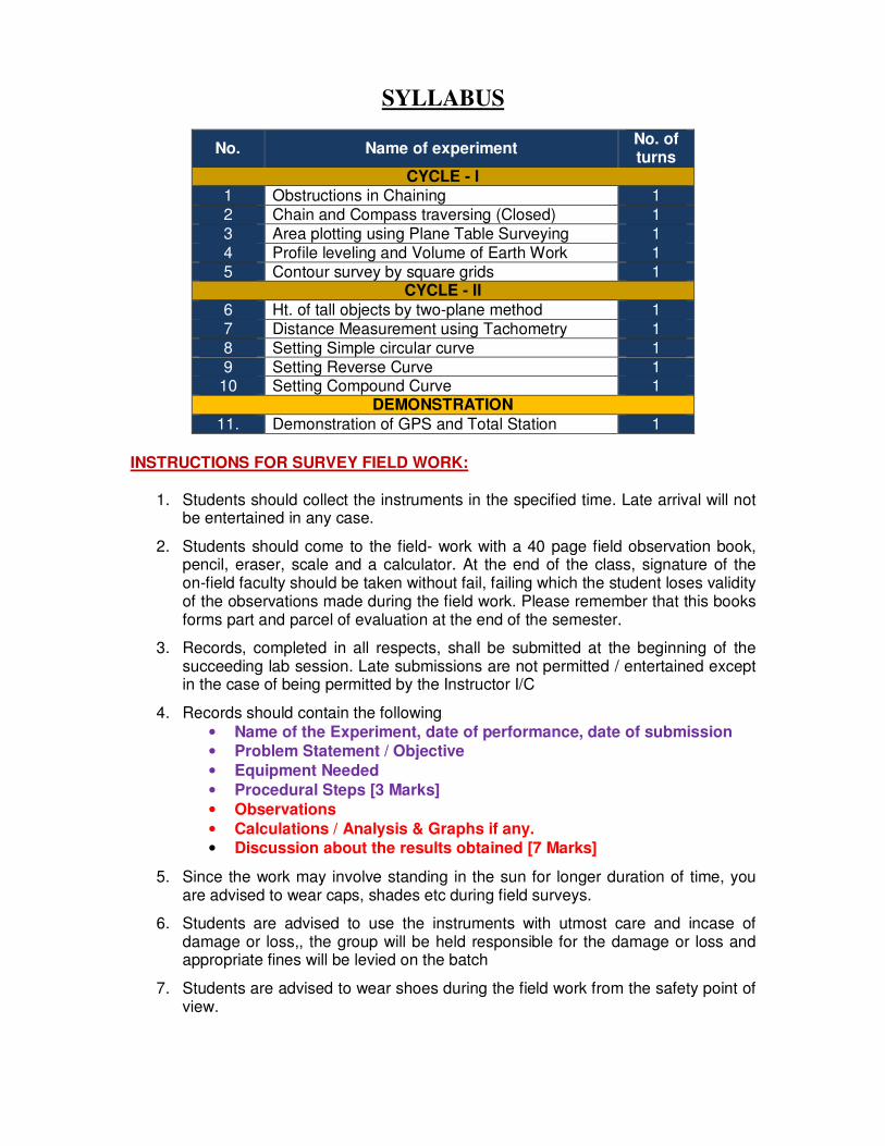
SYLLABUS
No. Name of experiment No. of turns
CYCLE - I 1 Obstructions in Chaining 1 2 Chain and Compass traversing (Closed) 1 3 Area plotting using Plane Table Surveying 1 4 Profile leveling and Volume of Earth Work 1 5 Contour survey by square grids 1
CYCLE - II
6 Ht. of tall objects by two-plane method 1 7 Distance Measurement using Tachometry 1 8 Setting Simple circular curve 1 9 Setting Reverse Curve 1
10 Setting Compound Curve 1 DEMONSTRATION
11. Demonstration of GPS and Total Station 1
INSTRUCTIONS FOR SURVEY FIELD WORK:
1. Students should collect the instruments in the specified time. Late arrival will not be entertained in any case.
2. Students should come to the field- work with a 40 page field observation book, pencil, eraser, scale and a calculator. At the end of the class, signature of the on-field faculty should be taken without fail, failing which the student loses validity of the observations made during the field work. Please remember that this books forms part and parcel of evaluation at the end of the semester.
3. Records, completed in all respects, shall be submitted at the beginning of the succeeding lab session. Late submissions are not permitted / entertained except in the case of being permitted by the Instructor I/C
4. Records should contain the following • Name of the Experiment, date of performance, date of submission • Problem Statement / Objective
• Equipment Needed
• Procedural Steps [3 Marks]
• Observations
• Calculations / Analysis & Graphs if any. • Discussion about the results obtained [7 Marks]
5. Since the work may involve standing in the sun for longer duration of time, you are advised to wear caps, shades etc during field surveys.
6. Students are advised to use the instruments with utmost care and incase of damage or loss,, the group will be held responsible for the damage or loss and appropriate fines will be levied on the batch
7. Students are advised to wear shoes during the field work from the safety point of view.
INSTRUMENTS AND ACCESSORIES AVAILABLE IN SURVEY LAB
1.0 CHAIN
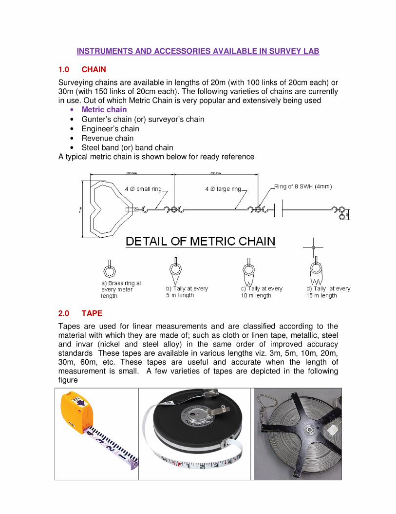
Surveying chains are available in lengths of 20m (with 100 links of 20cm each) or 30m (with 150 links of 20cm each). The following varieties of chains are currently in use. Out of which Metric Chain is very popular and extensively being used
• Metric chain
• Gunter’s chain (or) surveyor’s chain
• Engineer’s chain
• Revenue chain
• Steel band (or) band chain A typical metric chain is shown below for ready reference
2.0 TAPE
Tapes are used for linear measurements and are classified according to the material with which they are made of; such as cloth or linen tape, metallic, steel and invar (nickel and steel alloy) in the same order of improved accuracy standards These tapes are available in various lengths viz. 3m, 5m, 10m, 20m, 30m, 60m, etc. These tapes are useful and accurate when the length of measurement is small. A few varieties of tapes are depicted in the following figure
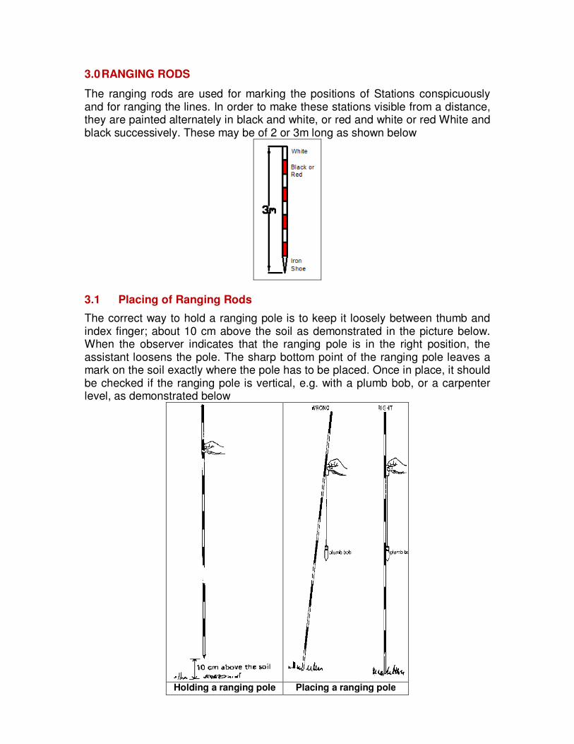
3.0 RANGING RODS
The ranging rods are used for marking the positions of Stations conspicuously and for ranging the lines. In order to make these stations visible from a distance, they are painted alternately in black and white, or red and white or red White and black successively. These may be of 2 or 3m long as shown below
3.1 Placing of Ranging Rods
The correct way to hold a ranging pole is to keep it loosely between thumb and index finger; about 10 cm above the soil as demonstrated in the picture below. When the observer indicates that the ranging pole is in the right position, the assistant loosens the pole. The sharp bottom point of the ranging pole leaves a mark on the soil exactly where the pole has to be placed. Once in place, it should be checked if the ranging pole is vertical, e.g. with a plumb bob, or a carpenter level, as demonstrated below
Holding a ranging pole Placing a ranging pole
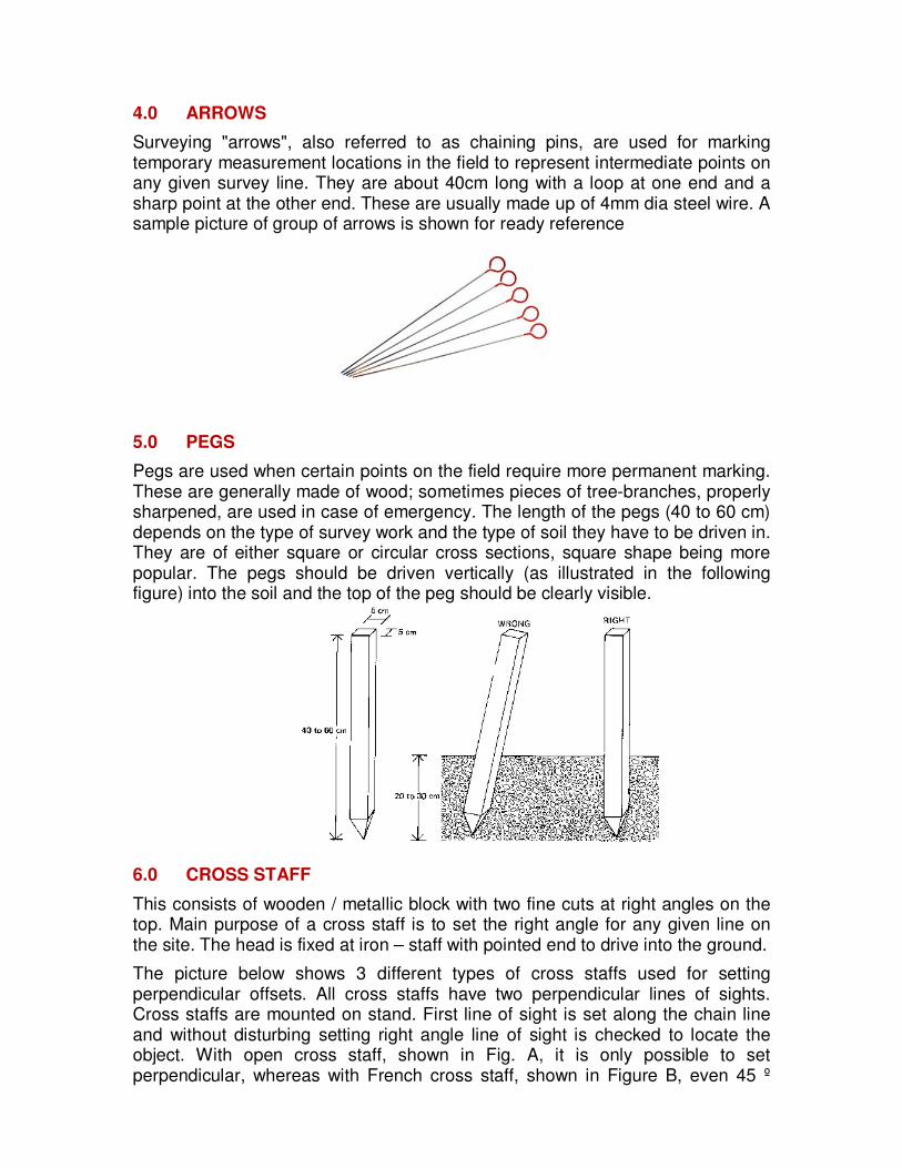
4.0 ARROWS
Surveying "arrows", also referred to as chaining pins, are used for marking temporary measurement locations in the field to represent intermediate points on any given survey line. They are about 40cm long with a loop at one end and a sharp point at the other end. These are usually made up of 4mm dia steel wire. A sample picture of group of arrows is shown for ready reference
5.0 PEGS
Pegs are used when certain points on the field require more permanent marking. These are generally made of wood; sometimes pieces of tree-branches, properly sharpened, are used in case of emergency. The length of the pegs (40 to 60 cm) depends on the type of survey work and the type of soil they have to be driven in. They are of either square or circular cross sections, square shape being more popular. The pegs should be driven vertically (as illustrated in the following figure) into the soil and the top of the peg should be clearly visible.
6.0 CROSS STAFF
This consists of wooden / metallic block with two fine cuts at right angles on the top. Main purpose of a cross staff is to set the right angle for any given line on the site. The head is fixed at iron – staff with pointed end to drive into the ground.
The picture below shows 3 different types of cross staffs used for setting perpendicular offsets. All cross staffs have two perpendicular lines of sights. Cross staffs are mounted on stand. First line of sight is set along the chain line and without disturbing setting right angle line of sight is checked to locate the object. With open cross staff, shown in Fig. A, it is only possible to set perpendicular, whereas with French cross staff, shown in Figure B, even 45 º
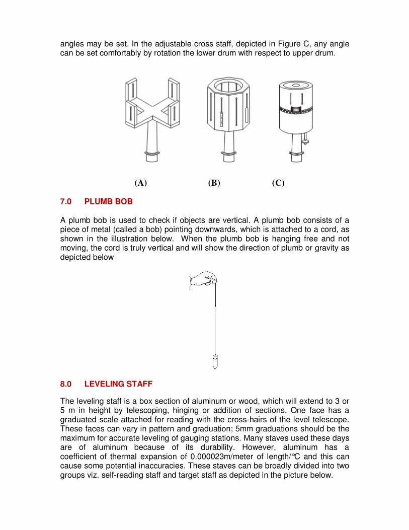
angles may be set. In the adjustable cross staff, depicted in Figure C, any angle can be set comfortably by rotation the lower drum with respect to upper drum.
(A) (B) (C)
7.0 PLUMB BOB
A plumb bob is used to check if objects are vertical. A plumb bob consists of a piece of metal (called a bob) pointing downwards, which is attached to a cord, as shown in the illustration below. When the plumb bob is hanging free and not moving, the cord is truly vertical and will show the direction of plumb or gravity as depicted below
8.0 LEVELING STAFF
The leveling staff is a box section of aluminum or wood, which will extend to 3 or 5 m in height by telescoping, hinging or addition of sections. One face has a graduated scale attached for reading with the cross-hairs of the level telescope. These faces can vary in pattern and graduation; 5mm graduations should be the maximum for accurate leveling of gauging stations. Many staves used these days are of aluminum because of its durability. However, aluminum has a coefficient of thermal expansion of 0.000023m/meter of length/°C and this can cause some potential inaccuracies. These staves can be broadly divided into two groups viz. self-reading staff and target staff as depicted in the picture below.
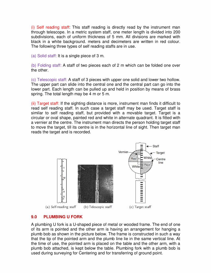
(i) Self reading staff: This staff reading is directly read by the instrument man through telescope. In a metric system staff, one meter length is divided into 200 subdivisions, each of uniform thickness of 5 mm. All divisions are marked with black in a white background. meters and decimeters are written in red colour. The following three types of self reading staffs are in use. (a) Solid staff: It is a single piece of 3 m. (b) Folding staff: A staff of two pieces each of 2 m which can be folded one over the other. (c) Telescopic staff: A staff of 3 pieces with upper one solid and lower two hollow. The upper part can slide into the central one and the central part can go into the lower part. Each length can be pulled up and held in position by means of brass spring. The total length may be 4 m or 5 m. (ii) Target staff: If the sighting distance is more, instrument man finds it difficult to read self reading staff. In such case a target staff may be used. Target staff is similar to self reading staff, but provided with a movable target. Target is a circular or oval shape, painted red and white in alternate quadrant. It is fitted with a vernier at the centre. The instrument man directs the person holding target staff to move the target, till its centre is in the horizontal line of sight. Then target man reads the target and is recorded.
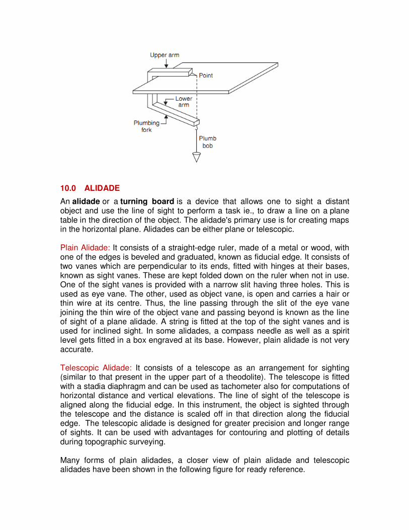
9.0 PLUMBING U FORK
A plumbing U fork is a U-shaped piece of metal or wooded frame. The end of one of its arm is pointed and the other arm is having an arrangement for hanging a plumb bob as shown in the picture below. The frame is constructed in such a way that the tip of the pointed arm and the plumb line lie in the same vertical line. At the time of use, the pointed arm is placed on the table and the other arm, with a plumb bob attached, is kept below the table. Plumbing fork with a plumb bob is used during surveying for Centering and for transferring of ground point.
10.0 ALIDADE
An alidade or a turning board is a device that allows one to sight a distant object and use the line of sight to perform a task ie., to draw a line on a plane table in the direction of the object. The alidade's primary use is for creating maps in the horizontal plane. Alidades can be either plane or telescopic. Plain Alidade: It consists of a straight-edge ruler, made of a metal or wood, with one of the edges is beveled and graduated, known as fiducial edge. It consists of two vanes which are perpendicular to its ends, fitted with hinges at their bases, known as sight vanes. These are kept folded down on the ruler when not in use. One of the sight vanes is provided with a narrow slit having three holes. This is used as eye vane. The other, used as object vane, is open and carries a hair or thin wire at its centre. Thus, the line passing through the slit of the eye vane joining the thin wire of the object vane and passing beyond is known as the line of sight of a plane alidade. A string is fitted at the top of the sight vanes and is used for inclined sight. In some alidades, a compass needle as well as a spirit level gets fitted in a box engraved at its base. However, plain alidade is not very accurate. Telescopic Alidade: It consists of a telescope as an arrangement for sighting (similar to that present in the upper part of a theodolite). The telescope is fitted with a stadia diaphragm and can be used as tachometer also for computations of horizontal distance and vertical elevations. The line of sight of the telescope is aligned along the fiducial edge. In this instrument, the object is sighted through the telescope and the distance is scaled off in that direction along the fiducial edge. The telescopic alidade is designed for greater precision and longer range of sights. It can be used with advantages for contouring and plotting of details during topographic surveying. Many forms of plain alidades, a closer view of plain alidade and telescopic alidades have been shown in the following figure for ready reference.
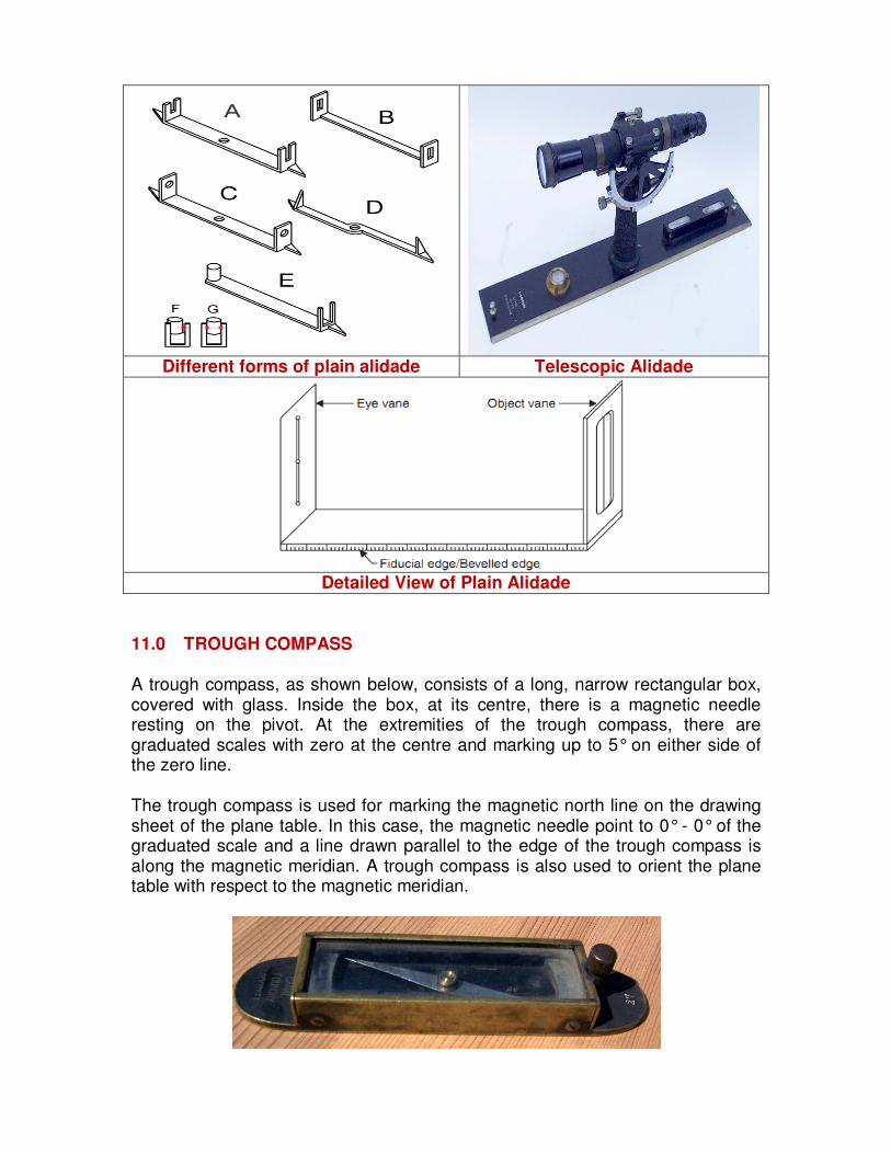
Different forms of plain alidade Telescopic Alidade
Detailed View of Plain Alidade
11.0 TROUGH COMPASS
A trough compass, as shown below, consists of a long, narrow rectangular box, covered with glass. Inside the box, at its centre, there is a magnetic needle resting on the pivot. At the extremities of the trough compass, there are graduated scales with zero at the centre and marking up to 5° on either side of the zero line.
The trough compass is used for marking the magnetic north line on the drawing sheet of the plane table. In this case, the magnetic needle point to 0° - 0° of the graduated scale and a line drawn parallel to the edge of the trough compass is along the magnetic meridian. A trough compass is also used to orient the plane table with respect to the magnetic meridian.
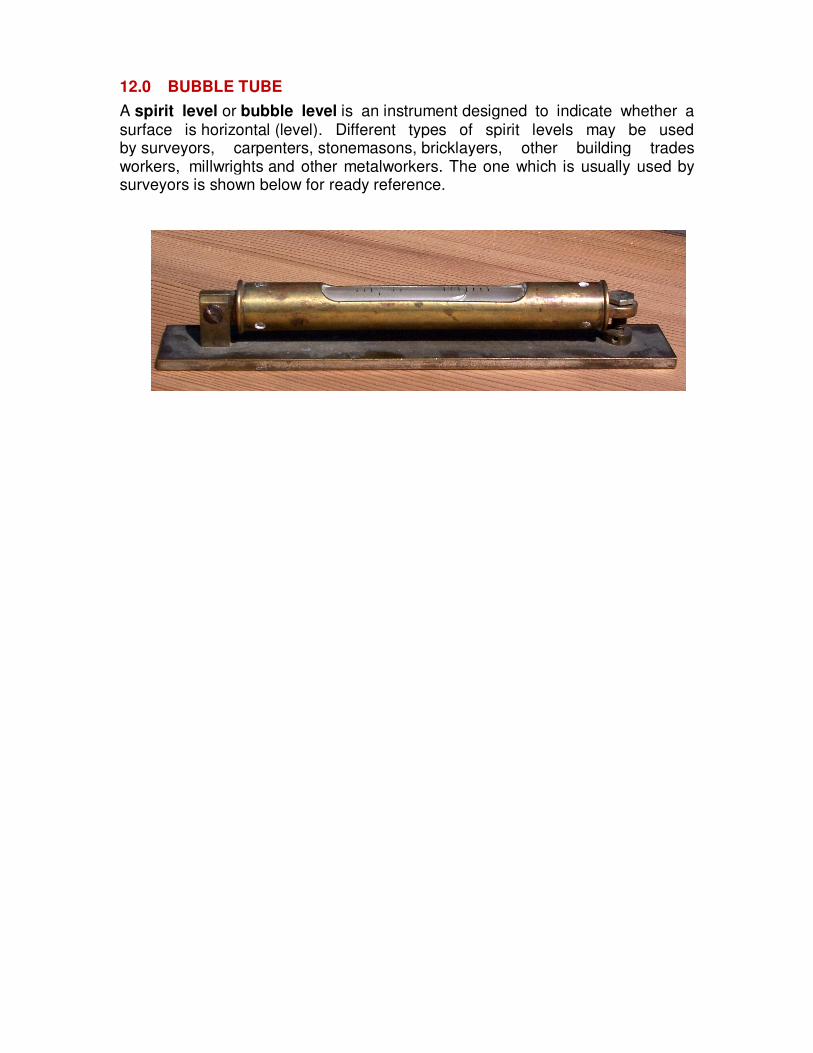
12.0 BUBBLE TUBE
A spirit level or bubble level is an instrument designed to indicate whether a surface is horizontal (level). Different types of spirit levels may be used by surveyors, carpenters, stonemasons, bricklayers, other building trades workers, millwrights and other metalworkers. The one which is usually used by surveyors is shown below for ready reference.
SOME IMPROTANT PROCESSES HANDLED IN SURVEY FIELD
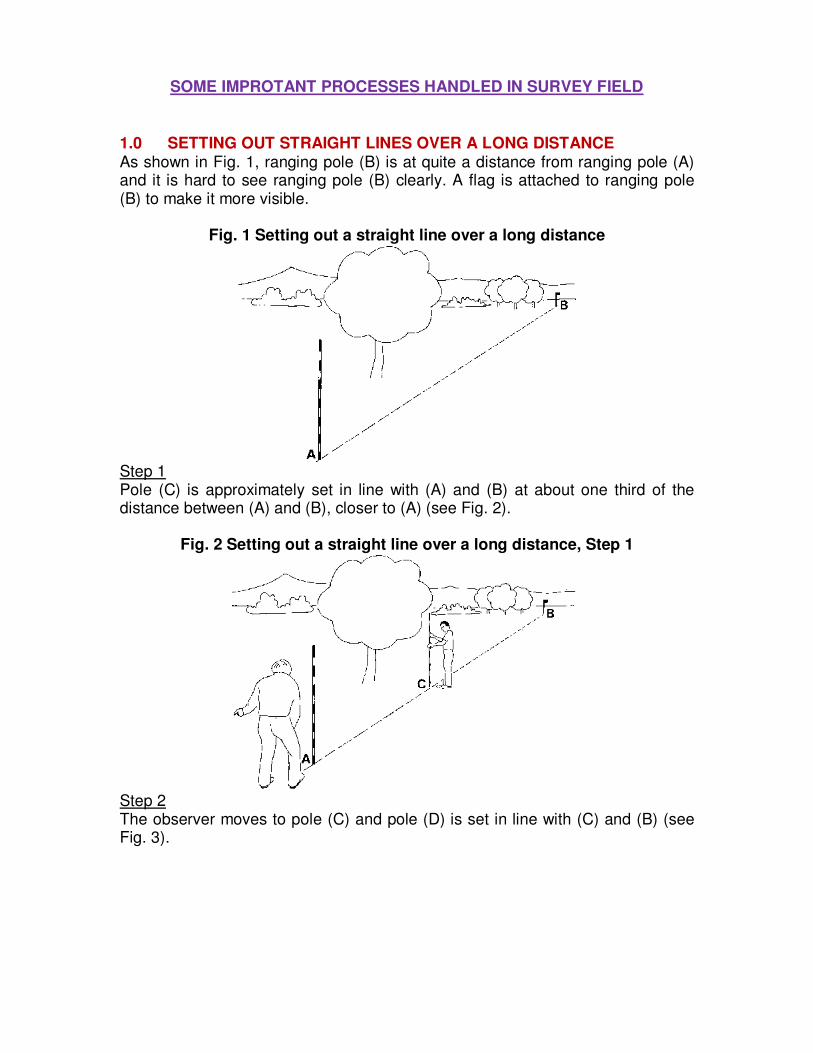
1.0 SETTING OUT STRAIGHT LINES OVER A LONG DISTANCE As shown in Fig. 1, ranging pole (B) is at quite a distance from ranging pole (A) and it is hard to see ranging pole (B) clearly. A flag is attached to ranging pole (B) to make it more visible.
Fig. 1 Setting out a straight line over a long distance
Step 1 Pole (C) is approximately set in line with (A) and (B) at about one third of the distance between (A) and (B), closer to (A) (see Fig. 2).
Fig. 2 Setting out a straight line over a long distance, Step 1
Step 2 The observer moves to pole (C) and pole (D) is set in line with (C) and (B) (see Fig. 3).
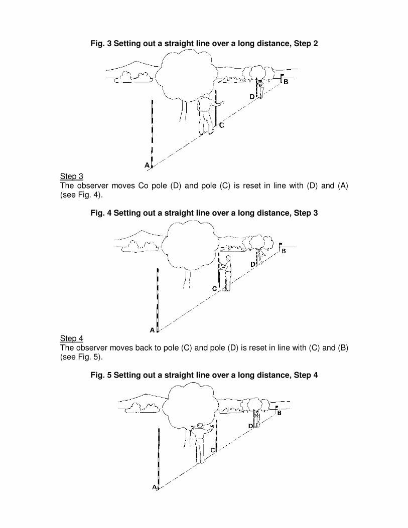
Fig. 3 Setting out a straight line over a long distance, Step 2
Step 3 The observer moves Co pole (D) and pole (C) is reset in line with (D) and (A) (see Fig. 4).
Fig. 4 Setting out a straight line over a long distance, Step 3
Step 4 The observer moves back to pole (C) and pole (D) is reset in line with (C) and (B) (see Fig. 5).
Fig. 5 Setting out a straight line over a long distance, Step 4
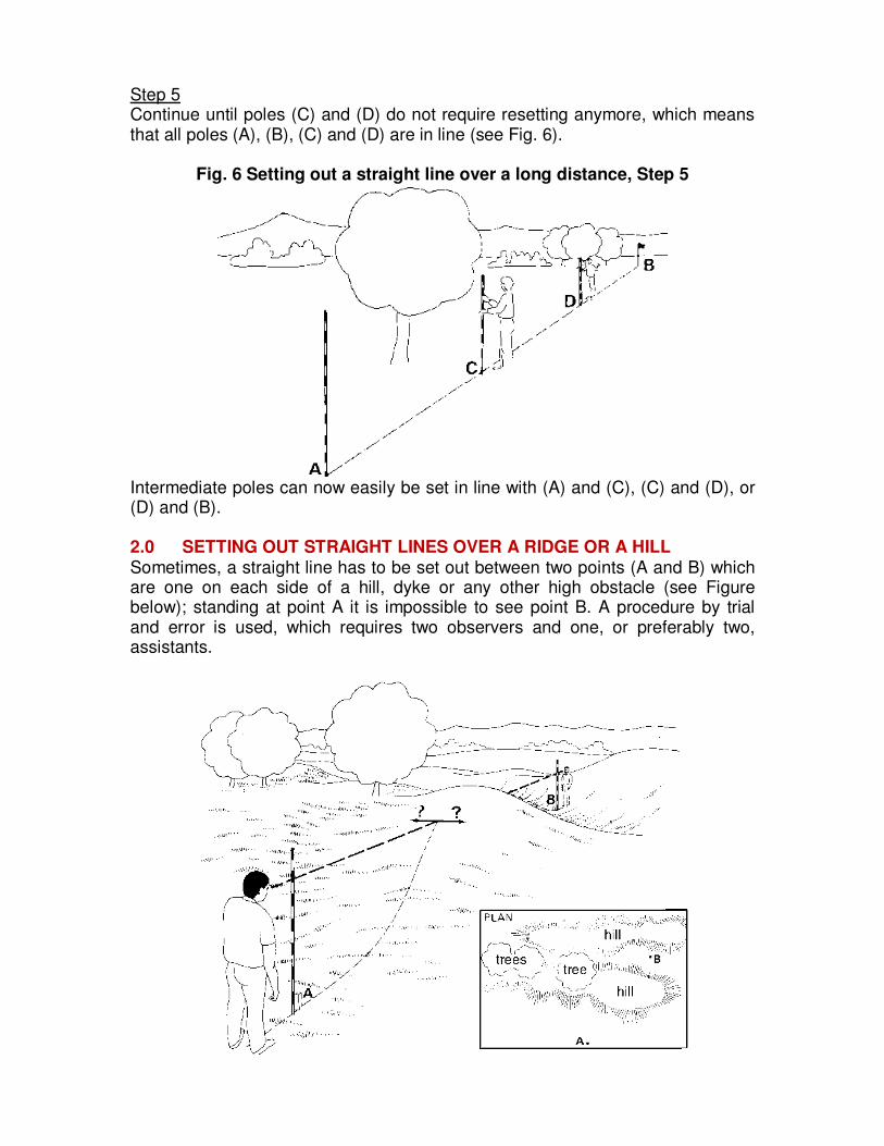
Step 5 Continue until poles (C) and (D) do not require resetting anymore, which means that all poles (A), (B), (C) and (D) are in line (see Fig. 6).
Fig. 6 Setting out a straight line over a long distance, Step 5
Intermediate poles can now easily be set in line with (A) and (C), (C) and (D), or (D) and (B). 2.0 SETTING OUT STRAIGHT LINES OVER A RIDGE OR A HILL Sometimes, a straight line has to be set out between two points (A and B) which are one on each side of a hill, dyke or any other high obstacle (see Figure below); standing at point A it is impossible to see point B. A procedure by trial and error is used, which requires two observers and one, or preferably two, assistants.
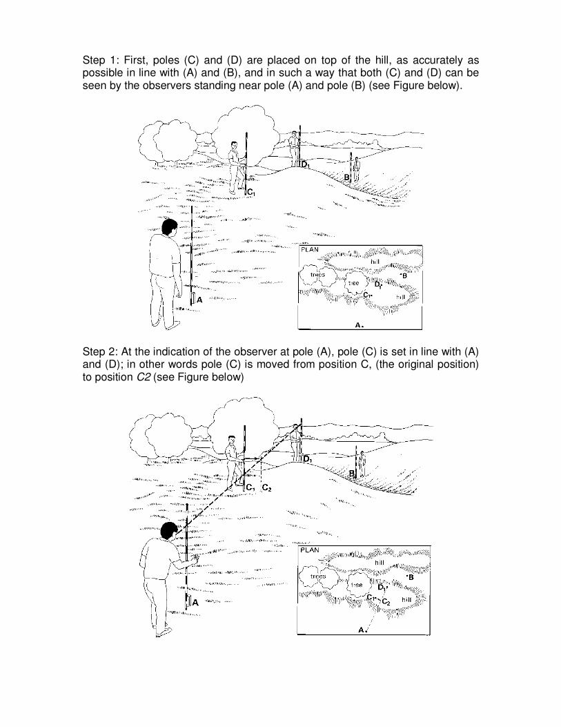
Step 1: First, poles (C) and (D) are placed on top of the hill, as accurately as possible in line with (A) and (B), and in such a way that both (C) and (D) can be seen by the observers standing near pole (A) and pole (B) (see Figure below).
Step 2: At the indication of the observer at pole (A), pole (C) is set in line with (A) and (D); in other words pole (C) is moved from position C, (the original position) to position C2 (see Figure below)
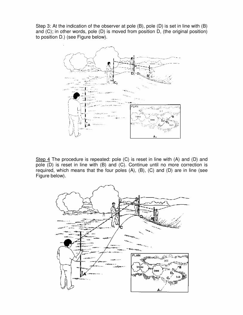
Step 3: At the indication of the observer at pole (B), pole (D) is set in line with (B) and (C); in other words, pole (D) is moved from position D, (the original position) to position D.) (see Figure below).
Step 4 The procedure is repeated: pole (C) is reset in line with (A) and (D) and pole (D) is reset in line with (B) and (C). Continue until no more correction is required, which means that the four poles (A), (B), (C) and (D) are in line (see Figure below).
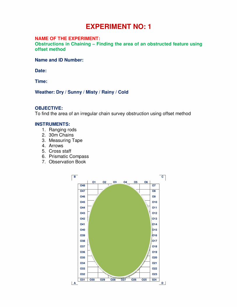
EXPERIMENT NO: 1 NAME OF THE EXPERIMENT: Obstructions in Chaining – Finding the area of an obstructed feature using offset method Name and ID Number:
Date:
Time:
Weather: Dry / Sunny / Misty / Rainy / Cold
OBJECTIVE: To find the area of an irregular chain survey obstruction using offset method INSTRUMENTS:
1. Ranging rods 2. 30m Chains 3. Measuring Tape 4. Arrows 5. Cross staff 6. Prismatic Compass 7. Observation Book
B C
O1 O2 O3 O4 O5 O6
O48 O7
O47 O8
O46 O9
O45 O10
O44 O11
O43 O12
O42 O13
O41 O14
O40 O15
O39 O16
O38 O17
O37 O18
O36 O19
O35 O20
O34 O21
O33 O22
O32 O23
O31 O30 O29 O28 O27 O26 O25 024
A D
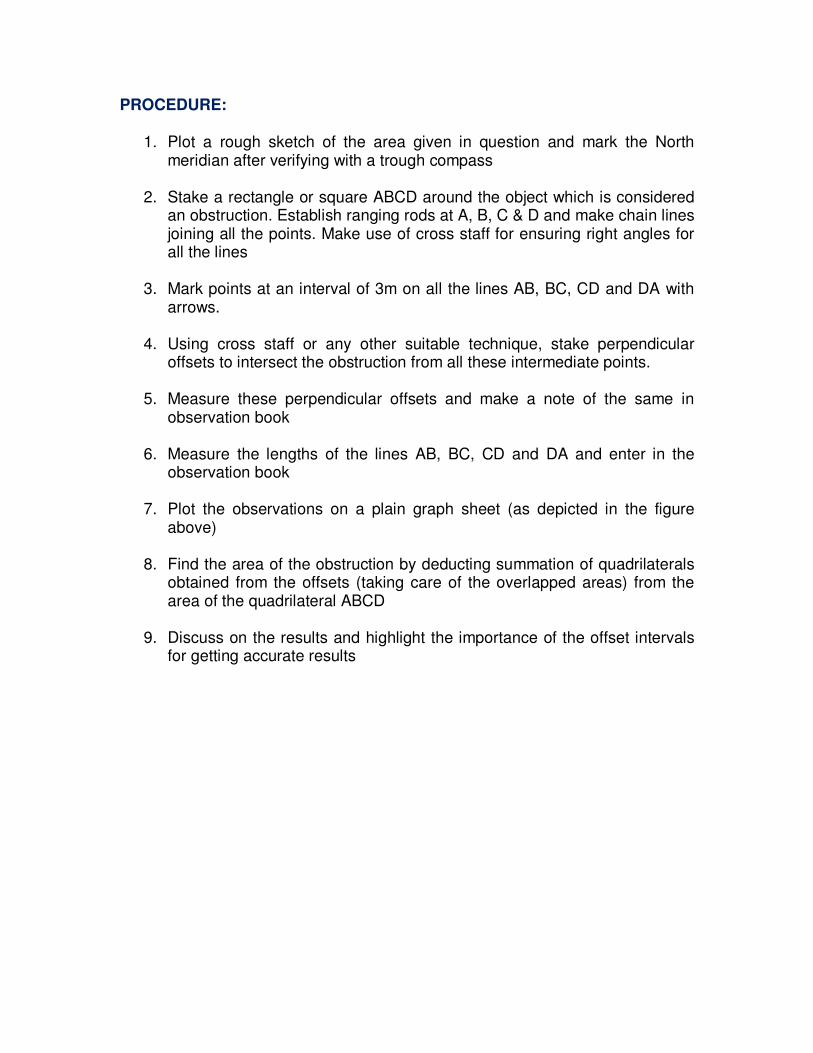
PROCEDURE:
1. Plot a rough sketch of the area given in question and mark the North meridian after verifying with a trough compass
2. Stake a rectangle or square ABCD around the object which is considered an obstruction. Establish ranging rods at A, B, C & D and make chain lines joining all the points. Make use of cross staff for ensuring right angles for all the lines
3. Mark points at an interval of 3m on all the lines AB, BC, CD and DA with arrows.
4. Using cross staff or any other suitable technique, stake perpendicular offsets to intersect the obstruction from all these intermediate points.
5. Measure these perpendicular offsets and make a note of the same in observation book
6. Measure the lengths of the lines AB, BC, CD and DA and enter in the observation book
7. Plot the observations on a plain graph sheet (as depicted in the figure above)
8. Find the area of the obstruction by deducting summation of quadrilaterals obtained from the offsets (taking care of the overlapped areas) from the area of the quadrilateral ABCD
9. Discuss on the results and highlight the importance of the offset intervals for getting accurate results
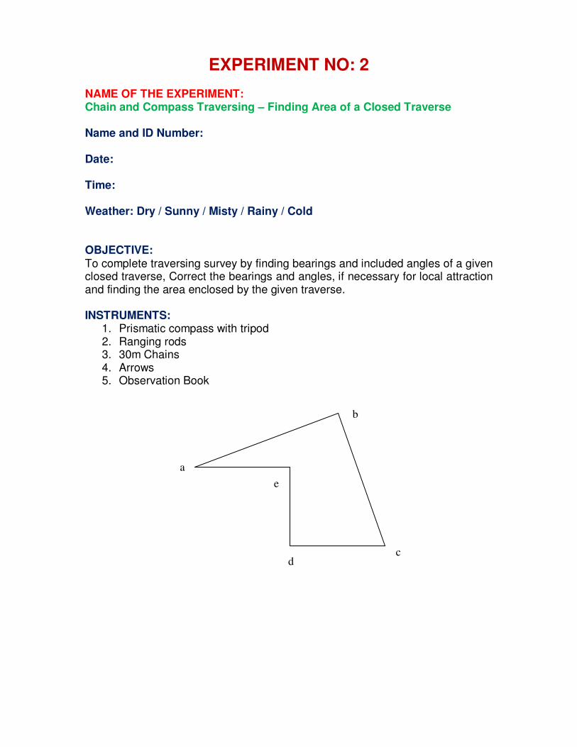
EXPERIMENT NO: 2 NAME OF THE EXPERIMENT: Chain and Compass Traversing – Finding Area of a Closed Traverse Name and ID Number:
Date:
Time:
Weather: Dry / Sunny / Misty / Rainy / Cold
OBJECTIVE: To complete traversing survey by finding bearings and included angles of a given closed traverse, Correct the bearings and angles, if necessary for local attraction and finding the area enclosed by the given traverse. INSTRUMENTS:
1. Prismatic compass with tripod 2. Ranging rods 3. 30m Chains 4. Arrows 5. Observation Book
a
b
e
d c
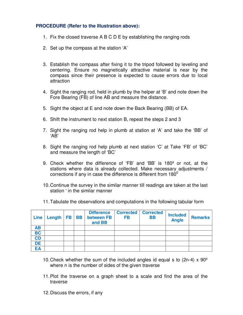
PROCEDURE (Refer to the Illustration above):
1. Fix the closed traverse A B C D E by establishing the ranging rods
2. Set up the compass at the station ‘A’ 3. Establish the compass after fixing it to the tripod followed by leveling and
centering. Ensure no magnetically attractive material is near by the compass since their presence is expected to cause errors due to local attraction
4. Sight the ranging rod, held in plumb by the helper at ‘B’ and note down the Fore Bearing (FB) of line AB and measure the distance.
5. Sight the object at E and note down the Back Bearing (BB) of EA.
6. Shift the instrument to next station B, repeat the steps 2 and 3
7. Sight the ranging rod help in plumb at station at ‘A’ and take the ‘BB’ of ‘AB’
8. Sight the ranging rod help plumb at next station ‘C’ at Take ‘FB’ of ‘BC’ and measure the length of ‘BC’
9. Check whether the difference of ‘FB’ and ‘BB’ is 180º or not, at the stations where data is already collected. Make necessary adjustments / corrections if any in case the difference is different from 1800
10. Continue the survey in the similar manner till readings are taken at the last station ‘ in the similar manner
11. Tabulate the observations and computations in the following tabular form
Line Length FB BB Difference
between FB and BB
Corrected FB
Corrected BB
Included Angle
Remarks
AB BC CD DE EA
10. Check whether the sum of the included angles id equal s to (2n-4) x 90º
where n is the number of sides of the given traverse
11. Plot the traverse on a graph sheet to a scale and find the area of the traverse
12. Discuss the errors, if any
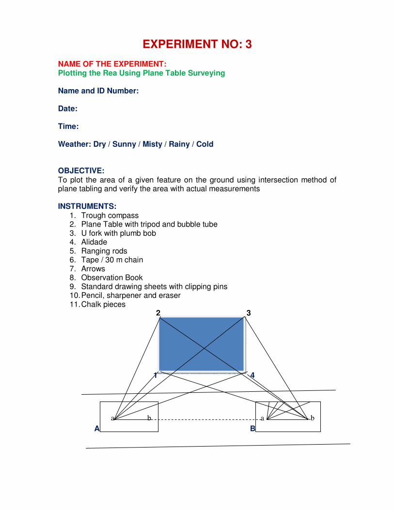
EXPERIMENT NO: 3 NAME OF THE EXPERIMENT: Plotting the Rea Using Plane Table Surveying Name and ID Number:
Date:
Time:
Weather: Dry / Sunny / Misty / Rainy / Cold
OBJECTIVE: To plot the area of a given feature on the ground using intersection method of plane tabling and verify the area with actual measurements INSTRUMENTS:
1. Trough compass 2. Plane Table with tripod and bubble tube 3. U fork with plumb bob 4. Alidade 5. Ranging rods 6. Tape / 30 m chain 7. Arrows 8. Observation Book 9. Standard drawing sheets with clipping pins 10. Pencil, sharpener and eraser 11. Chalk pieces
2 3 1 4
A B
a b
a b
PROCEDURE:
1. The ground feature represented by 1 2 3 4 is given to be plotted on the plane table using method of intersection
2. Set up the plane table at station A which is chosen at convenient location to have non overlapping rays to be plotted for all the end points of the chosen ground feature
3. Using a trough compass, show the Magnetic North meridian on one of top corners of the sheets using the standard arrow mark
4. Level the table with a bubble tube, transfer the point on the ground on to the table using U fork with a plumbing bob. Marks this point as ‘a’ and the ground point as ‘A’
5. Pivoting about the point ‘a’ with the fiducial edge of the alidade, orient the alidade to see the ranging rod held at point ‘1’ of the ground feature as depicted in the picture presented above, draw a ray from ‘a’ in the direction of point ‘1’
6. Direct the helper to move to the point ‘2’ and hold the ranging rod plumb. Once again, pivoting about ‘a’, draw a ray after targeting the point ‘2’ on the ground. This process continues till all the rays are plotted on the sheet from point ‘A’
7. Chose a convenient point ‘B’ on the ground with the same condition being followed as for the point ‘A’. Make sure that the line AB is approximately parallel to one of the sides of the feature being attempted. This ensures good accuracy in finding the area. With the alidade, draw a line AB. Measure AB with a tape or chain and represent ‘ab’ on the sheet with some chosen convenient scale.
8. Shift the station to point ‘B’, holding a ranging rod at ‘A’, with the help of alidade placed with its fiducial edge on line ab on the sheet, orient the table to target the station ‘A’ there by ensuring proper orientation of the table. IN addition, the point ‘B’ on the ground also shall be exactly pointing to the point B on the ground. While doing all these, ensure that the table is level too. Once leveling, centering and orientation is matching perfectly, draw rays from ‘b’ to points 1, 2, 3 & 4 to intersect the corresponding rays drawn earlier from station ‘A’
9. Mark out the intersecting points and join them with straight lines. This represents the ground feature in question with the scale with which the line ‘ab’ is plotted
10. Now find the area on the sheet and convert that value in to the real time value by multiplying with the area scale factor. Verify this area with the actual area being measured and found in the filed.
11. The area obtained from Plane Table should not vary from the actual area beyond 5% either way
12. Comment on the error and accuracy, if necessary
EXPERIMENT NO: 4 NAME OF THE EXPERIMENT: Profile Leveling and Volume of Earthwork Name and ID Number:
Date:
Time:
Weather: Dry / Sunny / Misty / Rainy / Cold
OBJECTIVE: To perform fly leveling (profile leveling) on a given stretch of highway to find LS and CS and to calculate the volume of earth quake required to achieve the defined gradient on the stretch INSTRUMENTS:
1. Auto Level or Dumpy Level with a tripod arrangement 2. Leveling staff (foldable or telescopic or self reading) 3. Trough compass 4. Ranging rods 5. 30m Chains 6. Arrows 7. Observation Book
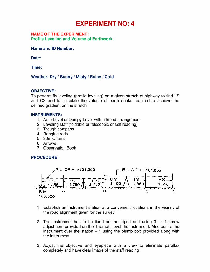
PROCEDURE:
1. Establish an instrument station at a convenient locations in the vicinity of
the road alignment given for the survey
2. The instrument has to be fixed on the tripod and using 3 or 4 screw adjustment provided on the Tribrach, level the instrument. Also centre the instrument over the station – 1 using the plumb bob provided along with the instrument.
3. Adjust the objective and eyepiece with a view to eliminate parallax completely and have clear image of the staff reading
4. Take a back sight on to the chosen bench mark (temporary or permanent
depending upon the availability)
5. Mark points on the proposed road alignment along the centre line at a given interval for longitudinal section (LS) and also on either side of the alignment for cross sections (CS) at the same intervals.
6. Take levels at all the marked points for LS and CS by holding the leveling staff plumb at all the points and record separately for LS and CS.
7. Record the readings after the back sight as Intermediate Sights and the final reading before the instruments needs a change of location as Fore Sight
8. Once the station ceases to be visible from the first instrument station, take the foresight on the final point from the first instrument station and then change the instrument to station 2 from where the remaining points are visible.
9. After centering and leveling at station, as done for station 1, take a back sight on the last point where the foresight is taken from station 1. This is to ensure the continuity of the leveling survey
10. Then proceed further with Intermediate sights and finally the foresight.
11. In case of necessity, keep changing the instrument stations and continue the survey process
12. Enter the readings in a typical proforma as shown below and use either height of collimation procedure or rise and fall procedure to get the longitudinal and cross sectional profiles.
Back Sight
Intermediate Sight
Fore Sight
Height of Instrument
Rise Fall RL Remarks
13. Using the standard procedures, calculate the earth work required to
achieve a given gradient t line and show the volumes of cutting and filling separately. Use Graphs to plot LS and CS (Excel Sheets can be used)
14. Discuss the importance of balanced earth work and verify whether the case study carried out by you is balanced or not.
EXPERIMENT NO: 5 NAME OF THE EXPERIMENT: Contour Surveying by Square Grids Name and ID Number:
Date:
Time:
Weather: Dry / Sunny / Misty / Rainy / Cold
OBJECTIVE: To plot the contours for a given area with a given contour interval INSTRUMENTS:
1. Auto Level or Dumpy Level with a tripod arrangement 2. Leveling staff (foldable or telescopic or self reading) 3. Trough compass 4. Cross Staff 5. Ranging rods 6. 30m Chains 7. Arrows 8. Observation Book
PROCEDURE:
1. Stake as big a square as possible in the area where the contours are
supposed to be plotted (for the class room exercise, a 15m x 15m square is recommended)
2. Make smaller square grids ( smaller the grid size, better the accuracy) and choose the grid size based on the need, time & man power availability as demonstrated in the figure given below
3. Fix the leveling instrument on the tripod and using 3 or 4 screw adjustment provided on the Tribrach, level the instrument. Also centre the instrument over a stable and level ground using the plumb bob provided along with the instrument.
4. Adjust the objective and eyepiece with a view to eliminate parallax completely and have clear image of the staff reading
5. Take a back sight on to the chosen bench mark (temporary or permanent depending upon the availability)
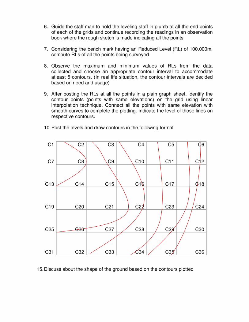
6. Guide the staff man to hold the leveling staff in plumb at all the end points of each of the grids and continue recording the readings in an observation book where the rough sketch is made indicating all the points
7. Considering the bench mark having an Reduced Level (RL) of 100.000m, compute RLs of all the points being surveyed.
8. Observe the maximum and minimum values of RLs from the data collected and choose an appropriate contour interval to accommodate atleast 5 contours. (In real life situation, the contour intervals are decided based on need and usage)
9. After posting the RLs at all the points in a plain graph sheet, identify the contour points (points with same elevations) on the grid using linear interpolation technique. Connect all the points with same elevation with smooth curves to complete the plotting. Indicate the level of those lines on respective contours.
10. Post the levels and draw contours in the following format
C1
C7
C2
C8
C3
C9
C4
C10
C5
C11
C6
C12
C13 C14 C15 C16 C17 C18
C19 C20 C21 C22 C23 C24
C25 C26 C27 C28 C29 C30
C31 C32 C33 C34 C35 C36
15. Discuss about the shape of the ground based on the contours plotted