surveying made easy - leica geosystemsw3.leica-geosystems.com/.../brochures/surveying_en.pdf ·...
TRANSCRIPT

Surveying Made Easy

2 | Introduction
Introduction
Dear students, teachers,and everyone interested in surveying, In recent years, the development of modern and easy to use measuring instruments has contributed to the use of such instruments by more and more users in many fields. The following booklet provides information on the basics of surveying measurement, the most commonly used instruments and the most important everyday tasks employed by surveyors and other users.
Trainees, students, and professionals in the fields of surveying, civil engineering, architecture, and many other fields can find answers to their questions:
What are the characteristics of survey instruments?What do I need to take care of when measuring with a level or total station?What is the effect of instrument error and how to recognize, determine and eliminate such errors?How do I perform simple measurement tasks?
Many survey tasks – the calculation of areas or volumes, the collection, checking, and staking of points or the transfer of heights – can be performed automatically using built-in application programs. In addition to total station and level measurement, surveying with GNSS satellite systems will be briefly discussed.
With nearly 200 years of experience in developing and manufacturing surveying instruments, Leica Geosystems provides a comprehensive range of innovative products and solutions for surveying tasks. To view the entire product portfolio offered by Leica Geosystems, please visit www.leica-geosystems.com.
I wish you every success with your training, study, and work and hope that you find this booklet useful. With best regards,
Johannes Schwarz,President Division GeomaticsLeica Geosystems AG
Contents | 3
The Level 4
Preparing to Measure 5Setting up the Level 5Levelling-up the Instrument 5Preparing the Instrument for Parallax-free Measurements 6Inspecting the Line of Sight (two-peg test) 7
Measuring with the Level 8Height Difference between two Points 8Measuring Distances Optically with the Level 9Line Levelling 10Staking out Point Heights 11Longitudinal and Transverse Profiles 12
Digital level and Rotating Laser 13The Digital Level 13The Rotating Laser 13
The Total Station 14
Overview 15Reflectorless Distance Measurement 15Automatic Target Aiming 15Coordinates 16Measuring Angles 17
Instrument Errors 18Instrument Errors of a Total Station 18Checking the EDM of a Total Station 20
Setup to Measure 21Setup over a Known Point (enter station coordinates and orientation) 21Resection (calculate station coordinates and orientation) 22
Simple Surveying Tasks 23Extrapolating a Straight Line 23Polar Stake-out of a Point 23Measuring Slopes 24Plumbing Up or Down 25
Application Programs 26Surveys (polar method) 26Staking Out 27Reference Line 28Volume Valculation 28Area Calculation 29Remote Heights 30Tie Distances 31Staking out Profile Boards 32
Surveying with GNSS (GPS & Glonass) 33GNSS Reference Stations 34
Contents

4 | The Level
The Level
A level is essentially a telescope that rotates around a ver-tical axis. It is used to create a horizontal line of sight so that height differences can be determined and stakeouts can be performed.
Leica Geosystems levels are also equipped with a horizon-tal circle that is very useful for setting out right angles, e.g. during the recording of transverse profiles. In addi-tion, these levels can be used to determine distances opti-cally with an accuracy of 0.1 to 0.3 m (4 – 12 in).
Preparing to Measure | 5
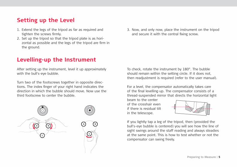
Setting up the Level
1. Extend the legs of the tripod as far as required and tighten the screws firmly.
2. Set up the tripod so that the tripod plate is as hori-zontal as possible and the legs of the tripod are firm in the ground.
3. Now, and only now, place the instrument on the tripod and secure it with the central fixing screw.
Levelling-up the Instrument
After setting up the instrument, level it up approximately with the bull’s-eye bubble.
Turn two of the foot screws together in opposite direc-tions. The index finger of your right hand indicates the direction in which the bubble should move. Now use the third footscrew to center the bubble.
To check, rotate the instru ment by 180°. The bubble should remain within the setting circle. If it does not, then readjustment is required (refer to the user manual).
For a level, the compen sator automatically takes care of the final levelling-up. The compensator consists of a thread-suspended mirror that directs the horizontal light beam to the center of the crosshair even if there is residual tilt in the tele scope.
If you lightly tap a leg of the tripod, then (pro vided the bull’s-eye bubble is centered) you will see how the line of sight swings around the staff reading and always steadies at the same point. This is how to test whether or not the compensator can swing freely.
6 | Preparing to Measure
Preparing the Instrument for Parallax-free Measurements
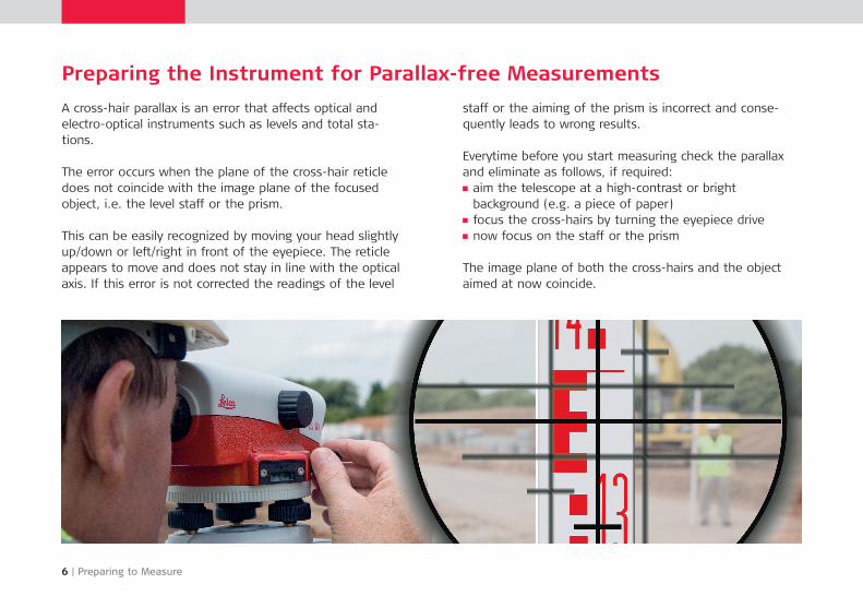
A cross-hair parallax is an error that affects optical and electro-optical instruments such as levels and total sta-tions.
The error occurs when the plane of the cross-hair reticle does not coincide with the image plane of the focused object, i.e. the level staff or the prism.
This can be easily recognized by moving your head slightly up/down or left/right in front of the eyepiece. The reticle appears to move and does not stay in line with the optical axis. If this error is not corrected the readings of the level
staff or the aiming of the prism is incorrect and conse-quently leads to wrong results.
Everytime before you start measuring check the parallax and eliminate as follows, if required:
aim the telescope at a high-contrast or bright background (e.g. a piece of paper)focus the cross-hairs by turning the eyepiece drivenow focus on the staff or the prism
The image plane of both the cross-hairs and the object aimed at now coincide.
Preparing to Measure | 7
Inspecting the Line of Sight (two-peg test)
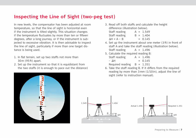
In new levels, the com pensator has been adjusted at room temperature, so that the line of sight is hori zontal even if the instru ment is tilted slightly. This situation changes if the temperature fluctuates by more than ten or fifteen degrees, after a long jour ney, or if the instrument is sub-jected to excessive vibra tion. It is then advisable to inspect the line of sight, particularly if more than one target dis-tance is being used.
1. In flat terrain, set up two staffs not more than 30 m (95 ft) apart.
2. Set up the instrument so that it is equidistant from the two staffs (it is enough to pace out the distance)
3. Read off both staffs and calculate the height difference (illustration below).
Staff reading A = 1.549 Staff reading B = 1.404 iH = A – B = 0.1454. Set up the instrument about one meter (3 ft) in front of
staff A and take the staff reading (illustration below). Staff reading A = 1.4965. Calculate the required reading B: Staff reading A = 1.496 – iH = 0.145 Required reading B = 1.3516. Take the staff reading B. If it differs from the required
reading by more than 3 mm (1/10 in), adjust the line of sight (refer to instruction manual).
1.549 1.404Actual 1.496 Required 1.351
8 | Measuring with the Level
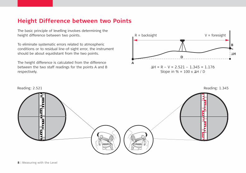
Height Difference between two Points
The basic principle of levelling involves determining the height difference between two points.
To eliminate systematic errors related to atmospheric conditions or to residual line-of-sight error, the instrument should be about equidistant from the two points.
The height difference is calculated from the difference between the two staff readings for the points A and B respectively.
iH = R – V = 2.521 – 1.345 = 1.176Slope in % = 100 x iH / D
Reading: 2.521 Reading: 1.345
A
B
iH D
R = backsight V = foresight

Measuring with the Level | 9
Measuring Distances Optically with the Level
The reticle has two stadia lines arranged symmetrically to the cross-hairs. Their spacing is such that the distance can be derived by multiplying the corresponding staff section by 100.
Accuracy of the distance measurement: 10 – 30 cm (4 – 12 in)
Example:Reading on upper stadia line B = 1.205Reading on lower stadia line A = 0.996Staff section I = B – A = 0.209
Distance = 100 x I = 20.9 mB
A
D
10 | Measuring with the Level
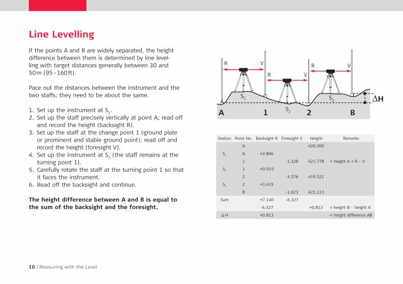
Line Levelling
If the points A and B are widely separated, the height difference between them is determined by line level- ling with target distances generally between 30 and 50 m (95 –160 ft).
Pace out the distances between the instrument and the two staffs; they need to be about the same.
1. Set up the instrument at S1.
2. Set up the staff precisely vertically at point A; read off and record the height (backsight R).
3. Set up the staff at the change point 1 (ground plate or prominent and stable ground point); read off and record the height (foresight V).
4. Set up the instrument at S2 (the staff remains at the
turning point 1).5. Carefully rotate the staff at the turning point 1 so that
it faces the instrument.6. Read off the backsight and continue.
The height difference between A and B is equal to the sum of the backsight and the foresight.
R
A B1 2
V
R V
R V
HS1
S2
S3
Station Point No. Backsight R Foresight V Height Remarks
A 420.300
S1A +2.806
1 -1.328 421.778 = height A + R – V
S21 +0.919
2 -3.376 419.321
S32 +3.415
B -1.623 421.113
Sum +7.140 -6.327
-6.327 +0.813 = height B – height A
i H +0.813 = height difference AB
Measuring with the Level | 11
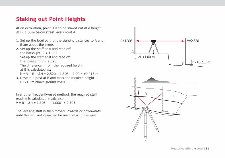
Staking out Point Heights
At an excavation, point B is to be staked out at a height iH = 1.00 m below street level (Point A).
1. Set up the level so that the sighting distances to A and B are about the same.
2. Set up the staff at A and read off the backsight: R = 1.305. Set up the staff at B and read off the foresight: V = 2.520. The difference h from the required height at B is calculated as: h = V – R – iH = 2.520 – 1.305 – 1.00 = +0.215 m
3. Drive in a post at B and mark the required height (0.215 m above ground level).
In another frequently-used method, the required staff reading is calculated in advance:V = R – iH = 1.305 – (-1.000) = 2.305
The levelling staff is then moved upwards or down wards until the required value can be read off with the level.
12 | Measuring with the Level
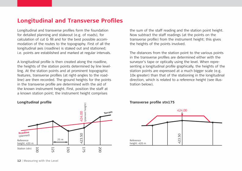
Longitudinal and Transverse Profiles
Longitudinal and transverse profiles form the foundation for detailed planning and stakeout (e.g. of roads), for calculation of cut & fill and for the best possible accom-modation of the routes to the topography. First of all the longitudinal axis (road line) is staked out and stationed; i.e. points are established and marked at regular intervals. A longitudinal profile is then created along the roadline, the heights of the station points deter mined by line level-ling. At the station points and at pro minent topographic fea tures, transverse profiles (at right-angles to the road-line) are then recorded. The ground heights for the points in the transverse profile are determined with the aid of the known instrument height. First, po sition the staff at a known station point; the instru ment height comprises
the sum of the staff reading and the station point height. Now subtract the staff readings (at the points on the transverse profile) from the instrument height; this gives the heights of the points involved.
The distances from the station point to the various points in the transverse profiles are determined either with the surveyor’s tape or optically using the level. When repre-senting a longitudinal profile graphi cally, the heights of the station points are expres sed at a much bigger scale (e.g. 10x greater) than that of the stationing in the longi tu dinal direction, which is related to a reference height (see illus-tration below).
Longitudinal profile Transverse profile stn175
100
125
150
175
200
423.50
424.00
424.00
423.50
Terrain
Roadline
(planned)
Referenceheight: 420 m
(pla
nned
hei
ght)
25 m Referenceheight: 420 m
Station (stn)

Digital Level and Rotating Laser | 13
The Digital Level
Leica Geosystems was the pioneer of digital levels with the world’s first level to digitally process images to deter-mine heights and distances; the bar code on a staff is read com pletely auto matically and electronically (see illus-tration).
The staff reading and the distance are displayed digi tally and can be recor ded; the heights of the staff stations are cal cu lated continuously and so there can be no errors re lated to reading, recording and calculating. Leica Geo systems also offers software packages to post-process the recorded data.
The Rotating Laser
If, for example on a large construction site, a large num-ber of points at different heights need to be staked out or monitored, it often makes sense to use a rotating laser. With this type of instrument, a rotating laser beam sweeps out a horizontal plane, which serves as the refer-ence plane for staking out or monitoring heights.
A laser receiver is slid up/down a levelling staff until it detects the laser beam; the height can then be read directly off the staff. There is no need for an observer at the instrument station.
A digital level is recom mended for use where a lot of lev-elling needs to be carried out; under these circumstances time savings can amount to 50 %.

14 | The Total Station
The Total Station
Total stations are used wherever the positions and heights of points, or merely their positions, need to be determined. A total station consists of a theodolite with a built-in distance meter, enabling it to simultaneously mea-sure angles and distances. Today’s electronic total stations all have an opto-electronic distance meter (EDM) and elec-tronic angle scanning. The coded scales of the horizontal and vertical circles are scanned electronically, and then the angles and distances are displayed digitally. The horizon-
tal distance, the height difference and the coordinates are calculated automatically and all measurements and addi-tional information is recorded.
Leica Geosystems total stations are supplied with a soft-ware package that enables most survey tasks to be carried out easily, quickly and efficiently. The most important of these pro grams are presented later in this document.
The Total Station | 15
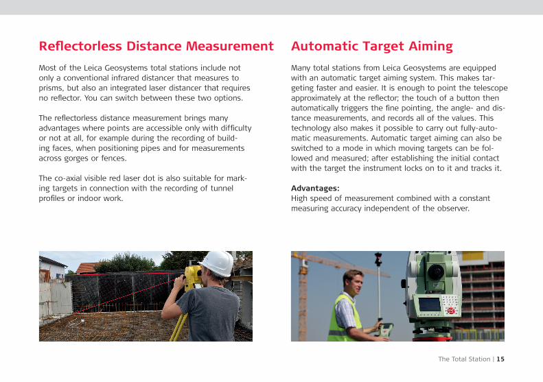
Reflectorless Distance Measurement
Most of the Leica Geosystems total stations include not only a conventional infra red distancer that mea su res to prisms, but also an integrated laser distancer that requires no reflector. You can switch between these two options.
The reflectorless distance measurement brings many advantages where points are accessible only with difficulty or not at all, for example during the recording of build-ing faces, when positioning pipes and for measurements across gorges or fences.
The co-axial visible red laser dot is also suitable for mark-ing targets in connection with the recording of tunnel profiles or indoor work.
Automatic Target Aiming
Many total stations from Leica Geosystems are equipped with an automatic target aiming system. This makes tar-geting faster and easier. It is enough to point the tele scope approximately at the reflector; the touch of a button then automatically triggers the fine pointing, the angle- and dis-tance measurements, and records all of the values. This technology also makes it possible to carry out fully-auto-matic measurements. Automatic target aiming can also be switched to a mode in which moving targets can be fol-lowed and measured; after establishing the initial contact with the target the instrument locks on to it and tracks it.
Advantages: High speed of measurement combined with a constant measuring accuracy independent of the observer.
16 | Polar and Cartesian Coordinates
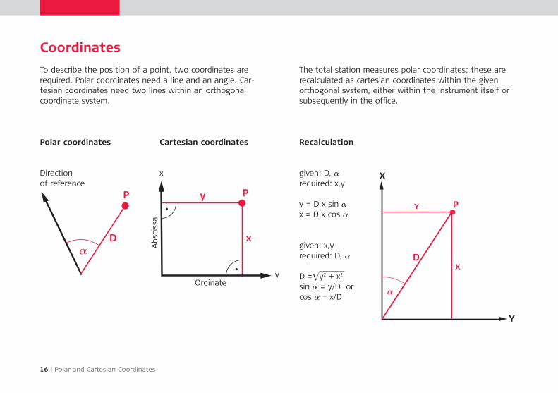
Coordinates
To describe the position of a point, two coordinates are required. Polar coordinates need a line and an angle. Car-tesian coordinates need two lines within an ortho gonal coordinate system.
The total station measures polar coordinates; these are recalculated as cartesian coordinates within the given orthogonal system, either within the instrument itself or subsequently in the office.
Polar coordinates Cartesian coordinates
Direction of reference
x
Ordinate
Recalculation
given: D, a required: x,y
y = D x sin a x = D x cos a
Absc
issa
y
given: x,yrequired: D, a
D =Ey2 + x2
sin a = y/D orcos a = x/D
Horizontal and Vertical Angles | 17
Measuring Angles
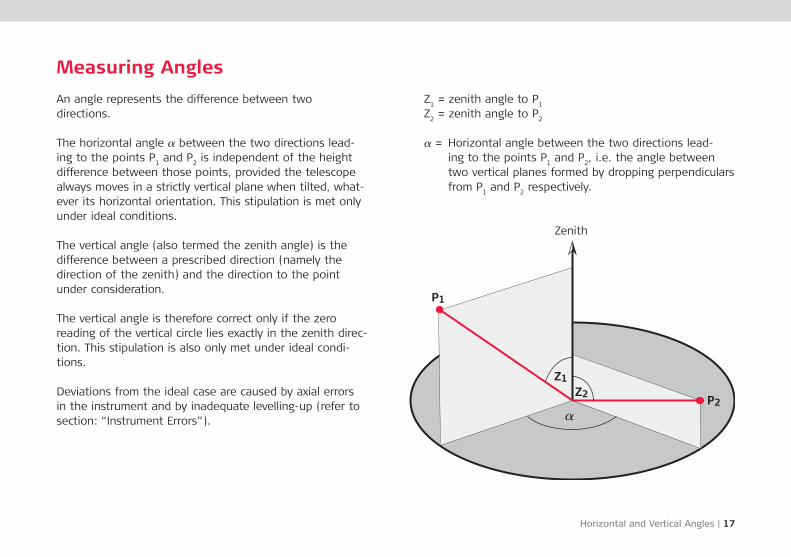
An angle represents the difference between two directions.
The horizontal angle a between the two directions lead-ing to the points P
1 and P
2 is independent of the height
difference between those points, provided the telescope always moves in a strictly vertical plane when tilted, what-ever its horizontal orientation. This stipulation is met only under ideal conditions.
The vertical angle (also termed the zenith angle) is the difference between a prescribed direction (namely the direction of the zenith) and the direction to the point under consideration.
The vertical angle is therefore correct only if the zero reading of the vertical circle lies exactly in the zenith direc-tion. This stipulation is also only met under ideal condi-tions.
Deviations from the ideal case are caused by axial errors in the instrument and by inadequate levelling-up (refer to section: “Instrument Errors”).
Z1 = zenith angle to P
1
Z2 = zenith angle to P
2
a = Horizontal angle between the two directions lead-ing to the points P
1 and P
2, i.e. the angle between
two vertical planes formed by dropping perpendiculars from P
1 and P
2 respectively.
Zenith
18 | Instrument Errors
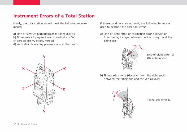
Instrument Errors of a Total Station
Ideally, the total station should meet the following require-ments:
a) Line of sight ZZ perpen dicular to tilting axis KKb) Tilting axis KK perpen dicular to vertical axis VVc) Vertical axis VV strictly verticald) Vertical-circle reading precisely zero at the zenith
If these conditions are not met, the following terms are used to describe the particular errors:
a) Line-of-sight error, or colli mation error c (deviation from the right angle bet ween the line of sight and the tilting axis)
b) Tilting-axis error a (devia tion from the right angle between the tilting axis and the vertical axis)
Line-of-sight error (c)(Hz collimation)
Tilting-axis error (a)
V
V
K
K
Z
Z
c
a
Instrument Errors | 19
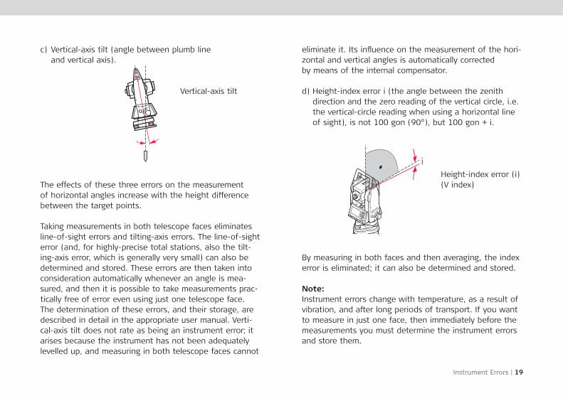
c) Vertical-axis tilt (angle between plumb line and vertical axis).
eliminate it. Its influence on the measure ment of the hori-zontal and vertical angles is auto matically corrected by means of the internal compensator.
d) Height-index error i (the angle between the zenith direction and the zero reading of the vertical circle, i.e. the vertical-circle reading when using a horizontal line of sight), is not 100 gon (90°), but 100 gon + i.
Vertical-axis tilt
The effects of these three errors on the measurement of horizontal angles increase with the height difference between the target points.
Taking measurements in both telescope faces eliminates line-of-sight errors and tilting-axis errors. The line-of-sight error (and, for highly-precise total stations, also the tilt-ing-axis error, which is generally very small) can also be determined and stored. These errors are then taken into consideration automati cally whenever an angle is mea-sured, and then it is possible to take mea sure ments prac-tically free of error even using just one telescope face. The deter mination of these errors, and their storage, are described in detail in the appropriate user manual. Verti-cal-axis tilt does not rate as being an instrument error; it arises because the instrument has not been adequately levelled up, and measuring in both telescope faces cannot
By measuring in both faces and then averaging, the index error is eliminated; it can also be determined and stored.
Note:Instrument errors change with temperature, as a result of vibration, and after long periods of transport. If you want to measure in just one face, then immediately before the measurements you must determine the instrument errors and store them.
Height-index error (i)(V index)
i
20 | Inspecting the EDM
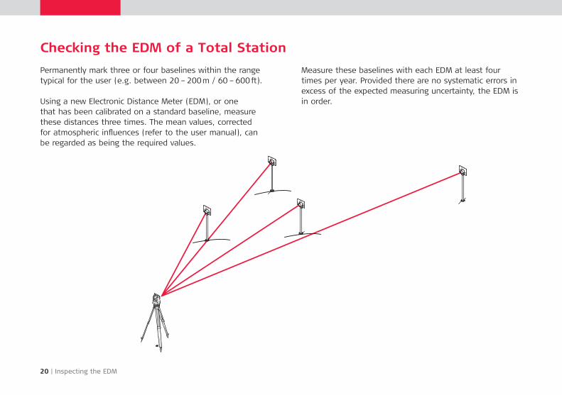
Checking the EDM of a Total Station
Permanently mark three or four baselines within the range typical for the user (e.g. between 20 – 200 m / 60 – 600 ft).
Using a new Electronic Distance Meter (EDM), or one that has been cali brated on a standard baseline, measure these distances three times. The mean values, corrected for atmospheric influences (refer to the user manual), can be regarded as being the required values.
Measure these baselines with each EDM at least four times per year. Provided there are no systematic errors in excess of the expected measuring uncertainty, the EDM is in order.
Setup to Measure | 21
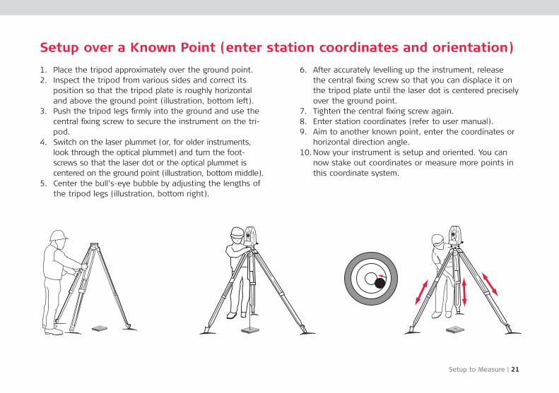
Setup over a Known Point (enter station coordinates and orientation)
1. Place the tripod approximately over the ground point.2. Inspect the tripod from various sides and correct its
position so that the tripod plate is roughly horizontal and above the ground point (illustration, bottom left).
3. Push the tripod legs firmly into the ground and use the central fixing screw to secure the instrument on the tri-pod.
4. Switch on the laser plummet (or, for older instruments, look through the optical plummet) and turn the foot-screws so that the laser dot or the optical plummet is centered on the ground point (illustration, bottom middle).
5. Center the bull’s-eye bubble by adjusting the lengths of the tripod legs (illustration, bottom right).
6. After accurately levelling up the instrument, release the central fixing screw so that you can displace it on the tripod plate until the laser dot is centered precisely over the ground point.
7. Tighten the central fixing screw again.8. Enter station coordinates (refer to user manual).9. Aim to another known point, enter the coordinates or
horizontal direction angle.10. Now your instrument is setup and oriented. You can
now stake out coordinates or measure more points in this coordinate system.
22 | Setup to Measure
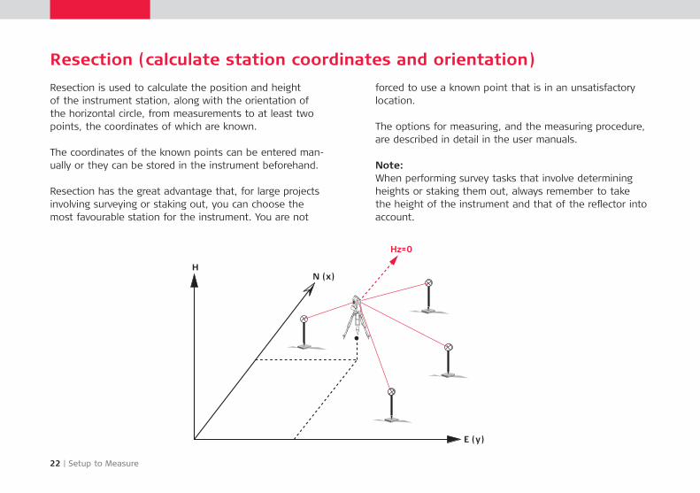
Resection (calculate station coordinates and orientation)
Resection is used to calculate the position and height of the instrument station, along with the orientation of the horizontal circle, from measurements to at least two points, the coordinates of which are known.
The coordinates of the known points can be entered man-ually or they can be stored in the instrument beforehand.
Resection has the great advantage that, for large projects involving surveying or staking out, you can choose the most favourable station for the instrument. You are not
forced to use a known point that is in an unsatisfactory location.
The options for measuring, and the measuring procedure, are described in detail in the user manuals.
Note:When performing survey tasks that involve determining heights or staking them out, always remember to take the height of the instrument and that of the reflector into account.
Simple Surveying Tasks | 23
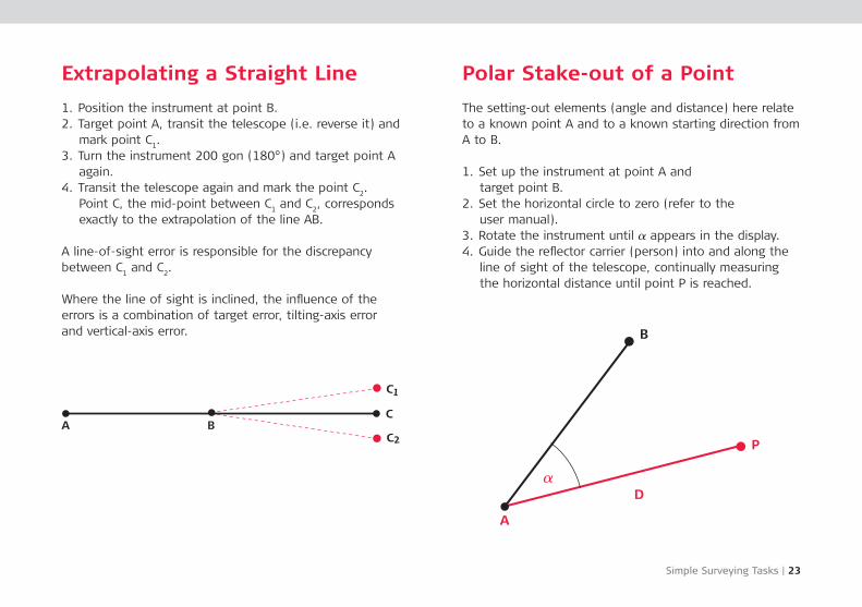
Extrapolating a Straight Line
1. Position the instrument at point B.2. Target point A, transit the telescope (i.e. reverse it) and
mark point C1.
3. Turn the instrument 200 gon (180°) and target point A again.
4. Transit the telescope again and mark the point C2.
Point C, the mid-point between C1 and C
2, corresponds
exactly to the extrapolation of the line AB.
A line-of-sight error is re sponsible for the discre pancy between C
1 and C
2.
Where the line of sight is inclined, the influence of the errors is a combination of target error, tilting-axis error and vertical-axis error.
Polar Stake-out of a Point
The setting-out elements (angle and distance) here relate to a known point A and to a known starting direction from A to B.
1. Set up the instrument at point A and target point B.
2. Set the horizontal circle to zero (refer to the user manual).
3. Rotate the instrument until a appears in the display.4. Guide the reflector carrier (person) into and along the
line of sight of the telescope, continually measuring the horizontal distance until point P is reached.
A B
C1
C2
C
24 | Simple Surveying Tasks
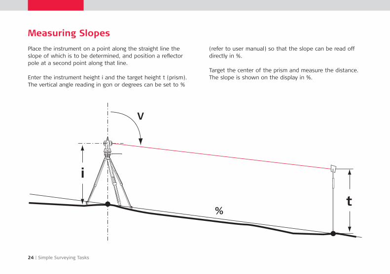
Measuring Slopes
Place the instrument on a point along the straight line the slope of which is to be determined, and position a reflector pole at a second point along that line.
Enter the instrument height i and the target height t (prism). The vertical angle reading in gon or degrees can be set to %
(refer to user manual) so that the slope can be read off directly in %.
Target the center of the prism and measure the distance. The slope is shown on the display in %.
t
i
V
%
Simple Surveying Tasks | 25
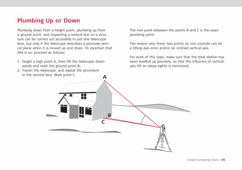
Plumbing Up or Down
Plumbing down from a height point, plumbing up from a ground point, and inspecting a vertical line on a struc-ture can be carried out accurately in just one tele scope face, but only if the telescope describes a pre cisely verti-cal plane when it is moved up and down. To ascertain that this is so, proceed as follows:
1. Target a high point A, then tilt the telescope down-wards and mark the ground point B.
2. Transit the telescope, and repeat the procedure in the second face. Mark point C.
The mid-point between the points B and C is the exact plumbing point.
The reason why these two points do not coincide can be a tilting-axis error and/or an inclined vertical axis.
For work of this type, make sure that the total station has been levelled up pre cisely, so that the influence of vertical-axis tilt on steep sights is minimized.
A
BC
26 | Measuring with a Total Station
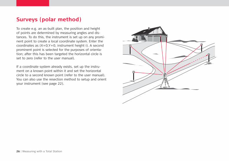
Surveys (polar method)
To create e.g. an as-built plan, the position and height of points are determined by measuring angles and dis-tances. To do this, the instrument is set up on any promi-nent point to create a local coordinate system. Enter the coordinates as (X = 0,Y = 0, instrument height i). A second prominent point is selected for the purposes of orienta-tion; after this has been targeted the horizontal circle is set to zero (refer to the user manual).
If a coordinate system already exists, set up the instru-ment on a known point within it and set the horizontal circle to a second known point (refer to the user manual). You can also use the resection method to setup and orient your instrument (see page 22).
Application Programs | 27
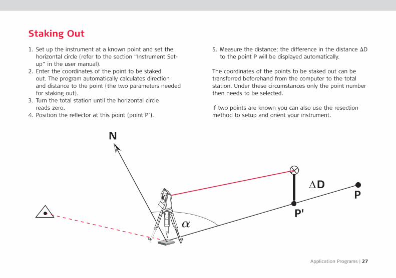
Staking Out
1. Set up the instrument at a known point and set the horizontal circle (refer to the sec tion “Instrument Set-up” in the user manual).
2. Enter the co or dinates of the point to be staked out. The pro gram automatically cal culates direction and dis tance to the point (the two para me ters needed for staking out).
3. Turn the total station until the horizontal circle reads zero.
4. Position the reflector at this point (point P’).
5. Measure the distance; the difference in the distance iD to the point P will be displayed automatically.
The coordi nates of the points to be staked out can be trans ferred beforehand from the computer to the total station. Under these circum stances only the point number then needs to be selected.
If two points are known you can also use the resection method to setup and orient your instrument.
P'
DP
N
a
28 | Application Programs
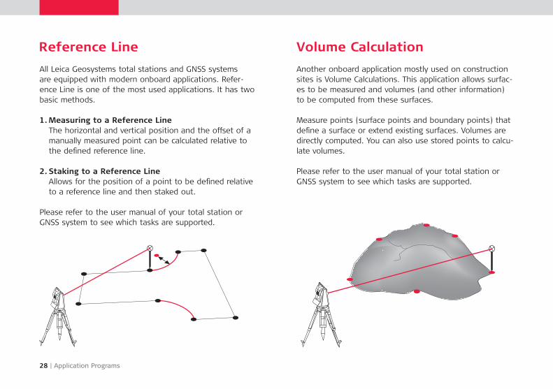
Reference Line
All Leica Geosystems total stations and GNSS systems are equipped with modern onboard applications. Refer-ence Line is one of the most used applications. It has two basic methods.
1. Measuring to a Reference Line The horizontal and vertical position and the offset of a manually measured point can be calculated relative to the defined reference line.
2. Staking to a Reference Line Allows for the position of a point to be defined relative to a reference line and then staked out.
Please refer to the user manual of your total station or GNSS system to see which tasks are supported.
Volume Calculation
Another onboard application mostly used on construction sites is Volume Calculations. This application allows surfac-es to be measured and volumes (and other information) to be computed from these surfaces.
Measure points (surface points and boundary points) that define a surface or extend existing surfaces. Volumes are directly computed. You can also use stored points to calcu-late volumes.
Please refer to the user manual of your total station or GNSS system to see which tasks are supported.
Application Programs | 29
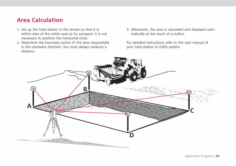
Area Calculation
1. Set up the total station in the terrain so that it is within view of the entire area to be surveyed. It is not necessary to position the horizontal circle.
2. Determine the boundary points of the area sequentially in the clockwise direction. You must always measure a distance.
3. Afterwards, the area is calculated and displayed auto-matically at the touch of a button.
For detailed instructions refer to the user manual of your total station or GNSS system.
30 | Application Programs
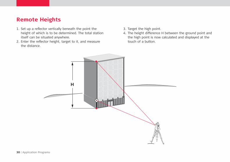
Remote Heights
1. Set up a reflector verti cally beneath the point the height of which is to be determined. The total station itself can be situated anywhere.
2. Enter the reflector height, target to it, and measure the distance.
3. Target the high point.4. The height difference H between the ground point and
the high point is now calculated and displayed at the touch of a button.
H
Application Programs | 31
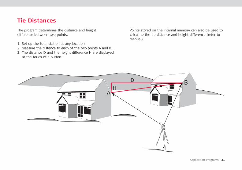
Tie Distances
The program determines the distance and height difference between two points.
1. Set up the total station at any location.2. Measure the distance to each of the two points A and B.3. The distance D and the height difference H are displayed
at the touch of a button.
Points stored on the internal memory can also be used to calculate the tie distance and height difference (refer to manual).
AH
D B
32 | Application Programs
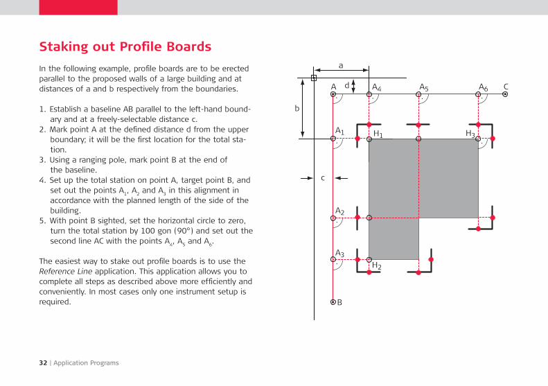
In the following example, profile boards are to be erected parallel to the pro posed walls of a large building and at distances of a and b respectively from the boundaries.
1. Establish a baseline AB parallel to the left-hand bound-ary and at a freely-selectable distance c.
2. Mark point A at the defined distance d from the upper boundary; it will be the first location for the total sta-tion.
3. Using a ranging pole, mark point B at the end of the baseline.
4. Set up the total station on point A, target point B, and set out the points A
1, A
2 and A
3 in this align ment in
accordance with the planned length of the side of the building.
5. With point B sighted, set the horizontal circle to zero, turn the total station by 100 gon (90°) and set out the second line AC with the points A
4, A
5 and A
6.
The easiest way to stake out profile boards is to use the Reference Line application. This application allows you to complete all steps as described above more efficiently and conveniently. In most cases only one instrument setup is required.
Staking out Profile Boards
A A4 A5 A6 C
H3H1
H2
A1
A2
A3
B
c
b
a
d
Surveying with GNSS | 33
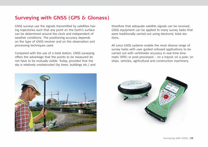
Surveying with GNSS (GPS & Glonass)
GNSS surveys use the signals transmitted by satellites hav-ing trajectories such that any point on the Earth’s surface can be determined around the clock and independent of weather conditions. The positioning accuracy depends on the type of GNSS receiver and on the observation and processing techniques used.
Compared with the use of a total station, GNSS surveying offers the advantage that the points to be measured do not have to be mutually visible. Today, provided that the sky is relatively unobstructed (by trees, buildings etc.) and
there fore that adequate satellite signals can be received, GNSS equipment can be applied to many survey tasks that were traditionally carried out using electronic total sta-tions.
All Leica GNSS systems enable the most diverse range of survey tasks with user guided onboard applications to be carried out with centimeter accuracy in real-time kine-matic (RTK) or post-processed – on a tripod; on a pole; on ships, vehicles, agrilcultural and construction machinery.
34 | GNSS Reference Stations
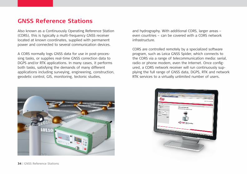
GNSS Reference Stations
Also known as a Conti nuously Operating Reference Station (CORS), this is typically a multi-frequency GNSS receiver located at known coordinates, supplied with permanent power and connected to several communication devices.
A CORS normally logs GNSS data for use in post-proces-sing tasks, or supplies real-time GNSS correction data to DGPS and/or RTK applications. In many cases, it performs both tasks, satisfying the demands of many different applications including surveying, engineering, construction, geodetic control, GIS, monitoring, tectonic studies,
and hydrography. With additional CORS, larger areas – even countries – can be covered with a CORS network infrastructure.
CORS are controlled remotely by a specialized software program, such as Leica GNSS Spider, which connects to the CORS via a range of telecommunication media: serial, radio or phone modem, even the Internet. Once config-ured, a CORS network receiver will run continuously sup-plying the full range of GNSS data, DGPS, RTK and network RTK services to a virtually unlimited number of users.
More Booklets | 35
Are you interested in learning more about this topics? Leica Geosystems provides more reference booklets online at:
http://www.leica-geosystems.com/booklets/
Leica Geosystems Construction ToolsLeica BuilderLeica SmartPole and SmartStationIntroduction to GPSGuide to Reference Stations

Illustrations, descriptions and technical data are not binding and may be changed. Printed in Switzerland – Copyright Leica Geosystems AG, Heerbrugg, Switzerland, 2013.722510en – I.13 – RVA
Leica Geosystems AG Heerbrugg, Switzerland www.leica-geosystems.com
Whether building a house or a bridge, a map or an aircraft,you need reliable measurements. So when it has to be right,professionals trust Leica Geosystems to help them collect,analyze, and present spatial information.
With close to 200 years of pioneering solutions to measure theworld, Leica Geosystems is best known for its broad array ofproducts that capture data accurately, model quickly, analyzeeasily, and visualize and present spatial information. Those whouse Leica Geosystems’ products every day trust them for theirdependability, the value they deliver, and the superiorcustomer support.
Precision, value, and service from Leica Geosystems.
When it has to be right.