surveying and road design fundamentals - · pdf filesurveying and road design fundamentals ......
TRANSCRIPT

WPC #27810 07/09
AREA MANAGER ROADS CERTIFICATION PROGRAM
AMRC 2012 SURVEYING AND ROAD DESIGN FUNDAMENTALS
STUDENT GUIDE
FOR EDUCATIONAL PURPOSES ONLY
April, 2006

WPC #27810 07/09
2009 by
British Columbia Institute of Technology
Burnaby, British Columbia
All rights reserved. No part of this document may be reproduced in any form, without permission in
writing from BCIT.
Material subject to copyright has been reproduced under licence from Access Copyright. Resale or
further copying of this material is strictly prohibited.

WPC #27810 07/09 1
Course Introduction
This is the Surveying and Road Design Fundamentals course in the Area Manager Roads Certification Program. You will earn 2.0 credits when you finish this course.
Table of Contents Page Course Introduction .................................................................................. 1
Course Outline .......................................................................................... 2
Course Details ........................................................................................... 4
Evaluation and Study ................................................................................ 5
Final Exam ................................................................................................ 6
WPC #27810 07/09 2
Course Outline
Course Title: Surveying and Road Design Fundamentals
Course Number: AMRC 2012
Number of Credits: 2.0
Course Objectives
Upon successful completion of this course, you will be able to: 1. perform basic mathematical and trigonometric calculations related
to survey calculations 2. describe the types of linear measurements and the types of
equipment used in the measurement of distance and length 3. describe equipment used in levelling and elevation measurement
4. determine measured angles displayed on survey equipment
5. describe open and closed traverses
6. determine map and plan distances utilizing various types of scales
7. state and define the terms and general requirements for the lay out
and survey of construction work and structures
8. describe the highway design process and the levels of construction cost estimates
9. describe the fundamentals of road classification, driver and vehicle
performance, traffic characteristics and environmental requirements
10. describe and explain the concept of sight distances
11. describe the basic elements of horizontal and vertical highway design
12. describe the various types of intersections and the criteria used to
design them.

WPC #27810 07/09 3
Course Description
This course is intended to provide an introduction to the fundamental principles of field surveying and road design fundamentals.
Prerequisites
None.
Suggested Prerequisites
None.

WPC #27810 07/09 4
Course Details
Course Modules
Module 1 Basic Principles of Surveying and Mathematics Module 2 Measurement of Distance and Elevation –
Equipment and Procedures Module 3 Angle Measurements, Traverses, and Curves Module 4 Office Methods, Site Surveys, and Construction Layout Module 5 Highway Design Process Module 6 Design Criteria Module 7 Sight Distance Module 8 Horizontal Alignment Module 9 Vertical Alignment Module 10 Intersections
Course Materials
Student Guide Course Manual Texts
Required Text(s) and Equipment
Transportation Association of Canada. (1999). Geometric Design Guide for Canadian Roads, Part 1. (TAC Manual)
Engineering Branch, Province of British Columbia. (2001, January). BC
Supplement to the Transportation Association of Canada for Canadian Roads.
Recommended Text(s) and Equipment
American Association of State Highway and Transportation Officials. (1994). A Policy on Geometric Design of Highways and Streets. (AASHTO Policy)

WPC #27810 07/09 5
Evaluation and Study
Student Evaluation
Your course mark will be based on a possible total of 100 marks as follows: Final Examination 100 marks
Note: Students must achieve a minimum passing mark of 75% on the final exam.
The Final Exam will be held at locations agreed with the MoT. It will be a closed book exam, i.e., the learner will not be allowed to take the course manual and texts into the exam.
Study Procedures
The course modules are self-contained and cover a particular subject or a group of related items. Each module begins with the specific objectives you should be able to achieve, then describes and explains the subject and ends with a series of self-test questions. These self-test questions should be correctly completed without reference to the manual before you proceed to the next module.
Module Self-Tests
The module self-test solutions are located in this student guide.

WPC #27810 07/09 6
Final Exam
When you have finished Module 10, you should send in your completed “Request for Exam” form. You will be asked to write a “closed book” exam in a specified period of time and the proctor (normally a professional engineer or equivalent or a person in an excluded person) will sign the form confirming that you wrote the exam in the allotted time and place. The “Request for Exam” form is page 7 of this guide. The form should be sent to:
Civil Engineering Technology Distance Education Dept., Room 286, Building SW3 BCIT 3700 Willingdon Avenue Burnaby, BC V5G 3H2
Or Faxed to:
Civil Engineering Technology Distance Education Dept., at (604) 436-6113

WPC #27810 07/09 7
Request for Examination
AMRC 2012Surveying and Road Design Fundamentals
I am prepared to write my final examination for the above course. PLEASE PRINT:
Student Name:
Address:
Postal Code:
Student Number:
Phone Number:
E-mail Address:
PLEASE FORWARD MY EXAMINATION TO:
Examination Supervisor Name:
Address:
Postal Code:
E-mail Address:
I agree to supervise the AMRC 2012 – Surveying and Road Design Fundamentals examination.
Examination Supervisor Signature Examination Supervisor Name (please print)
Position or Professional Designation (Professional Engineer, etc.)
Membership Number (if appropriate)
Phone Number

WPC #27810 07/09
AREA MANAGER ROADS CERTIFICATION PROGRAM
AMRC 2012 SURVEYING AND ROAD DESIGN FUNDAMENTALS
Self-Test Answers

WPC #27810 07/09 9
SELF-TEST ANSWERS
(Module 1 – Basic Principles of Surveying and Mathematics)
1. Plane surveys are small or local survey projects where the earth’s curvature is not a factor in the
results obtained and need not be taken into account.
Geodetic surveys are larger scale survey projects where the curvature of the earth must be taken into account in the reduction of observed data.
2. Types of surveys which may be directly related to land subdivision and development projects are:
Cadastral or land surveying — The determination of land or property boundaries and corners
and the preparation of legal plans of such land. Route surveys — Surveys of proposed routes and technical details for engineering and
construction projects associated with transportation and communication. Topographic surveys — Obtaining data for the preparation of maps or plans where landform
and elevation information is graphically represented. Site surveys — Obtaining field data for the preparation of maps or plans showing existing
features and structures of an area or site, typically so that new features or structures may be planned.
Aerial surveys — Aerial photographs and preparation of information display from such
photography through digital means, maps and mosaics or topographic representation.

WPC #27810 07/09 10
3. Add:
4. Subtract:
5. Multiply:

WPC #27810 07/09 11
Computer c) using degrees and decimals
6. Divide:

WPC #27810 07/09 12
Compute c) using degrees and decimals
7. Azimuth bearings of the lines A to B; B to C; C to D.

WPC #27810 07/09 13
8. Quadrant bearings for the lines A to B; B to C; C to D; D to E.

WPC #27810 07/09 14
9. Quadrant bearings for the lines B to C; C to D; D to E; E to F; F to G; G to H; H to I; I to A.

WPC #27810 07/09 15
10. a. Envision the slope distance and the measured angle as part of a right triangle, as shown below. The slope distance is the hypotenuse (c) while the measured angle is 17°13'. The horizontal distance is the adjacent side (b) and the vertical distance is the side opposite (a).
b.
11. The calculated distances may be checked using Pythagoras’ Theorem, namely that:

WPC #27810 07/09 16
SELF-TEST ANSWERS
(Module 2 – Measurement of Distance and Elevation – Equipment and Procedures)
1. Four of the following should be indicated in your answer:
Pacing — low accuracy; impeded in difficult terrain; good for rough measurement or field orientation only.
Odometer — moderately accurate on smooth, level surface; measures slope distance only. EDM — highly accurate; measures slope distance — may need to convert to horizontal
distance. Chain/Tape — very accurate if carried out correctly using survey chain; tape less accurate. Stadia — moderate accuracy (lower than tape, higher than pacing).
2. Review Section 2.3.2. 3. Survey information can be transformed into finished drawings without any hand written or booked
data. Review Section 2.5. 4. 1. tripod 2. level 3. horizontal plain of equal elevation (height of instrument) 4. levelling rod 5. bench mark 6. temporary or new bench mark 7. rod reading 5. Dumpy level — Plate bubble mounted on telescope
Tilting level — Bull’s-eye bubble mounted on instrument base; plate bubble with split image attached to telescope.
Automatic level — Bull’s-eye bubble mounted on instrument base; internal suspended levelling device controlling optics of telescope.

WPC #27810 07/09 17
6. Checks after reading each type of level:
Dumpy — Check telescope plate bubble to ensure it remains in centred position.
Tilting — Check split bubble image to ensure it is in coincidence after reading.
Automatic — Tap telescope lightly while looking through telescope to ensure internal levelling mechanism is moving freely.
7. A rod is “rocked” to ensure that a point perpendicular to the horizontal plain of equal elevation is
sighted by the surveyor and read as the correct rod reading. This will be the lowest rod value as sighted by the instrument.

WPC #27810 07/09 18
SELF-TEST ANSWERS
(Module 3 – Angle Measurements, Traverses, and Curves)
1.
2. Micrometer readings a. horizontal 40° 7' 18" b. vertical 96° 6' 30" c. horizontal 235° 56' 30" d. horizontal 05° 13' 40" e. vertical 84° 13' 30" 3. 180° 35' 40" / 2 = 94° 47' 50" because you have two readings FL and FR (two sets) 4. 113° 58' 45" + 360º = 473° 58' 45" because you have passed 360º on the circle 473° 58' 45" / 5 because you have five sets

WPC #27810 07/09 19
5. Review Section 3.2. 6. a. Horizontal distances to top and bottom of wall. Top of Wall
HD1 = SD cos α (22°06') = 34.828 m 0.92653 = 32.269 m (horizontal distance to top of wall) V1 = SD sin α (22°06') = 34.828 m 0.37622 = 13.103 m (wall height from HI to top) Bottom of wall
HD2 = SD cos α (31°45') = 37.293 m 0.85035 = 31.712 m (horizontal distance to bottom of wall) V1 = SD sin α (31°45') = 37.293 m 0.52621 = 19.624 m (wall height from HI to bottom) b. The wall is not vertical. The horizontal distance to the toe of the wall is 31.712 m, less than the
horizontal distance to the top of the wall, which is 32.269 m.

WPC #27810 07/09 20
c. Top of wall elevation: Top elev. = HI + V1
= 907.131 + 13.103 = 920.234 Bottom of wall: Bottom elev. = HI – V2
= 907.131 – 19.624 = 887.507 Height of wall: H = Top – Bottom = 920.234 – 887.507 = 32.727 m 7. Review Section 3.10.1. 8. Review Section 3.10.2. 9. a. The coordinates of point “B” in the following diagram: Latitude = Distance cos bearing = 401.76 cos 71°15' = 401.76 0.321439 = 129.142 m NORTH Departure = Distance sin bearing = 401.76 sin 71°15' = 401.76 0.946930 = 380.439 m EAST Coordinates of Point “B” 1,741.602 N + 129.142 N = Point 962.847 E + 381.439 E = “B”
1,870.744 N1,343.286 E

WPC #27810 07/09 21
b. The coordinates of point “Y” in the following diagram: Bearing Line BY Bearing of AB (Quadrant) N 71°15' E Bearing of AB (Azimuth) 71°15' Plus deflection angle (Rt) 149°36' = Bearing of BY (Azimuth) 220°51' = Bearing of BY (Quadrant) 220°51' – 180° = S 40°51' W Latitude of Line BY = Distance cos bearing = 671.040 cos 40°51' = 671.040 0.756425 = 507.591 m SOUTH Distance of Line BY = Distance sin bearing = 671.040 cos 40°51' = 671.040 0.654081 = 438.914 m WEST
Coordinates of Point “Y”
Point – 507.591 m SOUTH = Point “B” – 438.914 m WEST = “Y”
1,870.744 N 1,343.286 E
1,363.153 N 904.372 E

WPC #27810 07/09 22
SELF-TEST ANSWERS
(Module 4 – Office Methods, Site Surveys, and Construction Layout)
1. 7500.0 m 2. 62 m 3. a. Rising to the north b. 2 m c. North is steeper d. 126 m e. 110 m f. + 9.52% 4.

WPC #27810 07/09 23
5.
6. a. saddle b. right angles c. spaced d. closed e. elevation 7. Control points should be set outside of the actual construction area so that construction points (batter
boards, hubs, stakes, etc.) can be replaced if damaged or destroyed during construction. 8. Important junctions are tied to the control net during construction to:
provide a final check on the accuracy of construction layout provide a reference so points can be re-established during construction.
9. Typical batter board arrangement:
elevation and alignment hubs set “2 × 4” riser stakes set vertically on either side of excavation at each hub batter board or cross head nailed to riser stakes at calculated height (drop board height) above
hub batter board set level and centreline of pipe marked with a nail

WPC #27810 07/09 24
10. Pipe slope is !2.625%, or 0.02625 m/metre of distance Elevation difference in 60 metres = 60 C 0.02625 = 1.575 m Elevation @ Sta. 16+00 = 65.000 Elevation @ Sta. 16+60 = 65.000 ! 1.575 = 63.425 11. Pipe invert elevation @ sta. 17+20:
= 65.000 – (120 m 0.0265) = 65.000 – 3.15 = 61.850 Elevation of top of batter board (@ 4.0 m drop): = 61.850 + 4.0 m = 65.850 Batter board height above hub: = batter board top – hub elev. = 65.850 – 65.100 = 0.750 m
6. a. 1.5 5.67 m = 8.505 m b. 1.5 5.67 m = 8.505 m c. ? + 12.00 m + ? = distance from LT toe to RT toe 8.505 + 12.00 + 8.505 = 29.010 m

WPC #27810 07/09 25
SELF-TEST ANSWERS
(Module 5 – Highway Design Process)
1. Transportation Act and the BC Motor Vehicle Act. Review the Overview in Section 5.1. 2. Public needs, political will, finance, and skills. Review Section 5.1.1. 3. Phase 1 Needs Study Phase 2 Feasibility Study and Preliminary Design Phase 3 Functional Design Phase 4 Detailed Design Phase 5 Construction and Records Phase 6 Post Construction Review Section 5.1.2. 4. Classes A, B, C, and D. Review Section 5.8.

WPC #27810 07/09 26
SELF-TEST ANSWERS
(Module 6 – Design Criteria)
1. Review Section 6.3.
2. Main movement, transition, distribution, collection, access and termination.
3. Review Section 6.1.
4. Review Section 6.1.
5. Specific vehicle categories influence the design of various classifications of highway. Review Section 6.2.
6. Review Section 6.3.
7. efficiency (capacity and level of service) and speed
8. Desired speed, design speed, operating speed, running speed and posted speed. Review Section 6.4.
9. Review Section 6.5.
10. Value engineering reduces cost but one must be aware that savings may affect quality in many areas. Review Section 6.6.
11. Review Section 6.7.

WPC #27810 07/09 27
SELF-TEST ANSWERS
(Module 7 – Design Criteria)
1. perception — reaction time driver — eye height vehicle operating speed object height coefficient of pavement friction 2. SSD is the stopping sight distance and is the sum of the distance traveled during the perception and
reaction time and the braking distance. Review Section 7.2. 3. PSD is the passing sight distance and it is described in Section 7.3. 4. DSD is the decision sight distance and it is described in Section 7.4.

WPC #27810 07/09 28
SELF-TEST ANSWERS
(Module 8 – Horizontal Alignment)
1. R = 2V
127(e f ) Review Section 8.1.
2. Superelevation is used to conteract the centrifugal force along a curve. Review Section 8.2. 3. The spiral length is used to apply the superelevation to the road way. Review Section 8.2. 4. tangent length or AD (apex distance) 5. b. 6. b. 7. b. 8. a, b, and c may adversely affect stopping sight distance around the inside of a curve. d. Widening the shoulder may improve sight distance, unless it results in parking opportunities
which, without control, may impact sight distance. 9. a. 230 m b. 390 m c. 130 m
d. 440 m

WPC #27810 07/09 29
10. Using Table 330.01.01 of the BC supplement to the Geometric Design Guide, minimum radius for UFD 110 = 600 m. The use of 700 m radius is acceptable.
) = 15E
Tangent length = R tan )/2 = 700 tan (7.5E) = 92.157 m
Chainage at BC = Sta. 0+946.627 – 92.157 m
= Sta. 0+854.470
Length of arc = R
180
= 15
180 π 700
= 183.260 m
Chainage at EC = BC Station + Arc Length = Sta. 1+037.730
WPC #27810 07/09 30
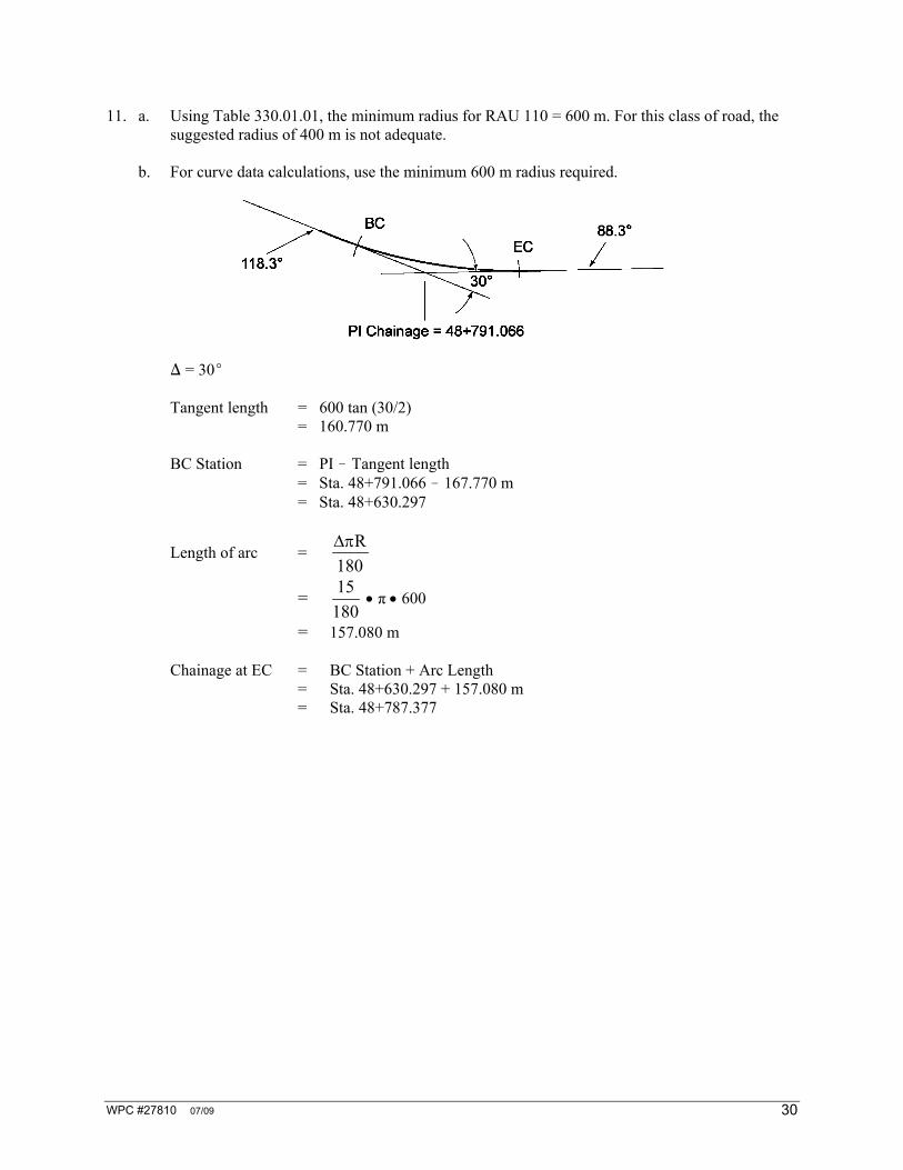
11. a. Using Table 330.01.01, the minimum radius for RAU 110 = 600 m. For this class of road, the suggested radius of 400 m is not adequate.
b. For curve data calculations, use the minimum 600 m radius required.
) = 30E
Tangent length = 600 tan (30/2) = 160.770 m
BC Station = PI ! Tangent length
= Sta. 48+791.066 ! 167.770 m = Sta. 48+630.297
Length of arc = R
180
= 15
180 π 600
= 157.080 m
Chainage at EC = BC Station + Arc Length = Sta. 48+630.297 + 157.080 m = Sta. 48+787.377

WPC #27810 07/09 31
c.
The road is a four-lane highway. Therefore, passing sight distance is not critical — stopping sight distance is the ruling factor. Using Tables 1.2.5.3. and 2.1.2.10 to determine that a range of minimum stopping sight distance of 180 – 250 meters are required for a design speed of 110 km/h. If you use the minimum and maximum radius values and refer to the nomographs in Figures 2.1.2.11 and 2.1.2.12, the clearance required ranges from 12.6 to 13.2 m approximately.
12.
Given: 4 lane RAD 100 Δ = 23°41'20" = 23.6944° T = 72.00 m a. The existing radius: T = R tan Δ/2 Therefore R = (tan Δ/2)/T Therefore R = 343.231 m
b. Length of arc = R
180
= 23.6944 343.231
180
= 141.942 m Therefore EC chainage = Sta. 5+046.000 + 141.942 m = Sta. 5+187.942

WPC #27810 07/09 32
c. Using Table 330.01.01, the minimum radius for an RAD 100 class road is 440 m. Therefore, the existing radius is not up to standard for the proposed upgraded classification. The road should be posted at 95 km/h (90 km/h = 340 m minimum radius; 100 km/h = 440 m minimum radius) or the next lower practical value.
d.
Using Figure 340.A, stopping sight distance C clearance ranges from 11.30 to 13.0 m. Trees should be cleared to a distance of (C + 1 1/2 lanes). If we use 11.30 m as an example, we have:
= 11.3 + (1 1/2 × 3.75) = 16.925 m
Therefore, trees will have to be cleared an extra 7.925 m.

WPC #27810 07/09 33
SELF-TEST ANSWERS
(Module 9 – Vertical Alignment)
1. Review Section 9.1.
2. K = L
A where K = Rate of change in metres/one percent change of grade
L = Horizontal length of the vehicle curve in metres A = Algebraic difference of the two tangent grades Review Section 9.2. 3. Review Section 9.3. 4. Review Section 9.2. 5. Ensure that positive drainage is provided and surface water does not pond creating a safety hazard.
This is of importance where the road is kerbed.

WPC #27810 07/09 34
SELF-TEST ANSWERS
(Module 10 – Intersections)
1. Review Section 10.1.1. 2. Diverging, merging, crossing and weaving. Review Figure 10.1.2. 3. Major conflict areas are where head-on, right angle, or rear end collisions may occur. Minor conflict
areas are where side swipe collisions may take place. 4. Sight distance. Review Section 10.1.3. 5. Vehicle paths. Review Section 10.1.3.