survey technique and engineeringespeaktechnology.com/wp-content/uploads/2016/12/survey...mr. survesh...
TRANSCRIPT

Mr. Survesh Saini – +91 99742 81750 [email protected]; [email protected]
SURVEY TECHNIQUE AND ENGINEERING
S M Takalkar1 Survesh Saini2
1. Managing Director, Takalkar Power Engineers & Consultants Pvt. Ltd. 2. Design Engineer, Electrical Department, Takalkar Power Engineers &
Consultants Pvt. Ltd. [email protected] [email protected]
Address Takalkar Power Engineers & Consultants Pvt. Ltd., Wing-B-424-430, Monalisa Commercial Complex,
Manjalpur, Vadodara, Gujarat-390011, India
Mr. Survesh Saini – +91 99742 81750 [email protected]; [email protected]
1.0 Introduction 1.1 Construction of EHV Transmission line is a very specific and specialized job. It involves lot of
precision and accuracy. The transmission line is standing for many years in the open terrain and faces vagaries of nature. The construction practice should therefore ensure that the parameters, on which the design of transmission line is made, are not exceeded.
1.2 The construction mainly includes the following activities. Survey & Alignment Foundation Work Erection of Super Structure Stringing of Shield wire & Conductor Testing & Commissioning
1.3 Each of above activity can be further divided into sub-activities. All the erection activities are based on the design inputs as well as site situation. For example, the type of tower and foundation to be adopted will depend upon the profile & site situation, where as the span/deviation angle limitations will be based on the design factors of the tower. This part deals with the general specifications for construction of EHV lines.
2.0 Survey & Alignment 2.1 Whenever EHV transmission line is to be constructed between two subs-stations, the ideal route
length will be the direct topographical distance between the two stations. However, this will not be possible as number of obstructions in the form of villages, town important civil establishments, big ponds, rivers etc. will prevent the straight run of the line. The obstruction will result into line deviations. It will therefore be necessary to carry out survey by various means. The survey will establish the following: • The topography of the route of the line. • The important deviation points of the line. • The approximate quantity of Towers and extension. • First hand information regarding the soil strata along the route, leading to approximate
estimation of foundation work quantities. • The obstructions which may result into line deviations. • Major River, Railway, Road and Power line crossings and type of structures for the same. • Information regarding availability of inputs for foundation work (cement, aggregates, steel
and water). • Right of way problems which are likely along the route. • Cost of transportation of material to various locations. • Tentative time frame for completing the work.
2.2 It is also usual to make trial pits or carry out soil investigation along the proposed route of the transmission line at certain fixed interval or at the points where abrupt change in soil strata is suspected. This exercise results in to the approximate estimation of the foundation types and excavation/concrete volumes and the re-enforcement for the foundation work. The various stages of survey works are described in details as under.
2.3 Reconnaissance and Route Alignment Survey 2.3.1 A provisional route of transmission line is initially plotted on survey maps (topo sheets) and
a reconnaissance/ walkover survey is carried out. This is essential to fix up angle tower

Mr. Survesh Saini – +91 99742 81750 [email protected]; [email protected]
positions tentatively, since many of the physical features on the ground may not be clearly available in the survey map due to developments that might have taken place subsequent to the preparation of the maps by department of survey of India. The topo sheets are obtained from the office of The Survey of India, Dehradun by indicating the Longitude & the Latitude of the proposed route of the transmission line. In most of the cases more than one Topo sheets are required to cover the route of the line.
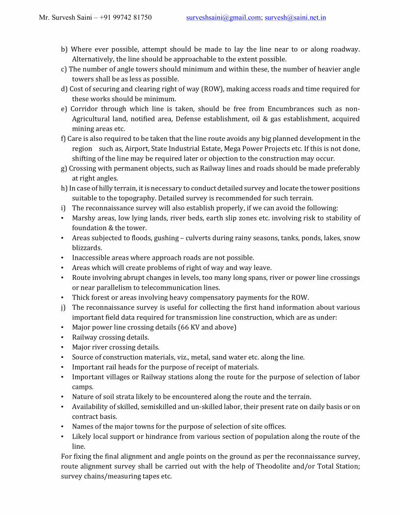
ROUTE MAP
2.3.2 The reconnaissance survey helps in collecting the first hand information regarding various important field data required for transmission line works. The reconnaissance survey is carried out by using GPS (Geographical Positioning System). The general points to be kept in view while establishing the preliminary route at the time of reconnaissance survey are as under. a) The route should be as short and as straight as possible.
22°1
5'
EXISTIN
G 400 KV TOWER L
INE
DAM
DAM
198, VISHWAMITRI TOW N SHI P, OPP. GUJAR AT TRACTOR S, VAD ODAR A-390 011
SUR VEYED & PREPARED BY-
POWER CONSULTANTS & AGENCIES, VADODARA
BY CHKD APPD PR OJ. ENGR
DRAWING NO. R EV.
R EVISIONS
0E
DATE
PCA/AC/KBPL/400kV/RECCAY/RM-01
RECONNAISSANCE SURVEY OF 400 kV D/C
1 : 50000
SCALE
Project:
T itl e:
NO
w ww. powercons ultant .inf o
EXISTING 400 KV D/C
LINE
Dhadhipara
Bat ra
Lahrapara
Nagrahi
T-05
T-05
T-05
T-05
T-05
Cart
Trac
k
ROADL 053
22°2
0'22
°25'
22°2
5'22
°20'
22°1
5'
82°30'82°25'82°20'82°15'82°10'
82° 30'82°25'82°20'82°15'82°10'
Borewells
20 0
200
PO
PS
R.F. / PF
Tree
Pol ice stat ion
Reserved/Protected forest
Post office
Bench-mark
Heights point
Heights triangulated
Hutment
Wells lined, unlined
Forest
Pond
Temple, Mosque
Devel opment
R oads met alled/Asphalted road
Roads un metalled
Rail ways broad gauge
200Contours with heights
Power/Te lephone line
Rail ways other gauge
Towns or Villages
RiverProposed route with AP
Industries
LEGEND :-
Cart-track
Canal
Stream
Scrub
Boundary state
Boundary tahsil
Boundary district
TAM
ILNA
DU
KE
RA
LA
HIMACHAL
CHH
ATI
SG
ARH
MADHYA PRADESH
KAR
NAT
AKA
PRADESH
ANDHRA
MAHARASHTRA OR ISSA
UTTARAN CHAL
UTTARRAJASTHAN PR ADESH
PUNJ AB
HARY
ANA
PRADESH
ASSAMPRADESH
B HUT AN
MEGHA LA YA
BA NGLA DES H
JHARKHAND
BENGALWEST
BIHAR
MIZ ORA M
MA NIP UR
NAGA LA ND
ARUNACHAL
KASHMIRJ AMMU &
GU JARAT
Coal Bearing Area
Coal Zone Al otment Area
82°35'
82° 35'
CHAPI WATER SCHEME
EAST OFKARTALI
AREA BETWEENKARTALI & DIPKA
NUNBERA
RATIJA
DIPKA
GEVRA
PONRI
NARAIBODH
KARTALIBLOCK
SARAIPALIBLOCK
DUMARKACHHARBLOCK
BANKI
BAGDEWA DILWADIH
SINGHALIBLOCK
BLOCKBLOCK
BLOCK
PROPOSED COALEXTENSION AREA
COALEXTENSIONAREA
PROPOSED
BHILAI
N O N C O A L Z O N E A R E A
COAL BEAR ING AREA
COAL BEARING AR EA
C OAL BEAR ING AREA
COAL BEARING AREA
COAL BEARING AREA
COA
L BEAR
ING A
REA
DESCRIPTION ROUTE Length(Km.)
Sr.No.
2/0
3/06/0
4/0
7/08/0
9/0
10/0
17/0
18/0
20/021/0
22/ 0
24/0
25/0
26/0
27/0
30/0
29/0
28/0
31/0
32/0
34/0
35/0
36/0
37/0
38/0
39/040/0
41/0
42/0
43/044/0
45/046/0
1/011/0
12/0
15/0
5/0
13/014/0
16/0
19/0
23/0
33/0
GANTRY
18/118/218/318/418/518/622/1
22/222/3
22/4
30/3 30/1
30/2
19/119/2
20/1
20/2
20/3
20/4
21/121/221/321/421/5
23/123/223/3
23/423/5
24/124/2
24/3
25/1
25/2
25/3
27/1
27/2
28/128/228/3
28/429/129/229/329/430/4
30/5
30/6
33/1
33/2
33/3
34/1
34/2
34/ 3
34/4
34/5
34/6
34/7
34/8
35/1
36/1
36/2
37/1
37/2
37/3
38/138/2
38/339/139/239/339/4
40/140/ 2
40/340/4
40/540/6
40/ 740/8
40/940/10
40/11
41/141/241/342/142/2
43/143/2
43/344/144/2
45/145/2
17/1
16/114/1
11/1
10/110/2
10/3
9/1
9/2
8/18/2 7/17/2
6A/0
4A/0
2/12/2
2/3
Mr. Survesh Saini – +91 99742 81750 [email protected]; [email protected]
b) Where ever possible, attempt should be made to lay the line near to or along roadway. Alternatively, the line should be approachable to the extent possible.
c) The number of angle towers should minimum and within these, the number of heavier angle towers shall be as less as possible.
d) Cost of securing and clearing right of way (ROW), making access roads and time required for these works should be minimum.
e) Corridor through which line is taken, should be free from Encumbrances such as non-Agricultural land, notified area, Defense establishment, oil & gas establishment, acquired mining areas etc.
f) Care is also required to be taken that the line route avoids any big planned development in the region such as, Airport, State Industrial Estate, Mega Power Projects etc. If this is not done, shifting of the line may be required later or objection to the construction may occur.
g) Crossing with permanent objects, such as Railway lines and roads should be made preferably at right angles.
h) In case of hilly terrain, it is necessary to conduct detailed survey and locate the tower positions suitable to the topography. Detailed survey is recommended for such terrain.
i) The reconnaissance survey will also establish properly, if we can avoid the following: • Marshy areas, low lying lands, river beds, earth slip zones etc. involving risk to stability of
foundation & the tower. • Areas subjected to floods, gushing – culverts during rainy seasons, tanks, ponds, lakes, snow
blizzards. • Inaccessible areas where approach roads are not possible. • Areas which will create problems of right of way and way leave. • Route involving abrupt changes in levels, too many long spans, river or power line crossings
or near parallelism to telecommunication lines. • Thick forest or areas involving heavy compensatory payments for the ROW. j) The reconnaissance survey is useful for collecting the first hand information about various
important field data required for transmission line construction, which are as under: • Major power line crossing details (66 KV and above) • Railway crossing details. • Major river crossing details. • Source of construction materials, viz., metal, sand water etc. along the line. • Important rail heads for the purpose of receipt of materials. • Important villages or Railway stations along the route for the purpose of selection of labor
camps. • Nature of soil strata likely to be encountered along the route and the terrain. • Availability of skilled, semiskilled and un-skilled labor, their present rate on daily basis or on
contract basis. • Names of the major towns for the purpose of selection of site offices. • Likely local support or hindrance from various section of population along the route of the
line. For fixing the final alignment and angle points on the ground as per the reconnaissance survey,
route alignment survey shall be carried out with the help of Theodolite and/or Total Station; survey chains/measuring tapes etc.

Mr. Survesh Saini – +91 99742 81750 [email protected]; [email protected]
2.4 Detailed Survey 2.4.1 The main objective of carrying out detailed survey is to prepare longitudinal and cross section
profiles on the approved route alignment and to prepare the route plan showing details of deviation angles, important objects coming within the right of way and show the landmark points/objects along the route with their distance from the alignment of line. Work of detailed survey is normally done in two stages: 1. By actual field observation taking level readings and calculating distances, level differences,
deflection angles, offset distances etc. 2. By plotting of profiles on graphed tracing papers of mm x mm size.
2.4.2 The use of Total Station facilitates quick measurement of distance, ground levels and the angles between the two reference points. The Total Station is located at fixed point and there after the prism mounted in a stand is moved along the route of the line, preferably at an interval of 20 meters. Each reading gives the distance and level difference. These readings are stored in the memory of Total Station (TS). The data is there after transferred to the computer.
2.4.3 Field Observation Recording and Calculations 2.4.3.1 The method of taking level readings for preparation of longitudinal and cross section profile can
be one of the following • By chain and dumpy level • By tachometric survey with Theodolite • By using Total Station and the prism
First method is more useful in plain areas where chaining can be done easily with the help of semiskilled surveyors. Tachometric method offers a great advantage in hilly regions and such other inaccessible places where chaining is not possible. This method needs skilled surveyors having good understanding of the use of Theodolite and basic knowledge of trigonometry. In this method, both traversing and leveling is done by means of a tachometric Theodolite. The horizontal and vertical distances are computed with the help of readings of the stadia wires taken on the staff held at the reading point. The accuracy of the work will depend upon the quality and cost of the equipment.
The range of operation of Theodolite is much higher than the dumpy level. The surveyor and his team will move on an approved route and take ground levels in the field book at an interval of 20 meters.
2.4.3.2 As stated in 2.4.2 above, the Total Station is the most modern equipment for surveying. It saves lot of time and the observations are highly accurate. This equipment is very expensive and needs lot of precautions in handling. If the length of line is very short, Theodolite can also serve the purpose.
2.5 Plotting of Profiles 2.5.1 From the field book entries route plan and longitudinal profile, commonly referred to as “route
profile” or “survey chart” is prepared in the drawing office. These charts are prepared and plotted on 1mm/5mm/1cm square paper of formed drawing sheets of graphed tracing paper. The scale normally preferred is 1:200mm-vertical; 1:2000mm-horizontal.
2.5.2 The profile shall include the following: • The longitudinal profiles along the centre-line of the transmission line route including the
bottom conductor catenaries.

Mr. Survesh Saini – +91 99742 81750 [email protected]; [email protected]
• The cross-section profile wherever appreciable difference in level exists, with references to centre-line level. In such cases the cross-section levels shall be taken at each 50/100m intervals.
• Route plan giving details of all objects lying within the right of way and just along the boundary of right of way.
• Angle of line deviation duly marked left (L) or right (R) as the case may be. • Objects and their distances along the route within the right of way from centre line, nearby
villages, important pucca roads & or rivers/canals, cart tracks etc. should be marked on the route profile.
• Crossing details with any other power or telecommunication lines, roads, railway lines, canals or rivers should be marked as clearly as possible.
• Readings should be taken and charts should show, levels of roads, canal embankments, maximum water/flood levels, railway rail top levels, heights of supports/lines being crossed, all trees coming within the clearance zone.
• It is advisable to prepare an independent route profile for Major River crossing section deploying tall special towers or normal towers on piles in the river crossing section, as the river crossing is a special task in the construction process which involves special design.
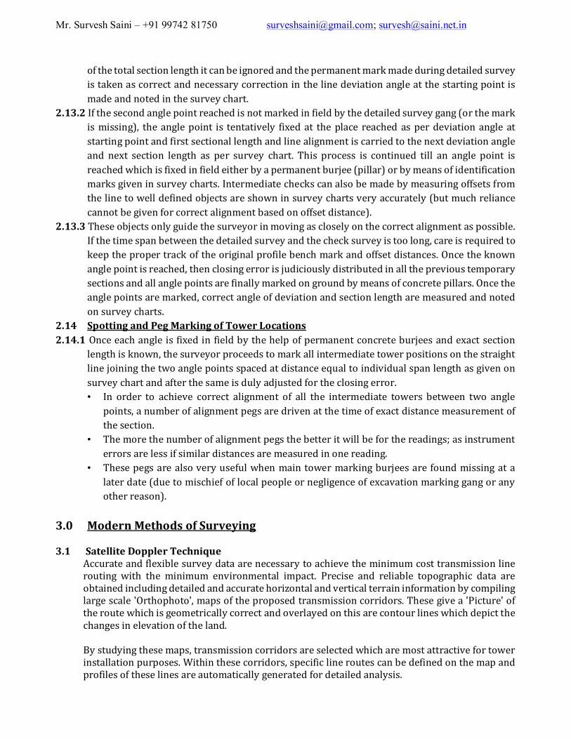
2.6 Tower Spotting 2.6.1 The work of tower spotting is a very precise job as it has an implication on overall cost. After the tower designs are finalized, the tower spotting chart or structure limitation charts are
prepared. Similarly the drawing of the sag template and its replica is prepared on Acrylic sheet. Application of Sag Template helps to decide optimum tower position on Survey Chart., which ultimately helps in finalizing the quantity of each type of tower and their extensions (3 meter & 6 meter etc).
2.7 Preparation of Sag Template 2.7.1 Sag template is a very important tool for the surveyor by the help of which Tower spotting can
be done. Depending upon the maximum specified permissible temperature of the conductor and zero wind condition the ground clearance is to be maintained by the line. Similarly under the specified minimum temperature of the conductor surface, with zero wind condition, the tower tensions should be within the specified limits. The sag template curves are first prepared on tracing paper and the blue print is taken out from the tracing. Their replicas on Acrylic sheets are prepared with the itching process. The Acrylic sheets are normally 2.5 to 3 mm thick.
2.7.2 The sag templates have the following curves itched on them. • ‘Cold or Uplift Curve’-Showing sag of conductor at specified minimum temperature and zero
wind. • ‘Hot’ or ‘Maximum Sag Curve’ showing maximum sag of conductor under zero wind and
maximum temperature and sag tolerances are also allowed to take care of stringing error, conductor creep or snow incidences.
• Ground clearance Curve-drawn parallel to hot curve and at a distance equal to specified minimum ground clearance.
• Tower footing Curve-For normal tower drawn parallel to hot curve under ground clearance curve and separated by a distance equal to maximum sag at design span.

Mr. Survesh Saini – +91 99742 81750 [email protected]; [email protected]
2.7.3 In erecting an overhead line all the spans cannot be kept equal to normal design span because of the profile of the ground and proper ground and object clearance considerations. A constant tension is calculated which will be uniform throughout the Section (from one tension tower to other tension tower), however the sags in individual spans will vary according to their respective spans. The ‘Cold and Hot’ Template Curves are plotted as parabola, to the same scale as the survey chart for the minimum and maximum sags for the normal span (specified in the tender specifications).
2.8 Application of Sag Template for Tower Spotting 2.8.1 The Sag Template is an important tool for correct spotting of the towers after the detailed survey
work is completed. The following are the steps to be followed for correct application of sag template. • The acrylic sag template is applied to the ground profile by moving the same horizontally
while always ensuring that the vertical axis is held vertical with reference to graphed lines of the tracing paper below.
• The structure positions are marked where the tower footing curve just touches the profile, while the ground clearance curve is just clear and above the profile to the left or right of the centre line up to a distance equal to maximum cross area spread on either side.
• Besides normal ground clearance, the clearances between power conductor and objects like, other power or telecommunication lines, houses, trolley wires, roads, railway tracks, canal embankments etc., shall be checked.
• Extra clearance can be obtained either by reducing the span or providing extension to tower body, depending on which alternative is most economical.
• The weight span on either side of a tower can be easily obtained by marking the low points of sags (Null Point) in two adjacent spans and then reading the distance between the two.
• On inclined spans, null point may be outside the span. • This indicates that the total weight of conductor is taken up by the higher tower and the lower
tower is being pulled up by a force equal to the weight of conductor between lower support and the null point.

Mr. Survesh Saini – +91 99742 81750 [email protected]; [email protected]
• Should the upward pull of the uphill span becomes greater than downward load of the next adjacent span, actual uplift will be caused and the conductor would tend to wing clear of the tower upwards.
• For any easy check of whether a tower is under uplift or not, the following method may be adopted.
• The Template is applied horizontally until the tops of alternate supports coincide with the Cold Curve.
• If the support is under uplift and has to be extended so as to be above it and in case requisite standard body extension do not suffice for doing this, tower which is designed to take uplift will have to be used.
• However, for the stability of the line, it is not desirable to place a tower in such a position where it is always under permanent uplift condition.
• In case it becomes mandatory due to route compulsion, the cross-arms of the tower subjected to up lift shall be designed to take the extra upward pull.
• The intermediate spans shall be as near as possible to the normal design span. • In case an individual span becomes too short on account of undulations in ground profiles,
one or more line supports of the Section may be extended by inserting standard body extensions.
• Even if the line does not deviate for a long run, sections have to be provided after every 12 to 15 tangent towers. (i.e. 3 to 4 km. length).
• For this purpose a small angle tension tower designed for 15° should only be used. • This is mandatory to afford better stability of the line against Transverse wind forces and to
facilitate easy stringing. • Besides 15° angle tension tower is most economical amongst the standard angle tension
towers. 2.9 Use of computer for preparing sag template and the tower spotting 2.9.1 Before taking up the tower design on hand, Sag and Tension charts are required to be prepared.
These charts indicate the values of sag and tension of conductor and the earth wire at Maximum temperature, minimum temperature and every-day temperature under 100%,36%(66%) and 0% wind pressure. Normally, in plain terrain in India the maximum, minimum and every-day temperatures are considered as 0 Deg.C 75 Deg. C and 32Deg. C. These values may change in the region experiencing snow or Sub-Zero temperatures. If the conductor is required to carry large block of power, the maximum surface temperature of conductor can be taken up to 95Deg. C. For Earth wires the maximum temperature is taken as 53Deg. C
2.9.2 Based on the sag tension charts, the sag template curves can be plotted on the computer through a specific programme. The full scale print out of the curves is then used to prepare the Acrylic Sag Template by itching process.
2.10 Towers Spotting Data 2.10.1 Since each tower is designed to withstand a definite load only, in each of transverse, vertical and
longitudinal directions, the surveyor must know these limitations for the various types of towers available for use on line so than he can spot an appropriate type of tower structures along the route. These limits are given in a chart form called ‘Structure Limitation Chart or “Tower Spotting Data” which is prepared by the design department of the utility /contractor. These charts define the limits for permissible ruling span, weight span, wind span, individual span and the degree of

Mr. Survesh Saini – +91 99742 81750 [email protected]; [email protected]
the deviation allowed on each of the standard towers. These charts are made for normal towers only.
For all special crossings individual tower checking is essential by the design department. These
charts also indicate the additional angle of deviation which can be allowed in the tower by limiting the spans, so that the design load limits of the tower are not exceeded.
TOWER SPOTTING
V:-1 : 200
H:-1 : 2000
SCALE DRAWING NO. REV. 0A Title: CLIENT - Project:
TOWER SPOTTIN G & SAG CUR VE OF 400kV D/C TR AN SMISSION
LINE
DATUM 262.0m
AP48 - CH:5361 2.02m
AP49 - CH:5486 7.67m
PRO PO SED SU B ST ATION
AP-45(14°48'23 ")R AP-46(75°43'41 ")L
422
411.66 422
A / 198 VISHVAM I TR Y TOWNSHIP, OPP. GUJ AR AT TRAC TOR S, VADODARA - 390 011 Ph.(0265) 2343001 Fax.(0265) 2356291 E-mail: sm takalkar@po wercon sultant.info ,[email protected]: www.powercon sultan t.info POWER CONSU LTANTS & AGENCIES
CONSULTANT: -
C UM ULATIVE LEVEL S(M ) R EDUC ED
DETAILS & INT ERFER ENCE C R OSSING
C HAINAGES(M )
+3M +6M +9M
Ground C learance at 13.26 M tr.
C onductor s tringing point at 22.21 Mtr.
+3M
+6M
+9M
Ground C learance at 13.26 M tr.
C onductor s tringing
point at 22.21 M tr.
+3M +6M +9M
Ground Clearance at 13.26 M tr.
C onductor s tringing point at 22.21 M tr.
+3M +6M +9M
Ground C learance at 13.26 M tr.
C onductor s tringing
point at 22.21 Mtr.
Hot C urve 85° C
Ground C learance C urve
Hot C urve 85° C
Ground Clearance C urve
Hot C urve 85° C
Ground C learance C urve
Cold C urve 0° C Cold C urve 0° C
C old C urve 0° C
Wind Span T
L R
Weight Span (Cold)
L RT
Weight Span (Hot) L R
T
Loc . No
205.83211
416.83 427.16 206.46220.7
431.1
207.26223.84 DA+645/1 157
Wind Span
T L R Weight Span (Cold)
L R T
Weight Span (Hot) L R
T Loc. No-
211205.83 416.83
419.48214.28 205.2 423.41
219.01 204.4 DA+345/2 158
Wind Span
T
L R Weight Span (Cold)
L R T
Weight Span (Hot) L R
T
Loc . No-
000.00211211
207.72
000.00207.72 202.99
000.00202.99 DD+0
46/0159
Wind Span T
L R Weight Span (Cold)
L R T
Weight Span (Hot)
L R T
Loc . No-
211211422
413.36201.3212.06 411.82
198.16213.66 DB+3 45/0 156

Mr. Survesh Saini – +91 99742 81750 [email protected]; [email protected]
2.11 Preparation of Tower Schedule 2.11.1 In order to decide the tower type for a particular location, following information is required from
the design department: • Angle of line deviation on tower • Whether it is to be used as section tower or dead end tower • Sum of adjacent spans • Weight span on tower • Whether an immediate lower size of tower can be used in place of the actual angle tower by
limiting the span. • Whether a river can be crossed using normal tower with/without extensions or by providing
special tower or by locating towers in mid stream by providing the pile foundations. • Whether a hill side extension will be required.
2.12 Check Survey 2.12.1 Check survey is carried out for the following.
• To reconfirm the work carried out during detailed survey. • To locate and peg mark the tower position on ground, corresponding to the route profiles. • To give direction pegs.
2.13 Checking and Line Alignment 2.13.1 In this operation, traversing is done from the known fixed angle point (the starting point or any
other obligatory point fixed by the purchaser) in the direction of given line deviation and up to a distance equal to the section length between the starting point and the next angle point. If next angle point is firmly marked in field by means of a permanent peg mark (concrete burjee) then the closing error is noted both in longitudinal and transverse directions. If the error is within 1%
Sr. no.Tower
NoType of Tower
Angle of deviation
(° ' ")
Span(m)
Sum of Adj. Span
(m)
Section Length
(m)
Wind span(m)
Weight span(m)
Remarks
0 Gantry Gantry 0° 70.51 65.1308141.02
1 1/0 DD+0 50° 17' 0" LT 407.7 141.02 203.85 209.1252266.68 33kV, 11kV LINE & ASPHALT ROAD
2 2/0 DB+0 5° 55' 37" LT 626.68 266.68 313.34 322.6374360
3 2/1 DA+0 720 360 374.8866360 2 No. NALA
4 2/2 DA+0 610 305 259.828250
5 2/3 DA+0 534.55 267.275 291.26284.55 11kV POWER LINE
6 3/0 DC+0 23° 42' 9" LT 670.73 1254.55 335.365 318.9964
386.18 CART TRACK7 4/0 DD+3 51° 0' 26" RT 543.94 386.18 271.97 40.8558
157.76 NALA8 4A/0 DB+27 SEC TOWER 379.57 157.76 189.785 424.4552
221.812 No. 400kV POWER LINES, ASPHALT
ROAD & NALA
Tower Schedule
Mr. Survesh Saini – +91 99742 81750 [email protected]; [email protected]
of the total section length it can be ignored and the permanent mark made during detailed survey is taken as correct and necessary correction in the line deviation angle at the starting point is made and noted in the survey chart.
2.13.2 If the second angle point reached is not marked in field by the detailed survey gang (or the mark is missing), the angle point is tentatively fixed at the place reached as per deviation angle at starting point and first sectional length and line alignment is carried to the next deviation angle and next section length as per survey chart. This process is continued till an angle point is reached which is fixed in field either by a permanent burjee (pillar) or by means of identification marks given in survey charts. Intermediate checks can also be made by measuring offsets from the line to well defined objects are shown in survey charts very accurately (but much reliance cannot be given for correct alignment based on offset distance).
2.13.3 These objects only guide the surveyor in moving as closely on the correct alignment as possible. If the time span between the detailed survey and the check survey is too long, care is required to keep the proper track of the original profile bench mark and offset distances. Once the known angle point is reached, then closing error is judiciously distributed in all the previous temporary sections and all angle points are finally marked on ground by means of concrete pillars. Once the angle points are marked, correct angle of deviation and section length are measured and noted on survey charts.
2.14 Spotting and Peg Marking of Tower Locations 2.14.1 Once each angle is fixed in field by the help of permanent concrete burjees and exact section
length is known, the surveyor proceeds to mark all intermediate tower positions on the straight line joining the two angle points spaced at distance equal to individual span length as given on survey chart and after the same is duly adjusted for the closing error. • In order to achieve correct alignment of all the intermediate towers between two angle
points, a number of alignment pegs are driven at the time of exact distance measurement of the section.
• The more the number of alignment pegs the better it will be for the readings; as instrument errors are less if similar distances are measured in one reading.
• These pegs are also very useful when main tower marking burjees are found missing at a later date (due to mischief of local people or negligence of excavation marking gang or any other reason).
3.0 Modern Methods of Surveying 3.1 Satellite Doppler Technique
Accurate and flexible survey data are necessary to achieve the minimum cost transmission line routing with the minimum environmental impact. Precise and reliable topographic data are obtained including detailed and accurate horizontal and vertical terrain information by compiling large scale 'Orthophoto', maps of the proposed transmission corridors. These give a 'Picture' of the route which is geometrically correct and overlayed on this are contour lines which depict the changes in elevation of the land.
By studying these maps, transmission corridors are selected which are most attractive for tower installation purposes. Within these corridors, specific line routes can be defined on the map and profiles of these lines are automatically generated for detailed analysis.

Mr. Survesh Saini – +91 99742 81750 [email protected]; [email protected]
Before mapping is produced points with known coordinates are established throughout the area to control the photographs both horizontally and vertically.
Each of the various components of route survey under this technique are discussed in following paras.
3.1.1 Initial Survey
Under initial survey, one or more preliminary transmission corridors are established. These are established with the help of Topo sheets of the region and after having a walkover survey along the tentative route alignment.
3.1.2 Controls
Control points are fixed along the route for which the latitude, longitude and elevations are accurately known. An initial reconnaissance will establish the most suitable sites for the control points based on terrain conditions. Control points need not be proposed along the transmission line corridors, they can be at the sides of roads or elsewhere they cause the minimum impact on the land owners. Each of these points is to have a permanent marker placed on the ground. This is because the field staff is required to return to the same points again and again during the execution period of the project. Two types of permanent markers are used. For the preliminary control, a concrete cylinder is placed approximately 6 ft in the ground with the top of the cylinder flush with the surface. This is used for the 8 to 10 points which are surveyed using doppler satellite technique. Concrete markers are installed along the proposed route to provide the overall basis for the control net work. A receiver is placed on each control point to monitor the position of satellite. From this information, position coordinates are calculated for the receiver locations on the ground.
The remaining points are surveyed using the Inertial Survey system which coordinates the control points (in x, y and z) between any two of the previously established doppler points. For these points, a 4 ft long steel bar is driven in the ground so that the top is flush with the surface. Inertial Survey System is operated from a helicopter in order to produce large number of coordinated points in a minimum amount of time.
3.1.3 Orthophoto Mapping
Aerial survey mapping (Photogrammetry) has a definite application to the planning and design of transmission lines and is used in the advanced countries both in the preliminary stages of line routing and in the preparation of plan and profile maps for structure plotting.
Aerial photography is taken immediately after fixing the control points along the tentative route alignment in order to minimise the loss of targets due to whether or any other problems. Here it is necessary that these control points show up very clearly when the aerial photography is taken.
Orthophoto is a photograph of the area which is true to scale in all respects. It gives the transmission line engineer a oomplete picture of all ground features with the added bonus of the required vertical data. It is produced from aerial photography using computer technique. A band, approximately 2 kms wide is generally mapped along the preliminary corridors. The horizontal scale for the mapping is 1:10,000 with 1 m contour intervals in the plain section and 5 m contour in the mountaneous terrain. This gives a good basis for selection of tower site with spot height accuracy to within 1 to 2 metres.
Some of the specific advantages of using photogrammery techniques for transmission line survey are as under.

Mr. Survesh Saini – +91 99742 81750 [email protected]; [email protected]
3.1.4 Advantages Determines the best route : The broad coverage provided by aerial photographs facilitates selection of best line route. Potential routing difficulties can be recognised and avoided before any field activity begins. Also angles can be selected easily for efficient and economical use of structures.
3.1.5 Economical
Aerial surveying has definite economic advantages-both in respect of time and cost. Where mountaineous/rugged terrain, inaccessible swamp land or heavily populated areas are encountered, even greater economies can be realised.
3.1.6 Saves Times
Data that could take months to obtain by ground survey can be obtained by aerial survey in a much shorter period of time.
3.1.7 Greater Visual Details
The use of photogrammetry techniques provides visual details as well as permanent visual record of existing features which cannot be obtained by any other means.
3.1.8 More Accurate Engineering, Design & Construction Bids
Accurate plan and profile maps can be prepared from photographic enlargement, which help the designers to spot the towers and design the footings with greater accuracy and economy.
3.1.9 Flexibility
All necessary line data, including tower spotting, profiling etc. can be determined from the orthophotos for any number of route variation, without returning to the actual site. In fact, changes in the route alignment can be made with the minimum difficulty.
3.1.10 Confidential
Aerial surveys are confidential and therefore help in minimising the way leave problems. 3.1.11 Equipment required and their cost
Equipment required for Satellite Doppler Technique are : Equipment for control surveys i.e., Satellite doppler global position system, Inertial survey system and Electronic distance measurement system. Equipment for aerial phtography i.e. Aeroplane, Camera & Photomechanical laboratory.
Mapping equipment - Analytical stereo compilers. Cost of these equipments is definitely substantially high and as such initial investment for acquiring the same is much more. In regard to the operational cost, it may vary due to geographic location, distance from aerial survey station to job site, type of aircraft employed, quality of photography and degree of accuracy required.